

Page 1
Aquamantys® System
Generator Verification
Page 2

Table of Contents
Test Leads Required...................................................................................1
Aquamantys® Generator Adjustments .................................................................1
RF Activation .........................................................................................2
RF Leakage Current ...................................................................................4
Pump Head Rotation to Verify Flow Rate Accuracy .....................................................11
Load Pump Tubing Segment into Pump ...............................................................15
Intended Use of this Document
WARNING: The information contained in this document is intended for the use of qualied personnel only. Biomedical
technicians (e.g., ICC Certied Biomedical Equipment Technician [BMET]) or similar personnel performing the steps
outlined here shall be fully familiar with all documentation on the functions, operations, warnings and components
of the Aquamantys® System. Serious injury can result if the activities described in this document are attempted by
unqualied persons and if warnings identied in the text are neglected.
Note: The information contained in this document was accurate at the time of publication. Medtronic reserves the
right to make changes to the product described in this manual without notice and without incorporating those
changes into any products already sold.
No part of this document may be reproduced in any manner, or transmitted by any form or means electronic or
mechanical, for any purpose without the express written permission of Medtronic Advanced Energy.
Page 3
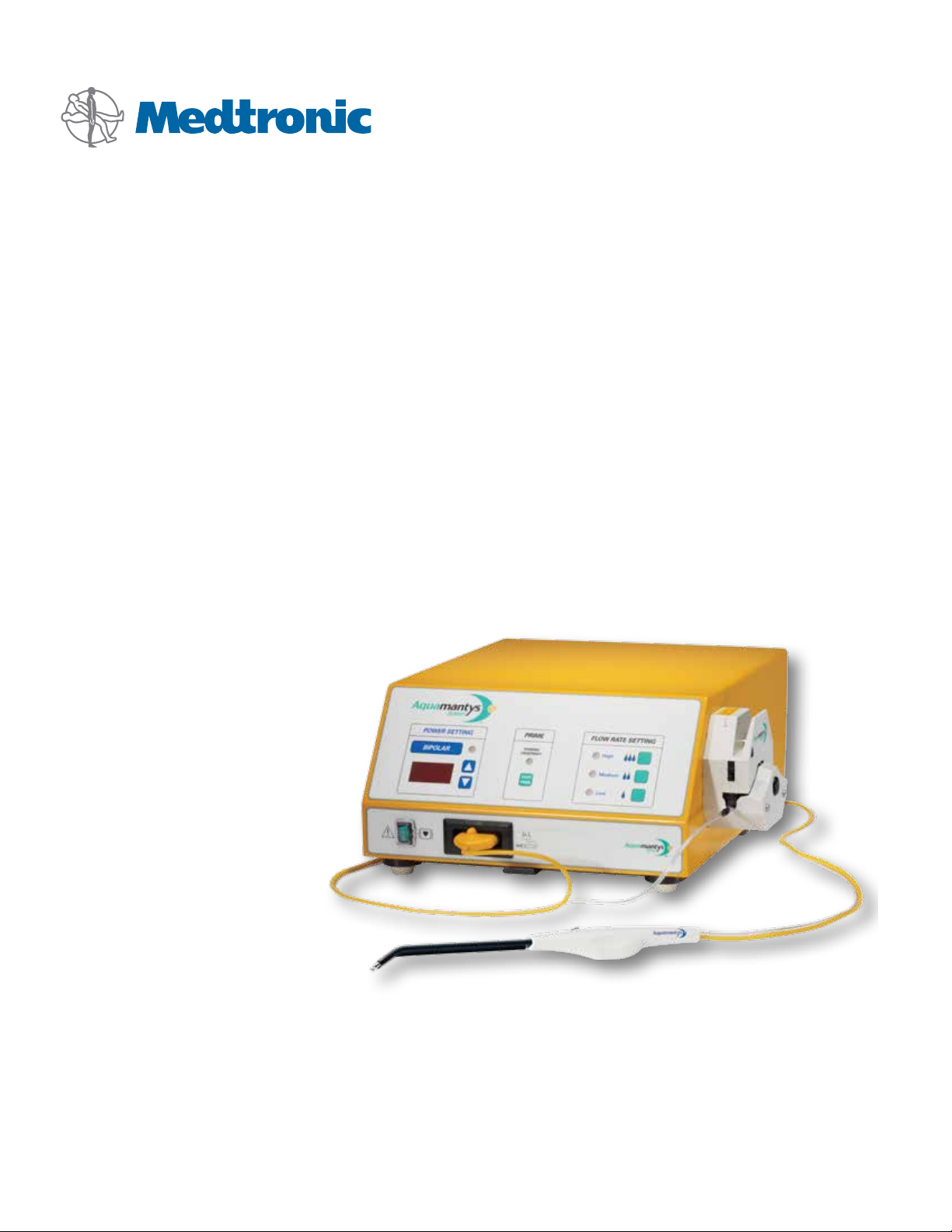
Test Leads Required
1
(1) Long red lead with (2) 4mm ends
2
(1) Long black lead with (2) 4mm ends
2
1
4
3
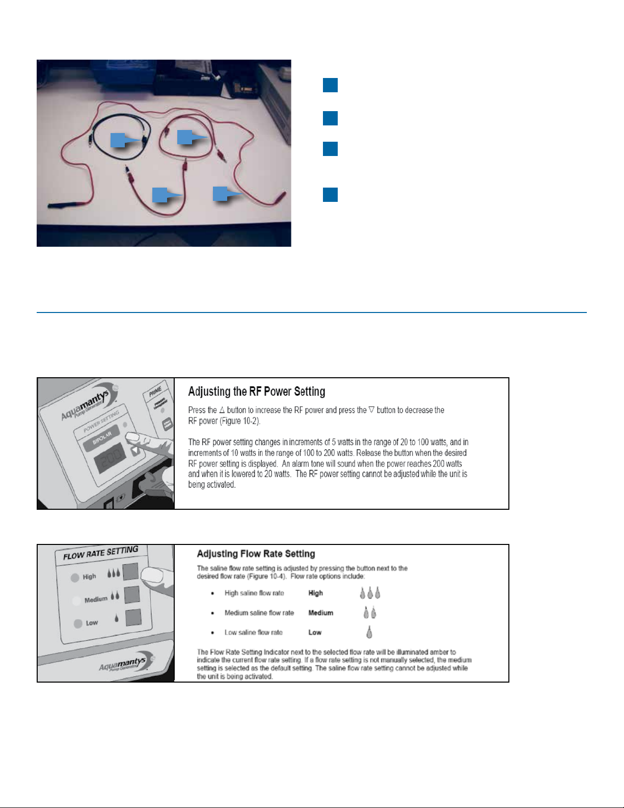
Aquamantys® Generator Adjustments
Power on Aquamantys generator, adjust power up and down
3
(1) Long lead with (1) 4mm end and (1) banana clip
4
(1) Short red lead with (1) 4mm end and (1)
2mm end
Adjust ow settings
1
Page 4
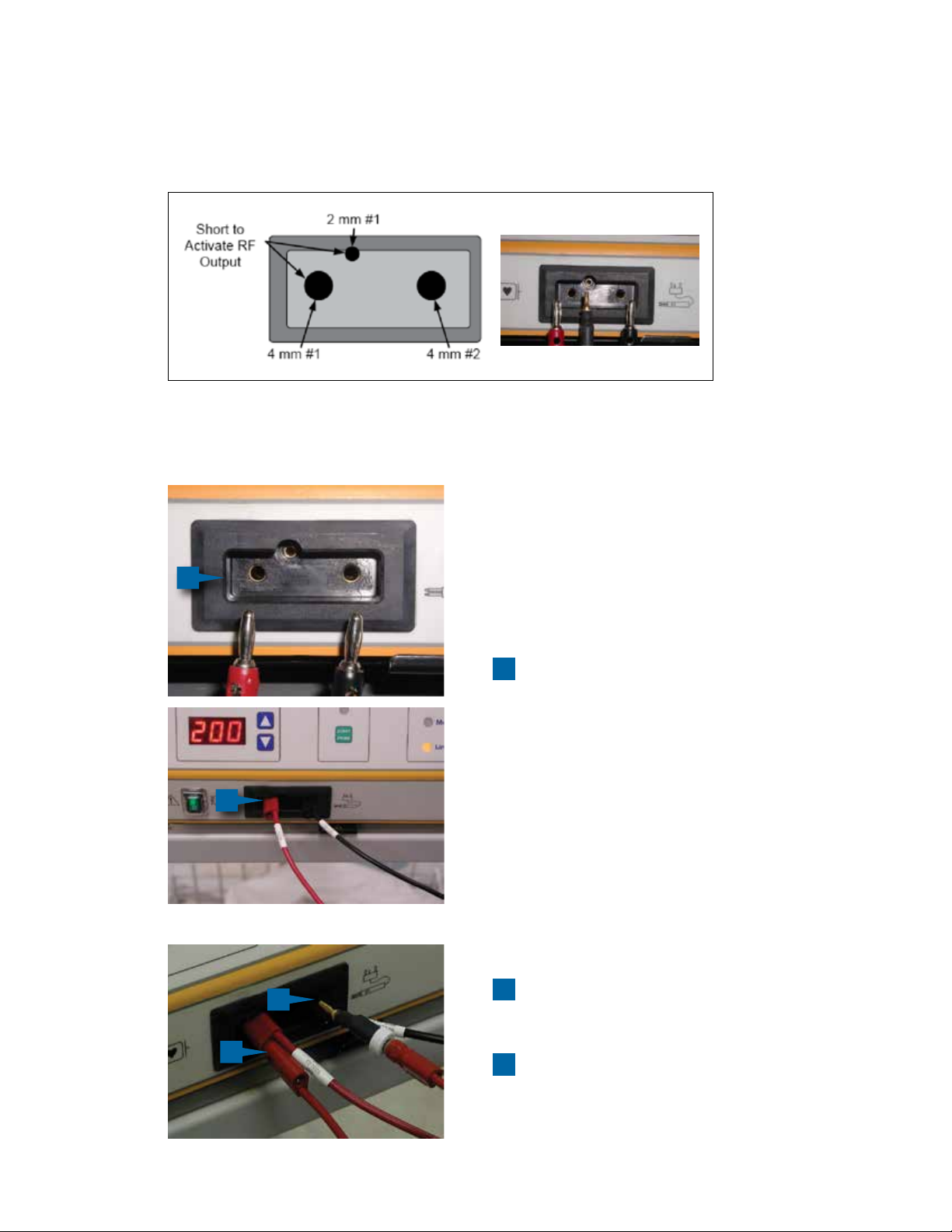
RF Activation
When 2mm connector #1 is shorted to 4mm connector #1, the Aquamantys® bipolar RF output will be active from
4mm connector #1 to 4mm connector #2
Figure 1 Aquamantys bipolar output socket; RF output activation
1
1
Insert red (active) and black 4mm test lead
ends into bipolar socket
1
2
2mm pin will activate RF when inserted into center
2
hole of bipolar socket
3
3
Insert short red 4mm end of test lead into long red
lead
2
Page 5
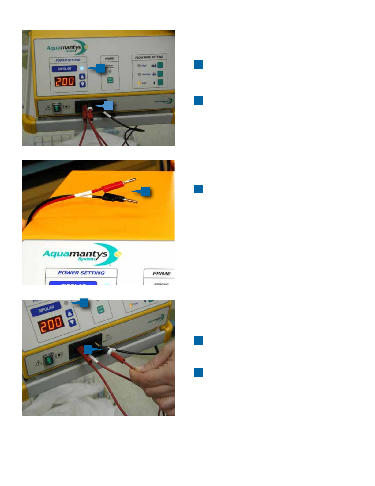
4
To activate RF output, insert 2mm pin of short red
5
lead into 2mm center hole of bipolar socket
5
Blue bipolar active LED will light up and stay lit
4
6
while RF is activated
6
WARNING: metal of loose ends of test cables
become extremely hot and will cause burn injury if
contact with skin is made while RF
is active
8
7
To deactivate RF output, remove 2mm pin from
7
bipolar socket
8
Bipolar active LED will go o
3
Page 6
RF Leakage Current
*
WARNING: Use extreme caution during this test. Metal ends of test leads are hot during RF activation and
will cause burning if in contact with skin!
1
1
2
1
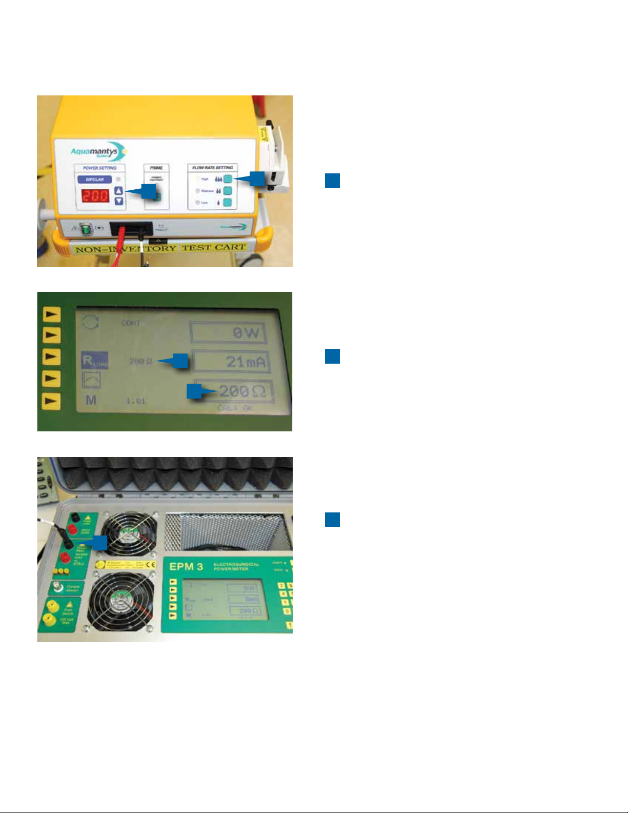
Power on Aquamantys® generator, adjust power to
200W, and ow rate to high
2
Power on electro-surgical safety analyzer (power
meter) and adjust resistance to 200Ω
2
3
Insert opposite end of black test lead into
3
inactive port of power meter
Do not attach red test lead from bipolar socket to
power meter at this time
*Electrosurgical power meter shown in this section is for illustrative purposes only. Customer test equipment may dier.
4
Page 7

4
4
Connect 3rd test lead with alligator clip end to the
earth ground stud on the back of the Aquamantys®
generator
5
5
Insert opposite end of 3rd test lead into active port
of power meter
6
Activate RF output
6
6
5
Page 8

7
Read current measurement on power
meter display
7
This reading must be below 100mA
8
Remove black test lead from inactive port of power
meter
8
9
Insert opposite end of red test lead connected to
9
active side of bipolar socket into the inactive port
of the power meter, read current measurement on
power meter display
10
10
This reading must be below 100mA
6
Page 9

RF Output Power:
12
11
11
11
Deactivate RF output and remove 3rd test lead from
power meter and Aquamantys® generator earth
ground stud
12
Set power of the Aquamantys generator
to 200W
13
Make sure RF output is not active at this point
13
7
Page 10

14
Insert red test lead into active port of power meter
and black test lead into inactive port
14
17
16
15
15
Adjust resistance on the power meter to 50Ω
16
Activate RF power and read measurement on
power meter display
Measurement should be 200W +/- 10%
17
Deactivate RF power after each measurement; power
can only be adjusted when RF is inactive
17
19
18
18
Repeat measurement with 100Ω resistance
19
Measurement should be 200W +/- 10%
8
Page 11

21
20
20
Repeat measurement with 150Ω resistance
21
Measurement should be lower than previous
readings at lower resistance (see power
curve below)
Output Power versus Resistance
22
22
Adjust power setting on the Aquamantys®
generator to 100W
9
Page 12

26
25
24
23
23
Take measurements at 50Ω
24
Measurement should be 100W +/- 10%
25
Take measurement at 100Ω
26
Measurement should be 100W +/- 10%
28
27
27
Take measurement at 150Ω
28
Measurement should be lower than previous
readings at lower resistance (refer back to
power curve above)
10
Page 13

Pump Head Rotation to Verify Flow Rate Accuracy
1
Close pump head by moving and locking the pump
1
2
head lever down toward the rear of the pump
generator
2
Remove grommet from pump head
3
Mark a visual reference point
3
4
Or use a piece of tape and stick to pump shaft
4
11
Page 14

5
Set the Aquamantys® generator power to 200W
5
6
6
Adjust ow rate to Low
7
Activate RF output
7
8
Using a stopwatch as a timer, count number
7
of complete revolutions of pump shaft in
15 seconds
Deactivate RF output between
measurements
Minimum revolutions = 17
8
Maximum revolutions = 23
9
9
0:15
00
12
Page 15

10
Count pump shaft revolutions in 15 seconds at
Medium ow rate
11
10
10
11
Minimum revolutions = 22
Maximum revolutions = 30
11
Count pump shaft revolutions in 15 seconds at
High ow rate
Minimum revolutions = 27
Maximum revolutions = 36
13
Page 16

12 12
12
Count pump shaft revolutions in 15 seconds at
Prime rate
Minimum revolutions = 31
Maximum revolutions = 42
Saline Flow Rate versus Power Setting
13
13
Replace grommet
14
Page 17

Load Pump Tubing Segment into Pump
1
3
1
Open pump head by moving pump head lever
toward front of the Aquamantys® generator
2
With black tubing insert facing toward front of
Aquamantys generator and white tubing insert facing
toward back of Aquamantys generator, insert tubing
segment into pump head
2
3
Black corner of pump head label points to direction of
black tubing barp, white corner of pump head label
points to direction of white tubing barp
4
Line tubing up inside of guide pins in front and back
and hold in place while closing pump head
4
15
Page 18

Caution: Federal Law (USA) restricts these devices to sale by or on the order of a physician.
For a listing of indications, contraindications, precautions, and warnings, please refer to the Instructions For Use (IFU) that accompany Aquamantys3 disposable devices and/or the
Aquamantys3 System User Guide.
For further information, please call 866-777-9400 or 603-742-1515.
You may also consult our website:
www.medtronic.com/advancedenergy
Medtronic Advanced Energy LLC
180 International Drive
Portsmouth, NH 03801
USA
www.medtronic.com/advancedenergy
Tel: (866) 777-9400
Fax: (866) 222-0900
International Telephone Numbers
Adriatic Regional Oce 385-1-488-1120
Australia 1800-668-670
Baltic Regional Oce 37-1-67560226
Belgium 32-2456-09-09
Canada 1800-217-1617
China 86-21-50800998
Czech Republic 420-2-9657-9580
France 33-470-679-800
Germany 49-2159-8149-209
Greece 30-210-67-79-099
Hong Kong 852-2919-1312
Hungary 36-30-5052987
India 91-22-26836733
Israel 972-9-972-4400
Italy 39-02-24137-324
Japan 81-3-6430-2017
Korea 82-2-3404-3600
Lebanon 961-1-370-670
Luxembourg 32-2456-09-09
Netherlands 31-45-566-8800
Poland 48-22-4656900
Russian Federation 7-495-580-73-77
Singapore 65-6776-6255
South Africa 27-11-466-1820
Spain 34-91-625-05-40
Taiwan 886-2-2183-6000
UK 44-1923-205-166
USA 1-603-742-1515
70-10-1399 8.12 Rev A
© 2012, Medtronic, Inc. All rights reserved. Aquamantys® is a registered trademarks of Medtronic, Inc.
 Loading...