

Page 1

2019-03-27
M708348B803 Rev. A
*M708348B803-A*
ACCURIAN™ Radiofrequency Generator
Page 2

Page 3

EXPLANATION OF SYMBOLS
Alert icon
Completed icon
Increase/Decrease
Disabled
Help
Stimulation Auto Ramp play/pause
OK
Reset
ON/OFF Button
Date of Manufacture
Defibrillator-proof, patient isolated
connections
Dispersive electrode connection
Do not stack more than 2
Do not use if package is damaged
Electrical Hazard
Equipotentiality
CAUTION: Federal law (USA)
restricts these devices to sale by or
on the order of a physician.
Follow Instructions for Use
Stimulation Flag
Bipolar
Stimulation Dial
Profile Manager Mode
Settings
Toggle
Authorized representative in the
European Community
The device complies with European
Directive MDD 93/42/EEC
Alternating Current
-20 °C
Fragile, handle with care
Fuse
Humidity range 20% to 90%
Keep dry
Manufacturer
Non-ionizing radiation
Serial Number
60°C
Temperature limit
This end up
Atmospheric pressure range 700
hPa to 1060 hPa
USB port
ACCURIAN™ Radiofrequency GeneratorENGLISH3
Page 4
E502967
HDMI Connection
cTUVus Product Safety Mark
Consult instructions for use at this
website.
Protective earth (ground)
WEEE Directive
Footswitch
Reference number
MEDICAL – APPLIED CURRENT/
ENERGY EQUIPMENT AS TO
ELECTRICAL SHOCK, FIRE AND
MECHANICAL HAZARDS ONLY IN
ACCORDANCE WITH ANSI/AAMI
ES60601-1 (2005) + AMD 1 (2012),
CAN/CSA-C22.2 No. 60601-1
(2014), AND IEC 60601-2-2 (2009).
4ENGLISHACCURIAN™ Radiofrequency Generator
Page 5

Table of contents
EXPLANATION OF SYMBOLS............................................................................................................................................. 3
IMPORTANT INFORMATION ON THE ACCURIAN™ RADIOFREQUENCY GENERATOR.............................................. 7
INTRODUCTION................................................................................................................................................................7
DESCRIPTION...................................................................................................................................................................7
INDICATIONS.................................................................................................................................................................... 7
CONTRAINDICATIONS..................................................................................................................................................... 7
WARNINGS....................................................................................................................................................................... 7
PRECAUTIONS................................................................................................................................................................. 8
ADVERSE EVENTS...........................................................................................................................................................9
DIRECTIONS FOR USE.................................................................................................................................................... 9
Preparing the System................................................................................................................................................. 9
Compatible Accessories........................................................................................................................................... 10
When you get a New Generator............................................................................................................................... 11
Preparing the Generator for Use...............................................................................................................................11
Mounting the Generator............................................................................................................................................ 11
Powering on the Generator.......................................................................................................................................11
Standard Procedure Setup....................................................................................................................................... 11
Enhanced Procedure Setup...................................................................................................................................... 12
Treatment Modes...................................................................................................................................................... 12
Shutdown Procedure................................................................................................................................................ 12
Generator Cleaning Instructions............................................................................................................................... 12
Generator Maintenance Schedule............................................................................................................................ 12
USER INTERFACE.......................................................................................................................................................... 13
Front Panel Display, Controls, and Connections...................................................................................................... 13
Rear Panel, Controls, and Connections....................................................................................................................14
Touchscreen Calibration........................................................................................................................................... 14
Frequently Used Functions....................................................................................................................................... 15
TECHNICAL SPECIFICATIONS...................................................................................................................................... 15
Compliant Standards................................................................................................................................................ 15
Impedance Measurement......................................................................................................................................... 15
RF/Stimulation Output...............................................................................................................................................15
Measurement Accuracy (at time of manufacture)..................................................................................................... 16
Software Shutdown Limits During RF/Stimulation Delivery...................................................................................... 16
Hardware Shutdown Limits....................................................................................................................................... 16
Mechanical Specifications.........................................................................................................................................16
Environmental Specifications.................................................................................................................................... 16
Fuses........................................................................................................................................................................ 17
Line Input Ratings..................................................................................................................................................... 17
Rated Accessory Voltage (for associated equipment and active accessories).........................................................17
Disposal Instructions................................................................................................................................................. 17
Alert Limits................................................................................................................................................................ 17
Alert Tones................................................................................................................................................................17
Alert Condition Logging.............................................................................................................................................17
Fault State.................................................................................................................................................................17
FURTHER INFORMATION.............................................................................................................................................. 17
LIMITATION OF LIABILITY..............................................................................................................................................17
ACCURIAN™ Radiofrequency Generator
ENGLISH5
Page 6

IEC EMC SPECIFICATIONS (EMISSIONS).................................................................................................................... 17
IEC EMC SPECIFICATIONS (IMMUNITY)...................................................................................................................... 18
6ENGLISHACCURIAN™ Radiofrequency Generator
Page 7

IMPORTANT INFORMATION ON THE ACCURIAN™ RADIOFREQUENCY GENERATOR
INTRODUCTION
The system presented in this Instructions for Use (IFU) consists of the ACCURIAN™ Radiofrequency (RF) Generator. For
convenience, the ACCURIAN™ Radiofrequency Generator will be referenced in this IFU as the “Generator.” This IFU
provides a description of the Generator, its controls and displays, and a sequence for its operation.
This IFU also supplies other information of importance to the Operator. Do not operate the Generator before thoroughly
reading this IFU.
The Generator is rated as Class I, rated for continuous operation, and IPX0.
For US Audiences Only
Caution: Federal law (USA) restricts these devices to sale by or on the order of a physician.
DESCRIPTION
The Generator is a four-channel radiofrequency ablation platform that allows monopolar deliveries with a dispersive electrode
as well as bipolar deliveries between probes. RF energy is applied to the patient according to the configured settings to create
lesions in tissue. The generator is capable of stimulating nerve cells by delivering low frequency stimulation pulses. It is nonsterile and reusable.
INDICATIONS
The ACCURIAN™ RF Generator is intended for the creation of radiofrequency lesions in nervous tissue.
CONTRAINDICATIONS
Use of the ACCURIAN™ RF Ablation System is contraindicated in patients with systemic infection or local infection in the
area of the procedure.
WARNINGS
The safe and effective use of RF energy and stimulation energy is dependent upon factors under the control of the
Operator. There is no substitute for a properly trained operating room staff. It is important the operating instructions supplied
with the Generator be read and understood before use.
Risk of Fire: do not use in the presence of flammable anesthetics, other flammable gases, near flammable fluids (such
as skin prepping agents and tinctures), flammable objects, or with oxidizing agents. Observe appropriate fire
precautions at all times.
Risk of Fire: do not use this device in oxygen-enriched atmospheres, nitrous oxide (N2O) atmospheres, or in the
presence of other oxidizing agents.
Risk of RF burns and unintended stimulation: do not turn RF or stimulation power on while touching any electrodes.
Risk of RF burns and unintended stimulation to the patient: while using this device during an RF or stimulation
procedure, the patient should not be allowed to come into direct contact with grounded metal objects such as the
surgical table frame, the instrument table, etc. The use of antistatic sheeting is recommended.
Risk of RF burns and unintended stimulation to the patient: skin-to-skin contact (e.g. between the arms and body of the
patient) should be avoided (e.g. by insertion of dry gauze).
Risk of RF burns and unintended stimulation: failure of the Generator or accessories could result in an unintended
increase of output power.
RF energy can produce unintended neuromuscular stimulation during ablation. Appropriate precautions, including the
use of lower power settings and continuous monitoring of the patient during treatment, should be taken to minimize the
risk of patient injury.
Interference with other equipment: use of electrosurgical generators on patients with internal or external pacemakers,
implantable defibrillators, or monitoring equipment may be affected. Qualified advice should be obtained as necessary to
minimize the risk of injury from implanted device malfunction.
Interference with other equipment: use of electrosurgical generators on patients with conductive implants can cause the
implants to heat up and damage tissue. Qualified advice should be obtained as necessary to minimize the risk of injury
from conductive implant heating.
Interference with other equipment: during RF or stimulation output, the conducted and radiated electrical fields may
interfere with other electrical medical equipment.
Interference with other equipment: use only with approved devices and accessories. Use of accessories, transducers,
and cables other than those specifically approved by Medtronic for use with the Generator may result in increased
electromagnetic emissions or decreased electromagnetic immunity of the Generator.
Risk of electric shock: to avoid the risk of electric shock, the Generator must only be connected to a supply mains with a
protective earth. Do not use extension cords or three-prong to two-prong adapters unless provided by Medtronic. The
mains power cord assembly should be periodically checked for damaged insulation or connectors.
Risk of electric shock: do not modify this equipment.
ACCURIAN™ Radiofrequency GeneratorENGLISH7
Page 8

Risk of electric shock: do not disassemble this equipment.
Risk of electric shock: the Generator is not for use with a multiple portable socket outlet.
Proper device use: do not operate the device if the display area is damaged. Contact Medtronic for further instructions.
Proper device use: do not operate the device if audible tones are not heard for each key press despite increasing the
audio volume. Contact Medtronic for further instructions.
Proper device use: do not change the mechanical configuration of the ACCURIAN™ Generator Desk Stand.
Proper device use: the LCD, LEDs, and the audible tones will be cycled during Power-On-Self-Test (POST) and should
be observed before using the device.
Use only with a disposable dispersive electrode meeting EN/IEC 60601-2-2, 2009 requirements for electrosurgical
electrodes.
Proper device use: only use in the configuration as shown in this document.
Non-Sterile: the Generator is non-sterile and should be kept outside the sterile field.
Storage: store the Generator, ACCURIAN™ Standard/Enhanced Connector Hub, ACCURIAN™ Standard/Enhanced RF
Probes, and ACCURIAN™ Tube Kits at the same temperature.
PRECAUTIONS
Do not activate the Generator until the probes are properly positioned in the patient.
The cover of the Generator should not be removed. Doing so can result in an electrical shock. For service, contact
Medtronic.
When performing stimulation procedures, or performing monopolar RF procedures in Lesion Mode, Pulsed Mode, or
Enhanced Lesion Mode, ensure the dispersive electrode is connected to the Generator and properly applied to the
patient. Improper or partial application of the dispersive electrode to the patient may not result in an auditory alarm.
Refer to the dispersive electrode IFU for more information.
The entire area of the dispersive electrode should be reliably attached to a suitably prepared and appropriate area of the
patient’s body as defined by the manufacturer.
Apparent low output or failure of the Generator to function correctly at the normal operating settings may indicate faulty
application of the dispersive electrode or poor contact in its connections. In this case, the application of the dispersive
electrode and its connections should be checked before selecting a higher output power.
The Generator does not require continuous activation of the Output ON/OFF button to deliver RF. Always monitor the
activation indicator or tone during RF output to determine delivery state.
The activation tone and light are important safety features. Do not obstruct the activation light. Do not disable the
activation audible tone.
Do not wrap instrument cable around metal objects. Wrapping cables around metal objects may induce hazardous
currents.
The surgical electrode cables should be positioned to avoid contact with the patient or other leads. Unused electrodes
should be stored in a location isolated from the patient.
Avoid high frequency output settings where the maximum output voltage (160V
voltage.
The output power should be as low as possible for intended purpose.
The use of bipolar techniques may be desirable for surgical procedures where the high frequency current could flow
through parts of the body having a relatively small cross-sectional area. Using such techniques would help to avoid
unwanted tissue damage.
Avoid using ramp time values less than 20 seconds when using 16G cannula.
Perform regular inspections of all accessories for damage to insulation, including electrosurgical cables and probes.
Only recommended cabling should be used with the Generator.
Use of smoke plume extraction is recommended to minimize the risk of surgical smoke inhalation by operator.
For information on the connection and disconnection of detachable parts and accessories, refer to the IFU for the
corresponding parts and accessories.
Care should be taken to avoid the danger of ignition of endogenous gases.
The Generator needs special precautions regarding EMC and needs to be installed and put into service according to the
EMC information provided in this IFU.
Electronic equipment, including portable and mobile RF communications equipment, can affect the operation of the
Generator. Operating non-essential equipment in the vicinity of the Generator should be avoided. If interference is
suspected, the responsible equipment and associated cables should be moved away from the Generator.
The emissions characteristics of this equipment make it suitable for use in industrial areas and hospitals (CISPR 11
class A). If it is used in a residential environment (for which CISPR 11 class B is normally required) this equipment might
not offer adequate protection to radio-frequency communication services. The user might need to take mitigation
measures, such as relocating or reorienting the equipment.
The position of the mounting bracket(s) on the ACCURIAN™ Generator Desk Stand should not be modified. Altering the
position(s) of the mounting bracket(s) may cause decreased stability of the Desk Stand.
The Generator should not be used adjacent to or stacked with other equipment outside of its pre-set configuration on the
ACCURIAN™ Generator with Desk Stand, with or without the adjacent ACCURIAN™ Pump Unit and Desk Stand. If the
Generator must be operated adjacent to or stacked with other equipment outside of this configuration, the Generator
should be observed to verify normal operation in that configuration.
) may exceed the rated accessory
RMS
8ENGLISHACCURIAN™ Radiofrequency Generator
Page 9
When the Generator and physiological monitoring equipment are used simultaneously on the same patient, any
monitoring electrodes should be placed as far as possible from the surgical electrodes. Needle monitoring electrodes
are not recommended. In all cases, monitoring systems incorporating high frequency current limiting devices are
recommended.
If the Generator is stored in an environment that is outside of room temperature, an acclimation period of at least 2
hours is required.
When using multiple probes, sufficient distance between the probes should be maintained such that no probes ever
come in contact with one another.
Ensure that all cabling is located at least 1 inch (2.54 centimeters) from the Generator’s touchscreen during Generator
operation.
Multiple power cords may be supplied with the Generator. Select the power cord that is configured for your mains
supply.
ADVERSE EVENTS
The ACCURIAN™ RF Generator is used with other components of the ACCURIAN™ RF Ablation System. Adverse events
associated with the use of this system are similar to those indicated for medicated and anesthetic methods utilized in other
surgical procedures:
As a consequence of electrosurgery, damage to surrounding tissue through iatrogenic injury can occur.
Nerve injury including thermal injury, or puncture of the spinal cord or nerve roots potentially results in radiculopathy,
paresis, and paralysis.
Other possible adverse events include pain, pulmonary embolism, hemothorax or pneumothorax, infection, unintended
puncture wound including vascular puncture and dural tear, hemorrhage, and hematoma.
DIRECTIONS FOR USE
Carefully read all instructions prior to use. Observe all contraindications, warnings, and precautions noted in these
instructions. Failure to properly follow instructions may lead to improper functioning of the device and result in patient injury.
Preparing the System
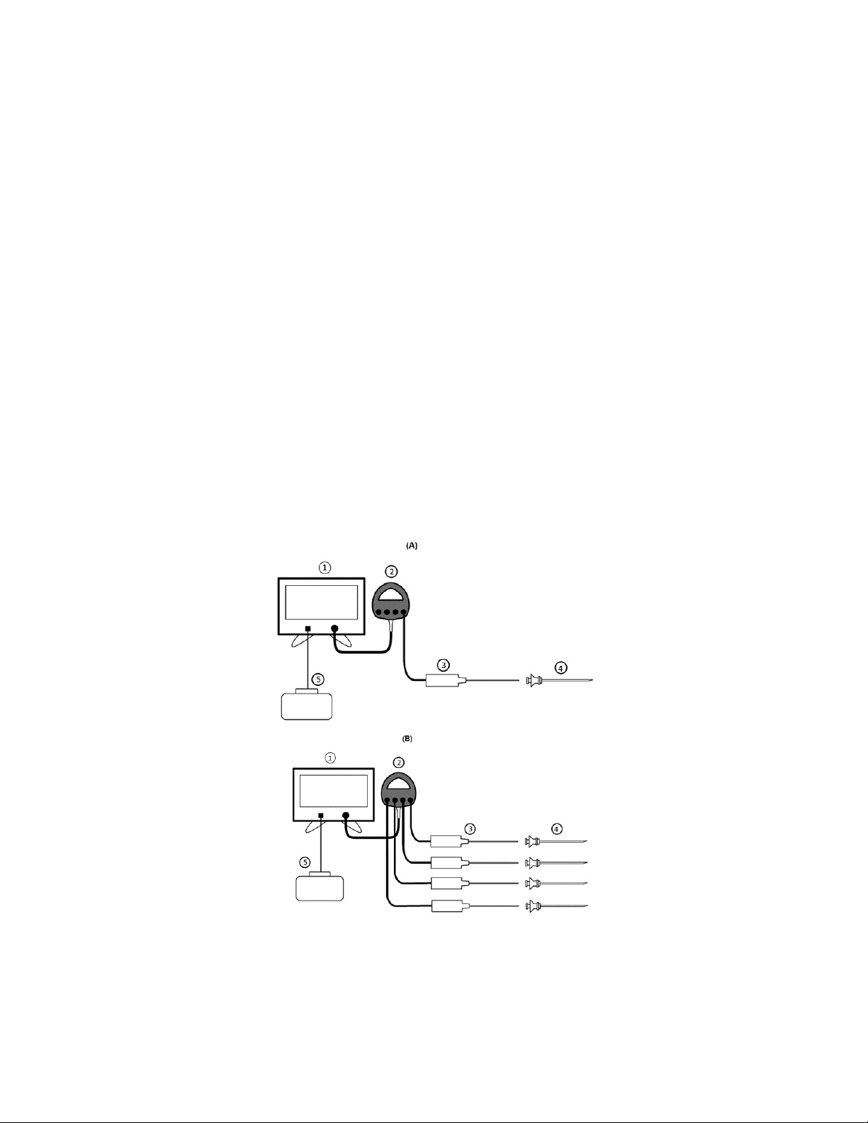
1. Assemble all required equipment for the intended procedure per Figure 1 or Figure 2.
Figure 1: Diagram of system connections in standard procedures. A) Connections for one probe and B) connections
for four probes.
ACCURIAN™ Radiofrequency GeneratorENGLISH9
Page 10

Figure 2: Diagram of system connections in enhanced procedures. A) Connections for one probe and B) connections
for four probes.
2. Perform a visual check on all equipment and ensure all components are in good working order. Do not use damaged
equipment.
Compatible Accessories
Tables 1 and 2 describe the compatible equipment with the Generator (1) for use in Standard (Figure 1) and Enhanced
(Figure 2) configurations.
Table 1: Accessories to be used with the Generator in Standard configuration.
Accessory/Applied Parts Part Classification Part Number(s)
ACCURIAN™ RF Generator with
Generator Desk Stand (1)
ACCURIAN™ Standard Connector Hub (2) N/A APH100
ACCURIAN™ Single-Use RF Probe(s) (3) Type CF (Defibrillation Proof
ACCURIAN™ Reusable RF Probe(s) (3) Type CF (Defibrillation Proof
ACCURIAN™ RF Cannula(e) (4)
Dispersive Electrode* (5) Type CF N/A
Table 2: Accessories to be used with the Generator in Enhanced configuration.
Accessory/Applied Parts Part Classification Part Number(s)
ACCURIAN™ RF Generator with Generator Desk Stand (1) N/A AG1000
N/A AG1000
APSD050, APSD100, APSD150
Applied Part)
APSR050, APSR100, APSR150,
Applied Part)
Type CF
APSN050, APSN100, and APSN150
AC0001, AC0002, AC0003, AC0004,
AC0005, AC0006, AC0007, AC0008,
AC0009, AC0010, AC0011, AC0012,
AC0013, AC0014, AC0015, AC0016,
AC0017, AC0018, AC0019, and AC0020
10ENGLISHACCURIAN™ Radiofrequency Generator
Page 11

Table 2: Accessories to be used with the Generator in Enhanced configuration.
Accessory/Applied Parts Part Classification Part Number(s)
ACCURIAN™ Pump Unit with Pump Desk Stand and Cable (2) N/A APH1000
ACCURIAN™ Enhanced Connector Hub (3) N/A APH200
ACCURIAN™ Enhanced RF
Probe (kit(s))
Dispersive Electrode* (7) Type CF N/A
*Disposable dispersive electrode meeting EN/IEC 60601-2-2, 2009 requirements for electrosurgical electrodes. No dispersive
electrode is provided as part of the ACCURIAN™ RF Ablation System, although the ValleyLab™ dispersive electrode E7507
has been validated for use with this system.
ACCURIAN™ Enhanced RF
Probe (4)
ACCURIAN™ Tube Kit (5) N/A
ACCURIAN™ Introducer (6) N/A
Type CF (Defibrillation
Proof Applied Part)
APSC01, APSC02,
APSC03, APSC04,
APSC05, and APSC06
When you get a New Generator
When you open the box, you will find:
ACCURIAN™ RF Generator
Hospital-grade power cords
• The Generator box will contain the US power cord;
• Three other power cords, for use in other countries, will also be provided.
ACCURIAN™ Generator Desk Stand
Preparing the Generator for Use
1. Inspect the Generator for any signs of damage to the display, metal trim, or rear panel. Also ensure all Generator labels
are present and legible. If any equipment or label damage is found, do not use the Generator. Contact Medtronic for
further instructions.
2. Inspect the power cord(s) for damage.
3. Check the mounting bracket on the back panel of the Generator to ensure it is firmly in place.
4. Ensure nothing is connected to the Generator prior to mounting.
5. Prepare the Generator Desk Stand. Do not use the Generator without mounting on a Desk Stand. Position stand on a
stable surface with a minimum 1 inch (2.54 centimeters) clearance around the stand base in close proximity to electrical
source.
Mounting the Generator
1. Lift the Generator so that the Generator mounting bracket is above the Generator Desk Stand mounting bracket.
2. Slide the Generator mounting bracket onto the Generator Desk Stand mounting bracket. Ensure the Generator is secure
(Figures 4, 5).
3. Do not adjust the position of the mounting bracket on the Generator Desk Stand.
4. Do not obstruct the vents underneath the Generator. Under continuous use for extended periods of time, it is normal for
the outer housing to be warm to the touch.
5. If applicable, the ACCURIAN™ Pump Unit should be mounted adjacent to the Generator on the ACCURIAN™ Pump
Desk Stand. Refer to the ACCURIAN™ Pump Unit IFU for Pump mounting instructions.
Powering on the Generator
1. Connect one end of the Generator power cord to the AC Power Inlet on the Generator and the other end to a power
source. Position the Generator so the power supply connection is easily accessible as a means of disconnecting power
from the Generator.
2. Locate the AC Mains Switch on the rear panel of the Generator. Flip the switch to
Startup, the LCD, LEDs and audible tones will be cycled. These should all be observed before using the Generator.
3. The Generator should enter the Device Connect mode at the completion of Startup.
to turn the Generator on. During
Standard Procedure Setup
1. When the Connect Hub screen is displayed, connect the ACCURIAN™ Standard Connector Hub. Refer to the Connector
Hub IFU for further instructions.
2. Connect the dispersive electrode to the Generator and ensure the dispersive electrode is applied to the patient properly.
Prepare the skin for application of the dispersive electrode, as described in the dispersive electrode IFU. Refer to the
dispersive electrode IFU for more information.
3. Follow the ACCURIAN™ RF Probe IFU to set up the remainder of the system.
ACCURIAN™ Radiofrequency GeneratorENGLISH11
Page 12

4. If interference with an instrument outside of the system is suspected, resolve interference prior to proceeding.
5. Once the system is set up and all probes are connected, pressing the Output ON/OFF button places the system in
Sensory Stimulation Ready state, as indicated by the Output ON/OFF button illumination, auditory tone and highlighted
selected channel on the RF Generator screen.
6. Once the Generator has entered the Sensory Stimulation Ready State, probe(s) connected to the Standard Connector
Hub can be correlated by matching the probe connector letter on the hub (A, B, C, or D) to the corresponding channels on
screen (A, B, C, or D).
Enhanced Procedure Setup
1. When the Connect Hub screen is displayed, connect the ACCURIAN™ Enhanced Connector Hub. Refer to the Connector
Hub IFU for further instructions.
2. Follow the ACCURIAN™ Pump Unit IFU to set up the Pump Unit.
3. Perform the following checks before the procedure:
Inspect the ACCURIAN™ Pump Unit, ACCURIAN™ Pump Desk Stand, ACCURIAN™ Pump Cable, and power cord
for damage.
Inspect the ACCURIAN™ Pump Unit to verify all labels are present and legible. Contact Medtronic if any equipment or
label damage is found. Do not use damaged equipment.
4. Follow the ACCURIAN™ Enhanced Kit IFU to set up the remainder of the system.
5. If interference with an instrument outside of the system is suspected, resolve interference prior to proceeding.
Once system is set-up, and all probes are connected, pressing the Output ON/OFF button places the system in Sensory
Stimulation Ready State, as indicated by the Output ON/OFF button illumination, auditory tone and highlighted selected
channel on the RF generator screen. Once the Generator has entered the Sensory Stimulation Ready State, probe(s)
connected to the Enhanced Connector Hub can be correlated by matching the probe connector letter on the hub (A, B, C, or
D) to the corresponding channels on screen (A, B, C, and D).
Treatment Modes
Sensory Stimulation, Motor Stimulation, Lesion, and Pulsed are the modes that are accessible when connecting a standard
connector hub. Sensory Stimulation, Motor Stimulation, and Enhanced Lesion are the modes that are accessible when
connecting the Enhanced Connector Hub. Each procedure can be started and stopped by pressing the Output ON/OFF
button. During the procedure, progress can be monitored on the Generator display. The following options are available for
each mode:
a) Sensory/Motor Stimulation: After pressing the Output ON/OFF button, amplitude of stimulation can be adjusted by
pressing buttons or turning the touchscreen dial.
b) Lesion: Temperature, power, impedance, and procedure time are displayed during each procedure. The operator can
select between bipolar and monopolar procedures by pressing the Bipolar buttons. The operator can adjust Set Temp and
Duration for each channel before and during procedures.
c) Pulsed: Temperature, voltage, impedance, and procedure time are shown during each procedure. The operator can
select between bipolar and monopolar procedures by pressing the Bipolar buttons. The operator can adjust Voltage Limit
and Duration for each channel before and during procedures.
d) Enhanced Lesion: Temperature, power, impedance, and procedure time are displayed during each procedure. The
operator can select between bipolar and monopolar procedures by pressing the Bipolar buttons. The operator can adjust
Set Temp and Duration for each channel before and during procedures. At the start of each procedure the pumps will
circulate water for a number of seconds before RF delivery begins.
If a warning or error occurs at any time, a message will appear on the display along with instructions for resolution.
In all modes, the operator can access additional treatment options, as well as procedure logs and reports, by selecting the
Settings button.
Shutdown Procedure
1. Turn off the mains power using the AC Mains Switch on the rear panel of the Generator. Flip the switch to to turn off.
Ensure the LCD turns off.
2. Disconnect the Generator power cord from the mains and the AC Power Inlet on the Generator.
3. Disconnect the Connector Hub and, if applicable, the Pump Connector Cable.
Generator Cleaning Instructions
Use a solution of 70% isopropyl alcohol (IPA) applied with a cloth to clean the Generator rear cover, front panel, and
power cable. The Generator cannot be sterilized. Do not allow fluids to enter the chassis.
Do not spray or pour liquids directly on the Generator.
Flammable agents used for cleaning, or as solvents or adhesives, should be allowed to evaporate before operation.
Generator Maintenance Schedule
The Generator verifies calibration integrity during POST. Maintenance is not required.
12ENGLISHACCURIAN™ Radiofrequency Generator
Page 13

For cleaning instructions, refer to the previous section.
USER INTERFACE
Front Panel Display, Controls, and Connections
The Operator is expected to be positioned in front of the Generator, so the display is accessible and legible. The patient is
expected to be positioned so the Operator is able to view the display during treatment.
Figure 3: Front Panel
1. Touchscreen Window:
Display messages (e.g. errors, faults, settings, profiles, current mode) and allows the user to interact with the device
through the touchscreen.
Each key press should result in an audible tone.
If a system fault occurs, the Generator will enter Fault Mode. Power to the system must be cycled (OFF-ON) to attempt
recovery from a system fault.
Windows for Probes A, B, C, and D are displayed from left to right and correlate with the Connector Hub ports which
are labelled A, B, C, and D.
In Figure 3, the Lesion Ready State is displayed on the screen.
2. Sensory, Motor, Lesion, and Pulsed buttons (2): used to access the different modes accessible with the ACCURIAN™
Standard Connector Hub. If the ACCURIAN™ Enhanced Connector Hub is connected, Enhanced Lesion, Sensory
Stimulation, and Motor Stimulation Modes will be accessible.
3. Help button (3): button pressed to enter the Help Mode. The Help screen that initially appears will be tailored to the mode
from which Help Mode was entered. However, the user will also be able to access Help screens applicable to all other
modes.
4. Settings button (4): button pressed to enter and modify Procedure Settings and Generator Settings.
5. Default button (5): button pressed to enter the profile manager mode where user profiles can be viewed, saved, and
loaded.
6. Reset button (6): button pressed to exit the Procedure Complete State for the Lesion, Enhanced Lesion, and Pulsed
Modes.
7. Measurements Window (7):
Measured values for elapsed procedure time, probe temperature, power being delivered, and impedance are displayed
for each channel in Lesion Mode.
Probe lengths and 3-digit serial numbers are displayed for all connected probes. These serial numbers match serial
numbers printed on the probe to allow the user to quickly and easily determine which probe corresponds to which
channel on screen.
8. Bipolar buttons (8): allow probes to be switched between monopolar and bipolar configurations.
9. Graph Window (9):
Used for graphing temperature and power data acquired during RF output in the Lesion Active State.
Channel-specific stop buttons are available.
10. Modifiable Parameters Window (10):
Set temp modifier: allows set temp to be modified channel-specifically before and during procedures.
Duration modifier: allows procedure duration to be modified channel-specifically before and during procedures.
11. Output ON/OFF Indicator (11):
ACCURIAN™ Radiofrequency GeneratorENGLISH13
Page 14

LED around the Output ON/OFF button will be blue whenever RF is being delivered.
LED around the Output ON/OFF button will be white whenever stimulation is being delivered.
Otherwise, the indicator will be off.
12. Output ON/OFF button (12): to start and stop stimulation and RF procedures.
13. Dispersive Electrode Port (13): patient-isolated connection for attachment of a dispersive electrode.
14. Connector Hub Connection (14): patient-isolated connection for attachment of either the ACCURIAN™ Standard
Connector Hub or ACCURIAN™ Enhanced Connector Hub.
15. Front USB Port (15): allows for a USB flash drive to be connected for updating software and downloading procedure logs
and PDF reports. USB flash drives should only be used in this Front USB Port. This port is only intended for use with the
following USB drives:
SanDisk Cruzer Blade™ 16GB
SanDisk Cruzer Blade™ 32GB
SanDisk Cruzer Blade™ 64GB
Rear Panel, Controls, and Connections
Figure 4: Back panel
1. Fuse Drawer (1): houses the fuses and allows for AC input voltages of 100-240 V.
2. AC Mains Switch (2): controls the initial AC power input. If the power is connected to the AC Power Inlet, flip the switch to
to turn the Generator ON. Flip the switch to to turn the Generator OFF.
3. AC Power Inlet (3): AC power cord is connected to the inlet to supply power to the system.
4. Equipotential Ground Connection (4): This connector is attached to the chassis/earth ground and is intended for earth
reference connection in environments where equipotential ground cabling is used.
5. Generator Mounting Bracket (5): for mounting to the ACCURIAN™ Generator Desk Stand.
Figure 5: Brackets for the Generator and Pump onto the Generator Desk Stand and Pump Desk Stand
6. Device Labels (6): indicates the model number of the Generator, Medtronic contact information, and serial number.
7. USB Ports (7): intended for connection of the Generator to the ACCURIAN™ Pump Unit through the ACCURIAN™ Pump
Connector Cable. The ACCURIAN™ Pump Connector Cable is provided with the ACCURIAN™ Pump Unit.
8. Footswitch Connection (8). (A footswitch is not provided as part of the ACCURIAN™ RF Ablation System).
9. HDMI Port (9): the Generator will allow connection of an external monitor via an HDMI v1.4 connection. If an external
monitor is used, it should be a hospital grade monitor or placed outside the reach of the patient and operator.
Touchscreen Calibration
1. Touchscreen Calibration can be entered through a two second touchscreen press during Startup (when the progress bar
is displayed) or through Generator Settings. The two second press is provided as an alternative in case the touchscreen
is miscalibrated.
14ENGLISHACCURIAN™ Radiofrequency Generator
Page 15

2. After entering Touchscreen Calibration, instructions on screen indicate to press each button as it becomes enabled.
3. Once each button is pressed, the next button will appear. After the operator has pressed 5 buttons (one in each corner of
the window and one in the center), the Generator will display a message prompting the operator to accept the calibration.
If the operator does not accept the calibration within 10 seconds, the calibration will be discarded.
4. After the operator accepts the calibration or the 10 seconds elapses, the Generator will return to its previous state.
Frequently Used Functions
Table 3: Frequently used functions
Function Section
Generator AC Power Switch activations Rear Panel, Controls, and Connections: AC Mains Switch
Connecting/disconnecting Connector Hub to/from
Generator
Connecting/disconnecting Pump to/from Generator Rear Panel, Controls, and Connections: USB Ports
Connecting/disconnecting Dispersive Electrode to/from
Generator
Connecting/disconnecting Monitor to/from Generator Rear Panel, Controls, and Connections: HDMI Port
Connecting/disconnecting ACCURIAN™ Standard or
Enhanced Probe(s) to/from Connector Hub
Reading Generator display (impedance, voltage,
temperature, power, procedure time, graphs, alerts, etc.)
Switching between monopolar and bipolar configurations
in Lesion, Pulsed and/or Enhanced Lesion
Pressing the Output ON/OFF button Front Panel Display, Controls, and Connections: Output ON/OFF
Navigating between Sensory Stimulation, Motor
Stimulation, Pulsed, and Lesion Modes
Pressing touchscreen buttons Front Panel Display, Controls, and Connections: Touchscreen
Cleaning Generator Cleaning Instructions
Front Panel Display, Controls, and Connections: Connector Hub
Connection
Front Panel Display, Controls, and Connections: Dispersive
Electrode Port
Refer to the ACCURIAN™ Standard Probe or ACCURIAN™
Enhanced Probe IFU
Front Panel Display, Controls, and Connections: Modifiable
Parameters Window
Front Panel Display, Controls, and Connections: Bipolar buttons
button
Front Panel Display, Controls, and Connections: Sensory, Motor,
Lesion, and Pulsed buttons
Window
TECHNICAL SPECIFICATIONS
Compliant Standards
EN/IEC 60601-1, 2005 + A1 2012
EN/IEC 60601-1-2, 2014
EN/IEC 60601-2-2, 2009
EN/IEC 60601-1-6, 2010 + A1 2013
Impedance Measurement
Range 25 to 3000 with 1 resolution.
Low Power Impedance Measurement delivers less than 10.0mW as averaged over any 1 s period.
Low Power Impedance Measurement utilizes the same frequency as the RF output.
No greater than 25 V
Low Power Impedance Measurement provides impedance reading at least once every 0.1s.
is applied to the RF Load during Low Power Impedance Measurement.
RMS
RF/Stimulation Output
RF energy: 465.1 kHz ± 3%, Quasi-sinusoidal voltage waveform with harmonic content < -15 dBc.
Maximum power: 50W (into an impedance range of 50 - 500). Outside this range, the Generator reduces
available power to comply with specified voltage and current limits.
Stimulation (Voltage controlled) Maximum voltage: 10.0V ± 10%
Maximum current: 30.0mA ± 10%
Stimulation (Current controlled) Maximum current: 10.0mA ± 10%
Maximum voltage: 10.0V ± 10%
Applied part of patient circuit is not referenced to earth at high frequency.
The maximum output of 50 W is restricted by:
Maximum Voltage: 160V
RMS
ACCURIAN™ Radiofrequency GeneratorENGLISH15
Page 16

Maximum current: 1.0A
Phase Angle: Between -90º (capacitive) and +30º (inductive)
RMS
Power output is available into loads of 25 - 3000
200 is the nominal “rated” load.
Measurement Accuracy (at time of manufacture)
Power:
Impedance = 25 – 99 ± 15% or ± 1W, whichever is greater
Impedance = 100 – 500 ± 5% or ± 1W, whichever is greater
Impedance = 501 – 1000 ± 8% or ± 1W, whichever is greater
Impedance = 1001 – 3000 ± 20% or ± 1W, whichever is greater
Voltage:
Impedance = 25 – 99 ± 15% or ± 2V, whichever is greater
Impedance = 100 – 500 ± 5% or ± 2V, whichever is greater
Impedance = 501 – 1000 ± 7% or ± 1V, whichever is greater
Impedance = 1001 – 3000 ± 15% or ± 1V, whichever is greater
Impedance:
25 – 99 ± 10% or ± 5, whichever is greater
100 – 500 ± 5%
501 – 1000 ± 8%
1001 – 3000 ± 20%
Temperature: ± 3°C between 15°C and 105°C
Elapsed Time: ± 1 s/min
Software Shutdown Limits During RF/Stimulation Delivery
Measured Impedance: < 25 or > 3000
Measured Temperature: < 15°C or > 105°C
Measured RF Power: > 50W
Measured RF Voltage: > 160V
Measured RF Current: > 1.0A
RMS
RMS
Hardware Shutdown Limits
Measured RF Power: > 80W
Measured RF Voltage: > 190V
Measured RF Current: > 1.2A
RMS
RMS
Mechanical Specifications
Size: 411mm x 292mm x 107mm
Weight: 17lb (7.7kg) maximum (not including power cord, Generator Desk Stand or
shipping box)
Moisture protection rating: IPX0 (ordinary, per IEC601)
Environmental Specifications
Operational temperature: 10°C to 40°C
Operational relative humidity: 30% - 70%
Transport and Storage temperature: -20°C to 60°C
Transport and Storage relative humidity: 20% to 95% non-condensing
Operational altitude: Up to 3000m
16ENGLISHACCURIAN™ Radiofrequency Generator
Page 17

After being stored, and then undergoing a 2 hour acclimation period in the operating environment, the Generator will operate
within the safety and performance specifications.
Fuses
100 – 240V~ / 50-60 Hz configuration: Replace mains fuses as marked:
5A/250V, T-lag, 5 x 20 mm
When replacing fuses:
a) Ensure the integrity of the new fuses by inspecting for damage that could affect the function.
b) Use a slot drive screwdriver to remove the fuse drawer.
c) Replace the fuses and close the fuse drawer.
Line Input Ratings
The system operates from an AC source ranging from 100 to 240V
The system operates from an AC source with a frequency of 50/60Hz.
The system operates from a rated input current of 2.5A.
The system operates from an AC source capable of up to 300W.
RMS
.
Rated Accessory Voltage (for associated equipment and active accessories)
160 V
for each active compatible accessory.
RMS
Disposal Instructions
Do not dispose of in waste. Recycle in compliance with electronic recycling requirements.
Alert Limits
The alert limits during RF and stimulation delivery are as follows:
A Low Priority Alert indication is raised if measured impedance exceeds 3000.
A Low Priority Alert indication is raised if measured impedance drops below 25.
A Low Priority Alert indication is raised if measured temperature exceeds 105°C.
A Low Priority Alert indication is raised if measured temperature drops below 15°C.
Alert Tones
When a Low Priority Alert indication is raised, the Generator will sound the Low Priority Alert Tone. A Low Priority Alert
tone consists of a single Alert Pulse.
When a Medium Priority Alert indication is raised, the Generator will sound the Medium Priority Alert tone. A Medium
Priority Alert tone consists of a single Alert Pulse repeated every 4-5 seconds.
Alert Tone volumes are always greater than 40dBA and less than 90dBA.
Alert Condition Logging
The Generator logs the occurrence and identity of alert conditions. The log file is maintained when the alert is acknowledged,
and the system is powered down.
Fault State
If a non-recoverable fault is encountered, the Generator will enter a Fault State. The Fault State will display a fault code and
basic instructions to the operator. Follow the instructions provided on screen. A Medium Priority Alert tone will play in the Fault
State. Mains power to the Generator must be cycle (OFF-ON) to attempt recovery from a fault.
FURTHER INFORMATION
If you have any problems with or questions about Medtronic equipment, contact Medtronic.
LIMITATION OF LIABILITY
In no event shall Medtronic be liable for any direct, indirect, incidental, consequential, or exemplary damages arising out of or
in connection with the ACCURIAN™ RF Generator based upon breach of contract (including breach of warranty).
IEC EMC SPECIFICATIONS (EMISSIONS)
Table 4: Guidance and manufacturer’s declaration – electromagnetic emissions.
The Generator is intended for use in the electromagnetic environment specified below. The user of the Generator
should assure that it is used in such an environment.
Emissions test Compliance Electromagnetic environment – guidance
RF emissions CISPR 11 Group 1 The Generator uses RF energy only for its internal function. Therefore, its RF
emissions are very low and are not likely to cause any interference in nearby
electronic equipment.
ACCURIAN™ Radiofrequency GeneratorENGLISH17
Page 18

Table 4: Guidance and manufacturer’s declaration – electromagnetic emissions.
The Generator is intended for use in the electromagnetic environment specified below. The user of the Generator
should assure that it is used in such an environment.
Emissions test Compliance Electromagnetic environment – guidance
RF emissions CISPR 11 Class A
Harmonic emissions
IEC 61000-3-2
Voltage fluctuations/flicker
Class D
Complies
The Generator is suitable for use in all establishments, including domestic
establishments and those directly connected to the public low voltage power
supply network that supplies buildings used for domestic purposes.
emissions
IEC 61000-3-3
IEC EMC SPECIFICATIONS (IMMUNITY)
Essential performance was shown to be maintained for all levels of electromagnetic immunity testing. Essential performance
for this system includes accurate temperature measurement during lesion delivery, accurate measurement of RF power
levels, accurate measurement of stimulation delivery levels, and control of the pump during enhanced lesion delivery.
A degradation in essential performance will generally always be prevented by an alert or error associated with that function. In
the unlikely event that an alert or error does not prevent degradation of essential performance by an electromagnetic
disturbance, one or more aspects of essential performance, as defined above, may be impacted.
Table 5: Guidance and manufacturer’s declaration – electromagnetic immunity
The Generator is intended for use in the electromagnetic environment specified below. The customer or the user of
the Generator should assure that it is used in such an environment.
Immunity test IEC 60601 test level Compliance level Electromagnetic environment -
guidance
Electrostatic discharge
(ESD)
IEC 61000-4-2
Electrical fast transient/
burst
IEC 61000-4-4
Surge
IEC 61000-4-5
Voltage dips, short
interruptions, and
voltage variations on
power supply input lines
IEC 61000-4-11
Power frequency (50/60
Hz) magnetic field
IEC 61000-4-8
Note: U
is the AC mains voltage prior to application of the test level.
T
± 8kV contact
±2kV, ±4kV, ±8kV, ±15kV
air
±8kV contact
±2kV, ±4kV, ±8kV, ±15kV air
Floors should be wood, concrete, or
ceramic tile. If floors are covered with
synthetic material, the relative
humidity should be at least 30%.
±2kV for power supply lines
±1kV for input/output lines
Both at 100kHz repetition
frequency
For power supply lines:
±0.5kV and ± 1kV line(s) to
line(s)
±0.5kV, ±1kV, and ±2kV
line(s) to ground
For signal input/output
ports:
±2kV for power supply lines
±1kV for input/output lines
Both at 100kHz repetition
frequency
For power supply lines:
±0.5kV and ± 1kV line(s) to
line(s)
±0.5kV, ±1kV, and ±2kV
line(s) to ground
For signal input/output ports:
±2kV line(s) to ground
Mains power quality should be that of
a typical commercial or hospital
environment.
Mains power quality should be that of
a typical commercial or hospital
environment.
±2kV line(s) to ground
0% U
for 0.5 cycle at:
T
0°, 45°, 90°, 135°, 180°,
225°, 270°, and 315°
0% U
for 1 cycle
T
and
70% U
0% U
for 25/30 cycles
T
for 250/300 cycles
T
for 0.5 cycle at:
0% U
T
0°, 45°, 90°, 135°, 180°, 225°,
270°, and 315°
0% U
for 1 cycle
T
and
70% U
0% U
for 25/30 cycles
T
for 250/300 cycles
T
Mains power quality should be that of
a typical commercial or hospital
environment. If the user of the
Generator requires continued
operation during power mains
interruptions, it is recommended that
the Generator be powered from an
uninterruptible power supply.
30 A/m 30 A/m Power frequency magnetic fields
should be at levels characteristic of a
typical location in a typical commercial
or hospital environment.
18ENGLISHACCURIAN™ Radiofrequency Generator
Page 19
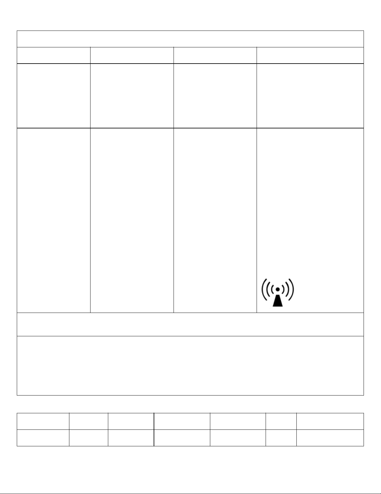
Table 6: Guidance and manufacturer’s declaration – electromagnetic immunity
The Generator is intended for use in the electromagnetic environment specified below. The customer or the user of
the Generator should assure that it is used in such an environment.
Immunity test IEC 60601 test level Compliance level Electromagnetic environment -
guidance
Conducted disturbances
induced by RF Fields
IEC 61000-4-6
3V
0.15MHz – 80MHz
6V
ISM bands between
0.15MHZ and 80MHZ
80% AM at 1kHz
3V
0.15MHz – 80MHz
6V
ISM bands between
0.15MHZ and 80MHZ
80% AM at 1kHz
Portable and mobile RF
communications equipment should
be used no closer to any part of the
ACCURIAN™ Radiofrequency
Generator, including cables, than the
recommended separation distance
calculated from the equation
applicable to the frequency of the
transmitter.
Radiated RF
IEC 61000-4-3
3 V/m
80MHz to 2.7GHz
80% AM at 1kHz
Specific communication
frequencies tested per table
3
3 V/m
80MHz to 2.7GHz
80% AM at 1kHz
Specific communication
frequencies tested per table
3
Recommended separation distance:
d = [1.17] P
d = [1.17] P 80MHz to 800MHz
d = [2.33] P 800MHz to 2.5GHz
where P is the maximum output
power rating of the transmitter in
watts (W) according to the transmitter
manufacturer and d is the
recommended separation distance in
meters (m).
Field strengths from fixed RF
transmitters, as determined by an
electromagnetic site survey,
a
should
be less than the compliance level in
each frequency range.
b
Interference may occur in the vicinity
of equipment marked with the
following symbol:
Note 1: at 80MHz and 800MHz, the higher frequency range applies.
Note 2: These guidelines may not apply in all situations. Electromagnetic propagation is affected by absorption and reflection
from structures, objects, and people.
a
Field strengths from fixed transmitters, such as base stations for radio (cellular/cordless) telephones, and land mobile
radios, amateur radio, AM and FM radio broadcast and TV broadcast cannot be predicted theoretically with accuracy. To
assess the electromagnetic environment due to fixed RF transmitters, an electromagnetic site survey should be considered.
If the measured field strength in the location in which the ACCURIAN™ Radiofrequency Generator including cables or any of
its components are used exceeds the applicable RF compliance level above, the ACCURIAN™ Radiofrequency Generator
including cables should be observed to verify normal operation. If abnormal performance is observed, additional measures
may be necessary, such as re-orienting or relocating the entire ACCURIAN™ Radiofrequency Generator including cables.
b
Over the frequency range 150kHz to 80MHz, field strengths should be less than 3 V/m.
Table 7: Enclosure port immunity levels to RF wireless communications equipment
Test Frequency
(MHz)
Band
(MHz)
Service Modulation Maximum Power
385 380 - 390 TETRA 400 Pulse modulation
18Hz
(W)
Distance
(m)
Immunity Test Level
(V/m)
1.8 0.3 27
ACCURIAN™ Radiofrequency GeneratorENGLISH19
Page 20
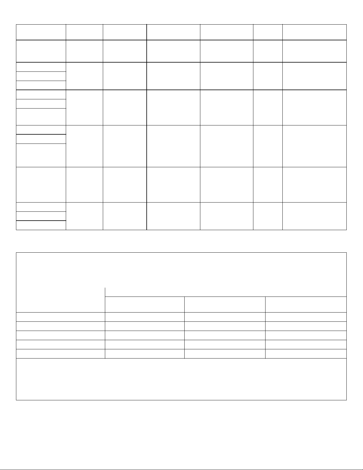
Table 7: Enclosure port immunity levels to RF wireless communications equipment
Test Frequency
(MHz)
450 430 - 470 GMRS 460,
710 704 - 787 LTE Band 13,17Pulse modulation
745
780
810 800 - 960 GSM 800/900,
870
930
1720 1700 - 1990 GSM 1800,
1845
1970
2450 2400 - 2570 Bluetooth,
5240 5100 - 5800 WLAN 802.11
5500
5785
Band
(MHz)
Service Modulation Maximum Power
GM
FRS 460
TETRA 800,
iDEN 820,
CDMA 850,
LTE Band 5
CDMA 1900,
GSM 1900,
DECT;
LTE Band 1, 3
4, 25; UMTS
WLAN,
802.11 b/g/n,
RFID 2450,
LTE Band 7
a/n
±5kHz deviation
1kHz sine
217 Hz
Pulse modulation
18 Hz
Pulse modulation
217 Hz
Pulse modulation,
217 Hz
Pulse modulation
217 Hz
Distance
(W)
20.328
0.2 0.3 9
20.328
20.328
20.328
0.2 0.3 9
(m)
Immunity Test Level
(V/m)
Table 8: Recommended separation distances between portable and mobile RF communications equipment and the
The Generator (including cables) is intended for use in an electromagnetic environment in which radiated RF
disturbances are controlled. The customer or the user of the Generator (including cables) can help prevent
electromagnetic interference by maintaining a minimum distance between portable and mobile RF communications
equipment (transmitters) and the Generator (including cables) as recommended below, according to the maximum
output power of the communications equipment.
Rated maximum output power
of transmitter
0.01 0.12 0.12 0.23
0.1 0.37 0.37 0.74
1 1.17 1.17 2.33
10 3.69 3.69 7.38
100 11.7 11.7 23.3
For transmitters rated at a maximum output power not listed above, the recommended separation distance d in meters (m)
can be estimated using the equation applied to the frequency of the transmitter, where P is the maximum output power rating
of the transmitter in watts (W) according to the transmitter manufacturer.
Note 1: at 80MHz and 800MHz, the separation distance for the higher frequency range applies.
Note 2: these guidelines may not apply in all situations. Electromagnetic propagation is affected by absorption and reflection
from structures, objects, and people.
Separation distance according to frequency of transmitter (m)
150kHz to 80MHz
d = [1.17] √P
Generator including cables
80MHz to 800MHz
d = [1.17] √P
800MHz to 2.5GHz
d = [2.33] √P
20ENGLISHACCURIAN™ Radiofrequency Generator
Page 21
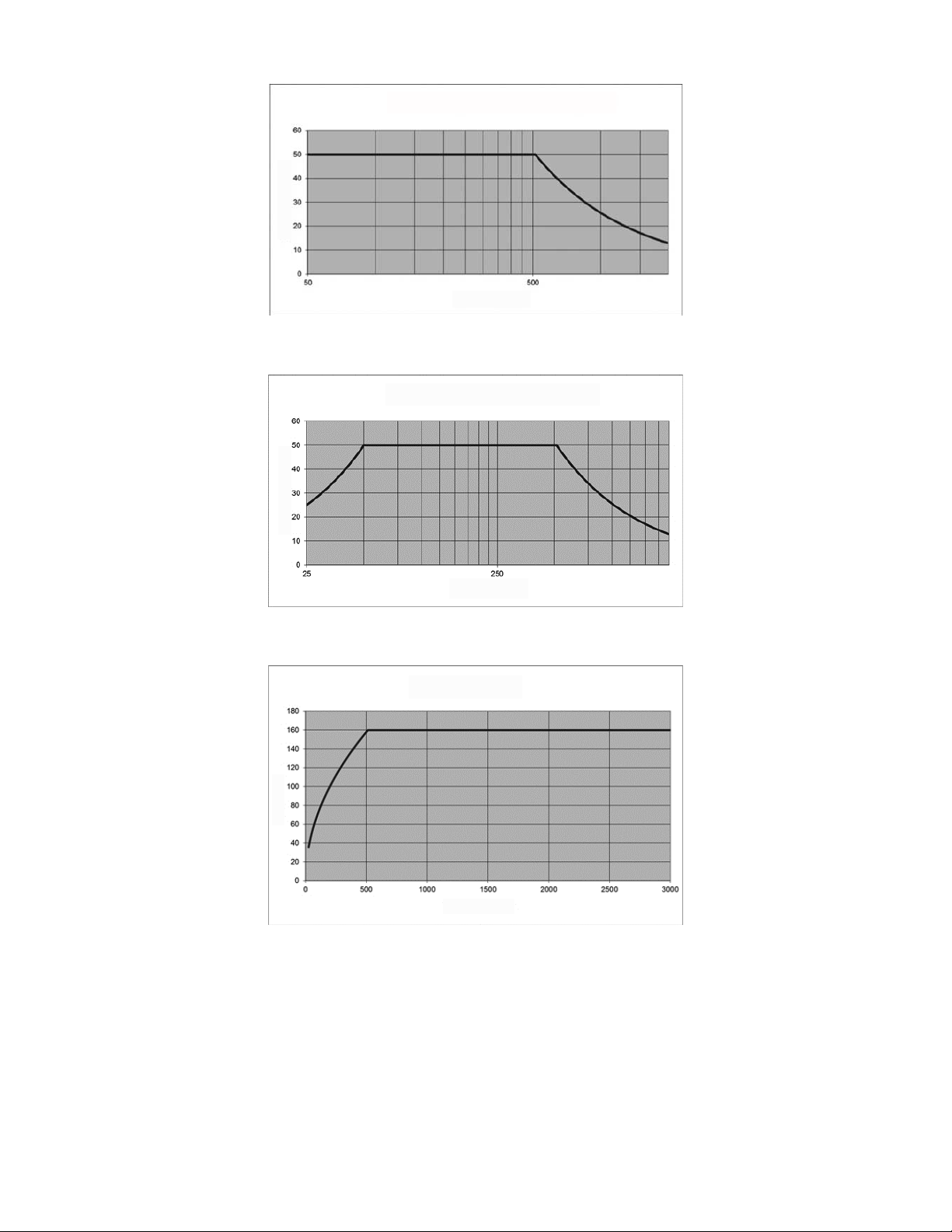
Figure 6: Monopolar Power (Y) vs. Load Impedance (X)
[Maximum Monopolar Power- Continuous Operation]
Y
X
Figure 7: Bipolar Power VA (Y) vs. Load Impedance (X)
[delivery is prevented below 25 ohms]
Y
X
Figure 8: Voltage (Y) vs. Impedance (X)
[monopolar and bipolar]
Y
X
ACCURIAN™ Radiofrequency GeneratorENGLISH21
Page 22
Medtronic Sofamor Danek USA, Inc.
1800 Pyramid Place
Memphis, TN 38132
Telephone: 800 933 2635 (USA)
901 396 3133 (Outside USA)
Fax: 901 396 0356
Medtronic B.V.
Earl Bakkenstraat 10
6422 PJ Heerlen
The Netherlands
Tel: + 31 45 566 80 00
©2018 Medtronic Sofamor Danek USA, Inc. All rights reserved.
M708348B803 Rev. A
 Loading...