

Page 1
MIDAS REX® MR7
Pneumatic High-Speed System
Instruction Manual
Rx Only
Page 2

Page 3

Symbols
Lubricant/Diuser
Attachment
STERILE
Control Unit
REGULATOR
Brush
|
EC REP
The following symbols may appear within this manual, on product labeling, or on the product itself:
Attention, see Instructions for Use. Tube Control
United States federal law restricts this
device to sale by or on the order of a
physician.
Reference Number Use with
Lot Number Multi-Use Disposable
Serial Number
Quantity
For single patient use only. Do not
re-use, re-process, or re-sterilize this
product. Re-use, re-processing or
re-sterilization may compromise the
structural integrity of the device and/
or create a risk of contamination of the
device, which could result in patient
injury, illness, or death.
Approximately equal to
Non-Sterile
Sterilized by Gamma Irradiation
Instrument Case
Dissecting Tool
Refurbished
Air Pressure Relief
Attachment
Instrument Case
Lubricant/Diffuser
Dissecting Tool
Attachment
Control Unit
Refurbished
Use by date
Accessory
Accessory
Date of manufacture
Temperature Limitations
Unlock
Lock
On
Off USA Only
Finger-Operated Control Manufacturer
Foot-Operated Control Do not dispose to unsorted
Compliant with European Council
Directive MDD 93/42/EEC.
Bone Mill
MOTOR
Adapter
Regulator
Bone Mill
Motor
Brush
Adapter
municipal waste.
Tool Control
Authorized Representative in the
European Community
Consult Instructions for Use
Page 4

Contents
General Information ...........................................................................................................................1
Indications for Use .............................................................................................................................. 1
Contraindications ....................................................................................................................1
Special Notices .........................................................................................................................1
General Safety Precautions .....................................................................................................2
No Latex Policy ........................................................................................................................2
System Components ...........................................................................................................................3
Non-Disposable Components ...............................................................................................3
Disposable Components .........................................................................................................8
Legend® Dissecting Tools ........................................................................................................9
General Guidelines For Attachment and Tool Applications ........................................... 10
Setting up the Operating Room ..................................................................................................... 13
Power Source Requirements ............................................................................................... 13
Pneumatic Connections....................................................................................................... 13
Setting up the MR7 System ............................................................................................................. 14
Installing the Oiler Cartridge .............................................................................................. 14
Connecting the Motor ......................................................................................................... 15
Installing an Attachment and Tool ................................................................................................ 16
Straight Attachments ............................................................................................................ 16
Specialized Attachments ...................................................................................................... 16
Activating the Motor ....................................................................................................................... 17
Disassembling the MR7 System ..................................................................................................... 18
Depressurize the System ...................................................................................................... 18
Disconnect Hoses ................................................................................................................. 18
Discard the Lubricant/Diuser Cartridge ......................................................................... 18
Remove the Attachment and Tool ...................................................................................... 18
Cleaning & Sterilizing the MR7 System ........................................................................................ 19
MR7 Motor ............................................................................................................................ 19
Legend Attachments / Tubes ............................................................................................... 20
i
Page 5

MR7 Pneumatic Control Unit / Regulator Hose /
Triton Adapter / Instrument Case ...................................................................................... 22
Transmissible Spongiform Encephalopathies (TSE) Return Policy............................... 22
Troubleshooting ............................................................................................................................... 23
Refurbishing or Repairs .................................................................................................................. 26
Preventative Maintenance ............................................................................................................... 27
Limited Warranty ............................................................................................................................. 28
Appendix A—Specialized Attachments ........................................................................................ 29
Angled Attachments ............................................................................................................. 29
Angled Double Lock Attachments ..................................................................................... 30
Curved Bur Attachments ..................................................................................................... 32
Variable Exposure Attachments ......................................................................................... 33
Footed Attachments ............................................................................................................. 33
Rotating Footed Attachments ............................................................................................. 34
Contra-Angle Attachment (16-MF) ................................................................................... 35
Metal Cutting Attachments ................................................................................................. 36
Telescoping Attachments ..................................................................................................... 37
Perforator Driver Attachments ........................................................................................... 38
Jacobs® Chuck Attachments ................................................................................................ 39
Bone Mill Attachment .......................................................................................................... 40
ii
Page 6

General Information
Read and understand this manual before use of the MR7 System.
The Midas Rex® MR7 system is designed for use by medical professionals familiar with powered surgical instrumentation.
The surgeon is responsible for learning the proper techniques in the use of this system, as inappropriate use may potentially
be harmful. It is strongly recommended that the surgeon and dedicated operating room personnel are knowledgeable with
the use of this equipment by being trained in Medtronic Midas Rex Hands-On Workshops or by one of the local authorized
representatives.
The MR7 system consists of the following components:
• MR7 or MR7 Touch Motor
• MR7 Pneumatic Control Unit with Various Connectors
• MR7 Regulator Hose
• MR7 Lubricant/Diuser Cartridge
• MR7 Triton® Adapter (optional)
• Legend® Attachments*
• Legend® Dissecting Tools*
*The MR7 system uses the same attachments and dissecting tools as the Legend® Pneumatic High-Speed System.
Indications for Use
The Medtronic Midas Rex MR7 System is a pneumatically operated surgical instrument system. The pneumatic motors
provide power to operate removable rotating surgical cutting tools and their accessories intended for use in neurosurgery,
including craniotomy and spinal surgery; as well as Ear, Nose and Throat (ENT), orthopedic and general surgical applications
including maxillofacial, craniofacial and sternotomy surgeries.
General Information
Contraindications
None
Special Notices
The words warning, caution and note have special meanings in this manual, and should be carefully reviewed:
WARNING: A warning indicates that the personal safety of the patient or physician may be involved. Disregarding this
information could result in injury to the patient or physician.
CAUTION: A caution indicates that there is a risk of damaging equipment.
NOTE: A note is intended to provide additional information, which may be useful, but is not essential to complete the
procedure.
1
Page 7

General Information
General Safety Precautions
WARNINGS:
• Do not use the Midas Rex MR7 System before proper cleaning and sterilization.
• Do not operate the Midas Rex MR7 System in the presence of Magnetic Resonance Imaging devices.
• Do not use damaged, faulty, or modied Midas Rex MR7 System components. Inspect the Midas Rex MR7 System for
damage prior to each use:
• Check the motor’s exhaust hose for cracks or tears.
• Visually inspect attachments and tools. Do not use bent or damaged tools.
• Install attachment and dissecting tool, then briey run motor.
• Do not operate the Midas Rex MR7 System without eye protection.
• Motors and attachments which fail due to extended use may allow a component to detach and fall from the motor or
attachment, and may cause patient injury.
* Check motor for overheating and leaking lubricant.
* Check attachment for overheating.
* Check dissecting tool for ail.
• Heavy side loads and/or long operating periods may cause the device to overheat. If overheating occurs:
• Never place an overheated motor on the patient or draping during surgery.
• Discontinue use and rest the motor by using intermittently, or wrap the motor/attachment interface with a moist
sterile towel.
• If the motor is passed o, the receiver should grasp the motor by the proximal end close to the motor hose.
• To avoid injury to the patient or user, do not place the handpiece on the patient or in an unsecured location, when not
in use.
• Midas Rex MR7 motors should only be operated when the attachment is in the position.
No Latex Policy
Legend and MR7 products, packaging materials, labels, package inserts, and similar items manufactured by and/or for
Medtronic Powered Surgical Solutions (MPSS) do not contain latex.
2
Page 8
System Components
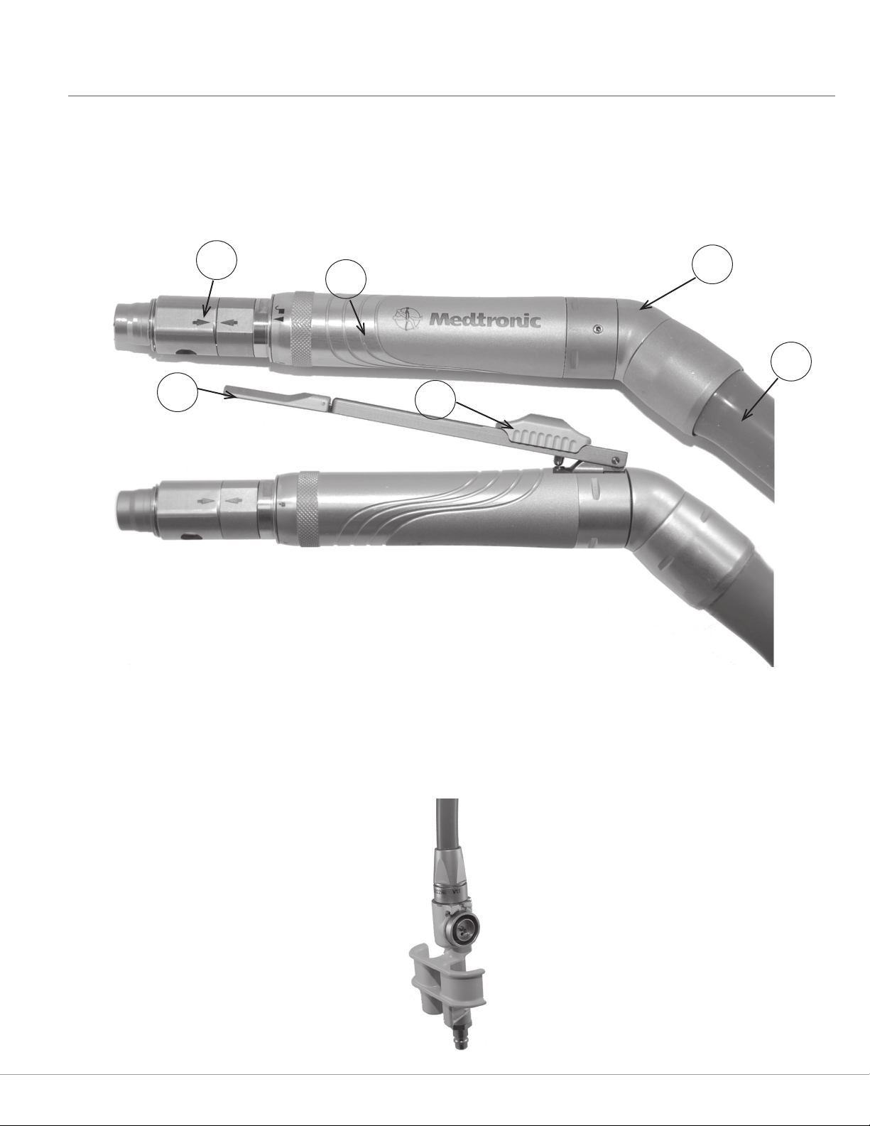
6. Safety Slide (MR7 Touch Only)
Non-Disposable Components
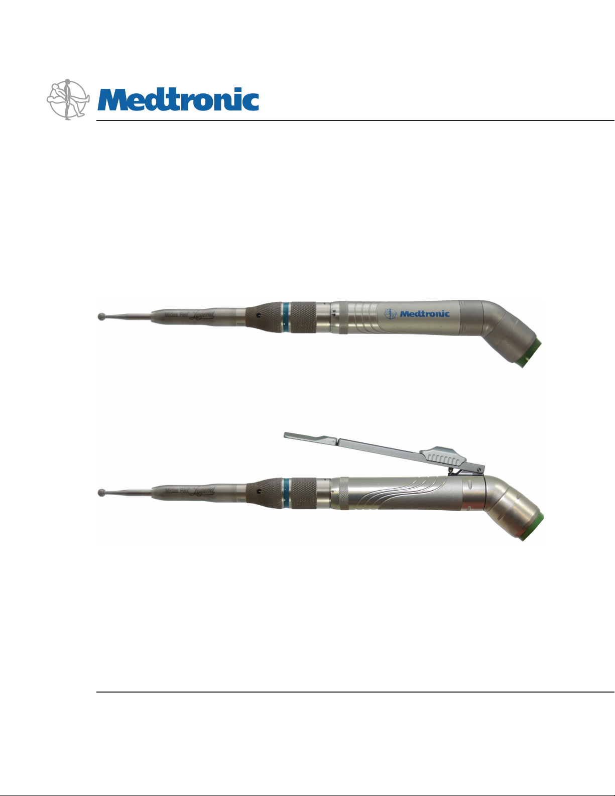
MR7 Motor
The MR7 motor is a high-speed, high-torque motor used to dissect bone and biomaterials.
Figure 1: Motor Components
System Components
1
5
1. Collet
2. Motor Case
3. Swivel
4. Hose
5. Finger Control Lever
3
2
4
6
In addition to the components listed in Figure 1, each MR7 motor has a lubricant/diuser housing at the end of the motor
hose, as seen in Figure 2.
Figure 2: Lubricant/Diuser Housing
3
Page 9
System Components
WARNING: Use only Medtronic Midas Rex Legend or MR7
devices with an MR7 motor. Use of other devices may
cause injury or damage equipment, and will void the
manufacturer’s warranty.
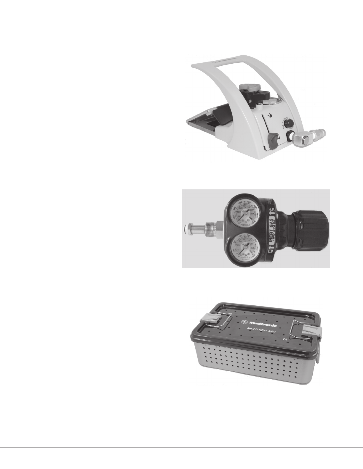
Pneumatic Control Unit
The pneumatic control unit (Figure 3) provides variable
speed motor control controls through a foot pedal. It also
allows the user to switch between nger and foot control
of the motor (if applicable).
Regulator
The regulator (Figure 4) controls the delivery pressure
of compressed gas to the pneumatic control unit. The
pressure gauges monitor cylinder pressure (right gauge)
and delivery pressure (left gauge).
Note: Outlet pressure gauge accurate to +/- 12 psi.
Figure 3: Pneumatic Control Unit
Instrument Case
The instrument case (Figure 5) is used to organize
equipment.
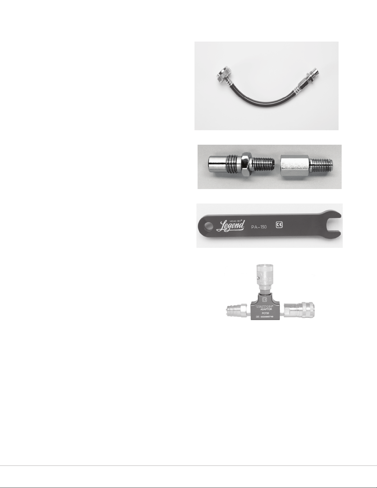
Regulator Hose
Connects from the gas source to the pneumatic control
unit to deliver compressed gas.
Figure 4: Regulator
Figure 5: Instrument Case
4
Page 10
System Components
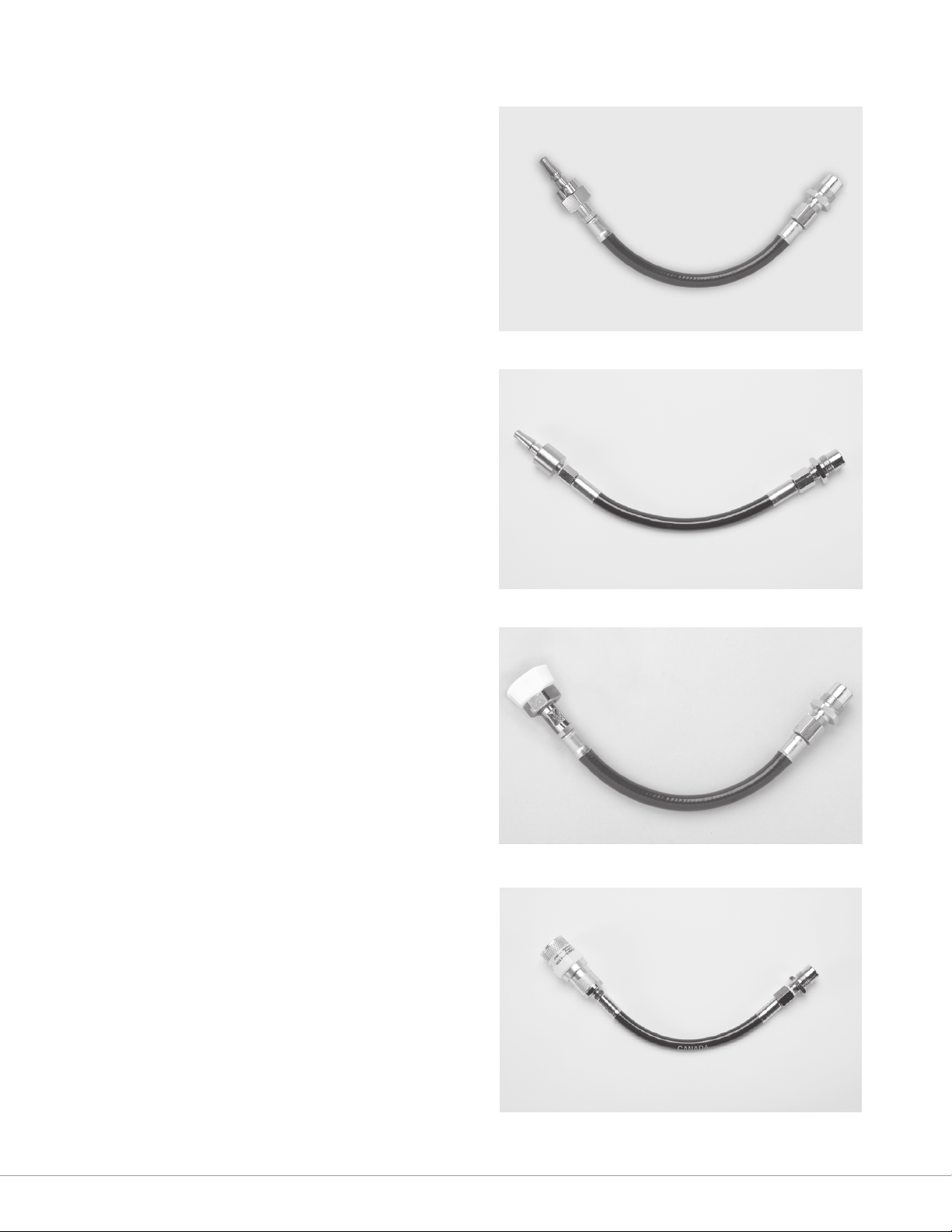
N2 DISS to Male Schrader Adapter
(PC110)
The N2 DISS to male Schrader adapter (Figure 6) allows
for the regulator hose to be attached to a female
Schrader in-house gas connection.
N2 DISS to Male Schrader Adapter
- UK (PC111)
The N2 DISS to male Schrader adapter (Figure 6a)
allows for the Pneumatic Control Unit’s N2 DISS
pressure hose connection to be attached to a Female
Schrader (UK) in-house gas connection.
N2 DISS to Air DISS Adapter
(PC120)
The N2 DISS to air DISS adapter (Figure 7) allows for
the regulator hose to be attached to an Air DISS inhouse gas connection.
N2 DISS to Female Schrader
Adapter (PC140)
The N2 DISS to female Schrader adapter (Figure
7a) allows for the Pneumatic Control Unit’s N2 DISS
pressure hose connection to be attached to a Male
Schrader in-house gas connection.
Figure 6. N2 DISS to Male Schrader Adapter
PC110
Figure 6a. N2 DISS to Male Schrader Adapter - UK
PC111
Figure 7. N2 DISS to Air DISS Adapter
PC120
Figure 7a. N2 DISS to Female Schrader Adapter
PC140
5
Page 11
System Components
N2 DISS to Surgical Tool Air Male SIS
Adapter (PC150)
The N2 DISS to surgical tool air male SIS adapter (Figure 7b)
allows for the Pneumatic Control Unit’s N2 DISS pressure
hose connection to be attached to an AUS-SIS surgical tool
air in-house gas connection.
N2 DISS to WF4 Adapter
The N2 DISS to WF4 adapter (Figure 8) allows for the
regulator hose to be attached to a Midas Rex safety valve
regulator previously used for Midas Rex Classic or Midas Rex
III motors. The in-line oiler must be removed from the safety
valve regulator.
Motor Wrench
The motor wrench (Figure 9) is used to align arrows
on motor collet ats prior to installation of a Legend
attachment.
Triton Adapter
The Triton adapter (Figure 10) allows the Triton handpiece
to be driven by the MR7 pneumatic control unit. It functions
much the same way as the Triton port on the Legend
pneumatic control unit, except that it is connected between
the control unit and the gas source, rather than being
integrated into the control unit
Figure 7b. N2 DISS to Surgical Tool Air Male SIS Adapter
PC150
Figure 8. N2 DISS to W4 Adapter
Figure 9. Motor Wrench
Figure 10. Triton Adapter
6
Page 12

System Components
Legend Attachments
Legend motor attachments are available in various designs to facilitate a variety of surgical procedures. Attachments vary in
length, diameter, and overall design. They are marked and color-coded to correspond with their associated dissecting tools.
A few of the Legend attachments available are listed in the table below.
Attachment Example Other Details/Options
Standard Straight Attachments AS09
Standard Angled Attachments AA14
Straight Variable Exposure Attachments AVS07
Angled Variable Exposure Attachments AVA07
Fixed Footed Attachments AF01
Rotating Footed Attachments AF01R
Telescoping Attachments AT10 (base)
TT12A (tube)
Contra-Angle Attachment AC16
Metal Cutting Attachment ASMC
Perforator Attachment AD01 Available in 800 RPM or 1000 RPM form.
5/32” Jacobs Chuck Attachment AD02
Bone Mill Attachment BM100
NOTE: Angled and straight attachments with the same length, marking, and color band share the same dissecting tool.
Curved and straight telescoping tubes with the same length, marking, and color band also share the same dissecting tool.
Example: The 14-AM straight and 14-AM angled attachments are 14 cm long, marked 14-AM and have a green color band.
All dissecting tools with the prex 14 (14MH30) may be used in either the 14-AM straight or 14-AM angled attachment.
The telescoping attachment requires the use of the AT10
attachment base, as well as a telescoping tube. Tubes are
available in straight, curved, or hooded form.
Be sure to match the color code and nomenclature on the Legend Dissecting Tool packaging with the color band and
nomenclature on the Legend Attachment.
7
Page 13
System Components
Disposable Components
WARNING: Use only Medtronic Midas Rex Legend or
MR7 devices with an MR7 motor. Use of other devices
may cause injury or damage equipment, and will void
the manufacturer’s warranty.
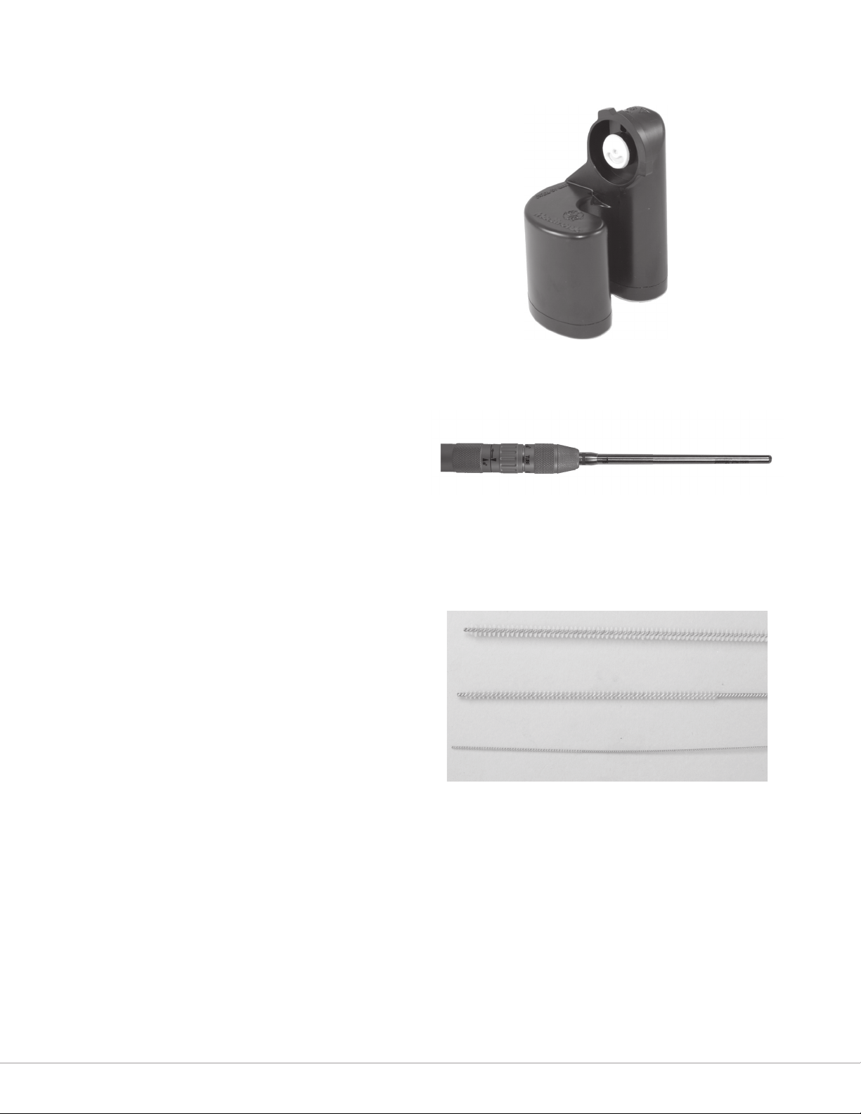
Lubricant/Diffuser Cartridge
The lubricant/diuser cartridge (Figure 11) provides
lubrication to the motor and lters oil from exhausted air.
Telescoping Tubes
Telescoping tubes (Figure 12) provide support to the
rotating dissecting tool. Telescoping tubes are disposable
following multiple uses and should be discarded when
heat or excessive vibration is noticed or insertion of tools
becomes dicult.
Cleaning Brushes
Cleaning brushes (Figure 13) are used to clean debris
from lumen of attachments and telescoping tubes. Sized
for an internal bore diameter of 3.2 mm, 2.4 mm or 1.2
mm in Legend Attachments and Telescoping Tubes.
NOTE: Cleaning brushes will not pass through angled,
contra-angle, metal cutting, perforator, or Jacobs Chuck
attachments, because they are not cannulated.
Figure 11: Lubricant/Diuser Cartridge
Figure 12: Telescoping Tube
Figure 13: Cleaning Brushes
3.2mm
2.4mm
1.2mm
8
Page 14

System Components
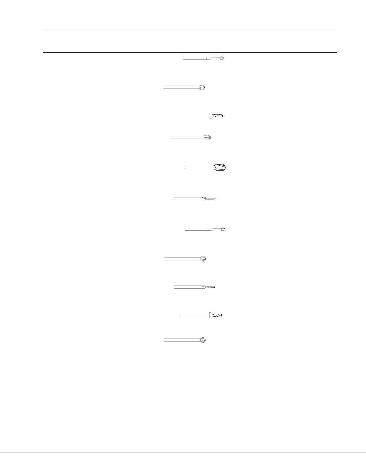
Legend® Dissecting Tools
Legend dissecting tools are sterile cutting tools, intended for cutting bone and biomaterials.
Dissecting Tool Nomenclature
Part numbers for Legend dissecting tools follow a standard naming convention, which is described in the diagram below.
A basic part number consists of the associated attachment length, the tool head shape, and the tool head diameter. Part
numbers may also include a variety of prexes to identify specic attachment types, as well as a variety of suxes to provide
additional information about the dissecting tool. Tools that use a design taken from the Mednext line are designated by an
additional “-MN” sux.
Associated
Attachment
Length
(x.x millimeters)
Tool
Head Diameter
Optional
Prex
Tool
Head Shape
Optional
Sufx
Tool Number Prexes (not all inclusive)
F... For use with footed attachments
MC For use with metal cutting attachments
T For use with telescoping attachments
Tool Head Shapes (not all inclusive)
AC Acorn MH Match Head
BA Ball OV Oval
CY Cylinder RT Reverse Taper
HM Hole Maker TA Tapered
HS Hole Saw TD Twist Drill
Tool Number Sufxes (note that more than one of the suxes listed may be combined in a single part number)
L Long S Spiral
D Diamond SH Short
X Extra DC Diamond Coarse
F Fine DX Diamond Extra Coarse
C Carbide MN Mednext Tool Design
9
Page 15

System Components
WARNINGS:
• Dissecting tools are for single-use only. Do not attempt to sterilize them. The dissecting tools are packed sterile and are
not intended for repeat use. To prevent contamination, use only once.
• Do not use an attachment and dissecting tool combination that results in tool ail or excessive vibration.
• Do not attempt to remove a tool while the motor is running.
• Do not attempt to remove a tool from an overheated motor or attachment.
• Do not use the device if the package is opened or damaged.
General Guidelines For Attachment and Tool Applications
These are general guidelines for dissecting tool applications and are not an all-inclusive listing.
WARNING: Be sure to match the color code and nomenclature on the Legend Dissecting Tool packaging with the color
band and nomenclature on the Legend Attachment. Failure to do so could result in injury to the patient or operating room
sta.
Surgical
Application
Spine 8-B, 9-M, 14-AM,
Commonly
Used
Attachments
15-A
Telescoping Match Head
Footed, Straight Tapered
Commonly Used
Dissecting Tools
Match Head
Elongated spherical design allows controlled, delicate
dissection. For entry hole, nerve decompression, osteophyte
removal, sinus dissection, etc.
Ball
Helical cutting utes dissect bone or cement eectively
from a wide variety of approach angles. For debridement,
decortication, sinus dissection, etc.
Oval
Helical cutting utes and curved design blend acorn and ball
styles to vary dissection eciency with approach angle. For
decortication, laminotomy, entry hole, nerve decompression,
osteophyte removal, etc.
Hole Maker/Saw
Matched sets of Hole Makers and Hole Saws are ecient and
eective for interbody fusion.
Cylinder
Eective bone sculpting and planing. For graft shaping,
debridement, corpectomy, decortication, interbody fusion,
fusion takedown, etc.
Acorn
Curved design varies dissection eciency with varied
approach angles. For entry hole, laminotomy, bone shaping,
debridement, corpectomy, decortication, fusion takedown, etc.
Elongated spherical design allows controlled, delicate
dissection. For entry hole, nerve decompression, osteophyte
removal, sinus dissection, etc.
Slender design for precise dissection with minimal bone loss.
For transection, osteotomy, graft harvesting, bone shaping,
entry hole, suture hole, midface advancement, etc.
Suggested
Motor(s)
MR7, MR7
Touch
MR7, MR7
Touch
10
Page 16
System Components
Surgical
Application
Neurosurgical–
Cranial
General
Surgery and
Plastic Surgery
(Craniofacial/
Maxillofacial/
Sternotomy)
Ear, Nose, and
Throat (Otology,
Neurootology)
Commonly
Used
Attachments
7-6ST, 8-B, 9-M,
10-9ST, 14-AM,
15-A
Telescoping Match Head
Footed Tapered
7-6ST, 8-B, 9-M,
10-9ST, 14-AM
7-6ST, 10-9ST Ball
Match Head
Elongated spherical design allows controlled, delicate
dissection. For entry hole, nerve decompression, osteophyte
removal, sinus dissection, etc.
Ball
Helical cutting utes dissect bone or cement eectively
from a wide variety of approach angles. For debridement,
decortication, sinus dissection, etc.
Twist Drill
Helical design with stop produces a hole with a precise depth.
Ideal for plating.
Acorn
Curved design varies dissection eciency with varied
approach angles. For entry hole, laminotomy, bone shaping,
debridement, corpectomy, decortication, fusion takedown, etc.
Elongated spherical design allows controlled, delicate
dissection. For entry hole, nerve decompression, osteophyte
removal, sinus dissection, etc.
Slender design for precise dissection with minimal bone loss.
For transection, osteotomy, graft harvesting, bone shaping,
entry hole, suture hole, midface advancement, etc.
Match Head
Elongated spherical design allows controlled, delicate
dissection. For entry hole, nerve decompression, osteophyte
removal, sinus dissection, etc.
Ball
Helical cutting utes dissect bone or cement eectively
from a wide variety of approach angles. For debridement,
decortication, sinus dissection, etc.
Tapered
Slender design for precise dissection with minimal bone loss.
For transection, osteotomy, graft harvesting, bone shaping,
entry hole, suture hole, midface advancement, etc.
Twist Drill
Helical design with stop produces a hole with a precise depth.
Ideal for plating.
Helical cutting utes dissect bone or cement eectively
from a wide variety of approach angles. For debridement,
decortication, sinus dissection, etc.
Commonly Used
Dissecting Tools
Suggested
Motor(s)
MR7
MR7, MR7
Touch
MR7
11
Page 17

System Components
Surgical
Application
Orthopaedics 8-B, 9-M,
Biometals/
Bioceramics/
Biomaterials
Commonly
Used
Attachments
14-AM, 21-TU,
26-R, Footed,
Telescoping
Footed Tapered
MC Metal Cutter
Commonly Used
Dissecting Tools
Ball
Helical cutting utes dissect bone or cement eectively
from a wide variety of approach angles. For debridement,
decortication, sinus dissection, etc.
Tapered
Slender design for precise dissection with minimal bone loss.
For transection, osteotomy, graft harvesting, bone shaping,
entry hole, suture hole, midface advancement, etc.
Acorn
Curved design varies dissection eciency with varied
approach angles. For entry hole, laminotomy, bone shaping,
debridement, corpectomy, decortication, fusion takedown, etc.
Cylinder
Eective bone sculpting and planing. For graft shaping,
debridement, corpectomy, decortication, interbody fusion,
fusion takedown, etc.
Slender design for precise dissection with minimal bone loss.
For transection, osteotomy, graft harvesting, bone shaping,
entry hole, suture hole, midface advancement, etc.
Cutting utes or diamond wheel design remove metals,
ceramics and other biomaterials eectively from a variety
of approach angles. For cutting rods, pins, plates, implants,
screws, etc.
Suggested
Motor(s)
MR7, MR7
Touch
MR7, MR7
Touch
12
Page 18
Setting up the Operating Room
1.
2.
3.
4.
5.
6.
7.
8.
9.
10.
Power Source Requirements
Setting up the Operating Room
Required Operating
(Dynamic) Pressure
Nominal Operating
(Dynamic) Pressure
Approximate Flow Rate
Required
Gas Type
80–120 psi 100 psi 12 cubic feet/min. Nitrogen or Dry-Filtered
5.5–8.3 bar 6.9 bar 340 liters/min.
Compressed Air
CAUTION: Do not run the motor at an operating pressure above or below the required operating pressure range. Operating
pressure below 80 psi (5.5 bar) may not provide proper lubrication to the motor. Operating pressure above 120 psi (8.3 bar)
may damage or reduce the life of the motor.
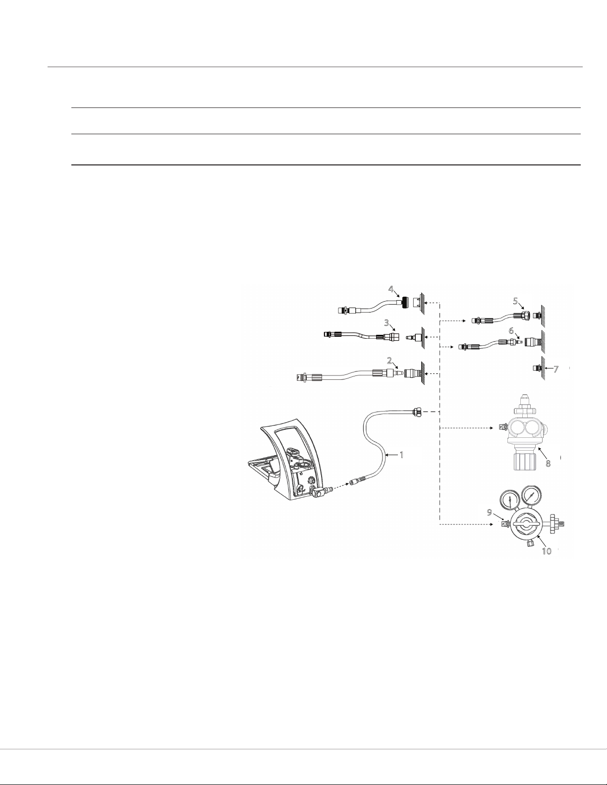
Pneumatic Connections
Figure 14: Gas Connection Options
4
5
Regulator Hose (N2 DISS)
N2 DISS to Male Schrader Adapter - UK Gas Source
N2 DISS to Female Schrader Adapter Gas Source
N2 DISS to Surgical Tool Air Male SIS Adapter Gas Source
N2 DISS to Air DISS Adapter Gas Source
N2 DISS to Male Schrader Adapter Gas Source
Gas Source (N2 DISS)
Regulator
DISS/WF4 Adapter
Regulator
3
6
2
7
1
8
9
10
WARNING: You must ensure the adapter is fully threaded onto the regulator hose and that the adapter is fully threaded/
connected to the corresponding wall outlet before operating the Pneumatic system.
CAUTION: If you are using the Midas Rex Safety Valve Regulator instead of the Legend Regulator, you must replace the
in-line oiler with the DISS/WF4 adapter before use.
13
Page 19
Setting up the MR7 System
Setting up the MR7 System
Installing the Oiler Cartridge
WARNING: Do not use the MR7 system with the Midas
Rex in-line oiler. The MR7 motor is suciently lubricated
by the lubricant/diuser on the motor hose, and will be
over-lubricated if the Midas Rex in-line oiler is used.
1. Set the non-running (static) pressure to 80–120 psi
(5.5–8.3 bar) at the gas source. Operating (dynamic)
pressure may be adjusted later.
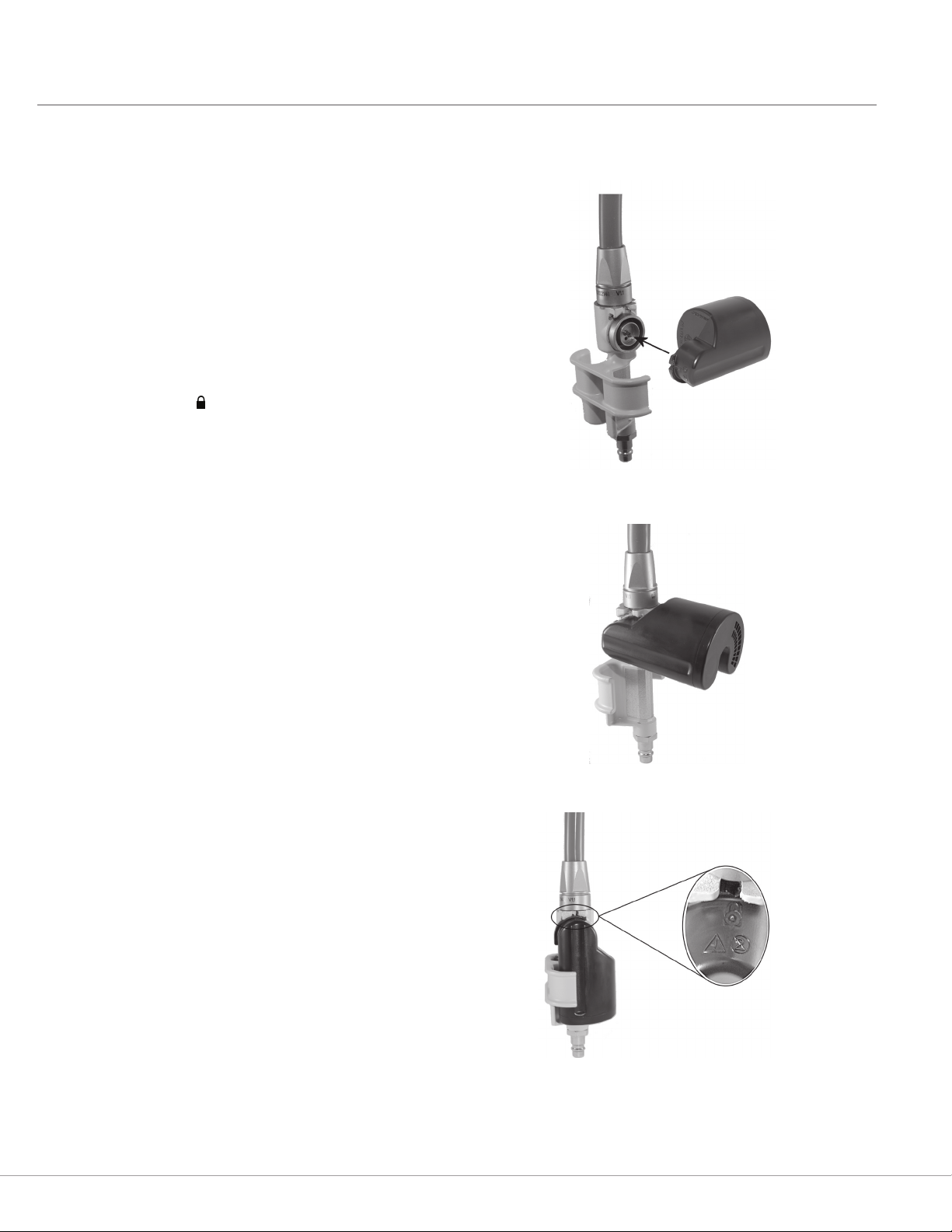
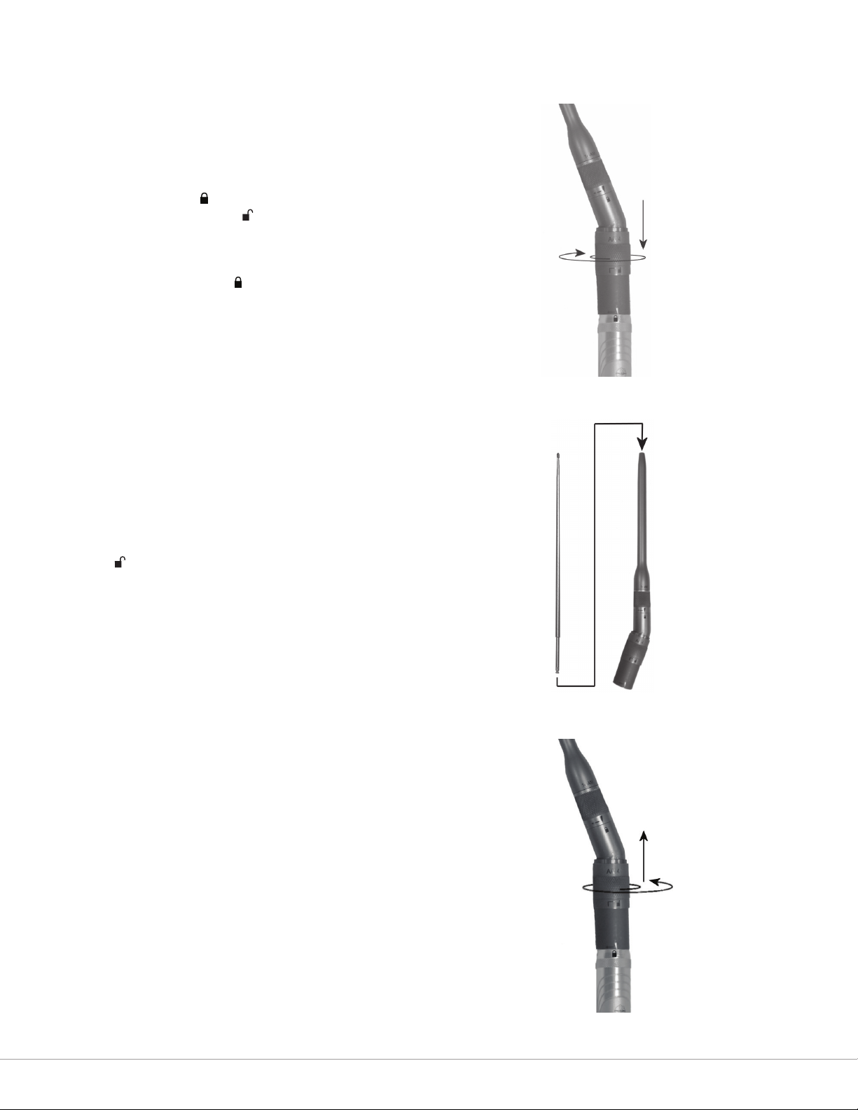
2. Hold the lubricant/diuser cartridge perpendicular
to the housing (Figure 15), and press the cartridge’s
circular tting onto the housing’s circular receptacle
(Figure 16), breaking the foil seal.
3. Rotate the cartridge down until it clicks into place.
4. Verify that the symbol on the cartridge is lined up
with the notch on the housing (Figure 17).
WARNINGS:
• Failure to properly secure the lubricant/diuser
cartridge may cause injury to operator and/or
operating room sta.
• Do not attempt to remove the lubricant/diuser
cartridge while the system is pressurized.
Figure 15: Aligning the Lubricant/Diuser Cartridge with the
Housing
Figure 16: Pressing the Cartridge onto the Housing
CAUTIONS:
• Do not use an MR7 motor without a lubricant/
diuser installed.
• Do not use a lubricant/diuser cartridge for more
than one hour of drill time.
• Do not re-use a lubricant/diuser cartridge. It is a
single-use product.
• Do not attempt to rell a used lubricant/diuser
cartridge.
• Do not use a lubricant/diuser cartridge if it appears
to be damaged, or if the inner foil seal is punctured.
Figure 17: Correctly Installed Lubricant/Diuser Cartridge
14
Page 20
Setting up the MR7 System
Connecting the Motor
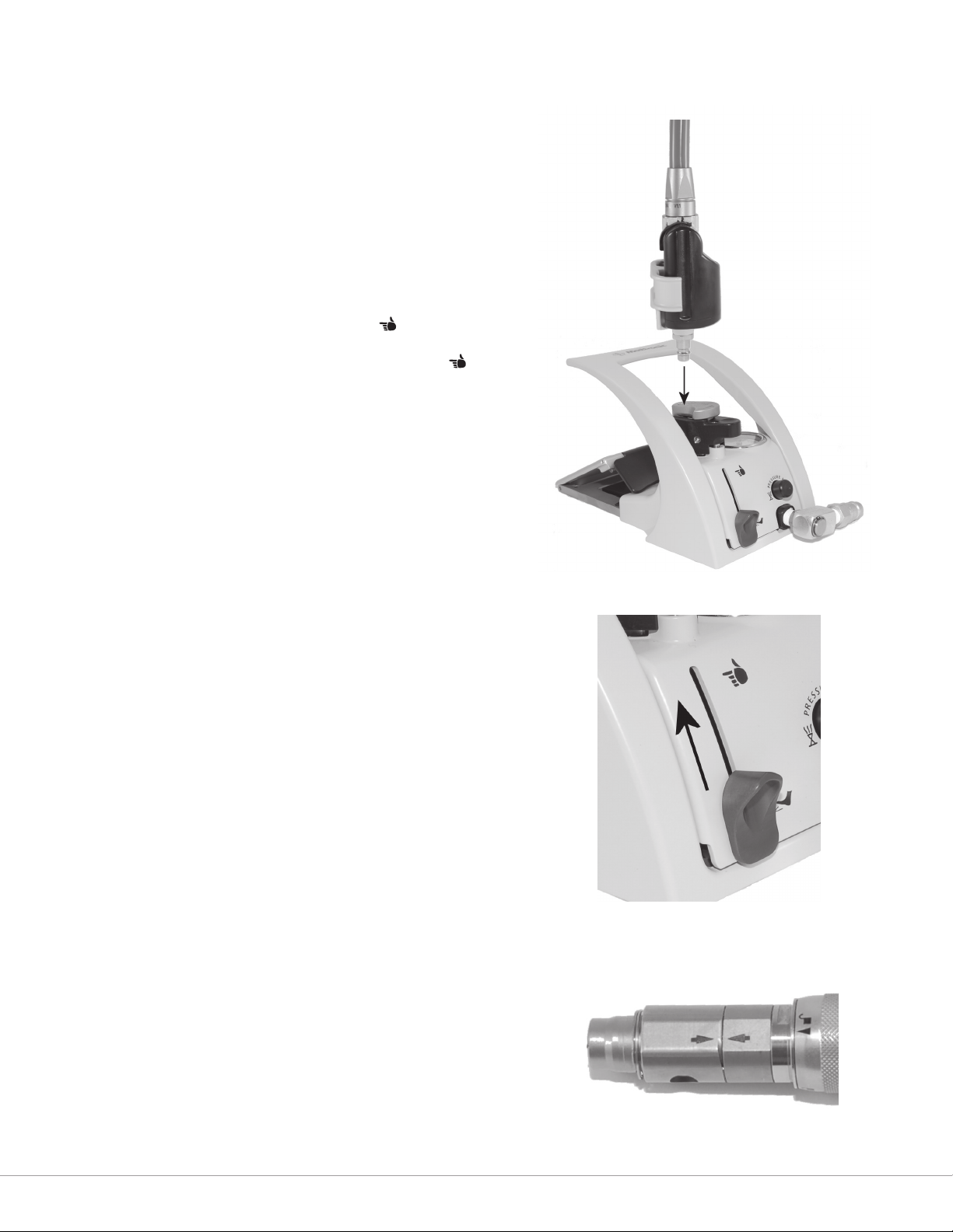
Connect the motor hose to the motor port on the top of
the pneumatic control unit, by swinging the port cover
to the side and pressing the end of the hose into the port
(Figure18).
WARNING: Do not pinch, kink, obstruct, cut, tear, or step
on the motor/exhaust hose. This may cause the hose to
burst, potentially injuring the patient or user.
NOTES:
• If using the MR7 Touch motor, slide the control slide
on the pneumatic control unit to the position
(Figure 19). This will automatically depress and lock
the foot pedal. The control will not lock into the
position unless the motor hose is connected into the
motor port. When the motor hose is removed from
the motor port, the foot pedal will return to normal
position.
• If using the Triton Power Surgical Instrumentation
System in conjunction with the MR7 motor, use the
optional Triton adapter to connect the Triton hose.
Refer to the documentation accompanying the
adapter for connection instructions.
Figure 18: Connecting the Motor Hose to the Motor Port
• The motor’s exhaust hose may have an oily lm
on the external surface from pressure and/or
temperature dierentials following sterilization.
Wipe the exhaust hose with a sterile cloth prior to
use. If motor continues to have oil on the exhaust
hose, return the motor to MPSS for refurbishing.
WARNING: To avoid injury to the patient or user, do not
use the pneumatic control unit to operate systems other
than the MR7, Legend, and Triton systems.
Prior to installation of a Legend attachment and
dissecting tool, ensure that the arrows on the motor
collet ats are aligned (Figure 20). If the arrows are not
aligned, use the motor wrench to turn the collet at
closest to the motor case until its arrow is aligned with
the arrow on the other collet at.
WARNING: To avoid injury when using the MR7 Touch
motor, ensure the safety slide is in the “O” position before
installing the attachment and tool.
Figure 19: Finger/Foot Control Slide
Figure 20: Aligning the collet ats
15
Page 21

Installing an Attachment and Tool
Installing an Attachment and Tool
WARNING: Dissecting tool utes are sharp and may
perforate surgical gloves. Tools may be grasped with a
hemostat to aid in installation and removal.
Straight Attachments
Installation:
1. Slide the attachment over the motor collet, aligning
the triangular markers (Figure 21). You will feel and
hear the attachment click into place when it is fully
seated.
2. Insert the dissecting tool into the attachment with a
slight rotational motion (Figure 22). You will feel and
hear the tool click into place when it is fully seated in
the attachment.
3. Turn the attachment to the position on the motor
case (Figure 23). Gently pull on the shaft of the
dissecting tool to verify proper installation.
Removal:
Removal is the reverse of installation.
Figure 21: Sliding the Attachment over the Motor Collet
Figure 22: Inserting the Dissecting Tool into the Attachment
Specialized Attachments
See Appendix A—Specialized Attachments for installation
and removal instructions for other attachments.
Figure 23: Attachment in the Locked Position
16
Page 22
Activating the Motor
Finger Control Lever
NOTE: In order to activate the MR7 Touch motor, the safety slide on the nger control switch must be in the | position, and
the control slide on the foot control must be in the position. The control slide will not lock in the position unless a
motor is connected to the motor port.
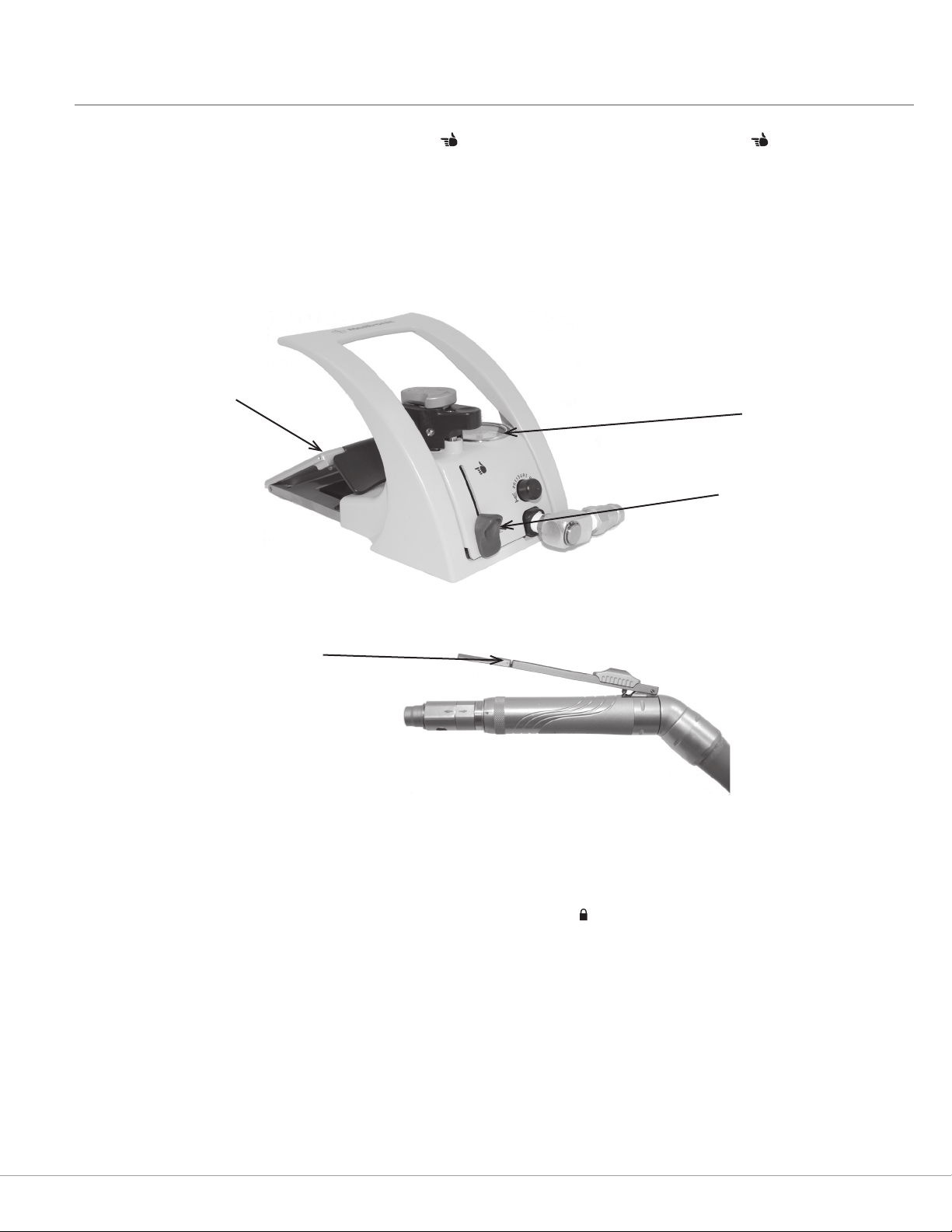
1. Activate the motor by pressing on the foot control pedal (Figure 24), or by pressing on the nger control lever (MR7
Touch motor only).
2. Adjust operating pressure as needed at the compressed gas source until supply pressure gauge on pneumatic control
unit reads within a range of 80–120 psi (5.5–8.3 bar) as required. Operating pressure (with motor running) will decrease
slightly from the non-running (static) pressure setting when the motor is activated.
Figure 24: Foot Control Pedal
Foot Control Pedal
Air Pressure Gauge
Activating the Motor
Control Slide
Figure 25: MR7 Finger Control Switch
WARNINGS:
• Do not use excessive force to pry or push bone with the attachment or tool during dissection. This could cause the tool
to break and cause injury to the patient or operating room sta.
• Use adequate irrigation during dissection, to prevent thermal necrosis.
• MR7 motors should only be operated when the attachment is in the position.
NOTE: To decrease pressure, turn down the in-house compressed gas source or loosen the pressure handle on the
regulator. Push down on the pressure relief at the pneumatic control unit to exhaust excess pressure in the hoses. Then
re-adjust pressure as needed.
17
Page 23

Disassembling the MR7 System
Disassembling the MR7 System
Depressurize the System
1. Turn o the compressed gas at the source.
2. Press the pressure relief button on the pneumatic control unit, to release remaining gas.
WARNING: Do not disassemble equipment including adapter hose(s), before the gas is released from control unit.
Disconnect Hoses
Release the motor hose from the control unit, by holding the hose rmly and pressing the motor port connection button.
Figure 26: Motor Port Connection and Pressure Relief Buttons
Motor Port Connection Button
Pressure Relief Button
Discard the Lubricant/Diffuser Cartridge
Remove the lubricant/diuser cartridge from the housing and discard it.
CAUTION: Do not re-use a lubricant/diuser cartridge. It is a single-use product.
Remove the Attachment and Tool
1. Follow the applicable removal instructions in the Installing an Attachment and Tool section of this manual to remove the
attachment and tool from the motor.
WARNING: Dissecting tool utes are sharp and may perforate surgical gloves. Tools may be grasped with a hemostat to aid
in installation and removal.
2. Discard used dissecting tools in an appropriate container.
18
Page 24

Cleaning & Sterilizing the MR7 System
MR7 Motor
Cleaning & Sterilizing the MR7 System
Warnings and
Precautions
Limitations Verify functionality prior to re-use.
INSTRUCTIONS
Point of Use No particular requirements. Follow hospital procedures.
Containment and
Transportation
Preparation for
Decontamination
Cleaning:
Automated
(Do NOT use ultrasonic
washer)
Cleaning: Manual Wipe all external surfaces of the motor and hose, and wipe inner surface of oiler housing with a cloth dampened with a neutral
Disinfection No particular requirements. Follow hospital procedures.
Packaging For sterilization, place devices in instrument tray. Devices may be unwrapped, or wrapped with up to two layers of 1-ply
Sterilization
(Temperatures are
minimum required,
times are minimum
required)
Do not soak/submerge MR7 devices.
Do not use ultrasound to clean MR7 devices.
Do not use chlorine based or corrosive cleaning agents such as bleach, lye, acetone, sodium hypochlorite/bleach, sodium
hydroxide, formic acid, or solutions containing glutaraldehyde.
The use of a washer-disinfector for cleaning may cause a pre-mature degradation in performance.
Allow an adequate cooling period after steam sterilization.
Use ONLY nylon cleaning brushes. Non-nylon cleaning brushes leave residue that may prevent the tool from being secured
properly in the handpiece.
It is recommended that devices are reprocessed as soon as is practical following use.
No particular requirements. Follow hospital procedures.
Review the washer-disinfector warning above, before using this cleaning method. Remove devices from instrument trays
before placing into washer baskets. Orient devices following recommendations of the washer/disinfector manufacturers. Verify
that devices are visually clean after automated cleaning.
Recommended Washer Cycle
Pre-Wash: Cold tap water, 2 min.
Wash: 66oC, 5 min. using a neutral enzymatic detergent, pH 6.0–8.0
Rinse: Hot tap water, 1 min.
enzymatic detergent, pH 6.0–8.0.
Brush motor case and collet with a nylon brush dampened with a neutral enzymatic detergent. If using the MR7 Touch motor,
be sure to brush under the nger control lever.
Rinse motor thoroughly under running water, collet end pointed down. Dry collet and motor with lint free towel.
Verify that devices are visually clean after manual cleaning.
polypropylene wrap
Steam Sterilization:
Cycle:
Temperature:
Time:
Drying:
Gravity
132°C
25 min.
15 minutes
Pre-vac
132°C
4 min.
15 minutes
Pre-vac (FR/WHO)
134°C
18 min.
20 minutes
Pre-vac (UK)
134°C
3 min.
10 minutes
Medtronic recommends incineration of devices that have directly or indirectly contacted patients suspected or
conrmed with prions or a Transmissible Spongiform Encephalopathy (TSE) such as Creutzfeldt-Jacob disease
(CJD).
STERRAD Sterilization: Do not use low temperature hydrogen peroxide gas plasma sterilization due to lumen internal diameter
and length restrictions.
100% EtO Sterilization Parameters:
Preconditioning: 51–59°C, 70 ±5% relative humidity, 30 min.
Temperature: 51–59°C
Relative humidity: 70 ±5%
Ethylene oxide concentration: 725 ± 25mg/L
Gas exposure time (full-cycle): 4 hours
Aeration: 18 hours at 51–59°C
Steris: Do not use liquid peracetic acid sterilization due to immersion procedure.
19
Page 25

Cleaning & Sterilizing the MR7 System
Maintenance,
Inspection and Testing
Storage Store with other sterile devices.
Inspect devices for any damage before and after each use. If damage is observed, do not use the device until it is repaired.
After cleaning and sterilization, verify functionality prior to re-use.
NOTE: The instructions provided above have been validated by the manufacturer as being CAPABLE of preparing the
product for re-use. It remains the responsibility of the processor to ensure that the reprocessing as actually performed,
using equipment, materials and personnel in the reprocessing facility, achieves the desired result. This normally requires
validation and routine monitoring of the process.
Legend Attachments / Tubes
Warnings and
Precautions
Limitations Verify functionality prior to re-use.
INSTRUCTIONS
Point of Use No particular requirements.
Containment and
Transportation
Preparation for
Decontamination
Cleaning:
Automated
(Do NOT use ultrasonic
washer)
Cleaning: Manual Wipe all attachments and telescoping tubes with a cloth, dampened with a surgical instrument cleaning solution.
Disinfection No particular requirements Follow hospital procedures.
Packaging For sterilization, place devices in instrument tray. Devices may be unwrapped, or wrapped with up to two layers of 1-ply
Do not soak/submerge Legend devices.
Do not use ultrasound to clean Legend devices.
Do not use chlorine based or corrosive cleaning agents such as bleach, lye, acetone, sodium hypochlorite/bleach, sodium
hydroxide, formic acid, or solutions containing glutaraldehyde.
The use of a washer-disinfector for cleaning may cause a pre-mature degradation in performance.
Allow an adequate cooling period after steam sterilization.
Use ONLY nylon cleaning brushes. Non-nylon cleaning brushes leave residue that may prevent the tool from being secured
properly in the handpiece.
It is recommended that devices are reprocessed as soon as is practical following use.
No particular requirements. Follow hospital procedures.
Review the washer-disinfector warning above, before using this cleaning method. Manually rinse attachments/
tubes under tap water, until no visible soil is noticed, before placing them into the automatic washer.
Devices with moving parts should be actuated through their full range of motion under running water. Remove
devices from instrument trays before placing into washer baskets. The variable exposure attachment should be
placed in the basket with the tube in the fully extended position. Orient devices following recommendations of
the washer/disinfector manufacturers.
Recommended Washer Cycle
Pre-Wash: Cold tap water, 2 min.
Wash: 66°C, 5 min. using a neutral enzymatic detergent, pH 6.0–8.0
Rinse: Hot tap water, 1 min.
Immerse the head of Contra-Angle attachments in surgical instrument cleaning solution and run the motor for 1 minute.
Other attachments and tubes may be mechanically agitated in cleaning solution, but not soaked or immersed.
A nylon brush dampened with a surgical instrument cleaning solution may be used to clean the external surfaces and internal
connecting surfaces of the attachments and tubes.
Straight attachments, footed attachments and telescoping straight tubes have special cleaning brushes sized to the
attachment’s or telescoping tube’s internal diameter. Push the brush wet with surgical instrument cleaning solution through
the attachment or telescoping tube from rear to front to loosen and remove debris trapped inside.
Move any moveable parts back and forth to allow solution to thoroughly clean attachment, e.g., sleeve on footed attachment,
perforator attachment.
Rinse thoroughly with tap water.
Thoroughly dry attachments. An air gun may be used to blow moisture out from rear to front of attachment.
Using an aerosol spray lubricant (such as Pana Spray), perform the following steps to lubricate attachments:
Holding the can approximately 10–15 cm (3–6 in.) away from the attachment, spray all components that move, rotate, or
slide with three quick squirts.
Articulate movable components to ensure proper lubrication.
Remove excess lubricant with a clean cloth.
polypropylene wrap.
20
Page 26

Cleaning & Sterilizing the MR7 System
Sterilization
(Temperatures are
minimum required,
times are minimum
required)
Steam Sterilization:
Cycle:
Temperature:
Time:
Drying:
Gravity
132°C
25 min.
15 minutes
Pre-vac
132°C
4 min.
15 minutes
Pre-vac (FR/WHO)*
134°C
18 min.
20 minutes
Pre-vac (UK)*
134°C
3 min.
10 minutes
Medtronic recommends incineration of devices that have directly or indirectly contacted patients suspected or
conrmed with prions or a Transmissible Spongiform Encephalopathy (TSE) such as Creutzfeldt-Jacob disease
(CJD).
STERRAD Sterilization: Do not use low temperature hydrogen peroxide gas plasma sterilization due to lumen internal diameter
and length restrictions.
100% EtO Sterilization Parameters:
Preconditioning: 51–59°C, 70 ±5% relative humidity, 30 min.
Temperature: 51–59°C
Relative Humidity: 70 ±5%
Ethylene oxide concentration: 725 ± 25mg/L
Gas exposure time (full-cycle): 4 hours
Aeration: 18 hours at 51–59°C
Steris: Do not use liquid peracetic acid sterilization due to immersion procedure.
Maintenance,
Inspection and Testing
Storage Store with other sterile devices.
Inspect devices for any damage before and after each use. If damage is observed, do not use the device until it is repaired.
Verify functionality prior to re-use.
NOTE: The instructions provided above have been validated by the manufacturer as being CAPABLE of preparing the
product for re-use. It remains the responsibility of the processor to ensure that the reprocessing as actually performed,
using equipment, materials and personnel in the reprocessing facility, achieves the desired result. This normally requires
validation and routine monitoring of the process.
21
Page 27

Cleaning & Sterilizing the MR7 System
MR7 Pneumatic Control Unit / Regulator Hose / Triton Adapter /
Instrument Case
Warnings and
Precautions
Limitations Verify functionality prior to re-use.
INSTRUCTIONS
Point of Use No particular requirements. Follow hospital procedures.
Containment and
Transportation
Preparation for
Decontamination
Cleaning:
Automated
(Do NOT use ultrasonic
washer)
Cleaning: Manual Wipe the pneumatic control unit, regulator hose, Triton adapter, and instrument case with a cloth dampened with surgical
Disinfection No particular requirements. Follow hospital procedures.
Packaging No particular requirements. Follow hospital procedures.
Sterilization Do not sterilize pneumatic control unit, regulator hose, adapter hose, or Triton adapter.
Maintenance,
Inspection and Testing
Storage Do not store with sterile devices.
Do not soak/submerge MR7 devices.
Do not use ultrasound to clean MR7 devices.
Do not use chlorine based or corrosive cleaning agents such as bleach, lye, acetone, sodium hypochlorite/bleach, sodium
hydroxide, formic acid, or solutions containing glutaraldehyde.
Do not sterilize the MR7 pneumatic control unit, regulator hose, adapter hose, or Triton adapter.
It is recommended that devices are reprocessed as soon as is practical following use.
No particular requirements. Follow hospital procedures.
Not validated.
instrument cleaning solution after each use.
Inspect devices for any damage before and after each use. If damage is observed, do not use the device until it is repaired.
Verify functionality prior to re-use.
NOTE: The instructions provided above have been validated by the manufacturer as being CAPABLE of preparing the
product for re-use. It remains the responsibility of the processor to ensure that the reprocessing as actually performed,
using equipment, materials and personnel in the reprocessing facility, achieves the desired result. This normally requires
validation and routine monitoring of the process.
Transmissible Spongiform Encephalopathies (TSE) Return Policy
Reusable devices that have been used on patients with suspected Creutzfeldt-Jakob Disease (CJD) or other Transmissible
Spongiform Encephalopathies (TSE) should be quarantined and not reused until a diagnosis is conrmed or excluded.
Medtronic Powered Surgical Solutions (MPSS) will not authorize or accept the return of MPSS products that directly
contacted a patient or are contaminated with a patient’s body uids that is suspected or conrmed with TSE or CJD
diagnosis. Furthermore, MPSS recommends that all MPSS product used on a patient conrmed with or suspected of a TSE/
CJD diagnosis be incinerated. If TSE/CJD is excluded as a diagnosis, the quarantined reusuable equipment may be returned
for use after appropriate cleaning, decontamination and sterilization. Hospital personnel should contact their infection
control personnel for current procedures and policy for reusable equipment processing.
Contact your Sales Representative for temporary equipment while original equipment is quarantined or for replacement of
product incinerated under this policy. Contact MPSS Regulatory Aairs Department for additional information regarding
TSE/CJD contamination.
22
Page 28

Troubleshooting
NOTE: All Legend and MR7 devices returned for servicing or refurbishing should be properly cleaned and sterilized prior to
shipping.
Motor not Running or Low on Power:
Possible Cause Solution
Hoses not properly connected. Make sure all connections are secure.
Operating pressure inadequate. Check gas supply pressure gauge. Increase pressure
according to compressed gas requirements, if necessary.
Attachment not properly installed and locked onto the motor. Remove and re-install attachment and tool to ensure
proper installation and locking of attachment onto
motor.
Foot pedal on pneumatic control unit not functioning
properly.
Motor stalls. Manually spin the dissecting tool, then activate the
Check for obstructions under the foot pedal. If foot pedal
continues to fail, return the pneumatic control unit to
MPSS to be refurbished.
motor. If the motor continues to stall, return it to MPSS to
be refurbished.
Troubleshooting
Motor Continues to Run:
Possible Cause Solution
Pneumatic control unit is not functioning properly. Depressurize the system and return the pneumatic
control unit to MPSS to be refurbished.
Finger control is not functioning properly. Return motor to MPSS to be refurbished.
Pneumatic control unit is locked in the nger control position. Move the nger control lever to the foot control position.
System Makes an Abnormal Noise:
Possible Cause Solution
Inadequate lubrication. Check for proper installation of the lubricant/diuser
cartridge. If the problem persists, replace the cartridge.
If replacing the cartridge doesn’t x the problem, return
the motor to MPSS for refurbishing.
Motor’s exhaust hose is damaged, or internal pressure hose is
detached.
Worn bearings. Switch attachments to determine whether the bearings
Attachment not properly installed and locked onto the motor. Remove and reinstall attachment and tool to ensure
Safety relief valve has been activated by high air pressure. Ensure that air operating/dynamic air pressure is no
Depressurize the system and return the motor to MPSS
to be refurbished.
are failing in the motor or in the attachment. Return the
failing component to MPSS to be refurbished.
proper installation and locking of the attachment onto
the motor.
higher than 120 psi.
23
Page 29

Troubleshooting
Motor is Too Hot to Touch/Hold:
Possible Cause Solution
Inadequate cool down period following sterilization. Motor must be allowed to cool down following steam
Inadequate lubrication. Check for proper installation of the lubricant/diuser
Attachment transferring heat to the motor. Switch attachments to determine whether the heat is
Heavy side loading during dissection. Discontinue use and rest the motor by using it
Inadequate irrigation. Ensure adequate irrigation to surgical site during bone
Attachment Will not Properly Seat on the Motor:
Possible Cause Solution
Motor collet ats are not aligned. Use the Legend motor wrench to rotate the at closest to
sterilization.
cartridge.
being generated by the motor or the attachment. Return
the failing component to MPSS for refurbishing.
intermittently or wrap the motor with a moist sterile
towel. If overheating continues, return the motor to
MPSS for refurbishing.
dissection.
the motor case until its marker is aligned with the marker
on the at farthest away from the motor case.
Tool is Difcult to Remove from Attachment:
Possible Cause Solution
Aging of attachment. Return to MPSS to be refurbished, or purchase new
Improper cleaning.
Use of reprocessed tools.
Use of an unauthorized refurbisher.
equipment.
16-MF Contra-Angle Attachment is Overheating:
Possible Cause Solution
The Contra-Angle attachment operates by a set of internal
gears to engage the drive shaft. It is normal for some heat to
be generated approximately 2cm from the distal end of the
attachment and at the right of the angle head.
Verify pressure setting of 80 psi (5.5 bar).
If heat continues or is excessive, return the attachment to
MPSS to be refurbished or purchase new equipment.
Perforator is Running too Slow:
Possible Cause Solution
Pressure set incorrectly. Check the pressure setting at the foot control.
24
Page 30

Troubleshooting
Dissecting Tool Flails:
Possible Cause Solution
A non-Legend dissecting tool is being used. Replace with a Legend dissecting tool.
Worn attachment or tube bearings. Try another attachment or tube to isolate the location
of the problem. If the attachment is failing, return it to
MPSS. If the tube is failing, dispose of it and use a new
tube.
Attachment/tube and tool are not compatible. Match color code on the dissecting tool packaging to the
color code on the attachment/tube.
Motor is damaged. Return motor to MPSS to be refurbished.
Dissecting tool’s size and geometry may contribute to ailing
at certain speeds.
Adjust the speed by changing the pressure setting or
foot/nger control. Do not use if ailing persists. Change
dissecting tools.
Dissecting Tool Vibrates Excessively:
Possible Cause Solution
Dissecting tool’s size and geometry may create excessive
vibration at certain speeds.
Adjust the speed by changing the pressure setting or
foot/nger control. Change dissecting tools.
Dissecting Tool Will not Seat Properly in the Motor or Attachment Collet:
Possible Cause Solution
Debris in collet of attachment or motor. Clean the attachment or motor thoroughly according
to the instructions in this manual. If cleaning does not
correct the problem, return the attachment or motor to
MPSS to be refurbished.
A non-Legend dissecting tool is being used. Replace with a Legend dissecting tool.
Smoke is Generated by the Attachment or Motor:
Possible Cause Solution
Attachment is not in the locked position. Make sure the attachment is in the locked position.
25
Page 31

Refurbishing or Repairs
Refurbishing or Repairs
When the MR7 System requires servicing or refurbishing, contact Medtronic Powered Surgical Solutions Repair Services for
a return authorization and instructions for returning the equipment. Medtronic Powered Surgical Solutions provides quality
assured service by factory-trained personnel who will utilize genuine Midas Rex Legend parts as required. All items being
returned for servicing or refurbishing should be properly cleaned and sterilized prior to shipping.
Contact:
Medtronic Powered Surgical Solutions Repair Services:
(800) 335-9557 or (817) 788-6440
mmrcustomerservice@medtronic.com
Peak performance, reliability and maximum service life from your MR7 System may be assured by using only those Midas
Rex Legend products for your MR7 System that are manufactured by and sold through Medtronic Powered Surgical
Solutions, Fort Worth, Texas. While Medtronic Powered Surgical Solutions guarantees complete compatibility among its
products within a specic product line, the dissecting tools are designed for single-use only, and Medtronic disclaims any
responsibility when reprocessed dissecting tools are used. If you would like more information about the patient and product
risks associated with reprocessed tools, please contact the number or e-mail address listed above.
Due to safety and environmental concerns, Medtronic Powered Surgical Solutions requests the return of pneumatic high
speed motors for proper disposal at the end of the product life cycles.
26
Page 32

Preventative Maintenance
Preventative Maintenance
The Midas Rex MR7 System Preventive Maintenance Manual has been developed to assist you in getting the greatest
ownership value from your MR7 System, while helping to maximize its performance, safety and reliability. The scheduled
preventive maintenance/service program is in addition to the required routine cleaning after each use. Please refer to the
preventive maintenance manual for the specic steps necessary to maintain the MR7 System.
27
Page 33

Limited Warranty
Limited Warranty
A. This Limited Warranty provides the following assurance to the purchaser of a Medtronic Midas Rex® MR7 Pneumatic
High Speed System. This Limited Warranty is extended only to the buyer purchasing the MR7 System directly from
Medtronic or from its aliate or its authorized distributor or representative. The Midas Rex® MR7 Pneumatic High
Speed System includes the motor, foot control, instrumentation cases and trays (hereafter referred to as System
Components), straight and angled motor attachments (hereinafter referred to as “Attachments”), telescoping tubes
(hereinafter referred to as Semi-reusable Components) and dissecting tools and other accessories not listed above
and jointly referred to as MR7 Pneumatic High Speed System, unless specically noted.
(1) Should a System Component fail to function to Medtronic’s published specications during the term of
this Limited Warranty (one year from the date of sale of a new System Component or 90 days from the
date of sale of a refurbished or used System Component), Medtronic will either repair or replace the Motor
Component or any portion thereof.
(2) Should an Attachment fail to function to Medtronic’s published specications during the term of this
Limited Warranty (90 days from the date of sale of a new Attachment), Medtronic will either repair or
replace the Attachment or any portion thereof.
(3) Should a Semi-reusable Component fail to function to Medtronic’s published specications during
the term of this Limited Warranty (30 days from the date of sale of a new Semi-reusable Component),
Medtronic will replace the Semi-reusable Component or any portion thereof.
(4) Should a Single Use Component fail to function to Medtronic’s published specications prior to its “use
by” date Medtronic will replace the Single Use Component.
B. To qualify for this Limited Warranty, these conditions must be met:
(1) The Product must be used on or before its “Use By” or “Use Before” date, if applicable.
(2) The Product must be used in accordance with its labeling and may not be altered or subjected to misuse,
abuse, accident or improper handling.
(3) Medtronic must be notied in writing within thirty (30) days following discovery of a defect.
(4) The Product must be returned to Medtronic within thirty (30) days of Medtronic receiving notice as
provided for in (3) above.
(5) Upon examination of the Product by Medtronic, Medtronic shall have determined that: (i) the Product was
not repaired or altered by anyone other than Medtronic or its authorized representative, (ii) the Product
was not operated under conditions other than normal use, and (iii) the prescribed periodic maintenance
and services, if applicable, have been performed on the Product
C. This Limited Warranty is limited to its express terms. THIS LIMITED WARRANTY IS IN LIEU OF ALL OTHER
WARRANTIES, EXPRESSED OR IMPLIED WHETHER STATUTORY OR OTHERWISE, INCLUDING ANY IMPLIED WARRANTY
OF MERCHANTABILITY OR FITNESS FOR A PARTICULAR PURPOSE. In no event shall Medtronic be liable for any
consequential, incidental, prospective or other similar damage resulting from a defect, failure, or malfunction of the
MR7 System, whether a claim for such damage is based upon the warranty, contract, negligence or otherwise.
D. The exclusions and limitations set out above are not intended to, and should not be construed so as to, contravene
mandatory provisions of applicable law. Users may benet from statutory warranty rights under legislation
governing the sale of consumer goods. If any part or term of this Limited Warranty is held by any court of
competent jurisdiction to be illegal, unenforceable, or in conict with applicable law, the validity of the remaining
portion of the Limited Warranty shall not be aected, and all rights and obligations shall be construed and enforced
as if this Limited Warranty did not contain the particular part or term held to be invalid.
28
Page 34
Appendix A—Specialized Attachments
Appendix A—Specialized Attachments
Angled Attachments
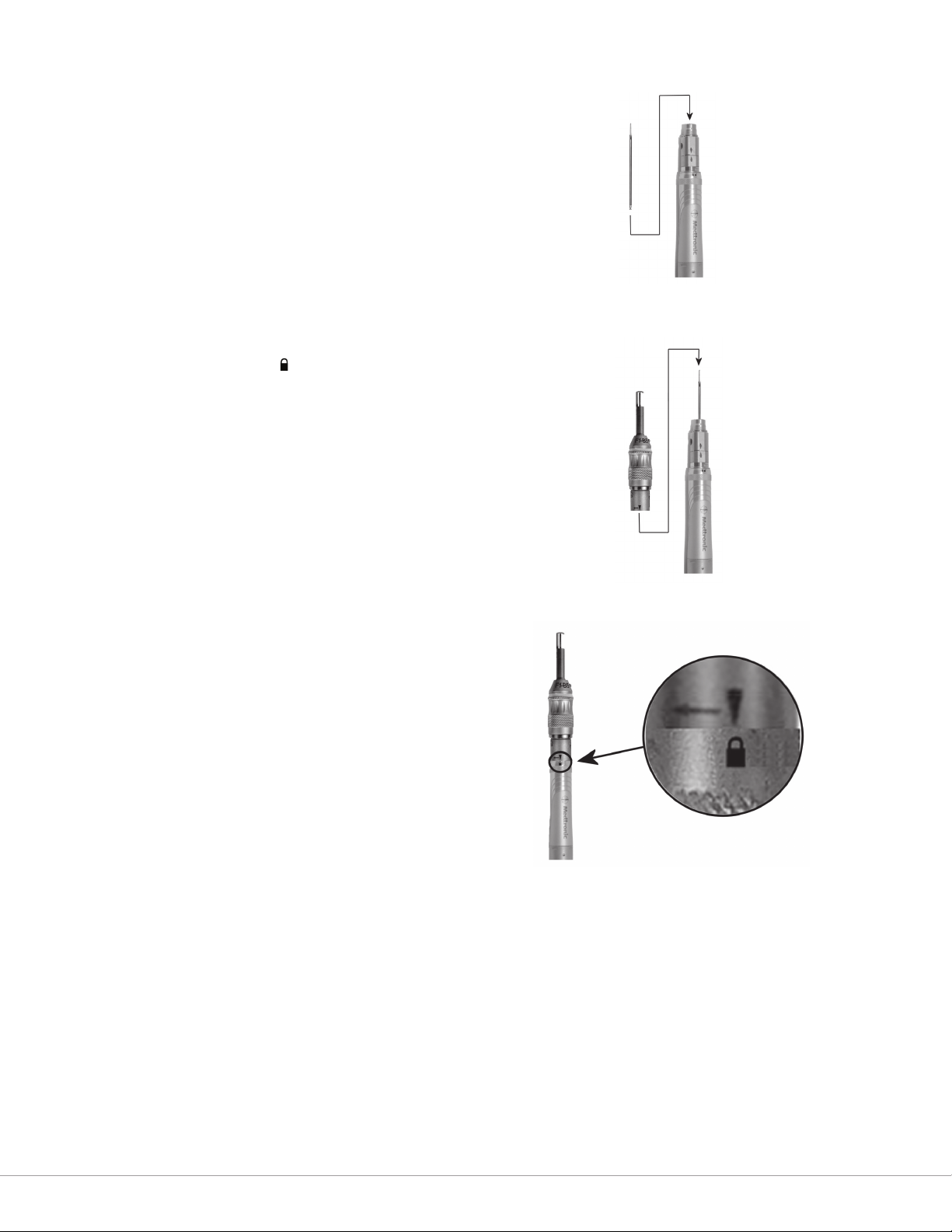
Installation:
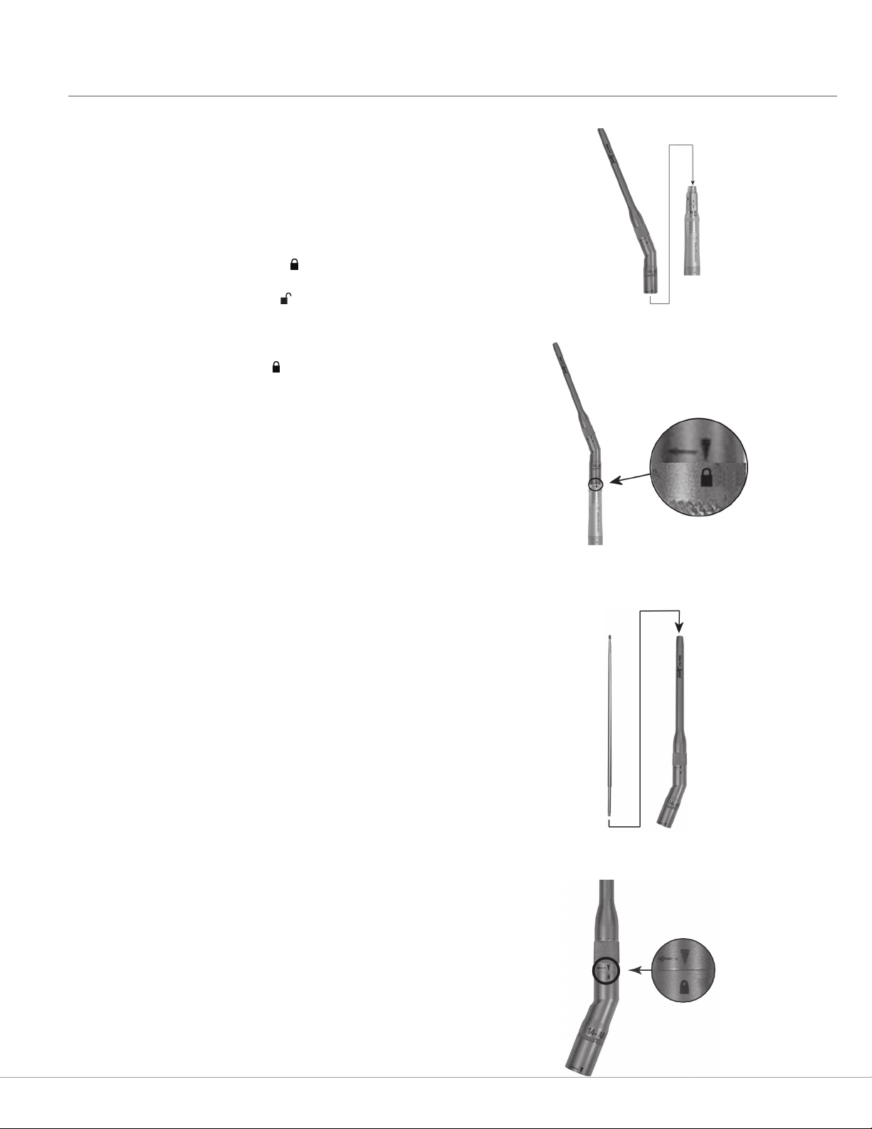
1. Slide the attachment over the motor collet, aligning
the triangular markers (Figure 27). You will feel and
hear the attachment click into place when it is fully
seated.
2. Turn the attachment to the position on the motor
case (Figure 28).
3. With the “tool lock” in the position, insert the
dissecting tool into the attachment with a slight
rotational motion (Figure 29). You will feel and hear
the tool click into place when it is fully seated.
4. Turn the tool lock to the position (Figure 30). Gently
pull on the shaft of the dissecting tool to verify
proper installation.
NOTE: A dissecting tool may be installed in the
attachment before the angled attachment is placed on
the motor.
CAUTION: Hold the handpiece assembly by the
attachment, so that the attachment does not
inadvertently loosen from the handpiece.
Figure 27: Sliding the Attachment over the Motor Collet
Figure 28: Attachment in the Locked Position
Removal:
Removal is the reverse of installation.
Figure 29: Inserting the Dissecting Tool into the Attachment
Figure 30: Tool Lock in the Locked Position
29
Page 35
Appendix A—Specialized Attachments
Angled Double Lock Attachments
Installation:
1. Slide the attachment over the motor collet, aligning
the triangular markers.
2. Pull the attachment towards the motor and turn the
attachment to the position.
3. With the “tool lock” in the position, insert the
dissecting tool into the attachment with a slight
rotational motion. You will feel the tool click into
place when it is fully seated.
4. Turn the tool lock to the position. Gently pull on
the shaft of the dissecting tool to verify proper
installation.
5. On Variable Exposure Attachments, use the TUBE
adjustment ring to adjust the exposure of the
dissecting tool. With the tool pointing away from
you, turn the ring to the right to increase the length
of the tube, thereby decreasing the exposure of the
tool. Turn the ring to the left to decrease the length
of the tube, thereby increasing the exposure of the
tool.
Figure 31: Installing the attachment.
Figure 32: Inserting the Dissecting Tool into the Attachment
Removal:
1. To remove the attachment, hold the motor in the
palm of your hand, and push the sleeve on the
attachment distally while turning the attachment to
the position.
2. Release the sleeve and remove the attachment.
Figure 33: Removing the Attachment
30
Page 36

Appendix A—Specialized Attachments
Curved Bur Attachments
WARNINGS:
• Use adequate irrigation and keep the cooling sleeve
soaked during dissection. Inadequate irrigation may
cause thermal necrosis.
• Do not modify the bur. Bending or prying may break
the bur, causing harm to the patient or operating
room sta.
• Excessive pressure applied to the bur may cause bur
damage. If this occurs, use extreme care to ensure
that all fragments of the bur are removed from the
patient.
• Disposable devices are for single-use only. Do
not attempt to sterilize disposable devices. The
disposables are packed sterile and are not intended
for repeat use. To prevent contamination, use only
once.
• Test for bur wobble (eccentricity) at the desired
speed prior touse. Select a new bur or reduce speed
if wobble is observed prior to use or during the
procedure. Bur wobble may cause patient injury.
Cooling the Bur
1. Prior to initial use, soak the cooling sleeve by dipping
it into a cup of saline or DI water, as shown below.
Wetting of the cooling sleeve prior to cutting
2. During use, maintain copious irrigation of the cooling
sleeve and bur tip by dribbling saline or DI water
along the entire length of the cooling sleeve and bur
tip.
Operation
1. Activate the motor and gently press the curved bur
against the bone to begin dissection.
2. Use a light sweeping motion to continue removing
bone.
Removal
1. Turn both AT10 (V01) locking rings to the position
and pull the bur out of the attachment.
2. Discard the curved bur, according to hospital
procedures.
CAUTIONS:
• Curved burs are not designed for variable tool
exposure. Do not attempt to adjust tool exposure, as
this may damage the device.
• When operating or testing the motor, ensure the
bur is properly inserted and locked into AT10
attachment.
Installation
1. Turn the tube locking ring and the tool locking ring
on the AT10 (V01) Telescoping Attachment into the
position.
2. Slide the curved bur into the AT10 (V01), until the
hub is fully seated.
3. Gently press on the head of the dissecting tool to
lock it into place. You will hear a click when the
curved bur is fully seated.
4. Turn both locking rings to the position on the
AT10 (V01).
5. Gently pull on the curved bur to verify proper
installation.
6. Refer to your motor’s Instruction Manual for
information on setting up the AT10 (V01) attachment
and motor.
7. Briey run the motor with the curved bur installed,
checking for bur wobble or excessive vibration.
If either occurs, perform the corrective actions
described in the Troubleshooting section of these
instructions.
Reuse and Cleaning
Do not reuse.
Sterility
Each bur is gamma-sterilized and is not intended for
repeated use. Do not attempt to re-sterilize.
Cutting Time
Continuous cutting for extended periods may cause the
device to heat to an uncomfortable temperature. To avoid
this, limit cutting to the recommended times below:
Maximum
Continuous
Cutting Time
1 & 2 mm burs 2 minutes 12 minutes
3 & 4 mm burs 3 minutes 12 minutes
Maximum Total
Cutting Time
31
Page 37

Appendix A—Specialized Attachments
Variable Exposure Attachments
CAUTION: The Legend Variable Exposure attachments
can be distinguished from standard attachments by
the dual color bands on the attachment. Match the
color band on the attachment to the color code on the
dissecting tool packaging.
WARNINGS:
• Surgeons should familiarize themselves with the
performance of dissecting tools before use, and
should explore the eect of various levels of tool
exposure on dissection stability. If the tool exhibits
excessive chatter, vibration, or movement, decrease
the tool exposure.
• Dissecting tool size and geometry may contribute
to excessive vibration at certain speeds. Increase or
decrease speed by adjusting the foot/nger control,
or by changing the operating pressure or console
speed setting. If necessary, use a dierent dissecting
tool.
Figure 34: Adjusting Tool Exposure
Installation:
1. Refer to the appropriate section of this manual on
installing xed or angled attachments.
2. After installation, use the TUBE adjustment ring to
adjust the exposure of the dissecting tool (Figure 34).
With the tool pointing away from you, turn the
ring to the right to increase the length of the tube,
thereby decreasing the exposure of the tool. Turn the
ring to the left to decrease the length of the tube,
thereby increasing the exposure of the tool.
WARNING: Do not use the Variable Exposure
Attachment if the TUBE adjustment ring spins freely
or fails to click into place with each adjustment, as the
exposure may change without warning.
CAUTION: Make sure that the tool lock (angled
attachments only) and the attachment lock are still in the
position after each adjustment of the tool exposure.
Attempting to increase the exposure too far may result
in the attachment becoming unlocked. Accidentally
turning the tool lock may result in reduced speed and/or
overheating of the attachment.
WARNING: Do not use the end of the tube as a depth
gauge or depth stop.
Removal:
1. Removal is the reverse of installation.
2. When cleaning, clean the attachment completely,
rst without adjusting the tube length, then with the
tube fully extended, and with the tube fully retracted.
32
Page 38

Appendix A—Specialized Attachments
Footed Attachments
Installation:
1. Insert the dissecting tool into the motor collet with a
slight rotational motion (Figure 35). You will feel and
hear the tool click into place when it is fully seated.
2. Slide the footed attachment over the dissecting
tool, onto the motor, aligning the triangular markers
(Figure 36).
3. Pull the footed attachment towards the motor and
turn the attachment to the position (Figure 37).
Removal:
1. To remove the Legend footed attachment, hold
the motor in the palm of your hand, and push the
sleeve on the attachment distally while turning the
attachment to the position (Figure 38).
WARNING: Remove Legend Footed Attachments
cautiously and slowly per instructions to avoid injury to
the operator.
2. Release the sleeve and remove the attachment.
3. Pull the dissecting tool out of the motor collet and
discard the tool.
Figure 35: Inserting the Tool into the Collet
Figure 36: Sliding the Attachment onto the Motor
Figure 37: Attachment in the Locked Position
Figure 38: Removing the Attachment
33
Page 39
Appendix A—Specialized Attachments
Rotating Footed Attachments
NOTE: Rotating and xed footed attachments with the
same length, marking, and color band share the same
dissecting tools.
Installation:
1. Insert the dissecting tool into the motor collet with a
slight rotational motion (Figure 39). You will feel and
hear the tool click into place when it is fully seated.
2. Slide the attachment over the dissecting tool and
onto the motor, aligning the triangular markers
(Figure 40). You will feel and hear the attachment
click into place when it is fully seated.
3. Turn the attachment to the position (Figure 41).
NOTE: The footed end of the attachment now has 360˚
of unrestricted rotation.
Removal:
Removal is the reverse of installation.
Figure 39: Inserting the Tool into the Collet
Figure 40: Sliding the Attachment onto the Motor
Figure 41: Attachment in the Locked Position
34
Page 40

Appendix A—Specialized Attachments
Contra-Angle Attachment (16-MF)
CAUTION: Do not run the 16-MF attachment with
operating pressure above 80 psi (5.5 bar). This may
cause over-heating and damage to internal gears of
attachment.
Installation:
1. Decrease the pressure at the compressed gas source
to 80 psi (5.5 bar).
2. Adjust the pressure as needed by lowering it at the
gas source, then push down the pressure relief on
the pneumatic control unit to exhaust the excess
pressure in the hoses.
3. Slide the attachment over the motor collet, aligning
the triangular markers (Figure 42). You will feel and
hear the attachment click into place when it is fully
seated.
4. Turn the attachment to the position (Figure 43).
5. Turn the attachment head lever to the open position
(Figure 44).
6. Insert the dissecting tool and return the lever to the
closed position. Gently pull on the dissecting tool
shaft to verify proper installation.
Figure 42: Sliding the Attachment over the Motor Collet
Figure 43: Attachment in the Locked Position
Removal:
1. Removal is the reverse of installation.
2. Discard the dissecting tool after removing it from the
attachment.
NOTE: A dissecting tool may be installed and locked in
the attachment before the Contra-Angle attachment is
installed on the motor.
Figure 44: Opening the Attachment Head Lever
35
Page 41
Appendix A—Specialized Attachments
Metal Cutting Attachments
WARNING: For metal transection, observe the following
safety guidelines:
• Wear eye protection.
• Irrigate well to cool the cutting surfaces.
• Protect the wound site from metal debris.
• Use a clamp or grasping device to control loose
fragments during transection of any metal
component.
The Metal Cutting Attachment uses the tungsten carbide
or diamond wheel dissecting tools.
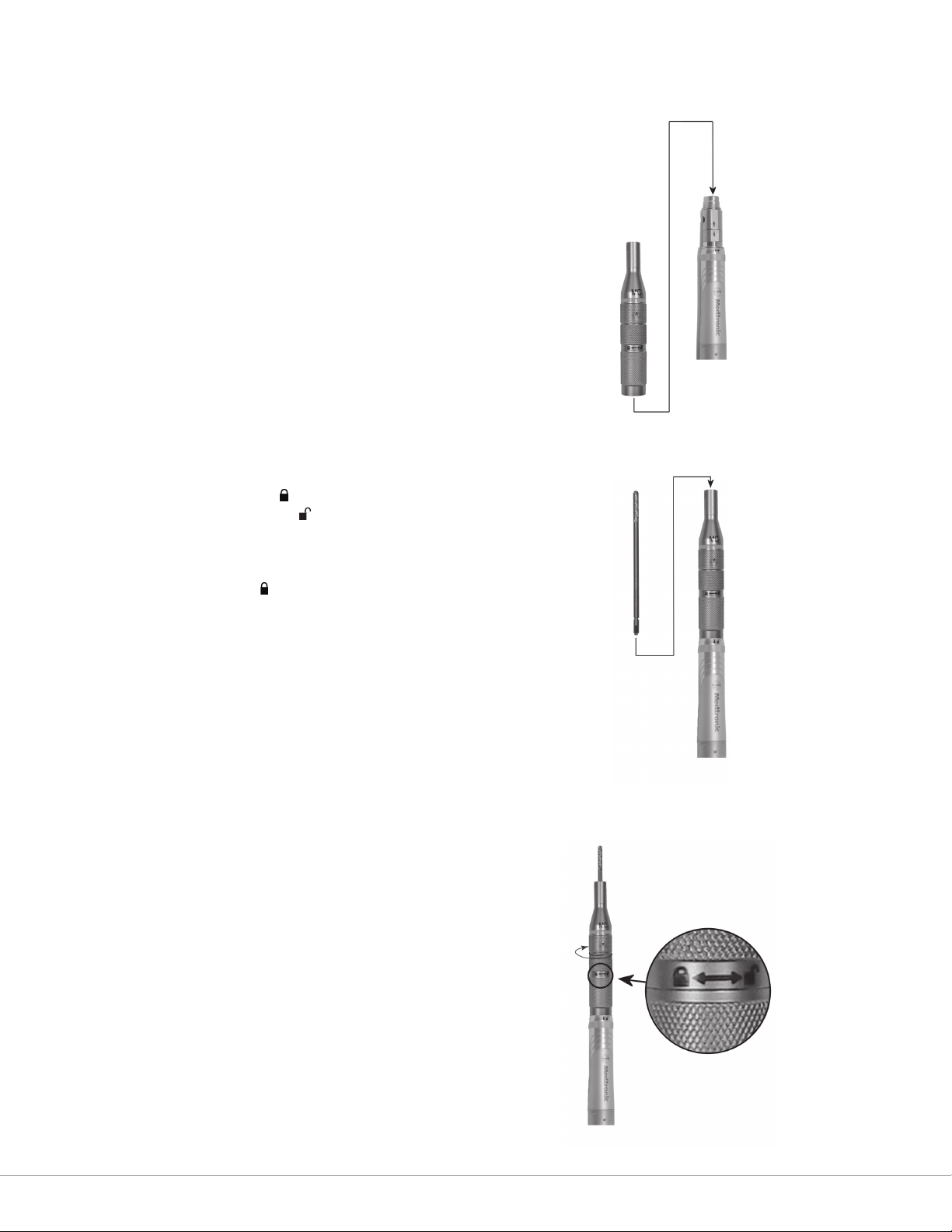
Installation:
1. Slide the attachment over the motor collet aligning
the triangular markers (Figure 45). You will feel and
hear the attachment click into place when it is fully
seated.
2. Turn the attachment to the position.
3. Turn the tool lock towards the icon, and insert
the dissecting tool into the attachment with a slight
rotational motion (Figure 46). You will feel and hear
the tool click into place when it is fully seated.
4. Turn the tool lock to the position (Figure 47). Gently
pull on the shaft of the dissecting tool to verify
proper installation.
NOTE: A dissecting tool may be installed and locked in
the attachment before the metal cutting attachment is
installed on the motor.
Figure 45: Sliding the Attachment over the Motor Collet
Figure 46: Inserting the Tool into the Attachment
Removal:
Removal is the reverse of installation.
WARNING: Do not use metal cutting dissecting tools on
bone.
36
Figure 47: Turning the Tool Lock to the Locked Position
Page 42

Appendix A—Specialized Attachments
Telescoping Attachments
Installation:
1. Slide the attachment over the motor collet aligning
the triangular markers (Figure 48). You will feel and
hear the attachment click into place when it is fully
seated.
NOTE: A dissecting tool may be installed and locked in
the attachment before the telescoping attachment is
installed on the motor.
2. Turn the attachment to the position.
3. Turn the TUBE locking ring towards the icon.
4. Insert the base of the telescoping tube into the
attachment (Figure 49).
5. To lock the tube in place, turn the TUBE locking ring
towards the icon. Do not over tighten.
6. To insert the tool, make sure that the TOOL locking
ring is in the position, and insert the dissecting
tool into the top of the tube (Figure 50). You will
feel and hear the tool click into place when it is fully
seated.
7. Turn the TOOL locking ring to the position. Gently
pull on the shaft of the dissecting tool to verify
proper installation.
8. If the tube position needs to be changed, turn the
TUBE locking ring towards the icon, re-position the
tube, then turn the TUBE locking ring towards the
icon.
Figure 48: Sliding the Attachment over the Motor Collet
Figure 49: Inserting the Telescoping Tube
Figure 50: Inserting the Dissecting Tool
Removal:
1. To remove the attachment, unlock both locking rings,
and pull the telescoping tube and tool out of the
attachment.
2. Turn the attachment to the position and remove it
from the motor.
NOTE: Telescoping tubes are disposable following
multiple uses, and should be discarded when heat or
excessive vibration is noticed, or when insertion of the
tool becomes dicult.
Figure 51: Locking Rings
TUBE Locking Ring
TOOL Locking Ring
37
Page 43

Appendix A—Specialized Attachments
Perforator Driver Attachments
The Perforator Attachment has a Hudson chuck to drive
any device with a Hudson shank, i.e., cranial perforator
device.
NOTE: MPSS does not provide cranial perforator devices.
Installation:
1. Slide the attachment over the motor collet aligning
the triangular markers (Figure 52). You will feel and
hear the attachment click into place when it is fully
seated.
2. Turn the attachment to the position (Figure 53).
3. To install a cranial perforator device with a Hudson
shank, pull back on the collar of the attachment
(Figure 54).
4. Insert the device and release the collar.
NOTE: A cranial perforator device may be installed in
the attachment before the attachment is installed on the
motor.
Removal:
1. To remove the cranial perforator device, pull back on
the collar of the attachment.
2. To remove the attachment, turn it to the position
and slide it o of the motor.
WARNING: Consult the cranial perforator device labeling
for the recommended speed specications.
Figure 52: Sliding the Attachment over the Motor Collet
Figure 53: Attachment in the Locked Position
Maximum Speed of Perforator Attachments
Gas Pressure
(Dynamic)
80 psi 660 rpm 850 rpm
100 psi 820 rpm 1050 rpm
120 psi 890 rpm 1140 rpm
Model AD01
Output Speed
(Max.)
Model AD03
Output Speed
(Max.)
Figure 54: Pulling Back on the Collar
38
Page 44

Appendix A—Specialized Attachments
Jacobs® Chuck Attachments
The Jacobs Chuck attachment is a non-cannulated 5/32”
chuck with key for drilling.
Installation:
1. Slide the attachment over the motor collet aligning
the triangular markers (Figure 55). You will feel and
hear the attachment click into place when it is fully
seated.
2. Turn the attachment to the position (Figure 56).
3. To install a drill bit, turn the Jacobs key to open the
collar.
4. Insert the drill bit and tighten the collar.
NOTE: A drill bit may be installed in the attachment
before the Jacobs Chuck attachment is installed on the
motor.
Removal:
Removal is the reverse of installation.
Figure 55: Sliding the Attachment over the Motor Collet
Figure 56: Attachment in the Locked Position
39
Page 45

Appendix A—Specialized Attachments
Bone Mill Attachment
The Legend Bone Mill attachment is composed of
a non sterile base and gamma-sterilized, single use
disposable components. The gamma-sterilized single
use disposable components consist of one bowl, one cap
(with LOW and HIGH settings), and one spatula. A Legend
or MR7 motor provides the power to drive the Bone Mill
attachment. The Bone Mill attachment is intended to mill
bone into particles 1 to 5mm in size.
WARNINGS:
• Do not operate the Bone Mill attachment without
the bowl, and cap secured in place.
• Do not come in contact with the interior of the
disposable bowl and cap during bone milling.
• Do not use the Bone Mill disposable components for
more than one surgical procedure, as this may cause
cross-contamination and aect patient safety.
• Use only Legend/MR7 motors and Legend Bone
Mill disposables in combination with the Bone
Mill attachment. Use of other devices will void the
manufacturer’s warranty.
Figure 57: Bone Mill Attachment
1. Cap
2. Bowl
3. Bone Mill Base
4. Motor
5. Spatula
Figure 58: Bone Mill Cap
5
HIGH
LOW
1
2
3
4
Using the Bone Mill Attachment
1. Place the bowl onto Bone Mill base and secure the
latches.
2. Lay harvested bone specimens into the bowl.
CAUTIONS:
• The addition of any liquid to the milling process
should be administered in small volumes to prevent
leakage.
• Do not use Bone Mill disposables to process more
than 6 bone pieces approximately 1.5 cc in size at
one time.
• Do not use Bone Mill disposables to process more
than a total of 40 cc of bone during any one surgical
procedure.
3. Secure the cap onto the bowl by rotating
counterclockwise. Do not activate the Bone Mill
Attachment without securing the cap.
4. Use the HIGH cap position when starting with large
pieces of bone or large batch amounts. Use the LOW
cap position to nish milling a batch or when starting
with small pieces or batch amounts (Figure 58).
5. Insert the motor into the motor connection on the
Bone Mill base and rotate the motor to the position
(Figure 59).
6. Activate the motor to mill bone. Continue to run the
Bone Mill Attachment until desired bone particle size
is achieved. Adjust motor speed to obtain desired
particle size.
Figure 59: Inserting the Motor
40
Page 46

NOTE: If bone does not process, deactivate the motor,
rotate the motor to the position, and remove the cap.
Reinsert the cap in the HIGH position and activate the
motor. If bone spins without milling or jams, divide bone
chunks into two batches and process separately.
7. Process the bone for 5–15 seconds and visually check
to gauge quality of milling before continuing.
8. Continue to process bone in 5–15 second batches
until the majority of particles reach desired size.
9. To remove bone particles stop operation of the
motor and rotate it to the position. Remove the
cap by rotating it clockwise. Use the spatula inside
the bowl and cap to remove bone particles.
NOTES:
• Milling time is dependent on the density of the
patient’s bone, the ratio of cancellous and cortical
bone, the size of the individual particles and the
batch amount of the bone to be processed. Always
check bone after 10–15 seconds to gauge quality of
milling.
Appendix A—Specialized Attachments
• If the blade becomes inoperable, stop operation of
the motor and rotate the motor to the position.
Remove the cap and use the spatula to free bone
and/or blades.
• After removing bone particles from the bowl, the
milling process may be repeated with additional
bone specimens, as needed. (Up to a total of 40 cc of
bone may be processed by the Bone Mill Disposable
during any one surgical procedure.)
After Use
1. Rotate the motor to the position.
2. Unlatch the Bone Mill disposables from the base.
3. Discard the bowl, cap, and spatula per hospital
procedure.
4. Clean the Bone Mill base according to the directions
below.
5. Clean the motor according to its instruction manual.
Bone Mill bowl, cap, and spatula are single use
devices. Opened but unused Bone Mill disposables
may not be re-sterilized under any sterilization
method.
Preventative Maintenance
The Bone Mill Attachment should be returned for factory
maintenance annually (approximately 100 procedures).
If the Bone Mill Attachment does not function according
to these instructions, call your Medtronic Regional
Distributor or Medtronic Neurologic Sales Representative.
If necessary, return the Bone Mill Attachment base to
your Distributor or Sales Representative to be repaired.
41
Page 47

Page 48

175031EN.RE
©2009, 2015, 2016 Medtronic, Inc.
2016-05
Manufactured by:
Medtronic Powered Surgical Solutions
4620 North Beach Street
Fort Worth, TX 76137 USA
Telephone: 817-788-6400
Toll-Free: 1-800-643-2773
Fax: 817-788-6401
www.medtronic.com
Orders:
Telephone: 817-788-6400
Toll-Free: 1-800-433-7080
Fax: 817-788-6489
Repairs:
Telephone: 817-788-6440
Toll-Free: 1-800-335-9557
Fax: 817-788-6441
EC Authorized Representative:
Medtronic B.V.
Earl Bakkenstraat 10
6422 PJ Heerlen
The Netherlands
Medtronic Australian Sponsor:
Medtronic Australasia Pty Ltd
5 Alma Road
Macquarie Park, NSW 2113 Australia
 Loading...