


Instructions for Use
175002EN G
Midas Rex™ Legend™ Pneumatic High-Speed System
Legend Gold™, Legend Gold Touch™, Legend Platinum™, Midas Rex
MR7™, and Midas Rex MR7 Touch™

Customer service
Contact your Medtronic Neurosurgery sales representative or call:
Medtronic Neurosurgery Service Group
(800) 433-7080 or (817) 788-6440
RS.DFWrepairs@medtronic.com
Outside the U.S.A., contact your Medtronic regional distributor or Medtronic Neurosurgery representative.
EN To obtain a copy of this manual in your local language contact your local Medtronic representative or go to
manuals.medtronic.com.
FR Pour obtenir un exemplaire de ce manuel dans votre langue, veuillez contacter votre représentant Medtronic local
ou visiter la page manuals.medtronic.com.
IT Per ottenere una copia del presente manuale nella lingua locale, contattare il rappresentante Medtronic di zona o
visitare la pagina manuals.medtronic.com.
DE Eine Kopie dieses Handbuchs in der jeweiligen Landessprache kann vom örtlichen Medtronic-Vertreter angefordert
oder unter manuals.medtronic.com bezogen werden.
ES Para obtener una copia de este manual en su idioma local, póngase en contacto con su representante local de Medtronic
o visite manuals.medtronic.com.
NL Neem contact op met uw vertegenwoordiger van Medtronic of ga naar manuals.medtronic.com voor een exemplaar
van deze handleiding inuwtaal.
DA Du kan få en kopi af denne vejledning på dit sprog ved at kontakte den lokale Medtronic-repræsentant eller gå til
manuals.medtronic.com.
SV För att erhålla en kopia av denna handbok på ditt språk kontaktar du din lokala representant för Medtronic eller går
till manuals.medtronic.com.
FI Jos haluat tämän käyttöoppaan omalla kielelläsi, ota yhteyttä paikalliseen Medtronicin edustajaan tai siirry osoitteeseen
manuals.medtronic.com.
PT-PT Para obter uma cópia deste manual no seu idioma local, contacte o seu representante local Medtronic ou visite
manuals.medtronic.com.
EL Για να λάβετε αντίγραφο του παρόντο εγχειριδίου στην τοπική σα γλώσσα, επικοινωνήστε ε τον τοπικό αντιπρόσωπο
τη Medtronic ήεπισκεφθείτε την ιστοσελίδα manuals.medtronic.com.
PL Aby uzyskać egzemplarz niniejszego podręcznika w wybranym języku, należy się skontaktować z lokalnym
przedstawicielem rmy Medtronic lubodwiedzić stronę manuals.medtronic.com.
CS Máte-li zájem okopii této příručky vmístním jazyce, kontaktujte místního zástupce společnosti Medtronic nebo navštivte
webové stránky manuals.medtronic.com.
HU Ha szeretne egy saját nyelvű példányt a jelen kézikönyvből, vegye fel a kapcsolatot a Medtronic helyi képviseletével,
vagy látogasson el a manuals.medtronic.com weboldalra.
TR Bu kılavuzun kendi dilinizde bir kopyasını almak için, bölgenizdeki Medtronic temsilcinize bavurun veya
manuals.medtronic.com adresine gidin.
NO Du kan få et eksemplar av denne håndboken på ditt språk ved å kontakte din lokale Medtronic-representant eller gå
til manuals.medtronic.com.
RU Medtronic
manuals.medtronic.com.
SR Da biste dobili kopiju ovog priručnika za korisnike na svom jeziku, kontaktirajte lokalno predstavništvo kompanije
Medtronic ili posetite lokaciju manuals.medtronic.com.
HR Da biste dobili kopiju ovog priručnika na svom jeziku, obratite se lokalnom predstavniku tvrtke Medtronic ili pak posjetite
web-mjesto manuals.medtronic.com.
PT-BR Para obter uma cópia deste manual em seu idioma local, entre em contato com o representante local da
Medtronic ou acesse manuals.medtronic.com.
The information contained in this document is accurate at time of publication. Medtronic reserves the right to make changes to the product described
in this manual. Refer to manuals.medtronic.com for the current version.
The following are trademarks or registered trademarks of Medtronic, Inc. in the United States and other countries: Legend™, Legend Gold™,
Legend Gold Touch™, Legend Platinum™, Midas Rex™, MR7™, MR7 Touch™, MEDNEXT™, and Triton™. All other trademarks, service marks,
registered trademarks or registered service marks are the property of their respective owners in the United States and other countries.

Contents
Glossary .............................................................................................................................................................................................................1
Indications for use .........................................................................................................................................................................................1
Device description ........................................................................................................................................................................................1
Contraindications ..........................................................................................................................................................................................1
No latex policy ................................................................................................................................................................................................1
Important safety instructions ...................................................................................................................................................................1
Warnings ...........................................................................................................................................................................................................1
System warnings ..................................................................................................................................................................................1
Component warnings ........................................................................................................................................................................2
Tools and disposable components warnings ............................................................................................................................2
Legend pneumatic control unit warnings ..................................................................................................................................3
Legend lubricant/diuser cartridge warnings ..........................................................................................................................3
Cautions ............................................................................................................................................................................................................3
Legend system motors ................................................................................................................................................................................4
Legend Gold ..........................................................................................................................................................................................4
Legend Gold Touch .............................................................................................................................................................................4
Legend Platinum..................................................................................................................................................................................4
Legend accessories .......................................................................................................................................................................................5
Legend pneumatic control unit .....................................................................................................................................................5
Regulator ................................................................................................................................................................................................5
Regulator hose .....................................................................................................................................................................................5
Legend instrument case ...................................................................................................................................................................5
Motor wrench .......................................................................................................................................................................................5
Lubricant/diuser cartridge (PA100-A) ........................................................................................................................................5
Adapters ..................................................................................................................................................................................................6
Attachments ..........................................................................................................................................................................................6
Dissecting tools ....................................................................................................................................................................................6
Legend power source requirements ......................................................................................................................................................7
Legend pneumatic connections ..............................................................................................................................................................7
Legend pneumatic motor technical specications ...........................................................................................................................8
Legend system assembly ............................................................................................................................................................................8
Installing the lubricant/diuser cartridge (PA100-A) and connecting the Legend motor to the control unit .........8
Legend pneumatic control unit activation ................................................................................................................................9
Midas Rex MR7 system motors .................................................................................................................................................................10
MR7 ...........................................................................................................................................................................................................10
MR7 Touch ..............................................................................................................................................................................................10
MR7 accessories .............................................................................................................................................................................................11
MR7 pneumatic control unit ............................................................................................................................................................11
Regulator ................................................................................................................................................................................................11
Regulator hose .....................................................................................................................................................................................11
MR7 instrument case ..........................................................................................................................................................................11
Motor wrench .......................................................................................................................................................................................11
Lubricant/diuser cartridge (PA700) ............................................................................................................................................11
Adapters ..................................................................................................................................................................................................12
Attachments ..........................................................................................................................................................................................12
Dissecting tools ....................................................................................................................................................................................12
MR7 power source requirements ............................................................................................................................................................13
MR7 pneumatic connections ....................................................................................................................................................................13
MR7 pneumatic motor technical specications .................................................................................................................................14

MR7 system assembly ..................................................................................................................................................................................14
Installing the lubricant/diuser cartridge (PA700) and connecting the MR7 motor to the control unit ....................14
MR7 pneumatic control unit activation .......................................................................................................................................15
Legend Gold, Legend Gold Touch, Legend Platinum, MR7, and MR7 Touch lock ..................................................................16
Legend Gold Touch and MR7 Touch safety slide ................................................................................................................................16
Legend Gold, Legend Gold Touch, Legend Platinum, MR7, and MR7 Touch tools and attachments .............................17
Dissecting tool nomenclature.........................................................................................................................................................17
General guidelines for attachments and tool applications ............................................................................................................18
Attachment assembly and disassembly ................................................................................................................................................22
Straight attachment ...........................................................................................................................................................................22
Angled attachment .............................................................................................................................................................................23
Fixed footed attachment ..................................................................................................................................................................23
Rotating footed attachment ............................................................................................................................................................24
Contra-angle attachment AC-16 ....................................................................................................................................................24
Metal cutting attachment ................................................................................................................................................................25
Variable exposure straight and angled attachment ...............................................................................................................25
Telescoping tube and telescoping tube base attachment straight (AT10) and angled (AT10A) ................................26
Telescoping curved bur and telescoping base attachment straight (AT10) and angled (AT10A) ..........................26
Perforator (AD01 & AD03) attachment ........................................................................................................................................27
Jacobs chuck attachment .................................................................................................................................................................27
Angled double lock (DK) attachment ..........................................................................................................................................27
J-latch attachment ..............................................................................................................................................................................28
Bone mill attachment.........................................................................................................................................................................28
Material safety data sheet for lubricant .................................................................................................................................................28
Legend system troubleshooting ..............................................................................................................................................................29
Legend motors .....................................................................................................................................................................................29
Legend attachments or telescoping tubes ................................................................................................................................30
Legend dissecting tools ....................................................................................................................................................................31
Disassembly of Legend equipment ........................................................................................................................................................32
Disassembly of MR7 equipment ..............................................................................................................................................................32
Cleaning and sterilization ...........................................................................................................................................................................33
Cleaning brushes .................................................................................................................................................................................33
Legend pneumatic motors reprocessing instructions ...........................................................................................................33
Pneumatic control unit reprocessing instructions ..................................................................................................................34
Attachments/tubes reprocessing instructions ........................................................................................................................34
Return policy for devices exposed to Transmissible Spongiform Encephalopathies (TSE) ....................................................36
Preventative maintenance .........................................................................................................................................................................36
Legend pneumatic high speed preventive maintenance/service program .................................................................36
Dening maintenance level .............................................................................................................................................................36
Section 1: Preventive maintenance/service schedule: 12 maintenance intervals ...........................................................37
Section 2: Instructions for completing preventive maintenance steps ...........................................................................37
Refurbishing or repairs ................................................................................................................................................................................40
Contact ....................................................................................................................................................................................................40
Midas Rex Legend pneumatic high speed system limited warranty* ........................................................................................40
Symbols ............................................................................................................................................................................................................41

Midas Rex™ Legend™ Pneumatic High-Speed System
Glossary
PCU Pneumatic Control Unit
Indications for use
The Medtronic Midas Rex Legend System is a pneumatically operated surgical instrument system. The pneumatic motor provides power to operate removable
rotating surgical cutting tools and their accessories intended for use in neurosurgery, including craniotomy and spinal surgery; as well as Ear Nose and Throat (ENT),
orthopedic, and general surgical applications including maxillofacial, craniofacial, and sternotomy surgeries.
Additionally, the Legend System is indicated for the incision/cutting, removal, and drilling of soft and hard tissue, bone, and biomaterials during open and minimally
invasive spine procedures, which may incorporate application of various surgical techniques during the following lumbar spinal procedures
• Lumbar Microdiscectomy • Transforaminal Lumbar Interbody Fusion (TLIF)
• Lumbar Stenosis Decompression • Anterior Lumbar Interbody Fusion (ALIF)
• Posterior Lumbar Interbody Fusion (PLIF) • Direct Lateral Interbody Fusion (DLIF)
Device description
The Legend pneumatic high speed system is a powered drill system that is used to remove soft tissue, hard tissue, and bone during surgical procedures. The system
consists of a motor that powers/rotates the cutting media, attachments that are used to provide support and stability to the dissecting tools, and dissecting tools
that perform the task of removing soft and hard tissue and bone.
The Legend system is comprised of the following:
• Legend Gold, Legend Gold Touch, or Legend Platinum motors • Legend dissecting tools — single use, disposable
• Legend pneumatic control unit with regulator and various connectors • Legend lubricant/diuser — single use, disposable
• Legend attachments
The MR7 system is part of the Legend pneumatic high speed system and is comprised of the following:
• MR7 or MR7 Touch motors • MR7 TRITON adapter (optional)
• MR7 pneumatic control unit with regulator and various connectors • MR7 lubricant/diuser — single use, disposable
The MR7 system uses the same attachments and dissecting tools as the Legend Pneumatic High-Speed System.
The Legend system is designed for use by medical professionals familiar with powered surgical instrumentation. The surgeon is responsible for learning the proper
techniques in the use of this system, as inappropriate use may potentially be harmful. It is strongly recommended that the surgeon and dedicated operating room personnel
are knowledgeable in the use of this equipment by being trained in Medtronic Midas Rex Hands-On Workshops or by one of the local authorized representatives.
Contraindications
None.
No latex policy
Medtronic Powered Surgical Solutions (MPSS) guarantees that all Legend equipment and products identied in this manual, manufactured by and/or for MPSS, do
not contain latex.
MPSS’s packaging materials, labels, pouches, package inserts, or similar items do not contain latex.
Important safety instructions
The words Warning, Caution, and Note carry special meanings and should be carefully reviewed.
Warning: The personal safety of the patient, operator, and/or operating room sta may be involved. Disregarding this information could result in injury to the patient,
operator, and/or operating room sta.
Caution: These instructions point out special service procedures or precautions that must be followed to avoid damaging the instrument. A damaged instrument
could result in injury to the patient, operator, and/or operating room sta.
Note: This provides special information to make maintenance easier or important operating instructions more clear.
Read and understand warnings before use of the Legend system.
Warnings
System warnings
W1 The Legend pneumatic system operator must be familiar with this Instructions for Use, their precautions, procedures, and safety issues.
W2 The Legend pneumatic system and its associated equipment should be used only by qualied medical professionals who are thoroughly trained and
experienced in performing surgery with Medtronic high speed surgical drills.
W3 Heavy side loads and/or long operating periods may cause the device to overheat.
W4 The Legend pneumatic motors should only be operated when the attachment is in the locked position.
W5 Do not use excessive force to pry or push bone with the attachment or dissecting tool during surgery.
W6 Use only dissecting tools specically designed for use with this drill system. Match the nomenclature and color code on the tool packaging to the same
nomenclature and color code on the attachment.
W7 Do not use the Legend pneumatic system without proper cleaning and sterilization.
W8 Do not operate the Legend pneumatic motors in the presence of magnetic resonance imaging (MRI) devices.
W9 For metal transection, observe the following safety precautions:
W9a Wear eye protection.
W9b Irrigate well to cool cutting surfaces.
W9c Protect wound site from metal debris.
W9d Use a clamp or grasping device to control loose fragments during transection of any metal component.
W10 All service must be performed by Medtronic qualied personnel only.
W11 Do not attempt to use a motor that is leaking lubricant.
W12 Do not place motor, attachment, and dissecting tool on the patient or in an unsecured location during surgery.
1

Midas Rex™ Legend™ Pneumatic High-Speed System
W13 Do not pinch, kink, obstruct, cut, tear, or step on the motor/exhaust hose. This may cause the hose to rupture and may injure the patient or user.
W14 Do not use damaged, faulty, or modied Legend pneumatic system components. Inspect the system components for damage prior to each use.
W15 Do not use components except for Medtronic Midas Rex Legend attachments, Legend dissecting tools, and Legend accessories in combination with a Legend
pneumatic motor. Use of devices other than Legend systems or associated parts or components may cause injury to the patient, operator and/or operating room sta.
Use of devices other than Legend Systems or associated parts or components will damage the motor and attachments and will void manufacturer’s limited warranty.
W16 Do not dissect bone without adequate irrigation to prevent thermal necrosis.
W17 Do not operate a Legend pneumatic motor without eyewear protection.
W18 Do not use a Legend pneumatic motor if the motor continues to run after releasing the foot pedal or nger control. Return to Medtronic for service.
W19 Do not remove Legend Gold Touch motor or MR7 Touch motor from pneumatic control unit unless compressed gas has been released from the hoses.
W20 Do not use an overheated device, as it may cause thermal injury to the patient or operator.
W21 To avoid injury when using the Legend Gold Touch motor or MR7 Touch motor, ensure the safety slide is in the “O” position before installing the attachment and tool.
W22 Place Legend Gold Touch and MR7 Touch motors in Safe mode while not in use.
Component warnings
W23 Do not use any parts other than Medtronic system components as damage or substandard performance could result.
W24 Always inspect the components before and after use for any damage. If damage is observed, do not use damaged component until it is repaired by Medtronic
qualied personnel or replaced. Damaged parts may deposit metal shavings on surgical site or may cause injury.
W25 Employ visualization, including use of imaging techniques (for example, uoroscopy, image guided surgery) when using rotating powered accessories. Discontinue
powered application in the event of lack of visualization of surgical site.
W26 When using Midas Rex Legend variable exposure attachments, surgeons should become familiar with the performance of dissecting tools before use and should
explore the eect of various levels of tool exposure on tool stability. If the tool exhibits excessive chatter, vibration, or movement, decrease the tool exposure.
W27 Motors and attachments may fail due to extended use resulting in component(s) detaching and falling from the motor or attachment, causing patient injury.
To avoid this, motors and attachments should be serviced periodically at intervals recommended by Medtronic.
W28 Use adequate irrigation. The use of a tool without irrigation may cause heat buildup resulting in a thermal injury to tissue.
W29 Do not attempt to change a dissecting tool or attachment while the motor is running or when the motor or attachment is in an overheated state.
W30 Do not immerse the system components, except as noted.
W31 A device that is not functioning properly should not be used until the unit is repaired and tested by Medtronic to ensure that it is functioning in accordance with
Medtronic specications.
W32 When using Midas Rex Legend variable exposure attachments, ensure that the attachment is still in the locked position after each adjustment of the tool exposure.
Attempting to increase the tool exposure too far may result in the attachment accidentally being unlocked.
W33 The Legend pneumatic motors will not run properly unless the attachment is in the locked position.
W34 Midas Rex Legend pneumatic motors should only be operated when the attachment is in the fully locked position. Smoke and/or excessive heat may be generated
if attachment is not in the fully locked position. This may result in thermal injury to the user or sta.
W35 Do not change an accessory with the motor running to prevent laceration of user and/or cross-contamination through compromised glove.
W36 Remove Legend footed attachments cautiously and slowly as per instructions to avoid injury to the operator.
W37 Do not modify accessories used with the motor. Performance could be diminished with modied accessories.
W38 Verify reusable device was cleaned and/or sterilized prior to use. If not, do not use.
W39 Sterilize and dry reusable device before storing. Decrease likelihood of cross-contamination with timely sterilization. After each procedure, properly clean and
sterilize all reusable system components.
W40 Excessive side loading could cause non-DK angled attachments to unlock accidentally from motor.
W41 Ensure proper installation of tool in footed attachment. Failure to follow instructions may result in the tool tip contacting the foot of the attachment causing
damage to the attachment and/or harm to patient.
W42 Any tubing or other tip protectors used during shipping must be removed prior to cleaning and sterilization.
W43 Any device that has not been used in a four-year period should be serviced by Medtronic to ensure its performance.
W44 Ensure the adapter is fully threaded onto the regulator hose and that the adapter is fully threaded/connected to the corresponding wall outlet before operating
the pneumatic system.
W45 Do not operate the bone mill attachment without the bowl and cap secured in place.
W46 Do not come in contact with the interior of the disposable bowl and cap during bone milling.
W47 Do not use the bone mill disposable components for more than one surgical procedure, as this may cause cross-contamination and aect patient safety.
W48 Use only Medtronic Legend/MR7 and Legend bone mill disposables in combination with the bone mill attachment.
W49 Legend Gold, Gold Touch, and Platinum instrument case (PA400) is not interchangeable with MR7 and MR7 Touch instrument case (PA600). Utilize appropriate
case when sterilizing motors.
Tools and disposable components warnings
W50 Keep the cutting area of the tool away from ngers and loose clothing to prevent laceration of user and cross-contamination through compromised glove.
W51 Operate the tool only after appropriate anatomical landmarks at the intended surgical site have been conrmed.
W52 Use care in application of the rotating cutting end to only appropriate anatomical landmarks and the intended surgical site when using powered accessories.
W53 Bending or prying may break the accessory, causing harm to patient or user.
W54 A tool’s size and geometry may create excessive vibration at certain speeds. Increase or decrease speed of the motor to prevent vibration.
W55 Test for wobble at desired speed prior to use. Discontinue use of accessory if tool tip wobbles and replace accessory to prevent unintended tissue removal.
W56 Carefully inspect dissecting tool both prior to and following each use for signs of excessive wear, fragmentation, eccentricities, or other defects. Replace any
suspicious dissecting tools with a new one prior to use.
W57 Excessive noise from the tool when drilling close to the cochlea or ossicular chain may cause hearing damage.
W58 Tools with “L” identication are longer tools intended for light bone dissection. The increased tool head/stem conguration may aect dissection stability.
W59 Do not re-sharpen used tools. Worn tools should be frequently replaced with new ones to ensure eective cutting and control.
W60 Excessive pressure applied to bur may cause bur fracture. Should a tool fracture in use, extreme care must be exercised to ensure that all fragments of the tool
are removed from the patient.
W61 Do not use metal-cutting tools to cut/resect bone.
W62 Use only rotary tools specically designed for use with the Medtronic Midas Rex Legend drill system.
W63 Do not use an accessory if its packaging is opened or damaged. Sterility may be compromised if packaging is opened or damaged.
2

Midas Rex™ Legend™ Pneumatic High-Speed System
W64 Properly dispose of single-use devices removed from sterile packages. Devices lose sterility upon removal from packaging.
W65 Do not use dull tools. Use of dull tools can reduce cutting eectiveness and can cause the motor temperature to increase.
W66 Always ensure that the tool is secured in the motor or attachment prior to operating the system.
W67 Exposure of tool packaging to light for extended periods of time may cause damage to packaging.
W68 Do not use or re-process a dissecting tool that has already been used. Using a dissecting tool that has already been used may cause injury to the patient, operator
and/or operating room sta or contamination. Using a dissecting tool that has already been used may aect motor performance.
W69 Do not use an attachment and dissecting tool combination if tool ail or excessive vibration occurs.
W70 Dissecting tool utes are sharp and may perforate surgical gloves.
Legend pneumatic control unit warnings
W71 Do not use the Legend pneumatic control unit to operate any other systems except for Legend pneumatic motors and TRITON Power Surgical Instrument Systems.
W72 Do not disassemble equipment before gas pressure is released from Legend pneumatic control unit and associated hoses.
W73 Do not carry Legend pneumatic control unit by the N2 DISS pressure hose.
W74 Do not use the pneumatic control unit to operate systems other than the Midas Rex and TRITON pneumatic systems.
Legend lubricant/diuser cartridge warnings
W75 Failure to properly secure Legend lubricant/diuser cartridge may cause injury to operator and/or operating room sta.
W76 Do not attempt to remove the lubricant/diuser cartridge while the system is pressurized.
W77 Do not use a Legend pneumatic motor without a lubricant/diuser installed.
W78 Do not use a lubricant/diuser cartridge if it appears to be damaged, or if the inner foil seal is punctured.
Cautions
C1 When using an angled attachment, hold the motor assembly by the attachment so that the attachment does not inadvertently loosen from the motor.
C2 Do not use twist drill or contra-angle tool/attachment at an operating pressure over 80 psi (5.5 bar).
C3 Do not kink hoses. Inspect hoses for cracks, tears, or corrosion.
C4 The use of a washer-disinfector for cleaning may cause a pre-mature degradation in performance.
C5 Remove devices from instrument case before placing into washer-disinfector and allow devices to drain. Orient devices in the washer-disinfector by following
manufacturer recommendations.
C6 Do not use low-temperature hydrogen peroxide gas plasma sterilization due to the lumen internal diameter and length restrictions.
C7 Do not use low-temperature liquid peracetic acid sterilization due to immersion procedure.
C8 Remove and discard accessories following local regulations for disposal of contaminated materials.
C9 Do not run the motor at an operating pressure above or below the required operating pressure range. Operating pressure below 80 psi (5.5 bar) may not
provide proper lubrication to the motor. Operating pressure above 120 psi (8.3 bar) may damage or reduce the life of the motor.
C10 Do not autoclave the pneumatic adapter.
C11 Legend pneumatic control unit and pressure hose should not be sterilized.
C12 Do not exceed 1 hour drill time per surgery for a Legend lubricant/diuser.
C13 Use only Legend dissecting tools with a Legend pneumatic motor.
C14 Do not attempt to remove Legend lubricant/diuser while the motor is in operation.
C15 Do not attempt to rell a used lubricant/diuser cartridge.
C16 Do not sterilize the lubricant/diuser cartridge. The lubricant/diuser cartridge may melt into the lubricant/diuser housing with potential damage to the
motor. The lubricant/diuser cartridge must be removed from the motor’s lubricant/diuser housing prior to sterilization.
C17 When using angled attachments with the Legend Gold Touch, extend the lever on the Finger Control and hold by the attachment.
C18 If the motor has an uncomfortable temperature to touch/ hold following sterilization, allow an adequate “cool down” period.
C19 If the motor has an uncomfortable temperature to touch/ hold and an adequate “cool down” period was used, check that a new Legend lubricant/diuser is
properly attached to the motor’s lubricant/diuser housing to help cool down motor. Run the motor briey to assist in its cool down.
C20 The Legend Gold, Gold Touch, and Platinum lubricant/diuser cartridge (PA100-A) is not interchangeable with the MR7 lubricant/diuser cartridge (PA700).
Ensure you select the appropriate lubricant/diuser cartridge for the motor.
C21 During a lengthy surgical procedure with extended motor use, lubricant may drip from lubricant/diuser cartridge.
C22 Do not re-use a lubricant/diuser cartridge. It is a single-use product.
C23 Remove lubricant/diuser cartridge from motor assembly prior to sterilizing it.
3
Midas Rex™ Legend™ Pneumatic High-Speed System
1
2
3
4
5
1
2
3
4
5
7
6
8
1
2
3
4
5
Legend system motors
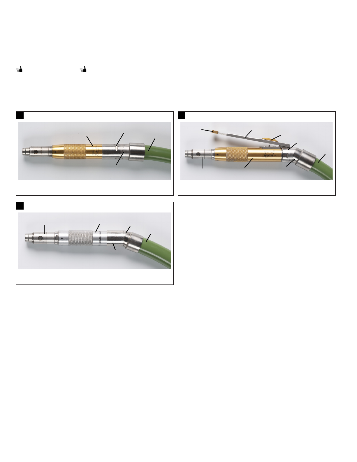
Legend Gold
High speed, high torque pneumatic motor (Figure 1-1) used to dissect bone and biomaterials.
Legend Gold Touch
High speed, high torque pneumatic motor (Figure 1-2) with a variable speed nger control used to dissect bone and biomaterials.
Instruction manual will use “ ” symbol to indicate information on Legend Gold Touch.
Legend Platinum
High speed, compact pneumatic motor (Figure 1-3), with a reduced sound output and slightly decreased power when compared to the Legend Gold and Gold Touch
used to dissect bone and biomaterials.
Warning: Refer to Warnings W1.
1-1
1. Collet
2. Motor case
1-3
1. Collet
2. Motor case
Legend Gold motor Legend Gold Touch motor
3. Swivel
4. Convertible angle
Legend Platinum motor
3. Swivel
4. Fixed angle
5. Hose 1. Extension lever
5. Hose
1-2
2. Collet
4. Finger control
3. Motor case
5. Safety slide
6. Convertible angle
7. Swivel
8. Hose
4

Midas Rex™ Legend™ Pneumatic High-Speed System
Legend accessories
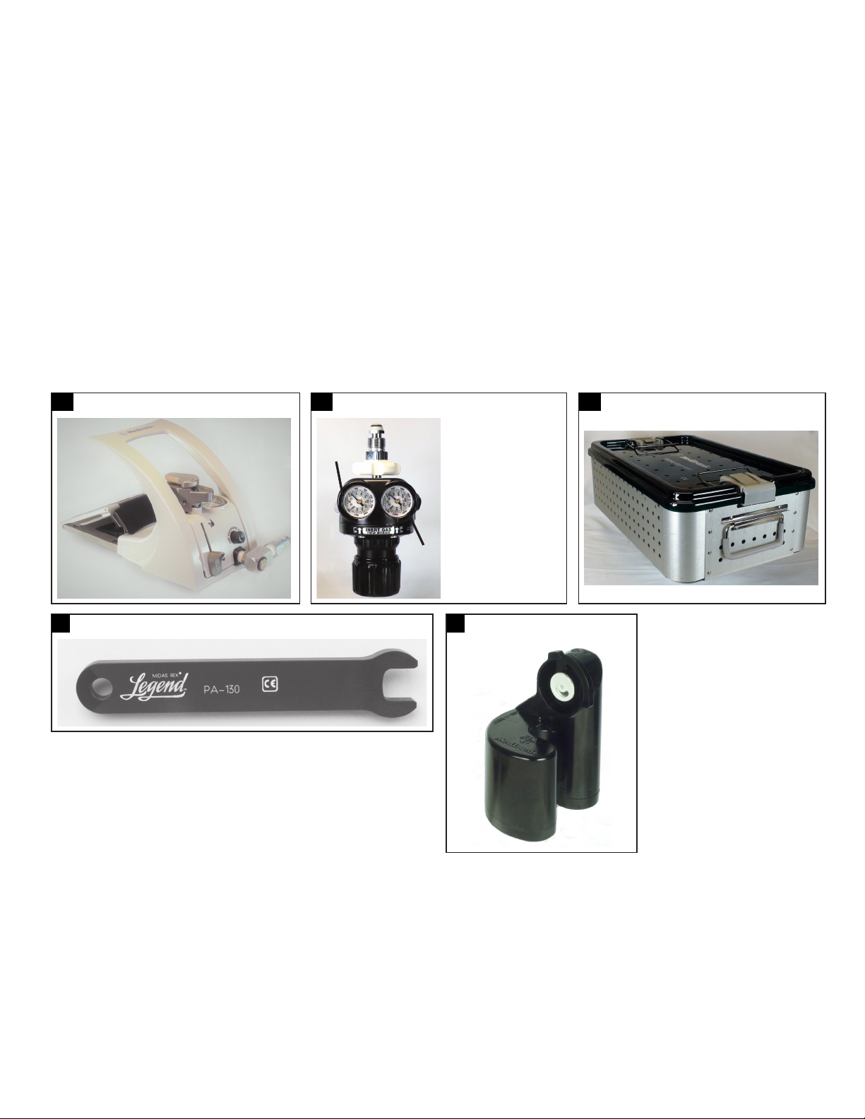
Legend pneumatic control unit
The Legend pneumatic control unit (Figure 2-1) controls speed of Legend Gold and Platinum motors with a variable speed foot pedal, provides nger/foot control for
operation of the Gold Touch Motor, provides a port for Legend motors and a port for TRITON Power Surgical Instrument System. N2 DISS pressure hose is 20’ long. A
longer Medtronic Midas Rex N2 DISS pressure hose is available and may be changed on-site.
Note: Legend pneumatic control unit is provided with a certied Supply Pressure gauge.
Legend pneumatic control unit has a handle (Figure 2-2) for ease of re-positioning unit while on oor or for carrying the unit. A hole is provided in the base for hanging
the unit on a wall hook. Port plugs are attached to prevent debris ingress when a port is not in use.
Caution: Legend pneumatic control unit and pressure hose should not be sterilized.
Warning: Refer to Warnings section Legend pneumatic control unit warnings.
Regulator
The Legend Regulator (Figure 2-3) controls the delivery pressure of compressed gas to the Legend pneumatic control unit. The pressure gauges indicate cylinder
pressure (right gauge) and delivery pressure (left gauge).
Note: Outlet pressure gauge accurate to +/- 12 psi.
Regulator hose
Connects the gas source to the pneumatic control unit to deliver compressed gas.
Legend instrument case
The instrument case (Figure 2-4) is used to organize equipment and to secure instruments during sterilization and transport.
Motor wrench
Used to align arrows on motor collet flats prior to installation of a Legend attachment (Figure 2-5).
Lubricant/diuser cartridge (PA100-A)
Provides lubrication to Legend motors, diuses spent air from motor, and lters oil from exhausted air.
Note: Each Legend Motor has a lubricant/diuser housing (Figure 2-6) at the end of the motor hose. Legend motors and associated hoses do not contain latex.
The Legend Gold, Gold Touch, Platinum lubricant/diuser cartridge (PA100-A) is not interchangeable with the MR7 lubricant/diuser cartridge (PA700). Ensure you
select the appropriate lubricant/diuser cartridge for the motor.
2-1
2-4
Legend pneumatic control unit Legend pneumatic control unit handle Regulator
2-2
2-3
1
2
Instrument case Motor wrench Lubricant/diuser
2-5
2-6
1. Delivery
pressure
gauge
2. Cylinder
pressure
gauge
5
Midas Rex™ Legend™ Pneumatic High-Speed System
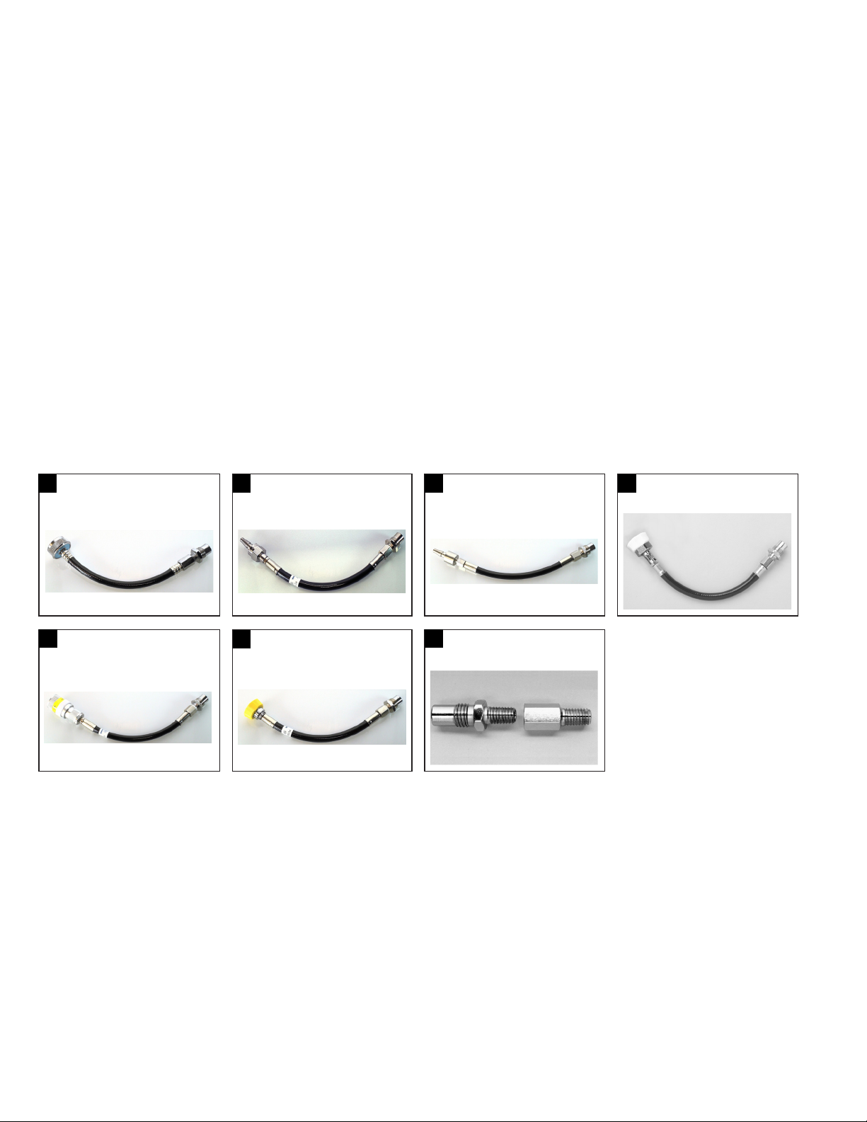
Adapters
N2 DISS to surgical tool air male SIS adapter gas source (Australia/New Zealand only)
The N2 DISS to surgical tool air male SIS adapter gas source (Figure 3-1) allows for the regulator hose to connect to AUS-SIS wall ttings for surgical tool air. The
functioning of the N2 DISS to surgical tool air male SIS adapter gas source is intended for use in Australia and New Zealand only.
N2 DISS to male Schrader adapter
Allows for the Pneumatic Control Unit’s N2 DISS pressure hose connection to be attached to a Female Schrader in-house gas connection (Figure 3-2).
An N2 DISS to Female Schrader Adapter is also available for connection of the Pneumatic Control Unit’s N2 DISS pressure hose to a Male Schrader in-house gas
connection.
N2 DISS to male Schrader adapter (UK)
The N2 DISS to male Schrader adapter (Figure 3-3) allows for the pneumatic control unit’s N2 DISS pressure hose connection to be attached to a female Schrader (UK)
in-house gas connection. This adapter is for use in the UK only.
N2 DISS to air DISS adapter
Allows for the Pneumatic Control Unit’s N2 DISS pressure hose connection to be attached to an Air DISS in-house gas connection (Figure 3-4).
N2 DISS to female Schrader adapter
The N2 DISS to female Schrader adapter (Figure 3-5) allows for the pneumatic control unit’s N2 DISS pressure hose connection to be attached to a male Schrader inhouse gas connection.
N2 DISS to surgical tool air male SIS adapter
The N2 DISS to surgical tool air male SIS adapter (Figure 3-6) allows for the pneumatic control unit’s N2 DISS pressure hose connection to be attached to an AUS-SIS
surgical tool air in-house gas connection.
N2 DISS to WF4 adapter
Allows for the Pneumatic Control Unit’s N2 DISS pressure hose connection to be attached to a Midas Rex Safety Valve Regulator previously used for Midas Rex Classic
or Midas Rex III Motors (Figure 3-7). The in-line oiler must be removed from the Safety Valve Regulator.
3-1
N2 DISS to surgical tool air
male SIS adapter gas source
3-5
N2 DISS to female
Schrader adapter
3-2
3-6
N2 DISS to male
Schrader adapter
N2 DISS to surgical tool air
male SIS adapter
3-3
3-7
N2 DISS to male
Schrader adapter (UK)
N2 DISS to WF4 adapter
3-4
N2 DISS to air DISS adapter
Attachments
Provides support and stability to the rotating dissecting tool.
Legend motor attachments are available in various designs to facilitate a variety of surgical procedures. Attachments vary in length, diameter, and overall design. They
are marked and color-coded to correspond with their associated dissecting tools.
Warning: Refer to Warnings W16.
Notes:
• Angled and straight attachments with the same length, marking, and color band share the same dissecting tool. Curved and straight telescoping tubes with the same
length, marking, and color band share the same dissecting tool.
Example: The AS14/14-AM straight and AA14/14-AM angled attachments are 14 cm long and have a green color band. All dissecting tools with the prex14
(Example:14MH30) may be used in either the straight or angled attachment.
• Color band on attachment is for visual reference. Match the nomenclature and color code on the attachment with that on the dissecting tool packaging.
Dissecting tools
Legend dissecting tools’ intended use is for cutting bone and biomaterials. Legend dissecting tools are provided as sterile.
Warnings: Refer to Warnings W6, W69, and W70.
6

Midas Rex™ Legend™ Pneumatic High-Speed System
Legend power source requirements
Table 1: Power source requirements
Motors Required operating
Legend Gold
Legend Gold Touch
Legend Platinum
Caution: Do not run a Legend motor at an operating pressure below or above the required operating pressure range. Operating pressure below 80 psi (5.5 bar) may
not provide proper lubrication to the motor. Operating pressure above 120 psi (8.3 bar) may damage or reduce the life of the motor.
(dynamic) pressure
80 – 120 psi 100 psi 12 cubic feet/min
5.5 – 8.3 bar 6.9 bar 340 liters/min
80 – 120 psi 100 psi 12 cubic feet/min
5.5 – 8.3 bar 6.9 bar 340 liters/min
80 – 120 psi 100 psi 12 cubic feet/min
5.5 – 8.3 bar 6.9 bar 340 liters/min
Nominal operating
(dynamic) pressure
Approximate ow rate
required
Gas type
Nitrogen or dry-ltered
compressed air
Nitrogen or dry-ltered
compressed air
Nitrogen or dry-ltered
compressed air
Legend pneumatic connections
Warning: Refer to Warnings W73.
Caution: If you are using the Midas Rex Safety Valve Regulator instead of the Legend Regulator, you must replace the in-line oiler with the DISS/WF4 adapter before use.
4
Pneumatic adapter diagram: Gas connection options
1. Regulator hose (N2 DISS) 6. N2 DISS to male Schrader adapter gas source
2. N2 DISS to male Schrader adapter - UK gas source 7. Gas source (N2 DISS)
3. N2 DISS to female Schrader adapter gas source 8. Regulator
4. N2 DISS to surgical tool air male SIS adapter gas source (Australia/New Zealand only) 9. DISS/WF4 adapter
5. N2 DISS to air DISS adapter gas source 10. Regulator (Old Style)
Operating (dynamic) pressure may be checked diagnostically at the Legend or MR7 pneumatic control unit while the motor is running. Operating pressure will
decrease slightly from the non-running (static) pressure setting when the motor is activated. Adjust operating pressure as needed at the compressed gas source until
supply pressure gauge on Legend or MR7 pneumatic control unit reads within a range of 80 – 120 psi (5.5 –8.3 bar), as required.
To ensure optimal motor performance, set nominal operating pressure to 100 psi (6.9 bar). If the surgeon requests additional power during a procedure, compressed
gas source may be turned up to an operating pressure of 120 psi (8.3 bar). To decrease pressure, turn down the in-house compressed gas source or loosen the
pressure handle on the regulator. Push down on the pressure relief at the pneumatic control unit to exhaust excess pressure.
7
Midas Rex™ Legend™ Pneumatic High-Speed System
Legend pneumatic motor technical specications
Table 2. Legend pneumatic motor technical specications
Product Weight (gm)
Legend Gold 143 14.2 1.8
Legend Gold Touch 167 15.5 1.8
Lengend Platinum 100 12.3 1.6
Length (cm) Diameter (cm)
Size
Legend system assembly
Installing the lubricant/diuser cartridge (PA100-A) and connecting the Legend motor to thecontrol unit
Warnings: Refer to Warnings W77 and W78.
1. Set Legend System non-running (static) pressure between 80–120 psi (5.5–8.3 bar) at compressed gas source. Operating (dynamic) pressure may be adjusted as
needed when the motor has an attachment and dissecting tool installed and is running.
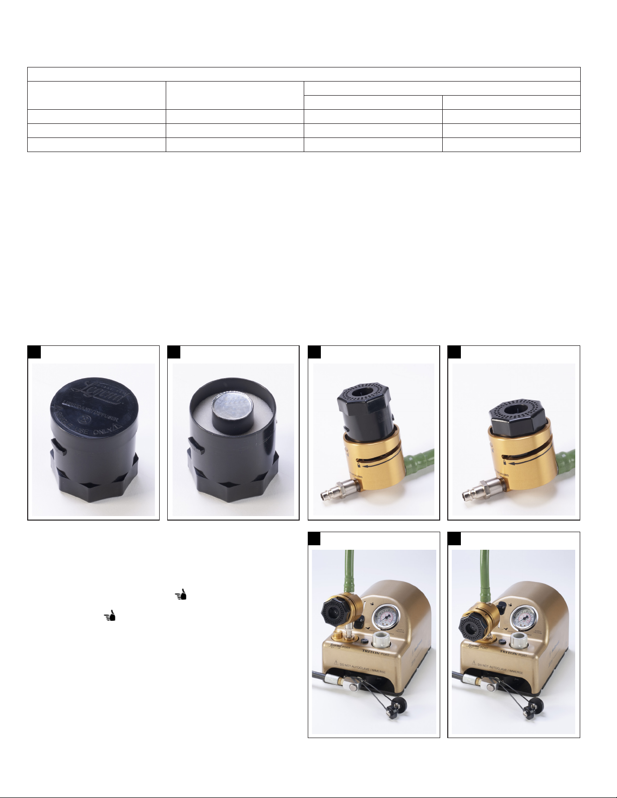
2. a. Remove cover from lubricant/diuser (Figure 5-1).
b. Do not remove inner foil seal of lubricant/diuser (Figure 5-2).
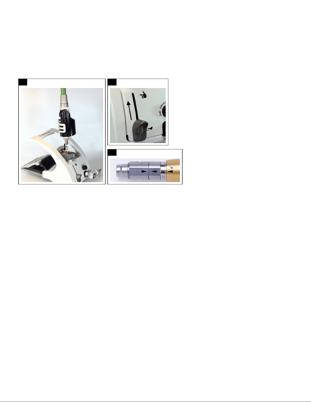
3. Insert lubricant/diuser into lubricant/diuser housing located at base of motor hose (Figure 5-3).
4. Rotate lubricant/diuser from the unlocked position to the locked position (Figure 5-4). It will come to a complete stop with a tactile click when it is fully seated
and locked into the housing.
Notes:
• The lubrication rate is pre-set by the factory and, therefore, should not be altered.
• Cartridges should not be left under pressure for more than 4 hours. If this occurs, an audible air leak may be heard from the diuser housing. If the cartridge has
been pressurized for longer than 4 hours, it should be replaced.
5-1
Lubricant/diuser cover Inner foil (Do not remove) Insert lubricant/diuser Rotate lubricant/diuser
5. Connect the Legend motor oiler housing at the end of the hose to the
Legend port on the Legend pneumatic control unit (Figure 5-5).
Warning: Refer to Warnings W14 and W19.
Notes:
• If using the Legend Gold Touch, slide the nger/foot control on the
Legend pneumatic control unit to the “ ” position (Figure 5-6).
• This will automatically depress and lock the foot pedal. The control will
not lock into the “ ” position unless the motor is connected into the
Legend port.
• If using the TRITON Power Surgical Instrumentation System in conjunction
with the Legend motor, connect the TRITON hose into the TRITON port on
the Legend pneumatic control unit.
5-2
5-3
5-5
Connect the motor hose Lock the nger/foot control
5-4
5-6
8

Midas Rex™ Legend™ Pneumatic High-Speed System
Legend pneumatic control unit activation
Warning: Refer to Warnings W74.
To activate the Legend Gold or Platinum Motors
1. Install and lock an attachment onto the motor as described under section Legend Gold, Legend Gold Touch, and Legend Platinum attachment assembly
and disassembly.
2. Depress the foot pedal on the Pneumatic Control Unit (Figure 6-1). Allow motor to run for approximately 30 seconds. An increase in speed may be noticed as
initial lubrication reaches the motor.
a. For the Legend Gold Touch, be certain the nger/foot control on the Legend pneumatic control unit is locked in the “ ” position.
b. With the Safety Slide in the “ ” position, install and lock an attachment and dissecting tool as described under section Legend Gold, Legend Gold Touch,
and Legend Platinum attachment assembly and disassembly (Figure 6-2).
c. Lift the Finger Control and pull the Safety Slide to the “ | ” position. Depressing the Finger Control will now activate the motor. Allow motor to run for
approximately 30 seconds. An increase in speed may be noticed as lubrication is provided to the motor (Fig. 6-3).
Note: When using longer attachments with the Legend Gold Touch, the extension lever on the Finger Control may be extended to provide better digital control (Figure 6-4).
3. Operating (dynamic) pressure may be checked diagnostically at the Legend pneumatic control unit while the motor is running. Operating pressure will decrease
slightly from the non-running (static) pressure setting when the motor is activated. Adjust operating pressure as needed at the compressed gas source until supply
pressure gauge on Legend pneumatic control unit reads within a range of 80 – 120 psi (5.5 – 8.3 bar) as required.
To ensure optimal motor performance, set nominal operating pressure to 100 psi (6.9 bar).
If the surgeon requests additional power during a procedure, compressed gas source may be adjusted to an operating pressure of 120 psi (8.3 bar).
To decrease pressure, turn down the in-house compressed gas source or loosen the pressure handle on the regulator. Push down on the pressure relief at the
pneumatic control unit to exhaust excess pressure in the hoses. Then re-adjust pressure as needed.
6-1
Depress the foot pedal Install and
6-2
lock attachment
6-3
Allow motor
to run
6-4
Extend the
nger control lever
9
Midas Rex™ Legend™ Pneumatic High-Speed System
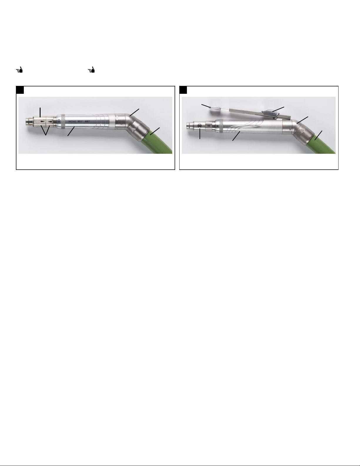
Midas Rex MR7 system motors
MR7
High speed, high torque pneumatic motor (Figure 7-1) used to dissect bone and biomaterials.
MR7 Touch
High speed, high torque pneumatic motor (Figure 7-2) with a variable speed nger control. This motor is used to dissect bone and biomaterials.
Instruction manual will use the “ ” symbol to indicate information on MR7 Touch.
Warning: Refer to Warnings W1.
7-1
1. Collet
2. Collet ats
1
2 3
MR7 motor MR7 Touch motor
4
7-2
1
5
3
3. Motor case
4. Safety slide
3. Motor case
4. Swivel
2
5. Hose 1. Finger control lever
2. Collet
4
5
6
5. Swivel
6. Hose
10
Midas Rex™ Legend™ Pneumatic High-Speed System
MR7 accessories
MR7 pneumatic control unit
The pneumatic control unit (Figure 8-1) provides variable speed motor control through a foot pedal. It also allows the user to switch between nger and foot control
of the motor (if applicable).
Regulator
The Legend Regulator (Figure 8-2) controls the delivery pressure of compressed gas to the Legend pneumatic control unit. The pressure gauges indicate cylinder
pressure (right gauge) and delivery pressure (left gauge).
Note: Outlet pressure gauge accurate to +/- 12 psi.
Regulator hose
Connects the gas source to the pneumatic control unit to deliver compressed gas.
MR7 instrument case
The instrument case (Figure 8-3) is used to organize equipment and to secure instruments during sterilization and transport.
Motor wrench
Used to align arrows on motor collet flats prior to installation of a Legend attachment (Figure 8-4).
Lubricant/diuser cartridge (PA700)
The lubricant/diuser cartridge (Figure 8-5) provides lubrication to the motor and lters oil from exhausted air.
Caution: The Legend lubricant/diuser cartridge and the MR7 lubricant/diuser cartridge are not interchangeable.
8-1
8-4
MR7 pneumatic control unit Regulator MR7 instrument case (PA700)
8-2
1
1. Delivery pressure
gauge
2. Cylinder pressure
gauge
8-3
2
Motor wrench Lubricant/diuser cartridge
8-5
11

Midas Rex™ Legend™ Pneumatic High-Speed System
Adapters
N2 DISS to surgical tool air male SIS adapter gas source (Australia/New Zealand only)
The N2 DISS to surgical tool air male SIS adapter gas source (Figure 9-1) allows for the regulator hose to connect to AUS-SIS wall ttings for surgical tool air. The
functioning of the N2 DISS to surgical tool air male SIS adapter gas source is intended for use in Australia and New Zealand only.
N2 DISS to male Schrader adapter
Allows for the Pneumatic Control Unit’s N2 DISS pressure hose connection to be attached to a Female Schrader in-house gas connection (Figure 9-2).
An N2 DISS to Female Schrader Adapter is also available for connection of the Pneumatic Control Unit’s N2 DISS pressure hose to a Male Schrader in-house gas connection.
N2 DISS to male Schrader adapter (UK)
The N2 DISS to male Schrader adapter (Figure 3-3) allows for the pneumatic control unit’s N2 DISS pressure hose connection to be attached to a female Schrader (UK)
in-house gas connection. This adapter is for use in the UK only.
N2 DISS to air DISS adapter
Allows for the Pneumatic Control Unit’s N2 DISS pressure hose connection to be attached to an Air DISS in-house gas connection (Figure 9-4).
N2 DISS to female Schrader adapter
The N2 DISS to female Schrader adapter (Figure 9-5) allows for the pneumatic control unit’s N2 DISS pressure hose connection to be attached to a male Schrader inhouse gas connection.
N2 DISS to surgical tool air male SIS adapter
The N2 DISS to surgical tool air male SIS adapter (Figure 9-6) allows for the pneumatic control unit’s N2 DISS pressure hose connection to be attached to an AUS-SIS
surgical tool air in-house gas connection.
N2 DISS to WF4 adapter
Allows for the Pneumatic Control Unit’s N2 DISS pressure hose connection to be attached to a Midas Rex Safety Valve Regulator previously used for Midas Rex Classic
or Midas Rex III Motors (Figure 9-7). The in-line oiler must be removed from the Safety Valve Regulator.
TRITON pneumatic adapter
The TRITON adapter (Figure 9-8) allows the TRITON handpiece to be driven by the MR7 pneumatic control unit. It functions much the same way as the TRITON port on
the Legend pneumatic control unit, except that it is connected between the control unit and the gas source, rather than being integrated into the control unit.
9-1
N2 DISS to surgical tool air
male SIS adapter gas source
9-5
N2 DISS to female
Schrader adapter
9-2
9-6
N2 DISS to male
Schrader adapter
N2 DISS to surgical tool air
male SIS adapter
9-3
9-7
N2 DISS to male
Schrader adapter (UK)
N2 DISS to WF4 adapter TRITON pneumatic adapter
9-4
N2 DISS to air DISS adapter
9-8
Attachments
Provides support and stability to the rotating dissecting tool.
Legend motor attachments are available in various designs to facilitate a variety of surgical procedures. Attachments vary in length, diameter, and overall design. They
are marked and color-coded to correspond with their associated dissecting tools.
Warning: Refer to Warnings W16.
Notes:
• Angled and straight attachments with the same length, marking and color band share the same dissecting tool. Curved and straight telescoping tubes with
the same length, marking and color band share the same dissecting tool. Example: The AS14/14-AM straight and AS14/14-AM angled attachments are 14
cm long and have a green color band. All dissecting tools with the prex 14 (14MH30) may be used in either the straight or angled attachment.
• Color band on attachment is for visual reference. Match the nomenclature and color code on the attachment with that on the dissecting tool packaging.
Dissecting tools
Legend Dissecting Tools’ intended use is for cutting bone and biomaterials. Legend Dissecting Tools are provided assterile.
Warnings: Refer to Warnings W6, W69, and W70.
12

Midas Rex™ Legend™ Pneumatic High-Speed System
4
MR7 power source requirements
Table 3: Power source requirements
Motors Required Operating
MR7
MR7 Touch
Caution: Do not run the motor at an operating pressure above or below the required operating pressure range. Operating pressure below 80 psi (5.5 bar) may not
provide proper lubrication to the motor. Operating pressure above 120 psi (8.3 bar) may damage or reduce the life of the motor.
(Dynamic) Pressure
80 – 120 psi 100 psi 12 cubic feet/min
5.5 – 8.3 bar 6.9 bar 340 liters/min
80 – 120 psi 100 psi 12 cubic feet/min
5.5 – 8.3 bar 6.9 bar 340 liters/min
Nominal Operating
(Dynamic) Pressure
Approximate Flow Rate
Required
Gas Type
Nitrogen or Dry-Filtered
Compressed Air
Nitrogen or Dry-Filtered
Compressed Air
MR7 pneumatic connections
Warning: Refer to Warnings W73.
Caution: If you are using the Midas Rex Safety Valve Regulator instead of the Legend Regulator, you must replace the in-line oiler with the DISS/WF4 adapter before use.
10
Pneumatic adapter diagram: Gas connection options
5
3
6
2
7
1
8
9
10
1. Regulator hose (N2 DISS) 6. N2 DISS to male Schrader adapter gas source
2. N2 DISS to male Schrader adapter - UK gas source 7. Gas source (N2 DISS)
3. N2 DISS to female Schrader adapter gas source 8. Regulator
4. N2 DISS to surgical tool air male SIS adapter gas source (Australia/New Zealand only) 9. DISS/WF4 adapter
5. N2 DISS to air DISS adapter gas source 10. Regulator (Old Style)
Operating (dynamic) pressure may be checked diagnostically at the Legend or MR7 pneumatic control unit while the motor is running. Operating pressure will
decrease slightly from the non-running (static) pressure setting when the motor is activated. Adjust operating pressure as needed at the compressed gas source until
supply pressure gauge on Legend or MR7 pneumatic control unit reads within a range of 80 – 120 psi (5.5 –8.3 bar), as required.
To ensure optimal motor performance, set nominal operating pressure to 100 psi (6.9 bar). If the surgeon requests additional power during a procedure, compressed
gas source may be turned up to an operating pressure of 120 psi (8.3 bar). To decrease pressure, turn down the in-house compressed gas source or loosen the
pressure handle on the regulator. Push down on the pressure relief at the pneumatic control unit to exhaust excess pressure.
13

Midas Rex™ Legend™ Pneumatic High-Speed System
MR7 pneumatic motor technical specications
Table 4. MR7 pneumatic motor technical specications
Product Weight (gm)
MR7 121 14.0 1.8
MR7 Touch 145 15.9 1.8
Length (cm) Diameter (cm)
Size
MR7 system assembly
Installing the lubricant/diuser cartridge (PA700) and connecting the MR7 motor to the control unit
1. Set the non-running (static) pressure to 80–120 psi (5.5–8.3 bar) at the gas source. Operating (dynamic) pressure may be adjusted later.
2. Hold the lubricant/diuser cartridge perpendicular to the housing (Figure 11-1), and press the cartridge’s circular tting onto the housing’s circular receptacle
(Figure11-2), breaking the foil seal.
3. Rotate the cartridge down until it clicks into place.
4. Verify that the locked symbol on the cartridge is lined up with the notch on the housing (Figure 11-3).
Warnings: Refer to Warnings W77 and W78.
Caution: Do not use an MR7 motor without a lubricant/diuser installed.
11-1
Aligning the lubricant/diuser
cartridge with the housing
5. Connect the oiler housing at the end of the hose to the motor port on the top of the pneumatic control unit, by swinging the port cover to the side and pressing
the end of the hose into the port (Figure 11-4).
Warning: Refer to Warnings W75.
Notes:
• If using the MR7 Touch motor, slide the control slide on the pneumatic control unit to the “ ” position (Figure 11-5). This will automatically depress and lock
the foot pedal. The control will not lock into the “ ” position unless the motor hose is connected into the motor port. When the motor hose is removed from
the motor port, the foot pedal will return to normal position.
• If using the TRITON Power Surgical Instrumentation System in conjunction with the MR7 motor, use the optional TRITON adapter to connect the TRITON hose.
Refer to the documentation accompanying the adapter for connection instructions.
• The motor’s exhaust hose may have an oily lm on the external surface from pressure and/or temperature dierentials following sterilization. Wipe the exhaust
hose with a sterile cloth prior to use. If motor continues to have oil on the exhaust hose, return the motor to MPSS for refurbishing.
Warning: Refer to Warnings W22.
Prior to installation of a Legend attachment and dissecting tool, ensure that the arrows on the motor collet ats are aligned (Figure 11-6). If the arrows are not aligned,
use the motor wrench to turn the collet at closest to the motor case until its arrow is aligned with the arrow on the other collet at.
11-2
Pressing the cartridge
onto the housing
11-3
Correctly installed
lubricant/diuser cartridge
14
Midas Rex™ Legend™ Pneumatic High-Speed System
MR7 pneumatic control unit activation
Note: In order to activate the MR7 Touch motor, the safety slide on the nger control switch must be in the “|” position, and the control slide on the foot control must
be in the “On” (nger control) position. The control slide will not lock in the “On” (nger control) position unless a motor is connected to the motor port.
To activate the MR7 or MR7 Touch motors
1. Activate the motor by pressing on the foot control pedal (Figure 11-4) or by pressing on the nger control lever (MR7 Touch motor only).
2. Adjust operating pressure as needed at the compressed gas source until supply pressure gauge on pneumatic control unit reads within a range of 80–120 psi
(5.5–8.3 bar) as required. Operating pressure (with motor running) will decrease slightly from the non-running (static) pressure setting when the motor is activated.
Note: To decrease pressure, turn down the in-house compressed gas source or loosen the pressure handle on the regulator. Push down on the pressure relief at the
pneumatic control unit to exhaust excess pressure in the hoses. Then re-adjust pressure as needed.
11-4
Connecting the motor Finger/foot control slide
11-5
11-6
Aligning the collet at
15

Midas Rex™ Legend™ Pneumatic High-Speed System
Legend Gold, Legend Gold Touch, Legend Platinum, MR7, and MR7 Touch lock
Legend Gold, Legend Gold Touch, Legend Platinum, MR7, and MR7 Touch motors should only be operated when the attachment is in the locked position on the motor.
12-1
Motor will operate Motor will not operate
12-2
Legend Gold Touch and MR7 Touch safety slide
The Legend Gold Touch will operate with the safety slide in the “ | ” position and will not operate with the safety slide in the “ ” position.
12-3
12-5
Legend Gold Touch
motor will operate
MR7 Touch motor will operate MR7 Touch motor will not operate
12-4
12-6
Legend Gold Touch
motor will not operate
In addition, the Legend Gold Touch and the MR7 Touch will not operate if the nger/foot control on the pneumatic control unit is in the “ ” position, unless the
foot pedal is activated also.
Legend Gold Touch motor will not operate. MR7 Touch motor will not operate.
12-7
12-8
16

Midas Rex™ Legend™ Pneumatic High-Speed System
56
Legend Gold, Legend Gold Touch, Legend Platinum, MR7, and MR7 Touch tools and attachments
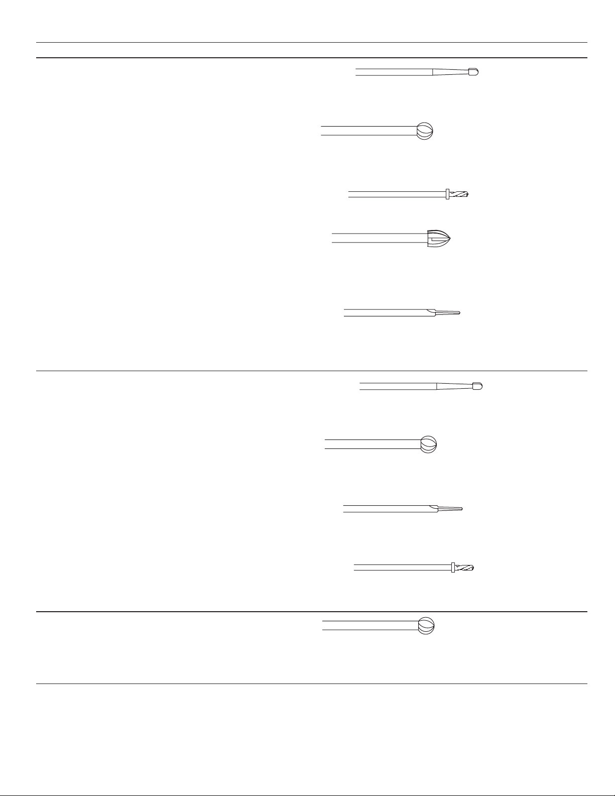
Dissecting tool nomenclature
Warning: Refer to Warnings W6.
Part numbers for dissecting tools follow a standard naming convention (Figure 13). A basic part number consists of ve characters, representing the associated attachment
length, the tool-head shape, and the tool-head diameter. Part numbers can also include a variety of prexes to identify specic attachment types, as well as a variety of
suxes to provide additional information about the dissecting tool. Tools that use a design taken from the Mednext line are designated by an additional “-MN” sux.
13
Dissecting tool nomenclature naming convention
9 M H 3 0
1234
1. Optional prex
2. Attachment length, x centimeters
(Ex. 9 = 9 cm)
3. Tool head shape, xx form/function
(Ex. MH = Match Head)
Tool number prexes Tool number suxes
Note: A single part number will use only one prex. Note: More than one sux may be combined in a
Prex Tool attatchments Sux Tool head shape modiers
CB
F
SD
SP
T
TN
Tool head shape (form/function) Sux Tool head cutting modiers Sux Tool length modiers
AC
BA
CY
HM
HS
MC
MH
OV
RT
TA
TD
Curved Burr
Footed attachments
Spinal with Distal bend
Spinal with Proximal bend
Telescoping tube
Trans-Nasal
Acorn
Ball
Cylinder
Hole Maker
Hole Saw
Metal Cutting
Match Head
Oval
Reverse Taper
Tapered or side cutter
Twist Drill
4. Tool head diameter, x.x millimeters
(Ex. 30 = 3.0 mm)
5. Optional sux
6. Optional “-MN” sux
single part number.
B
BR
M
PR
S
T
C
D
DC
DF
DX
DXF
F
-MN
X
XF
Ball end
Barrel
2-Flute Match style
Pear shaped
Spiral utes
3-Flute or SymmeTRI
Carbide
Diamond
Diamond Coarse
Diamond Fine
Diamond Extra Coarse
Diamond Extra Fine
Fine
MedNext style
Coarse
Extra Fine
L
SH
Pxx
Mxx
Long
Short
Plus ‘xx’ mm
(for example, P15 = Plus 15mm)
Minus ‘xx’ mm
17

Midas Rex™ Legend™ Pneumatic High-Speed System
General guidelines for attachments and tool applications
These are general guidelines for dissecting tool applications and are not an all-inclusive listing.
Surgical application Commonly used attachments Commonly used dissecting tools
Spine 8-B
9-M
14-AM straight or angled
15-A straight or angled
Match head
Elongated spherical design allows controlled, delicate dissection. For entry
hole, nerve decompression, osteophyte removal, sinus dissection, etcetera.
Ball
Helical cutting utes dissect bone or cement eectively from a wide
variety of approach angles. For debridement, decortication, sinus
dissection, etcetera.
Oval
Helical cutting utes and curved design blend acorn and ball styles to vary
dissection eciency with approach angle. For decortication, laminotomy,
entry hole, nerve decompression, osteophyte removal, etcetera.
Hole maker and hole saw
Matched sets of hole makers and hole saws are ecient and eective
for interbody fusion.
Cylinder
Eective bone sculpting and planing. For graft shaping, debridement,
corpectomy, decortication, interbody fusion, fusion takedown, etcetera.
Acorn
Curved design varies dissection eciency with varied approach
angles. For entry hole, laminotomy, bone shaping, debridement,
corpectomy, decortication, fusion takedown, etcetera.
Telescoping Match head
Elongated spherical design allows controlled, delicate dissection. For
entry hole, nerve decompression, osteophyte removal, sinus dissection,
etcetera.
Spine Footed Tapered
Slender design for precise dissection with minimal bone loss. For
transection, osteotomy, graft harvesting, bone shaping, entry hole,
suture hole, midface advancement, etcetera.
Reverse tapered
Semi-trapezoidal shape with helical cutting utes and a smooth
cutting tip designed for ecient bone sculpting and planing. For
graft shaping, debridement, and decortication.
18
Midas Rex™ Legend™ Pneumatic High-Speed System
Surgical application Commonly used attachments Commonly used dissecting tools
Neurosurgical–cranial 7-6ST straight or angled
8-B
9-M
10-9ST straight or angled
14-AM straight or angled
15-A straight or angled
Footed Tapered
Match head
Elongated spherical design allows controlled, delicate dissection.
For entry hole, nerve decompression, osteophyte removal, sinus
dissection, etcetera.
Ball
Helical cutting utes dissect bone or cement eectively from a wide
variety of approach angles. For debridement, decortication, sinus
dissection, etcetera.
Twist drill
Helical design with stop produces a hole with a precise depth. Ideal for
plating.
Acorn
Curved design varies dissection eciency with varied approach
angles. For entry hole, laminotomy, bone shaping, debridement,
corpectomy, decortication, fusion takedown, etcetera.
Slender design for precise dissection with minimal bone loss. For
transection, osteotomy, graft harvesting, bone shaping, entry hole,
suture hole, midface advancement, etcetera.
General surgery
and plastic surgery
(craniofacial/
maxillofacial/
sternotomy)
Ear, nose, and
throat (otology,
neurootology)
7-6ST straight or angled
8-B
9-M
10-9ST straight or angled
14-AM straight or angled
7-6ST straight or angled
10-9ST straight or angled
Match head
Elongated spherical design allows controlled, delicate dissection.
For entry hole, nerve decompression, osteophyte removal, sinus
dissection, etcetera.
Ball
Helical cutting utes dissect bone or cement eectively from a wide
variety of approach angles. For debridement, decortication, sinus
dissection, etcetera.
Tapered
Slender design for precise dissection with minimal bone loss. For
transection, osteotomy, graft harvesting, bone shaping, entry hole,
suture hole, midface advancement, etcetera.
Twist drill
Helical design with stop produces a hole with a precise depth. Ideal
for plating.
Ball
Helical cutting utes dissect bone or cement eectively from a wide
variety of approach angles. For debridement, decortication, sinus
dissection, etcetera.
19

Midas Rex™ Legend™ Pneumatic High-Speed System
Surgical application Commonly used attachments Commonly used dissecting tools
Orthopaedics 8-B
9-M
14-AM straight or angled
21-TU
26-R
Footed
Telescoping
Biometals/bioceramics/
MC Metal cutter
biomaterials
Ball
Helical cutting utes dissect bone or cement eectively from a wide
variety of approach angles. For debridement, decortication, sinus
dissection, etcetera.
Tapered
Slender design for precise dissection with minimal bone loss. For
transection, osteotomy, graft harvesting, bone shaping, entry hole,
suture hole, midface advancement, etcetera.
Acorn
Curved design varies dissection eciency with varied approach
angles. For entry hole, laminotomy, bone shaping, debridement,
corpectomy, decortication, fusion takedown, etcetera.
Cylinder
Eective bone sculpting and planing. For graft shaping, debridement,
corpectomy, decortication, interbody fusion, fusion takedown, etcetera.
Cutting utes or diamond wheel design remove metals, ceramics and
other biomaterials eectively from a variety of approach angles. For
cutting rods, pins, plates, implants, screws, etcetera.
20

Midas Rex™ Legend™ Pneumatic High-Speed System
Table 5: Glossary
Surgical procedures Tool head designs
LM Lumbar Microdiscectomy PH Pilot Hole MH
Lumbar Stenosis
LSD
Decompression
Posterior Lumbar
Interbody Fusion (PLIF)
Transforaminal Lumbar
Interbody Fusion (TLIF)
LIF
Anterior Lumbar Interbody
Fusion (ALIF)
Direct Lateral Interbody
Fusion (DLIF)
FT Fusion Takedown MI Minimally Invasive procedure T Fluted dissecting tool, cutting utes to allow faster, and ecient bone removal.
LT Laminotomy TA
FRT Foramenotomy MC Metal Cutting dissecting tool to facilitate the cutting and shaping of metal.
Surgical application - Spine
Incision/cutting, removal, drilling, and sawing of soft and hard tissue,
bone, and biomaterials.
LM LSD LIF FT LT FRT PH ND OR DB DC CT MI
ND Nerve Decompression BA
OR Osteophyte Removal AC
DB Debridement CY Cylinder dissecting tool eective in bone sculpturing and planning.
DC Decortication HM/S
CT Corpectomy OV
Table 6: General guidelines for attachment and tool applications
Commonly used attachments
Match Head dissecting tool with an elongated spherical design allows
controlled, delicate dissection.
Ball dissecting tool, cutting utes to dissect bone or cement eectively
from a wide variety of approach angles.
Acorn dissecting tool, curved design varies dissection eciency with
varied approach angles and eective in bone shaping.
Hole Maker/Hole Saw dissecting tool, matched sets of hole makers and
hole saws are ecient and eective.
Oval dissecting tool with helical cutting utes and curved design blend
acorn and ball styles to vary dissection eciency with approach angle.
Tapered dissecting tool with slender design for precise dissection with
minimal bone loss.
Tools
MH BA AC CY HM/S OV T TA MC
X X X X X X X X X X X X X
X X X X X X X X X X X X X
X X X X X X X X X X X X X
X X X X X X X X X X X X X
X X X X X X X X X X X X
X X X X X X X X X X X X X
X X X X X X X X X X X X
Straight
Angled
Base Tube
Straight Straight Angled Curved
Angled
Footed
Curved burs
Contra angle
X X X X X X X X
X X X X X X X X
X X X X X
X X X X X
X
X X X
X X
X X X X X X X X X X X X X
ASMC
X
21
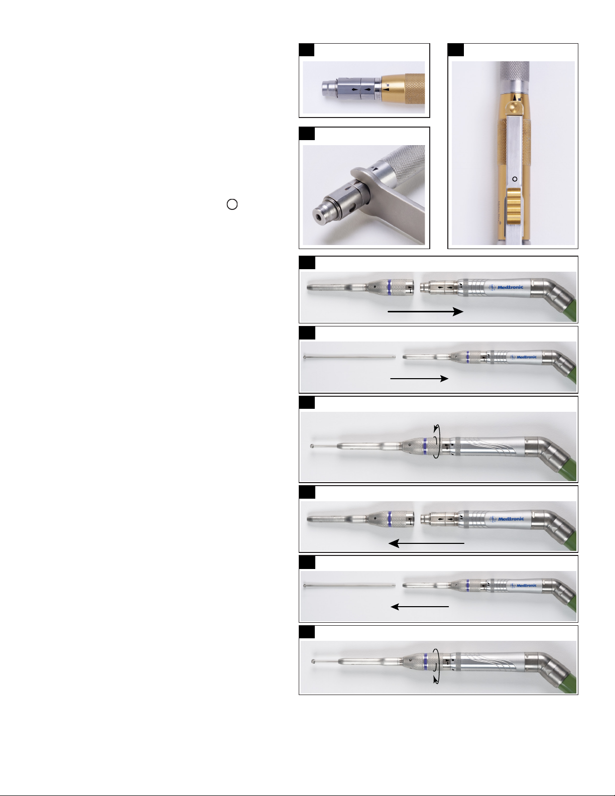
Midas Rex™ Legend™ Pneumatic High-Speed System
Attachment assembly and disassembly
Warnings: W6, W24, W33, W34, W52, and W54 apply to all Legend attachments.
Prior to installation of a Legend Attachment and Dissecting Tool onto a
Legend Motor, ensure that arrows on the motor collet ats are in proper
alignment (Figure 14-1). If the arrows are not aligned, use the Legend motor
wrench (Figure 14-2) to turn the rotational collet (closest to the motor case)
until its arrow is aligned with the arrow on the stationary collet (farthest
away from the motor case).
Notes:
• A Legend Attachment will not seat onto a Legend Motor if the arrows on
the collet ats are not in alignment.
• Do not use any other components except for the Legend Motor Wrench
to align arrows on motor collet.
• Before installation of attachment and dissecting tool on the Legend
Gold Touch Motor, ensure that the safety slide is in the “ ” position
(Figure14-3).
Straight attachment
Note: An attachment will not seat on the motor if the arrows on the collet
ats are not in alignment.
Assembly:
1. Slide a straight attachment over the motor collet aligning the
triangular arrows on the attachment and the motor case (Figure 15-1).
An audible click, heard and perceptible by touch, conrms that the
attachment is fully seated.
2. Insert the tool into the attachment with a slight rotational motion
(Figure15-2). An audible click, heard and perceptible by touch, conrms
that the tool is fully seated.
3. Rotate the attachment in the direction indicated by arrow on the
attachment until the attachment alignment mark is directly in line
with the locked symbol (Figure 15-3). You will hear two clicks as the
attachment is rotated.
Note: Only when the second click is heard is the attachment fully
seated and the collet brake fully released.
4. Gently pull on the tool to ensure that it is locked into the motor.
Note: Tool should rotate freely. If not, unlock the attachment, re-seat
the tool, and re-lock the attachment.
14-1
Motor collet alignment Safety slide in the ‘O’ position
14-2
Turn the rotational collet
15-1
15-2
15-3
Straight attachment assembly
Straight attachment assembly
Straight attachment assembly
14-3
Disassembly:
1. Hold the motor in palm of hand. Rotate the attachment to the unlocked
position. In this position, the arrows in the attachment and motor will
line up as in Figure 15-4.
2. Remove the dissecting tool from the attachment and discard the tool
(Figure 15-5).
3. Use thumb and index nger to lift the attachment o of the motor
(Figure 15-6).
22
15-4
15-5
15-6
Straight attachment disassembly
Straight attachment disassembly
Straight attachment disassembly

Midas Rex™ Legend™ Pneumatic High-Speed System
Angled attachment
Warnings: Refer to Warnings W40.
Caution: When using an angled attachment, hold the motor assembly by the attachment so that the attachment does not inadvertently loosen from the motor.
Notes:
• A dissecting tool may be installed and locked in the attachment before the angled attachment is installed onto the motor.
• Angled and straight attachments with the same length, marking, and color band share the same dissecting tools.
Assembly:
1. With the tool lock in the unlocked position, insert a tool into the angled
attachment with a slight rotational motion (Figure 16-1). An audible click,
heard and perceptible by touch, conrms that the tool is fully seated.
2. Rotate the tool lock/unlock sleeve in the direction indicated by arrow
until the tool lock alignment mark is directly in line with the locked
symbol (Figure 16-2).
3. Gently pull on the tool to ensure that it is locked into the motor.
Note: Tool should rotate freely. If not, unlock the attachment, re-seat the
tool, and re-lock the attachment.
4. Slide the angled attachment over the motor collet aligning the triangular
arrows on the attachment and the motor case. An audible click, heard and
perceptible by touch, conrms that the tool is fully seated.
5. Rotate the attachment in the direction indicated by the arrow until
attachment alignment mark is directly in line with the locked symbol. You
will hear two clicks as the attachment is rotated.
Note: Only when the second click is heard is the attachment fully seated
and the collet brake fully released.
6. Verify that both the attachment to motor alignment mark and the tool lock
alignment mark are directly in line with the locked symbols (Figure 16-3).
Disassembly:
1. Rotate the tool lock to the unlocked position to remove the tool from the
attachment.
2. Rotate the attachment to the unlocked position and lift attachment o of
the motor.
Fixed footed attachment
Warning: Refer to Warnings W41.
16-1
16-2
16-3
17-1
Angled attachment assembly
Angled attachment assembly
Angled attachment assembly
Fixed footed attachment assembly
Assembly:
1. Insert a dissecting tool into the motor collet with a slight rotational
motion (Figure 17-1). An audible click, heard and perceptible by touch,
conrms that the attachment is fully seated.
2. Slide the xed footed attachment over the dissecting tool onto the
motor aligning triangular arrows on the attachment and the motor case
(Figure17-2).
3. Pull the xed footed attachment towards the motor and rotate the
attachment to the locked position on the motor case (Figure 17-3).
4. Check to ensure a gap exists between the tip of the tool and the foot
of the attachment. This will prevent damage to the attachment and/or
injury to patient.
Disassembly:
1. To remove the xed footed attachment, hold the motor in the palm of
your hand. Push the sleeve on the xed footed attachment distally while
rotating the attachment to the unlocked position on the motor case and
then release the sleeve.
2. To avoid injury from the dissecting tool, use thumb and index nger to
cautiously and slowly lift the attachment o of the motor and away from
the dissecting tool.
3. Pull the dissecting tool out of the motor collet and discard the tool.
17-2
17-3
Fixed footed attachment assembly
Fixed footed attachment assembly Tool gap
17-4
23

Midas Rex™ Legend™ Pneumatic High-Speed System
Rotating footed attachment
Notes:
• Rotating and xed footed attachments with the same length, marking,
and color band share the same dissecting tools.
• The footed end of the attachment has 360° of unrestricted rotation.
Warning: Refer to Warnings W41.
18-1
Rotating footed attachment assembly
Assembly:
1. Insert a dissecting tool into the motor collet with a slight rotational
motion (Figure 18-1). An audible click, heard and perceptible by touch,
conrms that the attachment is fully seated.
2. Slide the rotating footed attachment over the dissecting tool onto the
motor aligning triangular arrows on the attachment and the motor case
(Figure 18-2).
3. Pull the rotating footed attachment towards the motor and rotate the
attachment to the locked position on the motor case (Figure 18-3).
4. Check to ensure a gap exists between the tip of the tool and the foot
of the attachment. This will prevent damage to the attachment and/or
injury to patient.
Disassembly:
1. Hold the motor in palm of hand. Rotate the attachment to the unlocked
position. In this position, the arrows in the attachment and motor will line up.
2. Use thumb and index nger to lift the attachment o of the motor.
3. Remove the dissecting tool from the motor collet and discard the tool.
Contra-angle attachment AC-16
Assembly:
Note: The static pressure to the motor should be set to 80 psi (5.5 bar).
1. Slide the contra-angle attachment over the motor collet aligning triangular
arrows on the attachment and the motor case.
2. Rotate the attachment to the locked position on the motor case (Figure 19-1).
3. Rotate the attachment head’s lever laterally to the open position and insert a
dissecting tool (Figure 19-2).
4. Align the at in the tool with the corresponding at in the attachment and fully
insert tool into the attachment.
5. Close lever (Figure 19-3) to lock tool in the attachment.
6. Gently pull on the dissecting tool shaft to ensure it is locked in the attachment.
18-2
18-3
Rotating footed attachment assembly
Rotating footed attachment assembly Tool gap
19-1
19-2
Contra-angle attachment AC-16 assembly
Attachment assembly Attachment assembly
19-3
18-4
Disassembly:
1. Rotate the lever on the attachment head laterally to unlock the tool and then
remove the dissecting tool.
2. Discard the dissecting tool.
3. Rotate the AC-16 attachment to the unlocked position and lift the attachment o
of the motor.
24
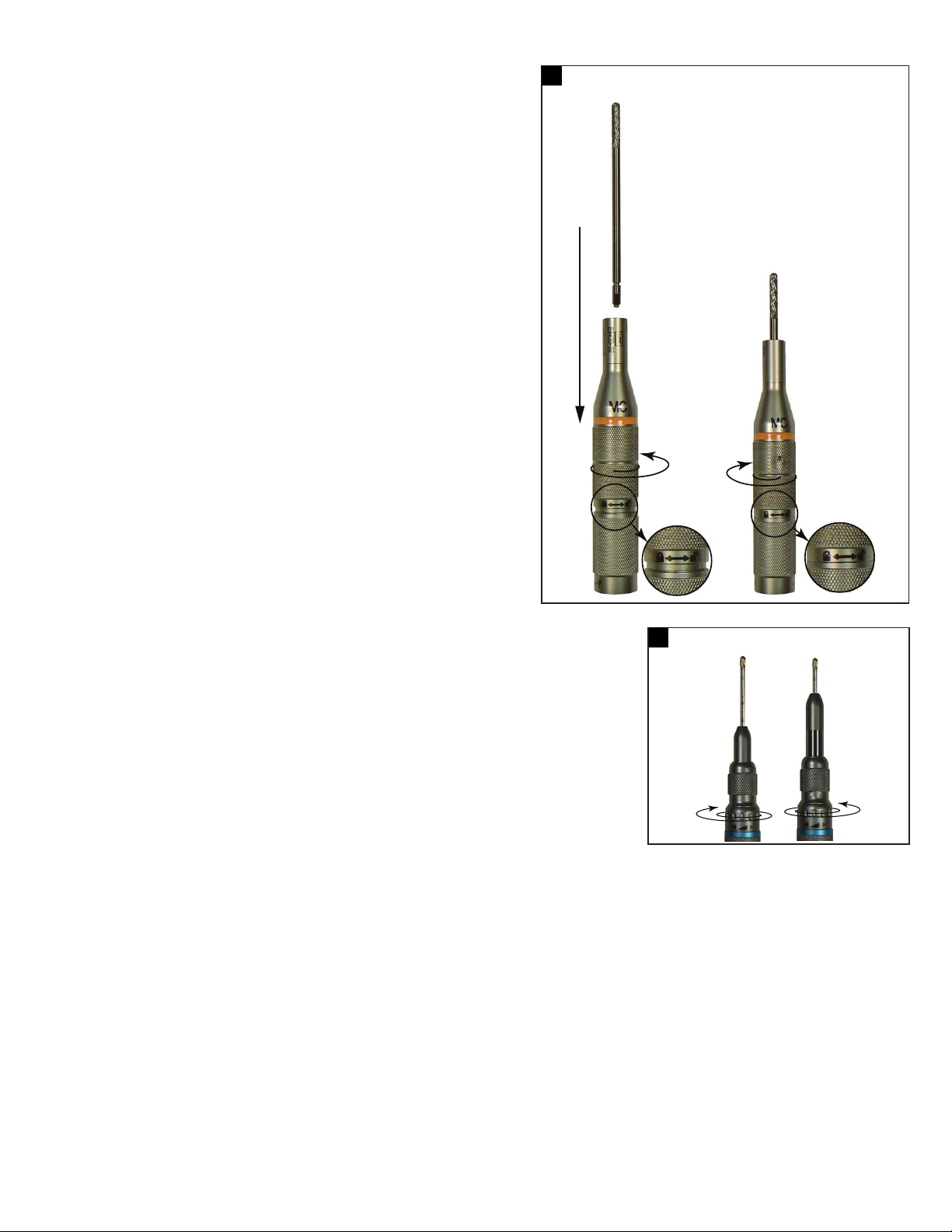
Metal cutting attachment
Warning: Refer to Warnings W61.
Note: The metal cutting attachment uses the tungsten carbide or diamond wheel
dissecting tools. All metal cutting dissecting tools have an “MC” attachment prex in
their nomenclature (for example, MC254 and MC30). Metal cutting dissecting tools
cannot be installed into any other attachment.
Assembly:
1. Slide the metal cutting attachment over the motor collet aligning triangular marks
on the attachment and the motor case. An audible click, heard and perceptible by
touch, conrms that the attachment is fully seated.
2. Rotate the attachment to the locked position on the motor case.
3. Unscrew tool lock sleeve several turns and while holding the attachment upright,
insert a dissecting tool into the attachment.
4. Rotate the dissecting tool until it drops into position and is fully seated (Figure 20).
5. Lock the tool in the attachment by rotating the locking sleeve in the direction
shown on the attachment until the tool is secured.
6. Gently pull on the tool to ensure that it is secured in the attachment.
Disassembly:
1. Unscrew the tool lock with several turns, then withdraw the dissecting tool.
Note: Do not rotate past the point where resistance is felt.
2. Discard tool.
3. Rotate the attachment to the locked position on the motor case and lift
attachment o of the motor.
20
Midas Rex™ Legend™ Pneumatic High-Speed System
Metal cutting attachment
Variable exposure straight and angled attachment
Warning: Refer to Warnings W26.
Note: The variable exposure attachments can be distinguished from standard attachments by the dual color bands
on the attachment. Match the color band on the attachment to the color code on the dissecting tool packaging.
Assembly:
1. Assemble the variable exposure straight attachment using the Straight attachment Assembly instructions
and the variable exposure angled attachments using the Angled attachment Assembly instructions.
2. After assembly, use the tube adjustment ring to adjust the exposure of the dissecting tool (Figure 21).
With the tool pointing away from you, turn the ring to the right to increase the length of the tube, thereby
decreasing the exposure of the tool. Turn the ring to the left to decrease the length of the tube, thereby
increasing the exposure of the tool.
Disassembly:
Remove the variable exposure straight attachment using the Straight attachment Disassembly instructions
and the variable exposure angled attachments using the Angled attachment Disassembly instructions.
21
Variable exposure attachment assembly
25
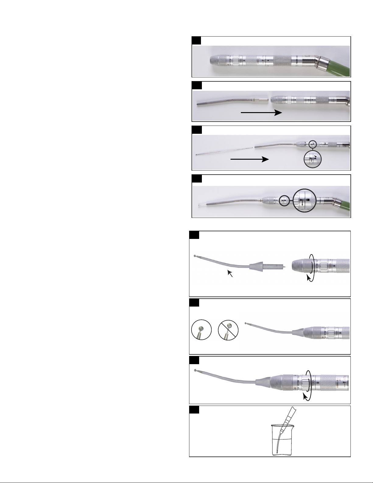
Midas Rex™ Legend™ Pneumatic High-Speed System
Telescoping tube and telescoping tube base attachment – straight (AT10) and angled (AT10A)
Assembly:
1. Assemble the telescoping base attachment straight (AT10) or angled (AT10A) to
the motor using the Straight attachment Assembly instructions (Figure 22-1).
2. Insert the base end of the telescoping tube into the AT10, or AT10A attachment
until the hub is fully seated. To secure the tube, turn the tube locking ring on
the AT10, or AT10A attachment until nger tight (Figure 22-2).
Note: Do not over tighten.
3. Verify that the telescoping tube is secure by gently pulling on the tube.
4. Rotate the tool locking ring to the unlocked position.
5. Insert the tool into the telescoping tube. Apply a slight amount of inward
pressure on the tool (Figure 22-3). An audible click, heard and perceptible by
touch, conrms that the tool is fully seated.
6. Turn the tool locking ring to the locked position (Figure 22-4).
7. Verify that the tool is secured by gently pulling on the tool.
8. To vary the tube position/tool exposure, rotate the tube locking ring toward
the unlocked position, re-position the tube, then rotate the tube locking ring
toward locked position until nger tight.
Note: Do not over tighten.
9. Gently pull on the dissecting tool, then the tube, to ensure they are secure.
Disassembly:
1. Rotate the tube locking ring towards the unlocked position.
2. Rotate the tool locking ring to the unlocked position.
3. Remove the tool and then the telescoping tube from the AT10, or A10A attachment.
4. Discard the tool.
5. Rotate the AT10, or AT10A attachment to the unlocked position on the motor
case and lift the attachment o the motor.
22-1
22-2
22-3
22-4
Telescoping tube attachment assembly
Telescoping tube attachment assembly
Telescoping tube attachment assembly
Telescoping tube attachment assembly
Telescoping curved bur and telescoping base attachment straight (AT10) and angled (AT10A)
Assembly:
1. Assemble the attachment straight (AT10), or angled (AT10A) using the
Straight attachment Assembly instructions.
2. Insert the base end of the curved bur into the AT10, or AT10A attachment
until the hub is fully seated. To lock in place, turn the tube locking ring until
nger tight (Figure 23-1).
Note: Do not over tighten.
3. Verify that the hub is in place by gently pulling on the tool.
4. Seat the tool in the AT10, or AT10A attachment by gently pushing on the bur
(Figure 23-2). An audible click, heard and perceptible by touch, conrms that
the tool is fully seated. Verify tool is seated by checking the bur head
exposure as shown in Figure 23-2.
5. Rotate the tool locking ring until the tool lock alignment mark is directly in
line with the locked symbol (Figure 23-3).
6. Verify that the bur is secured by gently pulling on the bur.
7. Prior to initial use, soak the cooling sleeve by dipping it into a cup of saline or
deionized (DI) water (Figure 23-4).
8. During use, copiously irrigate the cooling sleeve and bur by dribbling saline
or DI water along the entire length of the cooling sleeve.
Disassembly:
1. Rotate the tube locking ring towards the unlocked position.
2. Rotate the tool locking ring to the unlocked position.
3. Remove the curved bur from the AT10, or AT10A attachment.
4. Discard the curved bur.
5. Rotate the AT10, or AT10A attachment to the unlocked position on the
motor case and lift the attachment o the motor.
23-1
Telescoping curved bur and telescoping base
attachment straight (AT10) and angled (AT10A) assembly
1
1. Cooling sleeve
23-2
23-3
23-4
Curved bur cooling
Attachment assembly
Attachment assembly
26
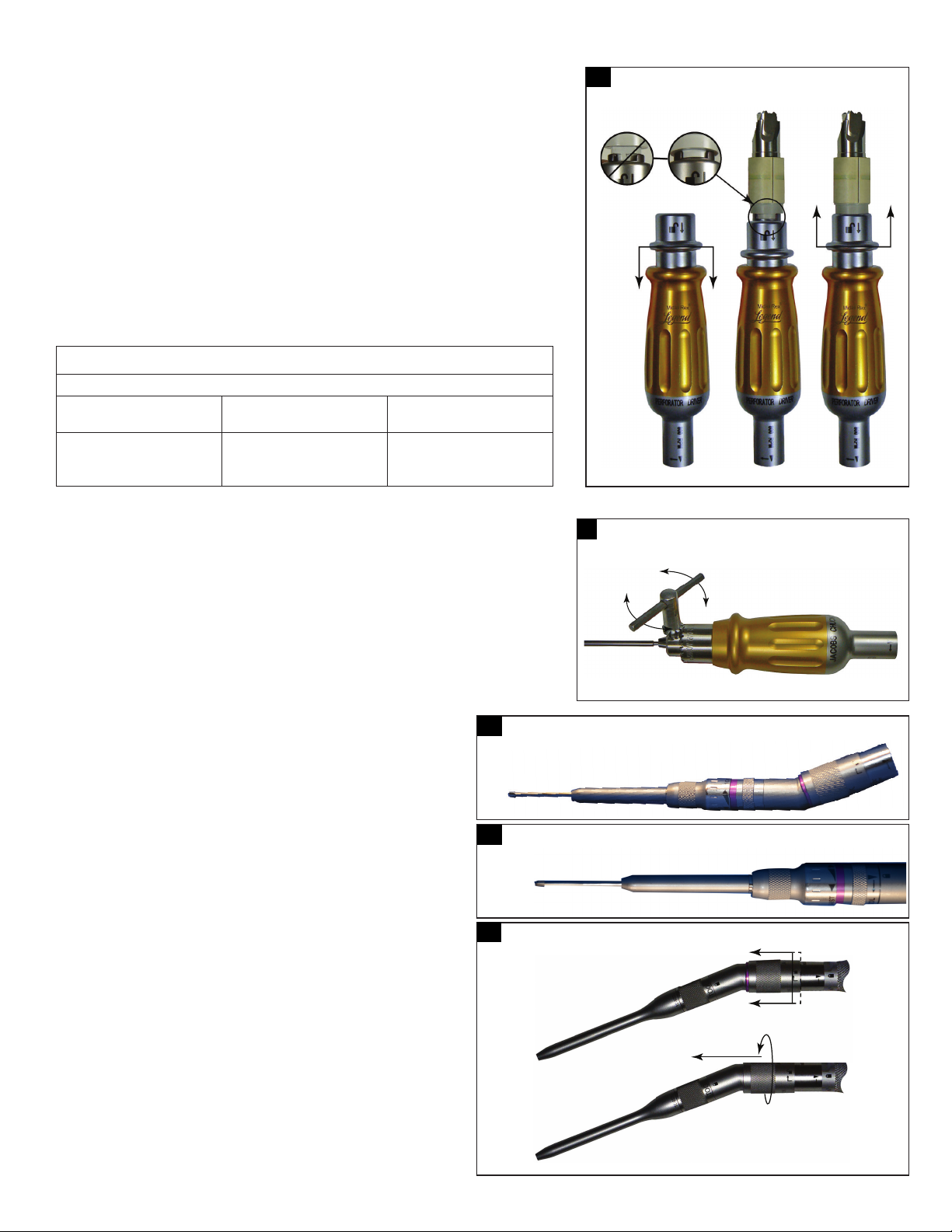
Midas Rex™ Legend™ Pneumatic High-Speed System
Perforator (AD01 & AD03) attachment
Notes:
• A cranial perforator device may be installed in the attachment before the perforator attachment
is installed on the motor.
• Excessive noise from the tool when drilling close to the cochlea or ossicular chain may cause
hearing damage.
• Consult the cranial perforator device labeling for recommended speed specications.
Assembly:
1. Assemble the attachment onto the motor using the Straight attachment Assembly instructions.
2. To install a cranial perforator device with a hudson shank, pull back proximally on the collar of
the perforator attachment. Insert a device and release the collar to its original position (Figure 24).
3. The speeds achievable by the AD01 and AD02 attachments are provided in Table 7.
Disassembly:
1. Pull back proximally on the collar of the perforator attachment and then remove the cranial
perforator device.
2. Rotate the perforator attachment to the unlocked position and lift the attachment o of the motor.
Table 7: Maximum speed of perforator attachments with Legend pneumatic motors
Pneumatic motors
Gas pressure
(dynamic)
80 psi
100 psi
120 psi
AD01 output
speed (maximum)
660 rpm
820 rpm
890 rpm
AD03 output
speed (maximum)
850 rpm
1050 rpm
1140 rpm
Jacobs chuck attachment
Assembly:
1. Assemble the attachment onto the motor using the Straight attachment Assembly instructions.
2. Install the Jacobs chuck key as shown in Figure 25 and rotate it counterclockwise to open the
ridged collar.
3. Insert drill bit and tighten collar by turning the Jacob’s Chuck key clockwise (Figure 25) until the
tool is secure.
Disassembly:
1. Using the Jacobs key, open the collar.
2. Remove and discard the drill bit.
3. Rotate the Jacobs chuck attachment to the unlocked position and lift the attachment o of
the motor.
25
24
Perforator attachment assembly
Jacobs chuck attachment assembly
Angled double lock (DK) attachment
Notes:
• Angled attachments with the same length, marking, and color band share
the same dissecting tools.
• You can insert and lock a tool in the attachment before the angled
attachment is installed on the motor.
Assembly:
1. Assemble the attachment onto the motor using the Angled attachment
Assembly instructions.
2. Insert the tool into the attachment with a slight rotational motion. An
audible click, perceptible by touch, conrms that the tool is fully seated
(Figure 26-1).
3. Rotate the tool lock in direction indicated by arrow until the tool lock
alignment mark is directly in line with the locked symbol (Figure 26-2).
4. Pull on the tool to ensure that it is secured in the attachment.
5. The tool should rotate freely. If not, unlock the attachment, re-seat the tool,
and re-lock the attachment.
6. Verify that both the attachment to motor and the tool-lock alignment mark
is directly in line with the corresponding locked symbol.
Disassembly:
1. To remove the attachment, hold the motor in the palm of your hand, and
push the sleeve on the attachment distally while turning the attachment to
the unlocked position (Figure 26-3).
2. Release the sleeve and remove the attachment.
26-1
26-2
26-3
Angled double lock (DK) attachment assembly
Angled double lock (DK) attachment assembly
Angled double lock (DK) attachment disassembly
27

Midas Rex™ Legend™ Pneumatic High-Speed System
J-latch attachment
This attachment is designed for use with
industry standard J-latch dissecting
tools. Refer to the dissecting tool’s
labeling for information on specic
operating requirements and limitations.
27-1
J-latch attachment assembly J-latch attachment assembly
27-2
Assembly:
1. Assemble and secure the attachment onto the motor using the Straight attachment Assembly
instructions (Figure 27-1).
2. Insert the tool into the attachment with a slight rotational motion. An audible click, perceptible by
touch, conrms that the tool is fully seated (Figure 27-2).
3. Turn the tool lock sleeve in the direction shown on the attachment
to lock the tool (Figure 27-3). Pull on the shaft of the dissecting tool to verify tool is secure.
27-3
J-latch attachment assembly
Disassembly:
1. Turn the tool lock sleeve in the direction shown on the attachment to unlock the tool (Figure 27-3).
2. Remove the dissecting tool from the attachment and discard it.
3. Rotate the attachment on motor to the unlocked position.
4. Lift the attachment o of the motor.
Bone mill attachment
Refer to manual 175013 for instructions for use and reprocessing instructions.
Safety data sheet for lubricant
Safety Data Sheet on lubricant used in Legend lubricant/diuser is available by contacting Medtronic Regulatory Aairs Department or Medtronic Technical Service at
telephone numbers listed in this manual.
28

Midas Rex™ Legend™ Pneumatic High-Speed System
Legend system troubleshooting
If Legend components require servicing or refurbishing, return components to MPSS for quality assured service by factory-trained personnel who will utilize genuine
Medtronic Midas Rex Legend parts as required.
All Legend System components returned for servicing or refurbishing should be properly cleaned and sterilized prior to shipping.
Problem Possible cause Recommendations
Legend motors
Motor does not run or is low on power. Hoses not properly connected. Check all connections from compressed gas source to motor.
Operating pressure inadequate. Check gas supply to the Pneumatic Control Unit at Supply Pressure
Attachment not properly installed and locked
onto the motor (possible smoking condition).
Motor sterilized with single use, disposable
lubricant/diuser cartridge attached to the
motors lubricant/diuser housing.
Foot Pedal on Pneumatic Control Unit not
properly functioning.
Motor stalls or will not spin. Manually spin the dissecting tool then activate the motor. If motor
Legend Gold Touch will not run
after checking possible causes listed
previously for all Legend motors.
Motor continues to run. Pneumatic Control Unit is not properly
Motor is missing a component or a
component has detached from the motor.
Motor rotates, but an abnormal noise
is heard.
Motor/collet displays excessive rust. Incorrect cleaning or sterilization method.
Motor is leaking lubricant. Motor failed. Do not use. Return the motor to MPSS to be serviced.
Oily lm on green exhaust hose of
motor following sterilization.
Hose ruptures. Hose pinched, kinked, obstructed, or stepped on. Do not use. Return the motor to MPSS to be serviced.
Motor is heating to an uncomfortable
temperature to touch/hold.
Finger/Foot control on the Pneumatic Control
Unit not activated.
Safety slide in " " position.
functioning.
Finger control is not properly functioning. Return the motor to MPSS to be serviced.
Motor failed. Do not use. Return the motor to MPSS to be serviced.
Lubrication inadequate. Check for proper installation of the Legend lubricant/diuser. If
Motor's exhaust hose damaged or cut, or
internal pressure hose detached.
Bearings of motor or attachment worn. Change attachment to isolate location of problem to the attachment or
Attachment not in proper locked position
(possible smoking condition).
Use of chlorine based or corrosive cleaning agents.
Aging.
Oily lm on hose due to pressure and/or
temperature diertials following sterilization.
Inadequate "cool down" period following
sterilization.
Lubrication inadequate. Check for proper installation of a new Legend lubricant/diuser into
Attachment transferring heat to motor. Change the attachment to isolate locations of heating to the
Heavy side loading during dissection. Discontinue use and rest the motor by using intermittently or wrap the
Inadequate irrigation. Ensure adequate irrigation to surgical site during bone dissection.
guage. Pressure may need to be increased according to compressed
gas requirements.
Removed and re-install attachment and dissecting tool to ensure
proper installation and locking of attachment onto motor.
Do not use. Return the motor to MPSS to be serviced.
Check for obstruction under foot pedal. If foot pedal continues not to
function properly, return the Pneumatic Control Unit to MPSS to be serviced.
continues to stall, then return the motor to MPSS to be serviced.
Push nger/foot control on Pneumatic Control Unit to the
" " position.
Move safety slide to " | " position.
Depressurize system. Return the Pneumatic Control Unit to MPSS to be
serviced.
problem persists, replace the Legend lubricant/diuser. If problem
persists, return the motor to MPSS to be serviced.
Do not use. Depressurize system. Return the motor to MPSS to be serviced.
motor. Return the motor and/or attachment to MPSS to be serviced.
See instructions for proper locking of attachments.
Return the motor to MPSS to be serviced.
If lubricant entered surgical site, treat patient per physician's discretion.
Wipe the external surface of the motor hose with a sterile cloth prior to use.
After wiping with a sterile cloth, if motor continues to have oil on the hose,
do not use. Return the motor to MPSS to be serviced.
Motor must be allowed to cool down following steam sterilization. Run
motor for 2 minutes. If motor continues to overheat, return the motor
to MPSS to be serviced.
the motor's lubricant/diuser housing.
attachment or the motor. If attachment is source of heat, return the
attachment to MPSS to be serviced. If the motor is the source of heat,
return the motor to MPSS to be serviced.
motor interface with a moist sterile towel. If the motor continues to
overheat, return the motor to MPSS to be serviced.
29

Midas Rex™ Legend™ Pneumatic High-Speed System
Problem Possible cause Recommendations
Legend attachments or telescoping tubes
Attachment of Telescoping Tube
has uncomfortable temperature to
touch/hold.
Colorband on Attachments/
Telescoping Tubes fades or discolors.
Attachment/Telescoping Tube
displays excessive rust.
Attachment/Telescoping Tube is
bent, loose, damaged or missing a
component.
Attachment will not properly seat
onmotor.
Attachment has excess lubrication. Over lubrication during cleaning process. Visually inspect and wipe the excess lubrication.
Diculty removing tool from
attachment.
Footed attachment has a component
missing from leg/foot area.
Overheating of 16-MF Contra-Angle
Attachment.
Perforator running too slow. Pressure set incorrectly. Check the pressure setting at the foot control.
Heat from worn attachment/tube bearings. Do not use. Try another attachment/tube. Return the over-heated
Attachment/tube unclean due to improper
cleaning procedures.
Heavy side loading during dissection. Discontinue use and rest the attachment by using intermittently, try
Incorrect cleaning or sterilization method. Use the nomenclature markings on the attachment to match with a
Use of chlorine based or corrosive cleaning agents. Telescoping tubes are multi-use disposable.
Aging.
Incorrect cleaning or sterilization method. Do not use. Return the attachment to MPSS to be serviced. Dispose of
Use of chlorine based or corrosive cleaning agents. Telescoping tubes are multi-use disposable.
Aging.
Attachment mishandled or failed due to
excessive use.
Motor collet ats are not in proper alignment. Use Legend motor wrench to rotate the at closest to the motor case
Worn components in attachment.
Improper cleaning.
Use of re-processed tools.
Use of unauthorized re-furbisher.
Attachment damaged by dissecting tool drilling
out part or all of leg/foot area.
Improper cleaning of motor collet leading to
debris in collet.
Use of cleaning tools not recommended by
Medtronic.
Contra-Angle attachment operates by a set
of internal gears to engage the drive shaft.
It is normal for some heat to be generated
approximately 2 cm from the distal end of the
attachment and at the right angle head.
attachment to MPSS to be serviced.
Telescoping tubes are multi-use disposable. If the problem is resolved
with a new telescoping tube, discard the over-heated tube.
Check that appropriate cleaning procedures are being followed.
another identical attachment or wrap the attachment interface with a
moist sterile towel. If the attachment continues to overheat, return the
attachment to MPSS to be serviced.
corresponding dissecting tool or return to MPSS to be serviced.
the telescoping tube.
Do not use. Return the attachment to MPSS to be serviced. Dispose of
the telescoping tube.
Telescoping tubes are multi-use disposable.
until its marker is aligned with the marker on the at farthest away from
the motor case.
Return to MPSS for service.
Do not use. Return the attachment and the motor to MPSS to be serviced.
Verify pressure setting is at 80 psi (5.5 bar).
Do not use if the heat continues or is excessive.
Return the attachment to MPSS to be serviced.
30

Midas Rex™ Legend™ Pneumatic High-Speed System
Problem Possible cause Recommendations
Legend dissecting tools
Dissecting tool ails. Device other than a Legend Dissecting Tool used. Do not use. Replace with a Legend dissecting tool.
Worn attachment/tube bearings. Do not use. Try another attachment/tube to isolate location of problem.
Attachment/tube and tool combination
improper.
If proper attachment/tube and tool combination
is being used, motor may be damaged.
Dissecting tool's size and geometry may
contribute to ailing at certain speeds.
Excessive vibration. Dissecting tool's size and geometry may create
Dissecting tool sterile packaging
damaged. Tool outside the tube or
tube opened.
Expired Shelf Life. Old product–Dissecting tool may no longer
Dissecting tool will not seat
properly in motor collet or angled
attachment collet.
Dissecting tool rusts. Incorrect storage. Do not use. Reurn to MPSS.
Dissecting tool fractures or breaks. Excessive pressure. Remove all tool debris from patient.
Dissecting tool dull. Extended use. Change to a new tool.
excessive vibration at certain speeds.
Shipping damage–Dissecting tool is not
longer sterile.
be sterile.
Debris in collet of angled attachment or motor. Clean the angled attachment or motor thoroughly as per instructions. If
Device other than Legend Dissecting Tool
being used.
Reprocessed unused dissecting tool. Do not use.
Reprocessed tool. Check if the processed tool was used.
Tool failure. Contact MPSS customer service or sales representative.
Reprocessed tool. Check if the reprocessed tool was used.
Incorrect geometry. Contact MPSS customer service or sales representative.
If ail is produced by a specic attachment, return attachment to MPSS
to be serviced. Dispose of telescoping tube. Telescoping tubes are
multi-use disposable.
Do not use. Check for the correct nomenclature and color code on the
dissecting tool packaging to the same nomenclature and color code on
the attachment/tube.
Do not use. Return the motor to MPSS to be serviced.
Increase or decrease speed by changing the pressure setting or foot/
nger control.
Do not use if ailing persists. Change to a dierent dissecting tool.
Increase or decrease the speed by changing the pressure setting or
foot/nger control. Change to a dierent dissecting tool.
Do not use. Contact MPSS customer service or sales representative.
Do not use. Contact MPSS customer service or sales representative.
cleaning does not correct the problem, do not use.
Return the angled attachment or motor to MPSS to be serviced.
Do not use. Replace with a Legend dissecting tool.
31
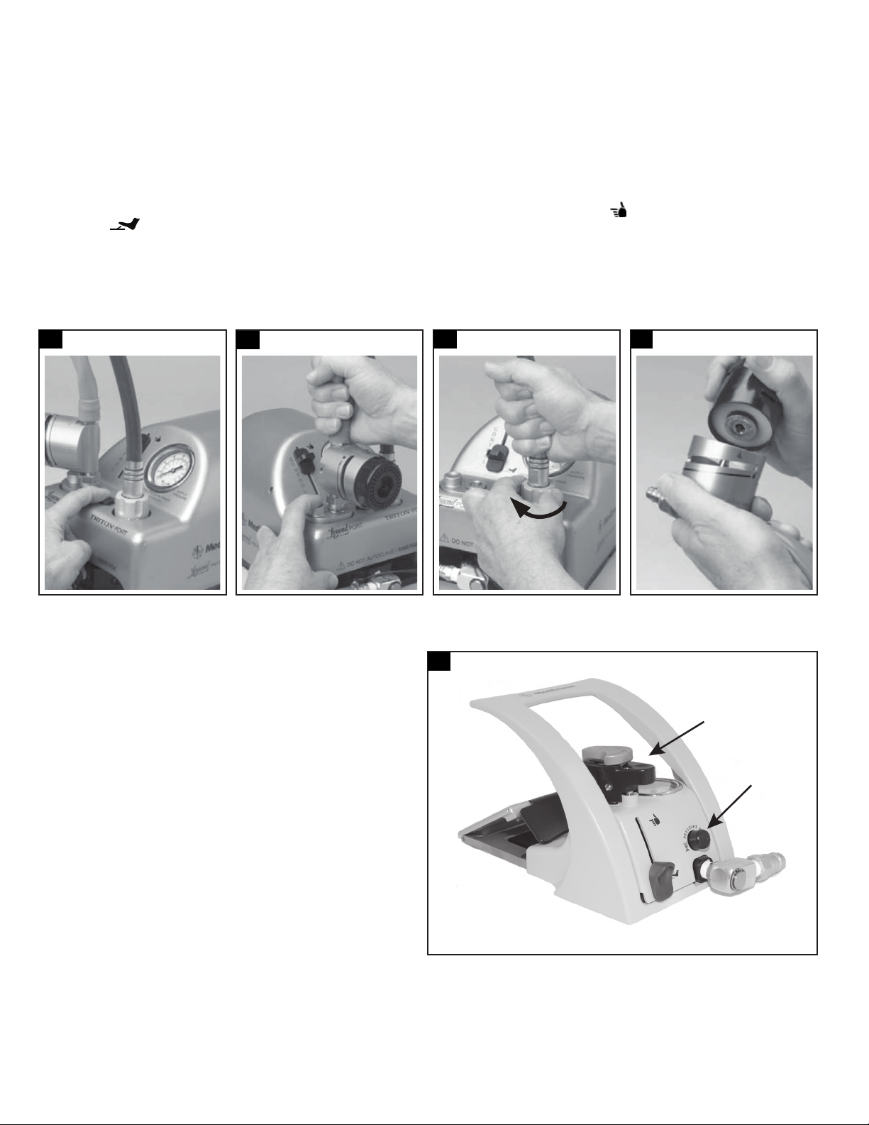
Midas Rex™ Legend™ Pneumatic High-Speed System
Disassembly of Legend equipment
1. Depressurize the system.
a. Turn o the tank or wall outlet compressed gas source.
b. Release pressure from the hose by depressing the pressure relief on the pneumatic control unit (Figure 28-1).
Warning: Refer to Warnings W72.
2. Disconnect hoses. Release motor hose from the pneumatic control unit by holding the motor’s exhaust hose rmly and depressing the Legend port connection
(Figure 28-2).
Notes:
• When releasing the Legend Gold Touch, depressing the Legend port connection will automatically release the “ ” position on the nger/foot control to
the “ “ position. The foot pedal will move upward to its non-running position.
• If using the TRITON Power Surgical Instrumentation System, hold the TRITON blue hose rmly and remove by turning TRITON quick connect coupler
clockwise (Figure 28-3).
3. Discard the lubricant/diuser cartridge. Unscrew the lubricant/diuser cartridge from the housing and discard according to local regulations (Figure 28-4).
Note: During removal of the lubricant/diuser cartridge, oil residue may be present. An absorbent cloth may be used to facilitate removal.
4. Remove attachment and tool. Follow the applicable disassembly instructions in the attachment disassembly sections and discard tool according to local regulations.
28-1
Legend disassembly Legend disassembly TRITON System Legend disassembly
28-2
28-3
28-4
Disassembly of MR7 equipment
1. Depressurize the system.
a. Turn o the compressed gas at the source.
b. Press the pressure relief button on the pneumatic control unit to release
remaining gas.
Warning: Refer to Warnings W72.
2. Disconnect hoses. Release the motor hose from the control unit by holding
the hose rmly and pressing the motor port connection button (Figure 29).
3. Discard the lubricant/diuser cartridge. Remove the lubricant/diuser
cartridge from the housing and discard it according to local regulations.
4. Remove the attachment and tool. Follow the applicable disassembly
instructions in the attachment disassembly sections and discard tool
according to local regulations.
29
MR7 disassembly
1
2
1. Motor port connection button 2. Pressure relief button
32
Midas Rex™ Legend™ Pneumatic High-Speed System
Cleaning and sterilization
Devices should be cleaned and then sterilized per the instructions below:
Reprocessing Instructions are subject to change. Refer to manuals.medtronic.com for current Reprocessing Instructions.
Notes:
• The reprocessing instructions provided below have been validated by the manufacturer as being capable of preparing the product for re-use. It remains the
responsibility of the processor to ensure that the reprocessing is actually performed using equipment, materials and personnel in the reprocessing facility to
achieve the desired result. This normally requires validation and routine monitoring of the process.
• All validations performed per AAMI TIR12, Designing, testing, and labeling reusable medical devices for reprocessing in health care facilities: A guide for medical
device manufacturers.
Medtronic recommends incineration of devices that have directly contacted patients suspected or conrmed with a Transmissible Spongiform Encephalopathy (TSE)/
Creutzfeldt-Jakob disease (CJD) diagnosis.
Cleaning brushes
Used to clean debris from lumen of attachments and telescoping tubes. Sized for an internal
bore diameter of 3.2 mm, 2.4 mm or 1.2 mm in Legend attachments.
Legend pneumatic motors reprocessing instructions
Warnings and
cautions
Limitations on
reprocessing
Point of use Follow hospital procedures.
Containment and
transportation
Preparation for
decontamination
Preclean instructions
prior to use in an
automated washer
Cleaning: Automated Caution: Do not use ultrasonic cleaner. Review the washer-disinfector warning above, before using this cleaning method.
Do not soak/submerge devices.
Do not use ultrasound to clean devices.
Do not use chlorine based or corrosive cleaning agents such as bleach, lye, acetone, sodium hypochlorite/bleach, sodium hydroxide,
formic acid, or solutions containing glutaraldehyde.
The use of a washer-disinfector for cleaning may cause a degradation in performance.
Allow an adequate cooling period after steam sterilization.
Legend Gold, Gold Touch, and Platinum instrument case (PA400) is not interchangeable with MR7 and MR7 Touch instrument case (PA600).
Utilize appropriate tray when sterilizing motors.
The product is provided non-sterile and must be cleaned and sterilized before the rst use and any reuse.
Verify functionality prior to re-use.
It is recommended that devices are reprocessed as soon as is practical following use.
Remove attachment from Legend Gold, Legend Gold Touch, and Legend Platinum motors and MR7 and MR7 Touch motors. Remove and
discard tool according to local regulations. Do not soak devices.
Rinse devices under running tap water with collet pointed down until no visible soil is noticed.
A nylon brush may be used to aid in cleaning.
Remove devices from instrument trays before placing into washer.
Verify devices are visually clean prior to placing in instrument washer.
Orient devices in the washer to ensure maximum exposure to the cleaning agents.
Clean per recommended washer cycle below.
Legend automated wash cycle using a neutral enzymatic detergent (pH 6.0-8.0)
Phase Recirculation time Water temperature Detergent type
Pre-wash 2 minutes (02:00) Cold water Not applicable
Wash 5 minutes (05:00) 66°C (151°F) (set point) Neutral enzymatic detergent, pH 6.0-8.0
Rinse 1 minute (01:00) Hot tap water Not applicable
Table 8. Disposable cleaning brush dimensions
Internal bore diameter Brush length
1.2 mm 20 cm (8 in)
2.4 mm 41 cm (16 in)
3.2 mm 41 cm (16 in)
Cleaning: Manual Wipe all external surfaces of the motor and cable with a cloth dampened with a neutral enzymatic detergent, pH 6.0-8.0.
Brush motor case and collet with a nylon brush dampened with a neutral enzymatic detergent.
Rinse motor thoroughly under running water, collet end pointed down. Dry collet and motor with lint-free towel.
Verify that devices are visually clean after manual cleaning.
Rinse thoroughly with tap water.
Disinfection Follow hospital procedures.
Packaging For sterilization, place devices in instrument tray. Devices may be unwrapped or wrapped with up to two layers of 1-ply polypropylene wrap
The instrument cases are not interchangeable. For sterilizing the Legend Gold, Gold Touch, and Platinum motors, use insturment case
(PA400). For sterilizing the MR7 and MR7 Touch motors, use instrument case (PA600).
33
Midas Rex™ Legend™ Pneumatic High-Speed System
Legend pneumatic motors reprocessing instructions
Sterilization Note: The temperatures and times for sterilization are the minimum required.
Legend 100% Ethylene Oxide (EO) sterilization parameters
Preconditioning
51-59 °C (124-138 °F),
70 ±5 % relative humidity,
Time: 30 minutes (30:00)
Legend Gold, Legend Gold Touch, Legend Platinum, MR7, and MR7 Touch steam sterilization
Cycle Pre-vac Gravity Pre-vac Pre-vac
Temperature 132°C (270°F) 132°C (270°F) 134°C (273°F) 134°C (273°F)
Time 4 minutes (04:00) 25 minutes (25:00) 3 minutes (03:00) 18 minutes (18:00)
Drying 15 minutes (15:00) 15 minutes (15:00) 10 minutes (10:00) 20 minutes (20:00)
STERRAD Not validated for use with low temperature hydrogen peroxide gas plasma sterilization.
Sterilization
temperature
51-59 °C
(124-138 °F)
Relative humidity EO concentration
70 +/- 5 % 725 +/- 25 mg/L 4 hours 51-59 °C (124-138
Gas exposure
(full-cycle)
Aeration
°F), 18 hours
Maintenance,
inspection, and
testing
Storage Store with other sterile devices.
Inspect devices for any damage before and after each use. If damage is observed, do not use the device until it is repaired.
Verify functionality prior to re-use.
Pneumatic control unit reprocessing instructions
Cleaning: Manual 1. Dampen a cloth with a neutral enzymatic detergent, pH 6.0-8.0, or a phenol based disinfectant, mixed according to manufacturer’s
instructions.
2. Wipe the foot pedal with the damp cloth until visually clean.
3. Dry the unit with a clean, non-abrasive cloth.
Attachments/tubes reprocessing instructions
Warnings and
cautions
Limitations on
reprocessing
Point of use Follow hospital procedures.
Containment and
transportation
Preparation for
decontamination
Preclean instructions
prior to use in an
automated washer
Do not soak/submerge devices.
Do not use ultrasound to clean devices.
Do not use chlorine based or corrosive cleaning agents such as bleach, lye, acetone, sodium hypochlorite/bleach, sodium hydroxide,
formic acid, or solutions containing glutaraldehyde.
The use of a washer-disinfector for cleaning may cause a degradation in performance.
Allow an adequate cooling period after steam sterilization.
The product is provided non-sterile and must be cleaned and sterilized before the rst use and any reuse.
Verify functionality prior to re-use.
It is recommended that devices are reprocessed as soon as is practical following use.
Detach attachment from motor. Remove and discard tool according to local regulations. Do not soak devices.
Rinse attachments/tubes under running tap water, until no visible soil is noticed.
Attachments with moving parts must be actuated through their full range of motion under running tap water.
While rinsing under running tap water, an appropriately sized nylon brush must be used internally (for straight, footed attachments and
telescoping tubes only) and/or externally to aid in cleaning attachments.
Remove devices from instrument trays before placing into washer.
Variable exposure attachments (AVAXX, AVAXXDK, AVSXX) must be placed in the washer with their tube in the fully extended position.
Verify devices are visually clean prior to placing in instrument washer.
Orient devices in the washer to ensure maximum exposure to the cleaning agents.
Clean per recommended washer cycle below.
34

Midas Rex™ Legend™ Pneumatic High-Speed System
Attachments/tubes reprocessing instructions
Cleaning: Automated Caution: Do not use ultrasonic cleaner. Review the washer-disinfector warning above, before using this cleaning method.
Legend attachments/tubes automated cleaning - neutral enzymatic detergent (pH 6.0-8.0)
Phase Recirculation time Water temperature Detergent type
Pre-wash 2 minutes (02:00) Cold water Not applicable
Wash 5 minutes (05:00) 66°C (151°F) (set point) Neutral enzymatic detergent, pH 6.0-8.0
Rinse 1 minute (01:00) Hot tap water Not applicable
Legend attachments/tubes automated cleaning - alkaline detergent (pH 8.0 -10.5)
Phase Recirculation time Water temperature Detergent type
Pre-wash 2 minutes (02:00) Cold tap water Not applicable
Wash 5 minutes (05:00) 43°C (109°F) (set point) Alkaline detergent with pH 8.0 - 10.5
Rinse 1 minute (01:00) Hot tap water Not applicable
Thermal rinse 1 minute (01:00) 90°C (194°F) (set point) Not applicable
Puried water rinse 1 minute, 30 seconds (01:30) 66°C (151°F) (set point) Not applicable
Cleaning: Manual Wipe all attachments and telescoping tubes with a cloth, dampened with a surgical instrument cleaning solution.
Immerse the head of contra-angle attachments in surgical instrument cleaning solution and run the motor for 1 minute.
Other attachments and tubes may be mechanically agitated in cleaning solution, but not soaked or immersed.
A nylon brush dampened with a surgical instrument cleaning solution may be used to clean the external surfaces and internal connecting
surfaces of the attachments and tubes.
Straight attachments, footed attachments and telescoping straight tubes have special cleaning brushes sized to the attachment’s or
telescoping tube’s internal diameter. Push the brush wet with surgical instrument cleaning solution through the attachment or telescoping
tube from rear to front to loosen and remove debris trapped inside.
Move any moveable parts back and forth to allow solution to thoroughly clean attachment, for example, sleeve on footed attachment,
perforator attachment.
Clean variable exposure attachments without adjusting the tube length rst, then with the tube fully extended, and nally with the tube
fully retracted.
Rinse thoroughly with tap water.
Drying and
lubrication
Disinfection Follow hospital procedures.
Packaging For sterilization, place devices in instrument tray. Devices may be unwrapped or wrapped with up to two layers of 1-ply polypropylene wrap.
Sterilization Note: The temperatures and times for sterilization are the minimum required.
Thoroughly dry attachments. An air gun may be used to blow moisture out from rear to front of attachment.
Note: Medtronic no longer recommends using the Legend attachment cleaning nozzle (PA120), as this may cause some attachments to overheat.
Using an aerosol spray lubricant (such as Pana Spray), perform the following steps to lubricate attachments:
Holding the can approximately 10-15 cm (3-6 inches) away from the attachment, spray all components that move, rotate, or slide with
three quick squirts.
Articulate movable components to ensure proper lubrication.
Remove excess lubricant with a clean cloth.
For sterilizing the attachment and tubes, either the PA400 instrument case or the PA600 instrument case may be used.
Legend attachments/tubes steam sterilization
Cycle Gravity Pre-vac Pre-vac (FR/WHO) Pre-vac (UK)
Temperature 132°C (270°F) 132°C (270°F) 134°C (273°F) 134°C (273°F)
Time 25 minutes (25:00) 4 minutes (04:00) 18 minutes (18:00) 3 minutes (03:00)
Drying 15 minutes (15:00) 15 minutes (15:00) 20 minutes (20:00) 10 minutes (10:00)
STERRAD Do not use low temperature hydrogen peroxide gas plasma sterilization due to lumen internal diameter and
length restrictions.
STERIS Do not use liquid peracetic acid sterilization due to immersion procedure.
Legend attachments/tubes 100% Ethylene Oxide (EtO) sterilization parameters
Preconditioning
51-59 °C (124-138 °F), 70 ±5 % relative
humidity, Time: 30 minutes (30:00)
Maintenance,
inspection, and
testing
Storage Store with other sterile devices.
Inspect devices for any damage before and after each use. If damage is observed, do not use the device until it is repaired.
Verify functionality prior to re-use.
Sterilization
temperature
51-59 °C
(124-138 °F)
Relative
humidity
70 +/- 5 % 725 +/- 25 mg/L 4 hours 51-59 °C (124-
EtO
Cconcentration
Gas exposure
(full-cycle)
Aeration
138 °F), 18 hours
35

Midas Rex™ Legend™ Pneumatic High-Speed System
Return policy for devices exposed to Transmissible Spongiform Encephalopathies (TSE)
MPSS will not authorize or accept the return of MPSS products that directly contact patients or is contaminated with a patient’s body uids who is suspected or
conrmed with a Transmissible Spongiform Encephalopathies / Creutzfeldt-Jakob Disease (TSE/CJD) diagnosis. Furthermore, MPSS recommends that all MPSS
products used on a patient conrmed with a TSE diagnosis be incinerated. Contact your Sales Representative for replacement of product incinerated under this
policy or for temporary equipment while original equipment is quarantined. Contact MPSS Regulatory Aairs Department for additional information regarding TSE
contamination. MPSS dissecting tools used on a patient suspected of a TSE/CJD diagnosis must be incinerated.
If TSE/CJD is excluded as a diagnosis, the quarantined reusable equipment may be returned for use after appropriate cleaning, decontamination and sterilization.
Hospital personnel should contact their infection control personnel for current procedures and policy for reusable equipment processing when suspect of
contamination with Creutzfeldt-Jakob Disease (CJD) or other Transmissible Spongiform Encephalopathies (TSE).
Reusable devices that have been used on patients with suspected Creutzfeldt-Jakob Disease (CJD) or other Transmissible Spongiform Encephalopathies (TSE) should
be quarantined and not reused until diagnosis is conrmed or excluded. Reusable devices should be quarantined after having been cleaned, decontaminated,
sterilized and packed in a ridged sealed container until nal diagnosis.
Preventative maintenance
Legend pneumatic high speed preventive maintenance/service program
The Midas Rex Legend Pneumatic High Speed System preventive maintenance/service program has been developed to assist you in getting the greatest ownership
value from your Midas Rex Legend Pneumatic High Speed System, while helping to maximize its performance, safety and reliability. The scheduled preventive
maintenance/service program is in addition to the required routine cleaning after each use. Please refer to the following preventive maintenance information for the
specic steps necessary to maintain Midas Rex Legend Pneumatic High Speed System.
Dening maintenance level
The following scheduled maintenance information is provided as a guide to assist the customer in getting the greatest ownership value from their Midas Rex Legend
Pneumatic System, while helping to maximize its performance, safety and reliability. This scheduled maintenance program is in addition to the required routine
cleaning after each use. (The scheduled maintenance program is one of three programs, Limited Warranty, and Extended Maintenance Agreement are the other two,
intended to help you keep your system in good condition.)
The maintenance information is divided into two sections.
Section 1 contains the preventive maintenance/service schedule. How much scheduled maintenance a Midas Rex Legend Pneumatic System requires depends upon
how often it is used and the conditions to which it is subjected, such as cleaning and sterilization. The demands on pneumatic systems can vary greatly from facility to
facility. Twelve maintenance intervals have been dened. The time interval is determined by tool usage per year per system and has been identied as levels A, B, C, or D
in accordance in Table 9.
Table 9: Maintenance level
Maintenance level
A 150–200 12–16* 3 months
B 100–149 8–11 4 months
C 50–99 4–7 5 months
D <50 <4 6 months
*A motor with usage rates greater than 16 uses per month should be returned for factory maintenance at a 6-month interval.
Note: Failure to follow recommended service and preventive maintenance schedules for attachments may prevent tool from being secured properly.
Identifying and following the scheduled maintenance level for a Midas Rex Legend Pneumatic System will assist in reducing the potential for unanticipated down
time as a result of wear.
The preventive maintenance schedule found in Section 1 details the specic checkpoints that are recommended and its associated interval. It also provides a
convenient place to document your system’s maintenance history. If any of these checkpoints indicate wear or damage, DO NOT USE. Return the respective product
to MPSS for service.
The maintenance checkpoints have been designed for a facility’s Biomedical Department or equivalent to perform.
Section 2 contains the detailed instructions for servicing the Midas Rex Legend Pneumatic System in accordance with the Twelve Maintenance Intervals.
Your Midas Rex Legend Pneumatic System has a limited warranty for a period of 1 year from the date of purchase for Gold, Gold Touch, and Platinum Motors, Hoses,
Pneumatic Control Unit with Pressure Hose, Regulator, Adapters, and Instrument Cases and Trays. Th e Attachments and Telescoping Tubes have a limited warranty
for a period of 90 days from the date of purchase. Aft er the warranty period, any costs incurred for repair/refurbishing become the responsibility of the customer.
Th is limited warranty does not include the cost associated with any of the factory level service requirements identi ed in the Preventive Maintenance Schedule.
Extended Maintenance Agreements are available. Please refer to the rst page insert for the Business Reply Card to obtain further information.
For service, please call 817-788-6440 or toll free 1-800-335-9557 to schedule. For additional or replacement products, please call 817-788-6400 or toll free
1-800-433-7080 to order.
Number of tools used per motor per year
Usage rate uses per month per motor Time interval
36

Midas Rex™ Legend™ Pneumatic High-Speed System
Section 1: Preventive maintenance/service schedule: 12 maintenance intervals
Date of system purchase:__________________ Maintenance level:__________________
Scheduled maintenance (See Section 2 for details)
Scheduled
maintenance
1st
2nd
3rd
4th
5th
6th
7th
8th
9th
10th
11th
12th
Attachments: Straight, footed, perforator, Jacobs Chuck, and telescoping Attachments: Angled, contra, and metal cutting
□ Etching and color ring remain legible and distinguishable.
□ Attachment tube and base are clean and free of debris.
□ Attachment has no loose components.
□ (Straight/footed) Attachment tip shows no signs of wear or deformation.
□ Footed attachment foot is not bent.
□ Collet on perforator or Jacobs Chuck drive attachment shows no signs of
wear or deformation.
□ Connect the attachment to the motor and run for 3 minutes. Motor case,
attachment base and tip do not become uncomfortably hot to the touch.
□ Repeat for each straight, footed, telescoping, perforator, and Jacobs Chuck
drive attachment in this system.
□ Note: Telescoping tubes are multi-use disposable. Discard if excessive heat or
vibration is present.
If any damage, excessive rust/corrosion, or wear is observed with the product, or if action is required beyond cleaning, do not use the product and return to MPSS for service.
Level A
months
3 4 5 6
6 8 10 12
9 12 15 18
12 16 20 24
15 20 25 30
18 24 30 36
21 28 35 42
24 32 40 48
27 36 45 54
30 40 50 60
33 44 55 66
36 48 60 72
Level B
months
Level C
months
Level D
months
Date performed Performed by
Factory service recommended - contact Medtronic
Factory service recommended - contact Medtronic
Factory service recommended - contact Medtronic
□ Etching and color ring remain legible and distinguishable.
□ Attachment tube and base are clean and free of debris.
□ Attachment has no loose components.
□ Attachment tip shows no signs of wear or deformation.
□ Connect the angled or metal cutting attachment to the motor and run for
3 minutes. Motor case, attachment base, knuckle and tip do not become
uncomfortably hot to the touch.
□ Head to tube joint for the contra-angled attachment is stable, that is, no play.
□ Connect the contra-angled attachment to the motor and run for 1 minute at
62,000rpm. Motor case, contra-angled attachment base, knuckle and tip do
not become uncomfortably hot to the touch
□ Repeat for each angled, contra-angled or metal cutting attachment in this
system.
Section 2: Instructions for completing preventive maintenance steps
Scheduled maintenance intervals 1, 2, 3, 5, 6, 7, 9, 10, 11
Motor
1. Visually inspect the exhaust (green) hose and ensure that it does not have any nicks, cracks, holes, tears, or other visible signs of wear.
2. Wipe the external surface of the exhaust (green) hose with a cloth. Perform the heat and seal check below (Step 6) and then inspect the hose. If an oily lm
remains on the hose, do not use and return the motor to MPSS for service.
3. Visually inspect the Lubricant/Diuser connection and ensure that the seals are present and that the connection area does not show any signs of damage that
would prevent the lubricant cartridge from tting properly.
4. Visually inspect the air tting and ensure that it does not exhibit any signs of damage.
5. Visually inspect the etching and ensure that it remains legible.
6. Heat and Seal Check
a. Attach and lock a straight or footed attachment onto the motor. Check to ensure that there is a tactile feel and an audible click when the attachment is
locked on the motor.
b. Connect the motor to a Foot Control unit attached to a compressed gas source.
c. Run the motor for 5 minutes.
d. Feel the motor case and the attachment base and ensure they are not uncomfortably hot to the touch.
e. Remove the Attachment and visually inspect the tool collet area, and the nger control valve area (for Gold Touch Motors) for any signs of oil.
7. (Gold Touch only) Run the motor for a short duration and then release the nger control lever. If the motor continues to run aft er the nger control lever is
released, do not use and return the motor to MPSS for service.
8. (Gold Touch only) Visually inspect the nger control lever and safety slide for any signs of debris or damage. Ensure the lever moves freely.
37

Midas Rex™ Legend™ Pneumatic High-Speed System
Attachments: Straight, footed, perforator, Jacobs Chuck, and telescoping
Telescoping tubes are multi-use disposable and do not receive scheduled maintenance.
1. Visually inspect the etching and color ring to ensure it remains legible and the color is distinguishable.
2. Visually inspect the attachment tube and base for any signs of debris or damage.
3. Visually and physically inspect (pulling and twisting by hand) the attachment for any loose or loosening components. If any components are loose, do not use
and return the attachment to MPSS for service.
4. (Straight/Footed) Visually inspect the attachment tip for any signs of wear. The tip should remain round with no evidence of deformation.
5. (Footed) Visually inspect the foot. The foot and/or leg of the attachment should not be bent or damaged.
6. (Perforator and Jacobs Chuck) Visually inspect the perforator collet for any signs of wear or deformation.
7. Heat Check
a. For telescoping attachment, insert an appropriate telescoping tube into the base.
b. Attach and lock the attachment onto the motor. Check to ensure that there is a tactile feel and an audible click when the attachment is locked on the motor.
c. Connect the motor to a Foot Control unit attached to a compressed gas source.
d. Run the motor for 5 minutes.
e. Feel the motor case, the attachment base, and the attachment tip (except Telescoping) to ensure they are not uncomfortably hot to the touch.
8. Repeat steps 1-7 for each straight/footed/perforator/Jacobs Chuck attachment that is part of this system.
Attachments: Angled, contra, and metal cutting
1. Visually inspect the etching and color ring to ensure it remains legible and the color is distinguishable.
2. Visually inspect the attachment tube and base for any signs of debris or damage.
3. Visually and physically inspect (pulling and twisting by hand) the attachment for any loose or loosening components. If any components are loose, do not use
and return the attachment to MPSS for service.
4. Visually inspect the attachment tip for any signs of wear. The tip should remain round with no evidence of deformation.
5. Heat Check Angled and Metal Cutting Attachment
a. Attach and lock the attachment onto the motor. Check to ensure that there is a tactile feel and an audible click when the attachment is locked on the motor.
b. Connect the motor to a Foot Control unit attached to a compressed gas source.
c. Run the motor for 5 minutes.
d. Feel the motor case, the attachment base, the knuckle (angled area for angled attachment only), and the attachment tip to ensure they are not
uncomfortably hot to the touch.
6. (Contra) Visually inspect the head to tube joint for the contra-angled attachment for stability; that is, there is no loosening of this joint.
7. Heat Check Contra-Angled Attachment
a. Attach and lock the contra-angled attachment onto the motor. Check to ensure that there is a tactile feel and an audible click when the attachment is locked
on the motor.
b. Connect the motor to a Foot Control unit attached to a compressed gas source.
c. Run the motor for 1 minute.
d. Feel the motor case, the attachment base, the knuckle (contra-angled area), and the attachment tip to ensure they are not uncomfortably hot to the touch.
8. Repeat steps 1-7 for each angled/contra-angled/metal cutting attachment that is part of this system.
Foot control and regulator
1. Visually inspect the air ttings and supply hose for any signs of blockage, damage, or wear.
2. Static Gage Check
a. Connect the foot control/regulator to a compressed gas source.
b. Pressurize the foot control/regulator.
c. Conrm that the gage is functional.
NOTE: This is a static functional test only. The pressure gages should be placed on your facility’s routine calibration schedule and be assessed for accuracy
during its regular calibration date.
3. (Foot Control) Pressure Relief Button Check
a. Connect the foot control to a compressed gas source.
b. Pressurize the foot control.
c. Turn o the compressed gas source.
d. Press the Pressure Relief Button.
e. Conrm that the compressed gas has been released and the gage on the foot control drops to zero.
4. (Foot Control) Finger/Foot Control Switch Functionality Check
a. Place the switch in the “ ” position.
b. Conrm the foot pedal is depressed.
c. Place the switch in the “ ” position.
d. Conrm the foot pedal is released.
5. (Foot Control) Visually inspect the Legend and TRITON port plugs for any signs of wear or damage and conrm that they remain connected to the foot control.
6. (Foot Control) Visually inspect the foot control pedal for any build-up of debris or indication of damage. Ensure the pedal moves freely.
7. (Foot Control) Pedal Check
a. Attach a Gold or Platinum motor to the foot control.
b. Connect the foot control to a compressed gas source.
c. Depress the foot control and run the motor for a short duration.
d. Release the foot control and observe the motor.
NOTE: If the motor continues to run aft er the foot pedal control lever is released, do not use and return the foot control to MPSS for service.
38

Midas Rex™ Legend™ Pneumatic High-Speed System
Scheduled maintenance intervals 4, 12
Motor, attachments: straight, footed, perforator, Jacobs Chuck, telescoping, angled, contra, and metal cutting
At these maintenance intervals it is important that the units be returned to MPSS for factory level inspection and service. Please call 817-788-6440 or toll free 1-800335-9557 to schedule. As a reminder, the costs associated with any of the factory level service requirements are not included in the limited warranty. Extended
Maintenance Agreements are available. Please refer to the rst page insert for the Business Reply Card to obtain further information.
Telescoping tubes are multi-use disposable and do not receive scheduled maintenance.
Contra-angled attachment
The Contra-angled attachment does not contain user or factory serviceable components and must be replaced at the 4th, 8th, and 12th maintenance intervals. Please
call 817-788-6400 or toll free 1-800-433-7080 to order.
Foot control and regulator
1. Visually inspect the air ttings and supply hose for any signs of blockage, damage, or wear.
2. Static Gage Check
a. Connect the foot control/regulator to a compressed gas source.
b. Pressurize the foot control/regulator.
c. Conrm that the gage is functional.
Note: This is a static functional test only. The pressure gages should be placed on your facilities routine calibration schedule and be assessed for accuracy
during its regular calibration date.
3. (Foot Control) Pressure Relief Button Check
a. Connect the foot control to a compressed gas source.
b. Pressurize the foot control.
c. Turn o the compressed gas source.
d. Press the Pressure Relief Button.
e. Conrm that the compressed gas has been released and the gage on the foot control drops to zero.
4. (Foot Control) Finger/Foot Control Switch Functionality Check
a. Place the switch in the “ ” position.
b. Conrm the foot pedal is depressed.
c. Place the switch in the “ ” position.
d. Conrm the foot pedal is released.
5. (Foot Control) Visually inspect the Legend and TRITON port plugs for any signs of wear or damage and conrm that they remain connected to the foot control.
6. (Foot Control) Visually inspect the foot control pedal for any build-up of debris or indication of damage. Ensure the pedal moves freely.
7. (Foot Control) Pedal Check
a. Attach a Gold or Platinum motor to the foot control.
b. Connect the foot control to a compressed gas source.
c. Depress the foot control and run the motor for a short duration.
d. Release the foot control and observe the motor. If the motor continues to run after the foot pedal control lever is released, do not use and return the foot
control to MPSS for service.
Scheduled maintenance intervals 8
Motor, attachments: straight, footed, perforator, Jacobs Chuck, telescoping, angled, contra, and metal cutting; foot control, and regulator
At this maintenance interval it is important that the units be returned to MPSS for factory level inspection and service. Please call 817-788-6440 or toll free 1-800335-9557 to schedule. As a reminder, the costs associated with any of the factory level service requirements are not included in the limited warranty. Extended
Maintenance Agreements are available. Please refer to the rst page insert for the Business Reply Card to obtain further information.
Telescoping tubes are multi-use disposable and do not receive scheduled maintenance.
Contra-angled attachment
The Contra-angled attachment does not contain user or factory serviceable components and must be replaced at the 4th, 8th, and 12th maintenance intervals. Please
call 817-788-6400 or toll free 1-800-433-7080 to order.
39

Midas Rex™ Legend™ Pneumatic High-Speed System
Refurbishing or repairs
When the Midas Rex Legend Pneumatic High Speed System requires servicing or refurbishing, contact MPSS Repair Services for a return authorization and
instructions for returning the equipment to MPSS, Fort Worth, Texas. MPSS provides quality assured service by factory-trained personnel who will utilize genuine
Midas Rex Legend parts as required.
Contact:
Medtronic Powered Surgical Solutions
4620 North Beach Street
Fort Worth, Texas 76137 USA
US Help Line (800-335-9557)
RS.DFWrepairs@medtronic.com
Peak performance, reliability and maximum service life from your Midas Rex Legend System may be assured by using only those Midas Rex Legend products for your
Midas Rex Legend System that are manufactured by and sold through MPSS, Fort Worth, Texas. While MPSS guarantees complete compatibility among its products
within a specic product line, the dissecting tools are designed for single-use only, and Medtronic disclaims any responsibility when reprocessed dissecting tools are
used. If you would like more information about the patient and product risks associated with reprocessed tools, please contact the number or e-mail address listed above.
Due to safety and environmental concerns, MPSS requests the return of pneumatic high speed motors for proper disposal at the end of the product life cycles.
Midas Rex Legend pneumatic high speed system limited warranty*
(U.S. Customers Only)
A. This Limited Warranty provides the following assurance to the purchaser of a Medtronic Midas Rex Legend Pneumatic High Speed System. The Midas Rex Legend
Pneumatic High Speed System includes the motor, foot control, instrumentation cases and trays (hereafter referred to as Motor Components), the attachments,
dissecting tools and other accessories not listed above and telescoping tubes (hereafter referred to as Accessory Components) and jointly referred to as Legend
Pneumatic High Speed System, unless specically noted.
i. Should a Motor Component fail to function within normal tolerances due to a defect in materials or workmanship within a period of one year from the date
of shipment of the new Motor Component, or 180 days from the date of shipment of the serviced or refurbished Motor Component to the purchaser (but not
less than the one year period from the date of shipment of the new Motor Component), or
ii. Should an Accessory Component fail to function within normal tolerances due to a defect in materials or workmanship within a period of 90 days from the
date of shipment of a new Accessory Component or serviced or refurbished Accessory Component to the purchaser, Medtronic will at its option: (a) issue a
credit to the purchaser of the replacement Motor Component or Accessory Component equal to the Purchase Price, as dened in Subsection A(3), against
the purchase of any same Motor Component or Accessory Component requested as its replacement, or, (b) provide a functionally comparable replacement
Motor Component or Accessory Component at no charge.
iii. As used herein, Purchase Price shall mean the lesser of the net invoiced price of the original or current functionally comparable, or replacement Motor
Component or Accessory Component.
B. To qualify for this Limited Warranty, these conditions must be met:
i. The Legend Pneumatic High Speed System must be used in accordance with the labeling and Instruction Manual provided with the products.
ii. Only Legend Pneumatic High Speed System dissecting tools that are manufactured, authorized, and quality controlled by Medtronic may be used.
iii. No reprocessed dissecting tools may be used.
iv. The Legend Pneumatic High Speed System may not be damaged by accident, abuse, misuse or tampering.
v. The Legend Pneumatic High Speed System may not be modied without the written permission of Medtronic.
C. This Limited Warranty is limited to its express terms. In particular:
i. Except as expressly provided by this Limited Warranty, MEDTRONIC IS NOT RESPONSIBLE FOR ANY DIRECT, INCIDENTAL OR CONSEQUENTIAL DAMAGES
BASED ON ANY DEFECT, FAILURE OR MALFUNCTION OF THE LEGEND PNEUMATIC HIGH SPEED SYSTEM TO FUNCTION WITHIN NORMAL TOLERANCES
WHETHER THE CLAIM IS BASED ON WARRANTY, CONTRACT, NEGLIGENCE, STRICT LIABILITY, OR OTHER TORT OR OTHERWISE.
ii. This Limited Warranty is made only to the purchaser. AS TO ALL OTHERS, MEDTRONIC MAKES NO WARRANTY, EXPRESS OR IMPLIED, INCLUDING BUT NOT
LIMITED TO, ANY IMPLIED WARRANTY OF MERCHANTABILITY OR FITNESS FOR A PARTICULAR PURPOSE, WHETHER ARISING FROM STATUTE, COMMON LAW,
CUSTOM OR OTHERWISE.
iii. The exclusions and limitations set out above are not intended to, and should not be construed so as to contravene mandatory provisions of applicable law.
If any part or term of this Limited Warranty is held to be illegal, unenforceable or in conict with applicable law by a court of competent jurisdiction, the
validity of the remaining portions of the Limited Warranty shall not be aected, and all rights and obligations shall be construed and enforced as if this
Limited Warranty did not contain the particular part or term held to be invalid. This Limited Warranty gives the purchaser specic legal rights. The purchaser
may also have other rights that vary from state to state.
iv. No such express or implied warranty to the purchaser shall extend beyond the period specied in A(1) above.
v. This Limited Warranty shall be the exclusive remedy available to any person.
vi. No person has any authority to bind Medtronic to any representation, condition, or warranty, except this Limited Warranty.
*This Limited Warranty is provided by Medtronic Powered Surgical Solutions, 4620 North Beach Street, Fort Worth, Texas 76137-4116. It applies only in the United
States. Areas outside the United States should contact their local Medtronic representative for terms of the warranty.
After the warranty period, any costs incurred for repair/refurbishing become the responsibility of the customer. This limited warranty does not include the cost associated
with any of the factory level service requirements identied in the preventive maintenance schedule. Extended maintenance agreements are available.
40

EC REP
STERILE
Control Unit
Dissecting Tool
REGULATOR
|
Symbols
The following symbols can appear on this device and related packaging.
Midas Rex™ Legend™ Pneumatic High-Speed System
Compliant with European Council
Directive MDD 93/42/EEC
Authorized Representative in the
European Community
Caution: Federal law (USA) restricts
this device to sale by or on the order
of a physician.
Consult Instructions for Use
Attention, see Instructions for Use.
Air Pressure Relief
Do Not Dispose Of This Product
In The Unsorted Municipal Waste
Stream. Dispose Of This Product
According to Local Regulations.
See Recycling.Medtronic.com for
Instructions On Proper Disposal Of
This Product.
If the single use symbol is on the
device label then this device is
designed for single patient use only.
Do not reuse, reprocess, or resterilize
this product. Reuse, reprocessing,
or resterilization may compromise
the structural integrity of the device
and/or create a risk of contamination
of the device, which could result in
patient injury, illness, or death.
Non-Sterile
Non-Sterile
Sterilized using Irradiation
Finger-Operated Control
Foot-Operated Control
+ XX °C
+ XX °F
+ XX °C
+ XX °F
Temperature Limitation
Manufacturer
Date of Manufacture
Use By Date
Serial Number
Catalog Number
Lot Number
Quantity
Is Approximately Equal To
Use With
Unlocked
Locked
Accessory
Adapter
Attachment
Brush
Control Unit
Lubricant/Diuser
Refurbished
! USA
Dissecting Tool
Instrument Case
Lubricant/Diuser
Motor
Refurbished
Regulator
Multi-Use Disposable Attachment
USA Only
On
O
Tool Control
Tube Control
Diameter
Part Number
Do not use if package is open or
damaged
Package Quantity
41

May be covered by U.S. Patents:
EC REP
2019-06
Medtronic.com/patents
©2019 Medtronic, Inc.
Made in USA. Printed in USA.
Medtronic Powered Surgical Solutions
4620 North Beach Street
Fort Worth, Texas 76137 USA
+1 800 643 2773
Medtronic B.V.
Earl Bakkenstraat 10
6422 PJ Heerlen
The Netherlands
+31 45 566 8000
Medtronic Australian Sponsor:
Medtronic Australasia Pty Ltd
2 Alma Road
Macquarie Park, NSW 2113 Australia
medtronic.com
manuals.medtronic.com
 Loading...