

Page 1

ADAPTA®/VERSA®/SENSIA®/
RELIA™
Adapta ADDR01/03/06
Adapta S ADDRS1
Adapta L ADDRL1
Adapta ADD01
Adapta ADVDD01
Adapta ADSR01/03/06
Versa VEDR01
Sensia SEDR01
Sensia L SEDRL1
Sensia SED01
Sensia SESR01
Sensia SES01
Relia REDR01
Relia RED01
Relia RESR01
Relia RES01
Relia REVDD01
Pacemaker Reference Guide
Page 2

Page 3

Contents
How to use this guide 9
1 Pacing modes 13
Introduction 14
Rationale for mode selection 15
Indications 17
Contraindications 17
MVP modes 18
DDDR mode 18
DDD mode 20
DDIR mode 21
DDI mode 22
DVIR mode 23
DVI mode 24
VDD mode 25
AAIR / ADIR modes 26
AAI / ADI modes 27
VVIR / VDIR modes 28
VVI / VDI modes 29
AAT / VVT modes 30
DOOR / AOOR / VOOR modes 31
DOO / AOO / VOO modes 32
ODO / OAO / OVO modes 33
2 Rate response 35
Introduction to rate responsive pacing 36
Preset rate response at implant 37
Rate Profile Optimization operation 39
Individualizing Rate Profile Optimization 46
Activity sensor operation 48
Manual control of Rate Profile Optimization 53
3 Pacemaker timing 55
Rates 56
Adapta/Versa/Sensia/Relia Pacemaker Reference Guide
Page 4

4
Contents
AV intervals 63
Rate Adaptive AV 66
Search AV+ and diagnostic 69
Blanking periods 73
Refractory periods 75
High rate atrial tracking 84
4 Lead/cardiac tissue interface 87
Implant Detection 88
Automatic polarity configuration 89
Lead Monitor 94
Lead impedance data 97
Capture Management and diagnostic 98
Sensing Assurance and diagnostic 118
Manually selecting pacing parameters 122
Manually selecting sensing parameters 125
Transtelephonic follow-up features 129
5 Special therapy options 133
Mode Switch and diagnostic 134
Managed Ventricular Pacing (MVP) 142
Conducted AF Response 147
Non-competitive atrial pacing 148
PMT intervention 150
PVC Response 153
Ventricular Safety Pacing 155
Sinus Preference 156
Atrial Preference Pacing 160
Rate Drop Response and diagnostic 164
Sleep Function 171
Single Chamber Hysteresis 173
6 Telemetry data 175
Establishing telemetry 176
Parameter summary 176
Patient information 178
Using TherapyGuide to select parameter values 179
Adapta/Versa/Sensia/Relia Pacemaker Reference Guide
Page 5

Battery and lead information 181
Marker Channel telemetry 182
Intracardiac electrograms 184
Extended Telemetry 186
7 Miscellaneous operations 187
Magnet Mode operation 188
Temporary programming 190
Electrical reset 191
Recommended Replacement Time (RRT/ERI) 193
Emergency pacing 194
8 Diagnostics 195
Introduction to diagnostics 196
Heart Rate Histograms 200
AV Conduction Histograms 202
Search AV+ Histogram 204
Sensor Indicated Rate Profile 205
High Rate Episodes 206
Ventricular Rate Histogram During Atrial Arrhythmias 213
Atrial Arrhythmia Trend 214
Atrial Arrhythmia Durations 216
Custom Rate Trend 216
Key Parameter History 219
Contents
5
9 Troubleshooting the pacing system 221
Troubleshooting strategy 222
Troubleshooting electrical problems 223
Troubleshooting hemodynamic problems 226
A Pacemaker description 231
Model number designator 232
Radiopaque codes 233
Physical dimensions 234
Connector dimensions 235
B Preset parameter settings 237
Shipping and nominal settings 238
Adapta/Versa/Sensia/Relia Pacemaker Reference Guide
Page 6

6
Contents
Electrical reset settings 251
Emergency settings 263
C Longevity projections 265
Projected service life 266
Prolonged service period 282
Recommended Replacement Time (RRT/ERI) 282
Battery specifications 283
D Telemetry and diagnostic values 285
Magnet Mode operations 286
Telemetry functions 287
Automatic diagnostics 290
Clinician-selectable diagnostics 292
Cardiac event counters 297
E Parameter values and restrictions 299
Programmable modes and parameters 300
Rate Response programming guidelines 315
F Implant information 317
Warnings 318
Precautions 320
Potential complications 328
Replace a device 329
Patient counseling information 330
G Glossary 333
Adapta/Versa/Sensia/Relia Pacemaker Reference Guide
Page 7

Adapta/Versa/Sensia/Relia 0
Pacemaker Reference Guide 0
A guide to the Adapta/Versa/Sensia/Relia pacemakers
Refer to the Adapta/Versa/Sensia/Relia Pacemaker Programming Guide for
information on software and programming.
Page 8

The following are trademarks of Medtronic:
Adapta, Checklist, Find Patient, Marker Channel, Medtronic, Medtronic Carelink, MVP,
Quick Look, Relia, Search AV, Sensia, SessionSync, TherapyGuide, and Versa.
Page 9

How to use this guide
Information is contained in two guides
Product information about Adapta/Versa/Sensia/Relia
pacemakers and the associated software for the 9790/C series
programmer and the 2090 programmer is presented in two
separate guides.
The Pacemaker Reference Guide (PRG) provides detailed
information on the pacemakers.
The Pacemaker Programming Guide (PPG) contains instructions
on how to use the programmer and the programming software.
About the Pacemaker Reference Guide
The Pacemaker Reference Guide describes in detail how the
pacemakers operate and specifies the capabilities of the
pacemakers. The PRG includes the following information:
■
Describes the pacing modes, rate response options, special
therapy features, telemetry types, and data collection options.
In some cases, guidelines are given on how to configure the
pacemaker operation.
■
Contains troubleshooting information for electrical and
hemodynamic problems.
■
Specifies parameter and data collection capabilities, longevity
projections, and mechanical and electrical specifications.
■
Provides general warnings and cautions, potential
interference sources, and general indications for pacing.
■
Contains a glossary of terms.
9
How to use this guide
Adapta/Versa/Sensia/Relia Pacemaker Reference Guide
Page 10

10
How to use this guide
About the Pacemaker Programming Guide
The Pacemaker Programming Guide describes how to program
Adapta, Versa, Sensia, and Relia pacemakers using a
programmer. The PPG presents the following information:
■
How to set up and configure the programmer and access
online help.
■
How to start a patient session, use the various follow-up
features during the session, and properly end the session.
■
How to use Checklist to streamline a follow-up session.
■
How to view and print the patient’s ECG and EGM waveform
traces.
■
How to configure the pacemaker to collect diagnostic data and
how to retrieve and view this information.
■
How to measure stimulation thresholds and sensing levels.
■
How to use TherapyGuide to obtain suggested parameter
values.
■
How to program parameter values and verify rate response
parameters settings.
■
How to run EP Studies.
The Implant Manuals supplement these guides
For each pacemaker model in the Adapta/Versa/Sensia/Relia
family, there is an Implant Manual. The Pacemaker Programming
Guide and the Pacemaker Reference Guide do not specify which
features apply to each individual pacemaker model. Refer to the
applicable implant manual for specific capabilities of individual
models.
Also, in various places throughout this manual, for example
“Programmable modes and parameters” on page 300, you are
asked to refer to the applicable implant manual for specific
capabilities of individual models
Adapta/Versa/Sensia/Relia Pacemaker Reference Guide
Page 11

How to use this guide
New nomenclature for product battery life terms
This manual uses a new nomenclature for certain terms related to
product battery life. This new nomenclature is defined in
CENELEC pacemaker standard EN 45502-2-1:2003, which
applies to Active Implantable Medical Devices (AIMD) intended to
treat bradyarrhythmias. This standard was approved and
published in December 2003.
Medtronic has adopted the new nomenclature to comply with the
CENELEC standard and in anticipation of the nomenclature
becoming an international standard.
The new nomenclature, and the terms replaced by the new
nomenclature, are presented in the following table:
New nomenclature Old nomenclature
BOS Beginning of Service BOL Beginning of Life
EOS End of Service EOL End of Life
11
RRT/ERI Recommended
Replacement Time
(RRT/ERI)
Prolonged service
period
Projected service life Longevity
ERI Elective Replacement
Post-ERI conditions
Indicator
Adapta/Versa/Sensia/Relia Pacemaker Reference Guide
Page 12

Page 13

Introduction 14
Rationale for mode selection 15
Indications 17
Contraindications 17
MVP modes 18
DDDR mode 18
DDD mode 20
DDIR mode 21
DDI mode 22
DVIR mode 23
DVI mode 24
VDD mode 25
Pacing modes1
1
AAIR / ADIR modes 26
AAI / ADI modes 27
VVIR / VDIR modes 28
VVI / VDI modes 29
AAT / VVT modes 30
DOOR / AOOR / VOOR modes 31
DOO / AOO / VOO modes 32
ODO / OAO / OVO modes 33
Page 14

14
Chapter 1
Introduction
Introduction
Pacing mode selection
This chapter provides an introduction to pacemaker modes as an
aid to pacing mode selection. The chapter is organized as follows:
Definition of basic pacing modes – The names for most of the
pacing modes are defined on the 1991 ACC/AHA guidelines for
pacemaker implantation.
1
Rationale for mode selection – In order to get pacing mode
suggestions, the use of TherapyGuide is recommended.
TherapyGuide is a programmer feature that suggests parameter
settings based on a patient's clinical conditions. For models which
do not contain TherapyGuide, refer to the device implant manual
for guidance in mode selection.
Mode descriptions – These descriptions provide indications and
contraindications for modes available with the pacemaker and
brief descriptions of how these modes operate.
NBG pacing codes
The pacemaker modes are defined in NBG Code.2 Each five-letter
NBG code describes a specific type of operation for implantable
pacemakers. For simplicity, this manual uses only the first three or
four letters, such as DDD, DDIR, DVIR, and so forth. Figure 1-1
describes the first four letters of the NBG code.
1
Dreifus LS, Fisch C, Griffin JC, et al. Guidelines for implantation of cardiac
pacemakers and antiarrhythmia devices. A report of the American College of
Cardiology/American Heart Association Task Force on Assessment of
Diagnostic and Therapeutic Cardiovascular Procedures (Committee on
Pacemaker Implantation). Journal of the American College of Cardiology. 1991;
18: 1-13.
2
Bernstein A., et al., “The NASPE/BPEG Pacemaker Code,” PACE, 10(4),
Jul-Aug 1987. (“NBG” stands for The North American Society of Pacing and
Electrophysiology [NASPE] and the British Pacing and Electrophysiology Group
[BPEG] Generic. NBG’s five-letter code supersedes the ICHD Code.
Adapta/Versa/Sensia/Relia Pacemaker Reference Guide
Page 15

Pacing modes
Rationale for mode selection
15
Further information
CHAMBER PACED
V = Ventricle
A = Atrium
D = Dual Chamber
S = Single Chamber
O = None
CHAMBER SENSED
V = Ventricle
A = Atrium
D = Dual Chamber
S = Single Chamber
O = None
Figure 1-1. NBG pacing codes
DDDR
MODE OF RESPONSE
T = Triggered
I = Inhibited
D = Double (Both)
O = None
PROGRAMMABLE/
RATE RESPONSE
P = Programmable
M = Multiprogrammable
C = Communicating
R = Rate Responsive
O = None
The mode descriptions in this chapter provide only a basic
overview of each mode. For further details on the rate response,
timing, and therapy capabilities, refer to “Rate response” on
page 36, “Pacemaker timing” on page 55, and “Special therapy
options” on page 133.
Rationale for mode selection
TherapyGuide offers a simple clinically-focused method for a
clinician to obtain suggested parameter values. At implant or an
early follow-up appointment, the clinician enters information about
the patient's clinical conditions. Based on those inputs the
programmer suggests parameter settings. The suggestions are
based on clinical studies, literature, current practice, and the
consensus of physicians.
For more information about TherapyGuide, refer to page 179.
For each pacemaker model, TherapyGuide suggests a
programmable mode. It bases the suggestion on clinical
conditions such as the condition of the sinus node and the quality
of AV conduction.
Adapta/Versa/Sensia/Relia Pacemaker Reference Guide
Page 16

16
Chapter 1
Rationale for mode selection
TherapyGuide offers a Rationale screen that shows the basis for
each setting of pacing modes and of other parameters. Figure 1-2
shows a typical Rationale screen. To access the screen, perform
the following steps:
Figure 1-2. Mode selection rationale used by TherapyGuide
1. Interrogate the pacemaker (before or after implant).
2. Select the Params icon. On the Therapy Parameters screen, select
the [TherapyGuide] button to open the TherapyGuide window.
3. Select the [Rationale…] button to open the Rationale window.
4. Select [Close] twice to return to the Therapy Parameters screen.
Note: It is not necessary to do any parameter programming at this
time. Refer to the Adapta/Versa/Sensia/Relia Pacemaker
Programming Guide for instructions on programming parameters
using TherapyGuide.
Adapta/Versa/Sensia/Relia Pacemaker Reference Guide
Page 17

Indications
Pacing modes
Indications
Note: This section contains information for all models of the
Medtronic Adapta/Versa/Sensia/Relia implantable pulse
generators. For information about a specific model or series, refer
to the implant manual for that device.
These Medtronic Adapta/Versa/Sensia/Relia implantable pulse
generators (IPGs) are indicated for use to improve cardiac output,
prevent symptoms, or protect against arrhythmias related to
cardiac impulse formation or conduction disorders.
These devices are indicated for use in patients who are
experiencing exercise intolerance or exercise restrictions related
to an arrhythmia. Using rate response modes may restore heart
rate variability and improve cardiac output.
Adapta/Versa/Sensia/Relia implantable pulse generators are
indicated for single use only.
This device is also indicated for VDD pacing in patients who have
adequate rates and one or both of the following conditions.
■
A requirement for ventricular pacing when adequate atrial
rates and adequate intracavitary atrial complexes are
present. This includes the presence of complete AV block
when atrial contribution is needed for hemodynamic
benefit or when pacemaker syndrome had existed or is
anticipated.
■
A requirement for intermittent ventricular pacing despite a
normal sinus rhythm and normal AV conduction.
17
Contraindications
Note: This section contains information for all models of the
Medtronic Adapta/Versa/Sensia/Relia implantable pulse
generators. For information about a specific model or series, refer
to the implant manual for that device.
There are no known contraindications for the use of pacing as a
therapy to control heart rate. The patient’s age and medical
condition may influence the selection of the pacing system, the
mode of operation, and the implant technique used by the
physician.
Adapta/Versa/Sensia/Relia Pacemaker Reference Guide
Page 18

18
Chapter 1
MVP modes
MVP modes
Rate responsive modes may be contraindicated for patients who
cannot tolerate pacing rates above the programmed Lower Rate.
Medtronic Adapta/Versa/Sensia/Relia implantable pulse
generators (IPGs) are contraindicated for the following
applications:
■
Use of an implantable cardioverter defibrillator (ICD) with a
unipolar-only IPG or in those cases in which unipolar leads are
implanted for the other models described. Pacing in the
unipolar configuration may cause the ICD to deliver
inappropriate therapy or to withhold appropriate therapy.
■
Dual chamber pacing in patients with chronic or persistent
supraventricular tachycardias, including atrial fibrillation or
flutter.
■
VDD mode operation in patients with sinus disorders.
■
Single chamber atrial pacing in patients with AV conduction
disturbance.
Two MVP modes are available: AAIR<=>DDDR and AAI<=>DDD.
Note: For information about AAIR<=>DDDR and AAI<=>DDD
modes, refer to “Managed Ventricular Pacing (MVP)” on page 142.
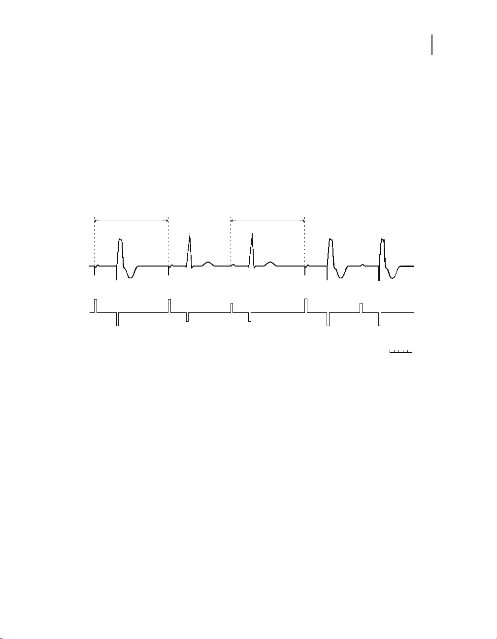
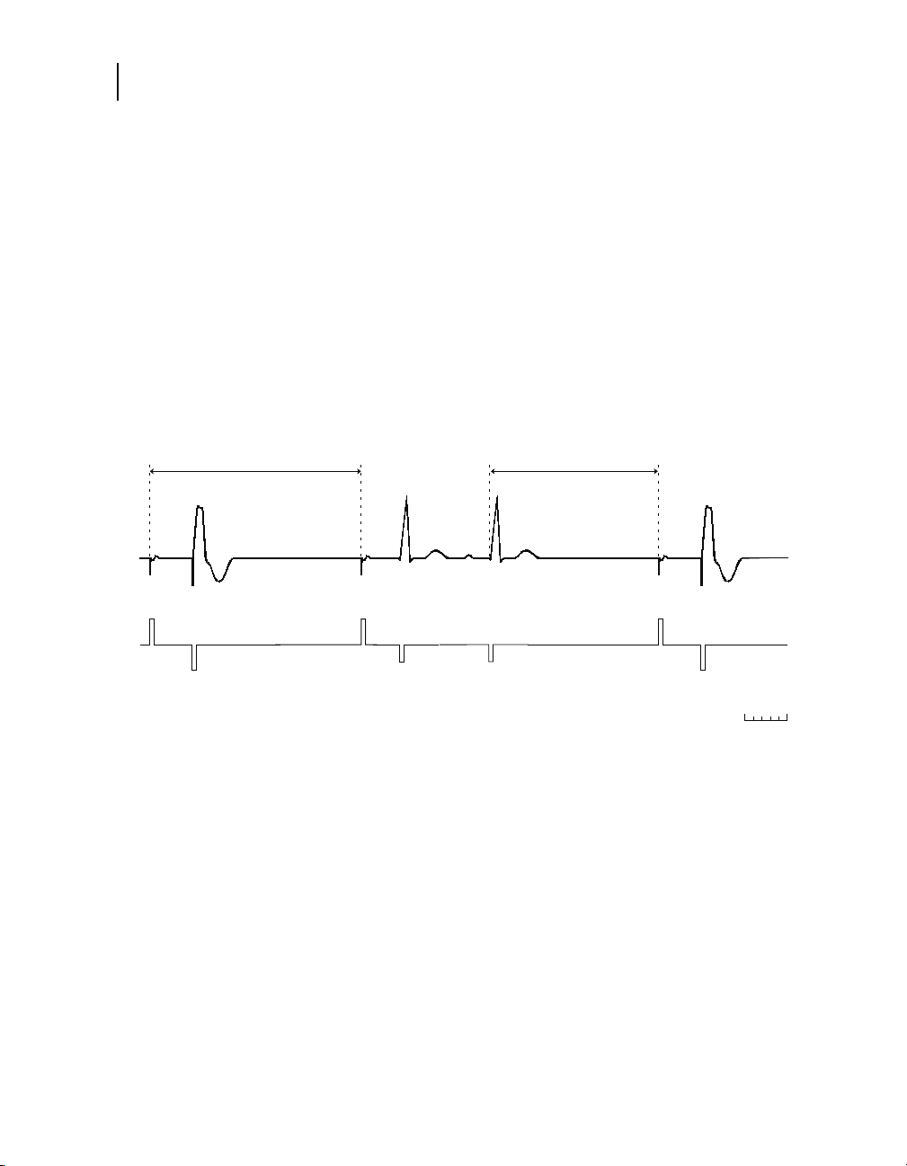
DDDR mode
Note: For information about the AAIR<=>DDDR mode, refer to
“Managed Ventricular Pacing (MVP)” on page 142.
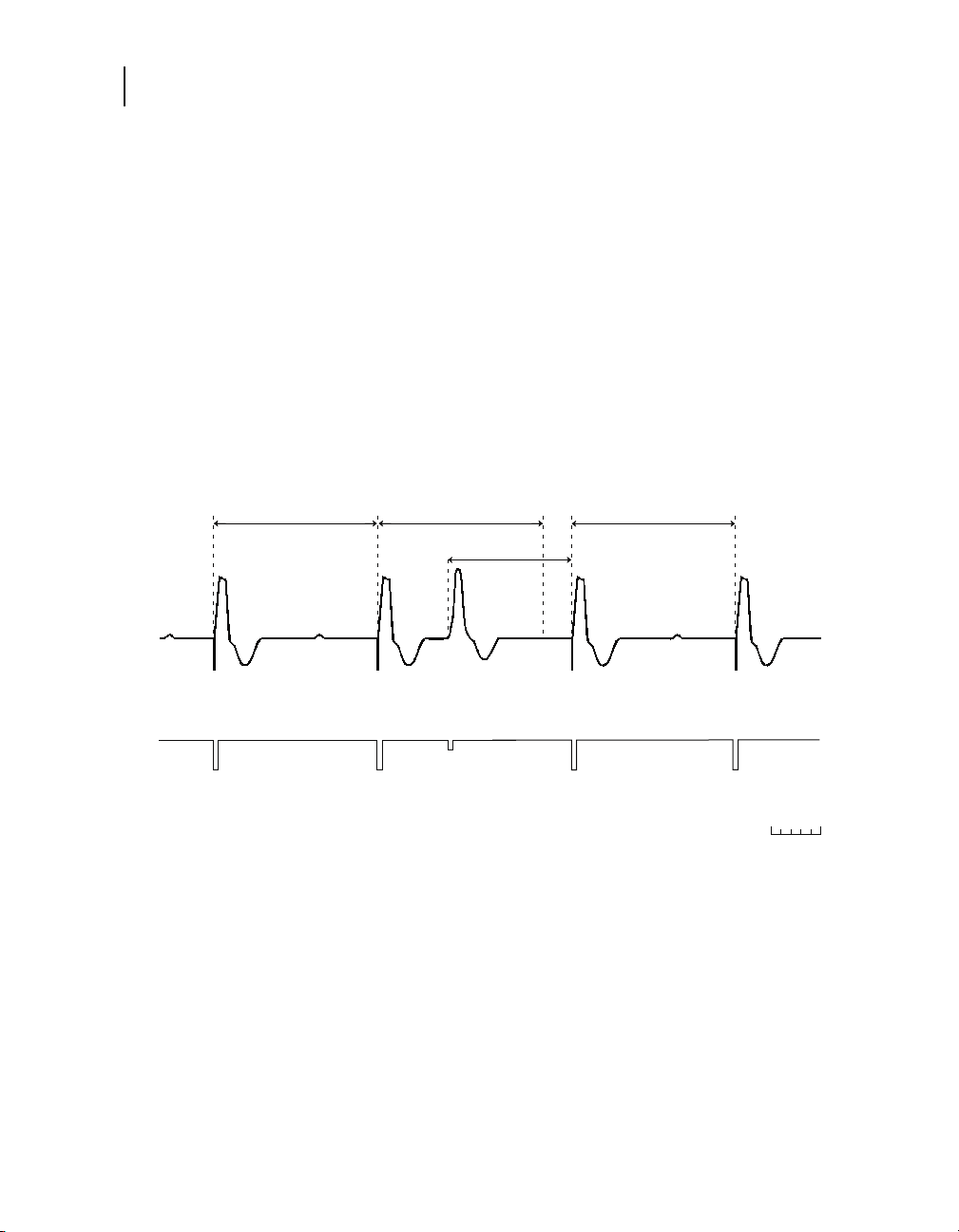
In the DDDR mode, the pacemaker tracks the faster of the intrinsic
atrial rate or the sensor-indicated rate. If the intrinsic rate is faster,
the DDDR mode provides atrial synchronous pacing; otherwise,
AV sequential pacing occurs at the sensor-indicated rate.
■
Rate limits for atrial tracking (Upper Tracking Rate)1 and
sensor tracking (Upper Sensor Rate) are separately
programmable.
1
The Total Atrial Refractory Period (TARP) may limit the tracking rate to a lesser
value. Refer to Chapter 3 for more information on TARP.
Adapta/Versa/Sensia/Relia Pacemaker Reference Guide
Page 19
Pacing modes
DDDR mode
■
The AV intervals that follow sensed atrial events (SAV) and
paced atrial events (PAV) are separately programmable, and
they can be programmed to shorten with increasing rates
(Rate Adaptive AV) or to change with intrinsic conduction
times (Search AV+).
■
A nonrefractory sensed event in either chamber inhibits
pacing in that chamber. A ventricular nonrefractory sensed
event in the VA interval that is not preceded by an atrial sense
(AS or AR) is a pacemaker-defined PVC and starts a new VA
interval.
19
Sensor-indicated
Interval
A
P
V
P
Parameters:
Lower Rate = 60 min
Sensor-indicated Rate = 90 min
(667 ms)
A
P
-1
(1000 ms) PAV Interval = 200 ms PVARP = 280 ms
Figure 1-3. Example of DDDR mode operation
V
S
-1
SAV Interval = 170 ms
Sensor-indicated
Interval
A
S
V
S
A
P
V
P
A
S
V
P
200 ms
Adapta/Versa/Sensia/Relia Pacemaker Reference Guide
Page 20
20
DDD mode
Chapter 1
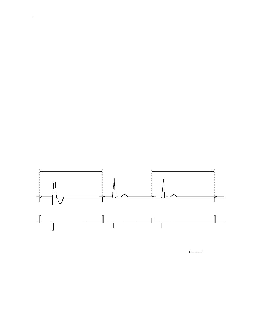
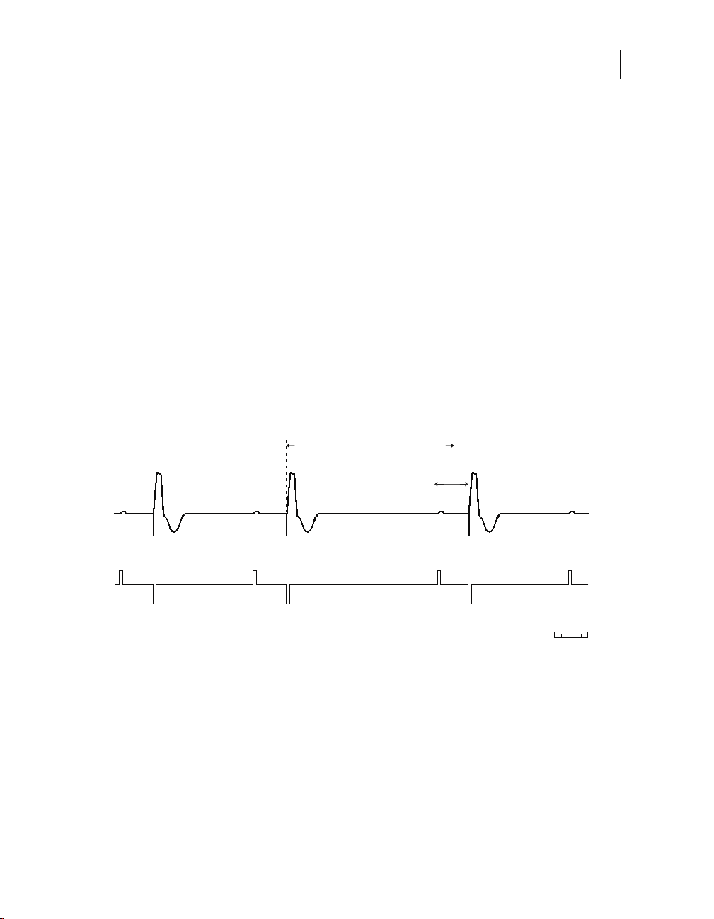
DDD mode
Note: For information about the AAI<=>DDD mode, refer to
“Managed Ventricular Pacing (MVP)” on page 142.
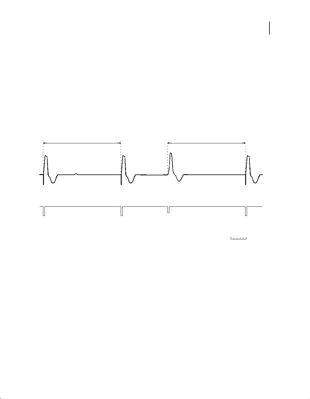
The DDD mode provides atrial synchronous pacing in the
presence of intrinsic atrial activity; otherwise, AV sequential
pacing occurs at the Lower Rate.
■
Each atrial paced or nonrefractory atrial sensed event starts
an AV interval and a lower rate interval. The AV intervals that
follow sensed atrial events (SAV) and paced atrial events
(PAV) are separately programmable, and the SAV may be
optionally programmed to shorten with increasing rate (Rate
Adaptive AV) or to change with intrinsic conduction times
(Search AV+).
■
A ventricular paced event may track an atrial sensed event up
to the programmed Upper Tracking Rate.
■
A ventricular nonrefractory sensed event in the VA interval that
1
is not preceded by an atrial sense (AS or AR) is a
pacemaker-defined PVC and starts a new VA interval.
Lower Rate Interval
A
P
V
P
Parameters:
Lower Rate = 60 min
-1
(1000 ms) PAV Interval = 200 ms
A
P
V
S
SAV Interval = 170 ms
Figure 1-4. Example of DDD mode operation
1
The Total Atrial Refractory Period (TARP) may limit the tracking rate to a lesser
value.
Adapta/Versa/Sensia/Relia Pacemaker Reference Guide
Lower Rate Interval
A
S
V
S
200 ms
A
P
Page 21
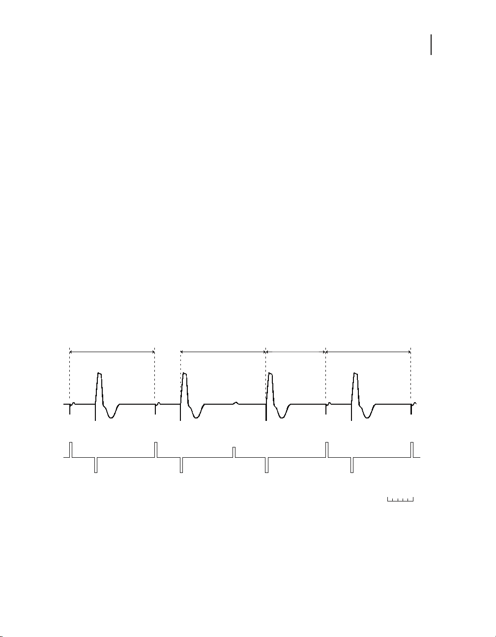
DDIR mode
Pacing modes
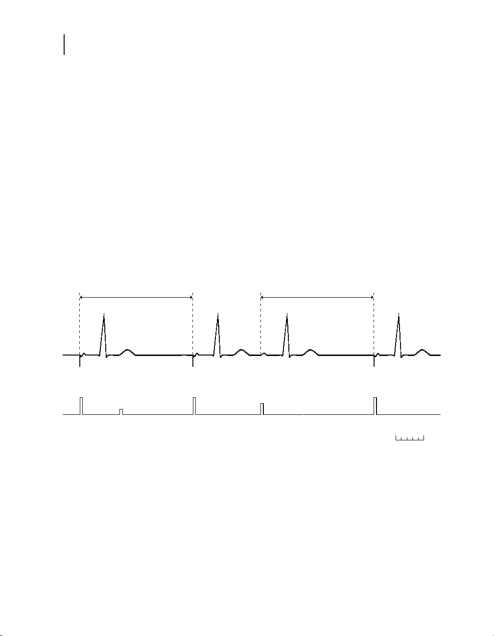
DDIR mode
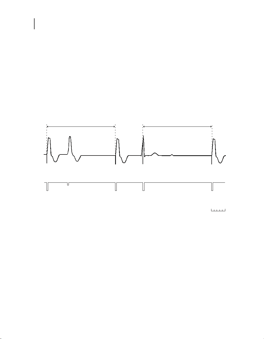
The DDIR mode provides dual chamber, sensor-driven,
atrioventricular (AV) sequential pacing for heart rate variation
without atrial tracking.
■
Atrial pacing occurs at the sensor-indicated rate. If it is not
inhibited, ventricular pacing occurs at the end of the PAV
interval.
■
The AV intervals that follow paced atrial events (PAV) are
separately programmable, and they can be programmed to
shorten with increasing rates (Rate Adaptive AV) or to change
with intrinsic conduction times (Search AV+).
■
An atrial event sensed outside the PVARP will inhibit a
scheduled atrial stimulus but will not start an AV interval. That
is, ventricular paced events after such sensed atrial events
occur at the sensor-indicated rate. The following
ventriculoatrial (VA) interval may be extended slightly to avoid
an increasing atrial paced rate.
■
A ventricular nonrefractory sensed event in the VA interval
starts a new VA interval.
21
Sensor-indicated
Interval
A
P
V
P
Parameters:
Lower Rate = 60 min
Sensor-indicated Rate = 90 min
-1
(1000 ms) PAV Interval = 200 ms
Figure 1-5. Example of DDIR mode operation
A
P
V
P
-1
(667 ms)
Sensor-indicated
Interval
A
S
Adapta/Versa/Sensia/Relia Pacemaker Reference Guide
Sensor-indicated VA
Interval
V
P
Sensor-indicated
A
A
P
P
V
P
Interval
200 ms
A
P
Page 22
22
Chapter 1
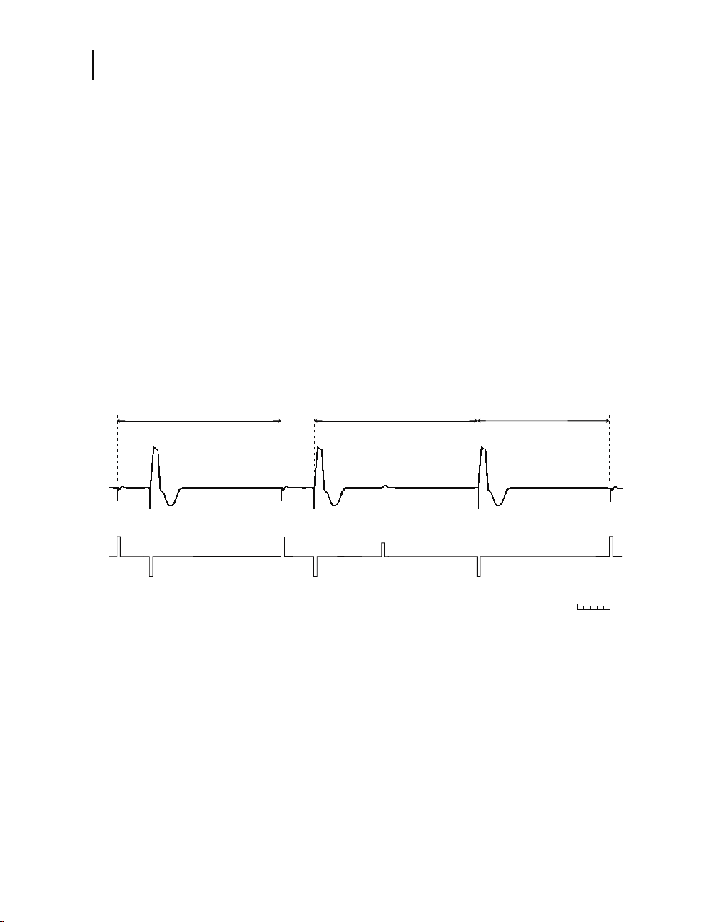
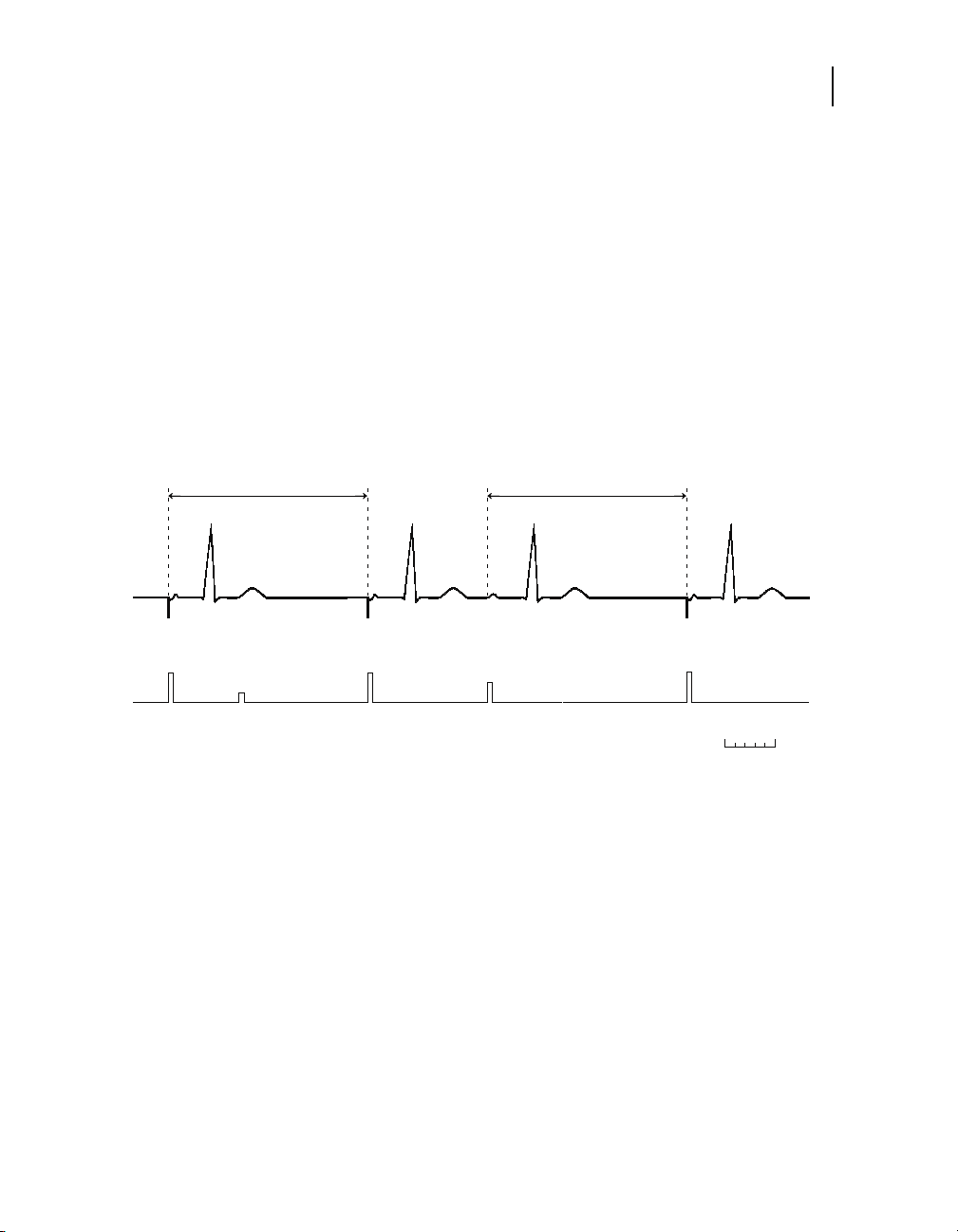
DDI mode
DDI mode
The DDI mode provides dual chamber atrioventricular (AV)
sequential pacing with atrial sensing but without atrial tracking.
■
Atrial pacing occurs at the Lower Rate. If it is not inhibited,
ventricular pacing occurs at the end of the PAV interval.
■
The AV intervals that follow paced atrial events (PAV) are
separately programmable, and they can be programmed to
change with intrinsic conduction times (Search AV+).
■
An atrial event sensed outside the PVARP will inhibit a
scheduled atrial stimulus but will not start an AV interval.
Ventricular paced events after such sensed atrial events occur
at the Lower Rate.
■
A ventricular nonrefractory sensed event in the ventriculoatrial
(VA) interval starts a new VA interval.
Lower Rate Interval
A
P
V
P
Parameters:
Lower Rate = 60 min
Lower Rate Interval Lower Rate VA Interval
A
P
V
P
-1
(1000 ms) PAV Interval = 200 ms
A
S
Figure 1-6. Example of DDI mode operation
A
P
V
P
200 ms
Adapta/Versa/Sensia/Relia Pacemaker Reference Guide
Page 23

DVIR mode
Pacing modes
DVIR mode
The DVIR mode provides AV sequential pacing at the
sensor-indicated rate unless inhibited by ventricular sensed
events.
■
Atrial pacing occurs at the sensor-indicated rate. If it is not
inhibited, ventricular pacing occurs at the end of the PAV
interval.
■
The AV intervals that follow paced atrial events (PAV) are
separately programmable, and they can be programmed to
shorten with increasing rates (Rate Adaptive AV) or to change
with intrinsic conduction times (Search AV+).
■
The DVIR mode ignores intrinsic atrial events. Sensing occurs
only in the ventricle. A ventricular nonrefractory sensed event
during the ventriculoatrial (VA) interval starts a new VA
interval.
23
Sensor-indicated
Interval
A
P
V
P
Parameters:
Lower Rate = 60 min
Sensor-indicated Rate = 90 min
-1
(1000 ms) PAV Interval = 200 ms
Figure 1-7. Example of DVIR mode operation
A
P
V
S
-1
(667 ms)
Sensor-indicated VA
Interval
V
S
Sensor-indicated
A
P
V
P
Interval
A
P
200 ms
Adapta/Versa/Sensia/Relia Pacemaker Reference Guide
Page 24
24
Chapter 1
DVI mode
DVI mode
The DVI mode provides dual chamber AV sequential pacing
without atrial sensing/tracking.
■
Atrial pacing occurs at the Lower Rate. If it is not inhibited,
ventricular pacing occurs at the end of the PAV interval.
■
The AV intervals that follow paced atrial events (PAV) are
separately programmable, and they can be programmed to
change with intrinsic conduction times (Search AV+).
■
Sensing occurs only in the ventricle, and intrinsic atrial events
are ignored. A ventricular nonrefractory sensed event during
the VA interval starts a new ventriculoatrial (VA) interval.
Lower Rate Interval
A
P
V
P
Parameters:
Lower Rate = 60 min
Lower Rate VA Interval
A
P
V
S
-1
(1000 ms) PAV Interval = 200 ms
V
S
Figure 1-8. Example of DVI mode operation
A
P
V
P
200 ms
Adapta/Versa/Sensia/Relia Pacemaker Reference Guide
Page 25
VDD mode
Pacing modes
VDD mode
The VDD mode provides atrial synchronous pacing (or VVI pacing
at the Lower Rate). The ventricle is paced synchronously up to the
programmed Upper Tracking Rate.
1
Sensing occurs in both the
atrium and ventricle, but pacing occurs only in the ventricle.
■
To promote atrial synchronous pacing at slow rates, a sensed
atrial event occurring near the end of the Lower Rate interval
will be followed by the programmed SAV interval. The result is
an extension of the ventricular lower rate.
■
The AV intervals that follow sensed atrial events (SAV) are
separately programmable, and they can be programmed to
shorten with increasing rates (Rate Adaptive AV) or to change
with intrinsic conduction times (Search AV+).
■
A ventricular nonrefractory sensed event in the V-V interval
that is not preceded by an atrial sense (AS or AR) is a
pacemaker-defined PVC, and it starts a new V-V interval.
Lower Rate Interval
SAV
Interval
25
A
S
V
P
Parameters:
Lower Rate = 60 min
Upper Tracking Rate = 120 min
-1
(1000 ms) SAV Interval = 200 ms
Figure 1-9. Example of VDD mode operation
1
The Total Atrial Refractory Period (TARP) may limit the tracking rate to a lesser
value.
A
S
V
P
-1
(500 ms) PVARP = 250 ms
Adapta/Versa/Sensia/Relia Pacemaker Reference Guide
A
S
V
P
A
S
200 ms
Page 26
26
pp
)
Chapter 1
AAIR / ADIR modes
AAIR / ADIR modes
Sensor-indicated Interval Sensor-indicated Interval
Note: For information about the AAIR<=>DDDR mode, refer to
“Managed Ventricular Pacing (MVP)” on page 142.
The AAIR mode provides atrial-based rate responsive pacing in
patients with intact AV conduction. Sensing and pacing occur only
in the atrium. In the absence of sensed events, the chamber is
paced at the sensor-indicated rate.
The ADIR mode operates the same as the AAIR mode except that
events sensed in the ventricle are recorded by the diagnostics.
When used in conjunction with Marker Channel recordings and
concurrent ECG, this mode may be used to observe the
conducted ventricular rhythm without affecting atrial pacing.
Note: In the AAIR and ADIR modes, atrial refractory sensed
events do not restart the Upper Sensor Rate interval.
A
P
A
R
A
P
A
S
A
P
200 ms
Parameters:
-1
Sensor-indicated Rate = 75 min
U
er Sensor Rate = 100 min-1 (600 ms
(800 ms) Atrial Refractory Period = 250 ms
Figure 1-10. Example of AAIR mode operation
Adapta/Versa/Sensia/Relia Pacemaker Reference Guide
Page 27
AAI / ADI modes
Note: For information about the AAI<=>DDD mode, refer to
“Managed Ventricular Pacing (MVP)” on page 142.
The AAI mode provides single chamber inhibited atrial pacing.
Sensing and pacing occur only in the atrium. Pacing occurs at the
programmed Pacing Rate unless inhibited by sensed events.
The ADI mode operates the same as the AAI mode except that
events sensed in the ventricle are recorded by the diagnostics.
When used in conjunction with Marker Channel recordings and
concurrent ECG, this mode may be used to observe the
conducted ventricular rhythm without affecting atrial pacing.
Pacing modes
AAI / ADI modes
27
Pacing Rate Interval
A
P
Parameters:
Pacing Rate = 75 min
A
R
Pacing Rate Interval
A
P
-1
(800 ms) Atrial Refractory Period = 250 ms
A
S
Figure 1-11. Example of AAI mode operation
A
P
200 ms
Adapta/Versa/Sensia/Relia Pacemaker Reference Guide
Page 28
28
Chapter 1
VVIR / VDIR modes
VVIR / VDIR modes
The VVIR mode provides ventricular rate responsive pacing in
patients for whom atrial-based pacing is deemed unnecessary or
inappropriate. In the absence of sensed events, the ventricle is
paced at the sensor-indicated rate.
The VDIR mode operates the same as the VVIR mode except that
events sensed in the atrium are recorded by the diagnostics.
When used in conjunction with Marker Channel recordings and
concurrent ECG, this mode may be used to observe the
underlying atrial rhythm without affecting ventricular pacing.
Note: In the VVIR and VDIR modes, ventricular refractory sensed
events restart the Upper Sensor Rate interval.
Sensor-indicated
Interval
V
P
Parameters:
Lower Rate = 60 min
Sensor-indicated Rate = 90 min
-1
(1000 ms) Upper Sensor Rate = 120 min-1 (500 ms)
Figure 1-12. Example of VVIR mode operation
Sensor-indicated
Interval
Upper Sensor
Rate Interval
V
P
-1
(667 ms) Ventricular Refractory Period = 300 ms
V
R
Sensor-indicated
Interval
V
P
V
P
200 ms
Adapta/Versa/Sensia/Relia Pacemaker Reference Guide
Page 29
VVI / VDI modes
The VVI mode provides single chamber inhibited pacing at the
programmed Pacing Rate unless inhibited by sensed events.
Sensing occurs only in the ventricle.
The VDI mode operates the same as the VVI mode except that
events sensed in the atrium are recorded by the diagnostics.
When used in conjunction with Marker Channel recordings and
concurrent ECG, this mode may be used to observe the
underlying atrial rhythm without affecting ventricular pacing.
Pacing modes
VVI / VDI modes
29
Pacing Rate Interval
V
P
Parameters:
Pacing Rate = 60 min
Ventricular Refractory Period = 300 ms
-1
(1000 ms)
Figure 1-13. Example of VVI mode operation
Pacing Rate Interval
V
P
V
S
200 ms
V
P
Adapta/Versa/Sensia/Relia Pacemaker Reference Guide
Page 30
30
Chapter 1
AAT / VVT modes
AAT / VVT modes
In the AAT and VVT modes, pacing occurs at the programmed
Lower Rate, but a nonrefractory sensed event triggers an
immediate pacing output (rather than inhibiting such output). With
the exception that pacing outputs occur when events are sensed,
the triggered modes operate identically to the corresponding
inhibited modes.
Note: Programmed triggered pacing will not occur faster than
300 ms (200 min
programmed triggered pacing is not limited to 300 ms (200 min
Pacing Rate Interval
V
P
Parameters:
Pacing Rate = 60 min
Ventricular Refractory Period = 300 ms
V
R
-1
(1000 ms)
Figure 1-14. Example of VVT mode operation
-1
) from the previous paced event. Temporary
Pacing Rate Interval
V
P
T
P
V
P
200 ms
-1
).
Adapta/Versa/Sensia/Relia Pacemaker Reference Guide
Page 31

DOOR / AOOR / VOOR modes
The DOOR, AOOR, and VOOR modes operate as follows:
■
The DOOR mode provides asynchronous AV sequential
pacing at the sensor-indicated rate. Intrinsic events are
ignored.
■
The AOOR and VOOR modes provide single chamber pacing
at the sensor-indicated rate. Intrinsic events are ignored.
Pacing modes
DOOR / AOOR / VOOR modes
31
Sensor-indicated
Interval
A
P
V
P
Parameters:
Lower Rate = 60 min
Sensor-indicated Rate = 90 min
A
P
-1
(1000 ms) PAV Interval = 200 ms
Figure 1-15. Example of DOOR mode operation
Sensor-indicated
Interval
V
P
-1
(667 ms)
Sensor-indicated
Interval
A
P
V
P
Sensor-indicated
Interval
A
P
V
P
A
P
200 ms
Adapta/Versa/Sensia/Relia Pacemaker Reference Guide
Page 32

32
Chapter 1
DOO / AOO / VOO modes
DOO / AOO / VOO modes
The DOO, AOO, and VOO modes operate as follows:
In addition to being directly programmable, the DOO mode is the
Magnet mode of the corresponding dual chamber modes, except
for the VDD mode, which is the VOO mode. AOO and VOO modes
are the Magnet modes of the corresponding atrial and ventricular
single chamber modes, respectively.
■
The DOO mode provides AV sequential pacing at the
programmed Lower Rate with no inhibition by intrinsic events.
■
The AOO and VOO modes provide pacing at the programmed
Lower Rate with no inhibition by intrinsic events in the
applicable chamber.
Lower Rate Interval
A
P
V
P
Parameters:
Lower Rate = 60 min
(1000 ms)
Lower Rate Interval Lower Rate Interval
A
P
V
P
-1
PAV Interval = 200 ms
A
P
Figure 1-16. Example of DOO mode operation
A
P
V
P
200 ms
Adapta/Versa/Sensia/Relia Pacemaker Reference Guide
Page 33

ODO / OAO / OVO modes
Warning: Never program these modes for pacemaker-dependent
patients. For such patients, use the programmer’s inhibit function
for brief interruption of outputs.
In the ODO, OAO, and OVO modes, sensing occurs in the
designated chamber or chambers. When used in conjunction with
Marker Channel telemetry and concurrent ECG, these modes may
be used to observe underlying rhythms.
■
Blanking periods in these modes are automatically minimized
to maximize the sensing window or windows. Thus, Marker
Channel telemetry may display sense markers for cardiac
events (for example, far-field R waves) that otherwise would
not appear due to longer blanking.
■
No timing intervals or refractory periods are used.
Pacing modes
ODO / OAO / OVO modes
33
Adapta/Versa/Sensia/Relia Pacemaker Reference Guide
Page 34

Page 35

Introduction to rate responsive pacing 36
Preset rate response at implant 37
Rate Profile Optimization operation 39
Individualizing Rate Profile Optimization 46
Activity sensor operation 48
Manual control of Rate Profile Optimization 53
Rate response2
2
Page 36

36
Chapter 2
Introduction to rate responsive pacing
Introduction to rate responsive pacing
Rate response
The pacemaker may provide appropriate rate response for
patients who require cardiac pacing support at both submaximal
and maximal rates. Submaximal rates are moderate pacing rates
near the Activities of Daily Living Rate (ADL Rate) obtained during
typical daily activities, such as walking or daily chores. Maximal
rates are rates (at or near the Upper Sensor Rate) obtained during
vigorous activities. To achieve appropriate rate response, the
pacemaker provides activity sensor-driven pacing with rate
response control in both the ADL rate range and the exertion
rate range.
The pacemaker provides appropriate rate response by employing
the following operations:
■
Three programmable rates control the submaximal and
maximal rate ranges: Lower Rate, ADL Rate (Activities of
Daily Living Rate), and Upper Sensor Rate. The ADL Rate is
equivalent to the average target rate that the patient achieves
for moderate activities.
■
Independent control of rate response is provided in both the
ADL and exertion rate ranges.
Automatic features
For models in a rate responsive mode, the pacemaker
automatically enables rate response after implant and
automatically adjusts rate response, if necessary, once each day.
■
During the first 30 minutes after implant, pacing occurs at the
implanted mode but without rate response. 30 minutes after
implant, rate response operation is enabled.
■
Once each day, rate response is assessed and adjusted, if
necessary, in the ADL and exertion rate ranges. The
assessment is based on comparing the pacemaker’s historical
sensor-indicated rate profiles against a clinician prescribed
target rate profile of the patient. If the rate profiles differ, rate
response is adjusted slightly in the appropriate rate range, and
the assessment is repeated again the next day.
Adapta/Versa/Sensia/Relia Pacemaker Reference Guide
Page 37

For further information
Refer to “Rate Profile Optimization operation” on page 39 for
information on how the pacemaker optimizes rate response.
Preset rate response at implant
Overview
Pacemakers shipped in rate responsive modes operate in a non
rate responsive mode until implant detection is completed, which
is typically 30 minutes after implant. Thereafter, the pacemakers
automatically enable rate responsive pacing. Consequently, no
programming is required for rate response operation.
Three pacing rate controls
If customization of rate response is desired, three pacing rates are
provided to control the ADL and exertion rate ranges:
■
Lower Rate defines the slowest rate at which pacing occurs in
the absence of a sinus rate or physical activity.
■
ADL Rate (Activities of Daily Living Rate) is the approximate
rate that the patient’s heart is expected to reach during
moderate exercise.
■
Upper Sensor Rate provides the upper limit for the
sensor-driven rate during vigorous exercise.
Rate response
Preset rate response at implant
37
Refer to “Rates” on page 56 for additional considerations when
selecting pacemaker rates.
Adapta/Versa/Sensia/Relia Pacemaker Reference Guide
Page 38

38
Chapter 2
Preset rate response at implant
Starting rate response immediately
In situations where the clinician wishes to start rate responsive
pacing before the 30-minute implant detection period is
completed, perform the following steps:
1. After the device is implanted, program Implant Detection to
“Off/Complete.”
2. Configure pace and sense lead polarities and Lead Monitor.
3. Verify that Rate Profile Optimization is On.
4. Verify that the parameter values for Lower Rate, ADL Rate,
and Upper Sensor Rate are appropriate.
5. Verify that the parameter values for ADL Response, Exertion
Response, Activity Threshold, Activity Acceleration, and
Activity Deceleration are appropriate.
For further information
Refer to “Rate Profile Optimization operation” on page 39 and
“Individualizing Rate Profile Optimization” on page 46.
Adapta/Versa/Sensia/Relia Pacemaker Reference Guide
Page 39

Rate Profile Optimization operation
Rate Profile Optimization operation
Overview
When Rate Profile Optimization is programmed On, the
pacemaker can adapt ADL and exertion rate response levels once
each day by comparing the patient’s current sensor rate profiles
against a target rate profile. This feature is intended to provide
automatic and independent monitoring of rate response at both
moderate rates for daily patient activities, such as walking and
daily chores, and at exertion rates for vigorous patient activities.
Optimization can be individualized to the patient’s activity levels.
Refer to “Individualizing Rate Profile Optimization” on page 46.
Optimization can also operate in the background when a non rate
responsive mode is programmed. This can provide appropriate
rate response to patient activity if rate response is needed later or
for certain therapy features, such as mode switching to a non-atrial
tracking rate responsive mode.
Rate control in the ADL and exertion rate ranges
Rate response
39
The pacemaker maintains linear rate control between the activity
sensor signal and the sensor-indicated rate from the Lower Rate
to the ADL Rate. Refer to “How Activity Threshold influences rate”
on page 48. It maintains independent linear rate control in the
exertion rate range. Optimization controls how rapidly and to what
level the sensor-indicated rate increases and decreases in these
two rate ranges. The three programmable rate controls [Lower
Rate, ADL Rate (Activities of Daily Living Rate), and Upper Sensor
Rate] define the rate ranges (see Figure 2-1).
■
Moderate pacing rates are achieved during typical daily
patient activities. These rates (in the ADL rate range) are at or
near the ADL Rate.
■
Exertion pacing rates are achieved during vigorous activities.
These rates (in the exertion rate range) are at or near the
Upper Sensor Rate
Adapta/Versa/Sensia/Relia Pacemaker Reference Guide
Page 40

40
Chapter 2
Rate Profile Optimization operation
Figure 2-1 shows a graph of sensor-indicated rate as a function of
increasing activity. The sensor-indicated rate curve has two
slopes. The first slope, which controls how aggressively the pacing
rate increases from the Lower Rate to the ADL Rate, is determined
by the programmed ADL Response parameter. The second slope,
which controls how aggressively the pacing rate approaches the
Upper Sensor Rate, is determined by the programmed Exertion
Response parameter.
When you program new values for rates or Rate Profile
Optimization, immediate changes occur. The new values are
predictions based on automatic diagnostic data and the selected
Rate Profile Optimization settings. The pacemaker continues to
adjust Rate Response over time.
Note: If the patient does not have any data in the Sensor Indicated
Rate Profile diagnostic, optimization does not adjust immediately
when these parameters are programmed. 24 hours of diagnostic
data are required.
ADL rate
Upper
Sensor
Rate
ADL Rate
Lower Rate
Figure 2-1. A sensor-indicated rate curve
range
Increasing activity →
Exertion rate
range
Adapta/Versa/Sensia/Relia Pacemaker Reference Guide
Page 41

Optimization using rate profiles
Optimization of rate response occurs independently in both the
ADL rate range and the exertion rate range. The sensor-indicated
rate curve is assessed daily based on the following rate profile
data:
Sensor rate profile – An actual rate versus time distribution of
the patient’s averaged sensor-indicated rates. Once each day, the
pacemaker collects a daily sensor rate profile and cumulates the
data into a long-term average. Both the daily and long-term rate
profiles are assessed each day to determine if adjustments to rate
response are required. The long-term sensor rate profile is
automatically stored in the Sensor Indicated Rate Profile
diagnostic.
Target rate profile – A programmable rate versus time
distribution of the patient’s desired rates. The ADL Response and
Exertion Response parameters define the percentage of time that
the sensor-indicated rate stays in the ADL rate range and in the
exertion rate range, respectively.
Figure 2-2 shows a typical rate profile (either a sensor rate profile
or a target rate profile).
Rate response
Rate Profile Optimization operation
41
30%
20%
10%
Percentage of time
Lower Rate ADL Rate Upper Sensor
Figure 2-2. Example of a rate profile
Adapta/Versa/Sensia/Relia Pacemaker Reference Guide
ADL rate
range
Exertion rate
range
Rate
Page 42

42
Chapter 2
Rate Profile Optimization operation
Daily optimization of rate response
Once each day, the pacemaker evaluates the percentage of time
the sensor rate is in the ADL and exertion rate ranges by
comparing the daily and long-term sensor rate profiles against the
target rate profile. This operation follows the sequence shown in
Figure 2-3.
■
The pacemaker calculates the sensor indicated rate based on
the activity sensor signal.
■
From the actual sensor indicated rate values, it generates a
daily sensor rate profile. It also merges that data into a
long-term sensor rate profile.
■
It compares the target rate profile to the daily and long-term
sensor rate profiles. Refer to Figure 2-4 and Figure 2-5 for
details.
■
If the sensor rate profiles match the target rate profile or if the
daily and long-term sensor rate profiles contradict each other,
no rate response adjustments occur.
■
Otherwise it makes an automatic adjustment to rate response,
which affects the calculation of the sensor-indicated rate in
either or both of the rate ranges.
■
This sequence repeats each day.
As a result of this operation, the pacemaker automatically adjusts
rate response in the ADL and exertion ranges, if necessary, based
on the following criteria:
■
If the sensor rate profiles show a higher percentage of time
spent pacing than the target rate profile, rate response for the
pertinent rate range is set to be less responsive. Conversely, if
a lower percentage of time spent pacing is profiled than
targeted for, rate response is set to be more responsive.
■
If the sensor rate profiles match the target rate profile or the
daily and long-term sensor rate profiles contradict each other,
no rate response adjustments occur.
Adapta/Versa/Sensia/Relia Pacemaker Reference Guide
Page 43

Rate response
Rate Profile Optimization operation
43
Sensor signal
processing
Rate calculation
Daily sensor
Adjust ADL rate
response as needed
based on
comparison
rate profile
30%
20%
10%
Compare
Adjust exertion rate
response as needed
based on
comparison
Figure 2-3. Daily operation of Rate Profile Optimization
Long-term sensor
rate profile
30%
20%
10%
Compare
30%
20%
10%
Target rate profile
Adapta/Versa/Sensia/Relia Pacemaker Reference Guide
Page 44

44
Chapter 2
Rate Profile Optimization operation
The goal of this operation is to keep the patient’s sensor rate
profiles equivalent to the target rate profile. This is shown in two
examples.
In Figure 2-4, a comparison of the sensor rate profile and target
rate profile shows that pacing in the ADL rate range occurs for a
larger percentage of time than was targeted. In the sensor rate
curve, rate response is adjusted to be less aggressive in this
range.
The same comparison shows that pacing in the exertion rate
range occurs for a smaller percentage of time than was targeted.
In the sensor rate curve, rate response is adjusted to be more
aggressive in this range.
Rate response is made more aggressive
ADL rate
range
Percentage of time
Increasing rate
=
Target rate profile
=
Sensor rate profile
Figure 2-4. Result of comparing rate profiles: first example
Exertion
rate
range
Increasing rate
Rate response is made less aggressive
Increasing activity
Old rate response curve
=
=
New rate response curve
Adapta/Versa/Sensia/Relia Pacemaker Reference Guide
Page 45

Rate response
Rate Profile Optimization operation
The example in Figure 2-5 is the opposite of the one in Figure 2-4.
Lower than targeted pacing in the ADL rate range results in a rate
response adjustment to make rate response more aggressive in
this range. Higher than targeted pacing in the exertion rate range
results in rate response that is less aggressive in this range.
Rate response is made less aggressive
45
ADL rate
range
Percentage of time
Increasing rate
=
Target rate profile
=
Sensor rate profile
Figure 2-5. Result of comparing rate profiles: second example
Exertion
rate
range
Increasing rate
Rate response is made more aggressive
Note: Two additional cases are possible:
■
Lower than targeted pacing in both the ADL and exertion rate
range. Rate response is adjusted to be more aggressive in
both ranges.
■
Higher than targeted pacing in both the ADL and exertion rate
range. Rate response is adjusted to be less aggressive in both
ranges.
Adaptations in Optimization operation
The pacemaker adapts rate response more rapidly for the first ten
days after Optimization is first activated post-implant or after
certain rate response parameters are manually reprogrammed
(e.g., Lower Rate, ADL Rate, Upper Sensor Rate, ADL Response,
or Exertion Response). The intent is to quickly match rate
response to the target rate profile prescribed by the parameter
changes.
Increasing activity
Old rate response curve
=
=
New rate response curve
Adapta/Versa/Sensia/Relia Pacemaker Reference Guide
Page 46

46
Chapter 2
Individualizing Rate Profile Optimization
When you program new values for rates or Rate Profile
Optimization, immediate changes occur. The new values are
predictions based on automatic diagnostic data and the selected
Rate Profile Optimization settings. The pacemaker continues to
adjust Rate Response over time.
Note: If the patient does not have any data in the Sensor Indicated
Rate Profile diagnostic, optimization does not adjust immediately
when these parameters are programmed.
Optimization is skipped on any day that a device interrogation or
parameter programming occurs.
Individualizing Rate Profile Optimization
Overview
The clinician can prescribe a target rate profile using the ADL
Response and Exertion Response parameters to match the
patient’s life-style or activity levels. The programmable ADL
Response parameter alters the targeted rate distribution in the
ADL rate range, while the Exertion Response parameter alters the
rate distribution in the exertion rate range.
ADL rate profiles
The nominal setting for the ADL Response parameter is “3.”
Programming a higher number redefines the target rate profile to
spend more time pacing at or above the ADL Rate, thereby
increasing rate responsiveness in the ADL rate range.
Programming a lower number redefines the rate profile to spend
less time pacing at or above the ADL Rate, thereby decreasing
rate responsiveness.
Adapta/Versa/Sensia/Relia Pacemaker Reference Guide
Page 47

Exertion rate profiles
The nominal setting for the Exertion Response parameter is “3.”
Programming a higher number redefines the target rate profile to
spend more time pacing near the Upper Sensor Rate, thereby
increasing rate responsiveness in the exertion rate range.
Programming a lower number redefines the rate profile to spend
less time pacing near the Upper Sensor Rate, thereby decreasing
rate responsiveness.
Programming guidelines
If it is necessary to adjust rate response from the nominal setting,
first verify that the three rate controls are appropriate for the
patient. Refer to “Three pacing rate controls” on page 37.
If these rate control settings are appropriate, the ADL Response
and/or Exertion Response settings can then be adjusted based on
the guidelines in Table 2-1.
Tabl e 2- 1. ADL Response and Exertion Response guidelines
Rate region Patient Select these settings
Rate response
Individualizing Rate Profile Optimization
47
ADL Response
Lower Rate to
ADL Rate
ADL Rate to Upper
Sensor Rate
a
If a higher Exertion Response setting has not produced the desired rate
response, increase the ADL Response setting.
Reached ADL Rate
too quickly
Reached ADL Rate
too slowly
Reached Upper
Sensor Rate too
quickly
Reached Upper
Sensor Rate too
slowly
Lower number
(less rate response)
Higher number
(more rate response)
Exertion Response
Lower number
(less rate response)
Higher number
(more rate response)
a
For more detailed programming guidelines, refer to Table E-14
and Table E-15, which list the targeted time spent pacing for the
five ADL Response and Exertion Response settings.
Adapta/Versa/Sensia/Relia Pacemaker Reference Guide
Page 48

48
Chapter 2
Activity sensor operation
Activity sensor operation
Overview
Activity sensor based pacing is controlled by the following
programmable parameters:
■
Activity Threshold determines the minimum intensity of
detected physical activity to which the pacemaker responds.
■
Activity Acceleration and Activity Deceleration times control
how rapidly the pacing rate changes in response to increased
or decreased activity. One programmable Activity
Deceleration setting, “Exercise,” provides an extended
deceleration period following prolonged exercise.
Note that Activity Threshold, Activity Acceleration, and Activity
Deceleration are automatically set to shipping settings 30 minutes
after implant or can be manually programmed.
How Activity Threshold influences rate
A transducer, bonded to the pacemaker circuitry, is deflected by
physical motion. The activity sensor converts detected motion into
electrical signals. The programmed Activity Threshold screens out
activity signals below the selected setting. Detected sensor
signals vary from patient to patient. Only sensor signals whose
amplitude exceeds the programmed Activity Threshold (as shown
in Figure 2-6) are used in computing the sensor-indicated rate.
The lower the Activity Threshold, the smaller the signal required to
influence the sensor-indicated rate.
Adapta/Versa/Sensia/Relia Pacemaker Reference Guide
Page 49

Activity
Sensor
Output
Rate response
Activity sensor operation
Settings
High
Med/High
Med/Low
Low
Low
Med/Low
Med/High
High
Time
Activity Threshold = Medium/Low
Figure 2-6. Activity sensor signal (threshold set to medium/low)
49
Evaluating the Activity Threshold setting
Activities such as walking increase the pacing rate; sitting results
in pacing at or near the programmed Lower Rate. Use Table 2-2
as a guide for selecting an appropriate setting.
Tabl e 2- 2. Activity Threshold guidelines
Programmable
settings
Low Responds to most body activity, including minimal
Medium/Low Limited response to minimal exertion; responds to
Medium/High Limited response to moderate body movements
High Responds to only vigorous body movements and
Typical rate performance
exertion.
moderate or greater exertion.
and exertion.
exertion.
Adapta/Versa/Sensia/Relia Pacemaker Reference Guide
Page 50

50
Chapter 2
Activity sensor operation
How Activity Acceleration and Deceleration influence rate
Activity Acceleration and Activity Deceleration times control how
rapidly the pacing rate changes in response to increased or
decreased physical activity. One programmable Activity
Deceleration setting, “Exercise,” provides an extended
deceleration period following prolonged exercise.
■
Activity Acceleration time is the time required to achieve
approximately 90% of the difference between the current rate
and a higher steady-state rate consistent with the current level
of activity. Figure 2-7 shows a graphic representation of the
acceleration curves at the onset of strenuous exercise.
■
Activity Deceleration time is the time required to achieve
approximately 90% of the difference between the current rate
and a lower steady-state rate consistent with the current level
of activity. Figure 2-8 shows a graphic representation of the
deceleration curves at an abrupt cessation of strenuous
exercise.
Upper
Sensor
Rate
Rate Range
Lower
Rate
Figure 2-7. Activity Acceleration curves
Adapta/Versa/Sensia/Relia Pacemaker Reference Guide
Programmable Settings
210453
Time (Minutes)
Activity Acceleration
15 Seconds
30 Seconds
60 Seconds
Page 51

Upper
Sensor
Rate
Rate Range
Lower
Rate
Time (Minutes)
Figure 2-8. Activity Deceleration curves
Rate response
Activity sensor operation
Activity Deceleration
Programmable Settings
2.5 Minutes
5 Minutes
10 Minutes
6543210 78910
51
Adapta/Versa/Sensia/Relia Pacemaker Reference Guide
Page 52

52
Chapter 2
Activity sensor operation
Exercise Deceleration operation
Activity Deceleration programmed to “Exercise” extends the rate
slowing period following an exercise episode, providing up to
20 minutes of rate deceleration. When it is programmed on, the
pacemaker uses activity sensor data to detect periods of vigorous,
prolonged exercise. At the end of such an exercise period, the
pacemaker uses a longer deceleration curve for the central portion
of the programmed rate range. The actual deceleration rate is
determined dynamically based on the intensity and duration of
exercise and the new level of activity. Figure 2-9 shows the
composite deceleration curve that applies after the abrupt
cessation of sustained exercise.
Upper
Sensor
Rate
5 Minute Deceleration Curve
Begins Exercise Deceleration
Ends Exercise Deceleration
Rate Range
Lower
Rate
Time (Minutes)
Figure 2-9. Exercise Deceleration
5 Minute Deceleration Curve
121086420 1416182022
Adapta/Versa/Sensia/Relia Pacemaker Reference Guide
Page 53

Manual control of Rate Profile Optimization
Manual control of Rate Profile Optimization
Overview
As an alternative to automatic Rate Profile Optimization, a
programmer assisted Exercise test can be used to manually set
rate response for the ADL and exertion rate ranges. The Exercise
test is used to immediately set rate response to certain levels.
Rate response parameters remain set to their programmed values
if Optimization is Off. When Optimization is On, it can adjust these
parameters once each day.
Evaluate and program rate response
The Exercise test is used to evaluate the patient’s rate response
and allow the programmer to customize two rate response control
parameters:
■
ADL Setpoint (Activities of Daily Living Setpoint) determines
the minimum sensor response to pace at the ADL Rate, which
falls within the ADL rate range.
■
UR Setpoint (Upper Rate Setpoint) determines the minimum
sensor response to pace at the Upper Sensor Rate, which is
at the upper limit of the exertion rate range.
Rate response
53
Note: The programmed ADL Setpoint setting must be less than
the UR Setpoint setting.
Refer to the Adapta/Versa/Sensia/Relia Pacemaker Programming
Guide for programming instructions.
Adapta/Versa/Sensia/Relia Pacemaker Reference Guide
Page 54

Page 55

Rates 56
AV intervals 63
Rate Adaptive AV 66
Search AV+ and diagnostic 69
Blanking periods 73
Refractory periods 75
High rate atrial tracking 84
Pacemaker timing3
3
Page 56

56
Chapter 3
Rates
Rates
Overview
The following programmable rates control timing in the
pacemaker:
■
Normal operating rates:
– Lower Rate
– ADL Rate
– Upper Tracking Rate
– Upper Sensor Rate
■
Other operating rates:
– Sleep Rate (for Sleep function)
– Hysteresis Rate (for single chamber demand and
triggered modes)
– Sinus Preference Zone (for Sinus Preference)
– Intervention Rate (for Rate Drop Response)
– Overdrive Rate (for Post Mode Switch Overdrive Pacing)
– Maximum Rate (for Conducted AF Response)
– Maximum Rate (for Atrial Preference Pacing)
Additionally, rates calculated by the pacemaker are used for some
operations. These are:
■
Sensor-indicated rate
■
Mean atrial rate
The other operating rates are described in “Special therapy
options” on page 133 along with the functions that use them. The
normal rates are described in this chapter.
Adapta/Versa/Sensia/Relia Pacemaker Reference Guide
Page 57

A-A and V-V timing
Pacemaker timing
Rates
A-A timing – In all modes that pace the atrium, the pacemaker
times from atrial event to atrial event (A-A timing). This timing
method mimics a natural sinus rhythm, producing A-A intervals
that are nearly equal, except when timing is interrupted by one of
the following:
■
PACs in DDIR and DDI modes
■
PVCs in DDDR, DDD, DDIR, DDI modes (PVC Response
operation)
■
A ventricular sensed event during the VA interval in the DVIR
and DVI modes
■
An atrial refractory sensed event that triggers an NCAP
extension
VA intervals vary due to adjustments by A-A timing operations in
order to achieve sensor-indicated or lower rate operation in the
presence of varying AV conduction.
V-V timing – In modes that do not pace the atrium (e.g., VDD or
VDIR) or single chamber ventricular modes, the pacemaker times
from ventricular event to ventricular event (V-V timing).
57
Lower Rate
The programmed Lower Rate defines the slowest rate at which
pacing occurs during a mode’s basic operation. In rate responsive
modes, in the absence of sensor-detected activity, the
sensor-indicated rate is equal to the programmed Lower Rate.
Adapta/Versa/Sensia/Relia Pacemaker Reference Guide
Page 58

58
Chapter 3
Rates
Lower Rate Interval
P
DDD
A
V
Parameters: Lower Rate = 60 min-1 (1000 ms) PVARP = 300 ms
P
PAV Interval = 200 ms Ventricular Refractory Period = 240 ms
SAV Interval = 180 ms
P
S
Figure 3-1. Example of Lower Rate operation
Operating lower rate
Under certain circumstances, the programmed Lower Rate may
be overridden by an operating lower rate that is higher or lower
than the programmed value. The following rates may become the
operating lower rate:
■
Switching from and back to atrial tracking mode (for Mode
Switch)
■
Conducted AF Response determined rate
■
Sinus Preference Zone (for Sinus Preference)
■
Sleep Rate (for Sleep function)
■
Intervention Rate (for Rate Drop Response)
■
Hysteresis Rate (for single chamber modes)
■
Threshold Margin Test rate of 100 min
■
Magnet Mode rate of 85 min
■
Recommended Replacement Time (RRT/ERI) rate of 65 min
■
Overdrive Rate (for Post Mode Switch Overdrive Pacing
function)
■
Rate determined by Atrial Preference Pacing
■
Rate determined by Capture Management (ACM and VCM)
■
Sensor indicated rate
Lower Rate Interval
S
S
-1
P
P
200 ms
-1
-1
Adapta/Versa/Sensia/Relia Pacemaker Reference Guide
Page 59

Selecting a Lower Rate
Program the Lower Rate to maintain adequate heart rates during
periods of inactivity or during pauses in atrial rhythms when the
pacemaker is operating in the DDDR, DDD, VDD, AAIR, ADIR,
AAI, and ADI modes.
Note: In the VDD mode, atrial tracking near the Lower Rate may
result in V-V intervals that exceed the Lower Rate interval. This is
normal operation.
Lower Rates from 120 to 130 min
patients. Lower Rates below 50 min
primarily intended for diagnostic purposes.
Sensor-indicated rate
The sensor-indicated rate is the basic pacing rate when the
pacemaker is operating in a rate responsive mode (DDDR, DDIR,
DVIR, DOOR, VVIR, VDIR, VOOR, AAIR, ADIR, or AOOR). It is
determined by the pacemaker based on the sensor-detected level
of patient activity and the programmed rate response parameters.
The sensor-indicated rate will never be greater than the Upper
Sensor Rate or less than the Lower Rate.
Pacemaker timing
-1
are intended for pediatric
-1
and above 100 min-1 are
59
Rates
Sensor-Indicated Interval
Sensor Sensor Sensor
P
DDDR
A
V
P
Parameters: Sensor-Indicated Rate = 90 min
PAV Interval = 200 ms Ventricular Refractory Period = 220 ms
SAV Interval = 190 ms
P
S
-1
(667 ms) PVARP = 300 ms
S
Figure 3-2. Example of sensor-indicated rate operation
Adapta/Versa/Sensia/Relia Pacemaker Reference Guide
Sensor-Indicated Interval
S
P
P
200 ms
Page 60

60
Chapter 3
Rates
In rate responsive modes, the sensor-indicated rate tracks the
activity sensor, which is detected by the transducer sensor’s
frequency and amplitude.
■
In dual chamber rate responsive modes, the sensor-indicated
interval is the AS-AP or AP-AP interval.
■
In single chamber rate responsive modes, the
sensor-indicated interval is the A-A or V-V interval. In these
modes, sensor-indicated rate intervals start with a sensed or
paced event in the chamber being paced.
Sensor indicated rate effect on other intervals
The sensor-indicated rate is used to determine the values of
certain other timing intervals. These intervals are:
■
Rate adaptive paced AV (PAV) interval
■
Sensor-varied PVARP (even in non-rate responsive DDD and
VDD modes)
■
PVARP extension (sensor-corroboration before PMT
intervention)
ADL Rate
The ADL Rate (Activities of Daily Living Rate) is the target rate
which the patient’s heart rate is expected to reach during
moderate exercise.
Upper Tracking Rate
The programmable Upper Tracking Rate is the maximum rate at
which the ventricle may be paced in response to sensed atrial
events when the pacemaker is operating in the DDDR, DDD, and
VDD modes. Sensed atrial events below the Upper Tracking Rate
will be tracked at a 1:1 ratio, but sensed events above the Upper
Tracking Rate will result in pacemaker Wenckebach (for example,
6:5, 4:3, 3:2, or 2:1 block). The Upper Tracking Rate usually
should be programmed to a value less than the 2:1 block rate.
Refer to “High rate atrial tracking” on page 84 for details.
Adapta/Versa/Sensia/Relia Pacemaker Reference Guide
Page 61

Upper Tracking Rate
Pacemaker timing
Rates
61
Parameters:
Sensor-indicated Rate = 75 min
Upper Tracking Rate = 100 min
SAV Interval = 200 ms
DDD
S
A
V
P
S
P
200 ms
Figure 3-3. Example of Upper Tracking Rate (Wenckebach) operation
Upper Sensor Rate
In rate responsive modes, the programmable Upper Sensor Rate
provides the upper limit for the sensor-indicated rate during
physical activity, particularly during vigorous exercise. In the
DDDR mode, the Upper Sensor Rate may be higher than, lower
than, or the same as the Upper Tracking Rate.
Programming considerations and restrictions
ADL Rate – It is recommended that the ADL Rate be at least
10 min
the Lower Rate. However, programming the ADL Rate above or
below these limits is permitted.
-1
less than the Upper Sensor Rate or 20 min-1 greater than
-1
(800 ms)
-1
(600 ms)
Upper rates – Programming a combination of high Upper Sensor
Rate and Upper Tracking Rate and a long refractory period may
result in a shorter “sensing window.” Loss of sensing in such cases
could result in competitive pacing (unless Non-Competitive Atrial
Pacing is programmed On). See “Non-competitive atrial pacing”
on page 148 for more information.
■
Programming the Upper Tracking Rate to a value greater than
the Upper Sensor Rate permits the atrial rhythm to be tracked
to a rate higher than the sensor-driven rate.
■
The Upper Sensor Rate and/or Upper Tracking Rate must be
greater than the Lower Rate. The Upper Sensor Rate must be
greater than the ADL Rate.
Adapta/Versa/Sensia/Relia Pacemaker Reference Guide
Page 62

62
Chapter 3
Rates
Rate limit
An internal circuit, independent of the pacing timers, limits single
chamber atrial or ventricular pacing rates to 200 min
for most single component failures. For dual chamber modes,
atrial and ventricular rates are limited independently to 200 min
(± 20 min
-1
). The rate limit is automatically disabled during
temporary pacing in the AAI, ADI, AAT, AOO, VVI, VDI, VVT, and
VOO modes to allow high rate pacing for diagnostic or therapeutic
purposes.
Note: When the Upper Tracking Rate is programmed to 190, 200,
or 210, the circuit limit is 227 min
Possible atrial competition at high rates
At high sensor-driven rates when the pacemaker is operating in
the DDDR and DDIR modes, sensor-driven pacing may
approximate the intrinsic atrial rate, with some intrinsic atrial
events falling into the PVARP. This could result in asynchronous
pacing with the potential for competitive atrial pacing. Consider the
potential for asynchronous pacing at high rates before selecting
an Upper Sensor Rate, especially for patients known to be
susceptible to induction of atrial tachyarrhythmias. Weigh the
benefits of high rate sensor-driven pacing against the potential for
competitive pacing.
Note: Use of the Rate Adaptive AV feature and sensor-varied or
automatic PVARP can reduce the likelihood of the type of
asynchronous pacing described above. When the pacemaker is
operating in the DDDR mode, Sinus Preference and NCAP can
also be considered.
-1
(± 17 min-1).
-1
(± 20 min-1)
-1
Mean atrial rate
The mean atrial rate (MAR) is a running average of the atrial rate
for use by the Rate Adaptive AV and automatic PVARP features.
The average uses all A-A intervals (except AS-AP or AR-AP
intervals). In order to respond quickly to rapidly increasing atrial
rates, the average gives preference to shorter A-A intervals over
longer intervals when calculating the MAR. Figure 3-4 shows how
the MAR tracks an increasing intrinsic atrial rate.
Adapta/Versa/Sensia/Relia Pacemaker Reference Guide
Page 63

AV intervals
Atrial Rate Increasing by 2 min-1/beat
200
180
160
)
-1
140
120
Rate (min
100
80
60
0 5 10 15 20 25 30 35
Time (Seconds)
Figure 3-4. Increasing mean atrial rate
Pacemaker timing
AV intervals
MAR
Intrinsic Rate
63
Overview
In dual chamber modes, the AV intervals determine the time
between the occurrence of an atrial event and the scheduled
delivery of a ventricular stimulus. Separate AV intervals for paced
and sensed atrial events are available. The lengths of these
intervals may be programmed to fixed values or (optionally) rate
adaptive or therapeutically determined.
Paced AV Interval (PAV) – PAV follows an atrial pace when the
pacemaker is operating in the DDDR, DDD, DDIR, DDI, DVIR, DVI,
DOOR, and DOO modes. The PAV interval duration may differ
from the programmed value due to one of the following operations:
■
Rate Adaptive AV
■
Search AV+
■
Ventricular Safety Pacing
■
Non-Competitive Atrial Pacing
Adapta/Versa/Sensia/Relia Pacemaker Reference Guide
Page 64

64
PAV
Chapter 3
AV intervals
PAV
Interval
Interval
PAV PAV
P
P
DDD
A
V
P
P
Figure 3-5. Example of PAV interval operation
Sensed AV Interval (SAV) – SAV follows an atrial sensed event
when the pacemaker is operating in an atrial synchronous pacing
mode (DDDR, DDD, and VDD). The SAV interval duration may
differ from the programmed value due to one of the following
operations:
■
Rate Adaptive AV
■
Automatic PVARP
■
Search AV+
■
Wenckebach
For Wenckebach operation, the SAV is extended to avoid violation
of the Upper Tracking Rate or the total atrial refractory period while
tracking a fast intrinsic atrial rate.
Adapta/Versa/Sensia/Relia Pacemaker Reference Guide
Page 65

Pacemaker timing
AV intervals
65
Figure 3-6. Example of SAV Interval operation
Selecting PAV and SAV
Using MVP or Search AV+ should eliminate the need to manually
adjust the AV intervals for most patients. It is recommended that
MVP or Search AV+ be used to reduce pacing in the right ventricle.
DDD
Interval
S
A
V
SAV
SAV SAV
PP
SAV
Interval
S
However, when programming AV intervals in patients with third
degree block, the general hemodynamic goal is to assure that, to
the extent possible, left-atrial systole is completed before
left-ventricular systole begins. To achieve this, the AV interval
durations may be adjusted independently of each other.
■
To accommodate the difference in interatrial conduction times,
the SAV usually should be programmed to a shorter duration
than the PAV, typically 30 to 50 ms shorter. If an SAV greater
than the PAV is selected, the programmer notes that this is not
usual, but the selected values may be programmed if clinically
warranted.
■
When the SAV is longer than the PAV, a V pace following an
atrial sense will always occur after the full SAV, even when the
sensor-indicated rate or Lower Rate interval expires first.
■
In certain patients, short AV intervals may be used as a
prophylaxis for AV nodal or accessory pathway reentrant
tachycardias in dual chamber modes.
Adapta/Versa/Sensia/Relia Pacemaker Reference Guide
Page 66

66
Chapter 3
Rate Adaptive AV
Rate Adaptive AV
Overview
■
Long PAV intervals (greater than or equal to 250 ms) should
be used with caution. If intrinsic ventricular events occur and
are not sensed, a long PAV may result in pacing into the
ventricle’s relative refractory period, including the T wave, or
loss of AV synchrony, which may precipitate retrograde
activation of the atria with corresponding hemodynamic
consequences and symptoms. Long PAV intervals may also
result from some Search AV+ settings (see “Search AV+ and
diagnostic” on page 69 and “Ventricular blanking” on page 74.
In the normal heart, AV conduction times tend to shorten as the
heart rate increases and to lengthen as the heart rate decreases.
The Rate Adaptive AV (RAAV) feature, available when the
pacemaker is operating in the DDDR, DDD, DDIR, DVIR, DOOR,
and VDD modes, mimics this physiologic response. When RAAV
is programmed On, the pacemaker shortens AV intervals for atrial
rates within a programmed rate range. This feature provides
increased opportunity for atrial sensing, as follows:
■
Shortened SAV intervals increase the tracking range at fast
atrial rates by shortening the total atrial refractory period
(TARP) and increasing the 2:1 block rate. Refer to “Total Atrial
Refractory Period (TARP)” on page 79 and “High rate atrial
tracking” on page 84 for more information.
■
Shortened PAV intervals lengthen the atrial sensing window of
the VA interval at higher sensor-driven rates.
Note: RAAV will not shorten PAV intervals to less than 30 ms or
shorten SAV intervals to less than 10 ms.
Programming for Rate Adaptive AV
For RAAV operation, the SAV and PAV are programmed (as
applicable) to the values desired for low rates. Three additional
programmable parameters control how AV intervals are adjusted
at higher rates:
Start Rate – RAAV operation of shortening SAV and PAV intervals
begins at this rate.
Adapta/Versa/Sensia/Relia Pacemaker Reference Guide
Page 67

Pacemaker timing
67
Rate Adaptive AV
Stop Rate – The shortest SAV and PAV occur at this rate and at
all higher rates, up to the upper rate limits.
Maximum Offset – The maximum amount of time (in ms) by
which the SAV and PAV intervals can be shortened.
The PAV minus the Maximum Offset gives the shortest PAV
interval at the Stop Rate (e.g., 200 ms - 100 ms = 100 ms).
Subtracting the Maximum Offset from the SAV gives the shortest
SAV interval (e.g., 170 ms - 100 ms = 70 ms).
Figure 3-7 shows how the SAV and PAV intervals are linearly
shortened as the rate increases from below the Start Rate to
above the Stop Rate.
240
220
Programmed PAV
200
180
Programmed SAV
160
140
120
100
AV Interval (ms)
80
60
R
a
t
e
A
d
a
p
t
i
v
e
R
a
t
e
P
A
A
d
V
a
p
t
i
v
e
S
A
V
Shortest PAV
(PAV - Max. Offset)
Shortest SAV
(SAV - Max. Offset)
40
20
0
50
80
100
Rate (min-1)
Parameters: Programmed SAV = 170 ms Start Rate = 80 min
Programmed PAV = 200 ms Stop Rate = 150 min
Figure 3-7. Rate Adaptive AV operation (DDDR Mode)
Adapta/Versa/Sensia/Relia Pacemaker Reference Guide
150 180
Stop RateStart Rate
-1
Maximum Offset = −30 ms
-1
Page 68

68
Chapter 3
Rate Adaptive AV
RAAV operations
Shortening of the AV interval(s) occurs when the appropriate rate
exceeds the programmed Start Rate, as follows:
SAV – The mean atrial rate determines SAV adjustments.
Because of how the mean atrial rate is calculated:
■
SAV adjustments will lag during rapid increases or decreases
in intrinsic atrial rates.
■
The SAV is not adjusted for isolated events (PACs).
■
AS-AP or AR-AP intervals may affect the SAV value since
these intervals are not used in the mean atrial rate calculation.
PAV – The sensor-indicated rate determines PAV adjustments.
The approximate difference between programmed SAV and PAV
is maintained as the SAV and PAV intervals are adjusted.
Programming considerations and restrictions
Search AV+ – RAAV can be enabled while Search AV+ is
enabled. Search AV+ will operate using the AV intervals
determined by the RAAV rather than the programmed AV
intervals.
RAAV and sick sinus syndrome
If RAAV is activated for a sick sinus syndrome patient who has AV
conduction, consider the following:
■
The rate at which AV conduction is lost should not be too low
(i.e., below 90 min
■
Review of the AV Conduction Histogram diagnostic data may
aid in appropriate programming of Start Rate and Stop Rate to
maintain AV conduction as long as possible.
Adapta/Versa/Sensia/Relia Pacemaker Reference Guide
-1
).
Page 69

Search AV+ and diagnostic
Overview
The Search AV+ feature is intended to promote intrinsic
ventricular activation in patients with intact or intermittent AV
conduction and prevent inappropriate therapy in patients without
conduction. Search AV+ is available when the pacemaker is
programmed to the DDDR, DDD, DDIR, DDI, DVIR, DVI, or VDD
mode. The pacemaker searches for the patient’s intrinsic AV
conduction time and adjusts the SAV and PAV intervals either
longer or shorter to promote intrinsic activation of the ventricles.
When Rate Adaptive AV is active, the pacemaker also adjusts the
SAV and PAV intervals relative to the rate adaptive values. If the
pacemaker does not observe intrinsic ventricular activation during
its periodic searches over the course of a week, it turns off the
Search AV+ feature.
Programming to Search AV+
Programming Search AV+ to “On” requires setting the Max
Increase to AV parameter. This parameter defines the maximum
amount of time (in ms) by which the operating SAV and PAV
intervals can be lengthened to allow ventricular sensing to occur.
The operating SAV and PAV intervals will adapt to the observed
conduction time, but will not exceed the Max Increase to AV
parameter.
Pacemaker timing
Search AV+ and diagnostic
69
Adapta/Versa/Sensia/Relia Pacemaker Reference Guide
Page 70

70
Chapter 3
Search AV+ and diagnostic
Search AV+ operation
The pacemaker attempts to keep intrinsic conducted events in an
“AV delay window” that precedes scheduled paced events. The AV
delay window is set to promote intrinsic conduction to the
ventricles, but end early enough to avoid fusion or pseudo-fusion
beats if pacing is necessary (see Figure 3-8).
Previous 16 AV events, 8 or more VS events are within 15 ms of the
scheduled VP, thus PAV and SAV are extended by 62 ms to promote
intrinsic conduction.
PAV is now 212 ms
PAV is now 204 ms
Previous 16 AV events, 8 or more VS events occur 55 ms
before the scheduled VP, thus PAV and SAV are shortened by
8 ms to limit long AV delays if ventricular pacing is needed.
Param eters: DDDR SAV = 120 ms
Lower Rate = 60 min
Sensor-Indicated Rate = 90 min
-1
-1
PAV = 150 ms
Max. Increase to AV= 170 ms
Figure 3-8. Search AV+ operation
To determine when intrinsic conducted events occur, the
pacemaker assesses the 16 most recent AV conduction
sequences that start with a nonrefractory atrial sense (when the
pacemaker is operating in the DDDR, DDD, and VDD modes) or
an atrial pace (when the pacemaker is operating in the DDDR,
DDD, DDIR, DDI, DVIR, and DVI modes) and end with a
ventricular pace or a nonrefractory ventricular sense.
Adapta/Versa/Sensia/Relia Pacemaker Reference Guide
200 ms
Page 71

Pacemaker timing
Search AV+ and diagnostic
Search criteria of AV conduction times – The measured AV
conduction times are classified as on time, too short or too long.
■
Too long means 8 or more of the last 16 ventricular sensed
events occurred within 15 ms of the scheduled ventricular
pace, or 8 or more of the last 16 ventricular events were paced
events.
■
Too short means 8 or more of the last 16 ventricular sensed
events occurred more than 55 ms before the scheduled
ventricular pace.
Adjustment of SAV and PAV intervals – If AV conduction times
are classified as too long, the pacemaker lengthens the operating
SAV and PAV intervals by 62 ms for the next 16 pacing cycles to
promote intrinsic conduction. The maximum that the SAV and PAV
can be lengthened is limited by the Search AV+ Maximum
Increase to AV parameter.
If the previous 16 AV intervals are classified as too short, the
pacemaker shortens the operating SAV and PAV intervals by 8 ms
for the next 16 pacing cycles. The maximum that SAV and PAV can
be shortened is limited by the programmed SAV and PAV values
or the RAAV Maximum Offset parameter, if RAAV is On.
71
Suspension of Search AV+ operation
Search AV+ promotes conduction in patients with intrinsic
conduction and prevents inappropriate therapy for patients without
intrinsic conduction. If AV conduction is not found, Search AV+
suspends operation for progressively longer periods: 15 minutes,
30 minutes, 1, 2, 4, 8, and 16 hours. If AV conduction is not found
following 10 consecutive 16-hour suspensions (approximate
duration, 1 week), the device automatically turns Search AV+ to
Off.
Programming considerations and restrictions
Both Automatic PVARP and Rate Adaptive AV can shorten the AV
intervals at higher rates and potentially lead to ventricular pacing.
Automatic PVARP – When automatic PVARP is active and
Search AV+ is set to On, the pacemaker will ignore conduction
times that are the result of automatic PVARP shortening of the
SAV interval.
Adapta/Versa/Sensia/Relia Pacemaker Reference Guide
Page 72

72
Chapter 3
Search AV+ and diagnostic
Rate Adaptive AV – RAAV can be enabled while Search AV+ is
enabled. Search AV+ will operate using the RAAV-determined AV
intervals rather than the programmed AV intervals.
MVP modes – Search AV+ is not pertinent and cannot be
enabled if the pacemaker is programmed to an MVP mode
(AAIR<=>DDDR or AAI<=>DDD).
Recording AV interval adaptations
AV interval diagnostics record data about AV operations for the
Search AV+ feature.
Automatic Search AV+ Histogram
Programming Search AV+ parameters automatically initiates
recording of data by the Search AV+ Histogram diagnostic. This
histogram shows the percentage of A-VS, VS from Search, and
A-VP intervals versus rate. A histogram can be displayed or
printed from the Data icon.
Clearing AV interval data
AV interval data is normally cleared by the pacemaker one hour
after a programming session.
However, you can select the option to clear data immediately. Be
sure to save the session data or print the episode report before
ending the patient session.
Search AV+ and compromised ventricular function
Consider turning Search AV+ off if intrinsic ventricular activation is
not desired.
Adapta/Versa/Sensia/Relia Pacemaker Reference Guide
Page 73

Blanking periods
Blanking periods disable sensing for a programmable or
nonprogrammable interval. Signals that are blanked may originate
in either chamber or from outside sources such as noise from
muscle movement.
Note: Black bars indicate blanking periods.
1 Nonprogrammable Atrial Blanking
12
P
DDD
A
V
34
Figure 3-9. Example of dual chamber blanking operation
P
2 Programmable Post-Ventricular Atrial Blanking
P
3 Programmable Ventricular Blanking
4 Nonprogrammable Ventricular Blanking
Pacemaker timing
Blanking periods
73
Nonprogrammable blanking periods
Immediately following a sensed or paced event in either chamber,
sensing for that chamber is blanked for a nonprogrammable period
that may typically vary from 50 to 100 ms. The actual duration of
the blanking period is determined dynamically by the pacemaker,
based on the strength and duration of the signal. Dynamic
blanking prevents sensing the same signal twice, while minimizing
total blanking time.
Post-Ventricular Atrial Blanking
The programmable Post-Ventricular Atrial Blanking (PVAB)
period, used when the pacemaker is operating in the DDDR, DDD,
DDIR, DDI, VDD, VDIR, and VDI modes, prevents sensing of
ventricular paced events or far-field R waves on the atrial lead.
Any ventricular event (paced or sensed) starts the PVAB, which is
also the first portion of the Post-Ventricular Atrial Refractory period
(PVARP). The PVAB is limited to values equal to or less than the
programmed PVARP, except in VDIR and VDI modes where
PVARP does not apply.
Adapta/Versa/Sensia/Relia Pacemaker Reference Guide
Page 74

74
Chapter 3
Blanking periods
Ventricular blanking
Note: PVAB is programmed to a value less than or equal to
PVARP.
The programmable Ventricular Blanking period, which follows an
atrial pacing stimulus when the pacemaker is operating in the
DDDR, DDD, DDIR, DDI, DVIR, and DVI modes, prevents
ventricular inhibition or ventricular safety pacing due to sensing of
the atrial stimulus on the ventricular lead (crosstalk). The
Ventricular Blanking period also applies to the ADIR and ADI
modes to prevent sensing of the atrial stimulation.
■
Long blanking periods (36 ms or greater) increase the
possibility of unsensed ventricular events.
■
Long blanking periods used in conjunction with long PAV
intervals (250 ms or greater) may result in pacing into the
T wave when intrinsic ventricular events are blanked and not
sensed. PAV values (200 ms or less) should reduce the
possibility of T wave pacing.
■
Long PAV intervals may also result from some Search AV+
operation (See “Search AV+ and diagnostic” on page 69). To
minimize the possibility of undersensing intrinsic events,
Search AV+ reduces ventricular blanking to 20 ms unless
Ventricular Safety Pacing is observed.
Single chamber atrial blanking
The programmable single chamber atrial blanking period, used
when the pacemaker is operating in the AAIR, ADIR, AAI, ADI,
and AAT mode, prevents sensing of far-field R waves. It is started
by a paced, sensed, or refractory sensed atrial event.
Note: Atrial Blanking must be programmed at least 50 ms less
than the Atrial Refractory Period.
Adapta/Versa/Sensia/Relia Pacemaker Reference Guide
Page 75

Refractory periods
Overview
A refractory period is an interval during which an intrinsic event
sensed on a particular lead channel cannot start certain timing
intervals. Each refractory period begins with a blanking period,
during which no sensing occurs. During the unblanked portion of
a refractory period, sensing occurs, but sensed events may not
directly affect timing operations. Refractory periods are intended
to prevent certain timing intervals from being started by
inappropriate signals such as retrograde P waves, far-field
R waves, or electrical noise.
Though they may not start timing intervals, refractory sensed
events are monitored by the pacemaker, and they affect the
operation of PVC Response, Mode Switch, Rate Adaptive AV
operation, automatic PVARP, Non-Competitive Atrial Pacing, and
other features for which the periodicity or number of sensed events
are pertinent. Refractory sensed events are included on Marker
Channel recordings.
Pacemaker timing
Refractory periods
75
Post-Ventricular Atrial Refractory Period
The Post-Ventricular Atrial Refractory Period (PVARP) follows a
paced, sensed, or refractory sensed ventricular event when the
pacemaker is operating in the DDDR, DDD, DDIR, DDI, and VDD
modes. It is intended primarily to prevent the sensing of retrograde
P waves that might promote Pacemaker-Mediated Tachycardias
(PMTs) in atrial tracking modes. When the pacemaker is operating
in the DDIR and DDI modes, PVARP prevents atrial inhibition from
retrograde P waves.
The first portion of the PVARP is the programmable
Post-Ventricular Atrial Blanking period (PVAB). During the
remainder of the PVARP, intrinsic atrial events may be sensed as
refractory sensed events (AR) and identified on Marker Channel
recordings, but they do not affect stimulus timing.
■
When the pacemaker is operating in the DDDR, DDD, and
VDD modes, an SAV is not started.
■
When the pacemaker is operating in the DDDR, DDD, DDIR,
and DDI modes, the scheduled atrial pace is not inhibited.
Adapta/Versa/Sensia/Relia Pacemaker Reference Guide
Page 76

76
Chapter 3
Refractory periods
Figure 3-10. Example of PVARP operation
The duration of the PVARP may be selected as follows:
■
■
■
Sensor-varied PVARP
When sensor-varied PVARP is programmed, the pacemaker
determines a value for the PVARP based on the sensor-indicated
rate. The intended purpose of the sensor-varied PVARP depends
upon the mode:
■
PVARP
DDD
P
A
V
P
P
The PVARP should be programmed to a value greater than the
patient’s ventriculoatrial (VA) retrograde time when retrograde
conduction is present.
Excessively long PVARPs may induce 2:1 block at high
intrinsic rates when the pacemaker is operating in an atrial
tracking mode (DDDR, DDD, or VDD).
To reduce the 2:1 block point, PVARP can be set to vary based
on the sensor-indicated rate (sensor-varied PVARP) or the
mean atrial rate (automatic PVARP).
When the pacemaker is operating in the DDDR, DDD, and
VDD modes, sensor-varied PVARP is intended to do the
following:
– Enhance protection against PMT at lower rates by
providing longer PVARPs at low sensor-indicated rates.
– Allow tracking of higher atrial rates (that is, provide a higher
2:1 block rate) by shortening the PVARP at high
sensor-indicated rates.
Adapta/Versa/Sensia/Relia Pacemaker Reference Guide
Page 77

Upper
Sensor
Rate
Lower
Rate
Pacemaker timing
Refractory periods
■
When the pacemaker is operating in the DDIR mode, the
sensor-varied PVARP is intended to promote AV synchrony by
preventing inhibition of atrial pacing by an atrial sense early in
the VA interval. It also reduces the likelihood of competitive
atrial pacing at high sensor-indicated rates.
400 ms 300 ms 400 ms
PAV PVARP PAV PVARP
77
Figure 3-11. Sensor-varied PVARP operation (DDDR Mode)
Determining sensor-varied PVARP
The pacemaker determines the duration of the sensor-varied
PVARP as follows:
■
When the pacemaker is operating in the DDDR, DDD, and
VDD modes, the sensor-varied PVARP is limited to 400 ms at
low rates and the programmed PVAB at high rates (as shown
in Figure 3-11).
■
When the pacemaker is operating in the DDIR mode, the
sensor-varied PVARP is approximately 400 ms at low rates
and the programmed PVAB at high rates.
■
When the pacemaker is operating in the DDDR, DDD, DDIR,
and VDD modes, the sensor-varied PVARP is automatically
adjusted to maintain a 300 ms sensing window (as shown in
Figure 3-11).
Adapta/Versa/Sensia/Relia Pacemaker Reference Guide
200 ms
Page 78

78
Chapter 3
Refractory periods
Automatic PVARP
Determining automatic PVARP
When automatic PVARP is programmed, the pacemaker
determines a value for the PVARP based on the mean atrial rate
(which is an average of all A-A intervals except those starting with
an atrial sense or atrial refractory sense and ending with an atrial
pace). When the pacemaker is operating in the DDDR, DDD, and
VDD modes, automatic PVARP is intended to provide a higher
2:1 block rate by shortening the PVARP and SAV (if necessary) at
higher tracking rates and protect against PMTs at lower rates by
providing a longer PVARP.
The pacemaker determines the duration of the automatic PVARP
as follows:
■
After every four pacing cycles, a 2:1 block rate is calculated
that is 30 min
■
PVARP is then adjusted so the total atrial refractory period
-1
above the current mean atrial rate.
equals the calculated 2:1 block rate. The programmable
Minimum PVARP parameter controls the minimum value that
PVARP can be shortened to.
■
If the minimum PVARP value is reached and the 2:1 block rate
is still too low, the SAV interval can be shortened to increase
the 2:1 block rate. The minimum SAV that can be set is the rate
adaptive SAV value (i.e., the programmed SAV value minus
the RAAV Maximum Offset value).
The minimum adjustable 2:1 block rate is 100 min
-1
. The
maximum adjustable 2:1 block rate is the Upper Tracking Rate
plus 35 min
-1
. If Mode Switch is On, the maximum 2:1 block rate
can be the Detect Rate if this rate is less than the Upper Tracking
Rate calculation.
Programming restrictions for automatic PVARP
Rate Drop Response – Automatic PVARP is not available when
Rate Drop Response is programmed On.
Spontaneous PVARP extension
The programmed PVARP duration, the sensor-varied PVARP, and
the automatic PVARP may be overridden by the PVC Response
and PMT Intervention features, as follows:
Adapta/Versa/Sensia/Relia Pacemaker Reference Guide
Page 79

■
When the PVC Response feature is programmed On and a
pacemaker-defined PVC occurs, the PVARP is forced to
400 ms for one cycle if a lesser value is in effect.
■
When PMT Intervention is programmed On and a
pacemaker-defined PMT is detected, the PVARP is forced to
400 ms for one cycle after the ninth paced ventricular event of
the PMT.
Refer to “PMT intervention” on page 150 and “PVC Response” on
page 153 for further details on the PMT Intervention and PVC
Response features and their interactions with PVARP.
Total Atrial Refractory Period (TARP)
In dual chamber modes that sense in the atrium, the Total Atrial
Refractory Period (TARP) is the sum of two intervals, as follows:
AV Interval – The AV interval begins with an atrial event and ends
with a ventricular event. The first portion is a nonprogrammable
blanking period. Its complete duration is determined as follows:
■
When the pacemaker is operating in the DDDR, DDD, and
VDD modes, the PAV or SAV interval is the AV interval.
■
When the pacemaker is operating in the DDIR and DDI
modes, the AV interval starts with the first atrial sensed event
in the VA interval or with an atrial pacing stimulus; it ends when
the PAV expires, even when ventricular pacing is inhibited.
Pacemaker timing
Refractory periods
79
Post-Ventricular Atrial Refractory Period (PVARP) – The
PVARP is described on page 75.
TARP TARP
SAV + PVARP
SAV
Figure 3-12. Total Atrial Refractory Period
PVARP
Adapta/Versa/Sensia/Relia Pacemaker Reference Guide
SAV
PVARP
Page 80

80
Chapter 3
Refractory periods
Ventricular Refractory Period
During atrial tracking, TARP = SAV + PVARP, and its duration
determines the rate at which 2:1 block occurs. Refer to “High rate
atrial tracking” on page 84 for more information.
The programmable Ventricular Refractory Period (VRP) follows
paced, sensed, and refractory sensed ventricular events
(including PVCs) in all dual chamber and ventricular modes that
sense in the ventricle. The VRP is intended to prevent sensing of
the T wave or a PVC. The first portion of the VRP is a
nonprogrammable blanking period. A ventricular refractory
sensed event affects pacemaker timing as follows:
■
Ventricular blanking and refractory periods restart in all
modes.
■
When the pacemaker is operating in the DDDR, DDD, and
VDD modes, the upper tracking rate interval, PVARP, and
PVAB also restart.
■
When the pacemaker is operating in the VVIR and VDIR
modes, the upper sensor rate interval restarts.
Note: In dual chamber modes, the VRP should be programmed
shorter than the PVARP.
DDD
A
V
Figure 3-13. Example of Ventricular Refractory Period operation
In dual chamber modes, a ventricular refractory sensed event
does not affect a scheduled sensor-driven or lower rate atrial
output. Thus, a sensor-driven atrial output pulse will initiate a PAV
with a ventricular output pulse following, unless inhibited.
Adapta/Versa/Sensia/Relia Pacemaker Reference Guide
P
P
P
VRP
Page 81

Atrial Refractory Period (single chamber)
The programmable Atrial Refractory Period (ARP) follows paced,
sensed, and refractory sensed atrial events. The ARP is used in
the AAIR, ADIR, AAI, ADI, and AAT modes. It is intended to
prevent inhibition due to far-field R wave sensing. The first portion
of the ARP is a programmable blanking period. The ARP should
be programmed to a value long enough (180 ms or greater) to
prevent far-field R wave sensing but short enough to ensure atrial
sensing up to the programmed Upper Sensor Rate.
If the pacemaker is programmed to an MVP mode
(AAIR<=>DDDR or AAI<=>DDD) and is operating in AAIR or AAI
mode, the ARP is automatically adjusted to 75% of the cardiac
cycle length, up to a maximum of 600 ms.
Noise reversion
When sensing occurs during the Atrial Refractory Period (ARP) or
Ventricular Refractory Period (VRP), the refractory period (and its
blanking period) are restarted. The operation associated with
continuous refractory sensing in the ARP or VRP is called noise
reversion. Multiple restarts of the ARP or VRP (continuous noise
reversion) do not inhibit scheduled pacing. Pacemaker behavior
during continuous noise reversion is as follows:
■
Pacing occurs at the sensor-indicated rate for all rate
responsive modes (except VVIR and VDIR).
■
Pacing occurs at the programmed Lower Rate for all non-rate
responsive modes (including VVIR and VDIR).
Pacemaker timing
Refractory periods
81
On the ECG, noise reversion may be difficult to distinguish from
loss of sensing, but Marker Channel recordings will show
refractory sense markers when noise reversion occurs.
Adapta/Versa/Sensia/Relia Pacemaker Reference Guide
Page 82

82
Chapter 3
Refractory periods
Sensor-Indicated Interval
Sensor Sensor Sensor
DDDR
P
A
V
P R R R
P
P
P
P
Parameters: Lower Rate = 60 min
PAV Interval = 200 ms Ventricular Refractory Period = 240 ms
PVARP = 300 ms PVAB = 200 ms
-1
(1000 ms) Upper Sensor Rate = 120 min-1 (500 ms)
Figure 3-14. Example of noise reversion in DDDR at sensor-indicated rate.
Note: If an atrial refractory sensed event occurs, the pacemaker
does not restart the refractory period. However, an atrial refractory
sensed event will start a short blanking period of 50 to 100 ms
depending on the signal strength and duration of the atrial event.
Lower Rate
VVIR
VVIR
V
V
R R R R P
R R R R P
P
P
Sensor
Parameters: Lower Rate = 60 min
Upper Sensor Rate = 120 min
-1
(1000 ms) Ventricular Refractory Period = 240 ms
-1
(500 ms)
Sensor
P
P
200 ms
200 ms
200 ms
Figure 3-15. Example of noise reversion in VVIR at lower rate.
Adapta/Versa/Sensia/Relia Pacemaker Reference Guide
Page 83

Preventing noise sensing
Noise reversion may be caused by electromagnetic interference
(EMI), myopotentials, excessively high output settings, or low
sensitivity settings. When it has been identified, noise reversion
usually can be reduced or eliminated by one of the following
actions:
■
Reprogram sensitivity to a less sensitive setting (higher
numerical value) or program Sensing Assurance to On, to
monitor and if necessary, adjust the sensitivity value. Refer to
“Sensing Assurance and diagnostic” on page 118.
■
Reprogram sensing polarity to bipolar polarity (if available).
■
Reduce the amplitude and/or pulse width in the same or
opposite chamber.
■
Program Capture Management to Adaptive to monitor capture
thresholds, and, if necessary, adjust amplitude and pulse
width values. Refer to “Capture Management and diagnostic”
on page 98.
■
Remove patient from EMI environment.
Pacemaker timing
Refractory periods
83
Adapta/Versa/Sensia/Relia Pacemaker Reference Guide
Page 84

84
Chapter 3
High rate atrial tracking
High rate atrial tracking
Overview
2:1 block
When the pacemaker is operating in the DDDR, DDD, and VDD
modes, the fastest atrial rate the pacemaker can track is
determined by the total atrial refractory period (TARP), which is the
sum of the SAV and the PVARP. Pacemaker behavior at high atrial
rates in these modes is determined by the relationship between
the TARP and the interval corresponding to the Upper Tracking
Rate. In the DDDR mode, the interval corresponding to the Upper
Sensor Rate also must be considered.
When the intrinsic atrial interval is shorter than the TARP, some
atrial events will fall in the PVARP and not be tracked. At the rate
where this first occurs, ventricular tracking occurs only on
alternate beats, and 2:1 block ensues. When the pacemaker is
operating in the DDD and VDD modes, the ventricular pacing rate
drops precipitously.
■
When sensor-varied PVARP or automatic PVARP is selected,
the 2:1 block rate may occur at a higher rate during activity due
to shortening of the PVARP and the SAV (automatic PVARP
only), thus increasing atrial tracking.
■
When Rate Adaptive AV operation is selected, the SAV
shortens at high atrial rates, shortening the TARP and raising
the 2:1 block rate.
■
When the 2:1 block rate is less than the Upper Tracking Rate,
the Upper Tracking Rate cannot be achieved.
■
When the pacemaker is operating in DDDR mode, pacing at
the sensor-indicated rate may prevent a precipitous rate drop
at the 2:1 block point when activity is present.
■
For patients with a documented propensity for prolonged or
sustained atrial fibrillation or flutter, the clinician can select
Upper Tracking Rate, SAV, and PVARP values that induce
2:1 block at a desired rate (2:1 block rate = 60,000/TARP).
Alternatives for controlling rates in these patients include use
of the Mode Switch feature and DDIR mode pacing.
■
When the pacemaker is operating in the DDDR mode, atrial
competition may occur if the Upper Sensor Rate exceeds the
2:1 block rate.
Adapta/Versa/Sensia/Relia Pacemaker Reference Guide
Page 85

Pacemaker Wenckebach
When the 2:1 block rate exceeds the programmed Upper Tracking
Rate, pacemaker Wenckebach may occur. When the intrinsic rate
exceeds the Upper Tracking Rate, a pacing stimulus at the
expiration of the SAV would violate the upper tracking rate. The
pacemaker therefore extends the SAV until the upper tracking rate
interval expires. Subsequent SAVs require greater extension, until
an atrial event falls in the PVARP and is not tracked.
■
When the pacemaker is operating in the DDDR, DDD, and
VDD modes, the result is normally a fixed ratio between atrial
and ventricular rates (3:2, 4:3, and so forth).
■
When the pacemaker is operating in the DDDR mode, the
pacemaker Wenckebach rate may be smoothed by
sensor-driven ventricular pacing, thereby overriding the fixed
ratio.
Figure 3-16 shows how pacemaker Wenckebach operation occurs
in the DDDR, DDD, or VDD modes.
Pacemaker timing
High rate atrial tracking
85
Upper Tracking
Rate Interval
S
DDDR
A
V
P
Parameters: Sensor-Indicated Rate = 90 min
PAV Interval = 230 ms Upper Tracking Rate = 100 min
SAV Interval = 200 ms
S
Upper Tracking
Rate Interval
P
S
-1
(667 ms) PVARP = 300 ms
Upper Tracking
Rate Interval
P
SAV
Interval
S
Figure 3-16. Example of pacemaker Wenckebach operation
Sensor
P
R
P
-1
(600 ms)
P
200 ms
Adapta/Versa/Sensia/Relia Pacemaker Reference Guide
Page 86

86
Chapter 3
High rate atrial tracking
High rate operation in the DDDR mode
Table 3-1 summarizes how the total atrial refractory period
(TARP), the Upper Tracking Rate (UTR) interval, and the Upper
Sensor Rate (USR) interval may interact at high atrial rates when
the pacemaker is operating in the DDDR mode.
Tab le 3- 1. Upper rates interaction with TARP
Relationship
Between TARP and
Upper Rate
Intervals
TARP > both USR
and UTR intervals
USR interval > TARP
> UTR interval
USR interval > UTR
interval > TARP
UTR interval > both
USR interval and
TA RP
a
Unless the Non-Competitive Atrial Pacing is On, see “Non-competitive atrial
pacing” on page 148.
Wenckebach
Before 2:1
Block
Achieve
Upper
Tracking
Rate
no no yes
no no no
yes yes no
yes yes yes
Potential
Atrial
Competition
a
a
Adapta/Versa/Sensia/Relia Pacemaker Reference Guide
Page 87

Lead/cardiac tissue interface4
Implant Detection 88
Automatic polarity configuration 89
Lead Monitor 94
Lead impedance data 97
Capture Management and diagnostic 98
Sensing Assurance and diagnostic 118
Manually selecting pacing parameters 122
Manually selecting sensing parameters 125
Transtelephonic follow-up features 129
4
Page 88

88
Chapter 4
Implant Detection
Implant Detection
Overview
Implant Detection is a 30-minute period, beginning at lead
connection, during which the pacemaker verifies that each lead
has been connected by measuring lead impedance. After 30
minutes of continuous lead connection, the pacemaker completes
Implant Detection and activates the following features (see
Figure 4-1):
■
Operating polarity (automatic configuration occurs during
Implant Detection)
■
MVP operations including conduction checks and mode
changes
■
Adaptive sensitivity settings (Sensing Assurance)
■
Rate responsive pacing, including adaptive rate profile
optimization (Rate Profile Optimization)
■
Adaptive ventricular output settings for threshold management
(Capture Management)
■
Diagnostic data collection
Lead Connection verified
Implant
Leads connected
Figure 4-1. Implant Detection period
Implant Detection is available in all pacing modes and is turned on
at shipment.
Note: Search AV+ initializes 60 min after Implant Detection is
complete.
Note: Automatic polarity configuration does not occur during
Implant Detection if the Lead Monitor parameter is programmed to
Monitor Only before implant. Automatic configuration will take
place if Lead Monitor is programmed to Adaptive before implant or
remains set to its shipping setting of Configure.
Adapta/Versa/Sensia/Relia Pacemaker Reference Guide
30 Minutes
Lead polarities confirmed
Rate Response enabled
Adaptive features activated
Data collection activated
Page 89

Lead/cardiac tissue interface
Automatic polarity configuration
Verifying lead connection during Implant Detection
At the time of lead connection, the pacemaker begins verifying that
each lead is present by measuring the impedance of each pacing
pulse. When a pace is delivered, the pacemaker determines if the
impedance is within the acceptable range, which is programmable
between 200 to 4000
1
ohms for both bipolar and unipolar
configurations.
■
High impedance paces cause Implant Detection to reset.
■
Low impedance paces (and continuous sensing) are
considered acceptable for the purpose of determining lead
connection and configuring polarity.
Automatic polarity configuration
Overview
During Implant Detection, bipolar pacemakers automatically
configure pacing and sensing polarities through the Lead Monitor
feature. Bipolar pacemakers are shipped with the Atrial and
Ventricular Lead Monitor set to Configure, enabling automatic
polarity determination shortly after lead connection.
89
Unipolar-only pacemakers are configured to unipolar pacing and
sensing polarity at the time of manufacture and remain unipolar
during the operational life of the pacemaker.
1
The acceptable maximum impedance limit for a valid lead (bipolar or unipolar)
can be changed by programming the Notify If > (Greater Than) parameter, which
is part of the Lead Monitor and is found under the programmed lead polarities.
The minimum impedance limit of 200 ohms is nonprogrammable.
Adapta/Versa/Sensia/Relia Pacemaker Reference Guide
Page 90

90
Chapter 4
Automatic polarity configuration
Measuring lead impedance during configuration
Bipolar pacemakers, using either bipolar or unipolar leads,
automatically configure pacing and sensing polarities by
measuring the impedance of each pace during the configuration
period. (Lead Monitor must be set to Configure or Adaptive. See
“Lead Monitor” on page 94.) Impedance measurement during
configuration is as follows:
■
The pacemaker issues a bipolar pace and immediately checks
the pace for high impedance.
– If the pace is within range, it is considered an acceptable
bipolar pace.
– If high impedance is found, the pacemaker immediately
follows the bipolar pace with a backup unipolar pace.
■
If a unipolar backup pace is issued, the pacemaker checks it
for high impedance.
– If the pace is within range, it is considered an acceptable
unipolar pace.
– If high impedance is found, the pacemaker assumes a lead
is not attached and restarts Implant Detection.
Notes:
■
During polarity configuration, the pacemaker also detects low
impedance paces but does not follow them with unipolar
backup paces. To avoid possible loss-of-capture due to
continuous low impedance pacing, the pacemaker sets
unipolar polarity when 3 of 16 paces are detected as low
impedance during the first phase of configuration (see “Initial
Configuration Phase” on page 91).
■
If the pacemaker assumes a lead is not present (a high
impedance unipolar pace is detected) in one chamber of a
dual chamber pacemaker, Implant Detection will restart.
Adapta/Versa/Sensia/Relia Pacemaker Reference Guide
Page 91

How polarities are automatically configured
Atrial and ventricular lead polarities are configured independently
in dual chamber bipolar models, with the exception of pacemakers
in the VDD Series, which have fixed bipolar atrial sensing only.
Operating pacing and sensing polarities for bipolar pacemakers
are configured automatically in two phases during Implant
Detection. (See Figure 4-2.) During these phases the pacemaker
continues to measure impedance as described above.
Implant Detection
Confirmation PhaseInitial Configuration Phase
Lead/cardiac tissue interface
Automatic polarity configuration
91
Implant
Leads Connected
Figure 4-2. Automatic configuration of bipolar models
Lead polarities configured
5 Minutes
Initial Configuration Phase – The pacemaker sets lead
polarities five minutes after lead connection unless a high
impedance unipolar pace has reset Implant Detection, a
prevalence of low impedance bipolar paces has set unipolar
pacing, or if continuous sensing has occurred.
The pacemaker sets initial polarities as follows:
■
The pacemaker delivers three asynchronous paces at magnet
rate.
■
If at least two of the three paces are determined to be bipolar,
the pacemaker remains set to bipolar polarity (with backup
unipolar paces) for the Confirmation Phase.
■
If at least two of the three paces are determined to be unipolar,
the pacemaker sets polarity to unipolar. Unipolar polarity
becomes the operating polarity for pacing and sensing, and no
Confirmation Phase is required.
Note: If one of the asynchronous paces in a given chamber is
a high impedance unipolar pace, the pacemaker restarts
Implant Detection in both chambers. Polarity configuration
restarts only in the affected chamber, however.
30 Minutes
Lead polarities
confirmed
Adapta/Versa/Sensia/Relia Pacemaker Reference Guide
Page 92

92
Chapter 4
Automatic polarity configuration
Confirmation Phase – Twenty-five minutes after initial
configuration, the pacemaker confirms final operating polarity for
leads configured bipolar in the Initial Configuration Phase. During
this 25-minute Confirmation Phase, the pacemaker measures the
lead for high and low impedance paces. If 8 of 16 paces (or the
programmed number of paces out of sixteen) are out of range, the
lead will automatically be reconfigured to unipolar polarity.
At the end of twenty-five minutes, operating polarity for leads
detected as bipolar during the Initial Configuration Phase is
determined as follows:
■
The pacemaker delivers three asynchronous paces at magnet
rate.
■
If at least two of the three paces are determined to be bipolar,
the pacemaker sets operating polarity to bipolar (or Adaptive
operation if Lead Monitor was programmed to Adaptive prior
to implant). See “Lead Monitor” on page 94.
■
If at least two of the three paces are determined to be unipolar,
the pacemaker sets operating pace and sense polarities to
unipolar.
Note: If a high impedance unipolar pace occurs in a given
chamber at any time during the 25-minute Confirmation
Phase, the pacemaker restarts Implant Detection in both
chambers. Polarity configuration restarts only in the affected
chamber, however.
Leads configured unipolar during the Initial Configuration Phase
continue to operate in the unipolar configuration. If bipolar polarity
switches to unipolar during the Confirmation Phase, the operating
polarity remains unipolar with no additional confirmation through
asynchronous pacing.
Warning: If, at implant, the setscrews, both tip and ring, for a
3.2 mm connector pacemaker are not properly engaged and all
electrical contacts are not sealed, leakage between the tip and
ring contacts may occur. Such leakage may cause the pacemaker
to falsely identify a unipolar lead as bipolar, resulting in a loss of
output. The same result could occur for all bipolar models if the
electrical contacts were not properly sealed when using lead
extenders or adaptors.
Adapta/Versa/Sensia/Relia Pacemaker Reference Guide
Page 93

When automatic configuration is complete
Thirty minutes after lead connection, Implant Detection and
automatic configuration are complete. If, after this time period, the
leads are detached and lead polarity type is changed, automatic
configuration and Implant Detection do not restart automatically at
reinsertion. The clinician must reprogram Implant Detection to
On/Restart, which automatically resets Lead Monitor to Configure.
The Lead Monitor feature (see “Lead Monitor” on page 94)
monitors and reports on lead stability when Implant Detection and
automatic configuration are complete. It is automatically set by the
pacemaker as follows:
■
Bipolar models are shipped with Lead Monitor set to
Configure. However, after Implant Detection ends, Lead
Monitor is automatically set to Monitor Only for bipolar and
unipolar configurations.
■
Bipolar models with Lead Monitor programmed to Adaptive
before implant are set to Adaptive if polarity was determined
to be bipolar. If polarity for these models was determined to be
unipolar, they are set to Monitor Only.
■
Unipolar models are shipped with Lead Monitor set to Monitor
Only and continue to operate at that setting both during and
after Implant Detection.
Lead/cardiac tissue interface
Automatic polarity configuration
93
Manually setting polarities
To manually program atrial or ventricular lead polarities at implant,
the clinician first must “turn off” the Configure setting under Lead
Monitor by choosing the Monitor Only setting instead. Implant
Detection still provides the 30-minute detection period, followed by
automatic feature and diagnostics activation, when the pacemaker
is programmed manually.
Adapta/Versa/Sensia/Relia Pacemaker Reference Guide
Page 94

94
Chapter 4
Lead Monitor
Programming interactions
Lead Monitor
■
Programming Implant Detection to Off /Complete before
completion of the 30-minute automatic polarity configuration
period requires the clinician to manually program Lead
Monitor and polarities. The pacemaker’s automatic features
are activated when Implant Detection is turned off.
■
Manually programming Implant Detection to On/Restart
restarts lead detection, polarity configuration (Lead Monitor is
set to Configure), and automatic feature activation.
■
Initiating a programming session at any time during Implant
Detection causes Implant Detection to be restarted.
■
If a dual chamber pacemaker is programmed to a single
chamber mode, only one lead is configured. If the mode is
reprogrammed to a dual chamber mode, the clinician will need
to change the Lead Monitor from Configure to Monitor Only or
Adaptive for the unconfigured lead, and then program pace
and sense polarity for it manually.
Overview
The Lead Monitor feature measures lead impedances during the
life of the pacemaker. When programmed to do so, Lead Monitor
also enables the pacemaker to switch bipolar pacing and sensing
to unipolar when bipolar lead integrity is in doubt. It also controls
automatic configuration of lead polarities at implant. Lead Monitor
is available in all pacing modes.
Caution: If the Lead Monitor detects out-of-range lead
impedance, investigate lead integrity more thoroughly.
Adapta/Versa/Sensia/Relia Pacemaker Reference Guide
Page 95

How lead monitoring works
The Lead Monitor feature monitors lead impedance of paced
chambers, as defined by the mode, by measuring the impedance
of each pacing pulse to see if it falls within the programmed
impedance range for a stable lead.
The three programmable values under Atrial or Ventricular Lead
Monitor are as follows:
■
Configure - provides automatic configuration of polarity (see
“How polarities are automatically configured” on page 91).
■
Adaptive
– monitors bipolar paces for high impedance and provides
unipolar backup paces when high impedance is detected.
– switches pacing and sensing polarity from bipolar to
unipolar when the pacemaker detects a prevalence of high
or low impedance paces (see Monitor Sensitivity parameter
in Table 4-1). The Lead Monitor setting changes to Monitor
Only when polarity switches.
– provides automatic polarity configuration when selected
prior to implant.
■
Monitor Only - monitors either unipolar or bipolar paces to
determine if they are out of range but does not switch polarity
when an out-of-range lead is indicated.
Lead/cardiac tissue interface
Lead Monitor
95
Lead Monitor is activated at lead connection, and it is
automatically set to its operating value of Monitor Only or Adaptive
at the end of Implant Detection. See “When automatic
configuration is complete” on page 93.
When Lead Monitor is set to Adaptive or Monitor Only and a lead
is determined to be out of range, the pacemaker issues a lead
warning that appears on the programmer screen at the next
interrogation.
Adapta/Versa/Sensia/Relia Pacemaker Reference Guide
Page 96

96
Chapter 4
Lead Monitor
Lead Monitor programmable parameters – The
programmable parameters for the Lead Monitor feature are shown
below.
Tab le 4- 1. Programmable parameters for Lead Monitor
General Parameters Meaning
Atrial Lead Monitor Monitors lead impedance in the atrium;
Ventricular Lead
Monitor
Notify If < (Less Than) Nonprogrammable minimum boundary for
Notify If > (Greater
Than)
Monitor Sensitivity Number of high or low impedance paces out
option to provide unipolar backup paces and
to switch from bipolar to unipolar polarity for
an out-of-range lead; provides automatic
configuration of polarity at implant.
Monitors lead impedance in the ventricle;
option to provide unipolar backup paces and
to switch from bipolar to unipolar polarity for
an out-of-range lead; provides automatic
configuration of polarity at implant.
acceptable atrial and ventricular bipolar lead
impedance. Fixed at 200 ohms.
Maximum boundary for acceptable atrial and
ventricular bipolar lead impedance.
of 16 that define an out-of-range lead on
each channel.
Lead Monitor should not be programmed to Adaptive for patients
with implantable defibrillators. When a prevalence of out-of-range
lead impedance paces is detected, the monitor automatically
reprograms the selected lead(s) to unipolar polarity. Pacing in the
unipolar configuration may cause the defibrillator either to provoke
inappropriate therapy or to withhold appropriate therapy.
Adapta/Versa/Sensia/Relia Pacemaker Reference Guide
Page 97

Lead/cardiac tissue interface
Lead impedance data
Lead impedance data is recorded automatically.
Automatic Lead Impedance (Chronic Lead Trend)
The automatic Lead Impedance diagnostic data is based on
measurements taken every three hours for each chamber that is
being paced. The maximum, average, and minimum lead
impedances are recorded every seven days for the most recent 14
months.
The following data is continuously updated:
■
Initial impedance (recorded at implant or when Chronic Lead
Trend is cleared)
■
Lifetime minimum impedance (recorded since implant)
■
Lifetime maximum impedance (recorded since implant)
■
High impedance paces
■
Low impedance paces
97
Lead impedance data
If the maximum number of high impedance paces or low
impedance paces is reached, that value will remain until the data
is cleared. All other diagnostic data collection will continue.
Note: To avoid high output pacing, Chronic Lead Trend data
collection can be programmed to Off. The outputs are increased to
make lead impedance measurements every 3 hours.
Clearing Lead Impedance data
Automatic (Chronic) Lead Impedance Trend data is retained by the
pacemaker unless you use the Clear Data function on the
programmer. Note that the data should be cleared only when a
lead is replaced. Be sure to save the session data or print the trend
report before ending the patient session.
For further information
Refer to the Adapta/Versa/Sensia/Relia Pacemaker Programming
Guide for information about collecting and displaying lead
impedance trends.
Adapta/Versa/Sensia/Relia Pacemaker Reference Guide
Page 98

98
Chapter 4
Capture Management and diagnostic
Capture Management and diagnostic
Overview
When Capture Management is enabled, the pacemaker
automatically monitors pacing thresholds at periodic intervals.
Once the threshold is determined, the pacemaker determines a
target output based on the programmable safety margin and
programmable minimum amplitude.
■
If programmed to Adaptive, the pacemaker reprograms
outputs toward the target.
■
If programmed to Monitor Only, the pacemaker does not
reprogram outputs.
Caution: Epicardial leads have not been determined appropriate
for use with the Ventricular Capture Management feature.
Program Ventricular Capture Management to Off if implanting an
epicardial lead.
Note: The pacemaker enables Capture Management once
Implant Detection is completed.
Note: In the event of partial or complete lead dislodgment,
Capture Management may not prevent loss-of-capture.
Ventricular Capture Management (VCM)
At programmable intervals, the pacemaker performs a ventricular
pacing threshold search to determine the ventricular threshold,
which is the combination of minimum amplitude and minimum
pulse width that consistently results in capture of the ventricular
myocardium.
Atrial Capture Management (ACM)
At programmable intervals, the pacemaker performs an atrial
pacing threshold search to determine the atrial amplitude
threshold, which is the minimum amplitude that consistently
results in capture of the atrial myocardium.
Adapta/Versa/Sensia/Relia Pacemaker Reference Guide
Page 99

Lead/cardiac tissue interface
Capture Management and diagnostic
Initiating the pacing threshold search
Scheduling the search – A pacing threshold search is initiated
according to the schedule programmed by the clinician. The
Capture Test Frequency parameter under Capture Management
allows the clinician to schedule the search at fixed time intervals.
(Refer to Table E-5 on page E-307 for the programmable time
intervals for the pacing threshold search.) The clinician can also
program the Day At Rest value that allows the pacemaker to
determine when to run the search.
If a pacing threshold search is scheduled to occur once per Day At
Rest, the pacemaker tries to initiate the first pacing threshold
search 12 hours after Implant Detection is complete. It then runs
subsequent searches at 24-hour intervals from the time of the last
successfully completed search.
If a search cannot be completed, the pacemaker retries after 30
minutes.
Programmable Capture Management parameters
Capture Management can be programmed to Adaptive, Monitor
Only, or Off. When Capture Management is programmed to
Adaptive, the parameters in Table 4-2 are used to control Capture
Management operation. They can also be programmed for
diagnostic use when Capture Management is programmed to
Monitor Only.
99
Tabl e 4 -2 . Programmable parameters for Capture Management
General
parameters
Amplitude Margin The safety margin applied to the pacing
Minimum Adapted
Amplitude
Capture Test
Frequency
V. Acute Phase
Days Remaining
Meaning
threshold search results for Amplitude.
The lower limit to which the operating
Amplitude can be adapted.
Determines how often the pacing threshold
search will be initiated.
Time in days during which output settings can
be adapted both upward and downward, but
not below the permanently programmed
ventricular outputs.
Adapta/Versa/Sensia/Relia Pacemaker Reference Guide
Page 100

100
Chapter 4
Capture Management and diagnostic
Tab le 4- 2. Programmable parameters for Capture Management
General
parameters
A. Acute Phase
Days Remaining
Meaning
Time in days during which output settings can
be adapted both upward and downward, but
not below the permanently programmed atrial
outputs.
V. Sensing During
Search
The polarity used for ventricular sensing during
ventricular pacing threshold searches. See
“Preventing undersensing of ventricular evoked
response events during the search” on
page 107.
Ventricular Capture Management (VCM)
Checking for stable rhythm – Before a pacing threshold search
can be initiated, the pacemaker determines if the patient is pacing
or sensing at a low rate. A low rate is desirable during the pacing
threshold search to reduce the risk of competition from forced
pacing with fast intrinsic rhythms. To make the determination, the
pacemaker looks for intrinsic or rate related events indicating:
■
Out of eight measured V-V intervals no more than two are
faster than:
–100min
are ≥ 135 min
–95min-1 if the upper sensor rate and upper tracking rate are
≥ 125 min
–90min-1 if the upper sensor rate and upper tracking rate are
< 125 min
■
the sensor rate, checked at the end of the eight intervals, is at
or below the ADL rate.
■
in dual chamber modes, at least one valid AV interval
(AS-VS, AS-VP, AP-VS, AP-VP) occurred during the eight
measured intervals.
-1
if the upper sensor rate and upper tracking rate
-1
-1
-1
The pacemaker also looks for automatic feature interaction
indicating:
■
Rate Drop Response is not in an intervention state.
■
Mode Switch is not changing between a tracking and a
nontracking mode.
■
Battery measurements
Adapta/Versa/Sensia/Relia Pacemaker Reference Guide
 Loading...