

Page 1

Instructions for Use
175040EN D
The Electric Stealth-Midas™ MR8™ System
Page 2

Page 3

Customer service
Contact your Medtronic Neurosurgery sales representative or call:
Medtronic Neurosurgery Service Group
(800) 335-9557 or (817) 788-6440
RS.DFWrepairs@medtronic.com
Outside the U.S.A., contact your Medtronic regional distributor or Medtronic Neurosurgery sales representative.
EN To obtain a copy of this manual in your local language contact your local Medtronic representative or go to manuals.medtronic.com.
BG За да получите екземпляр от това ръководство на Вашия език, можете да се свържете с местния представител на Medtronic или
да посетите manuals.medtronic.com.
CS Máte-li zájem okopii této příručky ve svém jazyce, kontaktujte místního zástupce společnosti Medtronic nebo navštivte webové
stránky manuals.medtronic.com.
DA Du kan få en kopi af denne vejledning på dit sprog ved at kontakte den lokale Medtronic-repræsentant eller gå til manuals medtronic.com.
DE Eine Kopie dieses Handbuchs in der jeweiligen Landessprache kann vom örtlichen Medtronic-Vertreter angefordert oder unter
manuals.medtronic.com bezogen werden.
EL Για να λάβετε αντίγραφο του παρόντος εγχειριδίου στην τοπική σας γλώσσα, επικοινωνήστε με τον τοπικό αντιπρόσωπο της Medtronic
ή επισκεφθείτε την ιστοσελίδα manuals.medtronic.com.
ES Para obtener una copia de este manual en su idioma local, póngase en contacto con su representante local de Medtronic o visite
manuals.medtronic.com.
ET Võtke ühendust oma ettevõtte Medtronic esindajaga või külastage veebisaiti manuals.medtronic.com, et hankida juhendist koopia
kohalikus keeles.
FI Jos haluat tämän käyttöoppaan omalla kielelläsi, ota yhteyttä paikalliseen Medtronicin edustajaan tai siirry osoitteeseen manuals.medtronic.com.
FR Pour obtenir un exemplaire de ce manuel dans votre langue, veuillez contacter votre représentant Medtronic local ou visiter la page
manuals.medtronic.com.
HR Da biste dobili kopiju ovog priručnika na svom jeziku, obratite se lokalnom zastupniku tvrtke Medtronic ili posjetite web-mjesto
manuals.medtronic.com.
HU Ha szeretne egy saját nyelvű példányt a jelen kézikönyvből, vegye fel a kapcsolatot a Medtronic helyi képviseletével, vagy látogasson el
a manuals.medtronic.com weboldalra.
IT Per ottenere una copia del presente manuale nella lingua locale, contattare il rappresentante Medtronic di zona o visitare la pagina
manuals.medtronic.com.
LT Norėdami gauti šio vadovo kopiją vietos kalba, susisiekite su vietos „Medtronic“ atstovais arba apsilankykite adresu manuals.medtronic.com.
LV Lai saņemtu šīs rokasgrāmatas eksemplāru vietējā valodā, sazinieties ar savu vietējo Medtronic pārstāvi vai apmeklējiet vietni
manuals.medtronic.com.
MK За да добиете копија од овој прирачник на вашиот локален јазик, контактирајте со вашиот локален претставник на Medtronic
или појдете на manuals.medtronic.com.
NL Neem contact op met uw vertegenwoordiger van Medtronic of ga naar manuals.medtronic.com voor een exemplaar van deze handleiding
in uw taal.
NO Du kan få et eksemplar av denne håndboken på ditt språk ved å kontakte din lokale Medtronic-representant eller gå til manuals.medtronic.com.
PL Aby uzyskać egzemplarz niniejszego podręcznika w wybranym języku, należy się skontaktować z lokalnym przedstawicielem rmy Medtronic
lub odwiedzić stronę manuals.medtronic.com.
PT-BR Para obter uma cópia deste manual em seu idioma local, entre em contato com o representante local da Medtronic ou acesse
manuals.medtronic.com.
PT-PT Para obter uma cópia deste manual no seu idioma local, contacte o seu representante local Medtronic ou visite manuals.medtronic.com.
RO Pentru a obține o copie a acestui manual în limba locală, contactați reprezentantul local Medtronic sau accesați manuals.medtronic.com.
RU Для получения экземпляра этого руководства на вашем языке обратитесь к местному представителю Medtronic или посетите
сайт manuals.medtronic.com.
SK Ak chcete získať kópiu tejto príručky vo vašom miestnom jazyku, kontaktujte miestneho zástupcu spoločnosti Medtronic alebo
navštívte stránku manuals.medtronic.com.
SL Če želite izvod tega priročnika v svojem jeziku, se obrnite na lokalnega predstavnika za Medtronic ali pa ga poiščite na spletnem mestu
manuals.medtronic.com.
SR Da biste dobili kopiju ovog priručnika za korisnike na svom jeziku, kontaktirajte lokalno predstavništvo kompanije Medtronic ili posetite
lokaciju manuals.medtronic.com.
SV För att erhålla en kopia av denna handbok på ditt språk kontaktar du din lokala representant för Medtronic eller går till manuals.medtronic.com.
TR Bu kılavuzun kendi dilinizde bir kopyasını almak için, bölgenizdeki Medtronic temsilcinize başvurun veya manuals.medtronic.com adresine gidin.
UK Щоб отримати копію цього посібника вашою місцевою мовою, зв’яжіться зі своїм місцевим представником Medtronic або
відвідайте веб-сайт manuals.medtronic.com.
The following are trademarks or registered trademarks of Medtronic, Inc. in the United States and other countries: Midas Rex®, Stealth-Midas™ MR8™, StealthStation™ S8,
IPC™, ClearView™, Legend™, and Synergy™. All other trademarks, service marks, registered trademarks or registered service marks are the property of their respective
owners in the United States and other countries.
Page 4

Page 5

Contents
Glossary ..........................................................................................................................................................................................1
Indications for use ...................................................................................................................................................................... 1
Device description ..................................................................................................................................................................... 1
Contraindications ....................................................................................................................................................................... 1
Special notices ............................................................................................................................................................................. 1
Warnings ........................................................................................................................................................................................ 1
System ................................................................................................................................................................................... 1
System cables .....................................................................................................................................................................2
Tool and disposable components ............................................................................................................................... 3
Cautions ......................................................................................................................................................................................... 3
Electric Stealth-Midas MR8 motor ........................................................................................................................................ 4
Components........................................................................................................................................................................4
Connection to IPC .............................................................................................................................................................4
Multifunction foot control unit ....................................................................................................................................5
Technical specications ..................................................................................................................................................5
Guidance and manufacturer’s declaration - electrical safety EMC (electromagnetic compatibility) ..........6
Functional standards for electrical systems ............................................................................................................. 6
Part-1: Electromagnetic immunity .............................................................................................................................. 6
Part-1: Electromagnetic emissions .............................................................................................................................. 6
Recommended separation distances between portable and mobile RF communications equipment
and the MR8 system ......................................................................................................................................................... 7
Part-2: Guidance and manufacturer’s declaration – electromagnetic immunities ...................................7
MR8 dissecting tools and attachments .............................................................................................................................. 8
Straight attachment assembly .....................................................................................................................................8
Straight attachment disassembly ................................................................................................................................ 8
Angled attachment assembly ....................................................................................................................................... 9
Angled attachment disassembly ................................................................................................................................. 9
ClearView tool assembly ................................................................................................................................................. 10
ClearView tool disassembly ........................................................................................................................................... 10
Navigable dissecting tools and attachments .......................................................................................................... 11
Sterile sphere assembly ..................................................................................................................................................11
Navigation ............................................................................................................................................................................11
Troubleshooting .........................................................................................................................................................................11
System accessories: disposable components ..................................................................................................................12
Cleaning brushes ............................................................................................................................................................... 12
System accessories: non-disposable components ......................................................................................................... 12
Instrument tray...................................................................................................................................................................12
Rigid sterilization container (sterilization case) ...................................................................................................... 12
Electric Stealth-Midas MR8 system reprocessing instructions ...................................................................................13
Warnings and cautions .................................................................................................................................................... 13
Limitations on reprocessing .......................................................................................................................................... 13
Point of use .......................................................................................................................................................................... 13
Containment and transportation ................................................................................................................................ 13
Preparation for cleaning: automated ......................................................................................................................... 13
Cleaning: automated .......................................................................................................................................................14
Cleaning: manual...............................................................................................................................................................15
Page 6

Disinfection .........................................................................................................................................................................16
Drying .................................................................................................................................................................................... 16
Maintenance, inspection, and testing .......................................................................................................................16
Packaging ............................................................................................................................................................................. 17
Sterilization .......................................................................................................................................................................... 19
Storage .................................................................................................................................................................................. 19
Use .......................................................................................................................................................................................... 19
Return policy for devices exposed to TSE (transmissible spongiform encephalopathies) .............................. 20
Planned maintenance ............................................................................................................................................................... 20
Storage ........................................................................................................................................................................................... 20
Disposal ..........................................................................................................................................................................................20
Limited warranty* ......................................................................................................................................................................20
Symbols .........................................................................................................................................................................................21
Page 7

Glossary
Dissecting tool Disposable cutting tool that connects to Stealth-Midas MR8 motor
MR8 Midas Rex, 8th Generation
IPC Integrated Power Console, used to power the Electric Stealth-Midas MR8 motor
DK Double locking
FCU Foot Control Unit
FWD Forward - Rotation is clockwise
REV Reverse - Rotation is counter-clockwise
Electric Stealth-Midas™ MR8™ System
Indications for use
The Stealth-Midas MR8 System is indicated for the drilling, burring, and removal of hard tissue and bone in spinal and cranial surgical procedures. Computer-assisted
surgery and its associated applications are intended as an aid for precisely locating anatomical structures in either open or percutaneous procedures. Their use is
indicated for any medical condition in which the use of stereotactic surgery may be appropriate, and where reference to a rigid anatomical structure, such as a long bone,
or vertebra, can be identied relative to a CT- or MR-based model, uoroscopic images, or digitized landmarks of the anatomy.
Device description
The Stealth-Midas MR8 is a powered drill that will remove hard tissue, bone, and biomaterials during surgical procedures. The permanently attached tracker will allow
for intraoperative navigation of spinal and cranial procedures using the StealthStation S8.
This device is intended for use by physicians trained in the procedures described.
Contraindications
None.
Special notices
The words warning, caution, and note have special meanings in this manual, and should be carefully reviewed:
Warning: A warning indicates that the personal safety of the patient or physician may be involved. Disregarding this information could result in injury to the patient or physician.
Caution: A caution indicates that there is a risk of damaging equipment.
Note: A note is intended to provide additional information, which may be useful, but is not essential to complete the procedure.
Warnings
System
W1 The Stealth-Midas MR8 and its associated applications should be used only as an adjunct for surgical guidance. It is not a replacement for the surgeon’s
knowledge, expertise, or judgment.
W2 Operate the Stealth-Midas MR8 system only after appropriate anatomical landmarks have been identied and the intended surgical site has been conrmed.
Refer to the StealthStation S8 software IFU for instructions to complete these guidelines.
W3 Operate the Stealth-Midas MR8 system only after fully engaging the Secondary Lock.
W4 The tracker is permanently axed to the Stealth-Midas MR8 motor and should not be removed at any time.
W5 Do not apply force when verifying dissecting tools.
W6 The Stealth-Midas MR8 operator must be familiar with this Instructions for Use, Midas Rex MR8 Electric High Speed Drill System Instructions for Use, IPC User’s
Guide, ClearView Insert, StealthStation S8 Pocket Guide, and StealthStation S8 System Manual for their precautions, procedures, and safety issues.
W7 The Stealth-Midas MR8 System and its associated equipment should be used only by qualied medical professionals who are thoroughly trained and
experienced in performing surgery with Medtronic computer-assisted surgery systems.
W8 Always inspect the components before and after use for any damage. If damage is observed, do not use damaged component until it is repaired by Medtronic
or replaced.
W9 Use adequate irrigation during dissection to prevent thermal necrosis.
W10 Do not use an overheated device, as it may cause thermal injury to the patient or operator.
W11 Heavy side loads and/or long operating periods may cause the device to overheat. If overheating occurs:
W11a Never place an overheated motor on the patient or draping during the surgery.
W11b Discontinue use and rest the motor by using intermittently or wrap the motor/attachment interface with a moist sterile towel.
W11c If the motor is passed o, the receiver should grasp the motor by the proximal end close to the motor cable.
W12 Do not use excessive force to pry or push bone with the attachment or dissecting tool during surgery.
W13 Use only dissecting tools specically designed for use with this drill system. Match the nomenclature and color code on the MR8 dissecting tool packaging to
the same nomenclature and color band on the MR8 attachment.
Conrm that the dissecting tool packaging label has the Stealth-Midas MR8 logo ( ) if navigation is required.
W14 Do not use the Stealth-Midas MR8 system without proper cleaning and sterilization.
W15 Sterilize and dry reusable device before storing. Decrease likelihood of cross-contamination with timely sterilization. After each procedure, properly clean and
sterilize all reusable system components.
W16 All service must be performed by Medtronic qualied personnel only.
W17 Employ visualization, including use of imaging techniques (for example, uoroscopy, image guided surgery) when using rotating powered accessories
Discontinue powered application in the event of lack of visualization of surgical site.
W18 Do not attempt to remove a dissecting tool or attachment while the motor is running or when the motor or attachment is in an overheated state to prevent
laceration of user and/or cross contamination through compromised glove.
W19 Do not immerse the system components, except recommended by the cleaning instructions in this Instructions for Use.
W20 The Stealth-Midas MR8 motors will not run if the attachment is not in the fully locked position.
W21 Do not modify any components of the system. Performance could be diminished.
1
Page 8

Electric Stealth-Midas™ MR8™ System
W22 Do not use a Stealth-Midas MR8 system if the motor continues to run after releasing the foot control unit.
W23 Do not place motor, attachment, or dissecting tool on the patient or in an unsecured location during surgery.
W24 Do not use an attachment and dissecting tool combination that results in tool ail or excessive vibration.
W25 Do not attempt to run the MR8 motors immediately after autoclaving. Allow an adequate cooling period after steam sterilization.
W26 Verify functionality prior to reuse.
W26a Conduct a visual inspection of the cables for cracks, tears, or corrosion.
W26b Check attachments for proper appearance. Install attachment and dissecting tool, then briey run motor.
W26c Check motor for overheating.
W26d Check attachment for overheating.
W26e Check dissecting tool for ail.
W26f Check for bent or missing pins in cable connectors.
W27 Do not place the electric Stealth-Midas MR8 motor in the proximity of a magnetic eld, such as magnetic drape or magnetic resonance imaging (MRI) equipment
to avoid inadvertent motor activation.
W28 The Stealth-Midas MR8 system complies with IEC/EN60601-1-2, ed. 3.0 and ed. 4.0 safety standard for electromagnetic compatibility (EMC), requirements and
test. However, if this equipment is operated in the presence of high levels of electromagnetic interference (EMI) or highly sensitive equipment, interference
may be encountered, and the user should take whatever steps are necessary to eliminate or reduce the source of the interference. Diminished performance
may lengthen operating time for anesthetized patient.
W29 Medical electrical equipment needs special precautions regarding EMC and needs to be installed and put into service according to the EMC information
provided in this system’s Instructions for Use.
W30 Portable and mobile radio frequency (RF) communications equipment can aect medical electrical equipment.
W31 Use of accessories other than those specied and sold by Medtronic may result in increased emissions and decreased immunity of this unit.
W32 Do not use any parts other than Medtronic system components, as damage or substandard performance could result.
W33 When using MR8 variable exposure attachments, surgeons should become familiar with the performance of dissecting tools before use and should explore the
eect of various levels of tool exposure on tool stability. If the tool exhibits excessive chatter, vibration, or movement, decrease the tool exposure.
W34 Motors and attachments may fail due to extended use resulting in component(s) detaching and falling from the motor or attachment, causing patient injury.
W35 Electrical contacts must be dry prior to use.
W36 Do not sterilize and supply for surgical use any device that is not visibly clean and free of particulates. If particulates are present, repeat reprocessing, starting
with the Preparation for Cleaning step.
W37 When using MR8 non-DK variable exposure attachments, ensure that the attachment is still in the locked position after each adjustment of the tool exposure.
Attempting to increase the tool exposure too far may result in the attachment accidentally being unlocked.
W38 Excessive side loading could cause non-DK angled attachments to unlock accidentally from motor.
W39 When not operating the motor, eliminate accidental foot control activation.
W40 Do not use the MR8 system in the presence of ammable anesthetics to avoid potential ignition or explosion of gases.
W41 Do not operate the MR8 system without eye protection.
W42 Remove navigation spheres from tracker and discard prior to cleaning and sterilization.
W43 Do not load more than one MR8 motor inside the instrument tray per sterilization cycle.
W44 Do not wrap the rigid sterilization container.
W45 Use the MR8 instrument tray and the rigid sterilization container for sterilizing the re-usable MR8 devices only.
W46 Do not use the instrument tray and sterilization container for cleaning or disinfection of the re-usable devices.
W47 Do not use alkaline cleaning for the instrument tray or the rigid sterilization container.
W48 Use the instrument tray and the rigid sterilization container for sterilization only. The MR8 system devices must be cleaned separate from the trays.
W49 Devices cannot be sterilized to an adequate Sterility Assurance Level (SAL) without prior cleaning and decontamination.
W50 The MR8 system operator should take appropriate measures in ensuring that sensitive anatomy is protected during drilling and use of the MR8 system.
System cables
W51 Do not use cables or power cables with cracks, tears, or corrosion.
Tool and disposable components
W52 Tool utes are sharp and may perforate surgical gloves. Tool stems may be grasped with a hemostat to aid in installation and removal. Use methods at the
operative site to control bleeding that do not compromise patient safety during surgery.
W53 Keep the cutting area of the tool away from ngers and loose clothing to prevent laceration of user and cross-contamination through compromised glove.
W54 A tool’s size and geometry may create excessive vibration at certain speeds. Increase or decrease speed of the motor to prevent vibration. Change to a new
tool to prevent unintended tissue removal from patient.
W55 Excessive noise from the tool when drilling close to the cochlea or ossicular chain may cause patient hearing damage.
W56 Dissecting tools are for single-use only. Do not attempt to sterilize them. The dissecting tools are packed sterile and not intended for repeat use. To prevent
contamination, use only once.
W57 Excessive pressure applied to tool may cause tool fracture. Should a tool fracture in use, extreme care must be exercised to ensure that all fragments of the tool
are removed from the patient. Unremoved tool fragments may cause tissue damage to the patient.
W58 Do not sterilize disposable devices. They are sterilized at the factory and are not intended for repeat use. To prevent contamination, use only once.
W59 Do not use an accessory if its packaging is opened or damaged. Sterility may be compromised if packaging is opened or damaged.
W60 Do not use dull tools. Use of dull tools can reduce cutting eectiveness and can cause the motor temperature to increase.
W61 Fluted tools are designed to be used in forward mode. Diamond tools may be used in forward or reverse modes.
W62 Exposure of tool packaging to ambient light for extended periods of time may cause damage to packaging.
W63 The MR8 system operator should take appropriate measures in ensuring that sensitive anatomy is protected during drilling and use of the MR8 system.
2
Page 9

Electric Stealth-Midas™ MR8™ System
Cautions
C1 When using a non-DK angled attachment, hold the motor assembly by the attachment so that the attachment does not inadvertently loosen from the motor.
C2 Remove devices from instrument case before placing into washer-disinfector and allow devices to drain. Orient devices in the washer-disinfector by following
manufacturer recommendations.
C3 Do not use low-temperature hydrogen peroxide gas plasma sterilization due to the lumen internal diameter and length restrictions.
C4 Do not use low-temperature liquid peracetic acid sterilization due to immersion procedure.
C5 Remove and discard accessories following local regulations for disposal of contaminated materials.
C6 Do not soak or submerge MR8 system devices.
C7 Do not use ultrasonic cleaners for MR8 system devices.
C8 Do not use chlorine-based or corrosive cleaning agents such as bleach, lye, acetone, sodium hypochlorite or bleach, sodium hydroxide, formic acid, or
solutions containing glutaraldehyde.
C9 Use only nylon cleaning brushes. Non-nylon cleaning brushes leave residue that may prevent the tool from being secured properly in the motor.
C10 Do not expose these devices to sterilization temperatures greater than 137°C (279°F). Exposure to temperatures greater than 137°C (279°F) may impact the
performance of the device and also the ecacy of the sterilization cycle.
C11 Because of the variability in cleaning eciencies and sterilizer operating parameters, all given parameters (temperature, time, et cetera) should be validated by
persons who have training and expertise in sterilization processes. Deviation from the recommended sterilization processes is at the risk of the user facility.
C12 Remove devices from instrument case before placing into washer disinfector and allow devices to drain. Orient devices in the washer-disinfector by following
manufacturer recommendations.
C13 Devices should be cleaned within 30 minutes (30:00) of use to limit xation of contaminants.
C14 Do not remove tracker from the motor.
3
Page 10
Electric Stealth-Midas™ MR8™ System
132
Mode
Mode
Electric Stealth-Midas MR8 motor
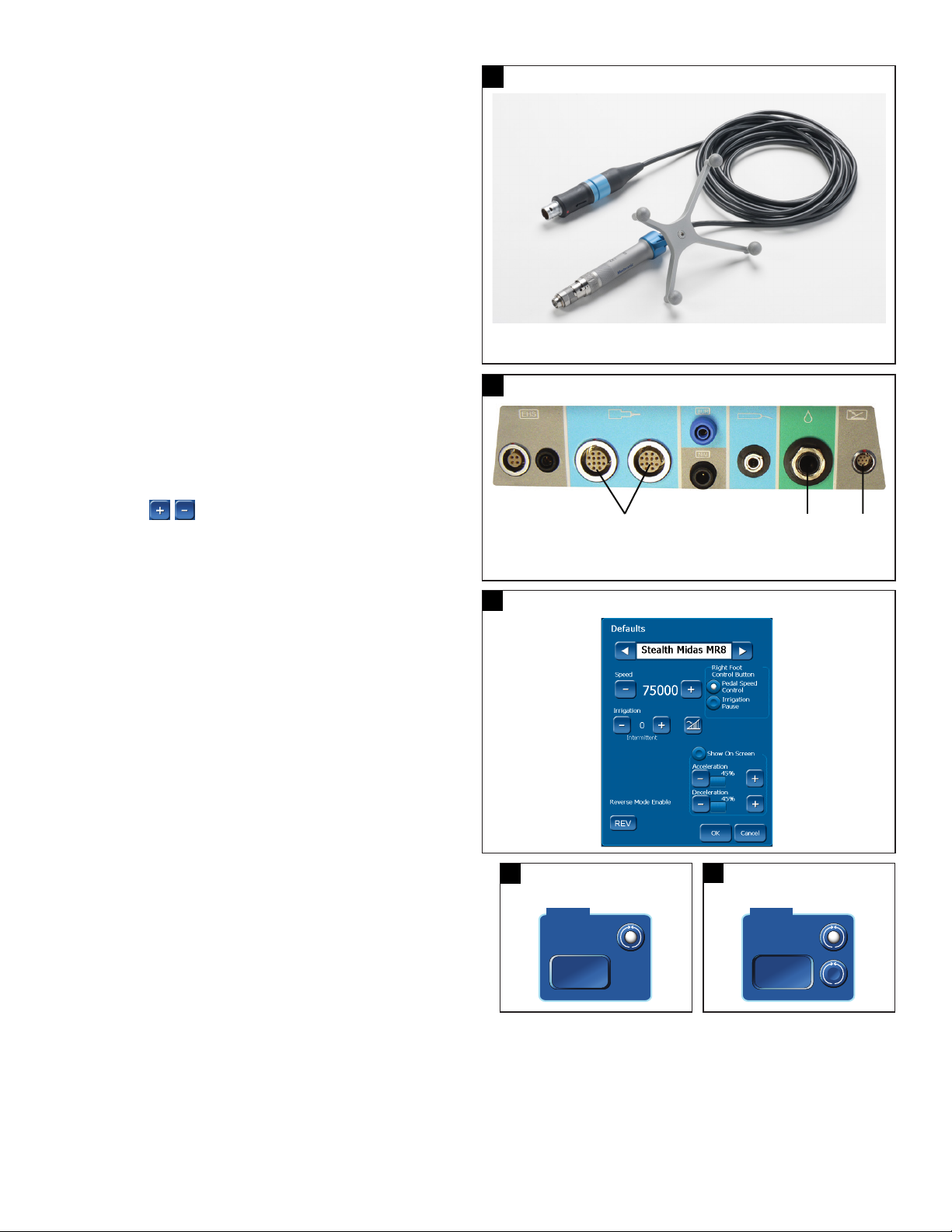
Components
The Electric Stealth-Midas MR8 motor (Figure 1) is a high speed, high torque,
navigable electric motor used to dissect bone and biomaterial at selectable
speeds from 200 to 75,000 rpm.
The following instructions for the Electric Stealth-Midas MR8 are in addition to the
general assembly instructions found in the IPC instructions for use. Complete IPC
setup, then continue to the instruction below.
IPC set up
The following instructions for the electric MR8 motors are in addition to the
general assembly instructions found in the Integrated Power Console User’s
Guide. To obtain a copy of the IPC User’s Guide, please contact Medtronic or
your local distributor.
Use an IPC device that has software version V2.7.3.0 or later, or update the
IPC device to the latest software by contacting your Medtronic Neurosurgery
Group sales representative. If outside the USA, contact your Medtronic regional
distributor or Medtronic Neurosurgery Group sales representative.
Connection to IPC
Locate the Electric Stealth-Midas MR8 connection port on the IPC connector
panel (Figure 2) and insert the connector.
Note: Refer to IPC User’s Guide for setup and more detailed instructions on
operation of IPC and touchscreen.
IPC touchscreen controls
To set or adjust the Stealth-Midas MR8 motor controls, on the IPC touchscreen
(Figure 3), in the control box, do the following:
Speed
• To adjust speed in Forward (FWD) or Reverse (REV) mode, in the Speed
control box, press the plus button to increase speed or the minus button to
decrease speed.
Irrigation
• To adjust the irrigation ow rate, in the Pump control box, press the plus button
to increase ow rate or the minus button to decrease ow rate. If intermittent
ow is available, pressing the plus or minus button progresses the system
through intermittent and continuous ow. The system displays Intermittent
when in intermittent ow mode.
Note: To adjust ow rate, you can use the touchscreen or the IntelliFlow
irrigation remote control.
• Default, 0cc per minute in Forward or Reverse mode
• For additional instructions see the IPC User’s Guide.
Acceleration and deceleration
• To adjust acceleration and deceleration, on the Defaults menu (Figure 3), press
the corresponding plus or minus button. Acceleration is the rate at which the
motor speeds up to reach the target speed. Deceleration is the rate at which
the motor slows down to reach the target speed or stop.
Note: While in the default menu, the motor will not be active to demonstrate the
selected acceleration and deceleration. To determine the desired values, adjust the
acceleration and deceleration during motor operation and note the preferred values.
• To enable adjustment of acceleration or deceleration during motor operation
and to display the acceleration and deceleration adjustment options on the
motor operational screen; On the Defaults menu, select Show On Screen
and then press [OK]. To hide the acceleration and deceleration during motor
operation, on the Defaults menu, deselect Show On Screen.
1
Electric Stealth-Midas MR8
1
5
1. IPC connection
2. Cable
2
1. Electric Stealth-Midas MR8 motor
2. Intelliow irrigation remote control
3. Foot control unit
3
4
IPC Connector Panel
Stealth-Midas MR8 touchscreen
3
3. Tracker
4. Secondary lock
2
5. Collet
Rotation (FWD and REV)
• To change rotation mode, in the Mode control box, select FWD (forward) or
REV (reverse).
Important: System conguration may be dierent from the default. If the REV
(reverse) button appears raised (Figure 4-1) and does not have a selectable radio
button, you cannot select the Reverse mode. If the REV button appears concave
(Figure 4-2) and has a selectable radio button, you can select the Reverse mode
via the touchscreen or the multifunction foot control unit.
• Conrm rotational direction on the IPC display prior to running a nger/foot
control system check.
4
4-1
REV button raised
IPC touchscreen
FWD
REV
4-2
IPC touchscreen
REV button concave
FWD
REV
Page 11
Electric Stealth-Midas™ MR8™ System
2
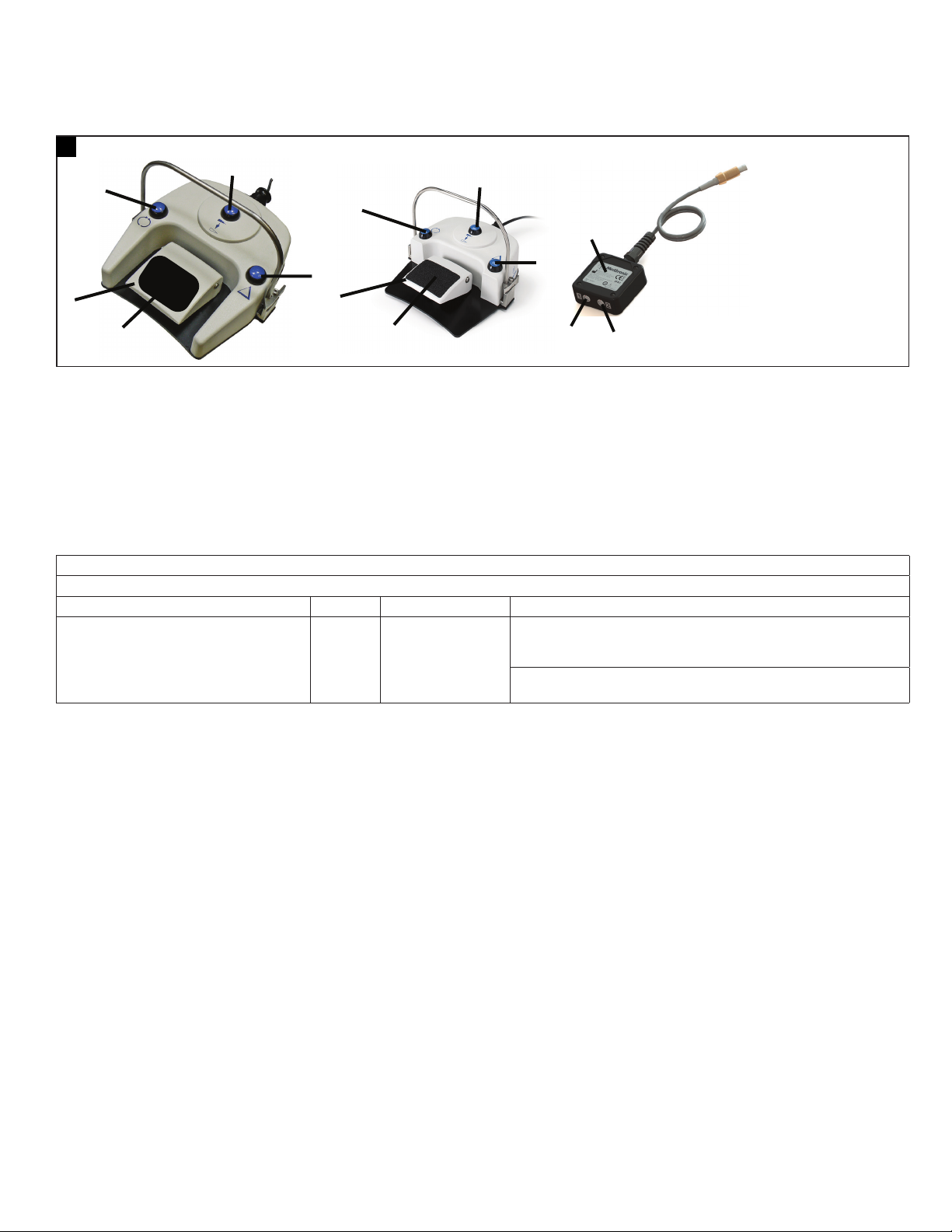
Multifunction foot control unit
Note: Conduct a system check by pressing the foot control unit to briey run the motor and conrm proper function prior to any procedure.
Important: By default, press each button on the foot control unit for at least 100 mS for the selection to become active. Use the IPC touchscreen settings screen to
change the default value.
5
Multifunction foot control unit and y-splitter
1
1
3
5
4
To use the multifunction foot control unit (Figure 5) to control the motor, do the following:
• To select Forward or Reverse mode, press the mode button (Figure 5, Number 1).
• To start or adjust the speed of a motor in variable mode, press the foot control unit (Figure 5, Number 5).
• To toggle between the start/stop mode and variable speed mode, press the control button (Figure 5, Number 3).
Note: Functionality of the control button may be changed in the motor Defaults menu to pause irrigation. Refer to Change System Settings in the Pre-Operating
Instructions section of the IPC User’s Guide.
• To change the motor, press the motor button (Figure 5, Number 2).
Cleaning the multifunction foot control unit
For cleaning instructions refer to the section, Clean the multifunction foot control unit, in the Cleaning and sterilization section of the IPC User’s Guide.
5
4
2
1. Mode button
6
3
7
8
2. Motor button
3. Control button
4. Slip-resistant food pad
5. Foot control unit
6. Y-splitter
7. Port 1
8. Port 2
Technical specications
Table 1: MR8 electric touch technical specications
Electric Stealth-Midas MR8 motor (EM800N)
Size Weight Speed Duty cycle for applied part
Length: 16.5 cm x Diameter: 1.65 cm 130 grams 75,000 rpm forward/
reverse
For use in operating room temperatures up to 40°C (104°F), the Electric
Stealth-Midas MR8 motor is rated for 3 minutes at 75,000 rpm followed by
25 minutes of rest.
For normal operating room temperatures (typically 20°C/68°F), the Electric
Stealth-Midas MR8 motor is rated for cutting indenitely at 75,000 rpm.
5
Page 12

Electric Stealth-Midas™ MR8™ System
Guidance and manufacturer’s declaration - electrical safety EMC (electromagnetic compatibility)
Functional standards for electrical systems
ANSI/AAMI ES60601-1 Medical electrical equipment - Part 1: General requirements for basic safety and essential performance
IEC 60601-1 Medical electrical equipment - Part 1: General requirements for basic safety and essential performance
EN 60601-1 Medical electrical equipment - Part 1: General requirements for basic safety and essential performance
IEC 60601-1-4 Medical electrical equipment - Part 1: General requirements for safety, Part 4: Programmable electrical medical systems
IEC 60601-1-2 Medical electrical equipment - Part 1-2: General requirements for safety, collateral standard: electromagnetic compatibility - requirements and tests
CAN/CSA
C22.2#60601-1
Environment of intended use:
• Professional healthcare facility environment
Part-1: Electromagnetic immunity
The IPC system is intended for use in the electromagnetic environment specied below. The customer or the user of the IPC system should assure that it is used in
such an environment.
Immunity test Test level (IEC/EN 60601-1-2) Compliance level Electromagnetic environment – guidance
Electrostatic discharge (ESD)
IEC 61000-4-2
Electrical fast transient/burst
IEC 61000-4-4
Surge
IEC 61000-4-5
Voltage dips, short
interruptions and voltage
variations on power supply
input lines
IEC 61000-4-11
Power frequency (50/60 Hz)
magnetic eld IEC 61000-4-8
Note:
1. UT is the mains voltage prior to application of the test level.
2. When the console is powered and connected to the foot switch, application of -15KV air discharge onto the foot switch buttons may cause the console to
freeze. Power cycle the console to re-establish normal operation.
3. The MR8 electric motor is compliant with IEC/EN60601-1-2, ed. 3.0 and ed. 4.0 standards. Refer to the IPC User’s Guide to determine specic standard
compliance for the system.
2005, CORR. 1:2009, AMMEND. 1:2012
2005, CORR. 1:2006, CORR. 2:2007, AMMEND. 1:2012
2006, AMMEND. 12:2014
1996, AMMEND. 1:1999
ED. 3.0:2007, ED. 4.0:2014
Medical electrical equipment - Part 1: General requirements for safety
ED. 3.0:2014
± 8 kV contact
± 15 kV air
± 2 kV for power supply lines
± 1 kV for input/output lines
±1 kV line to line
±2 kV line to earth
0 % UT (100 % dip in UT)
for 0.5 cycle at 0°, 45°, 90°, 135°,
180°, 225°, 270°, and 315°
0 % UT (100 % dip in UT)
for 1 cycle at 0°
40 % UT (60 % dip in UT)
for 5 cycles
70 % UT (30 % dip in UT)
for 0.5 sec
0 % UT (100 % dip in UT)
for 5 sec
30 A/m 30 A/m Power frequency magnetic elds should be at levels characteristic
± 8 kV contact
± 15 kV air
± 2 kV for power supply lines
± 1 kV for input/output lines
±1 kV line to line
±2 kV line to earth
0 % UT (100 % dip in UT)
for 0.5 cycle at 0°, 45°, 90°, 135°,
180°, 225°, 270°, and 315°
0 % UT (100 % dip in UT)
for 1 cycle at 0°
40 % UT (60 % dip in UT)
for 5 cycles
70 % UT (30 % dip in UT)
for 0.5 sec
0 % UT (100 % dip in UT)
for 5 sec
The relative humidity should be at least 5%.
Note 1 and 3
Mains power quality should be that of a typical commercial or
hospital environment.
Mains power quality should be that of a typical commercial or
hospital environment.
Mains power quality should be that of a typical commercial
or hospital environment. If the user of the IPC system requires
continued operation during power mains interruptions, it
is recommended that the IPC system be powered from a
uninterruptible power supply or a battery.
of a typical location in a typical commercial or hospital environment
Part-1: Electromagnetic emissions
The IPC system is intended for use in the electromagnetic environment specied below. The customer or the user of the IPC system should assure that it is used in
such an environment.
Emissions test Compliance Electromagnetic environment – guidance
RF emission
CISPR 11
RF emission
CISPR 11
Harmonic emissions
IEC 61000-3-2
Voltage uctuations/icker emissions
IEC 61000-3-3
6
Group 1 The IPC system uses RF energy only for its internal function. Therefore, its RF
Class A The IPC system is suitable for use in all establishments, other than domestic
Class A
Complies
emissions are very low and are not likely to cause any interference in nearby
electronic equipment.
and those directly connected to the public low-voltage power supply
network that supplies buildings for domestic purpose.
Page 13

Electric Stealth-Midas™ MR8™ System
Recommended separation distances between portable and mobile RF communications equipment and the MR8 system
The IPC system is intended for use in an electromagnetic environment in which radiated RF disturbances are controlled. The customer or the user of the IPC system
can help prevent electromagnetic interference by maintaining a minimum distance between portable and mobile RF communications equipment (transmitters)
and the IPC system as recommended below, according to the maximum output power of the communications equipment.
Rated maximum
power of transmitter
W
0.01 0.03 0.03 0.07 0.03 0.03 0.03 0.07
0.1 0.07 0.07 0.21 0.07 0.07 0.07 0.21
1 0.22 0.22 0.67 0.22 0.22 0.22 0.67
10 0.7 0.7 2.12 0.7 0.7 0.7 2.12
100 2.2 2.2 6.7 2.2 2.2 2.2 6.7
For transmitters rated at a maximum output power not listed above, the recommended separation distance d in meters (m) can be determined using the equation
applicable to the frequency of the transmitter, where P is the maximum output power rating of the transmitter in watts (W) according to the transmitter manufacturer.
Note: These guidelines may not apply in all situations. Electromagnetic propagation is aected by absorption and reection from structures, objects and people.
Separation distance (in meters) according to frequency of transmitter
380MHz-390MHz
d = 0.22√P
430MHz-470MHz
d = 0.22√P
704MHz-787MHz
d = 0.67√P
800MHz-960MHz
d = 0.22√P
1.7GHz-1.99GHz
d = 0.22√P
2.4GHz-2.57GHz
d = 0.22√P
5.1GHz-5.8GHz
d = 0.67√P
Part-2: Guidance and manufacturer’s declaration – electromagnetic immunities
The IPC system is intended for use in the electromagnetic environment specied below. The customer or the user of the IPC system should assure that it is used in
such an environment.
Immunity test Test level (IEC/EN 60601-1-2) Compliance level Electromagnetic environment - guidance
Conducted RF
IEC 61000-4-6
Radiated RF
IEC 61000-4-3
3 Vrms
150 kHz to 80 MHz
6 Vrms
150 kHz to 80 MHz in ISM bands
and amateur radio bands
3 V/m
80 MHz to 2.7 GHz
9 – 28 V/m
Spot frequencies
385MHz to 5.785 GHz
Pulse modulation
3 Vrms
150 kHz to 80 MHz
6 Vrms
150 kHz to 80 MHz in ISM bands
and amateur radio bands
3 V/m
80 MHz to 2.7 GHz
9 – 28 V/m
Spot frequencies
385MHz to 5.785 GHz
Pulse modulation
Portable RF communications equipment (including peripherals such as
antenna cables and external antennas) should be used no closer than 30
cm (12 inches) to any part of the IPC system, including cables specied
by the manufacturer. Otherwise, degradation of the performance of this
equipment may result.
Portable and mobile RF communications equipment should be used
no closer to any part of the IPC system including cables, than the
recommended separation distance calculated from the equation
applicable to the frequency of the transmitter.
Recommended separation distance:
6
d P
E
Where P is the maximum output power rating of the transmitter in watts
(W) according to the transmitter manufacturer, E is the immunity test
levels in volt per meter (V/m), and d is the recommended separation
distance in meters (m).
Interference may occur in the vicinity of equipment marked with the
following symbol:
Note: These guidelines may not apply in all situations. Electromagnetic propagation is aected by absorption and reection from structures, objects and people.
7
Page 14

Electric Stealth-Midas™ MR8™ System
MR8 dissecting tools and attachments
Straight attachment assembly
Warning: Match the nomenclature and color code on the tool packaging to the same nomenclature and color code on the attachment. Conrm that the dissecting
tool packaging label has the Stealth-Midas MR8 logo ( ) if navigation is required.
Notes:
• Prior to installation of an attachment and dissecting tool, ensure that the arrows on the motor collet ats are aligned. If the arrows are not aligned, use the motor
wrench to turn the collet at closest to the motor case until its arrow is aligned with the arrow on the other collet at.
• The MR8 motors will not operate if the attachment is not in the fully locked position.
1. Slide a straight attachment over the motor collet aligning triangular arrows on the attachment and the motor case (Figure 6). An audible click, heard and
perceptible by touch, conrms that the attachment is fully seated.
2. Inser t the tool into the attachment with a slight rotational motion (Figure 7). An audible click, heard and perceptible to the touch, conrms that the tool is fully seated.
6
3. To lock the attachment, rotate the attachment in the direction indicated by arrow on the attachment until the attachment alignment mark is directly in line with
the locked symbol (Figure 8).
Note: You will hear an audible click as the attachment is rotated to the locked position.
4. Gently pull on the tool to ensure that it is locked into the motor.
Note: Tool should rotate freely. If not, unlock the attachment, re-seat the tool, and re-lock the attachment.
5. To rotate the secondary lock to the locked position, rotate the secondary lock collar marked with “NAV” in the direction of the arrow to achieve a snug connection
between attachment and motor (Figure 9). Apply enough rotational torque so that a solid connection is attained. The secondary lock should become fully
engaged after ¼ turn. Once fully engaged, the arrow head on the “NAV” locking ring will be in proximity to the lock symbol on the motor.
Note: This secondary lock is required to eliminate motion between the attachment and the motor, which could impact navigation accuracy.
8
Straight attachment assembly Insert tool
Attachment in the locked position Locking the secondary lock
7
9
Straight attachment disassembly
1. Hold the motor in palm of hand and unlock the secondary lock by rotating it by a ¼ turn in order to bring the arrow on the “NAV” locking ring in proximity to the
unlock symbok on the motor (Figure 10).
2. Rotate the attachment to the unlocked position. The arrows in the attachment and motor will line up by the unlock symbol as in (Figure 11).
Note: If using a DK attachment, push the attachment distally before rotating.
3. Remove the dissecting tool from the attachment and discard the tool.
4. Use thumb and index nger to pull the attachment o the motor.
10
8
Straight attachment disassembly: Unlock the secondary lock The arrows in the attachment and motor will line up by the unlock symbol
11
Page 15

Electric Stealth-Midas™ MR8™ System
Angled attachment assembly
1. With the attachment tool lock in the unlocked position, insert a dissecting tool into the angled attachment with a slight rotational motion (Figure 12). An audible
click, heard and perceptible by touch, conrms that the tool is fully seated.
2. Lock the tool by rotating the tool lock/unlock sleeve in the direction indicated by arrow until the tool lock alignment mark is directly in line with the locked
symbol (Figure 13).
12
3. Gently pull on the tool to ensure that it is locked into the motor.
Note: Tool should rotate freely. If not, unlock the attachment, re-seat the
tool, and re-lock the attachment.
4. Slide the angled attachment over the motor collet aligning the triangular
arrows on the attachment and the motor. The angled attachment will be to the
left of the motor with the motor tracker facing up (Figure 14). An audible click,
heard and perceptible by touch, conrms that the attachment is fully seated.
5. Rotate the attachment in the direction indicated by the arrow until the
attachment alignment mark is directly in line with the locked symbol. You will
hear an audible click as the attachment is rotated to the locked position.
6. Verify that both the attachment to motor alignment mark and the tool lock alignment mark are directly in line with the locked symbols (Figure 15).
7. To rotate the secondary lock to the locked position, rotate the secondary lock collar marked with “NAV” in the direction of the arrow to achieve a snug
connection between attachment and motor (Figure 16). Apply enough rotational torque so that a solid connection is attained. The secondary lock should
become fully engaged after ¼ turn. Once fully engaged, the arrow head on the “NAV” locking ring will be in proximity to the lock symbol on the motor.
Notes:
• This secondary lock is required to eliminate motion between the attachment and the motor, which could impact navigation accuracy.
• Navigation is enabled for angled attachments in the down orientation.
15
Angled attachment assembly: Tool/attachment lock to motor Secondary lock tightens attachment to motor
Angled attachment assembly: Insert tool Angled attachment assembly: Rotate tool lock
14
13
Angled attachment assembly: Motor tracker facing up
16
Angled attachment disassembly
1. Rotate the attachment tool lock to the unlocked position to remove the tool
from the angled attachment.
2. Remove the dissecting tool from the attachment and discard the tool.
3. Hold the motor in palm of hand and unlock the secondary lock by rotating it
by a ¼ turn in order to bring the arrow on the “NAV” locking ring in proximity
to the unlock symbok on the motor.
4. Rotate the attachment to the unlocked position. The arrows in the attachment
and motor will line up by the unlock symbol as in Figure 17.
Note: If using a DK attachment, push the attachment distally before rotating.
5. Use thumb and index nger to remove the angled attachment from the motor.
17
Unlocked position of the angled attachment
9
Page 16

Electric Stealth-Midas™ MR8™ System
ClearView tool assembly
Note: Refer to the ClearView tools Instructions for Use for more information.
1. Slide the ClearView tool over the motor collet aligning triangular arrows on the tool hub and the motor (Figure 18). In the unlocked position, the ClearView tool is
facing to the left relative to the tracker.
2. To lock the ClearView tool, rotate the attachment in the direction indicated by the arrow until attachment alignment mark is directly in line with the locked
symbol. You will hear an audible click as the attachment is rotated to the locked position (Figure 19).
18
3. Rotate the secondary lock collar marked with “NAV” in the direction of the arrow to achieve a snug connection between attachment and motor (Figure 20). Apply
enough rotational torque so that a solid connection is attained. The secondary lock should become fully engaged after ¼ turn. Once fully engaged, the arrow
head on the “NAV” locking ring will be in proximity to the lock symbol on the motor.
Notes:
• This secondary lock is required to eliminate motion between the ClearView tool and the motor, which could impact navigation accuracy.
• Navigation is enabled for the ClearView tools in the down orientation. Navigation is also enabled in the up orientation for the trans nasal burrs
(ND13BA30DC and ND13BA40DC).
4. Attach irrigation tubing to the ClearView tool irrigation hub (Figure 21).
20
Unlocked position of ClearView tool Locked position of ClearView tool
Secondary lock attachment to motor ClearView tool with irrigation tubing attached
19
21
ClearView tool disassembly
1. Remove irrigation tubing.
2. Hold the motor in palm of hand and unlock the secondary lock by rotating it by a ¼ turn in order to bring the arrow on the “NAV” locking ring in proximity to the
unlock symbol on the motor (Figure 22).
3. Rotate the attachment to the unlocked position. The arrows in the attachment and motor will line up by the unlock symbol as in Figure 23.
4. Use thumb and index nger to pull the ClearView tool o the motor.
22
Unlock the secondary lock ClearView tool in the unlocked position
23
10
Page 17

Electric Stealth-Midas™ MR8™ System
Navigable dissecting tools and attachments
24
Midas tool sample label with Stealth-Midas MR8 logo
Note: Refer to the Midas Rex MR8 electric high speed drill system Instructions
for Use for information on tool nomenclature and attachment details.
Dissecting tools
Use only dissecting tools specically designed for use with this drill system.
Conrm that the dissecting tool packaging label has the Stealth-Midas MR8
logo ( ) if navigation is required (Figure 24).
Attachments
The Stealth-Midas MR8 is compatible with MR8 attachment types that
correspond to a navigable tool: straight, angled, variable, or double-locking.
Note: The location of the tool head (tip) relative to the tracker does not
change when the tool exposure changes.
Sterile sphere assembly
Open sterile spheres package. One pack is a set of ve. Place single-use sterile spheres on each of the
tracker’s four posts (Figure 25). Press on each sterile sphere onto the stem until they “snap” into place.
Ensure the sterile spheres are rmly seated on the posts, clean and dry before navigating.
Navigation
Once the sterile spheres are assembled the product can be optically tracked by the StealthStation S8.
Refer to the S8 Spine and Cranial Software Pocket Guides for further instructions on selection of
instrument tool cards, verication, and navigation of the Stealth-Midas MR8.
Troubleshooting
Issue Possible Cause Action
25
Sterile sphere assembly
Motor is too hot to touch/hold Inadequate cool down period following sterilization Motor must be allowed to cool down following steam sterilization.
Attachment is transferring heat to the motor Switch attachments to determine whether the heat is being generated by the motor
Heavy side loading during dissection Discontinue use and rest the motor by using it intermittently or wrap the motor with
Tool is dicult to remove from
attachment
Attachment will not seat properly on
the motor
Motor does not run Cables not properly connected Ensure motor and foot control cables are properly connected.
Motor with attachment rotates, but an
abnormal noise is heard
ClearView tool or irrigation does not
run properly
Aging of attachment Contact Customer Service.
Use of reprocessed tools
Use of an unauthorized refurbisher
Improper cleaning Clean the attchment thoroughly according to the instructions in this manual.
Motor collet ats are not aligned Use the Stealth-Midas MR8 motor wrench to rotate the at closest to the motor case
Speed setting is too low Ensure that a speed greater than 3000 rpm is selected. Check the IPC for error status.
Attachment not properly installed and locked onto
the motor
Internal failure of motor and/or console Change motor or console to isolate the problem.
Foot control not properly functioning Check for obstruction under the foot control unit.
Cables damaged Check cable for cracks, splits, or bent connector pins.
Bearings are worn Change the attachment to isolate the location of the problem.
Poor electrical connection Check all connections from the electrical source to console.
Internal failure of motor, console, or cable Change motor or console to isolate the failing component.
Attachment not properly installed Remove and reinstall the attachment and dissecting tool.
or the attachment.
a moist sterile towel.
Change tool.
until its marker is aligned with the marker on the at farthest away from the motor case.
Remove and reinstall the attachment and dissecting tool to ensure proper installation.
Ensure motor and foot control cables are properly connected.
Refer to Midas Rex ClearView User’s Guide.
System does not navigate Non-navigated dissecting tool selected on packaging Ensure tool has the Stealth-Midas MR8 logo.
*For navigation troubleshooting, consult
the StealthStation S8 Pocket Guide and
StealthStation S8 System Manual
Angled attachment not in fully locked position Conrm that the attachment to motor lock and secondary lock are both secure.
Incorrect Angled Attachment orientation Conrm angled attachment tool faces away from tracker.
11
Page 18

Electric Stealth-Midas™ MR8™ System
System accessories: disposable components
Cleaning brushes
Clean debris from lumen of attachments with the appropriate cleaning brushes.
The disposable cleaning brushes are sized for Stealth-Midas MR8
attachments, but they will not pass through the angled attachments,
because they are not cannulated.
Table 2: Disposable cleaning brush dimensions
Internal bore diameter Brush length
1.2 mm 20 cm (8 in)
2.4 mm 41 cm (16 in)
3.2 mm 41 cm (16 in)
System accessories: non-disposable components
Instrument tray
The 3/4 DIN CA875 instrument tray holds the Stealth-Midas MR8 motor and attachments (Figures 26-27) to be sterilized and is placed inside the rigid sterilization
container or wrapped for steam sterilization.
26
3/4 DIN CA875 instrument tray closed 3/4 DIN CA875 instrument tray upper level with attachments
27
Rigid sterilization container (sterilization case)
The rigid sterilization container is a sterilization containment device designed
to hold the Stealth-Midas MR8 system equipment for sterilization, storage,
transportation, and aseptic presentation of its contents (Figure 28). This case is
available in a 3/4 DIN size.
The system consists of a base with carrying handles and lid that is secured to
the base by means of a latching mechanism. The instrument tray holds StealthMidas MR8 attachments and/or other Stealth-Midas MR8 system equipment to
be sterilized and is placed inside the rigid sterilization container. A lter system
is incorporated to provide for air evacuation and sterilant penetration during
the sterilization cycle and to act as a barrier to microorganisms during storage,
handling, and transport.
28
3/4 DIN rigid sterilization container
12
Page 19

Electric Stealth-Midas™ MR8™ System
Electric Stealth-Midas MR8 system reprocessing instructions
Cleaning is the removal of organic soil. Eective cleaning:
• Minimizes the organic soil transfer from one patient to another.
• Prevents accumulation of residual soil throughout the device’s useful life.
• Allows for successful follow-up sterilization. Adequate reprocessing is contingent upon the thoroughness of cleaning.
Cleaning is the initial step. Sterilization occurs later in reprocessing and is intended to kill microorganisms to reduce the likelihood of transmission and possibilities of
infection. To ensure acceptable reprocessing, there should be no delay between the cleaning, inspection, and sterilization.
Blood-borne pathogens - Universal precautions for handling this device after use should be observed by all hospital personnel according to OSHA standard 29 CFR
1910.1030, occupational exposure to blood-borne pathogens.
Warnings and
cautions
Limitations on
reprocessing
Point of use Reprocessing begins at the point of use.
Containment and
transportation
Preparation for
cleaning: automated
• Do not remove tracker from the motor.
• Remove navigation spheres from tracker and discard before cleaning and sterilization.
• Do not soak or submerge electric Stealth-Midas MR8 system devices.
• Do not use ultrasonic cleaners for electric Stealth-Midas MR8 system devices.
• Do not use chlorine-based or corrosive cleaning agents such as bleach, lye, acetone, sodium hypochlorite or bleach, sodium
hydroxide, formic acid, or solutions containing glutaraldehyde.
• Use only nylon cleaning brushes. Non-nylon cleaning brushes leave residue that may prevent the tool from being secured properly
in the motor.
Note: Attachments may be disposed of at the end of their useful life according to local and national regulations. Due to safety and
environmental concerns, Medtronic requests the return of Stealth-Midas electric high speed motors for proper disposal at the end of the
product useful life.
End of useful life is normally determined by wear and damage due to use.
See the “Maintenance, inspection, and testing” section in this document to determine if the device is at its end of useful life.
Do not allow blood, debris, or bodily uids to dry on the device. Remove excess soil using running, cold tap water 10 - 22°C (50 - 72°F).
Tap water is dened as potable water with hardness value between 0.7 mmol/l to 2.0 mmol/l.
Caution: Devices should be cleaned within 30 minutes of use to limit xation of contaminants.
Do not place soiled instruments into the instrument case. Transport used devices in a separate container.
If the device cannot be reprocessed immediately, keep the device moist during transport.
It is recommended that devices are reprocessed as soon as is practical following use.
To prolong the life of the device, reprocess immediately after use.
Stealth-Midas MR8 electric motor:
• Do not remove tracker from the motor. Tracker is permanently axed.
• Ensure that the attachment, tube, and dissecting tool have been removed from the motor prior to cleaning.
• Remove Navigation spheres from the tracker and discard.
• With collet end and cable connector ends pointed down, manually rinse the motor under cold running tap water (10 - 22°C / 50 - 72°F)
to remove any visible soil.
• Use a nylon brush to aid in cleaning.
• Give particular attention to crevices and other areas that present a challenge to cleaning.
• Remove devices from instrument trays before placing into washer.
• Orient devices following recommendations of the washer/disinfector manufacturer.
• Clean per recommended washer cycle per Table 3 or Table 4.
• After cleaning, visually examine the devices for cleanliness. If visible soil remains, repeat cleaning.
MR8 attachments:
• Do not remove tracker from the motor. Tracker is permanently axed
• Ensure that the attachment, tube, and dissecting tool have been removed from the motor prior to cleaning.
• Rinse attachments under cold running tap water (10 - 22°C / 50 - 72°F) to remove any visible soil.
• Use a nylon brush to aid in cleaning.
• Give particular attention to crevices and other areas that present a challenge to cleaning.
• Attachments with moving parts should be actuated through their full range of motion under cold running tap water.
• While rinsing under cold running tap water, use an appropriately sized (refer to Table 2) nylon lumen brush internally to aid in
cleaning attachments.
• Variable exposure attachments (AVAXX, AVAXXDK, AVSXX) must be placed in the washer with their tube in the fully extended position.
• Orient devices following recommendations of the washer/disinfector manufacturer.
• Clean per recommended washer cycle per Table 3 or Table 4.
• After cleaning, visually examine all parts of the device for cleanliness. If visible soil remains, repeat cleaning.
Instrument tray:
• To clean the instrument tray after use, thoroughly rinse the instrument tray under cold running tap water to remove any visible soil.
• Use a soft-bristled brush or clean cloth to aid soil removal around brackets and handles.
• Give particular attention to crevices and other areas that present a challenge to cleaning.
• Carefully inspect trays, handles, instrument brackets, and cavities to ensure all visible soil is removed.
• Clean per recommended washer cycle per Table 3 or Table 4.
• After cleaning, visually examine the instrument tray for cleanliness. If visible soil remains, repeat cleaning.
13
Page 20

Electric Stealth-Midas™ MR8™ System
Rigid sterilization container:
• To clean the sterilization container after use, discard the single use lters and thoroughly rinse the sterilization container under cold
running tap water to remove any visible soil.
• Use a soft-bristled brush or clean cloth to aid soil removal around brackets, lter retention plates, and handles.
• Gently ush the gasket region of the sterilization container if soil is visible.
• Give particular attention to crevices and other areas that present a challenge to cleaning.
• Carefully inspect containers, handles, gaskets, lter retention plates, instrument brackets, and cavities to ensure all visible soil is removed.
• Remove the lter retention plates from the lid and base by turning the lever on the retention plate clockwise. Do not remove the
gasket for the cleaning procedure.
• Clean per recommended washer cycle per Table 3 or Table 4.
• After cleaning, visually examine the sterilization container for cleanliness. If visible soil remains, repeat cleaning.
Cleaning: automated Warnings:
• Use the instrument tray and the rigid sterilization container for sterilizing the re-usable devices only.
• Do not use the instrument tray and sterilization container for cleaning or disinfection of the re-usable devices.
• Do not use alkaline cleaning for the instrument tray or the rigid sterilization container.
Cautions:
• Do not use ultrasonic cleaner.
Table 3: Neutral Wash Cycle Parameters
MR8 motors, attachments and tubes, and instrument tray - neutral
Phase Recirculation/soak
Pre-wash 2 minutes (02:00) Cold tap water
Enzyme wash 2 minutes (02:00) Hot tap water
Wash 1 2 minutes (02:00) 66°C (151°F) (setpoint) Neutral pH detergent like Steris Prolystica 2x concentrate
Rinse 1 15 seconds (00:15) 43 - 60°C (109 - 140°F) Not applicable
Thermal rinse 1 minute (01:00) 90°C (194°F) (setpoint) Not applicable
Puried water rinse 10 seconds (00:10) 66°C (151°F) (setpoint) Not applicable
If visible soil remains, repeat cleaning.
Table 4: Alkaline Wash Cycle Parameters
MR8 motors, attachments and tubes – alkaline detergent (working solution pH ≤ 10.5)*
Note: Do not use alkaline cleaning for the instrument tray or the rigid sterilization container.
Phase Recirculation/soak
Pre-wash 2 minutes (02:00) Cold tap water
Wash 5 minutes (05:00) 43°C (109°F) (set point) Alkaline detergent like Dr. Weigert neodisher® MediClean forte,
Rinse 1 minute (01:00) Hot tap water
Thermal rinse 1 minute (01:00) 90°C (194°F) (setpoint) Not applicable
Puried water rinse 1 minute, 30 seconds
If visible soil remains, repeat cleaning.
*Alkaline detergent manufacturers provide alkaline detergents concentrated. The alkaline detergents must be diluted per the
detergent manufacturer’s instructions for cleaning medical devices. Medtronic has veried alkaline detergent compatibility for
working solutions up to 10.5.
After cleaning, lubricate attachments using an aerosol spray lubricant (such as Pana Spray) and perform the following steps to lubricate attachments:
1. Holding the can approximately 10-15 cm (3-6 in.) away from the attachment, spray all movable components with three quick squirts.
2. Actuate movable components to ensure proper lubrication.
3. Remove excess lubricant with a clean cloth.
(minutes)
(minutes)
(01:30)
Water temperature Detergent type
10 - 16°C (50 - 61°F)
43 - 55°C (109 - 131°F)
Water temperature Detergent type
10 - 16°C (50 - 61°F)
43 - 60°C (109 - 140°F)
66°C (151°F) (setpoint) Not applicable
Not applicable
Neutral pH enzymatic cleaner like Steris Prolystica® 2x
concentrate enzymatic cleaner, 1.0mL/L (1/8 oz/gallon)
neutral detergent, 1.0mL/L (1/8 oz/ gallon)
Not applicable
2mL/L (1/4oz/gal)
Not applicable
14
Page 21

Cleaning: manual Stealth-Midas MR8 electric motor:
• Do not remove tracker from the motor. Tracker is permanently axed
• Ensure that the attachment, tube, and dissecting tool have been removed from the motor prior to cleaning.
• Remove Navigation spheres from the tracker and discard.
• With collet end and cable connector ends pointed down, manually rinse the motor under cold running tap water (10 - 22°C / 50 - 72°F)
to remove any visible soil.
• A nylon brush may be used to aid in cleaning.
• Give particular attention to crevices and other areas that present a challenge to cleaning.
• Actuate all moving parts through their full range of motion while rinsing under running cold tap water.
• Prepare with tap water a neutral enzymatic cleaner, like Steris Prolystica 2x concentrate enzymatic cleaner, following the manufacturer’s
recommendations of 1.0 mL/L (1/8 oz/gallon) at a temperature of 23°C (73°F) or use an equivalent neutral pH cleaner following that
manufacturer’s recommendations.
• Wipe all external surfaces of the motor, cable, and cable connector with a cloth dampened with the prepared cleaner.
• Brush motor case, collet, and connector with a nylon brush dampened with the prepared cleaner.
• Rinse the device thoroughly under warm running tap water (23 - 43°C / 73 - 109°F), collet end and cable connector pointed down.
• Following the warm tap water rinse, the device should be thoroughly rinsed in room temperature 25°C (77°F) puried water
(deionized, reverse osmosis, or equivalent) for a minimum of 30 seconds with collet end and cable connector pointed down.
• Dry the entire device with lint-free towel.
• Verify that devices are visually clean after manual cleaning. If visible soil remains, repeat cleaning
Stealth-Midas MR8 electric attachments:
• Do not remove tracker from the motor. Tracker is permanently axed
• Ensure that the attachment, tube, and dissecting tool have been removed from the motor prior to cleaning.
• Thoroughly rinse the attachments under running cold tap water (10 - 22°C / 50 - 72°F) to remove any visible soil.
• A nylon brush may be used to aid in cleaning.
• Give particular attention to crevices and other areas that present a challenge to cleaning.
• Actuate all moving parts through their full range of motion while rinsing under running cold tap water.
• Prepare with tap water a neutral enzymatic cleaner, like Steris Prolystica 2x concentrate enzymatic cleaner, following the manufacturer’s
recommendations of 1.0 mL/L (1/8 oz/gallon) at a temperature of 23°C (73°F) or use an equivalent neutral pH cleaner following that
manufacturer’s recommendations.
• Wipe all attachments with a cloth dampened with the prepared cleaner.
• A nylon brush dampened with the prepared cleaner may be used to clean the external surfaces and internal connecting surfaces of
the attachment base.
• Straight attachments have special cleaning brushes sized to the attachment’s internal diameter (refer to Table 2). Push the brush wet
with the prepared cleaner through the attachment from rear to front to loosen and remove debris trapped inside.
• Other attachments may be mechanically agitated in the prepared cleaner solution but not soaked.
• For angled attachment, only place one half (e.g. tube side) of the attachment into the cleaner a time. Do not immerse the entire
attachment. Gently agitate the attachment in the cleaner and actuate any moveable parts. Then place the other half (e.g. base side)
of the attachment into the cleaner and repeat (Figure 29).
• Ensure that the tube on the angled attachment be cleaned with the appropriate sized brush (refer to Table 2).
• Actuate any moveable parts through their full range of motion to allow cleaner to thoroughly clean attachment.
• Under warm running tap water (23 - 43°C / 73 - 109°F), actuate any moveable parts through their full range of motion to allow water
to thoroughly rinse the attachment.
• Following the warm tap water rinse, the device should be thoroughly rinsed in room temperature 25°C (77°F) puried water
(deionized, reverse osmosis, or equivalent) for a minimum of 30 seconds.
• Verify that devices are visually clean after manual cleaning. If visible soil remains, repeat cleaning.
• Thoroughly dry attachments. An air gun may be used to blow moisture out from rear to front of attachment.
Electric Stealth-Midas™ MR8™ System
29
Angled attachment cleaning example
1
1. Tube/tool side 2. Base side
2
15
Page 22

Electric Stealth-Midas™ MR8™ System
Instrument tray and rigid sterilization container
1. Manually clean the rigid sterilization container and instrument tray only when a washer-disinfector is not available.
a. Thoroughly rinse the rigid sterilization container and instrument tray under cold running tap water (10 - 22°C / 50 - 72°F) to
remove any visible soil.
b. Use a soft-bristled brush or clean cloth to aid soil removal around brackets, handles, and lter retention plates (only on the rigid
sterilization container).
c. If soil is visible, gently ush the gasket region of the rigid sterilization container.
d. Give particular attention to crevices and other areas that present a challenge to cleaning.
e. Carefully inspect the rigid sterilization container and instrument tray, including the handles, gaskets, lter retention plates, and
cavities, to ensure all visible soil is removed.
2. Prepare neutral enzymatic cleaner Steris Prolystica 2x Concentrate.
a. Prepare the enzymatic cleaner following the manufacturer’s recommendations of 1.0ml/L (1/8 oz/gallon) at a temperature of 23°C (73°F)
or use an equivalent neutral pH cleaner following that manufacturer’s recommendations.
b. Immerse the rigid sterilization container and instrument tray in the prepared enzymatic cleaner, actuate the tray and allow it to
soak for a minimum of 10 minutes.
3. Thoroughly clean the rigid sterilization container and instrument tray.
a. Use a soft-bristled brush for the outer portion of the rigid sterilization container and instrument tray.
b. Pay particular attention to crevices, lter retention plates (only on the rigid sterilization container), latches, and other hard-to-
clean areas to remove all visible soil.
4. After soaking, thoroughly rinse the rigid sterilization container and instrument tray under warm (23 - 43°C / 73 - 109°F) running tap
water for a minimum of 1 minute to remove all residual cleaner.
a. Rinse the rigid sterilization container and instrument tray.
b. Use a syringe to aid in rinsing.
5. Following the warm tap water rinse, thoroughly rinse the rigid sterilization container and instrument tray in room temperature
25°C (77°F) puried water (deionized, reverse osmosis, or equivalent) water for a minimum of 30 seconds.
Note: After cleaning, visually examine all parts of the rigid sterilization container and instrument tray for cleanliness. If visible soil
remains, repeat cleaning.
6. Dry the instrument tray and rigid sterilization container with a clean, lint-free towel.
After cleaning, lubricate attachments using an aerosol spray lubricant (such as Pana Spray) and perform the following steps to lubricate
attachments:
1. Holding the can approximately 10-15 cm (3-6 in.) away from the attachment, spray all movable components with three quick squirts.
2. Actuate movable components to ensure proper lubrication.
3. Remove excess lubricant with a clean cloth.
Disinfection No particular requirements.
Drying If necessary, dry the devices with a clean, lint-free towel. Refer to the motor, attachment/tube, instrument tray, and sterilization container
Maintenance,
inspection, and
testing
cleaning sections on specic drying instructions.
Do not reprocess for surgical use a device that has obvious damage or corrosion. Return to Medtronic for service.
Visually inspect the reprocessed devices following cleaning. Inspection should be performed with adequate lighting. Magnication is not
required. A device that shows or exhibits the properties listed below is at the end of its useful life. Attachments and telescoping tubes
may be disposed of at the end of their useful life according to local and national regulations. Due to safety and environmental concerns,
Medtronic requests the return of Stealth-Midas electric high speed motors for proper disposal at the end of the product’s useful life.
• Obvious damage or corrosion
• Pitting, cracks, fractures, or bending
• Illegible laser etchings, engravings, and other markings
• Discoloration, corrosion, stains, or rust.
• Mechanisms that are rough or stuck. These are indications of bad O-rings or damaged internal components, for example, variable
exposure collars, tool lock collar, and sleeves.
16
Page 23

Packaging Warnings:
• Do not load more than one Stealth-Midas MR8 electric motor inside the instrument tray per sterilization cycle.
• Do not wrap the rigid sterilization container.
• Use the instrument tray and the rigid sterilization container for sterilization only. The MR8 system devices must be cleaned separate
from the trays.
There are two options available for packaging:
1. Devices may be sterilized using a wrapped instrument tray. The instrument tray should be wrapped with two layers of 1-ply
polypropylene wrap using a sequential envelope technique. For use in the USA, an FDA-cleared wrap should be used.
2. Devices can also be sterilized by placing them inside the 3/4 DIN CA875 instrument tray and then placing the 3/4 DIN CA875
instrument tray inside the 3/4 DIN rigid sterilization container.
Instrument tray:
1. Inspect the following components before each sterilization cycle. Make sure the instrument tray does not have cracks or tears and
that the silicone brackets (Figure 30) are not damaged.
30
Silicone brackets
2. Arrange the cleaned devices in the instrument tray’s silicone brackets. The instrument tray includes printed outlines as a guide for
the devices that t within the tray.
3. Variable exposure attachments (AVAXX, AVAXXDK, AVSXX) must be placed in the instrument tray with their tube in the fully
extended position (Figure 31).
4. Ensure the the navigation spheres are removed from the tracker and discard.
5. Place the motor inside the instrument tray as shown in Figure 32.
6. Close the instrument tray with the lid.
Electric Stealth-Midas™ MR8™ System
31
Instrument tray with variable
exposure attachments
32
Placement of the motor in the
3/4 DIN CA875 instrument tray lower level
1
1. Variable exposure attachment in the fully extended position
Option 1: Wrap the instrument tray for sterilization:
• The user facility is responsible for using only accessories (such as sterilization wraps, chemical indicators, and biological indicators) that are
cleared and labeled for the validated sterilization parameters specied in this Instructions for Use by the Food and Drug Administration for
medical facilities in the U.S.A. and its territories, or conform to EN ISO 11607 for medical facilities outside of the U.S.A. and its territories.
• The instrument tray should be wrapped with two layers of 1-ply polypropylene wrap using a sequential envelope technique. For use
in the USA, an FDA-cleared wrap should be used.
Option 2: Place the instrument tray into the rigid sterilization container:
1. Use one lter (Case Medical SCF01) for the rigid sterilization container’s lid and use two lters (Case Medical SCF01) for the 3/4 DIN
size rigid sterilization container’s base.
a. Place the lter over the perforations in the lid and place a lter retention plate over the lter.
b. Secure the lter retention plate by pushing downwards at the center and rotating the handles until you hear them click (Figure 33).
2. Place a rack around the lter plates (Figure 34).
3. Place the instrument tray with the lid on into the rigid sterilization container (Figure 35).
Note: Use only the 3/4 DIN CA875 instrument tray with the 3/4 DIN rigid sterilization container.
4. Close the rigid sterilization container and apply labels and seals.
a. On both sides of the rigid sterilization container, position the top of the latch over the ridge in the lid and push the bottom
section of the latch in toward the rigid sterilization container (Figure 36). You will feel a solid click.
b. Place the appropriate metal ID tags in the label holders located on either side of the rigid sterilization container latches (Figure 37).
Note: Use only the approved tamper-evident seals (Case Medical SCS01B). Using a nonapproved tamper-evident seal could damage
the locking clip.
5. Place the container at on the shelf of the sterilizer cart.
17
Page 24

Electric Stealth-Midas™ MR8™ System
33
Rigid sterilization container lter placement 3/4 DIN sterilization container with rack
35
Instrument tray inside the rigid sterilization container 3/4 DIN closed container
34
36
37
Tamper-evident seal on the 3/4 DIN container
18
Page 25

Sterilization Warnings:
• Do not attempt to run the MR8 motors immediately after autoclaving. Allow an adequate cooling period after steam sterilization.
• Do not sterilize and supply for surgical use any device that is not visibly clean and free of particulates. If particulates are present,
repeat reprocessing, starting with the Preparation for Cleaning step.
• Use the instrument tray and the rigid sterilization container for sterilization only. The MR8 system devices must be cleaned separate
from the trays.
• Devices cannot be sterilized to an adequate Sterility Assurance Level (SAL) without prior cleaning and decontamination.
Cautions:
• Do not expose these devices to sterilization temperatures greater than 137°C (279°F). Exposure to temperatures greater than 137°C
(279°F) may impact the performance of the device and also the ecacy of the sterilization cycle.
• Because of the variability in cleaning eciencies and sterilizer operating parameters, all given parameters (temperature, time, et
cetera) should be validated by persons who have training and expertise in sterilization processes. Deviation from the recommended
sterilization processes is at the risk of the user facility.
Notes:
• The instructions provided have been validated by the manufacturer as being capable of preparing the product for reuse. It remains
the responsibility of the processor to ensure that the reprocessing as actually performed, using equipment, materials, and personnel
in the reprocessing facility achieves the desired result. This normally requires validation and routine monitoring of the process.
• Load the parts into the sterilizer by following the sterilizer manufacturer’s recommended loading procedures and load congurations.
• These sterilization instructions have been validated to a sterility assurance level of 10-6.
• The recommended sterilization parameters are only valid with CE-marked equipment that is properly maintained and calibrated.
• Steam for sterilization should be generated from water that has been treated to remove total dissolved solids, ltered to remove
contaminants and water droplets, and supplied via piping without deadlegs or other stagnant zones where contamination might
collect. Steam saturation should be greater than 97%.
Cycle Temperature Exposure time Minimum dry time*
In any geography - sterilization prevacuum (dynamic-air-removal) steam cycle parameters for medical facilities
Prevacuum 132°C (270°F) 4 minutes (04:00) 25 minutes (25:00)
Prevacuum 135°C (275°F) 3 minutes (03:00) 25 minutes (25:00)
Outside the U.S.A. - sterilization prevacuum (dynamic-air-removal) steam cycle parameters for medical facilities
Prevacuum 134°C (273°F) 18 minutes (18:00) 25 minutes (25:00)
*Minimum dry times were validated using sterilizers having vacuum drying capabilities. Drying cycles using ambient atmospheric
pressures may require more time.
Electric Stealth-Midas™ MR8™ System
Storage Make sure that the container is dry before storage and stored in cool, dry conditions at ambient room temperature. Store sterile devices
Use When you are ready to use the devices, follow these steps.
in such a way that the sterile package is not compromised.
1. Before you open the container, make sure that:
a. You have selected the correct rigid sterilization container.
b. The tamper-evident seals are intact.
2. Unlatch the container.
3. Use the ring on top of the lid to remove the lid. Using the ring avoids contaminating the container’s contents.
4. Remove the tray of devices and place it in the sterile eld.
19
Page 26

Electric Stealth-Midas™ MR8™ System
Return policy for devices exposed to TSE (transmissible spongiform encephalopathies)
Reusable devices that have been used on patients with suspected Creutzfeldt-Jakob Disease (CJD) or other TSEs should be quarantined and not reused until a
diagnosis is conrmed or excluded. Medtronic Neurosurgery Group will not authorize or accept the return of Medtronic Neurosurgery Group products that directly
contacted a patient or are contaminated with a patient’s body uids that is suspected or conrmed with TSE or CJD diagnosis. Furthermore, Medtronic Neurosurgery
Group recommends that all Medtronic Neurosurgery Group product used on a patient conrmed with or suspected of a TSE/CJD diagnosis be incinerated. If TSE/
CJD is excluded as a diagnosis, the quarantined reusable equipment may be returned for use after appropriate cleaning, decontamination, and sterilization. Hospital
personnel should contact their infection control personnel for current procedures and policy for reusable equipment processing. Contact your sales representative
for temporary equipment while original equipment is quarantined or for replacement of product incinerated under this policy.
Planned maintenance
For the Electric Stealth-Midas MR8 System, MR8 Electric High Speed Drill System Instructions for Use will assist you in getting the greatest ownership value from your
Electric Stealth-Midas MR8 System, while helping to maximize its performance, safety and reliability. The scheduled preventive maintenance/service program is in
addition to the required routine cleaning after each use. Please refer to the planned maintenance section of the MR8 Electric High Speed Drill System Instructions for
Use for the specic steps necessary to maintain the Electric Stealth-Midas MR8 system.
Storage
Store devices in a clean, dry area with other sterile devices.
Disposal
Due to safety and environmental concerns, Medtronic requests the return of electric high speed motors for proper disposal at the end of the product life cycles.
Limited warranty
A. This Limited Warranty provides the following assurance for the customer who purchases a Medtronic Stealth-Midas MR8 System. This Limited Warranty is
extended only to the buyer purchasing the Electric Stealth-Midas MR8 directly from Medtronic or from its aliate or its authorized distributor or representative.
The Electric Stealth-Midas MR8 includes the motor with integrated tracker and motor cable.
i. Should a System Component fail to function to Medtronic’s published specications during the term of this Limited Warranty [one (1) year from the date
of sale of a new System Component or ninety (90) days from the date of sale of a refurbished or used System Component], Medtronic will either repair or
replace the Motor Component or any portion thereof.
ii. Should a Single Use Component fail to function to Medtronic’s published specications prior to its “use by” date, Medtronic will replace the Single Use Component.
B. To qualify for this Limited Warranty, the following conditions must be met:
i. The Product must be used on or before its “Use By” or “Use Before” date, if applicable.
b. The Product must be used in accordance with its labeling and may not be altered or subjected to misuse, abuse, accident or improper handling.
c. Medtronic must be notied in writing within thirty (30) days following discovery of defect.
d. The Product must be returned to Medtronic within thirty (30) days of Medtronic receiving notice as provided for in (iii) above.
v. Upon examination of the Product by Medtronic, Medtronic shall have determined that: (i) the Product was not repaired or altered by anyone other than
Medtronic or its authorized representative, (ii) the Product was not operated under conditions other than normal use, and (iii) the prescribed periodic
maintenance and services, if applicable, have been performed on the Product.
C. This Limited Warranty is limited to its express terms. THIS LIMITED WARRANTY IS IN LIEU OF ALL OTHER WARRANTIES, EXPRESSED OR IMPLIED WHETHER
STATUTORY OR OTHERWISE, INCLUDING ANY IMPLIED WARRANTY OF MERCHANTABILITY OR FITNESS FOR A PARTICULAR PURPOSE. In no event shall Medtronic
be liable for any consequential, incidental, prospective or other similar damage resulting from a defect, failure, or malfunction of the IPC System, whether a claim
for such damage is based upon the warranty, contract, negligence or otherwise
D. The exclusions and limitations set out above are not intended to, and should not be construed so as to, contravene mandatory provisions of applicable law. Users
may benet from statutory warranty rights under legislation governing the sale of consumer goods. If any part or term of this Limited Warranty is held by any court
of competent jurisdiction to be illegal, unenforceable, or in conict with applicable law, the validity of the remaining portion of the Limited Warranty shall not be
aected, and all rights and obligations shall be construed and enforced as if this Limited Warranty did not contain the particular part or term held to be invalid.
20
Page 27

Symbols
EUR · USA · JPN · AUS
Refurbished
STERILE R
ACC
The following symbols may appear within this manual, on product labeling, or on the product itself.
Electric Stealth-Midas™ MR8™ System
<120s
EMC Compliance Mark
EC REP
Authorized Representative in the
European Community
Package Contents
Attention, see Instructions for Use Tube control Do not oil
Customer-performed maintenance AC Power Consult instructions for use
Compliant with European Council
Directive MDD 93/42/EEC
Pump Head 1
1
Brush
ON
OFF
>180s
Applied Part Duty Cycle Equipotential Ground Connector Forward (default) / Reverse Selector
Use with Speed Increase
Pump Head 2 Speed Decrease
2
RF Transmitter (Interference May
Occur)
Follow instructions for use
Fuse Dissecting Tool Attachment
Do not use if package is open or
damaged
Refurbished Control Unit
Accessory Instrument Tray
!USA
USA Only
Sterilized using Irradiation Motor Motor
Serial Number Lot number Output
Quantity Reference number
If the single use symbol is on the device
label then this device is designed for
single patient use only. Do not reuse,
reprocess, or resterilize this product.
Reuse, reprocessing, or resterilization
may compromise the structural
integrity of the device and/or create
Do not dispose of this product
in the unsorted municipal waste
stream. Dispose of the product
according to local regulations.
See recycling.medtronic.com
for instructions on proper
disposal of this product.
XX° C
>X° C
Accessory
<XX° C
XX° C
Temperature Limitation
Caution: Federal law (USA) restricts this
device to sale by or on the order of a
physician.
a risk of contamination of the device,
which could result in patient injury,
illness, or death.
High Voltage Diameter
Is approximately equal to Tool control Right FCU Button / Control Button
Non-Sterile Start or Stop Left FCU Button / Mode Button
Oscillate
Precaution: Pinch hazard. Keep
ngers clear of rollers
Protective Earth
21
Page 28

Electric Stealth-Midas™ MR8™ System
L
DEHP
Symbols
Angled attachment with tracker oriented
to the left
Date of manufacture On or O Button Do not immerse
Manufacturer Use by date
Unlock Lock
On O
Top Foot Control Unit Button /
Motor Button
Stealth-Midas System, Midas Rex, 8th
Generation
Multi-Use Disposable Attachment
Angled attachment with tracker
R
oriented to the right
PHT
F
R
Foot pedal connector Package Quantity
Irrigation
Contains DEHP (di-2-ethyl hexyl
phthalate)
Forward
Reverse
22
Page 29

Notes
Page 30

Notes
Page 31

Notes
Page 32

Notes
Page 33

Notes
Page 34

175040EN D
EC REP
2019-05
May be covered by U.S. Patents:
Medtronic.com/patents
©2019 Medtronic, Inc.
Made in USA. Printed in USA.
Medtronic Powered Surgical Solutions
4620 North Beach Street
Fort Worth, Texas 76137 USA
+1 800 433 7080
Medtronic B.V.
Earl Bakkenstraat 10
6422 PJ Heerlen
The Netherlands
+31 45 566 8000
Medtronic Australian Sponsor:
Medtronic Australasia Pty Ltd
2 Alma Road
Macquarie Park, NSW 2113 Australia
Medtronic of Canada Ltd
99 Hereford Street
Brampton, Ontario L6Y 0R3
Canada
+1 905 460 3800
Europe/Middle East/Africa
Medtronic International Trading Sàrl
Route du Molliau 31
Case Postale 84
CH- 1131 Tolochenaz
Switzerland
+41 21 802 7000
medtronic.com
manuals.medtronic.com
 Loading...