

Page 1

Stimulation Trialing Clinician
Programmer Application
Programming Guide
Neurostimulation systems for pain therapy
Model 97725 external neurostimulator
Application version 1.0
A71300
Page 2
Explanation of symbols
Medtronic and Medtronic logo are trademarks of Medtronic.
Sequentia™, SoftStart/Stop™, and Vanta™ are trademarks of a
For USA audiences only
Medtronic company.
Android™ is a trademark of Google LLC.
The BLUETOOTH
®
word mark and logos are registered trademarks
owned by Bluetooth SIG, Inc., and any use of such marks by
Medtronic is under license.
®
Wi-Fi
and Wi-Fi Alliance® are registered trademarks of Wi-Fi Alliance.
Information available for the system:
The information for prescribers manual provides information about contraindications, warnings, precautions, adverse events, sterilization, patient selection,
individualization of treatment, and component disposal. For customers in Japan, the appropriate package insert provides information about safety,
contraindications, warnings, precautions, and adverse events.
The indications sheet provides information about indications and related information. For customers in Japan, the appropriate package insert provides
information about indications.
The system eligibility and battery longevity manual describes programming considerations and provides battery longevity information to aid in the appropriate
neurostimulator selection.
MRI guidelines provide information about any MRI conditions and MRI-specic contraindications, warnings, and precautions for MRI scans with the
neurostimulation system.
Product manuals, such as programming guides, recharging guides, and implant manuals provide device descriptions, package contents, device
specications, product-specic warnings and precautions, and instructions for use.
The clinical summary provides information about the clinical study results for the neurostimulation system.
Refer to the literature provided by the clinician tablet manufacturer for information regarding wireless use.
Refer to the communicator technical manual for warnings, precautions, device description, package contents, device specications, instructions for use, and
maintenance information.
English 2021-02-15
2
Page 3

Table of Contents
Description of the Programming System ������������ 6
Model A71300 Stimulation Trialing Clinician
Programmer Application ......................................................6
Intended purpose ................................................................. 6
Other components of the programming system ..................6
Setting up the Programming System ���������������� 10
Preparing the clinician tablet .............................................10
Finding and opening the app ............................................. 10
Wireless ENS preparation .................................................10
Indicator icons in tablet status bar for ENS and
BLUETOOTH wireless technology ....................................10
Starting a session with a wireless ENS ............................. 11
Programmable Settings ���������������������������������������� 7
Stimulation parameters ........................................................ 7
Groups and programs .......................................................... 7
Optional features .................................................................7
Data Security and Network Connectivity ������������ 8
Data security ........................................................................ 8
Network connectivity ............................................................ 8
Installing application updates .............................................8
Returning the clinician tablet ...............................................8
General Warnings and Cautions �������������������������� 9
MRI warning for trial stimulation ..........................................9
Sterile eld warning for programming components .............9
EMI caution for telemetry signal disruption .......................... 9
Cautions related to clinician programming and
possible interactions with other devices ..............................9
Overview of the Clinician Programmer App ���� 12
Using Demo mode ............................................................. 12
Navigating through workows ............................................ 12
Using the Side Menu .........................................................12
On-screen help .................................................................. 13
Buttons and indicators on the action bar ...........................13
When the app is placed in the background .......................13
External Neurostimulator Workows ���������������� 14
Start Usage > Start Evaluation workow ...........................14
Followup workow .............................................................16
End Evaluation workow ...................................................17
Implant Device workow .................................................... 18
Working with Device and Patient Information �� 19
Checking battery status of the external neurostimulator ...19
Entering patient information ............................................... 19
Mapping patient pain .........................................................19
English 2021-02-15
3
Page 4

Entering lead information ................................................... 19
Testing lead connectivity .................................................... 20
Entering tip location information ........................................20
Adding uoro images ......................................................... 20
Switch Device ������������������������������������������������������ 29
Checking System Performance�������������������������� 29
Testing impedance ............................................................. 29
Working with Groups and Programs ����������������� 21
Programs screen ...............................................................21
Program subscreen ...........................................................21
Turning stimulation on or off ..............................................21
Adjusting Stimulation Parameters ��������������������� 22
Assigning electrode conguration ...................................... 22
Assigning intensity, pulse width, and program rate............ 22
Relative Lead Positioning ����������������������������������� 26
Customizing SoftStart/Stop and Cycling ���������� 27
Changing SoftStart/Stop settings ......................................27
Turning cycling on or off ....................................................27
Enabling Patient Access ������������������������������������� 28
Cycling ............................................................................... 28
Adjustment ......................................................................... 28
Limits .................................................................................28
Troubleshooting Electrode Impedance Results 30
High impedance troubleshooting ....................................... 31
Low impedance troubleshooting ........................................ 31
Eligibility ��������������������������������������������������������������� 32
Estimating battery longevity ............................................... 32
Removing patient-identifying information before ENS
disposal .............................................................................32
Viewing Diaries ���������������������������������������������������� 33
Stimulation Usage .............................................................33
Group Usage .....................................................................33
Working with Reports ����������������������������������������� 34
Using the Reports screen .................................................. 34
Patient Data Service app������������������������������������� 35
Finding and opening the app ............................................. 35
Accessing or deleting a patient session record .................35
Deleting multiple patient session records at once .............35
Setting the PDF auto-delete feature .................................. 36
English 2021-02-15
4
Page 5

Viewing System Information ������������������������������ 36
Viewing information about system components ................36
Viewing information about trademarks and licenses .........36
Changing device date/time or implant date information ....37
Compiling a Medtronic Data Report ..................................37
Viewing Alerts ������������������������������������������������������ 37
Working with alerts ............................................................37
Troubleshooting �������������������������������������������������� 38
Data validation error message ........................................... 38
Power on reset (POR) message ........................................ 38
Out of regulation (OOR) message ..................................... 38
Using impedance measurements for troubleshooting .......38
English 2021-02-15
5
Page 6

Description of the Programming System
Model A71300 Stimulation Trialing Clinician Programmer Application
The Medtronic Model A71300 Stimulation Trialing clinician
programmer application (app) is intended for use by clinicians in the
programming of the Medtronic Model 97725 external neurostimulator
(ENS) for pain therapy.
Intended purpose
The clinician programmer trialing application provides the
user interface for clinicians to congure stimulation and obtain
system information from an external neurostimulator as part of a
neurostimulation system for pain therapy.
Other components of the programming system
The clinician programmer app is intended for use with the following
components.
Model A901 Communication Manager
Application
The Model A901 Communication Manager application is an
application on the clinician tablet that manages the telemetry
communications for the clinician tablet.
Model A902 Patient Data Service Application
The Model A902 Patient Data Service application is an application
on the clinician tablet that manages the storage of patient session
data on the clinician tablet. The Patient Data Service app can be
used to access or delete patient session data for any patients whose
Medtronic devices have been programmed using any clinician
programmer app on the clinician tablet.
Model CT900 Clinician Tablet
The clinician programmer app is installed on the Model CT900
Clinician Tablet with Android-based operating system.
English 2021-02-15
6
Description of the Programming System
Page 7

Programmable Settings
The clinician programmer app is used to enter, review, and modify
programmable settings in the neurostimulator. These programmable
settings dene the stimulation therapy delivered to the patient.
Stimulation parameters
Stimulation is delivered in the form of electrical pulses. Stimulation
parameters dene the attributes of these pulses and can be adjusted
to manage patient therapy.
■ Electrode conguration: Programmed negative (–) polarity,
positive (+) polarity, or off.
■ Pulse width: Duration of each pulse in microseconds (μs).
■ Rate: Frequency of pulses in hertz (Hz).
■ Intensity: Strength of a pulse in milliamps (mA).
Groups and programs
A program is a specic combination of pulse width, rate, and intensity
settings acting on a specic electrode conguration. The program
denes the stimulation pulses that will be delivered for therapy.
Multiple programs can be combined into groups.
When using more than one program, the pulses are delivered
sequentially—rst a pulse from one program, then a pulse from the
next program, and so on. Pulses from different programs are never
delivered simultaneously. Each group and its associated programs
can be used to provide therapy for specic areas of coverage or
specic patient activities.
Pulse width, intensity, and electrode conguration are assigned at the
program level: that is, each program within a group can have different
values. Rate is assigned at the device level, and the rate of each
program within a group can be set as a fraction of the device rate.
Optional features
Optional features are available for adjusting the stimulation to the
patient's needs.
■ Adjustment: Allows the patient to increase or decrease
intensity for all programs in the active group at the same time.
■ Cycling: Cycles stimulation on and off at clinician-determined
intervals.
■ Electrode Redistribution: Assigns a lower or a higher
percentage of the program intensity to an individual electrode
in a program.
■ Equalize: Sets program intensity to zero and recongures the
active electrodes to provide equal distribution of intensity.
■ IntelliStim: A semi-automated feature for selecting electrodes
to deliver therapy. IntelliStim is a scanning process in which
common combinations of electrodes are scanned across the
lead using the selected intensity.
■ Move: Sets program intensity to zero and allows a congured
electrode combination to be moved up, down, or across the
lead or leads.
■ Patient Limits: Identies the stimulation parameters that
the patient can adjust and sets the upper limits for those
parameters.
■ SoftStart/Stop: Slowly increases the intensity when
stimulation is turned on and slowly decreases the intensity
when stimulation is turned off.
English 2021-02-15
7
Programmable Settings
Page 8

Data Security and Network Connectivity
Data security
The clinician programming system uses and stores data about the
patient's health and implanted medical device. This data is protected
by application-level controls and encryption provided by the clinician
tablet. The clinician programming system does not provide data
protection for data exported to another destination. Exported data
should be handled in accordance with your facility’s security policy for
data handling and storage.
Medtronic recommends that you always save exported data to the
default reports location on the clinician tablet.
and upgrading equipment; upgrading or installing software; or
changing network congurations could also introduce additional risks.
Analyze, evaluate, and control any identied risks.
If you suspect a cybersecurity event has occurred, stop using the app
(if possible) and contact your IT Security team or Medtronic Technical
Services to document and respond to the suspected incident.
If your clinician tablet is lost or stolen, contact Medtronic using the
contact information listed on the back cover of this manual.
Installing application updates
Medtronic periodically updates the therapy app and will not install
updates without notifying you. Network connectivity is required to
update the app. When notied that an app update is available, follow
the instructions provided by Medtronic to install the update.
Network connectivity
Network connectivity is required for initial app registration and for
installation of Medtronic app updates and communicator rmware
updates. Network connectivity is not required for neurostimulator
programming. To protect your clinician programming system,
Medtronic recommends you implement the following security
measures:
■ Secure your clinician tablet by disabling network connectivity
during any programming session.
■ Use a managed, trusted Wi-Fi connection when network
connectivity is needed.
■ Connect the clinician tablet to the network periodically to check
for notications on available updates.
Note: Connecting the clinician tablet to a network that includes other
equipment could result in unforeseen risks to patients, operators, or
third parties. Changes to your network such as adding, disconnecting,
English 2021-02-15
Returning the clinician tablet
If you need to return the clinician tablet for disposal or replacement,
contact Medtronic using the contact information listed on the back
cover of this manual. Instructions will be provided for preparing the
clinician tablet for return.
8
Data Security and Network Connectivity
Page 9

General Warnings and Cautions
If a serious incident related to the app occurs, immediately report the
incident to Medtronic and the applicable competent authority.
MRI warning for trial stimulation
Warning: Physicians should not prescribe MRI for patients
undergoing trial stimulation or who have any neurostimulation system
components that are not fully implanted. Explant all trial stimulation
components if an MRI scan is required. MRI has not been tested
on trial stimulation components and may cause heating of the lead
electrodes, resulting in tissue damage or serious patient injury.
Sterile eld warning for
programming components
Warning: To use the programming components (external
and nonsterile) in a sterile eld, place a sterile barrier between the
patient and the programming components to prevent infection. Do
not sterilize any of the programming components. Sterilization may
damage the programming components.
EMI caution for telemetry signal disruption
Caution: Electromagnetic interference (EMI) can disrupt
programming and telemetry communication. If EMI interference
is suspected, such as from radio frequency identication (RFID)
equipment, move away from the likely source of EMI and try again.
Cautions related to clinician programming and possible interactions with other devices
Refer to the Information for Prescribers booklet for cautions related
to clinician programming and possible interactions with other devices
(such as cardiac devices).
English 2021-02-15
9
General Warnings and Cautions
Page 10
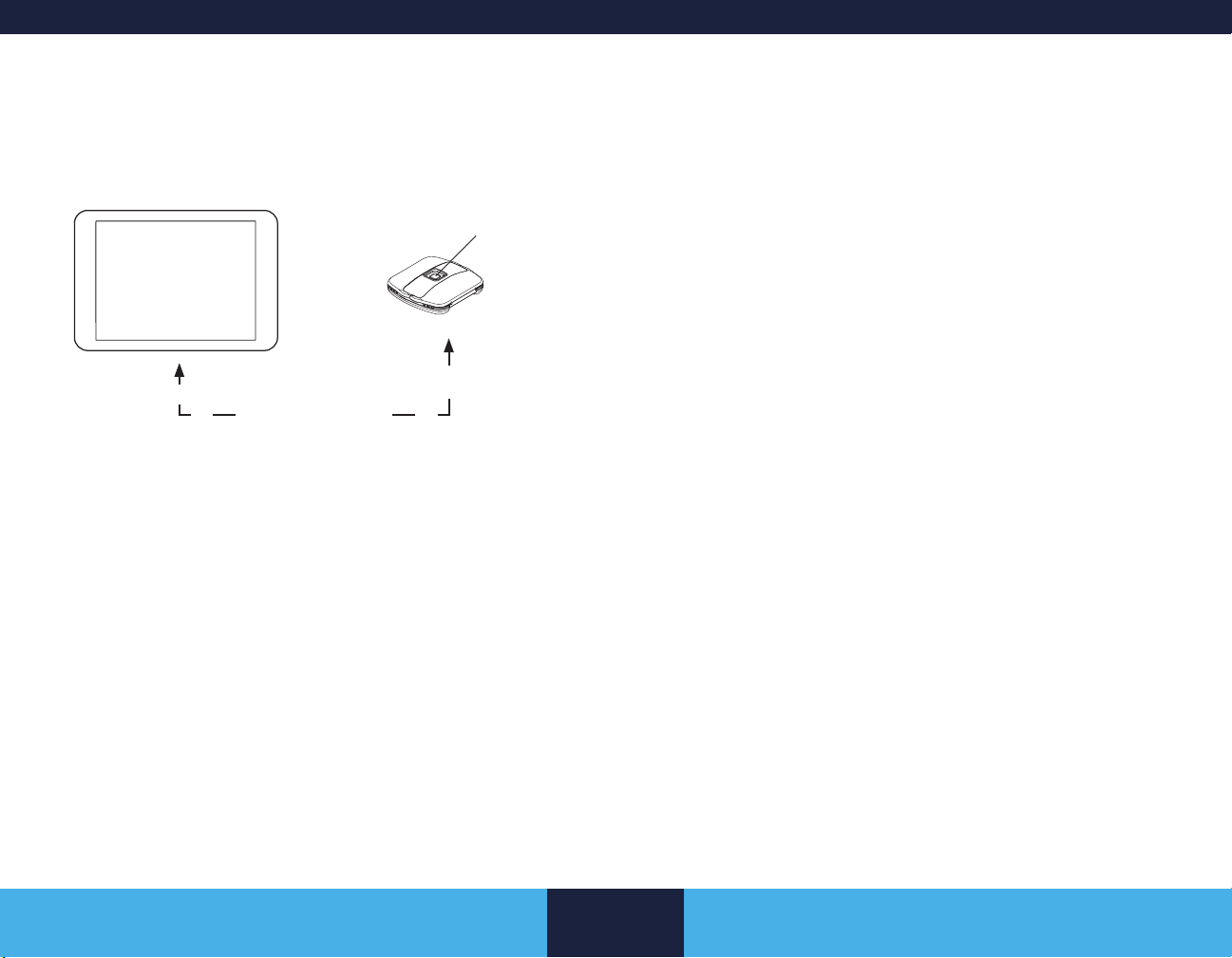
Setting up the Programming System
Clinician tablet with
clinician programmer app
The clinician tablet must remain within 3 meters
(10 feet) of the ENS.
Figure 1. Components for programming the ENS.
Preparing the clinician tablet
Refer to the Model CT900 Clinician Tablet quick start guide for
instructions on how to turn on the tablet and complete initial setup.
Check the battery level of the clinician tablet.
■ The tablet's battery level is shown on the tablet status bar
(uppermost row on the tablet screen).
■ Recharge the tablet if the battery level is low.
Finding and opening the app
1. Navigate to the apps on the clinician tablet.
Wireless external neurostimulator
(wireless ENS)
ENS button
BLUETOOTH
2. Tap the Stim Trialing app icon to open the app.
Wireless ENS preparation
■ Refer to the 97725 Wireless External Neurostimulator user
manual for the following instructions:
– Connecting the leads to the wireless ENS
– Changing the batteries in the wireless ENS
■ Check the battery level of the wireless ENS using the clinician
programmer app:
– Start a session with the wireless ENS. Refer to page
11.
– If the battery level for the ENS is too low to sustain
therapy or a programming session, a pop-up message
will notify you of the battery status and to replace the
device batteries now.
– After the ENS has been interrogated, the battery level of
the ENS is shown on the CURRENT DEVICE STATUS
screen (the screen from which you select the workow
to use for the programming session).
Note: If the wireless ENS is unresponsive or if you cannot determine
the battery level using the clinician programmer app, use another
wireless ENS.
Indicator icons in tablet status bar for ENS and BLUETOOTH wireless technology
Table 1 shows the icons that appear in the clinician tablet status bar
(uppermost row) indicating the status of ENS communication with the
clinician programmer app.
English 2021-02-15
10
Setting up the Programming System
Page 11

Table 1. ENS icons in tablet status bar.
Icon Description
The clinician programmer app is in the process of
nding ENS devices in the vicinity.
The clinician programmer app is in the process of
connecting to an ENS.
The clinician programmer app has established
communication with the ENS using BLUETOOTH
wireless technology.
Starting a session with a wireless ENS
1. Press and hold the ENS button on the wireless ENS for
approximately 1 second.
■ When the ENS button is pressed, the light on the ENS
turns on (either solid or ashing), showing that the ENS
has entered a discovery mode to begin searching for the
clinician tablet.
■ Make sure the clinician tablet is within 3 meters (10 feet)
of the ENS.
■ The light on the ENS will repeatedly ash for 90
seconds while the ENS can pair with the clinician tablet
■ If the clinician tablet detects more than one ENS, more
than one serial number may appear in the device search
results.
■ If a serial number is not provided on the back of the
ENS, do not use the device.
4. Select the serial number of the ENS you intend to congure
and tap CONNECT.
5. If conguring a new ENS, conrm the serial number of the ENS
on the pop-up message. Tap CONTINUE SESSION.
Or
If starting a follow-up session with an ENS, conrm the patient
name and serial number of the ENS on the pop-up message.
Tap CONTINUE SESSION.
The resulting screen and workow options to choose from will
depend on whether the ENS is new or already congured.
Note: If no programs were created in a previous programming
session, the workow options for a new ENS will display. Once
a program is created, the workow options for a congured
ENS will display.
6. Go to "External Neurostimulator Workows" on page 14 for
information to proceed with conguring and programming the
ENS.
2. From the initial screen of the app, tap CONNECT.
3. Watch the clinician tablet for the status of the device search
and search results.
■ If no devices are found, follow the on-screen instructions
to retry the search.
English 2021-02-15
11
Setting up the Programming System
Page 12

Overview of the Clinician Programmer App
Using Demo mode
Use Demo mode to explore the clinician programmer app without
interrogating or updating an external neurostimulator (ENS).
When the app is in Demo mode, it is not communicating with a real
external neurostimulator. Any data displayed in Demo mode is not
actual.
Demo mode can be used for training and demonstration purposes
and to familiarize yourself with the app interface before starting an
actual programming session.
1. On the initial Stimulation Trialing app screen, tap DEMO.
2. Select a device (new or congured ENS), and tap CONNECT.
3. Navigate through a workow. One workow at a time can be
explored in a Demo session.
4. To exit Demo mode, go to the Summary screen and tap EXIT
WORKFLOW.
Exiting the workow will return you to the initial app screen
where you can select DEMO again and select another device
(new or congured ENS) to explore.
Navigating through workows
The screens typically used during a programming session are
grouped into workows. The workows vary depending on the device
status (new versus congured).
After you start a workow, a workow navigator appears at the top
of the screen. For example, the Followup workow contains these
screens:
Device
Reports
Lead Select Tip Location Programs Diaries
Summary
■ To move from screen to screen, swipe left or right.
■ Alternatively, you can tap on the screen name in the workow
navigator to go directly to that screen.
– If the workow navigator extends beyond the width of
the screen, swipe the workow navigator left or right to
show the screen names that are partially hidden.
■ The current screen is underlined and highlighted.
■ If input is required in a workow screen, you will not be able to
advance to the next screen until you enter the required input.
– The app will prompt you for the required input.
– Orange asterisks indicate required elds.
Using the Side Menu
Screens not in the current workow can be accessed from the Side
Menu. For example, the Patient Info screen is in the new device
workow, but not in the Followup workow. To change patient data in
a congured device, you need to access the Patient Info screen from
the Side Menu. To access the Side Menu, tap the Side Menu button
(
) in the top-left corner on the action bar.
English 2021-02-15
12
Overview of the Clinician Programmer App
Page 13

On-screen help
Help information is available in the clinician programmer app for most
workow screens. View the help information to learn how the app
interface works and how to complete tasks on the screen.
■ To display help information, tap the Help button (
right corner on the action bar.
■ Tap the Help button (or tap anywhere on the screen) to close
the help screen.
) in the top-
Buttons and indicators on the action bar
An action bar appears at the top of all screens in all workows. Table
2 describes the buttons and indicators that may appear on the action
bar.
Table 2. Buttons and indicators.
Button / Indicator Description
Side Menu button: Tap to access
screens outside of the workow.
Back button: Tap to close a screen you
accessed from the Side Menu and return
to the previous workow screen.
Demo mode indicator: Appears in the
action bar when in Demo mode.
Stimulation toggle: Tap to turn
stimulation on or off. Green (switch to the
right) indicates that stimulation is on.
Appears in the action bar when at least
one program exists.
Button / Indicator Description
Help button: Tap to display help
information for the current screen.
Tap the Help button (or tap anywhere on
the screen) to close the help screen.
Go to Summary screen button: Tap to
go directly to the Summary screen. You
can exit the workow from the Summary
screen to properly end the programming
session.
When the app is placed in the background
When you navigate away from the Stimulation Trialing clinician
programmer app while in a programming session, the app is placed in
the background and is represented as a oating widget (Stimulation
Trialing Session in Progress) to remind you that you are still in a
session.
■ Press and drag the oating widget to move it on the tablet
screen.
■ Tap on the oating widget to return to the app and resume the
session.
English 2021-02-15
13
Overview of the Clinician Programmer App
Page 14

External Neurostimulator
Workows
When an external neurostimulator (ENS) is interrogated, the clinician
programmer app determines if the ENS is new or congured. An
ENS is identied as 'new' if it is in shelf state. An ENS is identied
as 'congured' if it has patient data stored in it. Based on the status
of the ENS, the clinician programmer app automatically presents the
applicable workow options.
■ Start Usage > Start Evaluation workow – go to page 14
Use at the start of a trial evaluation period, when the leads are
implanted and the ENS is connected.
Use for testing lead placement.
■ Followup workow – go to page 16.
Use at followup sessions with the patient during the trial period
to update therapy settings, view charts and reports.
■ End Evaluation workow – go to page 17.
Use at the last followup session with the patient at the end
of the trial period and view list of eligible implantable devices
compatible with the current therapy settings.
■ Implant Device workow – go to page 18.
Start a session with external neurostimulator and transfer data
to internal neurostimulator during an implant procedure.
Notes:
■ To display on-screen help information, tap the Help button (
■ The screens typically used during a programming session are
shown in the workow navigator. Additional screens not in the
current workow can be accessed from the Side Menu (
).
■ Unsaved information may be lost if the application is improperly
terminated during a programming session. To end a session,
go to the Summary screen and tap the EXIT WORKFLOW
button. Ending a session generates a complete session record
that is stored in a database on the clinician tablet.
Start Usage > Start Evaluation
workow
1. On the CURRENT DEVICE STATUS screen, conrm that the
device information corresponds with the intended ENS.
2. Tap START USAGE.
This action sets the In Use Date eld to the current date.
3. Under START EVALUATION, tap START.
4. Use Table 3 to guide you through the screens and tasks in the
workow.
).
English 2021-02-15
14
External Neurostimulator Workows
Page 15

Table 3. Start Evaluation workow.
Screen Tasks More information
Device Check the battery status of the external neurostimulator. Page 19
Patient Info Enter patient information. Page 19
Pain Map Tap the PAINT button, then use your nger to highlight the area on the human gure where the
patient feels pain. To remove highlight from an area on the gure, tap the ERASE button and then
tap the highlighted area.
Lead Select Select the implanted leads. Select a lead from the scrollable drop-down list, and then drag and drop
it at the appropriate electrode numbers. Tap UPDATE to save the selected lead.
Ensure leads are properly connected to the neurostimulator, and then check connectivity by tapping
the CHECK CONNECTIVITY button.
Tip Location Select the tip location for each lead. Page 20
Programs (and
subscreens)
Create programs in groups. Tap a group to make it active. A highlighted box around a group indicates
that the group is active. Tap the plus sign to add a program within a group.
Program subscreen: Assign the electrode conguration for the lead(s). Assign pulse width, rate,
and intensity.
Lead Manipulation subscreen (only applicable with more than one lead): Use to represent the
relative positioning of the implanted leads as viewed from the patient’s back.
Energy subscreen: Set parameters for SoftStart/Stop and cycling. Page 27
Patient Access subscreen: Assign the stimulation parameters that the patient can adjust. Page 28
Impedance Measure electrode impedance.
These measurements verify the integrity of lead, extension, and connector pathways. They may
provide information about lead problems (such as lead breakage, short circuit, open circuit).
Summary Conrm therapy settings.
End the session properly by tapping the EXIT WORKFLOW button.
Page 19
Page 19
Page 20
Page 21
Page 21
Page 26
Page 29
--
English 2021-02-15
15
External Neurostimulator Workows
Page 16

Followup workow
1. On the CURRENT DEVICE STATUS screen, conrm that the
patient and device information corresponds with the intended
patient and ENS.
2. Under FOLLOWUP, tap START.
3. Use Table 4 to guide you through the screens and tasks in the
workow.
Table 4. Followup workow.
Screen Tasks More information
Device Check the battery status of the external neurostimulator. Page 19
Lead Select Review the information, and make any updates. Updates may delete programmed settings. Page 19
Tip Location Review the information, and make any updates. Page 20
Programs (and
subscreens)
Diaries View the Stimulation Usage and Group Usage diaries to assess the patient’s use of the therapy. Page 33
Reports Select a report to view, download, or delete. Page 34
Summary Conrm therapy settings.
Review the groups, programs, and settings, and make any updates. Conrm that the active group is
the intended group.
Program subscreen: Assign the electrode conguration for the lead(s). Assign pulse width, rate,
and intensity.
Lead Manipulation subscreen (only applicable if more than one lead): Use to represent the
relative positioning of the implanted leads as viewed from the patient’s back.
Energy subscreen: Set parameters for SoftStart/Stop and cycling. Page 27
Patient Access subscreen: Assign the stimulation parameters that the patient can adjust. Page 28
End the session properly by tapping the EXIT WORKFLOW button.
Page 21
Page 21
Page 26
--
English 2021-02-15
16
External Neurostimulator Workows
Page 17

End Evaluation workow
1. On the CURRENT DEVICE STATUS screen, conrm that the
patient and device information corresponds with the intended
patient and ENS.
2. Tap END EVALUATION > START.
3. Use Table 5 to guide you through the screens and tasks in the
workow.
Table 5. End Evaluation workow.
Screen Tasks More information
Device Check the battery status of the external neurostimulator. Page 19
Lead Select Review the information, and make any updates. Updates may delete programmed settings. Page 19
Tip Location Review the information, and make any updates. Page 20
Programs Review the groups, programs, and settings, and make any updates. Page 21
Diaries View the Stimulation Usage and Group Usage diaries to assess the patient’s use of the therapy. Page 33
Reports Select a report to view, download, or delete. Page 34
Eligibility Review the list of devices that are compatible with the therapy parameters and programs currently
active in the ENS. Estimate battery life for Vanta or Sequentia LT neurostimulators based on the
therapy parameters and programs currently active in the ENS.
Summary End the session properly by tapping the EXIT WORKFLOW button. --
Page 32
English 2021-02-15
17
External Neurostimulator Workows
Page 18

Implant Device workow
1. On the CURRENT DEVICE STATUS screen, conrm that the
patient and device information corresponds with the intended
patient and ENS.
2. Tap IMPLANT DEVICE > START.
3. Use Table 6 to guide you through the screens and tasks in the
workow.
Table 6. Implant Device workow.
Screen Tasks More information
Device Check the battery status of the external neurostimulator. Page 19
Patient Info Enter patient information. Page 19
Pain Map Tap the PAINT button, then use your nger to highlight the area on the human gure where the
patient feels pain. To remove highlight from an area on the gure, tap the ERASE button and then
tap the highlighted area.
Lead Select Select the implanted leads. Select a lead from the scrollable drop-down list, and then drag and drop
it at the appropriate electrode numbers. Tap UPDATE to save the selected lead.
Ensure leads are properly connected to the neurostimulator, and then check connectivity by tapping
the CHECK CONNECTIVITY button.
Tip Location Indicate whether extensions are implanted. Page 20
Programs (and
subscreens)
Switch Device Press the SWITCH DEVICE button to switch from an external neurostimulator to an implanted Model
Create programs in groups. Tap a group to make it active. A highlighted box around a group indicates
that the group is active. Tap the plus sign to add a program within a group.
Program subscreen: Assign the electrode conguration for the lead(s). Assign pulse width, rate,
and intensity.
Lead Manipulation subscreen (only applicable if more than one lead): Use to represent the
relative positioning of the implanted leads as viewed from the patient’s back.
Energy subscreen: Set parameters for SoftStart/Stop and cycling. Page 27
Patient Access subscreen: Assign the stimulation parameters that the patient can adjust. Page 28
977006 Vanta or Model 977005 Sequentia LT neurostimulator.
Page 19
Page 19
Page 20
Page 21
Page 21
Page 26
Page 29
Summary Conrm therapy settings.
End the session properly by tapping the EXIT WORKFLOW button.
English 2021-02-15
18
--
External Neurostimulator Workows
Page 19

Working with Device and Patient Information
Checking battery status of the external neurostimulator
The battery level for the external neurostimulator (ENS) is shown at
the start and at the end of a programming session on the following
screens:
■ CURRENT DEVICE STATUS screen
■ Device screen
■ Summary screen
A battery image displays representing the battery level percentage:
0%, 25%, 50%, 75%, or 100%.
At the start of a programming session, if the battery level is below
25% for the ENS, a message noties you that the device is running
on low battery.
If the battery level for an ENS is too low to sustain therapy or a
programming session, a message noties you of the battery issue.
You need to replace the batteries in the ENS.
Entering patient information
Patient information such as patient name and diagnosis is entered on
the Patient Info screen. The Patient Info screen is accessed through
the workow navigator or by tapping Patient Info on the Side Menu
(
) when the screen is not part of a workow.
■ Enter the applicable patient information. Orange asterisks
indicate the required elds.
Mapping patient pain
The Pain Map screen is used to highlight areas of the body where
the patient feels pain. There are two options for updating the patient's
pain map: PAINT and ERASE. Only one can be selected at a time.
The Pain Map screen is accessed through the workow navigator or
by tapping Pain Map on the Side Menu (
part of a workow.
■ Select the PAINT option and tap the area on the human gure
to highlight where the patient feels pain.
■ Use the ERASE option to remove highlighting.
■ Tap the ROTATE button to rotate the human gure from front to
back and from back to front.
) when the screen is not
Entering lead information
The Lead Select screen is used to identify which lead models
are implanted, associate the lead electrode numbering to the
neurostimulator electrode numbering, and check connectivity of the
lead contacts or extension contacts with the neurostimulator contacts.
The Lead Select screen is accessed through the workow navigator.
■ To assign a lead, select the lead model from the scrollable
drop-down lists. Press and hold, then drag the lead image to
the appropriate electrode numbers of the device.
■ To delete a lead, tap the lead image, and then tap the X that
appears.
■ To change a lead, you must rst delete the current lead, and
then assign a new lead.
Notes:
■ Make sure that the electrode numbering on the screen
matches the electrode numbering of the implanted leads. If
English 2021-02-15
19
Working with Device and Patient Information
Page 20

necessary, you can swap congured leads using the drag-and-
drop feature.
■ On Medtronic surgical leads, the blue box on the lead arm
represents the marker band on the actual lead. For more
information about surgical leads, refer to the lead implant
manual. The marker band indicates the lead arm for electrodes
0-7.
Testing lead connectivity
Once the implanted lead(s) are assigned on the Lead Select screen,
you can check the connectivity of the lead contacts and/or extension
contacts with the neurostimulator contacts. Prior to running the
test, ensure the leads or extensions are properly connected to the
neurostimulator.
■ Tap the CHECK CONNECTIVITY button (
disabled, tap UPDATE on the Lead Select screen to save the
lead data and enable the button.)
– Green electrodes indicate that the lead contacts and/
or extension contacts have a good connection to the
neurostimulator contacts.
– Red electrodes (with an “X”) indicate a bad connection.
– If there are red electrodes, gently reconnect the leads or
extensions for a better connection to the neurostimulator
contacts. Then repeat the connectivity check.
). (If the button is
Adding uoro images
The uoro screen is accessed using the View Fluoro button at the
bottom-left of the Tip Location screen.
Note: The View Fluoro button also appears at the bottom-left of
the Lead Manipulation subscreen (accessed from the Program
subscreen).
■ Use the Add Photo button to add existing uoro images saved
in the tablet or take a photo of the uoro image displayed on
the monitor. The app can store up to four images.
■ Annotate images with the Text button. Tap where you want the
text to appear on the image and enter the text. Edit existing
text by tapping the Text button and then tapping the text you
want to edit on the screen.
■ Tap the Trash button (
uoro image exists in the uoro screen, swipe left or right to
select the image you want to delete.
) to delete an image. If more than one
Entering tip location information
The Tip Location screen is accessed through the workow navigator.
■ Select the tip location for each lead from the scrollable drop-
down lists.
English 2021-02-15
20
Working with Device and Patient Information
Page 21

Working with Groups and Programs
Programs screen
The Programs screen is used to create, copy, move, and delete
programs within groups and to dene the active group. The
Programs screen is accessed through the workow navigator.
■ Only one group can be active at a time. A highlighted box
around a group indicates the active group.
■ To make another group active, tap that group name.
■ To copy or move a program, press and hold, then drag that
program to the intended location, and then select MOVE or
COPY from the message that appears.
■ To delete a program, press and hold, then drag that program to
the Trash icon (
■ To create a new program, tap the add symbol (+) on the
desired program. This will launch the Program subscreen,
where you can assign the program settings.
■ To view the program settings for an existing program, rst
make the group active, and then tap the program to view the
Program subscreen.
Program subscreen
The Program subscreen is used to assign, review, and change
program settings for programs in the active group. The Program
subscreen is accessed by tapping a program on the Programs
screen.
■ A line is shown under the program number that is currently
displayed on the Program subscreen.
)�
■ To move from program to program within the active group,
swipe left or right on the screen. Alternatively, you can tap a
program number.
■ Use the Program subscreen to assign the electrode
conguration for the leads and to set pulse width, rate, and
intensity. Refer to "Adjusting Stimulation Parameters" on page
22.
■ From the Program subscreen, you can access the following
subscreens:
– Lead Manipulation: For more information, refer to
"Relative Lead Positioning" on page 26.
– Energy: Refer to "Customizing SoftStart/Stop and
Cycling" on page 27.
– Patient Access: For more information, refer to
"Enabling Patient Access" on page 28.
Turning stimulation on or off
The Stimulation toggle is found on the action bar at the top-right
corner of the screen. The toggle is available when at least one
program exists. When no programs exist, the area in the action bar
reads “Stimulation Not Setup.”
■ Tap the Stimulation toggle to turn stimulation on (
(
) at any time.
) or off
English 2021-02-15
21
Working with Groups and Programs
Page 22

Adjusting Stimulation Parameters
Assigning electrode conguration
Electrode conguration for the leads is assigned on the Program
subscreen.
Electrode conguration must include at least one negative (–) and
one positive (+) electrode. You cannot set intensity for the program
until you have assigned at least one negative (–) and one positive (+)
electrode to the lead.
■ Tap an electrode to change its polarity to negative (–), positive
(+), or off. Tap Update when nished.
■ To delete an electrode, press and hold, then drag that
electrode to the Trash icon (
■ To delete all assigned electrodes, tap the Select All button
(
), and then tap the Trash icon ( ).
■ To move all electrodes at once, tap the Select All button (
and then press and drag the electrodes to a new location on a
lead. This action will set the intensity to 0.0 mA.
■ To move an individual electrode, you must rst delete that
electrode and then assign a new electrode.
Note: Adding or deleting an electrode after the intensity is assigned
will reset the intensity to 0.0 mA for the affected program.
).
),
Assigning intensity, pulse width, and program rate
Intensity, pulse width, and program rate are assigned on the Program
subscreen.
During a programming session, the selected values for intensity,
pulse width, and program rate are automatically programmed into the
neurostimulator. Once intensity is set and stimulation is turned on, the
neurostimulator changes stimulation to the new setting every time a
stimulation parameter is changed.
Caution: To prevent possible uncomfortable or
unexpected stimulation (jolting or shocking sensation) during a
programming session, adjust stimulation parameters in small
increments above the perception threshold (the parameter
values at which the patient rst perceives a sensation of
stimulation).
Assigning intensity
Intensity is the strength of the pulse in milliamps (mA). The electrode
conguration for the leads must be assigned before you can set
intensity.
1. In the Program subscreen, tap INTENSITY to access the
intensity control.
2. Select the intensity using any of these controls:
■ Scrollable drop-down list.
■ Dial (press and drag the dot on the dial).
■ Back arrows (
increase.
Note: Intensity increases in increments. When intensity is
decreased, intensity decreases immediately to the new value.
) to decrease and forward arrows ( ) to
English 2021-02-15
22
Adjusting Stimulation Parameters
Page 23

3. Use these buttons, as needed:
■ Tap the Stop button (
increasing to the new value.
■ Tap the Jump button (
without incremental increases.
■ Tap the Intensity to zero button (
intensity to 0.0 mA.
) to stop stimulation from
) to jump to the new value
) to immediately set
Assigning pulse width
Pulse width is the duration of the pulses in microseconds (μs).
Caution: To prevent possible uncomfortable or
unexpected stimulation (jolting or shocking sensation),
decrease the intensity to the perception threshold (the intensity
at which the patient rst perceives a sensation of stimulation)
before changing the pulse width. After changing the pulse
width, slowly increase the intensity.
1. In the Program subscreen, tap PULSE WIDTH to access the
pulse width control.
2. Select the pulse width using any of these controls:
■ Scrollable drop-down list.
■ Dial (press and drag the dot on the dial).
■ Back arrows (
increase.
3. If stimulation is on, the Stop and Jump buttons become
available when the pulse width is increased. Use these
buttons, as needed.
■ Tap the Stop button (
increasing to the new value.
) to decrease and forward arrows ( ) to
) to stop stimulation from
■ Tap the Jump button (
without incremental increases.
) to jump to the new value
Assigning program rate and device rate
Rate is the frequency of pulses per second, in hertz (Hz). The device
rate is the initial rate for each program in that group. A program rate is
a fractioned value of the device rate.
To set a device rate
1. In the Program subscreen, tap PROGRAM RATE to access
the rate control.
2. Select the device rate using any of these controls:
■ Scrollable drop-down list.
■ Dial (press and drag the dot on the dial).
■ Back arrows (
increase.
To set a program rate
A program rate is a fractioned value of the device rate.
The rate ratios available: 1/1, 1/2, 1/3, 1/4, and so on, up to 1/20.
1. If you need to set a program rate, tap the pop-up scrollable list
next to PROGRAM RATE in the rate control.
2. Select a program rate. That rate will be applied to all the
programs with the same number in the other groups as well.
Program rate example:
■ The device rate is set at 100 Hz.
■ 1/2: 50 Hz is selected as the program rate for that
program in the group.
) to decrease and forward arrows ( ) to
English 2021-02-15
23
Adjusting Stimulation Parameters
Page 24

■ This program will now deliver pulses at 50 pulses per
second. Meanwhile, the other programs set with the
device rate will still deliver 100 pulses per second.
3. Tap CLOSE to close the control.
4. Reassess limits assigned in the Patient Access subscreen
after modifying stimulation parameters. Refer to "Limits" on
page 28.
Using electrode redistribution (assigning
percentage of intensity for individual electrodes)
In most programming sessions, the value selected for the intensity is
distributed evenly among the assigned electrodes. Use the electrode
redistribution feature when you want to assign a lower or a higher
percentage of the intensity to an individual electrode in the program.
On the Program subscreen, the distribution of the intensity among
the electrodes is shown as percentages for the positive (+) electrodes
and as a value for the negative (–) electrodes.
Note: The Device Electrode Redistribution feature must be
activated before you can use the feature. The feature only needs to
be activated once. It remains active across programming sessions.
1. To activate the Device Electrode Redistribution feature:
a. Tap the Display All (
subscreen. The Display All subscreen can only be
accessed from an active program with at least one
electrode pair.
b. In the Display All subscreen, check the status of the
DEVICE ELECTRODE REDISTRIBUTION toggle.
If the toggle is green and the switch is to the right
(
), the feature is activated. If the toggle is blue
and the switch is to the left, tap the toggle to activate the
feature.
) button in the Program
c. Tap the CLOSE button to return to the Program
subscreen.
2. In the Program subscreen, tap the electrode you intend to
adjust.
Notes:
■ To maintain the overall balance of energy between
the polarities, the electrodes that will be impacted by
the redistribution will have the same polarity as the
electrode that you selected to adjust.
■ Electrode redistribution will automatically rebalance
the delivered stimulation amplitudes. After making
adjustments, review the electrode contribution
percentages.
3. Select the percentage of the intensity that you want to assign
to the electrode.
Notes:
■ Electrode intensity increases in increments.
■ If the neurostimulator is unable to deliver the intensity
value in combination with the values set for the pulse
width and rate, an alert will notify you that stimulation
output is below the programmed intensity. Refer to "Out
of regulation (OOR) message" in the Troubleshooting
section on page 38.
4. Repeat if you want to adjust another electrode.
5. Tap CLOSE to close the control.
English 2021-02-15
24
Adjusting Stimulation Parameters
Page 25

Equalizing intensity across electrodes
Use the Equalize feature to evenly distribute intensity across the
assigned electrodes. You can equalize intensity for a single program
or for all programs with unequal distribution.
To equalize a single program
1. In the Program subscreen, tap the Equalize (
2. Tap YES in the conrmation pop-up to proceed.
) button.
■ Electrode number 1 is assigned a positive (+) polarity.
You can either start the scanning process from the 0 and 1 electrodes,
or you can move the negative and positive electrode pair to another
position on the lead and start the scanning process from there.
To use IntelliStim, you must rst activate the Device Electrode
Redistribution feature. The feature only needs to be activated once.
It remains active across programming sessions.
1. To activate the Device Electrode Redistribution feature:
3. Use the INTENSITY control to select an intensity.
To equalize all programs with unequal distribution
1. In the Program subscreen, tap the Display All (
The Display All subscreen can only be accessed from an
active program with at least one electrode pair.
2. In the Display All subscreen, tap the DEVICE ELECTRODE
REDISTRIBUTION toggle.
3. Tap DISABLE in the conrmation pop-up.
This action equalizes intensity across all programs with
unequal distribution and reduces the intensity to zero for those
programs. It also disables the electrode redistribution and
IntelliStim features.
4. Tap the CLOSE button to return to the Program subscreen.
) button.
Using IntelliStim
IntelliStim is a scanning process in which common combinations of
electrodes are scanned across the lead using the selected intensity.
IntelliStim can help nd which electrodes to select to deliver therapy.
When IntelliStim begins, the lead is automatically populated with a
negative (–) and positive (+) electrode pair:
■ Electrode number 0 is assigned a negative (–) polarity.
a. In the Program subscreen, tap the Display All button.
The Display All subscreen can only be accessed from
an active program with at least one electrode pair.
b. In the Display All subscreen, check the status of the
DEVICE ELECTRODE REDISTRIBUTION toggle.
If the toggle is green and the switch is to the right
(
), the feature is activated. If the toggle is blue
and the switch is to the left, tap the toggle to activate the
feature.
c. Tap the CLOSE button to return to the Program
subscreen.
2. In the Program subscreen, tap the INTELLISTIM button (
and follow the on-screen instructions.
3. Position the electrode pair on the lead where you want to start
the scanning process.
■ Tap the Forward button (
pair down the lead.
■ Tap the Back button (
up the lead.
■ Tap the Jump Forward button (
electrode pair to the top of the lead or electrode column
(if a surgical lead) on the right.
) to advance the electrode
) to advance the electrode pair
) to move the
)
English 2021-02-15
25
Adjusting Stimulation Parameters
Page 26

■ Tap the Jump Back button ( ) to move the electrode
pair to the top of the lead or electrode column (if a
surgical lead) on the left.
■ Or move the electrode pair directly to another location
on the lead by tapping a target electrode on the lead.
(This option becomes unavailable once the Play button
is pressed for the rst time.)
4. Use the Intensity control to set the intensity.
■ If the neurostimulator is unable to deliver the intensity
value in combination with the values set for the pulse
width and rate, an alert will notify you that stimulation
output is below the programmed intensity. Refer to "Out
of regulation (OOR) message" in the Troubleshooting
section on page 38.
5. Tap the Play and Pause buttons to start and pause the
scanning process.
■ The button marked X2 shows the default speed. Tap
the button once to reduce speed (the button will now be
marked X1). Tap the button again to change the speed
back to X2.
6. Ask the patient to provide their feedback during the scanning
process to assess which electrodes to select to deliver therapy.
Relative Lead Positioning
Use the Lead Manipulation subscreen (accessed from the Program
subscreen) to represent the relative positioning of the implanted leads
as viewed from the patient’s back. The subscreen is only applicable if
more than one lead is congured.
■ To swap the relative position of the leads (for example, to
switch the position of lead #2 with lead #1), press and hold,
then drag a lead to the location of the other lead.
Repositioning the leads relative to each other on the Lead
Manipulation subscreen updates how the leads are shown on the
Programs screen and Program subscreen.
The uoro screen can be accessed using the View Fluoro button at
the bottom-left of the Lead Manipulation subscreen (it also appears
at the bottom-left of the Tip Location screen). Refer to "Adding uoro
images" on page 20 for more information.
7. Tap DONE if you nd an effective electrode combination.
8. If desired, use IntelliStim to create another program in the
same group for the other lead or other electrode column (if
programming a surgical lead).
English 2021-02-15
26
Relative Lead Positioning
Page 27

Customizing SoftStart/Stop and Cycling
Use the Energy subscreen (accessed from the Program subscreen)
to customize the optional device settings for the SoftStart/Stop and
Cycling features. These features are designed to increase patient
comfort and ease of use.
Changing SoftStart/Stop settings
SoftStart/Stop slowly increases the intensity when stimulation is
turned on and slowly decreases the intensity when stimulation is
turned off. The slow ramping may feel more comfortable to sensitive
patients.
SoftStart/Stop is assigned at the device level: that is, it is either on
or off for all groups. The SoftStart/Stop feature defaults to “on” with a
duration of 4 seconds.
■ In the Energy subscreen, use the SOFTSTART/STOP drop-
down list to select a duration or to turn SoftStart/Stop off.
Turning cycling on or off
Cycling turns stimulation on and off at clinician-determined intervals.
Due to a carryover effect, the patient may continue to experience
symptom suppression during the cycling off time. The default setting
for the cycling feature is “off.”
1. In the Energy subscreen, tap the CYCLING toggle to turn
cycling on (
) or off ( ).
■ When cycling is turned on, all existing programs are
enabled for cycling as the default per program number.
Green (
enabled.
■ To disable cycling for a program, tap the toggle next
to that program number. This will affect that program
number in all the groups.
) indicates that the program number is
2. If cycling is on, select the durations for the ON TIME and OFF
TIME intervals.
3. Under the PROGRAM heading:
English 2021-02-15
27
Customizing SoftStart/Stop and Cycling
Page 28

Enabling Patient Access
Use the Patient Access subscreen (accessed from the Program
subscreen) to assign patient controls, if appropriate for the patient.
There are three patient controls on the Patient Access subscreen:
Cycling, Adjustment, and Limits.
Cycling
The Cycling patient control on the Patient Access subscreen
provides the ability to enable or disable patient control of cycling. It
can only be enabled when cycling has been turned on in the Energy
subscreen. The default setting for the cycling feature is “off."
Adjustment
Enabling the Adjustment patient control on the Patient Access
subscreen allows the patient to increase or decrease intensity for all
programs in the active group at the same time.
■ Under the ADJUSTMENT heading, tap the ALL PROGRAMS
TOGETHER toggle to enable (
patient control.
Limits
The Limits patient control on the Patient Access subscreen
provides the ability to enable or disable patient control of stimulation
parameters (intensity, pulse width, device rate). When patient control
is enabled for a stimulation parameter, the patient can adjust that
stimulation parameter using the patient programmer.
If patient control is enabled, the upper patient limit for the stimulation
parameter must be assigned. The lower patient limit is set to the
lowest possible value by default and is not customizable. Patient
control of stimulation parameters is assigned at the group level.
) or disable ( ) the
Note: By default, patient control of intensity is enabled, and patient
control of pulse width and group rate is disabled.
1. Under the LIMITS heading, tap the toggle next to the
stimulation parameter name to enable (
patient control of the stimulation parameter.
2. For enabled stimulation parameters, set the upper patient limit
using any of these controls:
■ Scrollable drop-down list.
■ Dial (press and drag the dot on the dial).
3. After the patient controls are dened, tap UPDATE.
Intensity
■ The lowest allowable option for the upper patient limit is
determined by the highest intensity setting in the group's
existing programs.
Pulse width
■ The lowest allowable option for the upper patient limit is
determined by the highest pulse width setting in the group's
existing programs.
Device rate
■ The lowest allowable option for the upper patient limit is
determined by the current rate setting for the device.
Effect of subsequent parameter changes
■ During a subsequent programming session, if a parameter is
increased above the upper patient limit, the upper patient limit
automatically changes to that new value.
) or disable ( )
English 2021-02-15
28
Enabling Patient Access
Page 29

Switch Device
The Switch Device feature is used to transfer some data, including
patient and lead information, pain map, and uoro images, from the
external neurostimulator to a new implanted neurostimulator. The
Switch Device screen is accessed in the Implant Device workow
through the workow navigator
Note: The Switch Device feature is only available with the Model
977006 Vanta and Model 977005 Sequentia LT implantable
neurostimulators.
1. Choose between the Vanta (977006) and the Sequentia LT
(977005) neurostimulators in the dropdown menu.
2. Tap the SWITCH DEVICE button.
3. Tap the SWITCH DEVICE button in the pop-up box to conrm
that you want to transfer congured information from the ENS
to the implantable neurostimulator.
4. The relevant clinician programmer application will launch
automatically.
Checking System Performance
The measurement functions on the Impedance screen assist in
identifying problems with components of the implanted system.
Measurements and diagnostic data obtained from the clinician
programmer app are intended to aid in your clinical assessment.
However, as with any electronic system, internal and external factors
can inuence neurostimulator measurements. For example, changes
in lead position can affect the stimulation current or the impedance
measurement. If you obtain a reading that seems inconsistent with
your observations, repeat the measurement.
Note: Measure impedance at the beginning of each programming
session. These measurements verify the integrity of lead, extension,
and connector pathways. They may provide information about lead
problems (such as lead breakage, short circuit, open circuit). For
example, measurements that show a signicant increase in electrode
impedance can indicate a fractured lead conductor or a loose
setscrew. Conversely, a signicant decrease in electrode impedance
can indicate shorted conductors or a break in lead insulation.
Measurements taken at the beginning of the session may be useful in
interpreting diagnostic data collected since the previous session.
Testing impedance
The Impedance screen is accessed through the workow navigator.
Note: The Impedance screen can be accessed in the Side Menu
(
) when it is not part of a workow.
1. On the Impedance screen, tap the MEASURE ALL
IMPEDANCES button (
).
English 2021-02-15
2. Tap the START button on the pop-up screen.
3. After the test is complete, review the impedance results.
29
Switch Device
Page 30

Notes:
■ If all impedance values are within range, the message "All
impedances are within normal range" appears in the GOOD
box.
■ If any impedance value is out of normal ranges (too low or too
high), the results appear in either the AVOID box or the DO
NOT USE box. Refer to "Troubleshooting Electrode Impedance
Results" on page 30.
■ The impedance value shown for each electrode is measured
with respect to the selected reference electrode. Use the
REFERENCE ELECTRODE scrollable drop-down list to select
a different reference electrode, if applicable.
■ Once an impedance test is performed, results can be viewed
at any time during the programming session by returning to
the Impedance screen. You can also view or print the Session
Report, which shows the impedance measurements.
Troubleshooting Electrode Impedance Results
The AVOID and DO NOT USE boxes on the Impedance screen
identify where low impedance or high impedance was measured in
the system. Refer to Table 7 for more information about impedance
results indicators.
Table 7. Impedance results indicators.
Icon Description
GOOD (green electrodes with a check mark): Indicates
that the impedance measurement value for the electrode
is within the normal range (300 - 4,000 ohms).
AVOID (orange electrodes with an exclamation point):
Possible open circuit:
• Using these electrodes may increase energy
consumption or impact therapy efcacy.
• Indicates that a high impedance (4,000 - 40,000 ohms)
has been detected between electrodes. The Avoid icon
is displayed and adjacent to the number of the electrodes
where high impedance has been detected.
Possible short circuit:
• Indicates that a low impedance (under 300 ohms) has
been detected between electrodes.
• The electrode combinations where possible shorts are
detected are listed under the text. The electrodes in these
combinations will also be listed in the Avoid list.
DO NOT USE (red electrodes with an "X"): Indicates that
there is a strong likelihood of opens (over 40,000 ohms)
in the system.
Refer to the troubleshooting details for high impedance and low
impedance on the following pages. For further assistance with
English 2021-02-15
30
Troubleshooting Electrode Impedance Results
Page 31

troubleshooting electrode impedance results, contact Medtronic using
the contact information listed on the back cover of this manual.
High impedance troubleshooting
Caution: When troubleshooting issues related to
impedance measurements, follow these instructions correctly
and completely to identify and resolve the issue.
■ Mistaking an undamaged component as damaged could
result in unnecessary surgical revision.
■ Failure to identify a damaged component could result in
unresolved intermittent or loss of stimulation.
High impedance suggests a possible open circuit in the system. High
impedance could be caused by a broken wire, loose connection, or
highly resistive tissue.
High impedance: >4,000 ohms
1. Analyze electrode impedance measurement results. An outlier
measurement may indicate an issue with a wire. Ensure
that all leads and extensions are fully inserted and measure
impedance again.
For more information about measuring electrode impedance,
refer to "Testing impedance" on page 29.
2. If a trend towards normal impedance range is not observed,
disconnect the lead from the extension (if applicable) and
reconnect the external neurostimulator to test the impedance
of the lead alone.
■ If the impedance value is between 300 and 4,000 ohms,
then the lead is intact.
■ If the impedance value is greater than 4,000 ohms,
visually or uoroscopically inspect the lead for damage.
3. If lead is intact, reconnect the lead to the extension (if
applicable) and use the external neurostimulator to test the
impedance of the lead and extension together.
■ If the extension impedance value is between 300 and
4,000 ohms, the extension is intact. If the extension
impedance value exceeds 4,000 ohms, visually or
uoroscopically inspect the extension and extension
connection for damage.
■ If two extensions are being used (one on each of two
leads), switch the extensions with one another and
measure impedance again to see if the out-of-range
impedance value is specic to one of the extensions. If
the out-of-range impedance value is specic to one of
the extensions, consider replacing that extension.
4. If the previous steps fail to reveal the underlying issue, assess
whether it is possible to achieve therapy without using the
electrodes with high impedance.
5. If troubleshooting measures fail to resolve the high impedance
values, consider substituting new components in the
neurostimulation system as needed.
Low impedance troubleshooting
Low impedance suggests a possible short circuit in the system that
can lead to inadequate therapy.
Low impedance: <300 ohms
Avoid using electrodes with a low impedance. Assess whether it
is possible to achieve therapy without using the electrodes with
low impedance. If the low-impedance electrodes are necessary for
programming, revision surgery may be needed.
English 2021-02-15
31
Troubleshooting Electrode Impedance Results
Page 32

Eligibility
The Eligibility screen is accessed through the workow navigator
in the End Evaluation workow or by tapping Eligibility in the Side
Menu (
The following information explains what the Eligibility screen does
and what it requires:
Estimating battery longevity
Battery longevity for the implantable neurostimulator depends on
the therapy conguration and usage. The ESTIMATE BATTERY
LONGEVITY FOR VANTA OR SEQUENTIA LT feature is a calculator
that allows you to estimate battery longevity based on the current
program and group settings, along with the number of hours per day
the patient might use each group.
1. In the Eligibility screen tap the ESTIMATE BATTERY
) when it is not part of a workow.
■ Lists the implantable neurostimulators that allow the same
parameters as the programs that are currently active in the
external neurostimulator (ENS) used for the trial evaluation.
■ Automatically updates each time you change parameters for
any active program and when you change the active group in
the ENS.
■ Requires at least one active program in the ENS in order to list
the implantable neurostimulators that are eligible to consider
for implant.
■ If the Model 977006 Vanta and/or Model 977005 Sequentia LT
implantable neurostimulators are eligible, use the ESTIMATE
BATTERY LONGEVITY FOR VANTA OR SEQUENTIA LT
feature to estimate battery life based on current programs.
LONGEVITY FOR VANTA OR SEQUENTIA LT button.
2. For each group, press and drag the dot on the slider to set
hours per day of group usage.
■ Use the GROUP drop-down lists to view the programs
within each group.
■ Group usage can be set to a total of 24 hours among all
groups.
3. Tap ESTIMATE.
4. Review the estimates. Estimates are shown for three different
impedance ranges.
5. Tap CLOSE to return to the Eligibility screen.
Notes:
■ Battery longevity should be re-estimated if changes are made
to programming.
■ For all other implantable neurostimulator models, refer to the
System Eligibility and Battery Longevity reference manual for
more information about neurostimulator eligibility.
Removing patient-identifying information before ENS disposal
The Model 97725 external neurostimulator (ENS) is a single-use
device. Remove patient-identifying information from the ENS before
disposal.
1. Start a session with the ENS and select the IMPLANT DEVICE
workow.
2. Swipe to the Patient Info screen.
3. Replace the patient's name with an x in the FIRST NAME and
LAST NAME elds.
English 2021-02-15
4. Tap UPDATE.
32
Eligibility
Page 33

5. Go to the Summary screen and tap EXIT WORKFLOW.
Viewing Diaries
The charts accessed from the Diaries screen provide overviews of
how the patient is using the external neurostimulator.
Stimulation Usage
The Stimulation Usage chart shows the patient's stimulation usage.
The chart displays the percentage of time per day that stimulation is
on over a 30-day period. The metrics provide the average percentage
of stimulation usage over the last 30 days and the percentage of time
stimulation was on since the last programming session.
Note: If 30 days of stimulation usage data is not available, the
calculations are based on the available number of days.
Group Usage
The Group Usage chart displays the percentage of time that each
group was used for the last 30 days or since the last programming
session if less than 30 days.
English 2021-02-15
33
Viewing Diaries
Page 34

Working with Reports
The following report types are available from the Reports screen:
■ Session Report: Contains information about the settings
programmed into the neurostimulator during a programming
session as well as therapy usage and system status
information.
■ Medtronic Data Report: Contains information about the
Medtronic data collected from the neurostimulator. This
report is used by Medtronic personnel when troubleshooting.
To compile a Medtronic Data Report, refer to "Compiling a
Medtronic Data Report" on page 37.
The Reports screen is accessed through the workow navigator or by
tapping Reports on the Side Menu (
You can also tap REPORTS on the initial app screen to view reports
for a patient without having to start a session.
Note: Any report generated in Demo mode is labeled DEMO MODE
at the top of the report.
Using the Reports screen
1. Select a report type from the drop-down list. The default is
Session Report.
) when not part of a workow.
Table 8. Report buttons.
Button Description
View button – to view the report in PDF format.
This action takes you out of the clinician programmer
app. The app runs in the background and your
session data remains intact.
Share button – to send the PDF report to another
destination.
This action takes you out of the clinician programmer
app. The app runs in the background and your
session data remains intact.
Download button – to download and save the PDF
report on the clinician tablet.
This action saves a PDF le in the default reports
folder on the clinician tablet.
Delete button – to delete the selected patient
session record from the clinician tablet.
When a session record is deleted, the data no longer
exists on the clinician tablet. However, deleting a
session record does not delete any existing PDF les
created from that record and stored on the clinician
tablet.
2. (Optional) Use the lter options to nd the patient data you
want.
3. Tap the desired patient session record in the scrollable list. The
most recent patient session record appears at the top.
4. Tap one of the buttons shown in Table 8.
English 2021-02-15
34
Working with Reports
Page 35

Patient Data Service app
The Patient Data Service app manages the storage of patient session
data in a locally stored database on the clinician tablet.
The Patient Data Service app can be used to access or delete patient
session data for any patients whose Medtronic devices have been
programmed using any clinician programmer app on the clinician
tablet.
The Patient Data Service app can also be used to adjust (or disable)
the PDF auto-delete feature, which automatically deletes PDF les
from the default reports folder on the clinician tablet after a designated
amount of time.
Finding and opening the app
1. Navigate to the Apps on the clinician tablet.
2. Find the icon for the Patient Data Service app.
3. Tap the icon to open the app.
Table 9. Patient Data Service buttons.
Button Description
Import button – to import the selected session
record into the Reports screen in the clinician
programmer app.
Refer to "Using the Reports screen" on page 34.
Delete button – to delete the selected patient
session record from the clinician tablet.
When a session record is deleted, the data no longer
exists on the clinician tablet. However, deleting a
session record does not delete any existing PDF les
created from that record and stored on the clinician
tablet.
Deleting multiple patient session records at once
1. In the Patient Data Service app, use the lter options to nd
the patient data you want.
Accessing or deleting a patient session record
1. In the Patient Data Service app, use the lter options to nd
the patient data you want.
2. Tap the desired patient session record in the scrollable list. The
most recent patient session record appears at the top.
3. Tap one of the buttons shown in Table 9.
English 2021-02-15
2. Tap and hold on any record in the results list to activate the
multiple record selection feature.
3. Tap the applicable checkboxes to select all records you want to
delete from the scrollable list.
4. Tap the Trash icon (
records to be deleted is shown next to the icon.
Note: To cancel without deleting records, tap the back arrow in
the upper left corner.
35
Patient Data Service app
) to delete the records. The number of
Page 36

Setting the PDF auto-delete feature
Use the auto-delete feature to automatically delete PDF les stored
on the clinician tablet based on a timeframe you select. The autodelete feature is enabled by default with a preset amount of time.
This feature only deletes PDF les from the default reports folder on
the clinician tablet. It does not affect patient session data stored in the
database.
1. In the Patient Data Service app, tap the Settings button (
2. Select PDF Auto Delete.
3. Select the appropriate auto-delete settings, and then tap
UPDATE.
).
Viewing System Information
The About System screen is accessed from the Side Menu ( ).
This screen provides the following information:
■ System information (such as model numbers, serial numbers,
rmware numbers, version numbers) for the external
neurostimulator (ENS), clinician tablet, clinician programmer
app, and controller (patient programmer).
Includes the information for the controller (patient programmer)
that most recently communicated with the neurostimulator or
was paired with the clinician tablet.
■ Trademarks and licenses information.
This screen provides the following capabilities:
■ Ability to change the device date and time for the ENS.
■ Ability to generate a Medtronic Data Report.
Viewing information about system components
On the About System screen, tap the tab for the component
information you want to view.
English 2021-02-15
Viewing information about trademarks and licenses
On the About System screen, tap the Licenses tab, and then tap the
button for the information you want to view.
36
Viewing System Information
Page 37

Changing device date/time or implant date information
The Device tab on the About System screen shows the device date
and device time. You can change the date and time information if
needed.
■ Tap the date that you want to change. Use the calendar
selector to select a new date, and then tap outside the
calendar.
■ Tap the time that you want to change. Use the time selector to
select a new time, and then tap outside the time.
Compiling a Medtronic Data Report
The Medtronic Data Report tab on the About System screen is
used to compile a report containing information about the Medtronic
data collected from the neurostimulator.
■ Tap the COMPILE REPORT button (
Medtronic Data Report. You cannot cancel the action after it is
initiated.
To access previously compiled Medtronic Data Reports, refer to
"Working with Reports" on page 34.
) to compile the
Viewing Alerts
The clinician programmer app displays alerts to inform you of specic
events or changes in the system. There are three levels of alerts in
the clinician programmer app: warning, caution, and information.
When alerts are present, an ALERTS button displays on the screen.
The button shows the number of alerts that need to be acknowledged.
Read and follow the instructions given in the alert.
Working with alerts
■ To view alerts, tap the ALERTS button in the lower left corner
of the screen. Each alert appears in a separate pop-up box.
– Swipe left or right to view individual alerts.
■ To close an alert without dismissing it, tap the X (or anywhere
outside of the alert pop-up box).
■ To dismiss an alert, tap the DISMISS button. The alert will be
marked as a dismissed alert.
■ When all alerts are dismissed, the ALERTS button reads "NO
ALERTS". Those alerts, however, now exist as dismissed
alerts and can still be viewed.
■ To view dismissed alerts, tap the NO ALERTS button, and then
tap the SHOW DISMISSED button.
■ To restore a dismissed alert, tap the RESTORE button.
English 2021-02-15
37
Viewing Alerts
Page 38

Troubleshooting
Approach troubleshooting conservatively. Prior to performing
invasive procedures, ensure that all noninvasive solutions have been
considered. If additional assistance is needed, contact Medtronic
using the contact information listed on the back cover of this manual.
The clinician programmer app displays messages to inform you of
issues in the system. Follow the instructions given in the message.
Data validation error message
During initial interrogation, the app performs a data validation check
to ensure that the data in the neurostimulator is valid and can be
understood. If data is found to be invalid, the app displays a data
validation error message and provides the option to clear the invalid
data.
Power on reset (POR) message
If a power on reset (POR) message displays at initial interrogation,
this indicates that one or more POR events occurred since the last
programming session. If a power on reset message displays while in
a current programming session, the session will end and any unsaved
data will be lost.
Using impedance measurements for troubleshooting
Refer to "Checking System Performance" on page 29.
Out of regulation (OOR) message
An out of regulation (OOR) message indicates that the delivered
intensity may be lower than the programmed intensity for the
indicated programs because of low impedance. If an out of regulation
situation occurs, decrease settings or reduce the number of
electrodes for the indicated programs.
English 2021-02-15
38
Troubleshooting
Page 39

English 2021-02-15
39
Page 40

Manufacturer
Medtronic, Inc.
710 Medtronic Parkway
Minneapolis, MN 55432
USA
www.medtronic.com
Tel. +1-763-505-5000
REP
EC
Authorized Representative
in the European Community
Medtronic B.V.
Earl Bakkenstraat 10
6422 PJ Heerlen
The Netherlands
Tel. +31-45-566-8000
Europe/Africa/Middle East Headquarters
Medtronic International Trading Sàrl
Route du Molliau 31
Case Postale 84
CH - 1131 Tolochenaz
Switzerland
www.medtronic.eu
Tel. +41-21-802-7000
Asia-Pacic
Medtronic International Ltd.
50 Pasir Panjang Road
#04-51 Mapletree Business City
Singapore 117384
Singapore
Tel. +65-6870-5510
*M006346C001*
© Medtronic, Inc. 2020
All Rights Reserved
M006346C001 Rev A
2021-02-15
 Loading...