

Page 1

Restore
TM
Clinician Programmer
Application
Programming Guide
Neurostimulation systems for pain therapy
Neurostimulator models 37022, 37701, 37702, 37703, 37704,
37711, 37712, 37713, 37714, 97702, 97712, 97713, 97714
Application version 1.0
A71100
Page 2

Explanation of symbols
Medtronic, Medtronic logo and Further, Together are trademarks
of Medtronic. AdaptiveStim™, GroupAdjust™, Itrel™, N'Vision™,
Conformité Européenne (European
Conformity)
Authorized representative in the European
Community
PrimeAdvanced™, Restore™, RestoreAdvanced™, RestorePrime™,
RestoreSensor™, RestoreUltra™, SoftStart/Stop™, SureScan™, and
TargetMyStim™ are trademarks of a Medtronic company.
Android™ is a trademark of Google LLC.
The BLUETOOTH
®
word mark and logos are registered trademarks
owned by Bluetooth SIG, Inc., and any use of such marks by
Manufacturer
Medtronic is under license.
®
Wi-Fi
and Wi-Fi Alliance® are registered trademarks of Wi-Fi Alliance.
For USA audiences only
Importer
Refer to the indications sheet for indications and related information.
Refer to the device implant manual for device description, package contents, device specications, and instructions for use.
Refer to the appropriate information for prescribers booklet for contraindications, warnings, cautions, adverse events summary, individualization of treatment,
patient selection, use in specic populations, resterilization, and component disposal.
Refer to the MRI Guidelines for Medtronic Neurostimulation Systems for Chronic Pain instructions for use manual for the MRI conditions and MRI-specic
warnings and cautions for conducting an MRI scan.
Refer to the System Eligibility, Battery Longevity, Specications reference manual for neurostimulator selection, battery longevity calculations, and specic
neurostimulator specications.
Refer to the Model 8880T2 Communicator technical manual for warnings, cautions, device description, package contents, device specications, instructions
for use, maintenance information, and the electromagnetic compatibility (EMC) declaration.
Refer to the literature provided by the clinician tablet manufacturer for information regarding wireless use.
Refer to the clinical summary booklet for information on the clinical study results of the neurostimulation system and individualization of treatment.
English 2021-04-15
2
Page 3

Table of Contents
Description of the Programming System ������������ 7
Model A71100 Restore Clinician Programmer Application .. 7
Other components of the programming system .................. 7
Programmable Settings ���������������������������������������� 8
Stimulation parameters ........................................................ 8
Groups and programs .......................................................... 8
Optional features ................................................................. 8
Data Security and Network Connectivity ���������� 10
Data security ...................................................................... 10
Network connectivity .......................................................... 10
Installing application updates ........................................... 10
Installing communicator updates ....................................... 10
Returning the clinician tablet ............................................. 10
General Warnings and Cautions �������������������������11
MRI warning for scan eligibility .......................................... 11
MRI warning for trial stimulation ........................................ 11
Sterile eld warning for programming components ........... 11
EMI caution for telemetry signal disruption ........................ 11
Cautions related to clinician programming and
possible interactions with other devices ............................ 11
Setting up the Programming System ���������������� 12
Preparing the clinician tablet ............................................. 12
Finding and opening the app ............................................. 12
Pairing the communicator to the clinician tablet ................ 12
Positioning the communicator over the neurostimulator .... 13
Initiating communication with the neurostimulator ............. 13
Overview of the Clinician Programmer App ���� 15
Using Demo mode ............................................................. 15
Navigating through workows ............................................ 15
Using the Side Menu ......................................................... 15
On-screen help .................................................................. 16
Buttons and indicators on the action bar ........................... 16
When the app is placed in the background ....................... 17
Overview of the Communicator ������������������������� 18
Using the USB connector cable ......................................... 18
Checking battery status of the communicator ................... 18
Communicator icons on the tablet status bar .................... 19
External Neurostimulator Workows ���������������� 20
New ENS: Start Usage > Start Evaluation workow .......... 20
Congured ENS: Followup workow ................................. 22
Congured ENS: End Evaluation workow ....................... 23
English 2021-04-15
3
Page 4

Implantable Neurostimulator Workows ����������� 24
New INS: Start Usage > Implant Device workow .............24
Congured INS: Followup workow ................................... 26
Congured INS: View MRI workow .................................. 27
Working with Device and Patient Information �� 28
Positioning Leads Relative to Implant
Location ���������������������������������������������������������������� 34
Customizing SoftStart/Stop and Cycling ���������� 35
Changing SoftStart/Stop settings ......................................35
Turning cycling on or off ....................................................35
Checking battery status of the neurostimulator .................28
Entering implant location ...................................................28
Entering patient information ............................................... 28
Entering lead information ................................................... 28
Testing lead connectivity .................................................... 29
Entering extension, abandoned lead, or tip location
information ......................................................................... 29
Clearing information in external neurostimulator for
re-use ................................................................................29
Working with Groups and Programs ����������������� 30
Programs screen ...............................................................30
Program subscreen ...........................................................30
Turning stimulation on or off ..............................................30
Adjusting Stimulation Parameters ��������������������� 31
High-output interlocks ........................................................ 31
Shared electrodes ............................................................31
Assigning electrode conguration ...................................... 31
Assigning pulse width, rate, and amplitude .......................32
Enabling Patient Access ������������������������������������� 36
Limits .................................................................................36
TargetMyStim ..................................................................... 37
Adjustment ......................................................................... 37
Programming Scheduled Therapy ��������������������� 38
Checking System Performance�������������������������� 39
Testing electrode impedance ............................................. 39
Troubleshooting electrode impedance results ...................40
Testing group impedance .................................................. 41
Troubleshooting group impedance results .........................41
Preparing System for an MRI Scan �������������������� 43
View MRI workow ............................................................43
AdaptiveStim Technology ����������������������������������� 44
Caution regarding cervical location ...................................44
Caution regarding healing period ......................................44
Conguring AdaptiveStim Technology with the wizard ......44
English 2021-04-15
4
Page 5

Reconguring an AdaptiveStim-enabled group .................45
What you can do on the AdaptiveStim screen ...................45
Reviewing position amplitudes for all AdaptiveStim-
enabled groups .................................................................. 48
Testing AdaptiveStim settings ............................................ 48
Adjusting position amplitudes for individual positions ........48
Checking patient positions ................................................. 49
Reorienting patient positions .............................................49
Disabling AdaptiveStim Technology for a group ................49
Enabling or disabling AdaptiveStim Technology for the
patient ................................................................................ 49
Turning the Position Trend diary on or off .......................... 50
Adjusting position angles ................................................... 50
Adjusting transition times ................................................... 50
Adjusting mobility rate .......................................................51
Turning off mobility detection .............................................51
Troubleshooting AdaptiveStim Technology ........................ 51
Working with Reports ����������������������������������������� 55
Using the Reports screen .................................................. 55
Patient Data Service app������������������������������������� 56
Finding and opening the app ............................................. 56
Accessing or deleting a patient session record .................56
Deleting multiple patient session records at once .............56
Setting the PDF auto-delete feature .................................. 57
Viewing System Information ������������������������������ 58
Viewing information about system components ................58
Viewing information about trademarks and licenses .........58
Changing device date/time or implant date information ....58
Compiling a Medtronic Data Report ..................................58
Viewing Alerts ������������������������������������������������������ 59
Working with alerts ............................................................59
Viewing Diaries ���������������������������������������������������� 54
Stimulation Usage .............................................................54
Group Usage .....................................................................54
Position Trend ....................................................................54
Adjustments ....................................................................... 54
Resting Trend ....................................................................54
Recharge ........................................................................... 54
English 2021-04-15
Troubleshooting �������������������������������������������������� 60
Data validation error message ........................................... 60
Power on reset (POR) message ........................................ 60
Out of regulation (OOR) message ..................................... 60
Overcharge message ........................................................60
Overdischarge message .................................................... 60
Rapid discharge message ................................................. 60
Elective Replacement Indicator (ERI) message ................ 60
5
Page 6

End Of Service (EOS) message ........................................ 60
Using impedance measurements for troubleshooting .......61
Communicator and clinician tablet troubleshooting ........... 61
Physician Recharge mode ................................................. 64
Patient programmer messages .........................................65
English 2021-04-15
6
Page 7

Description of the Programming System
Model A71100 Restore Clinician Programmer Application
The Medtronic Model A71100 Restore Clinician Programmer
Application (app) is intended for use by clinicians in the programming
of the following Medtronic neurostimulators for pain therapy.
External Neurostimulator (ENS):
■ Model 37022 External Neurostimulator
Implantable Neurostimulators (INS):
■ Model 37703 Itrel 4 Implantable Neurostimulator
■ Model 37704 Itrel 4 Implantable Neurostimulator
■ Model 37711 Restore Implantable Neurostimulator
■ Model 37701 RestorePrime Implantable Neurostimulator
■ Model 37702 PrimeAdvanced Implantable Neurostimulator
■ Model 97702 PrimeAdvanced SureScan MRI Implantable
Neurostimulator
■ Model 37712 RestoreUltra Implantable Neurostimulator
■ Model 97712 RestoreUltra SureScan MRI Implantable
Neurostimulator
■ Model 37713 RestoreAdvanced Implantable Neurostimulator
■ Model 97713 RestoreAdvanced SureScan MRI Implantable
Neurostimulator
■ Model 37714 RestoreSensor Implantable Neurostimulator
■ Model 97714 RestoreSensor SureScan MRI Implantable
Neurostimulator
Other components of the programming system
The clinician programmer app is intended for use with the following
components.
Model CT900 Clinician Tablet
The clinician programmer app is loaded on the Model CT900 Clinician
Tablet with Android-based operating system.
Model 8880T2 Communicator
The Model 8880T2 Communicator is a handheld device used in
conjunction with the clinician tablet and clinician programmer app to
communicate with Medtronic neurostimulators.
Model A901 Communication Manager
Application
The Model A901 Communication Manager Application is an
application on the clinician tablet that manages the telemetry
communications for the clinician tablet.
Model A902 Patient Data Service Application
The Model A902 Patient Data Service Application is an application
on the clinician tablet that manages the storage of patient session
data on the clinician tablet. The Patient Data Service app can be
used to access or delete patient session data for any patients whose
Medtronic devices have been programmed using any clinician
programmer app on the clinician tablet.
English 2021-04-15
7
Description of the Programming System
Page 8

Programmable Settings
The clinician programmer app is used to enter, review, and modify
programmable settings in the neurostimulator. These programmable
settings dene the stimulation therapy delivered to the patient.
Stimulation parameters
Stimulation is delivered in electrical pulses. Stimulation parameters
dene the attributes of these pulses and can be adjusted to manage
patient therapy.
■ Electrode conguration: Programmed negative (–) polarity,
positive (+) polarity, or off.
■ Pulse width: Duration of each pulse in microseconds (μs).
■ Rate: Frequency of pulses in hertz (Hz).
■ Amplitude: Strength of a pulse in volts (V).
Groups and programs
A program is a specic combination of pulse width, rate, and
amplitude settings acting on a specic electrode conguration. The
program denes the stimulation pulses that will be delivered for
therapy. For certain neurostimulator models, multiple programs can
be combined into groups. Groups are designated as A, B, C, and so
on in the programmer app, while programs are designated as 1, 2,
3, 4. Refer to Table 1 on page 9 for a summary of the group and
program options available for each neurostimulator model.
When using more than one program, the pulses are delivered
sequentially—rst a pulse from one program, then a pulse from the
next program, and so on. Pulses from different programs are never
delivered simultaneously. Each group and its associated programs
can be used to provide therapy for specic areas of coverage or
specic patient activities.
Pulse width, amplitude, and electrode conguration are assigned
at the program level: that is, each program within a group can have
different values. Rate is assigned at the group level: that is, each
program within a group will have the same rate.
Optional features
Optional features are available for tailoring the stimulation to the
patient's needs. Refer to Table 1 on page 9 for a summary of the
features supported in each neurostimulator model.
■ Cycling: Cycles stimulation on and off at clinician-determined
intervals.
■ SoftStart/Stop: Slowly increases the amplitude when
stimulation is turned on and slowly decreases the amplitude
when stimulation is turned off.
■ Patient Limits: Identies the stimulation parameters that
the patient can adjust and sets the upper limits for those
parameters.
■ Adjustment (also known as GroupAdjust): Allows the
patient to increase or decrease all program amplitudes in the
active group at the same time.
■ TargetMyStim: Allows the patient to move stimulation settings
from electrode to electrode up and down the lead.
■ Scheduled Therapy: Schedules specic groups to be active at
programmed times during a 24-hour period.
■ AdaptiveStim Technology: Adjusts stimulation automatically
when the patient changes position.
English 2021-04-15
8
Programmable Settings
Page 9

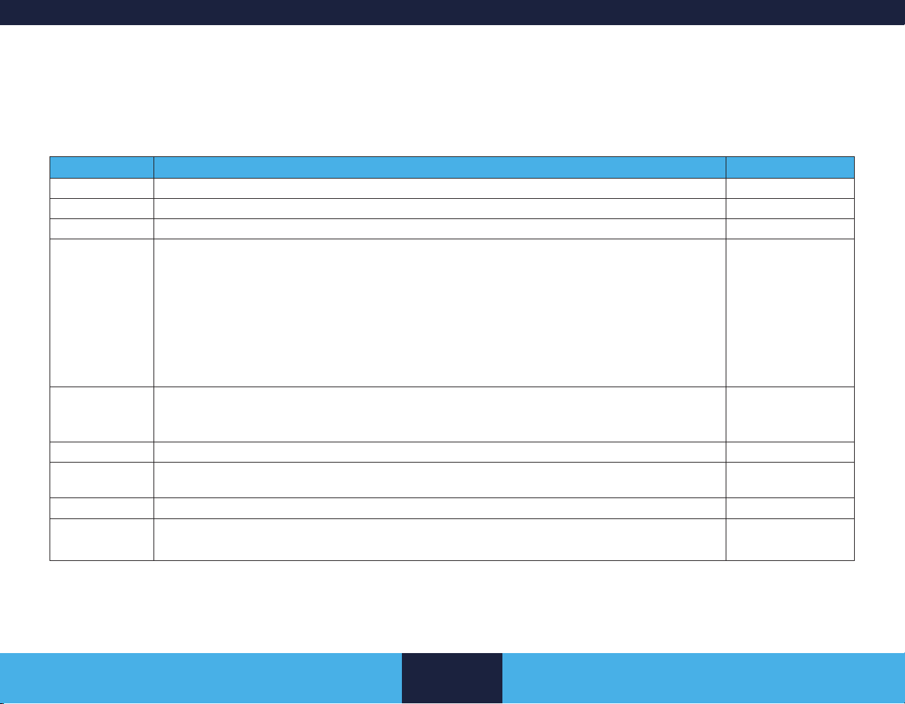
Table 1. Neurostimulator features.
Model
Leads
Electrodes
Groups
Programs/Group
Total Programs
Cycling
SoftStart/Stop
Patient Limits
Adjustment
TargetMyStim
Scheduled Therapy
37022 ENS 4 16 8 4 16 –
37703 / 37704 Itrel 4 1 4 1 1 1 – – – –
37711 Restore 2 16 26 4 32 – – –
37701 RestorePrime 2 16 26 4 32 – – –
37702 PrimeAdvanced 4 16 26 4 32 –
97702 PrimeAdvancedMRI 4 16 26 4 32 –
37712 RestoreUltra 4 16 8 4 16 –
97712 RestoreUltraMRI 4 16 8 4 16 –
37713 RestoreAdvanced 4 16 26 4 32 –
97713 RestoreAdvancedMRI 4 16 26 4 32 –
37714 RestoreSensor 4 16 8 4 16 –
97714 RestoreSensorMRI 4 16 8 4 16 –
Legend: Feature is available. – Feature is not available.
AdaptiveStim
English 2021-04-15
9
Programmable Settings
Page 10

Data Security and Network Connectivity
Data security
The clinician programming system uses and stores data about the
patient's health and implanted medical device. This data is protected
by application-level encryption and encryption provided by the
clinician tablet. The clinician programming system does not provide
data protection for data exported to another destination. Exported
data should be handled in accordance with your facility’s security
policy for data handling and storage.
■ Medtronic recommends that you always save exported data to
the default reports location on the clinician tablet.
disconnecting, and upgrading equipment; upgrading or installing
software; or changing network congurations could also introduce
additional risks. Analyze, evaluate, and control any identied risks.
If you suspect a cybersecurity event has occurred, stop using the app
(if possible) and contact your IT Security team or Medtronic Technical
Services to document and respond to the suspected incident.
If your clinician tablet is lost or stolen, contact Medtronic using the
contact information listed on the back cover of this manual.
Installing application updates
Medtronic periodically updates the therapy app and will not install
updates without notifying you. Network connectivity is required to
update the app. When notied that an app update is available, follow
the instructions provided by Medtronic to install the update.
Network connectivity
Network connectivity is required for initial app registration and for
installation of Medtronic app updates and communicator rmware
updates. Network connectivity is not required for neurostimulator
programming. To protect your clinician programming system,
Medtronic recommends you implement the following security
measures:
■ Secure your clinician tablet by disabling network connectivity
during any programming session.
■ Use a managed, trusted Wi-Fi connection when network
connectivity is needed.
■ Connect the clinician tablet to the network periodically to check
for update notications.
Caution: Connecting the clinician tablet to a network that
includes other equipment could result in unforeseen risks to patients,
operators, or third parties. Changes to your network such as adding,
English 2021-04-15
Installing communicator updates
When notied to install a communicator rmware update, connect the
communicator to the clinician tablet using the USB connector cable.
Follow the instructions provided by Medtronic to install the update.
Returning the clinician tablet
If you need to return the clinician tablet for disposal or replacement,
contact Medtronic using the contact information listed on the back
cover of this manual. Instructions will be provided for preparing the
clinician tablet for return.
10
Data Security and Network Connectivity
Page 11

General Warnings and Cautions
If a serious incident related to the app occurs, immediately report the
incident to Medtronic and the applicable competent authority.
MRI warning for scan eligibility
Warning: For neurostimulators with SureScan MRI Technology
(97702, 97712, 97713, 97714), always program the following
component information:
■ Neurostimulator and lead model numbers
■ Neurostimulator implant location and lead tip location
■ Presence of extensions or abandoned leads
If this information is not up-to-date or is entered incorrectly, MRI scan
eligibility data will be inaccurate, and the patient is at risk for one of
the following:
■ The patient is allowed to have an MRI scan inappropriate for
the implanted components, which could cause tissue heating,
resulting in tissue damage or serious patient injury.
■ The patient is unnecessarily restricted from having an MRI
scan.
For all neurostimulators, refer to the MRI Guidelines for Medtronic
Neurostimulation Systems for Chronic Pain instructions for use
manual for MRI scan eligibility information, MRI scan conditions, and
MRI-specic warnings and cautions for conducting an MRI scan.
on trial stimulation components and may cause heating of the lead
electrodes, resulting in tissue damage or serious patient injury.
Sterile eld warning for
programming components
Warning: To use the programming components (external
and nonsterile) in a sterile eld, place a sterile barrier between the
patient and the programming components to prevent infection. Do
not sterilize any of the programming components. Sterilization may
damage the programming components.
EMI caution for telemetry signal disruption
Caution: Electromagnetic interference (EMI) can disrupt
programming and telemetry communication. If EMI interference
is suspected, such as from radio frequency identication (RFID)
equipment, move away from the likely source of EMI and try again.
Cautions related to clinician programming and possible interactions with other devices
Refer to the Information for Prescribers booklet for cautions related
to clinician programming and possible interactions with other devices
(such as cardiac devices).
MRI warning for trial stimulation
Warning: Physicians should not prescribe MRI for patients
undergoing trial stimulation or who have any neurostimulation system
components that are not fully implanted. Explant all trial stimulation
components if an MRI scan is required. MRI has not been tested
English 2021-04-15
11
General Warnings and Cautions
Page 12

Setting up the Programming System
Clinician tablet with
clinician programmer app
Power button
USB
connector cable Communicator
Power button
Neurostimulator
(ENS or INS)
Finding and opening the app
1. Navigate to the Apps on the clinician tablet.
2. Find the Restore app icon.
3. Tap the Restore app icon to open the app.
Proximal Telemetry
Hold communicator directly
The connector cable is required for pairing
the communicator to the clinician tablet.
After pairing, the communicator and the clinician tablet can
communicate using BLUETOOTH
For wireless communication, make sure the clinician tablet
BLUETOOTH
remains within range.
®
®
wireless technology.
over neurostimulator.
Figure 1. Components of the programming system.
Preparing the clinician tablet
Refer to the Model CT900 Clinician Tablet quick start guide for
instructions on how to turn on the tablet and complete initial setup.
Check the battery level of the clinician tablet.
■ The tablet's battery level is shown on the tablet status bar
(uppermost row on the tablet screen).
■ Recharge the tablet if the battery level is low.
Pairing the communicator to the clinician tablet
Refer to the Model 8880T2 Communicator technical manual for
additional instructions, if needed. Only one communicator can be
paired with a clinician tablet at a time.
1. Connect the USB connector cable to the communicator and
the clinician tablet.
2. Turn on the communicator (slide the power button down, then
release).
3. A message appears on the clinician tablet, which asks
permission to open the Communication Manager when the
USB device is connected:
a. Select to use the USB device by default. This selection
prevents this message from appearing again.
b. Select OK.
4. On the initial app screen, tap CONNECT. When pairing is
complete, the LED light (
a solid green.
Once paired, you can disconnect the USB connector cable. The
communicator and clinician tablet communicate using BLUETOOTH
wireless technology. For wireless communication, make sure the
clinician tablet remains within range.
) on the communicator turns
®
English 2021-04-15
12
Setting up the Programming System
Page 13

Positioning the communicator over the neurostimulator
The communicator uses near-eld magnetic induction communication
(also referred to as "proximal telemetry") to communicate with the
external and implantable neurostimulators. This telemetry requires
close proximity for successful programming.
1. Hold the communicator directly over the neurostimulator,
and position the target symbol (
communicator so that it is centered over and facing the
neurostimulator (Figure 2).
■ The target symbol on the communicator indicates the
location of the internal antenna.
) on the back of the
can attach the neurostimulator directly to the communicator as shown
in Figure 3.
■ Locate the slot on the front of the communicator. Place the
external neurostimulator into the slot, and rotate it so the
output jack faces toward the outer edge of the communicator.
Then attach the trialing cable.
Sterile barrier
Target symbol
Figure 2. Position target symbol on communicator over
neurostimulator (INS shown, patient supine).
Note: For the external neurostimulator, you can either hold the
communicator over the neurostimulator as shown in Figure 2 or you
English 2021-04-15
Figure 3. External neurostimulator attached to communicator.
Note: Avoid placing the communicator directly on a metal surface.
Metal surfaces can interfere with communication between the
communicator and the neurostimulator.
Initiating communication with the neurostimulator
1. On the Search for Device screen, tap FIND DEVICE.
Or
Press the Communicate button (
2. Select the serial number of the neurostimulator you intend to
congure, and tap CONNECT.
13
Setting up the Programming System
) on the communicator.
Page 14

3. After connecting to the neurostimulator, the CURRENT
DEVICE STATUS screen will display.
From this screen, you can select workow options. Refer to the
following sections for workow details:
■ "External Neurostimulator Workows" on page 20.
■ "Implantable Neurostimulator Workows" on page 24.
■ Do not leave the clinician tablet unattended during an active
programming session.
■ When a congured neurostimulator is interrogated, a lead
connectivity test is performed to check for impedance issues.
The patient may feel a stimulation change during the test.
■ If the last programming session was completed with the Model
8840 N'Vision Clinician Programmer, programming changes
Notes:
■ If you have problems establishing communication, refer to
may occur upon interrogation with the app. Refer to Table 2 for
a list of the potential programming changes.
"Communicator and clinician tablet troubleshooting" on page
61.
Table 2. Potential programming changes upon interrogation (if last programmed by N'Vision Clinician Programmer).
Feature Programming Change Notes
Amplitude
Resolution
Patient Limits All programmed patient limits will be set to Custom limit
SoftStart/Stop All groups will be set to the highest SoftStart/Stop value
Cycling On/Off
Times
AdaptiveStim
Technology
Note: Alert messages in the app will provide details of the specic programming changes to the neurostimulator.
Amplitude resolution between 0 V and 10 V will be set
to 0.05 V for all programs.
type.
Lower patient limits will be set to the following minimum
values: Amplitude 0.0 V, Pulse Width 60 μs, Rate 2 Hz.
previously congured in the neurostimulator.
Cycling On/Off times will be set to the highest
programmed values for all groups with Cycling enabled.
For groups with AdaptiveStim enabled, all positions
(except Mobile) will be enabled. If Mobile was
previously enabled, there will be no change to that
position. The position amplitude for newly enabled
positions will be set to 0.0 V.
The patient will have to press the Increase or Decrease key twice
for each change of 0.1 V.
The app only supports Custom limit type and upper limit
customization for patient limits.
Existing values for upper patient limits will not change upon
interrogation.
The app supports a single SoftStart/Stop value for all groups. If
some groups are On and some groups are Off, the setting will
change to On for all groups.
The app supports a single set of Cycling On/Off times for all
groups. Cycling can be enabled/disabled at the group level.
The patient may perceive therapy changes due to the newly
enabled positions. Make sure to review all AdaptiveStim settings
before ending the programming session.
English 2021-04-15
14
Setting up the Programming System
Page 15

Overview of the Clinician Programmer App
Using Demo mode
Use Demo mode to explore the clinician programmer app without
interrogating or updating a neurostimulator.
When the app is in Demo mode, it is not communicating with a real
neurostimulator and does not require the use of a communicator. Any
data displayed in Demo mode are not actual.
Demo mode can be used for training and demonstration purposes
and to familiarize yourself with the app interface before starting an
actual programming session.
1. On the initial app screen, tap DEMO.
2. Select a device, and tap CONNECT.
3. Navigate through the workow. One workow at a time can be
explored in a Demo session.
After you start a workow, a workow navigator appears at the top
of the screen. For example, the Congured ENS: Followup workow
contains these screens:
Device
Electrode Impedance
Lead Select Tip Location Programs
Diaries Reports Summary
■ To move from screen to screen, swipe left or right on the
screen.
■ Alternately, you can tap on the screen name in the workow
navigator to go directly to that screen.
– If the workow navigator extends beyond the width of
the screen, swipe the workow navigator left or right to
show the screens that are clipped off.
■ The current screen is underlined and highlighted.
■ If input is required in a workow screen, you will not be able to
advance to the next screen until you enter the required input.
– The app will prompt you for the required input.
– Red asterisks indicate required elds.
4. To exit Demo mode, go to the Summary screen and tap EXIT
WORKFLOW.
Exiting the workow will return you to the initial app screen
where you can select DEMO again and select another device
to explore.
Navigating through workows
The screens typically used during a programming session are
grouped into workows. The workows vary depending on the device
type (external neurostimulator vs. implantable neurostimulator) and
device status (new vs. congured). The workows may also vary
depending on neurostimulator features, such as SureScan MRI
Technology.
English 2021-04-15
Using the Side Menu
Screens not in the current workow can be accessed from the Side
Menu. For example, the Patient Info screen is in the new device
workow, but not in the congured device workow. To change patient
data in a congured device, you would access the Patient Info
screen from the Side Menu.
■ To access the Side Menu, tap the Side Menu button (
the top left corner on the action bar.
■ Alternately, you can swipe from the left edge of the tablet to
access the Side Menu.
15
Overview of the Clinician Programmer App
) in
Page 16

On-screen help
Help information is available in the clinician programmer app for
workow screens. View the help information to learn how the app
interface works and how to complete tasks on the screen.
■ To display help information, tap the Help button (
right corner on the action bar.
■ Tap the Help button (or tap anywhere on the screen) to close
the help screen.
) in the top
Buttons and indicators on the action bar
An action bar appears at the top of all screens in all workows. Table
3 describes the buttons and indicators that may appear on the action
bar.
Table 3. Buttons and indicators.
Button / Indicator Description
Side Menu button: Tap to access
screens outside of the workow.
(Alternately, you can swipe from the left
edge of the tablet to access the Side
Menu.)
Back button: Tap to close a screen you
accessed from the Side Menu and return
to the previous workow screen.
Demo mode indicator: Appears in the
action bar when in Demo mode.
Button / Indicator Description
Stimulation toggle: Tap to turn
stimulation on or off. Green indicates that
stimulation is on.
Appears in the action bar when at least
one program exists.
AdaptiveStim indicator: Applicable
to neurostimulators with AdaptiveStim
Technology (37714, 97714).
Appears in the action bar when
AdaptiveStim Technology is enabled.
MRI Status indicator: Applicable to
neurostimulators with SureScan MRI
Technology (97702, 97712, 97713,
97714).
Appears in the action bar when
stimulation is off and the device is ready
for an MRI scan.
The MRI Status indicator does not
provide MRI scan eligibility information.
Help button: Tap to display help
information for the current screen.
Tap the Help button (or tap anywhere on
the screen) to close the help screen.
Go to Summary screen button: Tap to
go directly to the Summary screen, and
then exit the workow to properly end the
programming session.
English 2021-04-15
16
Overview of the Clinician Programmer App
Page 17

When the app is placed in the background
When you navigate away from the clinician programmer app while in
a programming session, the app is placed in the background and is
represented as a oating widget on the clinician tablet.
The oating widget is an overlay that oats on top of the screen to
remind you that you are still in a session.
■ Press and drag the oating widget to move it on the tablet
screen.
■ Tap on the oating widget to access the app and resume the
session.
English 2021-04-15
17
Overview of the Clinician Programmer App
Page 18

Overview of the Communicator
The Model 8880T2 Communicator is a non-sterile component used in
conjunction with the clinician tablet and clinician programmer app to
communicate with Medtronic neurostimulators.
Warning: To use the communicator in a sterile eld, place a
sterile barrier between the patient and the communicator to prevent
infection. Do not sterilize any of the programming components.
Sterilization may damage the programming components.
The communicator is handheld and battery-operated. Communication
between the communicator and the clinician tablet can occur
wirelessly using BLUETOOTH
connector cable.
For information on the Model 8880T2 Communicator, including
description, specications, components, instructions for use,
maintenance, and troubleshooting, refer to the Model 8880T2
Communicator technical manual.
Using the USB connector cable
The following situations require the use of the USB connector cable:
■ First-time pairing of any communicator with a clinician tablet.
■ Firmware updates to the communicator.
■ Environments where multiple devices are using BLUETOOTH
wireless technology and thereby creating interference.
■ Environments where BLUETOOTH
prohibited.
®
technology or wired using the USB
®
wireless technology is
Checking battery status of the communicator
Check the battery status of the communicator before a programming
session and regularly during a programming session. When you turn
on the communicator, a battery LED indicator displays on the top right
side of the communicator.
■ Solid Green: Communicator has been turned on. Battery level
is acceptable and all communicator functions are enabled.
■ Solid Amber: Communicator has been turned on. Batteries
should be replaced soon.
■ Flashing Red: Communicator has been turned on. Batteries
should be replaced immediately. Communicate button (
is disabled.
When the communicator is paired to the clinician tablet, swipe down
from the top of the tablet to view the following during a programming
session:
■ The battery level of the communicator.
■ The status of the connection between the communicator and
the clinician tablet.
®
)
English 2021-04-15
18
Overview of the Communicator
Page 19

Communicator icons on the tablet status bar
Table 4 describes the icons that appear in the tablet status bar
(uppermost row on the tablet screen) indicating the status of the
connection between the communicator and the clinician tablet.
Table 4. Communicator icons in the tablet status bar.
Communicator Icon Description
The communicator is in the process of
connecting to the clinician tablet.
The communicator is communicating
with the clinician tablet via the USB
connector cable.
The communicator requires the USB
connector cable to communicate with the
clinician tablet.
The communicator is communicating
with the clinician tablet using
BLUETOOTH
®
wireless technology.
English 2021-04-15
19
Overview of the Communicator
Page 20

External Neurostimulator
Workows
When an external neurostimulator (ENS) is interrogated, the clinician
programmer app determines if the ENS is new or congured. An ENS
is identied as 'new' if it is in shelf state or if it has been cleared for
re-use. An ENS is identied as 'congured' if it has patient data stored
in it. Based on the status of the ENS, the clinician programmer app
automatically presents the applicable workow options.
New ENS:
■ Start Usage > Start Evaluation workow – go to page 20.
Use at the start of a trial period, when the leads are implanted
and the ENS is connected.
Use for testing lead placement.
Congured ENS:
■ Followup workow – go to page 22.
Use at followup sessions with the patient during the trial period.
■ End Evaluation workow – go to page 23.
Use at the last followup session with the patient at the end of
the trial period.
Use to clear the ENS for re-use.
Notes:
■ To display on-screen help information, tap the Help button (
■ The screens typically used during a programming session are
shown in the workow navigator. Additional screens not in the
current workow can be accessed from the Side Menu (
■ Unsaved information may be lost if the application is improperly
terminated during a programming session. To end a session,
go to the Summary screen and tap the EXIT WORKFLOW
).
button. Ending a session generates a complete session record
that is stored in a database on the clinician tablet.
New ENS: Start Usage > Start
Evaluation workow
1. On the CURRENT DEVICE STATUS screen, conrm that the
device information corresponds with the intended ENS.
2. Tap START USAGE.
This action sets the In Use Date to the current date.
3. Under START EVALUATION, tap START.
4. You are now in the New ENS: Start Evaluation workow.
Use Table 5 to guide you through the screens and tasks in the
workow.
).
English 2021-04-15
20
External Neurostimulator Workows
Page 21

Table 5. New ENS: Start Evaluation workow.
Screen Tasks More information
Device Check the battery status of the neurostimulator. Page 28
Patient Info Enter patient information. Page 28
Lead Select Select the implanted leads. Select a lead from the scrollable drop-down list, and then drag and drop
it at the appropriate electrode numbers. Tap UPDATE to save the data.
Ensure leads are properly connected to the neurostimulator, and then check connectivity by tapping
the CHECK CONNECTIVITY button.
Tip Location Indicate whether extensions are implanted. Page 29
Programs (and
subscreens)
Create programs in groups. Tap a group to make it active. A highlighted box around a group indicates
the group is active. Tap the plus sign to add a program within a group.
Program subscreen: Assign the electrode conguration for the lead(s). Assign pulse width, rate,
and amplitude.
Lead Manipulation subscreen (only applicable if more than one lead): Use to represent the
relative positioning of the implanted leads as viewed from the patient’s back.
Energy subscreen: Set parameters for SoftStart/Stop and cycling. Page 35
Patient Access subscreen: Assign the stimulation parameters that the patient can adjust. Page 36
Electrode
Impedance
Measure electrode impedance.
These measurements verify the integrity of lead, extension, and connector pathways. They may
provide information about lead problems (such as lead breakage, short circuit, open circuit).
Group
Impedance
Measure group (therapy) impedance.
These measurements provide documentation that the pathways are intact and the current provided
is sufcient for the selected therapy.
Summary Conrm that the therapy settings shown are what is intended for the patient.
End the session properly by tapping the EXIT WORKFLOW button.
Page 28
Page 29
Page 30
Page 30
Page 34
Page 39
Page 41
--
English 2021-04-15
21
External Neurostimulator Workows
Page 22

Congured ENS: Followup workow
1. On the CURRENT DEVICE STATUS screen, conrm that the
patient and device information corresponds with the intended
patient and ENS.
2. Under FOLLOWUP, tap START.
3. You are now in the Congured ENS: Followup workow.
Use Table 6 to guide you through the screens and tasks in the
workow.
Table 6. Congured ENS: Followup workow.
Screen Tasks More information
Device Check the battery status of the neurostimulator. Page 28
Lead Select Review the information, and make any updates. Updates may delete programming. Page 28
Tip Location Review the information, and make any updates. Page 29
Programs (and
subscreens)
Electrode
Impedance
Diaries View the Stimulation Usage and Group Usage diaries to assess the patient’s use of the therapy. Page 54
Reports Select a report to view, download, or delete. Page 55
Summary Conrm that the therapy settings shown are what is intended for the patient.
Review the groups, programs, and settings, and make any updates. Conrm that the active group is
the intended group.
Program subscreen: Assign the electrode conguration for the lead(s). Assign pulse width, rate,
and amplitude.
Lead Manipulation subscreen (only applicable if more than one lead): Use to represent the
relative positioning of the implanted leads as viewed from the patient’s back.
Energy subscreen: Set parameters for SoftStart/Stop and cycling. Page 35
Patient Access subscreen: Assign the stimulation parameters that the patient can adjust. Page 36
Measure electrode impedance.
These measurements verify the integrity of lead, extension, and connector pathways. They may
provide information about lead problems (such as lead breakage, short circuit, open circuit).
End the session properly by tapping the EXIT WORKFLOW button.
Page 30
Page 30
Page 34
Page 39
--
English 2021-04-15
22
External Neurostimulator Workows
Page 23

Congured ENS: End Evaluation
workow
1. On the CURRENT DEVICE STATUS screen, conrm that the
patient and device information corresponds with the intended
patient and ENS.
2. Tap END EVALUATION > START.
3. You are now in the Congured ENS: End Evaluation
workow. Use Table 7 to guide you through the screens and
tasks in the workow.
Table 7. Congured ENS: End Evaluation workow.
Screen Tasks More information
Device Check the battery status of the neurostimulator. Page 28
Lead Select Review the information, and make any updates. Updates may delete programming. Page 28
Tip Location Review the information, and make any updates. Page 29
Programs Review the groups, programs, and settings, and make any updates. Page 30
Diaries View the Stimulation Usage and Group Usage diaries to assess the patient’s use of the therapy. Page 54
Reports Select a report to view, download, or delete. Page 55
Clear Device Clear the patient and programming information from the device. This action prepares the external
neurostimulator for re-use.
Summary End the session properly by tapping the EXIT WORKFLOW button. --
Page 29
English 2021-04-15
23
External Neurostimulator Workows
Page 24

Implantable Neurostimulator
Workows
When an implantable neurostimulator (INS) is interrogated, the
clinician programmer app determines if the INS is new or if it has
been previously congured. Based on the status of the INS, the
clinician programmer app automatically presents the applicable
workow options.
New INS:
■ Start Usage > Implant Device workow – go to page 24.
Use when a new INS is being congured (programmed) for the
rst time.
Congured INS:
■ Followup workow – go to page 26.
Use at followup sessions with the patient.
■ View MRI workow – go to page 27.
The View MRI workow is only applicable to neurostimulators
with SureScan MRI Technology (97702, 97712, 97713, 97714).
Use to determine MRI scan eligibility and prepare a patient's
neurostimulation system for an MRI scan.
Notes:
■ To display on-screen help information, tap the Help button (
■ The screens typically used during a programming session are
shown in the workow navigator. Additional screens not in the
current workow can be accessed from the Side Menu (
■ Unsaved information may be lost if the application is improperly
terminated during a programming session. To end a session,
go to the Summary screen and tap the EXIT WORKFLOW
button. Ending a session generates a complete session record
that is stored in a database on the clinician tablet.
New INS: Start Usage > Implant
Device workow
You can initiate communication with the INS in the package before
it is moved into the sterile eld. Tasks such as checking the battery
status and entering device and patient information can be performed
without removing the INS from the package.
1. On the CURRENT DEVICE STATUS screen, conrm that the
device information corresponds with the intended INS.
2. Tap START USAGE.
This action takes the neurostimulator out of shelf state and
sets the In Use Date/Implant Date to the current date. For
rechargeable neurostimulators, this action starts a clock inside
the neurostimulator that determines the date when the Elective
Replacement Indicator (ERI) and End Of Service (EOS)
messages appear.
The In Use Date and Implant Date are the same date. The
In Use Date is shown on the CURRENT DEVICE STATUS
screen, and the Implant Date is shown on the About System
screen. You can change the Implant Date on the About
System screen, but it will not impact the clock inside the
neurostimulator that determines ERI and EOS.
).
).
3. Under IMPLANT DEVICE, tap START.
4. You are now in the New INS: Implant Device workow. Use
Table 8 to guide you through the screens and tasks in the
workow.
English 2021-04-15
24
Implantable Neurostimulator Workows
Page 25

Table 8. New INS: Implant Device workow.
Screen Tasks More information
Device Check the battery status of the neurostimulator. Page 28
Select the implant location. Page 28
Patient Info Enter patient information. Page 28
Lead Select Select the implanted leads. Select a lead from the scrollable drop-down list, and then drag and drop
it at the appropriate electrode numbers. Tap UPDATE to save the data.
Ensure leads are properly connected to the neurostimulator, and then check connectivity by tapping
the CHECK CONNECTIVITY button.
Tip Location Indicate whether extensions are implanted. Indicate whether abandoned leads remain implanted (for
MRI models only). Select the tip location for each lead (for MRI models only).
(This screen is not supported for Itrel 4.)
Programs (and
subscreens)
Create programs in groups. Tap a group to make it active. A highlighted box around a group indicates
the group is active. Tap the plus sign to add a program within a group.
Program subscreen: Assign the electrode conguration for the lead(s). Assign pulse width, rate,
and amplitude.
Lead Manipulation subscreen (only applicable if more than one lead): Use to represent the
relative positioning of the implanted leads as viewed from the patient’s back.
Energy subscreen: Set parameters for SoftStart/Stop and cycling. Page 35
Patient Access subscreen: Assign the stimulation parameters that the patient can adjust. Page 36
Electrode
Impedance
Measure electrode impedance.
These measurements verify the integrity of lead, extension, and connector pathways. They may
provide information about lead problems (such as lead breakage, short circuit, open circuit).
Group
Impedance
Measure group (therapy) impedance.
These measurements provide documentation that the pathways are intact and the current provided
is sufcient for the selected therapy.
Summary Conrm that the therapy settings shown are what is intended for the patient.
End the session properly by tapping the EXIT WORKFLOW button.
Page 28
Page 29
Page 29
Page 30
Page 30
Page 34
Page 39
Page 41
--
English 2021-04-15
25
Implantable Neurostimulator Workows
Page 26
Congured INS: Followup workow
1. On the CURRENT DEVICE STATUS screen, conrm that the
patient and device information corresponds with the intended
patient and INS.
2. Under FOLLOWUP, tap START.
3. You are now in the Congured INS: Followup workow. Use
Table 9 to guide you through the screens and tasks in the
workow.
Table 9. Congured INS: Followup workow.
Screen Tasks More information
Device Check the battery status of the neurostimulator. Page 28
Lead Select Review the information, and make any updates. Updates may delete programming. Page 28
Tip Location Review the information, and make any updates. (This screen is not supported for Itrel 4.) Page 29
Programs (and
subscreens)
Electrode
Impedance
AdaptiveStim Congure the settings for AdaptiveStim Technology (RestoreSensor models 37714, 97714 only). Page 44
Diaries Select a diary to view from the drop-down list. Diaries provide information on therapy usage. (This
Reports Select a report to view, download, or delete. Page 55
Summary Conrm that the therapy settings shown are what is intended for the patient.
Review the groups, programs, and settings, and make any updates. Conrm that the active group is
the intended group.
Program subscreen: Assign the electrode conguration for the lead(s). Assign pulse width, rate,
and amplitude.
Lead Manipulation subscreen (only applicable if more than one lead): Use to represent the
relative positioning of the implanted leads as viewed from the patient’s back.
Energy subscreen: Set parameters for SoftStart/Stop and cycling. Page 35
Patient Access subscreen: Assign the stimulation parameters that the patient can adjust. Page 36
Measure electrode impedance.
These measurements verify the integrity of lead, extension, and connector pathways. They may
provide information about lead problems (such as lead breakage, short circuit, open circuit).
screen is not supported for Itrel 4.)
End the session properly by tapping the EXIT WORKFLOW button.
Page 30
Page 30
Page 34
Page 39
Page 54
--
English 2021-04-15
26
Implantable Neurostimulator Workows
Page 27

Congured INS: View MRI workow
The View MRI workow is only applicable to neurostimulators with
SureScan MRI Technology (97702, 97712, 97713, 97714).
1. On the CURRENT DEVICE STATUS screen, conrm that the
patient and device information corresponds with the intended
patient and INS.
2. Tap VIEW MRI > START.
3. You are now in the Congured INS: View MRI workow. Use
Table 10 to guide you through the screens and tasks in the
workow.
Table 10. Congured INS: View MRI workow.
Screen Tasks More information
Device Conrm the neurostimulator information and implant location. Page 43
Patient Info Conrm the patient information. Page 43
Lead Select Conrm the implanted lead information. Page 43
Tip Location Conrm the extension, abandoned lead, and tip location information. Page 43
MRI Review the MRI scan eligibility.
Determine whether the patient is eligible for the intended MRI scan.
If patient is eligible, turn stimulation off to prepare the patient’s neurostimulation system for the scan.
Reports Prepare the MRI Report. The MRI Report contains information intended for MRI clinicians about the
MRI scan eligibility of the implanted system.
Summary Conrm that stimulation is off and MRI status shows the device is ready for an MRI scan.
End the session properly by tapping the EXIT WORKFLOW button.
Page 43
Page 43
--
English 2021-04-15
27
Implantable Neurostimulator Workows
Page 28

Working with Device and Patient Information
Checking battery status of the neurostimulator
The battery status for the neurostimulator (ENS or INS) is shown at
the start and at the end of a programming session on the following
screens:
■ CURRENT DEVICE STATUS screen
■ Device screen
■ Summary screen
For all neurostimulators, the battery status is displayed in volts.
For rechargeable neurostimulators, a battery image also displays
representing the battery level percentage: 0%, 25%, 50%, 75%, or
100%.
At the start of a programming session, if the battery voltage is below
25% for a rechargeable neurostimulator or an ENS, a message
noties you that the device is running on low battery.
If the battery voltage for a rechargeable neurostimulator or an ENS
is too low to sustain therapy or a programming session, a message
noties you of the battery issue. You need to either recharge the
battery in the rechargeable neurostimulator or replace the batteries in
the ENS.
For information on battery service life for implanted neurostimulators,
refer to "Elective Replacement Indicator (ERI) message" on page
60 and "End Of Service (EOS) message" on page 60.
Entering implant location
The implant location for implantable neurostimulators is entered
on the Device screen. The Device screen is accessed through the
workow navigator.
■ Select the implant location from the scrollable drop-down list.
Note: For neurostimulators with SureScan MRI Technology (97702,
97712, 97713, 97714), the implant location impacts the MRI scan
eligibility shown on the MRI screen.
Entering patient information
Patient information such as patient name and diagnosis is entered on
the Patient Info screen. The Patient Info screen is accessed through
the workow navigator or by tapping Patient Info on the Side Menu
(
) when the screen is not part of a workow.
■ Enter the applicable patient information. Red asterisks indicate
the required elds.
Entering lead information
The Lead Select screen is used to identify which lead models
are implanted, associate the lead electrode numbering to the
neurostimulator electrode numbering, and check connectivity of the
lead or extension contacts with the neurostimulator contacts. The
Lead Select screen is accessed through the workow navigator.
■ To assign a lead, select the lead model from the scrollable
drop-down list. Press the lead image, and then drag and drop it
at the appropriate electrode numbers of the device.
■ To delete a lead, tap the lead image, and then tap the X that
appears.
■ To change a lead, you must rst delete the current lead, and
then assign a new lead.
English 2021-04-15
28
Working with Device and Patient Information
Page 29

Notes:
■ Make sure the electrode numbering on the screen matches the
electrode numbering of the implanted leads. If necessary, you
can swap leads using the drag-and-drop feature.
■ On surgical leads, the blue box on the lead arm represents
the white marker band on the actual lead. The marker band
indicates the lead arm for electrodes 0-7.
■ For neurostimulators with SureScan MRI Technology (97702,
97712, 97713, 97714), the assigned leads impact the MRI
scan eligibility shown on the MRI screen.
Testing lead connectivity
Once the implanted lead(s) are assigned on the Lead Select screen,
you can check the connectivity of the lead or extension contacts with
the neurostimulator contacts. Prior to running the test, ensure the
leads or extensions are properly connected to the neurostimulator.
■ Tap the CHECK CONNECTIVITY button (
not visible, tap UPDATE on the Lead Select screen to save
the lead data and activate the button.)
– Green electrodes indicate that the lead or extension
contacts have a good connection to the neurostimulator
contacts.
– Red electrodes (with an “X”) indicate a bad connection.
– If there are red electrodes, gently reconnect the leads or
extensions for a better connection to the neurostimulator
contacts. Then repeat the connectivity check.
). (If the button is
Entering extension, abandoned lead, or tip location information
The Tip Location screen is accessed through the workow navigator.
The options on the screen will vary based on the neurostimulator
model being programmed. The screen is not supported for Itrel 4
(37703, 37704).
■ Check the Yes or No checkbox to indicate whether extensions
are implanted.
■ Check the Yes or No checkbox to indicate whether abandoned
leads remain implanted (for MRI models only).
■ Select the tip location for each lead from the scrollable drop-
down list (for MRI models only).
Note: For neurostimulators with SureScan MRI Technology (97702,
97712, 97713, 97714), the abandoned lead, extension, and tip
location information impacts the MRI scan eligibility shown on the MRI
screen.
Clearing information in external neurostimulator for re-use
The Model 37022 External Neurostimulator is a re-usable device.
The Clear Device screen accessed through the Congured ENS:
End Evaluation workow is used to clear the patient and therapy
information from the device and prepare the ENS for re-use.
■ On the Clear Device screen, tap the Clear Device button, and
then conrm the action.
■ A message appears after the device is cleared. Tap OK to end
the session and return to the initial app screen.
The next time the external neurostimulator is interrogated, the device
is identied as a new ENS and the New ENS: Start Usage > Start
Evaluation workow appears.
English 2021-04-15
29
Working with Device and Patient Information
Page 30
Working with Groups and Programs
Programs screen
The Programs screen is used to create, copy, move, and delete
programs within groups and to dene the active group. The
Programs screen is accessed through the workow navigator.
■ Only one group can be active at a time. A highlighted box
around a group indicates the active group.
■ To make another group active, tap that group name.
■ To copy or move a program, press and drag that program to
the intended location, and then select MOVE or COPY from
the message that appears.
■ To delete a program, press and drag that program to the Trash
icon (
)�
■ To create a new program in the active group, tap the add
symbol (+) on the desired program. The Program subscreen
will display where you can assign the program settings.
■ To view the program settings for an existing program, rst
make the group active, and then tap the program to view the
Program subscreen.
Note: For neurostimulators with AdaptiveStim Technology (37714,
97714), the AdaptiveStim indicator (
if AdaptiveStim Technology is enabled for the group.
Program subscreen
The Program subscreen is used to assign, review, and change
program settings for programs in the active group. The Program
) appears next to the group name
subscreen is accessed by tapping a program on the Programs
screen.
■ A line is shown under the program number that is currently
displayed on the Program subscreen.
■ To move from program to program within the active group,
swipe left or right on the screen. Alternately, you can tap a
program number.
■ Use the Program subscreen to assign the electrode
conguration for the leads and to set pulse width, rate, and
amplitude. Refer to "Adjusting Stimulation Parameters" on
page 31.
■ From the Program subscreen, you can access the Lead
Manipulation, Energy, and Patient Access subscreens.
Refer to the following sections for details about these
subscreens:
"Positioning Leads Relative to Implant Location" on page 34.
"Customizing SoftStart/Stop and Cycling" on page 35.
"Enabling Patient Access" on page 36.
Turning stimulation on or off
The Stimulation toggle is found on the action bar at the top-right
corner of the screen. The toggle is available when at least one
program exists. When no programs exist, the area in the action bar
reads “Stimulation Not Setup”.
■ Tap the Stimulation toggle to turn stimulation on (
(
) at any time.
Note: For neurostimulators with SureScan MRI Technology (97702,
97712, 97713, 97714), the MRI Status indicator (
action bar whenever stimulation is off. The MRI Status indicator does
not provide MRI scan eligibility information.
) displays in the
) or off
English 2021-04-15
30
Working with Groups and Programs
Page 31

Adjusting Stimulation Parameters
Stimulation is delivered in electrical pulses. The stimulation
parameters, which include electrode conguration, pulse width, rate,
and amplitude, are attributes of these pulses and can be adjusted to
manage patient therapy.
High-output interlocks
This feature applies to RestoreUltra (37712, 97712), RestoreSensor
(37714, 97714), and ENS (37022).
Certain combinations of high amplitude, pulse width, and rate
settings are not allowed by the clinician programmer app. Highoutput interlocks can prevent certain values and features from being
available for programming. If you attempt to program a parameter
value that will cause the settings to exceed the high-output interlock
limit, the desired parameter value can only be achieved by reducing
one of the other parameter values.
Shared electrodes
This feature applies to RestoreUltra (37712, 97712), RestoreSensor
(37714, 97714), and ENS (37022).
One electrode may be active in more than one program within a
group. When more than one electrode is shared by more than one
program, certain restrictions are applied to prevent rate and pulse
width upper limits from exceeding 260 Hz for rate or 450 μs for pulse
width. The collective rate for a group is calculated by multiplying
the rate assigned to each program by the number of programs in
that group. Shared electrodes appear grayed out on the Program
subscreen when unavailable for programming.
Assigning electrode conguration
Electrode conguration for the leads is assigned on the Program
subscreen.
Electrode conguration must include at least one negative (–) and
one positive (+) electrode. You cannot set amplitude for the program
until you have assigned at least one negative (–) and one positive (+)
electrode to the lead.
■ To assign polarity, tap on the appropriate electrode. Tap once
for negative (–) polarity, twice for positive (+) polarity, or a third
time to remove polarity. Tap Update when nished.
■ To delete an electrode, press and drag that electrode to the
Trash icon (
■ To delete all assigned electrodes, tap the Select All button
(
), and then tap the Trash icon ( ).
■ To move all electrodes at once, tap the Select All button (
and then press and drag the electrodes to a new location on a
lead. This action will set the amplitude to 0 V. The move feature
is not available for Itrel 4 (37703, 37704).
■ To move an individual electrode, you must rst delete the
electrode and then assign a new electrode.
Note: Adding or deleting an electrode after the amplitude is assigned
will reset the amplitude to 0 V by default.
For Itrel 4 (37703, 37704), the neurostimulator can be programmed
to deliver unipolar stimulation (using the neurostimulator case as a
positive electrode). To assign the case as a positive electrode, tap the
'C' on the lead image.
).
),
English 2021-04-15
31
Adjusting Stimulation Parameters
Page 32

Assigning pulse width, rate, and amplitude
Pulse width, rate, and amplitude are assigned on the Program
subscreen.
During a programming session, the selected values for pulse
width, rate, and amplitude are automatically programmed into the
neurostimulator. Once amplitude is set and stimulation is turned on,
the neurostimulator changes stimulation to the new setting every time
a stimulation parameter is changed.
Caution: To prevent possible uncomfortable or unexpected
stimulation (jolting or shocking sensation) during a programming
session, adjust stimulation parameters in small increments above the
perception threshold (the parameter values at which the patient rst
perceives a sensation of stimulation).
Caution: Changing the pulse width or rate in a program may
affect AdaptiveStim therapy. Test each of the AdaptiveStim postures in
the group for appropriate stimulation after making pulse width or rate
changes. Refer to "Testing AdaptiveStim settings" on page 48.
Assigning pulse width
Pulse width is the duration of the pulses in microseconds (μs).
Caution: To prevent possible uncomfortable or unexpected
stimulation (jolting or shocking sensation), decrease the amplitude
to the perception threshold (the amplitude at which the patient rst
perceives a sensation of stimulation) before changing the pulse width.
After changing the pulse width, slowly increase the amplitude.
1. In the Program subscreen, tap PULSE WIDTH to access the
pulse width control.
2. Select the pulse width using any of these controls:
■ Scrollable drop-down list.
■ Dial (press and drag the dot on the dial).
■ Back arrows (
increase.
3. If stimulation is on, the Stop and Jump buttons become
available when the pulse width is increased. Use these
buttons, as needed.
■ Tap the Stop button (
increasing to the new value.
■ Tap the Jump button (
without incremental increases.
) to decrease and forward arrows ( ) to
) to stop stimulation from
) to jump to the new value
Assigning rate
Rate is the frequency of pulses per second, in hertz (Hz). For the
devices that support more than one program in a group, the group
rate is the rate for each program in that group.
1. In the Program subscreen, tap GROUP RATE to access the
rate control.
2. Select the rate using any of these controls:
■ Scrollable drop-down list.
■ Dial (press and drag the dot on the dial).
■ Back arrows (
increase.
) to decrease and forward arrows ( ) to
Assigning amplitude
Amplitude is the strength of the pulse in volts (V). The electrode
conguration for the leads must be assigned before you can set
amplitude.
1. In the Program subscreen, tap AMPLITUDE to access the
amplitude control.
English 2021-04-15
32
Adjusting Stimulation Parameters
Page 33

2. Select the amplitude using any of these controls:
■ Scrollable drop-down list.
■ Dial (press and drag the dot on the dial).
■ Back arrows (
) to decrease and forward arrows ( ) to
increase.
Note: Amplitude increases in increments. When amplitude is
decreased, amplitude decreases immediately to the new value.
3. Use these buttons, as needed:
■ Tap the Stop button (
) to stop stimulation from
increasing to the new value.
■ Tap the Jump button (
) to jump to the new value
without incremental increases.
■ Tap the Amplitude to zero button (
) to immediately
set amplitude to 0 V.
English 2021-04-15
33
Adjusting Stimulation Parameters
Page 34

Positioning Leads Relative to Implant Location
Use the Lead Manipulation subscreen (accessed from the Program
subscreen) to represent the relative positioning of the implanted leads
as viewed from the patient’s back. The subscreen is only applicable if
more than one lead is congured.
■ To swap the relative position of the leads (for example, to
switch the position of lead #2 with lead #1), press and drag a
lead to the location of the other lead.
The positioning of the leads replaces how the leads are shown on the
Programs screen and Program subscreen.
Note: The Lead Manipulation screen is not supported for Itrel 4
(37703, 37704) or for surgical leads.
English 2021-04-15
34
Positioning Leads Relative to Implant Location
Page 35

Customizing SoftStart/Stop and Cycling
Use the Energy subscreen (accessed from the Program subscreen)
to customize the optional device settings for the SoftStart/Stop and
Cycling features. These features are designed to increase patient
comfort and ease of use.
Changing SoftStart/Stop settings
SoftStart/Stop slowly increases the amplitude when stimulation is
turned on and slowly decreases the amplitude when stimulation is
turned off. The slow ramping may feel more comfortable to sensitive
patients.
SoftStart/Stop is assigned at the device level: that is, it is either on
or off for all groups. The SoftStart/Stop feature defaults to “on” with a
duration of 4 seconds.
■ In the Energy subscreen, use the SOFTSTART/STOP drop-
down list to select a duration or to turn SoftStart/Stop off.
If AdaptiveStim Technology and SoftStart/Stop are both enabled
and the amplitude increases or decreases because of a change in
position:
■ The amplitude will slowly increase using the ramping
programmed for SoftStart/Stop.
■ The amplitude will decrease immediately without ramping.
Turning cycling on or off
Cycling turns stimulation on and off at clinician-determined intervals.
Due to a carryover effect, the patient may continue to experience
symptom suppression during the cycling off time. The default setting
for the cycling feature is “off”.
Refer to the System Eligibility, Battery Longevity, Specications
reference manual for information about how cycling affects battery
longevity and recharge intervals.
1. In the Energy subscreen, tap the CYCLING toggle to turn
cycling on (
2. If cycling is on, select the durations for the ON TIME and OFF
TIME intervals.
3. Tap the group name toggle to turn cycling on (
(
) for a specic group. The setting affects all programs in
the group.
Note: Cycling is not available when AdaptiveStim Technology is
enabled for a group.
) or off ( ).
) or off
English 2021-04-15
35
Customizing SoftStart/Stop and Cycling
Page 36

Enabling Patient Access
Use the Patient Access subscreen (accessed from the Program
subscreen) to assign patient controls, if appropriate for the patient.
There are three patient controls on the Patient Access subscreen:
Limits, TargetMyStim, and Adjustment.
Note: The patient controls may vary depending on neurostimulator
model.
Limits
The Limits patient control on the Patient Access subscreen
provides the ability to enable or disable patient control of stimulation
parameters (amplitude, pulse width, group rate). When patient control
is enabled for a stimulation parameter, the patient can adjust that
stimulation parameter using the patient programmer.
If patient control is enabled, the upper patient limit for the stimulation
parameter must be assigned. The lower patient limit is set to the
lowest possible value by default and is not customizable. Patient
control of stimulation parameters is assigned at the group level.
Note: By default, patient control of amplitude is enabled, and patient
control of pulse width and group rate is disabled.
1. Next to the LIMITS heading, make sure that the group you
intend to congure is shown.
2. Tap the toggle next to the stimulation parameter name to
enable (
parameter.
3. For enabled stimulation parameters, set the upper patient limit
using any of these controls:
■ Scrollable drop-down list.
■ Dial (press and drag the dot on the dial).
) or disable ( ) patient control of the stimulation
4. After the patient controls are dened, tap UPDATE.
5. To see the patient control settings for all groups, tap the
OVERVIEW button (
Amplitude
■ The lowest allowable option for the upper patient limit is
determined by the highest amplitude setting in the group's
existing programs.
■ When AdaptiveStim Technology is enabled for a group, patient
control is automatically enabled for amplitude and cannot be
disabled for that group.
Pulse width
■ The lowest allowable option for the upper patient limit is
determined by the highest pulse width setting in the group's
existing programs.
■ When AdaptiveStim Technology is enabled for a group, patient
control is not available for pulse width.
Group rate
■ The lowest allowable option for the upper patient limit is
determined by the current rate setting for the group.
■ When AdaptiveStim Technology is enabled for a group, patient
control is not available for group rate.
Effect of subsequent parameter changes
■ During a subsequent programming session, if a parameter is
increased above the upper patient limit, the upper patient limit
automatically changes to that new value.
).
English 2021-04-15
36
Enabling Patient Access
Page 37

TargetMyStim
Enabling the TargetMyStim patient control on the Patient Access
subscreen allows the patient to move stimulation settings from
electrode to electrode up and down the lead.
1. Under the TARGETMYSTIM heading, make sure that the
group you intend to congure is shown.
2. Tap the group name toggle to enable (
the patient control.
Notes:
■ The TargetMyStim patient control is not supported for Itrel 4
(37703, 37704), Restore (37711), and RestorePrime (37701).
■ TargetMyStim is only available if the following criteria are met:
– The electrode pattern for at least one program in the
group can be moved up or down the lead.
– Amplitude limit is enabled.
– For RestoreSensor (37714, 97714), RestoreUltra
(37712, 97712), and ENS (37022): No program in
the group has a pulse width greater than 450 μs; the
collective rate of all programs in the group is not greater
than 260 Hz; there are no shared electrodes.
■ The TargetMyStim patient control is not available when
AdaptiveStim Technology is enabled for a group.
) or disable ( )
Adjustment
Enabling the Adjustment patient control on the Patient Access
subscreen allows the patient to increase or decrease all program
amplitudes in the active group at the same time.
■ Under the ADJUSTMENT heading, tap the ALL PROGRAMS
TOGETHER toggle to enable (
patient control.
Note: The Adjustment patient control is not supported for Itrel 4
(37703, 37704), Restore (37711), and RestorePrime (37701).
) or disable ( ) the
English 2021-04-15
37
Enabling Patient Access
Page 38

Programming Scheduled Therapy
The Scheduled Therapy feature is used to activate specic groups
at programmed times during a 24-hour period. This feature is not
supported for Itrel 4 (37703, 37704) and RestoreSensor (37714,
97714).
Therapy groups can be scheduled to activate and deactivate
at specic times during a 24-hour period. Each activation and
deactivation of a group is called an event. Up to 8 scheduled events
can be programmed during a 24-hour period. Events cannot overlap,
and only one group can be active at any given time. The minimum
time for an event is 30 minutes.
The Schedule screen is accessed from the Side Menu (
groups available for scheduling are shown in the GROUP list. When
events are scheduled, they display in the DAILY SCHEDULE.
■ To schedule a new event, tap on a group in the GROUP list
and then assign the start and end times in the pop-up window.
(Alternately, you can drag a group from the GROUP list and
drop it on the DAILY SCHEDULE. Then adjust the start and
end times in the pop-up window.)
■ To edit an existing event, tap the event in the DAILY
SCHEDULE, and then adjust the start and end times in the
pop-up window.
(Alternately, you can move an event in the DAILY SCHEDULE
using the drag-and-drop feature.)
■ To remove an existing event, drag the event from the DAILY
SCHEDULE and drop it on the Trash icon (
(Alternately, you can tap an event in the DAILY SCHEDULE,
and then tap the Trash icon (
) in the pop-up window.)
).
). The
■ To turn the Scheduled Therapy feature on or off, use the on/off
toggle (green indicates that Scheduled Therapy is on)�
Note: Scheduled Therapy operation will be suspended during a
programming session to prevent therapy changes from occurring
during the session. When the session is exited, Scheduled Therapy
operation resumes.
English 2021-04-15
38
Programming Scheduled Therapy
Page 39

Checking System Performance
The measurement functions on the Electrode Impedance screen
and Group Impedance screen assist in identifying problems with
system components or the entire implanted system.
Measurements and diagnostic data obtained from the clinician
programmer app are intended to aid in your clinical assessment.
However, as with any electronic system, internal and external factors
can inuence neurostimulator measurements. For example, changes
in lead position can affect the stimulation current or the impedance
measurement. If you obtain a reading that seems inconsistent with
your observations, repeat the measurement.
Before using any measurement functions, please note the following:
■ Measure electrode impedance at the beginning of each
programming session. These measurements verify the
integrity of lead, extension, and connector pathways. They
may provide information about lead problems (such as
lead breakage, short circuit, open circuit). For example,
measurements that show a signicant increase in electrode
impedance can indicate a fractured lead conductor or a loose
setscrew. Conversely, a signicant decrease in electrode
impedance can indicate shorted conductors or a break in lead
insulation. Measurements taken at the beginning of the session
may be useful in interpreting diagnostic data collected since
the previous session.
■ Measure group (therapy) impedance at the end of each
programming session. These measurements provide
documentation that pathways are intact and the current
provided is sufcient for the selected therapy.
Testing electrode impedance
The Electrode Impedance screen is accessed through the workow
navigator or by tapping Impedance on the Side Menu (
part of a workow.
For Restore (37711) and RestorePrime (37701), preset rate,
pulse width, and amplitude values are used during the electrode
impedance test. For all other models, preset rate and pulse width
values are used, and the amplitude value is selectable on the Start
Measurement screen. At the end of the test, the most recently
programmed settings are restored.
1. On the Electrode Impedance screen, tap the MEASURE ALL
IMPEDANCES button (
2. On the Start Measurement screen, select the amplitude value,
if applicable.
3. Tap the START button.
4. After the test is complete, review the impedance results.
Notes:
■ If all impedance values are within range, the message "All
impedances are within normal range" appears in the GOOD
box.
■ If any impedance value is out of range (low or high), the results
appear in the OUT OF RANGE box. Refer to "Troubleshooting
electrode impedance results" on page 40.
■ The impedance value shown for each electrode is measured
with respect to the selected reference electrode. Use the
REFERENCE ELECTRODE scrollable drop-down list to select
a different reference electrode, if applicable.
■ Once an impedance test is performed, results can be viewed
at any time during the programming session by returning to the
).
) when not
English 2021-04-15
39
Checking System Performance
Page 40

Electrode Impedance screen. You can also view or print the
Session Report, which shows the impedance measurements.
troubleshooting electrode impedance results, contact Medtronic using
the contact information listed on the back cover of this manual.
Troubleshooting electrode impedance results
The OUT OF RANGE box on the Electrode Impedance screen
identies where low impedance or high impedance was measured in
the system. The example in Figure 4 shows both low impedance and
high impedance results.
< 50 Ω
13–15
> 10000 Ω
0: 14
1: 14
2: 14
3: 14
4: 14
5: 14
6: 14
7: 14
8: 14
9: 14
10: 14
11: 14
12: 14
13: 14
14: 0, 1, 2, 3, 4, 5, 6, 7, 8, 9, 10, 11, 12, 13, 15
15: 14
Figure 4. Example of out-of-range electrode impedance results.
In this example, a low impedance value was measured for the
electrode pair 13–15, and high impedance values were measured
for several electrode pairs with electrode 14 common to those pairs.
Electrode 14 is likely the electrode causing the high impedance issue.
Refer to the troubleshooting details for high impedance and low
impedance on the following pages. For further assistance with
High impedance troubleshooting
High impedance suggests a possible open circuit in the system.
High impedance for Restore (37711) and RestorePrime (37701):
>3,600 ohms
High impedance for all other models:
■ At 0.25 V: >4,000 ohms
■ At 0.70 V: >10,000 ohms
■ At 1.50 V: >20,000 ohms
■ At 3.00 V: >40,000 ohms
Follow these steps to troubleshoot high impedance values:
1. If applicable, perform the test again at the next highest
amplitude up to 3.00 V (if within the patient's comfort range).
2. If impedance values remain high, consider these
troubleshooting options:
■ Assess whether therapy can be achieved using other
electrodes.
■ Check for misprogrammed information. For example,
check the Lead Select screen to ensure the electrode
numbering on the screen matches the electrode
numbering of the implanted lead(s).
■ Consider using x-ray to inspect the system components
for disconnects or damage.
3. If troubleshooting measures fail to resolve the high impedance
values, consider replacing system components as needed.
English 2021-04-15
40
Checking System Performance
Page 41

Low impedance troubleshooting
Low impedance suggests a possible short circuit in the system that
can lead to rapid battery depletion or inadequate therapy. Do not use
electrodes with a low impedance.
Low impedance for Restore (37711) and RestorePrime (37701):
<70 ohms
Low impedance for all other models:
■ At 0.25 V: <50 ohms
■ At 0.70 V: <50 ohms
■ At 1.50 V: <50 ohms
■ At 3.00 V: <150 ohms
2. The stimulation parameter ranges to be tested display on
the Start Measurement screen. Tap the START button after
conrming the values.
3. Review the impedance and stimulation current results. Refer to
"Troubleshooting group impedance results" on page 41.
Notes:
■ The neurostimulator reports current measurement values as
current delivered during the stimulation pulse.
■ Once an impedance test is performed, results can be viewed
at any time during the programming session by returning to
the Group Impedance screen. You can also view or print the
Session Report, which shows the impedance measurements.
Testing group impedance
The Group Impedance screen is accessed through the workow
navigator or by tapping Impedance on the Side Menu (
part of a workow.
Group (therapy) measurements are impedance and stimulation
current measurements taken at the programmed settings for each
program in a selected group.
Caution: During the group impedance test, stimulation changes
to the parameter values for each program as the impedance is
measured for the group. This may affect patient stimulation while the
test is in progress. You may need to decrease stimulation parameters
to avoid patient discomfort.
1. On the Group Impedance screen, tap the group name you
want to test, and then tap the MEASURE IMPEDANCES
button (
).
English 2021-04-15
) when not
Troubleshooting group impedance results
When impedance results are in the normal range, the impedance
value (in ohms) and the stimulation current (in milliamps) display on
the Group Impedance screen. Normal impedance ranges are:
■ 70 to 3,600 ohms for Restore (37711) and RestorePrime
(37701)
■ 50 to 4,000 ohms for all other models
When impedance results are outside of the normal range, an indicator
displays (either < ## Ω or > #### Ω) where the value is the low or
high range threshold for the neurostimulator. Perform an electrode
impedance test to help determine the likely cause of the circuit
problem. Refer to "Testing electrode impedance" on page 39.
Notes:
■ If an impedance result is not available or out-of-regulation
occurs, the message "HIGH AMPLITUDE" displays. Decrease
41
Checking System Performance
Page 42

stimulation parameters or reduce the number of electrodes for
that program, and then repeat the measurement.
■ If a program amplitude is too low for testing, the message
"LOW AMPLITUDE" displays. Increase the amplitude for
that program, and then repeat the measurement. Minimum
amplitude values are:
– 0.24 V for Restore (37711) and RestorePrime (37701)
– 0.25 V for all other models
English 2021-04-15
42
Checking System Performance
Page 43

Preparing System for an MRI Scan
Refer to the MRI Guidelines for Medtronic Neurostimulation Systems
for Chronic Pain instructions for use manual for the MRI conditions
and MRI-specic warnings and cautions for conducting an MRI scan.
■ Stimulation must be off during an MRI scan.
■ To turn stimulation off, use the Stimulation toggle (
the action bar. Gray indicates that stimulation is off.
View MRI workow
The View MRI workow is only applicable to neurostimulators with
SureScan MRI Technology (97702, 97712, 97713, 97714).
1. On the Device, Lead Select, and Tip Location screens,
conrm that the following component information is complete
and accurate:
■ Neurostimulator and lead model numbers
■ Neurostimulator implant location and lead tip location
■ Presence of extensions or abandoned leads
This information impacts the MRI scan eligibility shown on the
MRI screen.
2. On the Patient Info screen, conrm that the patient information
is complete and accurate.
3. On the MRI screen, review the MRI scan eligibility.
) on
5. To prepare the device for an MRI scan, turn stimulation off
using the Stimulation toggle (
indicates that stimulation is off.
6. Conrm that the message “Device ready for MRI scan”
displays in the status area and the MRI Status indicator (
displays in the action bar.
7. On the Reports screen, select MRI Report from the dropdown list. Refer to "Working with Reports" on page 55 for
details about viewing and printing reports.
Note: If printing capabilities are not available, you can
manually complete the MRI Eligibility Form in the MRI
Guidelines for Medtronic Neurostimulation Systems for Chronic
Pain instructions for use manual.
8. Inform the patient of the following:
■ Stimulation must be off during the MRI scan.
■ Because stimulation is off, pain symptoms may return.
■ Bring the most up-to-date patient ID card to all MRI
appointments.
■ Bring the patient programmer to all MRI appointments.
■ After the MRI scan is complete and the patient is outside
of the magnet room, stimulation can be turned back
on using the patient programmer. Or, if appropriate,
the patient can revisit the clinician after the MRI scan
to have stimulation turned back on with the clinician
programmer app.
) on the action bar. Gray
)
4. Determine whether the patient is eligible for the intended
MRI scan. Do not proceed if eligibility cannot be determined.
Contact your Medtronic representative, if needed.
English 2021-04-15
9. Give the MRI Report to the patient or send the report to the
MRI center.
The MRI clinician uses the MRI Report to conrm the
neurostimulator model, session date, patient information, and
MRI scan eligibility of the patient’s implanted system.
43
Preparing System for an MRI Scan
Page 44
AdaptiveStim Technology
The RestoreSensor neurostimulators with AdaptiveStim Technology
(37714, 97714) can be programmed to adjust amplitude automatically
when the patient changes body position. Amplitude settings can be
assigned to the following positions:
■ Upright
■ Mobile
■ Lying Front
■ Lying Back
■ Lying Right
■ Lying Left
When AdaptiveStim Technology is turned on for a patient, the
neurostimulator automatically adjusts the amplitude based on the
patient's body position and the clinician-programmed settings. If the
patient makes an amplitude adjustment with the patient programmer,
the neurostimulator associates the new amplitude with the patient's
body position as long as the patient stays in that position for at
least three minutes. The next time the patient enters that position,
the neurostimulator will return to the new amplitude. In this way,
AdaptiveStim Technology can respond to patient feedback.
To accommodate the individual needs of the patient, the following
AdaptiveStim settings can be adjusted by the clinician:
■ Position angles: The range or area of a position.
■ Transition times: The amount of time that must elapse after
moving into a new position (and remaining in the new position)
before the amplitude will change.
■ Mobility rate: The intensity of movement that is considered a
change from the stationary position of Upright to the moving
position of Mobile.
Caution regarding cervical location
Caution: The use of AdaptiveStim Technology associated with
position changes in the cervical location has not been shown to be
safe and effective. The use of AdaptiveStim Technology associated
with position changes for locations outside of the thoracic or lumbar
spine may result in unintended stimulation.
Caution regarding healing period
Caution: Do not congure AdaptiveStim Technology during
the implant procedure. A four-week healing period is recommended
after implanting the neurostimulator to allow time for the implanted
components to stabilize. If the tissue around the neurostimulator is
not sufciently healed, movement of the neurostimulator is possible
and may affect orientation.
Conguring AdaptiveStim
Technology with the wizard
When you congure AdaptiveStim Technology with the setup wizard,
all programmed groups and every position including Mobile are
AdaptiveStim-enabled, no matter what settings were previously
assigned to those groups.
When a group is AdaptiveStim-enabled, the AdaptiveStim indicator
(
) appears next to the group name on the Programs screen, and the
following programming features are not available for that group:
■ Patient access for rate
■ Patient access for pulse width
■ Cycling
■ TargetMyStim
English 2021-04-15
44
AdaptiveStim Technology
Page 45

Note: Amplitude limit is automatically enabled when AdaptiveStim
Technology is congured for a group and cannot be disabled for that
group.
1. Go to the Programs screen, and tap a group name to activate
the group you want to congure.
2. Select AdaptiveStim in the workow, and tap CONFIGURE to
start the setup wizard.
3. Follow the on-screen instructions for all applicable positions.
■ On the orientation screen, have the patient get in the
position and tap NEXT to complete the orientation.
Note: You can tap SKIP to bypass certain positions.
Orientation still occurs for the position and a position
amplitude of zero is assigned to that position.
■ On the programming screen, tap the program number
you want to congure, and then set the position
amplitude using the amplitude control. Refer to
"Assigning amplitude" on page 32.
■ If applicable, tap another program number, and then set
the position amplitude. When nished, tap NEXT to go
to the next position.
position amplitudes for that group. You also have the option to
reorient patient positions.
1. Go to the Programs screen, and tap a group name to activate
the group you want to recongure.
2. Go to the AdaptiveStim screen, tap the Settings button (
and then tap Congure.
3. Tap Start Over.
4. (Optional) Tap the Reorient checkbox if you also want to
reorient the neurostimulator to the patient positions.
5. Tap Ye s to proceed.
6. Follow the on-screen instructions to reorient the
neurostimulator to the patient positions (if applicable) and
reassign position amplitudes for the programs in the active
group.
7. When the wizard is nished, a conrmation screen displays
stating that you have successfully recongured AdaptiveStim
Technology for the group.
8. Tap CLOSE to go to the AdaptiveStim screen.
),
4. When the wizard is nished, a conrmation screen displays
stating that you have successfully congured AdaptiveStim
Technology for the group.
5. Tap CLOSE to go to the AdaptiveStim screen.
Reconguring an AdaptiveStimenabled group
If you want to recongure an AdaptiveStim-enabled group, complete
these steps to delete the existing AdaptiveStim settings and reassign
English 2021-04-15
What you can do on the AdaptiveStim screen
The AdaptiveStim screen displays when an AdaptiveStim-enabled
group is the active group and you select AdaptiveStim in the
workow. The AdaptiveStim screen can also be accessed by tapping
AdaptiveStim on the Side Menu (
Refer to Table 11 on page 46 for information about the tasks you
can complete on the AdaptiveStim screen.
45
AdaptiveStim Technology
) when not part of a workow.
Page 46

Table 11. Tasks on the AdaptiveStim screen.
Tasks on the AdaptiveStim screen More information
Review position amplitudes for all AdaptiveStim-enabled groups.
Use this task to view a summary of the position amplitudes for all AdaptiveStim-enabled groups and programs.
Test AdaptiveStim settings.
Use this task to test AdaptiveStim settings during a programming session.
Adjust position amplitudes for individual positions.
Use this task to adjust position amplitudes for individual positions in the active group.
Check patient positions.
Use this task to determine if the neurostimulator correctly detects the patient positions.
Reorient patient positions.
Use this task to reorient the neurostimulator to the patient positions without changing any group settings.
Recongure an AdaptiveStim-enabled group.
Use this task to delete all existing AdaptiveStim settings for a group and reassign position amplitudes. You also have
the option to reorient patient positions.
Disable AdaptiveStim Technology for a group.
Use this task to clear all existing AdaptiveStim settings for a group. All other AdaptiveStim-enabled groups are not
impacted.
Enable or disable AdaptiveStim Technology for the patient.
If enabled, AdaptiveStim Technology and all assigned settings will be on when the programming session ends.
If disabled, AdaptiveStim Technology and all assigned settings will be off when the programming session ends.
However, the patient can turn on AdaptiveStim Technology using the patient programmer.
Turn the Position Trend diary on or off.
The Position Trend diary shows the time the patient spent in each position during the periods between the last four
programming sessions.
Adjust position angles.
Position angle is the range or area of a position and is used to ensure the neurostimulator properly recognizes the
Upright position from the Lying positions.
Adjust transition times.
Transition time is the amount of time that must elapse between changes in position before the amplitude will change.
Page 48
Page 48
Page 48
Page 49
Page 49
Page 45
Page 49
Page 49
Page 50
Page 50
Page 50
English 2021-04-15
46
AdaptiveStim Technology
Page 47

Tasks on the AdaptiveStim screen More information
Adjust mobility rate.
Mobility rate is the intensity of movement that is considered a change from the stationary position of Upright to the
moving position of Mobile.
Turn off mobility detection.
Turning off mobility detection disables the Mobile position for AdaptiveStim Technology.
Troubleshoot AdaptiveStim Technology.
Table 12 lists potential issues that can occur with AdaptiveStim Technology, as well as possible solutions for resolving
those issues.
Page 51
Page 51
Page 51
English 2021-04-15
47
AdaptiveStim Technology
Page 48

Reviewing position amplitudes for all AdaptiveStim-enabled groups
A summary of the position amplitudes for all AdaptiveStim-enabled
groups and programs can be viewed from the AdaptiveStim screen.
1. Go to the AdaptiveStim screen, tap the Settings button (
and then tap Overview.
Adjusting position amplitudes for individual positions
Complete these steps to adjust position amplitudes for individual
positions in a group.
),
1. Go to the Programs screen, and tap a group name to activate
the group you want to adjust.
2. Review the position amplitudes assigned to the AdaptiveStimenabled groups. If all groups and programs are not visible, you
may need to swipe left or right to see all of the data.
3. Tap CLOSE to return to the AdaptiveStim screen.
Testing AdaptiveStim settings
During a programming session, AdaptiveStim settings are suspended.
The Test AdaptiveStim feature can be used to test AdaptiveStim
settings in session and obtain patient feedback. There must be at
least two different position amplitudes dened in a program to run the
test.
1. Go to the Programs screen, and tap a group name to activate
the group you want to test.
2. Go to the AdaptiveStim screen, and tap the TEST
ADAPTIVESTIM button (
3. Follow the on-screen instructions to test the AdaptiveStim
settings and obtain patient feedback.
4. Tap STOP to end the test.
).
2. Go to the AdaptiveStim screen, and tap the position you want
to adjust.
On the screen, you see the current programs in the group.
Within each program box, the program amplitude is displayed
in white and the position amplitude is displayed in blue. A white
box around a program identies the active program.
3. Tap the program number you want to adjust.
4. Use the amplitude control to adjust the program amplitude
(the stimulation the patient is receiving). Refer to "Assigning
amplitude" on page 32.
The white dot represents the program amplitude. As you make
amplitude changes, the white dot moves to reect the current
amplitude.
Note: You can also drag the white dot to assign amplitude.
Stimulation ramps up to the amplitude value.
5. When you nd an acceptable amplitude, tap SET POSITION
AMPLITUDE to assign the stimulation the patient is receiving
as the position amplitude.
The blue dot represents the position amplitude.
6. When nished making adjustments, tap CLOSE to return to the
AdaptiveStim screen.
English 2021-04-15
48
AdaptiveStim Technology
Page 49

Checking patient positions
Complete these steps to determine if the neurostimulator correctly
detects the patient positions.
1. Place the patient in the position you intend to check.
2. Go to the AdaptiveStim screen, and tap the CHECK
POSITION button (
3. Conrm that the position shown on the AdaptiveStim screen
corresponds to the patient's body position.
Note: If the patient is in a position between the Upright and Lying
positions, the app identies the position as Transition Zone.
).
Disabling AdaptiveStim Technology for a group
Complete these steps to clear all existing AdaptiveStim settings for a
group. All other AdaptiveStim-enabled groups will not be impacted.
1. Go to the Programs screen, and tap a group name to activate
the group.
2. Go to the AdaptiveStim screen, and tap the on/off toggle next
to the Settings button (
■ Green indicates that the group is enabled.
■ Gray indicates that the group is disabled.
).
Reorienting patient positions
Complete these steps to reorient the neurostimulator to the patient
positions without changing any group settings.
1. Go to the AdaptiveStim screen, tap the Settings button (
and then tap Congure.
2. Tap Reorient Only.
3. Tap Ye s to clear the current orientation.
4. Follow the on-screen instructions to reorient the
neurostimulator to the patient positions.
5. (Optional) Tap SKIP if you want to bypass a position.
6. When all positions have been reoriented, a conrmation screen
displays.
7. Tap CLOSE to go to the AdaptiveStim screen.
English 2021-04-15
3. Tap UPDATE, and then conrm the disable notication.
Enabling or disabling AdaptiveStim Technology for the patient
),
You can choose to either enable or disable AdaptiveStim Technology
for the patient. If enabled, AdaptiveStim Technology and all assigned
settings will be on when the programming session ends. If disabled,
AdaptiveStim Technology and all assigned settings will be off when
the programming session ends. However, the patient can turn on
AdaptiveStim Technology using the patient programmer.
1. Go to the AdaptiveStim screen, and tap the RESUME on/off
toggle.
■ Green indicates that AdaptiveStim is enabled.
■ Gray indicates that AdaptiveStim is disabled.
2. Tap UPDATE to accept the changes.
49
AdaptiveStim Technology
Page 50

Turning the Position Trend diary on or off
The Position Trend diary shows the time the patient spent in each
position during the periods between the last four programming
sessions. The diary is accessed through the Diaries screen.
By default, the Position Trend diary is turned on when AdaptiveStim
Technology is initially congured or recongured, or when patient
positions are reoriented. If the diary is turned off, from that point,
position data is not saved. If the diary is on and AdaptiveStim
Technology is turned off, position data continues to be tracked.
1. Go to the AdaptiveStim screen, tap the Settings button (
and then tap Settings.
2. On the Options tab, tap the on/off toggle. Green indicates that
the diary is on.
3. Tap UPDATE to accept the changes.
4. Tap CLOSE to return to the AdaptiveStim screen.
3. On the Angles diagram, tap the position name for the angle
you want to adjust (Upright, Lying Back, or Lying Front).
4. Press and drag one of the delimiter dots to set a larger or
smaller angle.
5. Make other adjustments to the position angles as needed.
6. Tap UPDATE to accept the changes.
7. Tap CLOSE to return to the AdaptiveStim screen.
Note: To test the changes, refer to "Testing AdaptiveStim settings" on
page 48.
),
Adjusting transition times
Transition time is the amount of time that must elapse between
changes in position before the amplitude will change. You can adjust
transition times for each position change.
1. Go to the AdaptiveStim screen, tap the Settings button (
and then tap Settings.
),
Adjusting position angles
Position angle is the range of a position and is used to ensure the
neurostimulator properly recognizes the Upright position from the
Lying positions. By default, the Upright position angle is set to X-Small
and the Lying position angle is set to Large. All lying postures (Back,
Front, Left, Right) use the same position angle value. There is a
Transition Zone between the Upright and Lying positions. The size
of the Transition Zone is calculated based on the Upright and Lying
position angles.
1. Go to the AdaptiveStim screen, tap the Settings button (
and then tap Settings.
2. Tap the Angles tab.
English 2021-04-15
),
2. Tap the Transitions tab.
3. Swipe up and down on the screen to scroll and nd the
position change you want to adjust.
4. Tap the scrollable drop-down list and select a duration.
5. Make adjustments to other transition times as needed.
6. Tap UPDATE to accept the changes.
7. Tap CLOSE to return to the AdaptiveStim screen.
Note: To test the changes, refer to "Testing AdaptiveStim settings" on
page 48.
50
AdaptiveStim Technology
Page 51

Adjusting mobility rate
Mobility rate is the intensity of movement that is considered a change
from the stationary position of Upright to the moving position of
Mobile. The mobility rate is only accessible if the Mobile posture is
enabled.
1. Go to the AdaptiveStim screen, tap the Settings button (
and then tap Settings.
2. Tap the Mobility Rate tab.
3. Conrm that the on/off toggle is on. Green indicates that the
Mobile posture is enabled.
4. Press and drag the Mobility Rate dot on the slider.
■ Low (L): Takes less motion for the neurostimulator to
detect the mobile position.
■ High (H): Takes more motion for the neurostimulator to
detect the mobile position.
5. Tap UPDATE to accept the changes.
6. Tap CLOSE to return to the AdaptiveStim screen.
Note: To test the change in mobility rate, refer to "Testing
AdaptiveStim settings" on page 48. To check patient positions, refer
to "Checking patient positions" on page 49.
),
2. Tap the Mobility Rate tab.
3. Tap the on/off toggle. Gray indicates that the Mobile position is
disabled.
4. Tap UPDATE to accept the changes.
5. Tap CLOSE to return to the AdaptiveStim screen.
Troubleshooting AdaptiveStim Technology
Refer to Table 12 on page 52 for a list of potential issues that can
occur with AdaptiveStim Technology, as well as possible solutions for
resolving those issues.
Turning off mobility detection
Turning off mobility detection disables the Mobile position for
AdaptiveStim Technology. When off, the Mobile position button is
dimmed in the AdaptiveStim screen.
1. Go to the AdaptiveStim screen, tap the Settings button (
and then tap Settings.
English 2021-04-15
),
51
AdaptiveStim Technology
Page 52

Table 12. Troubleshooting AdaptiveStim Technology.
Problem Possible Solutions
The delay between a position
change and the amplitude
change is too slow or too fast for
the patient.
The amplitude changes too often
for the patient.
The amplitude changes to the
amplitude for Mobile while the
patient is in the Upright position
but not mobile.
The amplitude does not change
to the amplitude for Mobile when
the patient is moving.
The patient does not like that the
amplitude changes to the Mobile
amplitude when starting to walk
from the Upright position.
Neurostimulator may have
rotated or ipped within the
pocket.
Patient feels the amplitude for
Upright when lying down.
Patient is not getting
adequate therapy in a position
programmed with AdaptiveStim.
■ Use the Transitions setting to increase or decrease the delay between position changes and amplitude
changes.
■ Use the Test AdaptiveStim feature to obtain patient feedback and make adjustments as needed.
■ Use the Angles setting to increase the angle for the position that is changing too often.
Or
■ Use the Transitions setting to increase the delay between position change and amplitude change.
■ Use the Mobility Rate setting to increase the intensity of movement that is required to change to the
amplitude for the Mobile position.
■ Have the patient remain still in the Upright position for at least one minute.
■ Use the Check Position feature to conrm the patient’s position. If “Mobile” is shown instead of
“Upright” for the patient’s current position, increase the mobility rate.
■ Use the Mobility Rate setting to decrease the intensity of movement that is required to change to the
amplitude for the Mobile position.
■ Have the patient walk down the hall for at least one minute.
■ Use the Check Position feature to conrm the patient’s position. If “Upright” is shown instead of
“Mobile” for the patient’s current position, decrease the mobility rate.
■ Turn off the Mobility Rate feature.
■ When the mobility rate is turned off, the Mobile position is no longer enabled for AdaptiveStim
Technology.
■ Reorient the neurostimulator to the patient positions.
■ Use the Angles setting to increase the angle for the Lying positions.
■ Review position amplitudes, and check that the position amplitude is not set to 0 V.
English 2021-04-15
52
AdaptiveStim Technology
Page 53

Problem Possible Solutions
Patient unable to adjust their
rate.
■ Create multiple identical groups by copying the current AdaptiveStim-enabled group. Adjust the rate
for each group to provide the patient with different rates with AdaptiveStim enabled. Provide the
patient guidance on how to change groups.
English 2021-04-15
53
AdaptiveStim Technology
Page 54

Viewing Diaries
The charts accessed from the Diaries screen provide overviews of
how the patient is using the neurostimulator. The Diaries screen is
not supported for Itrel 4 (37703, 37704).
Stimulation Usage
The Stimulation Usage chart shows the patient's stimulation usage
for the last 30 days. The chart displays the stimulation on-time
percentage for each day. The metrics provide the average percentage
of stimulation usage over the last 30 days and the percentage of
stimulation on-time since the last programming session.
Note: If 30 days of stimulation usage data is not available, the
calculations are based on the available number of days.
Adjustments
The Adjustments chart is only applicable to neurostimulators with
AdaptiveStim Technology (37714, 97714). The chart shows the
number of amplitude adjustments made by the patient since the
last programming session. Data is shown for each position and
AdaptiveStim-enabled group.
Resting Trend
The Resting Trend chart is only applicable to neurostimulators
with AdaptiveStim Technology (37714, 97714). The chart shows
the average number of position changes from one lying position
to another during the periods between the last four programming
sessions.
Group Usage
The Group Usage chart displays the percentage of time that each
group was used for the last 30 days or since the last programming
session if less than 30 days.
Position Trend
The Position Trend chart is only applicable to neurostimulators with
AdaptiveStim Technology (37714, 97714). The chart shows the time
the patient spent in each position during the periods between the last
four programming sessions. The default view shows all positions and
the amount of time in percentages.
■ Select a position from the scrollable drop-down list if you want
to view a specic position only.
■ Select Time if you want to see the average amount of time per
day in hours and minutes.
English 2021-04-15
Recharge
The Recharge chart is only applicable to rechargeable
neurostimulators (37711, 37712, 37713, 37714, 97712, 97713,
97714). The chart displays the following information for the last six
recharge sessions:
■ The percentage of battery charge at the start of the recharge
session
■ The percentage of battery charge at the end of the recharge
session
■ The length of the recharge session
■ The recharge session date
The metrics provide the average ending percentage of battery
recharge, the average battery recharge time, the average battery
recharge interval, and the median battery recharge coupling value.
54
Viewing Diaries
Page 55

Working with Reports
The following report types are available from the Reports screen:
■ Session Report: Contains information about the settings
programmed into the neurostimulator during a programming
session as well as therapy usage and system status
information.
■ MRI Report: Applicable to neurostimulators with SureScan
MRI Technology (97702, 97712, 97713, 97714). Contains
information intended for MRI clinicians about the MRI scan
eligibility of the implanted system for the selected patient.
■ Medtronic Data Report: Contains information about the
Medtronic data collected from the neurostimulator. This
report is used by Medtronic personnel when troubleshooting.
To compile a Medtronic Data Report, refer to "Compiling a
Medtronic Data Report" on page 58.
The Reports screen is accessed through the workow navigator or by
tapping Reports on the Side Menu (
You can also tap REPORTS on the initial app screen to view reports
for a patient without having to start a session.
Note: Any report generated in Demo mode is labeled DEMO MODE
at the top of the report.
) when not part of a workow.
4. Tap one of the buttons shown in Table 13.
Table 13. Report buttons.
Button Description
View button – to view the report in PDF format.
This action takes you out of the clinician programmer
app. The app runs in the background and your
session data remains intact.
Share button – to send the PDF report to another
destination.
This action takes you out of the clinician programmer
app. The app runs in the background and your
session data remains intact.
Download button – to download and save the PDF
report on the clinician tablet.
This action saves a PDF le in the default reports
folder on the clinician tablet.
Delete button – to delete the selected patient
session record from the clinician tablet.
When a session record is deleted, the data no longer
exists on the clinician tablet. However, deleting a
session record does not delete any existing PDF les
created from that record and stored on the clinician
tablet.
Using the Reports screen
1. Select a report type from the drop-down list. The default is
Session Report.
2. (Optional) Use the lter options to nd the patient data you
want.
3. Tap the desired patient session record in the scrollable list. The
most recent patient session record appears at the top.
English 2021-04-15
55
Working with Reports
Page 56

Patient Data Service app
The Patient Data Service app manages the storage of patient session
data in a locally stored database on the clinician tablet.
The Patient Data Service app can be used to access or delete patient
session data for any patients whose Medtronic devices have been
programmed using any clinician programmer app on the clinician
tablet.
The Patient Data Service app can also be used to adjust (or disable)
the PDF auto-delete feature, which automatically deletes PDF les
from the default reports folder on the clinician tablet after a designated
amount of time.
Finding and opening the app
1. Navigate to the Apps on the clinician tablet.
2. Find the icon for the Patient Data Service app.
3. Tap the icon to open the app.
Table 14. Patient Data Service buttons.
Button Description
Import button – to import the selected session
record into the Reports screen in the clinician
programmer app.
Refer to "Using the Reports screen" on page 55.
Delete button – to delete the selected patient
session record from the clinician tablet.
When a session record is deleted, the data no longer
exists on the clinician tablet. However, deleting a
session record does not delete any existing PDF les
created from that record and stored on the clinician
tablet.
Deleting multiple patient session records at once
1. In the Patient Data Service app, use the lter options to nd
the patient data you want.
Accessing or deleting a patient session record
1. In the Patient Data Service app, use the lter options to nd
the patient data you want.
2. Tap the desired patient session record in the scrollable list. The
most recent patient session record appears at the top.
3. Tap one of the buttons shown in Table 14.
English 2021-04-15
2. Tap and hold on any record in the results list to activate the
multiple record selection feature.
3. Tap the applicable checkboxes to select all records you want to
delete from the scrollable list.
4. Tap the Trash icon (
records to be deleted is shown next to the icon.
Note: To cancel without deleting records, tap the back arrow in
the upper left corner.
56
Patient Data Service app
) to delete the records. The number of
Page 57

Setting the PDF auto-delete feature
Use the auto-delete feature to automatically delete PDF les stored
on the clinician tablet based on a timeframe you select. The autodelete feature is enabled by default with a preset amount of time.
This feature only deletes PDF les from the default reports folder on
the clinician tablet. It does not affect patient session data stored in the
database.
1. In the Patient Data Service app, tap the Settings button (
2. Select PDF Auto Delete.
3. Select the appropriate auto-delete settings, and then tap
UPDATE.
).
English 2021-04-15
57
Patient Data Service app
Page 58

Viewing System Information
The About System screen is accessed from the Side Menu ( ).
This screen provides the following information:
■ System component information (such as model numbers,
serial numbers, rmware numbers, version numbers) for the
device (ENS or INS), clinician tablet, clinician programmer app,
controller (patient programmer), recharger, and communicator.
Includes the component information for the controller (patient
programmer), recharger, and communicator that most recently
communicated with the neurostimulator or was paired with the
clinician tablet.
■ Trademarks and licenses information.
This screen provides the following capabilities:
■ Ability to change the device date and time for the ENS and
INS.
■ Ability to change the INS implant date.
■ Ability to generate a Medtronic Data Report.
Viewing information about system components
On the About System screen, tap the tab for the component
information you want to view.
Changing device date/time or implant date information
The Device tab on the About System screen shows the device date,
device time, and implant date (for INS models). You can change the
date and time information if needed.
■ Tap the date that you want to change. Use the calendar
selector to select a new date, and then tap outside the
calendar.
■ Tap the time that you want to change. Use the time selector to
select a new time, and then tap outside the time.
Note: Changing the implant date does not impact the clock inside
rechargeable neurostimulators that determines ERI and EOS.
Compiling a Medtronic Data Report
The Medtronic Data Report tab on the About System screen is
used to compile a report containing information about the Medtronic
data collected from the neurostimulator.
■ Tap the COMPILE REPORT button (
Medtronic Data Report. You cannot cancel the action after it is
initiated.
To access previously compiled Medtronic Data Reports, refer to
"Working with Reports" on page 55.
) to compile the
Viewing information about trademarks and licenses
On the About System screen, tap the Licenses tab, and then tap the
button for the information you want to view.
English 2021-04-15
58
Viewing System Information
Page 59

Viewing Alerts
The clinician programmer app displays alerts to inform you of specic
events or changes in the system. There are three levels of alerts in
the clinician programmer app: warning, caution, and information.
When alerts are present, an ALERTS button displays on the screen.
The button shows the number of alerts that need to be acknowledged.
Read and follow the instructions given in the alert.
Working with alerts
■ To view alerts, tap the ALERTS button in the lower left corner
of the screen. Each alert appears in a separate pop-up box.
– Swipe left or right to view individual alerts.
■ To close an alert without dismissing it, tap the X (or anywhere
outside of the alert pop-up box).
■ To dismiss an alert, tap the DISMISS button. The alert will be
marked as a dismissed alert.
■ When all alerts are dismissed, the ALERTS button reads "NO
ALERTS". Those alerts, however, now exist as dismissed
alerts and can still be viewed.
■ To view dismissed alerts, tap the NO ALERTS button, and then
tap the SHOW DISMISSED button.
■ To restore a dismissed alert, tap the RESTORE button.
English 2021-04-15
59
Viewing Alerts
Page 60

Troubleshooting
Approach troubleshooting conservatively. Prior to performing
invasive procedures, ensure that all noninvasive solutions have been
considered. If additional assistance is needed, contact Medtronic
using the contact information listed on the back cover of this manual.
The clinician programmer app displays messages to inform you of
issues in the system. Follow the instructions given in the message.
Data validation error message
During initial interrogation, the app performs a data validation check
to ensure that the data in the neurostimulator is valid and can be
understood. If data is found to be invalid, the app displays a data
validation error message and provides the option to clear the invalid
data.
Power on reset (POR) message
If a power on reset message displays at initial interrogation, this
indicates that one or more POR events occurred since the last
programming session. If a power on reset message displays while in
a current programming session, the session will end and any unsaved
data will be lost.
Out of regulation (OOR) message
An out of regulation (OOR) message indicates that the delivered
amplitude may be lower than the programmed amplitude for the
indicated programs because of low impedance. If an out of regulation
situation occurs, decrease settings or reduce the number of
electrodes for the indicated programs.
Overcharge message
An overcharge message indicates that the battery in a rechargeable
neurostimulator has been overcharged. Upon conrmation of the
message, the session will continue.
Overdischarge message
An overdischarge message indicates that the patient allowed the
battery in a rechargeable neurostimulator to completely discharge,
and telemetry is no longer available from the neurostimulator. Refer
to "Physician Recharge mode" on page 64 for instructions on
restoring the device.
Rapid discharge message
A rapid discharge message indicates that the rechargeable
neurostimulator needs to be recharged at least once a day to provide
24-hour stimulation. This issue may be due to high parameter settings
or reduced battery capacity. Parameter adjustment or neurostimulator
replacement may be needed to increase therapy time between
charges.
Elective Replacement Indicator (ERI) message
When an implanted neurostimulator reaches its recommended
replacement date, a message displays. Refer to the System Eligibility,
Battery Longevity, Specications reference manual for information
about neurostimulator battery longevity.
End Of Service (EOS) message
When an implanted neurostimulator reaches its end of service, a
message displays. At EOS, therapy is not available and the device
English 2021-04-15
60
Troubleshooting
Page 61

must be replaced. Refer to the System Eligibility, Battery Longevity,
Specications reference manual for information about neurostimulator
battery longevity.
Using impedance measurements for troubleshooting
Refer to "Checking System Performance" on page 39.
Communicator and clinician tablet troubleshooting
See Table 15 on page 62 for a list of potential issues that can occur
with the communicator or the clinician tablet, as well as possible
solutions for resolving those issues.
English 2021-04-15
61
Troubleshooting
Page 62

Table 15. Communicator and clinician tablet troubleshooting.
Problem Possible Solutions
The communicator cannot
communicate with the
neurostimulator.
Cannot pair the communicator
with the clinician tablet.
The communicator cannot
communicate wirelessly with
the clinician tablet during a
programming session.
■ The communicator may not be positioned correctly over the neurostimulator.
– Position the target symbol (
facing the neurostimulator.
■ The communicator may be too far away from the neurostimulator.
– Move the communicator closer to the neurostimulator.
■ Metal surfaces can interfere with communication between the communicator and the neurostimulator.
– If the communicator is on a metal table or a metal tray, move the communicator to a nonmetal
surface.
■ There could be radio-frequency (RF) interference.
– Move the communicator closer to the neurostimulator.
■ The communicator may have interrogated a different device.
– Place the communicator directly over the neurostimulator (use a sterile barrier, if applicable) and
tap FIND DEVICE on the clinician programmer app.
When attempting to connect through BLUETOOTH
■ Make sure the communicator is turned on and within range of the clinician tablet. See the 8880T2
Technical Manual for details.
■ Make sure that the BLUETOOTH
Refer to "Communicator icons on the tablet status bar" on page 19 for what the communicator icons
mean when displayed in the tablet status bar.
Possible reasons:
■ You are in an environment where multiple devices are using BLUETOOTH
thereby creating interference.
■ You have moved into an environment where the BLUETOOTH
Possible solutions:
■ Use the USB connector cable to connect the communicator to the clinician tablet.
■ Make sure that the BLUETOOTH
Refer to "Communicator icons on the tablet status bar" on page 19 for what the communicator icons
mean when displayed in the tablet status bar.
) on the back of the communicator so that it is centered over and
®
wireless technology:
®
wireless technology is enabled on the clinician tablet.
®
wireless technology and
®
wireless technology is prohibited.
®
wireless technology is enabled on the clinician tablet.
English 2021-04-15
62
Troubleshooting
Page 63

Problem Possible Solutions
The communicator battery level
is low.
The clinician tablet, the clinician
programmer app, or the
communicator is unresponsive.
The communicator is damaged
or overheats.
If the communicator requires repair, is damaged, or is nonfunctional and a replacement is needed, contact Medtronic using the contact
information listed on the back cover of this manual.
■ Open the battery case and replace the batteries.
– If needed, refer to the instructions for replacing the communicator batteries in the Model 8880T2
Communicator technical manual.
■ After replacing the communicator batteries, the clinician programmer app reconnects with the
communicator using the BLUETOOTH
®
wireless technology and resumes the session.
■ Turn off the power for the clinician tablet or the communicator, then turn the power on.
■ If you continue to have communication problems or cannot use the app to program, contact Medtronic
using the contact information listed on the back cover of this manual.
Use a different communicator:
■ Ensure that the damaged communicator is turned off before using another communicator.
■ If using a replacement communicator prior to starting a programming session, use the USB
connector cable and pair the replacement communicator to the clinician tablet.
– Refer to "Pairing the communicator to the clinician tablet" on page 12.
Or
– If replacing the communicator while in a programming session, use the USB connector cable to
connect the communicator to the clinician tablet and continue with the programming session.
English 2021-04-15
63
Troubleshooting
Page 64

Physician Recharge mode
Physician Recharge mode is only applicable to neurostimulators
that are rechargeable (37711, 37712, 37713, 37714, 97712, 97713,
97714).
If the patient allows the implanted neurostimulator to overdischarge,
telemetry is no longer available from the neurostimulator. The patient
will not be able to charge the neurostimulator battery using the
charging system.
The patient must return to the clinic, and the physician must charge
the neurostimulator battery using the Physician Recharge mode on
the recharger. Typically, the neurostimulator will return to normal
charging mode in less than 60 minutes. If it does not, the process
should be repeated. If the neurostimulator cannot be charged, it must
be replaced.
Notes:
■ If the battery is successfully recharged, it regains functionality
but may require more frequent charging sessions by the
patient.
■ The neurostimulator battery can be restored with the Physician
Recharge mode only twice. If the battery is allowed to
overdischarge a third time, the neurostimulator will reach end
of service.
2. Simultaneously press and hold down the Start key and Audio
key located on the front of the recharger (Figure 5) for 10
seconds. A screen with a 60-minute timer will appear, and
charging begins.
Start key
Audio key
Figure 5. Recharger.
3. Continue charging until the recharger displays a new screen
indicating the battery charge level and charging efciency
(Figure 6).
Performing a physician charging session
Using the Model 37751 Recharger
1. Palpate the patient’s skin to determine the best location
for the charging antenna, and place the antenna over the
neurostimulator.
English 2021-04-15
Figure 6. Screen displaying charge level and charging efciency.
4. Repeat steps 1-3 if the new screen does not appear within 60
minutes.
64
Troubleshooting
Page 65

5. Use the clinician programmer to check settings and to turn
stimulation on.
Using the Model WR9200 Recharger
Note: If the volume on the recharger is turned off, you will be unable
to hear the audio feedback in the following steps. See the manual
that came with the recharger for instructions to change the recharger
volume.
1. Connect the charging dock to a power supply. Place the
recharger on the dock as if to charge the recharger.
2. Palpate the patient’s skin to determine the approximate
location of the neurostimulator.
7. After the reset, the recharger transitions to a special recharging
session that may take up to 60 minutes if the neurostimulator
battery needs to be recovered. Keep the recharger over the
implant until it enters a normal recharging session.
Note: The recharger indicator light will turn green when the
implanted neurostimulator enters a normal recharging session.
8. Check therapy status after performing Physician Recharge and
turn on therapy if necessary.
For instructions on performing a normal recharging session using
the Model WR9200 recharger, see the manual provided with the
recharger.
3. With the recharger on the dock, enter Physician Recharge
mode by using the button press sequence: short, short, long.
You will see the battery indicator ll up and hear a beep with
each button press.
Note: A short button press is 1-2 seconds. A long button press
is 4-6 seconds.
4. The light on the power button indicator will show a spinning
amber light and the recharger will beep.
5. Pick up the recharger from the dock and hold it over the
patient’s implanted neurostimulator. Within 2 minutes, the
power button indicator will show a ashing amber light and
beeping will get faster. This means the recharger is preparing
to reset the neurostimulator.
6. Keep the recharger over the implant after the beeping stops.
The reset will start after the beeping ends and will take up to 1
minute to complete. The recharger indicator light will change to
a slow pulse when the reset has completed.
English 2021-04-15
Patient programmer messages
The patient programmer displays text and iconic error and
informational messages. The applicable messages vary based on
neurostimulator model. Some messages provide an error code and
tell the patients to contact their physician. These error codes and their
troubleshooting procedures are displayed in Table 16.
Table 16. Contact Physician error codes on the patient
programmer.
Error code Explanation
536 Moisture was detected inside the ENS. The ENS
must be dried with a towel, the battery removed, and
the battery compartment allowed to air dry at room
temperature.
537 The Emergency stop key on the ENS is active.
Check the key and replace the device if needed.
574 No programs or groups were saved by the
clinician programmer. The neurostimulator must be
reprogrammed.
65
Troubleshooting
Page 66

Error code Explanation
OOR Out of regulation situation has occurred. Decrease
settings or reduce the number of electrodes.
POR The neurostimulator has undergone a power on
reset. No therapy is available until the device is reactivated.
556/589 The INS battery was overcharged or the wrong
batteries were placed in the ENS. The patient must
come into the clinic, and the clinician programmer
must be used to determine device status.
575/578 Invalid settings were detected in the INS/ENS. The
device must be reset and valid settings entered.
0 to 250 Invalid settings were detected in the patient
programmer. The patient should remove the
programmer batteries and re-insert them after a
few seconds. The error code should disappear. If it
reappears, the patient programmer may need to be
replaced.
English 2021-04-15
66
Page 67

English 2021-04-15
67
Troubleshooting
Page 68

English 2021-04-15
68
Page 69

Manufacturer
Medtronic, Inc.
710 Medtronic Parkway
Minneapolis, MN 55432
USA
www.medtronic.com
Tel. +1-763-505-5000
Authorized Representative
in the European Community
Medtronic B.V.
Earl Bakkenstraat 10
6422 PJ Heerlen
The Netherlands
Tel. +31-45-566-8000
Europe/Africa/Middle East Headquarters
Medtronic International Trading Sàrl
Route du Molliau 31
Case Postale 84
CH - 1131 Tolochenaz
Switzerland
www.medtronic.eu
Tel. +41-21-802-7000
Asia-Pacic
Medtronic International Ltd.
50 Pasir Panjang Road
#04-51 Mapletree Business City
Singapore 117384
Singapore
Tel. +65-6870-5510
*M974907A016*
© Medtronic 2021
All Rights Reserved
2021-04-15
M974907A016 Rev A
 Loading...