


SURGICAL TECHNIQUE
Catalyft™ LS
Expandable Interbody System

Table of contents
1 Implant overview
1 Screw overview
2 Instrument overview
4 Access
5 Templates/Distractors
6 Cage attachment
7 Pre-implantation graft delivery
8 Cage insertion
9 Cage expansion
11 Gr a f t o n™ DBF post-expansion filling the cage
12 Screw fixation
16 Posterior fixation/posterior access to expansion mechanism
17 Explantation
18 Product ordering information
19 Important product information
2

Cage overview
pansion measurements
Ex
Anterior
height
Size Expansion
S 06
S 10
M 06
M 10
L 06
L10
Min. 6 10 9
Max. 11. 5 18 30
Min. 10 14 9
Max. 15.5 22 30
Min. 6 10 8
Max. 11.5 19.5 29
Min. 10 14 8
Max. 15.5 23.5 29
Min. 6 10 7
Max. 11.5 21 29
Min. 10 14 7
Max. 15.5 24.5 29
Lordosis angle
Posterior
height
(mm)
Anterior
height
(mm)
Posterior
height
Lordosis
angle
(degrees)
6mm
edium
M
10mm
Medium
10 –19mm
14–23mm
7-29°
6–11mm
7-29°
10–15mm
Max achievable lordosis angle
is pending height expansion
Footrints
Small
32mm × 25mm
Medium
37mm × 29mm
Screw overview
• Lengths: 25-55mm
• Inner diameter: 3.7mm
• Outer diameter: 5.5mm
• Cancellous thread pitch: 3.2mm
• Cortical thread pitch: 1.6mm
• Self-drilling and self-tapping screws
If the posterior aspect of the
cage is at max expansion, the
greatest possible lordosis
would be 14° for the Small
cage, 15.5° for the Medium,
and 16° for the Large cage.
Large
42mm × 32mm
Cortical
thread
Cancellous
thread
• Dual thread design
1
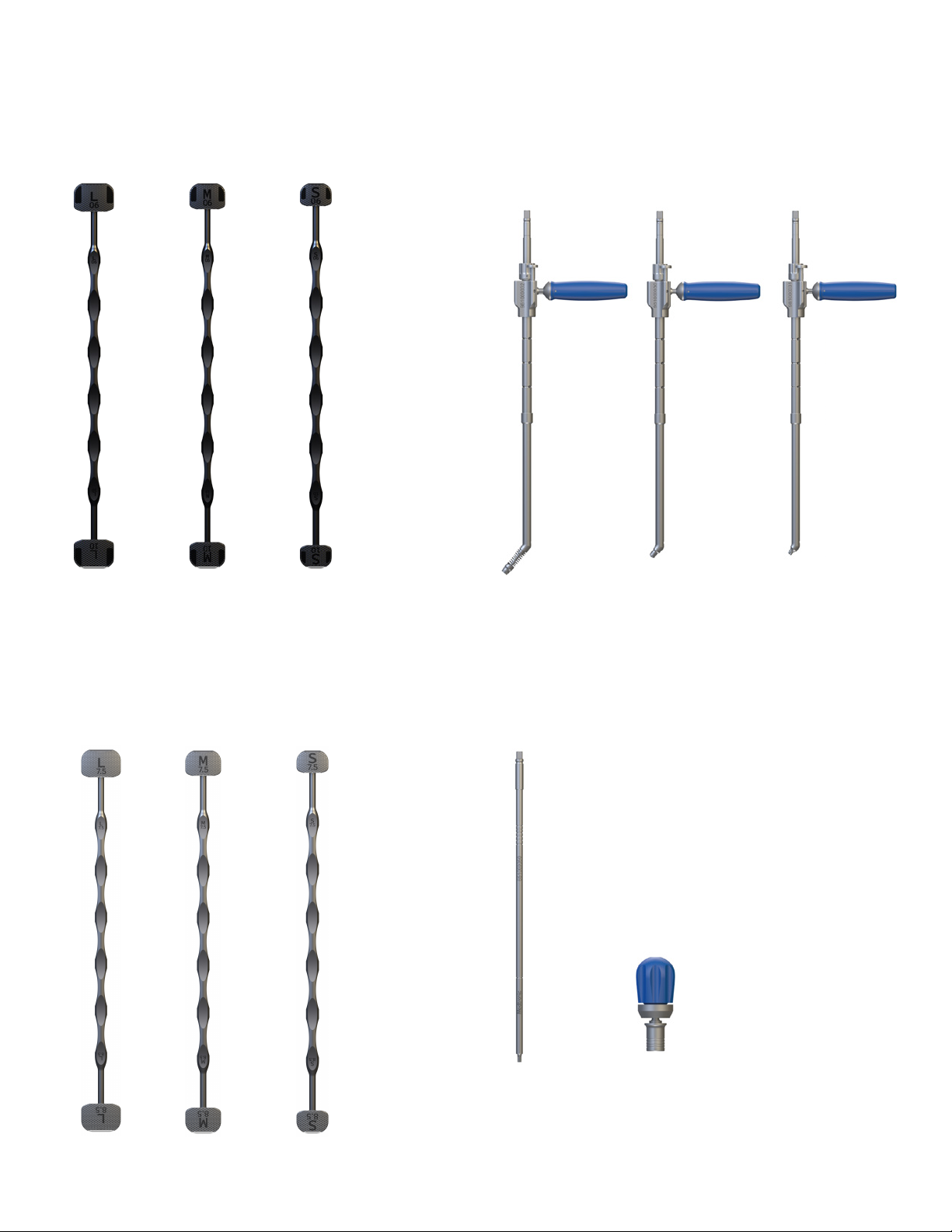
Instrument overview
Templates
Anterior Large
981000027
*
Anterior Medium
981000025
Anterior Small
981000023
*Templates mimic corresponding cage at collapsed state.
Bone Screw Instrumentation
Angled
Drill
98100032
Angled
T25 Screwdriver
981000030
Short
T25 Screwdriver
981000031
Distractors
Anterior Large
981000028
Anterior Medium
981000026
Anterior Small
981000024
T25 Screwdriver
2150100
2
QC Palm Handle
G1700 59
CATA LYFT™ LS EXPANDABLE INTERBODY DEVICE | INSTRUMENT OVERVIEW
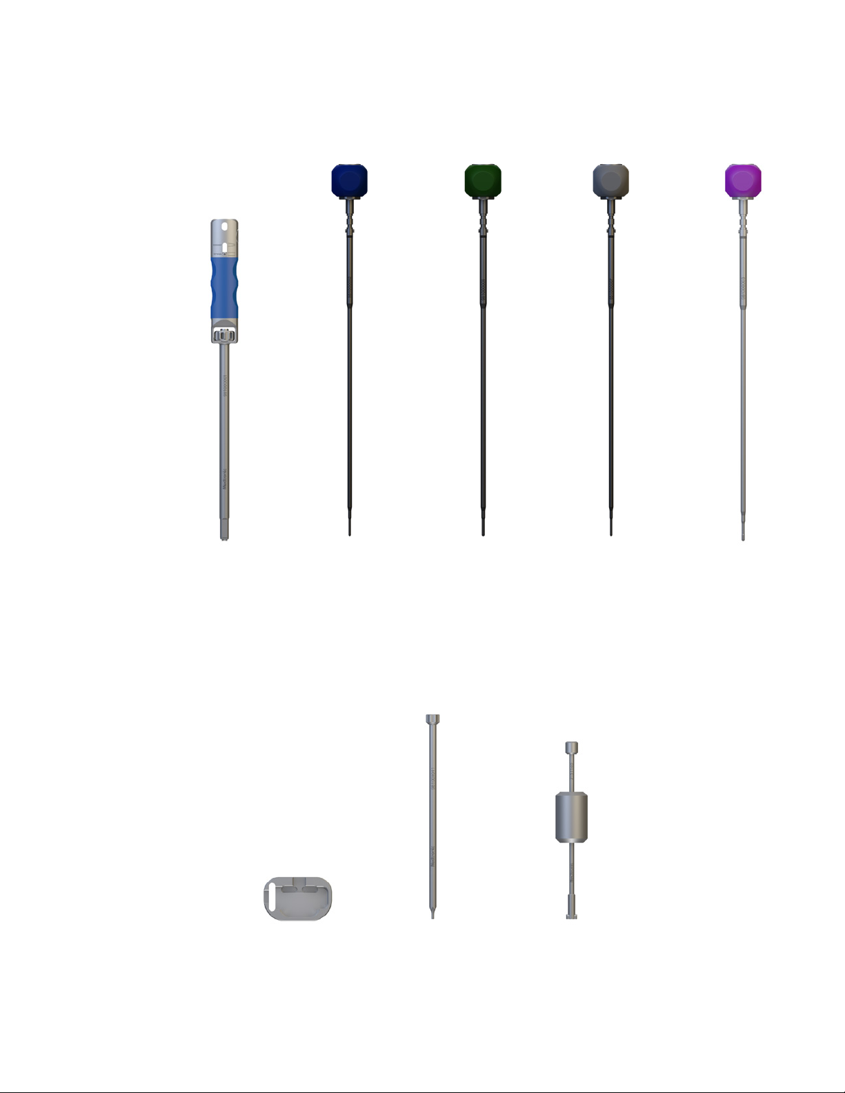
Inserter and Inner Shafts
Inserter
981000001
Lordosis/Parallel Shaft
5Nm
981000002
Bone Graft
Loader
981000040
Lordosis/Parallel
Shaft* 6Nm
981000006
Syringe Adapter
981000041
Lordosis/Parallel Shaft*
7Nm
981000007
*Optional expansion shafts
Slaphammer
215114 0
Anterior/Posterior*
Shaft
981000003
3

Access
Catalyft™ LS expandable
The
interbody system can be used
with an OLIF51™ procedure or an
ALIF procedure, depending upon
the surgeon’s preference and
anatomical considerations. Refer to
the appropriate procedural
surgical technique for access and
disc preparation instructions.
ALIF
procedure
OLIF51™
procedure
4

Templates/Distractors
After the disc space has been
prepared and any osteophytes have
been removed, Templates matching
the cage in a collapsed state are used
to identify the cage's footprint and size
matching the initial anatomy.
Distractors can be used sequentially
to stretch the soft tissues and optimize
the segmental correction by expansion
of the cage in situ. A/P and lateral
fluoroscopy can also be used to
confirm the appropriate cage size and
positioning.
Note
Due to expansion capability of the
cage, the template may fit loosely in
the disc space.
Temp
late
Dist
ractor
5

Cage attachment
After the appropriate cage has been
determined, attach the corresponding
cage to the Inserter. Insert the
Lordosis/Parallel Shaft 5NM 98100002
into the Inserter by pressing down on
the release button on the handle and
fully inserting the shaft into the cannula
of the Inserter until the expansion
indicator is in the "Parallel" expansion
state. Attach the cage to the Inserter
by threading the Inserter into the
female thread of the cage by using the
thumbwheel on the Inserter
and advancing the threads until the
cage is firmly attached to the cage.
When inserting the cage, the Inserter
should be in the parallel expansion
state.
Note
The Inserter can be attached
independently of the orientation of the
cage or handle.
Ensure the cage is in collapsed state
prior to implantation.
6

Pre-implantation graft delivery
Once the correct cage has been
attached to the Inserter, the Bone Graft
Loader can be used to pre-pack the
cage with autogenous bone graft and/
or allograft bone graft comprised of
cancellous and/or corticocancellous
bone, and/or demineralized allograft
bone with bone marrow aspirate. If
using Grafton™ DBF Inject, hydrate the
DBF with BMA according to the mixing
instructions in the Grafton™ DBF Inject
instructions for use.
Note
Refer to the Grafton™ DBF Inject IFU
for handling and preparation steps.
Graft volume guidelines
Part number Description
981023322 Small 06 0.7cc
981023325 Small 10 1.1cc
981025522 Medium 06 1.2cc
981025525 Medium 10 1.8cc
981027722 Large 06 1.7c c
981027725 Large 10 2.5cc
Pre-pack lateral
windows
7

Cage insertion
Insert the cage into the disc space by
gently tapping with the mallet.
Monitoring placement under lateral
and A/P fluoroscopy can ensure proper
placement of the cage. The cage
should be flush with the anterior
portion of the vertebral bodies.
Note
For multi-level constructs, the arrow
laser markings on the cage must face
towards the head of the patient to
ensure there is no screw interference.
Note
It is recommended to not use
excessive force at insertion,
preferring instead to reuse Distractor
to stretch tissues.
8

Cage expansion
Begin with indicator in the "Parallel" position. Rotating
the shaft expands the cage height by equally changing
the anterior and posterior heights. When adequate
height correction is achieved, the shaft can be switched
to "Lordosis" position by pressing the side button of the
Inserter and pulling the Shaft handle.
Then, with the expansion indicator in "Lordosis"
position, rotating the shaft will change the cage lordosis
angle by expanding only the anterior height.
Note
Arrows on the Shaft handle indicate direction for
increasing
Note
Diamond laser marks on Shaft handle help to count
number of turns: one turn will generate approx 1.5mm of
height expansion or approx 5° of lordosis angle.
or decreasing height of cage.
9

Cage expansion
Monitor the expansion using lateral fluoroscopy to ensure
integrity of the vertebral endplates. The Shaft has a built-in
torque limiter that will limit the applied load.
Once the desired segmental correction is achieved,
the Inserter can be disconnected by turning back the
thumbwheel.
Note
To fully expand the cage when bone quality allows,
Shafts with higher torque limiter (6Nm and 7Nm) can be
sequentially used to fine tune the segmental correction,
however, it is recommended to start with the blue Lordosis/
Parallel 5Nm shaft followed by the 6Nm (green) and 7Nm
(gray).
Note
When the cage has not been fully expanded and a more finetuned correction is desired, use the Anterior/Posterior Shaft
981000003 (purple handle) to adjust anterior and posterior
height individually. In "Parallel" position only the posterior
height is adjusted. In "Lordosis" position only the anterior
height is adjusted. Switching Shaft position may require some
wriggling.
Note
If a posterior rod system is already in place, no additional
correction of the spine will be possible by attempting to
expand the cage height. Once the bone screws have been
implanted, no additional correction of the spine will be
possible by attempting to expand the cage height.
10

Grafton™ DBF Inject
post-expansion filling the cage
Once the desired expansion has been achieved, Grafton™ DBF Inject can be
inserted by threading the syringe adaptor into the distal tip of the syringe.
Place the distal tip of the syringe adaptor onto the open features of the cage
above the plate and also in the feature between the screw holes to inject the
bone graft into the cage. The bone graft material must fill the cage fully.
Fluoroscopy can be used for verification.
Note
Refer to the Grafton™ DBF Inject IFU
for handling and preparation steps.
Graft volume guidelines
Part
number Description
981023322 Small 06 5.8cc 5.1cc
981023325 Small 10 6.5cc 5.4cc
981025522 Medium 06 8.8cc 7.6cc
981025525 Medium 10 9.9cc 8.1cc
981027722 Large 06 12.3 cc 10.6cc
981027725 Large 10 13.9cc 11. 4 cc
* If lateral windows were pre-packed before insertion, these are the
volumes needed to fill the cage once it has been expanded into
max expansion.
Total graft volume
@max expansion
Post-pack volumes
@ max expansion
*
11

Screw fixation
Pilot hole
The Drill should be used to c
pilot hole for the screws.
Note
The handle can be adjusted in predefined axial and angular positions.
Adjustments of the handle will help
optimize handling and reduce conflict
with retractor blades and anatomy.
Ensure the handle is rested in one of
the fixed positions and the button is
returned to locking position.
reate a
12

Screw fixation
Screw insertion
For stand-alone fixation or lordosis
superior to 20,º all four screws must be
implanted, but it is recommended to
implant all four screws even under 20º
of lordosis. For screw insertion, attach
the distal tip of the Angled T25
Screwdriver 981000030 into the
hexalobe of the screw and ensure the
screw is rigidly attached to the
Inserter. Insert the screw into the pilot
hole. Monitor the screw placement
with fluoroscopy to prevent patient
injury. The screw is fully seated when it
is recessed past the front wall of the
cage. Repeat the steps for the rest of
the screws.
Note
For any adjustments to the screw after
insertion, the Short T25 Driver
981000031 can be used to make
adjustments.
Note
Once the bone screws have
been inserted, height and angle
adjustments of the cage should
not be performed.
Short T25 Dri
ver
Angled T25 Screwdriver
13

Sc
rew fi
Final locking
Once all screws have been
inserted, the T25 Screwdriver 2150100
can be used to actuate the cam locks to
prevent screw back-out. Place the
distal tip of the T25 Driver into the cam
lock and rotate clockwise until the cam
is covering both screw holes. Repeat
for both sides.
xation
14

Final construct
Once the desired correction is
achieved and the four bone screws
are implanted, the segment is
stabilized.
Note
Supplemental fixation is required for a
non-standalone construct.
If fewer than four screws are used or
segmental lordosis is greater than 20º,
supplemental fixation is required.
15

Posterior fixation
If posterior fixation is needed, place
CD Horizon™ Solera™ Voyager™ screws
in the pedicles and place rods and
sets screws following the CD Horizon™
Solera™ Voyager™ surgical technique.
If less than four screws are used or
segmental lordosis is greater than 20,º
supplemental fixation is required.
Note
Compression with the posterior
fixation is not possible if the cage has
been fixed with bone screws.
16

Expla
If it becomes necessary to remove the
expandable cage, the T25 Driver can
be used to turn the cam locks counterclockwise in order to remove the
screws. The screws can be removed
by using the short Screwdriver located
in the instrument set. Place the distal
tip of the Screwdriver into the torx of
the screw and remove the screws. The
expandable cage can be removed by
reattaching the Inserter to the cage by
threading the Inserter into the female
thread of the cage and advancing the
threads until the cage is firmly
attached to the cage. The Inserter
shaft can be used to collapse the cage.
The Slap Hammer can be attached to
the proximal end of the Inserter. Pull
up until the cage is removed from the
body.
ntation
17

Product ordering information
SPS03177 Catalyft LS
General Instrument Tray
CFN Description Qty
981000001 Inserter 1
981000041 Syringe Adapter 2
981000040 Bone Graft Loader 1
2150100 T25, Screwdriver 1
215114 0 Slaphammer 1
981000030 Screwdriver, T25 Angled 1
981000031 Screwdriver, T25 Short 1
981000032 Angled Drill 1
G170 059 QC Palm Handle 1
SPS03178 Catalyft LS
Template/Distractor and Driver Instrument Set
CFN Description Qty
981000023 Template: Small Anterior 1
981000024 Distractor: Small Anterior 1
981000025 Template: Medium Anterior 1
981000026 Distrator: Medium Anterior 1
981000027 Template: Large Anterior 1
981000028 Distractor: Large Anterior 1
981000002 Shaft, Anterior Parallel, 5Nm Lordosis 1
981000006 Shaft, Anterior Parallel, 6Nm Lordosis 1
981000007 Shaft, Anterior Parallel, 7Nm Lordosis 1
981000003 Shaft, Anterior / Posterior 1
SPS03188 Catalyft LS
Implant Set
CFN Description Qty
981023322 32mm × 25mm 6mm 3
981025522 37mm × 29mm 6mm 3
981027722 42mm × 32mm 6mm 3
981023325 32mm × 25mm 10mm 3
981025525 37mm × 29mm 10mm 3
981027725 42mm × 32mm 10 mm 3
SPS03189 Catalyft
Screw Set
CFN Description Qty
981315525 5.5mm × 25mm 4
9813155 30 5.5mm × 30mm 4
9813155 35 5.5mm × 35mm 4
9813155 40 5.5mm × 40mm 4
9813155 45 5.5mm × 45mm 4
981315550 5.5mm × 50mm 4
SPS02687 Grafton™ DBF Inject
Part Number Quantity
T50303 1
T50306 1
T50309
Description
Grafton™ DBF Inject, 3cc
™
Grafton
Grafton™ DBF Inject, 9cc 1
DBF Inject, 6cc
18

CATALYFT™ LS Expandable Interbody System M333023W224E Rev. A
2021-01-08
IMPORTANT INFORMATION ON THE CATALYFT™ LS EXPANDABLE INTERBODY SYSTEM
PURPOSE
This device is a fusion device intended for stabilization and to promote bone fusion during the normal healing process
following surgical correction of disorders of the spine. The product should be implanted only by a physician thoroughly
knowledgeable in the implant's material and surgical aspects and instructed as to its mechanical and material applications
and limitations.
DESCRIPTION
The Catalyft™ LS Expandable Interbody System is an expandable titanium alloy interbody device consisting of
expandable interbodies of various widths, lengths, heights, and lordotic angles to accommodate patient anatomy. These
devices can be inserted between two lumbar or lumbosacral vertebral bodies to give support and correction during lumbar
interbody fusion surgeries. Implants have a central cavity that allows them to be packed with autogenous bone graft and/or
allograft bone graft comprised of cancellous and/or corticocancellous bone, and/or demineralized allograft bone with
bone marrow aspirate.
No warranties, express or implied, are made. Implied warranties of merchantability and fitness for a particular purpose or
use are specifically excluded
INDICATIONS
The Catalyft™ LS Expandable Interbody System is indicated for use as an intervertebral body fusion device in skeletally
mature patients with degenerative disc disease (DDD - defined by discogenic back pain with degeneration of the disc
confirmed by patient history and radiographic studies) at one or two contiguous levels of the lumbar spine (L2-S1).
Additionally, the Catalyft™ LS Expandable Interbody System can be used with patients diagnosed with multilevel
degenerative scoliosis and sagittal deformities as an adjunct to fusion. When used in patients as an adjunct to fusion in
patients diagnosed with multilevel degenerative scoliosis and sagittal deformity conditions, additional supplemental
fixation (e.g posterior fixation) must be used. These patients should be skeletally mature and have undergone 6 months of
non-operative treatment prior to surgery. Implants are used to facilitate fusion in the lumbar spine using autogenous bone
graft and/or allograft bone graft comprised of cancellous and/or corticocancellous bone, and/or demineralized allograft
bone with bone marrow aspirate.
These implants may be implanted via a variety of open or minimally invasive anterior or oblique approach.
The Catalyft™ LS Expandable Interbody System device may be used as a stand-alone device or in conjunction with
supplemental fixation. Whe n used as a stand-alone device, the Catalyft™ LS Expandable Interbody System device is
intended to be used with 4 titanium alloy screws. If the physician chooses to use less than 4 or none of the provided
screws, additional supplemental fixation in the lumbar spine must be used to augment stability. Implants with lordosis
angles greater than 20° are intended to be used with 4 screws and supplemental fixation.
CONTRAINDICATIONS
The Catalyft™ LS Expandable Interbody System is not intended for cervical or thoracic spine use. Contraindications
include:
•
Infection local to the operative site.
•
Signs of local inflammation.
•
Fever or leukocytosis.

•
Morbid obesity.
•
Pregnancy.
•
Mental illness.
•
Condition which would preclude the potential benefit of spinal implant surgery, such as the presence of tumors or
congenital abnormalities, fracture local to the operating site, elevation of sedimentation rate unexplained by other
diseases, elevation of white blood count (WBC), or a marked left shift in the WBC differential count.
•
Suspected or documented allergy or intolerance to composite materials.
•
Cases not needing a fusion.
•
Cases not described in the indications.
•
Patients unwilling to cooperate with postoperative instructions.
•
Patients with a known hereditary or acquired bone friability or calcification problem
•
Pediatric cases, nor where the patient still has general skeletal growth.
•
Translational instability (spondylolisthesis of any grade or retrolisthesis) at the levels treated unless posterior
supplemental fixation is used to augment stability.
•
Cases where posterior elements were removed such that it introduces instability at the level(s) treated unless
posterior supplemental fixation is used to augment stability.
•
Cases where implant components selected for use would be too large or too small to achieve a successful result.
•
Cases requiring the mixing of metals from two differ en t compon en ts or systems.
•
Patients having inadequate tissue coverage over the operative site or inadequate bone stock or quality.
•
Patients in which implant use would interfere with anatomical structures or expected physiological performance.
•
Prior fusion at the level to be treated.
Nota bene: Although not absolute contraindications, conditions to be considered as potential factors for not using this device
include:
•
Severe bone resorption.
•
Osteomalacia.
•
Severe osteoporosis.
Take into consideration that the segmental stability can be affected by a variety of factors
POTENTIAL ADVERSE EVENTS
Adverse effects may occur when the device is used either with or without associated instrumentation. The risk of adverse
effects as a result of movement and non-stabilization may increase in cases where associated complementary support is not
employed. Potential adverse events include:
•
Implant migration.
•
Breakage of devices.
•
Foreign body reaction to implants including possible tumor formation, auto immune disease, and/or scarring.
•
Pressure on surrounding tissues or organs.
•
Loss of proper spinal curvature, correction, height, and/or reduction.
•
Infection.
•
Bone fracture or stress shielding at, above, or below the level of surgery.
•
Non-union (pseudoarthrosis).
•
Loss of neurological function, appearance of radiculopathy, dural tears, and/or development of pain.
•
Neurovascular compromise including paralysis, temporary or permanent retrograde ejaculation in males, or other
types of serious injury.
•
Cerebral spinal fluid leakage.
•
Hemorrhage of blood vessels and/or hematomas.
•
Discitis, arachnoiditis, and/or other types of inflammation.
•
Deep venous thrombosis, thrombophlebitis, and/or pulmonary embolus.
•
Bone graft donor site complication.
•
Inability to resume activities of normal daily living.
•
Early or late loosening or movement of devices.
•
Urinary retention or loss of bladder control or other types of urological system compromise.
•
Scar formation possibly causing neurological compromise or compression around nerves and/or pain.

•
Fracture, microfracture, resorption, damage, or penetration and/or retropulsion of any spinal bone (including the
sacrum, pedicles, and/or vertebral body) and/or bone graft or bone graft harvest site at, above, and/or below the
level of surgery.
•
Retropulsed graft
•
Herniated nucleus pulposus, disc disruption or degeneration at, above, or below the level of surgery.
•
Loss of or increase in spinal mobility or function.
•
Reproductive system compromise, including sterility, loss of consortium, and sexual dysfunction.
•
Development of respiratory problems (e.g. pulmonary embolism, atelectasis, bronchitis, pneumonia, etc.).
•
Change in mental status.
•
Cessation of any potential growth of the operated portion of the spine.
•
Death.
Note: additional surgery might become necessary to correct adverse effects.
WARNINGS AND PRECAUTIONS
A successful result is not always achieved in every surgical case. This fact is especially true in spinal surgery where other
patient conditions may compromise results. Use of this product without autogenous bone graft and/or allogenic bone graft
comprised of cancellous and/or corticocancellous bone or in cases that do not develop a union will not be successful.
Preoperative and operating procedures, including knowledge of surgical techniques, good reduction, and correct selection
and placement of implants are important considerations in successful use of the system. Further, proper selection and
compliance of patients greatly affect results. Patients who smoke were shown to have a reduced incidence of bone fusion.
These patients should be advised of this fact and warned of this consequence. Obese, malnourished, and/or alcohol/drug
abuse patients and those with poor muscle and bone quality and/or nerve paralysis are also poor candidates for spinal
fusion.
Patients with previous spinal surgery at the levels to be treated may have different clinical outcomes compared to those
without a previous spinal surgery.
Document the used implants per patient with REF and LOT, so tracking, which is required by law, is guaranteed. Implants
are only for single use. Do not re-process or re-use devices labeled as single use devices. Re-processing or re-use of single
use devices may compromise the structural integrity of the device and/or create a risk of contamination of the device, which
could result in patient injury, illness, or death.
Physician note: although the physician is the learned intermediary between the company and the patient, the important
medical information in this document should be conveyed to the patient.
For MRI information to convey to the patient, reference the MRI INFORMATION section of this document and the
information provided in https://manuals.medtronic.com/manuals/mri/region
searching by model number or product name.
by selecting the applicable region and
For US audiences only
Caution: Federal law (USA) restricts these devices to sale by or on the order of a physician.
IMPLANT SELECTION
Selection of proper size, shape, and design of the implant for each patient is crucial to success of the procedure. Surgical
implants are subject to repeated stresses in use, and their strength is limited by the need to adapt the design to the human
anatomy. Unless great care is taken in patient selection, placement of implant, and postoperative management to minimize
stresses on the implant, such stresses may cause material fatigue and consequent breakage or loosening of the device before
the fusion process is complete, which may result in further injury or the need to remove the device prematurely.
DEVICE FIXATION
Installation and positional adjustment of implants must only be accomplished with special ancillary instruments and
equipment supplied and designated by Medtronic. In the interests of patient safety, do not use Medtronic implants with
devices from any other source.
Never, under any circumstances, reuse a Catalyft™ LS Expandable Interbody System implant. Even when a removed
implant appears undamaged, it may have small defects or internal stress patterns that may lead to early breakage.
PREOPERATIVE
•
Only patients that meet the criteria des c r ibed in the indications should be selected.
•
Patient conditions and/or predispositions such as those addressed in the contraindications should be avoided.

•
under the following conditions. Failure to follow these conditions may result in injury.
Device Name
Catalyft™ LS Expandable Interbody System
Static Magnetic Field Strength
(Bo)
Maximum Spatial Field
Gradient
Care should be taken when handling and storing devices. They should not be scratched or damaged. Devices
should be protected during storage especially from corrosive environments.
•
The surgeon should be familiar with the various devices before use and should personally verify all devices are
present before surgery.
•
The size of device for the case should be determined prior to surgery. An adequate inventory of implant sizes should
be available at the time of surgery, including sizes larger and smaller than those expected to be used.
•
Additional sterile implants should be available in case of an unexpected need.
INTRAOPERATIVE
•
The instructions in any Catalyft™ LS Expandable Interbody System surgical technique manual should be carefully
followed.
•
At all times, extreme caution should be used around the spinal cord and nerve roots. Damage to the spinal cord
and/or nerves will cause loss of neurological functions.
•
Breakage, slippage, or misuse of instruments or implants may cause injury to the patient or operative personnel.
•
To ensure proper fusion below and around the location of the fusion, autogenous bone and/or allograft bone graft
comprised of cancellous and/or corticocancellous bone graft, and/or demineralized allograft bone with bone marrow
aspirate must be used.
•
Bone cement should not be used because this material may make removal of components difficult or impossible.
POSTOPERATIVE
The physician’s postoperative directions and warnings to the patient and the corresponding patient compliance are extremely
important.
•
Detailed instructions on use and limitations of the device should be given to patients. Patients must be warned that
loosening, and/or breakage of devices are complications which may occur as result of early or excessive weightbearing, muscular activity, or sudden jolts or shock to the spine.
•
Patients should be advised not to smoke or consume excess alcohol during period of the bone fusion process.
•
Patients s hould be advised of the inability to bend at the point of spinal fusion and taught to compensate for this
permanent physical restriction in body motion.
•
It is important that immobilization of union is established and confirmed by roentgenographic examination. If a nonunion develops or if components loosen, migrate, and/or break, devices should be revised and/or removed
immediately before serious injury occurs.
•
Catalyft™ LS Expandable Interbody System implants are interbody devices and are intended to stabilize the
operative area during the fusion process.
•
Retrieved devices should be treated in such a manner that reuse in another surgical procedure is not possible.
•
When explanting and/or disposing of a device, avoid exposure to bodily substances such as blood, tissue, etc., as
contact could lead to infection or disease. Always wear and use proper equipment, taking special care with sharp
objects and needles. Follow your healthcare center’s policy regarding both the disposal of devices and any events
of exposure.
MRI INFORMATION
MRI Safety Information
A person with the Medtronic Catalyft™ LS Expandable Interbody System may be safely scanned
1.5 T or 3.0 T
30 T/m (3000 gauss/cm)

RF Excitation
Circularly Polarized (CP)
RF Transmit Coil Type
There are no Transmit Coil restrictions
RF Receive Coil Type
Any
Operating Mode
Normal Operating Mode (subject to RF Conditions below)
RF Conditions
For 1.5 T MR Scanner:
For 3.0 T MR Scanner:
Scan for up to 30 minutes (subject to above RF Conditions).
Wait 30 minutes before the next imaging session.
If RF Conditions 1 or 2 (defined above) are applied:
If RF Condition 3 (defined above) is applied:
The presence of this implant may produce an image artifact that extends
approximately 40 mm from the device.
Scan Duration
Scan Regions
• Condition 1: Whole-body SAR ≤ 0.8 W/kg (30 min continuous
scanning), or
• Condition 2: Whole-body SAR ≤ 2 W/kg for 2 min continuous
scanning followed by 5 min cooling period (may be repeated up
to 4 times in single imaging session), or
• Condition 3: Whole-body SAR ≤ 2 W/kg if landmark limitations
listed below are applied.
• Condition 1: Whole-body SAR ≤ 0.55 W/kg (30 min co nti nuous
scanning), or
• Condition 2: Whole-body SAR ≤ 1.3 W/kg for 2 min continuous
scanning followed by 5 min cooling pe ri od (may be repeat ed up
to three times in single imaging session), or
• Condition 3: Whole-body SAR ≤ 2 W/kg if landmark limitations
listed below are applied.
• Any landmark is acceptable.
• Patient landmark must assure implanted device is at least 30 cm
from isocenter for scanning at either 1.5 or 3.0 T.
MR Image Artifact

VISUAL INSPECTION
Visually inspe c t all s te ri le -barrier packaging before use. If the sterile barrier is damaged or the integrity is compromised,
do not use the product. Contact Medtronic for return information.
Visually inspect the device before use. If the device is damaged, do not use the product. Contact Medtronic for return
information.
PACKAGING
Devices are supplied sterile. Packages for each of the components should be intact upon receipt. Once the seal on the
sterile package is broken, the product should not be re-sterilized. If a loaner set is used, all sets and components should be
carefully checked for complet enes s and to ensure the re is no damage prior to use.
PRODUCT COMPLAINTS
To report any product problems, contact Medtronic.
FURTHER INFORMATION
Recommended directions for use of this system (surgical operative techniques) are available at no charge upon request. If
further information is required, contact Medtronic.
©2022 Medtronic Sofamor Danek USA, Inc. All rights reserved.
Medtronic Sofamor Danek USA, Inc.
1800 Pyramid Place
Memphis, TN 38132
Telephone: 800 933 2635 (USA)
901 396 3133 (Outside USA)
Fax: 901 396 0356

EXPLANATION OF SYMBOLS
For US audiences only
CAUTION: Federal law (USA) restric ts these
devices to sale by or on the order of a physician.
Date of Manufacture
Double sterile barrier system
Single sterile barrier system with protective
Single sterile barrier system with protective
*Single barrier packaging systems may not contain a
Do not re-use
Batch code
Manufacturer
Catalogue number
Sterilized us ing ir radiation
*Single sterile barrier system
packaging inside
packaging outside
sterile barrier system symbol. Per ISO 11607-1, a
symbol is only required if more than one barrier is
present.
Use-by date
Consult instructions for use at this website.
MR Conditional

Medtronic
Spinal and Biologics Business
Worldwide Headquarters
2600 Sofamor Danek Drive
Memphis, TN 38132
Medtronic
Sofam or Danek USA , Inc.
1800 Pyramid Place
Memphis, TN 38132
(901) 396-3133
(800) 876-3133
Customer Service:
(800) 933-2635
medtronic.com
Consult instructions for use at this website
www.medtronic.com/manuals.
Note: Manuals can be viewed using a current version of any major internet
browser. For best results, use Adobe Acrobat
Please see the package insert for the complete list of indications,
warnings, precautions, and other important medical information.
The surgical technique shown is for illustrative purposes only. The
technique(s) actually employed in each case will always depend upon
the medical judgment of the surgeon exercised before and during
surger y as to the best mode of treatment for eachpatient.
©2021 Medtronic. All Rights Reserved. Medtronic, Medtronic logo and Engineering the Extraordinary are
trademarks of Medtronic. All other brands are trademarks of a Medtronic company. UC202111675EN
M333023W323
®
Reader with the browser.
 Loading...