


9735730
G02 Rev. A
2020-11
Emitter Quick Reference
Guide
Intended use/Indications for use
These devices are accessories for use with the StealthStation™ S8 System. Refer to
the StealthStation
contraindications.
Description
This quick reference guide provides an overview of the side-mount and flat emitters
for use with the StealthStation
warnings and precautions, refer to the StealthStation™ S8 System Manual
(9735573).
Compatibility
The side-mount and flat emitters are compatible with Medtronic image-guided
surgery systems and Medtronic navigation instruments.
™
S8 System Manual (9735573) for a full list of indications and
™
S8 system. For more information, including all
Material composition
Material contained in product that can cause an allergic reaction: Nickel
For additional materials of concern information such as REACH, CA Prop 65, or
other product stewardship programs, go to www.medtronic.com/productstewardship.
System level manuals
These devices can be used with Medtronic image-guided surgical systems. See the
StealthStation
descriptions of patient groups, intended users, clinical benefits, side effects, and
potential complications disclosure statements. These devices are accessories to
your StealthStation
™
system level manuals and the procedure pocket guides for
™
system.
Field of navigation
Warning: Visually inspect the emitters before use. Do not use an emitter that is
visibly damaged.

Emitter Quick Reference Guide
Warning: Do not use the side-mount emitter or the flat emitter in ambient (room)
temperatures greater than 30°C (86°F). Exceeding this temperature limit could
result in navigational inaccuracy or patient or user harm from excessive
temperatures.
Warning: If the flat emitter is left in the storage bin during system use, it can reach
56°C (133°F). In this condition, allow the flat emitter to cool for five minutes
outside of the storage bin before patient contact.
Caution: For procedures performed with the flat emitter, a surgical table with a
radiolucent table top is recommended. If the surgical table has a metal frame or
metal side rails, position the flat emitter at least 5 cm (2 in) away from the metal.
Positioning the emitter closer may result in reduced navigational accuracy and
volume.
Caution: If the surgical table to be used with the side-mount emitter has a metal
frame or metal side rails, position the side-mount emitter at least 25 cm (10 in)
away from the metal. Positioning the emitter closer may result in reduced
navigational accuracy and volume.
™
Caution: Refer to the StealthStation
system level manual and procedure pocket
guides for additional instructions, warnings, and cautions.
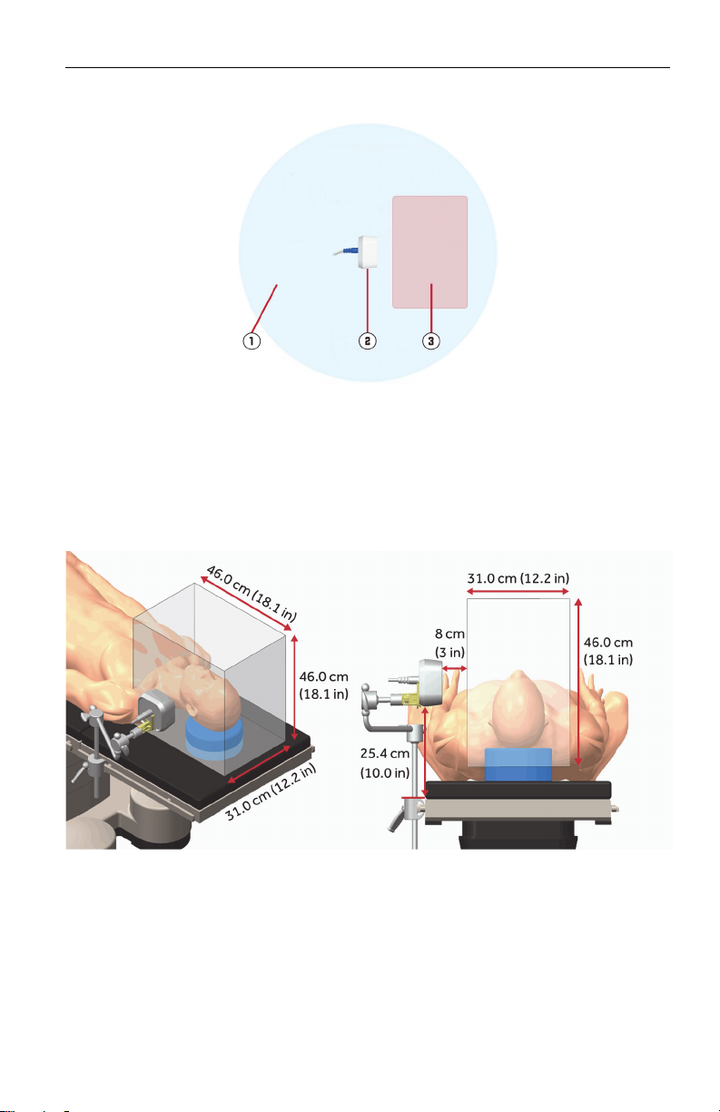
Side-mount emitter navigation field
The side-mount emitter produces a low-energy magnetic field that encompasses the
emitter. Minimize the amount of metal placed in this field. The navigation field, the
portion of the magnetic field that is appropriate for navigation, begins 8 cm (3 in)
from the emitter face and has a cubical volume of approximately 31.0 cm x 46.0 cm
x 46.0 cm (12.2 in x 18.1 in x 18.1 in) (length x width x height). For best results,
place the patient in the center of the navigation field.
2 9735730 G02 Rev. A
Emitter Quick Reference Guide
Low-energy magnetic field: Minimize the amount of metal in this field. Metal objects
such as instrument stands, equipment carts, surgical lights, and viewing screens in
1
this area will reduce the navigation field size.
Side-mount emitter
2
Navigation field
3
Note: This navigation field size is based on testing with a fluoroscopically
radiolucent surgical table with non-magnetic metal rails 3 cm to 6 cm tall by 1
cm to 3 cm wide (1.2 in to 2.4 in tall by 0.4 in to 1.2 in wide) and a 25 cm (10 in)
separation between the metal rails and the side-mount emitter.
9735730 G02 Rev. A 3
Emitter Quick Reference Guide
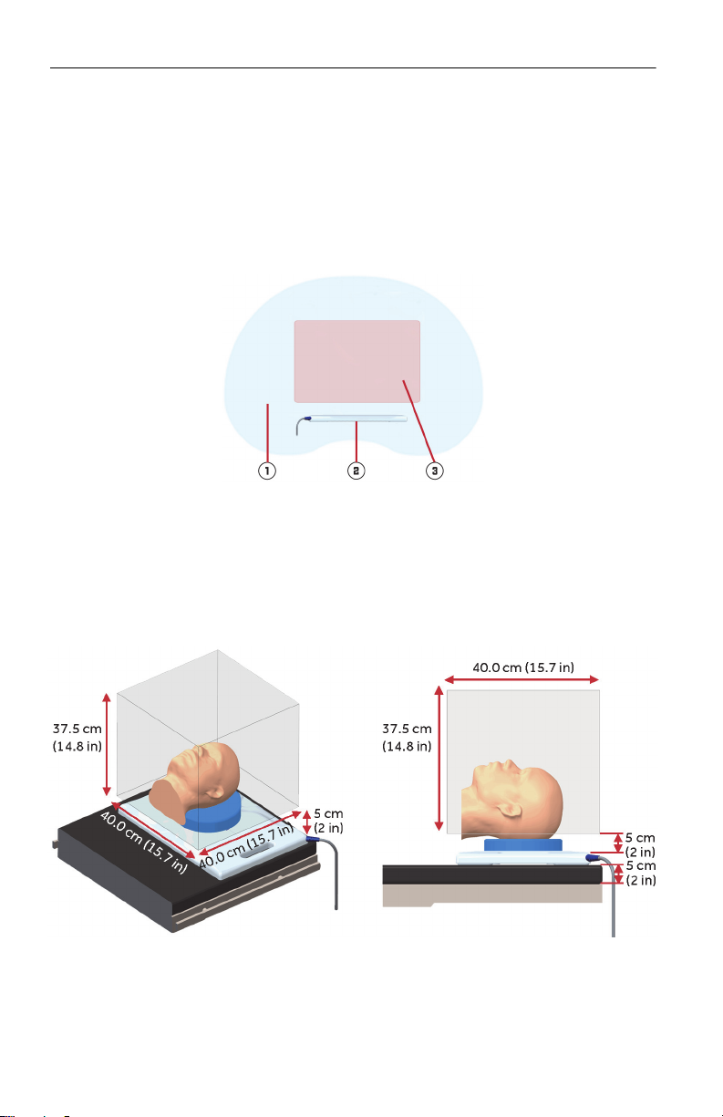
Flat emitter navigation field
The flat emitter produces a low-energy magnetic field that encompasses the emitter.
Minimize the amount of metal placed in this field. The navigation field, the portion of
the magnetic field that is appropriate for navigation, begins 5 cm (2 in) from the
emitter face and extends approximately 40.0 cm x 40.0 cm x 37.5 cm (15.7 in x
15.7 in x 14.8 in) (length x width x height). For best results, place the patient in the
bottom center of the navigation field.
Low-energy magnetic field: Minimize the amount of metal in this field. Metal
objects such as instrument stands, equipment carts, surgical lights, and viewing
1
screens in this area will reduce the navigation field size.
Flat emitter
2
Navigation field
3
Note: This navigation field size is based on testing with a fluoroscopically
radiolucent surgical table with non-magnetic metal rails 3 cm to 6 cm tall by 1
cm to 3 cm wide (1.2 in to 2.4 in tall by 0.4 in to 1.2 in wide) and a 5 cm (2 in)
separation between the metal rails and the flat emitter.
4 9735730 G02 Rev. A
Emitter Quick Reference Guide
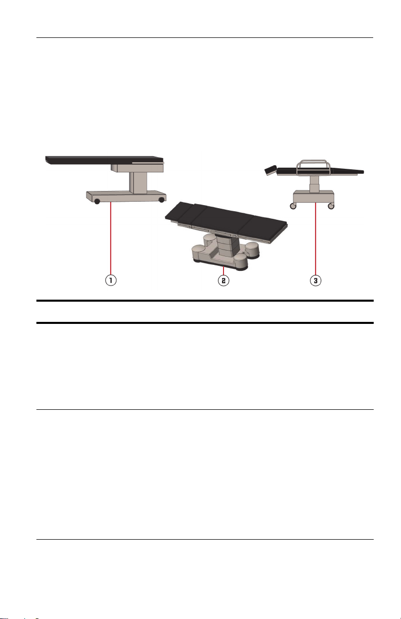
Surgical tables and emitter selection
Refer to the following table for information about using the flat emitter or side-mount
emitter with different types of surgical tables. Before surgery, try the emitter setup
with the surgical table to be used, and make sure that the software can track the
instrument and the patient reference frame throughout the range of locations
required for registration and navigation. Refer to “Refining emitter position” on page
15 for more information.
Type of surgical
table
1
Fully radiolucent
2
Fluoroscopically
radiolucent
Recommended
emitter
Flat emitter or
side-mount emitter
Flat emitter or
side-mount emitter
Details
Fully radiolucent tables do not have any metal
around the patient head and torso.
Using a fully radiolucent surgical table instead of
a fluoroscopically radiolucent table will
significantly extend the navigation field above
the flat emitter and will slightly extend the
navigation field in front of the side-mount
emitter.
Fluoroscopically radiolucent tables do not have
any metal directly under the patient head and
torso.
When using the flat emitter, a separation greater
than 5 cm (2 in) between the emitter and the
metal rails on the table will significantly extend
the navigation volume above the flat emitter.
When using the side-mount emitter, a separation
greater than 25 cm (10 in) between the emitter
and the metal rails on the table will slightly
extend the navigation volume in front of the sidemount emitter.
9735730 G02 Rev. A 5

Emitter Quick Reference Guide
Type of surgical
table
3
Non-radiolucent
Recommended
emitter
Side-mount emitter
(variable outcomes)
Details
Non-radiolucent tables and ENT chairs have
variable outcomes with EM navigation. The flat
emitter is not recommended for use with nonradiolucent tables and ENT chairs. Use of the
side-mount emitter may be possible. Position
the side-mount emitter away from metal in the
surgical tables and chairs for best results.
Setting up the side-mount emitter
Connect the side-mount emitter cable to the emitter port on the main
cart localization I/O panel.
Warning: Do not place the side-mount emitter in contact with the
patient because the emitter temperature may reach 48°C (118°F).
Caution: Visually inspect all accessory devices before use. Do not use accessory
devices if they are visibly damaged.
Caution: Procedures performed with the side-mount emitter require a surgical bed
featuring side rails because the arm assembly that supports the emitter
connects to the side rails.
Cranial procedures
Set up the side-mount emitter where it will not interfere with the surgeon’s access to
the patient during surgery.
1. Secure the Short Bedrail Adapter (9732566) to the rail of the surgical table.
Note: If the surgeon is right-handed, set up the emitter on the left-hand side.
For a left-handed surgeon, set it up on the right-hand side.
6 9735730 G02 Rev. A
 Loading...