


Nerve Integrity Monitor
NIM-Response® 3.0 and NIM-Neuro® 3.0
1. Select Procedure
1. Select Procedure
Neuro/Otology
Neuro/Otology
Custom Procedures
Custom Procedures
* indicates default settings have been changed
* indicates default settings have been changed
Monitoring
Setup
Monitoring
Setup
Step 1 of 2
Step 1 of 2
Head/Neck
Head/Neck
Peripheral
Peripheral
5/1/2009 9:00 AM
5/1/2009 9:00 AM
NIM-Response 3.0
Information
Information
®
Reports
Reports
NIM-Response® 3.0
NIM-Response® 3.0
NIM-Response® 3.0
GUI vxxxx.x.xxxxx DSP vxxx.x.xx.xxxx
NIM-Response 3.0
Global
Global
Settings
Settings
?
?
Help
Help
1. Select Procedure
1. Select Procedure
Setup
Setup
Step 1 of 2
Step 1 of 2
Neuro/Otology
Neuro/Otology
Head/Neck
Head/Neck
Peripheral
Peripheral
Custom Procedures
Custom Procedures
Monitoring
Monitoring
Information
Information
Reports
Reports
NIM-Neuro® 3.0
NIM-Neuro® 3.0
NIM-Neuro® 3.0
User’s Guide
* indicates default settings have been changed
* indicates default settings have been changed
5/1/2009 9:00 AM
5/1/2009 9:00 AM
®
NIM-Neuro 3.0
NIM-Neuro 3.0
Global
Global
Settings
Settings
GUI vxxxx.x.xxxxx DSP vxxx.x.xx.xxxx
?
?
Help
Help

NIM-Neuro 3.0 and NIM-Response 3.0
The following are trademarks or registered trademarks of Medtronic, Inc. in the United States and other countries: NIM-Response® 3.0, NIM-Neuro® 3.0, and APS®. All other trademarks, service marks, registered
trademarks, or registered service marks are the property of their respective owners in the United States and other countries.
2
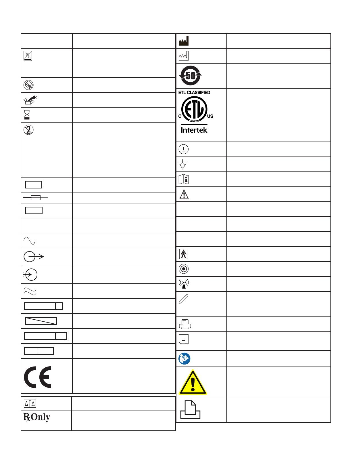
Symbols
SN
LOT
ACC
REF
STERILE R
STERILE
STERILE EO
EC REP
0123
IPX1
IPX7
IPX8
NIM-Neuro 3.0 and NIM-Response 3.0
Serial Number
Do not dispose of this product in the unsorted
municipal waste stream. Dispose of this product according to local regulations. See http://
recycling.medtronic.com for instructions on
proper disposal of this product.
Do Not Use If Package Is Open Or Damaged.
Package Contents
Use By Date
Precaution
If the single use symbol is on the device label
then this device is designed for single patient
use only. Do not reuse, reprocess, or resterilize
this product. Reuse, reprocessing, or resterilization may compromise the structural integrity
of the device and/or create a risk of contamination of the device, which could result in patient
injury, illness, or death.
Lot Number
Fuse
Accessory
Manufacturer
Date Of Manufacture
ROHS - Environmental Friendly Use Period China (SJ/T11364-2006).
Conforms To IEC/EN60601-1 and ANSI/AAMI
ES60601-1 Certied To CSA C22.2 No.60601-1
105345
Protective Earth
Equipotential
Consult Instructions for Use
Caution
Protected Against Vertical Water Drops.
Catalog Number
AC Power
Output
Input
Is Approximately Equal To
Sterilized By Radiation. Do Not Use If Package
Is Open Or Damaged.
Non-Sterile
Sterilized By Ethylene Oxide. Do Not Use If
Package Is Open Or Damaged.
Authorized Representative In e European
Community.
is Device Complies With Medical Device
Directive 93/42/EEC
Protected Against e Eects Of Temporary
Immersion In Water.
Rated For Water Ingress (IEC 60529)
Type BF Applied Part
Manual Start/Stop
Rf Transmitter (Interference May Occur).
Snapshot Option - Open Comments and Event
Title Dialog Box.
Snapshot Option - Send Snapshot or Report to
Printer and Indicates a Printer is connected.
Snapshot Option - Send Snapshot or Report to
USB Storage Device and Indicates a USB Storage Device is connected.
Follow instructions for use.
General warning sign
Quantity
Caution: Federal Law (U.S.A.) Restricts is
Device To Sale By Or On e Order Of A
Physician.
Printer
3

NIM-Neuro 3.0 and NIM-Response 3.0
Contents
Symbols ........................................................................................................... 3
Buttons and Indicators .............................................................................. 5
Glossary (used in this manual) ................................................................. 6
Indications for Use ....................................................................................... 7
Device Description .......................................................................................7
Contraindications ......................................................................................... 7
Warnings and Precautions ........................................................................7
Warnings ...................................................................................................................7
Precautions ..............................................................................................................8
NIM Quick Monitoring Setup ................................................................... 8
Basics of What You Will See and Hear During Monitoring ............. 9
When the System Arrives...........................................................................10
Unpacking and Inspection ...........................................................................10
Software..............................................................................................................10
Components ..................................................................................................10
Console Front ..........................................................................................................10
Console Left side ....................................................................................................10
Console Rear ............................................................................................................10
Patient Interface .....................................................................................................11
Patient Simulator ...................................................................................................11
Stimulator Probes/Handles ................................................................................11
Monopolar .........................................................................................................11
Bipolar .................................................................................................................12
Muting Detector .....................................................................................................12
APS Electrode Handswitch .................................................................................12
Electrodes .................................................................................................................13
Power Cords .............................................................................................................13
The Splash Screen ..................................................................................................14
Self Test ...............................................................................................................14
Setup Mode .................................................................................................... 14
Select Procedure Step 1 of 2 Screen .........................................................14
Global Settings .......................................................................................................15
Add/Maintain Custom Titles and Comments on the Global
Settings Screen ................................................................................................15
Quick Tags ..........................................................................................................16
Help ..............................................................................................................................16
View Electrode Placement Using the Help Screen ..............................16
Electrode Placement ......................................................................................17
Listen to Audio Samples ...............................................................................18
Place Electrodes Step 2 of 2 Screen .................................................................18
Electrode Check ......................................................................................................18
Electrode Check Panel ...................................................................................18
Electrode check Panel Pass/Fail ..................................................................18
Electrode Check Show Details Panel ........................................................20
Electrode Type Panel ......................................................................................20
Case Information ....................................................................................................20
Procedure Settings Panel ....................................................................................21
Advanced Settings ................................................................................................22
Audio Tab ...........................................................................................................22
Monitoring Tab .................................................................................................23
Identify STIM1 and STIM2 Names ..............................................................24
Stimulus Artifact Example ............................................................................ 24
Special Note on Recognizing Artifact ...................................................... 25
Important Note on Stimulator Adjustments .........................................25
Microscope Tab (available on the NIM-Neuro 3.0 only) ....................26
APS Tab ................................................................................................................27
Monitoring Mode ......................................................................................... 28
Events Panel .............................................................................................................29
Control Panel ...........................................................................................................29
The APS Monitoring Screen ...............................................................................30
Mute an APS Alarm .........................................................................................31
The Reports Mode ........................................................................................ 32
Select Report Format ............................................................................................32
Snapshots/Event Reports .............................................................................32
Choose Report Content .......................................................................................33
Generate Snapshots/Events Report Format.................................................33
Snapshots/Events Reports .pdf Image Example .................................34
Select the Log File ..................................................................................................34
Construct the Log File ..........................................................................................34
Generate the Log File ...........................................................................................35
Log Reports pdf Image Example ............................................................... 35
Log Reports .csv (in Excel) Example ..........................................................35
APS Reports .............................................................................................................33
APS Reports .pdf Image Example .............................................................. 36
Creating a Report ...................................................................................................36
Snapshots Report ............................................................................................ 36
Log Files .....................................................................................................................37
Quick Reports .......................................................................................................... 37
Special Functions and Features ...............................................................37
Visual Alarms and Warnings ...............................................................................37
Audio – Understanding What You Hear .........................................................38
Alarms ..................................................................................................................38
Voices ...................................................................................................................38
Tones ...................................................................................................................39
STIM Bur Guard ................................................................................................39
System Set-Up ............................................................................................... 39
Operating Room Set-Up ......................................................................................39
Typical Set-Up (shown with IPC) ................................................................39
Anesthesia Requirements ............................................................................39
Muting Detector Set-Up ......................................................................................40
Muting .................................................................................................................41
Monopolar Electrosurgical Instrument Clamping ...............................41
Patient Interface Set-Up .............................................................................41
Patient Interface and Stimulators ...................................................................41
Monopolar Incrementing Probe ................................................................42
Monopolar Probe with Universal Handle ...............................................42
Bipolar Probe ....................................................................................................43
APS Electrode Stimulator .............................................................................43
Patient Interface and Stimulator Combinations .........................................43
Monopolar Incrementing Stimulator and APS
Electrode Stimulator ......................................................................................44
Monopolar Probe and Stimulus Dissection Probe ..............................44
Bipolar and Monopolar Probe ...................................................................44
Monitor Set-Up ..............................................................................................45
Basic Set-Up All Procedures ...............................................................................45
Standard Set-Up .....................................................................................................45
Custom Set-Up ........................................................................................................45
Additional Settings................................................................................................46
For Installing the Stimulating Electrode .................................................46
APS Monitoring ......................................................................................................46
Changing APS Settings .................................................................................47
Surgery Notes ...................................................................................................47
After Surgery ...........................................................................................................47
When the Case is Complete ...............................................................................47
When Monitoring is Complete ..........................................................................47
Power Disconnection .....................................................................................47
Cleaning and Maintenance .......................................................................47
Cleaning (after each use) .............................................................................47
Storage ................................................................................................................47
Maintenance .....................................................................................................47
Maintenance Schedule ..................................................................................48
Fuses ...........................................................................................................................49
Console Replacement ....................................................................................49
Patient Interface Replacement ...................................................................50
Troubleshooting ...........................................................................................51
Technical Specications ........................................................................... 52
Accessories / Parts List ................................................................................ 55
System Components & Accessories ..........................................................55
Annual System Quick Check ..............................................................................56
Patient Simulator Instructions for Use .................................................. 57
Introduction .............................................................................................................57
System Description ...............................................................................................57
System Set-Up .........................................................................................................57
Simulator Set-Up .............................................................................................57
System Assessment ...............................................................................................58
Conrming Electrodes ...................................................................................58
Electrode Lead O ..........................................................................................59
Stimulation ...............................................................................................................60
Mechanical Stimulation ................................................................................60
Stimulus: Set and Measure ...........................................................................60
Threshold Test ..................................................................................................61
Cleaning ..............................................................................................................61
Storage ................................................................................................................60
Troubleshooting .............................................................................................60
The NIM 3.0 Equipment Cart .................................................................... 62
Uncrating ..................................................................................................................62
NIM 3.0 Tether .........................................................................................................62
Channel Default Settings...........................................................................63
Display Default Settings.............................................................................64
STIM1 & 2 Default Settings ...................................................................... 64
Microscope Default Settings .................................................................... 64
Guidance and Manufacturer’s Declaration –
Electromagnetic Immunity ....................................................................... 65
Part I ............................................................................................................................65
Part II ...........................................................................................................................66
Limited Warranty .......................................................................................... 67
4
NIM-Neuro 3.0 and NIM-Response 3.0
Ω
Ω
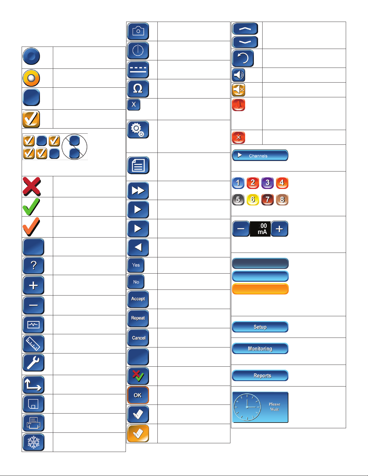
Buttons and Indicators
In this section all buttons used on the “Touch
Screen User Interface” are displayed with an
explanation of how they work.
Radio Button / Deselected: For
option selection where choice
is limited to one of two or more
options.
Radio Button / Selected
Check Box: Deselected For
option selection where choice is
to enable or disable a single or
multiple options.
Check Box: Selected
EMG Audio and Event Tones Check Boxes:
One or both must be selected. Both cannot be
deselected.
Red X: Indicates a failed test.
Snapshot Button: Saves current
screen to memory or to selected
peripheral device.
Activate Button: Activates
STIM2 stimulus adjustment
buttons.
Baseline Button: Initiates an APS
baseline acquisition sequence
Electrode Check Button: Opens
Electrode Status Panel
Delete/Close Button: Closes
“Delete Procedure” dialog box
Opens “Delete a Custom Procedure” dialog box
Global Settings Button: Global
Settings allows the user to select
screen language, date/time format and the Diagnostic Mode, as
well as set system date/time and
Restore Factory Defaults
Information Button: Opens
Information Screen to enter:
Surgeon’s Name
Patient’s Name
Notes
Fast Rate Button: Selects APS
Pulse Fast Rate
Scroll Up/Down Buttons: Used to
scroll through selected events
Restore Button: Used to restore factory defaults.
Mute Button: Used to mute channel.
Unmute Button: Used to unmute
channel.
APS Visual Alarm Indicator and
Mute Button Automatic On/O Indicator Button. Only displayed when
an APS alarm limit has been reached
and APS alarm tone sounds. Also
used to mute APS alarm.
APS Alarm Button - Used to un-mute
APS alarm
Channels Button: Opens a drop-down menu used to
name channels.
Green Check: Indicates a successfully passed test.
Orange Check: Indicates an Active Channel.
Select Button: Option Button
See associated text indicating
option.
Help Button: Opens Help Screen
for Electrode Placement &
Sound Samples
Increase Button: Increases value/
Setting
Decrease Button: Decreases
value/Setting
Monitor Button: Opens Monitoring Screen
Measure Button: To view details
of the event waveform.
Advanced Settings Button
Opens: Audio, Monitoring,
Stimulation, Microscope, and
APS Panels.
Display Button: Opens panel for
adjusting amplitude and time
scales.
Save Button: Sends selected
information to USB mass storage device.
Print Button: Used in Reports
Section to print reports
Freeze Button: Freezes entire
screen (all channels)
Normal Rate Button: Selects
APS Pulse Normal Rate
Next Button: Opens the next
screen or graphic display
Previous Button - Opens the
previous screen or graphic
display
Yes Button: Accept/Keep
No Button: Do not Accept/Keep
Accept Button: Function as
indicated.
Repeat Button: Function as
indicated.
Cancel Button: Function as
indicated.
Show Details Button: Used to
show impedance readings
Hide Details Button: Used to
hide impedance readings
OK Button: Used to close panels
Select All Button- Used to select
all events in memory
Deselect All Button: Used to
deselect all events in memory
Channel Buttons Channels can be turned On, O
or Muted
Decrease/Increase Buttons and Setting Display
Used to make adjustments to the subject as dened
in the open panel.
Setup
Setup
Setup
Setup
Setup
Setup
Multi State Buttons (Set-Up used as an example):
Gray = Inactive (not selectable)
Blue = Selectable
Orange = Selected
Setup Button: Opens/Starts the setup process
Monitoring Button: Opens the Main/Monitoring
Screen
Reports Button: Opens the Reports Screen
Program Loading Indicator
5

NIM-Neuro 3.0 and NIM-Response 3.0
Glossary
APS Automatic Periodic Stimulation.
DSP Digital Signal Processor.
Event Sequence A series of events separated from each other by less than one second.
FCU Foot Control Unit.
GUI Graphical User Interface.
NIM Nerve Integrity Monitor.
NIM 3.0 NIM-Neuro 3.0 or the NIM-Response 3.0
Stimulus Artifact A monitoring term for an artifact created by stimulus voltage delivered to the patient, which is
picked up as feedback either internally or externally to the monitoring equipment. It is normally
small and does not impact monitoring but can, under certain conditions, be displayed and sounded
on the monitor.
Stimulus Artifact On-Screen On the monitoring screen, the stimulus artifact appears as an event (above or below threshold)
which starts directly after the stimulus on the left side of the screen and proceeds for a duration into
the EMG waveform detection area. The level of the artifact is directly proportional to the stimulus
delivery and cannot be EMG because nerve signals need time propagate.
Stimulus Artifact Sound The audio representation of a stimulus artifact. It is a high frequency sound similar to a cymbal (ti--
tchi). This sound should not be confused with an EMG sound which sounds like a drum beat.
Stimulus Rejection
Period
Adjustable delay reading EMG after stimulation. In previous versions of the NIM, this was referred to
as Stimulus Artifact or Artifact Delay.
6

NIM-Neuro 3.0 and NIM-Response 3.0
Indications for Use
The NIM 3.0 is intended for locating and identifying cranial and peripheral motor and mixed motor-sensory nerves during surgery, including
spinal cord and spinal nerve roots. The APS™electrode is an accessory intended for providing automatic periodic stimulation to nerves when
used with the Medtronic Nerve Monitoring Systems.
Indications for NIM 3.0 EMG Monitoring Procedures include:
Intracranial, Extracranial, Intratemporal, Extratemporal, Neck Dissections, Thoracic Surgeries, and Upper and Lower Extremities
Indications for Spinal procedures which may use NIM 3.0 EMG monitoring include:
Degenerative Treatments, Pedicle Screw Procedures, Fusion Cages, Rhizotomy, Orthopedic Surgery, Open and Percutaneous Lumbar and Cervical
Surgical Procedures, and Thoracic Surgical Procedures.
Device Description
The NIM-Neuro 3.0 is an eight-channel and the NIM-Response 3.0 is a four-channel EMG monitor for intraoperative use during surgeries in which
a nerve is at risk due to unintentional manipulation. The NIM 3.0 System records electromyographic (EMG) activity from muscles innervated
by the aected nerve. The monitor will assist early nerve identication by providing the surgeon with a tool to help locate and identify the
particular nerve at risk within the surgical eld. It will continuously monitor EMG activity from the muscles innervated by the nerve at risk to
minimize trauma by alerting the surgeon when a particular nerve has been activated. The monitor utilizes touch screen and color graphic user
interface (GUI) along with the audio feedback to increase the usability of the device.
Contraindications
The NIM 3.0 is contraindicated for use with paralyzing anesthetic agents that will signicantly reduce, if not completely eliminate, EMG responses
to direct or passive nerve stimulation.
Warnings and Precautions
It is important that the NIM-Neuro 3.0 and NIM- Response 3.0 intended operators be familiar with this manual: its Warnings, Precautions, procedures and safety issues. Disregarding the information on safety is considered abnormal use.
Warnings
W1 The NIM does not prevent the surgical severing of nerves. If monitoring is compromised, the surgical practitioner must rely on alternate
methods, or surgical skills, experience, and anatomical knowledge to prevent damage to nerves.
W2 If paralyzing anesthetic agents have been used, patient must regain muscle activity prior to use of the NIM-Neuro/Response 3.0 EMG
Monitor.
a. To limit the paralytic eect of anesthetic agents, the anesthesiologist should monitor Train-of-Four (TOF) to prevent diminished EMG
activity. Consult anesthesiologist if EMG changes are observed.
W3 Surgical Identication of exposed Neural structures is key to their preservation. Failure to use Nerve Stimulation Probe may contribute to
unintended surgical nerve damage or resection.
W4 To avoid the risk of re or explosion, do not use the Medtronic NIM System in the presence of ammable anesthetics and/or oxygen rich
environment.
W5 After each procedure, properly clean and disinfect all reusable system components.
W6 To avoid alternate site patient burns or lesions:
a. Do not activate the electrosurgical instruments (ESU) while stimulator is in contact with tissue.
b. Do not leave dissection instruments, stimulating electrodes, or probes in surgical eld.
c. Do not store dissection instruments, stimulating electrodes, or probes in electrosurgical instrument holder.
d. Do not allow a second surgeon (for example, fat harvesting) to use electrosurgical instruments while stimulator is in use.
e. Do not activate electrosurgical instrument for prolonged periods while ESU is not in contact with tissue.
f. Do not activate electrosurgical instrument near the recording or stimulating electrodes.
g. Do not allow patient interface boxes or recording / stimulating electrodes sites to be ooded with saline.
h. Do not allow excessive stray AC or DC leakage currents from patient connected equipment; Avoid creating an unintended grounding
path through applied electrodes.
Practitioner is responsible for proper use, periodic safety certication of patient connected equipment, and AC power grounding in
accordance to the appropriate IEC 60601-1 and/or IEC 60601-1-1 medical safety standard.
W7 Disconnect power to the console before cleaning the unit to avoid electrical macro shock.
W8 Achieve electrical grounding reliability with proper connections. Connect the console to hospital grade receptacles only.
W9 DO NOT use any parts other than Medtronic Xomed, Inc. components as damage or substandard performance could result.
W10 This medical device complies with IEC/EN60601-1-2 safety standard for electromagnetic compatibility, requirements and test. However,
if this equipment is operated in the presence of high levels of electromagnetic interference (EMI) or highly sensitive equipment,
interference may be encountered and the user should take whatever steps are necessary to eliminate or reduce the source of the
interference. Diminished performance may lengthen operating time for anesthetized patient.
W11 It is important that the NIM-Neuro/Response 3.0 operator be familiar with this manual, its precautions, procedures and safety issues.
W12 To avoid electrical shock, do not attach unapproved components or accessories to the Medtronic NIM System.
W13 All service must be performed by Medtronic qualied personnel only.
W14 Do not directly contact active, implanted devices with the stimulator as it may disrupt the implanted device’s operation. Consult medical
specialist before use.
W15 Electrocardiogram monitoring artifacts may be caused by Medtronic NIM stimulus current delivery or EMG electrode impedance
monitoring.
7

NIM-Neuro 3.0 and NIM-Response 3.0
W16 Use of unapproved stimulators, stimulus probes, stimulus dissection instruments or electrodes may result in compromised Medtronic NIM
operation, such as, but not limited to decreased accuracy.
W17 Repair and/or modication to the Medtronic NIM or any accessory by anyone other than qualied service personnel may signicantly
compromise the unit’s ability to monitor nerve activity and/or void the equipment warranty.
W18 To avoid the risk of infection, the user must maintain good sterility practices.
W19 False negative responses (failure to locate nerve) may result from:
a. Shorted EMG electrode or cabling (conductive parts of applied needle electrodes or cables contacting each other).
b. Patient Interface fuse blown and not detected (32mA, 250V. Xomed Part No.: 8253075).
c. Patient Interface defective.
d. Inadequate stimulus current.
e. Inadequate current for stimulation of nerve through hardware, such as stimulus dissection instruments, may vary based on the physical
size, shape characteristics, and design of the hardware and proximity to the nerve.
f. Simultaneous stimulation of the nerve and the surrounding tissue, resulting in current shunting (inadequate delivery of stimulus
current to target nerve tissue).
g. Flatline on the EMG channel caused by shorted internal amplier (characterized by baseline activity of < 3μV peak-to-peak).
h. EMG electrodes not positioned properly in the target muscles.
W20 Stimulator current may cause involuntary patient movement resulting in patient injury.
W21 If the incrementing probe handle malfunctions, it could result in increased current delivery to the patient. Immediately disconnect the
Control Plug from the Patient Interface box and use the console to adjust stimulus current.
W22 Be careful not to damage vascular or neural structures when preparing the nerve for the installation of the APS Electrode.
W23 Electrode integrity should be checked after electrode insertion and before electrode removal to give additional assurance that electrode
continuity was maintained throughout the entire procedure. If the system indicates improper electrode impedance, consult the
Troubleshooting topic for impedance value troubleshooting.
W24 Remove APS electrode from patient prior to using external debrillator to prevent thermal injury to patient at APS electrode site.
W25 Operation in close proximity to high frequency (shortwave or microwave) equipment may produce instability in the electrical stimulator
output.
W26 Safe stimulus levels are dependent on various conditions including but not limited to: type of excitable tissue, Charge Per Pulse, and
Charge Per Unit Area. Waveform morphology, repetition rate, and stimulator eective surface area must be considered. Special operator
(Neurophysiologist) attention is required for stimulus levels which exceed default settings or conditions. Levels higher than 2mA RMS/
cm2 (3 mA) for Slim Prass Probe and Prass Bipolar Probe may result in tissue damage.
W27 Do not perform Magnetic Resonance Imaging (MRI) on a patient with electrodes, probes, and EMG tubes in the eld. The eect of MRI is
unknown on these devices.
W28 Loud extraneous monitoring noise may be caused by activation of electrosurgical unit. Muting Detector must be properly attached to the
active electrosurgical lead.
Precautions
P1 Medical Electrical Equipment needs special precautions regarding electromagnetic compatibility (EMC) and needs to be installed and put
into service according to the EMC information provided in this Guide.
P2 Portable and mobile RF including cell phones and communications equipment can aect Medical Electrical Equipment.
P3 Use of accessories and cables other than those specied and sold by Medtronic may result in increased emissions and decreased
immunity of this unit.
P4 The NIM-Neuro/Response 3.0 should not be used adjacent to or stacked with other equipment. If adjacent or stacked use is necessary, the
NIM-Neuro/Response 3.0 should be observed to verify normal operation in the conguration in which it will be used.
P5 Inability to deliver stimulus current ow may be caused by inadvertent simultaneous current delivery from both STIMprobe outputs,
resulting in current shunting.
P6 Avoid accidental contact between ‘PATIENT APPLIED PARTS’ and other conductive parts including those connected to protective earth.
P7 The metal Muting Probe (Ref - 8220325) is compatible with previous versions of the NIM. However, previous versions of the Muting Probe
are NOT compatible with the NIM 3.0 System.
P8 The muting detector is susceptible to damage from dropping. Visually inspect inner jaw surfaces for cracking, chipping or damage prior
to use. Insucient muting may result.
NIM Quick Monitoring Set-Up
The following procedure for OR sta users is not meant to replace a complete understanding of this user’s guide, but may serve as a quick
reminder of basic NIM setup, monitoring screens, and monitoring sounds. Refer to the Monitoring set-up topic for more information.
1. Place the NIM 3.0 system within the surgeon’s view and plug the NIM power cord into the dedicated outlet.
2. Turn the NIM system on. The self-test is complete.
Note: Do not use long-term paralyzing anesthetics to ensure proper EMG monitoring.
3. On the NIM SET-UP screen, select a specic surgery to be monitored. The Place Electrodes illustration appears indicating how to make the
connections.
4. Synchronize the NIM date and time to the OR clock, enter the patient information, and surgeon name.
5. Following the illustration on the screen, connect all color coded cables (subdermal electrodes or EMG tube, ground, and STIM 1 return) to the
corresponding patient interface.
8
NIM-Neuro 3.0 and NIM-Response 3.0
6. Connect a monopolar stimulator probe to the STIM 1 jack. Note: Once the electrodes are connected, the Automatic Electrode Check: GREEN
Checks conrms the integrity of the connections.
7. Clip the muting detector to the monopolar electrocautery cord(s) and plug it into the MUTE input located on the back of the NIM console.
8. Begin monitoring by proceeding to the Monitoring panel by pressing Monitor. Your NIM 3.0 system is ready to monitor with its default
settings.
Basics of What You Will See and Hear During Monitoring
The following procedure is meant to be completed by surgeons and OR sta users. Refer to the Monitoring Mode topic for more information.
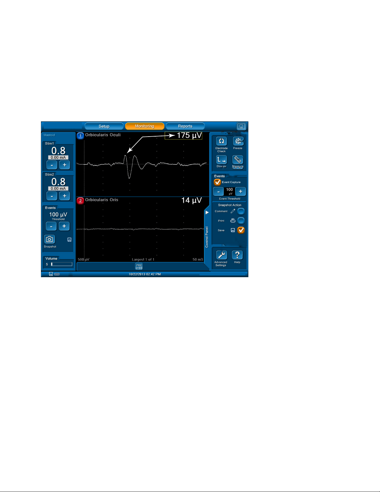
1. The surgeon stimulates the nerve with a probe to conrm the location and integrity of the nerves.
Upon stimulation of the nerve, EMG is evoked and is audible in the form of event tones and raw EMG sounds pulsed at ~4X/sec. The EMG
event is also shown on the monitoring screen as a waveform. See gure 1.
Figure 1. Biphasic EMG waveform
• Peak-to-peak measurement or amplitude.
• Note the latency is measured from the stimulus from the left hand side of the screen to the start of the EMG waveform.
2. The surgeon uses the stimulator probe as the primary means to conrm the location and integrity of the nerves.
The NIM is continuously monitoring and you may also hear changes in the EMG, or mechanically evoked nerve responses that look and sound
similar to stimulator evoked nerve responses.
Note: It is important to understand the NIM system’s visual and audio feedback so as not to confuse the stimulus artifact with real EMG, or
recognize if both the stimulus artifact and real EMG are present at the same time.
The NIM system sounds a “Current Delivery” tone (a short warble sound) when contacting tissue, but not evoking a response. The tone
indicates the set current is being delivered.
3. The surgeon conrms the integrity of the nerve using the probe throughout the entire procedure including at the end.
4. If desired, document the pre- and post-surgical EMG monitoring responses with the Reports or Save features on the NIM.
Refer to the table of contents for more information on the following related topics:
• Stimulus artifact
• Threshold
• Undertanding audio/visual
9

NIM-Neuro 3.0 and NIM-Response 3.0
When the System Arrives
Unpacking and Inspection
Check o the contents of the box against packing slip. If incomplete or damaged, notify Customer Care.
If container is damaged, or cushioning material shows stress, notify carrier and Customer Care. Keep shipping materials for carrier inspection.
After unpacking, save the cartons and packing material. If the instrument is to be shipped the shipping package will provide proper protection.
Software
Software information (manufacturer, version, and release date) is contained on a card packaged with the system. Save this card for future
reference.
Components
Console Front
1 - STIM1 stimulus adjustment.
2 - STIM2 stimulus adjustment.
3 - Touchscreen. The Touch Screen displays EMG waveforms and controls many of the functions of the
NIM 3.0.
4 - Volume adjustment.
5 - Product name.
6 - The Speaker provides audio alarms, acoustic EMG monitoring, and voice prompts.
Console Left side
1 - Anti-Glare Stand. Use this device to change the viewing angle of the NIM 3.0 screen. It is shown in
the tilted (up) position.
2 - USB Out. The USB Out is an industry standard USB type connector that you can use with mass
storage devices.
1
2
3
4
5
6
2
Console Rear
1 - Carry Handle for transporting unit.
2 - Potential equalization terminal. Can be used to equalize ground potentials between O.R.
instruments.
3 - Accessory Power Outlet. Use this power outlet with the NIM 3.0 printer power device only.
4 - Fuse Access. The AC power fuses are located on the back of the units.
5 - Power Switch. The power switch turns power on or o.
6 - Power Connector. The power cord plugs into the back of the NIM 3.0 System console. The input
fuses and accessory output is in the power entry module. Plug the power cord into the A/C
power outlet.
7 - Anti-Glare Stand. Use this device to change the viewing angle of the NIM 3.0 screen. It is shown
in the tilted up position.
8 - Patient Interface Connector. The patient interface connector is a 44-pin D-sub.
9 - RCA Audio Jack. An RCA audio jack is provided to output an audio signal that you can overlay
onto a video signal when using industry standard recording devices. The output is audio line
level (1 Vp-p).
10 - Handswitch connector. Used for APS procedures only.
11 - Muting Detector Input. Near-eld radio frequency detector.
12 - Mini Jack. Standard conguration used for private listening through Stereo Headphones.
13 - For future use.
14 - Surgeon Mini Screen Port. Output connection to Surgeon Mini Screen or video recorder.
15 - USB Out. The USB Out is an industry standard USB type connector (two port) that you can use
with mass storage devices/printer/keyboard.
16 - VGA Output. Only used to connect NIM-Neuro 3.0 System to microscope.
Note: Microscope VGA output not active on NIM-Response 3.0
System.
Important:
Intraoperative use of the VGA Out and RCA Phone Jack requires special considerations to remain
compliant with IEC/EN60601-1. Contact Medtronic Xomed for recommendations if intraoperative
use of the VGA Out, RCA Phone Jack.
1
1
8
2
3
4
5
6
7
10
11
12
13
14
15
16
9
10

Patient Interface
1 - Electrode ground. Signal return for patient electrodes.
2 - Stimulating Instrument Jack or Stimulator Probes (Monopolar or Bipolar).
3 - Incrementing Probe Control Jack. Connects Incrementing Probe controls
to the NIM 3.0.
4 - Stimulus (out) Jack, negative (-).
5 - Stimulus Return, positive (+).
6 - Patient Interface to console connector.
7 - Connector release.
8 - The Patient Interface fuses are for Stimulator Output and specically
tested for ECU protection.
9 - Positive Electrode Jacks. Positive electrodes have matching color-coded
wires and plugs.
10 - Negative Electrode Jacks. Negative electrodes have black wires and
color-coded plugs.
11 - Patient Interface Clips.
12 - NIM-Response 3.0 Patient Interface shown for reference only.
Note: Use Xomed 11270048 Fuse, 5 x20mm, 32mA, 250 V. Order 8253075
Fuse Kit for replacements.
NIM-Neuro 3.0 and NIM-Response 3.0
1
2
3
4
5
8
9
10
11
6
7
12
Patient Simulator
Use the Patient Simulator for troubleshooting and demonstrating the system
without the need for patient interaction.
1 - Stimulator pads (Simulated Events).
2 - Stimulator return (anode) plug.
3 - Electrode ground plug.
4 - Simulated subdermal electrode plugs.
Stimulator Probes/Handles
The Stimulator Probes and Handles carry stimulus current from the console via the Patient Interface, to the patient.
Monopolar
Ball Tip Probe
1 - Stimulus to Patient Contact Area
2 - Insulated Sleeve
3 - Probe Base
Standard Prass Flush Tip Probe
1 - Stimulus to Patient Contact Area
2 - Insulated Sleeve
3 - Probe Base
Incrementing Monopolar Probe Handle
The Incrementing Probe provides the ability to adjust the stimulus and to print or save events from within the surgical site.
1 - Toggle Button
2 - Probe Jack
3 - Stimulus Plug
4 - Toggle Button Control Plug
1
2
1
2
1
2
3
3
3
4
1
2
3
4
11

NIM-Neuro 3.0 and NIM-Response 3.0
1
5
Incrementing Probe Stimulus Adjustments
The (single use) Incrementing Probe provides the surgeon with the means to adjust the stimulation current at surgical site.
2 3
1
1 - Toggle button normal or at rest.
2 - Increase current.
3 - Decrease current.
4 - Press and hold saves current screen to memory (for Reports) and to selected peripheral device (Printer and/or USB ash drive).
Universal Monopolar Probe Handle
1 - Handle.
2 - Probe Jack.
3 - Stimulus Plug.
2
3
4
Bipolar
Side-by-Side Stimulating Probe
1 - Cable Connection.
2 - Stainless Steel Tubing.
3 - Stimulus to Patient Contact Area.
4 - Insulating Sleeve.
Prass Flush Tip Stimulating Probe
1 - Cable Connection.
2 - Stainless Steel Tubing.
3 - Stimulus to Patient Contact Area.
4 - Insulating Sleeve.
Muting Detector
Refer to Precaution P8 for more information.
The Muting Detector Probe is designed to detect the presence of
electronic noise from external devices (such as electrocautery/
electrosurgical unit) that may cause interference on the EMG monitor.
1 - Anti-slide Ring.
2 - Electronic Noise Detection Area.
3 - Insulating Sleeve.
4 - Cable Connector.
5 - Ferrite.
1
2
3
4
1
2
3
4
1
2
3
4
APS Electrode Handswitch
The APS electrode handswitch cycles through the APS functions (O,
Slow, Fast).
1 - Thumb Switch.
2 - Cable.
1
2
12
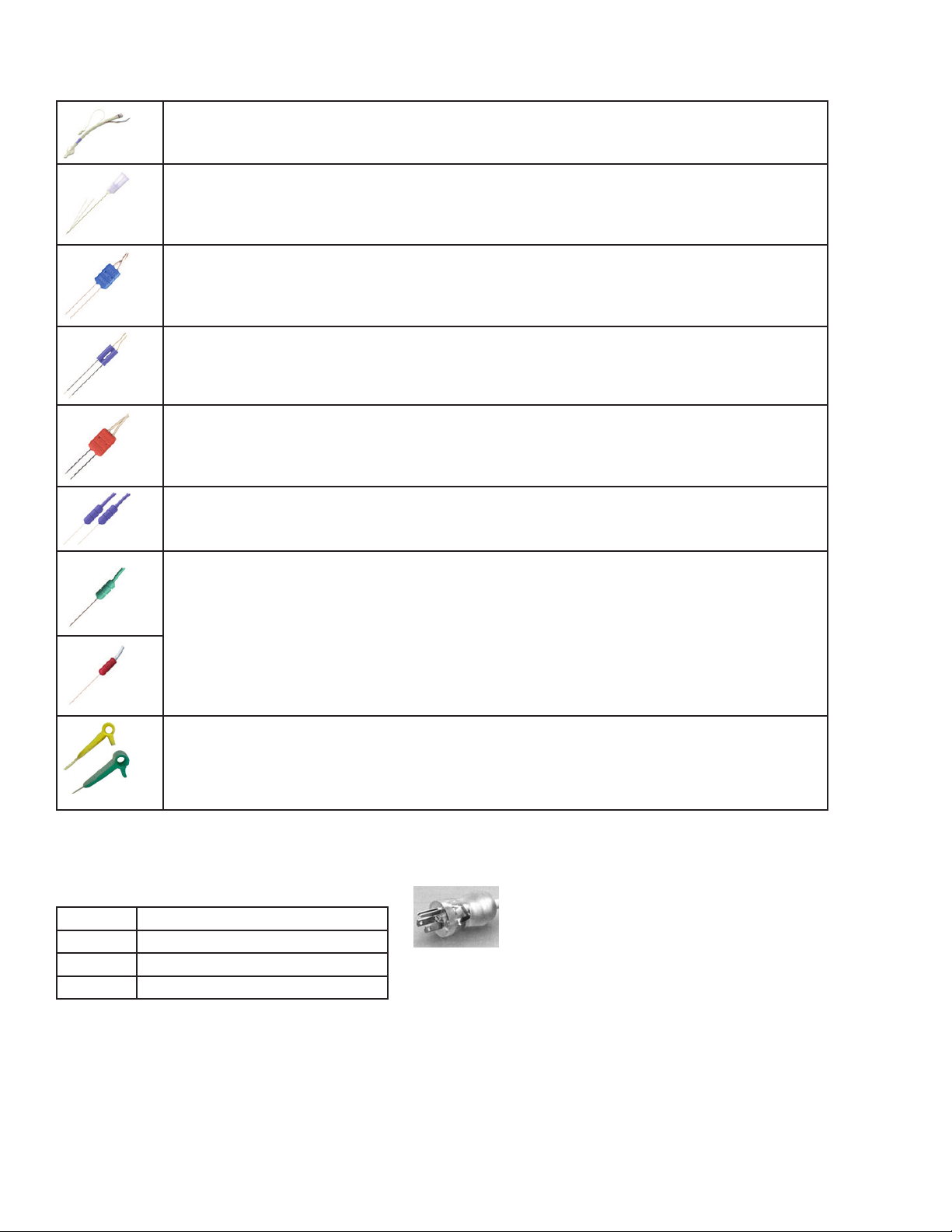
Electrodes
Electrode types recommended for use with the NIM 3.0 System
NIM EMG Endotracheal Tube. Contact electrodes designed to monitor both vocal cords.
Hookwire Electrode. Two small wires attached to the end of a hypodermic needle. Injected intramuscularly (then
the hypodermic needle is removed). The wires are insulated to within 3 mm of the end and are designed to
obtain a more specic response.
Paired Subdermal Electrodes. Non-insulated high performance electrodes with 2.5mm spacing.
Prass Paired Electrodes. The electrodes are insulated to within 5mm of the end with 5mm spacing. Musclespecic single use.
Prass Paired Electrodes Small Hub. The electrodes are insulated to within 5mm of the end with 2.5mm spacing.
Muscle-specic single use.
NIM-Neuro 3.0 and NIM-Response 3.0
Subdermal Needle Electrodes. Non-insulated high performance electrodes 12mm long with a 0.4mm diameter.
Electrode Ground (Green with Green Wire) and Electrode Stimulus Return (Red with White Wire).
APS (Automatic Periodic Stimulation) Electrode.
Continuous, real-time monitoring of vagus nerve through low-level stimulation.
Single-use.
Power Cords
1897821 Power Cord, 6 Meter, 115 V
1895820 Power Cord Standard, U.S.
1895822 Power Cord, 6 Meter, Europe, U.K.
1895823 Power Cord, Japan, 100 V
Additional information can be found at www.mcatalogs.com/ent/ .
13
NIM-Neuro 3.0 and NIM-Response 3.0
6
Splash Screen
Self Test
The system automatically performs an internal integrity check each time you turn the NIM-Response 3.0 ON. Refer to the Maintenance Schedule
topic for more information.
Once the NIM-Response 3.0 powers-up, the system briey diplays a series of messages. Then the console does a series of self-tests on the
hardware.
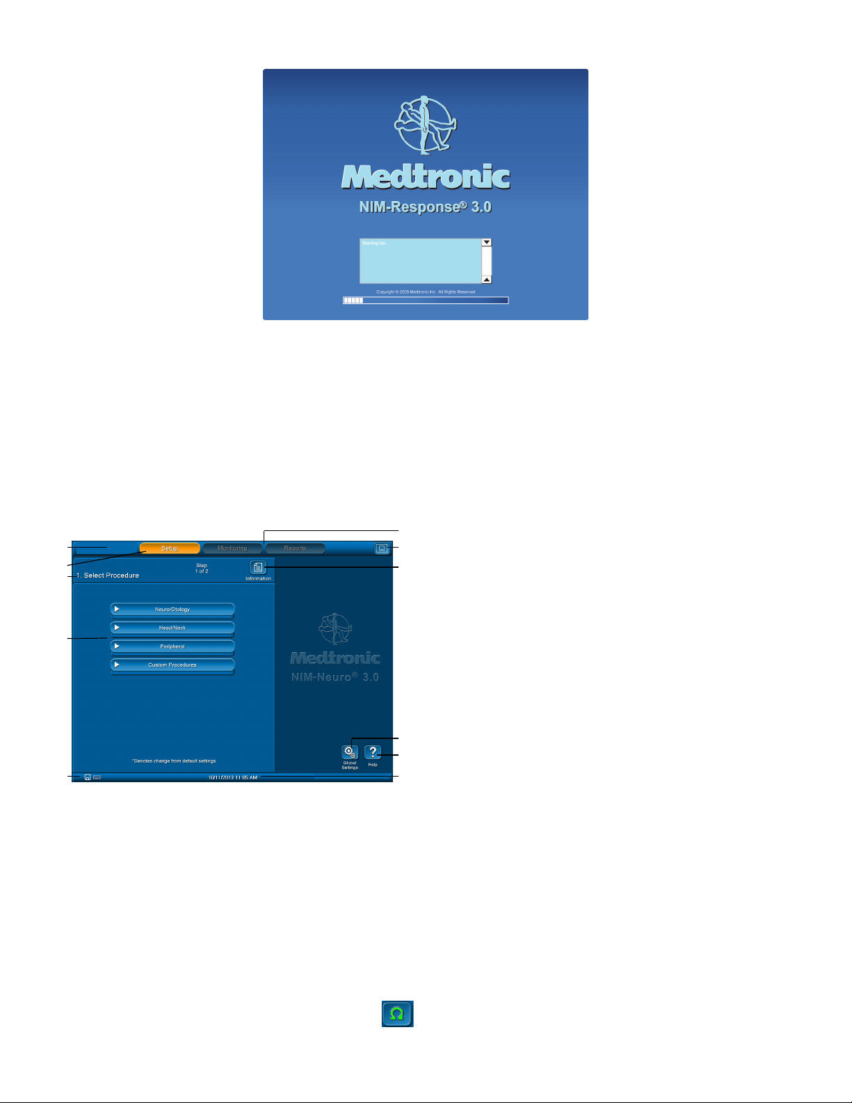
Setup Mode
Select Procedure Step 1 of 2 Screen
The Setup screen is the default screen. You must select an existing procedure or begin a new (custom) procedure from the default screen.
Optional: You may enter/change the date, time, language, or data elds via the Global Setting button.
1 Tool bar. Select any of the three major functional modes.
1
2
3
4
5
1. Select one of the following procedures by touching it on the screen.
• Neuro/Otology
• Head/Neck
• Peripheral
• Custom Procedures
The system opens a drop down menu which includes a selection of pre-dened procedures.
2. From the drop down menu, select one of the pre-dened procedures by touching it.
The Place Electrodes screen appears.
3. Place the electrodes according to the diagram.
4. Do one of the following:
• Go directly to monitoring either by pressing the Monitoring selection on the top toolbar, or by pressing Monitor.
7
2 Setup button (default)
8
3 Set up wizard navigation bar
4 Select procedure (drop down menus)
5 Print, Save, and keyboard icons. These icons only appear if you
connect a USB drive, keyboard, or printer.
6 Monitoring and report buttons. Not available on start up.
7 Screen print/Screen save button (if USB drive is connected)
8 Information button
9 Global settings button
10 Help button
9
11 Time and date bar. shows the time and date as set in the Global
10
11
Settings panel. In addition it displays the GUI and DSP version.
• Access the summary of electrode impedance by pressing .
14
NIM-Neuro 3.0 and NIM-Response 3.0
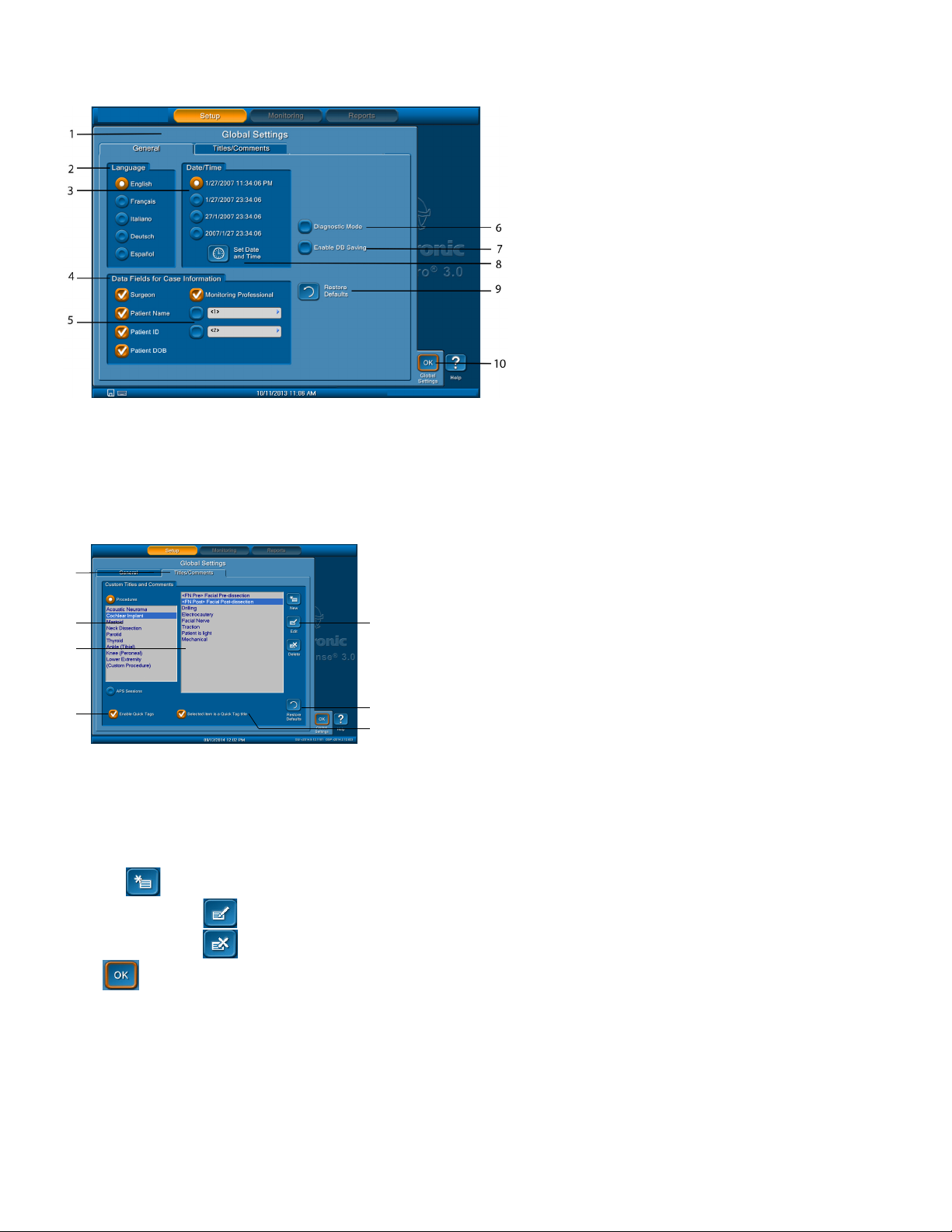
Global Settings
You can access the Global Settings panel by pressing the Global Settings button in any of the Setup Mode screens.
1 Global Settings screen
2 Language tab
3 Date /Time tab. Select how the system displays the
date/time. The default format is language sensitive.
4 Data Fields for Case Information tab
5 Blank data elds. Enables you to name two elds which
will appear on the Case Information screen.
6 Diagnostic Mode. Not for end users. This selection
should only be used under the direct supervision of
Medtronic Xomed personnel.
7 Enable DB Saving check box (default is unchecked).
Turns on the .db option in Reports Mode.
8 Set Date and Time button. Opens a data entry key pad
for setting date and time.
9 Restore Defaults button. Restores all settings, including
procedure settings, to their defaults.
10 OK button closes the Global Settings screen.
Add/Maintain Custom Titles and Comments on the Global Settings Screen
This feature enables you to create new titles/comments or delete entries that have already been created including the default titles. The Edit and
Delete buttons appear when you select an existing item in the list. The titles/comments are grouped by procedure type as selected by the radio
buttons on the left.
1 Title/Comments tab
1
2
3
4
2 List box containing procedure names
3 List box containing pre-dened titles for the selected procedure
4 Enable Quick Tags check box
5
5 New, Edit, and Delete buttons
6 Restore Defaults button
7 Selected item is a Quick Tag title check box
6
7
1. Select the Titles/Comments tab on the Global Settings screen.
2. Select a procedure from the list box on the left of the Custom Titles and Comments panel. A list of titles for the selected procedure appears in
the list box to the right.
3. Do any of the following:
• Press to create a custom title/procedure. Use the on screen or attached keyboard to type a title or comment.
• Select a title, press , and then edit the existing procedure.
• Select a title, press . The system deletes the title.
4. Press .
The system saves your settings.
15
NIM-Neuro 3.0 and NIM-Response 3.0
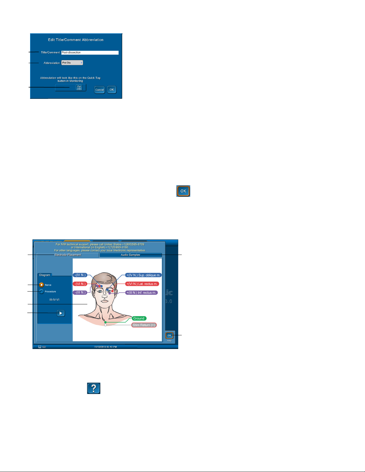
Quick Tags
1 Title/Comment text box. By default, the procedure title you selected on the Titles/
Comments tab appears.
1
2
3
You can use the Enable Quick Tags check box to type an abbreviation of the title that appears on a quick tag button on the tool bar at the bottom
of the screen during the Monitoring phase. You can activate a quick tag by selecting a title and then select “Selected item is a Quick Tag title”
check box. Once you have selected from the drop down menu, type an abbreviation for the title of the button using the pop-up that appears.
1. Refer to the Add/Maintain Custom Titles and Comments on The Global Settings Screen topic to select a title.
2. Select the Enable Quick Tags check box.
3. Select the Selected item is a Quick Tag title check box.
The Edit Title/Comment Abbreviation pop up appears with the title/comment name in the Title/Comment box.
4. Press the Abbreviation box.
The Abbreviation pop up appears with the choice to use an on screen keyboard, or use your attached keyboard.
2 Abbreviation text box
3 Example of the Quick Tag you created.
5. Type the abbreviation you want to use for your quick tag and press .
The Abbreviation pop up disappears and the system returns you to the Edit Title/Comment Abbreviation pop up with an example of how
your quick tag button will appear on the Monitoring screen.
Help
The Help screen displays help graphics for locating electrodes or sample audio sounds.
1 Electrode Placement tab. Selects help graphics for locating
1
2
3
4
5
6
7
You can use the Help screen to view electrode placement graphics to aid in electrode placement and sample audio sounds.
View Electrode Placement Using the Help Screen
You can use the Electrode Placement tab on the help screen to view electrode placement graphics.
electrodes.
2 Diagram/Nerve radio button. Selects help graphics by nerve
number/name.
3 Diagram/Procedure radio button. Selects help graphics by
Procedure.
4 Graphics display area
5 Previous/Next buttons. Use these buttons to change graphics.
6 Audio Samples tab. Contains three sample sound buttons
(pulse, train, burst).
7 OK button. Closes Help screen.
1. On the Setup screen, press .
The Help screen appears with the Electrode Placement tab showing.
2. On the Diagram panel, select one of the following:
• Nerve – to view electrode placement by nerve number/name.
• Procedure – to view electrode placement by procedure.
16
NIM-Neuro 3.0 and NIM-Response 3.0
3. Use or to move through available placement help graphics.
4. Place electrodes according to the appropriate help graphic.
5. Press to return to the Setup screen.
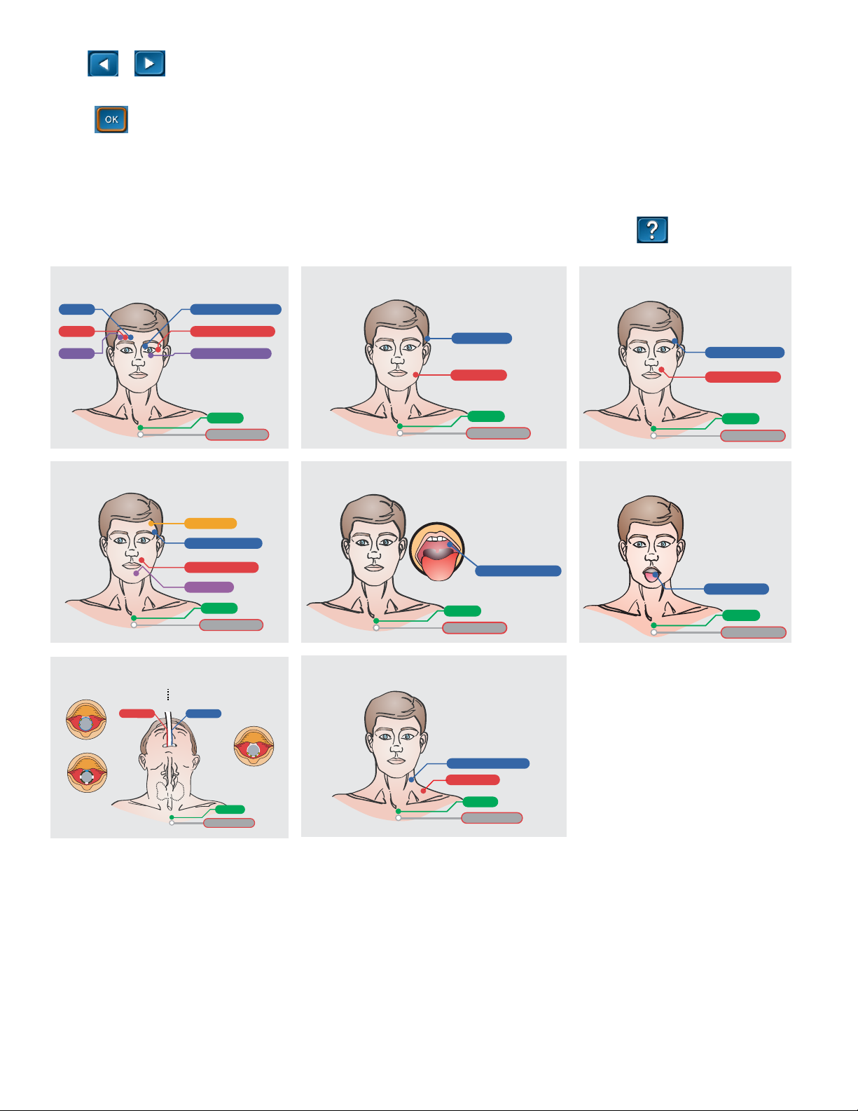
Electrode Placement
The surgeon will insert electrodes into the appropriate muscle location innervated by the monitored nerve. Additionally, you need a ground
electrode (green) and a stim return (white) to complete the electrode setup. NIM 3.0 systems include nerve and electrode placement guides that
are color-coded to help reduce confusion.
This page of electrode placement guides contains some, but not all, possible electrode placements. Refer to the button on the NIM screen
for an additional list of electrode placement guides.
Extraocular Cranial Nerve III, IV, VI
-(IV N.)
-(VI N.)
-(III N.)
+(IV N.) Sup. oblique m.
+(VI N.) Lat. rectus m.
+(III N.) Inf. rectus m.
Ground
Stim Return (+)
Facial Cranial Nerve VII - 4 Ch.
Frontalis m.
Orbicularis Oculi m.
Orbicularis Oris m.
Mentalis m.
Ground
Stim Return (+)
Vagus Cranial Nerve X
Right Left
Vocalis 2
Vocalis 1
Trigeminal Cranial Nerve V
Temporalis m.
Masseter m.
Ground
Stim Return (+)
Glossopharyngeal Cranial Nerve IX
Glossopharyngeal m.
Ground
Stim Return (+)
Spinal Accessory Cranial Nerve XI
Facial Cranial Nerve VII - 2 Ch.
Orbicularis Oculi m.
Orbicularis Oris m.
Ground
Stim Return (+)
Hypoglossal Cranial Nerve XII
Hypoglossal m.
Ground
Stim Return (+)
NIM® Standard Tube
™
NIM Contact® Tube
TubeNIM TriVantage
Ground
Stim Return (+)
Sternocleidomastoid m.
Trapezius m.
Ground
Stim Return (+)
17

NIM-Neuro 3.0 and NIM-Response 3.0
Listen to Audio Samples
You can use the Audio Samples tab on the help screen to hear three types of audio alarms.
1. On the Setup screen, press .
The Help screen appears with the Electrode Placement tab showing.
2. Select the Audio Samples tab.
3. Select any of the following audio samples:
• Pulse
• Train
• Burst
4. Press to return to the Setup screen.
Place Electrodes Step 2 of 2 Screen
The system automatically opens this screen after you select a factory installed procedure.
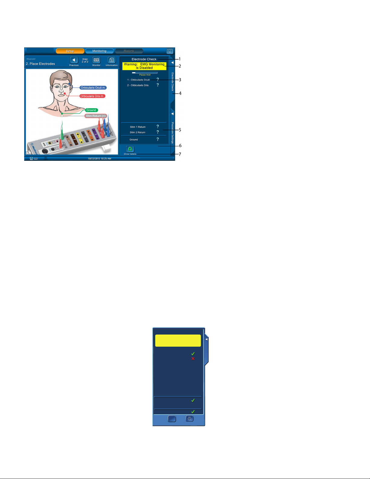
The Place Electrodes Step 2 of 2 screen assists you with electrode location. When the system runs an electrode check, this screen shows the
electrodes the system is testing.
Note: If you make changes to the procedure and want to save them, then you must make the changes before selecting the Monitor or
Monitoring button.
Note:
• You can bypass this screen by selecting the Monitor or Monitoring button.
• If you bypass the screen, no pre-surgery impedance values of the electrodes, ground, or STIMreturns are available for printed/saved
reports.
• If the patient interface, electrodes, ground, or STIMreturns were disconnected when you opened this screen, any printed report will show
a failure of the impedance values of the disconnected item(s).
1 Tool Bar. Allows selection of available functional modes.
2 Monitor button opens the Monitoring screen. Note: If you
make changes in the Electrode Check panel, the Procedure
Settings panel, or one of the Procedure Settings/Advanced
Settings Tabs, a dialog box opens asking if you wish to save
your changes.
3 Previous arrow button. Returns you to the Select Procedure
screen.
4 Setup wizard navigation bar
5 Electrode Placement Graphic. Shows electrode placement
for the patient and patient interface.
6 Information button opens the Case Information screen.
7 Electrode Check tab. Closes/Opens Electrode Check panel.
8 Procedure Settings tab. Opens/Closes Procedure Settings
Panel.
Electrode Check
The Electrode Check screen checks the integrity of the patient to Patient Interface connections. It is the only screen where you can adjust the
electrode type in use.
18
NIM-Neuro 3.0 and NIM-Response 3.0
Electrode Check Panel
You can access this panel from two (2) locations: In Setup Mode with Place Electrodes screen (shown below), or from the Monitoring screen by
pressing control panel tab and Electrode Check button.
1 Electrode Check Panel typically appears in Setup Mode with Place
Electrodes Screen. You can open/close the Electrode Check Panel
using the Electrode Check tab.
2 The system disables monitoring when the Electrode Check panel
is open.
3 Electrode status eld:
• Progress bar. Appears while the system tests electrodes.
• Question Marks. Question marks appear while the system
runs the electrode test and are replaced with pass (green
check mark) or fail (red x mark) once the system has
completed the test.
4 Closes Electrode Check panel.
5 STIM1, STIM2, and Ground status elds.
Note:
• There is no STIM status (blank) if you select Bipolar on the
Type Panel
(located in the Advanced Settings/Stimulation Panel).
• There is no STIM2 status (blank) if a single stimulator is
connected.
• STIM2 appears after you turn it on using the Activate
button located on the main screen, or by selecting the
STIM2 or APS™ check box on the Procedure Settings/
Stimulation Panel.
• STIM 1, STIM 2, Ground - If a question mark appears after
the system has completed the test, no channel electrode
or ground was connected so the system reads that as no
value (impedance). You must connect at least one channel
electrode and ground for the system to read STIM 1, STIM
2, and Ground impedance.
6 Print or Save button appears in this area. Sends monitoring
electrodes, ground, and STIM 1 and 2 return impedance values to
the printer or USB drive.
Note: Print button appears only if a printer is connected. The
Save button appears if a USB device is connected.
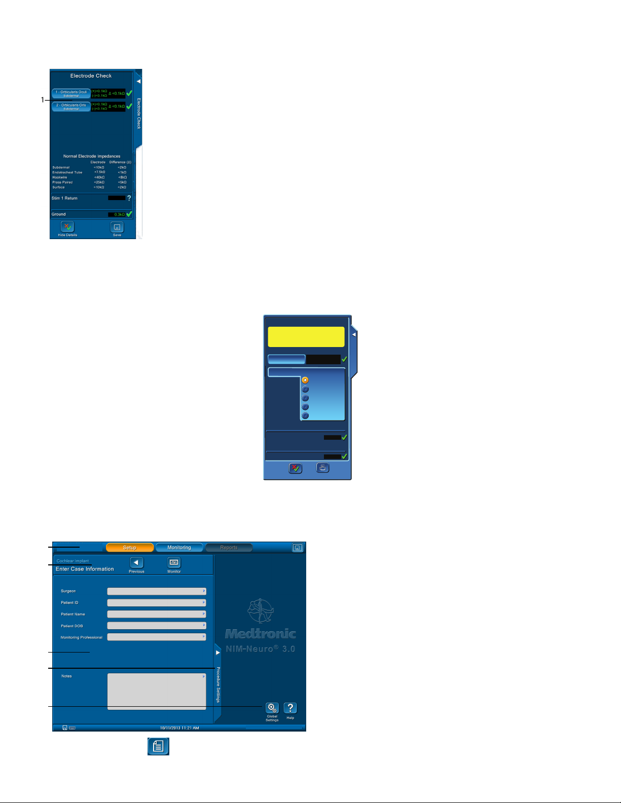
7 Show Details button. Refer to the Electrode Check Show Details
Panels topic.
Electrode Check Panel Pass/Fail
The system measures impedance values of the electrodes to the patient to conrm the integrity of the connection.
Electrode Check
Electrode Check
Warning: EMG Monitoring
is Disabled
Electrode Check
Electrode Check
1 - Orbicularis Oculi
1 - Orbicularis Oculi
2 - Orbicularis Oris
2 - Orbicularis Oris
Stim 1 Return
Stim 1 Return
Ground
Ground
Ω
Ω
Print
Show Details
Show Details
Print
This screen shows that channel 1, stimulus return, and ground electrodes have passed where channel 2 has failed.
19
NIM-Neuro 3.0 and NIM-Response 3.0
1
Hide Details
Hide Details
Print
Electrode Check Show Details Panel
Press the Show Details button to see the actual impedance values. Refer to the “Troubleshooting” topic for more information.
1 Electrode Type Button.
Note: When you select the Details view, the system displays the normal electrode impedance limits if the number of channels is less than six.
Electrode Type Panel
Use the Radio Buttons on the Electrode Type screen to select the type of electrode you want to use. Refer to the “Troubleshooting” topic for
information on electrode troubleshooting.
Electrode Check
Electrode Check
Warning: EMG Monitoring
is Disabled
Subdermal
Subdermal
1.5kΩ
1.5kΩ
0.7kΩ
0.7kΩ
(+) 5.9kΩ
(-) 5.9kΩ
(+) 6.0kΩ
(-) 55.8kΩ
Subdermal
Subdermal
Endotracheal Tube
Endotracheal Tube
Hookwire
Hookwire
Prass Paired
Prass Paired
Surface
Surface
Print
1 - Orbicularis Oculi
1 - Orbicularis Oculi
2 - Orbicularis Oris
2 - Orbicularis Oris
2 - Orbicularis Oris Electrode Type
2 - Orbicularis Oris Electrode Type
Stim 1 Return
Stim 1 Return
Ground
Ground
∆ 0.0kΩ
∆ 48.2kΩ
8.1kΩ
6.6kΩ
Electrode Check
Electrode Check
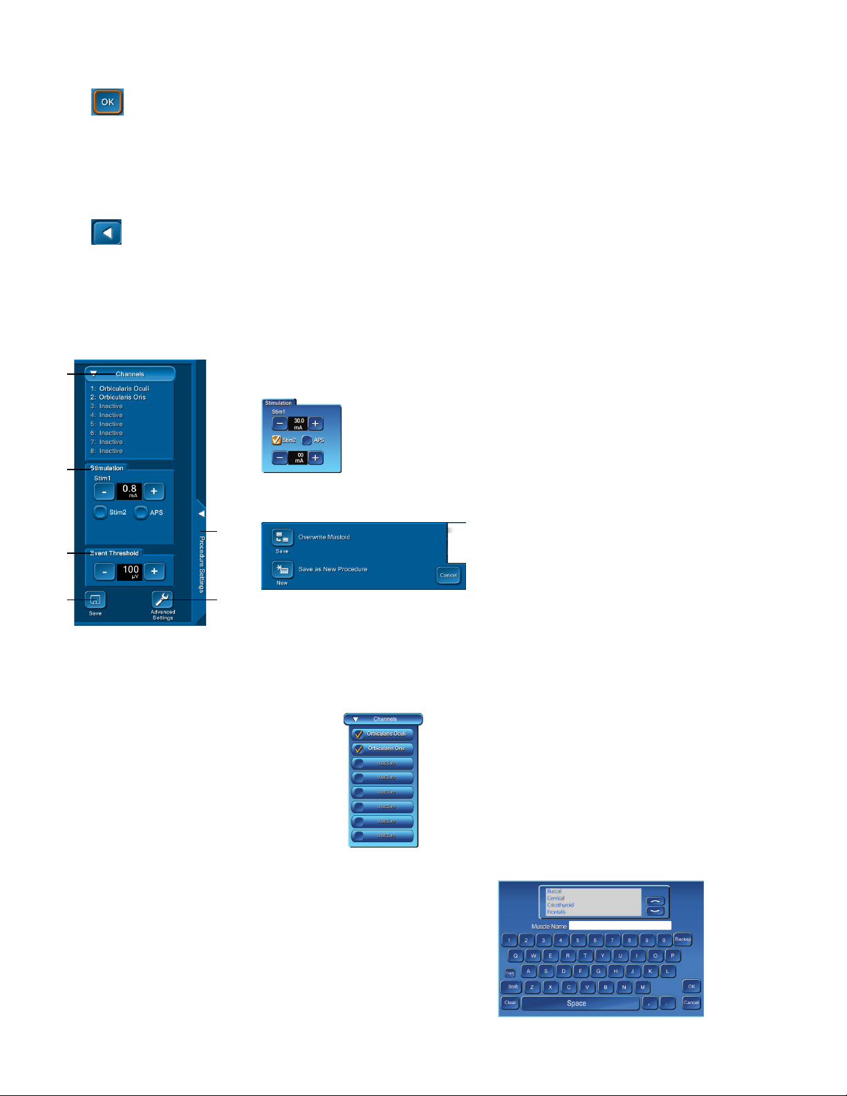
Case Information
The Enter Case Information screen opens when you press the Information button. Use this screen to enter data into preselected data elds. Refer
to the Global Settings topic for data eld selection.
1 Tool Bar. Select any of the three major functional Modes.
2
3
4
2 Setup Wizard Navigation Bar. The Previous and Monitor buttons
are located here. Refer to the Buttons and Indicators topic for
more information.
3 Case Information. Press any of the information elds to open the
keyboard for data entry.
4 Procedure Settings Tab. Opens Procedure Settings panel.
5 Global Settings and Help Buttons. Refer to the Global Settings
topic for more information.
5
1. On the Setup screen, Press .
20
NIM-Neuro 3.0 and NIM-Response 3.0
The Enter Case Information screen appears.
2. Press the Surgeon box and type the surgeon information using the on screen or attached keyboard.
3. Press .
4. Repeat steps 2 and 3 for the following information:
• Patient ID
• Patient Name
• Patient DOB
• Monitoring Professional
• Notes
5. Press .
The system returns you to the Setup screen.
Procedure Settings Panel
You can only access the Procedure Settings panel through the Setup Mode.
Note: You can save your changes on this panel (save to a new or existing procedure). You can review and/or change the monitoring settings for
the procedure.
1
2
3
4
1. Press the Channels button to access a drop down list of channels.
1 Channels. Add, remove, or change the names of the channels.
2 Stimulation Panel. Adjust STIM1 stimulus and STIM2 or APS stimulus (if selected).
3 Event Threshold Panel. Adjust the event threshold, which has a range from 20μV to 2500μV.
4 Save Button
5
6
5 Procedure Settings tab. Opens/closes Procedure Settings panel.
6 Advanced Settings Button
• Opens save option panel.
• Save option panel gives you the option to overwrite the existing procedure, create a new
procedure, or cancel.
2. Press an active channel to inactivate that channel. Press an inactive channel to open the Muscle Name keyboard.
3. Use the Scroll buttons to locate an existing muscle group.
4. Highlight the muscle name by touching the screen or type
the new muscle name.
5. Press OK
The system saves the muscle name and exits.
21
NIM-Neuro 3.0 and NIM-Response 3.0
Advanced Settings
Advanced Settings function:
• You can use Advanced Settings adjustments made during the Setup Mode (Procedure Settings Panel) for the current or saved session.
• Advanced Settings adjustments made in the Monitoring Mode (Control Panel) are only eective for the current session and cannot be
saved.
When you press the Advanced Settings button, the system opens a screen with tabs that enable access to the functions described.
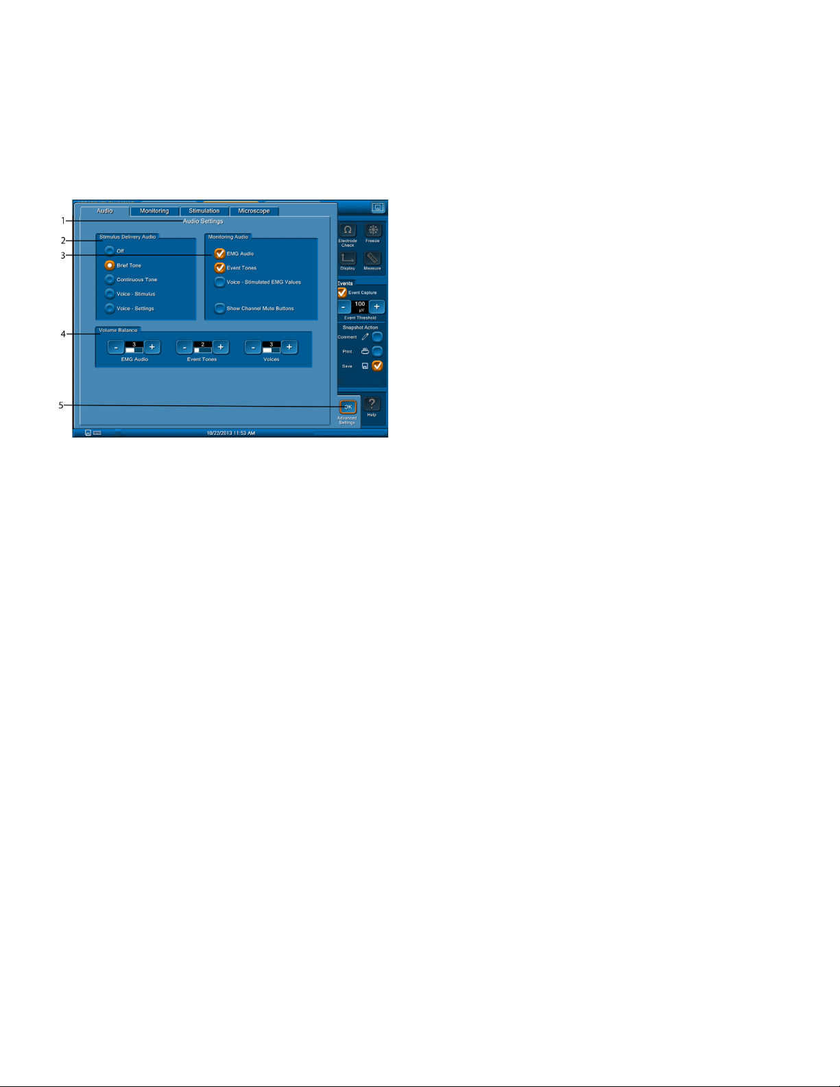
Audio Tab
Refer to the Audio – Understanding What You Hear topic for more information on the Audio tab.
1 Audio Settings. Congures system to determine what sounds will be
heard during monitoring and balance between various sounds.
Note: If APS is active, the Event Tones volume balance will control the
APS volume balance.
2 Stimulus Delivery Audio panel
3 Monitoring Audio panel
4 Volume Balance panel. You can adjust Sound levels using the + and –
buttons for EMG Audio, Event Tones and Voices. A numeric value and
white bar graph indicate the setting relative to full scale (scale is 1 to 5).
5 OK button. Closes the Advance Settings panel.
Additional options for the Stimulus Delivery Audio panel (2):
• Brief Tone (default). Delivery of stimulus current is accompanied by a brief warbled tone.
• Continuous Tone. Delivery of stimulus current is accompanied by a continuous, warbled, high-low tone (referred to as “Stimulus Warble
Tone”).
• Voice - Stimulus. Delivery of current to the surgical eld is announced by the word, “STIMULUS”.
• Voice - Setting. Delivery of current to the surgical eld is announced by the value of the stimulus setting.
Note: You will not hear the Stimulus Delivery Audio when an event has occurred.
The following options are located on the Monitoring Audio panel (3). At least one selection must be active, however you may select both
options.
• EMG audio is the amplied sound of muscle activity that is heard instantaneously as the nerve is stimulated. All EMG activity, regardless
of amplitude, is audible when the EMG audio is ON. The EMG activity may sound like a low-pitched “drumbeat”, a high-pitched “crackle,”
or a “growl”. When you monitor multiple channels, it is unlikely that you will be able to dierentiate the EMG signals as to their channel of
origin strictly by the sounds they produce.
• Event Tones are heard when the EMG amplitude is larger than the Event Threshold setting. The Event Tones are easily heard over O. R.
noise and are heard at the same time with the EMG audio, previously mentioned.
• If you selected “Voice – Stimulated EMG Values” in Advanced Settings/Audio, the NIM announces the value of the highest channel in
the last or largest event in a sequence (one second after the sequence ends). The system rounds the actual value appropriately for
annunciation. For example, the system would announce 623 as “six hundred twenty.”
You can dierentiate channels by tone pitch. The tone for channel 1 activity is lower in pitch than channel 2, and so on for channels 3 through 8.
When EMG activity exceeding the event threshold occurs at the same time on multiple channels, only the tone of the channel with the highest
EMG activity will be produced.
You can mute individual EMG channels by selecting Show Channel Mute Buttons.
22
NIM-Neuro 3.0 and NIM-Response 3.0
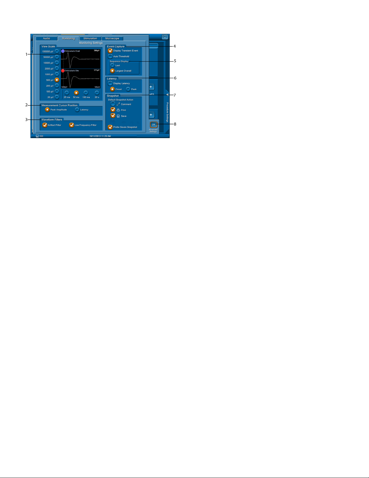
Monitoring Tab
1 View Scale. Refer to the Control Panel Display Button.
2 Measurement Cursor Position panel.
3 Waveform Filters panel
4 Event Capture panel
5 Sequence Display panel
6 Latency panel
7 Snapshot panel
8 OK button. Closes the Advanced Settings panel.
In the Measurement Cursor Position panel (2), you can select the following measurement start positions:
• Peak Amplitude - selects the largest peak value
• Latency - places the cursor where the response to a stimulation begins.
There are two types of Waveform Filters (3):
• Artifact Filter: Selecting this Check Box enables the detection of artifact as “Spiked Waveforms” .
• Low Frequency Filter: Low Frequency Response is generally caused by the movement of the electrodes, electrode wires, tissue etc. This can
result in a response that is not a true EMG response. Selecting this Check Box enables a lter that reduces Peak to Peak amplitude (about
20%) in a frequency range below 70Hz reducing unwanted response. The lter is on by default for all procedures.
If you selected the Auto Threshold check box in the Event Capture panel (4) and the Event Tones are continuous for 10 seconds:
• Auto Threshold automatically calculates a new Event Threshold (to a maximum of 400μV).
• You will hear all activity less than the new Event Threshold as raw EMG.
• EMG activity greater than the new Event Threshold or greater than 400μV generates Event Tones.
• Additionally, if you selected the Voice setting, it announces the amount of threshold increase.
• The Event Threshold returns to the original value after 10 – 20 seconds of no, or decreased, event activity.
In the Sequence Display box (5), the Last box is selected by default. The following happens:
• If Last and Event Capture (see Control Panel) are selected, the most recent event appears until replaced with a new or more recent event.
• If Largest Overall and Event Capture (refer to the Control Panel topic) are selected, and multiple events occur over a period of 4 seconds,
then the largest event from the series of events appear as Largest x of x (example 3 of 5).
• This remains on screen until replaced with the next event or next largest event from a 4 second series of events.
Note: Neither Event Capture nor Largest are available when the x-axis time scale is set to 20 seconds (it is only available in the 50ms time scale).
On the Latency panel (6), you can do the following:
• Control whether the system shows latency values in non-APS stimulated waveform sweeps using the Display Latency check box.
• Control whether the system measures latency to the onset of the response, or to the highest peak EMG value of the response using the
Onset or Peak check boxes.
• If you selected Display Latency in Advanced Settings, then for every stimulation pulse that causes a response greater than 20 µV, the
system displays the Latency value on the waveform. It may be measured to the onset of the response or to the highest peak EMG value of
the response, depending on the settings you chose.
On the Snapshot panel (7), you can do the following:
• Choose the default snapshot actions using the Comment, Print, and/or Save check boxes. You can select more than one action.
• Select the Probe Saves Snapshot check box to control whether the center position on the incrementing stimulus probe saves a snapshot.
• If the center button is enabled and the Comment button is checked, then when you press the center probe button:
• The title/comment box pops out.
• One of the titles in the list is selected.
• The up/down buttons on the probe now do not change the stim current, but rather move the highlight bar up and down the title list.
• When the desired title is selected, the center button moves the selected item into the Event Title, save/print the snapshot and close
the title/comment box.
23
NIM-Neuro 3.0 and NIM-Response 3.0
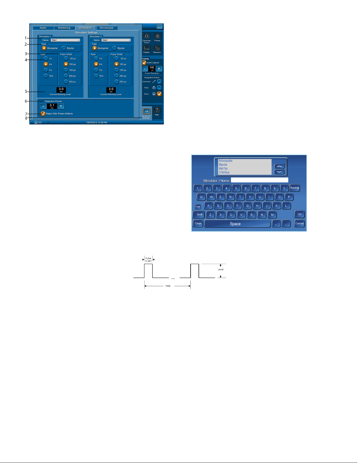
1 Name/text eld
2 Type Panel. Use this panel to select either the monopolar or bipolar
3 Pulse Width panel. Use this panel to make adjustments to the
4 Rate panel. Use this panel to make adjustments to the stimulus rate.
5 Current Warning Level. This is the maximum stimulator current setting
6 Rejection Period panel
7 Reject Stim Pulse Artifacts check box
8 OK button. Closes the Advance Settings panel.
Identify STIM 1 and STIM 2 Names
1. Press the text box next to the Name eld under the Stimulator 1 or 2
panel to open the Stimulator 1 (or 2) Name keyboard.
2. Press the Stimulator 1 (or 2) Name box.
3. Use the Scroll buttons to locate an existing probe.
4. Highlight (touch the screen) the probe name.
5. Press OK, or type the new name.
The system saves the probe name and exits.
6. Repeat for Stimulator 2 panel.
probes. Monopolar is the default. If you are using bipolar probes, you
must change the probe type at this location.
stimulus pulse width.
before a warning dialog appears.
Note: Use this area if you accessed this screen from Setup/Procedure
Settings/Advanced Settings. No adjustment is available if you
accessed this screen from Monitoring/Control Panel/Advanced
Settings.
The following is an example of a pulse width and rate adjustment performed on the Pulse Width (3) and Rate (4) panels.
Pulse width and Rate diagram (number of pulses per second)
Note: If you selected an APS procedure, then the Stimulator 2 Panel/Rate adjustment will be located on the APS Tab.
Use the Rejection Period panel (6) to do the following:
• Adjust the rejection period using the Rejection Period + or - buttons.
• Suppress the stimulus pulse artifacts during monitoring by selecting the Reject Stim Pulse Artifacts check box (7).
Stimulus Artifact Example
The Stimulus Rejection Period enables you to lter the Stimulus Artifact (electric noise caused by stimulation) and all other signals in this period.
Stimulus artifact is a monitoring term for an artifact created by stimulus voltage delivered to the patient, which is picked up as feedback either
internally or externally to the monitoring equipment. It is normally small and does not impact monitoring but can, under certain conditions,
be displayed and sounded on the monitor. It is important to understand the NIM system’s visual and audio feedback so as not to confuse the
stimulus artifact with real EMG, or recognize if both the stimulus artifact and real EMG are present at the same time.
The on-screen stimulus artifact, when it appears on the monitoring panel display, is seen as an event (above or below threshold) which starts
directly after the stimulus on the left side of the screen and proceeds for a duration into the EMG waveform detection area. The level of the
artifact is directly proportional to the stimulus delivery and cannot be EMG because nerve signals need time propagate.
The stimulus artifact sound is the audio representation of stimulus artifact. It is a high frequency sound similar to cymbals and sounds like “ti - tchi.” It is unlike an EMG sound which is similar to a drum sound.
24

NIM-Neuro 3.0 and NIM-Response 3.0
a. Original Rejection Period setting.
b. Stimulus Artifact.
c. Move Rejection Period line to here to avoid artifact.
d. EMG Response.
Note: In previous versions of the NIM, Stimulus Rejection Period was referred to as Stimulus Artifact or Artifact Delay.
Special Note on Recognizing Artifact
The NIM 3.0 System features sophisticated artifact rejection technology designed to provide highly sensitive and accurate monitoring.
However, there may be electrically generated signals in the range of true response that the NIM 3.0 System cannot dierentiate. Refer to the
“Troubleshooting” topic for more information.
Examples:
• A transcutaneous stimulator used by the anesthesiologist might generate an audible signal.
• Any external nerve locator/stimulator not synchronized (Muting Detector) with the NIM 3.0 System.
• Electrical leakage from faulty thermal cautery units. You can identify the spurious signals by their lack of surgical context (there was
nothing the surgeon was doing at that moment that could have caused a true EMG response).
• If the recording electrodes and the stimulator (+) or (-) cables become tangled the resulting stimulus artifact might be spuriously detected
as an EMG event. Be careful to route the recording electrodes away from stimulator cables.
• If/when wires must cross, they should cross at right angles. Never run other operating room cords/cables parallel to any of the NIM 3.0
System wires. If/when wires must cross, they should cross at right angles.
• The pace pulse generated by pacemakers may be detected and displayed by the NIM 3.0 System as a rhythmic artifact signal. This is
caused by the electrode ground or stimulus return electrodes being in close proximity to the pacemaker or its lead wire(s). The artifact
caused by the pacemaker may be reduced by repositioning the Electrode Ground and Stimulus Return electrodes to the top of the
patient’s shoulder (the Acromion) (use shoulder opposite operated side). The Electrode Ground (green plug green wire) and Stimulus
Return (red plug white wire) electrodes should be positioned about 5 cm apart, green Proximal, red Distal. Once the electrodes are
repositioned, verify that the Stimulus Return and Ground Impedances are within tolerance (review Setup Mode/Electrode Check ).
• There may also be interference-generated signals in the range of true response that the NIM® 3.0 System cannot dierentiate. An example
of this type of artifact signal could occur when the surgeon strikes two metal instruments together within the surgical eld, such as a
metal suction tube with a dissecting tool. Such signals are typically monophasic with fast onset and oset. That is, the signals appear on
the screen as sharply peaked responses in one direction only.
• While these artifacts are signicantly dierent in waveform appearance from true EMG events (which have a biphasic waveform), the
magnitudes of these signals can reach several hundred microvolts causing the event tone to sound. However, the surgeon is usually aware
when two instruments have been struck together and can, therefore, relate such “false positive” responses to the surgical context.
Important Note on Stimulator Adjustments
By selecting a procedure, the default settings for stimulus intensity normally provide adequate stimulation. The absolute stimulus intensity
required to adequately stimulate any motor nerve is determined by a complex combination of several factors including (but not limited to) the
following:
• The functional health of the nerve itself.
• The type of stimulation probe used (monopolar or bipolar).
• Proximity to the nerve.
• The pulse width of the stimulus.
You should use the amount of stimulation necessary to elicit a detectable EMG event. Stimulus current levels of 0.3mA may be high enough
for adequate direct monopolar stimulation of the facial nerves, but may elicit little or no response when monitoring nerves during thyroid
procedures. The best guideline for setting the stimulus intensity level is to use the lowest amount that produces an EMG event. Under- and overstimulation are covered under W19, W20, and W27 in the “Warnings” topic.
25
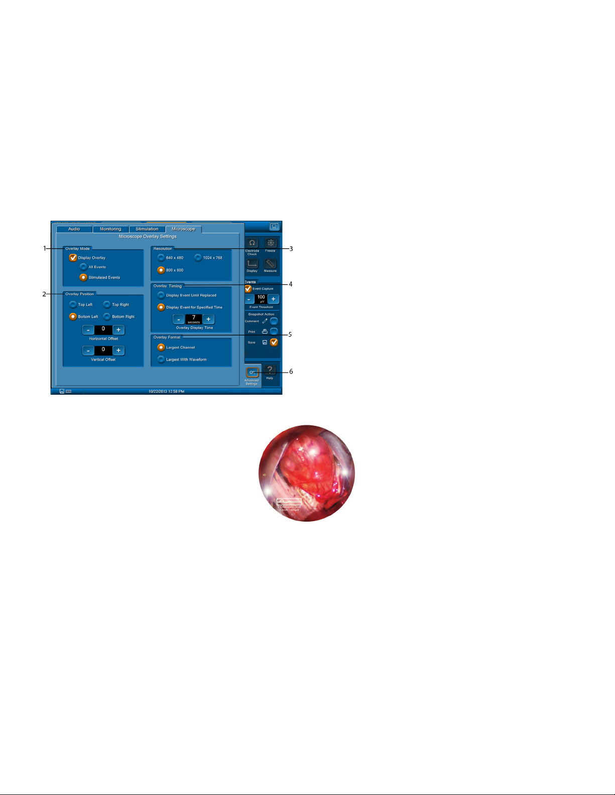
NIM-Neuro 3.0 and NIM-Response 3.0
The surgeon should be aware:
• That STIMULUS is continuously being applied to the STIMULATOR probe and/or the APS.
• STIMULATING the patient is the result of physical contact between the patient and the STIMULATOR probe.
• The STIMULATOR probe should be kept ISOLATED when NOT STIMULATING the patient (except APS).
Note: Stimulator adjustment involves the adjustment of the Current, Rate, Pulse Width, and the Stimulus/Rejection Period.
Note: To prevent inadvertent high stimulus levels, the rst time the stimulus level exceeds the Current Warning Level (5), a dialog box opens:
• Stimulus in excess of the current warning level (usually 3 mA).
• Press OK to allow stimulus
If using the procedures Lower Extremity, Knee, or Ankle, the stimulus level warning is set at 12.0 mA.
Microscope Tab (available on the NIM-Neuro 3.0 only)
Note: When the “Display Overlay” check box is not checked, the system does not display all other parts of the panel.
The following graphic shows all default settings.
Note: Not all video input microscopes are compatible with the NIM® 3.0 System. Contact Customer Care at 1(800) 874-5797 for specics.
1 Overlay Mode panel
2 Overlay Position panel
3 Resolution panel
4 Overlay Training panel
5 Overlay Format panel
6 OK button. Closes the Advance Settings panel.
Use the Display Overlay selection on the Overlay Mode panel (1) to activate the microscope overlay video output.
Example
You can select between displaying any event or events resulting from stimulation.
Use the Overlay Position panel (2) to select where the system displays the overlay.
Location is ne tunable at plus or minus 60 pixels using the horizontal or vertical oset adjustment.
The resolution (3) should be set to the value specied by the microscope manufacturer.
Use the Overlay Training panel (4) to display an event until replaced with a new event, or have the display turn o after a selected period of time.
Select the Largest Channel radio button on the Overlay Format panel (5) to select where the system displays show data only or data and
waveform. Example shows data with waveform.
26

NIM-Neuro 3.0 and NIM-Response 3.0
APS Tab (Automatic Periodic Stimulation)
1 APS Channels panel. Channels 1 and 2 checked by default.
2 Alarm panel
1
2
3 APS Stimulation panel
4 APS EMG panel
5 OK button. Closes Advance Settings panel.
Use the Alarm panel (2) to customize the following alarm settings:
• Amplitude Only sets the alarm to sound if the EMG response tolerance limit is reached regardless of the latency (default is 50% less than
baseline and lower than 2000µV). You can also set an absolute alarm limit in this area.
Absolute alarm limit example: If the baseline amplitude is 3000 μV, the amplitude percentage limit is 50% (1500 μV), and Amplitude
Absolute limit is 1000 μV, then a signal of 1400 μV would not cause an alarm because although the signal has decreased more than 50%, it
is still above the absolute limit.
• Latency Only sets the alarm to sound if the latency tolerance limit is reached regardless of the amplitude (default is latency value plus(+)
10%).
• Absolute Alarm Adjustment. This is an actual EMG voltage response above which the percentage alarm is disabled.
• Amplitude OR Latency sets the alarm to sound if either the EMG amplitude OR the latency limit is reached.
• Amplitude AND Latency only sets the alarm to sound if BOTH the EMG amplitude AND the latency limits are reached.
• The Latency limits button is located to the right of the Increase button and toggles between percent (%) and msec.
• Percentage – this is the percentage increase in latency from the baseline latency at which an alarm condition occurs (for example, if
the setting is 10%, then an alarm occurs when the amplitude goes above 110% of baseline - a 10% increase).
• msec – this is the increase in latency (in milliseconds) from the baseline latency at which an alarm condition occurs (for example, if the
setting is 1.5 msec and the baseline latency is 8.0 msec, then an alarm occurs when the latency goes above 9.5 msec).
Use the APS Stimulation panel (3) to to select a “Slow Rate” and “Fast Rate” . You may switch between these rates when in monitoring. The
default settings for this panel are:
• Slow Rate 10/min (10 per minute)
• Fast Rate 1/sec (1 per second).
• Baseline Rate. You can select the rate at which baseline acquisition occurs from the following values:
• 10/min
• 1/sec
• 2/sec
Note: The Pulse Width adjustment for APS is found on the Stimulation Tab Stimulator 2 panel.
Create a Baseline Measurement for an APS Procedure
You must take a baseline measurement using the Baseline button on the Monitoring screen before you can perform APS trending.
Note: When at least one channel gets a good baseline and any other channel has a median amplitude above the event threshold, the system
continues the baseline stimulation pulses for up to 20 more pulses to enable those channels to meet the criteria before stopping.
1. On the Monitoring screen, press .
The Establishing APS Baseline screen appears displaying the baseline test results.
2. If you received a baseline failure (the system displays the reason for the failure in the gray box), Press to perform a new baseline test.
3. Press .
The system closes the Establishing APS Baseline window, saves your baseline, and returns you to the Monitoring screen.
27
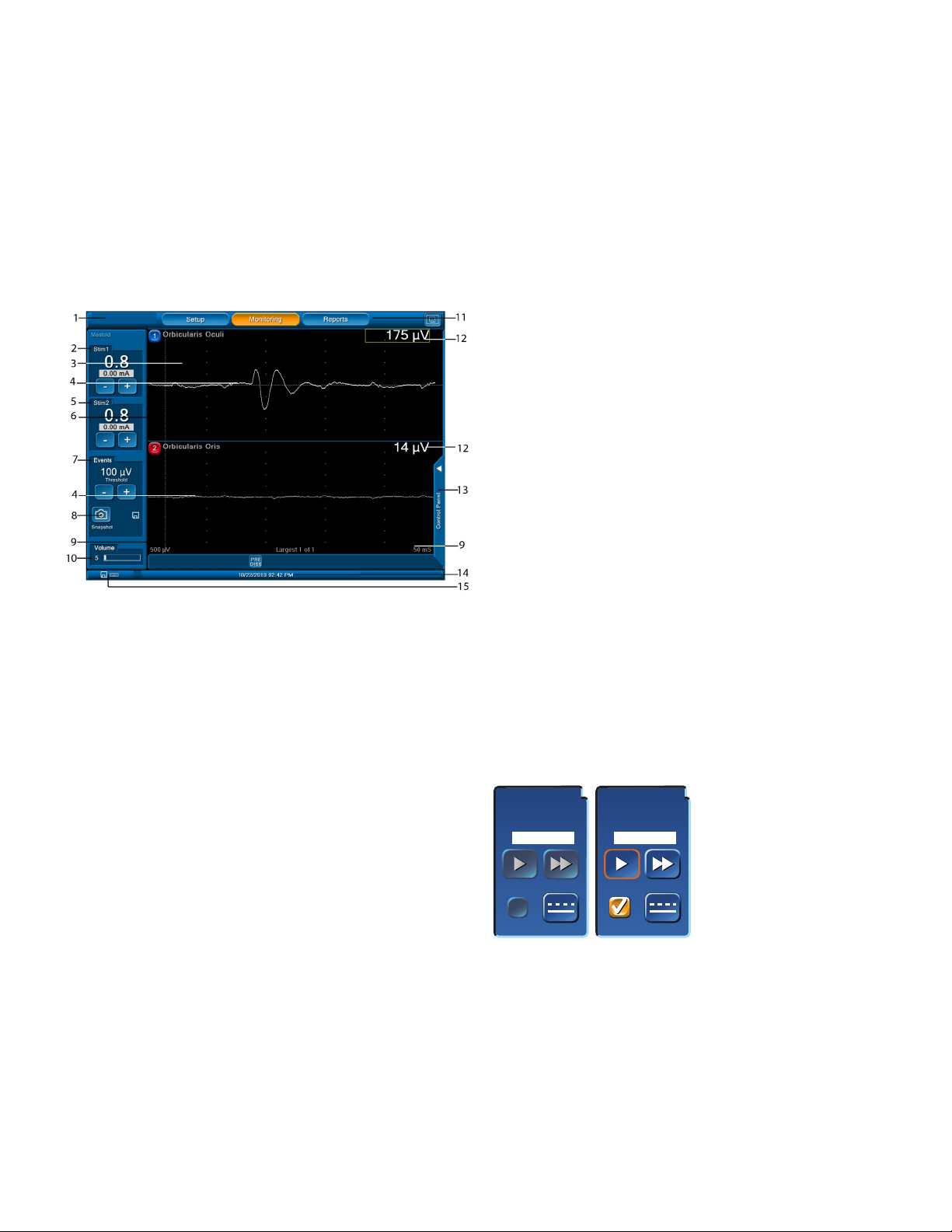
NIM-Neuro 3.0 and NIM-Response 3.0
Vagus APS Stim
Vagus APS Stim
On the APS EMG panel, the Show APS Waveforms check box is selected by default. The system shows the waveforms from APS stimulation on the
Monitoring Screen as blue with EMG response in white. Press the Mute APS EMG Audio to mute the APS EMG Audio (pop, pop, pop sound).
On the APS EMG panel you can control the following audio selections:
• Mute the APS EMG Audio using the Mute check box. If you select the Mute check box, then the EMG audio is muted for the sweeps
initiated by a APS stimulation pulse. If you deselect the Mute check box, then the volume of the EMG audio for APS sweeps is controlled
by the +/- adjustment provided.
• Voice - EMG Values – If you select this check box, then the NIM periodically announces the last APS EMG value audibly. Use the radio
buttons to select the frequency of annunciation.
Monitoring Mode
Access the Monitoring screen by selecting the Monitor or Monitoring button. The Monitoring screen appears during surgery and shows all EMG
activity.
Note: APS is not shown.
1 Tool bar 9 Scale. Displays screen scale
settings.
2 STIM 1 panel 10 Volume panel
3 Channel label. Displays
the channel number and
nerve being monitored.
4 Trace. Displays stimulus
nerve activity/inactivity.
5 STIM 2 panel 13 Control Panel tab
6 Artifact Delay. Shows
where artifact ends and
EMG begins.
7 Events panel 15 Print and Save icons. The
8 Snapshot button
The STIM1 panel (2) displays the following settings:
• Stimulation setting (large numbers)
• Measured value (in the small window)
• Adjustment buttons for the STIM1 current settings.
If the STIM2 panel is inactive, it displays the Activate button. If active as a second stimulator, its display is the same as STIM1.
If an APS procedure has been selected then the APS STIM Panel appears:
Vagus APS Stim
Vagus APS Stim
11 Setup, Monitoring, and
Reports buttons
12 Amplitude
14 Date, Time, GUI, and DSP
version
system automatically
displays these icons (on all
screens with time and date
bars) only if you connect a
USB drive and/or a printer.
1.00
1.00
0.00 mA
Pulse Rate
Pulse Rate
APS On
APS On
Baseline
Baseline
1.00
1.00
1.00 mA
Pulse Rate
Pulse Rate
APS On
APS On
Baseline
Baseline
• The APS On, check box, Slow Rate, and Fast Rate buttons will be inactive (gray) until after the APS Baseline has been established.
• Refer to the APS Tab section in the Setup Mode topic for how to establish a baseline.
28
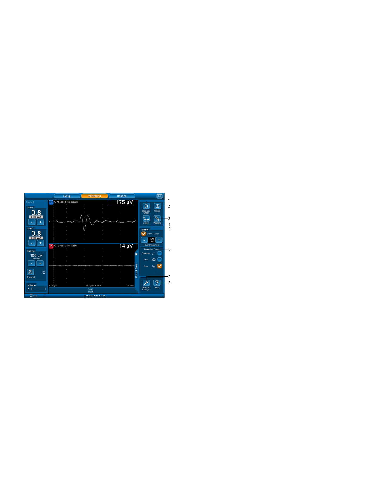
NIM-Neuro 3.0 and NIM-Response 3.0
Events Panel
The Events panel (7) displays the Event Threshold settings and enables you to adjust the setting level (in 5μV increments).
• EVENT THRESHOLD is used to dene where EMG activity becomes signicant.
• EMG activity exceeding this “THRESHOLD” is dened as an “EVENT” and results in Event Tones.
• Set “Event Threshold” by pressing plus/minus buttons to increase or decrease the value as desired. Setting is displayed in micro-Volts.
Note: Event Threshold adjust buttons are unavailable for APS monitoring. See Control Panel to adjust Event Threshold.
Use the Snapshot Button (8) to save the current screen to memory (for reports), or to a selected peripheral device:
• Comments Icon Snapshot Option. Refer to the Control Panel topic for additional information.
• Print and Save Icon Snapshot Option. The system displays these icons automatically if a USB drive and/or a Printer are connected and you
selected those devices on the Control Panel - Snapshot Action. Refer to the Control Panel topic for additional information.
Note: Snapshots (print or save) show event information only and do not include the impedance values of the electrode, ground, or STIM1/2.
The Volume panel (10) displays an adjustable volume setting.
You can adjust Sound levels using the volume knob on the console’s front panel (see Console Front, Item C). A numeric value and white bar
graph indicate the setting relative to full scale. The default setting is 50.
The amplitude (12) displays activity level in microvolts on each channel:
• A box encloses the activity level of the highest channel.
• If there are multiple channel events, the box encloses the largest.
• If the system detects a signal (response) outside the range of the system’s ability to measure (100,000μV or higher), the system displays
the “Out of Range” message.
Control Panel
Use the Control Panel to access additional settings and monitoring features.
Press the Display button (1) to open the Scale Panel.
1 Electrode Check button
2 Freeze button. When you press the Freeze button, the system
displays the screen content, unchanged, until you press the Freeze
button again. The Freeze button enables you to view an event over
an extended period.
Note: The system does not display any events that take place after
you press the Freeze button.
3 Measure button. Displays a cursor to view details of an event
waveform.
4 Display button
5 Events panel. Select Event Capture box and the system captures
and holds EMG activity that exceeds the Event Threshold setting.
6 Snapshot Action panel
7 Advanced Settings button. Opens Advanced Settings. See Set-Up
Mode/Advanced Settings for information. Adjustments made to
the Advanced Settings in the Monitoring Mode (Control Panel) are
eective only for the current session and CANNOT be saved.
8 Help button. Press the Help button to view an abbreviated
assistance on the Monitor Display.
29
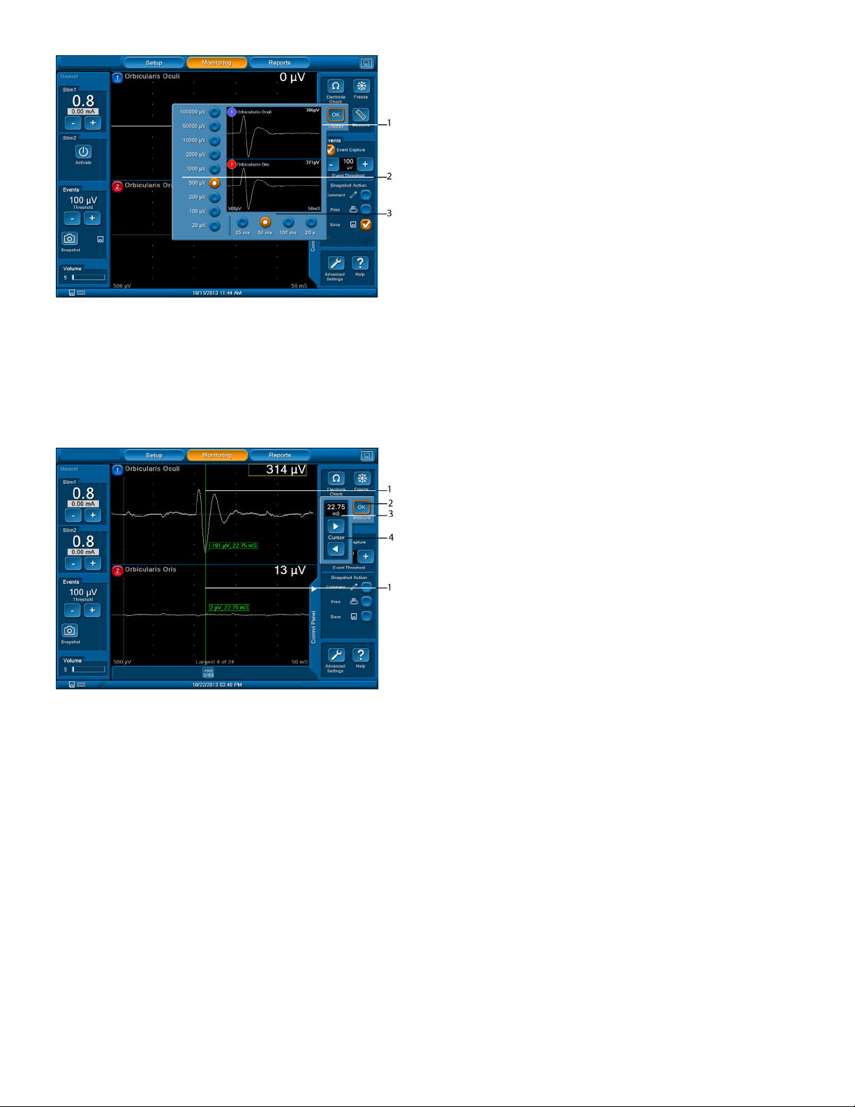
NIM-Neuro 3.0 and NIM-Response 3.0
1 The vertical portion of the EMG display represents peak-to-peak
amplitude. You can adjust the scale. The vertical screen is divided
into equal sections per channel with 1/2 of each channel positive
and 1/2 negative. Each channel is separated by a solid blue line.
2 Time scale is represented by the horizontal portion of the EMG
display and is adjustable (refer to the Advanced Settings /
Monitoring Tab). The screen is divided into equal sections. This diers
from the “Amplitude scale” in that the “Time scale” selection is the
entire horizontal portion of the screen.
3 OK Button, closes Scales panel.
Note: Changing either scale only aects how the data appears on
the screen. It does not modify the sensitivity of the unit.
The following buttons are available on the Events/Snapshot Action panel (6) :
• Comments. Opens comments panel enabling comments and Event Titles (you may enter titles via keyboard or select them from a
customized list) you wish to add to the captured event when you press the Snapshot button. The system displays these comments/title on
the printed and/or saved event. Refer to the Add/Maintain Custom Titles and Comments on the Global Settings Screen topic to customize
this list.
Note: You can modify Comments and Event Titles in Reports Mode.
• Print. Sends captured event to the printer with comments if you selected it when you press the Snapshot button.
• Save. Sends captured event to the USB mass storage device with comments if you selected it when you pressed the Snapshot button.
1 When you activate the Measure button, the on screen cursor (green)
shows the amplitude (μV) and time (mS) at the cursor location.
• Time is measured from zero (0) not from Stimulus/Rejection
Period.
• Amplitude is measured from the channels zero (0) with a
minus (-) sign for negative numbers and no minus sign for
positive numbers.
2 When you press the OK button, the system turns o the cursors and
displayed values.
3 The system displays the time.
4 Cursor Position buttons move the vertical (green line) cursor left or
right in increments of 0.25mS.
The APS Monitoring Screen
APS is a process wherein a nerve at risk is continuously being stimulated. This stimulation is monitored and charted continuously in real time. You
can plot and observe trends.
The plotted characteristics are:
• EMG amplitude (peak-to-peak, response to stimulation)
• Latency (time from stimulation to the “Onset” or peak of the EMG response)
The plotted chart displays peak-to-peak values for EMG amplitude and latency responses for each stimulation pulse delivered. Every turquoise
dot represents a single EMG amplitude response. Each blue dot represents a latency response. A red dot is an out of limit condition resulting in
an alarm sounding.
If a measurement falls outside the limit values, the dots appear red-colored and the console issues an audible alarm to alert you depending on
what alarm settings you selected on the Advanced Settings screen. Alarm mute buttons appear when in an alarm state, enabling you to mute
the audible alarms.
30

NIM-Neuro 3.0 and NIM-Response 3.0
Mute an APS Alarm
When a plotted point falls outside the set alarm limit, the system displays an alarm button on screen. You can mute this APS alarm on the
Monitoring screen using the alarm button.
1. Press .
The system mutes the alarm and displays .
2. To unmute the alarm, press .
If a subsequent plotted point falls inside the alarm limit, the muted button turns green. If the plotted point then falls outside the alarm
limit, the muted button turns back to red. The mute button continues to change between red and green until you turn o the mute button.
1
Waveforms is on (default) in Advanced Settings APS tab.
2 EMG Waveform. Appears as a White Trace on all channels.
3 APS Latency value.
4 APS stimulation level.
5 Values. The system displays the EMG measured values in white with
1 APS Waveform. Appears as a Blue Trace on all channels if Show APS
2
the largest value boxed in yellow.
6 Alarm Mute button. This button shows that an alarm condition is
present.
7 Limit Lines. The system displays the upper limit for Latency and
lower limit for Amplitude as red dotted lines.
8 Baselines. The system displays the Latency and Amplitude as white
dotted lines.
Trend lines. The system displays Latency as a series of turquoise dots
and displays Amplitude as a series of blue dots.
9 Latency and Amplitude are separated by a scaled line. This line is the
time base as shown at top left of screen (L). The scale marks are one
minute apart.
10 Values. The system shows the alarm (if sounded) at the Limit Lines
and and shows the measured value of the last pulse at the Baselines.
11 APS ON check box. Use this check box to pause/continue APS
stimulation once the session has started.
1
12 Time Base.
13 Session duration
2
If the APS button is turned OFF:
• The APS portion of the screen (right side) closes and the system adds an APS tab to the control panel tab. You can open and close the
inactive APS screen using this tab.
• APS monitoring resumes once you select the APS check box.
31

NIM-Neuro 3.0 and NIM-Response 3.0
The Reports Mode
Note: All stored case data (snapshots, log les, APS data, and reports) is lost when unit is powered o.
The Report Mode enables you to quickly compose and print/save three general types of reports; Event Records, Log Files and APS Records. The
system provides report templates to simplify creating reports.
The Reports Mode can be active while audio monitoring continues in the background. The system saves all work performed in Reports mode
if you exit Reports and return to Monitoring. For example, you can start a report midway through a monitoring session. When you return to
Monitoring to complete the session, all previous work is available when you return to the Reports Mode. When you turn the system o, all
monitoring session data is lost.
There are three steps in the process:
• Select Report Format
• Specify Report Content
• Create Report
Select Report Format
The Reports screen is used by Snapshots, Log Files, and APS Records.
1
2
3
4
5
Snapshots/Event Reports
1 Tool Bar. Selects any of the three major functional modes.
2 Active Screen Bar. The system displays the Next button after you
select a report type.
3 Select Case panel. Select a case from multiple cases. The system
displays Next and/or Previous button(s) if more than one case is in
memory.
4 Sample display area of selected report type.
5 Select Report Type panel. Select from available report types.
After you select the Report Type (Snapshots), the Choose Report Content screen appears. Press the Next button on the Active Screen Bar to open
the Create Report screen.
32

NIM-Neuro 3.0 and NIM-Response 3.0
Choose Report Content
APS reports and Snapshot reports are very similar. The dierences are noted in the following.
1 Tool Bar. Select any of the major functional Modes (Setup not
available in Reports).
2 Active Screen bar
3 Choose Events tab (on the APS Reports screen, the Choose Events
panel appears as Choose Sessions panel).
4 Selected Events tab. Shows the collection of events the system
includes on the report.
5 Select All button. Use this button to move all events to the Selected
Events panel (on the APS Reports screen there is no Select All
button).
6 Time-Line panel (on the APS Reports screen there is no time line
panel).
Use the Choose Events tab (3) to:
• Scroll through each captured event (to capture an event, press the Snapshot Button) with the Previous and Next buttons.
• When the system displays an event, you may enter or modify an Event Title or Comment.
• You can move the displayed event to the Selected Events panel by selecting the check box. The system displays Events in the report in the
order you selected them.
• Graphically show all the captured events and time.
• The events you selected to appear on a report appear orange and not-selected events are white.
Generate Snapshots/Events Report Format
Choose a report format and generate (print or save) the report. Depending on the report type, this step takes on dierent looks.
1 Tool Bar. Select any of the major functional Modes (Setup not
available in Reports).
2 Active Screen Bar
3 Report Format panel. Select one record per page or four records per
page.
4 Sample Preview area. Displays an example of the report type
selected.
5 Case Notes box. Add notes to the Report Summary page.
6 Report Options panel
On the Report Options panel (6):
• Print button sends the report to the attached printer.
• Save button sends the report to the attached USB mass storage device.
Saves the formatted report as a .pdf on the USB drive. The system formats the lenames with the report type, year, month, day and time.
For example, EventReport_20090528112530.pdf.
• Reports are located in a Case Folder titled:
• date and patient ID or
• date and patient name or
• with no patient ID or name, the system uses date and sequential case.
33

NIM-Neuro 3.0 and NIM-Response 3.0
Snapshots/Events Reports .pdf Image Example
Note: Record 1 and 2 are “Stimulated” events with STIM1 set value and measured current both showing 0.80mA (printout format is set value/
measured current. Record 3 and 4 are Non-Stimulated events with STIM1 set value showing 0.80mA, and measured current showing 0mA (STIM
1: 0.80/0.00mA). Since no measured current is shown, events are non-stimulated.
Note: Enter Case Notes using the Case Notes text boxes. You entered comments when you pressed the Snapshot button, or when you created
the report.
Select the Log File
The procedure for selecting a log le is the same as the procedure for selecting a report. Refer to the Select Report Format topic for more
information.
Construct the Log File
The system maintains a log le that contains data for all events (not only Snapshot Events) throughout the case. The system creates an event
in the Log File when the EMG value exceeds the Event Threshold value. You can use the data in this le to construct Log File Reports or you can
export the data in comma-delimited format for o-line analysis. For a Log File Report, this wizard step enables you to select event data using
data lters.
1 Tool Bar. Select any of the major (Setup not available in Reports)
functional Modes.
2 Active Screen Bar
3 Event Filter. Choose Events captured using Snapshot or All Events.
4 All Events. Additional lter criteria that enables you to select
Stimulated Events, Non-Stimulated Events, or both.
Note: The All Events panel is visible only if you press the All Events
button.
5 Event Sequences panel
6 Status box. Shows statistics about the logged events, including the
number of events that the system includes in the Report (Selected
Events).
34

NIM-Neuro 3.0 and NIM-Response 3.0
An Event Sequence (5) is a series of events separated from each other by less than one second.
When you select the Sequence Filter (5) you can sort event sequences by Last or Largest:
• Last. When selected, the system includes only the last event in a sequence on the report. This is the default when you press the Sequences
button.
• Largest. When selected, the system includes only the event that contains the greatest value within a sequence on the report.
Generate the Log File
1
2
3
4
5
The following Report Options (5) are available:
• Print button sends the report to the attached printer as a pdf image.
• Save button opens a dialog box enabling you to send the report to the attached
USB mass storage device.
• Save the formatted report to a .pdf image le, .csv data le, or a .db database le on
the inserted USB drive. The system formats the lenames with the date and time, report type
and appropriate extension. For example, LogReport_20090618081932.pdf would be a Log
Report Image created 2009 June 18 at 08:19:32.
• Reports are located in a Case Folder titled:
• date and patient ID or
• date and patient name or
• with no patient ID or name, the system uses date and sequential case number.
1 Tool Bar. Select any of the major functional Modes (Setup not
available in Reports).
2 Active Screen Bar
3 Sample Preview panel shows an example of the report type prior to
saving or printing.
4 Case Notes. Add notes to the Report Summary page.
5 Report Options
1
2
Log Reports .csv (in Excel) Example
1
1
1
Log Reports pdf Image Example
2
2
2
35

NIM-Neuro 3.0 and NIM-Response 3.0
APS Reports
Refer to the Select Report Format topic and select/press APS Reports.
Note: Functionally APS Reports and Snapshot Reports use all the same screens/Panels with the same function. Refer to the Snapshots/Event
Reports topic for instructions.
APS Reports .pdf Image Example
Creating a Report
Snapshots Report
1. Refer to the Select Report Format topic and select/press Snapshots.
The Choose Report Content (Snapshots) screen opens.
2. In the Choose Events panel:
• Select an event you wish to copy to the report using the Next and Previous buttons.
• Press the blue arrow in the white Event Title box to title the event or modify an existing title.
• Press the blue arrow in the white Event Comments box to enter comments about the event or modify an existing comment.
• Press the Include in Report Check Box.
• The selected event appears on the Selected Events panel.
or
Press the Select All Button to move all events to the Selected Events panel. You may still use the Next and Previous buttons to move
through the selected events and enter/modify event titles and comments as needed.
3. Press the Next button on the Active Screen Bar.
The Create Report (Event Records) screen opens.
4. Select one(1) or four(4) from the Report Format panel using the radio buttons.
5. Press the blue arrow in the white Case Notes box to enter comments.
Note: Event Title and Event Comments appear at the top and bottom of the event where they
were entered and in the Summary section of the report. Case Notes only appear in the Summary section.
36

NIM-Neuro 3.0 and NIM-Response 3.0
6. Press the Print and Save button to open a dialog box enabling you to send the report to the attached USB mass storage device.
7. Save the formatted report to a .pdf image le, or .csv data le.
Log Files
1. Refer to the Select Report Format topic and select Log Files.
The Choose Report Content (Log Files) screen opens.
2. In the Event Filter panel:
• Select the Snapshot Events Radio button and only events that were saved when you pressed the Snapshot button on the Main Screen will
be available in the Log File Report, or
• Select the All Events Radio button.
The All Events, and Event Sequences panels open.
• All Events. The system selects Stimulated and Non-Stimulated Events by default. You can adjust these settings to any combination of
the two.
• Event Sequences. Select O (default) if you need to select between Last (default) and Largest.
3. Press the Next button on the Active Screen Bar.
The Create Report (Log Files) screen opens.
4. Press the blue arrow in the white Case Notes box to enter case comments. Case Notes are located between the End of Report and Electrode
Check sections of the Log File.
5. Press Print and/or Save.
Quick Reports
The Quick Reports feature enables you to create a report with certain default features without needing to specify report content each time. The
system saves all settings you select on the Quick Report screen as the default. Some of the group boxes may not be visible (for example, if it is
not an APS procedure, the APS box does not appear). Also, if Enable DB Saving is OFF in Global Settings, the Database box does not appear.
Special Functions and Features
Visual Alarms and Warnings
The operator may encounter the following warnings and should respond appropriately.
37

NIM-Neuro 3.0 and NIM-Response 3.0
Audio – Understanding What You Hear
The NIM 3.0 System Nerve Monitor produces many dierent sounds throughout the surgical procedure that alert you to various important
information. In addition to EMG sounds, the system uses beeps and voices to provide useful information.
Alarms
The alarms draw attention to any condition which prevents you from properly monitoring the surgical procedure. You should not ignore any of
the audible alarms. You must assume that valid monitoring has stopped and determine immediately why the alarm sounded.
There are four distinct alarms:
• BEEP alarm. This is a high-pitched repetitive beep. You will hear the alarm under the following circumstances:
• Power on.
• Power o.
• System failure. Stop using the NIM 3.0 system and contact Medtronic.
• Bleedle alarm. This is a three-note alarm (Blee-Dle Deet) that you cannot disable. You will hear the alarm under the following
circumstances:
• Completion of power up.
• Check electrode. The alarm repeats if there is an electrode issue untill you rememdy the responsible condition.
• As soon as contact with an electrode is lost after removal.
• The channel shows a background noise waveform.
• After approximately 30 seconds, the system displays Electrode O in yellow text on a zero (0) amplitude waveform line.
• The system mutes the channel until connection is restored.
• Muting. As soon as the Muting Detector senses current ow, the dialog box “ Monitoring/WARNING EMG MONITORING IS DISABLED/
Muting from external source” appears and the system becomes mute. After 20 to 30 seconds, the bleedle alarm sounds followed by
the “Muting” voice. The bleedle alarm repeats every 20 to 30 Seconds until you remedy the condition.
• Stimulus tone (warbled).
• APS alarm. The system uses a single beep alarm to notify you when a plotted point falls outside the alarm limit. If a second consecutive
plotted point falls outside the alarm limit, the system sounds a two beep alarm. If a third consecutive plotted point falls outside the alarm
limit, the system sounds a three beep alarm and continues to sound three beeps until the condition is remedied. Refer to the Muting and
Muting conditions topics for more information on these two conditions.
• Voice Alarms. You can select two voice alarms that work in unison with the bleedle alarm. You can turn them on or o and control the
volume. These alarms are Check Electrodes and Muting. Refer to the System Setup topic for more information.
Voices
Voice types:
• Stimulation delivery conrmation:
• Voice - Stimulus. With “Stimulus”, delivery of current to the surgical eld is announced by the word, “STIMULUS”. It may be turned on or
o and has volume control.
• Voice - Setting. The “Setting” voice announces the numeric current value of the STIMULUS setting. It also announces any new stimulus
setting when you make adjustments.
Example: The system announces 0.50mA as “Point Five”. It may be turned on or o and has volume control.
Note: Voice - Setting or Voice - Stimulus does not sound for stimulus current levels below 0.05mA.
• Activation of auto threshold:
• Threshold increased.
• Threshold decreased.
• Voice – Stimulated EMG Values: when selected, the system turns on annunciation of EMG responses via voice.
• Voice alarms.
The stimulus voice announces the delivery of current to the surgical eld by voice.
38

NIM-Neuro 3.0 and NIM-Response 3.0
Tones
The Medtronic NIM 3.0 system uses the following tones:
• Stimulus Delivery.
• EMG Response:
• Burst tone. Brief tone caused by electrical stimulation, direct nerve contact, irrigation, or thermal changes.
• Train tone. Longer version of the Burst tone lasting seconds to minutes, caused by nerve excited/irritated, irrigation, drying, bumping,
or anesthesia.
• Pulse tone. Regularly repeating tone caused by electrical stimulation, tumor mapping, verifying nerve integrity.
• If the system uses the Continuous Tone, then delivery of stimulus current is accompanied by a continuous, warbled, high-low tone
(referred to as “Stimulus Warble Tone”).
• If the system uses the Brief Tone, then delivery of stimulus current is accompanied by a brief warbled tone.
Note: Stimulus tones do not sound for stimulus current levels below 0.05mA.
STIM Bur Guard
The STIM Bur Guard provides stimulating current to standard Medtronic burs in both static and
dynamic modes. The STIM Bur Guard locks onto any Visao handpiece, while the cable connects to
a port on the IPC System or XPS 3000 (REF 1897102BF). A separate cable then connects to the
NIM Patient Interface Box. Wires within the STIM Bur Guard make contact with the uncoated bur
and carry the stimulating current to the bur tip.
Prior to using this device, you must be familiar with the NIM Systems User’s Guide, the Bur
manual, the STIM Bur Guard User’s Guide, and the IPC System or XPS 3000 (REF 1897102BF) User’s
Guide.
Compatible equipment:
• XPS 3000 Console (1897102BF)
• IPC Console
For more information related to the STIM Bur Guard system contact your local Medtronic representative.
System Set-Up
Operating Room Set-Up
The NIM3.0 System Nerve Monitor has a few characteristics that need to be taken into consideration when setting up the operating room (OR).
Some of these characteristics include, but are not limited to, external devices, trac patterns, sterile areas, color-coding, grounding, and muting
detection.
Position the unit so that it does not obstruct the power source for the purpose of disconnecting the Main voltage by the power cord.
Set the NIM3.0 System on a table or cart located about three meters from the surgical eld, but as far as possible from the electrosurgical unit.
Consider trac patterns and sterile areas. The surgeon may have further preferences as to location and visibility.
Typical Set-Up (shown with IPC®)
1 Anesthesia Equipment
2
3
1
4
5
6
9
8
Anesthesia Requirements
All decisions regarding anesthesia are the responsibility of the attending licensed medical practitioner administering the anesthesia. Because all
intraoperative monitoring discussed in this User’s Guide requires that EMG activity be recorded from a muscle or muscles, it is important that the
muscle(s) not be paralyzed during the surgery or at least during those parts of the surgery when the nerve(s) being monitored is (are) deemed
at risk by the surgeon. It is important that the surgeon discuss these issues pre operatively with the attending licensed medical practitioner
administering the anesthesia.
Note the following Contraindications for Use:
The use of paralyzing anesthetic agents will signicantly reduce, if not completely eliminate, EMG responses to direct or passive nerve
stimulation. Whenever nerve paralysis is suspected, consult an anesthesiologist.
7
2 IPC System or XPS 3000 (REF 1897102BF only) if used
3 Nursing Supplies / Surgical Instruments
4 Scrub Nurse
5 NIM Monitor
6 Microscope
7 Surgeon
8 Electro Surgical Unit
9 Anesthesiologist
39

NIM-Neuro 3.0 and NIM-Response 3.0
Muting Detector Set-Up
Refer to Precaution P8.
1. Open the Muting Detector jaws and insert the cable from the electrosurgical instruments, ensuring that the wire is free to move and the jaws
are completely closed.
2. Route the wire straight through the clamp.
Standard Clamping
Monopolar and Bipolar (if needed) Clamping
Note: Bipolar clamping is normally not needed, but if power level is very low it may be necessary to loop the single conductor around and
through the clamp. Refer to instruction seven for clamping instructions.
3. Slide the cable so the probe is near the main unit of the electrosurgical instruments, not near the hand piece(s).
4. Slip the upper side of the anti-slide ring around the end of the Muting Detector to form a “U” around the cable. Pull it snugly against the
probe’s lower jaws (see Steps 1 & 2).
Step 1 Step 2
5. Do not clip the Muting Detector to the grounding pad cable.
40

NIM-Neuro 3.0 and NIM-Response 3.0
6. The Muting Detector and Patient Interface cables should be secured to the oor with tape or other non-slip/trip device.
7. For very low power levels it may be necessary to loop the single conductor around and through the clamp once.
Muting
The Muting Detector is normally clamped around the active cable of an electrosurgical instrument that would otherwise interfere with
monitoring. Do not include the grounding pad cable in the jaws of the Muting Detector. It may also be connected to other equipment cables,
such as electrocautery, ultrasonic debulking devices (for example, CUSA), or other external devices, which generate interfering signals. Always
attach the Muting Detector close to the output jacks of the electrosurgical or other unit rather than near the hand piece the surgeon uses. More
than one output cable may be clamped within the Muting Detector jaws at one time.
Monopolar Electrosurgical Instrument Clamping
Power level for satisfactory muting performance of electrosurgical unit:
• Monopolar Electrosurgical Unit
• 5-100W
Patient Interface Set-Up
Prior to surgery, you must setup the Patient Interface and Stimulator. This may be done prior to turning on the NIM3.0 System, or you may
use the NIM3.0 System to support the process of determining which nerves to monitor and positioning the electrodes appropriately (refer to
Electrode placement in the Special Functions and Features topic).
Clip the Patient Interface near the surgical site within reach of the sterile electrode leads and sterile stimulator cable(s). Position it so that it is out
of the way of the doctor and the scrub nurse.
Placement of electrodes should be performed by or under the direction of a licensed medical practitioner who determines the particular nerves
that are at-risk with each particular patient and procedure. The physician then places the recording electrodes in the muscles innervated by
the at-risk nerves. The electrode sites should be cleaned with alcohol to remove oils from the skin. The electrode needles are inserted into the
patient, taped into position, and the wires routed away from where the surgeon will be working. Usually, recording electrodes are placed before
the sterile eld is draped and dened. Never let the recording electrode needle leads contact one another.
Two electrodes per monitoring channel and one ground are required. The electrode pairs for each channel plug into color-coded input jacks on
the patient interface.
Always locate the ground and stimulus return electrodes in a non-innervated, electrically neutral area (electrically neutral areas are where the
bone is close to the skin and the electrode will not contact muscle tissue). The ground should also be located between the stimulus return and
recording electrodes.
Route the white (+) stimulus return wire (monopolar) away from the channel electrode wires.
After conrming the electrodes are properly placed in the patient and connected to the Patient Interface, perform an Electrode Check on the
NIM 3.0 system. This may determine if electrodes need to be re-inserted for better electrical contact to help optimize monitoring.
Lay the Patient Interface cable out of busy trac patterns and secure it to the oor as needed.
Patient Interface and Stimulators
The NIM 3.0 System Stimulator output supports the use of both monopolar and bipolar stimulating probes with a range of 0-30mA.
Note: The NIM-Neuro 3.0 Patient Interface shown here is for reference only. The NIM-Response 3.0 Patient Interface is used in the illustrations in
this section. ALL connections are the same.
41

NIM-Neuro 3.0 and NIM-Response 3.0
Monopolar Incrementing Probe
The (single use) Incrementing Probe provides the surgeon with the means to adjust the stimulation current and print or save the monitoring
screen shots from the sterile eld.
The patient interface supports one incrementing probe. The smaller plug is color-coded black and plugs into the black (-) jack on the patient
interface. The larger plug is also color-coded black and plugs into the large black (STIM CONTROL) jack on the patient interface. The monopolar
stimulating probe delivers current to the patient and acts as the cathode. The red electrode with white wire (+) is required for monopolar
stimulation. It is referred to as the stimulus return or anode. Plug the red connector of the red electrode with white wire into the white jack with
a red ring (+). Route the white (+) stimulus return wire away from the channel electrode wires.
1
2
3
4
5
6
7
8
1 Monopolor Probe with Remote Stimulus Adjust (Incrementing
Probe) Handle
2 Remote Stimulus Control
3 Stimulator Output (cathode)
4 Negative Electrode Jacks (electrode plug matches color and wire is
black)
5 Positive Electrode Jacks (electrodes plug and wire are the same
color)
6 Electrode Ground
7 STIM1 Stimulator Return (anode)
8 Paired Electrodes
9 Operated Side
9
2
Note: The Incrementing Probe connector (2) has three indentations in the connector sleeve and one o center key that must be aligned with the
Patient Interface connection (3) or the connector may be damaged. Align arrow (1) on side of Incrementing Probe connector with key symbol on
Patient Interface.
3
Monopolar Probe with Universal Handle
1
1 Stimulator Output, Monopolar Probe and Universal Handle
1
2
3
4
5
6
(cathode)
2 Negative Electrode Jacks (electrode plug matches color and
wire is black)
3 STIM1 Stimulator Return (anode)
4 Positive Electrode Jacks (electrodes plug and wire are the
same color)
5 Electrode Ground
6 Paired Electrodes
7 Operated Side
7
The patient interface supports one or two monopolar probes. The handle plug is color-coded black and plugs into the black (-) jack on the
patient interface. The monopolar-stimulating probe delivers current to the patient and acts as the cathode.
The red electrode with white wire (+) is required for monopolar stimulation. It is referred to as the stimulus return or anode. Plug the red
connector of the red electrode with white wire into the white jack with a red ring (+). Route the white (+) stimulus return wire away from the
channel 1-8 electrode wires.
42

NIM-Neuro 3.0 and NIM-Response 3.0
Bipolar Probe
1 Single Use Bipolar Probe and Handle.
Note: By default Monopolar (STIM1 and STIM2) is
1
6
7
2
3
8
4
5
The patient interface supports one or two bipolar probes. The stimulator connection uses two dierent diameter pins to connect to the cable.
The cable to patient interface uses color-coded connectors (Green wire with a red plug, connecting to the white jack (+) with a red ring, and
black plug connecting to the black (-) jack).
selected in the Type Panel (located in the Advanced
Settings/Stimulation Panel). The operator should
change this to Bipolar.
2 Negative Electrode Jacks (electrode plug matches
color and wire is black)
3 Positive Electrode Jacks (electrodes plug and wire
are the same color)
4 Paired Electrodes
5 Operated Side
6 STIM1 Stimulator Return (anode)
7 Stimulator Output (cathode)
8 Electrode Ground
APS Electrode Stimulator
1
2
3
4
The patient interface supports one APS Stimulator in the STIM 2 position. The APS Electrode has a yellow wire and black plug. Insert the black
plug into the black (-) jack on the patient interface (STIM2). The APS Electrode delivers current to the patient and acts as the cathode.
The stimulus return electrode has a white wire and red plug. Insert the red plug into the white jack with a red ring (+). The stimulus return
electrode is required for stimulation and is referred to as the stimulus return or anode. Route the white (+) stimulus return wire away from the
channel 1-8 electrode wires.
1 Negative Electrode Jacks (electrode plug matches color and wire
5
6
7
is black)
2 Positive Electrode Jacks (electrodes plug and wire are the same
color)
3 Paired Electrodes
4 Operated Side
5 APS Electrode Stimulator Output (cathode)
6 STIM2/APS Stimulator Return (anode)
7 Electrode Ground
Patient Interface and Stimulator combinations
Note:
• In previous versions of the NIM STIM1 and STIM2 were wired in parallel (any signal applied to one was applied to both). The NIM® 3.0
STIM1 and STIM2/APS are wired independent of each other with each requiring an output (stimulator) and a return (red electrode with
white wire).
• By default STIM1 is on and STIM2 is o (except for procedure “Thyroid with APS”). STIM2 must be turned on manually. Refer to the
Monitoring Mode or Setup Mode topic.
• By default STIM1 and 2 are Monopolar Probes and must be changed manually for Bipolar. Refer to the Advanced Settings topics.
43

NIM-Neuro 3.0 and NIM-Response 3.0
Monopolar Incrementing Stimulator and APS Electrode Stimulator
1 Remote Stimulus Control
1
2
3
2 Stimulator Output (cathode)
3 STIM1 Stimulator Return (anode)
4 Negative Electrode Jacks (electrode plug matches color and
4
5
6
8
5 Positive Electrode Jacks (electrodes plug and wire are the same
9
10
6 Paired Electrodes
7 Operated Side
9 STIM2/APS Stimulator Return (anode)
8 Stimulator Output, APS Electrode (cathode)
10 Electrode Ground
7
Monopolar Probe and Stimulus Dissection Probe
5
1
6
2
7
8
3
9
wire is black)
color)
1 Negative Electrode Jacks (electrode plug matches color
and wire is black)
2 Positive Electrode Jacks (electrodes plug and wire are the
same color)
3 Paired Electrodes
4 Operated Side
5 STIM1 Stimulator Return (anode)
6 Stimulator Output, Stimulus Dissection Probe and Cable
(cathode)
7 Stimulator Output, Monopolar Probe with Universal
Handle (cathode)
8 STIM2 Stimulator Return (anode)
9 Electrode Ground
4
Bipolar and Monopolar Probe
1
2
3
4
5
6
1 Stimulator Output, Monopolar Probe with Universal Handle
(cathode)
2 Bipolar Probe and Handle.
7
8
9
10
Note: By default Monopolar (STIM 1 and STIM 2) is selected
inthe Type Panel (located in the Advanced Settings/
Stimulation Panel). The operator should change this to
Bipolar.
3 Negative Electrode Jacks (electrode plug matches color and
wire is black)
4 Positive Electrode Jacks (electrodes plug and wire are the
same color)
5 Paired Electrodes
6 Operated Side
7 STIM1 Stimulator Return (anode)
8 Stimulator Output (cathode)
9 Electrode Ground
10 STIM2 Stimulator Return (anode)
44

NIM-Neuro 3.0 and NIM-Response 3.0
Monitor Set-Up
The NIM 3.0 System has a large number of user selectable characteristics used during a typical setup procedure. This section addresses the three
most common types of setup procedures:
• Basic setup. Basic information used by all programs. For example, time and date.
• Standard setup that uses a factory loaded program.
• Custom setup. This setup enables the surgeon to dene the surgery being performed and the nerves to be monitored.
Basic Setup All Procedures
Refer to the Setup Mode topic for more information while performing a basic setup.
1. Connect unit to AC power.
2. Turn power switch On.
3. After the system completes the self test, press Global Settings.
4. Select Language (English is default).
5. Select Time/Date Format.
6. Press Set Date and Time.
The keypad appears.
7. Touch the Date text eld and use the keypad to type the date.
8. Touch the Time text eld and use the keypad to type the time.
9. Select AM or PM (if formatted for AM/PM).
10. Do one of the following:
• Press Clear to clear the selected text eld.
• Press Apply and the system saves the new time and date.
• Press X to exit the keypad.
11. In the Data Fields for Case Information panel there are six (6) selectable, predened text elds and two (2) user-dened text elds.
• Select any combination of Data Fields.
• Press the text eld (<title>) to open the keyboard and type a title for the user-dened text eld.
12. Press OK to close the Global Settings panel.
Standard Setup
Refer to the Setup Mode and Patient Interface Setup topics for more information while performing a standard setup.
1. On the Select Procedure screen, do the following:
• Press Neuro/Otology, Head/Neck, or Peripheral to expand the drop-down menus of predened procedures.
• Select the procedure.
The Place Electrode screen appears. If the patient interface is not connected then connect it now (refer to the Console Rear topic).
2. Do both of the following:
• Connect the electrodes according to the graphic display (both patient interface and patient).
• Connect the stimulation probe (refer to the Patient Interface Setup topic).
3. Review the Check Electrodes panel to ensure all electrodes including STIM1/2 and ground have green check marks. If not, refer to the
“Troubleshooting” topic.
4. To change electrode type, do the following:
• Press Show Details. Each channel shows a button with the muscle group being monitored and the electrode type.
• Press the channel button. A drop-down menu appears showing the available electrodes.
• Select the electrode and the menu closes.
5. Press Next on the Place Electrodes tool bar.
The Enter Case Information screen appears.
6. Do the following:
• Press the text eld to activate the keyboard.
• Type text and press OK.
• Complete all text elds.
7. Press Monitor or the Monitoring button.
Custom Setup
Refer to the Setup Screens, Panels, and Patient Interface Setup topics for more information while performing a custom setup.
1. Press Custom Procedure on the Select Procedure screen.
The drop-down menu appears
45

NIM-Neuro 3.0 and NIM-Response 3.0
2. Press New.
The Keyboard appears.
3. Type the name of the custom procedure and press OK.
The system saves the new procedure as a button on the Custom Procedure drop-down menu.
4. Press the new procedure button.
The Place Electrode screen appears.
5. Do the following:
• If patient interface is not connected then connect it now (refer to the Console Rear topic for more information).
• Connect the electrodes according to the surgeon’s directions. Note: The graphic display appears blank for the custom setup.
• Connect stimulation probe (Refer to the Patient Interface Setup topic).
6. Review the Check Electrodes panel.
• To change the electrode type:
• Press Show Details. Each channel shows a button with 1-Channel 1, 2-Channel 2 etc. and the electrode type as subdermal.
• Press the numbered channel button. A drop-down menu appears showing available electrodes.
When you select the electrode the menu closes.
All electrodes including STIM1/2 and ground have green check marks. If not, refer to the “Troubleshooting” topic.
7. Press the Check Electrode tab.
The electrode panel closes.
8. Press the Procedure Settings tab.
The Procedure Settings panel appears.
9. To assign muscle group names to the channels, do the following:
• Press Channels. Note: You can only name channels when they are inactive. Press any active channel once to inactivate it.
• Press Inactive and the keyboard appears.
• Type the channel name.
• Press OK.
• When all channels are complete, press Channels to close the drop-down menu.
Note: You may choose to save this procedure at this point, or refer to the Additional Settings topic for more information.
Additional Settings
If your changes to Stimulus, Event Capture, Audio Settings, Monitoring Settings, Stimulation Settings, Microscope Settings, or APS Settings are a
permanent part of a custom procedure, you must use the Additional Settings panel which you can access through Procedure Settings/Advanced
Settings button.
When you access Advanced Settings from the Control Panel tab, you cannot save your changes. The system only uses the changes in the current
session.
When you press Advanced Settings, the system opens a screen with tabs that enable access to the functions described in the Setup Mode/
Advanced Settings topic.
For Installing the Stimulating Electrode
Refer to the Instructions for Use included with your electrode set.
APS Monitoring
1. Press Baseline (located on the left side of the Monitoring screen).
If an APS session is in progress, a pop-up window appears with the following selections available:
• Stop the current session and continue a previous session (old baseline)
Note: If there has been at least one APS session prior to the current session, you can choose to “Stop the current session and continue a
previous session.”
• Start a new session (new baseline)
• Continue the current session (the current session time appears underneath this selection).
If there is no APS session in progress or if “Start a new session” is chosen, then the NIM begins a process used to establish baseline amplitude and
latency values for the trend graph.
Note: The APS channel you selected appears on the right half of the monitoring screen. If you did not select a channel then the system displays
all channels showing a baseline and limit lines on the right half of the monitoring screen. All channels selected is the default (up to 4 max).
The baseline appears as a white line and the trend limit as a red line for both the EMG amplitude and latency values.
Each APS stimulation pulse results in a blue dot (EMG) or turquoise dot (latency) on the baseline.
46

NIM-Neuro 3.0 and NIM-Response 3.0
Should a stimulation pulse occur at or outside a trend limit line, the system places a red dot at the location and an alarm sounds. The alarm
draws attention to any condition which prevents proper monitoring. Do not ignore alarms. You must assume that the system has stopped
valid monitoring and determine immediately why the alarm sounded. Make required adjustments to resume valid monitoring or address the
situation.
Changing APS Settings
1. Select APS ON (The system changes the check box from orange with white check mark to blue with no check mark):
• APS monitoring stops.
• The system changes the Advanced Settings button from grey to blue.
2. Press Advanced Settings. Refer to the Setup Mode/Advanced Settings topic for more information.
3. Adjust the Event Threshold using the Monitoring Mode topic for instructions.
4. Acquire a new baseline using the APS Monitoring topic for instructions.
Surgery Notes
• Use of a stimulating probe is encouraged during surgery in conjunction with APS monitoring.
• When using the NIM EMG endotracheal tube for APS monitoring, tube movement or mucus buildup during surgery can reduce APS
responses requiring the need to acquire a new baseline.
• A decrease in the EMG amplitude (greater than the alarm limits) may occur when performing APS monitoring lasting longer than four
hours. You may need to acquire a new baseline if this occurs. Please note that stimulating the nerve for up to 8 hours poses no signicant
risk of nerve injury.
After Surgery
Removal (APS Electrode) is the reverse of installation. Refer to the Instructions for Use included with your electrode set.
When the Case is Complete
Before closing the surgical site, the surgeon should evaluate the nerve’s functional integrity one more time. This can be done by stimulating the
nerve both proximal and distal to the immediate dissection area as far as is accessible within the surgical eld. Use the lowest level of stimulation
that produces a response.
Continue to monitor with the NIM 3.0 System throughout the procedure (until the incision is closed), since items such as wound dressings might
exert stress or pressure on the nerve and aect its function.
When Monitoring is Complete
Turn OFF the power to the NIM 3.0 System when the entire procedure is completed, and have the licensed medical practitioner remove the
electrodes from the patient.
Contaminated single use electrodes and probes must be disposed of in an appropriate sharps biohazard container in accordance with hospital
or other user facilities policy.
Power Disconnection
Remove the power cord from the supply receptacle to disconnect the equipment from the power.
Note: All stored data (Snapshots) is lost when unit is powered o.
Cleaning and Maintenance
Cleaning (after each use)
The patient simulator, patient interface and cable, Muting Detector and cable(s), printer, printer cable, power cords, headphones, USB compact
ash, and the NIM-Neuro 3.0 System monitor
• Disconnect all cables from the rear of the monitor.
• DO NOT immerse or sterilize the units.
• Wipe down the units with a cloth dampened with a neutral enzymatic detergent, pH 6.0-8.0 or phenol based disinfectant.
• Do not use alcohol, other solvents, or abrasive cleaners.
• Dry the units with a clean, non-abrasive cloth.
Storage
Allow the NIM 3.0 System and accessories to thoroughly air-dry before storing them in a cool dry place. Refer to the Technical Specications for
further information.
Maintenance
Medtronic Xomed is committed to providing the highest standards of workmanship in manufacturing its products. Your NIM 3.0 System requires
minimal maintenance and calibration. However, Medtronic Xomed recommends preventative maintenance and screen calibration scheduled at
yearly intervals.
Comprehensive testing and calibration should be performed by returning the entire system, including the patient interface and Muting Detector
to Medtronic Xomed Customer Care. Contact them directly for details on how to return your product.
47

NIM-Neuro 3.0 and NIM-Response 3.0
Maintenance Schedule
An eective maintenance schedule should be established for your monitoring equipment and reusable supplies. This should include inspection
of NIM operation; components, for physical damage; connectors and cables, for wear; as well as general cleaning on a regular basis.
The NIM Monitoring system does not routinely require wear-out components or technical maintenance other than basic performance and safety
inspections. Also, on power up, the system automatically performs a series of self-tests and reports any failures on screen. Whenever a problem
is detected then a comprehensive testing and calibration should be performed by returning the entire system, including the patient interface
and Muting Detector to Medtronic Xomed, Inc. Service and Repair.
Medtronic, Inc. recommends that preventive maintenance including performance tests, Annual System Quick Check and safety checks should
be performed at least once per year or whenever a problem is suspected or more often as required by local statutory, hospital administration
or business practice. The maintenance schedule frequency must comply with the policies of your institution’s infection control unit and/or
biomedical department.
48

NIM-Neuro 3.0 and NIM-Response 3.0
Fuses
Console Replacement
The console AC power is fuse protected. Have a Biomedical Engineer
check the fuse if a problem is suspected. It is very important that the
correct replacement fuse is used (5 x 20mm, 2.5 Amp, time-lag, Low
breaking capacity, Xomed Fuse Kit # 8253070).
1
2
4
5
6
3
7
49

NIM-Neuro 3.0 and NIM-Response 3.0
8
3
4
9
Patient Interface Replacement
The Patient Interface has its own fuse. It is very important that the
correct fuse is used – It must be Xomed Fuse Kit # 8253075 (similar
32mA Type F250V 5 x 20mm fuses may not oer the same degree of
protection).
1
STIM 1
STIM 2
2
5
6
STIM 1
STIM 2
50

Troubleshooting
NIM-Neuro 3.0 and NIM-Response 3.0
Error message appears on screen.
Symptom Cause Solution
Examples:
• Watchdog timer.
• No communication
• Self-test failure
Electrode impedance is too high.
> 10KΩ for subdermal electrodes.
> 25KΩ for Prass paired electrodes.
> 7.5 KΩ for EMG tube.
> 40KΩ for hookwire electrode.
No artifact response or sound is
evoked if an electrode “Tap Test” is
conducted.
Electrode impedance is too low
(≤0.1KΩ).
Electrode reading is (lead o):
(+ or -) O
or
Δ = = = =
Electrode imbalance is too high.
> 2KΩ (Subdermal electrodes)
> 10KΩ (Prass Paired electrodes).
Stimulus Return Impedance is
shown high on the Electrode Check
panel (Question mark at STIM 1,
STIM 2, or ground).
Unexpected artifact events on the
NIM.
Interference on external anesthesia
equipment (EKG Monitor) from the
NIM.
Internal NIM communication error or
malfunction
Electrode dislodged from patient, but not
completely out.
High resistance in electrode. Remove and replace with new electrode.
Electrode pin not rmly inserted into patient
interface.
Paired electrodes typically have low noise and
evoked arifact may be too low to detect.
Positive and negative electrodes touching
below surface of skin.
Extremely low impedance may be observed in a
normally functioning EMG tube.
Electrode laying on skin surface.
Electrode placement insecure.
Dirty electrode tip.
Electrode cable is broken.
Electrode pin disconnected from patient
interface.
Dirty electrode.
Mismatched pair.
Unequal placement.
No stimulus return electrode connected.
Ground not connected.
Excessive electrical noise on the patient
interferes with NIM electrode measurement.
Metal-to-metal discharge artifact.
Intertwined recording electrode and stimulator
wires.
Inadvertent manipulation of electrode wires,
Patient Interface cable, or recording area on
patient.
Electrical interference from other equipment.
Electrode Check automaitically generates
current through the electrodes during setup.
Electrode Check automaitically generates
current through the electrodes during
monitoringwhen selected by the user.
Muting function active. See Excessive Muting (Symptom Column).
With Stimulator active. Turn the NIM Stimulator to 0.0mA when not needed.
Turn NIM power button o, wait ve seconds and then
turn it on again. If issue persists, contact Medtronic
customer service
Insert dislodged electrode; tape down in place.
Check connection at Patient Interface box.
Increase sensitivity of “Tap Test” to evoke artifact by
decreasing threshold and increasing volume for test.
Remove and relocate electrodes.
Use “tap test” near electrodes to evoke EMG or artifact
(increase threshold, decrease volume for test). “Tap
Test” does not conrm proper electrode or EMG tube
placement.
If activity is noted on channel in question, proceed.
Re-insert electrode in question.
Remove and replace electrode in question.
Check connection to Patient Interface box.
Remove and replace electrode for appropriate channel
with highest impedance reading rst.
Remove and replace electrode in question.
Connect the stimulus return electrode.
Connect ground.
Identify and eliminate the source of the noise. Proceed
to monitoring and verify stimulus delivery via stimulus
current return value.
Determine response type from waveform pattern on
50ms screen.
Disentangle recording electrode and stimulator cables.
Check area near recording electrodes for excessive
stretching from tape, drapes, etc.
Check for intermittent stimulation from
anesthesiologist (i.e., hand-held electrical stimulator).
Move NIM 3.0 system away from source of interference.
Make sure Patient Interface cable and electrode wires
do not cross other electrical equipment or cables.
Try an alternate EKG Lead set.
Deselect Electrode Screen.
51

NIM-Neuro 3.0 and NIM-Response 3.0
Electrosurgical unit causes
interference with the NIM screen
and audio.
Excessive Muting causing
monitoring to be disabled (the
Muting from External Source
message appears on the screen).
Inadequate muting causing
monitoring artifact events and
audio noise.
Rhythmic Artifact from pacemaker
in safe mode.
Incrementing Probe will not adjust
stimulation.
Incrementing Probe stimulus keeps
changing (run away).
No EMG response to direct
stimulation.
Unexpected EMG responses when
not directly stimulating nerve.
Muting Detector Probe not connected. Check Muting Detector Probe connections.
Muting Detector Probe input insucient. Loop the unit cable through muting detector.
Electrosurgical grounding inadequate. Check electrosurgical grounding pad on patient.
NIM 3.0 system or Patient Interface cable too
close to electrosurgical unit or its cables.
Unit receiving excessive signal into the Muting
Detector Probe or electrode leads.
The Muting Detector is damaged.
The Mutign Detector is not plugged into the
NIM.
The electrosurgical unit’s signal is too low to be
muted.
Using a plastic Muting Detector.
Pacemakers – Pace Pulse is picked up by the
NIM electrodes or EMG tube.
Loose connector.
Bad Incrementing Probe.
Inadequate stimulus intensity. Increase stimulus intensity.
Paralyzing anesthetic in use. Eliminate paralyzing anesthetic.
White Stimulus Return electrode (+) electrode
has fallen out or is not connected.
Stimulator probe not connected.
Patient Interface stimulator fuse blown.
STIM1 (EMG) Patient Interface fuse REF
8253075.
Not holding probe on nerve long enough. Hold probe tip to nerve for at least 1 second.
Nerve not contacted with ush tip.
Volume control too low.
Event threshold set too high.
Excessive current shunting in surgical eld. Remove uids from surgical stimulating area.
No electrodes in innervated muscle tissue.
Nerve not stimulated.
Unexplained continuous “train” EMG response.
Nerve or monitoring area being stimulated or
manipulated by other thermal or mechanical
means.
Technical Specications
Physical Dimensions - Console
Physical Dimensions - Cart (82-53020)
Operational Environment
Size: 30cm W x 33cm H x 27cm D
Weight: 6.8Kg
Size: 56 cm W x 100 cm H x 58 cm D
Weight: 95 kg
Operating Temperature range: 10 to 40ºC (Operating)
Humidity: 30-70% RH non-condensing
Atmospheric Pressure range: 700kPa to 1060kPa
Mode of Operation: Continuous duty
Maintain separation between electrosurgical cable and
the NIM system.
Disconnect the muting detector completely.
Use the metal muting detector for the NIM 3.0, which is
more sensitive and more specic.
Inspect the internal jaws for damage.
Plug the Muting Detector into the NIM.
Loop the electrosurgical unit cable and clip the muting
detector over the doubled cable.
Relocate electrode ground and stimulus return to
patient’s shoulder (Acromion).
Check connector is properly aligned and fully seated
(See System Set-Up / Patient Interface Set-Up).
Replace Incrementing Probe or disconnect STIM
CONTROL connector and manually adjust stimulus at
touch screen.
Check stimulator cathode (-) connections.
Check fuse in STIM1 (EMG) Patient Interface. Replace if
necessary with REF 8253075 only.
Contact the ush tip of the probe perpendicular to the
nerve.
Check and correct volume and event threshold.
Place channel electrodes in muscle to be monitored.
Check EMG tube placement if applicable.
Identify and eliminate possible source of “train”
stimulation:
• Cold irrigation.
• Stray heat from electrocautery bovie.
• Laser heat.
• Retraction on nerve or muscles being recorded.
• Patient waking from anesthesia.
• Nerve drying.
• Ultrasonic aspirator.
Identify and eliminate source of inadvertent
manipulation.
52

NIM-Neuro 3.0 and NIM-Response 3.0
Transport and Storage Environment
Shock and Vibration: Veried to Standard ISTA 2A
Ambient Temperature range: - 40°C to + 70°C
Relative Humidity range: 10% to 100%, including condensation
Atmospheric Pressure range: 500kPa to 1060kPa
Amplier
NIM-Response® 3.0 Ch. 1-4 NIM-Neuro® 3.0 1-8: Individually and simultaneously selectable
Input Sensitivities: 5 – 100,000µV peak-to-peak AC-coupled
Sensitivity Selection: Automatically zeroed
Bandpass: 15Hz - 1.85kHz (± 3db @ 500Hz) EMG Display
Input Noise: 3-14µV p-p, < 5µV RMS @ RMS - 4Hz, inputs shorted
Input Impedance: > 10Meg Ohm
DC oset Rejection: ± 1.00VDC Rejection
Common Mode Rejection: >80dB @ 60Hz, balanced inputs, >66dB @ 60Hz, 1KOhm imbalance
Channel Enable/Disable Controls: Dedicated function touch pads for independent Ch. enable/disable.
Event Threshold Control and Display: Adjustable Graduated Touch Bar with Voltage threshold displayed.
Patient Isolation: 1,000Vrms 60Hz < 100µA
Impedance Measurement
Control: Automatic CHECK ELECTRODE feature.
Measuring Signal: 10mV peak-to-peak, 800Hz Sinewave.
Measurement Range: 0-200KOhm ± 20% or ± 100Ohm.
Artifact Detection and Rejection
Stimulus Artifact: Synchronized and adjustable muting.
Bipolar Electrocautery Rejection: Continuous Monitoring During Bipolar Cautery < 40 watts
Electrocautery (ESU) Interference: Automatic detection and muting.
Muting Detector Input ESU Sensitivity: ESU Cut / Coag Contact 5 - 100 Watts Air-Discharge 10-100 Watts
Muting Console Input Sensitivity: Muting (0.6 - 2.0 Vrms) Non-Muting (<0.3Vrms)
Muting Detector Input ESU Immunity: ESU < 100 Watts Cut / Coag or (<3.0Vrms 100-800KHz Sq. Wave)
Electrode Lead O: Automatic detection, muting and warning.
Display / Touch Screen
Type: High contrast, digital, graphic Color, visible in complete darkness.
Resolution: Display 1024H x 768W pixels, Touch Panel 256H x 256W
Dedicated Function Event Touch Screen Controls: For Amplitude, Time Display and Capture.
Vertical Display: 20, 100, 500, 1000, 2000, 10,000, 50K, and 100KμV display modes.
Event Capture: Enable/disable capture mode indicator on touch screen.
Time Scale: 25mS, 50mS, 100mS or 20S display modes.
Patient Interface
Neuro - 8 channels/Response - 4 channels: “Color coded channel connections - touchproof 1.5 mm protected pin safety
Low Cable Triboelectric: < 100 uV from a 0.5J impact
Internal Fuse: See Stimulator 1 and 2 “Internal Fuse”
Stimulator 1 and 2
Stimulus Type Constant: Constant Current
Stimulus Range: 0-30mA, a minimum of 80 volts compliance (80V- 10%) tested into a
Load Impedance Range: 100 - 10K Ohms (0 - 3mA): Compliance 10V (3.5 - 30mA): Compliance 80V
Stimulus Control: Digitally controlled, range – dependent adjustment increments of 0.01, 0.05,
Stimulus Output Accuracy: ± .01mA (or ± 10% of reading at 1K Ohms load) over Stimulus Range.
Stimulus Adjustment: Graduated Touch Screen Control with display of command current and
Stimulus Measurement Accuracy: ± .02mA (or ± 10% of reading at 1K Ohm load) over Stimulus Range.
Internal Fuse: 32mA Type F, 250V 5 x 20mm (It must be Xomed #8253075, other similar
Stimulus 1 and 2 Characteristics
Waveform: Monophasic, square pulse, no DC component
Duration: Software selectable, 50, 100, 150, 200 or 250μs (± 10% of setting)
Rise Time to 30mA: Less than 10μs
Rate STIM1 and 2: Software selectable, 1, 4, 7 or 10Hz (±10% of setting)
Rate STIM2 APS STIM repetition rates: (Slow) 1, 2, 4, 8, 10 per minute, (Fast) 1, 2Hz (±10% of setting) (APS feature
Stimulus Probe: Monopolar (standard) or bipolar
Stimulus Trigger Input: TTL compatible remote switch for Selection of APS: OFF, SLOW, and FAST
200Hz - 1.0kHz (-6, +3db @ 500Hz) Audio EMG Speaker
connection per DIN 42 802.”
1KOhms load
As long as the load impedance X stimulation current is less or equal the
compliance voltage
0.1, .5 and 1.0mA
delivered current.
fuses may not give the same degree of protection. Order 8253075 Fuse Kit
for replacements.
NOT available on the NIM-Pulse 3.0)
repeating sequence (NOT for NIM-Pulse 3.0)
53

NIM-Neuro 3.0 and NIM-Response 3.0
Audio Output
Transducers: Built-in 7.62 x 7.62 cm speaker and Piezoelectric Sounder
Baseline Audio Sound Level: 63 ± 4dB SPL C Weighted (30.5cm)
Change in Baseline with added Channels: < ± 4dB SPL C Weighted (30.5cm)
Change in Baseline due to EMG and Tones: > + 20dB SPL C Weighted (30.5cm)
Max Audio Sound Level: 102 ± 4dB SPL C Weighted (30.5cm)
EMG & Event Tone Signals: Continuously processed EMG and/or activity-level dependent event tones
Volume Preset and Limiter: Volume Power Up Pre-set Default and a Low Volume Limiter. Volume Presets
“Current Delivered” Tone Signals: Signal occurs when 80% of set current is measured over range of 0.05-
Power-Down / Power-up Tone : Constant Power-up / Decaying Power-down Tone
Touch Screen Key Click: Selectable ON/OFF
Connection: RCA Phone Jack
Headphones: Plug: 3.5 mm stereo nickel plated
Headphone Output: 60 to 83dB ± 6dB SPL C- Weighted
Video, Audio, and other Accessories Veried
Compatible
Headphones: Radio Shack Headphones P/N 33-1223 (Sennheiser P/N HD497)
Audio Amplier: Radio Shack Volume Amplier P/N 33-1109
Audio Extension Cable: Radio Shack 4.8768m Shielded Audio cable P/N 42-2493
Remote Monitor: 8.4” TFT - Mini-Screen with Cable (Medtronic 8253010)
Keyboard: Medical Grade Keyboard (Medtronic 8253030)
I/O - Printer Output / Flash Drive/Keyboard
Connection
Printer Veried Compatible
Printer: Canon Pixma Model MG7520 (Medtronic 8253250)
Power Isolator: Power Isolator 100-120VAC 50/60 Hz 8253120
Data Output Veried Compatible
USB Compact Flash Memory SanDisk Brand Cruzer Mini SanDisk Brand Cruzer Micro
Video Output
Microscope Overlay
Interface: Resolution 640x480 (VGA), 800x600 (SVGA) and 1024 x 768 (XVGA)
Connection: 15-pin HD
Remote Monitor
Interface: XVGA Compatible, 1024 x 768 resolution
Connection: MDR “Mini D Ribbon”
Electrical
Input Voltage: 100V, 120V / 230V
Frequency: 50/60Hz
Total Power Consumption: 62W Nominal <78W Peak (Total 33W Console, 10W Printer, and 19W
Auxiliary AC output (For Use With Approved NIM
Accessories Only):
Line Isolation: 4000V Peak-to-Peak 60Hz dielectric withstand from Line Connections to
Internal Fuse: 5 x 20mm, 2.5Amp, 250V, Time-lag, Low breaking capacity, Xomed Part #
Patient Connections: All patient probes and electrodes are Type BF applied parts
Patient Isolation: 90-264Vrms 50-60Hz < 100µA (Mains on applied part N.C.)
Patient Connection Capacitance: 140pF +/- 30% @ 1kHz (All patient probes and electrodes combined to
Classications
Type of Protection against electrical shock: Class I Medical Device per IEC/EN60601-1
Degree of protection against electrical shock: Type BF applied parts
Ingress of water, dust, or solids IEC 60529: IPX1
Use with ammable anesthetic mixtures, with air,
oxygen, and nitrous oxide:
Essential Performance: NIM console complies with the Stimulus Range, Output Accuracy, and Rate
for each channel.
for Main, Tones, Voices, and EMG Volumes
30mA.
Impedance: @1KHZ is 25 ohms or greater SPL 107 +/- 4dB
USB 2.0
Power Isolator 230 VAC 50/60 Hz 8253230
2GB/4GB Transcend Brand USB ash drives
Mini-Screen)
Power Isolator 100-120VAC 50/60 Hz 8253120
Power Isolator 230 VAC 50/60 Hz 8253230
Signal Ground
11270068. Order 8253070 Fuse Kit for replacements.
Safety GND)
Not suitable for use in the presence of ammable anesthetic mixtures.
as listed for stimulus channel #1 and #2.
54

NIM-Neuro 3.0 and NIM-Response 3.0
Accessories / Parts List
System Components & Accessories
(See Medtronic Xomed Catalog for product details Note: online some numbers require a dash xx-xxxxx)
P/N Description P/N Description
8253401 NIM-Neuro 3.0 Mainframe 8253001 NIM-Response 3.0 Mainframe
8253402 International NIM-Neuro 3.0 Mainframe 8253002 International NIM-Response 3.0 Mainframe
8253410 NIM-Neuro 3.0 Patient Interface Box 8253200 Patient Interface Box, Response 3.0
8253070 Fuse Kit, NIM 3.0 Mainframe, 2.5Amp 8253600 NIM 3.0 Universal Patient Simulator
8253075 Fuse Kit, NIM 3.0 Patient Interface, 32mA 8253027 Printer Package, NIM 3.0 System
8253250 NIM 3.0 Printer - Canon Pixma MG7520 8253120 NIM 3.0 Printer AC-AC Pwr Isolator 100-120VAC 50/60 Hz
8253252 NIM 3.0 Printer Ink Tank (Black) Canon CLI-251BK XL 8253230 NIM 3.0 Printer AC-AC Pwr Isolator 230 VAC 50/60 Hz
8253253 NIM 3.0 Printer Ink Tank (Gray) Canon CLI-251GY XL 8253251 NIM 3.0 Printer Ink Tank (Pigmented BLK) Canon PGI-
8253254 NIM 3.0 Printer Ink Tank (CMY-3 color pack) Canon CLI-
251BK XL
8253010 Surgeon Mini Screen 8253030 Keyboard
8253080 Cable to Surgeon Mini Screen 8253015 Cable to Microscope
8220325 NIM® Muting Detector 8253085 Video/Audio Recording Adaptor Kit, NIM 3.0
8229306 EMG Endotracheal Tube Reinforced 6mm 8229707 NIM Trivantage 7.0 MM ID
8229307 EMG Endotracheal Tube Reinforced 7mm 8229708 NIM Trivantage 8.0 MM ID
8229308 EMG Endotracheal Tube Reinforced 8mm 8229709 NIM Trivantage 9.0 MM ID
8229506 NIM EMG Endotracheal Tube, Reinforced Contact Tube
6mm
8229507 NIM EMG Endotracheal Tube, Reinforced Contact Tube
7mm
8229508 NIM EMG Endotracheal Tube, Reinforced Contact Tube
8mm
8229705 EMG NIM Trivantage 5.0 MM ID 8229738 3PK NIM Trivantage 8 MM
8229706 NIM Trivantage 6.0 MM ID 8229739 3PK NIM Trivantage 9 MM
8225101 Standard Prass Flush-Tip Stimulator Probe, 5/Box 8225278 Ball-Tip Monopolar Stim Probe 1mm (tips only), 10/Box
8225110 Standard Prass Flush-Tip Stim Probe (tips only), 10/Box 8225251 Ball-Tip Monopolar Stim Probe 2.3mm (tips only), 10/Box
8225275 Ball-Tip Monopolar Stimulator Probe 1mm, 1/Box 8225277 Yingling Flex-Tip Monopolar Stimulating Probe, 5/Box
8225825 Incrementing Probe with Standard Prass Tip, 3/Box 8225051 Monopolar Stimulator Handles, 10/Box
8225276 Ball-Tip Monopolar Stimulator Probe 2.3mm, 1/Box 8225490 Incrementing Probe, Ball Tip 1mm 3/Box
8225351 Concentric Bipolar Stimulating Probe, 5/Box 8225401 Side-by-Side Bipolar Stimulating Probe, 5/Box
8225451 Prass Bipolar Stimulator Probe, 5/Box
1897821 Power Cord, 6 Meter, 115V 1895820 Power Cord Standard, U.S.
1895822 Power Cord, 6 Meter, Europe, U.K. 1895823 Power Cord, Japan, 100V
8228052 APS Electrode, 2mm 8253054 APS Electrode Handswitch, NIM-Response/NIM-Neuro 3.0
8228053 APS Electrode, 3mm
8227301 25mm, Protected Pin 2 channel, 5 Pkg/Box 8227307 38mm, Protected Pin 2 channel, 5 Pkg/Box
8227304 18mm, Protected Pin 2 channel, 5 Pkg/Box
8227421 Subdermal Needle Twisted Pair Electrodes 4 channel 8227103 Subdermal Needle Electrodes 12mm
8227422 Subdermal Needle Twisted Pair Electrodes 8 channel 8227450 Paired Electrodes, Gray, Prot. Pin
8227410 Paired Subdermal Electrodes 2 channel 1set/box 8227465 Paired Subdermal Electrodes 25/box
8227411 Paired Subdermal Electrodes 4 channel 1set/box 8227466 Paired Subdermal Electrodes 25/box
8227412 Paired Subdermal Electrodes 8 channel 1set/box
8226326 EMG Paired Hookwire Electrode, Protected Pin 8226626 EMG Single Hookwire Electrode, Protected Pin, 6/Box
1352400 Stimulus-Dissection Instrument Set, 1Set 1353400 Neurotologic Stimulus-Dissection Instrument Set, 1Set
1352415 Cable, Protected Pin, 1Ea.
8253020 Cart, NIM3.0 System 8253035 Storage/Carrying Case
Note: Please refer to ENT Product and Instruments Catalog for a complete listing of available products.
Additional information can be found at www.mcatalogs.com/ent/
68E4004 Minimization of Pacemaker Pacing Artifacts displayed on the NIM monitor screen.
Mainframe Accessories
250PGBK XL
EMG Endotracheal Tubes
8229735 3PK NIM Trivantage 5 MM
8229736 3PK NIM Trivantage 6 MM
8229737 3PK NIM Trivantage 7 MM
Monopolar Stimulating Probes
Bipolar Stimulating Probes
Power Cords
APS Electrodes
Prass Paired EMG Electrodes
Subdermal Needle Electrodes
EMG Hookwire Electrodes
Stimulus Dissection Instruments
Storage Case/ Stand
55

NIM-Neuro 3.0 and NIM-Response 3.0
Annual System Quick Check
Preventive and Corrective Maintenance
User maintenance for the NIM 3.0 is limited to visual inspection before use and periodic cleaning.
Annual “System Quick Check” with Simulator and System Safety Checks according to IEC/EN60601-1 is
recommended. Please see Warning W6h.
Model # ____________ S/N __________________ Tester _____________________ Date _______________
A. System Quick Check with Simulator (A. a - f) ________( )
Use Patient Simulator to conrm appropriate behavior.
Refer to the Patient Simulator Instructions for Use topic to conrm the following:
a. System Set-Up
_______( )
b. Conrming Electrodes _______
c. Electrode Lead O _______
d. Mechanical Stimulation _______
e. Stimulus: Set and Measure _______
f. Threshold Test _______
B. System Safety Check according to IEC/EN60601-1
Medtronic Xomed recommends System Safety Checks to be scheduled at yearly intervals.
IEC/EN60601-1 Safety Analysis
In accordance with local procedures, perform a complete Safety Analysis for a Class 1, Type BF Device on the
NIM Console.
Utilize “Equipotential Ground” connector found on rear of console as Chassis ground.
For Patient Leakage and Mains on Applied Parts tests, a Patient Interface must be attached to the NIM
Console with electrodes connected to each channel.
Ensure Ground Impedance is less than 0.252 Ωs when measured with a 25 Amp source.
High Potential (Hi-Pot) Testing (B. a - c) ________( )
In accordance with local procedures, perform the following Hi-Pot tests on the NIM® Console.
Note: Perform Test at voltages indicated and record values in space as needed.
Safety ground to Line/Neutral:
Apply Hi-Pot to Line and Neutral of Power Inlet of NIM® Console while monitoring Ground.
Applied Parts to line/neutral:
Apply Hi-Pot to Line and Neutral of Power Inlet while monitoring Applied Parts.
Precaution: Use DC voltage only when performing Applied Parts Hi-Pot test. AC Hi-Pot voltage to
Applied Parts will damage the device.
System Safety Check
Manufacturers
Specications
Recorded Value
a. Ground impedance <0.252Ω @ 25 Amps ______________
b. Safety ground to Line/Neutral <5.0 mA @ 1500 Vac ______________
c. Applied Parts to line/neutral <1.0 mA @ 3535 Vdc ______________
Perform an operational check using the Patient Simulator and the Patient Interface. Please see the NIM 3.0
and Patient Simulator User Guides for details.
56

NIM-Neuro 3.0 and NIM-Response 3.0
Patient Simulator Instructions for Use
Introduction
Important Notice:
This Patient Simulator Guide covers the NIM-Neuro 3.0 , and NIM-Response 3.0.
System description
The Medtronic Xomed NIM 3.0 Universal Patient Simulator provides for testing some of the features of the NIM 3.0 system without the need
for patient interaction. In addition, the NIM 3.0 Universal Patient Simulator is a convenient means of testing various aspects of instrument
operability prior to patient application.
This section describes the NIM 3.0 Patient Simulator and pertinent components of the NIM 3.0 system used during a test.
On the NIM 3.0 Universal Patient Simulator, there are 8 channel stimulation contact pads, one (1) for each channel. These contacts are the points
for activating individual circuits. A monopolar probe is recommended for use during testing.
System Set-Up
Simulator Set-Up
Simulator use requires prior setup of the NIM 3.0 unit as previously described.
1
2
3
4
5
9 Simulated patient with inserted electrodes (pads)
10 Simulated stimulus return plug for connection to the Patient Interface
9
11 Simulated electrode ground plug for connection to the Patient Interface
12 Simulated negative electrodes for connection to the Patient Interface
10
13 Simulated positive electrodes for connection to the Patient Interface
11
12
13
1 Electrode ground
2 Auxiliary stimulator STIM2 or APS jack
6
7
8
Note: You cannot use the APS Stimulating Electrode with the
Simulator.
3 Incrementing Probe control jack
4 Stimulator STIM1 jack
5 Stimulus return jack
6 Positive electrode jacks
7 Negative electrode jacks
8 NIM-Response 3.0 Patient Interface shown for reference only.
14 Stimulus plugs for connection to the Patient Interface.
15 Incrementing probe control plug for connection to the Patient Interface
14
15
16 Probe for stimulating patient electrode pads (Simulated Events)
14
16
57

NIM-Neuro 3.0 and NIM-Response 3.0
Follow these steps to set-up the system for Simulator use:
1. Connect all channel jumper cables (simulated subdermal electrodes, ground, and STIM1 return. You can also use STIM1 return as the STIM2
return) from the simulator to the corresponding patient interface. Refer to the Wiring Table topic.
2. Connect a monopolar stimulator to the STIM1 negative (black) jack on the patient interface.
Wiring Table
Patient Simulator to Patient Interface
Connector Wire Ch. # Connects To Yes No Yes No
Blue Blue 1 Positive x x
Blue Black 1 Negative x x
Red Red 2 Positive x x
Red Black 2 Negative x x
Purple Purple 3 Positive x x
Purple Black 3 Negative x x
Orange Orange 4 Positive x x
Orange Black 4 Negative x x
Gray Gray 5 Positive x x
Gray Black 5 Negative x x
Yellow Yellow 6 Positive x x
Yellow Black 6 Negative x x
Brown Brown 7 Positive x x
Brown Black 7 Negative x x
Tan Tan 8 Positive x x
Tan Black 8 Negative x x
Red White N/A STIM1 / 2 x x
Green Green N/A Ground x x
NIM-Response 3.0 NIM-Neuro
3.0
System Assessment
Conrming Electrodes
This check conrms that all electrode circuits are connected and functioning properly.
1. Connect simulator and probe to patient interface and patient interface to the NIM 3.0.
2. Turn on the power switch.
The NIM 3.0 performs a series of self tests during the boot up process (this process takes about 40 seconds). After the splash screen closes the
Setup screen appears.
You can use any procedure. For this procedure we assume that you have setup a custom procedure (refer to the System Setup/Custom Setup for
instructions) called “Stimulation Test” and named the channels Ch1, Ch2, etc. (4 channels for NIM-Response® 3.0 and 8 channels for the Neuro
are shown).
58

NIM-Neuro 3.0 and NIM-Response 3.0
3. Select Custom Procedure/Stimulation Test.
The Setup Step 2 of 2 screen appears.
4. If the Electrode Check panel is closed, press the Electrode Check tab. If the Electrode Check panel is open, proceed to step 9.
5. Press Show Details.
The Electrodes screen appears. Conrm the following:
• All channels are on.
• All channels have Subdermal selected.
• Positive and negative kΩ (impedance) of all 8 or 4 channels is 5.1kΩ or 5.6kΩ ±1.0kΩ with the Patient Simulator.
• The Δ (dierence) in their values is 500Ω ± 500Ω.
• The kΩ (impedance) of the Ground is 6.5kΩ ± 1.0kΩ.
• The kΩ (impedance) of the Stimulus Return is 6.2 kΩ ± 1.0kΩ.
• The “Monitoring is Disabled” warning is on.
Note: If any of these conditions are dierent, check your setup. If still incorrect, contact Customer Care.
Electrode Lead O
This test simulates what happens when contact with an electrode is lost.
1. On the Monitoring screen, Disconnect the positive lead from Channel 1 (all adjustments are at default values).
After Removal:
• Channel 1 shows a background noise waveform.
• There is a continuous noise. This is due to ambient electronic noise being picked up by the disconnected electrode.
After approximately 30 seconds, the system displays “Electrode O” in yellow text on a zero (0) amplitude waveform line.
2. Reconnect the electrode and conrm the NIM 3.0 returned to normal operation.
3. Repeat test for all channels.
Note: If any of these conditions are dierent, check your setup. If still incorrect, contact Customer Care.
59

NIM-Neuro 3.0 and NIM-Response 3.0
Stimulation
Mechanical Stimulation
The positive and negative patient stimulator electrode cables are sensitive to touch (mechanical stimulation) and generate EMG visual tone
responses when manipulated (tapped). These simulated responses appear as spontaneous burst-like responses.
1. Start at the Monitoring screen with default settings and all electrodes connected.
Note: The Detect Artifacts check box on the Advanced Settings button/Monitoring tab should be selected (On) by default. If not, turn it on
(select).
2. Lightly tap the electrode connectors.
3. Observe the following:
• You should hear single beep as each channel is tapped.
• Alarm tones are lowest for channel 1 and highest for channel 8.
• You should see sharp (spike like) waveforms on the screen.
• The “Detected Artifact” appears as an orange trace.
• Tapping multiple cables produces multiple alarms and waveforms.
Un-Stimulated (mechanical) Event Stimulated (patient simulator)
Stimulated Event
Event
Stimulus: Set and Measure
1. Start at the Monitor screen (default settings) with all electrodes connected using a monopolar probe with universal handle, or incrementing
probe handle with Prass tip.
2. Check the stimulus adjustment buttons for the following.
• The upper left of the screen should read 0.8 (this is the mA setting).
• Below the mA setting is a small window reading 0.00mA. This is the measured value.
• Press the Minus and Plus buttons observing that the mA setting changes values.
• Press the mA + button until reaching a value of 3.00mA.
• A dialog box appears
• Stimulus in excess of 3 mA
• Press OK to enable stimulus.
3. Touch and hold the stimulating probe to channel1 of the Patient Simulator and observe the following:
• Stimulus waveform on channel1 (Refer to the Example Stimulus and Spike Waveforms).
• Stimulus tone sounds (steady repeating beep).
• Raw EMG can be heard (a popping sound accompanying the stimulus tone).
• mA Measured is ± 5% of the mA setting.
• The μV reading is displayed to the right and above the zero (0) amplitude line in yellow and boxed.
4. Repeat test for all channels.
5. Set mA button to 1.00mA and Event Threshold to 100μV.
60

NIM-Neuro 3.0 and NIM-Response 3.0
6. Stimulate channel 1 and observe that the stimulus tone sounds (repeating beep) and raw EMG can be heard (a popping sound accompanying
the stimulus tone).
7. Increase the Event Threshold to 500μV and stimulate channel 1and observe the following:
• Stimulus waveform on channel1.
• Stimulus tone is NOT heard.
• Raw EMG can be heard (a popping sound).
• mA Measured is ± 5% of the mA setting.
• The μV reading is displayed to the right and above the zero(0) amplitude line, the highest in a yellow box.
8. Repeat for remaining channels.
9. Move the Stimulator and STIM1 Return to STIM2 and repeat steps 2, 3, and 7 using any channel.
2 3
1
4
10. If a Remote (Incrementing Probe) is available, check the stimulus adjustment as shown in the 2, 3 and 4 illustration. (If all 8 channels have
been tested it is acceptable to test the remote probe on any one channel).
• 1 - Toggle button normal or at rest.
• 2 - Increase current.
• 3 - Decrease current.
• 4 - Press and hold saves current screen to memory or to selected peripheral device (Printer or USB ash drive) if it has been enabled.
Note: If any of these conditions are dierent, check your setup. If still incorrect, contact Customer Care.
Threshold Test
1. Decrease Event Threshold to 20μV.
2. Grasp one lead of channel 1 electrode wire to induce artifact noise over 20 μV threshold causing continuous event tones to sound. If artifact is
not over the 20 μV level, event tones and auto threshold will not be able to be tested.
3. Select Auto Threshold.
4. Press the channel 1 electrode wire with your nger and observe the following:
• continuous event alarms sounding for ten seconds
• after ten seconds, the system announces the Threshold Increase
• event tones no longer sound
• the new threshold value appears next to the channel number.
Note: Auto Thresholds maximum is 400μV. Holding a channel electrode wire between your thumb and forenger, or pressing the wire too hard
can generate signals greater than the maximum. In this case the threshold increases to 400μV, but alarms continue to sound.
5. Repeat for the remaining channels.
Note: If any of these conditions are dierent, check your setup. If still incorrect, contact Customer Care.
Cleaning
Refer to the Cleaning and Maintenance topic.
Storage
Allow the unit and accessories to thoroughly air-dry before storing in a cool dry place. Refer to the Technical Specications topic for further
information.
Troubleshooting
Should you encounter any diculty eliciting simulated responses from the NIM-Neuro 3.0 System Patient Simulator, check the following:
• Verify that the Stimulus Measured is approximately the same as the Stimulus Intensity.
• Make sure the jumper cables are connected correctly between the SIMULATOR and PATIENT INTERFACE.
• Adjust the EVENT THRESHOLD setting on the NIM-Neuro® 3.0 System.
• Adjust the STIMULUS intensity on the NIM-Neuro® 3.0 System for adequate output.
• Clean the stimulator contacts of debris.
61

NIM-Neuro 3.0 and NIM-Response 3.0
• Check the integrity of the stimulator or stimulus-dissection instrument and its connecting cable.
• Check for blown fuse in NIM-Neuro 3.0 System Patient Interface and replace with proper valued fuse (shown near fuse box).
• Check for proper closure of fuse holder in the NIM-Neuro 3.0 System Patient Interface.
The NIM 3.0 Equipment Cart
The equipment cart serves as a convenient means to operate the NIM 3.0 in the operating room as well as store the console and accessories
when not in use.
Uncrating
1
23
4
5
67
(2x)
8
NIM 3.0 Tether
The Equipment Cart is supplied with a tether that needs to be installed.
9
1. Remove parts from the bag and use a phillips screwdriver to attach the tether to the bottom of the NIM 3.0 (illustration 1).
2. Open the rear door and pull the top drawer out about half way, then insert the tether through the hole in the top of the cart (illustration 2).
3. Reach in through the rear door and locate the stud in the top plate and secure the tether to the stud using the knurled nut (illustration 3).
62

Ankle (Tibial Nerve)
Knee
Lower Extremity
2 Ch
(Peroneal)
2 Ch
4 Ch
Abductor Digiti Prass
Vocalis 1
Peroneus Longus Prass Paired
Paired
Endotracheal Tube
Abductor Hallucis Prass
Vocalis 2
Tibialis Ant. Prass Paired
Paired
Endotracheal Tube
Available to surgeon no default
Abductor Digiti
Prass Paired,
Sternocleidomastoid
Subdermal
names or Electrode Type
Abductor Hallucis
Prass Paired,
Trapezius Subdermal
Ankle
(Tibial
Knee
Lower
Nerve) 2
Ch
(Peroneal)
2 Ch
Extremity
4 Ch
Abductor
Peroneus Longus Prass
Vocalis 1
Digiti Prass
Paired
Paired
Endotracheal Tube
Abductor
Hallucis
Prass
Paired
Tibialis Ant. Prass Paired
Vocalis 2
Endotracheal Tube
Available to surgeon
no default names or
Electrode Type
Abductor
Digiti Prass
Paired,
Abductor
Sternocleidomastoid
Subdermal
NIM-Neuro 3.0 and NIM-Response 3.0
Available to surgeon no default names
Electrode
or Electrode Type
Available to surgeon
no default names or
Electrode Type
Type
Hallucis
Prass Paired,
Trapezius Subdermal
Available
to surgeon
Hypoglossal Subdermal
no default
names or
Parotid Parotid (2Ch) Neck Dissection
NIM-Response 3.0
Thyroid with
Mastoid Thyroid
Cochlear
Acoustic
Neuroma
APS
Implant
2 Ch
Vocalis 1
Orbicularis Oculi Subdermal
Endotracheal Tube
Parotid Parotid (2Ch) Neck Dissection
Available to
surgeon no
default names or
Electrode Type
Thyroid
with APS
Orbicularis Oris Subdermal
Mentalis
Subdermal
Frontalis
Subdermal
Vocalis 2
Endotracheal Tube
Available to surgeon
no default names or
Electrode Type
Available to surgeon no default names
or Electrode Type
NIM-Neuro 3.0
Mastoid Glomus Thyroid
Cochlear
Acoustic
Neuroma
Implant
2 Ch
Vocalis 1
Orbicularis Oculi Subdermal
Endotracheal Tube
Vocalis 2
Orbicularis Oris Subdermal
Endotracheal Tube
Mentalis
Subdermal
Frontalis
Subdermal
Available to surgeon
Mentalis Subdermal
Frontalis Subdermal
Available to surgeon no default names
or Electrode Type
Available to
surgeon no
default names
or Electrode
Type
no default names or
Electrode Type
Vocalis 1
Endotracheal Tube
Vocalis 2
Endotracheal Tube
Glossopharyngeal
Subdermal
Acoustic
Neuroma 4 Ch
Procedure
Channel Default Settings
Name,
Orbicularis Oculi Subdermal
Category Name, Neuro / Otology Head/Neck Peripheral
Ch 1 Name
Orbicularis Oris Subdermal
Electrode Type
Ch 2 Name
Mentalis
Subdermal
Electrode Type
Ch 3 Name
Electrode Type
Frontalis
Subdermal
Ch 4 Name
Electrode Type
Electrode
Yes
Placement
Image
Acoustic
Neuroma
Procedure
Name,
4 Ch
Neuro / Otology Head/Neck Peripheral
Category
Name,
Orbicularis Oculi Subdermal
Ch 1 Name
Electrode
Type
Orbicularis Oris Subdermal
Ch 2 Name
Electrode
Type
Mentalis
Subdermal
Ch 3 Name
Electrode
Type
Frontalis
Subdermal
Ch 4 Name
Electrode
Type
Ch 5 Name
Electrode
Type
Available to surgeon no default names or Electrode
Type
Ch 6 Name
Electrode
Type
Ch 7 Name
Electrode
Type
Ch 8 Available to surgeon no default names or Electrode Types
Electrode
Yes
Placement
Image
63

NIM-Neuro 3.0 and NIM-Response 3.0
Ankle (Tibial
Nerve) 2Ch
Knee (Peroneal)
2Ch
Lower
Extremity 4 Ch
Glomus
Ankle (Tibial
Nerve) 2 CH
Knee (Peroneal)
2 CH
Lower Extremity
4 CH
Ankle (Tibial
Nerve) 2 CH
Knee (Peroneal)
2CH
Lower Extremity
4 CH
N/A
Highest
Chan no
waveform
NIM-Response 3.0 and NIM-Neuro 3.0
Neck
Dissection
Mastoid Thyroid Thyroid with APS Parotid
Cochlear
Implant
Thyroid
NIM-Response 3.0 and NIM-Neuro 3.0
Cochlear
Parotid Neck Dissection Glomus
with APS™
Mastoid Thyroid
Implant
STIM2
Vagus STIM
APS
Thyroid with
NIM-Neuro 3.0
Cochlear
Parotid Neck Dissection Glomus
APS
Mastoid Thyroid
Implant
Display Default Settings
64
Acoustic
Neuroma 2ch
Acoustic
Neuroma 4ch
Procedure Name
Event Threshold 100 µV
Event Capture Largest
3.1mS 1.2 mS 3.1mS 5.0mS
Stimulus Rejection
Period
Time Scale 50mS 25mS 50mS
Vertical Scale 500uV 1000 µV 500 µV 2000uV
Acoustic Neuroma
Acoustic Neuroma
2 Ch
Brief
Acoustic Neuroma
4 Ch
Detect Artifacts Yes
Monitoring Audio EMG + Event Tones
Stimulus Delivery
Tone
Procedure Name
STIM1 & 2 Default Settings
STIM1 Name STIM1
STIM1 Mode Regular
100uS
STIM1 Pulse
Width
3.0 mA 12.0mA
STIM1 Current 0.8mA 1.0mA 0.8 mA 1.0mA 0.8mA 1.0mA
STIM1 Warning
Level
STIM1 Rate 4/sec
STIM2 Name STIM2
STIM2 Mode Regular
STIM2 ON/OFF OFF ON OFF
100uS
STIM2 Pulse
Width
STIM2 Current 0.0mA 1.0 mA 0.0mA
STIM2 Warning
3.0mA 12.0mA
Level
STIM2 Rate 4/sec 10/min 4/sec
Microscope Default Settings
2 Ch
Acoustic Neuroma
4 Ch
Procedure Name
Yes No No Ye s No
Microscope
Overlay Enabled
Bottom Left N/A N/A Bottom Left N/A
Microscope
Overlay Position
Microscope
Highest Chan - no waveform N/A N/A
Overlay Format
7sec N/A N/A 7sec N/A
Microscope
Overlay Timeout

NIM-Neuro 3.0 and NIM-Response 3.0
Guidance and manufacturer’s declaration – electromagnetic emission and
immunity
Environment of intended use: professional healthcare facility environment.
Guidance and manfacturer’s declaration - electromagnetic emissions
The NIM-Response 3.0 and NIM-Neuro 3.0 is intended for use in the electromagnetic environment specied below. The customer or the user of
the The NIM-Response 3.0 and NIM-Neuro 3.0 should assure that it is used in such an environment.
Emissions test Compliance Electromagnetic environment – guidance
RF emission
CISPR 11
RF emission
CISPR 11
Harmonic emissions
IEC 61000-3-2
Voltage uctuations
IEC 61000-3-3
Group 1 The The NIM-Response 3.0 and NIM-Neuro 3.0 uses RF energy only for its internal
function. Therefore, its RF emissions are very low and are not likely to cause any
interference in nearby electronic equipment.
Class A
The The NIM-Response 3.0 and NIM-Neuro 3.0 is suitable for use in all
Class A
Complies
establishments, other than domestic and those directly connected to the public
low-voltage power supply network that supplies buildings for domestic purpose.
The The NIM-Response 3.0 and NIM-Neuro 3.0 is intended for use in the electromagnetic environment specied below. The customer or the user
of the The NIM-Response 3.0 and NIM-Neuro 3.0 should assure that it is used in such an environment.
Immunity test IEC/EN60601-1-2 test level Compliance level Electromagnetic environment - guidance
Electrostatic discharge
(ESD)
IEC 61000-4-2
Electrical fast transient/
burst
IEC 61000-4-4
Surge
IEC 61000-4-5
Voltage dips, short
interruptions and voltage
variations on power supply
input lines
IEC 61000-4-11
Power frequency (50/60 Hz)
magnetic eld
IEC 61000-4-8
Note: UT is the a.c. mains voltage prior to application of the test level.
Guidance and manufacturer’s declaration – electromagnetic immunity – Part I
±8 kV contact
±15 kV air
±2kV for power supply lines
±1kV for input/output lines
±1kV line to line
±2 kV line to earth
0 % UT (100 % dip in UT) for 0.5
cycle at 0°, 45°, 90°, 135°, 180°,
225°, 270°, and 315°
0 % UT (100 % dip in UT) for 1
cycle at 0°
40 % UT (60 % dip in UT) for
5 cycles
70 %UT (30 % dip in UT) for
0.5 sec
0 % UT (100 % dip in UT ) for
5 sec
30 A/m 30 A/m
±8 kV contact
±15 kV air
±2kV for power supply
lines
±1kV for input/output
lines
±1kV line to line
±2kV line to earth
0 % UT (100 % dip in UT)
for 0.5 cycle at 0°, 45°, 90°,
135°, 180°, 225°, 270°, and
315°
0 % UT (100 % dip in UT)
for 1 cycle at 0°
40 % UT (60 % dip in UT)
for 5 cycles
70 % UT (30 % dip in UT)
for 0.5 sec
0 % UT (100 % dip in UT )
for 5 sec
The relative humidity should be at least 5%.
Mains power quality should be that of a typical
commercial or hospital environment.
Mains power quality should be that of a typical
commercial or hospital environment.
Mains power quality should be that of a typical
commercial or hospital environment. If the user of the
The NIM-Response 3.0 and NIM-Neuro 3.0 requires
continuous operation during power mains interruptions,
it is recommended that the The NIM-Response 3.0 and
NIM-Neuro 3.0 be powered from an uninterruptible
power supply or a battery.
Power frequency magnetic elds should be at levels
characteristic of a typical location in a typical commercial
or hospital environment.
65

NIM-Neuro 3.0 and NIM-Response 3.0
Guidance and manufacturer’s declaration - electromagnetic immunities - part II
The NIM-Response 3.0 and NIM-Neuro 3.0 is intended for use in the electromagnetic environment specied below. The customer or the user of
the NIM-Response 3.0 and NIM-Neuro 3.0 should assure that it is used in such an environment.
Immunity test IEC/EN60601-1-2 test level Compliance level Electromagnetic environment - guidance
Conducted RF
IEC 61000-4-6
3Vrms
150kHz to 80MHz
6 Vrms
150 kHz to 80 MHz in ISM bands
3Vrms
150kHz to 80MHz
6 Vrms
150 kHz to 80 MHz in ISM bands
Portable RF communications equipment
(including peripherals such as antenna cables
and external antennas) should be used no
closer than 30 cm (12 inches) to any part of
the NIM-Response 3.0 and NIM-Neuro 3.0,
including cables specied by the manufacturer.
Otherwise, degradation of the performance of
this equipment could result.
Radiated RF
IEC 61000-4-3
NOTE These guidelines may not apply in all situations. Electromagnetic propagation is aected by absorption and reection from
structures, objects and people.
Recommended separation distances between portable and mobile RF communications equipment and the NIM-Response 3.0 and
The NIM-Response 3.0 and NIM-Neuro 3.0 is intended for use in the electromagnetic environment in which radiated RF disturbances
are controlled. The customer or the user of the NIM-Response 3.0 and NIM-Neuro 3.0 can help prevent electromagnetic interference by
maintaining a minimum distance between portable and mobile RF communications equipment (transmitters) and the NIM-Response 3.0 and
NIM-Neuro 3.0 as recommended below, according to the maximum output power of the communications equipment.
Rated maximum
power of transmitter
P(W)
3V / m
80MHz to 2.7 GHz
9 – 28 V/m
Spot frequencies
385MHz to 5.785 GHz
Pulse modulation
380MHz-390MHz
d = 0.22√P
3V / m
80 MHz to 2.7 GHz
9 – 28 V/m
Spot frequencies
385MHz to 5.785 GHz
Pulse modulation
NIM-Neuro 3.0
Separation distance according to frequency of transmitter meters
430MHz-470MHz
d = 0.22√P
704MHz-787MHz
d = 0.67√P
Portable and mobile RF communications
equipment should be used no closer to any part
of the XPS Nexus , including cables, than the
recommended separation distance calculated
from the equation applicable to the frequency of
the transmitter.
Recommended separation distance
d = (6/E) √P
Where P is the maximum output power rating
of the transmitter in watts (W) according to the
transmitter manufacturer, E is the immunity
test levels in volt per meter (V/m), and d is the
recommended separation distance in meters (m).
Interference may occur in the vicinity of
equipment marked with the following symbol:
800MHz960MHz
d = 0.22√P
1.7GHz-
1.99GHz
d = 0.22√P
2.4GHz-
2.57GHz
d = 0.22√P
5.1GHz-
5.8GHz
d = 0.67√P
0.01 0.03 0.03 0.07 0.03 0.03 0.03 0.07
0.1 0.07 0.07 0.21 0.07 0.07 0.07 0.21
1 0.22 0.22 0.67 0.22 0.22 0.22 0.67
10 0.7 0.7 2.12 0.7 0.7 0.7 2.12
100 2.2 2.2 6.7 2.2 2.2 2.2 6.7
For transmitters rated at a maximum output power not listed above, the recommended separation distance d in meters (m) can be determined
using the equation applicable to the frequency of the transmitter, where P is the maximum output power rating of the transmitter in watts (W)
according to the transmitter manufacturer.
NOTE These guidelines may not apply in all situations. Electromagnetic propagation is aected by absorption and reection from structures,
objects and people.
66

NIM-Neuro 3.0 and NIM-Response 3.0
Limited Warranty
A. This Limited Warranty provides the following assurance for the customer who purchases a Medtronic NIM-Neuro 3.0 and NIM-Response
3.0 System. This Limited Warranty is extended only to the buyer purchasing the NIM-Neuro 3.0 and NIM-Response 3.0 System directly from
Medtronic or from its aliate or its authorized distributor or representative. The NIM-Neuro 3.0 and NIM-Response 3.0 System may include
the Mainframe (including Power Cable), Patient Interface Box, Simulator, and Muting Detector (hereafter referred to as System Components),
Surgeon Mini Screen and Cable, Keyboard, Printer System, Cart, Storage Case, Cable to Microscope, and Video/Audio Recording Adapter Kit
(hereinafter referred to as “Attachments”), APS Electrode Handswitch (hereinafter referred to as Semi-reusable Components) and single use
electrodes and probes (hereinafter referred to as Single Use Components) and jointly referred to as the Product, unless specically noted.
(1) Should a System Component fail to function to Medtronic’s published specications during the term of this Limited Warranty (one
year from the date of sale of a new System Component or 90 days from the date of sale of a refurbished or used System Component),
Medtronic will either repair or replace the Component or any portion thereof.
(2) Should an Attachment fail to function to Medtronic’s published specications during the term of this Limited Warranty (90 days from the
date of sale of a new Attachment), Medtronic will either repair or replace the Attachment or any portion thereof.
(3) Should a Semi-reusable Component fail to function to Medtronic’s published specications during the term of this Limited Warranty (30
days from the date of sale of a new Semi-reusable Component), Medtronic will replace the Semi-reusable Component or any portion
thereof.
(4) Should a Single Use Component fail to function to Medtronic’s published specications prior to its “use by” date Medtronic will replace
the Single Use Component.
B. To qualify for this Limited Warranty, the following conditions must be met:
(1) The Product must be used on or before its “Use By” or “Use Before” date, if applicable.
(2) The Product must be used in accordance with its labeling and may not be altered or subjected to misuse, abuse, accident or improper
handling.
(3) Medtronic must be notied in writing within thirty (30) days following discovery of a defect.
(4) The Product must be returned to Medtronic within thirty (30) days of Medtronic receiving notice as provided for in (3) above.
(5) Upon examination of the Product by Medtronic, Medtronic shall have determined that: (i) the Product was not repaired or altered by
anyone other than Medtronic or its authorized representative, (ii) the Product was not operated under conditions other than normal use,
and (iii) the prescribed periodic maintenance and services, if applicable, have been performed on the Product.
C. This Limited Warranty is limited to its express terms. THIS LIMITED WARRANTY IS IN LIEU OF ALL OTHER WARRANTIES, EXPRESSED OR
IMPLIED WHETHER STATUTORY OR OTHERWISE, INCLUDING ANY IMPLIED WARRANTY OF MERCHANTABILITY OR FITNESS FOR A PARTICULAR PURPOSE. In no event shall Medtronic be liable for any consequential, incidental, prospective or other similar damage resulting from a
defect, failure, or malfunction of the NIM 3.0 System, whether a claim for such damage is based upon the warranty, contract, negligence or
otherwise.
D. The exclusions and limitations set out above are not intended to, and should not be construed so as to, contravene mandatory provisions
of applicable law. Users may benet from statutory warranty rights under legislation governing the sale of consumer goods. If any part or
term of this Limited Warranty is held by any court of competent jurisdiction to be illegal, unenforceable, or in conict with applicable law, the
validity of the remaining portion of the Limited Warranty shall not be aected, and all rights and obligations shall be construed and enforced
as if this Limited Warranty did not contain the particular part or term held to be invalid.
Transmissible Spongiform Encephalopathies (TSE)
Medtronic recommends incineration of devices that have directly or indirectly contacted patients suspected or conrmed with prions or a
Transmissible Spongiform Encephalopathy (TSE) such as Creutzfeldt-Jacob disease (CJD).
67

NIM-Neuro 3.0 and NIM-Response 3.0
Symbols
Device Complies with Medical Device Directive 93-42-EEC
The information contained in this document is accurate at time of publication. Medtronic reserves the right to make changes to the product described in this manual without notice and without incorporating those changes to products already sold. Released
documents are available to view or print at manuals.medtronic.com.
68


M988679A001 A
2018-12
© Medtronic, Inc. 2018
medtronic.com
manuals.medtronic.com
Medtronic Xomed, Inc.
6743 Southpoint Drive North
Jacksonville, Florida USA 32216
800.874.5797
EC REP
Medtronic B.V.
Earl Bakkenstraat 10
6422 PJ Heerlen
The Netherlands
+31 45 566 8000

Nervenmonitor
NIM-Response®3.0 und NIM-Neuro®3.0
1. Select Procedure
1. Select Procedure
Neuro/Otology
Neuro/Otology
Custom Procedures
Custom Procedures
* indicates default settings have been changed
* indicates default settings have been changed
Monitoring
Setup
Monitoring
Setup
Step 1 of 2
Step 1 of 2
Head/Neck
Head/Neck
Peripheral
Peripheral
5/1/2009 9:00 AM
5/1/2009 9:00 AM
NIM-Response 3.0
Information
Information
®
Reports
Reports
NIM-Response® 3.0
NIM-Response® 3.0
NIM-Response® 3.0
GUI vxxxx.x.xxxxx DSP vxxx.x.xx.xxxx
NIM-Response3.0
Global
Global
Settings
Settings
?
?
Help
Help
1. Select Procedure
1. Select Procedure
Setup
Setup
Step 1 of 2
Step 1 of 2
Neuro/Otology
Neuro/Otology
Head/Neck
Head/Neck
Peripheral
Peripheral
Custom Procedures
Custom Procedures
Monitoring
Monitoring
Information
Information
Reports
Reports
NIM-Neuro® 3.0
NIM-Neuro® 3.0
NIM-Neuro® 3.0
Bedienungsanleitung
* indicates default settings have been changed
* indicates default settings have been changed
5/1/2009 9:00 AM
5/1/2009 9:00 AM
®
NIM-Neuro 3.0
NIM-Neuro3.0
Global
Global
Settings
Settings
GUI vxxxx.x.xxxxx DSP vxxx.x.xx.xxxx
?
?
Help
Help

NIM-Neuro3.0 und NIM-Response3.0
Die folgenden Namen sind in den USA und anderen Ländern Marken oder eingetragene Marken von Medtronic, Inc.: NIM-Response® 3.0, NIM-Neuro® 3.0, und APS®. Alle anderen Marken, Dienstleistungsmarken,
eingetragenen Marken oder eingetragenen Dienstleistungsmarken sind das Eigentum ihrer jeweiligen Inhaber in den USA und anderen Ländern.

Symbole
SN
LOT
ACC
REF
STERILE R
STERILE
EC REP
0123
IPX1
IPX7
IPX8
NIM-Neuro3.0 und NIM-Response3.0
Seriennummer
Dieses Produkt darf nicht mit dem Restmüll/
Hausmüll entsorgt werden. Bei der Entsorgung
dieses Produkts sind die einschlägigen
Bestimmungen zu beachten. Anweisungen
zurordnungsgemäßen Entsorgung dieses
Produkts nden Sie im Internet unter
http://recycling.medtronic.com.
Nicht verwenden, wenn die Verpackung
geönet oder beschädigt wurde.
Packungsinhalt
Verfallsdatum
Vorsichtsmaßnahme
Wenn sich auf dem Geräteschild die Symbole
für den einmaligen Gebrauch benden, ist dieses
Gerät nur für die Verwendung an einem einzigen
Patienten bestimmt. Dieses Produkt nicht
wiederverwenden, wiederauereiten oder
resterilisieren. Die Wiederverwendung,
Wiederverarbeitung oder Resterilisation kann
die strukturelle Unversehrtheit des Produkts
beeinträchtigen und/oder ein Risiko der
Kontamination des Produkts bergen, was zu
Verletzung, Krankheit oder Tod des Patienten
führen kann.
Chargennummer
Achtung: Nach US-amerikanischem Bundesgesetz
darf dieses Produkt nur von einem Arzt oder
auf Anweisung eines Arztes vertrieben werden.
Hersteller
Herstellungsdatum
ROHS – „Environmental Friendly Use Period“
(umweltverträgliche Nutzungsdauer) –
China(SJ/T11364-2006).
Entspricht IEC/EN60601-1 und ANSI/AAMI
ES60601-1. Zertiziert nach CSA C22.2
Nr.60601-1.
105345
Schutzerde
Potenzialausgleich
Gebrauchsanweisung beachten
Vorsicht
STERILE EO
Sicherung
Zubehörteil
Katalognummer
Netzstromversorgung
Ausgabe
Eingang
„entspricht in etwa“
Sterilisiert mittels Strahlung. Nicht verwenden,
wenn die Verpackung geönet oder
beschädigtwurde.
Nicht steril
Sterilisiert mittels Ethylenoxid. Nicht verwenden,
wenn die Verpackung geönet oder
beschädigtwurde.
Autorisierte Vertretung für das Gebiet der
Europäischen Union.
Dieses Produkt entspricht der Europäischen
Medizinprodukterichtlinie 93/42/EWG
Schutz gegen senkrecht fallendes Tropfwasser
Schutz gegen zeitweiliges Untertauchen
Schutz gegen dauerndes Untertauchen
(IEC60529)
Anwendungsteil Typ BF
Manuelle Start/Stopp-Steuerung
HF-Sender (Gefahr von Interferenzen)
Schnappschuss-Option – Önen der
Dialogfelder „Anmerkungen“ und
„Ereignisbezeichnung“.
Schnappschuss-Option – Senden des
Schnappschusses bzw. Berichts an einen
Drucker; erscheint nur, wenn ein Drucker
angeschlossen ist.
Schnappschuss-Option – Speichern des
Schnappschusses bzw. Berichts auf einem
USB-Speichermedium; erscheint nur, wenn
einUSB-Speichermedium angeschlossen ist.
Gebrauchsanweisung befolgen.
Allgemeines Gefahrensymbol
Drucker
Menge
3

NIM-Neuro3.0 und NIM-Response3.0
Inhalt
Symbole ........................................................................................................... 3
Schaltächen und Anzeigen ................................................................... 5
Glossar .............................................................................................................. 6
Indikationen ................................................................................................... 7
Gerätebeschreibung ................................................................................... 7
Kontraindikationen ......................................................................................7
Warnhinweise und Vorsichtsmaßnahmen ..........................................7
Warnhinweise ..........................................................................................................7
Vorsichtsmaßnahmen ..........................................................................................8
Schnelleinrichtung der NIM-Überwachung ....................................... 9
Grundlegende Anzeigen und akustische Signale
während der Überwachung ..................................................................... 10
Beim Eintreen des Systems .................................................................... 11
Auspacken und Eingangskontrolle .................................................................11
Software ....................................................................................................................11
Komponenten ............................................................................................... 11
Vorderseite der Konsole ......................................................................................11
Linke Seite der Konsole .......................................................................................11
Rückseite der Konsole ..........................................................................................12
Patientenschnittstelle ..........................................................................................13
Patientensimulator ................................................................................................13
Reizsonden und Reizsondengrie ...................................................................13
Monopolar .........................................................................................................13
Bipolar .................................................................................................................14
Ausblendungsdetektor ........................................................................................14
APS-Elektrodenhandschalter .............................................................................14
Elektroden ................................................................................................................15
Netzkabel ..................................................................................................................15
Startbildschirm ....................................................................................................... 16
Selbsttest ............................................................................................................16
Einrichtungsmodus ..................................................................................... 16
Bildschirm „Auswahl der Art des Eingris (Schritt 1 von 2)“ ............ 16
Globale Einstellungen ..........................................................................................17
Hinzufügen/Pegen benutzerdenierter Bezeichnungen
undAnmerkungen auf dem Bildschirm „Global Settings“
(GlobaleEinstellungen) .................................................................................17
Hilfe .............................................................................................................................19
Anzeigen der Elektrodenplatzierung auf dem
Bildschirm „Hilfe“ .............................................................................................19
Elektrodenplatzierung ...................................................................................20
Anhören von Tonbeispielen ........................................................................21
Bildschirm „Anlegen der Elektroden (Schritt 2 von 2)“ ............................. 21
Elektrodenüberprüfung ......................................................................................21
Panel „Elektrodenüberprüfung“ .................................................................22
Panel „Elektrodenüberprüfung – Ergebnis“ ........................................... 23
Panel „Elektrodenüberprüfung/Details anzeigen“ ..............................23
Panel „Elektrodentyp“ ....................................................................................23
Fallbezogene Informationen .............................................................................24
Panel „Eingriseinstellungen“ ...........................................................................25
Erweiterte Einstellungen ..................................................................................... 25
Registerkarte „Audio“ ..................................................................................... 26
Registerkarte „Überwachung“ .................................................................... 27
Bestimmen der Bezeichnungen „STIM1“ und „STIM2“ .....................28
Beispiel für ein Reizartefakt ......................................................................... 29
Spezieller Hinweis zur Erkennung von Artefakten ..............................29
Wichtiger Hinweis zur Anpassung der Reizeinstellungen ................30
Registerkarte „Microscope“ (Mikroskop) (nur NIM-Neuro3.0) ........30
Registerkarte „APS“ (Automatische Periodische Stimulation) .........31
Überwachungsmodus ................................................................................ 33
Panel „Events“ (Ereignisse) .................................................................................. 34
Kontrollanzeige ......................................................................................................34
APS-Überwachungsbildschirm ........................................................................ 35
Ausblenden eines APS-Alarms ...................................................................36
Berichtsmodus .............................................................................................. 37
Auswahl des Berichtsformats ............................................................................37
Schnappschuss-/Ereignisberichte .............................................................38
Auswählen der Inhalte für den Bericht ..........................................................38
Format für das Erstellen von Schnappschuss-/Ereignisberichten ........39
Beispiel für einen Schnappschuss-/Ereignisbericht (.pdf) ..............39
Auswählen der Protokolldatei ...........................................................................40
Erstellen der Protokolldatei ................................................................................40
Erzeugen der Protokolldatei ..............................................................................40
Beispiel für einen Protokolldateien-Bericht
im .pdf-Format ..................................................................................................41
Beispiel für einen Protokolldateien-Bericht im .csv-Format
(für den Import in Excel) ...............................................................................41
APS-Berichte ............................................................................................................42
Beispiel für einen APS-Bericht im .pdf-Format .....................................42
Erstellen eines Berichts ........................................................................................42
Schnappschussbericht ..................................................................................42
Protokolldateien .....................................................................................................43
Schnellberichte .......................................................................................................43
Spezielle Funktions- und Leistungsmerkmale ................................... 44
Visuelle Alarme und Warnungen .....................................................................44
Audio – Akustische Signale verstehen ...........................................................44
Alarme .................................................................................................................44
Sprachausgaben ..............................................................................................45
Töne ......................................................................................................................45
STIM-Knochenfräsenführung......................................................................45
Einrichtung des Systems ............................................................................46
Vorbereitungen im Operationssaal .................................................................46
Typische Anordnung (Darstellung mit IPC®) .........................................46
Anforderungen an die Anästhesie ............................................................46
Einrichtung des Ausblendungsdetektors ....................................................46
Ausblendung ...................................................................................................48
Verwendung des Ausblendungsdetektors bei einem
monopolarenelektrochirurgischen Gerät .............................................48
Einrichten der Patientenschnittstelle ....................................................48
Patientenschnittstelle und Stimulatoren .....................................................48
Monopolare Reizanpassungssonde .........................................................48
Monopolare Sonde mit Universal-Reizsondengri ............................49
Bipolare Reizsonde .........................................................................................50
APS-Elektrodenstimulator ............................................................................50
Beschaltungsmöglichkeiten für Patientenschnittstelle
und Stimulatoren ...................................................................................................51
Monopolare Reizanpassungssonde
und APS-Elektrodenstimulator ...................................................................51
Monopolare Sonde und Reiz-/Dissektionsinstrument ......................51
Bipolare Reizsonde und monopolare Reizsonde .................................52
Einrichtung der Überwachung ................................................................ 52
Grundlegende Einrichtung aller Eingrie .....................................................52
Standardeinrichtung ............................................................................................53
Benutzerdenierte Einrichtung ........................................................................53
Weitere Einstellungen ..........................................................................................54
Installieren der Reizsonde ............................................................................54
APS-Überwachung ................................................................................................ 54
Ändern der APS-Einstellungen ...................................................................54
Hinweise zum Eingri ....................................................................................55
Nach dem Eingri ..................................................................................................55
Nach Abschluss des Eingris .............................................................................55
Nach Abschluss der Überwachung .................................................................55
Trennen der Stromversorgung ...................................................................55
Reinigung und Wartung ............................................................................ 55
Reinigung (nach jeder Verwendung) ......................................................55
Lagerung ............................................................................................................55
Instandhaltung .................................................................................................55
Wartungsplan ...................................................................................................56
Geräteschutzsicherung ........................................................................................57
Sicherungswechsel (Konsole) .....................................................................57
Sicherungswechsel (Patientenschnittstelle) ..........................................58
Fehlerbehebung ........................................................................................... 59
Technische Daten ......................................................................................... 61
Liste der Zubehör-/Ersatzteile .................................................................64
Systemkomponenten und Zubehörteile ................................................64
Jährliche System-Schnellprüfung ....................................................................65
Bedienungsanleitung für den Patientensimulator ..........................66
Einführung ...............................................................................................................66
Beschreibung des Systems .................................................................................66
Einrichtung des Systems .....................................................................................66
Einrichtung des Simulators ..........................................................................66
Systemprüfung .......................................................................................................68
Elektrodenkontrolle ........................................................................................68
Elektrodenausfall .............................................................................................69
Stimulation ...............................................................................................................69
Mechanische Stimulation .............................................................................69
Reiz: Einstellen und Messen ........................................................................70
Schwellenwerttest ..........................................................................................71
Reinigung ...........................................................................................................71
Lagerung ............................................................................................................71
Fehlerbehebung .............................................................................................71
NIM3.0-Gerätewagen .................................................................................72
Auspacken ................................................................................................................72
NIM3.0-Sicherungskabel ....................................................................................72
Standardeinstellungen der Kanäle ........................................................ 73
Standardeinstellungen der Anzeige ......................................................74
Standardeinstellungen „STIM1“ und „STIM2“ ................................... 74
Standardeinstellungen des Mikroskops...............................................74
Richtlinien und Herstellererklärung –
elektromagnetische Störfestigkeit .........................................................75
Teil I .............................................................................................................................75
Teil II ............................................................................................................................76
Eingeschränkte Garantie ........................................................................... 77
4

NIM-Neuro3.0 und NIM-Response3.0
Ω
Ω
Schaltächen und Anzeigen
Dieser Abschnitt führt alle Schaltächen der
Touchscreen-Benutzeroberäche auf und
erläutert deren Bedeutung/Funktion.
Optionsfeld (deaktiviert) Optionsfelder
ermöglichen die Auswahl einer von
mehreren Optionen.
Optionsfeld (aktiviert)
Kontrollkästchen: (deaktiviert)
Kontrollkästchen ermöglichen das
gezielte Aktivieren und Deaktivieren
von Optionen.
Kontrollkästchen: aktiviert
Kontrollkästchen „EMG-Audio“ und „Ereignistöne“:
Mindestens eines der beidenKontrollkästchen muss
aktiviert sein. Eskönnen nicht beide Kontrollkästchen
deaktiviert sein.
Rotes Kreuz: Kennzeichnet
gescheiterteTests
Grünes Häkchen: Kennzeichnet
erfolgreich absolvierte Tests
Orangefarbenes Häkchen:
Kennzeichnet aktive Kanäle
Auswahl: Optionsschaltäche
(zurFunktion siehe zugehörigenText)
Schaltäche „Hilfe“: Aufrufendes
Hilfebildschirms (Elektrodenplatzierung
und Tonbeispiele)
Schaltäche „Erhöhen“: Erhöhen von
Werten/Einstellungen
Schaltäche „Verringern“: Verringern
von Werten/Einstellungen
Schaltäche „Überwachen“: Aufrufen
des Überwachungsbildschirms
Schaltäche „Messen“: Anzeigen von
Details der Ereigniskurve
Erweiterte Einstellungen:
Panels„Audio“, „Überwachung“,
„Stimulation“, „Mikroskop“ und„APS“.
Schaltäche „Anzeige“: Aufrufen
desPanels für die Anpassung der
Amplituden- und der Zeitskala
Schaltäche „Speichern“: Speichern der
ausgewählten Informationen auf einem
USB-Speichermedium
Schaltäche „Drucken“: Drucken von
Berichten (imAbschnitt „Berichte“)
Schaltäche „Halten“: „Einfrieren“ des
gesamten Bildschirms (alle Kanäle)
Schaltäche „Schnappschuss“:
Speichern des aktuellen Bildschirms
im Speicher oder Ausgabe auf das
ausgewählte Peripheriegerät
Schaltäche „Aktivieren“: Aktivieren
der „STIM2“-Schaltächen für die
Reizeinstellung
Schaltäche „Ausgangswerte“: Starten
einer Sequenz zur Bestimmung der
APS-Ausgangswerte
Schaltäche „Elektrodenüberprüfung“:
Aufrufen des Panels „Elektrodenstatus“
Schaltäche „Löschen/Schließen“:
Schließen des Dialogfelds
„Eingrilöschen“
Aufrufen des Dialogfelds
„Benutzerdenierten Eingri löschen“
Schaltäche „Globale Einstellungen“:
Die Schaltäche „Globale
Einstellungen“ ermöglicht das
Einstellen der Bildschirmsprache,
des Anzeigeformats für Datum und
Uhrzeit, des Diagnosemodus und des
Datums und der Uhrzeit des Systems
sowie das Zurücksetzen des Systems
auf die Standardeinstellungen.
Schaltäche „Informationen“: Aufrufen
des Informationsbildschirms für die
Eingabe der folgenden Informationen:
Name des Operateurs
Name des Patienten
„Notes“ (Anmerkungen)
Schaltäche „APS™ schnell“:
Auswählen der hohen
APS-Reizhäugkeit
Schaltäche „APS™ normal“:
Auswählen der normalen
APS-Reizhäugkeit
Schaltäche „Weiter“: Aufrufen des
jeweils nächsten Bildschirms
Schaltäche „Zurück“: Aufrufen des
jeweils vorherigen Bildschirms
Schaltäche „Yes“ (Ja): Übernehmen/
Beibehalten
Schaltäche „No“ (Nein): Verwerfen
Schaltäche „Accept“ (Übernehmen):
Funktion gemäß Bezeichnung.
Schaltäche „Repeat“ (Wiederholen):
Funktion gemäß Bezeichnung.
Schaltäche „Cancel“ (Abbrechen):
Funktion gemäß Bezeichnung.
Schaltäche „Details anzeigen“:
Anzeigen der Impedanzmesswerte
Schaltäche „Details ausblenden“:
Ausblenden derImpedanzmesswerte
Schaltäche „OK“: Schließen
vonPanels
Schaltäche „Alle auswählen“:
Auswählen aller Ereignisse im Speicher
Schaltäche „Alle abwählen“:
Abwählen aller Ereignisse im Speicher
Schaltächen „Nach oben/unten blättern“:
Blättern durch ausgewählte Ereignisse
Schaltäche „Wiederherstellen“:
Wiederherstellen der Standardeinstellungen
Schaltäche „Ausblenden“: Ausblenden
desKanals
Schaltäche „Ausblendung aueben“:
Aueben der Ausblendung des Kanals
Visuelle APS-Alarm-Anzeige und Schaltäche
„Ausblenden“/Schaltäche „Automatische
Ein-/Aus-Anzeige“ Dieser Indikator wird
angezeigt, wenn der APS-Alarmgrenzwert
erreicht wird und der akustische APS-Alarmton
ausgelöst wurde. Der Indikator fungiert
gleichzeitig als Schaltäche zum Ausblenden
des APS-Alarms.
APS-Alarm-Schaltäche: zum Aueben der
Ausblendung des APS-Alarms
Schaltäche „Channels“ (Kanäle): Aufrufen des DropdownMenüs für die Benennung der Kanäle.
Kanalschaltächen: Kanäle können aktiviert, deaktiviert oder
stummgeschaltet sein.
Schaltächen zum Erhöhen und Reduzieren einer Einstellung
und Anzeige der aktuellen Einstellung: Zur Anpassung der
Einstellungen gemäß des jeweils geöneten Panels.
Setup
Setup
Setup
Setup
Setup
Setup
Mehrstuge Schaltächen („Setup“ [Einrichtung] dient hier
nur als Beispiel):
Grau = Inaktiv (nicht auswählbar)
Blau = Auswählbar
Orange = Ausgewählt
Schaltäche „Setup“ (Einrichtung): Aufrufen/Starten des
Einrichtungsvorgangs
Schaltäche „Monitoring“ (Überwachung): Aufrufen des
Haupt-/Überwachungsbildschirms
Schaltäche „Reports“ (Berichte): Aufrufen des Bildschirms
„Berichte“
Programmladeanzeige
5

NIM-Neuro3.0 und NIM-Response3.0
Glossar
APS Automatische Periodische Stimulation
DSP Digitaler Signalprozessor
Ereignisfolge Eine Folge von Ereignissen mit einem zeitlichen Abstand von weniger
alseiner Sekunde
FCU Fußsteuerungseinheit
GUI Grasche Benutzeroberäche
NIM Nervenmonitor
NIM3.0 NIM-Neuro3.0 oder NIM-Response3.0
Reizartefakt Ein Überwachungszeitraum für ein Artefakt, das durch eine an den
Patienten abgegebene Reizspannung entstanden ist, welche am
Überwachungsgerät entweder intern oder extern als Rückkopplung
aufgenommen wird. Das Artefakt ist normalerweise gering und
beeinträchtigt die Überwachung nicht. Unter bestimmten Umständen
kann es jedoch auf dem Bildschirm angezeigt werden und einen
Tonauslösen.
Bildschirmanzeige
beiReizartefakt
Auf dem Überwachungsbildschirm wird das Reizartefakt als ein Ereignis
(über oder unter dem Schwellenwert) angezeigt, welches direkt nach
demReiz auf der linken Seite des Bildschirm beginnt und für eine gewisse
Dauer in den Detektionsbereich der EMG-Signalkurve übergeht. Die Höhe
des Artefakts ist direkt proportional zur Reizabgabe und kann nicht wie
beieinem EMG aussehen, denn Nervensignale benötigen Zeit, um sich
auszubreiten.
Ton bei Reizartefakt Dies ist die akustische Darstellung eines Reizartefakts. Es handelt sich
umeinen Hochfrequenzton, der dem Ton einer Zimbel ähnelt (ti--tschi).
DieserTon sollte nicht mit einem EMG-Ton verwechselt werden,
welcherwie ein Paukenschlag klingt.
Postreiz-
Unterdrückungsperiode
Einstellbare Verzögerung für das Erfassen des EMGs nach einer
Stimulation. In früheren NIM-Versionen wurde dies als
„Artefaktunterdrückungsverzögerung“ bezeichnet.
6

NIM-Neuro3.0 und NIM-Response3.0
Indikationen
Das NIM3.0-System ist für die Lokalisierung und Identizierung kranialer und peripherer motorischer und gemischt motorischer/sensorischer
Nerven (einschließlich der im Rückenmark verlaufenden Nerven und der spinalen Nervenwurzeln) bei operativen Eingrien vorgesehen.
DieAPS™-Elektrode ist ein für den Einsatz mit Medtronic-Nervenmonitoren vorgesehenes Zubehörteil für die automatische periodische
Stimulation von Nerven.
Indikationen für EMG-Überwachungseingrie mit dem NIM3.0-System sind:
Intrakraniale, extrakraniale, intratemporale und extratemporale Eingrie, Halsdissektionen, Thoraxeingrie, Eingrie an den oberen und unteren
Extremitäten.
Indikationen für Wirbelsäulen-Eingrie mittels NIM3.0-EMG-Überwachung sind:
Degenerative Behandlungen, Pedikelschraubeneingrie, Fusion-Cage-Eingrie, Rhizotomie, orthopädische Eingrie, oene und perkutane
Eingrie an Lenden- und Halswirbelsäule, Thoraxeingrie.
Gerätebeschreibung
Das NIM-Neuro3.0-System ist ein 8-Kanal-EMG-Monitor und das NIM-Response3.0 ein 4-Kanal-EMG-Monitor für den intraoperativen Einsatz bei
Eingrien, bei denen die Gefahr einer unbeabsichtigten Schädigung von Nerven besteht. Das NIM3.0-System erfasst die elektromyographische
Aktivität (EMG-Aktivität) von Muskeln, die von dem betroenen Nerv innerviert werden. Der Monitor unterstützt die frühzeitige Identizierung
des Nervs, indem er dem Operateur die Möglichkeit bietet, den gefährdeten Nerv im Operationsfeld zu lokalisieren und zu identizieren.
Erüberwacht kontinuierlich die EMG-Aktivität vom gefährdeten Nerv innervierter Muskeln, um ein mögliches Trauma auf das Minimum zu
beschränken. Dazu wird der Operateur alarmiert, wenn der überwachte Nerv aktiviert wurde. Der Monitor verfügt über ein farbiges TouchscreenDisplay. Eine grasche Benutzeroberäche gewährleistet gemeinsam mit der akustischen Feedback-Funktion optimalen Anwendungskomfort.
Kontraindikationen
Das NIM3.0-System ist für die Anwendung in Verbindung mit Anästhetika mit paralysierender Wirkung, die zu einer signikanten Abschwächung
der EMG-Antworten auf eine direkte oder passive Nervenstimulation führen (wenn sie eine solche nicht sogar ganz unterdrücken),
kontraindiziert.
Warnhinweise und Vorsichtsmaßnahmen
Anwender der Nervenmonitore NIM-Neuro3.0 und NIM-Response3.0 müssen unbedingt mit diesem Handbuch, den darin enthaltenen
Warnhinweisen, Vorsichtsmaßnahmen, Verfahren und sicherheitsrelevanten Informationen vertraut sein. Die Missachtung sicherheitsrelevanter
Informationen ist als unsachgemäße Verwendung anzusehen.
Warnhinweise
W1 Das NIM-System kann eine operative Durchtrennung von Nerven bei einem chirurgischen Eingri nicht verhindern. Bei beeinträchtigter
Überwachung muss der Operateur alternative Verfahren einsetzen oder sich auf seine chirurgischen Fähigkeiten, Erfahrungen und
anatomischen Kenntnisse stützen, um Schädigungen von Nerven zu verhindern.
W2 Bei Anwendung paralysierender Anästhetika muss die Muskelaktivität des Patienten wieder eingesetzt haben, bevor der NIM-Neuro/
Response3.0-EMG-Monitor verwendet werden kann.
a. Um die lähmende Wirkung von Anästhetika zu beschränken, muss der Anästhesist das „Train-of-Four“(TOF)-Stimulationsmuster
überwachen, um eine Abschwächung der EMG-Aktivität zu verhindern. Ziehen Sie den Anästhesisten zurate, wenn Sie Veränderungen
der EMG-Aktivität beobachten.
W3 Eine chirurgische Identizierung freigelegter Nervenstrukturen ist ausschlaggebend für deren Erhaltung. Wird keine
Nervenstimulationssonde verwendet, kann dies bei einem Eingri zu einer ungewollten Nervenschädigung oder -resektion führen.
W4 Aufgrund von Brand- bzw. Explosionsgefahr darf das Medtronic NIM-System in Gegenwart entzündbarer Anästhetika und/oder in
sauerstoreichen Umgebungen nicht eingesetzt werden.
W5 Nach jedem Eingri sind sämtliche wiederverwendbaren Systemkomponenten sorgfältig zu reinigen und zu desinzieren.
W6 Gehen Sie folgendermaßen vor, um Verbrennungen oder Läsionen angrenzender Regionen am Patienten zu vermeiden:
a. Aktivieren Sie keine elektrochirurgischen Instrumente (ESU), während der Stimulator Gewebekontakt hat.
b. Lassen Sie keine Dissektionsinstrumente, Stimulationselektroden bzw. -sonden im Operationsbereich zurück.
c. Bewahren Sie keine Dissektionsinstrumente, Stimulationselektroden oder -sonden in Haltern für elektrochirurgische Instrumente auf.
d. Gestatten Sie dem zweiten Chirurgen (z.B. bei einer Fettabsaugung) nicht den Gebrauch eines elektrochirurgischen Instruments,
wennsich der Stimulator im Gebrauch bendet.
e. Aktivieren Sie keine elektrochirurgischen Instrumente über einen längeren Zeitraum, wenn diese keinen Gewebekontakt haben.
f. Aktivieren Sie keine elektrochirurgischen Instrumente in der Nähe von Aufzeichnungs- oder Stimulationselektroden.
g. Achten Sie darauf, dass die Orte für Patientenschnittstellen-Boxen oder Aufzeichnungs-/Stimulationselektroden nicht mit
Kochsalzlösung überutet werden.
h. Achten Sie darauf, dass von an den Patienten angeschlossenen Geräten keine übermäßige Streuung (Wechselstrom) oder Leckströme
(Gleichstrom) ausgehen oder eine unbeabsichtigte Erdung über die aufgesetzten Elektroden stattndet.
Der Anwender ist für die ordnungsgemäße Verwendung, die regelmäßige Sicherheitszertizierung von an den Patienten
angeschlossenen Geräten sowie für eine Wechselstromerdung in Übereinstimmung mit der entsprechenden medizinischen
Sicherheitsnorm IEC 60601-1 und/oder IEC 60601-1-1 verantwortlich.
W7 Vor der Reinigung muss die Konsole vom Netz getrennt werden, da ansonsten Stromschlaggefahr besteht.
W8 Sorgen Sie für eine zuverlässige Erdung mit vorschriftsmäßigen Anschlüssen. Die Konsole darf nur an eine ordnungsgemäß
angeschlossene und geerdete Steckdose angeschlossen werden.
7

NIM-Neuro3.0 und NIM-Response3.0
W9 Verwenden Sie AUSSCHLIESSLICH Komponenten von Medtronic Xomed, Inc., da es anderenfalls zu Schäden oder einem nicht dem
Standard entsprechenden Leistungsverhalten kommen kann.
W10 Dieses medizinische Gerät entspricht der Norm IEC/EN60601-1-2 (Medizinische elektrische Geräte – Teil 1-2: Allgemeine Festlegungen
fürdie elektromagnetische Verträglichkeit – Anforderungen und Prüfungen). Wird das System jedoch in einer Umgebung mit starken
elektromagnetischen Interferenzen (EMI) oder hochempndlichen Geräten betrieben, kann es zu Störungen kommen. In diesem Fall
muss der Anwender geeignete Maßnahmen zur Beseitigung oder Reduzierung der Interferenzen ergreifen. Eine Beeinträchtigung der
Geräteleistung kann zu einer Verlängerung der Eingrisdauer und damit der erforderlichen Anästhesierung des Patienten führen.
W11 Anwender des NIM-Neuro/Response3.0-Systems müssen unbedingt mit dieser Bedienungsanleitung, den darin enthaltenen
Warnhinweisen, Vorsichtsmaßnahmen, Verfahren und sicherheitsrelevanten Informationen vertraut sein.
W12 Schließen Sie keine nicht zugelassenen Komponenten oder Zubehörteile an das Medtronic NIM-System an, da ansonsten
Stromschlaggefahr besteht.
W13 Wartungsarbeiten dürfen ausschließlich durch von Medtronic qualiziertes Personal durchgeführt werden.
W14 Ein direkter Kontakt des Stimulators mit aktiven implantierten Systemen ist zu vermeiden, da dies den Betrieb des Implantats
beeinträchtigen könnte. Ziehen Sie vor Verwendung einen entsprechenden Facharzt zurate.
W15 Die Medtronic NIM-Reizstromabgabe kann ebenso wie die Überwachung der EMG-Elektrodenimpedanz EKG-Artefakte hervorrufen.
W16 Die Verwendung nicht zugelassener Stimulatoren, Reizsonden, Reizdissektoren oder Elektroden kann den Betrieb des Medtronic
NIM-Systems beeinträchtigen (z.B. verminderte Genauigkeit).
W17 Reparaturen und/oder Veränderungen am Medtronic NIM-System sowie an Zubehörteilen, die nicht von qualiziertem Servicepersonal
vorgenommen werden, können die Fähigkeit der Einheit zur Überwachung der Nervenaktivität beeinträchtigen und/oder zum Verfall
derGarantieleistung führen.
W18 Zur Vermeidung eines Infektionsrisikos ist bei Verwendung sorgfältig auf die Einhaltung der Sterilität zu achten.
W19 Falsch negative Antworten (fehlgeschlagene Lokalisierung des Nervs) können folgende Ursachen haben:
a. Kurzschluss der EMG-Elektrode oder der Kabel (die leitenden Teile der angelegten Nadelelektroden oder Kabel stehen miteinander
inKontakt).
b. Nicht erkannte durchgebrannte Sicherung in der Patientenschnittstelle (250V/32mA, Xomed-Teilenummer 8253075).
c. Defekt der Patientenschnittstelle
d. Unangemessener Reizstrom
e. Der Strom für die Nervenstimulation ist wegen bestimmter Komponenten, wie beispielsweise Reizdissektoren, unzulänglich und kann
je nach Größe, Form oder Design der Komponenten sowie der Nähe zum Nerven variieren.
f. Die simultane Stimulation des Nervs und des umliegenden Gewebes kann zur Ableitung des Stroms führen (unangemessene Abgabe
von Reizstrom an das Nervengewebe).
g. Null-Linie am EMG-Kanal, verursacht durch einen Kurzschluss am internen Verstärker (wird gekennzeichnet durch eine Ausgangswert-
Aktivität von <3μV Spitzenspannung).
h. Die EMG-Elektroden wurden nicht richtig in den Zielmuskeln positioniert.
W20 Bei zu hohem Reizstrom kann es zu unwillkürlichen Bewegungen und in der Folge zu einer Verletzung des Patienten kommen.
W21 Wenn das Handstück der Reizanpassungssonde nicht funktioniert, könnte dies zu einer erhöhten Abgabe von Strom an den Patienten
führen. Entfernen Sie den Kontrollstecker sofort aus der Patientenschnittstellen-Box und regulieren Sie den Reizstrom mithilfe der Konsole.
W22 Achten Sie bei der Vorbereitung des Nervs auf das Anlegen der APS-Elektrode sorgfältig darauf, keine Gefäß- oder Nervenstrukturen
zubeschädigen.
W23 Nach dem Einführen und vor dem Entfernen einer Elektrode muss die Elektrodenintegrität überprüft werden, um sicherzustellen, dass
sich das Leitvermögen der Elektrode während des Eingris nicht oder nur unwesentlich verändert hat. Wenn das System eine unzulässige
Elektrodenimpedanz anzeigt, gehen Sie zur Fehlerbehebung des Impedanzwerts gemäß den Anweisungen unter „Fehlerbehebung“ vor.
W24 Um eine thermische Schädigung des Patienten an der Stelle, an der die APS-Elektrode angelegt ist, zu vermeiden, muss die APS-Elektrode
vor Anwendung eines externen Debrillators abgenommen werden.
W25 Bei Betrieb in unmittelbarer Nähe von Hochfrequenzgeräten (Kurz- oder Mikrowellen) kann es zu einem instabilen Verhalten der
Reizstromausgabe kommen.
W26 Der maximal zulässige Reizstrom hängt von einer Vielzahl von Faktoren wie der Art des zu reizenden Gewebes, der Ladung je Impuls und
der Ladungsdichte ab. Zudem müssen die Impulsform, die Wiederholfrequenz und die eektiv gereizte Fläche berücksichtigt werden.
Reizstufen, die die Standardeinstellungen oder -bedingungen überschreiten, dürfen ausschließlich von einer Fachkraft (Neurophysiologe)
angewendet werden. Stufen höher als 2mA RMS/cm2 (3mA) für die Slim-Prass-Sonde und die bipolare Prass-Sonde können das Gewebe
schädigen.
W27 Bei Patienten mit im jeweiligen Bereich eingeführten Elektroden, Sonden und EMG-Tuben darf keine MRT-Untersuchung durchgeführt
werden. Die Auswirkung der MRT auf diese Geräte ist nicht bekannt.
W28 Die Aktivierung des elektrochirurgischen Geräts kann ein starkes Störgeräusch verursachen. Deshalb muss ein Ausblendungsdetektor
amaktiven elektrochirurgischen Kabel angebracht werden.
Vorsichtsmaßnahmen
P1 Bei medizinischen elektrischen Geräten müssen spezielle Vorsichtsmaßnahmen hinsichtlich der elektromagnetischen Verträglichkeit
(EMV) beachtet werden. Installation und Inbetriebnahme müssen gemäß den EMV-Informationen in dieser Bedienungsanleitung erfolgen.
P2 Tragbare und mobile HF-Kommunikationsgeräte, einschließlich Mobiltelefone, können die Funktion medizinischer elektrischer Geräte
beeinussen.
P3 Die Verwendung anderer als der durch Medtronic spezizierten und vertriebenen Zubehörteile und Kabel kann zu erhöhten Emissionen
oder zu verringerter Immunität des Geräts führen.
8

NIM-Neuro3.0 und NIM-Response3.0
P4 Das NIM-Neuro/Response3.0-System sollte nach Möglichkeit nicht direkt neben, auf oder unter anderen Geräten aufgestellt und betrieben
werden. Lässt sich die Aufstellung direkt neben, auf oder unter anderen Geräten nicht vermeiden, ist der störungsfreie Betrieb des
NIM-Neuro/Response3.0-Systems in der beabsichtigten Konguration zu überwachen.
P5 Bei unbeabsichtigter gleichzeitiger Stromabgabe über beide STIM-Reizsondenausgänge kann es zu einem Versagen der Reizstromabgabe
und in Folge zu einer Ableitung des Stroms führen (d.h. eine unangemessene Abgabe von Reizstrom an das Nervengewebe).
P6 Ein versehentlicher Kontakt zwischen den am Patienten angewandten Komponenten („PATIENT APPLIED PARTS“) und anderen leitenden
Gegenständen (einschließlich solcher, die an die Schutzerde angeschlossen sind) muss vermieden werden.
P7 Die Ausblendungssonde (Bestellnr. 8220325) ist mit früheren Versionen des NIM-Systems kompatibel. Ältere Versionen der
Ausblendungssonde sind jedoch NICHT mit dem NIM3.0-System kompatibel.
P8 Der Ausblendungsdetektor ist anfällig für Schäden durch Herunterfallen. Führen Sie vor Gebrauch eine Sichtprüfung der inneren
Klemmenoberächen auf Risse, Absplitterung oder Schäden durch. Anderenfalls kann es zu einer unzureichenden Ausblendung kommen.
Schnelleinrichtung der NIM-Überwachung
Die folgende Verfahrensweise für chirurgische Anwender soll die vollständige Erfassung dieser Bedienungsanleitung nicht ersetzen, sondern
alskurze Zusammenfassung der Grundlagen der NIM-Einrichtung, der Überwachungsbildschirme und der Überwachungssignale dienen.
Weitere Informationen nden Sie unter „Einrichtung der Überwachung“.
1. Platzieren Sie das NIM3.0-System innerhalb des Sichtfeldes des Operateurs und stecken Sie das NIM-Netzkabel in die dafür vorgesehene
Steckdose.
2. Schalten Sie das NIM-System ein. Der Selbsttest ist abgeschlossen.
Hinweis: Verwenden Sie keine Langzeitanästhetika mit paralysierender Wirkung, um eine angemessene EMG-Überwachung sicherzustellen.
3. Wählen Sie auf dem Bildschirm „NIM SET-UP“ (NIM-Einrichtung) einen bestimmten Eingri für die Überwachung aus. Die Abbildung „Anlegen
der Elektroden“ erscheint und zeigt, wie die Anschlüsse vorzunehmen sind.
4. Synchronisieren Sie das Datum und die Uhrzeit des NIM-Systems mit der Uhr im Operationssaal und geben Sie die Patienteninformationen
sowie den Namen des Operateurs ein.
5. Befolgen Sie die Anweisungen in der Abbildung auf dem Bildschirm. Verbinden Sie alle farblich gekennzeichneten Kabel (subkutane
Elektroden oder EMG-Tubus, indierente Elektrode und „STIM1“-Rückführung) mit der entsprechenden Patientenschnittstelle.
6. Stecken Sie eine monopolare Reizsonde in die Ausgangsbuchse „STIM1“. Hinweis: Sobald die Elektroden angeschlossen wurden, erfolgt die
automatische Elektrodenüberprüfung: Durch GRÜNE Häkchen wird die Integrität der Verbindungen bestätigt.
7. Klemmen Sie den Ausblendungsdetektor an das/die monopolare/n Elektrokauterkabel und stecken Sie seinen Stecker in den Eingang „MUTE“
(Ausblenden) an der Rückseite der NIM-Konsole.
8. Starten Sie die Überwachung, indem Sie im Panel „Monitoring“ (Überwachung) auf die Schaltäche „Monitor“ (Überwachen) drücken.
IhrNIM3.0-System ist nun mit den Standardeinstellungen für die Überwachung betriebsbereit.
9

NIM-Neuro3.0 und NIM-Response3.0
Grundlegende Anzeigen und akustische Signale während der Überwachung
Der folgende Eingri ist von Chirurgen oder chirurgischem Personal durchzuführen. Weitere Informationen nden Sie unter „Überwachungsmodus“.
1. Der Operateur stimuliert den Nerv mit einer Sonde, um die Position und die Integrität der Nerven sicherzustellen.
Bei der Stimulation des Nervs wird eine EMG-Aktivität evoziert, welche in Form von Ereignistönen und EMG-Rohsignalen mit einem Impuls
von ca. 4x/sek akustisch ausgegeben wird. Das EMG-Ereignis wird auch auf dem Überwachungsbildschirm in Form von einer Signalkurve
angezeigt. Siehe Abbildung 1.
Abbildung 1. Biphasische EMG-Signalkurve
• Spitzenspannungsmessung oder Amplitude.
• Beachten Sie, dass die Latenz vom Reiz auf der linken Seite des Bildschirms bis zum Beginn der EMG-Signalkurve gemessen wird.
2. Der Operateur verwendet in erster Linie die Reizsonde, um die Position und die Integrität der Nerven überprüfen.
Das NIM-System führt eine fortlaufende Überwachung durch, während der Sie möglicherweise auch Veränderungen der EMG-Aktivität oder
mechanisch evozierte Nervenantworten hören, die den von einem Stimulator evozierten Nervenantworten visuell und akustisch ähneln.
Hinweis: Das Verständnis der visuellen und akustischen Rückkopplung des NIM-Systems ist wichtig, damit ein Reizartefakt nicht mit
einerechten EMG-Aktivität verwechselt wird und damit erkannt wird, wenn ein Reizartefakt und eine echte EMG-Aktivität gleichzeitig
vorhandensind.
Das NIM-System gibt einen Signalton für die Stromabgabe (kurzer Trillerton) ab, wenn Gewebekontakt besteht, aber keine Reizantwort
evoziert wird. Der Ton weist darauf hin, dass der Sollstrom abgegeben wird.
3. Der Operateur stellt während des gesamten Eingris die Integrität des Nervs mithilfe der Sonde sicher.
4. Bei Bedarf können die prä- und postoperativen EMG-Überwachungsantworten mit den Funktionen „Reports“ (Berichte) oder „Save“ (Speichern)
im NIM-System aufgezeichnet werden.
Weitere Informationen zu den folgenden verwandten Themen nden Sie über das Inhaltsverzeichnis:
• Reizartefakt
• Schwellenwert
• Verstehen der akustischen/visuellen Signale
10

NIM-Neuro3.0 und NIM-Response3.0
Beim Eintreen des Systems
Auspacken und Eingangskontrolle
Überzeugen Sie sich davon, dass der Verpackungsinhalt mit dem Lieferschein übereinstimmt. Sollte der Inhalt unvollständig oder beschädigt
sein, benachrichtigen Sie den Kundendienst.
Sollte die Transportverpackung beschädigt sein oder das Verpackungsmaterial Belastungsspuren zeigen, so informieren Sie den Frachtführer
(Spedition, Kurierdienst) und den Kundendienst. Bewahren Sie das Verpackungsmaterial für eine Inspektion durch den Frachtführer auf.
Bewahren Sie nach dem Auspacken die Kartons und Verpackungsmaterialien auf. Muss das Gerät zu einem späteren Zeitpunkt versendet
werden, bietet die speziell konzipierte Versandverpackung optimalen Schutz.
Software
Eine dem System beigefügte Karte enthält Informationen zur Software (Hersteller, Version und Veröentlichungsdatum). Bewahren Sie diese
Karte sorgfältig auf.
Komponenten
Vorderseite der Konsole
1 – Drehregler zum Anpassen des Reizstroms „STIM1“.
2 – Drehregler zum Anpassen des Reizstroms „STIM2“.
3 – Touchscreen. Touchscreen für die Anzeige der EMG-Kurven und den Aufruf vieler Funktionen des
NIM3.0-Systems.
4 - Lautstärkeregler.
5 - Produktbezeichnung.
6 - Lautsprecher für Signaltöne, akustische EMG-Überwachung und Sprachhinweise.
Linke Seite der Konsole
1 – Aufsteller. Mithilfe dieser Vorrichtung kann der Blickwinkel des NIM3.0-Bildschirms angepasst
werden. Abbildung in geneigter Stellung (nach oben).
2 – USB-Ausgang. Standard-USB-Anschluss für den Anschluss von Speichermedien.
1
2
3
4
5
6
2
1
11

NIM-Neuro3.0 und NIM-Response3.0
Rückseite der Konsole
1 – Grimulde für den Transport des Geräts.
2 – Potenzialausgleichsanschluss. Kann verwendet werden, um unterschiedliche Massen zwischen
OP-Instrumenten auszugleichen.
3 – Zubehörsteckdose. Verwenden Sie diese Steckdose nur für die Drucker-Stromversorgung des
NIM3.0-Systems.
4 – Sicherungsfach. Die Sicherungen benden sich auf der Rückseite der Geräte.
5 – Netzschalter. Der Netzschalter schaltet die Stromversorgung ein oder aus.
6 – Netzanschluss. Das Netzkabel wird in den Netzanschluss auf der Rückseite der
NIM3.0-Systemkonsole gesteckt. Die Eingangssicherungen und die Zubehörsteckdose
benden sich im Netzeingangsmodul. Stecken Sie das Netzkabel in die Steckdose.
7 – Aufsteller. Mithilfe dieser Vorrichtung kann der Blickwinkel des NIM3.0-Bildschirms angepasst
werden. Abbildung in geneigter Stellung (nach oben).
8 – Buchse für Patientenschnittstelle. 44-polige D-Sub-Anschlussbuchse für die
Patientenschnittstelle.
9 – Cinch-Ausgang. Der Cinch-Ausgang dient zur Ausgabe eines Audiosignals, das über ein
Videosignal gelegt werden kann, wenn Aufzeichnungsgeräte nach Industrienorm verwendet
werden. Beim Ausgang handelt es sich um einen Audio-Leitungspegel-Ausgang (1VPP).
10 – Verbindung Handschalter. Nur für APS-Eingrie vorgesehen.
11 – Eingang Ausblendungsdetektor. Nahfeld-HF-Detektor.
12 – Mini-Klinkenbuchse. Standardanschluss für die Verwendung eines Stereokopfhörers.
13 – Für die zukünftige Verwendung.
14 – Mini-Display-Buchse. Ausgang für den Anschluss eines Mini-Displays für den Operateur oder
eines Videorekorders.
15 – USB-Ausgang. Zwei Standard-USB-Buchsen für den Anschluss von externen Massenspeichern,
Druckern und Tastaturen.
16 – VGA-Ausgang. Nur für den Anschluss des NIM-Neuro3.0-Systems an ein Mikroskop.
Hinweis: Der Mikroskop-VGA-Ausgang ist am NIM-Response3.0-System
nicht aktiv.
Wichtig:
Beim intraoperativen Einsatz des VGA- und des Cinch-Ausgangs sind spezielle Vorkehrungen
zutreen, damit die Einhaltung der Norm IEC/EN60601-1 weiterhin gewährleistet ist.
MedtronicXomed berät Sie diesbezüglich gerne.
1
8
2
3
4
5
6
7
10
11
12
13
14
15
9
16
12

Patientenschnittstelle
1 – Indierente Elektrode. Signalrückleitung für Elektroden am Patienten.
2 – Anschlussbuchse für monopolare oder bipolare Reizinstrumente
und-sonden.
3 – Anschlussbuchse für den Wechseltasterstecker der Reizanpassungssonde.
Zum Anschließen des Wechseltastersteckers der Reizanpassungssonde
an das NIM3.0-System.
4 – Ausgangsbuchse für Reizinstrumente, negativ (-).
5 – Anschlussbuchse Reizrückführungselektroden, positiv (+).
6 – Stecker für den Anschluss der Patientenschnittstelle an die Konsole.
7 – Steckerentriegelung.
8 – Speziell im Hinblick auf den Elektrokauterschutz (ECU-Schutz) getestete
Feinsicherungen für die Reizausgänge.
9 – Anschlussbuchsen für die Plus-Elektroden. Elektrodenstecker und -kabel
in der Farbe der Anschlussbuchse.
10 – Anschlussbuchsen für die Minus-Elektroden. Elektrodenstecker in der
Farbe der Anschlussbuchse, Elektrodenkabel sind schwarz.
11 – Clips für Patientenschnittstelle.
12 – Patientenschnittstelle für NIM-Response3.0 nur zur Illustration.
Hinweis: Verwenden Sie die Xomed-Sicherung Nr. 11270048, 5x20mm,
32mA, 250V. Bestellen Sie den Sicherungssatz Nr. 8253075,
wennSicherungen ausgetauscht werden müssen.
NIM-Neuro3.0 und NIM-Response3.0
1
2
3
4
5
8
9
10
11
6
7
12
Patientensimulator
Der Patientensimulator dient zur Fehlersuche und Demonstration des Systems
ohne Beteiligung eines echten Patienten.
1 – Reizkontaktächen (simulierte Ereignisse).
2 – Anschlussstecker der Reizrückführung (Anode).
3 – Anschlussstecker der indierenten Elektrode.
4 – Stecker der simulierten subkutanen Elektroden.
Reizsonden und Reizsondengrie
Die Reizsonden und Reizsondengrie übertragen den Reizstrom von der Konsole über die Patientenschnittstelle an den Patienten.
Monopolar
Kugelspitzensonde
1 – Reizabgabebereich
2 – Isolierte Hülse
3 – Sondenansatz
Prass-Standardsonde mit Spülspitze
1 – Reizabgabebereich
2 – Isolierte Hülse
3 – Sondenansatz
Monopolarer Reizanpassungssondengri
Die Reizanpassungssonde bietet die Möglichkeit, den Reiz vom OP-Situs aus anzupassen und Ereignisse auszudrucken oder zu speichern.
1 – Wechseltaster
2 – Sondenbuchse
3 – Reizstecker
4 – Wechseltasterstecker
1
2
1
2
1
2
3
3
3
4
1
2
3
4
13

NIM-Neuro3.0 und NIM-Response3.0
1
5
Reizanpassung mit der Reizanpassungssonde
Die Reizanpassungssonde (Einweg-Produkt) bietet dem Operateur die Möglichkeit, den Reiz vom OP-Situs aus anzupassen.
2 3
1
1 – Wechseltaster in Neutralstellung
2 – Reizstrom erhöhen
3 – Reizstrom verringern
4 – Speichern der aktuellen Anzeige im Speicher (für Berichte) oder Ausgabe auf dem ausgewählten Peripheriegerät
(Drucker bzw. USB-Speichermedium) (Wechseltaster drücken und gedrückt halten)
Monopolarer Universal-Reizsondengri
1 – Gri
2 – Sondenbuchse
3 – Reizstecker
2
3
4
Bipolar
Side-by-Side-Reizsonde
1 – Kabelstecker
2 – Edelstahlröhre
3 – Reizabgabebereich
4 – Isolationshülse
Prass-Reizsonde mit Spülspitze
1 – Kabelstecker
2 – Edelstahlröhre
3 – Reizabgabebereich
4 – Isolationshülse
Ausblendungsdetektor
Weitere Informationen nden Sie unter Vorsichtsmaßnahme P8.
Der Ausblendungsdetektor dient zur Erkennung von elektronischem
Rauschen externer Geräte (z. B. Elektrokautergeräte/elektrochirurgische
Geräte), das Interferenzen im EMG-Monitor hervorrufen kann.
1 – Abrutschsicherung
2 – Detektionsbereich für elektronisches Rauschen
3 – Isolationshülse
4 – Kabelstecker
5 – Ferritperle
1
2
3
4
1
2
3
4
1
2
3
4
APS-Elektrodenhandschalter
Der APS-Elektrodenhandschalter dient zum Umschalten zwischen
den APS-Funktionen (Aus, Langsam, Schnell).
1 – Daumenschalter
2 – Kabel
1
2
14

Elektroden
Für die Verwendung mit dem NIM3.0-System empfohlene Elektrodentypen
NIM-EMG-Endotrachealtubus. Kontaktelektroden zur Überwachung beider Stimmbänder.
Hooked-Wire-Elektrode. Zwei kleine, an das Ende einer subkutanen Nadel angeschlossene Drähte. Nach der
Einführung in den Muskel wird die Kanüle entfernt. Die Drähte sind bis auf die letzten 3 Millimeter isoliert
undfür die Erfassung spezischerer EMG-Antworten vorgesehen.
Subkutanes Elektrodenpaar. Leistungsstarke, nicht isolierte Elektroden mit einem Abstand von 2,5mm.
Prass-Paarelektroden. Die Elektroden sind bis auf die letzten 5mm isoliert, weisen einen Kontaktabstand von
5mm auf und sind für die muskelspezische, einmalige Verwendung vorgesehen.
Prass-Paarelektroden mit kleinem Ansatz. Die Elektroden sind bis auf die letzten 5mm isoliert, weisen einen
Kontaktabstand von 2,5mm auf und sind für die muskelspezische, einmalige Verwendung vorgesehen.
NIM-Neuro3.0 und NIM-Response3.0
Subkutane Nadelelektroden. Nicht isolierte Hochleistungselektroden mit einer Länge von 12mm und einem
Durchmesser von 0,4mm.
Indierente Elektrode (grüner Stecker, grünes Kabel) und Reizrückführelektrode (roter Stecker, weißes Kabel).
APS (Automatic Periodic Stimulation)-Elektrode.
Ständige Echtzeitüberwachung des Vagusnervs durch Stimulation mittels Niederspannungskonstantstrom.
Für den Einmalgebrauch.
Netzkabel
1897821 Netzkabel, 6m, 115V
1895820 Netzkabel, Standard, USA
1895822 Netzkabel, 6Meter, Europa,
Großbritannien
1895823 Netzkabel, Japan, 100V
Zusätzliche Informationen nden Sie unter www.mcatalogs.com/ent/.
15

NIM-Neuro3.0 und NIM-Response3.0
6
Startbildschirm
Selbsttest
Bei jedem Einschalten des NIM-Response3.0-Systems wird automatisch eine interne Integritätsprüfung durchgeführt. Weitere Informationen
nden Sie unter „Wartungsplan“.
Wenn das NIM-Response3.0-System eingeschaltet wird, wird auf dem Bildschirm eine Reihe von Meldungen angezeigt. Anschließend führt die
Konsole eine Reihe von Hardwaretests durch.
Einrichtungsmodus
Bildschirm „Auswahl der Art des Eingris (Schritt 1 von 2)“
Der Bildschirm „Setup“ (Einrichtung) ist der Standardbildschirm. Sie müssen einen vorhandenen Eingri auswählen oder mit einem neuen
(benutzerdenierten) Eingri auf dem Standardbildschirm beginnen.
Optional: Die Schaltäche „Global Settings“ (Globale Einstellungen) ermöglicht das Aufrufen des Panels für das Einstellen des Datums,
derUhrzeit, der Sprache und anderer Datenfelder.
1 Symbolleiste. Schaltächen für die Auswahl der drei
1
2
3
4
5
7
8
9
10
11
1. Wählen Sie einen der folgenden Eingrie aus, indem Sie darauf drücken.
• „Neuro/Otology“ (Neuro/Ohr)
• „Head/Neck“ (Kopf/Hals)
• „Peripheral“ (Peripher)
• „Custom Procedures“ (Benutzerdenierte Eingrie)
Anschließend wird auf dem System ein Dropdown-Menü mit vordenierten Eingrien geönet.
2. Wählen Sie im Dropdown-Menü einen der vordenierten Eingrie aus, indem Sie darauf drücken.
Der Bildschirm „Place Electrodes“ (Anlegen der Elektroden) wird angezeigt.
Hauptfunktionsmodi.
2 Schaltäche „Setup“ (Einrichtung) (Standard)
3 Navigationsleiste des Einrichtungsassistenten
4 Dropdown-Menüs für die Auswahl des Eingris
5 Symbole „Drucken“, „Speichern“ und „Tastatur“. Diese Symbole
werden nur angezeigt, wenn ein USB-Laufwerk, eine Tastatur
bzw. ein Drucker angeschlossen ist.
6 Schaltächen „Monitoring“ (Über wachung) und „Reports“
(Berichte). Diese sind beim Start nicht verfügbar.
7 Schaltäche „Bildschirm drucken“/„Bildschirm speichern“
(beiangeschlossenem USB-Laufwerk)
8 Schaltäche „Information“ (Informationen)
9 Schaltäche „Global Settings“ (Globale Einstellungen)
10 Schaltäche „Help“ (Hilfe)
11 Zeit- und Datumsleiste. Zeigt Uhrzeit und Datum gemäß
den Einstellungen auf dem Panel „Global Settings“ (Globale
Einstellungen) sowie die Versionen von GUI und DSP an.
16

NIM-Neuro3.0 und NIM-Response3.0
3. Legen Sie die Elektroden gemäß der Darstellung an.
4. Führen Sie einen der folgenden Schritte aus:
• Rufen Sie die Überwachung direkt auf, indem Sie entweder auf die Registerkarte „Monitoring“ (Überwachung) oben in der Symbolleiste
oder auf „Monitor“ (Überwachen) klicken.
• Eine Übersicht über die Elektrodenimpedanz kann über das Symbol aufgerufen werden.
Globale Einstellungen
Der Aufruf des Panels „Global Settings“ (Globale Einstellungen) erfolgt durch Drücken der Schaltäche „Global Settings“ (Globale Einstellungen)
auf einem der Bildschirme von „Setup“ (Einrichtung).
1 Bildschirm „Global Settings“ (Globale Einstellungen)
2 Registerkarte „Language“ (Sprache)
3 Registerkarte „Date/Time“ (Datum/Uhrzeit) zum
Auswählen der Art und Weise, wie Datum und
Uhrzeitauf dem System angezeigt werden sollen.
DasStandardformat hängt von den gewählten
Spracheinstellungen ab.
4 Registerkarte „Data Fields for Case Information“
(Datenfelder für fallbezogene Informationen)
5 Leere Datenfelder. Ermöglichen die Benennung zweier
Felder, welche auf dem Bildschirm „Case Information“
(Fallbezogene Informationen) angezeigt werden.
6 „Diagnostic Mode“ (Diagnosemodus). Nicht für
Endbenutzer vorgesehen. Diese Option darf nur
unterunmittelbarer Aufsicht von Medtronic
Xomed-Mitarbeitern genutzt werden.
7 Kontrollkästchen „Enable .db Saving“
(Datenbanksicherung aktivieren) (standardmäßig
deaktiviert). Aktiviert die Option „.db“ im Modus
„Reports“ (Berichte).
8 Schaltäche „Set Date and Time“ (Datum und Uhrzeit
einstellen). Önet einen virtuellen Tastenblock zum
Eingeben von Datum und Uhrzeit.
9 Schaltäche „Restore Defaults“ (Standardeinstellungen
wiederherstellen). Setzt alle Einstellungen,
einschließlich der Einstellungen für Eingrie,
aufdieStandardeinstellungen zurück.
10 Über die Schaltäche „OK“ wird der Bildschirm
„GlobalSettings“ (Globale Einstellungen) geschlossen.
Hinzufügen/Pegen benutzerdenierter Bezeichnungen und Anmerkungen auf dem Bildschirm „Global Settings“
(Globale Einstellungen)
Mithilfe dieser Funktion können neue Bezeichnungen/Anmerkungen erstellt oder vorhandene Einträge (einschließlich Standardbezeichnungen)
gelöscht werden. Die Schaltächen „Edit“ (Bearbeiten) und „Delete“ (Löschen) werden angezeigt, wenn ein vorhandenes Element aus der Liste
ausgewählt wird. Die Bezeichnungen/Anmerkungen sind nach Art des Eingris sortiert. Diese kann mithilfe der Optionsfelder auf der linken
ausgewählt werden.
1 Registerkarte „Titles/Comments“ (Bezeichnung/Anmerkungen)
1
2
3
4
2 Listenfeld mit Eingrisbezeichnungen
3 Listenfeld mit vordenierten Titeln für den ausgewählten Eingri
4 Kontrollkästchen „Enable Quick Tags“ (Quick-Tags aktivieren)
5
5 Schaltächen „New“ (Neu), „Edit“ (Bearbeiten) und „Delete“ (Löschen)
6 Schaltäche „Restore Defaults“ (Standardeinstellungen wiederherstellen)
7 Kontrollkästchen „Selected item is a Quick Tag title“ (Ausgewähltes
6
Element ist eine Quick-Tag-Bezeichnung)
7
17

NIM-Neuro3.0 und NIM-Response3.0
1. Wählen Sie auf dem Bildschirm „Global Settings“ (Globale Einstellungen) die Registerkarte „Titles/Comments“ (Bezeichnungen/
Anmerkungen) aus.
2. Wählen Sie einen Eingri aus dem Listenfeld links vom Bedienfeld „Custom Titles and Comments“ (Benutzerdenierte Bezeichnungen
undAnmerkungen) aus. Im rechten Listenfeld erscheint eine Liste mit den Bezeichnungen für den ausgewählten Eingri.
3. Führen Sie einen der folgenden Schritte aus:
• Drücken Sie , um eine/n benutzerdenierte/n Bezeichnung/Eingri zu erstellen. Geben Sie mithilfe der Bildschirm- oder einer
angeschlossenen USB-Tastatur eine Bezeichnung oder Anmerkung ein.
• Wählen Sie eine Bezeichnung aus und drücken Sie auf , um einen vorhandenen Eingri zu bearbeiten.
• Wählen Sie eine Bezeichnung aus und drücken Sie auf , um die Bezeichnung aus dem System zu löschen.
4. Drücken Sie auf .
Ihre Einstellungen werden auf dem System gespeichert.
Quick-Tags
1 Textfeld „Title/Comment“ (Bezeichnung/Anmerkung). Die Eingrisbezeichnung, welche Sie
auf der Registerkarte „Titles/Comments“ (Bezeichnungen/Anmerkungen) ausgewählt haben,
1
2
wird standardmäßig angezeigt.
2 Textfeld „Abbreviation“ (Abkürzung)
3 Beispiel für einen benutzerdenierten Quick-Tag.
3
Mithilfe des Kontrollkästchens „Enable Quick Tags“ (Quick-Tags aktivieren) können Sie eine Abkürzung für eine Bezeichnung auf einer Quick-TagSchaltäche eingeben, welche sich während der Phase „Monitoring“ (Überwachung) auf der Symbolleiste am unteren Rand des Bildschirms
bendet. Ein Quick-Tag wird aktiviert, indem eine entsprechende Bezeichnung ausgewählt und dort das Kontrollkästchen „Selected item
isaQuick Tag title“ (Ausgewähltes Element ist eine Quick-Tag-Bezeichnung) aktiviert wird. Nach Auswahl aus dem Dropdown-Menü können
Sieim angezeigten Popup-Fenster eine Abkürzung für die Bezeichnung der Schaltäche eingeben.
1. Informationen zum Auswählen einer Bezeichnung nden Sie unter „Hinzufügen/Pegen benutzerdenierter Bezeichnungen und
Anmerkungen auf dem Bildschirm ‚Globale Einstellungen‘“.
2. Aktivieren Sie das Kontrollkästchen „Enable Quick Tags“ (Quick-Tags aktivieren).
3. Aktivieren Sie das Kontrollkästchen „Selected item is a Quick Tag title“ (Ausgewähltes Element ist eine Quick-Tag-Bezeichnung).
Das Popup-Fenster „Edit Title/Comment Abbreviation“ (Bezeichnungs-/Anmerkungsabkürzung bearbeiten) wird mit dem Namen der
Bezeichnung/Anmerkung im Feld „Title/Comment“ (Bezeichnung/Anmerkung) angezeigt.
4. Drücken Sie auf das Feld „Abbreviation“ (Abkürzung).
Das Popup-Fenster „Abbreviation“ (Abkürzung) wird angezeigt. Auf diesem muss die Eingabe über die Bildschirm- oder eine angeschlossene
USB-Tastatur festgelegt werden.
5. Geben Sie die gewünschte Abkürzung für den Quick-Tag ein, und drücken Sie auf .
Das Popup-Fenster „Abbreviation“ (Abkürzung) wird geschlossen und das Popup-Fenster „Edit Title/Comment Abbreviation“ (Bezeichnungs-/
Anmerkungsabkürzung bearbeiten) mit einer Vorschau Ihrer Quick-Tag-Schaltäche auf dem Bildschirm „Monitoring“ (Überwachung)
angezeigt.
18

NIM-Neuro3.0 und NIM-Response3.0
Hilfe
Auf dem Bildschirm „Help“ (Hilfe) werden informative Graken zur Elektrodenplatzierung angezeigt und Tonbeispiele wiedergegeben.
1 Registerkarte „Electrode Placement“ (Elektrodenplatzierung).
1
2
3
4
5
6
7
Auf dem Bildschirm „Help“ (Hilfe) werden Abbildungen zur Elektrodenplatzierung angezeigt und Tonbeispiele als Hilfestellung wiedergegeben.
Anzeigen der Elektrodenplatzierung auf dem Bildschirm „Hilfe“
Über die Registerkarte „Electrode Placement“ (Elektrodenplatzierung) des Hilfebildschirms können Sie die Elektrodenplatzierungsgraken anzeigen.
Aufrufen von informativen Graken zur Elektrodenplatzierung.
2 Optionsfeld „Diagram/Nerve“ (Diagramm/Nerv). Auswahl
derInformationsgraken nach Nummer oder Bezeichnung
des Nervs.
3 Optionsfeld „Diagram/Procedure“ (Diagramm/Eingri ).
Auswahl der Informationsgraken nach Eingri.
4 Anzeigebereich für Graken
5 Schaltächen „Previous/Next“ (Weiter/Zurück). Wechseln der
informativen Graken.
6 Registerkarte „Audio Samples“ (Tonbeispiele). Umfasst drei
Schaltächen mit Tonbeispielen (Impuls, Sequenz, Burst).
7 Schaltäche „OK“. Schließen des Bildschirms „Help“ (Hilfe).
1. Drücken Sie auf dem Bildschirm „Setup“ (Einrichtung) auf .
Die Registerkarte „Electrode Placement“ (Elektrodenplatzierung) wird auf dem Bildschirm „Help“ (Hilfe) angezeigt.
2. Wählen Sie auf dem Panel „Diagram“ (Diagramm) eine der folgenden Optionen aus:
• „Nerve“ (Nerv) – Anzeigen der Elektrodenplatzierung nach Nummer/Bezeichnung des Nervs.
• „Procedure“ (Eingri) – Anzeigen der Elektrodenplatzierung nach Eingri.
3. Mithilfe der Schaltächen und können Sie durch die verfügbaren Hilfegraken zur Elektrodenplatzierung blättern.
4. Legen Sie die Elektroden gemäß der entsprechenden Hilfegrak an.
5. Drücken Sie auf , um zum Bildschirm „Setup“ (Einrichtung) zurückzukehren.
19

NIM-Neuro3.0 und NIM-Response3.0
Elektrodenplatzierung
Der Operateur führt die Elektroden an der entsprechenden Muskelposition ein, die vom überwachten Nerv innerviert wird. Zur Einrichtung
derElektrode sind weiterhin eine Erdungselektrode (grün) und eine Reizrückführelektrode (weiß) erforderlich. Bei NIM3.0-Systemen sind
farbkodierte Anleitungen für Nerv- und Elektrodenplatzierung enthalten, um Fehlplatzierungen zu reduzieren.
Auf dieser Seite der Elektrodenplatzierungsanleitungen werden einige, jedoch nicht alle möglichen Positionen für eine Elektrodenplatzierung
dargestellt. Eine zusätzliche Liste mit Elektrodenplatzierungsanleitungen können Sie über die Schaltäche auf dem NIM-Bildschirm abrufen.
Extraocular Cranial Nerve III, IV, VI
-(IV N.)
-(VI N.)
-(III N.)
+(IV N.) Sup. oblique m.
+(VI N.) Lat. rectus m.
+(III N.) Inf. rectus m.
Ground
Stim Return (+)
Facial Cranial Nerve VII - 4 Ch.
Frontalis m.
Orbicularis Oculi m.
Orbicularis Oris m.
Mentalis m.
Ground
Stim Return (+)
Vagus Cranial Nerve X
Right Left
Vocalis 2
Vocalis 1
Trigeminal Cranial Nerve V
Temporalis m.
Masseter m.
Ground
Stim Return (+)
Glossopharyngeal Cranial Nerve IX
Glossopharyngeal m.
Ground
Stim Return (+)
Spinal Accessory Cranial Nerve XI
Facial Cranial Nerve VII - 2 Ch.
Orbicularis Oculi m.
Orbicularis Oris m.
Ground
Stim Return (+)
Hypoglossal Cranial Nerve XII
Hypoglossal m.
Ground
Stim Return (+)
NIM® Standard Tube
™
NIM Contact® Tube
TubeNIM TriVantage
Ground
Stim Return (+)
Sternocleidomastoid m.
Trapezius m.
Ground
Stim Return (+)
20

NIM-Neuro3.0 und NIM-Response3.0
Anhören von Tonbeispielen
Über die Registerkarte „Audio Samples“ (Tonbeispiele) auf dem Hilfebildschirm können drei verschiedene Alarmtöne wiedergegeben werden.
1. Drücken Sie auf dem Bildschirm „Setup“ (Einrichtung) auf .
Die Registerkarte „Electrode Placement“ (Elektrodenplatzierung) wird auf dem Bildschirm „Help“ (Hilfe) angezeigt.
2. Wählen Sie die Registerkarte „Audio Samples“ (Tonbeispiele) aus.
3. Wählen Sie eines der folgenden Tonbeispiele aus:
• „Pulse“ (Impuls)
• „Train“ (Sequenz)
• „Burst“ (Burst)
4. Drücken Sie auf , um zum Bildschirm „Setup“ (Einrichtung) zurückzukehren.
Bildschirm „Anlegen der Elektroden (Schritt 2 von 2)“
Nach Auswahl eines voreingestellten Eingris wird automatisch der folgende Bildschirm angezeigt.
Der Bildschirm „Place Electrodes Step 2 of 2“ (Anlegen der Elektroden [Schritt 2 von 2]) stellt eine Anleitung zum Platzieren der Elektroden zur
Verfügung. Wenn vom System eine Elektrodenüberprüfung durchgeführt wird, werden auf diesem Bildschirm die getesteten Elektroden angezeigt.
Hinweis: Wenn Sie Änderungen am Eingri vornehmen und speichern möchten, müssen Sie die Änderungen vornehmen, bevor Sie auf die
Schaltäche „Monitor“ (Überwachen) bzw. „Monitoring“ (Überwachung) klicken.
Hinweis:
• Durch Auswahl einer der beiden Schaltächen „Monitor“ (Überwachen) bzw. „Monitoring“ (Überwachung) kann dieser Bildschirm
übergangen werden.
• Wird dieser Bildschirm übergangen, stehen für die gedruckten/gespeicherten Berichte keine präoperativen Impedanzwerte der
Elektroden, der indierenten Elektrode oder der STIM-Reizrückführelektroden zur Verfügung.
• Wenn die Verbindung zu Patientenschnittstelle, Elektroden, indierenter Elektrode oder STIM-Reizrückführelektroden beim Önen dieses
Bildschirms getrennt wurde, wird in den gedruckten Berichten ein Ausfall der Impedanzwerte des/der getrennten Elements/-e angezeigt.
1 Symbolleiste. Ermöglicht die Auswahl der verfügbaren
Funktionsmodi.
2 Über die Schaltäche „Monitor“ (Überwachen) wird der
Bildschirm „Monitoring“ (Überwachung) aufgerufen.
Hinweis: Wurden in den Panels „Electrode Check“
(Elektrodenüberprüfung) bzw. „Procedure Settings“
(Eingriseinstellungen) oder in den Registerkarten
„Procedure Settings“ (Eingriseinstellungen) bzw.
„AdvancedSettings“ (Erweiterte Einstellungen) Änderungen
vorgenommen, wird ein Dialogfeld mit der Frage, ob diese
Änderungen gespeichert werden sollen, angezeigt.
3 Pfeiltaste „Previous“ (Zurück). Zurückkehren zum Bildschirm
„Select Procedure“ (Auswahl der Art des Eingris).
4 Navigationsleiste des Einrichtungsassistenten
5 Elektrodenplatzierungsgrak. Zeigt die Positionierung der
Elektroden am Patienten und die an der Patientenschnittstelle
vorzunehmenden Verbindungen.
6 Über die Schaltäche „Information“ wird der Bildschirm
„Case Information“ (Fallbezogene Informationen) aufgerufen.
7 Registerkarte „Electrode Check“ (Elektrodenüberprüfung).
Ein- und Ausblenden des Panels „Electrode Check“
(Elektrodenüberprüfung).
8 Registerkarte „Procedure Settings“ (Eingriseinstellungen).
Ein- und Ausblenden des Panels „Procedure Settings“
(Eingriseinstellungen).
Elektrodenüberprüfung
Auf dem Bildschirm „Electrode Check“ (Elektrodenüberprüfung) wird die Integrität der Verbindung zwischen Patient und Patientenschnittstelle
überprüft. Eine Anpassung des verwendeten Elektrodentyps kann nur auf diesem Bildschirm vorgenommen werden.
21

NIM-Neuro3.0 und NIM-Response3.0
Panel „Elektrodenüberprüfung“
Dieses Panel kann von zwei (2) Orten aus aufgerufen werden: Im Modus „Setup“ (Einrichtung) mit dem Bildschirm „Place Electrodes“ (Anlegen
der Elektroden) (siehe unten), oder vom Bildschirm „Monitoring“ (Überwachung) aus durch Drücken der Registerkarte „Control Panel“
(Kontrollanzeige) und der Schaltäche „Electrode Check“ (Elektrodenüberprüfung).
1 Das Panel „Electrode Check“ (Elektrodenüberprüfung) wird in der
Regel im Modus „Setup“ (Einrichtung) auf dem Bildschirm „Place
Electrodes“ (Anlegen der Elektroden) angezeigt. Sie können das
Panel „Electrode Check“ (Elektrodenüberprüfung) mithilfe der
Registerkarte „Electrode Check“ (Elektrodenüberprüfung)
ein- und ausblenden.
2 Wenn das Panel „Electrode Check“ (Elektrodenüberprüfung)
geönet ist, wird die Überwachung durch das System deaktiviert.
3 Abschnitt mit Angaben zum Status der
Überwachungselektroden:
• Fortschrittsanzeige. Wird während der Überprüfung der
Elektroden durch das System angezeigt.
• Fragezeichen. Fragezeichen werden angezeigt, während
vom System die Elektrodenüberprüfung vorgenommen
wird. Nach Abschluss des Tests werden sie durch ein
grünes Häkchen (bestanden) oder ein rotes Kreuz
(durchgefallen) ersetzt.
4 Ausblenden des Panels „Electrode Check“ (Elektrodenüberprüfung)
5 Abschnitt mit Angaben zum Status der „STIM1“- und
„STIM2“-Reizrückführelektroden und von „Ground“
(IndierenteElektrode).
Hinweis:
• Bei Verwendung der Option „Bipolar“ (Bipolar) auf dem
Panel „Type“ (Typ)
(auf dem Panel „Advanced Settings/Stimulation“
[Erweiterte Einstellungen/Stimulation]) erfolgt
keineAngabe zum Status der Reizrückführelektrode
(Feldbleibtleer).
• Ist nur eine Reizsonde angeschlossen, erfolgt keine
Angabe zum Status der Reizrückführelektrode „STIM2“
(Feld bleibt leer).
• Die Anzeige des Status von „STIM2“ erfolgt erst, nachdem
die zweite Reizsonde mithilfe der Schaltäche „Activate“
(Aktivieren) auf dem Hauptbildschirm eingeschaltet
oderdas Kontrollkästchen „STIM2“ bzw. „APS™“ im Panel
„Procedure Settings/Stimulation“ (Eingriseinstellungen/
Stimulation) aktiviert wurde.
• „STIM1“, „STIM2“ und „Ground“ (Indierente Elektrode):
Wenn nach Abschluss der Überprüfung ein Fragezeichen
angezeigt wird, war zum Zeitpunkt der Überprüfung keine
Kanalelektrode oder indierente Elektrode an das System
angeschlossen, sodass das System keine Werte (Impedanz)
auslesen konnte. Es müssen mindestens eine Kanalelektrode
und eine indierente Elektrode angeschlossen sein, damit
das Gerät die Impedanz von „STIM1“, „STIM2“ und „Ground“
(Indierente Elektrode) auslesen kann.
6 In diesem Bereich werden die Schaltächen „Print“ (Drucken)
oder „Save“ (Speichern) angezeigt. Sendet Werte der
Überwachungselektroden, der indierenten Elektrode und die
Impedanzwerte der „STIM1“- und „STIM2“-Reizrückführelektroden
an den Drucker oder das USB-Laufwerk.
Hinweis: Die Schaltäche „Print“ (Drucken) wird nur angezeigt,
wenn ein Drucker angeschlossen ist. Die Schaltäche „Save“
(Speichern) wird nur angezeigt, wenn ein USB-Speichergerät
angeschlossen ist.
7 Schaltäche „Show Details“ (Details anzeigen). Weitere Informationen
nden Sie unter „Panels ‚Elektrodenüberprüfung/Details anzeigen‘“.
22

NIM-Neuro3.0 und NIM-Response3.0
Panel „Elektrodenüberprüfung – Ergebnis“
Zur Kontrolle der am Patienten angebrachten und an der Patientenschnittstelle angeschlossenen Elektroden werden deren Impedanzwerte vom
System gemessen.
Electrode Check
Electrode Check
Warning: EMG Monitoring
is Disabled
1 - Orbicularis Oculi
1 - Orbicularis Oculi
2 - Orbicularis Oris
2 - Orbicularis Oris
Stim 1 Return
Stim 1 Return
Ground
Ground
Ω
Ω
Print
Show Details
Show Details
Print
Electrode Check
Electrode Check
Im dargestellten Beispiel haben die Überwachungselektrode für Kanal 1, die Reizrückführelektrode und die indierente Elektrode diese
Überprüfung bestanden, die Überwachungselektrode für Kanal 2 jedoch nicht.
Panel „Elektrodenüberprüfung/Details anzeigen“
Durch Drücken auf die Schaltäche „Show Details“ (Details anzeigen) werden die konkreten Impedanzwerte eingeblendet. Weitere
Informationen nden Sie unter „Fehlerbehebung“.
1 Schaltäche für dieAuswahl
des Elektrodentyps.
Hinweis: Bei Auswahl der Ansicht „Details“ werden auf dem System die normalen Impedanzgrenzwerte der Elektrode angezeigt, wenn weniger
als sechs Kanäle vorliegen.
Panel „Elektrodentyp“
Wählen Sie den zu verwendenden „Electrode Type“ (Elektrodentyp) über die Optionsfelder auf dem Bildschirm „Electrode Type“ (Elektrodentyp)
aus. Weitere Informationen zur Vorgehensweise bei Elektrodenproblemen nden Sie unter „Fehlerbehebung“.
Electrode Check
Electrode Check
Warning: EMG Monitoring
is Disabled
Subdermal
Subdermal
Hide Details
Hide Details
1.5kΩ
1.5kΩ
0.7kΩ
0.7kΩ
(+) 5.9kΩ
(-) 5.9kΩ
(+) 6.0kΩ
(-) 55.8kΩ
Subdermal
Subdermal
Endotracheal Tube
Endotracheal Tube
Hookwire
Hookwire
Prass Paired
Prass Paired
Surface
Surface
Print
Print
1 - Orbicularis Oculi
1 - Orbicularis Oculi
2 - Orbicularis Oris
2 - Orbicularis Oris
2 - Orbicularis Oris Electrode Type
2 - Orbicularis Oris Electrode Type
Stim 1 Return
Stim 1 Return
Ground
Ground
∆ 0.0kΩ
∆ 48.2kΩ
8.1kΩ
6.6kΩ
Electrode Check
Electrode Check
23

NIM-Neuro3.0 und NIM-Response3.0
1
Fallbezogene Informationen
Wenn Sie auf die Schaltäche „Information“ (Informationen) drücken, wird der Bildschirm „Enter Case Information“ (Eingeben der Fallinformationen)
angezeigt. Auf diesem Bildschirm können Sie Daten in vorausgewählte Felder eintragen. Informationen zur Auswahl der Datenfelder nden Sie
unter „Globale Einstellungen“.
1 Symbolleiste. Schaltächen für die Auswahl der drei
2
3
4
5
1. Drücken Sie auf dem Bildschirm „Setup“ (Einrichtung) auf .
Der Bildschirm „Enter Case Information“ (Eingeben der Fallinformationen) wird angezeigt.
2. Drücken Sie auf das Feld „Surgeon“ (Operateur), und geben Sie die entsprechenden Informationen zum Operateur über die Bildschirm- oder
eine angeschlossene USB-Tastatur ein.
Hauptfunktionsmodi.
2 Navigationsleiste des Einrichtungsassistenten. Hier benden sich
die Schaltächen „Previous“ (Zurück) und „Monitor“ (Überwachen).
Weitere Informationen nden Sie unter „Schaltächen und
Anzeigen“.
3 Fallbezogene Informationen. Drücken Sie auf eines der
Informationsfelder, um Daten über die eingeblendete Tastatur
einzugeben.
4 Registerkarte „Procedure Settings“ (Eingriseinstellungen).
Einblenden des Panels „Procedure Settings“ (Eingriseinstellungen).
5 Schaltächen „Global Settings“ (Globale Einstellungen) und
„Help“(Hilfe). Weitere Informationen nden Sie unter „Globale
Einstellungen“.
3. Drücken Sie auf .
4. Wiederholen Sie die Schritte2 und3 für die folgenden Informationen:
• „Patient ID“ (Patienten-ID)
• „Patient Name“ (Patientenname)
• „Patient DOB“ (Geburtsdatum des Patienten)
• „Monitoring Professional“ (Überwachungsspezialist)
• „Notes“ (Anmerkungen)
5. Drücken Sie auf .
Auf dem System wird der Bildschirm „Setup“ (Einrichtung) angezeigt.
24

NIM-Neuro3.0 und NIM-Response3.0
Panel „Eingriseinstellungen“
Sie können nur über den Bildschirm „Setup“ (Einrichtung) auf das Panel „Procedure Settings“ (Eingriseinstellungen) zugreifen.
Hinweis: Sie können Ihre Änderungen auf diesem Panel speichern (als neuen oder für einen vorhandenen Eingri). Sie können die
Überwachungseinstellungen für den Eingri einsehen und ändern.
1
2
3
4
1. Drücken Sie auf die Schaltäche „Channels“ (Kanäle), um eine Dropdown-Liste der Kanäle aufzurufen.
1 Channels (Kanäle). Hinzufügen, Löschen und Ändern von Kanalbezeichnungen.
2 Panel „Stimulation“. Anpassen des „STIM1“-Reizes und des „STIM2“- oder APS-Reizes (falls ausgewählt).
3 Panel „Event Threshold“ (Ereignisschwellenwert). Anpassen des Ereignisschwellenwerts in einem
Bereich von 20μV bis 2.500μV.
4 Schaltäche „Save“ (Speichern)
5
6
• Aufrufen des Panels mit den Speicheroptionen.
• Auf dem Panel mit den Speicheroptionen können Sie einen bereits angelegten Eingri
überschreiben, einen neuen Eingri anlegen oder die Bearbeitung abbrechen.
5 Registerkarte „Procedure Settings“ (Eingriseinstellungen). Ein- und Ausblenden des Panels
„Procedure Settings“ (Eingriseinstellungen).
6 Schaltäche „Advanced Settings“ (Erweiterte Einstellungen).
2. Durch Drücken eines aktiven Kanals wird dieser deaktiviert. Durch Drücken eines inaktiven Kanals wird die Tastatur für „Muscle Name“
(Muskelbezeichnung) eingeblendet.
3. Mit den Bildlaufschaltächen können Sie durch die vorhandenen Bezeichnungen
von Muskelgruppen blättern.
4. Markieren Sie die Muskelbezeichnung, indem Sie darauf drücken,
oder geben Sie einen neuen Muskelnamen ein.
5. Drücken Sie auf „OK“.
Das System speichert die Muskelbezeichnung und schließt das Fenster.
Erweiterte Einstellungen
Funktionsweise des Panels „Advanced Settings“ (Erweiterte Einstellungen):
• Sie können die Anpassungen aus den „Advanced Settings“ (erweiterten Einstellungen) verwenden, die im Modus „Setup“ (Einrichtung)
(Panel „Procedure Settings“ [Eingriseinstellungen]) für die aktuelle oder gespeicherte Sitzung vorgenommen wurden.
• Im Modus „Monitoring“ (Überwachung) („Control Panel“ [Kontrollanzeige]) vorgenommene Anpassungen an den erweiterten
Einstellungen gelten nur für die aktuelle Sitzung und können nicht gespeichert werden.
Wenn Sie auf die Schaltäche „Advanced Settings“ (Erweiterte Einstellungen) drücken, wird auf dem System ein Bildschirm mit Registerkarten
geönet, über die auf die beschriebenen Funktionen zugegrien werden kann.
25

NIM-Neuro3.0 und NIM-Response3.0
Registerkarte „Audio“
Weitere Informationen zur Registerkarte „Audio“ nden Sie unter „Audio – Akustische Signale verstehen“.
1 „Audio Settings“ (Audio-Einstellungen). Konguration der während der
Überwachung ausgegebenen Audiosignale und der Balance zwischen
den verschiedenen Audiosignalen.
Hinweis: Wenn APS aktiv ist, wird die APS-Lautstärke über die
Lautstärke der Option „Event Tones“ (Ereignistöne) gesteuert.
2 Panel „Stimulus Delivery Audio“ (Reizabgabetöne)
3 Panel „Monitoring Audio“ (Audioüberwachung)
4 Panel „Volume Balance“ (Lautstärke). Mithilfe der Schaltächen „+“ und
„–“ kann die Lautstärke für „EMG Audio“ (EMG-Audiosignale), „Event
Tones“ (Ereignistöne) und „Voices“ (Sprachausgabe) eingestellt werden.
Die aktuelle Einstellung wird durch den entsprechenden numerischen
Wert (1 bis 5) und einen entsprechend skalierten weißen Balken
angegeben.
5 Schaltäche „OK“. Schließen des Panels „Advanced Settings“
(ErweiterteEinstellungen).
Zusätzliche Optionen für das Panel „Stimulus Delivery Audio“ (Reizabgabetöne) (2):
• „Brief Tone“ (Kurzer Ton) (Standardeinstellung). Bei Abgabe des Reizimpulses ertönt ein kurzes Trillern.
• „Continuous Tone“ (Dauerton). Die Abgabe des Reizimpulses wird von einem hohen Dauertrillern begleitet (dem sogenannten
„Reiztrillerton“).
• „Voice - Stimulus“ (Sprachansage „Reiz“). Die Abgabe eines Reizimpulses an den Operationsbereich wird durch die Sprachansage
„STIMULUS“ (REIZ) wiedergegeben.
• „Voice - Setting“ (Sprachansage „Einstellung“) Bei Abgabe eines Reizstroms an den Operationsbereich wird der Wert der Reizeinstellung
wiedergegeben.
Hinweis: Nach erfolgtem Eintreten eines Ereignisses werden keine Reizabgabetöne wiedergegeben.
Die folgenden Optionen können im Panel „Monitoring Audio“ (Audioüberwachung) angepasst werden (3). Es muss mindestens eine Option
aktiviert sein.
• Ist die Option „EMG Audio“ (EMG-Audiosignale) aktiviert, wird die gemessene Muskelaktivität verstärkt über den Lautsprecher der Konsole
ausgegeben, sodass sich eine Reizung des Nervs sofort akustisch bemerkbar macht. Unabhängig von ihrer Amplitude wird jegliche
EMG-Aktivität akustisch ausgegeben. EMG-Aktivität kann wie tiefe Paukenschläge, wie ein hohes Knistern oder wie ein Brummen klingen.
Wenn mehrere Kanäle überwacht werden, können Sie die EMG-Signale wahrscheinlich nicht anhand des Klangs nach ihrem
Ursprungskanal unterscheiden.
• „Event Tones“ (Ereignistöne) werden ausgegeben, wenn die EMG-Amplitude den eingestellten Wert des „Event Threshold“
(Ereignisschwellenwert) überschreitet. Ereignistöne können trotz der vielfältigen Geräuschquellen im Operationssaal leicht vernommen
werden und ertönen zeitgleich mit den zuvor beschriebenen EMG-Audiosignalen.
• Wenn Sie unter „Advanced Settings/Audio“ (Erweiterte Einstellungen/Audio) die Option „Voice – Stimulated EMG Values“ (Sprachansage
„Stimulierte EMG-Werte“) aktiviert haben, gibt das NIM-System den Wert des höchsten Kanals im neuesten bzw. größten Ereignis einer
Sequenz wieder (eine Sekunde nach Ende der Sequenz). Der Istwert wird für die Ansage vom System auf- oder abgerundet. Der Wert
„623“würde vom System beispielsweise als „sechshundertzwanzig“ angesagt werden.
Die unterschiedliche Tonhöhe der Ereignistöne ermöglicht eine akustische Unterscheidung der einzelnen Kanäle. Der Ton für die Aktivität des
Kanals 1 ist tiefer als der Ton des Kanals 2 (und so weiter für Kanäle 3 bis 8). Wenn gleichzeitig auf mehreren Kanälen eine den Ereignisschwellenwert
übersteigende EMG-Aktivität registriert wird, wird nur der höchste Ereigniston wiedergegeben.
Wird das Kontrollkästchen „Show Channel Mute Buttons“ (Kanalstummschalt-Schaltächen) aktiviert, kann die Audioausgabe einzelner
EMG-Kanäle während der Überwachung deaktiviert werden.
26

NIM-Neuro3.0 und NIM-Response3.0
Registerkarte „Überwachung“
1 „View Scale“ (Achsenskalierung). Siehe Schaltäche „Display“
(Anzeige) in der Kontrollanzeige
2 Panel „Measurement Cursor Position“ (Messcursorposition)
3 Panel „Waveform Filters“ (Filter für Signalkurven)
4 Panel „Event Capture“ (Ereigniserfassung)
5 Panel „Sequence Display“ (Folgendarstellung)
6 Panel „Latency“ (Latenzzeit)
7 Panel „Snapshot“ (Schnappschuss)
8 Schaltäche „OK“. Schließen des Panels „Advanced Settings“
(Erweiterte Einstellungen)
Auf dem Panel „Measurement Cursor Position“ (Messcursorposition) (2) können die folgenden Startpunkte für Messungen ausgewählt werden:
• „Peak Amplitude“ (Spitzenamplitude) – Auswahl des höchsten Spitzen-Werts
• „Latency“ (Latenzzeit) – Platzierung des Cursors an der Stelle, an der die Antwort auf eine Stimulation beginnt.
Es gibt zwei Arten von Filtern für Signalkurven (3):
• „Artifact Filter“ (Artefaktlter): Bei Aktivierung dieses Kontrollkästchens erfolgt eine automatische Erkennung von Artefakten, die sich als
Spitzen im Signalkurvenverlauf manifestieren.
• „Low Frequency Filter“ (Hochpasslter): Signale niederer Frequenz werden üblicherweise durch Bewegungen der Elektroden,
derElektrodenkabel, des Gewebes usw. verursacht. Dies kann zu einer Antwort führen, die keine echte EMG-Antwort ist. Bei Auswahl
dieses „Check Box“ (Kontrollkästchens) wird ein Filter aktiviert, der die Spitze-Spitze-Amplituden im Frequenzbereich unter 70Hz um etwa
20% dämpftund sodazu beiträgt, unerwünschte Antworten zu unterdrücken. Dieser Filter ist standardmäßig für alle Eingrie aktiviert.
Wenn das Kontrollkästchen „Auto Threshold“ (Autom. Schwellenwert) auf dem Panel „Event Capture“ (Ereigniserfassung) (4) aktiviert wurde,
unddie „Event Tones“ (Ereignistöne) 10Sekunden lang wiedergegeben werden:
• Die Funktion „Auto Threshold“ (Automatischer Schwellenwert) berechnet automatisch einen neuen, höheren Wert für „Event Threshold“
(Ereignisschwellenwert) (bis max. 400µV).
• Die Wiedergabe aller Aktivitäten wird der des neuen Ereignisschwellenwerts als rohes EMG untergeordnet.
• Den neuen Ereignisschwellenwert bzw. 400µV überschreitende EMG-Aktivität führt zur Wiedergabe von Ereignistönen.
• Bei aktivierter Option „Voice“ (Sprachansage) erfolgt eine Sprachansage zum Ausmaß der Schwellenwerterhöhung.
• Nach 10bis 20Sekunden verminderter oder ausbleibender EMG-Aktivität wird der Ereignisschwellenwert wieder auf den ursprünglichen
Wert zurückgesetzt.
Im Feld „Sequence Display“ (Folgendarstellung) (5) ist das Optionsfeld „Last“ (Letztes Ereignis) standardmäßig aktiviert. Folgendes Möglichkeiten
bestehen:
• Sind die Optionsfelder „Last“ (Letztes Ereignis) und „Event Capture“ (Ereigniserfassung) (siehe Kontrollanzeige) aktiviert, wird stets das
jeweils letzte EMG-Ereignis angezeigt. Tritt ein neues oder neueres Ereignis auf, ersetzt es das bis dahin angezeigte Ereignis.
• Sind die Optionsfelder „Largest Overall“ (Größter EMG-Wert insgesamt) und „Event Capture“ (Ereigniserfassung) (siehe Abschnitt
„Kontrollanzeige“) aktiviert, wird von mehreren innerhalb eines Zeitraums von vier Sekunden aufgetretenen EMG-Ereignissen stets das
mitder größten Amplitude angezeigt und mit der Anmerkung „Größter EMG-Wert (Ereignis x von x)“ (z.B. Ereignis 3von5) angezeigt.
• Diese Anzeige bleibt bestehen, bis sie durch ein neues Ereignis (Einzelereignis oder größtes von mehreren innerhalb eines Zeitraums von
4Sekunden aufgetretenen EMG-Ereignissen) ersetzt wird.
Hinweis: Weder „Event Capture“ (Ereigniserfassung) noch „Largest Overall“ (Größter EMG-Wert insgesamt) ist verfügbar, wenn die Zeitskala der
x-Achse auf 20 Sekunden eingestellt ist (d.h. sie sind nur bei der 50-ms-Zeitskala verfügbar).
Auf dem Panel „Latency“ (Latenzzeit) (6) sind folgende Einstellungen möglich:
• Legen Sie über das Kontrollkästchen „Display Latency“ (Latenz anzeigen) fest, ob das System Latenzwerte in nicht durch APS stimulierten
Signalkurven-Sweeps anzeigt.
• Legen Sie über die Kontrollkästchen „Onset“ (Einsetzen) oder „Peak“ (Maximum) fest, ob das System die Latenzzeit bei Einsetzen oder beim
höchsten EMG-Wert der Reizantwort messen soll.
• Wenn Sie unter „Advanced Settings“ (Erweiterte Einstellungen) die Option „Display Latency“ (Latenz anzeigen) aktiviert haben, wird der
Latenzwert für jeden Stimulationsimpuls mit einer Reizantwort von mindestens 20µV auf der Signalkurve des Systems angezeigt. Er kann
beim Einsetzen oder beim höchsten EMG-Wert der Reizantwort gemessen werden, je nachdem, welche Option Sie auswählen.
27

NIM-Neuro3.0 und NIM-Response3.0
Auf dem Panel „Snapshot“ (Schnappschuss) (7) sind folgende Einstellungen möglich:
• Über die Kontrollkästchen „Comment“ (Anmerkung), „Print“ (Drucken) und/oder „Save“ (Speichern) können Sie die Standardaktionen für
Schnappschüsse auswählen. Es kann mehr als eine Aktion ausgewählt werden.
• Aktivieren Sie das Kontrollkästchen „Probe Saves Snapshot“ (Sonde speichert Schnappschuss), um festzulegen, ob bei Mittelposition auf
der Reizanpassungssonde ein Schnappschuss gespeichert wird.
• Wenn die Mitteltaste und die Schaltäche „Comment“ (Anmerkung) aktiviert sind, wird bei Druck auf die Mitteltaste der Sonde Folgendes
ausgelöst:
• Das Feld „Title/Comment“ (Bezeichnung/Anmerkung) wird eingeblendet.
• Es muss eine der Bezeichnungen aus der Liste ausgewählt werden.
• Mithilfe der Tasten nach oben bzw. unten auf der Reizsonde wird nun nicht der Reizstrom angepasst, sondern die hervorgehobene
Zeile in der Liste mit den Bezeichnungen nach oben bzw. unten verschoben.
• Wenn die gewünschte Bezeichnung ausgewählt wurde, wird diese durch Drücken der Mitteltaste in das Feld „Event Title“
(Ereignisbezeichnung) übertragen. Speichern bzw. drucken Sie anschließend den Schnappschuss, und schließen Sie das Feld „Title/
Comment“ (Bezeichnung/Anmerkung).
1 Textfeld „Name“ (Bezeichnung)
2 Panel „Type“ (Typ). Auf diesem Panel können Sie zwischen
monopolaren und bipolaren Sonden wählen. Die Standardeinstellung
ist „Monopolar“. Wenn Sie bipolare Sonden verwenden, müssen Sie
den Sondentyp an dieser Stelle anpassen.
3 Panel „Pulse Width“ (Impulsbreite). Auf diesem Panel können
Änderungen an der Stimulations-Impulsbreite vorgenommen werden.
4 Panel „Rate“ (Frequenz). Auf diesem Panel können Änderungen ander
Reizfrequenz vorgenommen werden.
5 „Current Warning Level“ (Aktuelles Warnniveau). In diesem Feld
kannder Maximalstrom des Reizes eingestellt werden, ab dem
einWarnhinweis angezeigt wird.
Hinweis: Verwenden Sie diesen Bereich, wenn Sie diesen Bildschirm
über „Setup/Procedure Settings/Advanced Settings“ (Einrichtung/
Eingriseinstellungen/Erweiterte Einstellungen) aufgerufen haben.
Erfolgte der Aufruf des Bildschirms über „Monitoring/Control Panel/
Advanced Settings“ (Überwachung/Kontrollanzeige/Erweiterte
Einstellungen), sind keine weiteren Einstellungen möglich.
6 Panel „Rejection Period“ (Unterdrückungsperiode)
7 Kontrollkästchen „Reject Stim Pulse Artifacts“ (Reiz-Pulsartefakt
ablehnen)
8 Schaltäche „OK“. Schließen des Panels „Advanced Settings“
(Erweiterte Einstellungen).
Bestimmen der Bezeichnungen „STIM1“ und „STIM2“
1. Drücken Sie auf das Textfeld neben dem Feld „Name“ (Bezeichnung) unter
dem Panel „Stimulator1“ (Stimulator1) oder „Stimulator2“ (Stimulator2),
um die Tastatur für „Stimulator1 Name“ (Bezeichnung Stimulator1) oder
„Stimulator2 Name“ (Bezeichnung Stimulator2) zu önen.
2. Drücken Sie auf das Feld „Stimulator1 Name“ (Bezeichnung Stimulator1)
oder „Stimulator2 Name“ (Bezeichnung Stimulator2).
3. Mit den Pfeilschaltächen können Sie durch die vorgegebenen
Sondenbezeichnungen blättern.
4. Zur Auswahl eines der Listeneinträge drücken Sie auf diesen.
5. Drücken Sie auf „OK“, oder geben Sie die neue Bezeichnung ein.
Das System speichert die Sondenbezeichnung und schließt das Fenster.
6. Wiederholen Sie den Vorgang für das Panel „Stimulator2“ (Stimulator2).
28

NIM-Neuro3.0 und NIM-Response3.0
Nachfolgend sehen Sie das Beispiel einer Anpassung von Impulsbreite und Frequenz, die auf den Panels „Pulse Width“ (Impulsbreite) (3) und
„Rate“ (Frequenz) (4) vorgenommen wurde.
Diagramm mit Impulsbreite und Frequenz (Anzahl von Impulsen/Sekunde)
Hinweis: Bei Verwendung einer APS-Funktion erfolgt die Anpassung des Panels „Stimulator2“ (Stimulator2) bzw. von „Rate“ (Frequenz) auf der
Registerkarte „APS“.
Mithilfe des Panels „Rejection Period“ (Unterdrückungsperiode) (6) haben Sie folgende Möglichkeiten:
• Anpassen der Unterdrückungsperiode über die Tasten + und - von „Rejection Period“ (Unterdrückungsperiode).
• Unterdrücken der Reiz-Pulsartefakte während der Überwachung durch Aktivierung des Kontrollkästchens „Reject Stim Pulse Artifacts“
(Reiz-Pulsartefakt ablehnen) (7).
Beispiel für ein Reizartefakt
Die Postreiz-Unterdrückungsperiode ermöglicht das Filtern des Reizartefakts (durch Stimulation verursachtes elektrisches Rauschen) und aller
anderen Signale in diesem Zeitraum.
Das Reizartefakt ist ein Überwachungszeitraum für ein Artefakt, das durch eine an den Patienten abgegebene Reizspannung entstanden ist,
welche am Überwachungsgerät entweder intern oder extern als Rückkopplung aufgenommen wird. Das Artefakt ist normalerweise gering
undbeeinträchtigt die Überwachung nicht. Unter bestimmten Umständen kann es jedoch auf dem Bildschirm angezeigt werden und einen
Tonauslösen. Das Verständnis der visuellen und akustischen Rückkopplung des NIM-Systems ist wichtig, damit ein Reizartefakt nicht mit einer
echten EMG-Aktivität verwechselt wird und damit erkannt wird, wenn ein Reizartefakt und eine echte EMG-Aktivität gleichzeitig vorhanden sind.
Auf dem Überwachungsbildschirm erfolgt die Bildschirmanzeige bei einem Reizartefakt als ein Ereignis (über oder unter dem Schwellenwert),
welches direkt nach dem Reiz auf der linken Seite des Bildschirms beginnt und für eine gewisse Dauer in den Detektionsbereich der
EMG-Signalkurve übergeht. Die Höhe des Artefakts ist direkt proportional zur Reizabgabe und kann nicht wie bei einem EMG aussehen,
dennNervensignale benötigen Zeit, um sich auszubreiten.
Der Ton bei einem Reizartefakts entspricht der akustischen Darstellung des Artefakts. Es handelt sich um einen Hochfrequenzton, der dem Ton
einer Zimbel ähnelt und wie „ti--tschi“ klingt. Der Ton klingt anders als ein EMG-Ton, denn dieser ähnelt einem Paukenschlag.
a. Ursprüngliche Einstellung des Parameters „Rejection Period“
(Unterdrückungsperiode).
b. Reizartefakt.
c. Für eine sichere Artefaktunterdrückung empfohlene Einstellung
des Parameters „Unterdrückungsperiode“.
d. EMG-Antwort.
Hinweis: Bei früheren NIM-Versionen wurde dieser Parameter als „Reizartefakt“ oder „Artefaktunterdrückungsverzögerung“ bezeichnet.
Spezieller Hinweis zur Erkennung von Artefakten
Das NIM3.0-System zeichnet sich durch eine hochentwickelte Artefaktunterdrückungstechnologie aus, die eine höchst empndliche
undpräziseÜberwachung gewährleistet. Es können jedoch durch elektrische oder elektronische Vorgänge erzeugte Signale innerhalb des
Spannungsbereichs echter Reizantworten auftreten, die das NIM3.0-System nicht von solchen unterscheiden kann. Weitere Informationen
nden Sie unter „Fehlerbehebung“.
Mögliche Ursachen:
• Ein vom Anästhesisten eingesetzter transkutaner Stimulator kann hörbare Audiosignale verursachen.
• Ein externes System zur Lokalisierung oder Reizung von Nerven, das nicht unter Verwendung des Ausblendungsdetektors mit dem
NIM3.0-System synchronisiert ist.
• Leckströme defekter Elektrokauter. Derartige Störsignale können daran erkannt werden, dass sie ohne Bezug zur operativen
Vorgehensweise auftreten, d.h. dass der Operateur in diesem Moment nichts tat, was eine echte EMG-Antwort hätte auslösen können.
• Wenn sich die Kabel der EMG-Elektroden und der Reizsonde verheddern, können auf diese Weise entstehende Reizartefakte fälschlich
alsEMG-Ereignisse wahrgenommen werden. Achten Sie darauf, dass die EMG-Elektrodenkabel getrennt von den Reizsondenkabeln
verlaufen.
29

NIM-Neuro3.0 und NIM-Response3.0
• Wenn sich die Kabel überkreuzen müssen, sollten sie dies im rechten Winkel tun. Kabel anderer im Operationssaal eingesetzter Geräte
dürfen niemals parallel zu Kabeln des NIM3.0-Systems verlaufen. Wenn sich die Kabel überkreuzen müssen, sollten sie dies im rechten
Winkel tun.
• Von einem Herzschrittmacher abgegebene Stimulationsimpulse können vom NIM3.0-System erfasst und als rhythmisches Artefaktsignal
angezeigt werden, wenn die indierente Elektrode oder die Reizrückführelektrode(n) zu nahe am Herzschrittmacher oder seinen
Elektrodenkabeln angebracht sind. Herzschrittmacherartefakte können reduziert werden, indem die indierente Elektrode und die
Reizrückführelektrode(n) oben an der vom OP-Situs abgewandten Schulter (Acromion) des Patienten angebracht werden. Die indierente
Elektrode (grüner Stecker, grünes Kabel) und die Reizrückführelektrode (roter Stecker, weißes Kabel) müssen in einem Abstand von etwa
5cm voneinander angebracht werden (indierente Elektrode proximal, Reizrückführelektrode(n) distal). Kontrollieren Sie nach dem
Neupositionieren der Elektroden, dass die Impedanzwerte der indierenten Elektrode und der Reizrückführelektrode(n) weiterhin
innerhalb des zulässigen Bereichs liegen (siehe „Setup“ [Einrichtung]/„Electrode Check“ [Elektrodenüberprüfung]).
• Des Weiteren können auch interferenzbedingte Signale innerhalb des Spannungsbereichs echter Reizantworten auftreten, die das
NIM®3.0-System nicht von solchen unterscheiden kann. Beispielsweise kann ein solches Artefaktsignal auftreten, wenn im OP-Situs
zweiMetallinstrumente (z.B. Saugkanüle und Dissektor) aneinander schlagen. Diese Signale sind in der Regel monophasisch mit
schnellem Einsetzen und Abklingen, d.h. die Signale erscheinen in der graschen Darstellung als scharf abgegrenzte, nur in eine
Richtungverlaufende Reizantworten.
• Derartige Artefakte unterscheiden sich in ihrem Signalverlauf zwar deutlich von echten EMG-Ereignissen (mit biphasischem Kurvenverlauf),
können jedoch eine Amplitude von mehreren 100µV aufweisen und so die Ausgabe eines Ereignistons auslösen. Üblicherweise ist sich
der Operateur jedoch des Aneinanderschlagens der Instrumente bewusst und weiß daher derartige falsch positive „EMG-Antworten“
einzuordnen.
Wichtiger Hinweis zur Anpassung der Reizeinstellungen
Durch Auswählen eines Eingris sorgen die Standardeinstellungen für die Reizintensität normalerweise für eine adäquate Stimulation. Die für
eine adäquate Stimulation eines motorischen Nervs erforderliche Reizintensität hängt von einer komplexen Kombination mehrerer Faktoren ab,
zu denen u.a. die folgenden zählen:
• Die funktionale Gesundheit des Nervs selbst
• Die Art der verwendeten Reizsonde (monopolar oder bipolar)
• Die Nähe zum Nerv
• Die Impulsbreite des Reizes
Die Reizintensität sollte so gewählt werden, dass wahrnehmbare EMG-Ereignisse ausgelöst werden. Reizströme von 0,3mA können für eine
adäquate, direkte monopolare Stimulation der Gesichtsnerven hoch genug sein, sie lösen aber möglicherweise nur eine geringe oder gar keine
Antwort aus, wenn Nerven bei Eingrien an der Schilddrüse überwacht werden. Als Faustregel für die Einstellung der Reizintensität gilt, dass der
schwächste Reiz verwendet werden sollte, der gerade noch ein EMG-Ereignis auslöst. Weitere Informationen zu Unter- oder Überstimulation
nden Sie unter W19, W20 und W27 im Abschnitt „Warnhinweise“.
Der Operateur muss sich über Folgendes im Klaren sein:
• Das REIZSIGNAL liegt kontinuierlich an der REIZSONDE bzw. der APS-Elektrode an.
• Die STIMULATION des Patienten erfolgt durch den Körperkontakt mit der REIZSONDE.
• Die REIZSONDE muss bei NICHTVERWENDUNG ISOLIERT gelagert werden (dies betrit nicht die APS-Elektrode).
Hinweis: Die folgenden Einstellungen bestimmen das Verhalten des Reizgenerators: Reizstrom, Reizfrequenz, Reizimpulsdauer und
Postreiz-Unterdrückungsperiode.
Hinweis: Um die irrtümliche Anwendung hoher Reizintensitäten zu verhindern, wird das folgende Dialogfeld angezeigt, wenn der eingestellte
Reizstrom erstmalig das aktuelle Warnniveau (5) überschreitet:
• Reizstrom liegt über aktuellem Warnniveau (in der Regel 3mA).
• Drücken Sie zur Freigabe des Reizes auf „OK“.
Bei einem Eingri an den unteren Extremitäten, am Knie oder am Knöchel wird diese Warnmeldung ausgegeben, wenn der eingestellte
Reizstrom erstmalig 12,0mA überschreitet.
Registerkarte „Microscope“ (Mikroskop) (nur NIM-Neuro3.0)
Hinweis: Wenn das Kontrollkästchen „Display Overlay“ (Overlay anzeigen) nicht aktiviert ist, werden alle anderen Teile des Panels nicht auf dem
System angezeigt.
In der nachfolgenden Abbildung werden alle Standardeinstellungen angezeigt.
Hinweis: Nicht alle Mikroskope mit Videoeingang sind mit dem NIM®3.0-System kompatibel. Spezische Informationen hierzu erhalten Sie
unter der Rufnummer +1(800)8745797 vom Kundendienst.
30
 Loading...