


INSYNC® III
Device Model 8042
Vision® Programmer Software Model 9981
Device Reference Guide
Caution: Federal law (USA) restricts this device to sale by or on the order of a physician.


InSync III Model 8042
0
Device Reference Guide
A reference guide for information about the InSync III Model 8042 Device.
Refer to the InSync III Model 8042 Device Programming Guide for
information on programming this device.
0

The following list includes trademarks or registered trademarks of Medtronic in the
United States and possibly in other countries. All other trademarks are the property of
their respective owners.
Auto PVARP, InSync, Marker Channel, Medtronic, Medtronic Vision, Quick Look,
Significant Events, Vision.

Contents
Required Physician Training 9
How to Use This Guide 9
1 Pacing modes and the mode switch option 13
Pacing Modes 14
Programming Mode Switch 35
2 Programming rate and rate response parameters 39
Programmable Rates 40
Rate Responsive Pacing 44
3 AV intervals, refractory and blanking periods 55
AV Intervals 56
Rate Adaptive AV 58
Blanking Periods 62
Refractory Periods 64
High Rate Atrial Tracking 75
4 Configuring polarity, output, and sensing 79
Polarity and Lead Monitor 80
Ventricular Pacing Configuration 86
Output and Sensitivity 90
5 Special therapy options 95
Non-Competitive Atrial Pacing 96
PMT Intervention 98
PVC Response 100
Ventricular Safety Pacing 103
Sleep Function 105
6 Telemetry and transtelephonic follow-up features 107
Te l e m e t e r e d Da ta 1 0 8
Extended Telemetry 113
Features for Transtelephonic Follow-up 114
7 Miscellaneous operations 117
Magnet Mode Operation 118
InSync III Model 8042 Device Reference Guide

6
Contents
Temporary Programming 120
Electrical Reset 121
Elective Replacement Indicator (ERI) 122
Emergency Pacing 123
8 Diagnostics 125
Automatic Diagnostic Data Collection 126
About the Data Displays 128
9 Troubleshooting the device system 139
Troubleshooting Strategy 140
Troubleshooting Electrical Problems 141
Troubleshooting Hemodynamic Problems 143
Device Longevity 145
Replacing the Device 146
Patient Information and Service 147
A Device description 151
Basic Description 152
Lead Compatibility 152
Radiopaque Identification Codes 153
Physical Dimensions 153
Connector Dimensions 153
B Preset parameter settings 155
Shipping Settings 156
Nominal Settings 159
Electrical Reset Settings 162
Emergency Settings 165
C Device programming recommendations 167
Device Programming Recommendations 168
V-V Delay Programming Recommendations 172
D Longevity projections, battery information 177
Estimated Longevity Projections 178
Prolonged Service Period 180
Elective Replacement Indicator (ERI) 180
Battery Specifications 181
InSync III Model 8042 Device Reference Guide

E Telemetry and diagnostic values 183
Magnet Mode Operation 184
Telemetry Functions 185
Automatic Diagnostics 188
F Parameter values and restrictions 191
Programmable Modes and Parameters 192
Parameter Programming Restrictions 197
Temporary Parameters 198
G Warnings, precautions, and EMI 199
Warnings 200
Precautions 205
Potential Complications 210
Potential Events 211
Hospital or Medical Environment Interference 211
Home and Job Environment Interference 214
H Clinical Studies 217
Clinical Studies 218
Contents
7
Index 219
I Glossary 227
InSync III Model 8042 Device Reference Guide


Required Physician Training
In order to implant a Medtronic biventricular pacing system, the
physician is required to:
1. Thoroughly read this manual, and all associated device
and/or lead technical manuals.
2. Provide a copy of the patient manual to the patient and
discuss it with him or her and any other interested parties.
3. Be trained on the following topics:
■
Indications for use
■
Device operation to ensure therapy delivery
■
Measuring and managing biventricular thresholds
■
Assembly and use of LV lead implant tools
■
Placement of the LV lead
■
Patient management and system follow-up
Prior to implanting the system, Medtronic will certify that
physicians received training.
9
Required Physician Training
How to Use This Guide
Information is Contained in Two Guides
Product information about the InSync III Model 8042 and use of
the 9790 series programmer is presented in two separate guides:
■
The InSync III Model 8042 Device Reference Guide, which is
supplied with the applicable programmer software and
contains instructions on how to use the programmer with
the InSync III device.
■
This guide, the InSync III Model 8042 Device Reference
Guide, which is a supplementary guide that provides detailed
information about the InSync III device model.
Note: A small technical manual, which contains information about
implantation, is also supplied with each InSync III device.
InSync III Model 8042 Device Reference Guide

10
How to Use This Guide
About this Guide
This reference guide covers the information listed below. Included
are descriptions of how the various device functions operate.
■
The pacing modes, rate response options, special therapy
features, telemetry types, and data collection options. In some
cases, guidelines are given on how to configure device
operation.
■
Parameter and data collection capabilities, longevity
projections, and mechanical and electrical specifications.
■
Troubleshooting information for electrical and hemodynamic
problems.
■
Warnings, precautions, and potential interference sources.
About the Device Programming Guide
The device programming guide provides the following information.
■
How to setup and configure the programmer and access
on-line help.
■
How to start a patient session, use the various follow-up
features during the session, and properly end the session.
■
How to view and print the patient’s ECG and EGM waveform
traces.
■
How to configure the device to collect diagnostic data, and
how to retrieve and view this information.
■
How to measure stimulation thresholds and sensing levels.
■
How to program parameter values and verify rate response
parameters settings.
InSync III Model 8042 Device Reference Guide

Understanding device operation
Part I


Pacing modes and the mode
Pacing Modes 14
Programming Mode Switch 35
switch option
1
1

14
Chapter 1
Pacing Modes
Pacing Modes
Biventricular Pacing
Atrial Pacing Modes
The information in this section provides an introduction to pacing
modes as an aid to mode selection. Included are parameter
pertinency tables showing which parameters apply to each pacing
mode (asynchronous modes are not included) and a description of
each of the available modes.
Note: The pacing mode descriptions presented in this section are
not affected by the use of biventricular pacing. Ventricular timing is
always based on the first ventricular pace. The VP (ventricular
pace) markers in the mode timing illustrations can be interpreted
as either a single VP or a BV (biventricular pace).
The InSync III Model 8042 provides the option to program atrial
pacing modes. Atrial pacing modes, however, do not provide
ventricular resynchronization.
Warning: The atrial only pacing modes available with the InSync
III device do not provide cardiac resynchronization for heart failure
patients.
InSync III Model 8042 Device Reference Guide

NBG Pacing Codes
CHAMBER PACED
V = Ventricle
A = Atrium
D = Dual Chamber
S = Single Chamber
O = None
CHAMBER SENSED
V = Ventricle
A = Atrium
D = Dual Chamber
S = Single Chamber
O = None
MODE OF RESPONSE
T = Triggered
I = Inhibited
D = Double (Both)
O = None
PROGRAMMABLE/
RATE RESPONSE
P = Programmable
M = Multiprogrammable
C = Communicating
R = Rate Responsive
O = None
DDDR
Pacing modes and the mode switch option
Pacing Modes
The pacing modes are defined in the NBG code.1 Each five-letter
NBG code describes a specific type of operation for implantable
pacing devices. For simplicity, this manual uses only the first three
or four letters, such as DDD, DDIR, DVIR. Figure 1-1 describes
the first four letters of the NBG code.
These pacing modes are used for conventional pacing. Currently
there are no established pacing codes for biventricular pacing.
Figure 1-1. NBG Pacing Codes
15
Further Information
The mode descriptions in this chapter provide only a basic
overview of each mode. For further details on the rate response,
timing and therapy capabilities refer to “Programming rate and
rate response parameters” on page 39, “AV intervals, refractory
and blanking periods” on page 55, and “Special therapy options”
on page 95, respectively.
1
Bernstein A., et al., “The NASPE/BPEG Pacemaker Code,” PACE, 10(4),
Jul-Aug 1987. [“NBG” stands for The North American Society of Pacing and
Electrophysiology (NASPE) and the British Pacing and Electrophysiology Group
(BPEG) Generic. NBG’s five-letter code supersedes the ICHD Code.]
InSync III Model 8042 Device Reference Guide

16
Chapter 1
Pacing Modes
). Dashes (–) indicate parameters that are
✓
✓ ✓ ✓✓✓✓✓
✓✓ ✓
–
–
✓✓
✓✓
–
–
✓✓ ✓
✓
✓
c
✓ ✓ ✓✓✓✓✓
✓ ✓ ✓✓✓✓✓
✓ ✓ ✓✓✓✓✓
✓ ✓ ✓✓✓✓✓
✓ ✓ ✓✓✓✓✓
✓ ✓ ✓✓✓✓
✓✓ ✓
✓✓✓ ✓ ✓
a
Pacing Parameter DDDR DDD DDIR DDI DVIR DVI VDD
Modes/Rates
Lower Rate
Table 1-1 and Table 1-2 show which pacing parameters and features are pertinent to each
pacing mode as indicated by check marks (
programmable when Mode Switch is enabled.
Asynchronous modes are not shown. The following parameters, which apply to all modes in the
Tabl e 1-1. Pacing Parameters Pertinent to Dual Chamber Modes (Including VDD)
tables, are also not shown: Pulse Width, Amplitude, Sensitivity, Pace Polarity, and Sense
Polarity.
Mode Pertinency Tables
InSync III Model 8042 Device Reference Guide
d
b
Mode Switch
Upper Tracking Rate
Upper Sensor Rate
Rate Response
Ventricular Pacing Configuration
Ventricular Pacing
First Chamber Paced
V-V Pace Delay
Ventricular Sense Response
Maximum Response Rate
A-V IntervalsdPaced AV Interval
Sensed AV Interval
Rate Adaptive AV
Refractory/Blanking Periods

✓✓✓✓ ✓
✓✓✓✓ ✓
✓ ✓ ✓✓✓✓✓
✓ ✓ ✓✓✓✓
✓ ✓ ✓✓✓✓✓
✓ ✓ ✓✓✓✓✓
✓✓
✓✓ ✓
✓✓✓✓ ✓
Pacing modes and the mode switch option
Pacing Modes
✓ ✓ ✓✓✓✓
17
Tabl e 1-1. Pacing Parameters Pertinent to Dual Chamber Modes (Including VDD) (continued)
Pacing Parameter DDDR DDD DDIR DDI DVIR DVI VDD
PVARP (including Auto PVARP)
PVAB
Ventricular Refractory
Ventricular Blanking (after AP)
Interventricular Refractory
Additional FeatureseSleep Function
Non-Competitive Atrial Pacing
PMT Intervention
PVC Response
See Chapter 2 for a description of the rate and rate response parameters.bSee Chapter 1 for a description of Mode Switch operation.cSee Chapter 4 for a description of the Ventricular Pacing Configuration parameters.dSee Chapter 3 for a description of these timing parameters.eSee Chapter 5 for a description of these special therapy options.
Ventricular Safety Pacing
a
✓ ✓ ✓✓✓ ✓ ✓ ✓✓✓
✓✓ ✓✓
✓✓ ✓✓
b
a
Pacing Parameter VVIR VDIR VVI VDI VVT AAIR ADIR AAI ADI AAT
Modes/Rates
Lower Rate
Upper Sensor Rate
Rate Response
Tabl e 1- 2. Pacing Parameters Pertinent to Single Chamber Modes
InSync III Model 8042 Device Reference Guide
Ventricular Pacing Configuration

18
Chapter 1
Pacing Modes
✓✓
✓ ✓ ✓✓✓
✓ ✓ ✓✓✓
✓✓
✓✓✓✓✓
✓✓✓✓✓
✓✓✓✓✓
✓✓✓✓
✓✓✓✓
Pacing Parameter VVIR VDIR VVI VDI VVT AAIR ADIR AAI ADI AAT
Ventricular Pacing (Chamber)
First Chamber Paced
V-V Pace Delay
Ventricular Sense Response
Tabl e 1- 2. Pacing Parameters Pertinent to Single Chamber Modes
InSync III Model 8042 Device Reference Guide
Maximum Response Rate
Refractory/Blanking PeriodscPVAB
✓✓✓✓✓
Ventricular Refractory
Ventricular Blanking (after AP)
✓✓✓✓✓
Interventricular Refractory
Atrial Refractory
✓ ✓ ✓✓✓ ✓ ✓ ✓✓✓
Additional FeaturesdSleep Function
See Chapter 2 for a description of the rate and rate response parameters.bSee Chapter 4 for a description of the Ventricular Pacing Configuration parameters.cSee Chapter 3 for a description of refractory and blanking periods.dSee Chapter 5 for a description of the Sleep function.
a
Atrial Blanking

Indications and Usage
The Medtronic InSync III Model 8042 is indicated for NYHA
Functional Class III and IV patients who remain symptomatic
despite stable, optimal medical therapy (as defined in the clinical
trials section), and have a left ventricular ejection fraction ≤ 35%
and a prolonged QRS duration.
Rate adaptive pacing is provided for those patients developing a
bradycardia indication who might benefit from increased pacing
rates concurrent with increases in activity.
Dual chamber and atrial tracking modes are indicated for patients
who may benefit from maintenance of AV synchrony.
Contraindications
Dual chamber atrial pacing is contraindicated in patients with
chronic refractory atrial tachyarrhythmias.
Asynchronous pacing is contraindicated in the presence
(or likelihood) of competitive paced and intrinsic rhythms.
Unipolar pacing is contraindicated in patients with an implanted
defibrillator (ICD) because it may cause unwanted delivery or
inhibition of defibrillator or ICD therapy.
Pacing modes and the mode switch option
Pacing Modes
19
Clinical Outcomes
Medtronic biventricular pacing systems for cardiac
resynchronization therapy have demonstrated the following
clinical benefits through prospectively defined clinical studies:
■
Improved NYHA functional class
■
Improved quality of life
■
Improved exercise capacity
■
Reduced risk of all cause mortality
■
Reduced risk of all cause mortality or unplanned
cardiovascular hospitalization
■
Reduced risk of all cause mortality or unplanned heart failure
hospitalization
See the Medtronic InSync III Model 8042 Implant Manual for
details on study design, objectives, and results.
InSync III Model 8042 Device Reference Guide

20
Chapter 1
Pacing Modes
DDDR Mode
In the DDDR mode, the device tracks the faster of the intrinsic
atrial rate or the sensor-indicated rate. If the intrinsic rate is faster,
the DDDR mode provides atrial synchronous pacing; otherwise,
AV sequential pacing occurs at the sensor-indicated rate.
■
Rate limits for atrial tracking (Upper Tracking Rate)1 and
sensor tracking (Upper Sensor Rate) are separately
programmable.
■
The AV intervals that follow sensed atrial events (SAV) and
paced atrial events (PAV) are separately programmable, and
they can be programmed to shorten with increasing rates
(Rate Adaptive AV).
■
A nonrefractory sensed event in either chamber inhibits
pacing in that chamber. A ventricular nonrefractory sensed
event in the VA interval that is not preceded by an atrial sense
(AS or AR) is a device-defined PVC, and starts a new VA
interval.
This mode may be appropriate for heart failure patients as it
provides both AV synchrony and cardiac resynchronization
therapy.
Rate responsiveness has not been evaluated in this patient
population.
1
The Total Atrial Refractory Period (TARP) may limit the tracking rate to a
lesser value.
InSync III Model 8042 Device Reference Guide

Pacing modes and the mode switch option
Sensor-indicated
Interval
Parameters:
Lower Rate = 60 ppm (1000 ms) PAV Interval = 200 ms PVARP = 280 ms
Sensor-indicated Rate = 90 ppm (667 ms) SAV Interval = 170 ms
Sensor-indicated
Interval
Figure 1-2. Example of DDDR Mode Operation
21
Pacing Modes
DDD Mode
The DDD mode provides atrial synchronous pacing in the
presence of intrinsic atrial activity; otherwise, AV sequential pacing
occurs at the Lower Rate.
■
Each atrial paced or nonrefractory atrial sensed event starts
an AV interval and a lower rate interval. The AV intervals that
follow sensed atrial events (SAV) and paced atrial events
(PAV) are separately programmable, and the SAV may be
optionally programmed to shorten with increasing rate (Rate
Adaptive AV).
■
A ventricular paced event may track atrial sensed events up to
the programmed Upper Tracking Rate.
■
A ventricular nonrefractory sensed event in the VA interval that
is not preceded by an atrial sense (AS or AR) is a
device-defined PVC, and starts a new VA interval.
This mode is appropriate for heart failure patients as it provides
both AV synchrony and cardiac resynchronization therapy.
1
The Total Atrial Refractory Period (TARP) may limit the tracking rate to a
lesser value.
InSync III Model 8042 Device Reference Guide
1

22
Lower Rate Interval
Lower Rate Interval
Parameters:
Lower Rate = 60 ppm (1000 ms) PAV Interval = 200 ms
SAV Interval = 170 ms
Chapter 1
Pacing Modes
Figure 1-3. Example of DDD Mode Operation
DDIR Mode
The DDIR mode provides dual chamber, sensor-driven,
atrioventricular (AV) sequential pacing for heart rate variation
without atrial tracking.
■
Atrial pacing occurs at the sensor-indicated rate, with
ventricular pacing at the end of the PAV interval unless
inhibited.
■
An atrial event sensed outside the PVARP will inhibit a
scheduled atrial stimulus but will not start an AV interval. That
is, ventricular paced events after such sensed atrial events
occur at the sensor-indicated rate. The following
ventriculoatrial (VA) interval may be extended slightly to avoid
an increasing atrial paced rate.
■
A ventricular nonrefractory sensed event in the VA interval
starts a new VA interval.
DDIR mode should not be permanently programmed in heart
failure patients with normal sinus rhythm. The device will switch to
DDIR/DDI modes when a mode switch occurs. Mode switch may
be appropriate for patients with a history of atrial arrhythmias.
InSync III Model 8042 Device Reference Guide

Pacing modes and the mode switch option
Parameters:
Lower Rate = 60 ppm (1000 ms) PAV Interval = 200 ms
Sensor-indicated Rate = 90 ppm (667 ms)
Sensor-indicated
Interval
Sensor-indicated
Interval
Sensor-indicated
Interval
Sensor-indicated
VA Interval
Figure 1-4. Example of DDIR Mode Operation
23
Pacing Modes
DDI Mode
The DDI mode provides dual chamber atrioventricular (AV)
sequential pacing with atrial sensing but without atrial tracking.
■
Atrial pacing occurs at the Lower Rate, with ventricular pacing
at the end of the PAV interval unless inhibited.
■
An atrial event sensed outside the PVARP will inhibit a
scheduled atrial stimulus but will not start an AV interval.
Ventricular paced events after such sensed atrial events occur
at the Lower Rate.
■
A ventricular nonrefractory sensed event in the ventriculoatrial
(VA) interval starts a new VA interval.
DDI mode should not be permanently programmed in heart failure
patients with normal sinus rhythm. The device will switch to
DDIR/DDI modes when a mode switch occurs. Mode switch may
be appropriate for patients with a history of atrial arrhythmias.
InSync III Model 8042 Device Reference Guide

24
Lower Rate Interval
Parameters:
Lower Rate = 60 ppm (1000 ms) PAV Interval = 200 ms
Lower Rate Interval
Lower Rate
VA Interval
Chapter 1
Pacing Modes
Figure 1-5. Example of DDI Mode Operation
DVIR Mode
The DVIR mode provides AV sequential pacing at the
sensor-indicated rate unless inhibited by ventricular sensed
events.
■
■
Atrial pacing occurs at the sensor-indicated rate, with
ventricular pacing at the end of the PAV interval unless
inhibited.
The DVIR mode ignores intrinsic atrial events. Sensing occurs
only in the ventricle. A ventricular nonrefractory sensed event
during the ventriculoatrial (VA) interval starts a new VA
interval.
DVIR mode is not appropriate for heart failure patients with normal
sinus rhythm.
InSync III Model 8042 Device Reference Guide

Pacing modes and the mode switch option
Parameters:
Lower Rate = 60 ppm (1000 ms) PAV Interval = 200 ms
Sensor-indicated Rate = 90 ppm (667 ms)
Sensor-indicated
Interval
Sensor-indicated
Interval
Sensor-indicated
VA Interval
Figure 1-6. Example of DVIR Mode Operation
DVI Mode
25
Pacing Modes
The DVI mode provides dual chamber AV sequential pacing
without atrial sensing/tracking.
■
Atrial pacing occurs at the Lower Rate, with ventricular pacing
at the end of the PAV interval unless inhibited.
■
Sensing occurs only in the ventricle, and intrinsic atrial events
are ignored. A ventricular nonrefractory sensed event during
the VA interval starts a new ventriculoatrial (VA) interval.
DVI mode is not appropriate for heart failure patients with normal
sinus rhythm.
InSync III Model 8042 Device Reference Guide

26
Lower Rate Interval
Parameters:
Lower Rate = 60 ppm (1000 ms) PAV Interval = 200 ms
Lower Rate
VA I n ter val
Chapter 1
Pacing Modes
Figure 1-7. Example of DVI Mode Operation
VDD Mode
The VDD mode provides atrial synchronous pacing (or VVI pacing
at the Lower Rate). The ventricles are paced synchronously up to
the programmed Upper Tracking Rate.
the atrium and ventricle, but pacing occurs only in the ventricles.
■
■
1
Sensing occurs in both
To promote atrial synchronous pacing at slow rates, a sensed
atrial event occurring near the end of the Lower Rate interval
will be followed by the programmed maximum SAV interval.
The result is an extension of the ventricular lower rate.
A ventricular nonrefractory sensed event in the V-V interval
that is not preceded by an atrial sense (AS or AR) is a
device-defined PVC, and it starts a new V-V interval.
This mode is appropriate for heart failure patients as it provides
InSync III Model 8042 Device Reference Guide
both AV synchrony and cardiac resynchronization therapy.
1
The Total Atrial Refractory Period (TARP) may limit the tracking rate to a lesser
value.

Pacing modes and the mode switch option
Parameters:
Lower Rate = 60 ppm (1000 ms) SAV Interval = 200 ms
Upper Tracking Rate = 120 ppm (500 ms) PVARP = 250 ms
Lower Rate Interval
SAV
Interval
Figure 1-8. Example of VDD Mode Operation
VVIR / VDIR Modes
27
Pacing Modes
The VVIR mode provides ventricular rate responsive pacing in
patients for whom atrial-based pacing is deemed unnecessary or
inappropriate. In the absence of sensed events, the ventricles are
paced at the sensor-indicated rate.
The VDIR mode operates the same as the VVIR mode except that
events sensed in the atrium are recorded by the diagnostics.
When used in conjunction with Marker Channel recordings and
concurrent ECG, this mode may be used to observe the underlying
atrial rhythm without affecting ventricular pacing.
Note: In the VVIR and VDIR modes, ventricular refractory sensed
events restart the Upper Sensor Rate interval.
VVIR/VDIR modes are generally not appropriate for heart failure
patients with normal sinus rhythm. In these modes, patients may
not receive cardiac resynchronization therapy.
InSync III Model 8042 Device Reference Guide

28
Parameters:
Lower Rate = 60 ppm (1000 ms) Upper Sensor Rate = 120 ppm (500 ms)
Sensor-indicated Rate = 90 ppm (667 ms) Ventricular Refractory Period = 300 ms
Sensor-indicated
Interval
Sensor-indicated
Interval
Sensor-indicated
Interval
Upper Sensor
Rate Interval
Chapter 1
Pacing Modes
Figure 1-9. Example of VVIR Mode Operation
VVI / VDI Modes
The VVI mode provides single chamber inhibited pacing at the
programmed Pacing Rate unless inhibited by sensed events.
Sensing occurs only in the ventricle.
The VDI mode operates the same as the VVI mode except that
events sensed in the atrium are recorded by the diagnostics.
When used in conjunction with Marker Channel recordings and
InSync III Model 8042 Device Reference Guide
concurrent ECG, this mode may be used to observe the underlying
atrial rhythm without affecting ventricular pacing.
VVI/VDI modes are generally not appropriate for heart failure
patients with normal sinus rhythm. In these modes, patients may
not receive cardiac resynchronization therapy.

Pacing modes and the mode switch option
Pacing Rate Interval
Parameters:
Pacing Rate = 60 ppm (1000 ms)
Ventricular Refractory Period = 300 ms
Pacing Rate Interval
Figure 1-10. Example of VVI Mode Operation
Other Available Modes
29
Pacing Modes
Warning: Atrial only pacing modes do not provide cardiac
resynchronization.
AAIR / ADIR Modes
The AAIR mode provides atrial-based rate responsive pacing in
patients with intact AV conduction. Sensing and pacing occur only
in the atrium. In the absence of sensed events, the chamber is
paced at the sensor-indicated rate.
The ADIR mode operates the same as the AAIR mode except that
events sensed in the ventricle are recorded by the diagnostics.
When used in conjunction with Marker Channel recordings and
concurrent ECG, this mode may be used to observe the conducted
ventricular rhythm without affecting atrial pacing.
Note: In the AAIR and ADIR modes, atrial refractory sensed
events do not restart the Upper Sensor Rate interval.
AAIR/ADIR modes are generally not appropriate for heart failure
patients with normal sinus rhythm. In these modes, patients may
not receive cardiac resynchronization therapy.
InSync III Model 8042 Device Reference Guide

30
Parameters:
Sensor-indicated Rate = 75 ppm (800 ms)
Upper Sensor Rate = 100 ppm (600 ms)
Sensor-indicated Interval Sensor-indicated Interval
Chapter 1
Pacing Modes
Figure 1-11. Example of AAIR Mode Operation
AAI / ADI Modes
The AAI mode provides single chamber inhibited atrial pacing.
Sensing and pacing occur only in the atrium. Pacing occurs at the
programmed Pacing Rate unless inhibited by sensed events.
The ADI mode operates the same as the AAI mode except that
events sensed in the ventricle are recorded by the diagnostics.
When used in conjunction with Marker Channel recordings and
concurrent ECG, this mode may be used to observe the conducted
ventricular rhythm without affecting atrial pacing.
AAI/ADI modes are generally not appropriate for heart failure
patients with normal sinus rhythm. In these modes, patients may
not receive cardiac resynchronization therapy.
InSync III Model 8042 Device Reference Guide

Pacing modes and the mode switch option
Pacing Rate Interval
Parameters:
Pacing Rate = 75ppm (800 ms)
Pacing Rate Interval
Figure 1-12. Example of AAI Mode Operation
AAT / VVT Modes
Pacing occurs at the programmed Pacing Rate, but a
nonrefractory sensed event triggers an immediate pacing output
(rather than inhibiting such output). Except that pacing outputs
occur when events are sensed, the triggered modes operate
identically to the corresponding inhibited modes.
31
Pacing Modes
Note: Programmed triggered pacing will not occur faster than
300 ms (200 ppm) from the previous paced event. Temporary
programmed triggered pacing is not limited to 300 ms (200 ppm).
AAT/VVT modes are generally not appropriate for heart failure
patients with normal sinus rhythm. In these modes, patients may
not receive cardiac resynchronization therapy.
InSync III Model 8042 Device Reference Guide

32
Pacing Rate Interval
Parameters:
Pacing Rate = 60 ppm (1000 ms)
Ventricular Refractory Period = 300 ms
Pacing Rate Interval
Chapter 1
Pacing Modes
Figure 1-13. Example of VVT Mode Operation
DOOR / AOOR / VOOR Modes
InSync III Model 8042 Device Reference Guide
The DOOR, AOOR, and VOOR modes operate as follows:
■
The DOOR mode provides asynchronous AV sequential
pacing at the sensor-indicated rate. Intrinsic events are
ignored.
■
The AOOR and VOOR modes provide single chamber pacing
at the sensor-indicated rate. Intrinsic events are ignored.
In general, these modes should not be used in heart failure
patients.

Pacing modes and the mode switch option
Parameters:
Lower Rate = 60 ppm (1000 ms) PAV Interval = 200 ms
Sensor-indicated Rate = 90 ppm (667 ms)
Sensor-indicated
Interval
Sensor-indicated
Interval
Sensor-indicated
Interval
Sensor-indicated
Interval
Figure 1-14. Example of DOOR Mode Operation
DOO / AOO / VOO Modes
33
Pacing Modes
The DOO, AOO, and VOO modes operate as follows:
■
The DOO mode provides AV sequential pacing at the
programmed Lower Rate with no inhibition by intrinsic events.
■
The AOO and VOO modes provide pacing at the programmed
Pacing Rate with no inhibition by intrinsic events in the
applicable chamber.
Besides being directly programmable, the DOO mode is the
Magnet mode of the corresponding dual chamber modes, except
for the VDD mode, which is the VOO mode. AOO and VOO modes
are the Magnet modes of the corresponding atrial and ventricular
single chamber modes, respectively.
In general, these modes should not be used in heart failure
patients.
InSync III Model 8042 Device Reference Guide

34
Lower Rate Interval
Parameters:
Lower Rate = 60 ppm (1000 ms) PAV Interval = 200 ms
Lower Rate Interval
Lower Rate Interval
Chapter 1
Pacing Modes
Figure 1-15. Example of DOO Mode Operation
ODO / OAO / OVO Modes
Warning: Never program these modes for pacemaker-dependent
patients. For such patients, use the programmer’s inhibit function
for brief interruption of outputs.
In the ODO, OAO, and OVO modes, sensing occurs in the
designated chamber(s). When used in conjunction with Marker
Channel telemetry and concurrent ECG, these modes may be
used to observe underlying rhythms.
■
Blanking periods in these modes are automatically minimized
to maximize the sensing window(s). Thus, Marker Channel
telemetry may display sense markers for cardiac events (for
example, far-field R waves) that otherwise would not appear
due to longer blanking.
■
No timing intervals or refractory periods are used.
These modes should not be permanently programmed for heart
failure patients, as no therapy is provided.
InSync III Model 8042 Device Reference Guide

Programming Mode Switch
Overview
Mode Switch is a programmable On or Off feature designed to
prevent the tracking of paroxysmal atrial tachycardias in the
DDDR, DDD, and VDD modes. Mode Switch has two
programmable subordinate parameters, Detect Rate and Detect
Duration, that determine how the device defines and detects an
atrial tachyarrhythmia.
When the device detects an atrial tachyarrhythmia, it switches
from the programmed atrial tracking mode to a non-atrial tracking
mode and remains in this mode until the atrial tachyarrhythmia
ceases. Whereupon, the device switches back to the atrial
tracking mode (see Figure 1-16).
Mode switch should be used only in heart failure patients with a
history of atrial tachycardias as it affects other device parameters
associated with delivery of cardiac resynchronization.
Figure 1-16. Mode Switching Modes
Pacing modes and the mode switch option
Programming Mode Switch
35
Atrial Tracking Mode Non-Atrial Tracking Mode
DDDR DDIR
DDD DDIR
VDD VDIR
Note: Mode Switch is not recommended for patients known to
have chronic refractory atrial tachyarrhythmias, such as atrial
tachycardia, atrial fibrillation, or atrial flutter.
Atrial Tachyarrhythmia Definition and Detection
The device defines and detects an atrial tachyarrhythmia based on
the programmed settings of Detect Rate and Detect Duration.
Detect Rate – Any four of the last seven consecutive atrial beats
must exceed the Detect Rate to be detected as a tachyarrhythmia.
Note that ventricular tracking is limited by the Upper Tracking Rate
or the total atrial refractory period, even when the atrial rate rises
above the Detect Rate.
InSync III Model 8042 Device Reference Guide

36
Chapter 1
Programming Mode Switch
Detect Duration – This is the minimum duration (in seconds) that
atrial rate must remain above the Detect Rate to be detected as a
tachyarrhythmia.
To detect an atrial tachyarrhythmia, the device monitors for rapid
A-A intervals. These intervals include all A-A intervals except
AS-AP and AR-AP intervals and AP–AR–AP sequences, which
are classified as far-field R waves.
If any four of the last seven consecutive A-A intervals are shorter
than the programmed Detect Rate interval and Detect Duration is
set to 0 (No Delay), detection occurs and mode switching begins.
If Detect Duration is greater than 0, the interval detection criteria
must be satisfied for the duration before mode switching occurs.
Switching to Non-Atrial Tracking Mode
When an atrial tachyarrhythmia is detected, the device switches to
the appropriate non-atrial tracking mode, as shown in Figure 1-16.
To avoid an abrupt drop in the ventricular rate, the device smoothly
reduces the pacing rate from the atrial synchronous rate to the
sensor-indicated rate (or the lower rate if the patient is inactive)
over several pacing cycles.
After the rate transition is completed, the device continues
sensor-driven pacing in the ventricles, operating in the non-atrial
tracking mode until the atrial tachyarrhythmia ceases, as shown in
Figure 1-17.
InSync III Model 8042 Device Reference Guide

Pacing modes and the mode switch option
Detect Rate
Upper
Tracking
Rate
DDDR
Mode
Atrial Rate
Ventricular Rate
Sensor Rate
Atrial tachyarrhythmia is
detected
Atrial tachyarrhythmia
has ceased
V. Rate
Adjust
Period
DDIR
Mode
V. Rate
Adjust
Period
Atrial
Tracking
Mode
DDDR
Mode
Figure 1-17. DDDR Mode Switching Operation
Switching Back to Atrial Tracking Mode
37
Programming Mode Switch
Figure 1-17 shows how the device begins to switch back to
the atrial tracking mode after it stops detecting the atrial
tachyarrhythmia. When the last seven A-A intervals are longer
than the upper tracking rate interval or five consecutive atrial
paces occur, the device assumes the atrial tachyarrhythmia has
ceased.
DDDR and DDD Modes – Abrupt changes in ventricular rate are
avoided by smoothly varying the pacing rate until the pacing rate
corresponds to the intrinsic atrial rate. Once this occurs, the
device switches to the atrial tracking mode.
VDD Mode – The device immediately switches back to the atrial
tracking mode.
Mode Switching Interruption
The typical mode switching sequence may be interrupted by either
of these two occurrences:
InSync III Model 8042 Device Reference Guide

38
Chapter 1
Programming Mode Switch
■
The atrial tachyarrhythmia episode ceases before the device
completes the rate transition to the appropriate non-atrial
tracking mode.
■
The atrial tachyarrhythmia episode ceases briefly but resumes
before the atrial tracking mode is restored.
In either case, the device responds by adjusting the rate transition
in the appropriate direction. The criteria for switching to the atrial
tracking mode are unaffected.
Programming and Operating Restriction
The following restriction applies to the programming and operation
of the Mode Switch feature: Detect Rate must be at least 10 ppm
greater than the Upper Tracking Rate and the Upper Sensor Rate.
Recording Mode Switch Episode Data
As described in Chapter 8, the implanted InSync III device
automatically collects diagnostic data during episodes of high
atrial rate. When the Mode Switch feature is enabled, data
collection is based on the Mode Switch detection criteria. With the
9790 programmer, you can interrogate and display Atrial High
Rate Episodes, which provide information about the episodes of
high atrial rate that triggered Mode Switch operation.
InSync III Model 8042 Device Reference Guide

Programming rate and rate
Programmable Rates 40
Rate Responsive Pacing 44
response parameters
2
2

40
Chapter 2
Programmable Rates
Programmable Rates
About A–A and V–V Timing
This section includes an explanation of A-A and V-V timing and
describes the programmable rate parameters: Lower Rate, Upper
Tracking Rate, and Upper Sensor Rate.
A–A Timing – In all modes that pace the atrium, the device times
from atrial event to atrial event (A-A timing). This timing method
mimics a natural sinus rhythm, producing A-A intervals that are
nearly equal, except when timing is interrupted by:
■
PACs in the DDDR, DDD, DDIR, and DDI modes,
■
PVCs in the DDDR, DDD, DDIR, and DDI modes (PVC
Response operation),
■
A ventricular sensed event during the VA interval in the DVIR
and DVI modes, or
■
An atrial refractory sensed event that triggers an NCAP
(Non-Competitive Atrial Pacing) extension.
VA intervals vary due to adjustments by A-A timing operations in
order to achieve sensor-indicated or lower rate operation in the
presence of varying AV conduction.
V–V Timing – In modes that do not pace the atrium (e.g., VDD or
VDIR) or single chamber ventricular modes, the device times from
ventricular event to ventricular event (V-V timing).
Note: With biventricular pacing, event timing that involves a
ventricular pace is always based on the first ventricular stimulus.
The timing diagrams in this chapter depict only the first stimulus of
a biventricular pacing output.
InSync III Model 8042 Device Reference Guide

Programming rate and rate response parameters
Lower Rate Interval Lower Rate Interval
Parameters:
Lower Rate = 60 ppm (1000 ms) PAV Interval = 200 ms PVARP = 300 ms
SAV Interval = 180 ms Ventricular Refractory Period = 240 ms
Lower Rate
The programmed Lower Rate defines the slowest rate at which
pacing occurs during the basic operation of a mode. In rate
responsive modes, in the absence of sensor-detected activity, the
sensor-indicated rate is equal to the programmed Lower Rate.
Figure 2-1. Example of Lower Rate Operation
41
Programmable Rates
Operating Lower Rate
Under certain circumstances, the programmed Lower Rate may
be overridden by an operating lower rate that is higher or lower
than the programmed value. The following rates may become the
operating lower rate:
■
Switching from and back to atrial tracking mode (for
Mode Switch)
■
Sleep rate (for Sleep function)
■
Threshold margin test rate of 100 ppm
■
Magnet mode rate of 85 ppm
■
Elective replacement indicator rate of 65 ppm
Selecting a Lower Rate
Program the Lower Rate to maintain adequate heart rates during
periods of inactivity or during pauses in atrial rhythms in the
DDDR, DDD, VDD, AAIR, ADIR, AAI, ADI, VVIR, VDIR, VVI, and
VDI modes.
InSync III Model 8042 Device Reference Guide

42
Upper Tracking Rate
Parameters:
Sensor-indicated R ate =
75 ppm (800 ms)
Upper Tracking Rate =
100 ppm (600 ms)
SAV Interval = 200 ms
Chapter 2
Programmable Rates
Upper Tracking Rate
Note: In the VDD mode, atrial tracking near the Lower Rate may
result in V-V intervals that exceed the Lower Rate interval. This is
normal operation.
The programmable Upper Tracking Rate is the maximum rate at
which the ventricles may be paced in response to sensed atrial
events in the DDDR, DDD, and VDD modes. Sensed atrial events
below the Upper Tracking Rate will be tracked at a 1:1 ratio, but
sensed events above the Upper Tracking Rate will result in a
tracking ratio less than 1:1 (for example, 6:5, 4:3, 3:2, or
2:1 block).
Figure 2-2. Example of Upper Tracking Rate Operation
Upper Tracking Rate usually should be programmed to a value
less than the 2:1 block rate. Refer to “High Rate Atrial Tracking” on
page 75 for details.
Upper Sensor Rate
In rate responsive modes, the programmable Upper Sensor Rate
InSync III Model 8042 Device Reference Guide
provides the upper limit for the sensor-indicated rate during
physical activity, particularly during vigorous exercise. In the
DDDR mode, the Upper Sensor Rate may be higher than, lower
than, or the same as the Upper Tracking Rate. See “Rate
Responsive Pacing” on page 44.

Programming rate and rate response parameters
Programming Considerations
Programming a combination of high Upper Sensor Rate and
Upper Tracking Rate and a long refractory period may result in a
shorter “sensing window.” Loss of sensing in such cases could
result in competitive pacing (unless Non-Competitive Atrial Pacing
is programmed On). See “Non-Competitive Atrial Pacing” on
page 96 for more information.
Programming the Upper Tracking Rate to a value greater than the
Upper Sensor Rate permits the atrial rhythm to be tracked to a rate
higher than the sensor-driven rate. Programming the Upper
Sensor Rate to a higher rate than the Upper Tracking Rate permits
a higher sensor-driven rate than the atrial tracked rate.
The Upper Sensor Rate and/or Upper Tracking Rate must be
greater than the Lower Rate.
Possible Atrial Competition at High Rates
At high sensor-driven rates in the DDDR and DDIR modes,
sensor-driven pacing may approximate the intrinsic atrial rate, with
some intrinsic atrial events falling into the PVARP. This could
result in asynchronous pacing with the potential for competitive
atrial pacing. Consider the potential for asynchronous pacing at
high rates before selecting an Upper Sensor Rate, especially for
patients known to be susceptible to induction of atrial
tachyarrhythmias. Weigh the benefits of high rate sensor-driven
pacing against the potential for competitive pacing.
43
Programmable Rates
Note: Use of the Rate Adaptive AV feature and automatic PVARP
can reduce the likelihood of the type of asynchronous pacing
described above. In the DDD and DDDR modes, NCAP can also
be considered.
Device Circuit Rate Limit
An internal circuit, independent of the pacing timers, limits single
chamber atrial or ventricular pacing rates to 200 ppm for most
single component failures. For dual chamber modes, atrial and
ventricular rates are limited independently to 200 ppm. This rate
limit is automatically disabled during temporary pacing in the AAI,
ADI, AAT, and AOO modes and in the VVI, VDI, VVT, and VOO
modes (RV only pacing) to allow high rate pacing for diagnostic or
therapeutic purposes.
InSync III Model 8042 Device Reference Guide

44
Chapter 2
Rate Responsive Pacing
Rate Responsive Pacing
Overview
Sensor-Indicated Rate
Activity-based, rate responsive pacing varies the pacing rate in
response to the patient’s detected physical activity. The InSync III
device provides the following rate responsive pacing modes:
Dual chamber modes: DDDR, DDIR, DVIR, DOOR
Single chamber modes: VVIR, VDIR, VOOR, AAIR, ADIR, AOOR
The rate response features discussed in this section apply to all of
these modes. Refer to “Parameter Values and Restrictions” on
page E-1 for specific capabilities.
In rate responsive modes, pacing occurs at the sensor-indicated
rate unless inhibited by sensed events. The sensor-indicated rate
is derived from the output of the activity sensor and the
programmed settings of the rate response parameters. Output of
the sensor reflects both the frequency and amplitude of physical
activity.
■
In dual chamber rate responsive modes, the sensor-indicated
interval is the AS-AP or AP-AP interval.
■
In single chamber rate responsive modes, the
sensor-indicated interval is the A-A or V-V interval. In these
modes, sensor-indicated rate intervals start with a sensed or
paced event in the chamber being paced.
InSync III Model 8042 Device Reference Guide

Programming rate and rate response parameters
Sensor-Indicated
Interval
Sensor-Indicated
Interval
Parameters:
Sensor-Indicated Rate = 90 ppm (667 ms)
PAV Interval = 200 ms PVARP = 300 ms
SAV Interval = 190 ms Ventricular Refractory Period = 220 ms
Sensor Sensor Sensor
Figure 2-3. Example of Sensor-Indicated Rate Operation
45
Rate Responsive Pacing
Effect of Sensor-Indicated Rate on Other Intervals
The sensor-indicated rate is used to determine the values of
certain other timing intervals. These intervals are:
■
Rate adaptive paced AV (PAV) interval
■
Auto PVARP in DDIR mode
■
Ventricular interval during Mode switching
InSync III Model 8042 Device Reference Guide

46
Chapter 2
Rate Responsive Pacing
Rate Response - Parameters and Operation
The following programmable parameters are involved in the set up
and operation of rate responsive pacing.
Lower Rate – Defines the slowest rate at which pacing occurs in
the absence of a sinus rate or physical activity.
Upper Sensor Rate – Provides the upper limit for the
sensor-driven rate during vigorous exercise.
Activity Threshold – Determines the minimum intensity of
detected physical activity to which the device responds.
Rate Response Curve – In conjunction with the Lower Rate and
Upper Sensor Rate, establishes the steady-state pacing rate for a
given level of detected activity.
Activity Acceleration and Activity Deceleration – Control how
rapidly the pacing rate changes in response to increased or
decreased activity. One programmable Activity Deceleration
setting, “Exercise” provides an extended deceleration period
following prolonged exercise.
How Activity Threshold Influences Rate
An activity sensor bonded to the device circuitry is deflected by
physical motion. This sensor converts detected motion into
electrical signals. The programmed Activity Threshold screens out
activity signals below the selected setting.
Activity detection varies from patient to patient due to body
structure, placement of implanted device, and so forth. Only
sensor signals whose amplitude exceeds the programmed Activity
Threshold (as shown in Figure 2-4) are used in computing the
sensor-indicated rate. The lower the Activity Threshold, the
smaller the signal required to influence the sensor-indicated rate.
InSync III Model 8042 Device Reference Guide

Programming rate and rate response parameters
Time
Activity Threshold = Medium/Low
Activity
Sensor
Output
Settings
High
Med/High
Med/Low
Low
Low
Med/Low
Med/High
High
Rate Responsive Pacing
Figure 2-4. Activity Sensor Signal (Threshold Set to Medium/Low)
Evaluating the Activity Threshold Setting
47
Walking increases the pacing rate; sitting results in pacing at or
near the programmed Lower Rate. Use Table 2-1 below as a
guide for selecting an appropriate setting.
Tab le 2-1 . Activity Threshold Guidelines
Programmable
Settings
Low Responds to most body activity, including
Medium/Low Limited response to minimal exertion;
Medium/High Limited response to moderate body
High Responds to only vigorous body movements
Typical Rate Performance
minimal exertion.
responds to moderate or greater exertion.
movements and exertion.
and exertion.
InSync III Model 8042 Device Reference Guide

48
Chapter 2
Rate Responsive Pacing
How Rate Response Curve Influences Rate
The Rate Response Curve parameter, in conjunction with the
Lower Rate and Upper Sensor Rate, establishes the steady-state
pacing rate for a given level of detected activity (indicated by
activity signals that exceed Activity Threshold).
■
■
Basic Operation
The higher Rate Response Curve settings result in a higher
sensor-indicated rate for a given level of detected activity, as
follows:
■
■
■
Ten rate response curves are available, with the most
responsive setting (10) providing the greatest beat-to-beat
rate change for a given change in detected activity.
In general, more conditioned patients have greater cardiac
reserves, and they may require a lower programmed Rate
Response Curve setting.
All rate Response curves are linear and extend from the Lower
Rate to the Upper Sensor Rate.
The Upper Sensor Rate can be attained with any rate
response curve.
When the activity level stabilizes, the sensor-indicated rate will
stabilize.
Determining the Steady-State Pacing Rate
For any rate response curve, the steady-state rate corresponding
to a given level of activity depends on the Lower Rate (LR) and
Upper Sensor Rate (USR).
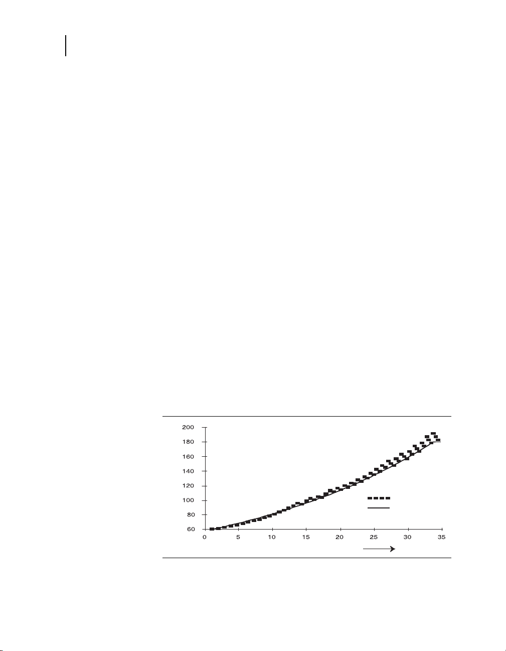
Figure 2-6 shows the rate response curve for an elderly patient.
Figure 2-7 shows the rate response curve for a pediatric patient.
For a given rate response curve (for example, curve 7), both
patients achieve their Upper Sensor Rates for the same level of
sustained sensor-detected activity, but the rates are quite
different. Use the programmed rate limits and the Rate Response
Curve to match the rate prescription to the patient’s needs.
InSync III Model 8042 Device Reference Guide

Programming rate and rate response parameters
USR
LR
Pacing Rate
(ppm)
Increasing Activity
USR
LR
Pacing Rate (ppm)
Increasing Activity
Rate Responsive Pacing
Figure 2-5. Rate Response Curve Setting for An Elderly Patient
Figure 2-6. Rate Response Curve Setting for a Pediatric Patient
49
How Activity Acceleration and Deceleration Influence Rate
Activity Acceleration and Activity Deceleration times control how
rapidly the pacing rate changes in response to increased or
decreased physical activity. One programmable Activity
Deceleration setting, “Exercise” provides an extended
deceleration period following prolonged exercise.
InSync III Model 8042 Device Reference Guide

50
Time (Minutes)
Rate Range
Lower
Rate
Upper
Sensor
Rate
Activity Acceleration
Programmable Settings
15 Seconds
30 Seconds
60 Seconds
Chapter 2
Rate Responsive Pacing
Activity Acceleration
Activity Acceleration time is the time required to achieve
approximately 90% of the difference between the current rate and
a higher steady-state rate consistent with the current level of
activity. Figure 2-7 shows a graphic representation of the
acceleration curves at the onset of strenuous exercise.
Figure 2-7. Activity Acceleration Curves
Activity Deceleration
Activity Deceleration time is the time required to achieve
approximately 90% of the difference between the current rate and
a lower steady-state rate consistent with the current level of
activity. Figure 2-8 shows a graphic representation of the
deceleration curves at an abrupt cessation of strenuous exercise.
InSync III Model 8042 Device Reference Guide

Programming rate and rate response parameters
Time (Minutes)
Rate Range
Lower
Rate
Upper
Sensor
Rate
Activity Deceleration
Programmable Settings
2.5 Minutes
5 Minutes
10 Minutes
Figure 2-8. Activity Deceleration Curves
51
Rate Responsive Pacing
Exercise Deceleration Option
Programming Activity Deceleration to “Exercise” extends the rate
slowing period following an exercise episode to provide up to
20 minutes of rate deceleration. The device uses activity sensor
data to detect periods of vigorous, prolonged exercise. At the end
of such an exercise period, the device uses a longer deceleration
curve for the central portion of the programmed rate range. The
actual deceleration rate is determined dynamically based on the
intensity and duration of exercise and the new level of activity.
Figure 2-9 shows the composite deceleration curve that applies
after the abrupt cessation of sustained exercise.
InSync III Model 8042 Device Reference Guide

52
Time (Minutes)
Rate Range
Lower
Rate
Upper
Sensor
Rate
5 Minute Deceleration Curve
Begins Exercise Deceleration
Ends Exercise
Deceleration
5 Minute
Deceleration
Curve
Chapter 2
Rate Responsive Pacing
Figure 2-9. Exercise Deceleration
Typical Rate Response Settings
Nominal rate response parameter settings are adequate for many
patients: Activity Threshold = Medium/Low, Rate Response
Curve = 7, Acceleration = 30 seconds, Deceleration = Exercise.
■
For most patients, the device may be programmed to operate
at or near the programmed Lower Rate when the patient is
lying, sitting, or standing. If the patient has an elevated pacing
rate at rest, Activity Threshold may need to be programmed to
a higher setting.
■
InSync III Model 8042 Device Reference Guide
When the patient is walking at a moderate pace, the pacing
rate will typically reach 90 ppm to 105 ppm. During more
vigorous exercise, the pacing rate will typically reach the
Upper Sensor Rate. If the patient has minimal rate response
during exercise, Activity Threshold may need to be
programmed to a lower setting.
■
A simple programmer-assisted exercise test may be used to
tailor rate response settings to a patient’s needs.
■
The Rate Histogram diagnostic may be used to validate
programmed rate response settings.

Programming rate and rate response parameters
Using the Exercise Test to Adjusting Rate Response
A programmer-assisted Exercise test can be use to evaluate the
patient’s rate response and to allow for programming of the
following rate response parameters from the Exercise test results
screen.
■
The Desired Rate, Lower Rate, and Upper Sensor Rate
parameters (the Rate Response Curve parameter is adjusted
automatically based on changes to these parameter values).
■
Activity Acceleration and Deceleration parameters.
Refer to the InSync III Model 8042 Device Reference Guide for
instructions on using the Exercise test.
53
Rate Responsive Pacing
InSync III Model 8042 Device Reference Guide


AV intervals, refractory and blanking
periods
AV Intervals 56
Rate Adaptive AV 58
Blanking Periods 62
Refractory Periods 64
High Rate Atrial Tracking 75
3
3

56
PAV
Interval
PAV
Interval
PAV
PAV
Chapter 3
AV Intervals
AV Intervals
Paced AV Interval (PAV)
In dual chamber modes, the AV intervals determine the time
between the occurrence of an atrial event and the scheduled
delivery of stimuli to the ventricles. Separate AV intervals for
paced and sensed atrial events are available. The lengths of these
intervals may be fixed or programmed to be rate adaptive.
Note: With biventricular pacing, event timing that involves a
ventricular pace is always based on the first ventricular stimulus.
The timing diagrams in this chapter depict only the first stimulus of
a biventricular pacing output.
PAV follows an atrial pace in the DDDR, DDD, DDIR, DDI, DVIR,
DVI, DOOR, and DOO modes. The PAV interval may differ from
the programmed value due to one of the following operations:
■
Rate Adaptive AV
■
Ventricular Safety Pacing
■
Non-Competitive Atrial Pacing
Figure 3-1. Example of PAV Interval Operation
InSync III Model 8042 Device Reference Guide

Sensed AV Interval (SAV)
SAV
Interval
SAV
Interval
SAV SAV
SAV follows an atrial sensed event in atrial synchronous pacing
modes (DDDR, DDD, and VDD). The SAV interval duration may
differ from the programmed value due to one of the following:
■
Rate Adaptive AV
■
Automatic PVARP
■
Upper Tracking Rate
At fast intrinsic atrial rates, the SAV extends as needed to avoid
violation of the programmed Upper Tracking Rate or the total atrial
refractory period.
Figure 3-2. Example of SAV Interval Operation
AV intervals, refractory and blanking periods
AV Intervals
57
InSync III Model 8042 Device Reference Guide

58
Chapter 3
Rate Adaptive AV
Selecting PAV and SAV
Rate Adaptive AV
Overview
When you program AV intervals, the general hemodynamic goal is
to assure that, to the extent possible, left-atrial systole is
completed before left-ventricular systole begins. To achieve this,
the AV interval durations may be adjusted independently of each
other.
■
To accommodate the difference in interatrial conduction times,
the SAV usually should be programmed to a shorter duration
than the PAV, typically 30 to 50 ms shorter. If an SAV greater
than the PAV is selected, the programmer notes that this is not
usual, but the selected values may be programmed if clinically
warranted.
■
When the SAV is longer than the PAV, a V pace following an
atrial sense will always occur after the full SAV, even when the
sensor-indicated rate or Lower Rate interval expires first.
In the normal heart, AV conduction times tend to shorten as the
heart rate increases and lengthen as the heart rate decreases.
The Rate Adaptive AV (RAAV) feature, available in the DDDR,
DDD, DDIR, DVIR, DOOR, and VDD modes, mimics this
physiologic response. When RAAV is programmed On, the device
shortens AV intervals for atrial rates within a programmed rate
range. This feature provides increased opportunity for atrial
sensing, as follows:
■
Shortened SAV intervals increase the tracking range at fast
atrial rates by shortening the total atrial refractory period
(TARP) and increasing the 2:1 block rate. Refer to “Total Atrial
Refractory Period (TARP)” on page 68 and “High Rate Atrial
Tracking” on page 75 for more information.
■
Shortened PAV intervals lengthen the atrial sensing window of
the VA interval at higher sensor-driven rates.
Note: RAAV will not shorten AV intervals to less than 30 ms.
InSync III Model 8042 Device Reference Guide

Programming Rate Adaptive AV
For RAAV operation, the SAV and PAV are programmed (as
applicable) to the values desired for low rates. Additional
programmable parameters control how AV intervals are adjusted
at higher rates:
Start Rate – RAAV operation of shortening SAV and PAV intervals
begins at this rate.
Stop Rate – The shortest SAV and PAV occur at this rate and at
all higher rates, up to the upper rate limits.
A minimum value for either SAV or PAV is selectable, depending
on the pacing mode:
Minimum Sensed AV Interval – The shortest allowable SAV,
used at or above the Stop Rate is programmed in the DDDR, DDD,
and VDD modes.
Minimum Paced AV Interval – The shortest allowable PAV, used
at or above the Stop Rate is programmed in the DDIR, DVIR, and
DOOR modes. In the DDDR mode, the value is automatically
determined by the programmer.
AV intervals, refractory and blanking periods
Rate Adaptive AV
59
Figure 3-4 shows how the SAV and PAV intervals are linearly
shortened as the rate increases from below the Start Rate to
above the Stop Rate.
InSync III Model 8042 Device Reference Guide
60
Atrial Rate Increasing by 2 bpm/beat
Time (Seconds)
Rate (bpm)
MAR
Intrinsic Rate
Chapter 3
Rate Adaptive AV
Rate Adaptive AV Operation
Shortening of the AV interval(s) occurs when the appropriate rate
exceeds the programmed Start Rate, as follows:
SAV – The mean atrial rate determines SAV adjustments.
Because of how the mean atrial rate is calculated:
■
SAV adjustments will lag during rapid increases or decreases
in intrinsic atrial rates.
■
The SAV is not adjusted for isolated events (PACs).
■
AS–AP or AR–AP intervals may affect the SAV value since
these intervals are not used in the mean atrial rate calculation.
PAV – The sensor-indicated rate determines PAV adjustments.
The approximate difference between programmed SAV and PAV
is maintained as the SAV and PAV intervals are adjusted.
About Mean Atrial Rate
Mean atrial rate (MAR) is a running average of the atrial rate that
is used by the Rate Adaptive AV and automatic PVARP features.
The average uses all A–A intervals (except AS-AP or AR-AP
intervals). In order to respond quickly to rapidly increasing atrial
rates, the average gives preference to shorter A-A intervals over
longer intervals when calculating the MAR. Figure 3-3 shows how
the MAR tracks an increasing intrinsic atrial rate.
Figure 3-3. Increasing Mean Atrial Rate
InSync III Model 8042 Device Reference Guide

AV intervals, refractory and blanking periods
Rate (ppm)
AV Interval (ms)
Parameters:
Start Rate = 80 ppm Programmed PAV = 200 ms Programmed SAV = 170 ms
Stop Rate = 150 ppm Minimum PAV = 100 ms Minimum SAV = 70 ms
Start Rate Stop Rate
Programmed PAV
Programmed SAV
Minimum SAV
Minimum PAV
R
a
t
e
A
d
a
p
t
i
v
e
P
A
V
R
a
t
e
A
d
a
p
t
i
v
e
S
A
V
Figure 3-4. Rate Adaptive AV Operation (DDDR Mode)
61
Rate Adaptive AV
Rate Adaptive AV Operation in DDDR and DDD Modes
The DDDR and DDD modes use both the PAV and SAV intervals:
■
DDDR Mode – Both the SAV and PAV may be adjusted.
■
DDD Mode – SAV may be adjusted. The PAV is not adjusted
unless mode switch is on. Mode switching to the nonatrial
tracking DDIR mode requires the PAV.
InSync III Model 8042 Device Reference Guide

62
Chapter 3
Blanking Periods
Blanking Periods
Blanking periods disable sensing for a programmable or
nonprogrammable interval. Signals that are blanked may originate
in either chamber or from outside sources such as noise from
muscle movement.
Figure 3-5. Example of Dual Chamber Blanking Operation
Note: Black bars indicate blanking periods.
1 Nonprogrammable Atrial Blanking
2 Programmable Post-Ventricular Atrial Blanking
3 Programmable Ventricular Blanking
4 Nonprogrammable Ventricular Blanking
Nonprogrammable Blanking Periods
Immediately following a sensed or paced event in either chamber,
sensing for that chamber is blanked for a nonprogrammable
period that may vary from 50 to 100 ms. The actual duration of the
blanking period is determined dynamically by the device, based on
the strength and duration of the signal. Dynamic blanking prevents
sensing the same signal twice, while minimizing total blanking
time.
InSync III Model 8042 Device Reference Guide

Post-Ventricular Atrial Blanking
The programmable Post-Ventricular Atrial Blanking (PVAB)
period, used in the DDDR, DDD, DDIR, DDI, VDD, VDIR, and VDI
modes, prevents sensing of ventricular paced events or far-field
R waves on the atrial lead. Any ventricular event (paced or
sensed) starts the PVAB, which is also the first portion of the
Post-Ventricular Atrial Refractory period (PVARP). PVAB is limited
to values equal to or less than the programmed PVARP, except in
the VDIR and VDI modes in which PVARP does not apply.
Note: PVAB is set to a value less than or equal to PVARP.
Ventricular Blanking
The programmable Ventricular Blanking period, which follows an
atrial pacing stimulus in the DDDR, DDD, DDIR, DDI, DVIR, and
DVI modes, prevents ventricular inhibition or ventricular safety
pacing due to sensing of the atrial stimulus on the ventricular lead
(crosstalk). The Ventricular Blanking period also applies to the
ADIR and ADI modes to prevent sensing of the atrial stimulation.
■
Long blanking periods (36 ms or greater) increase the
possibility of unsensed ventricular events.
■
Long blanking periods used in conjunction with long PAV
intervals (250 ms or greater) may result in pacing into the
T wave when intrinsic ventricular events are blanked and not
sensed. PAV values (200 ms or less) should reduce the
possibility of T wave pacing.
AV intervals, refractory and blanking periods
Blanking Periods
63
Single Chamber Atrial Blanking
The programmable single chamber atrial blanking period, used in
the AAIR, ADIR, AAI, ADI, and AAT mode, prevents sensing of
far-field R waves. It is started by a paced, sensed, or refractory
sensed atrial event.
Note: Atrial Blanking must be programmed at least 50 ms less
than the Atrial Refractory Period.
InSync III Model 8042 Device Reference Guide

64
Chapter 3
Refractory Periods
Refractory Periods
Overview
A refractory period is an interval during which an intrinsic event
sensed on a particular lead channel cannot start certain timing
intervals. Each refractory period begins with a blanking period,
during which no sensing occurs. During the unblanked portion of
a refractory period, sensing occurs, but sensed events may not
directly affect timing operations. Refractory periods are intended
to prevent certain timing intervals from being started by
inappropriate signals such as retrograde P waves, far-field
R waves, or electrical noise.
Though they may not start timing intervals, refractory sensed
events are monitored by the device, and they affect the operation
of PVC Response, Mode Switch, Rate Adaptive AV operation,
automatic PVARP, Non-Competitive Atrial Pacing, and other
features for which the periodicity or number of sensed events are
pertinent. Refractory sensed events are included on Marker
Channel recordings.
Post-Ventricular Atrial Refractory Period
The Post-Ventricular Atrial Refractory Period (PVARP) follows a
paced, sensed, or refractory sensed ventricular event in the
DDDR, DDD, DDIR, DDI, and VDD modes. It is intended primarily
to prevent the sensing of retrograde P waves that might promote
Pacemaker-Mediated Tachycardias (PMTs) in atrial tracking
modes. In the DDIR and DDI modes, PVARP prevents atrial
inhibition from retrograde P waves.
InSync III Model 8042 Device Reference Guide

AV intervals, refractory and blanking periods
PVARP
Refractory Periods
The first portion of the PVARP is the programmable
Post-Ventricular Atrial Blanking period (PVAB). During the
remainder of the PVARP, intrinsic atrial events may be sensed as
refractory sensed events (AR) and identified on Marker Channel
recordings, but they do not affect stimulus timing.
■
In the DDDR, DDD, and VDD modes, an SAV is not started.
■
In the DDDR, DDD, DDIR, and DDI modes, the scheduled
atrial pace is not inhibited.
Figure 3-6. Example of PVARP Operation
65
The duration of the PVARP may be selected as follows:
■
The PVARP should be programmed to a value greater than
the patient’s ventriculoatrial (VA) retrograde time when
retrograde conduction is present.
■
Excessively long PVARPs may induce 2:1 block at high
intrinsic rates in atrial tracking modes (DDDR, DDD, and
VDD).
■
To reduce the 2:1 block point, PVARP can be set to “auto.”
When it is programmed to “auto,” the device varies the PVARP
based on whether the operating mode is a tracking or
nontracking mode.
InSync III Model 8042 Device Reference Guide

66
Chapter 3
Refractory Periods
Auto PVARP (Tracking Modes)
When the device is operating in a tracking mode (DDDR, DDD, or
VDD), Auto PVARP varies based on the mean atrial rate (see
“About Mean Atrial Rate” on page 60). To facilitate tracking of fast
atrial rates, Auto PVARP maintains a 2:1 block rate at least
30 ppm greater than the mean atrial rate. The device
automatically adjusts the PVARP to produce a Total Atrial
Refractory Period equal to the target 2:1 block rate. Refer to “Total
Atrial Refractory Period (TARP)” on page 68.
For these modes, Auto PVARP is intended to do the following:
■
Provide a higher 2:1 block rate by shortening the PVARP at
higher tracking rates.
■
Protect against PMTs at lower rates by providing a longer
PVARP.
The calculated 2:1 block rate has the following limits:
■
The minimum 2:1 block rate is 100 ppm for Minimum PVARP
settings of 150 to 250 ms. If Minimum PVARP is greater than
250 ms, the minimum 2:1 block rate will be less than 100 ppm.
■
The maximum 2:1 block rate is the Upper Tracking Rate plus
35 ppm. If Mode Switch is enabled, the maximum 2:1 block
rate is the Detect Rate (only if this rate is less than the Upper
Tracking Rate plus 35 ppm).
Figure 3-7 shows how Auto PVARP is equal to Minimum PVARP
when tracking occurs at the Upper Tracking Rate and how it is
adjusted to a longer value at the Lower Rate.
InSync III Model 8042 Device Reference Guide

AV intervals, refractory and blanking periods
Upper
Tracking
Rate
Lower
Rate
SAV PVARP SAV PVARP
Minimum
PVARP
480 ms
Figure 3-7. Auto PVARP Operation (DDDR Mode)
67
Refractory Periods
Auto PVARP (Nontracking Modes)
When the device is operating in a nontracking mode (DDIR or
DDI), Auto PVARP varies with the sensor-indicated rate in the
DDIR mode or the lower rate in the DDI mode. The device
automatically adjusts PVARP to maintain a 300-ms sensing
window.
For these modes, Auto PVARP is intended to do the following:
■
Promote AV synchrony by preventing inhibition of atrial pacing
by an atrial sense early in the VA interval.
■
Reduce the likelihood of competitive atrial pacing at high
sensor-indicated rates.
Figure 3-8 shows how Auto PVARP is equal to PVAB when pacing
occurs at the Upper Sensor Rate and how it is adjusted to a longer
value as pacing slows to the Lower Rate.
InSync III Model 8042 Device Reference Guide

68
Upper
Sensor
Rate
Lower
Rate
PAV PVARP PAV PVARP
Chapter 3
Refractory Periods
Figure 3-8. Auto PVARP Operation (DDIR Mode)
Total Atrial Refractory Period (TARP)
In dual chamber modes that sense in the atrium, the Total Atrial
Refractory Period (TARP) is the sum of two intervals, as follows:
AV Inte r val – The AV interval begins with an atrial event and ends
with a ventricular event. The first portion is a nonprogrammable
blanking period. Its complete duration is determined as follows:
■
In the DDDR, DDD, and VDD modes, the PAV or SAV interval
is the AV interval.
■
In the DDIR and DDI modes, the AV interval starts with the first
atrial sensed event in the VA interval or with an atrial pacing
stimulus; it ends when the PAV expires, even when ventricular
pacing is inhibited.
Post-Ventricular Atrial Refractory Period (PVARP) – For
information, refer to“Post-Ventricular Atrial Refractory Period” on
page 64.
InSync III Model 8042 Device Reference Guide

Figure 3-9. Total Atrial Refractory Period)
TARP TARP
SAV + PVARP
PVARP PVARPSAVSAV
During atrial tracking, TARP = SAV + PVARP, and its duration
determines the rate at which 2:1 block occurs. Refer to “High Rate
Atrial Tracking” on page 75 for more information.
Ventricular Refractory Period
AV intervals, refractory and blanking periods
Refractory Periods
69
The programmable Ventricular Refractory Period (VRP) follows
paced, sensed, and refractory sensed ventricular events
(including PVCs) in all dual chamber and ventricular modes that
sense in the ventricle. The VRP is intended to prevent sensing of
the T wave or a PVC. The first portion of the VRP is a
nonprogrammable blanking period. A ventricular refractory
sensed event affects device timing as follows:
■
Ventricular blanking and refractory periods restart in all
modes.
■
In the DDDR, DDD, and VDD modes, the upper tracking rate
interval, PVARP, and PVAB also restart.
■
In the VVIR and VDIR modes, the upper sensor rate interval
restarts.
Note: In dual chamber modes, the VRP should be programmed
shorter than the PVARP.
InSync III Model 8042 Device Reference Guide

70
VRP
Chapter 3
Refractory Periods
Figure 3-10. Example of Ventricular Refractory Period Operation)
In dual chamber modes, a ventricular refractory sensed event
does not affect a scheduled sensor-driven or lower rate atrial
output. Thus, a sensor-driven atrial output pulse will initiate a PAV
with a ventricular output pulse following, unless inhibited.
Interventricular Refractory Period
The programmable Interventricular Refractory Period can be used
to address double counting of ventricular events from the same
cardiac depolarization, which can occur when the device is
configured to sense on both ventricular leads or to pace on one
ventricular lead and sense on the other.
Double counting restarts the PVARP timer. This can impact the
ability to maintain 1:1 tracking. An atrial event falling within the
extended PVARP results in a refractory sense (AR) that cannot be
tracked (Figure 3-11).
InSync III Model 8042 Device Reference Guide

Figure 3-11. Interventricular Refractory Period
Interventricular
Refractory Period Off
Interventricular
Refractory Period On
Interventricular Refractory Period
AV intervals, refractory and blanking periods
Refractory Periods
71
A ventricular sense occurring within the Interventricular Refractory
Period (following a ventricular pace or non-refractory sense) does
not reset the timing intervals and allows the next sinus beat to be
tracked.
Refer to “Programming Interventricular Refractory Period” on
page 83 for additional information.
InSync III Model 8042 Device Reference Guide

72
Chapter 3
Refractory Periods
Atrial Refractory Period (Single Chamber)
The programmable Atrial Refractory Period (ARP) follows paced,
sensed, and refractory sensed atrial events. The ARP is used in
the AAIR, ADIR, AAI, ADI, and AAT modes. It is intended to
prevent inhibition due to far-field R wave sensing. The first portion
of the ARP is a programmable blanking period. The ARP should
be programmed to a value long enough (150 ms or greater) to
prevent far-field R wave sensing but short enough to ensure atrial
sensing up to the programmed Upper Sensor Rate.
Noise Reversion
When sensing occurs during the Atrial Refractory Period (ARP) or
Ventricular Refractory Period (VRP), the refractory period (and its
blanking period) are restarted. The operation associated with
continuous refractory sensing in the ARP or VRP is called noise
reversion. Multiple restarts of the ARP or VRP (continuous noise
reversion) do not inhibit scheduled pacing. Device behavior during
continuous noise reversion is as follows:
■
Pacing occurs at the sensor-indicated rate for all rate
responsive modes (except VVIR and VDIR).
■
Pacing occurs at the programmed Lower Rate for all
non-rate-responsive modes (including VVIR and VDIR).
On the ECG, noise reversion may be difficult to distinguish from
loss of sensing, but Marker Channel recordings will show
refractory sense markers when noise reversion occurs.
Note: Atrial sensing during the PVARP, or refractory period
following an atrial paced or sensed event in the DDDR, DDD,
DDIR, DDI, or VDD modes does not restart the refractory period.
An atrial refractory sensed event, however, will start a short
blanking period of 50 to 100 ms depending on the signal strength
and duration of the atrial event.
InSync III Model 8042 Device Reference Guide

AV intervals, refractory and blanking periods
Sensor-Indicated Interval
Parameters:
Lower Rate = 60 ppm (1000 ms) Upper Sensor Rate = 120 ppm (500 ms)
PAV Interval = 200 ms Ventricular Refractory Period = 240 ms
PVARP = 300 ms PVAB = 200 ms
Sensor Sensor Sensor
Lower Rate
Parameters:
Lower Rate = 60 ppm (1000 ms) Upper Sensor Rate = 120 ppm (500 ms)
Ventricular Refractory Period = 240 ms
Sensor Sensor
Refractory Periods
Figure 3-12. Example of Noise Reversion in DDDR at Sensor-Indicated Rate
Figure 3-13. Example of Noise Reversion in VVIR at Lower Rate
73
InSync III Model 8042 Device Reference Guide

74
Chapter 3
Refractory Periods
Preventing Noise Sensing
Noise reversion may be caused by electromagnetic interference
(EMI), myopotentials, excessively high output settings, or low
sensitivity settings. When it has been identified, noise reversion
usually can be reduced or eliminated by one of the following
actions:
Spontaneous PVARP Extension
The programmed PVARP duration and the automatic PVARP may
be overridden by the PVC Response and PMT Intervention
features, as follows:
■
Reprogram sensitivity to a less sensitive setting (higher
numerical value).
■
Reprogram sensing polarity to bipolar polarity (if available).
■
Reduce the amplitude and/or pulse width in the same or
opposite chamber.
■
Remove patient from EMI environment.
■
When the PVC Response feature is programmed On and a
device-defined PVC occurs, the PVARP is forced to 400 ms
for one cycle if a lesser value is in effect.
■
When PMT Intervention is programmed On and a
device-defined PMT is detected, the PVARP is forced to
400 ms for one cycle after the ninth paced ventricular event of
the PMT.
Refer to “PMT Intervention” on page 98 and “PVC Response” on
page 100 for further details on the PMT Intervention and PVC
Response features and their interactions with PVARP.
InSync III Model 8042 Device Reference Guide

High Rate Atrial Tracking
Overview
In the DDDR, DDD, and VDD modes, the fastest atrial rate the
device can track is determined by the total atrial refractory period
(TARP), which is the sum of the SAV and the PVARP. Device
behavior at high atrial rates in these modes is determined by the
relationship between the TARP and the interval corresponding to
the Upper Tracking Rate. In the DDDR mode, the interval
corresponding to the Upper Sensor Rate also must be considered.
2:1 Block
When the intrinsic atrial interval is shorter than the TARP, some
atrial events will fall in the PVARP and not be tracked. At the rate
where this first occurs, ventricular tracking occurs only on
alternate beats, and 2:1 block ensues. In the DDD and VDD
modes, the ventricular pacing rate drops precipitously.
■
When automatic PVARP is selected, the 2:1 block rate may
occur at a higher rate during activity due to shortening of the
PVARP, thus increasing atrial tracking.
■
When Rate Adaptive AV operation is selected, the SAV
shortens at high atrial rates, shortening the TARP and raising
the 2:1 block rate.
■
When the 2:1 block rate is less than the Upper Tracking Rate,
the Upper Tracking Rate cannot be achieved.
■
In the DDDR mode, pacing at the sensor-indicated rate may
prevent a precipitous rate drop at the 2:1 block point when
activity is present.
■
For patients with a documented propensity for prolonged or
sustained atrial fibrillation or flutter, the clinician can select
Upper Tracking Rate, SAV, and PVARP values that induce
2:1 block at a desired rate (2:1 block rate = 60,000/TARP).
Alternatives for controlling rates in these patients include use
of the Mode Switch feature and DDIR mode pacing.
■
In the DDDR mode, atrial competition may occur if Upper
Sensor Rate exceeds the 2:1 block rate.
AV intervals, refractory and blanking periods
High Rate Atrial Tracking
75
InSync III Model 8042 Device Reference Guide

76
Upper Tracking
Rate Interval
Parameters:
Sensor-Indicated Rate = 90 ppm (667 ms) PVARP = 300 ms
PAV Interval = 230 ms Upper Tracking Rate = 100 ppm (600 ms)
SAV Interval = 200 ms
Sensor
Upper Tracking
Rate Interval
Upper Tracking
Rate Interval
SAV
Interval
Chapter 3
High Rate Atrial Tracking
Pacemaker Wenckebach
When the 2:1 block rate exceeds the programmed Upper Tracking
Rate, pacemaker Wenckebach may occur. When the intrinsic rate
exceeds the Upper Tracking Rate, a pacing stimulus at the
expiration of the SAV would violate the upper tracking rate. The
device therefore extends the SAV until the upper tracking rate
interval expires. Subsequent SAVs require greater extension, until
an atrial event falls in the PVARP and is not tracked.
■
In the DDDR, DDD, and VDD modes, the result normally is a
fixed ratio between atrial and ventricular rates (3:2, 4:3, and so
forth).
■
In the DDDR mode, the pacemaker Wenckebach rate may be
smoothed by sensor-driven ventricular pacing, thereby
overriding the fixed ratio.
The following example shows how pacemaker Wenckebach
operation occurs in the DDDR, DDD, or VDD modes.
Figure 3-14. Example of Pacemaker Wenckebach Operation
InSync III Model 8042 Device Reference Guide

AV intervals, refractory and blanking periods
High Rate Operation in the DDDR Mode
Table 3-1 summarizes how the total atrial refractory period
(TARP), the Upper Tracking Rate (UTR) interval, and the Upper
Sensor Rate (USR) interval may interact at high atrial rates in the
DDDR mode.
Tab le 3-1 . Upper Rates Interaction With TARP
Relationship
Between TARP and
Upper Rate
Intervals
TARP > both USR
and UTR intervals
Wenckebach
High Rate Atrial Tracking
Achieve
Before 2:1
Block
no no yes
Upper
Tracking
Rate
77
Potential
Atrial
Competition
a
USR interval > TARP
no no no
> UTR interval
USR interval > UTR
yes yes no
interval > TARP
UTR interval > both
yes yes yes
USR interval and
TARP
a
Unless the Non-Competitive Atrial Pacing is On, see “Non-Competitive Atrial
Pacing” on page 96.
a
InSync III Model 8042 Device Reference Guide


Configuring polarity, output, and
Polarity and Lead Monitor 80
Ventricular Pacing Configuration 86
Output and Sensitivity 90
sensing
4
4

80
Chapter 4
Polarity and Lead Monitor
Polarity and Lead Monitor
The InSync III device provides independently programmable
pacing polarity and sensing polarity for each ventricle (RV and LV)
and the atrium. Each output channel also has its own Lead
Monitor, which enables the implanted device to monitor lead
integrity. If programmed to do so, Lead Monitor can adapt bipolar
pacing and sensing to a unipolar configuration if it detects a lead
problem.
Pacing Polarity
The Pace Polarity parameter sets the polarity configuration for
delivery of pacing stimuli in each chamber. Programmable Pace
Polarity options are as follows:
Chamber Pace Polarity Options
Atrium Bipolar, Unipolar
Right Ventricle (RV) Bipolar, Unipolar
Left Ventricle (LV) Bipolar, LVtip/RVring, Unipolar
Bipolar – With this configuration, which is applicable only to
bipolar leads, the lead tip is the active electrode; the lead ring is
the common electrode. Bipolar pacing is less likely to produce
muscle stimulation, but it produces smaller pacing artifacts on the
patient’s ECG. Bipolar is a compatible pacing polarity for patient’s
who also have an implanted defibrillator (ICD).
Unipolar – With this configuration, the lead tip is the active
electrode; the noninsulated device case is the common electrode.
Unipolar pacing produces larger pacing artifacts that aid ECG
interpretation. However, it is more likely to cause muscle
stimulation at the device implantation site, especially at high
pacing amplitudes. Unipolar pacing is contraindicated in patients
with an implanted ICD.
LVtip/RVring – This configuration applies only to pacing in the left
ventricle. The LV lead tip is the active electrode; the RV lead ring
is the common electrode. The LVtip/RVring option is intended for
use with a unipolar LV lead to provide a bipolar pacing pathway for
compatibility with an implanted ICD or to prevent muscle
stimulation at the device implantation site (pocket).
InSync III Model 8042 Device Reference Guide

Configuring polarity, output, and sensing
Polarity and Lead Monitor
Note: When LV Pace Polarity is set to LVtip/RVring and the left
ventricle is the first chamber paced, capture of the right ventricle
by the RV ring electrode may occur, especially at high outputs.
This may result in biventricular pacing with no V-V delay. To
restore sequential biventricular pacing with the left ventricle paced
first, program LV output to a setting below the RV ring capture
threshold or program an alternate setting for LV Pace Polarity.
Pacing with a Shared Electrode and Short V-V Delay
When RV Pace Polarity is set to Bipolar, and LV Pace Polarity is
set to LVtip/RVring, the RV lead ring serves as a shared common
electrode for both RV and LV outputs. If a V-V Delay of 20 ms or
less is used for biventricular pacing with this polarity configuration,
polarization at the RV ring electrode can reduce amplitude of the
ventricular stimuli by up to 0.5 V.
This interaction should be considered during measurement of
ventricular stimulation thresholds and can be mitigated by
increasing ventricular amplitude by 0.5 V. Amplitude reduction is
not present with V-V Delay settings greater than 20 ms or with
other Pace Polarity settings.
81
Muscle Stimulation with Unipolar Pacing
Under certain circumstances such as high output settings,
device-induced muscle stimulation may occur at the pocket site.
Such muscle stimulation may be minimized or eliminated by
programming pulse width or amplitude to a lower setting.
Bipolar or LVtip/RVring Pacing Polarity Confirmation
Before the programmer allows you to program from Unipolar to
Bipolar or LVtip/RVring pacing, it verifies the presence of a bipolar
current path by testing the impedance for each lead.
■
If the impedance is between 200 ohms and the programmed
Lead Monitor maximum impedance level (limit is 4000 ohms),
a bipolar path is assumed to be present.
■
If the impedance is outside this range, a unipolar path is
assumed to be present. The programmer warns that the test
failed, and pacing polarity remains set to unipolar. This
interlock feature may be overridden to force lead pacing
polarity to bipolar.
InSync III Model 8042 Device Reference Guide

82
Chapter 4
Polarity and Lead Monitor
Sensing Polarity
Warning: Overriding the bipolar verification prompt with Bipolar or
LVtip/RVring polarity when a bipolar path does not exist results in
no pacing output.
The Sense Polarity parameter sets the polarity configuration for
sensing the atrial and the ventricular depolarization signals. You
can configure ventricular sensing to use the right ventricle or both
ventricles.
Chamber Sense Polarity Options
Atrium Bipolar, Unipolar
Ventricle RV Bipolar, RV Unipolar, RVtip/LVtip
Warning: Do not program RVtip/LVtip option for Sense Polarity in
pacemaker-dependent patients until stability of the left ventricular
lead is confirmed. Dislodgement of this lead to a position where
the lead senses atrial activity can result in ventricular inhibition.
Using RV (right ventricular) sensing in pacemaker-dependent
patients for the first 6 months after device implantation will reduce
the potential for this to occur.
Bipolar, RV Bipolar – With these configurations, which are
applicable only to bipolar leads, the lead tip and the lead ring
electrodes are the poles of the sensing circuit. Because bipolar
sensing is more localized, it reduces the likelihood of sensing
myopotentials and electromagnetic interference. This may permit
programming sensitivity to a more sensitive setting.
Unipolar, RV Unipolar – With the unipolar configurations, the
lead tip and the noninsulated device case are the sensing
electrodes. Unipolar sensing may allow sensing of smaller intrinsic
signals than does bipolar sensing and therefore can be selected
when intrinsic cardiac signals are difficult to detect. However,
oversensing due to myopotentials is more common with unipolar
sensing than with bipolar sensing.
InSync III Model 8042 Device Reference Guide

Configuring polarity, output, and sensing
Polarity and Lead Monitor
RVtip/LVtip – This configuration uses the tip of the RV lead and
the tip of the LV lead as the two sensing electrodes to provide
sensing in both ventricles. This configuration allows the device to
sense the first ventricle to depolarize, which may have timing
advantages, particularly when the Ventricular Sense Response
feature is used. Note the following points regarding use of the
RVtip/LVtip configuration:
■
Stability of the left ventricular lead should be confirmed before
using the RVtip/LVtip configuration.
■
The RV Sensitivity parameter adjusts sensitivity when the
RVtip/LVtip configuration is enabled.
■
The RV EGM Telemetry Mode displays the composite EGM of
both ventricles. The LV EGM, Dual VEGM, and A+LV EGM
Telemetry Mode options are not available with the RVtip/LVtip
configuration.
■
With the RVtip/LVtip sensing configuration, a timing difference
between the depolarization of the right and the left ventricles
can result in double sensing during a single contraction unless
the Interventricular Refractory Period is programmed as
described next.
83
Programming Interventricular Refractory Period
When RVtip/LVtip is chosen as the ventricular sensing polarity
configuration, the Interventricular Refractory Period should be
used to prevent sensing of the second depolarization signal when
the right and left ventricles do not depolarize simultaneously.
A ventricular sense occurring within the Interventricular Refractory
Period (following a ventricular pace or non-refractory sense) does
not reset timing intervals (see “Interventricular Refractory Period”
on page 70).
By setting up the programmer live rhythm display to show an EGM
trace of ventricular sensing in both chambers, you can use the
Freeze function to measure the delay between depolarizations.
InSync III Model 8042 Device Reference Guide

84
Chapter 4
Polarity and Lead Monitor
Figure 4-1. RV and LV Depolarization Delay
Interventricular Refractory Period should be programmed to an
interval that is at least 30 ms greater than the measured delay
between chamber depolarizations. A programming restriction
requires that the selected value for Interventricular Refractory
Period be at least 60 ms shorter than the Ventricular Refractory
Period.
During a patient follow-up session, the ventricular Heart Rate
Histogram diagnostic printed report can be used to verify the
effectiveness of the programmed Interventricular Refractory
Period. The report lists the number of VS-VR sequences counted
since the last patient session.
The count for “VS-VR Short” indicates the number of VR senses
falling within the Interventricular Refractory Period. Conversely,
the count for “VS-VR Long” indicates the number of VR senses
falling outside the Interventricular Refractory Period. A high count
for the VS-VR Long sequence may indicate the need for a longer
Interventricular Refractory Period.
Bipolar Sensing Polarity Confirmation
Before the programmer allows you to program from unipolar to
bipolar sensing, it verifies the presence of a bipolar lead by testing
the impedance for each lead.
■
If bipolar lead impedance is between 200 ohms and the
programmed Lead Monitor maximum impedance level (limit is
4000 ohms), a bipolar lead is assumed to be present.
InSync III Model 8042 Device Reference Guide

Lead Monitor
Configuring polarity, output, and sensing
Polarity and Lead Monitor
■
If bipolar lead impedance is outside this range, a unipolar lead
is assumed to be present. The programmer warns that the test
failed, and sensing polarity remains set to unipolar. This
interlock feature may be overridden and lead sensing polarity
forced to bipolar.
The Lead Monitor feature measures lead impedances during the
life of the device. When programmed to do so, Lead Monitor
causes the device to switch from bipolar pacing and sensing to
unipolar pacing and sensing in the monitored bipolar lead if the
measured impedance goes outside the limits of a preset range.
Caution: A notification that Lead Monitor has detected an
out-of-range lead impedance is an indication that lead integrity
should be thoroughly investigated.
How Lead Monitoring Works
The Lead Monitor feature monitors lead integrity in paced
chambers (as defined by the pacing mode and ventricular pacing
configuration) by measuring lead impedance every 3 hours.
Impedance must fall within the programmed impedance range for
a stable lead. The acceptable impedance range is from 200 ohms
to a programmable value between 1000 and 4000 ohms.
85
Each paced chamber has its own set of Lead Monitor parameters.
These parameters and the programmable options are listed
below.
Parameter Options
Polarity Switch Monitor/Switch, Monitor Only, Off
Notify If < (lead impedance is
less than 200 ohms)
Notify If > (lead impedance is
greater than __ ohms)
(preset, not programmable)
1000, 2000, 3000, 4000 ohms
Polarity Switch – Sets Lead Monitor to operate according to one
of these options:
Monitor/Switch - Monitor lead impedance and switch pacing and
sensing polarity from Bipolar or LVtip/RVring to Unipolar when the
device detects an out-of-range impedance.
InSync III Model 8042 Device Reference Guide

86
Chapter 4
Ventricular Pacing Configuration
Monitor Only - Monitor lead impedance but do not switch polarity
when an out-of-range impedance is detected.
Off - Turns off Lead Monitor in the respective chamber.
Notify If < (less than) – Nonprogrammable minimum value for
acceptable atrial and ventricular bipolar lead impedance. Fixed at
200 ohms.
Notify If > (greater than) – Programmable maximum limit for
acceptable bipolar lead impedance for the monitored lead.
If Lead Monitor switches a lead from bipolar to unipolar polarity
(Monitor/Switch option) or just detects an out-of range impedance
value (Monitor Only option), the device issues a lead warning that
appears on the programmer screen at the next interrogation.
Do not program the Lead Monitor Ventricular or Atrial Polarity
Switch to Monitor/Switch for patients with an implantable
defibrillator because the monitor automatically reprograms the
selected lead(s) to unipolar polarity if an out-of-range lead is
detected.
Ventricular Pacing Configuration
In addition to providing independently programmable output
parameters (amplitude, pulse width, and polarity) for each
ventricular chamber, the InSync III device has the following
programmable parameters that allow you to further configure
delivery of ventricular stimuli.
■
Ventricular Pacing
■
First Chamber Paced
■
V-V Pace De lay
■
Ventricular Sense Response
■
Maximum Response Rate
InSync III Model 8042 Device Reference Guide

Ventricular Pacing
Parameters:
PAV = 150 ms
SAV = 120 ms
Sense Polarity = RV Bipolar
Ventricular Pacing = RV+LV
First Chamber Paced = LV
V-V Pace Delay = 20 ms
SAV V-V Pace Delay PAV
To provide cardiac resynchronization, the Ventricular Pacing
parameter must be programmed to the RV+LV setting. Pacing
stimuli are delivered to both ventricles. Initiation and delivery of a
pacing stimulus to one chamber results in delivery of a pacing
stimulus to the other chamber after a 4 ms delay, unless a longer
V-V Pace Delay has been programmed.
Note: The RV and LV settings for this parameter allow for
independent assessment of RV and LV lead performance.
First Chamber Paced
When biventricular (RV+LV) pacing is enabled, this parameter
sets the first chamber to be paced as RV or LV. The delay interval
between delivery of a pace to the first and second chamber is
programmable (see “V-V Pace Delay” on page 87).
V-V Pace Delay
When biventricular (RV+LV) pacing is enabled, the V-V Pace
Delay parameter sets the amount of time that elapses between
delivery of a stimulus to the first ventricle paced and delivery of a
stimulus to the other ventricle. The V-V Pace Delay, which has a
minimum of 4 ms, can be programmed up to 80 ms.
Configuring polarity, output, and sensing
Ventricular Pacing Configuration
87
Figure 4-2. Example V-V Pace Delay
InSync III Model 8042 Device Reference Guide

88
Programmed V-V Pace Delay
Ventricular Sense Response Initiated at 8 ms
Maximum Response Rate Interval
V-V Pace Delay is 4 ms
Chapter 4
Ventricular Pacing Configuration
Ventricular Sense Response
Note: If Ventricular Safety Pacing or Ventricular Sense Response
is enabled, paces generated in response to a ventricular sense will
be delivered at the minimum (4 ms) V-V delay.
Note: Also see “Pacing with a Shared Electrode and Short V-V
Delay” on page 81.
Ventricular Sense Response is intended to provide cardiac
resynchronization in the presence of ventricular sensing by
allowing a ventricular sense to initiate a ventricular or biventricular
pace. The programmable settings for Ventricular Sense Response
are Off and Pace.
When Ventricular Sense Response is enabled in a dual chamber
mode, a ventricular sense that occurs during the PAV interval
initiates an immediate ventricular or biventricular pace. A
ventricular sense that is preceded by a non-refractory atrial sense
will initiate an immediate ventricular or biventricular pace if the
pace does not exceed the programmed Maximum Response
Rate.
InSync III Model 8042 Device Reference Guide
Figure 4-3. Ventricular Sense Response

When Ventricular Sense Response is enabled in a single chamber
mode, a ventricular sense will initiate an immediate ventricular or
biventricular pace if the pace does not exceed the programmed
Maximum Response Rate.
The initiated paces are delivered according to the programmed
Ventricular Pacing setting (RV, or RV+LV). If biventricular pacing
(RV+LV) is enabled, the biventricular stimuli are delivered at the
minimum (4 ms) V-V pace delay.
A count of the ventricular sense (VS) events that initiated a
Ventricular Sense Response or a Ventricular Safety Pace is
displayed with the Ventricular Rate Histogram (see page 128).
Maximum Response Rate
The programmable Maximum Response Rate applies when
Ventricular Sense Response is enabled. This parameter
determines the maximum rate at which ventricular or biventricular
paces can be initiated in response to ventricular senses.
Maximum Response Rate can be programmed from 90 to
150 ppm. Maximum Response Rate applies to initiated responses
in single chamber modes and to initiated responses during the
SAV interval in dual chamber modes.
Configuring polarity, output, and sensing
Ventricular Pacing Configuration
89
With Ventricular Sense Response enabled, an initiated pace can
occur only if the time elapsed since the last ventricular event
represents a rate equal to or less than the programmed Maximum
Response Rate.
InSync III Model 8042 Device Reference Guide

90
Chapter 4
Output and Sensitivity
Output and Sensitivity
Output (Amplitude and Pulse Width)
The InSync III device allows you to program separate amplitude
and pulse width settings for each of the ventricular output
channels and the atrial channel. Pacing output settings should be
based on stimulation thresholds measured in each of the paced
chambers. Stimulation energy should be high enough to ensure
reliable capture, but not so high as to unnecessarily deplete the
device battery.
Determining Stimulation Thresholds at Implant
At the time of device implantation, an external analyzer, such as a
Medtronic Pacing System Analyzer or Lead Analysis Device,
should be used to determine the stimulation threshold values for
each pacing lead. Refer to the analyzer manual for detailed
instructions.
Verifying Stimulation Thresholds at Follow-up
Medtronic 9790 series programmers provide both automatic and
manual threshold tests for measuring the stimulation threshold of
each lead at the time of patient follow-up. Stimulation threshold
resolution is based on the programmable increments of amplitude
and pulse width. A Strength-Duration test constructs a
strength-duration graph that shows amplitude and pulse width
safety margins.
Selecting Output Parameters
Generally, to provide an adequate safety margin, select a pacing
voltage twice the chronic stimulation threshold voltage for a given
pulse width. For most patients, pacing outputs are the major
contributor to battery depletion.
To maximize battery longevity, select the lowest amplitude and
pulse width settings that provide at least a 2:1 voltage safety
margin. A greater safety margin may be advisable during the lead
maturation process.
Note: Also see “Pacing with a Shared Electrode and Short V-V
Delay” on page 81.
InSync III Model 8042 Device Reference Guide

Sensitivity
Configuring polarity, output, and sensing
Output and Sensitivity
Note: An amplitude of 7.5 V substantially reduces expected
battery longevity. These amplitudes should be limited to
short-term uses such as “Emergency” settings and
electrophysiologic studies or long-term uses for specific
indications such as exit block.
Note: High output pacing at 7.5 V may affect ECG or intracardiac
electrogram (EGM) waveform quality and potentially cause
crosstalk or self-inhibition.
For Additional Information
Refer to “Estimated Longevity Projections” on page 178 for further
information on device longevity under various pacing scenarios.
Refer to “Programmable Modes and Parameters” on page 192 for
further information on amplitude and pulse width parameter
settings. Refer to “Crosstalk and Self-Inhibition” on page 207 for
further information on crosstalk or self-inhibition.
Sensitivity determines the minimum intracardiac signal that the
device can detect when intrinsic atrial or ventricular events occur.
Sensitivity settings should be based on the measured amplitude of
the depolarization signal detected in each chamber at the time of
device implantation and at follow-up. Intracardiac signal
amplitudes can decrease during the lead maturation process.
91
Determining Sensing Signal Amplitudes at Implant
At implant, use a Medtronic Pacing System Analyzer or Lead
Analysis Device to determine sensing threshold values for the
device. Refer to the respective manual for detailed instructions.
Before connecting a bipolar lead, measure the sensing potentials
in the unipolar and the bipolar configurations. Adequate
intracardiac signal should be present in both configurations to
ensure proper sensing in either.
InSync III Model 8042 Device Reference Guide

92
Chapter 4
Output and Sensitivity
Verifying Sensitivity Settings at Follow-up
The 9790 series programmer provides an automatic Sensing Test
that allows the clinician to verify a patient’s sensitivity settings at
follow-up. This test can determine the approximate amplitude of P
or R waves detected by the atrial lead or the ventricular leads,
respectively. The test displays the sensitivity setting just above
and below the point at which P-wave or R-wave sensing occurs.
Selecting Sensitivity Settings
Atrial and ventricular sensitivity are independently programmable.
In general, a 2:1 to 3:1 sensitivity safety margin (threshold
sensitivity value divided by 2 or 3) is adequate for newly implanted
or chronic leads. For example, an atrial sensitivity of 1.0 mV
should be satisfactory for intrinsic atrial signals between 2.0 mV
and 3.0 mV.
■
Always perform a sensing test for each applicable channel to
determine the appropriate sensitivity setting.
■
Excessively sensitive (low) settings can cause some or all of
the following problems:
– oversensing due to electromagnetic interference (EMI),
myopotentials, T waves, or crosstalk
– undersensing due to overloading of the sensing circuit
– noise reversion operation
■
Atrial Sensitivity with Bipolar sensing and Lead Monitor set to
Off or Monitor Only allows 0.18 mV, 0.25 mV, and 0.35 mV
atrial sensitivity settings. To prevent oversensing of muscle
noise or electromagnetic interference, unipolar sensing is
limited to values no less than 0.5 mV.
■
Ventricular Sensitivity at 1.0 mV or 1.4 mV with wide atrial
pulse widths or high atrial amplitudes may result in ventricular
safety pacing (if the Ventricular Safety Pacing feature is On)
with some lead systems at high sensor-driven pacing rates.
Reprogramming Ventricular Sensitivity to a less sensitive
setting (higher numerical value) is one option under such
circumstances. Other options include programming a longer
ventricular blanking period.
InSync III Model 8042 Device Reference Guide

Configuring polarity, output, and sensing
Output and Sensitivity
Effects of Myopotentials During Unipolar Pacing
Myopotentials can affect device operation when sensing polarity is
unipolar, especially with atrial sensitivity settings of 0.5 through
1.0 mV and ventricular sensitivity settings of 1.0 and 1.4 mV.
Myopotentials sensed on the atrial channel outside the total atrial
refractory period (SAV + PVARP) start sensed AV intervals in the
DDDR, DDD, and VDD modes.
Continuous myopotentials cause reversion to asynchronous
operation when sensed in the refractory period:
■
on the ventricular channel at intervals less than the ventricular
refractory period in the DDDR, DDD, DDIR, DDI, DVIR, DVI,
VDD, VVIR, VDIR, VVI, VDI, and VVT modes,
■
on the atrial channel at intervals less than the atrial refractory
period in the AAIR, ADIR, AAI, ADI, and AAT modes.
In the VVIR and VDIR modes, the resulting asynchronous pacing
occurs at the Lower Rate, otherwise such asynchronous pacing
occurs at the sensor-indicated rate for rate response modes or the
Lower Rate for non-rate response modes.
For Further Information
93
Refer to “Noise Reversion” on page 72 for a description of noise
reversion operation. Refer to “Atrial Lead” on page 193 and “Right
(RV) and Left (LV) Ventricular Leads” on page 193 for tables that
provide sensitivity parameter settings. In the Pacing System
Analyzer or Lead Analysis Device manual, refer to sensitivity
threshold test procedures.
InSync III Model 8042 Device Reference Guide


Special therapy options
Non-Competitive Atrial Pacing 96
PMT Intervention 98
PVC Response 100
Ventricular Safety Pacing 103
Sleep Function 105
5
5

96
Pace atrium safely,
no capture
Relative refractory
period, atrial pace
may induce atrial
tachycardia
Pace atrium
safely, capture
Chapter 5
Non-Competitive Atrial Pacing
Non-Competitive Atrial Pacing
Overview
Non-Competitive Atrial Pacing (NCAP) is intended to prevent
triggering of atrial tachycardias by an atrial pacing stimulus that
falls within the atrium’s relative refractory period. This feature may
be programmed On or Off in the DDDR and DDD modes.
Figure 5-1. The Relative Refractory Period of the Atrium
How NCAP Affects Atrial Timing
InSync III Model 8042 Device Reference Guide
When NCAP is programmed On, a refractory sensed atrial event
falling in the PVARP starts a 300-ms NCAP period, during which
no atrial pacing may occur:
■
■
■
If a sensor-driven or lower rate pacing stimulus is scheduled
to occur during the NCAP period, the VA interval is extended
until the NCAP period expires.
If no pacing stimulus is scheduled to occur during the NCAP
period, timing is unaffected; pacing occurs at the end of the VA
interval unless inhibited.
An atrial refractory sensed event occurring during the NCAP
period starts a new NCAP period.

How NCAP Affects Ventricular Timing
Sensor-Indicated
Interval
Sensor-Indicated
Interval
NCAP
300 ms
Sensor SensorNCAP
Parameters:
Sensor-Indicated Rate = 120 ppm (500 ms)
PAV Interval = 150 ms
PVARP Interval = 230 ms
Post-Ventricular Atrial Blanking (PVAB) = 180 ms
Ventricular Refractory Period = 230 ms
30 ms
When an atrial pacing stimulus is delayed by the NCAP operation,
the device attempts to maintain a stable ventricular rate by
shortening the PAV interval that follows. It will not, however,
shorten the PAV interval to less than 30 ms. When a relatively high
Lower Rate and long PVARP are programmed, NCAP operation
may result in ventricular pacing slightly below the Lower Rate.
Figure 5-2. Non-Competitive Atrial Pacing Operation
Special therapy options
Non-Competitive Atrial Pacing
1
97
1
With biventricular pacing, event timing that involves a ventricular pace is always
based on the first ventricular stimulus. The timing diagrams in this chapter depict
only the first stimulus of a biventricular pacing output.
InSync III Model 8042 Device Reference Guide

98
Chapter 5
PMT Intervention
NCAP Availability
For Further Information
PMT Intervention
The Non-Competitive Atrial Pacing feature may be programmed
On or Off only in the DDDR and DDD modes. Its availability is also
dependent on the following:
■
When Mode Switch is programmed On, NCAP operations are
temporarily disabled if the pacing mode switches to the
non-atrial tracking mode. The NCAP feature is reenabled
upon return to the atrial tracking mode.
■
Even when NCAP is programmed Off, the NCAP operation is
invoked automatically for cycles on which PMT Intervention or
PVC Response operations occur.
Refer to “Programming Mode Switch” on page 35, “PMT
Intervention” on page 98, and “PVC Response” on page 100 for
more information on these therapy features.
Overview
A Pacemaker-Mediated Tachycardia (PMT) may occur when
retrograde P waves (due to a loss of AV synchrony) are sensed
and tracked in an atrial tracking mode. PMT Intervention provides
an automatic way for the device to detect and interrupt
device-defined PMTs. This programmable On or Off feature is
available in the DDDR, DDD, and VDD modes.
Caution: Even with the feature turned On, PMTs may still require
clinical intervention such as device reprogramming, magnet
application, drug therapy, or lead evaluation.
InSync III Model 8042 Device Reference Guide
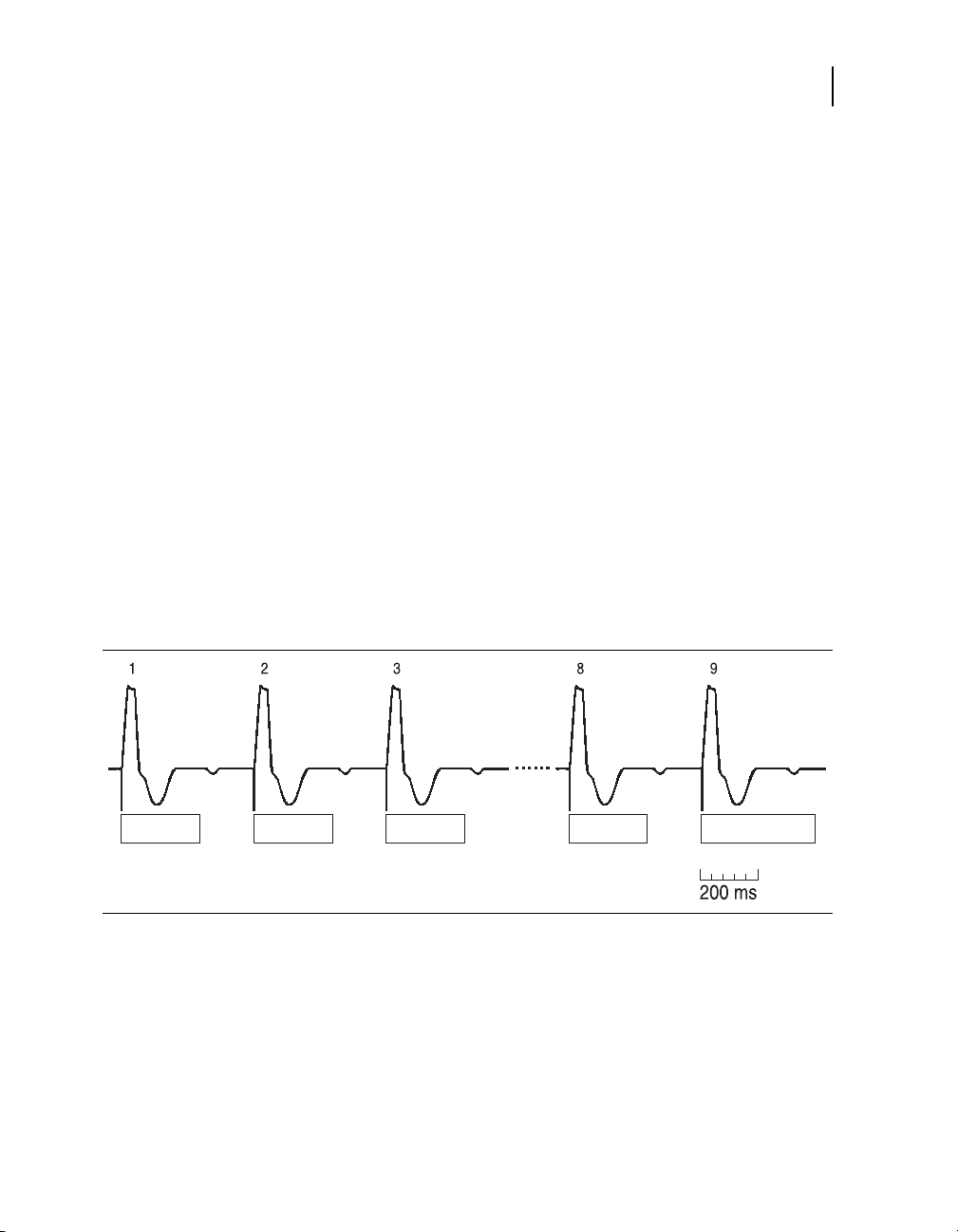
How the Device Defines PMT
PVARP PVARP PVARP PVARP PVARP = 400 ms
Parameter:
PVARP = 280 ms
The device assumes that a PMT may be present when it detects
a ninth ventricular pace following eight consecutive VA intervals
that meet all of the following conditions:
■
Duration less than 400 ms
■
Start with a ventricular paced event
■
End with an atrial sensed event
PMT Therapy Intervention
When a device-defined PMT is detected, the device intervenes,
forcing a 400-ms PVARP after the ninth paced ventricular event
(see Figure 5-3). If a PMT is indeed in progress, the extended
PVARP ensures that the next atrial sensed event within 400 ms
will be refractory. By interrupting atrial tracking for one cycle, the
PMT may be stopped.
Note: A sinus tachycardia could cause PMT therapy intervention,
resulting in a single P wave falling in the PVARP and, therefore,
not being tracked by the device.
Special therapy options
PMT Intervention
99
Figure 5-3. PMT Intervention
Automatic Therapy Suspension
After therapy intervention, PMT Intervention is automatically
suspended for 90 seconds. This prevents unnecessary
intervention in the presence of fast intrinsic atrial rates.
InSync III Model 8042 Device Reference Guide

100
Chapter 5
PVC Response
Interactions with Other Features
The PMT Intervention feature interacts with other device features
in the following ways:
■
■
Patient Intervention for PMT
When Auto PVARP is active, the patient can often terminate a
PMT simply by resting quietly, causing the sensor-indicated rate to
drop and the PVARP to extend. When PVARP becomes longer
than the retrograde time, the PMT may terminate.
For Further Information
Refer to “Non-Competitive Atrial Pacing” on page 96 and
“Programming Mode Switch” on page 35 for more information on
these therapies.
Non-Competitive Atrial Pacing (NCAP) is automatically
enabled for one cycle after the ninth ventricular pace of a
device-defined PMT episode. The NCAP feature may shorten
the ensuing PAV to maintain a stable ventricular rate.
If Mode Switch is On, PMT Intervention is temporarily disabled
if the device switches to the non-atrial tracking mode. It is
reenabled upon return to the atrial tracking mode.
PVC Response
Overview
The Premature Ventricular Contraction (PVC) response feature is
available in the DDDR, DDD, DDIR, DDI, and VDD modes. The
feature, which is programmable On or Off, is intended for the
following purposes:
DDDR, DDD, and VDD modes – PVC Response is intended to
prevent tracking of retrograde P waves generated by PVCs. This
response helps prevent initiation of pacemaker-mediated
tachycardia.
InSync III Model 8042 Device Reference Guide
 Loading...