


®
/C/TEMP/198676001C_view.pdf
INSYNC
Device Model 8040
Programmer Software Model 9980
Device Programming Guide
Caution: Federal law (USA) restricts this device to sale by or on
the order of a physician.


InSync® Model 8040 Device
Programming Guide
A Guide to using the
9790 series programmer
and 9980 software with
the InSync device
4

The following terms are trademarks of Medtronic.
InSync, marker Channel, and Medtronic
5

About This Programming Guide
Information about the InSync Model 8040 device is presented in
two separate guides: the InSync Model 8040 Device Programming
Guide (this guide) and the InSync Model 8040 Device Reference
Guide.
This programming guide provides instructions for using a 9790
series programmer with the InSync Model 8040 device. Sections
describe the applicable programming and follow-up functions
and present step-by-step procedures for using these functions.
Information is organized into the 9 chapters and one appendix:
Chapter 1 – Introductory information
Chapter 2 – General procedures
Chapter 3 – Starting and ending a patient session
Chapter 4 – Retrieving system data
Chapter 5 – Displaying and printing the patient’s ECG and EGM
Chapter 6 – Programming the device parameters
Chapter 7 – Determining and evaluating parameter settings
Chapter 8 – Using the diagnostic data recording function
Chapter 9 – Programmer setup options, such as setting the time
and date
Appendix A – Programmable parameters, values, and
programming restrictions
The InSync Model 8040 Device Reference Guide provides
information about the functions and operation of the device. The
reference guide is supplemental to the Product Information
Manual packaged with the InSync device.
InSync® Model 8040 Device Programming Guide iii
6

iv InSync® Model 8040 Device Programming Guide
7

Table of Contents
About This Programming Guide iii
1. Using the Programmer with an InSync Device
When to Use this Manual 1-2
Conventions Used in this Manual 1-3
General Warnings and Precautions 1-4
Display Screen Format and Interactive Features 1-7
A Guide to Using the Menu and Command Buttons 1-11
2. Procedures to Know Before You Begin
Using the Programming Head 2-2
Programming Emergency Parameters 2-5
Interrogating the InSync Device 2-6
Canceling Effects of the Programming Head Magnet 2-8
Printing Reports During a Patient Session 2-9
Automatic Printing with the Printer Trace Mode 2-12
Printing Reports After a Session Has Ended 2-13
Transferring Session Data to a Diskette 2-14
Using the HELP Options 2-17
3. Starting and Ending a Patient Session
Before You Begin 3-2
Turning the Programmer ON 3-3
Starting a Patient Session 3-4
Selecting the Desired Function 3-6
Ending a Patient Session 3-8
4. Retrieving System Data
Displaying Present Parameter Settings 4-2
Displaying a Status Summary 4-6
Displaying Battery and Lead Information 4-11
Displaying a Graph of Recorded Diagnostic Data 4-14
5. Displaying and Printing the Patient’s ECG and EGM
Printing the Patient’s ECG and EGM 5-2
Displaying the Patient’s ECG and EGM 5-5
InSync® Model 8040 Device Programming Guide v
8

Freezing the ECG Trace 5-11
Displaying a Marker Channel Diagram 5-15
6. Programming the Pacing Parameters
Programming Pacing Parameters 6-2
Programming Additional Parameters 6-12
7. Determining and Evaluating Parameter Settings
Measuring Stimulation Thresholds 7-2
Determining a Setting for Sensitivity 7-21
Determining Rate Response Parameter Settings 7-28
Programming Temporary Parameter Values 7-38
Measuring Rate and AV Interval 7-41
8. Collecting and Retrieving Diagnostic Data
About the Diagnostics Function 8-2
Types of Data You Can Record 8-4
Recording Data From a Non-Paced Chamber 8-17
Programmable Parameter Options 8-19
About the Setup Options 8-22
Programming the Device to Record Data 8-24
Displaying a Graph of the Recorded Data 8-29
Printing the Diagnostic Data 8-32
Clearing Recorded Data From the Device 8-33
9. Programmer Setup Options
Setting the Time and Date 9-2
Connecting an External Recorder or Monitor 9-4
Using the CALIBRATE Option 9-5
Improving the Detection of Pacing Artifacts 9-7
A. Appendix A - Parameter Values and Restrictions
Programmable Modes and Parameters A-2
Programming Requirements and Restrictions A-6
Temporary Modes and Parameters A-9
I. Index
vi InSync® Model 8040 Device Programming Guide
9

Using the Programmer
General Desciption
with an InSync Device 1
This chapter introduces you to using your 9790 series
programmer with the InSync device.
When to Use this Manual 1-2
Conventions Used in this
Manual 1-3
General Warnings and
Precautions 1-4
Display Screen Format and
Interactive Features 1-7
A Guide to Using the Menu and
Command Buttons 1-11
1
10
InSync® Model 8040 Device Programming Guide 1-1

When to Use this Manual
Installation of the 9980 software adds the InSync Model 8040
device to the programming and follow-up capabilities of your
9790 series programmer. Several manuals now cover the use of
your programmer, each covering a specific set of implantable
device models.
InSync Model 8040 device – If you select this device model, refer
to this manual for instructions on using the programmer.
Other device models – If you select a device model other than the
InSync Model 8040 device, refer to the appropriate programming
guide supplied with the software application for that device. The
front cover of each programming guide lists the device models
covered in that guide.
For detailed information on setting up the 9790 programmer, refer
to the instruction manual, Programmer Description and Setup,
supplied with the programmer.
1-2 InSync® Model 8040 Device Programming Guide
11

Conventions Used in this Manual
This manual uses the following text format conventions in the
instructions for using the programmer.
[INTERROGATE] Boldface small capitals within brackets denote
THRESHOLD TEST Boldface capitals without brackets denote a
1., 2., 3 Boldface numbers at the left column margin
➤ This symbol identifies a single instructional
■ This symbol is used as a bullet indicating
an on-screen button.
selectable screen option other than a button.
identify instructional steps.
statement.
itemized statements or paragraphs.
12
InSync® Model 8040 Device Programming Guide 1-3

General Warnings and Precautions
These warnings and precautions apply in general to using a 9790
series programmer.
Warnings
Using the Programmer
Programming should be done only after careful study of the
device technical manual and the applicable portions of this
manual and after careful determination of appropriate parameter
settings. Improper use of the programmer could result in
erroneous or inadvertent programming and improper operation
of the telemetry and measurement functions.
The 9790 series programmer must be used only for programming
Medtronic devices listed as applicable units for the software being
used. Direct stimulation via energy coupling may occur if the
programmer is used on other implanted devices. This
programmer is not compatible with programmable devices of
other manufacturers.
Implantable Defibrillator
Some patients may also require therapy from an implantable
defibrillator.
■
Only bipolar pacing should be used with these patients. In
some cases, pacing in the unipolar configuration may cause
the defibrillator to either deliver inappropriate therapy or to
withhold appropriate therapy.
■
Programming Lead Monitor with the optional polarity switch
is contraindicated for patients with an implanted defibrillator.
When an out-of-range lead is detected, the monitor
automatically reprograms selected leads to unipolar polarity.
Pacing in the unipolar configuration may either cause the
defibrillator to provoke inappropriate therapy or to withhold
appropriate therapy.
1-4 InSync® Model 8040 Device Programming Guide
13

■
Programming the Transtelephonic Monitor On is
contraindicated for patients with an implanted defibrillator.
When the monitor is programmed On, the pacing polarity is
temporarily set to unipolar when the magnet is applied over
the implanted device. Pacing in the unipolar configuration
may either cause the defibrillator to provoke inappropriate
therapy or to withhold appropriate therapy.
Precautions
High Rate Stimulation
Before and after the use of high-rate stimulation, the clinician
should interrogate the implanted device to determine the battery
status and elective replacement indicator (ERI) condition.
High-rate stimulation over several years, or with the battery
partially depleted, may trigger the ERI prematurely.
Loss of Programmer Power
If power to the programmer is unexpectedly lost, lifting the
programming head from over the patient’s device cancels any
temporary parameters or functions in effect and restores the
device to its permanently programmed state.
14
Unresponsive Screen
In the unlikely event the programmer display screen becomes
unresponsive or “locked,” turn the programmer off, wait
5 seconds, then turn the programmer on. Normal programmer
operation should resume. Following successful completion of the
self test, reselect the device model to continue with the
application.
Programming Head
Failure to correctly align the programming head over the InSync
device could result in failure of a programming transmission and
failure to receive telemetry. The programming head should not be
positioned over an implanted device during electrocautery or
InSync® Model 8040 Device Programming Guide 1-5

defibrillation procedures. Refer to “Using the Programming
Head” in Chapter 2 for specific information about using the
programming head.
1-6 InSync® Model 8040 Device Programming Guide
15

Display Screen Format and Interactive Features
This section describes the appearance of the programmer display
screen and the scheme for selecting the various functions or tasks
you wish to accomplish during the patient session.
Display Screen Example
Below is an example of the screen format you will see when you
use the programmer with an InSync device.
Menu Buttons
Device ID
Screen Title
ECG Display
Function Display Area
16
Message Box
Command Buttons
Figure 1-1. Features of the Display Screen
The main elements of this screen format are as follows:
Menu Buttons – The menu buttons, which appear across the
top of each screen, provide direct access to the applicable
programmer functions.
Device ID – Displays the selected device family name and model
number.
InSync® Model 8040 Device Programming Guide 1-7

Screen Title – Title of the current screen generally appears in this
location.
ECG Display – This box continuously displays a low-resolution
trace of the patient’s ECG.
Function Display Area – This area of the screen changes
according to the selected function. It displays the data, buttons,
and options that apply to the selected function.
Message Box – The message box continuously displays
procedural prompts and status messages including warnings
and precautions, when appropriate. It is important to read the
information presented in the Message Box whenever you are operating
the programmer.
Command Buttons – Location of the [
MAGNET], [INTERROGATE], and [INTERROGATE ALL] buttons is
the same on all function screens where they apply. The
[
EMERGENCY] programming button appears in this location on all
function screens.
PROGRAM], [CANCEL
Interactive Screen Features
The display screen has interactive features that respond to
application of the touch pen, or stylus, are: 1) on-screen buttons
and 2) options that appear in boldface type. The following are
some examples of buttons and options.
Buttons appear as boldface words or symbols enclosed within a
black rectangular border. Buttons with labels ending in an ellipsis
(...) open a window of additional options.
Button Examples
1-8 InSync® Model 8040 Device Programming Guide
17

Selectable options, which appear in boldface type, include device
model options, parameters, parameter values, and menu options.
Selectable options
appear in boldface
lettering.
Selecting a Button
➤ Without touching the screen, move the tip of the stylus to a
position directly over the button; then press the stylus
against the screen.
If the button is a “locking” button (one that remains selected), the
button label will change to reverse video to indicate that it is
selected.
If a procedure directs you to “press and hold” a button, you must
press the stylus against the button and continue to press for as
long as you want the related operation to continue.
18
Selecting an Option
➤ Without touching the screen, move the tip of the stylus to a
position directly over any part of the boldface option label
(may be a word or number); then press the stylus against the
screen.
InSync® Model 8040 Device Programming Guide 1-9

Audible Signals
Certain events in the operation of the programmer will result in an
audible signal of one or two tones, or “beeps.” These signals are
intended to alert the user to the success or failure of an action.
Single Beep = Success
■
A single beep following an Interrogate command indicates
that the interrogation was successful.
■
A single beep following a Program command indicates that
the programming was confirmed.
Two Beeps = Failure
■
Two beeps following an Interrogate command indicate that
the interrogation was not successful.
■
Two beeps following a Program command indicate that the
programming was not confirmed.
Two Low-Tone Beeps
Two low-tone beeps sound when the selected command cannot be
executed.
Single Short Beep
A short beep that coincides with pressing the
PROGRAM key on the programming head indicates that the
programmer acknowledges the keystroke. If the keystroke is
inappropriate, two low-tone beeps will sound.
1-10 InSync® Model 8040 Device Programming Guide
19
INTERROGATE or

A Guide to Using the Menu and
Command Buttons
Using the Menu Buttons
Except for [END SESSION] and [FREEZE], selecting a menu button
at the top of the screen displays a drop-down menu of related
function options. A check mark (✓) next to a displayed option (see
example below) indicates that option is currently selected.
Menu Buttons
Drop-down Menu
Note: To close the menu without making a selection, “click” the
stylus anywhere on the display screen outside the menu box.
Listed below is a description of the options accessible with each of
the menu buttons. Refer to the listed chapter for the procedure
associated with each option.
20
Retrieving Device System Data – See Chapter 4.
Selecting the [
■
Viewing a summary of interrogated data.
■
Viewing measured real-time values of battery and lead data.
■
Viewing a graph of accumulated diagnostic data.
DATA] menu button displays options for:
InSync® Model 8040 Device Programming Guide 1-11

Displaying the Patient’s ECG and EGM – See Chapter 5.
Selecting the [
TESTS/ECG] menu button displays an option for
viewing and adjusting the patient’s ECG and the EGM and
Marker Channel signals received from the implanted device via
telemetry. The ECG display includes an option for inhibiting the
output of the patient’s device.
Conducting Device System Tests – See Chapter 7.
Selecting the [
■
Measuring stimulation thresholds.
■
Determining a setting for device sensitivity.
■
Determining a setting for Activity Threshold and Rate
TESTS/ECG] menu button also displays options for:
Response.
■
Programming temporary parameter settings.
■
Measuring rate and AV interval.
■
Conducting electrophysiologic studies if 9886A or 9891A
software is installed. Instructions are covered in a supplement
supplied with the software.
Programming Parameter Settings – See Chapter 6.
Selecting the [
PARAMETERS] menu button displays options for:
■
Programming stimulating parameters and viewing present
settings.
■
Accessing additional parameter options including Extended
Telemetry, Transtelephonic Monitor, Serial Number, and
Status Reset.
Setting Up the Diagnostics Function – See Chapter 8.
Selecting the [
for programming the device to record the selected type of
diagnostic data.
Ending the Patient Session – See Chapter 3.
Selecting the [
session and return to the implantable device model selection
screen.
1-12 InSync® Model 8040 Device Programming Guide
21
PARAMETERS] menu button also displays an option
END SESSION] menu button lets you end the patient

Special Options – See Chapters 2 and 9.
Selecting the [
SPECIAL] menu button provides access to the
following options:
■
A Position Head Assist option related to using the
programming head (Chapter 2).
■
A Calibrate option that sends a Marker Channel or EGM
reference signal to an externally connected recorder or
monitor (Chapter 9).
Freezing the ECG Trace – See Chapter 5.
Selecting the [
FREEZE] menu button freezes a 10-second segment
of the patient’s ECG and provides the option for viewing a Marker
Channel diagram if the device is operating in a permanently
programmed triple chamber or VDD mode.
Printing Reports – See Chapter 2.
Selecting the [
PRINT] menu button displays options for printing
the various data reports generated during the patient session.
Viewing Help Information – See Chapter 2.
Selecting the [
HELP] menu button displays options for viewing
information about the currently displayed screen and other
subjects related to using the programmer.
22
Using the Command Buttons
Listed below is a description of each of the command buttons
located at the bottom of the display screen. Refer to the listed
chapter for the procedure associated with using a particular
command button.
InSync® Model 8040 Device Programming Guide 1-13

Programming Emergency Parameters – See Chapter 2.
Selecting the Emergency command overrides any function and
immediately programs the device to a fixed set of permanent
values that provide high output pacing in the VVI mode.
Canceling the Programming Head Magnet – See Chapter 2.
Selecting the Cancel Magnet command cancels the effect of the
programming head magnet and allows the device to operate in its
permanently programmed state while the programming head is
in position. For example, operation of a device permanently
programmed to the DDD mode will change from the DOO
magnet mode to the DDD mode when this command is executed.
Interrogating the Device – See Chapter 2.
Selecting the Interrogate command from a particular function
screen retrieves from the device the data related to that function.
Interrogating All Data – See Chapter 2.
The Interrogate All command retrieves all data (parameter,
battery/lead, and diagnostic) from the device. This button
appears only on the Pacing Parameters screen.
Returning to the Pacing Parameters Screen –
On screens other than the Pacing Parameters screen, this button
appears in place of [
INTERROGATE ALL]. Selecting this button
returns you directly to the Pacing Parameters screen.
Programming Command – (Covered in the procedures).
This command executes a temporary or permanent programming
transmission based on the procedure being conducted. This
button appears only when programming is allowed.
1-14 InSync® Model 8040 Device Programming Guide
23

Procedures to Know
General Desciption
Before You Begin 2
This chapter covers some procedures that you might
use at any point during a patient session. You should
be familiar with these procedures before you begin a
patient session.
Using the Programming
Head 2-2
Programming Emergency
Parameters 2-5
Interrogating the InSync
Device 2-6
Canceling Effects of the
Programming Head Magnet 2-8
Printing Reports During a Patient
Session 2-9
2
24
Automatic Printing with the
Printer Trace Mode 2-12
Printing Reports After a Session
Has Ended 2-13
Transferring Session Data to a
Diskette 2-14
Using the HELP Options 2-17
InSync® Model 8040 Device Programming Guide 2-1

Using the Programming Head
In many of the procedures described in the following chapters,
you will be directed to position the programming head over the
patient’s implanted device.
■
Always position the programming head prior to executing
any command that results in a programming or telemetry
interaction between the programmer and the device.
■
Improper positioning of the programming head could result
in the inability to program the device or to receive telemetry.
Positioning the Programming Head
Caution: Do not position the programming head over an
implanted device during electrocautery or defibrillation
procedures.
For an implanted device:
1. Position the programming head directly against the patient’s
skin with the face of the programming head parallel to the
device.
2. Position the programming head so that the amber light in the
light array on the head goes out and one or more green lights
come on.
3. Move the head to the position that lights the greatest number
of green lights. This is the optimum position.
2-2 InSync® Model 8040 Device Programming Guide
25
Light Array

Note: Device operation returns to its permanently programmed
settings about 2 seconds after you remove the programming head
from its position over the implanted device.
The programmer also has a programming head position indicator
light located near the upper left corner of the screen. This indicator
light goes out when a telemetry link with the device has been
established — or it may change from amber to green — see Using
the POSITION HEAD ASSIST Option below).
Using the POSITION HEAD ASSIST Option
The Position Head Assist function facilitates using the head
position light on the programmer to locate the optimum head
position over the patient’s device. This function is particularly
useful under conditions that adversely affect the communication
link between the programmer and device.
Assist enabled – The programming head position light on the
display panel changes from amber to green when the
programming head is properly positioned.
Assist disabled – The amber position light goes out when the
programming head is positioned.
26
The light array on the programming head operates the same with
or without the Assist function.
Note: When the Assist function is enabled (“Enhanced” option),
continuous interaction between the programmer and device can
cause extraneous artifacts to appear at 250 ms intervals on the
patient’s ECG trace. The programmer automatically filters these
artifacts so they do not appear. Although these artifacts can
obscure pacing artifacts or small details on the ECG trace, they
have no effect on the pacing operation of the device.
The default setting for the Assist function is Enhanced. That is, the
Assist function is already in effect when you start a patient
session. If this function results in extraneous artifacts on other
monitoring devices connected to the patient, you can turn the
Assist function off by selecting the “Normal” option (see next).
InSync® Model 8040 Device Programming Guide 2-3

Procedure for Selecting the Position Head Assist Setting
1. Select [SPECIAL] from the menu buttons at the top of the
screen.
2. Select
POSITION HEAD ASSIST from the options displayed.
3. From the window showing two buttons:
➤ Select [
➤ Or select [
ENHANCED] to enable the Assist function.
NORMAL] to disable the Assist function.
Using PROGRAM / INTERROGATE Keys
The PROGRAM and INTERROGATE keys on the programming head
have the same function as the [
buttons that appear on the display screen. Whenever the
instructions in this manual direct you to select the [
[
INTERROGATE] button on the screen, you can press the
corresponding key on the programming head instead, if it is more
convenient.
INTERROGATE Key
PROGRAM] and [INTERROGATE]
PROGRAM] or
PROGRAM Key
Figure 2-1. PROGRAM and INTERROGATE Keys on the
2-4 InSync® Model 8040 Device Programming Guide
27
Programming Head

Programming Emergency Parameters
The [
]
The Emergency programming command is a safety feature that
overrides all other functions and immediately programs the
device to preset emergency values intended to provide pacing
support under a variety of conditions. This programming cancels
any temporary function in effect and restores magnet mode
operation.
Emergency values are permanent settings that provide higherthan-normal energy output. It is not intended that the device be left at
these settings.
Note: Use of the Emergency command may not be appropriate for
patients who have an implanted defibrillator. Pacing in the
unipolar configuration may cause the defibrillator either to
deliver inappropriate therapy or to withhold appropriate therapy.
Tab le 2-1. Emergency Values
Pacing Mode
Rate
V. Refractory Period
V. Pulse Amplitude
V. Pulse Width
V. Sensitivity
V. Pace Polarity
V. Sense Polarity
Single Chamber Hysteresis
VVI
70 ppm
330 ms
7.5 V
1.5 ms
2.8 mV
Unipolar
Unipolar
Off
EMERGENCY
button appears in th e
lower left corner of all
function screens.
28
To program Emergency parameters:
1. Position the programming head over the device.
2. Select the [
EMERGENCY] button.
*
3. Hold the programming head steady until a confirmation
message appears. If programming is not confirmed, verify
that the programming head is properly positioned and then
reselect [
*
You can press the square red button on the left side of the display panel as an
alternative to the on-screen [EMERGENCY] button.
EMERGENCY].
InSync® Model 8040 Device Programming Guide 2-5

Interrogating the InSync Device
Before the programmer can display any information about the
status of the patient’s device system, you must interrogate the
device. The information you can retrieve by interrogating the
device falls into three categories:
1. Parameter settings
2. Real-time measurements of battery and lead data
3. Diagnostic data
As described below, you can retrieve this information all at once
or separately as it is needed.
The INTERROGATE ALL Function
The Interrogate All feature retrieves all three types of information
for use during the patient session. This feature may be most
helpful at the start of a patient session, but it can be used at
anytime during the session.
Note: The [
Pacing Parameters Screen.
INTERROGATE ALL] button is available only on the
To execute the Interrogate All command:
1. Select the Pacing Parameters screen.
Note: The Pacing Parameters screen is the first screen to
appear following model selection at the start of a patient
session.
2. Position the programming head over the device.
3. Select the [
programming head steady until success of the interrogation
is confirmed.
2-6 InSync® Model 8040 Device Programming Guide
29
INTERROGATE ALL] button. Continue to hold the

Auto Printout – An Interrogate All command automatically
initiates printing of the following data:
1) the present stimulating and diagnostic parameter settings,
2) a data summary report which includes an Event Summary, and
3) Battery/Lead status data.
Accumulated diagnostic data is not included in this printout.
Auto Save – Executing an Interrogate All command
automatically saves the present programmed parameter settings.
From a parameter programming screen, you can view the saved
values applicable to that screen (select the [
or you can recall the values to the screen as pending values for
programming (select the [
then select the [
SAVED VALUES] button).
SAVE/NOMINAL OPTIONS...] button,
SHOW SAVED] button)
The INTERROGATE Function
From most function screens, you can interrogate the device for the
data associated with that screen. Even when you have used the
Interrogate All feature, it may be necessary to perform additional
interrogations to update the programmer as you conduct the
patient session.
30
To execute the Interrogate command:
1. Position the programming head over the device.
2. Select the [
programming head steady until success of the interrogation
is confirmed.
INTERROGATE] button. Continue to hold the
InSync® Model 8040 Device Programming Guide 2-7

Canceling Effects of the Programming
Head Magnet
“Cancel Magnet” is a temporary programming command that
cancels the effect of the programming head magnet. It allows the
device to operate in its permanently programmed mode (such as
the DDD mode) while the programming head is held in position.
The [
CANCEL MAGNET] button appears near the lower right
corner of all function screens except the Battery/Lead screen
described in Chapter 4.
To execute the Cancel Magnet command:
1. While the programming head is positioned over the device,
select the [
2. Watch for the “Magnet cancelled” message.
CANCEL MAGNET] button.
Continue to hold the programming head in place for as long
as you want the magnet canceled. Lifting the programming
head terminates the Cancel Magnet function.
2-8 InSync® Model 8040 Device Programming Guide
31

Printing Reports During a Patient Session
The [PRINT] menu button lets you select and print various reports
of the data generated during a patient session. Most data is
temporarily stored for the duration of the patient session and can
be printed at any time during the patient session. However, some
types of data, particularly graphic data, must be printed while it
is displayed on the screen. All data stored in programmer memory
is cleared when you start a new patient session.
Selecting a Print Option
Selecting a Print option may cause on-screen buttons, except
[
EMERGENCY], to be unresponsive for several seconds while data
is being formatted for printing. (The formatting of Diagnostic
graphs may take about half a minute.) Selecting a Print option
cancels an ECG recording in progress.
To print a report, select the [
the appropriate print option from the drop-down menu. All
possible options will be listed, but only those in bold face type
are selectable. A report cannot be selected until data for that
report has been generated.
Figure 2-2. Options for Printing Reports
InSync® Model 8040 Device Programming Guide 2-9
PRINT] menu button, and then select
32

About the Print Options
Current Screen Report — If data is available, selecting this option
prints the report for the function associated with the presently
displayed screen. For example, selecting this Print option while
the Pacing Parameters screen is displayed results in the printing
of a Parameter Values report. Use this option to print graphic
reports, which are available only while the data is displayed.
These reports include the Diagnostic Graph, Strength-Duration
Curve, Activity Exercise Test results graph, and Marker Channel
Diagram.
Parameter Values – Selecting this option initiates a printout of all
pertinent parameter values presently programmed and confirmed
in the device.
Data Summary – Selecting this option prints a summary of the
interrogated data. Included are the event data accumulated since
the last patient session.
Battery/Lead Data – Selecting this option initiates a printout of
the real-time measurements associated with the Battery/Lead
data function.
Diagnostics Data Table – This option prints the recorded
Diagnostic data in tabular form. This is the same data the
programmer uses to create and display the Diagnostic Graph.
Threshold Results – Selecting this option prints the data
accumulated during a patient session from the use of the
Threshold Test function. The programmer can store up to 32 test
reports for printing during a patient session.
Sensing Results – Selecting this option prints the data
accumulated from the most recent use of the Sensing Test
function.
Activity Thld Results – Selecting this option prints the results of
an Activity Threshold test.
2-10 InSync® Model 8040 Device Programming Guide
33

Activity Exercise Test – While the test results screen is displayed
following an Activity Exercise test, selecting this option will print
the displayed test results, including the test graph. If the test
results screen is not displayed, the printout will not include the
graph. (Selecting Current Screen Report will also print the
displayed test results and graph.)
Measured Values – Prints the most recent parameter values
obtained from using the Measure ECG function.
Waveforms – Available only if the current screen is the Freeze
screen. This option prints a 10-second chart of frozen ECG and
telemetry traces.
Waveform Segment – Available only if the current screen is the
Freeze screen. This option initiates a printout of only that portion
of the 10-second frozen traces selected with the on-screen calipers.
Full Report – Prints the data accumulated for printing during the
patient session. Reports included in this printout (if the data is
available) are Parameter Values, Data Summary, Battery/Lead
Data, Threshold Results, Sensing Results, Activity Threshold and
Exercise Test results, and Measured Values. This printout does not
include data, such as waveforms or graphs, which can only be
printed while the respective screen is displayed.
34
Tr a ce . .. – Selecting this option displays two buttons that let you
turn the printer “Trace” mode on or off. The following section
describes the printer Trace mode.
InSync® Model 8040 Device Programming Guide 2-11

Automatic Printing with the Printer Trace Mode
To turn the printer Trace mode ON or OFF:
1. Select TRACE... from the Print menu options (see Figure 2-2).
2. From the Trace window, select [
MODE OFF] as desired.
3. Select [
EXIT] to close the window.
TRACE MODE ON] or [TRACE
Turning the Trace Mode On
Turning the Trace mode on causes the printer to automatically
print information as it is generated during a patient session. The
use of such commands as Program, Interrogate, Cancel Magnet,
Emergency, or Measure ECG are documented on the printout if
confirmation of the command execution is received. The
parameters and values included in a programming, interrogation,
or measurement are printed.
Graphic information such as a Diagnostic report is not printed by
the Trace mode. Using the Trace mode does not affect the option
to print specific reports manually.
During the printing of a real-time ECG recording, the Trace mode
does not function. However, data generated while the
programmer is printing frozen waveforms will be saved and
printed when the frozen waveform printout has completed.
Turning the Trace mode off
Turning the Trace mode off disables this automatic printing
feature. Printing will occur only when you select a specific Print
option.
2-12 InSync® Model 8040 Device Programming Guide
35

Printing Reports After a Session Has Ended
Caution: When you end a patient session you will be prompted to
print the data reports generated during the session or transfer
these reports to a computer diskette. Data accumulated during the
patient session is not saved and is lost if you choose not to print or
transfer these reports when prompted.
Procedure
Ending a patient session displays the Print/Transfer Reports popup window shown in Figure 2-3. This window provides the
option to print the data reports accumulated during the session.
36
Figure 2-3. Print/Transfer Reports Pop-up Window
To print the accumulated reports:
➤ Select the [PRINT REPORTS] button in the Print/Transfer
Reports window shown in Figure 2-3.
To delete the reports and proceed to the Select Model
screen:
➤ Select the [CONTINUE] button.
InSync® Model 8040 Device Programming Guide 2-13

Transferring Session Data to a Diskette
Caution: When you end a patient session you will be prompted to
print the data reports generated during the session or transfer
these reports to a computer diskette. Data accumulated during the
patient session is not saved and is lost if you choose not to print or
transfer these reports when prompted.
Procedure
Ending a patient session displays the Print/Transfer Reports popup window shown in Figure 2-4. This window provides the
option to transfer the data reports accumulated during the session
to a computer diskette.
Figure 2-4. Print/Transfer Reports Pop-up Window
To transfer the data reports to a diskette:
1. From the options displayed, select the [TRANSFER REPORTS
TO DISK] button. This displays the window shown below.
2-14 InSync® Model 8040 Device Programming Guide
37

The “Patient ID,” which will be used in a printed header
identifying the data reports, defaults to the device serial
number.
2. To enter a different patient identifier, select each character of
the desired ID from the on-screen keyboard. Select the
[←
DELETE] button to delete an entered character.
Up to six characters of the patient ID will be used in the name
of the recorded data file.
*
3. Insert a 3.5-inch computer diskette into the disk drive on the
right side of the programmer.
Diskette Requirements: Use a 3.5-inch computer diskette
formatted to be IBM compatible. Use a 720 Kb diskette (DS,
DD) or a 1.44 Mb diskette (DS, HD)
4. Select the [
OK] button to copy the patient session reports to
the diskette. If an error message appears, refer to “Disk Error
Message” below.
Note: Do not remove the diskette until the file transfer
process is complete. The message box will state when data has
been successfully transferred.
5. To remove the diskette, press the small, rectangular eject
button near the disk drive opening.
*
The name automatically assigned to the session file on the diskette will take the
following format: DS######.MDS, where “######” are the first six characters of
the patient ID. If less than six characters are available, the extra spaces will be
filled with zeros. If you save more than one file for the same patient on the same
diskette, letters of the alphabet will be added to the file name to identify the
order of each file. For example, the second file will have the name
DS#####A.MDS, the third DS#####B.MDS, and so on.
38
InSync® Model 8040 Device Programming Guide 2-15

Disk Error Message
If a disk error message occurs at step 4, check the following:
■
Is the diskette the proper capacity and format? See step 3.
■
Is the diskette full or faulty? Try a new diskette.
■
Is the diskette write protected? Check the write-protect switch
on the back of the diskette.
■
Is the programmer in the process of printing? Selecting [OK] in
this case may result in an error message. Wait until printing
has stopped.
File Format
When you select the [OK] button, all available text reports from the
last patient session are saved to a file on the diskette in ASCII
format. Included in the file are all the character spacing, line feeds,
and form feeds required to print the saved reports in the same
format used by the programmer. An ASCII “Control-Z” code will
mark the end of the file.
The report file will include a header page showing the patient ID,
file format type (which will always be “1” until other formats
become available), and the device model number.
The saved file can be printed from an IBM-compatible computer
using the MS-DOS or PC-DOS PRINT command, or the file can be
imported into a word processing or data base program as an
ASCII or DOS text file.
2-16 InSync® Model 8040 Device Programming Guide
39

Using the HELP Options
Selecting the [HELP] Menu button displays options for viewing
information about using the programmer. You can select the
[
HELP] button at any time during the patient session.
Selecting one of these Help options opens a text window of
pertinent information:
Current Screen – Information about the function screen that is
presently displayed.
Replacement Indicators – Definitions of the battery status
messages that can appear for the selected device model.
Figure 2-5. Help Options
40
Magnet Modes – Information about the magnet modes and
related stimulating rates for the InSync device model.
Programmer Info – Information about display conventions used
to convey information on the programmer display screen.
How to Program – General instructions on how to program
parameter settings from the Pacing Parameters, Diagnostic
Parameters, and Additional Parameters screens.
How to Interrogate – General instructions on how to interrogate
the device when it is required to display stimulating data or
parameter settings.
InSync® Model 8040 Device Programming Guide 2-17

A [HELP] button also appears in the value selection window for
certain programmable parameters. Select this button to view
information about that parameter.
Parameter Information
(not available for all
parameters)
2-18 InSync® Model 8040 Device Programming Guide
41

Starting and Ending a
General Desciption
Patient Session 3
This chapter describes how to start and end a patient
session and how to use the menu buttons to proceed to
the desired function or task.
Before You Begin 3-2
Turning the Programmer ON 3-3
Starting a Patient Session 3-4
Selecting the Desired
Function 3-6
Ending a Patient Session 3-8
3
42
InSync® Model 8040 Device Programming Guide 3-1

Before You Begin
Prior to using the programmer in a patient session, verify that the
programmer is properly set up. Refer to Chapters 2 and 3 in the
guide, Programmer Description and Setup, supplied with your
programmer for detailed instructions on setting up the
programmer and preparing for a patient session.
Programmer Setup Checklist
Verify that the following components are properly connected:
1. Programming head
2. The stylus (should not be disconnected)
3. ECG cable
4. Power cord (Connect the programmer to an appropriate power
outlet.)
Connecting an External Monitor or Recorder
To connect an external monitor or recorder to the programmer,
refer to the instructions provided in Chapter 9 of this manual.
Connecting Skin Electrodes
For operation of the ECG measurement and display functions, the
programmer must be connected to skin electrodes on the patient.
Use an electrode lead to connect each skin electrode to the
appropriate port on the ECG cable. Typical electrode placement is
shown below.
RA (R)
RL (N)
3-2 InSync® Model 8040 Device Programming Guide
43
LA (L)
C (C)
LL (F)
( ) = IEC Coding
Figure 3-1. Connecting Skin Electrodes

Turning the Programmer ON
Procedure
If the programmer is not operating, turn it on by pressing inward
on the top of the power switch. The power switch is located on the
left side near the back of the programmer.
System Self Test
Turning the programmer on results in a self test that takes about a
minute or less. Successful completion of the self test results in the
Select Model screen (see next page).
System Test Failure – If during the self test the programmer
displays a “System Test Failure” message, contact your Medtronic
representative. This message indicates that programmer service is
required.
Printer Test Failure – If the self test discovers a fault within the
printer, the programmer will continue to operate, but the printer
will be disabled. Printer service may be required. Contact your
Medtronic representative.
44
System Setup Options
Refer to Chapter 9 of this manual for information about the system
setup options that are accessible from the Select Model screen,
which is displayed upon successful completion of the self test. The
system setup information covered in Chapter 9 includes:
■
Setting the time and date of the programmer’s clock/calendar
function.
■
Connecting an external recorder or monitor and using the
Calibrate option.
■
Setting up the stimulation artifact display function.
InSync® Model 8040 Device Programming Guide 3-3
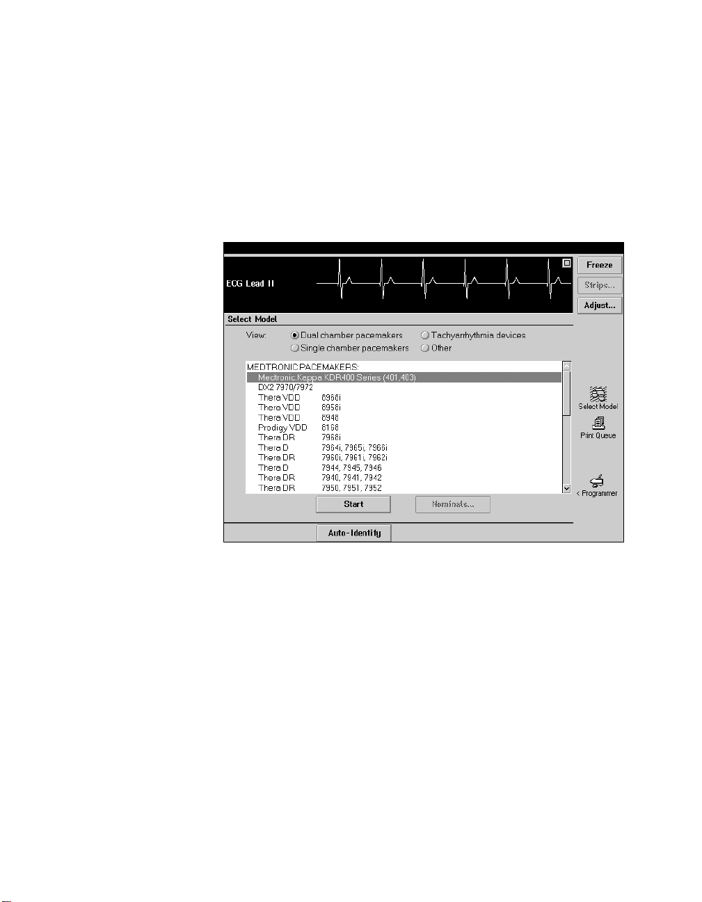
Starting a Patient Session
The procedure for starting a patient session begins at the Select
Model screen shown in the example below. This screen appears
upon completion of the self test when you turn the programmer
on and after you end a patient session.
Figure 3-2. Implantables Model Selection Screen
Starting a Patient Session Automatically
To start a patient session using Auto Identify:
1. Position the programming head over the patient’s implanted
device and continue to hold it steady.
2. Select the [Auto-Identify] button at the bottom of the screen.
After a few seconds of internal software loading, the
programmer displays the first task screen. Proceed as
described in “Selecting the Desired Function” on page 3-6.
3-4 InSync® Model 8040 Device Programming Guide
45

Model Not Identified – If a message states that the pacemaker
model cannot be identified, reposition the programming head and
repeat step 2 above or use the manual model selection procedure
described below. Automatic identification of the pacemaker
model will not occur if the programming head is not properly
positioned or if the presence of strong electrical interference
interrupts telemetry between the programmer and pacemaker.
Starting a Patient Session Manually
To start a patient session by selecting the model:
1. Select Other from the View options on the Select Model
screen.
1
2
46
3
2. Select
3. Select the [Start] button.
4. After a few seconds of internal software loading, the
InSync Model 8040 from the list of models.
programmer displays the first task screen. Proceed as
described in “Selecting the Desired Function” on page 3-6.
InSync® Model 8040 Device Programming Guide 3-5
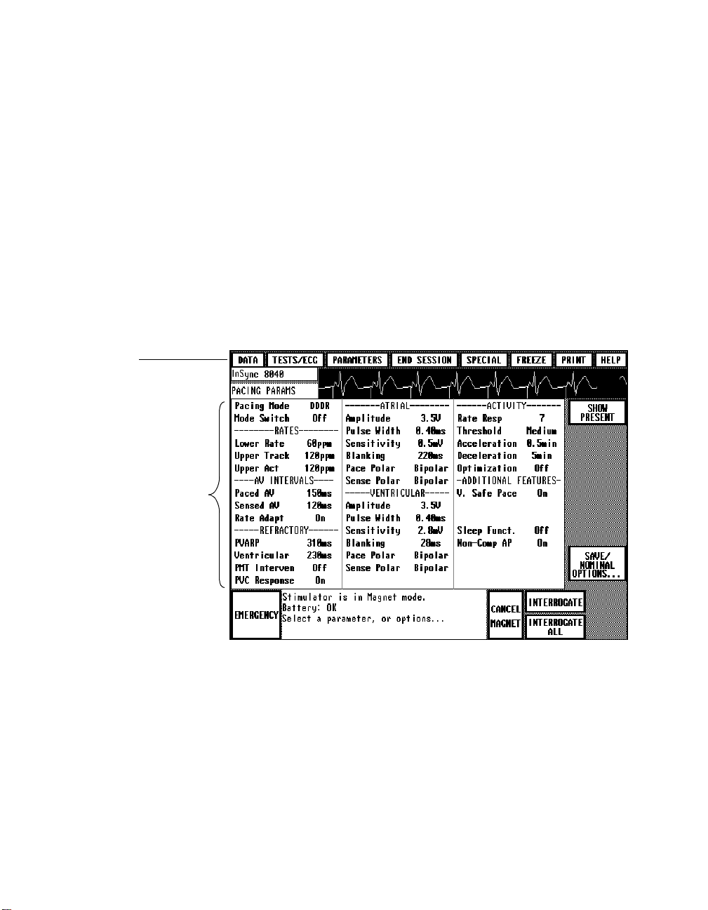
Selecting the Desired Function
Selecting the device model displays the Pacing Parameters screen
shown in the example below. This screen allows you to:
■
View the present parameter settings (see Chapter 4).
■
Program new parameter settings (see Chapter 6).
■
Proceed to another function.
To proceed to another function, select the appropriate button from
the “menu” buttons displayed across the top of the screen.
Menu Buttons
To display the present
parameter settings as
shown in this example,
you must interrogate the
device as follows:
Position the programming
head and press
INTERROGATE] or
[
INTERROGATE ALL].
[
Figure 3-3. Parameter Programming Screen
Navigating with the Menu Buttons
Except for the [END SESSION] and [FREEZE] buttons, selecting a
Menu button displays a list of function options as described on the
following page.
3-6 InSync® Model 8040 Device Programming Guide
47

Menu Button Description and Chapter Reference Possible Options
Select this button to display options for viewing data
retrieved from the device by interrogation, including: a
pacing data summary, battery and lead information, and
DATA SUMMARY
BATTERY/LEAD
SHOW DIAGNOSTICS GRAPH
a graph of Diagnostic data. Refer to Chapter 4.
Select this button to display options for viewing the
patient’s ECG and EGM and for conducting various tests
such as determining the patient’s stimulation threshold.
Refer to Chapters 5 and 7.
*
Select this button to display options for programming
pacing parameter values and for programming and using
the Diagnostic function. Refer to Chapter 6 and 8.
ECG/MARKERS/EGM (Ch 5)
THRESHOLD TEST (Ch 7)
SENSING TEST (Ch 7)
TEMPORARY TEST (Ch 7)
MEASURE ECG (Ch 7)
ACTIVITY TEST (Ch 7)
PACING PARAMETERS (Ch 6)
DIAGNOSTIC PARAMETERS (Ch 8)
ADDITIONAL PARAMETERS (Ch 6)
Select this button to end a patient session.
Select to access the: 1) Calibrate option, which applies
to using an external recorder; 2) Position Head Assist
CALIBRATE (Ch 9)
POSITION HEAD ASSIST(Ch 2)
option, which applies to using the Programming Head.
Refer to Chapters 9 and 2, respectively.
Select this button to freeze a 10-second segment of the
patient’s ECG. Refer to Chapter 5.
Select this button to display options for selecting the type
of report you want to print or the printer Trace mode.
Refer to Chapter 2.
Select this button to display options for selecting
informational help screens. Refer to Chapter 2.
*
An “EPS” option for conducting electrophysiologic studies also will be listed if 9886A or 9891A software has been
installed. Instructions for using this function are covered in a supplement supplied with the software.
CURRENT SCREEN REPORT
PARAMETER VALUES
DATA SUMMARY
BATTERY/LEAD DATA
DIAGNOSTICS DATA TABLE
THRESHOLD RESULTS
SENSING RESULTS
ACTIVITY THLD RESULTS
ACTIVITY EXERCISE TEST
MEASURED VALUES
WAVE FOR MS
WAVEFORM SEGMENT
FULL REPORT
TRACE...
CURRENT SCREEN
REPLACEMENT INDICATORS
MAGNET MODES
PROGRAMMER INFO
HOW TO PROGRAM
HOW TO INTERROGATE
48
InSync® Model 8040 Device Programming Guide 3-7

Ending a Patient Session
The programmer accumulates and temporarily stores certain data
generated during a patient session. This data facilitates parameter
programming and provides for the display of session-related
information. It is important to properly end each patient session
so that this data will clear from programmer memory when you
select a device model to begin a new patient session.
To end a patient session:
1. Select [END SESSION] from the Menu buttons at the top of the
screen.
This action displays a window that allows you to verify your
choice.
2. Select [
the session.
Ending the session returns you to the model selection screen,
which is the starting point for the next patient session.
Note: Once you end a patient session, you have two options to
retrieve the data reports generated during that session. You can
print the reports or transfer the reports to a computer diskette (see
Chapter 2).
Caution: You must print the accumulated reports or transfer
them to a diskette when you are prompted. This data will no
longer be available once you close the prompt (Print/Transfer
Reports?) window.
3-8 InSync® Model 8040 Device Programming Guide
49
OK] to end the session, or select [CANCEL] to continue

Retrieving System
General Desciption
Data 4
This chapter describes how you can display
information retrieved from an InSync device
by interrogation. You can use the four procedures
presented in this chapter to display:
1) The present programmed parameter settings.
2) A summary of battery and lead status and the
programmed status of the Diagnostics function.
3) Real-time measurements of device battery
condition and of parameters related to device
output and lead system status.
4) A graphic display of the event data accumulated
in device memory by the Diagnostics function if it
has been programmed to collect data.
Displaying Present Parameter
Settings 4-2
Displaying a Status
Summary 4-6
Displaying Battery and Lead
Information 4-11
Displaying a Graph of Recorded
Diagnostic Data 4-14
4
50
InSync® Model 8040 Device Programming Guide 4-1

Displaying Present Parameter Settings
You can quickly display the parameter settings to which the
patient’s device is programmed by selecting the appropriate
parameter screen. There are three such screens: 1) the Pacing
Parameters screen, 2) the Diagnostic Parameters screen, and 3) the
Additional Parameters screen.
To display the Present Pacing Parameters:
1. Select the [PARAMETERS] menu button
2. Select the
Note: If the [
lower right corner of the present screen, you can select it as an
alternative to the two-step procedure above.
PACING PARAMETERS option.
PACING PARAMETERS] button is displayed in the
Figure 4-1. Pacing Parameters Screen
If the device has been interrogated, this screen displays the
present parameter settings. (Subordinate parameters are not
displayed -- see next page.) To use this screen to program new
parameter settings, refer to the instructions in Chapter 6.
4-2 InSync® Model 8040 Device Programming Guide
51

Parameters Not Displayed
Each parameter listed below has one or more subordinate
programmable parameters that are not displayed on the Pacing
Parameters screen. These parameter subsets apply only when the
corresponding primary parameter is programmed to ON.
Parameter Corresponding Parameter Subset
Mode Switch Detect Rate
Rate Adapt
(Rate Adaptive AV Interval)
Start Rate
Stop Rate
Min. Paced AV
Min Sensed AV
Optimization
(Rate Response Optimization)
Rate Drop
(Rate Drop Response)
Sleep Funct.
(Sleep Function)
Life Style
Top Ra te
Bottom Rate
Confirmation Beats
Width Beats
Intervention Rate
Intervention Duration
Sleep Rate
Bed Time
Wake Time
To view the settings of the subordinate parameters, select the
primary parameter to open its value window. The subordinate
parameters and their present settings are displayed in the value
window as shown in this example.
52
Figure 4-2. Value window example showing subordinate parameters
InSync® Model 8040 Device Programming Guide 4-3

To display the present programmed parameter settings
controlling the Diagnostics function:
1. Select the [PARAMETERS] menu button.
2. Select the
The Diagnostic Parameters screen appears as shown in the
example below. If the Diagnostics function is not programmed
to collect data, the Type parameter shows a value of OFF.
DIAGNOSTIC PARAMETERS option.
Figure 4-3. Diagnostic Parameters Screen
Interrogate the device, if required, to display settings. Refer to
Chapter 8 for instructions on using the Diagnostics function.
4-4 InSync® Model 8040 Device Programming Guide
53

To display Additional Parameter Settings:
1. Select the [PARAMETERS] menu button.
2. Select the
ADDITIONAL PARAMETERS option.
The Additional Parameters screen appears as shown in the
example below. Interrogate the device, if required, to display
settings.
Figure 4-4. Additional Parameters Screen
54
The Additional Parameters screen displays the present settings for
the following parameters and provides access to the Status Reset
command.
Transtelephonic Monitor See Chapter 6.
Extended Telemetry See Chapter 6.
Device Serial Number See Chapter 6.
Status Reset (command) See Chapter 6.
InSync® Model 8040 Device Programming Guide 4-5

Displaying a Status Summary
You can display a summary of device battery and lead status and
the programmed status of the Diagnostics function by selecting
the Data Summary screen. This screen includes a display of
certain event data automatically accumulated by the device since
the last patient session.
Selecting the Data Summary Screen
To display the Data Summary screen
1. Select the [DATA] menu button.
Select these buttons
to view more data
(see page 4-10)
Note: Impedance of
the ventricular dual
lead system is
measured across the
parallel combination of
both leads.
2. Select the
The Data Summary screen appears as shown in the example
below. Data is not displayed unless an appropriate interrogation
has occurred. If necessary, interrogate the device to display the
summary data.
DATA SUMMARY option.
4-6 InSync® Model 8040 Device Programming Guide
55
Figure 4-5. Data Summary Screen

Battery/Lead Data
This section of the screen includes a summary of device battery
and lead status.
Estimated Time to Replacement
“Estimated Time to Replacement” is a calculated estimate of the
time (in months) remaining until device replacement is required.
This calculated estimate is an average value based on the
programmed parameter settings and the event summary data
accumulated by the device since the previous patient session.
Select the [
time to replacement and the estimated maximum, average, and
minimum values. Refer to “Estimated Time to Replacement” on
page 4-13 for information about the messages that can appear in
place of the estimated time value.
Note: Elective device replacement should not be based on the
estimated time to replacement. For this decision, use only the
elective replacement indicators or the battery status “Replace
Stimulator” message. When battery voltage indicates that device
replacement is required, the “Replace Stimulator” message
automatically appears on the screen in place of the estimated time
to replacement value.
MORE INFO] button for information about estimated
Lead Impedance
“Lead Impedance” is the measured electrical impedance
presented by the lead and electrode/tissue interface. If the pacing
mode is a dual chamber mode, the measured impedance for both
atrial and the ventricular lead system is displayed.
Note: Impedance of the ventricular dual lead system is measured
across the parallel combination of both leads.
56
InSync® Model 8040 Device Programming Guide 4-7

Diagnostic Parameters
This section of the screen shows the programmed status of the
Diagnostics function by displaying the present settings of the
Setup and Type parameters. No value for Setup is displayed if any
changes were made to the default settings provided by the Setup
option. A setting of “Off” for the Type parameter indicates that the
Diagnostics function has not been programmed to collect data.
Event Summary Data
Event Summary is a non-programmable device function that
operates continuously to collect the data described on the next
page. You can view this event data only on the Data Summary
screen and the Data Summary printout.
■
Event Summary shows data collected since the last patient
session. This data is automatically cleared from device
memory during each patient session and cannot be recalled
once the session has ended.
■
The listed dates, which show the period during which the
event data was collected, are based on the current setting of
the programmer’s calendar function. Data collection stops
when ERI occurs. In this case, the ending date is labeled as the
“ERI” date.
■
Under unusual circumstances, if a data error is detected,
“invalid data” can show in place of certain event values. This
condition should clear itself by the next patient session.
*
If one of the special single chamber modes (ADIR, VDIR, ADI, VDI) has been
programmed, “% Total Events” data is not available, and the “invalid data”
message is displayed.
4-8 InSync® Model 8040 Device Programming Guide
57
*

% Total Events
The data under this heading shows the percentage of the total
number of recorded beats that fall into each of the displayed pace/
sense event sequence categories.
*
For dual chamber pacing
modes, the event sequence categories are as follows:
AS-VS (Atrial Sense - Ventricular Sense)
AS-VP (Atrial Sense - Ventricular Pace)
AP-VS (Atrial Pace - Ventricular Sense)
AP-VP (Atrial Pace - Ventricular Pace)
For the VDD mode, the event sequence categories are:
AS-VS (Atrial Sense - Ventricular Sense)
AS-VP (Atrial Sense - Ventricular Pace)
VS (Ventricular Sense preceded by a ventricular event)
VP (Ventricular Pace preceded by a ventricular event)
For single chamber modes, two event categories are used:
PACED and SENSED.
PVCs
If the device has been operating in a dual chamber mode, Event
Summary displays the counted number of PVC “singles” and
“runs.” A PVC (premature ventricular contraction) is defined by
the device as a ventricular sense that follows a ventricular pace or
sense without an intervening atrial pace, atrial sense, or atrial
refractory sense.
58
SINGLES — Show the number of singly-occurring PVCs.
Runs — Show the number of runs consisting of two or more PVCs.
A greater-than symbol (>) appearing in front of the displayed
value indicates memory for this data is full and data collection has
stopped. Since PVC data collection applies only to dual chamber
modes, this feature is not displayed if a single chamber mode was
in effect during the monitoring period.
*
If one of the special single chamber modes (ADIR, VDIR, ADI, VDI) has been
programmed, “% Total Events” data is not available, and the “invalid data”
message is displayed.
InSync® Model 8040 Device Programming Guide 4-9

Mode Switch Episodes
“Mode Switch Episodes” is displayed in the Event Summary if the
Mode Switch parameter applies to the pacing mode in effect
during the monitoring period.
If Mode Switch is programmed ON, the number of mode switch
episodes occurring during the monitoring period is displayed. If
the number of episodes exceeds the range maximum (255), data
collection stops, and a greater-than symbol (>) appears in front of
the displayed value.
If Mode Switch is programmed off, the display shows “Off.”
Rate Resp. Optim. Episodes
“Rate Resp. Optim. Episodes” is displayed in the Event Summary
if the Optimization parameter applies to the pacing mode in effect
during the monitoring period.
If Optimization is programmed ON, the number of optimization
episodes occurring during the monitoring period is displayed. If
the number of episodes exceeds the range maximum (255), data
collection stops, and a greater-than (>) symbol appears in front of
the displayed value.
If Optimization is programmed off, the display shows “Off” in
place of a value.
Displaying More Data
To display more data, select the appropriate button as follows:
■
Select [BATTERY/LEAD] to view all battery and lead
measurements. See next section.
■
Select [DIAGNOSTIC PARAMETERS] to view the programmed
status of all Diagnostic parameters. Refer to Chapter 8.
■
Select [SHOW DIAGNOSTICS GRAPH] to display a graph of the
diagnostic data recorded in device memory. (If Type is “OFF,”
no data is collected for display.) Refer to Chapter 8.
4-10 InSync® Model 8040 Device Programming Guide
59

Displaying Battery and Lead Information
By selecting the Battery/Lead screen, you can display information
about the device battery and lead system based on real-time
measurements and calculations made at the time of device
interrogation. This information provides a detailed status of the
device battery and the output conditions pertaining to the pacing
lead system.
Selecting the Battery/Lead Screen
To display the Battery/Lead screen:
1. Select the [DATA] menu button.
Note: For the ventricular dual
lead system, Output Energy,
Lead Current, and Lead
Impedance are measured for
the parallel combination of both
leads.
2. Select the
Data does not appear unless an appropriate interrogation has
occurred. Interrogate the device, if necessary, to display or update
the battery and lead data. Interrogation may require several
seconds to complete.
BATTERY/ LEAD option.
60
Figure 4-6. Battery and Lead Data Screen
InSync® Model 8040 Device Programming Guide 4-11

Battery/Lead Screen
Interrogate the device if measurements are not displayed. This
process may take several seconds to complete.
Note: During the measurement process, the device paces at 100
ppm for several beats. (During these beats in a dual chamber
mode, the AV interval is 100 ms.)
Parameter Measurements
The Battery/Lead screen displays a battery status message and
real-time measurements and calculations for the device
parameters listed below.
Battery Status “OK” or “Replace Stimulator”
Estimated Time To
Replacement
Battery Voltage Present voltage of the device battery.
Battery Current Present current drain on the device battery
Battery Impedance Internal electrical impedance of the device
Pulse Duration Present programmed value of the pacing
Pulse Amplitude Present value of the pacing pulse amplitude.
Output Energy
Lead Current
Lead Impedance
Pacing Configuration Present programmed pacing configuration
*
For the ventricular dual lead system, Output Energy, Lead Current, and Lead
Impedance are measured for the parallel combination of both leads.
*
*
*
Calculated estimate of the average time
remaining until device replacement is
required. See page 4-13.
averaged over a pacing cycle.
battery.
pulse width.
Output energy contained in a single pacing
pulse.
Current delivered during a pacing pulse.
Electrical impedance presented by the lead
and electrode/tissue interface.
(unipolar or bipolar).
4-12 InSync® Model 8040 Device Programming Guide
61

Estimated Time to Replacement
“Estimated Time to Replacement” is a calculated estimate of the
average time (in months) remaining until device replacement is
required. This calculated estimate is based on the programmed
parameter settings and event summary data accumulated by the
device since the previous patient session.
Select the [
time to replacement and the estimated maximum, average, and
minimum values.
Note: Elective device replacement should not be based on the
estimated time to replacement. For this decision, use only the
elective replacement indicators or the battery status “Replace
Stimulator” message. When battery voltage indicates that it is
time for device replacement, the “Replace Stimulator” message
automatically appears on the screen in place of the estimated time
to replacement value.
The following messages can appear in place of the estimated time
value:
“Select MORE INFO ===>>>” – Estimated time to replacement
information is available only by selecting the [
This message appears when additional factors that affect the time
estimate are present and require an explanation. If less than 24
hours have elapsed since the previous patient session, a message
states that there is “insufficient event summary data accumulated
in the stimulator.” In this case, the estimated time to replacement
calculations assume that the patient is paced 100 percent of the
time.
MORE INFO] button for information about estimated
MORE INFO] button.
62
“Replace Stimulator” – Low battery voltage in the patient’s
device has tripped the ERI (elective replacement indicator).
Elective replacement of the device is now recommended.
InSync® Model 8040 Device Programming Guide 4-13
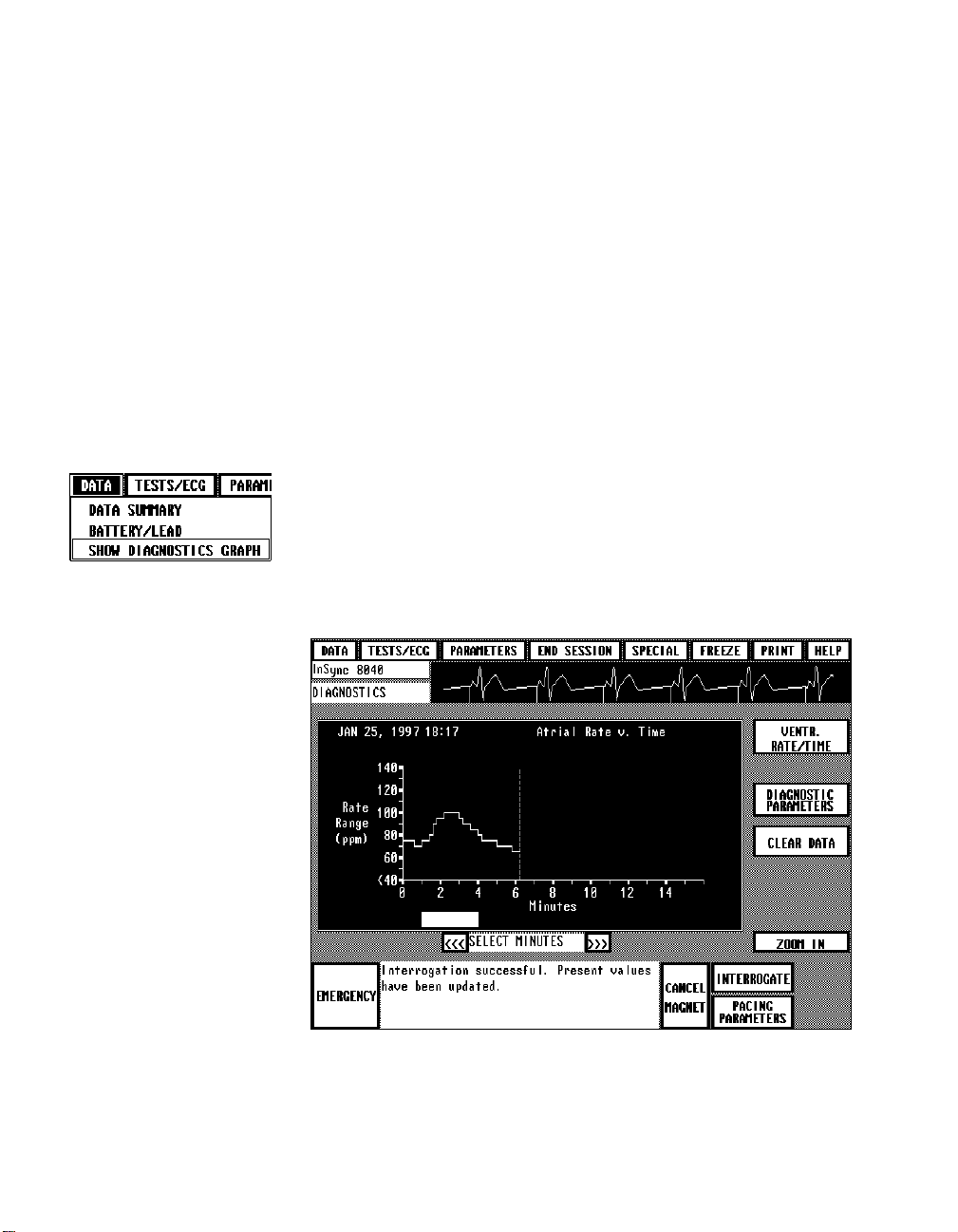
Displaying a Graph of Recorded Diagnostic Data
If the device has been previously programmed to record data for
the Diagnostics function, a graph of the data collected to date may
be viewed by selecting a Data option as described below. You can
also display this graph from the Diagnostic Parameters screen (see
Chapter 8) or from the Data Summary screen (see page 4-6).
Selecting the Graph Display Screen
To display the Diagnostics graph screen:
1. Select the [DATA] menu button.
2. Select the
The graph is not displayed unless an appropriate interrogation
has occurred. Interrogate the device, if necessary, to display the
graph.
SHOW DIAGNOSTICS GRAPH option.
Figure 4-7. Diagnostic Graph Example
4-14 InSync® Model 8040 Device Programming Guide
63

The type of information displayed by the graph depends on the
programmed status of the Diagnostics function.
Refer to Chapter 8 for information about the Diagnostics function
and viewing the graph.
To print the graph, you must select
CURRENT SCREEN REPORT
from the Print options while the graph is displayed (refer to
Chapter 2).
64
InSync® Model 8040 Device Programming Guide 4-15

4-16 InSync® Model 8040 Device Programming Guide
65

Displaying and
General Desciption
Printing the Patient’s
ECG and EGM 5
The procedures presented in this chapter describe
using the programmer’s ECG display and recording
functions. The procedures describe:
1) How to print a real-time recording of the patient’s
ECG.
5
2) How to select the high resolution ECG display.
3) How to inhibit device output to observe the
patient’s underlying rhythm.
4) How to freeze a 10-second segment of the patient’s
ECG and how to use the on-screen calipers.
5) How to select a Marker Channel Diagram to view
more detailed information about device operation.
InSync® Model 8040 Device Programming Guide 5-1
Printing the Patient’s ECG and
EGM 5-2
Displaying the Patient’s ECG and
EGM 5-5
Freezing the ECG Trace 5-11
Displaying a Marker Channel
Diagram 5-15
66

Printing the Patient’s ECG and EGM
At any time during a patient session, you can initiate a
continuous, real-time recording of the patient’s ECG as described
below.
Procedure
1. To start a recording of the patient’s ECG, press the desired
paper speed button.
25 mm/s
12.5 mm/s
Paper Advance
2. To stop the recording, press the same paper speed button.
3. Before you tear off the ECG strip, press the paper advance
button to advance the paper to a perforation.
Step 1 will interrupt any report being printed. Likewise, selecting
a Print option from the display screen will interrupt and cancel an
ECG recording in progress.
Note: Because the printed waveform recording provides a higher
resolution, it may show artifacts and events that do not appear on
the display screen.
5-2 InSync® Model 8040 Device Programming Guide
67

Annotations
ECG
Marker Telemetry
EGM Telemetry
Figure 5-1. ECG Printout Example with Markers and EGM
About the Recording
Annotation of Executed Commands – Information on the ECG
printout includes an indication of when certain commands to the
device occurred. When confirmation of the command is received,
the command name is printed at the appropriate point in the
margin above the waveform grid. Parameter values are not
printed except during a threshold test. A recording made during
threshold measurement will show each programmed test value at
the point it is programmed.
68
Marker Channel™ and EGM Telemetry – If the programming
head is over the patient’s device, the recording will include a trace
or traces of the telemetry being received from the device. In the
example above, the patient’s ECG is accompanied by “Marker”
telemetry and EGM telemetry. This combination of Marker and
EGM telemetry (atrial EGM if the pacing mode is dual chamber)
is the default setting and occurs automatically when you position
the programming head. As described later in this chapter, you can
select other types of telemetry to be displayed and recorded.
InSync® Model 8040 Device Programming Guide 5-3

ECG and EGM Trace adjustment – The ECG and EGM are
recorded according to control settings accessible from the ECG/
Markers/EGM display described in the next section (the ECG/
Markers/EGM display appears on several screens). These control
settings include ECG lead configuration (Lead I, Lead II, or Lead
III), amplitude scaling, and a filter ON/OFF option.
Missing Markers – A programming command or interrogation
momentarily interrupts the transmission of Marker Channel™
telemetry. This interruption can result in missing markers. The
point at which the command occurred is marked above the ECG
trace by a “down” and/or “up” arrow. The down arrow (▼)
indicates a transmitted command from the programmer; the up
arrow (▲) indicates a telemetry response from the device.
Displaying Pacing Artifacts
During processing and amplification of the patient’s ECG signal,
the programmer automatically detects and enhances pacing
artifacts so that they appear on the ECG display and printout.
Under certain conditions, some types of interference can trigger
artifact detection causing false artifacts to appear on the ECG.
With the 9790 programmer, you can turn the artifact display on or
off or make adjustments to reduce the effects of interference.
Turning the artifact display off allows you to monitor the patient’s
ECG without the appearance of pacing artifacts. Disabling this
function may be advantageous in the presence of troublesome
interference.
For instructions on setting up artifact detection, refer to
“Improving the Detection of Pacing Artifacts” in Chapter 9. The
Artifact Detection option is accessible by selecting the
Programmer icon in the tool palette on the Select Model screen.
Note: With the artifact display turned off, pacing artifacts will not
show on the programmer ECG display or printout. Once you turn
the artifact display off, it will remain off until you repeat the
procedure to turn it back on.
5-4 InSync® Model 8040 Device Programming Guide
69

Displaying the Patient’s ECG and EGM
By selecting the ECG/Markers/EGM screen, you can display a
high resolution view of the patient’s ECG. The ECG will be
accompanied by a trace of Marker Channel telemetry and EGM
telemetry if such telemetry is being received from the device. This
screen provides waveform trace adjustment controls and an
option for inhibiting device output.
Selecting the ECG/Markers/EGM Screen
To display the ECG/Markers/EGM screen:
1. Select the [TESTS/ECG] menu button.
2. Select the
If the programmer is connected to skin electrodes on the patient,
the screen displays the patient’s ECG. In this example, Marker and
ventricular EGM telemetry are being received from the device.
ECG/MARKERS/EGM option.
Figure 5-2. ECG/Markers/EGM Screen
70
InSync® Model 8040 Device Programming Guide 5-5

Adjusting the ECG and EGM Traces
The control buttons at the left of the trace display (see below) let
you adjust the displayed ECG and EGM.
To make an adjustment:
1. Select the appropriate button (see descriptions below).
2. Select the desired option from the displayed window of
options.
_________________________________________________________
Select to choose a different ECG Lead configuration.
Options: Lead I, Lead II, Lead III (Lead II is the default setting.)
_________________________________________________________
Select to change the ECG amplitude scaling.
Options: 1.0, 0.5, 0.2, 0.1, 0.05 mV/mm and Automatic.
“Automatic” sets scaling to the highest value that does not result in
clipping of the waveform peaks. Automatic is the default setting.
_________________________________________________________
Select to turn the ECG filter ON or OFF.
Options: Filter OFF (Bandwidth = 0.05 to 100 Hz)
The ON setting may improve clarity of the displayed and printed ECG in
the presence of interference. “ON” is the default setting.
_________________________________________________________
Indicates the patient’s present heart rate. This is not a control. The
displayed value is a beat-by-beat measurement derived from Marker
Channel telemetry. For ventricular and dual chamber modes, the value
will be the ventricular rate; for atrial modes, the value will be the atrial
rate.
_________________________________________________________
Select to display programmable waveform telemetry options.
(See telemetry programming procedure next page).
_________________________________________________________
Select to change the EGM amplitude scaling.
Options for:A. EGM = 1.0, 0.5, 0.2, 0.1, 0.05 mV/mm and Automatic
“Automatic” sets scaling to the highest value that does not result in
clipping of the waveform peaks. Automatic is the default setting.
_________________________________________________________
Filter ON (Bandwidth = 0.5 to 40 Hz)
V. EGM = 5.0, 2.0, 1.0, 0.5, 0.2 mV/mm and Automatic
(A+V) EGM = 1.0, 0.5, 0.2, 0.1, 0.05 mV/mm and Automatic
5-6 InSync® Model 8040 Device Programming Guide
71

Programming the Trace Telemetry Type
Default Telemetry – Positioning the programming head over the
patient’s device causes the device to transmit both Marker
telemetry and EGM telemetry (atrial EGM for dual chamber
modes). The examples on page 5-3 and page 5-5 show the
combination of Marker telemetry and EGM telemetry.
Programming Procedure – Use the following procedure to
temporarily program the telemetry to another type:
1. With the programming head in position over the device,
select this button.
2. Select the desired telemetry type from the options displayed
(see below).
3. Continue to hold the programming head in place for as long
as you want to view the programmed telemetry.
Telemetry Options – The programmable options for the type of
telemetry that can be displayed and recorded with the patient’s
ECG are as follows:
A. EGM This option displays atrial EGM and Marker
telemetry.
72
V. EGM This option displays ventricular EGM and Marker
telemetry.
Note: The ventricular EGM is a composite signal from
the parallel combination of both ventricular leads.
(
A+V) EGM This option displays atrial and ventricular EGM
telemetry combined as a single trace and Marker
telemetry.
MARKER This option displays Marker telemetry only. The
Marker trace appears in a larger format on the lower
trace display in place of the EGM.
SENSOR This option displays Sensor telemetry only. The trace
appears on the lower trace display in place of the
EGM.
InSync® Model 8040 Device Programming Guide 5-7

More About Marker Channel™ Telemetry
Note: An interrogation or programming command momentarily
interrupts Marker Channel™ telemetry. If this interruption occurs
at the moment a marker is scheduled, the marker is not displayed.
MARKER Telemetry – A trace of Marker telemetry depicts
device operation by showing Pace, Sense, and Refractory Sense
events as they occur within the device. Markers also depict
triggered pacing in the AAT or VVT mode and the beginning and
end of a Mode Switch episode when it occurs. These markers are
intended to facilitate interpretation of the ECG. Each Marker is
coded as follows:
Tabl e 5-1. Marker Coding
AP = Atrial Pace VP = Ventricular Pace
AS = Atrial Sense VS = Ventricular Sense
AR = Atrial Sense during
refractory
TP = Triggered Pace (AAT or VVT pacing mode)
MS = Mode Switch Episode (marks the beginning and the end)
ER = Error Marker (indicates a Marker signal that could not be decoded.
SENSOR Telemetry – Sensor telemetry transmits a single type of
marker to show “Sensor-Detect” events. A Sensor-Detect event
occurs each time the detected level of physical activity exceeds the
programmed Activity Threshold setting. Sensor markers thus
show response of the Activity sensor to physical activity of the
patient and are intended to facilitate evaluation of the Activity
Threshold setting.
VR = Ventricular Sense during
refractory
Sensor markers appear on the lower trace display as shown in
Figure 5-3. These markers are not annotated with letter codes.
5-8 InSync® Model 8040 Device Programming Guide
73

While Sensor markers
are displayed, heart rate
is not measured. This
number remains fixed.
Figure 5-3. Example Display Showing Sensor Markers
Inhibiting Device Output
The [INHIBIT PACING] button, which also appears on other screens
that show the ECG/Markers/EGM display, lets you temporarily
stop the pacing output of the patient’s device for such purposes as
observing the underlying rhythm.
Caution: The Inhibit function is intended for diagnostic and test
purposes. It should be used only under conditions of careful
patient monitoring and control.
Note: At any point during use of the Inhibit function, releasing
the [
PROGRAM] button or lifting the programming head away
from the site of the device for at least two seconds will restore
pacing output. In the event of a programmer malfunction or loss
of power, lift the programming head immediately.
74
Device blanking periods are minimized during use of the Inhibit
function to increase the window during which cardiac events can
be sensed. Sense markers appearing below the ECG will indicate
each sensed event.
InSync® Model 8040 Device Programming Guide 5-9

To inhibit device output:
1. Make any desired ECG trace adjustments before selecting
[
INHIBIT PACING].
2. Position the programming head and hold it steady for the
remainder of this procedure.
Note: To observe Sense markers and a display of the sensed
rate while you use the Inhibit function, select the [
MAGNET] button. (If device operation is not changed from the
magnet mode, Sense markers and the patient’s intrinsic rate
cannot be displayed.)
CANCEL
3. Select [
4. To inhibit device output, press and hold [
INHIBIT PACING] to prepare the programmer.
PROGRAM].
A message indicates that inhibition is occurring. The ECG
trace should show the absence of any pacing stimuli. To
obtain an ECG recording, press the desired paper speed key.
5. To restore pacing output, release [
PROGRAM].
Watch for confirmation that pacing output has been restored. If
confirmation is not received, lift the programming head to ensure
that pacing is restored.
5-10 InSync® Model 8040 Device Programming Guide
75

Freezing the ECG Trace
At any time during a patient session, you can freeze and display
10 seconds of the patient’s ECG and the accompanying telemetry
traces. On-screen calipers let you measure event timing intervals.
Selecting the FREEZE Button
To freeze and display a 10-second segment of the ECG
and telemetry trace:
➤ Select the [FREEZE] menu button.
This action displays the Freeze screen shown in the example
below. The frozen trace will begin to appear immediately or after
a pause of 5 or 10 seconds, depending on the selected Freeze
Option (see next page).
76
Figure 5-4. Freeze ECG Screen
InSync® Model 8040 Device Programming Guide 5-11

Changing the Freeze Window Timing
Timing of the 10-second window during which ECG and
telemetry signals are frozen depends on the present Freeze Option
setting.
To change the present Freeze Option:
1. Select the [FRZ OPTION...] button to display the options and
the present setting.
2. Select the desired timing option (see below).
The selected setting takes effect the next time you use the
Freeze function and remains in effect until you change it.
Freeze Timing Options
Selecting the [FRZ OPTION...] button displays the following
options:
■
Freeze Previous 10 Seconds — Freezes the 10 seconds of trace
that occurred just prior to selection of the [
■
Freeze Next 10 Seconds — Freezes the 10 seconds of trace that
occurs just after selection of the [
FREEZE] button.
FREEZE] button.
■
Freeze Previous 5 + Next 5 Seconds — Freezes the 5 seconds of
trace that occurred prior to selection of the [
plus the 5 seconds that occurs after the button selection.
Printing the Frozen Traces
Before you exit the Freeze screen, you can print the frozen 10second trace (
between the on-screen calipers (
option). Refer to Chapter 2 for information on printing reports.
5-12 InSync® Model 8040 Device Programming Guide
77
WAVEFORMS print option) or the portion of the trace
FREEZE] button
WAVEFORM SEGMENT print

Adjusting the Trace Displays
The control buttons at the left of the trace display let you
individually adjust the magnification of the frozen ECG and EGM
waveforms and change the time scale of trace display.
To make an adjustment:
1. Select the appropriate button (see below) to display a
window of options.
2. Select the desired option from the displayed window.
_________________________________________________________
Indicates the present ECG Lead configuration and ECG amplitude
scaling. This is not a control.
_________________________________________________________
Select to change the frozen ECG magnification factor.
Options: 1X, 2X, and 4X (1X is the default setting.)
_________________________________________________________
Select to change the frozen display time scale.
Options: 25, 50, 100 mm/sec (25 mm/sec is the default setting.)
_________________________________________________________
Indicates the telemetry type displayed on the lower trace display and the
EGM amplitude scaling when applicable. This is not a control.
_________________________________________________________
Select to change the frozen EGM magnification factor.
Options: 1X, 2X, and 4X (1X is the default setting.)
_________________________________________________________
1
78
1
This button does not appear if the present telemetry type shown in the box
above it is “MARKER” or “SENSOR.”
InSync® Model 8040 Device Programming Guide 5-13

Using the On-Screen Calipers
The position and scroll buttons below the trace display let you
control the position of two vertical cursors appearing on the trace
display. With these controls, you can use the cursors as on-screen
calipers to measure the time interval between events on the traces.
The small window above the
displays in milliseconds the interval between the cursors.
➎
➊ ➋ ➌➍
POSITION LEFT CURSOR buttons
➜
Left Cursor Right Cursor
➜
To use the caliper position and scroll buttons:
➤ Alternately press and release the appropriate button to effect
small movements or press and hold the button to effect larger
movements.
Button action reference:
➊ These two buttons move the left cursor to the right or left.
➋ These two buttons move the right cursor to the right or left.
➌ These buttons scroll the calipers to the right or left without changing
the space between them.
Select the [HOME] button to center the calipers on the screen one
second apart. You can use this button to retrieve the calipers if they
have been scrolled off the screen.
➍ To view the portion of the frozen traces not showing on the display,
use these two buttons to scroll the waveform traces to the right or left.
➎ This box displays the time interval between the cursors.
5-14 InSync® Model 8040 Device Programming Guide
79

Displaying a Marker Channel Diagram
Note: To view a Marker Channel Diagram as described below:
1) the pacing mode depicted by the ECG trace on the Freeze screen
must be dual chamber or VDD; and 2) pacing Marker annotations
or a Marker Channel trace must be present (the selected telemetry
type must be either Marker or EGM).
To display a Marker Channel Diagram:
➤ Select the [SHOW DIAGRAM] button on the Freeze screen.
The diagram will be drawn on the lower trace display as
shown in the example below.
80
Figure 5-5. Freeze Screen with Marker Channel™ Diagram
➤ To print the ECG trace and diagram, select the [PRINT] menu
button, and then select the
option.
➤ To return to the trace of Marker or EGM plus Marker
telemetry, select the [
appears in place of the [
InSync® Model 8040 Device Programming Guide 5-15
CURRENT SCREEN REPORT
SHOW MARKERS/EGM] button, which
SHOW DIAGRAM] button.

About the Marker Channel™ Diagram
The Marker Channel Diagram (see example below) shows more
details of device operation by depicting the various timing
intervals, including blanking and refractory periods. The diagram
is intended to further clarify operation of the device and simplify
analysis of the patient’s ECG.
Figure 5-6. Example of a Marker Channel™ Diagram
Note: If events portrayed on the diagram occur in very rapid
succession, the Pace and Sense marker annotations (P, S, R) may
not appear, and the supplemental labels (Act., Safe, PVC, and
NCAP) that define certain events may overlap. Overlapping
characters or labels displayed on the screen may not appear
exactly the same on the printout.
Note: In situations where the event rate is unusually high, the
Marker Channel Diagram may be less than 10 seconds in length
due to processing limitations.
Using the On-Screen Calipers
Operation of the POSITION LEFT/RIGHT CURSOR, CALIPER
SCROLL, and WAVEFORM SCROLL buttons is the same as
described on page 5-14.
Printing the Marker Channel™ Diagram
To print the Marker Channel Diagram, select the [PRINT] menu
button, and then select the
You can print a diagram only while it is displayed on the screen.
5-16 InSync® Model 8040 Device Programming Guide
81
CURRENT SCREEN REPORT option.

The printout lists the present parameter settings on which the
diagram is based and includes definitions of the lines, labels, and
symbols used in the diagram.
Interpreting the Diagram
Each Marker Channel Diagram is formed by a series of lines and
symbols that depict device operation. The pacing mode in effect is
printed above the ECG trace at the top of the chart.
P
A
V
P
P
A
V
Atrial and Ventricular Baselines – The diagram is formed along
two parallel baselines labeled “A” and “V.” Symbols depicting
atrial activity appear along the top side of baseline A; symbols
depicting ventricular activity appear along the bottom side of
P
P
P
P
P
P
baseline V. Sloped lines appearing between the two baselines
P
depict the timing relationship between atrial and ventricular
events.
P
Pace and Sense Markers – Short vertical lines extending upward
from baseline A and downward from baseline V are the event
A
V
P
markers received via Marker Channel telemetry. Each marker is
labeled according to the event it represents.
P (Pace) Output of a pacing stimulus.
S (Sense) A sensed event.
R (Refractory Sense) An event sensed within the refractory
period.
ER (Error) A marker that could not be decoded because of
interference or interrupted telemetry.
82
Act.
P
Supplemental Marker Labels – Supplemental labels indicate
when a marker is the result of one of the following conditions:
Act. An activity-driven pace.
Safe A ventricular safety pace.
PVC A device-defined premature ventricular contraction.
P
NCAP A non-competitive atrial pace.
InSync® Model 8040 Device Programming Guide 5-17

P
RS
R
Blanking and Refractory Periods – Rectangles on the A and V
baselines depict atrial and ventricular blanking and refractory
periods.
Solid Rectangles depict blanking periods.
S
P
P
P
P
SS
P
SS
S
Open Rectangles depict refractory periods. Vertical lines appearing
within the rectangle mark the timing of sense or pace events
occurring in the opposite chamber. Such lines may indicate the
start of a new refractory (and blanking) period.
Timing Lines – The sloped, horizontal, and vertical lines
appearing between the A and V baselines depict the timing
relationship between the atrial and ventricular events.
Downward Sloping Lines depict A-to-V timing (based on the
device’s operating AV interval) initiated by an atrial pace or sense
event. The course of this line results in a ventricular pace, unless
it is interrupted by a ventricular sense.
P
Upward Sloping Lines depict V-to-A timing (based on the device’s
operating pacing rate) initiated by a ventricular pace or sense
event. Except in the VDD mode, the course of this line results in
an atrial pace unless it is interrupted by an atrial sense or a PVC.
In the VDD pacing mode, a ventricular pace (not an atrial pace)
P
S
occurs if V-to-V timing completes before an atrial sense occurs.
Horizontal Lines depict any extension in the timing required to
maintain a proper pace schedule. In this example, the upper
tracking rate results in an extension of A-to-V timing. Another
example is non-competitive atrial pacing, which shows as an
extension of V-to-A timing.
Timing extensions are common in diagrams of the DDI(R) mode
because of the absence of atrial tracking.
Vertical Lines depict interruption of a timing interval by a sense or
the conclusion of a timing extension, which results in a pace.
5-18 InSync® Model 8040 Device Programming Guide
83

Error Conditions
Under certain conditions, the programmer may not be able to
properly determine device operation from the data available.
Most such conditions result i n the appearance of an error mes sage
on the diagram.
If an error message appears, you should reposition the
programming head and freeze another 10-second trace segment to
obtain a new Marker Channel Diagram.
Note: A Marker Channel Diagram cannot be displayed if an
interrogation or programming transmission occurred during the
10-second interval of the frozen trace.
Below is an explanation of the messages that indicate an error
condition.
“Missing Event” – This message appears if an event did not occur
when it was expected based on the interrogated data registered in
programmer memory. This situation can occur in the presence of
interference that interrupts telemetry.
Interruption of the diagram followed by the appearance of a
Threshold Margin Test (pacing at 100 ppm for three cycles)
indicates that movement of the programming head during
recording of the 10-second frozen trace opened and closed the
device reed switch. In this situation, the Threshold Margin Test
depicted on the diagram may be accompanied by one or more
“Missing Event” messages.
84
“Diagram Error” – This message indicates that a particular
sequence of events portrayed by the Marker trace cannot be
processed and properly displayed by the Marker Channel
Diagram.
“Bad Data” – This message indicates that the programmer has not
received the information it requires to complete the Marker
Channel Diagram. This can occur when there is an interruption or
fault in the telemetry being received - possibly due to interference
or movement of the programming head.
InSync® Model 8040 Device Programming Guide 5-19

5-20 InSync® Model 8040 Device Programming Guide
85

Programming the
General Desciption
Pacing Parameters 6
This chapter describes how to program:
- The permanent parameters controlling operation
of the patient’s implanted device.
- Nominal and saved parameter values.
- Transtelephonic Monitor and Extended Telemetry
parameters.
- The Status Reset command to verify or clear an
ERI status or clear a full electrical reset condition.
- The device serial number in the event it is cleared
from device memory by an electrical reset.
For instructions on programming the parameters of
the Diagnostics function, refer to Chapter 8.
Programming Pacing
Parameters 6-2
Programming Additional
Parameters 6-12
6
86
InSync® Model 8040 Device Programming Guide 6-1

Programming Pacing Parameters
To program changes to the permanent pacing parameters, begin
by selecting the Pacing Parameters screen. This screen displays
the present parameter settings and lets you select the parameters
and values to be programmed.
Selecting the Pacing Parameters Screen
To select the Pacing Parameters screen:
1. Select [PARAMETERS] menu button.
2. Select
Or select the [
the lower right corner of the present screen.
PACING PARAMETERS option.
PACING PARAMETERS] button if it is displayed in
Figure 6-1. Pacing Parameter Programming Screen
Present settings will not be shown unless an appropriate
interrogation has occurred. Interrogate the device, if required, to
display these settings.
6-2 InSync® Model 8040 Device Programming Guide
87

Refer to Appendix A for a list of the parameters and values
available for the InSync device.
Features of the Pacing Parameters Screen
Parameter Display – Following an interrogation, the screen
shows the present parameter settings. The screen displays only
those parameters that are applicable to the selected device model
and pertinent to the present pacing mode. Note that the
parameters are divided into labeled groups according to their
general function.
This button appears in the lower right corner of the screen only
when one or more new parameter values have been properly
selected (see “Restricted Parameter Interactions” on page 6-4).
The
PROGRAM key on the programming head will respond only
when the [
Special Options – The three buttons located at the right of the
parameter display may be useful during the programming
procedure described on page 6-5.
When you select new parameter values to program, these
“pending” values are displayed in place of the interrogated
present settings. To temporarily recall the present settings, press
and hold this button.
PROGRAM] button shows on the screen.
88
If you have saved a set of parameter values (see below), this
button will appear on the screen. Pressing and holding this button
will temporarily display these saved values.
Selecting this button displays options for: 1) clearing all pending
values from the parameter screen, 2) saving a set of parameter
values, and 3) recalling the set of saved values or nominal values
to the screen as pending values. (Refer to “Programming Nominal
and Saved Values” on page 6-10.)
InSync® Model 8040 Device Programming Guide 6-3

Restricted Parameter Interactions
Certain combinations of parameter values are restricted because
they are invalid or result in undesirable interactions. The
programmer recognizes these combinations and does not allow
programming until all parameter conflicts are resolved and all
parameter selection requirements are met. Refer to Appendix A
for more information on parameter programming requirements
and restrictions.
Restricted Parameter Values – Any parameter value that
conflicts with the setting of a present or pending parameter is
displayed in italics in the parameter value option window (see
step 2 of the programming procedure).
Parameter Interaction – If you select a restricted parameter value,
the display will indicate the interacting parameter values by
displaying the values in reverse video. You must select new values
to resolve the conflict before programming is allowed.
Parameter Entry Requirement – A solid, shaded rectangle
appearing where a parameter value should be displayed indicates
that a valid value for this parameter must be selected before
programming is allowed.
6-4 InSync® Model 8040 Device Programming Guide
89

General Parameter Programming Procedure
For specific parameter values and information, refer to
Appendix A.
To program one or more parameter values:
1. Select the desired parameter from those
displayed,
Press the stylus directly over the
parameter name or its value.
Lower Rate for example.
Note: : Select
intend to program a mode. Selecting a
mode displays the programmable
parameters pertinent to that mode.
2. From the window of value options,
select the desired value.
Except for Hysteresis, selecting a value
in italics results in a restricted parameter
interaction.
If the value window displays additional
parameters, refer to “Programming
Parameter Subgroups” on page 6-7.
Selecting a value closes the window. The
selected value appears in place of the
present value and is denoted as
“pending” by a dashed rectangle.
To clear a pending value from the screen,
select that parameter or value, and then
select [
window. To close the value window
without selecting a value, press
[
ACCEPT VALUE].
Pacing Mode first if you
CLEAR VALUE] in the value
90
InSync® Model 8040 Device Programming Guide 6-5

3. Repeat steps 1 and 2 to include any other parameters you
want to program.
Note: If you try to exit the screen before you program the
selected values, a pop-up window will provide the option to
continue with this procedure or clear the pending values and
exit the screen.
4. Position the programming head and select [
Select the [
PROGRAM] button to program all pending
PROGRAM].
parameter values. Hold the programming head in position
until the confirmation message appears.
Note: If the programming is interrupted, it is possible that
one or more of the parameter groups will not be programmed
and will still show pending values. In such cases, the
programming will not be confirmed, and the message box will
direct you to reselect [
PROGRAM].
6-6 InSync® Model 8040 Device Programming Guide
91

Programming Parameter Subgroups
For certain parameters that can be programmed ON or OFF, the
parameter value window displayed in step 2 of the general
programming procedure will list one or more additional
parameters that are subordinate to the selected “primary”
parameter. The procedures below cover the additional steps
required to select values for these subordinate parameters.
Programming Mode Switch
If the present setting for Mode Switch is ON or if you select ON, the
value window will list the present setting for the subordinate
parameter (as shown in the example below) and provide the
option to select a new value.
1. To select a value for this
parameter, use the same basic
procedure described in steps 1
and 2 of the general
programming procedure.
2. When you have selected the
desired value for Detect Rate,
select the [
button to close the primary
parameter value window.
ACCEPT VALUE]
92
If the present or pending value for Upper Tracking Rate is 165
ppm or above, the programmer automatically selects a pending
value for Detect Rate. The values of 185 and 190 bpm are not
selectable but will respectively appear as the pending value if
Upper Tracking rate is 175 or 180 ppm.
InSync® Model 8040 Device Programming Guide 6-7

Programming Rate Adaptive AV (Rate Adapt)
If the present setting for this parameter is ON or if you select ON,
the value window will list the present settings for the subordinate
parameters (as shown in this example) and provide the option to
select new values.
1. To select a value for each of
the parameters, use the same
basic procedure described in
steps 1, 2 and 3 of the general
programming procedure.
2. When the values for all four
parameters are as desired,
select the [
button to close the primary
parameter value window.
ACCEPT VALUE]
Programming Rate Response Optimization (Optimization)
If the present setting for this parameter is ON or if you select ON,
the value window will list the present setting for the subordinate
parameter (as shown below) and provide the option to select a
new value.
6-8 InSync® Model 8040 Device Programming Guide
93
1. To select a value for this
parameter, use the same basic
procedure described in steps
1 and 2 of the general
programming procedure.
2. When you have selected the
desired value for Lifestyle,
select the [
button to close the primary
parameter value window.
ACCEPT VALUE]

Programming Rate Drop Response (Rate Drop)
If the present setting for this parameter is ON or if you select ON,
the value window will list the present settings for the subordinate
parameters (as shown below) and provide the option to select new
values.
1. To select a value for each of
the parameters, use the same
basic procedure described in
steps 1, 2 and 3 of the general
programming procedure.
2. When the values for all six
parameters are as desired,
select the [
button to close the primary
parameter value window.
ACCEPT VALUE]
Programming the Sleep Function
If the present setting for this parameter is ON or if you select ON,
the value window will list the present settings for the subordinate
parameters as shown below and provide the option to select new
values.
94
1. To select a value for each of
the parameters, use the same
basic procedure described in
steps 1, 2 and 3 of the general
programming procedure.
Note: : The time options for
Bed Time and Wake Time are
based on a 24-hour clock
(examples: 12:00 midnight is
00:00, 8:00 AM is 8:00, 8:00 PM
is 20:00).
InSync® Model 8040 Device Programming Guide 6-9

From within the Bed Time or Wake Time value window, you
can display options for all hours of the day in 15-minute
increments by selecting the [
buttons to scroll the display of time options.
Note: Time information communicated to the device is based
on the current setting of the programmer’s clock/calendar
function. Verify that the current time setting of the
programmer’s clock is correct before programming the Sleep
Function. To verify the time, start and stop an ECG recording
by pressing the desired Paper Speed key or request any report
printout. The time is printed at the top of the printout. Refer
to Chapter 9 for instructions on setting the clock/calendar
function.
2. When the values for all three parameters are as desired, select
the [
ACCEPT VALUE] button to close the primary parameter
value window.
MORE <<<] or [MORE >>>]
Programming Nominal and Saved Values
The procedures below describe using the options available by
selecting the [
SAVE/NOMINAL OPTIONS...] button.
Programming Medtronic Nominal Values
To recall Medtronic nominal settings (“Medtronic Values”) to the
screen as pending values for programming:
1. Select the [
2. Select [
The respective parameter values will appear on the screen as
pending values. You can directly program these values or make
any desired changes prior to programming.
6-10 InSync® Model 8040 Device Programming Guide
95
MEDTRONIC VALUES] from the window of options.
SAVE/NOMINAL OPTIONS...] button.

Saving a Set of Parameter Values
To save the displayed present parameter values (those
interrogated from the patient’s device):
1. Select the [
2. Select [
SAVE/NOMINAL OPTIONS...] button.
SAVE PRESENT VALUES] from the window of options.
The displayed present parameter values will be saved in
programmer memory until you save another set of present values
or end the patient session. You can view the currently saved
values by selecting the [
SHOW SAVED] button on the Pacing
Parameters screen.
Note: : Unless some parameter values have already been saved,
using the [
INTERROGATE ALL] button as described in Chapter 2
will automatically save the present parameter settings.
Programming the Saved Set of Values
To recall the saved parameter values to the screen as pending
values for programming:
1. Select the [
2. Select [
The saved parameter values will appear on the screen as pending
values. You can directly program these values or make any
desired changes prior to programming.
SAVE/NOMINAL OPTIONS...] button.
SAVED VALUES] from the window of options.
96
InSync® Model 8040 Device Programming Guide 6-11

Programming Additional Parameters
Additional parameters include the Transtelephonic Monitor and
Extended Telemetry follow-up options, the device Serial Number,
and the Status Reset command. To access these parameter options,
select the Additional Parameters screen.
Selecting the Additional Parameters Screen
To display the Additional Parameters screen:
1. Select [PARAMETERS] menu button.
2. Select ADDITIONAL PARAMETERS option.
Parameter settings will not show unless an appropriate
interrogation has occurred. Interrogate the device, if necessary, to
display the settings.
6-12 InSync® Model 8040 Device Programming Guide
97

Programming Transtelephonic Monitor
Transtelephonic Monitor is a feature that can facilitate using
transtelephonic monitoring during a remote patient follow-up
procedure. The programmable options for this feature are ON and
OFF.
Warning: Do not program Transtelephonic Monitor to ON if the
patient has an implantable defibrillator.
To program Transtelephonic Monitor:
1. Select Trans Tele from the parameters listed on the Additional
Parameters screen.
2. From the window of options, select
3. Position the programming head and select [
the programming head steady until you see a confirmation.
ON or OFF as desired.
PROGRAM]. Hold
Programming Extended Telemetry
Programming Extended Telemetry to ON will cause the device to
continuously transmit EGM and Marker Channel telemetry for 24
hours.
Note: Because Extended Telemetry increases current drain on the
device battery, it should be used only when necessary.
To program Extended Telemetry:
1. Select Extend. Telem from the parameters listed on the
Additional Parameters screen.
2. From the displayed window of options, select
desired.
3. Position the programming head and select [
the programming head steady until you receive a
programming confirmation.
ON or OFF as
PROGRAM]. Hold
98
InSync® Model 8040 Device Programming Guide 6-13

Programming the Status Reset Command
If a screen message indicates that the device Elective Replacement
Indicator (ERI) has been set, you can use the Status Reset
command to verify present battery status as described below.
Verifying or Clearing an ERI Status
1. Select the Status Reset from the parameters listed on the
Additional Parameters screen.
2. From the option window, select
3. Position the programming head and select [
RESET.
PROGRAM].
Continue to hold the programming head steady while the
device automatically tests the present condition of its battery.
During this test, the device paces asynchronously at 100 ppm
for several beats. (During these beats in a dual chamber mode,
the AV interval will be 100 ms.)
■
If the test verifies the ERI status, no reset will occur.
■
If battery voltage has recovered, the ERI status is cleared,
and you can proceed to reprogram the parameter
settings.
Clearing a Device Electrical Reset
The Status Reset command can also be used to clear a full
electrical reset condition. Indication that a full electrical reset has
occurred is VVI pacing at 65 ppm and, in some cases, a device
serial number set to all zeros (000000).
Note: If a full electrical reset has occurred, you should contact
your Medtronic representative after using the Status Reset
command to clear this condition.
To clear a full electrical reset condition:
1. Select the Status Reset from the parameters listed on the
Additional Parameters screen.
2. From the option window, select
6-14 InSync® Model 8040 Device Programming Guide
99
RESET.

3. Position the programming head and select [
Continue to hold the programming head steady until
confirmation is received.
All parameters, including the device serial number, can now be
reprogrammed to their proper settings.
PROGRAM].
Programming the Device Serial Number
Serial number programming should not be used to change the
factory setting. This procedure is intended for reprogramming the
original serial number in the unlikely event it is lost from device
memory due to an electrical reset (see previous section about
programming the Reset command).
To reprogram the device serial number:
1. Select Serial Number from the list of parameters on the
Additional Parameters screen.
2. Using the on-screen keypad, enter each digit of the original
serial number. The selected numbers will appear in the small
window to the right of the keypad.
100
InSync® Model 8040 Device Programming Guide 6-15

3. If you make a mistake, select [CLEAR VALUE]. Otherwise,
select [
ACCEPT VALUE] to register the entered number as a
pending value.
4. Position the programming head and select [
the programming head steady until you receive a
programming confirmation.
PROGRAM]. Hold
6-16 InSync® Model 8040 Device Programming Guide
101
 Loading...