

Medtronic 74001, 74002 User Manual
Filename Date Time
UC200xxxxxx EN
4 x 8 inches (101 mm x 203 mm)
1X4 74001
2X4 74002
Pocket adaptor kit for spinal cord stimulation
1X4
2X4
Zestaw łącznika loży do stosowania w stymulacji rdzenia
kręgowego
1X4
2X4
Souprava adaptéru pro umístění do kapsy určeného ke
stimulaci míchy
1X4
2X4
Zsebadapter-készlet a gerincvelő stimulálására
1X4
2X4
Súprava implantovateľného adaptéra do kapsy na
stimuláciu miechy
1X4
2X4
Имплантируемый адаптер. Набор для стимуляции
спинного мозга.
1X4
2X4
Omurilik stimülasyonuna yönelik cep adaptör seti
1X4
2X4
Kit cu adaptor pentru buzunar pentru stimularea coloanei
vertebrale
Medtronic Confidential
ImplantManual.xsl -
LeadExtTemplate.fm
Template version: 04-22-2009
Implant manual • Podręcznik implantacji • Implantační
příručka • Beültetési útmutató • Príručka k implantátu •
Руководство по имплантации • İmplant el kitabı •
Manual implant
Rx only
M933784A004 Rev A
Printing instructions: Refer to the "Implant
Manual" category Table 1 in doc# A00002
for Neuro Core European Printing
2009
2009-07
Filename Date Time
UC200xxxxxx EN
4 x 8 inches (101 mm x 203 mm)
Medtronic Confidential
ImplantManual.xsl -
LeadExtTemplate.fm
Template version: 04-22-2009
M933784A004 Rev A
2009-07
Printing instructions: Refer to the "Implant
Manual" category Table 1 in doc# A00002
for Neuro Core European Printing
Filename Date Time
UC200xxxxxx EN
4 x 8 inches (101 mm x 203 mm)
Medtronic Confidential
ImplantManual.xsl -
LeadExtTemplate.fm
Template version: 04-22-2009
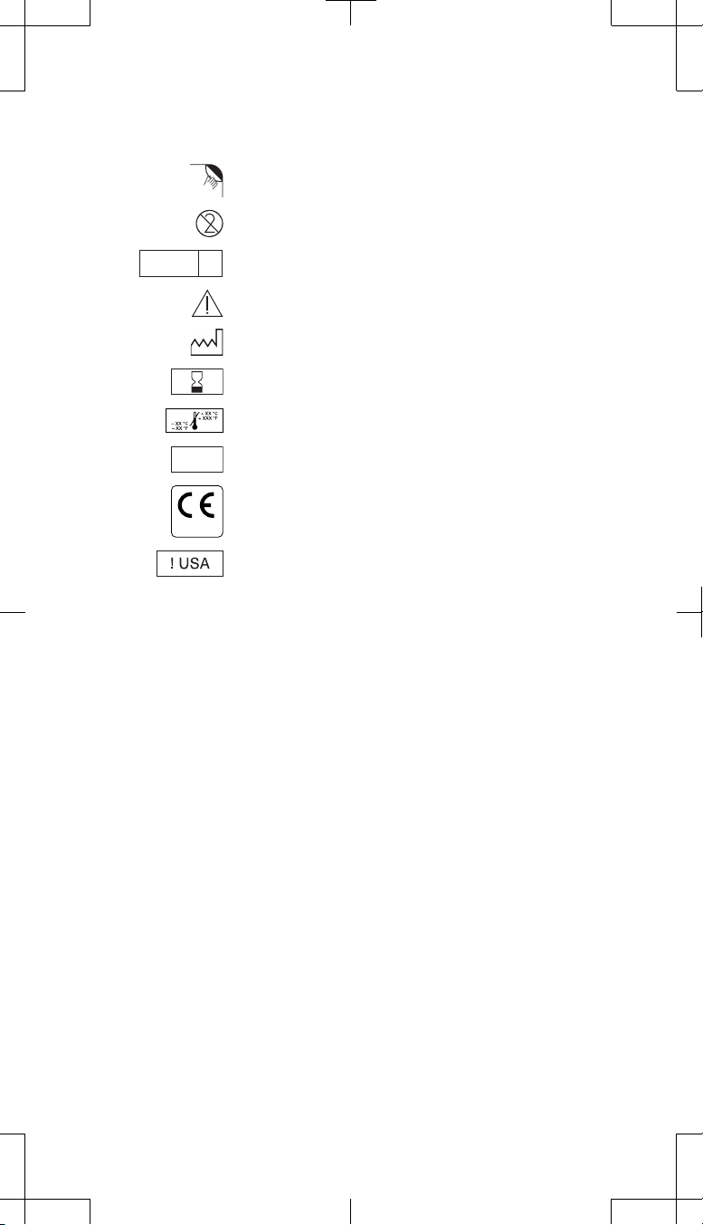
Explanation of symbols on product or package labeling
Refer to the appropriate product for symbols that apply.
Open here
Do not reuse
Sterilized using ethylene oxide
LOT
0123
EO
Caution, consult accompanying documents
Date of manufacture
Use by
Temperature limitation
Lot number
Conformité Européenne (European Conformity). This symbol
means that the device fully complies with European Directive
AIMD 90/385/EEC.
For USA audiences only
STERILE
M933784A004 Rev A
74001, 74002 2009-07 English 1
2009-07

Filename Date Time
UC200xxxxxx EN
4 x 8 inches (101 mm x 203 mm)
Medtronic Confidential
ImplantManual.xsl -
LeadExtTemplate.fm
Template version: 04-22-2009
Medtronic®, N'Vision®, PrimeADVANCED®, Restore®, RestoreADVANCED®,
RestorePRIME
®
, and RestoreULTRA® are registered trademarks of
Medtronic, Inc.
2 English 74001, 74002 2009-07
2009-07
M933784A004 Rev A

Filename Date Time
UC200xxxxxx EN
4 x 8 inches (101 mm x 203 mm)
Template version: 04-22-2009
Table of contents
Description 5
Package contents 5
Device specifications 5
Compatible quadripolar extensions 8
Compatible neurostimulators 8
Considerations before implant 9
Instructions for use 10
Positioning the patient 10
Reopening the neurostimulator pocket 10
Retracting the setscrews 10
Disconnecting the extension(s) from the explanted neurostimulator and
connecting to the pocket adaptor 11
One extension (4 electrodes) using one 1x4 pocket adaptor 11
One extension (4 electrodes) using one 2x4 pocket adaptor 11
Two extensions or a b ifurcated extension (8 combined elec trodes) using
a 2x4 pocket adaptor 12
Two extensions (4 electrodes each) using two 1x4 pocket
adaptors 13
Tightening the pocket adaptor setscrews 16
Connecting the pocket adaptor to the neurostimulator 17
Implanting the pocket adaptor with the neurostimulator 19
Checking system integrity 22
Completing the implant procedure 22
Physician communication to patient if the pocket adaptor is removed 22
At initial programming of the system 22
Medtronic Confidential
ImplantManual.xsl -
LeadExtTemplate.fm
Refer to the indications sheet for indications and related information.
Refer to the appropriate information for prescribers booklet for
contraindications, warnings, precautions, adverse events summary,
individualization of treatment, patient selection, use in specific
populations, resterilization, and component disposal.
Refer to System Eligibility, Battery Longevity, Specifications reference
manual packaged with the software application card for neurostimulator
selection, battery longevity calculations and specific neurostimulator
specifications.
Refer to the clinical summary booklet packaged with the
neurostimulator for information on the clinical study results of the
neurostimulation system and individualization of treatment.
74001, 74002 2009-07 English 3
M933784A004 Rev A
2009-07

Filename Date Time
UC200xxxxxx EN
4 x 8 inches (101 mm x 203 mm)
Medtronic Confidential
ImplantManual.xsl -
LeadExtTemplate.fm
Template version: 04-22-2009
4 English 74001, 74002 2009-07
2009-07
M933784A004 Rev A
Filename Date Time
UC200xxxxxx EN
4 x 8 inches (101 mm x 203 mm)
Medtronic Confidential
ImplantManual.xsl -
LeadExtTemplate.fm
Template version: 04-22-2009
Description
The Medtronic Models 74001 (1x4) and 74002 (2x4) Pocket Adaptors can be
used as a part of a spinal cord stimulation system for pain therapy.
The pocket adaptor is intended to be implanted with the new replacement
neurostimulator in the same pocket used for the explanted neurostimulator.
Implanting in the same neurostimulator pocket allows for a single-incision
procedure.
Package contents
Pocket adaptor
▪
Octapolar in-line neurostimulator plug
▪
Wrench, torque
▪
Product literature
▪
Warranty card
▪
Registration form
▪
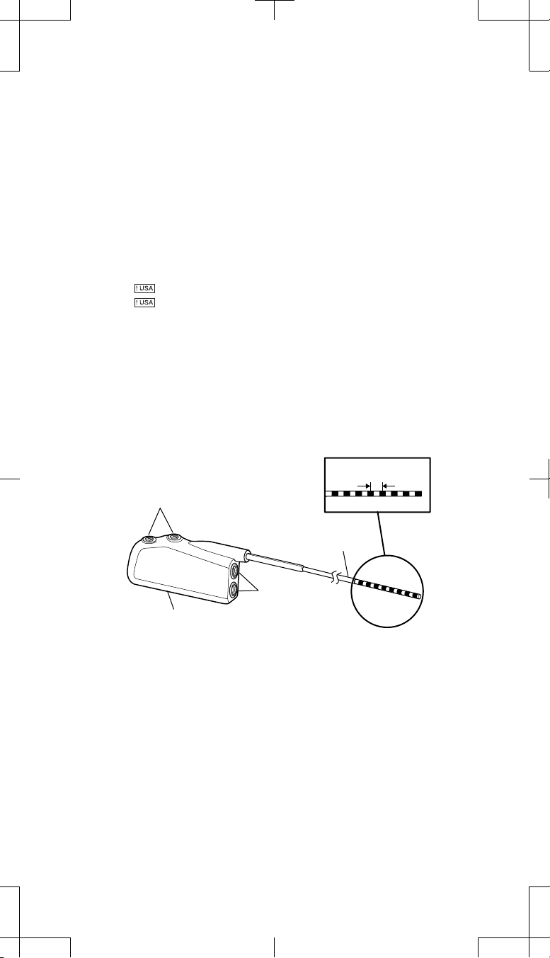
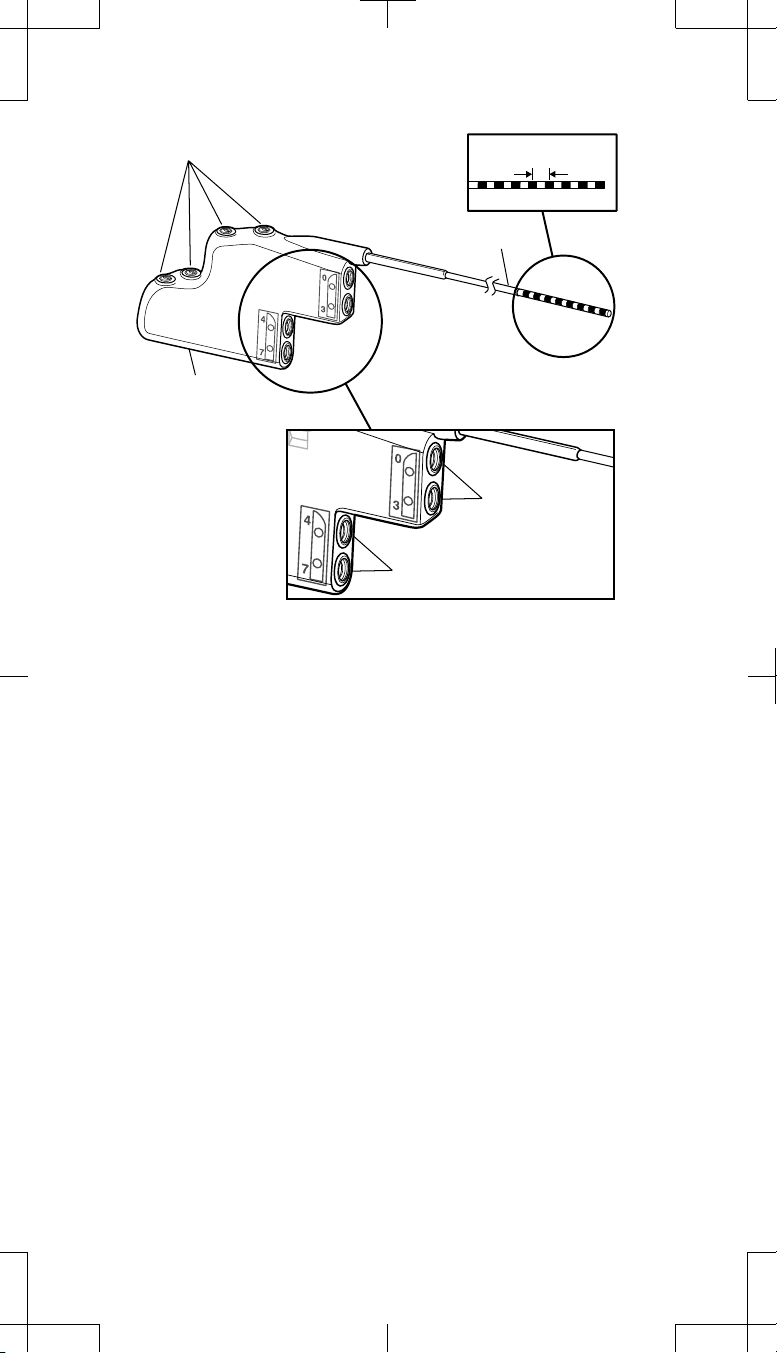
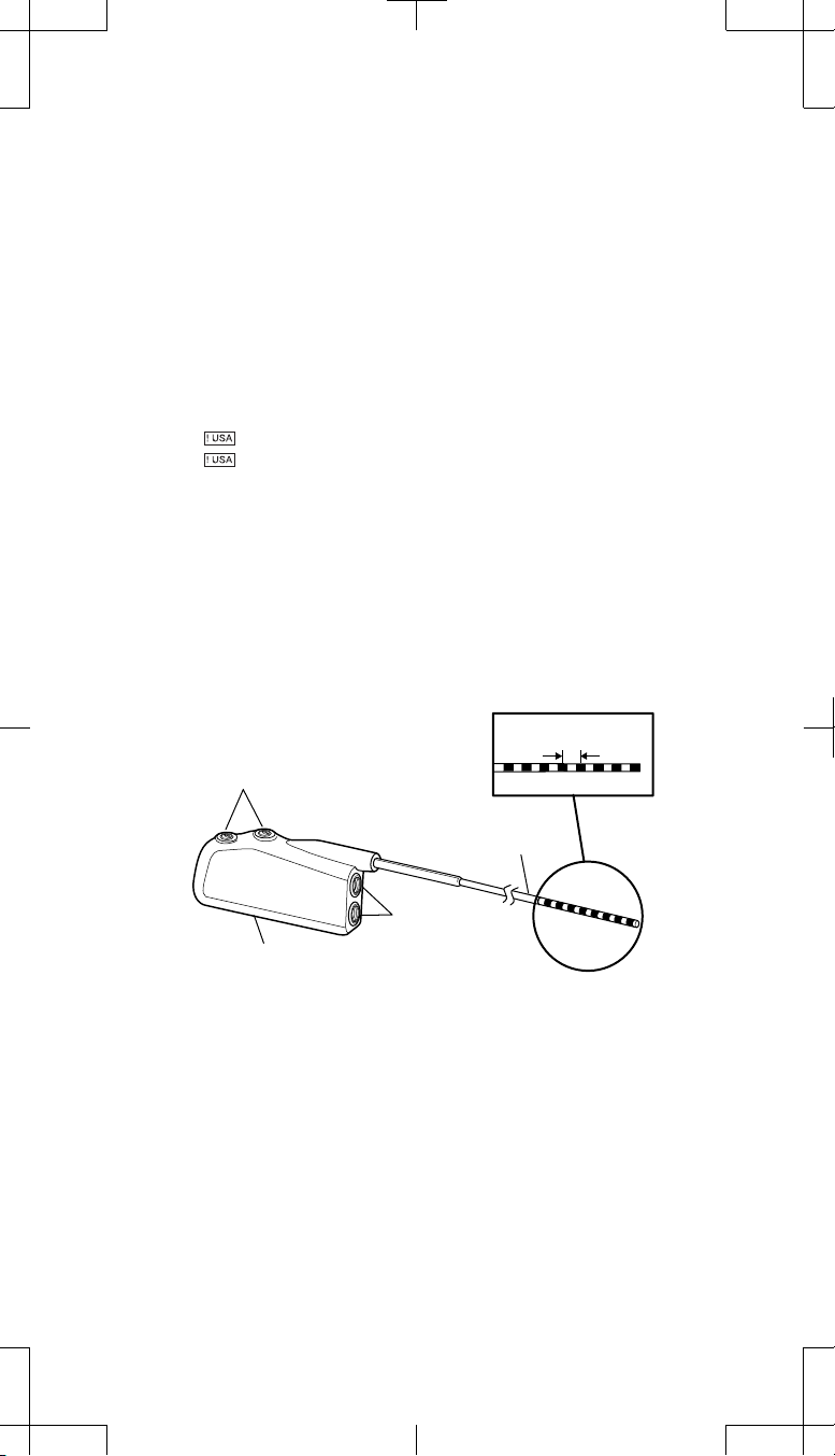
Device specifications
The pocket adaptor has connector ports on the distal end for connecting the
extension(s) and a 1x8 in-line connector on the proximal end.
The 1x4 pocket adaptor distal end connects to a Medtronic quadripolar
extension. The 2x4 pocket adaptor distal end connects to two Medtronic
quadripolar extensions or one bifurcated extension. The proximal end connects
to a neurostimulator.
See "Compatible quadripolar extensions" and "Compatible neurostimulators"
on page 8 for extension and neurostimulator compatibility with the pocket
adaptor.
Contact spacing
Setscrews (2)
Adaptor wire
Connector
port
Connector block
Distal Proximal
Figure 1. Model 74001 (1x4) pocket adaptor.
74001, 74002 2009-07 English 5
M933784A004 Rev A
2009-07
Filename Date Time
UC200xxxxxx EN
4 x 8 inches (101 mm x 203 mm)
Medtronic Confidential
ImplantManual.xsl -
LeadExtTemplate.fm
Template version: 04-22-2009
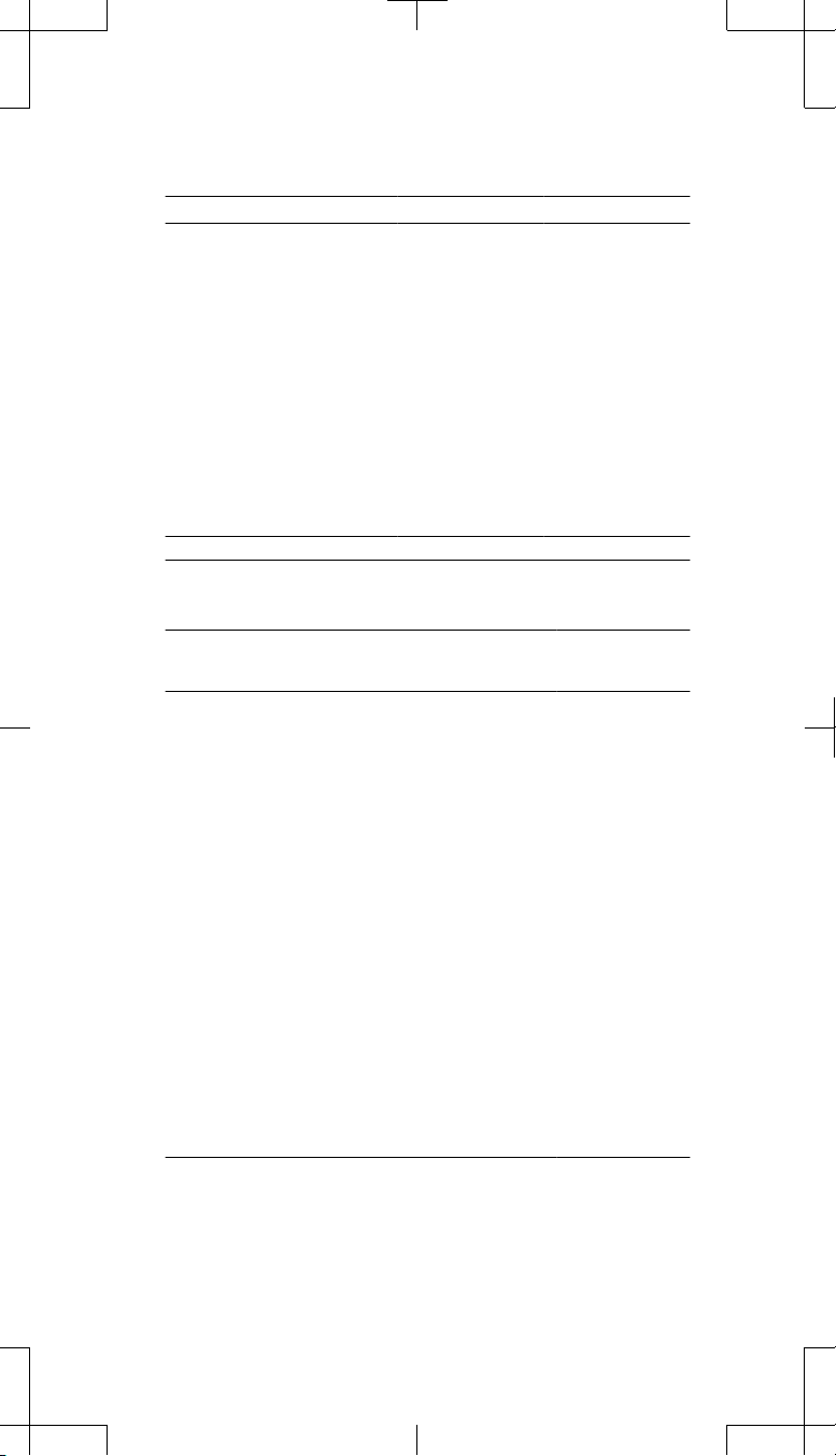
Setscrews (4)
Connector block
Distal
Contact spacing
Adaptor wire
Proximal
Connector port
for electrodes 0-3
Connector port
for electrodes 4-7
Figure 2. Model 74002 (2x4) pocket adaptor.
6 English 74001, 74002 2009-07
2009-07
M933784A004 Rev A
Filename Date Time
UC200xxxxxx EN
4 x 8 inches (101 mm x 203 mm)
Medtronic Confidential
ImplantManual.xsl -
LeadExtTemplate.fm
Template version: 04-22-2009
Table 1. Device specificationsa for the Models 74001 and 74002
Pocket Adaptors
Description
Model 74001 Model 74002
Resistance Maximum 50.0 Ω Maximum 50.0 Ω
Length 25.5 cm 27.4 cm
Distal end (adaptor connector block)
Connector ports Quadripolar Quadripolar
Height 16.6 mm 29.7 mm
Length 33.8 mm 45.6 mm
Thickness 7.1 mm 7.1 mm
Volume
2.66 cm
3
4.91 cm
3
Proximal end (adaptor wire, connects to the neurostimulator)
Connector Octapolar, in-line Octapolar, in-line
Contact spacing 2.8 mm 2.8 mm
Diameter
a
All measurements are approximate.
1.3 mm 1.3 mm
Table 2. Material of components in the Models 74001 and 74002 packages
Component
Material Material
contacts human
tissue
Pocket adaptor
Conductor wire MP35N No
Distal end (adaptor connector block)
Overmold Silicone rubber Yes
Contacts MP35N, stainless steel No
Setscrew connector block Titanium Yes
Grommets, seals Silicone rubber Yes
Setscrews Titanium Yes
Adhesive Silicone adhesive Yes
Proximal end (adaptor wire, connects to the neurostimulator)
Conductor wire insulation Fluoropolymer No
Contacts MP35N Yes
Insulation Polyurethane Yes
Neurostimulator plug Polyurethane Yes
Contact Stainless steel No
Wrench, torque
Handle Polymer Yes
Shaft
Stainless steel Yes
M933784A004 Rev A
74001, 74002 2009-07 English 7
2009-07
Filename Date Time
UC200xxxxxx EN
4 x 8 inches (101 mm x 203 mm)
Medtronic Confidential
ImplantManual.xsl -
LeadExtTemplate.fm
Template version: 04-22-2009
Compatible quadripolar extensions
Table 3 shows the compatibility of Medtronic quadripolar extensions with the
Models 74001 (1x4) and 74002 (2x4) Pocket Adaptors.
Table 3. Quadripolar extension compatibility with the Models 74001 and
Quadripolar extension
model number
a
7471
a
7472
7489 • •
7495 • •
7495 LZ • •
7496 • •
b
7498
a
The Models 7471 and 7472 Extensions are bifurcated on the proximal end.
b
The Model 7498 Extension is bifurcated on the distal end.
74002 Pocket Adaptors
Model 74001
(1x4)
• •
Model 74002
(2x4)
•
•
w Warning: Evaluate the suitability of a pocket adaptor for patients with an
implanted Model 7498 Extension. This extension is bifurcated on the distal
end, connecting two leads in parallel. If one lead should break, an
impedance measurement may yield a result in the normal range because
of the presence of the second lead. Thus, open circuits may be difficult to
detect, which can increase the potential for risks related to MRI.
Compatible neurostimulators
The following are the Medtronic 16-electrode neurostimulators that are
compatible with the Models 74001 (1x4) and 74002 (2x4) Pocket Adaptors:
RestorePRIME Model 37701
▪
PrimeADVANCED Model 37702
▪
Restore Model 37711
▪
RestoreULTRA Model 37712
▪
RestoreADVANCED Model 37713
▪
8 English 74001, 74002 2009-07
2009-07
M933784A004 Rev A

Filename Date Time
UC200xxxxxx EN
4 x 8 inches (101 mm x 203 mm)
Considerations before implant
The pocket adaptor is intended for neurostimulator revisions only and not
▪
for extension or lead revisions, which would require retunneling. The
pocket adaptor may not be appropriate if the lead or extension needs to
be replaced.
If the implanted neurostimulator is still viable, perform a system integrity
check with the neurostimulator before the d ay of implant surgery to ensure
all leads and extensions are still functioning.
Existing quadripolar extensions should not be replaced with the same or
▪
another quadripolar extension model if using the pocket adaptor.
The pocket adaptor is not compatible or needed if a newer model
▪
extension (eg, Model 37083) is used to replace a quadripolar extension.
Consider using the pocket adaptor when retunneling is not desired.
▪
Evaluate the patient's overall suitability for a system containing a pocket
▪
adaptor. Consideration should be given to cosmesis, erosion, trauma,
infection, and patient comfort and risk factors (eg, age, skin thickness,
diabetes, chronic steroid use).
Consider the following when choosing an appropriate pocket adaptor
▪
model:
number of existing leads and extensions
–
electrode numbering for programming
–
number of components that will be implanted in the pocket
–
future expansion for additional leads
–
The 2x4 pocket adaptor has the same electrode numbering as the 4- and
▪
8-electrode neurostimulators and allows for future expansion into the
second socket of the new replacement neurostimulator. See "At initial
programming of the system" on page 22 for more information on
electrode numbering.
Medtronic Confidential
ImplantManual.xsl -
LeadExtTemplate.fm
Template version: 04-22-2009
M933784A004 Rev A
74001, 74002 2009-07 English 9
2009-07

Filename Date Time
UC200xxxxxx EN
4 x 8 inches (101 mm x 203 mm)
Medtronic Confidential
ImplantManual.xsl -
LeadExtTemplate.fm
Template version: 04-22-2009
Instructions for use
Implanting physicians should be experienced in neurostimulation system
implant procedures and should be thoroughly familiar with all product labeling.
# Cautions:
▪ Do not store or transport the kit components or accessories above
57°C (135°F) or below -34°C (-30°F). Temperatures outside this range
can damage device components.
▪ Do not bend, kink, or stretch the extension or adaptor, which may
damage the component.
▪ Do not use any instrument to handle the extension or adaptor. The
force may break the wires. Broken wires may create an open circuit,
resulting in loss of stimulation or component failure and requiring
surgical replacement.
Positioning the patient
1. Locate the neurostimulator pocket and position the patient accordingly.
2. Before opening the adaptor package, verify the model number, use-by
date, and connector type.
Reopening the neurostimulator pocket
# Caution: When using sharp instruments near the implanted
neurostimulator, be extremely careful to avoid nicking or damaging the
extension. Damaging the extension may require surgical replacement.
1. Make an incision to access the neurostimulator.
2. Remove the neurostimulator from the pocket, taking care not to pull
excessively on the extension, which could cause lead dislodgement.
3. Perform a system integrity check:
Notes:
To ensure the implanted leads and extensions are functional, use the
▪
currently implanted neurostimulator for the system integrity check
before disconnecting any extensions. The pocket adaptor may not be
appropriate if an extension needs to be replaced.
If the neurostimulator battery is depleted, wait to perform the system
▪
integrity check until the "Disconnecting the extension(s) from the
explanted neurostimulator and connecting to the pocket adaptor"
procedure on page 11, when the extension is connected to the
adaptor. At that point, use a Medtronic Model 37021 or Model 37022
External Neurostimulator along with a Model 3550-31 snap-lid
screening cable attached to the proximal end of the pocket adaptor to
perform the electrode impedance check.
Do not use the patient programmer to perform system integrity checks.
▪
Only use the clinician programmer.
4. Reduce or expand the size of the pocket to accommodate the pocket
adaptor and the new neurostimulator. However, do not make the pocket
any larger than what is needed. Too large of a pocket may cause patient
twiddling, component migration, or flipping of the neurostimulator.
Note: Refer to the neurostimulator implant manual for the proper
subcutaneous pocket depth placement of the neurostimulator below the
skin. To allow for successful telemetry and/or recharge operation, ensure
that the subcutaneous pocket does not allow the neurostimulator to fall
below the required measurement beneath the skin.
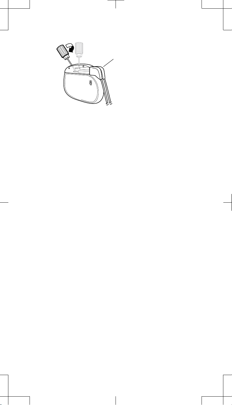
Retracting the setscrews
1. Using the torque wrench, retract the setscrews within the explanted
neurostimulator connector block (Figure 3).
10 English 74001, 74002 2009-07
2009-07
M933784A004 Rev A
Filename Date Time
UC200xxxxxx EN
4 x 8 inches (101 mm x 203 mm)
Medtronic Confidential
ImplantManual.xsl -
LeadExtTemplate.fm
Template version: 04-22-2009
To maintain left and right side
connectivity, do not remove the
extensions at this point.
Figure 3. Retract the setscrews within the explanted neurostimulator using the
2. Check the pocket adaptor conne ctor block and determine if any setscrews
obstruct the connector ports. If needed, partially retract the setscrews.
a. To partially retract a setscrew, use the torque wrench and turn the
setscrew counterclockwise only until the connector port is
unobstructed.
torque wrench.
Disconnecting the extension(s) from the explanted neurostimulator and connecting to the pocket adaptor
Use the appropriate procedure in this section specific to the extension and
pocket adaptor configuration.
# Cautions:
▪ Do not use saline or other ionic fluids at connections, which could
result in a short circuit.
▪ Before connecting components, wipe off any body fluids and dry all
connections. Fluids in the connection may result in stimulation at the
connection site, intermittent stimulation, or loss of stimulation.
▪ Do not pull the extensions taut. Pulling the extensions taut may result
in a short or open circuit or migration of implanted components.
One extension (4 electrodes) using one 1x4 pocket adaptor
1. Remove the extension connector from the neurostimulator socket.
2. Wipe the extension connector pins with sterile gauze. If necessary, use
sterile (United States Pharmacopeia [USP]) water or a nonionic antibiotic
solution.
3. Ensure the connector pins and the adaptor connector ports are dry and
clean.
4. Insert the extension connector pins into the 1x4 pocket adaptor connector
port until fully seated.
5. Proceed to "Tightening the pocket adaptor setscrews" on page 16.
One extension (4 electrodes) using one 2x4 pocket adaptor
1. Remove the extension connector from the neurostimulator socket.
2. Wipe the extension connector pins with sterile gauze. If necessary, use
sterile (United States Pharmacopeia [USP]) water or a nonionic antibiotic
solution.
3. Ensure the connector pins and the adaptor connector ports are dry and
clean.
4. Insert the extension connector pins into Connector Port 1 (top port) of the
2x4 pocket adaptor until fully seated.
5. Insert the two-pronged plug from the Model 3550-09 accessory kit into
Connector Port 2 of the adaptor.
6. Proceed to "Tightening the pocket adaptor setscrews" on page 16.
M933784A004 Rev A
74001, 74002 2009-07 English 11
2009-07
Filename Date Time
UC200xxxxxx EN
4 x 8 inches (101 mm x 203 mm)
Two extensions or a bifurcated extension (8 combined electrodes) using a 2x4 pocket adaptor
Medtronic Confidential
ImplantManual.xsl -
LeadExtTemplate.fm
Template version: 04-22-2009
# Cautions:
▪ Use only a 2x4 pocket adaptor for systems using the Model 7471 or
the Model 7472 bifurcated extension. Using two 1x4 pocket adaptors
with these bifurcated extensions will cause electrode numbering
mismatches when programming and cause some neurostimulator
features to be inoperable.
▪ Maintain left and right side connectivity for a two-extension or a
bifurcated-extension system when disconnecting the extensions from
the explanted neurostimulator and connecting to the 2x4 pocket
adaptor. If left and right side connectivity is not maintained, the current
electrode configuration will not be maintained in the new
neurostimulator.
▪ Do not tie ligatures around the extension or adaptor wire to distinguish
left or right side. Ligatures can damage the insulation.
This procedure di sconnects and connects one extension at a time to the adaptor,
which helps to maintain the left and right side connectivity.
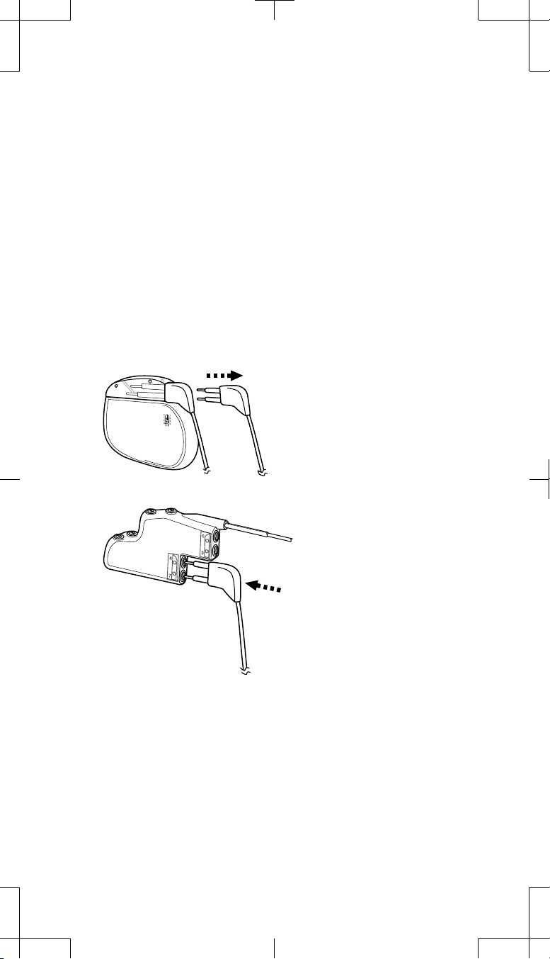
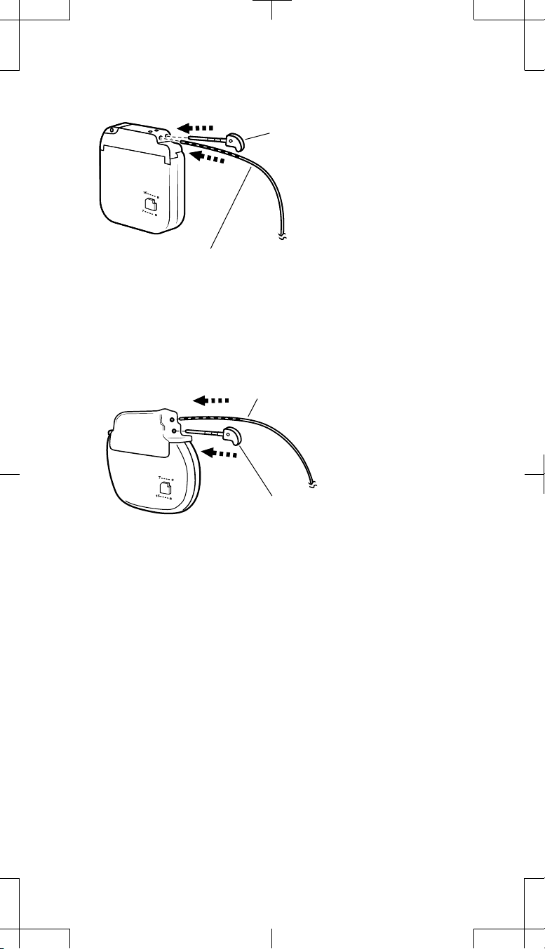
1. Remove Extension 2 from Socket II (back socket) of the explanted
neurostimulator (Figure 4).
Remove Extension 2 (electrodes 4-7)
from Socket II (back socket) of the
explanted neurostimulator.
Insert Extension 2 into
Connector Port 2 (bottom port) of
the 2x4 pocket adaptor.
Figure 4. Remove Extension 2 from Socket II of the explanted neurostimulator
and insert into Connector Port 2 of the 2x4 pocket adaptor.
Wipe the extension connector pins with sterile gauze. If necessary, use
2.
sterile (United States Pharmacopeia [USP]) water or a nonionic antibiotic
solution.
3. Ensure the connector pins and the adaptor connector ports are dry and
clean.
4. Insert the connector pins of Extension 2 into Connector Port 2 (bottom port)
of the 2x4 pocket adaptor until fully seated (Figure 4).
12 English 74001, 74002 2009-07
2009-07
M933784A004 Rev A
Filename Date Time
UC200xxxxxx EN
4 x 8 inches (101 mm x 203 mm)
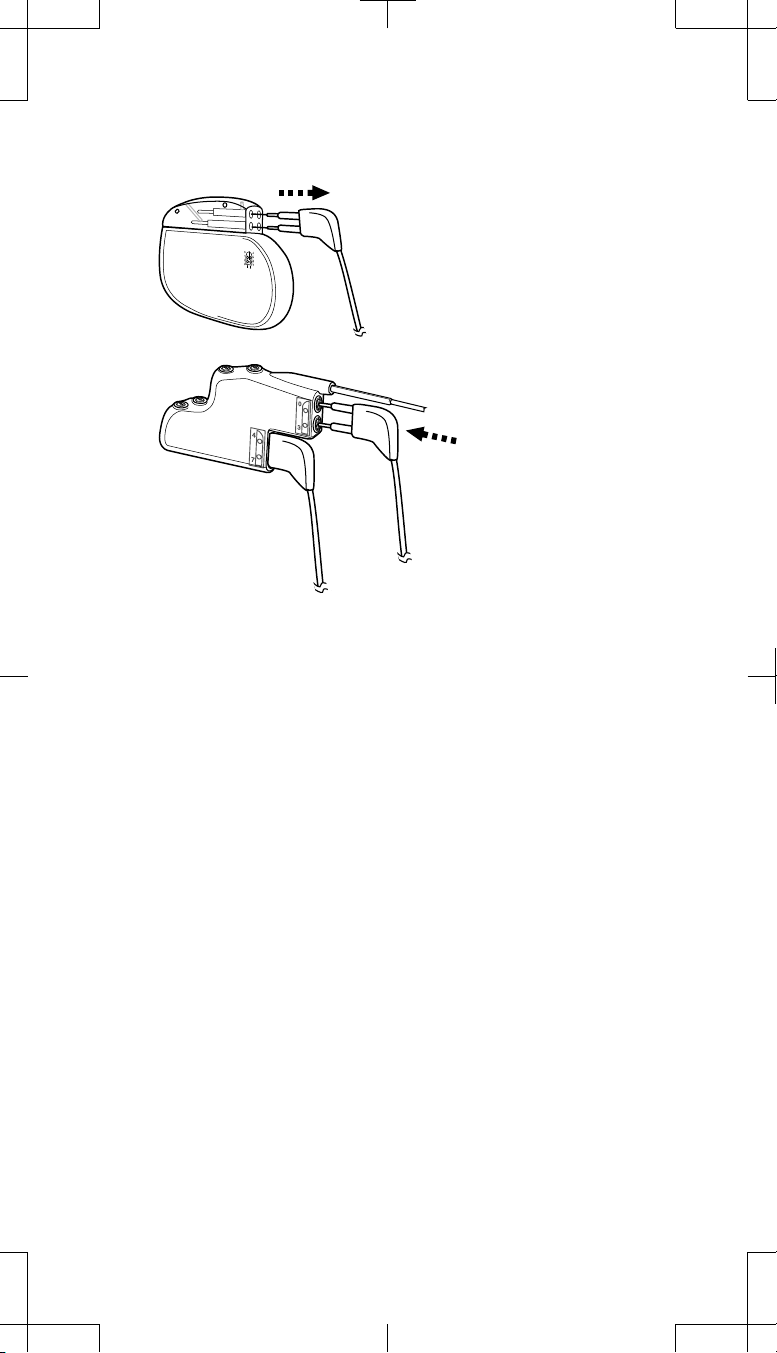
5. Remove Extension 1 from Socket I (front socket) of the explanted
neurostimulator (Figure 5).
Remove Extension 1 (electrodes 0-3)
from Socket I (front socket) of the
explanted neurostimulator.
Insert Extension 1 into
Connector Port 1 (top port)
of the 2x4 pocket adaptor.
Medtronic Confidential
ImplantManual.xsl -
LeadExtTemplate.fm
Template version: 04-22-2009
Figure 5. Remove Extension 1 from Socket I of the explanted neurostimulator
and insert into Connector Port 1 of the 2x4 pocket adaptor.
6. Wipe the extension connector pins with sterile gauze. If necessary, use
sterile USP water or a nonionic antibiotic solution.
7. Ensure the connector pins and the adaptor connector ports are dry and
clean.
8. Insert the connector pins of Extension 1 into Connector Port 1 (top port)
of the 2x4 pocket adaptor until fully seated (Figure 5).
9. Proceed to "Tightening the pocket adaptor setscrews" on page 16.
Two extensions (4 electrodes each) using two 1x4 pocket adaptors
# Cautions:
▪ Use only a 2x4 pocket adaptor for systems using the Model 7471 or
the Model 7472 bifurcated extension. Using two 1x4 pocket adaptors
with these bifurcated extensions will cause electrode numbering
mismatches when programming and cause some neurostimulator
features to be inoperable.
▪ Maintain left and right side connectivity for a two-extension system
when disconnecting the extensions from the explanted
neurostimulator, connecting to the 1x4 pocket adaptors, and then
connecting the adaptors to the new neurostimulator. If left and right
side connectivity is not maintained throughout all connections, the
current electrode configuration will not be maintained in the new
neurostimulator.
▪ Do not tie ligatures around the extension or adaptor wire to distinguish
left or right side. Ligatures can damage the insulation.
Proceed as follows:
1. Remove Extension 2 from Socket II (back socket) of the explanted
neurostimulator (Figure 6a on page 14).
M933784A004 Rev A
74001, 74002 2009-07 English 13
2009-07
Filename Date Time
UC200xxxxxx EN
4 x 8 inches (101 mm x 203 mm)
Medtronic Confidential
ImplantManual.xsl -
LeadExtTemplate.fm
Template version: 04-22-2009
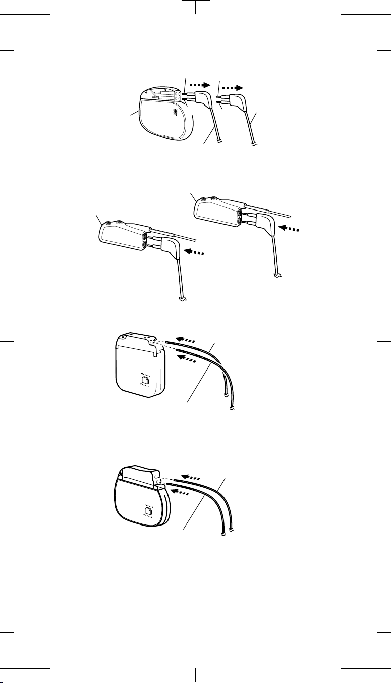
(a)
Explanted
neurostimulator
(b)
Adaptor 1
Insert Extension 1 into
Adaptor 1 (electrodes 0-3).
(c)
Electrodes 3, 0
2, 1
Remove Extension 1
from front socket.
Adaptor 2
Insert Adaptor 2 pin into
Neurostimulator Socket II
(back socket).
Electrodes 7, 4
Remove
6, 5
Adaptor 2 (electrodes 4-7).
Extension 2 from
back socket.
Insert Extension 2 into
Insert Adaptor 1 pin into
Neurostimulator Socket I
(d)
Insert Adaptor 2 pin into
Neurostimulator Socket II
Figure 6. Connecting two extensions to two 1x4 pocket adaptors.
14 English 74001, 74002 2009-07
2009-07
(front socket).
Insert Adaptor 1 pin into
Neurostimulator Socket I
(top socket).
(bottom socket).
M933784A004 Rev A

Filename Date Time
UC200xxxxxx EN
4 x 8 inches (101 mm x 203 mm)
2. Wipe the extension connector pins with sterile gauze. If necessary, use
sterile (United States Pharmacopeia [USP]) water or a nonionic antibiotic
solution.
3. Ensure the connector pins and the adaptor connector ports are dry and
clean.
4. Insert the connector pins of Extension 2 into the connector port of a 1x4
pocket adaptor until fully seated (Adaptor 2 in Figure 6b on page 14).
5. On the proximal end of the adaptor, wipe the adaptor connector pins with
sterile gauze. If necessary, use sterile USP water or a nonionic antibiotic
solution.
6. Ensure the adaptor connector pin and the neurostimulator connector
block receptacle are dry and clean.
7. Slowly advance the proximal end of Adaptor 2 into Socket II (back socket
or bottom socket) of the replacement neurostimulator until fully seated
within the connector block (Figure 6c or d on page 14). Take care not to
bend or kink the adaptor wire.
Notes:
During insertion, some resistance is typical.
▪
To retract the setscrews, insert the torque wrench into the self-sealing
▪
grommet and rotate the setscrews counterclockwise; however, do not
remove the setscrews from the connector block.
8. Remove Extension 1 from Socket I (front socket) of the explanted
neurostimulator (Figure 6a on page 14).
9. Wipe the extension connector pins with sterile gauze. If necessary, use
sterile USP water or a nonionic antibiotic solution.
10. Ensure the connector pins and the adaptor connector ports are dry and
clean.
11. Insert the connector p ins of Extension 1 into the connector port of the other
1x4 pocket adaptor until fully seated (Adaptor 1 in Figure 6b on
page 14).
12. On the proximal end of the adaptor, wipe the adaptor connector pins with
sterile gauze. If necessary, use sterile USP water or a nonionic antibiotic
solution.
13. Ensure the adaptor connector pin and the neurostimulator connector
block receptacle are dry and clean.
14. Slowly advance the proximal end of Adaptor 1 into Socket I (front socket
or top socket) of the replacement neurostimulator until fully seated within
the connector block (Figure 6c or d on page 14). Take care not to bend
or kink the adaptor wire.
15. Tighten the setscrews on both 1x4 adaptors (two setscrews each):
a. Ensure all extension connector pins are fully seated in each pocket
adaptor connector port.
b. Insert the torque wrench through the rubber grommet to engage the
setscrew.
Medtronic Confidential
ImplantManual.xsl -
LeadExtTemplate.fm
Template version: 04-22-2009
# Caution: Be sure the torque wrench is fully inserted into the
self-sealing grommet. If the torque wrench is not fully inserted,
the setscrew may be damaged, resulting in intermittent or loss
of stimulation.
c. Tighten the setscrew by turning the torque wrench clockwise until
resistance is felt.
d. Continue tightening until you hear clicking from the torque wrench.
The setscrews must touch the extension connector pins for a proper
electrical connection
e. Repeat steps b-d for the remaining adaptor setscrews (total of two
setscrews for each 1x4 pocket adaptor).
# Cautions:
▪ Ensure all adaptor setscrews are fully tightened.
Undertightening may result in insufficient electrical contact
M933784A004 Rev A
74001, 74002 2009-07 English 15
2009-07
Filename Date Time
UC200xxxxxx EN
4 x 8 inches (101 mm x 203 mm)
within the connector block, which may cause intermittent
stimulation.
Medtronic Confidential
ImplantManual.xsl -
LeadExtTemplate.fm
Template version: 04-22-2009
▪ Verify that each leaf of the self-sealing grommet is closed after
the torque wrench is withdrawn. If fluid leaks through a grommet
seal that is not fully closed, the patient may experience shocking,
burning, or irritation at the neurostimulator implant location, or
16. Fully insert the torque wrench (packaged with the neurostimulator) into
intermittent stimulation, or loss of stimulation.
each self-sealing grommet of the neurostimulator connector block and
tighten each setscrew until you hear clicking from the torque wrench.
# Cautions:
▪ Be sure the torque wrench is fully inserted into the self-sealing
grommet. If the torque wrench is not fully inserted, the setscrew
may be damaged, resulting in intermittent or loss of stimulation.
▪ Ensure all neurostimulator setscrews are fully tightened.
Undertightening may result in insufficient electrical contact
within the connector block, which may cause intermittent
stimulation.
▪ Verify that each leaf of the self-sealing grommet is closed after
the torque wrench is withdrawn. If fluid leaks through a grommet
seal that is not fully closed, the patient may experience shocking,
burning, or irritation at the neurostimulator implant location, or
intermittent stimulation, or loss of stimulation.
17. Proceed to "Implanting the pocket adaptor with the neurostimulator" on
page 19.
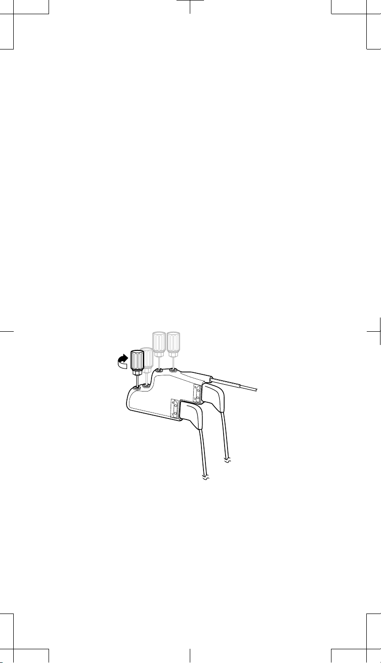
Tightening the pocket adaptor setscrews
1. Ensure all extension connector pins are fully seated in the adaptor
connector ports (Figure 7).
Figure 7. Ensure all extension connector pins are fully seated in the adaptor
and tighten all adaptor setscrews (total of two setscrews for the 1x4 pocket
adaptor; total of four setscrews for the 2x4 pocket adaptor).
2. Insert the torque wrench through the rubber grommet to engage the
setscrew.
# Caution: Be sure the torque wrench is fully inserted into the self-
sealing grommet. If the torque wrench is not fully inserted, the
16 English 74001, 74002 2009-07
2009-07
M933784A004 Rev A

Filename Date Time
UC200xxxxxx EN
4 x 8 inches (101 mm x 203 mm)
setscrew may be damaged, resulting in intermittent or loss of
stimulation.
3. Tighten the setscrew by turning the torque wrench clockwise until
resistance is felt.
4. Continue tightening until you hear clicking from the torque wrench. The
setscrews must touch the extension connector pins for a proper electrical
connection.
5. Repeat steps 2-4 for the remaining adaptor setscrews (total of two
setscrews for the 1x4 pocket adaptor; total of four setscrews for the 2x4
pocket adaptor).
Medtronic Confidential
ImplantManual.xsl -
LeadExtTemplate.fm
Template version: 04-22-2009
# Cautions:
▪ Ensure all adaptor setscrews are fully tightened.
Undertightening may result in insufficient electrical contact
within the connector block, which may cause intermittent
stimulation.
▪ Verify that each leaf of the self-sealing grommet is closed after
the torque wrench is withdrawn. If fluid leaks through a grommet
seal that is not fully closed, the patient may experience
shocking, burning, or irritation at the neurostimulator implant
location, or intermittent stimulation, or loss of stimulation.
Connecting the pocket adaptor to the neurostimulator
Use this procedur e when there is only one 1x4 pocket adaptor or one 2x4 pocket
adaptor being implanted.
If two 1x4 pocket adaptors are used, the instructions to connect to the
neurostimulator are in the "Two extensions (4 electrodes each) using two 1x4
pocket adaptors" procedure on page 13.
# Caution: Before connecting components, wipe off any body fluids and dry
all connections. Fluids in the connections may result in stimulation at the
connection site, intermittent stimulation, or loss of stimulation.
1. Wipe the adaptor connector pin with sterile gauze. If necessary, use
sterile USP water or a nonionic antibiotic solution.
2. Ensure the adaptor connector pin and the neurostimulator connector
block receptacles are dry and clean.
3. Slowly advance the adaptor connector pin into Socket I (front socket or
top socket) of the neurostimulator until seated fully within the connector
block (Figure 8a or b, depending on the model of the replacement
neurostimulator). Take care not to bend or kink the adaptor wire.
# Caution: Do not insert the adaptor connector pin into the
neurostimulator connector block if the setscrews are not sufficiently
retracted. If the setscrews are not retracted, the setscrews may
damage the adaptor and the adaptor will not be seated fully into the
connector block.
Notes:
During insertion, some resistance is typical.
▪
To retract the setscrews, insert the torque wrench into the self-sealing
▪
grommet and rotate the setscrews counterclockwise; however, do not
remove the setscrews from the connector block.
M933784A004 Rev A
74001, 74002 2009-07 English 17
2009-07
Filename Date Time
UC200xxxxxx EN
4 x 8 inches (101 mm x 203 mm)
(a)
Insert the adaptor connector pin into
Socket I (front socket):
Electrodes 0-3 for the 1x4 adaptor
Electrodes 0-7 for the 2x4 adaptor
Medtronic Confidential
ImplantManual.xsl -
LeadExtTemplate.fm
Template version: 04-22-2009
Insert the neurostimulator plug
into Socket II (back socket).
(b)
Figure 8. Insert the adaptor connector pin fully into neurostimulator Socket I.
4. Insert the neurostimulator plug into Socket II (back socket or bottom
socket) of the neurostimulator (Figure 8a or b, depending on the model of
the replacement neurostimulator).
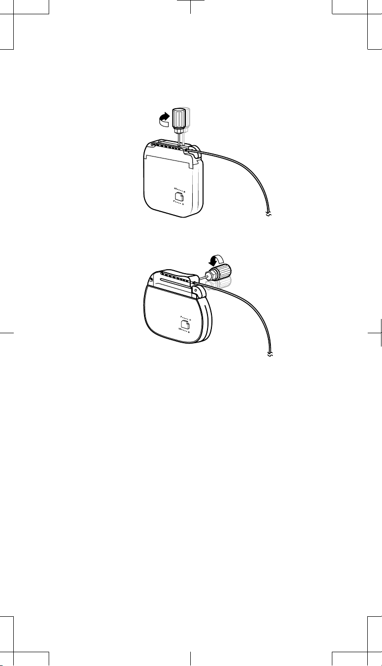
5. Fully insert the torque wrench (packaged with the neurostimulator) into
each self-sealing grommet of the neurostimulator connector block and
tighten each setscrew until you hear clicking from the torque wrench
(Figure 9a or b, depending on the model of the replacement
neurostimulator).
Insert the neurostimulator plug into Socket II.
Insert the adaptor connector pin into
Socket I (top socket):
Electrodes 0-3 for the 1x4 adaptor
Electrodes 0-7 for the 2x4 adaptor
Insert the neurostimulator plug
into Socket II (bottom socket).
# Cautions:
▪ Be sure the torque wrench is fully inserted into the self-sealing
grommet. If the torque wrench is not fully inserted, the setscrew
may be damaged, resulting in intermittent or loss of stimulation.
▪ Ensure all neurostimulator setscrews are fully tightened.
Undertightening may result in insufficient electrical contact
within the connector block, which may cause intermittent
stimulation.
▪ Verify that each leaf of the self-sealing grommet is closed after
the torque wrench is withdrawn. If fluid leaks through a grommet
seal that is not fully closed, the patient may experience shocking,
18 English 74001, 74002 2009-07
2009-07
M933784A004 Rev A
Filename Date Time
UC200xxxxxx EN
4 x 8 inches (101 mm x 203 mm)
burning, or irritation at the neurostimulator implant location, or
intermittent stimulation, or loss of stimulation.
Medtronic Confidential
ImplantManual.xsl -
LeadExtTemplate.fm
Template version: 04-22-2009
(a)
Tighten setscrews (2).
(b)
Figure 9. Tighten the neurostimulator setscrews in the self-sealing grommets.
Implanting the pocket adaptor with the neurostimulator
Notes:
Ensure all setscrews are tightened on the adaptor connector block and
▪
on the neurostimulator.
Refer to the neurostimulator implant manual for the proper subcutaneous
▪
pocket depth placement of the neurostimulator below the skin.
Implant the adaptor behind the neurostimulator so the neurostimulator is
▪
nearest the skin.
Proceed as follows:
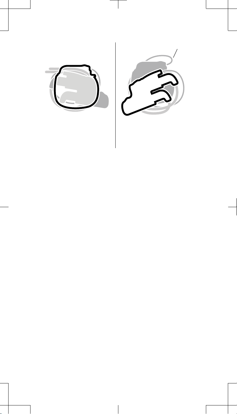
1. Place the pocket adaptor behind the neurostimulator. Coil the adaptor
wire and the excess extension wire behind the adaptor, ensuring there
are no sharp bends in any of the wires (Figure 10).
Tighten setscrews (2).
M933784A004 Rev A
74001, 74002 2009-07 English 19
2009-07
Filename Date Time
UC200xxxxxx EN
4 x 8 inches (101 mm x 203 mm)
Medtronic Confidential
ImplantManual.xsl -
LeadExtTemplate.fm
Template version: 04-22-2009
Sharp bend
There should be no sharp bends
for the adaptor and extension
wires.
The adaptor and extension wires
should not sharply bend.
YES NO
Figure 10. Ensure there are no sharp bends in any of the wires.
w Warning: Do not place any extension and adaptor wire between the
neurostimulator and the adaptor. Placement of the wires between
the two devices can damage the wire insulation and result in loss of
stimulation.
2. Place the neurostimulator, adaptor, and coiled wires (placed behind the
adaptor) into the subcutaneous pocket. The Medtronic logo on the
neurostimulator should face outward, away from muscle tissue.
w Warnings:
▪ Do not place the pocket adaptor connector block or the adaptor
wire between the skin and the neurostimulator (Figure 11).
Implanting the adaptor in this location can cause failures in
telemetry and/or recharge (for rechargeable neurostimulators).
Furthermore, placing the adaptor and wire in this location
nearest the skin m ay lead to damage to the adaptor and sever ing
of the adaptor wire in a future neurostimulator revision
procedure.
20 English 74001, 74002 2009-07
2009-07
M933784A004 Rev A
Filename Date Time
UC200xxxxxx EN
4 x 8 inches (101 mm x 203 mm)
Medtronic Confidential
ImplantManual.xsl -
LeadExtTemplate.fm
Template version: 04-22-2009
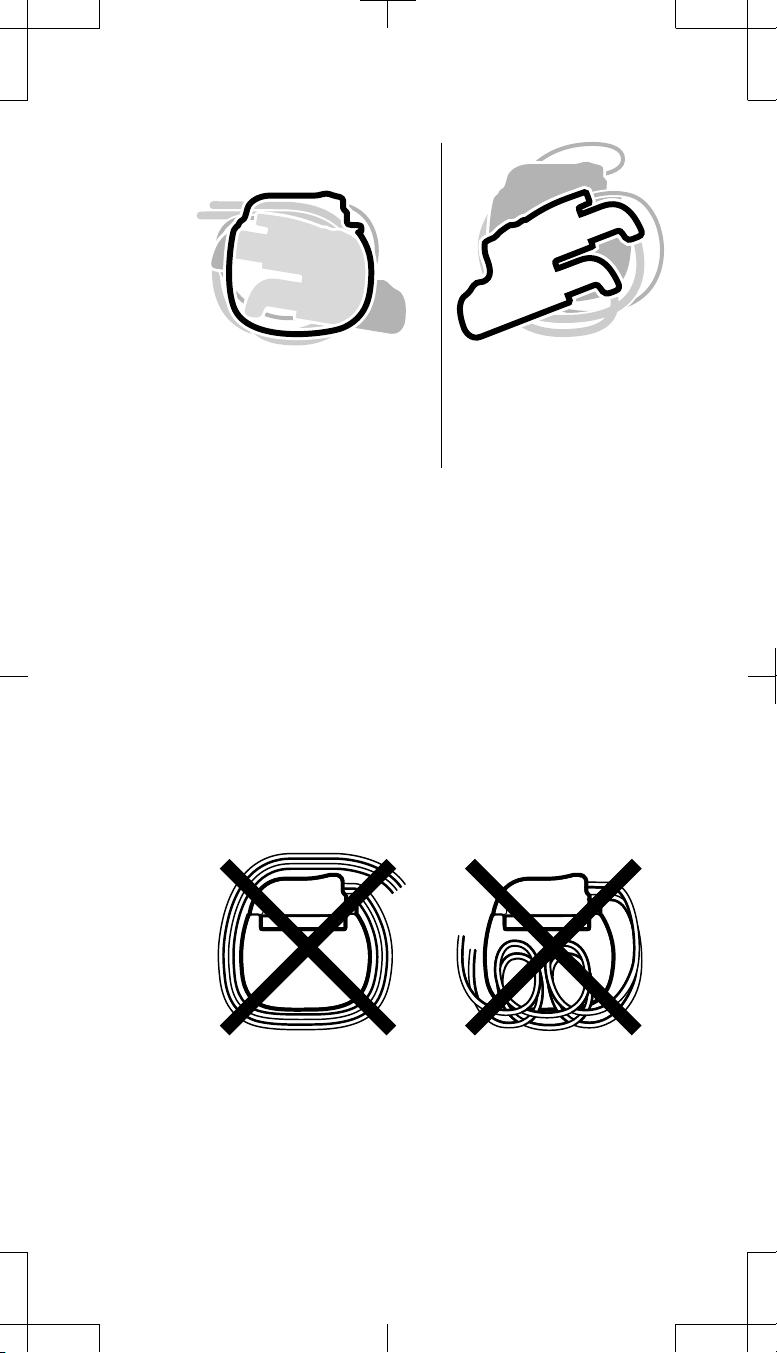
Place the adaptor behind the
neurostimulator. The neurostimulator
should be nearest the skin.
Never place the adaptor
between the skin and the
neurostimulator.
YES NO
Figure 11. Never place the adaptor between the skin and the
neurostimulator. Place the adaptor behind the neurostimulator.
▪ Do not place the pocket adaptor connector block in a medial,
lateral, superior, or inferior positions relative to the
neurostimulator. Placing the pocket adaptor connector block in
any one of these positions may cause skin erosion.
# Cautions:
▪ Position the neurostimulator with the Medtronic logo facing
outward. If implanted with the Medtronic logo facing inward,
rechargeable neurostimulators cannot be charged.
▪ Do not wrap or coil the extension or the adaptor wire around the
perimeter or in front of the neurostimulator (Figure 12).
Wrapping around the perimeter of the neurostimulator
increases the potential for the wires to slip between the
neurostimulator and the adaptor. Placing wires in front of the
neurostimulator increases the potential for kinking of the
extension and adaptor wires, for interference with telemetry
and/or recharge operation, and for damage during future
neurostimulator replacement surgery.
Figure 12. Do not wrap or coil the extension or adaptor wire around
3. Use the suture holes in the neurostimulator connector block to secure the
neurostimulator to the muscle fascia with nonabsorbable silk.
M933784A004 Rev A
the perimeter or in front of the neurostimulator.
74001, 74002 2009-07 English 21
2009-07
Filename Date Time
UC200xxxxxx EN
4 x 8 inches (101 mm x 203 mm)
Medtronic Confidential
ImplantManual.xsl -
LeadExtTemplate.fm
Template version: 04-22-2009
Checking system integrity
Refer to the neurostimulator manual for instructions. Use only the clinician
programmer to perform system integrity checks.
In addition, refer to the Model 8840/8870 N'Vision Clinician Programmer Guide
for detailed information to perform the following tasks to check the system
integrity for the system that now contains the pocket adaptor:
1. Interrogate the neurostimulator.
2. Program lead configuration. If needed , renumber the electrodes according
to Table 4 on page 22 of this manual.
3. Check electrode impedance.
Completing the implant procedure
1. Visually inspect that all implanted components are not nicked, cut, or
damaged in any way.
2. Close and dress all incisions.
3. Ensure that a patient control device is given to the patient.
4. Complete the device tracking and patient registration paperwork included
in the pocket adaptor package and return the documents to Medtronic.
Physician communication to patient if the pocket adaptor is removed
If the pocket adaptor is ever explanted, communicate to the patient at that time
that the pocket adaptor was intentionally removed.
At initial programming of the system
Indicate the use o f the pocket adaptor in the Note s field on the Patient Data
▪
screen of the Model 8840 N'Vision Clinician Programmer.
There may be differences between the explanted neurostimulator and the
▪
replacement neurostimulator. These include lead-electrode numbering
(see Table 4), amplitude settings, and impedance measurements.
Different impedances and an enhanced neurostimulator impedance
▪
measurement system can cause different impedance measurements from
the explanted neurostimulator.
See Table 4 for neurostimulator socket and electrode numbering. If
▪
electrodes require renumbering, use the Lead Configuration screen of the
clinician programmer.
Table 4. Neurostimulator sockets and electrode numbering
Pocket
adaptor
One 2x4
One 1x4
Neurostimulator socket and
corresponding electrodes
If Socket I is used, the default electrode
▪
numbering is as follows and requires
no renumbering:
Lead I: 0-3
–
Lead II: 4-7
–
If Socket II is used, the electrodes
▪
require renumbering to the following:
Lead I: 8-11
–
Lead II: 12-15
–
If Socket I is used, the default electrode
▪
numbering is 0-3 and requires no
renumbering.
If Socket II is used, the electrodes
▪
require renumbering to 8-11.
Lead
Configuration
2x4
1x4
a,b
22 English 74001, 74002 2009-07
2009-07
M933784A004 Rev A
Filename Date Time
UC200xxxxxx EN
4 x 8 inches (101 mm x 203 mm)
Medtronic Confidential
ImplantManual.xsl -
LeadExtTemplate.fm
Template version: 04-22-2009
Table 4. Neurostimulator sockets and electrode numbering (continued)
Pocket
adaptor
Two 1x4s
Neurostimulator socket and
corresponding electrodes
Socket I default electrode numbering
▪
for Lead I is 0-3 and requires no
Configuration
renumbering.
Socket II electrodes for Lead II require
▪
renumbering to 8-11.
a
This is the configuration to select in the Lead Configuration screen of the clinician
programmer.
b
If additional leads are added to the system, the lead configuration will be different from what
is given in this column.
Lead
2x4
a,b
M933784A004 Rev A
74001, 74002 2009-07 English 23
2009-07

Filename Date Time
UC200xxxxxx EN
4 x 8 inches (101 mm x 203 mm)
Medtronic Confidential
LeadExtTemplate.fm
Template version: 04-22-2009
Objaśnienie symboli zamieszczonych na etykietach
produktu lub opakowania
Stosowne symbole można znaleźć na konkretnych produktach.
Otwierać tutaj
Produkt do jednorazowego zastosowania
Produkt sterylizowany tlenkiem etylenu
STERILE
EO
Uwaga! Należy zapoznać się z dołączoną dokumentacją.
Data produkcji
Data ważności
Dopuszczalna temperatura
ImplantManual.xsl -
LOT
0123
Numer partii produkcyjnej
Conformité Européenne (Zgodność z normami Unii
Europejskiej). Symbol oznacza, że urządzenie spełnia
wszystkie wymogi dyrektywy europejskiej AIMD 90/385/EEC.
Dotyczy tylko odbiorców w USA
24 Polski 74001, 74002
2009-07
M933784A004 Rev A

Filename Date Time
UC200xxxxxx EN
4 x 8 inches (101 mm x 203 mm)
Medtronic Confidential
ImplantManual.xsl -
LeadExtTemplate.fm
Template version: 04-22-2009
Medtronic®, N'Vision®, PrimeADVANCED®, Restore®, RestoreADVANCED®,
RestorePRIME
®
i RestoreULTRA® są zastrzeżonymi znakami towarowymi
firmy Medtronic, Inc.
M933784A004 Rev A
74001, 74002 Polski 25
2009-07
Filename Date Time
UC200xxxxxx EN
4 x 8 inches (101 mm x 203 mm)
Medtronic Confidential
Template version: 04-22-2009
Spis treści
Opis urządzenia 27
Zawartość opakowania 27
Dane techniczne urządzenia 27
Zgodne przedłużacze czterobiegunowe 31
Zgodne neurostymulatory 31
Kwestie istotne przed implantacją 32
Instrukcja użytkowania 33
Układanie pacjenta 33
Ponowne otwieranie loży neurostymulatora 33
Wycofywanie śrub dociskowych 34
Odłączanie przedłużaczy od eksplantowanego neurostymulatora i łączenie
z łącznikiem loży 34
Jeden przedłużacz (4 elektrody) z wykorzystaniem łącznika loży
1x4 34
Jeden przedłużacz (4 elektrody) z wykorzystaniem łącznika loży
2x4 34
Dwa przedłużacze lub przedłużacz rozwidlony (8 połączonych elektrod)
z wykorzystaniem łącznika loży 2x4 35
Dwa przedłużacze (4 elektrody w każdym) z wykorzystaniem dwóch
łączników loży 1x4 37
Dokręcanie śrub dociskowych łącznika loży 40
Podłączanie łącznika loży do neurostymulatora 41
Implantacja łącznika loży z neurostymulatorem 44
Sprawdzenie integralności układu 47
Zakończenie procedury implantacji 47
Komunikacja lekarza z pacjentem w przypadku usunię
loży 47
Przy początkowym programowaniu systemu 47
cia łącznika
ImplantManual.xsl -
LeadExtTemplate.fm
Wskazania i inne podobne informacje znajdują się na karcie wskazań.
Informacje dotyczące przeciwwskazań, ostrzeżeń, środków ostrożności,
zdarzeń niepożądanych, indywidualizacji leczenia, doboru pacjentów,
zastosowania w odniesieniu do poszczególnych grup pacjentów,
ponownej steryli zacji oraz utylizacji elementów znajdu ją się w broszurach
przeznaczonych dla lekarzy zlecających.
Informacje na temat wyboru neurostymulatora i obliczania czasu
funkcjonowania baterii, a także dane techniczne konkretnego modelu
neurostymulatora znajdują się w instrukcji użytkowania dołączonej do
karty oprogramowania i opatrzonej odpowiednim tytułem.
Informacje na temat wyników badań klinicznych dotyczących
systemu neurostymulacji oraz indywidualizacji leczenia znajdują się w
broszurze dołączonej do neurostymulatora.
26 Polski 74001, 74002
2009-07
M933784A004 Rev A
Filename Date Time
UC200xxxxxx EN
4 x 8 inches (101 mm x 203 mm)
Medtronic Confidential
ImplantManual.xsl -
LeadExtTemplate.fm
Template version: 04-22-2009
Opis urządzenia
Łączniki loży model 74001 (1x4) i 74002 (2x4) firmy Medtronic można stosować
jako część systemu stymulacji rdzenia kręgowego w leczeniu bólu.
Łącznik loży jest przeznaczony do implantowania z nowym neurostymulatorem
w tej samej loży, która była używana w przypadku eksplantowanego
neurostymulatora. Implantacja w tej samej loży neurostymulatora umożliwia
przeprowadzenie zabiegu chirurgicznego z jednego nacięcia.
Zawartość opakowania
Łącznik loży
▪
Ośmiobiegunowy wbudowany wtyk do neurostymulatora
▪
Klucz dynamometryczny
▪
Dokumentacja produktu
▪
Karta gwarancyjna
▪
Formularz rejestracyjny
▪
Dane techniczne urządzenia
Łącznik loży posiada złącze wejściowe 1x8 na końcu proksymalnym i gniazda
złączy na końcu dystalnym, przeznaczone do połączenia z przedłużaczami.
Końcówkę dystalną łącznika loży 1x4 łączy się z przedłużaczem
czterobiegunowym firmy Medtronic. Końcówkę dystalną łącznika loży 2x4 łączy
się z dwoma przedłużaczami czterobiegunowymi firmy Medtronic lub jednym
przedłużaczem rozwidlonym. Końcówkę proksymalną podłącza się do
neurostymulatora.
Informacje na temat zgodności przedłużacza i neurostymulatora z łącznikiem
loży można znaleźć w częściach "Zgodne przedłużacze czterobiegunowe" i
"Zgodne neurostymulatory", strona 31.
Śruby dociskowe (2)
Blok złącza
Koniec dystalny
Rysunek 1. Łącznik loży model 74001 (1x4).
Odstęp między stykami
Przewód łącznika
Gniazdo
złącza
Koniec proksymalny
74001, 74002 Polski 27
M933784A004 Rev A
2009-07

Filename Date Time
UC200xxxxxx EN
4 x 8 inches (101 mm x 203 mm)
Medtronic Confidential
ImplantManual.xsl -
LeadExtTemplate.fm
Template version: 04-22-2009
Śruby dociskowe (4)
Blok złącza
Koniec dystalny
Rysunek 2. Łącznik loży model 74002 (2x4).
Odstęp między stykami
Przewód łącznika
Koniec proksymalny
Gniazdo złącza
dla elektrod 0–3
Gniazdo złącza
dla elektrod 4–7
28 Polski 74001, 74002
2009-07
M933784A004 Rev A
 Loading...