


INSYNC SENTRY®7299
Dual chamber implantable cardioverter defibrillator with
cardiac resynchronization therapy including sequential
biventricular pacing and OptiVol®Fluid Monitoring
Reference Manual
Caution: Federal Law (USA) restricts this device to sale
by or on the order of a physician.


INSYNC SENTRY®7299
Reference Manual
A guide to the operation and programming of the Model 7299
InSync Sentry dual chamber implantable cardioverter defibrillator with
cardiac resynchronization therapy including sequential biventricular pacing
and OptiVol
®
Fluid Monitoring

The following are trademarks of Medtronic:
Active Can, Cardiac Compass, Checklist, Flashback, InSync, InSync II Marquis,
InSync Maximo, InSync Sentry, Leadless, Marker Channel, Marquis, Maximo,
Medtronic, Medtronic CareLink, OptiVol, PR Logic, Patient Alert, Quick Look,
QuickLink, T-Shock

Contents
Introduction 11
Part I Quick overview 13
1 Quick reference 15
1.1 Physical characteristics 17
1.2 Magnet application 18
1.3 Projected longevity 19
1.4 Replacement indicators 21
1.5 Typical charge times 21
1.6 High-voltage therapy energy 22
1.7 Stored data and diagnostics 23
1.8 New and enhanced features 24
2 The InSync Sentry system 27
2.1 System overview 29
2.2 Indications and usage 33
2.3 Contraindications 33
2.4 Patient screening 33
3 Emergency therapy 35
3.1 Delivering emergency therapies 37
3.2 Delivering an emergency defibrillation therapy 38
3.3 Delivering an emergency cardioversion therapy 39
3.4 Delivering emergency fixed burst pacing 39
3.5 Enabling emergency VVI pacing 40
Part II Device implant and patient follow-up
procedures 43
4 Implanting the device 45
4.1 Implant overview 47
4.2 Preparing for an implant 47
4.3 Replacing a device 49
4.4 Surgical approach 50
4.5 Sensing and pacing measurements 54
4.6 Connecting the leads to the device 54
INSYNC SENTRY®7299 Reference Manual

6
Contents
4.7 Testing defibrillation operation and effectiveness 58
4.8 Positioning and securing the device 61
4.9 Completing the implant procedure 61
5 Conducting a patient follow-up session 63
5.1 Patient follow-up guidelines 65
5.2 Verifying the status of the implanted system 65
5.3 Verifying effective cardiac resynchronization
therapy 66
5.4 Verifying effective basic pacing 67
5.5 Verifying accurate detection and appropriate therapy for
ventricular tachyarrhythmias 68
Part III Configuring the device for the patient 71
6 Detecting tachyarrhythmias 73
6.1 Detection overview 75
6.2 Setting up sensing 78
6.3 Detecting VF episodes 83
6.4 Detecting VT episodes 86
6.5 Detecting FVT episodes 92
6.6 Detecting tachyarrhythmia episodes with Combined
Count 97
6.7 Monitoring episodes for termination or
redetection 99
6.8 Enhancing detection with PR Logic criteria 103
6.9 Enhancing VT detection with the Stability
criterion 111
6.10 Detecting double tachycardias 113
6.11 Detecting prolonged tachyarrhythmias with High Rate
Timeout 114
7 Treating tachyarrhythmia episodes 117
7.1 Treating VF with defibrillation 119
7.2 Treating VT and FVT with antitachycardia
pacing 128
7.3 Treating VT and FVT with cardioversion 137
7.4 Optimizing therapy with Smart Mode and Progressive
Episode Therapies 146
8 Treating ventricular dyssynchrony and
bradycardia 151
8.1 Providing basic pacing therapy 153
INSYNC SENTRY®7299 Reference Manual

Contents
8.2 Dual chamber pacing 161
8.3 Single chamber pacing 172
8.4 Promoting continuous CRT delivery 176
8.5 Rate adjustments to optimize cardiac output 186
8.6 Managing atrial tracking to optimize A-V
synchrony 198
8.7 Providing Ventricular Safety Pacing 210
9 Optimizing charge time and device longevity 215
9.1 Optimizing charge time 217
9.2 Optimizing device longevity 219
Part IV Evaluating and managing patient treatment 221
10 Using the programmer 223
10.1 Setting up and using the programmer 225
10.2 Display screen features 226
10.3 Viewing and programming device parameters 231
10.4 Starting and ending patient sessions 235
10.5 Viewing live waveform traces 238
10.6 Recording live waveform strips 245
10.7 Transferring, saving, and retrieving device data 247
10.8 Printing reports 255
11 Using system evaluation tools 261
11.1 A summary of system evaluation tools 263
11.2 Taking a quick look at device activity 264
11.3 Using the Patient Alert feature 265
11.4 Streamlining follow-ups with Checklist 273
12 Setting up and viewing collected data 277
12.1 A summary of data collection 279
12.2 Viewing battery and lead status data 280
12.3 Printing rate histograms 286
12.4 Viewing the Heart Failure Management report 289
12.5 Viewing clinical trends in the Cardiac Compass
report 293
12.6 Viewing the episode and therapy efficacy
counters 302
12.7 Viewing episode data 305
12.8 Viewing Flashback Memory 314
12.9 Setting up data collection 316
7
INSYNC SENTRY®7299 Reference Manual

8
Contents
12.10 Viewing and entering patient information 322
12.11 Automatic device status monitoring 325
13 Testing the system 329
13.1 Testing overview 331
13.2 Evaluating the underlying rhythm 331
13.3 Measuring pacing thresholds 332
13.4 Measuring lead impedance 335
13.5 Measuring EGM amplitude 337
13.6 Testing the device capacitors 339
14 Conducting Electrophysiologic Studies 341
14.1 EP Study overview 343
14.2 Inducing VF with T-Shock 344
14.3 Inducing VF with 50 Hz Burst 348
14.4 Inducing an arrhythmia with Manual Burst 350
14.5 Inducing an arrhythmia with PES 352
14.6 Delivering a manual therapy 355
15 Solving system problems 359
15.1 Overview 361
15.2 Solving cardiac resynchronization therapy
problems 361
15.3 Solving sensing problems 362
15.4 Solving tachyarrhythmia detection problems 364
15.5 Solving tachyarrhythmia therapy problems 365
15.6 Solving bradycardia pacing problems 366
15.7 Responding to device status indicators 367
Appendices 369
A Warnings and precautions 371
A.1 General warnings 373
A.2 Handling and storage instructions 373
A.3 Device operation 374
A.4 Lead evaluation and lead connection 376
A.5 Follow-up testing 378
A.6 Explant and disposal 378
A.7 Medical therapy hazards 378
A.8 Home and occupational environments 381
B Device parameters 383
B.1 Emergency settings 385
INSYNC SENTRY®7299 Reference Manual

C Device programming recommendations 403
Glossary 411
Index 419
Contents
B.2 Detection parameters 386
B.3 Therapy parameters 387
B.4 Pacing parameters 389
B.5 System maintenance parameters 392
B.6 Data collection parameters 394
B.7 System test and EP study parameters 395
B.8 Fixed parameters 398
B.9 Patient information parameters 399
B.10 Programmer symbols 400
B.11 Parameter interlocks 402
C.1 Device programming recommendations 405
C.2 V-V Delay programming recommendations 407
9
INSYNC SENTRY®7299 Reference Manual


Introduction
Using this manual
Before implanting the device, it is strongly recommended that you:
Manual conventions
Throughout this document, the word “device” refers to the
implanted InSync Sentry device.
Introduction
Refer to the product literature packaged with the device for
•
information about prescribing the device.
Thoroughly read this manual and the technical manuals for
•
the leads and the implant tools used with the device.
Discuss the procedure and the device system with the
•
patient and any other interested parties, and provide them
with any patient information packaged with the device.
11
Technical support
References
The
nominal value for that parameter.
On-screen buttons are shown with the name of the button
surrounded by brackets: [Button Name].
Medtronic employs highly trained representatives and engineers
located throughout the world to serve you and, upon request,
to provide training to qualified hospital personnel in the use of
Medtronic products.
In addition, Medtronic maintains a professional staff of consultants
to provide technical consultation to product users.
For more information, contact your local Medtronic representative,
or call or write Medtronic at the appropriate address or telephone
number listed on the back cover.
The primary reference for background information is Zacouto FI,
Guize LJ. Fundamentals of Orthorhythmic Pacing. In: Luderitz B,
ed.
Springer-Verlag; 1976: 212-218.
symbol in parameter tables indicates the Medtronic
Cardiac Pacing Diagnostic and Therapeutic Tools. New York:
INSYNC SENTRY®7299 Reference Manual

12
Introduction
Notice
See these additional references for more background information:
Estes M, Manolis AS, Wang P, Eds.
•
Cardioverter-Defibrillators
Inc. 1994.
Kroll MW, Lehmann MH, Eds.
•
Cardioverter-Defibrillator Therapy: The Engineering-Clinical
Interface
Singer I, Ed.
•
NY: Futura Publishing Co. 1994.
Singer I, Barold SS, Camm AJ, Eds.
•
Therapy of Arrhythmias for the 21st Century: The State of
the Art
Software is provided as an informational tool for the end user.
The user is responsible for accurate input of patient information
into the software. Medtronic makes no representation as
to the accuracy or completeness of the data input into the
software. Medtronic SHALL NOT BE LIABLE FOR ANY DIRECT,
INDIRECT, INCIDENTAL OR CONSEQUENTIAL DAMAGES TO
ANY THIRD PARTY WHICH RESULT FROM THE USE OF THE
INFORMATION PROVIDED IN THE SOFTWARE.
. Norwell, MA: Kluwer Academic Publishers 1996.
Implantable Cardioverter-Defibrillator. Armonk,
. Armonk, NY: Futura Publishing Co. 1998.
. New York, NY: Marcel Dekker,
Implantable
Implantable
Nonpharmacological
INSYNC SENTRY®7299 Reference Manual

Quick overview
Part I


1Quick reference
1.1 Physical characteristics 17
1.2 Magnet application 18
1.3 Projected longevity 19
1.4 Replacement indicators 21
1.5 Typical charge times 21
1.6 High-voltage therapy energy 22
1.7 Stored data and diagnostics 23
1.8 New and enhanced features 24
1


1.1 Physical characteristics
Table 1. Device physical characteristics
Volume
Mass
H x W x D
Surface area of device
can
Radiopaque ID
Materials in contact with
human tissue
Battery Lithium silver vanadium oxide
Connectors Two IS-1 connectors for pacing and
a
Measurements are nominal values based on CAD (computer aided design)
model measurements and are rounded to the nearest unit.
b
Volume with connector holes unplugged.
c
Grommets may protrude slightly beyond the can surface.
d
Engineering series number follows the radiopaque code.
e
These materials have been successfully tested and verified for biocompatibility.
The device does not produce an injurious temperature in the surrounding tissue.
c
d
e
1Quick reference
Physical characteristics
a
3 b
40 cm
78 g
73 mm x 51 mm x 15 mm
2
67 cm
PRK
Titanium / polyurethane /silicone rubber
/ silicone adhesive
sensing, one IS-1 connector for
pacing, two DF-1 connectors for
high-voltage therapy, Active Can
electrode (programmable)
17
Table 2. Lead connections
Device port Connector type Software name
SVC (HVX) DF-1 SVC
RV (HVB) DF-1 RVcoil
Can
—
Can
RV IS-1 bipolar RVtip and RVring
LV IS-1 bipolar LVtip and LVring
A IS-1 bipolar Atip and Aring
INSYNC SENTRY®7299 Reference Manual
18
2
5
4
6
3
1
Chapter 1
Magnet application
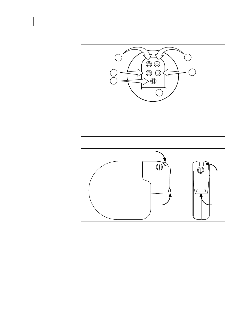
Figure 1. Lead connections
1 SVC (HVX)
2 RV (HVB)
3 Can (HVA)
4 LV
5 RV
6 A
Figure 2. Suture holes
1.2 Magnet application
Bringing a magnet close to the device triggers changes in device
operation as shown in Table 3. When the magnet is removed, the
device returns to its programmed operations.
For information on demonstrating Patient Alert tones to the
patient, see Section 11.3.4, “Instructing the patient”, page 271.
INSYNC SENTRY®7299 Reference Manual

Table 3. Effects of magnet application on the device
Pacing mode as programmed
Pacing rate and interval as programmed
VF, VT, and FVT detection suspended
Patient Alert audible tones
(20 s or less)
a
Rate response adjustments are suspended while a Patient Alert tone sounds.
b
Detection resumes if telemetry is established and the application software is
running, or detection resumes after the application software has started.
c
Or “VF Detection/Therapy Off” is the only alert enabled.
1.3 Projected longevity
Longevity estimates are based on accelerated battery discharge
data and device modeling with EGM pre-storage off (see Table 4).
The following table displays projected longevity in years with
pacing outputs programmed to the specified amplitude and 0.4 ms
pulse width, DDD mode, 100% biventricular pacing, specified
percentage of atrial pacing at 60 ppm with the remainder at
70 ppm atrial tracking, and semiannual full-energy charges.
1Quick reference
Projected longevity
a
b
high/low dual tone (high urgency
•
alert occurred)
on/off intermittent tone (lower
•
urgency alert occurred)
continuous test tone (no alert
•
occurred)
no tone (alerts are disabled)
•
19
c
1
Table 4. Projected longevity in years
Amplitudes:
A/RV; LV
2.5 V; 3.0 V
% atrial
pacing
pacing
impedance
0% 5.8 6.2 6.5
500 Ù
700 Ù
pacing
impedance
900 Ù
pacing
impedance
25% 5.6 6.0 6.4
50%
100% 5.2
3.0 V; 4.0 V
1
Semiannual full-energy charges may include therapy shocks or capacitor
formations. Additional full-energy charges due to therapy shocks, device
testing, or capacitor formation reduces device longevity by approximately 26
days (0.07 years). Additional 30 J charges due to therapy shocks or device
testing reduces device longevity by approximately 22 days (0.06 years).
0% 4.9
5.5
6.0 6.3
5.7
5.5
INSYNC SENTRY®7299 Reference Manual
6.1
5.8

20
Chapter 1
Projected longevity
Table 4. Projected longevity in years (continued)
Amplitudes:
A/RV; LV
The longevity of the ICD is dependent on several factors. The
following factors result in decreased longevity:
an increase in pacing rate, pacing amplitude, or pulse
•
width; the ratio of paced to sensed events; or the charging
frequency
a decrease in pacing impedance
•
using the pre-onset EGM storage feature or Holter telemetry
•
Considerations for using EGM pre-storage – When the EGM
pre-storage feature is programmed to Off, the device starts
to store EGM following the third tachyarrhythmia event and
also provides up to 20 s of information before the onset of the
tachyarrhythmia, including this information:
AA and VV intervals
•
Marker Channel
•
Interval Plot Flashback
•
% atrial
pacing
25% 4.8 5.3
50% 4.6 5.2 5.6
100% 4.4 5.0 5.4
500 Ù
pacing
impedance
700 Ù
pacing
impedance
900 Ù
pacing
impedance
5.7
When the EGM pre-storage feature is programmed to On, the
device also collects up to 20 s of EGM information before the
onset of the arrhythmia.
In a patient who uniformly repeats the same onset mechanisms,
the greatest clinical benefit of pre-onset EGM storage is achieved
after a few episodes are captured. To maximize the effectiveness
of the EGM pre-storage feature and optimize device longevity,
consider these programming options:
Turn pre-storage to On to capture possible changes in the
•
onset mechanism following significant clinical adjustments,
for example, device implant, medication changes, and
surgical procedures.
Turn pre-storage to Off once you have successfully captured
•
the information of interest.
INSYNC SENTRY®7299 Reference Manual

1.4 Replacement indicators
Battery voltage and messages about replacement status appear
on the programmer display and on printed reports. The Elective
Replacement Indicator (ERI) and the End of Life (EOL) conditions
are listed in Table 5.
Table 5. Replacement indicators
Elective Replacement (ERI) ≤ 2.62 V
End of Life (EOL) 3 months after ERI
ERI date – The Quick Look and Battery and Lead Measurements
screens display the date when the battery reached ERI.
Temporary voltage decrease – The battery voltage temporarily
decreases following a high-voltage charge. If a battery
measurement is taken immediately after a high-voltage charge,
the ERI or EOL indicator may be displayed. However, this is a
temporary status that will return to normal when the battery has
recovered from the charge.
EOL indication – If the programmer indicates that the device is
at EOL, replace the device immediately.
1Quick reference
Replacement indicators
21
Post-ERI conditions – EOL device status is defined as 3 months
following an ERI indication assuming the following post-ERI
conditions: 0% DDD atrial pacing; 100% DDD RV and LV pacing
at 60 ppm; 3 V atrial and RV pacing amplitude; 4 V LV pacing
amplitude; 0.4 ms pulse width; 500 Ù pacing load; and six 35 J
charges. EOL may be indicated before the end of 3 months if the
device exceeds these conditions.
1.5 Typical charge times
The most recent capacitor charge time appears on the
programmer display and on printed reports and can be evaluated
using the Charge/Dump test (see Table 6).
Table 6. Typical
At Beginning of Life (BOL)
At Elective Replacement (ERI)
a
These charge times are typical when the capacitors are fully formed.
a
full-energy charge times
7.1 s
9.0 s
INSYNC SENTRY®7299 Reference Manual

22
Chapter 1
High-voltage therapy energy
1.6 High-voltage therapy energy
The stored energy of the device is derived from the peak
capacitor voltage and is always greater than the energy delivered
by the device. Table 7 compares the programmed energy
levels delivered by the device to the energy levels stored in the
capacitors before delivery.
Table 7. Comparison of delivered (programmed) and stored energy levels
Energy ( J) Energy ( J)
a
Delivered
Programmed Stored
a
Energy delivered at connector block into a 75 Ù load.
b
Energy stored at end of charge on capacitor.
c
Typical charge time at Beginning of Life (BOL) with fully formed capacitors, rounded to the nearest tenth of
a second.
/
b
Charge
Timec( s)
Delivereda/
Programmed Stored
b
35 39 7.1 10 12 2.0
32 37 6.5 9 10.5 1.8
30 34 6.1 8 9.3 1.6
28 32
5.7 7
8.2 1.4
26 30 5.2 6 7.1 1.2
25 29 5.0
5
5.9 1.0
24 27 4.8 4 4.8 0.8
22 25 4.4 3 3.6 0.6
20 23 4.0 2 2.4 0.4
18 21 3.6 1.8 2.2 0.4
16 19 3.2 1.6 2.0 0.3
15 17 3.0 1.4 1.7 0.3
14 16 2.8 1.2 1.5 0.2
13 15 2.6 1.0 1.2 0.2
12 14 2.4 0.8 1.0 0.2
11 13 2.2 0.6 0.8 0.1
0.4 0.5 0.1
Charge
Timec( s)
INSYNC SENTRY®7299 Reference Manual

1Quick reference
Stored data and diagnostics
1.7 Stored data and diagnostics
Table 8. Stored data and diagnostics
Episode data
Tachy episodes 150 VF/VT/FVT episodes: intervals, text, EGM
EGM capacity for tachy episodes 14 min of dual-channel EGM or 23.5 min of
SVT/NST episodes 50 SVT/NST episodes: intervals, text, EGM (the device
EGM capacity for SVT/NST
episodes
EGM sources 14 options: atrial/ RV / LV / far-field
EGM options Store before onset; Store during charging
Flashback memory 2000 intervals (containing both A-A and V-V): before
Mode Switch episodes 53 Mode Switch episodes (fastest, longest, first and 50
Ventricular sensing episodes 9 ventricular sensing episodes (longest, first, and 7
Counter data
Detection counters Lifetime total, since cleared, and since last session
Episode counters Episodes:
Therapy efficacy counters Counts for each VF, FVT, VT Therapy:
single-channel EGM
does not usually store detailed episode records for NST
episodes)
2 min of dual-channel EGM or 3.6 min of single-channel
EGM
latest VF, before latest VT, and before interrogation
latest): episode text
latest): intervals, markers, and counter data text
VF, FVT, and VT
•
Atrial Fibrillation/Atrial Flutter episodes
•
Sinus Tach episodes
•
Other 1:1 SVT episodes
•
NST episodes
•
Mode Switch episodes
•
Percentage pacing:
AS-VS, AS-VP, AP-VS, AP-VP percentages
•
Additional counters:
Single PVCs and PVC runs
•
Rate stabilization pulses and runs
•
Delivered
•
Successful
•
Unsuccessful
•
Intervention (manually aborted)
•
Total number of aborted shocks
23
INSYNC SENTRY®7299 Reference Manual

24
Chapter 1
New and enhanced features
Table 8. Stored data and diagnostics (continued)
Other stored data
Patient Alert — System events Up to 10 log entries: text and date for the first time an
Battery and lead measurements Battery voltage, last capacitor formation, last charge,
Lead performance trends 14 days of daily measurements plus 80 weeks of weekly
Rate Histograms
Cardiac Compass trends 14 months of daily measurements:
alert is triggered between interrogations
lead impedance, EGM amplitude measurements, last
high-voltage therapy, and sensing integrity counter
minimum and maximum measurements:
lead impedance: atrial pacing, RV pacing, LV
•
pacing, defibrillation pathway, and SVC lead (if
used)
atrial EGM amplitude (P-waves)
•
Atrial rate
•
Ventricular rate
•
Ventricular rate during AT/AF
•
VT and VF episodes per day
•
one or more high-voltage therapy delivered
•
ventricular rate during VT or VF
•
episodes of non-sustained tachycardia per day
•
total daily time in AT/AF
•
ventricular rate during AT/AF
•
percent pacing per day
•
average day and night ventricular heart rate
•
patient activity
•
heart rate variability
•
thoracic impedance
•
accumulated differences between the daily and
•
reference thoracic impedance (OptiVol fluid index)
1.8 New and enhanced features
The following features are new or changed from the 7289 InSync
II Marquis ICD.
1.8.1 Patient management
OptiVol Fluid Monitoring – The OptiVol Fluid Monitoring
feature is designed to assist the physician in assessing the
INSYNC SENTRY®7299 Reference Manual

patient’s thoracic fluid status. When the device determines that
the patient’s thoracic fluid status has exceeded a programmed
threshold, an observation is displayed on the Quick Look screen
and Heart Failure Management Report at the next interrogation.
The OptiVol Fluid Monitoring feature is an additional source
of information for patient management and does not replace
assessments that are part of standard clinical practice.
OptiVol Fluid Trends – There are 2 OptiVol Fluid Trends:
The Thoracic impedance trend plots thoracic impedance for
•
up to 14 months. The Daily thoracic impedance is measured
between the RVcoil and Can.
The OptiVol fluid index trend plots the accumulated
•
differences between the daily and reference thoracic
impedance. Thoracic fluid accumulation may exist when the
OptiVol fluid index is greater than the OptiVol threshold.
The OptiVol Fluid Trends are included in the Cardiac Compass
and Heart Failure Management reports. For more information on
each trend, see Section 12.5.2.
1.8.2 Tachyarrhythmia therapy
1Quick reference
New and enhanced features
25
Output – The InSync Sentry CRT-D has a maximum delivered
energy of 35 J.
1.8.3 Cardiac resynchronization therapy
Sequential biventricular pacing – The ventricular sequence
and V-V pace delay are programmable to support improved
hemodynamics.
Pacing outputs for RV and LV are independently programmable.
INSYNC SENTRY®7299 Reference Manual


2The InSync Sentry system
2.1 System overview 29
2.2 Indications and usage 33
2.3 Contraindications 33
2.4 Patient screening 33
2


2.1 System overview
The Model 7299 InSync Sentry dual chamber implantable
cardioverter defibrillator with cardiac resynchronization therapy
(CRT-D) including sequential biventricular pacing and OptiVol
Fluid Monitoring is an implantable medical device system that
includes 3 major components:
CRT-D device
•
leads
•
programmer, software, and accessories
•
Each of these components is described in detail below.
Device – The device senses the electrical activity of the patient’s
heart using the sensing electrodes of the implanted atrial and
right ventricular leads. It then analyzes the heart rhythm based
on selectable sensing and detection parameters. The device
provides the following functions:
simultaneous or sequential biventricular pacing for cardiac
•
resynchronization
automatic detection and treatment of ventricular
•
tachyarrhythmias (ventricular fibrillation, ventricular
tachycardia, and fast ventricular tachycardia) with
defibrillation, cardioversion, and antitachycardia pacing
therapies
single or dual chamber pacing for patients requiring rate
•
support
diagnostics and monitors that evaluate the system and assist
•
in patient care
2The InSync Sentry system
System overview
®
29
Leads – The device can be used with transvenous or epicardial
defibrillation leads. The lead system should consist of bipolar or
paired unipolar pacing/sensing leads in the right atrium and right
ventricle of the heart, a pacing lead for the left ventricle, and 1 or
2 high-voltage cardioversion/defibrillation electrodes. In addition
to the lead system, the Active Can feature enables the device to
act as one of the high-voltage electrodes. The device delivers
pacing and cardiac resynchronization therapy via the atrial (A),
right ventricular (RV), and left ventricular (LV) leads. The device
senses using the atrial and RV leads. Cardioversion/defibrillation
therapy is delivered with 2 lead-based high-voltage electrodes, or
with the Active Can defibrillation electrode and 1 or 2 lead-based
high-voltage electrodes.
INSYNC SENTRY®7299 Reference Manual

30
Chapter 2
System overview
The OptiVol Fluid Monitoring feature may be adversely affected
by the use of an epicardial defibrillation lead instead of an RVcoil.
Prior to implanting the left ventricular pacing lead, thoroughly
read the associated left ventricular lead technical manual.
Programmer and software – The Medtronic CareLink
Programmer, Model 2090,1and Model 9998 software application
allow you to perform the following functions:
configure the cardiac resynchronization, arrhythmia detection
•
and therapy, and bradycardia features for your patient
perform electrophysiological studies and system tests
•
monitor, display, or print patient cardiac activity information
•
Network connectivity and data exchange – The system
supports network connectivity and the exchange of data between
the Medtronic Carelink 2090 programmer and the Medtronic
Paceart data management system using the SessionSync feature.
Concurrent Analyzer – The system supports the use of the
Medtronic 2290 Analyzer, which allows you to have a device
session and an analyzer session running at the same time,
quickly switch from one to the other without having to end or
restart sessions, and export data from the analyzer to the device
software application.
Remote View – The system supports Remote View, which allows
you to use a personal computer in your office or elsewhere to
view the screen displays from a Medtronic Carelink programmer
in a clinic, hospital, or other location.
1
With the Model 2067 or Model 2067L programming head.
INSYNC SENTRY®7299 Reference Manual

For information about:
indications, contraindications, warnings and precautions,
•
see the implant manual that accompanies the device.
basic programmer and software desktop functions
•
that are not included in Chapter 10, “Using the
programmer”, page 223, see the manual accompanying
the programmer.
installing the Model 2067 or Model 2067L programming
•
head, see the manuals accompanying the programming
heads.
implanting leads and using implant tools, refer to the
•
manuals accompanying the leads and implant tools.
2.1.1 Cardiac resynchronization
To improve cardiac output in patients with ventricular
dyssynchrony, the device provides biventricular pacing. The
device paces either the right ventricle or both ventricles as
programmed, unless pacing is inhibited by a sensed event in the
RV.
Ventricular pacing sequence, V-V pace delay and LV pacing
•
vector are programmable.
Optional CRT features promote sustained resynchronization
•
pacing that could be interrupted during episodes of
accelerated AV conduction, atrial rate excursions, PVCs, or
atrial arrhythmia.
Pacing amplitudes and pulse widths are selected
•
independently for each ventricle.
2The InSync Sentry system
System overview
31
2.1.2 Detecting and treating tachyarrhythmias
The device monitors the cardiac rhythm for short ventricular
intervals that may indicate the presence of VF, VT, or FVT.
Upon detection of VF, the device delivers a biphasic
•
defibrillation shock of up to 35 J. If the VF episode persists,
up to 5 more individually programmed defibrillation shocks
can be delivered.
Upon detection of VT, the device delivers either a Ramp,
•
Ramp+, or Burst antitachycardia pacing therapy or a
biphasic cardioversion shock of up to 35 J synchronized to
a ventricular depolarization. If the VT episode persists, up
to 5 more individually programmed VT therapies can be
INSYNC SENTRY®7299 Reference Manual

32
Chapter 2
System overview
•
You can program the device to distinguish between true
ventricular arrhythmias and rapidly conducted supraventricular
tachyarrhythmias (SVT) and withhold therapy for SVT.
SVT discrimination includes the capability to detect a double
tachycardia (an unrelated ventricular arrhythmia occurring
simultaneously with an SVT) so that therapy is not withheld for a
ventricular arrhythmia in the presence of an SVT.
2.1.3 Treating bradycardia
The device provides rate responsive pacing to optimize
hemodynamics. An internal accelerometer senses the patient’s
physical activity, allowing the device to increase and decrease the
pacing rate in response to changes in the level of activity.
delivered. You can also program the device to monitor the
VT episode without delivering therapy.
Upon detection of FVT, the device delivers either a Ramp,
Ramp+, or Burst antitachycardia pacing therapy or a
biphasic cardioversion shock of up to 35 J synchronized to
a ventricular depolarization. If the FVT episode persists, up
to 5 more individually programmed FVT therapies can be
delivered.
2.1.4 Monitoring for real-time and stored data
The device and programmer provide real-time information on
detection and therapy parameters and status during a patient
session. The device also provides accumulated data on
device operation, including ventricular sensing episodes, stored
electrograms, detected and treated tachyarrhythmia episodes,
bradycardia interventions, and the efficacy of therapy. The
Cardiac Compass report provides up to 14 months of clinically
significant data, including physical activity, heart rate, percent
pacing, arrhythmia episodes, and therapies delivered.
All of this information can be printed and retained in the patient’s
file or saved in electronic format on a floppy diskette.
2.1.5 Conducting electrophysiologic tests
You can use the system to conduct non-invasive electrophysiologic
studies, including manual delivery of any of the device therapies,
to manage an induced or spontaneous tachyarrhythmia.
INSYNC SENTRY®7299 Reference Manual

2.1.6 Alerting the patient to system events
You can use the programmable Patient Alert monitoring feature to
notify the patient with audible tones if certain conditions related to
the leads, battery, charge time, and therapies occur. The patient
can then respond based on your prescribed instructions.
2.2 Indications and usage
The InSync Sentry is indicated for ventricular antitachycardia
pacing and ventricular defibrillation for automated treatment of life
threatening ventricular arrhythmias. The system is also indicated
for the reduction of the symptoms of moderate to severe heart
failure (NYHA Functional Class III or IV) in those patients who
remain symptomatic despite stable, optimal medical therapy and
have a left ventricular ejection fraction ≤ 35% and a prolonged
QRS duration.
2.3 Contraindications
2The InSync Sentry system
Indications and usage
33
Do not use the InSync Sentry system in the following types of
patients:
patients whose ventricular tachyarrhythmias may have
•
transient or reversible causes, such as:
– acute myocardial infarction
– drug intoxication
– drowning
– electric shock
– electrolyte imbalance
– hypoxia
– sepsis
patients with incessant VT or VF
•
patients who have a unipolar pacemaker
•
2.4 Patient screening
Before implant, patients should undergo a complete cardiac
evaluation, including electrophysiologic testing. Also,
electrophysiologic evaluation and testing of the safety and efficacy
INSYNC SENTRY®7299 Reference Manual

34
Chapter 2
Patient screening
of the proposed tachyarrhythmia therapies are recommended
during and after device implant.
Other optional screening procedures could include exercise
stress testing to determine the patient’s maximum sinus rate,
and cardiac catheterization to determine if there is a need for
concomitant surgery, medical therapy, or both.
INSYNC SENTRY®7299 Reference Manual

3Emergency therapy
3.1 Delivering emergency therapies 37
3.2 Delivering an emergency defibrillation therapy 38
3.3 Delivering an emergency cardioversion therapy 39
3.4 Delivering emergency fixed burst pacing 39
3.5 Enabling emergency VVI pacing 40
3


3.1 Delivering emergency therapies
The device provides the following emergency therapies:
defibrillation
•
cardioversion
•
fixed burst pacing
•
emergency VVI pacing
•
The default emergency therapy is 35 J defibrillation. When you
select [Emergency] and [DELIVER], the device charges and
delivers a biphasic 35 J shock along the AX>B pathway.
The programmer resets the emergency defibrillation energy to
35 J each time you select [Emergency]. Emergency cardioversion
and fixed burst values remain as selected for the duration of the
session.
To return to other programming functions from an Emergency
screen, select [Exit Emergency].
3.1.1 Effect on system operation
3Emergency therapy
Delivering emergency therapies
1
37
The device suspends the automatic detection features when
emergency defibrillation, cardioversion, or fixed burst pacing
therapies are delivered. Detection is not suspended during
emergency VVI pacing. Removing the programming head or
pressing [Resume] turns detection on again.
3.1.2 Aborting an emergency therapy
As a safety precaution, the programmer also displays an [ABORT]
button, which immediately terminates any emergency therapy
in progress.
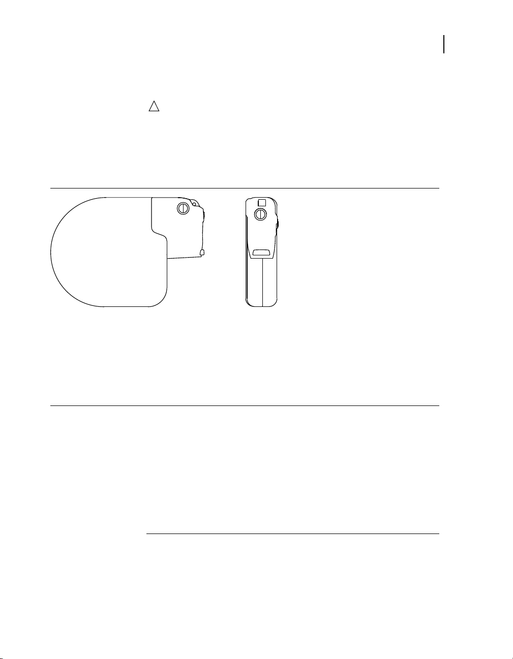
3.1.3 Mechanical Emergency VVI button on the Medtronic CareLink Model 2090 programmer
If you press the red Emergency VVI button on the programmer
display panel, the device initiates Emergency VVI pacing and the
programmer displays the Emergency screen.
1
If Active Can is turned off, the defibrillation is delivered between the HVX
and HVB electrodes.
INSYNC SENTRY®7299 Reference Manual

38
2
4
3
Chapter 3
Delivering an emergency defibrillation therapy
3.1.4 Temporary parameter values
Emergency tachyarrhythmia therapies use temporary values
that do not change the programmed parameters of the device.
These values are not in effect until you select [DELIVER]. After
the tachyarrhythmia therapy is complete, the device reverts to
its programmed values.
3.2 Delivering an emergency defibrillation therapy
The default emergency therapy is a full-energy defibrillation.
When you select [Emergency] and [DELIVER], the device charges
and delivers a biphasic full-energy shock. The programmer sets
the emergency defibrillation energy to its maximum value each
time you select [Emergency] or select the [Defibrillation] option
from an Emergency screen.
3.2.1 How to deliver emergency defibrillation
1. Position the programming head
over the device.
2. Select [Emergency].
3. Accept the defibrillation energy
shown on the screen, or select
a new Energy value.
4. Select [DELIVER].
If delivery is not confirmed,
verify that the programming
head is properly positioned, and
select [Retry] or [Cancel].
2
2
INSYNC SENTRY®7299 Reference Manual
Delivery of Emergency VVI Pacing changes the programmed bradycardia
pacing values to the emergency values (see Section 3.5).

3Emergency therapy
2
5
4
3
Delivering an emergency cardioversion therapy
3.3 Delivering an emergency cardioversion therapy
When you initiate an emergency cardioversion therapy, the device
charges its capacitors to the selected energy and attempts to
deliver therapy synchronized with a sensed tachyarrhythmia
event. If the cardioversion therapy cannot be synchronized, it is
aborted. See Section 7.3.5.6.
3.3.1 How to deliver emergency cardioversion
1. Position the programming head
over the device.
2. Select [Emergency].
3. Select [Cardioversion].
4. Accept the defibrillation energy
shown on the screen, or select
a new Energy value.
5. Select [DELIVER].
If delivery is not confirmed,
verify that the programming
head is properly positioned and
select [Retry] or [Cancel].
39
3.4 Delivering emergency fixed burst pacing
Emergency fixed burst pacing delivers maximum output pacing
pulses to the ventricle at a selectable interval. The therapy
continues for as long as you keep the programmer stylus on the
[BURST Press and Hold] button.
INSYNC SENTRY®7299 Reference Manual

40
3
4
2
5
Chapter 3
Enabling emergency VVI pacing
3.4.1 How to deliver emergency fixed burst pacing
3.5 Enabling emergency VVI pacing
1. Position the programming head
over the device.
2. Select [Emergency].
3. Select [Fixed Burst].
4. Accept the pacing interval
shown on the screen, or select
a new interval value.
5. Select [BURST Press and Hold].
If delivery is not confirmed,
the programmer displays an
error window. Verify that the
programming head is properly
positioned. Select [OK] from the
window and reselect [BURST
Press and Hold].
Emergency VVI pacing programs the device to deliver high-output
ventricular pacing. You can initiate emergency VVI pacing
from the Emergency screen or by pressing the red mechanical
button on the Medtronic CareLink Model 2090 programmer
display panel. To disable emergency VVI pacing, reprogram the
bradycardia pacing parameters from the Parameters screen.
INSYNC SENTRY®7299 Reference Manual
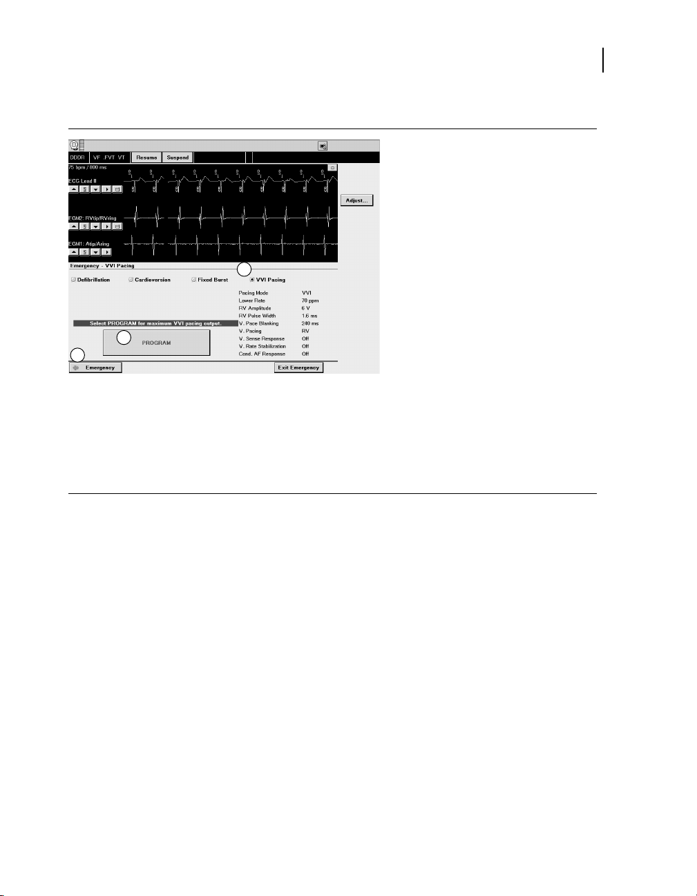
3.5.1 How to deliver emergency VVI pacing
3
4
2
3Emergency therapy
Enabling emergency VVI pacing
1. Position the programming head
over the device.
2. Select [Emergency].
3. Select [VVI Pacing].
4. Select [PROGRAM]. A
successful programming
sets the device to the following
maximum output bradycardia
pacing values:
Pacing Mode: VVI
•
Lower Rate: 70 ppm
•
RV. Amplitude: 6 V
•
RV. Pulse Width: 1.6 ms
•
V. Pace Blanking: 240 ms
•
V. Pacing: RV
•
V. Sense Response: Off
•
Ventricular Rate
•
Stabilization: Off
Cond AF Response: Off
•
If programming is not confirmed,
verify that the programming
head is properly positioned and
select [Retry] or [Cancel].
41
INSYNC SENTRY®7299 Reference Manual


Device implant and patient follow-up
procedures
Part II


4Implanting the device
4.1 Implant overview 47
4.2 Preparing for an implant 47
4.3 Replacing a device 49
4.4 Surgical approach 50
4.5 Sensing and pacing measurements 54
4.6 Connecting the leads to the device 54
4.7 Testing defibrillation operation and effectiveness 58
4.8 Positioning and securing the device 61
4.9 Completing the implant procedure 61
4


4.1 Implant overview
The tasks for implanting a device include:
1. Preparing for an implant
2. Replacing a device
3. Surgical approach
4. Sensing and pacing measurements
5. Connecting the leads to the device
6. Testing defibrillation operation and effectiveness
7. Positioning and securing the device
8. Completing the implant procedure
These tasks are described in the sections that follow.
4.2 Preparing for an implant
Warning: Keep external defibrillation equipment nearby
for immediate use whenever arrhythmias are possible
or intentionally induced during device testing, implant
procedures, or post-implant testing.
4Implanting the device
Implant overview
47
Warning: Do not permit the patient to contact grounded
equipment that could produce hazardous leakage current
during implant. Resulting arrhythmia induction could result
in the patient’s death.
The device is intended for implant in the pectoral region with
Medtronic transvenous defibrillation leads. Implanting the device
outside of the pectoral region, or the use of an epicardial
defibrillation lead instead of an RVcoil (HVB) may adversely
affect the results of the OptiVol fluid measurements. No claims
of safety and efficacy can be made with regard to other acutely
or chronically implanted lead systems that are not manufactured
by Medtronic.
4.2.1 Equipment for an implant
Medtronic CareLink Programmer Model 2090 and Model
•
2067 or 2067L programming head
Model 9998 software application
•
INSYNC SENTRY®7299 Reference Manual

48
Chapter 4
Preparing for an implant
Model 8090 Analyzer lead analysis device or equivalent
•
pacing system analyzer
external defibrillator
•
Model 5358 Defibrillator Implant Support Device and
•
software application (optional)
4.2.2 Sterile supplies
InSync Sentry and lead system components
•
Programming head sleeve or programming head
•
Analyzer cables
•
Lead introducers or delivery systems appropriate for the
•
lead system
Extra stylets of appropriate length and shape
•
4.2.3 How to set up the implant support instrument
When using an implant support instrument such as the Model 5358
Defibrillator Implant Support device, perform these steps:
1. Calibrate any monitoring or recording equipment while recording
the EGM and marker outputs of the support instrument.
2. Verify the high-energy output of the support instrument by delivering
a high-energy defibrillation shock into the test load.
4.2.4 How to set up the programmer and start the application
1. Set up the programmer as described in the instructions provided
with the programmer.
2. Install the InSync Sentry Model 9998 software on the programmer
if it is not already installed.
3. Place the programming head over the device, and start the
application. Select the device model or select [Auto identify].
Note: The programmer automatically interrogates the device when
the application starts.
4.2.5 How to preprogram the device
Before opening the sterile package, prepare the device for implant as
follows:
INSYNC SENTRY®7299 Reference Manual

4Implanting the device
Replacing a device
1. Check the “Use by” date printed on the package. Do not implant
the device after the “Use by” date because the battery’s longevity
can be reduced.
2. Interrogate the device and print a full summary report.
Note: If the programmer reports that an electrical reset occurred,
do not implant the device. Contact a Medtronic representative.
3. Confirm that the battery voltage is at least 3.0 V at room
temperature.
If the device temperature is lower than room temperature or the
device has delivered a recent high-voltage charge, the battery
voltage will be temporarily lower.
4. Set up data collection parameters and the device internal clock
(see Section 12.9.3, “How to set up data collection”, page 318).
5. Perform a manual capacitor formation (see “Manual capacitor
formation”, page 340).
6. Program the therapy and pacing parameters to values appropriate
for the patient (see Section 8.1.4, “How to program CRT and
bradycardia pacing parameters”, page 158). Ensure that all
tachyarrhythmia detection is programmed to Off (see Chapter 6,
“Detecting tachyarrhythmias”, page 73).
Note: Do not enable VF Detection until the device has been
successfully implanted.
1
49
4.3 Replacing a device
If you are replacing a previously implanted device, turn off device
detection and therapies before explanting.
When implanting the device with a chronic lead system, perform
the following evaluations to ensure appropriate detection and
therapy:
Check the integrity of the chronic high-voltage leads with a
•
test shock, chest x-ray, and inspection.
Perform chronic pacing and sensing measurements.
•
Measure high-voltage lead impedances.
•
Test defibrillation efficacy.
•
Confirm adequate sensing during VF.
•
1
Use the Quick Look screen to verify the voltage; see Section 11.2.2, “Quick
Look observations”, page 264.
INSYNC SENTRY®7299 Reference Manual

50
Chapter 4
Surgical approach
Ensure proper fit of the lead connectors in the device
•
connector block.
Notes:
To meet the implant requirements, it may be necessary to
•
reposition or replace the chronic leads or to add a third
high-voltage electrode.
Any unused leads that remain implanted must be capped.
•
4.3.1 How to explant and replace a device
1. Program all tachyarrhythmia detection to Off.
2. Dissect the leads and the device free from the surrounding tissues
in the surgical pocket. Be careful not to nick or breach the lead
insulation during the process of exposing the system.
3. Loosen each setscrew, and gently retract the lead from the
connector block.
4. Remove the device from the surgical pocket.
5. If the connector pin of any implanted lead shows signs of pitting
or corrosion, replace the implanted lead with a new lead. The
damaged lead should be discarded and replaced to assure the
integrity of the device system.
6. Measure sensing, pacing, and defibrillation efficacy using the
replacement device or an implant support instrument.
4.4 Surgical approach
The InSync Sentry system typically requires that a left ventricular
lead be implanted in the coronary sinus and positioned in a
cardiac vein. For this reason, physicians should expect that
implanting an InSync Sentry system will require more time than
implanting a traditional ICD or pacemaker system.
4.4.1 Implanting the device
In most cases the device is implanted in the pectoral region,
either submuscularly or subcutaneously, using transvenous leads
for pacing, sensing, and high-voltage therapies.
INSYNC SENTRY®7299 Reference Manual

Follow these single-incision guidelines when implanting the
device in the pectoral region. The pocket should be about 1.5
times the size of the device.
Submuscular approach: A single incision that extends over
•
the delta-pectoral groove can provide access to the cephalic
and subclavian veins and access to form the implant pocket.
Place the device sufficiently medial to the humeral head to
avoid interference with shoulder motion.
Subcutaneous approach: The subcutaneous approach can
•
be similar to the approach used in a pacemaker implant. Use
a single transverse incision long enough to permit isolation
of the cephalic and subclavian veins. Place the device quite
far medially to keep the leads away from the axilla, and keep
the upper edge of the device inferior to the incision.
4.4.2 Lead configurations
The device is typically implanted with the following leads:
one transvenous lead for the left ventricle (LV) for pacing
•
one bipolar transvenous lead in the right ventricle (RV) for
•
sensing, pacing, and cardioversion/defibrillation therapies
one bipolar transvenous lead in the atrium (A) for sensing
•
and pacing
4Implanting the device
Surgical approach
51
The InSync Sentry system is an Active Can system in which
the device case serves as a high-voltage electrode. The device
case, the RV coil, and the SVC coil form a 3 electrode system for
simultaneous mode defibrillation and cardioversion. High-voltage
therapies are delivered between the RV coil and the combined
device case and SVC coil.
The device may be implanted with other transvenous leads. Refer
to Section 4.4.4, “Using other transvenous leads”, page 53, for
more information.
Notes:
Medtronic 3.2 mm low-profile leads are not directly
•
compatible with the device IS-1 connector block.
For questions about lead and device compatibility, please
•
contact your Medtronic representative.
INSYNC SENTRY®7299 Reference Manual

52
Chapter 4
Surgical approach
4.4.3 Implanting the lead
Note: Do not implant the LV, atrial, and RV leads in the same
venous access site. Medtronic recommends implanting the LV
lead in the subclavian vein, and the atrial and RV leads in the
cephalic vein.
If inserting the lead using a subclavian approach, position the lead
laterally to avoid pinching the lead body between the clavicle and
the first rib. Pinching the lead may eventually cause conductor
fracture, damage to the insulation, or other damage to the lead.
This may result in complications such as loss of detection, loss of
pacing therapies, or loss of cardioversion/defibrillation therapy.
Certain anatomical abnormalities, such as thoracic outlet
syndrome, may also cause pinching and subsequent fracture
of the lead. If significant resistance is encountered during a
subclavian stick implant procedure, do not force passage of the
lead by adjusting the patient’s posture (by raising the arm or
putting a towel behind the person’s back, for example). Use an
alternate venous entry site instead.
4.4.3.1 Implanting the ventricular leads
Warning: Backup pacing should be readily available during
implant. Use of the delivery system or leads may cause
heart block.
Note: Due to the variability of cardiac venous systems, the
venous anatomy should be assessed before implanting the LV
lead to determine an optimal LV lead position. Before placing a
lead in the coronary sinus, obtain a venogram.
When implanting a LV or RV lead, follow the directions for use in
the respective lead technical manuals.
Final lead positioning should attempt to optimize both cardiac
resynchronization and defibrillation threshold.
When pacing at 10 V using an external pacing device, test
for extracardiac stimulation from the LV lead. If extracardiac
stimulation is present, consider repositioning the lead.
4.4.3.2 Implanting the right atrial lead
Implant the atrial lead in the cephalic vein, if possible. Follow the
directions for use in the lead technical manual.
INSYNC SENTRY®7299 Reference Manual

4.4.3.3 Lead positioning
For the initial lead configuration the following positions are
recommended:
LV tip electrode – Position the LV tip electrode as far laterally into
the coronary venous system as possible (so that deflection of the
LV EGM signal occurs as late as possible in the QRS complex).
RV tip electrode – Position the RV tip electrode as far apically
as possible (so that deflection of the RV EGM signal on the
RV electrode starts early in the QRS complex). Defibrillation
threshold, atrial far-field sensing and RV-LV timing must be
considered when choosing the optimal location.
Atrial tip electrode – The atrial tip electrode should be positioned
close to the SA node or on the lateral wall to minimize the
possibility of far-field R-wave oversensing. Lead placement in
these positions potentially provides optimal atrial sensing while
reducing far-field R-wave sensing.
4.4.4 Using other transvenous leads
4Implanting the device
Surgical approach
53
Follow the general guidelines below for initial positioning of
other transvenous leads (the final positions are determined by
defibrillation efficacy tests):
For an SVC lead, place the lead tip high in the innominate
•
vein, approximately 5 cm proximal to the atrium (A) and
SVC junction.
For an SQ patch lead, place the patch along the left
•
midaxillary line, centered over the fourth-to-fifth intercostal
space.
4.4.5 Using epicardial lead systems
Note: The OptiVol Fluid Monitoring feature may be adversely
affected by the use of an epicardial defibrillation lead instead of
an RVcoil.
Observe the following guidelines when epicardial lead systems
are implanted:
The distance between the RVring electrode and the RVtip
•
electrode should not exceed 1 cm.
The RVtip electrode should not lie in a direct path between
•
epicardial patches.
INSYNC SENTRY®7299 Reference Manual

54
Chapter 4
Sensing and pacing measurements
The RVtip/RVring and Atip/Aring intrinsic, post-pace, and
•
post shock electrograms should be thoroughly evaluated for
oversensing, undersensing, cross-talk, and noise.
The pacing thresholds and electrogram characteristics
•
should meet the values indicated in Table 9.
4.5 Sensing and pacing measurements
Sensing and pacing measurements include EGM amplitudes,
slew rates, capture thresholds, and pacing lead impedances.
Medtronic recommends using the Model 8090 Analyzer for
sensing and pacing measurements. Refer to the Analyzer
technical manual for detailed procedures on performing these
measurements.
Do not use the intracardiac EGM telemetered from the device
to assess sensing.
Table 9 lists the acceptable implant values for acute and
chronically implanted lead systems.
Table 9. Acceptable implant values
Measurement required Acute Chronic
A RV LV A RV LV
EGM amplitude (during NSR) ≥ 2 mV ≥ 5 mV ≥ 3 mV ≥ 1 mV ≥ 3 mV ≥ 1 mV
Slew rate
Capture threshold (0.5 ms
pulse width)
Typical pacing lead
impedance
a
Verify adequate pacing threshold margins at implant and at each follow-up visit.
b
The measured pacing lead impedance is a reflection of measuring equipment and lead technology.
c
Refer to the technical manual for the specific lead model for detailed information about acceptable
impedance values.
a
b
≥
0.5 V/s≥0.75 V/s
≤ 1.5 V ≤ 1.0 V ≤ 3.0 V ≤ 3.0 V ≤ 3.0 V ≤ 4.0 V
250 - 1000 Ùc(all)
—
≥
0.3 V/s≥0.5 V/s
—
4.6 Connecting the leads to the device
For more detailed information about lead/connector compatibility,
see the
Medtronic representative.
INSYNC SENTRY®7299 Reference Manual
InSync Sentry 7299 Implant Manual, or contact your

4Implanting the device
2
5
4
6
3
1
Connecting the leads to the device
Table 10. Lead connections
Device port Connector type Software name
SVC (HVX) DF-1 SVC
RV (HVB) DF-1 RVcoil
Can (HVA)
RV IS-1 bipolar RVtip and RVring
LV IS-1 bipolar LVtip and LVring
A IS-1 bipolar Atip and Aring
Figure 3. Device ports for lead connections
—
Can
55
1 SVC (HVX)
2 RV (HVB)
3 Can (HVA)
4 LV
5 RV
6 A
Caution: Loose lead connections may result in inappropriate
sensing and failure to deliver necessary arrhythmia therapy.
Cautions:
To ensure appropriate sensing and detection, insert the
•
right ventricular lead IS-1 connector into the RV port and
insert the right ventricular lead DF-1 connector into the
RV (HVB) port.
If no SVC electrode is implanted, the pin plug provided
•
with the device must be secured in the SVC (HVX) port.
Use only the torque wrench supplied with the device.
•
It is designed to prevent damage to the device from
overtightening a setscrew.
INSYNC SENTRY®7299 Reference Manual

56
Chapter 4
Connecting the leads to the device
Notes:
•
•
•
Do not reuse the torque wrench after this implant.
•
Lead and Active Can electrodes in electrical contact
•
with each other during a high-voltage therapy could
cause current to bypass the heart, possibly damaging
the device and leads. While the device is connected to
the leads, make sure that no therapeutic electrodes,
stylets, or guide wires are touching or connected by an
accessory low impedance conductive pathway. Move
any objects that contain conductive materials (e.g., an
implanted guide wire) well away from all electrodes before
a high-voltage shock is delivered.
For easier lead insertion, insert the LV IS-1 lead before the
other leads.
If a chronic lead system uses a different size or number of
leads, insert the lead connectors into appropriate adaptors.
See the appropriate lead technical manuals for more details.
Upon initial lead connection to the connector block, LVtip,
RVtip, and RVcoil all need to be connected within the
connector block to provide biventricular pacing.
INSYNC SENTRY®7299 Reference Manual

4Implanting the device
a
b
1
2
57
Connecting the leads to the device
4.6.1 How to connect the lead to the device
1. Insert the torque wrench into
the appropriate setscrew.
a. If the port is obstructed by
the setscrew, retract the
setscrew to clear it. Take
care not to disengage the
setscrew from the connector
block.
b. Leave the torque wrench in
the setscrew until the lead
is secure. This allows a
pathway for venting trapped
air when the lead is inserted.
2. Push the lead or plug into the
connector port until the lead
pin is clearly visible in the pin
viewing area. No sealant is
required, but sterile water may
be used as a lubricant.
3. Tighten the setscrew by turning
clockwise until the torque
wrench clicks.
4. Tug gently on the lead to confirm
a secure fit. Do not tug on the
lead until all setscrews have
been tightened.
5. Repeat these steps for each
connector port.
4.6.2 Post pace oversensing testing
Changes in the programmed ventricular pacing configuration (RV,
RV→LV, or LV→RV) may evoke slightly different EGMs. To ensure
proper sensing regardless of the pacing configuration, or in the
event of lead dislodgment or failure, the sensing behavior during
pacing for all configurations should be evaluated as follows:
1. Program RV Pacing.
2. Print a 10 to 30 s test strip.
3. Check for post pace oversensing.
INSYNC SENTRY®7299 Reference Manual

58
Chapter 4
Testing defibrillation operation and effectiveness
Repeat Step 1 through Step 3 with ventricular pacing programmed
to RV→LV and LV→RV.
If oversensing occurs during one of the pacing configurations,
repositioning of the RV lead may help alleviate the oversensing.
4.7 Testing defibrillation operation and effectiveness
Demonstrate reliable defibrillation effectiveness with the implanted
lead system by using your preferred method to establish that a
10 J (minimum) safety margin exists.
Note: If the 10 J (minimum) safety margin cannot be ensured,
see Section 15.5, “Solving tachyarrhythmia therapy problems”,
page 365.
4.7.1 High-voltage implant values
Measured values must meet the following requirements at implant.
Table 11. High-voltage therapy values at implant
Measurement Acute or Chronic Leads
V. Defib impedance 20 – 200 Ù
SVC (HVX) impedance (if applicable) 20 – 200 Ù
Defibrillation threshold ≤ 25 J
Warning: Ensure that an external defibrillator is charged for
a rescue shock.
4.7.2 How to prepare for defibrillation threshold testing
1. Place the programming head over the device, start a patient
session, and interrogate the device, if you have not already done so.
2. Observe the Marker Channel telemetry annotations and the
programmer ECG display to verify that the device is sensing
properly.
INSYNC SENTRY®7299 Reference Manual

4Implanting the device
Testing defibrillation operation and effectiveness
2
3. Conduct a manual Lead Impedance Test
lead connections. Perform this test with the device in the surgical
pocket, and keep the pocket very moist. If the impedance is out of
range, perform one or more of the following tasks:
Recheck lead connections and electrode placement.
•
Repeat the measurement.
•
Inspect the bipolar EGM for abnormalities.
•
Measure the defibrillation impedance with a manual test shock.
•
4. Program the device or support instrument to properly detect VF
with an adequate safety margin (1.2 mV sensitivity).
to verify the defibrillation
59
2
See Section 13.4, “Measuring lead impedance”, page 335 .
INSYNC SENTRY®7299 Reference Manual

60
1
2
3
4
5
6
7 8
9
10
11
12
13
14
Chapter 4
Testing defibrillation operation and effectiveness
4.7.3 How to perform defibrillation threshold testing
1. Select Tests > EP Study.
2. Select either 50 Hz BURST or
T-shock induction.
3. Select [Resume at BURST] or
[Resume at DELIVER].
4. Select [Adjust Permanent…].
5. Program VF Enable On.
6. Program the automatic therapy
energy settings. Therapies 2
through 6 should be set to the
maximum energy.
7. Select [Program].
8. Select [Close].
9. If performing a T-Shock
induction, select the [Enable]
checkbox.
10. Select [DELIVER], or [50 Hz
BURST Press and Hold].
If necessary, you can abort an
induction or therapy in progress
by pressing [ABORT].
11. Observe the live rhythm monitor
for proper post-shock sensing.
12. Use the [Adjust Permanent…]
button to program the next
appropriate energy level.
13. Wait until the on-screen timer
reaches 5 min, then repeat
Step 9 through Step 12 as
needed.
14. Select Params > Detection
and program VF, FVT, and VT
detection Off before closing.
INSYNC SENTRY®7299 Reference Manual
Positioning and securing the device
4.8 Positioning and securing the device
Cautions:
If no SVC electrode is implanted, the pin plug provided
•
with the device must be secured in the SVC (HVX) port.
Program tachyarrhythmia detection to Off before closing.
•
4.8.1 How to position and secure the device
1. Ensure that each lead pin or
plug is fully inserted into the
connector block and that all
setscrews are tight.
2. Coil any excess lead length
beneath the device. Avoid kinks
in the lead conductors.
3. Implant the device within
5 cm of the skin and with the
Medtronic label facing the
skin for improved Patient Alert
volume. This position optimizes
the ambulatory monitoring
operations.
4. Use nonabsorbable sutures to
secure the device within the
pocket to minimize post-implant
rotation and migration of the
device. Use a surgical needle to
penetrate the suture holes.
4Implanting the device
61
4.9 Completing the implant procedure
After implanting the device, obtain an x-ray of the patient to verify
device and lead placement. To complete programming the device,
select parameters that are appropriate for the patient.
4.9.1 How to complete programming the device
1. After closing the pocket, program detection to On. Program
ventricular tachyarrhythmia therapies to On as desired.
2. Do not enable the Other 1:1 SVTs PR Logic detection criterion until
the atrial lead has matured (approximately 1 month post implant).
INSYNC SENTRY®7299 Reference Manual

62
Chapter 4
Completing the implant procedure
3. If external equipment was used to conduct the defibrillation efficacy
4. Monitor the patient after the implant, and take x-rays as soon as
5. Program patient information. See Section 12.10, “Viewing and
6. Configure the Patient Alert feature. See Section 11.3, “Using the
7. Set up data collection parameters. See Section 12.9, “Setting up
8. Interrogate the device after any spontaneous episodes to evaluate
9. If the patient has not experienced spontaneous episodes, you
10. Recheck pacing and sensing values, and adjust if necessary. See
tests, perform a final VF induction, and allow the implanted system
to detect and treat the arrhythmia.
possible to document and assess the location of the leads.
entering patient information”, page 322.
Patient Alert feature”, page 265.
data collection”, page 316.
the detection and therapy parameter settings.
may induce the clinical tachyarrhythmias using the non-invasive
EP Study features to further assess the performance of the
system. See Chapter 14, “Conducting Electrophysiologic Studies”,
page 341.
Section 13.3, “Measuring pacing thresholds”, page 332.
INSYNC SENTRY®7299 Reference Manual

5Conducting a patient follow-up session
5.1 Patient follow-up guidelines 65
5.2 Verifying the status of the implanted system 65
5.3 Verifying effective cardiac resynchronization therapy 66
5.4 Verifying effective basic pacing 67
5.5 Verifying accurate detection and appropriate therapy for ventricular tachyarrhythmias 68
5


5Conducting a patient follow-up session
5.1 Patient follow-up guidelines
Schedule regular patient follow-up sessions to monitor the
condition of the device and leads and to verify that the device is
configured appropriately for your patient.
During the first few months after receiving a new device, the
patient may require close monitoring. Schedule an office visit
at least every 3 months.
The Quick Look screen, which is displayed after you interrogate
the device, provides a good beginning for the follow-up review.
Using this screen you can perform the following tasks:
Verify that the device is functioning correctly.
•
Verify that the device is delivering biventricular pacing most
•
or all of the time.
Review the clinical performance and long term trends.
•
Print appropriate reports to compare the results to the
•
patient’s history and to retain for future reference.
For details about reviewing clinical trend data, see
Section 12.4, “Viewing the Heart Failure Management
•
report”, page 289
65
Patient follow-up guidelines
Section 12.5, “Viewing clinical trends in the Cardiac
•
Compass report”, page 293
Note: The Checklist feature displays a list of standard follow-up
tasks on the programmer screen for easy reference during the
follow-up session. You can also customize your own checklists if
you wish. See Section 11.4, for more information.
5.2 Verifying the status of the implanted system
To verify that the device and leads are functioning correctly,
review the following information from the Quick Look screen and
perform follow-up tests as indicated:
Review the displayed battery voltage for comparison to the
•
Elective Replacement Indicator value (see Section 1.4,
“Replacement indicators”, page 21). Remember that battery
INSYNC SENTRY®7299 Reference Manual

66
Chapter 5
Verifying effective cardiac resynchronization therapy
voltage may be low if high-voltage charging has occurred
within 24 hours.
Review the last full-energy charge.
•
– For information about adjusting the capacitor formation
interval, see Section 9.1, “Optimizing charge time”,
page 217.
– If the programmer displays an Excessive Charge Time
ERI, the device should be replaced immediately.
Review the defibrillation and pacing lead impedance values
•
for inappropriate values or large changes since the last
follow-up session. See Section 13.4, “Measuring lead
impedance”, page 335.
Perform an EGM Amplitude test in the RV and atrium for
•
comparison to previous EGM amplitude measurements.
See Section 13.5.5, “How to perform an EGM Amplitude
test”, page 339.
To review longer term trends in sensing and impedance
•
measurements, select the [>>] button from the lead
performance area of the Quick Look screen. The
programmer displays a detailed history of automatic sensing
and impedance measurements. See Section 11.2, “Taking a
quick look at device activity”, page 264.
5.3 Verifying effective cardiac resynchronization therapy
To verify that the device is providing cardiac resynchronization
therapy appropriately, review the following information from the
initial interrogation report or Quick Look screen and investigate as
indicated:
Confirm that the patient is receiving adequate cardiac
•
support for daily living activities.
Review Quick Look Observations related to ventricular
•
pacing percentage or ventricular sensing episodes.
Check the stored Ventricular Sensing Episode records for
•
appropriate interventions and continuity of resynchronization
pacing. See Section 12.7, “Viewing episode data”, page 305.
Check the rate histograms for more information on atrial and
•
ventricular pacing in general, and ventricular rates during
AT/AF episodes.
INSYNC SENTRY®7299 Reference Manual

•
5.3.1 Considerations
Review the following information before assessing
resynchronization therapy.
•
•
5Conducting a patient follow-up session
Verifying effective basic pacing
Review the Heart Failure Management and Cardiac
Compass reports for comparison to patient history (see
Section 12.4, “Viewing the Heart Failure Management
report”, page 289, and Section 12.5, “Viewing clinical trends
in the Cardiac Compass report”, page 293).
Undersensing, far-field oversensing, or loss of capture
are basic pacing issues that can affect delivery of cardiac
resynchronization therapy. These situations can often
be resolved with basic programming changes and then
monitored for further occurrences.
If CRT delivery is lost during AF or during atrial rate
excursions, consider the following programming options:
– Perform basic programming changes to increase the
Upper Tracking Rate or decrease the total atrial refractory
period (for information on total atrial refractory period,
see Section 8.2.4, “Programming considerations for atrial
rates”, page 169).
– Enable Ventricular Sense Response, Atrial Tracking
Recovery, or Conducted AF Response to promote more
continuous delivery of CRT.
67
5.4 Verifying effective basic pacing
To verify that the device is sensing and pacing appropriately,
review the following information from the Initial Interrogation
Report, and Quick Look screen, and investigate as indicated:
Confirm that the patient is receiving adequate cardiac
•
support for daily living activities.
Review the pacing conduction history and rate histograms
•
for comparison to the patient history. A sharp increase
in the atrial pacing percentage may indicate a need for
investigation and analysis.
Review the recorded Mode Switch episodes for comparison
•
to the patient’s atrial arrhythmia history (see Section 12.7,
“Viewing episode data”, page 305). A dramatic increase in
frequency or duration of atrial episodes may indicate a need
for investigation and analysis.
INSYNC SENTRY®7299 Reference Manual

68
Chapter 5
Verifying accurate detection and appropriate therapy for ventricular tachyarrhythmias
Review the Cardiac Compass report for comparison to
•
patient history (see Section 12.5, “Viewing clinical trends in
the Cardiac Compass report”, page 293).
Conduct pacing threshold tests (see Section 13.3,
•
“Measuring pacing thresholds”, page 332) to verify that
the programmed pacing outputs provide a sufficient safety
margin.
5.4.1 Considerations
Review the following information before verifying bradycardia
pacing.
Atrial pacing – If the conduction history or rate histograms show
a predominance of atrial pacing despite a healthy sinus response,
consider these options to decrease the atrial pacing burden:
Decrease the Lower Rate.
•
Decrease the rate response or increase the activity
•
threshold.
Conduction history – If the reported percentages in the
conduction history do not add up to 100, the percentages may
be rounded.
5.5 Verifying accurate detection and appropriate therapy for ventricular tachyarrhythmias
To verify that the device is providing effective tachyarrhythmia
detection and therapy, review the following information from the
Quick Look screen and investigate as indicated:
Review Quick Look Observations that relate to patient history
•
and device operation. To display more detailed information
about any observation, select the observation and then
select the [>>] button.
Review any Patient Alerts listed in the Observations of the
•
Quick Look screen. For the most detailed information about
Patient Alerts, select Patient Alert from the Data icon and
select [System Events].
Check stored episode records for appropriate sensing
•
and detection of arrhythmias. See Section 12.7, “Viewing
episode data”, page 305.
INSYNC SENTRY®7299 Reference Manual

•
5.5.1 Considerations
Review the following information before verifying detection and
therapy.
Flashback memory – In addition to the episode text and stored
electrograms, use Flashback memory and interval plots to help
investigate the accuracy and specificity of ventricular detection.
Episode misidentification – If the episode records indicate that
false detections have occurred, the Sensing Integrity counter may
help in determining the prevalence of oversensing. For more
information, see Section 12.2.4.3, “Sensing integrity counter”,
page 285.
If the device is oversensing, consider these programming options:
•
•
5Conducting a patient follow-up session
Verifying accurate detection and appropriate therapy for
ventricular tachyarrhythmias
Check stored SVT episode records for appropriate
identification of SVTs.
Increase the Pace Blanking value.
Increase the sensitivity threshold.
Caution: Do not reprogram the device to decrease
oversensing without ensuring that appropriate sensing is
maintained. See Section 6.2, “Setting up sensing”, page 78.
69
If the episode records reveal that a stable monomorphic VT has
been identified and treated as VF, consider these options to
improve the detection accuracy:
Review the Interval Plot for the episode, and adjust the VF
•
Interval, if necessary. Use caution when reprogramming the
VF Interval, because changes to this value can adversely
affect VF detection.
Consider enabling FVT via VF detection. See Section 6.5,
•
“Detecting FVT episodes”, page 92.
If the SVT episode records include episodes of true VT, review
the SVT episode record to identify the SVT detection criterion that
withheld detection. Adjust the SVT detection criteria parameters
as necessary. See Section 6.8, “Enhancing detection with
PR Logic criteria”, page 103, and Section 6.9, “Enhancing VT
detection with the Stability criterion”, page 111.
INSYNC SENTRY®7299 Reference Manual


Configuring the device for the patient
Part III


6Detecting tachyarrhythmias
6.1 Detection overview 75
6.2 Setting up sensing 78
6.3 Detecting VF episodes 83
6.4 Detecting VT episodes 86
6.5 Detecting FVT episodes 92
6.6 Detecting tachyarrhythmia episodes with Combined Count 97
6.7 Monitoring episodes for termination or redetection 99
6.8 Enhancing detection with PR Logic criteria 103
6.9 Enhancing VT detection with the Stability criterion 111
6.10 Detecting double tachycardias 113
6.11 Detecting prolonged tachyarrhythmias with High Rate Timeout 114
6


6.1 Detection overview
The device detects ventricular tachyarrhythmias (VF, VT, and
FVT) by comparing the time intervals between sensed ventricular
events to a set of programmable detection intervals. If enough
intervals occur that are shorter than the programmed intervals,
the device detects a tachyarrhythmia and responds automatically
with a programmed therapy. After delivering the therapy, the
device either redetects the arrhythmia and delivers the next
programmed therapy or detects episode termination.
To avoid detecting rapidly conducted SVTs (for example, sinus
tachycardia or atrial fibrillation) as ventricular tachyarrhythmias,
the device provides several detection enhancements, including
PR Logic and Stability detection criteria.
All of the detection features interact during initial detection (see
Figure 4). During redetection, the device does not apply the PR
Logic detection criteria.
Note: Detection functions can be turned off by programming the
VF Enable, FVT Enable, and VT Enable parameters to Off. For
an example, see Section 6.3.4, “How to program VF detection”,
page 85.
6Detecting tachyarrhythmias
Detection overview
75
INSYNC SENTRY®7299 Reference Manual
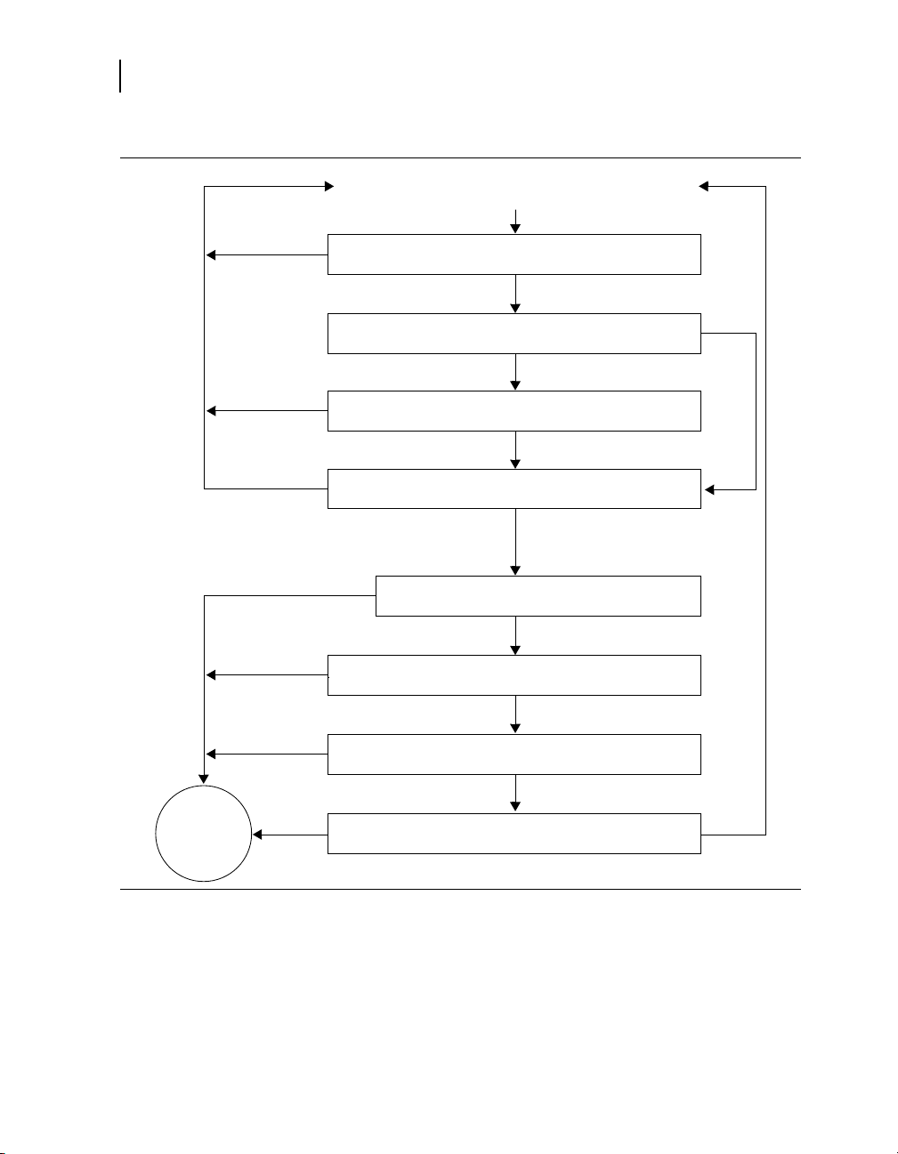
76
Ventricular Event
No
No
No
Yes
Yes
Yes
Yes
Yes
Yes
No
No
No
No
Yes
Yes
Update counts and pattern information
Is the interval in the VF, FVT, or VT detection zone?
Has High Rate Timeout suspended detection enhancements?
Does Stability reset the VT event count? (VT and FVT via VT
detection only)
Has a tachyarrhythmia event count reached an NID?
Are one or more PR Logic criteria on?
No/suspended by High Rate
Timeout
Tachy
Episode
Detected
Is the median ventricular interval less than the SVT Limit?
Is there a double tachycardia in progress?
Are one or more PR Logic criteria withholding detection?
Chapter 6
Detection overview
Figure 4. How detection features interact during initial detection
6.1.1 Suspending tachyarrhythmia detection
INSYNC SENTRY®7299 Reference Manual
When detection is suspended, the device temporarily stops
classifying and counting tachyarrhythmia intervals. Sensing
and programmed pacing remain active, and the programmed
detection settings are not modified.

6Detecting tachyarrhythmias
Detection overview
Detection is suspended:
when the device senses the presence of a strong magnet.
•
The programmer head contains a magnet which suspends
detection, but once telemetry between the device and
programmer is established, detection resumes.
while performing any of the manual system tests, including
•
Underlying Rhythm, Pacing Threshold, Lead Impedance,
EGM Amplitude, and Charge/Dump. Detection automatically
resumes once the test is complete.
while performing a T-Shock, 50 Hz Burst, Manual Burst,
•
or PES Induction. You can choose to have the device
automatically resume detection after delivering the induction.
when you deliver a Manual or Emergency therapy. You
•
can resume detection by selecting the [Resume] button or
removing the programming head from the device.
when you select the on-screen [Suspend] button. You can
•
resume detection by selecting the [Resume] button or by
removing the programming head from the device.
during the automatic daily lead impedance measurements.
•
Detection resumes when the measurements are complete.
while the device is delivering an automatic tachyarrhythmia
•
therapy (including capacitor charging for defibrillation and
cardioversion). However, the device does continue to confirm
the detected episode during charging. Detection resumes
when the therapy is complete.
Note: The device suspends VT detection and Combined
Count detection (see Section 6.6, “Detecting tachyarrhythmia
episodes with Combined Count”, page 97) for 17 events
following a defibrillation therapy delivered in response to a
detected VF.
during charging for Automatic Capacitor Formation.
•
1
Detection resumes when charging is complete.
77
1
If the defibrillation therapy is delivered as a result of either a High Rate
Timeout Therapy operation or Progressive Episode Therapies operation,
VT detection is not suspended (see Section 6.11.4.1, “High Rate Timeout
Therapy”, page 116).
INSYNC SENTRY®7299 Reference Manual

78
Chapter 6
Setting up sensing
6.2 Setting up sensing
The device provides bipolar sensing in both the atrium and right
ventricle using the sensing electrodes of the implanted atrial
and RV leads. You can adjust the sensitivity to intracardiac
signals using independent atrial and ventricular sensitivity
settings. These settings define the minimum electrical amplitude
recognized by the device as an atrial or ventricular sensed event.
Proper sensing is essential for the safe and effective use of the
device. To provide appropriate sensing, the device uses:
auto-adjusting atrial and ventricular sensing thresholds
•
short (30 ms) cross-chamber blanking after paced events
•
no cross-chamber blanking after sensed events
•
See Section 6.2.4, “Details about sensing”, page 80.
6.2.1 Parameters
V. Sensitivity – Minimum amplitude of
electrical signal that registers as a sensed
ventricular event.
A. Sensitivity – Minimum amplitude of
electrical signal that registers as a sensed
atrial event.
6.2.2 Considerations
Review the following information before programming sensing
parameters.
Dual chamber sensing and pacing modes – The device senses
in both the atrium and the right ventricle at all times, except when
the programmed bradycardia pacing mode is DOO. When the
pacing mode is programmed to DOO or VOO mode, there is no
sensing in the ventricle.
mode, you must first disable detection.
Sensitivity thresholds – The programmed atrial and ventricular
sensitivity thresholds apply to all features related to sensing,
including detection and bradycardia pacing.
2
Atrial sensing occurs in VOO mode.
0.15; 0.3
0.9; 1.2 mV
0.15; 0.3
0.9; 1.2; 1.5; 2.1 mV
2
In order to program either DOO or VOO
; 0.45; 0.6;
; 0.45; 0.6;
INSYNC SENTRY®7299 Reference Manual

6Detecting tachyarrhythmias
Setting up sensing
Bradycardia pacing and sensing – A combination of high
pacing pulse width or high amplitude with a low sensitivity
threshold may cause inappropriate sensing across chambers or
in the same chamber. Programming a lower pulse width, lower
amplitude, longer pace blanking, or a higher sensitivity threshold
may eliminate this inappropriate sensing.
Recommended ventricular sensitivity threshold – A
ventricular sensitivity threshold of 0.3 mV is recommended to
maximize the probability of detecting VF and to limit the possibility
of oversensing and cross-chamber sensing.
High ventricular sensitivity threshold – Setting V. Sensitivity
to a value greater than 0.6 mV is not recommended except for
testing. Doing this may cause undersensing, which can cause
any of the following situations:
delayed or aborted cardioversion therapy
•
delayed defibrillation therapy (when VF confirmation is
•
active)
asynchronous pacing
•
underdetection of tachyarrhythmias
•
79
Low ventricular sensitivity threshold – If you set V. Sensitivity
to its most sensitive value of 0.15 mV, the device will be more
susceptible to EMI, cross-chamber sensing, and oversensing.
Recommended atrial sensitivity threshold – An atrial sensitivity
threshold of 0.3 mV is recommended to optimize the effectiveness
of PR Logic detection criteria and atrial pacing operations, while
limiting the possibility of oversensing and cross-chamber sensing.
High atrial sensitivity threshold – If you set the A. Sensitivity
value too high, the device may not provide reliable sensing of
P-waves during SVTs and sinus rhythm.
Low atrial sensitivity threshold – If you set the A. Sensitivity
value to its most sensitive value of 0.15 mV, the device will
be more susceptible to EMI, far-field R-wave sensing, and
oversensing.
Testing sensitivity after reprogramming – If you change the
ventricular sensitivity threshold, evaluate for proper sensing and
detection by inducing VF and allowing the device to automatically
detect and treat the arrhythmia.
INSYNC SENTRY®7299 Reference Manual

80
1
2
3
Chapter 6
Setting up sensing
Atrial pacing and ventricular sensing – If you program the
device to an atrial pacing mode, make sure that it does not sense
atrial pacing pulses as ventricular events.
Sensing during VF – Always verify that the device senses
properly during VF. If the device is not sensing or detecting
properly, program detection and therapies off, and evaluate the
system (making sure to monitor the patient for life-threatening
arrhythmias until you enable detection and therapies again). You
may need to reposition or replace the ventricular sensing lead to
achieve proper sensing.
Atrial lead selection – Atrial leads with minimal tip-to-ring
spacing may reduce far-field R-wave sensing.
Repositioning the atrial lead – You may need to reposition
or replace the atrial sensing lead if reprogramming the atrial
sensitivity threshold does not provide reliable atrial sensing during
SVTs and sinus rhythm.
6.2.3 How to program sensitivity
1. Select Params > Detection.
2. Select the desired A. Sensitivity
and V. Sensitivity parameters.
3. Select [PROGRAM].
6.2.4 Details about sensing
6.2.4.1 Auto-adjusting sensitivity thresholds
The device automatically adjusts the sensitivity thresholds after
certain paced and sensed events to help reduce oversensing
from T-waves, cross-chamber events, and pacing. You can see
INSYNC SENTRY®7299 Reference Manual

6Detecting tachyarrhythmias
A
P
V
S
A
S
V
S
A
S
V
P
Sensitivity Threshold
Rectified and
Filtered A. EGM
Rectified and
Filtered RV EGM
Marker Channel
1 2
3
4
5
Setting up sensing
how sensitivity thresholds are adjusted after different types of
events (see Figure 5).
Figure 5. Auto-adjusting sensitivity thresholds
1 After an atrial sensed event, the atrial sensitivity threshold increases
to 75% of the EGM peak (maximum: 8x the programmed value,
decay constant: 200 ms).
2 After a ventricular sensed event, the ventricular sensitivity threshold
increases to 75% of the EGM peak (maximum: 8x the programmed
value, decay constant: 450 ms).
3 After an atrial paced event, the device does not adjust the atrial
sensitivity threshold. The ventricular sensitivity threshold increases
by 0.45 mV (decay constant: 60 ms).
4 After a ventricular paced event, the atrial sensitivity threshold
increases to 4x the programmed value (maximum: 1.8 mV,
immediate return after 60 ms).
5 After the ventricular pace blanking period is finished, the ventricular
threshold increases to 4.5x the programmed value (maximum:
1.8 mV, decay constant: 450 ms).
3
4
4
81
6.2.4.2 Blanking periods
During a blanking period, the device does not sense
electrical signals. This helps prevent sensing of device
pacing, cardioversion and defibrillation pulses, post-pacing
depolarization, T-waves, and multiple sensing of the same event.
3
The exponential decay continues through a subsequent ventricular pacing
pulse and its blanking period.
4
If the programmed sensitivity value exceeds 0.3 mV (ventricular) or 1.2 mV
(atrial), the threshold is not adjusted.
INSYNC SENTRY®7299 Reference Manual

82
Chapter 6
Setting up sensing
The blanking periods following paced events are longer than
those following sensed events to avoid sensing the atrial and
ventricular depolarizations.
Notes:
To enhance sensing and detection during tachyarrhythmias,
•
the device does not apply cross-chamber blanking (blank
sensing in the opposite chamber) after a sensed event.
Atrial sensing is still active during the Post-Ventricular
•
Atrial Blanking (PVAB) period (see Section 8.2.3.5,
“Post-Ventricular Atrial Refractory Period”, page 167).
The duration of the fixed blanking periods is shown in Table 12.
For information on programmable pace blanking periods, see
Section 8.1, “Providing basic pacing therapy”, page 153.
Table 12. Duration of fixed blanking periods
Cross-chamber blanking after atrial or ventricular
pacing pulse
Atrial blanking after sensed atrial event
Ventricular blanking after sensed ventricular event
Atrial and ventricular blanking after delivered
cardioversion or defibrillation therapy
30 ms
100 ms
120 ms
520 ms
6.2.4.3 Refractory periods
During a refractory period, the device senses normally, but
classifies sensed events as refractory and limits its response to
these events. Pacing refractory periods prevent inappropriately
sensed signals, such as far-field R-waves (ventricular events
sensed in the atrium) or electrical noise, from triggering certain
pacing timing intervals.
Synchronization refractory periods help prevent the device
from delivering cardioversion and defibrillation therapies at
inappropriate times. See Section 7.1.5.5, “Synchronizing
defibrillation without confirming VF”, page 123, and
Section 7.3.5.6, “Synchronizing cardioversion after charging”,
page 143.
Note: Refractory periods do not affect tachyarrhythmia detection.
INSYNC SENTRY®7299 Reference Manual

6.3 Detecting VF episodes
The device detects VF episodes by examining the cardiac rhythm
for short ventricular intervals. If a predetermined number of
intervals occur that are short enough to be considered VF
events, the device detects VF and delivers the first programmed
VF therapy. After therapy, the device continues to evaluate the
ventricular rhythm to determine if the episode is ongoing.
See Section 6.3.5, “Details about VF detection”, page 85.
6.3.1 Parameters
VF Detection Enable – Turns VF
detection on or off.
VF Interval (Rate) – V-V intervals
shorter than this value are counted as
VF events.
VF Initial NID – Number of Intervals to
Detect: number of VF events the device
must count to detect a VF episode.
VF Redetect NID – Number of Intervals
to Redetect: number of VF events
the device must count to redetect a
continuing VF after a therapy.
6Detecting tachyarrhythmias
Detecting VF episodes
; Off
On
240; 250 … 320
400 ms
12/16; 18/24
30/40; 45/60; 60/80;
75/100; 90/120; 105/140;
120/160
6/8; 9/12; 12/16
21/28; 24/32; 27/36; 30/40
…
; 24/32;
; 18/24;
83
6.3.2 Considerations
Review the following information before programming VF
Detection parameters.
VF Interval minimum setting – To ensure proper VF detection,
you should not program the VF Interval to a value less than
300 ms.
VF Interval maximum setting – Programming the VF Interval to
a value greater than 350 ms may cause inappropriate detection of
rapidly conducted atrial fibrillation as VF or FVT via VF. Intervals
shorter than the VF Interval are counted using the VF event
counter, which is more sensitive than the consecutive VT event
counter.
INSYNC SENTRY®7299 Reference Manual

84
Chapter 6
Detecting VF episodes
VF, FVT, and VT Intervals – To allow for normal variations in the
patient’s tachycardia interval, you should program the VF, FVT,
and VT intervals at least 40 ms apart.
Episode redetection – You can expedite redetection by
programming the VF and VT Redetect NIDs lower than the Initial
NIDs.
Enabling VF detection – When VF Detection Enable is
programmed On for the first time, the device:
enables Automatic Capacitor Formation
•
starts recording Cardiac Compass data and Heart Failure
•
Management data
starts recording lead performance trends (starting at
•
3:00 AM by the device clock)
clears all brady pacing counters
•
VF detection and PR Logic criteria – You can program the
device to exclude rapidly conducted SVTs from VF Detection by
enabling the PR Logic detection criteria. Note that the SVT Limit
must be programmed shorter than the VF Interval in order for
the PR Logic criteria to affect VF detection. See Section 6.8,
“Enhancing detection with PR Logic criteria”, page 103.
Double tachycardia detection – When any PR Logic detection
criteria are enabled, the device also enables double tachycardia
detection (VF, VT, or FVT in the presence of an SVT). See
Section 6.10, “Detecting double tachycardias”, page 113.
6.3.3 Restrictions
Review the following information before programming VF
Detection parameters.
Tachyarrhythmia detection and pacing – To ensure reliable
ventricular tachyarrhythmia detection, the programmer regulates
the values available for pacing and tachyarrhythmia detection.
See Section B.11, “Parameter interlocks”, page 402.
VF detection backup – To ensure VF Detection backup during
VT and FVT episodes, if VF Detection is off, both VT Detection
and FVT Detection must also be off.
INSYNC SENTRY®7299 Reference Manual

6.3.4 How to program VF detection
1
2
3
6.3.5 Details about VF detection
The device detects VF by counting the number of VF events,
which are V-V intervals shorter than the programmed VF Interval.
On each event, the device counts the number of recent VF
events. The number of recent events that are examined is called
the VF detection window. The size of the VF detection window is
the second number in the programmed VF NID (for example, 24
events if the VF Initial NID is 18/24).
6Detecting tachyarrhythmias
Detecting VF episodes
1. Select Params > Detection.
2. Select the desired values for
VF Enable, VF Initial NID, VF
Redetect NID, and VF Interval.
3. Select [PROGRAM].
85
The threshold for detecting VF is the first number in the
programmed VF NID (for example, 18 events if the VF Initial
NID is 18/24). This threshold is always 75% of the VF detection
window. That is, if 75% of the events in the VF detection window
are VF events, the device detects a VF episode (see Figure 6).
After the device detects VF, it delivers the first programmed
VF therapy. Following the therapy, if the number of VF events
reaches the programmed VF Redetect NID, the device redetects
VF and delivers the next programmed VF therapy.
Note: The device can also detect VF Episodes using the
Combined Count detection criterion (see Section 6.6).
INSYNC SENTRY®7299 Reference Manual

86
A
S
A
S
V SV SV
S
V
S
V SV
S
V
S
A
R
A
R
A
R
A
R
A
R
1 2 3 4 5 6 6 7 8 9 10 11 12 13 14 15 1617 18
F SF SF SF SF SF SF SF SF SF
S
F SF SF
S
F SF SF
S
F
S
F
D
200 ms
2 31
VF Event Count
ECG
Marker Channel
VF Interval
Chapter 6
Detecting VT episodes
Figure 6. Device detects VF
1 VF starts, and the device begins counting VF events (intervals less
than the programmed VF Interval).
2 A ventricular interval occurs outside the VF detection zone. The VF
event count is not incremented.
3 The VF event count reaches the programmed VF NID value of 18
events out of 24, and the device detects VF.
6.4 Detecting VT episodes
The device detects VT episodes by examining the cardiac rhythm
for short ventricular intervals. If enough intervals occur that are
short enough to be considered VT events (but are not VF or FVT
events), the device detects VT and delivers the first programmed
VT therapy. After therapy, the device continues to evaluate the
ventricular rhythm to determine if the episode is ongoing.
You can program the device to detect and record VT episodes
without treating them with VT therapies by setting VT Detection
Enable to Monitor. If a patient’s VT episodes are well-tolerated,
this feature allows you to collect data about these episodes
without delivering therapy or affecting VF detection.
INSYNC SENTRY®7299 Reference Manual
See Section 6.4.5, “Details about VT detection”, page 88.

6.4.1 Parameters
6Detecting tachyarrhythmias
Detecting VT episodes
87
VT Detection Enable – Turns VT
detection on or off, or enables VT
monitoring.
VT Interval (Rate) – V-V intervals
shorter than this value are counted as
VT events.
VT Initial NID – Number of Intervals
to Detect: number of VT events the
device must count to detect a VT
episode.
VT Redetect NID – Number of
Intervals to Redetect: number of
VT events the device must count
to redetect a continuing VT after a
therapy.
6.4.2 Considerations
Review the following information before programming VT
Detection parameters.
VF, FVT, and VT Intervals – To allow for normal variations in the
patient’s tachycardia interval, you should program the VF, FVT,
and VT intervals at least 40 ms apart.
Episode redetection – You can expedite redetection by
programming the VF and VT Redetect NIDs lower than the Initial
NIDs.
On; Off
280; 290 … 400
12; 16
4; 8; 12
; Monitor
…52; 76; 100
… 52
… 600 ms
VT Detection Enable, AFib/AFlutter, and Sinus Tach – When
you set VT Detection Enable to On or Monitor, the AFib/AFlutter
and Sinus Tach parameters are also automatically set to On.
VT detection and Combined Count detection – When VT
Detection is On, the device applies the Combined Count detection
criterion to help speed detection of rhythms that fluctuate between
detection zones. Combined Count detection is disabled if VT
Detection is set to Off or Monitor. See Section 6.6, “Detecting
tachyarrhythmia episodes with Combined Count”, page 97.
VT detection and rapidly conducted SVTs – You can program
the device to exclude rapidly conducted SVTs from VT detection
by enabling the PR Logic or Stability detection criteria. See
Section 6.9, “Enhancing VT detection with the Stability criterion”,
INSYNC SENTRY®7299 Reference Manual

88
1
2
3
Chapter 6
Detecting VT episodes
page 111, and Section 6.8, “Enhancing detection with PR Logic
criteria”, page 103.
Double tachycardia detection – When any PR Logic detection
criteria are enabled, the device also enables double tachycardia
detection (VF, VT, or FVT in the presence of an SVT; see
Section 6.10).
6.4.3 Restrictions
Review the following information before programming VT
detection parameters.
Tachyarrhythmia detection and pacing – To ensure reliable
ventricular tachyarrhythmia detection, the programmer regulates
the values available for pacing and tachyarrhythmia detection.
See Section B.11, “Parameter interlocks”, page 402.
VF detection backup – To ensure VF detection backup during
VT and FVT episodes, if VF Detection is off, both VT Detection
and FVT Detection must also be off.
6.4.4 How to program VT detection
1. Select Params > Detection.
2. Select the desired values for
VT Enable, VT Initial NID, VT
Redetect NID, and VT Interval.
3. Select [PROGRAM].
6.4.5 Details about VT detection
INSYNC SENTRY®7299 Reference Manual
The device detects VT by counting the number of consecutive VT
events. A VT event is a V-V interval shorter than the programmed
VT Interval but greater than or equal to the VF Interval. If the

6Detecting tachyarrhythmias
Detecting VT episodes
number of consecutive VT events reaches the programmed VT
Initial NID, the device detects VT (see Figure 7).
The VT event count resets to zero whenever an interval occurs
that is greater than or equal to the programmed VT Interval. The
count remains at the current value if an interval is shorter than
the programmed VF Interval.
After the device detects VT, it delivers the first programmed VT
therapy. Following the therapy, if the VT event counter reaches
the VT Redetect NID, the device redetects VT and delivers the
next programmed therapy.
Note: The device can also detect VT Episodes using the
Combined Count detection criterion (see Section 6.6, “Detecting
tachyarrhythmia episodes with Combined Count”, page 97).
89
INSYNC SENTRY®7299 Reference Manual

90
A
S
A
S
V SV
S
V
S
V
S
A RA RA RA RA RA RA
R
1 0 1 2 3 4 5 6
T
S
T ST ST ST ST ST
S
V
S
A RA RA RA RA RA RA RA RA RA RA RA
R
7 8 9 10 11 12 13 14 15 16
200 ms
T ST ST ST ST ST ST ST ST
S
T
D
21
3
VT Event Count
ECG
Marker Channel
VT Interval
VT Event Count
ECG
Marker Channel
VT Interval
Chapter 6
Detecting VT episodes
Figure 7. Device detects VT
1 VT starts, and the device begins counting VT events (intervals less
than the programmed VT Interval but greater than or equal to the
VF Interval).
2 A ventricular interval occurs outside VT detection zone. The VT event
count resets to zero.
3 The VT event count reaches the programmed VT NID of 16 events,
and the device detects VT.
6.4.5.1 VT monitoring
You can program the device to record VT episodes without
delivering VT therapy by setting VT Detection to Monitor. When
VT monitoring is enabled, the device detects VT episodes but
does not deliver VT therapy (see Figure 8). Instead, it records VT
episodes, labeling them as “monitored,” and waits for episode
termination to occur.
When VT Detection is set to Monitor, several detection operations
work differently.
INSYNC SENTRY®7299 Reference Manual
VT event counting – Before the device detects an episode, it
counts VT events normally. However, once the VT Initial NID is

6Detecting tachyarrhythmias
Detecting VT episodes
reached, the device sets the VT event count to zero and suspends
VT event counting for the rest of the episode.
VF and FVT detection – VF and FVT detection operate as if
VT detection is off. Specifically, Combined Count detection
is disabled, and FVT via VT detection is not selectable. If a
monitored VT episode accelerates into the FVT or VF detection
zone, the device applies the VF Initial NID to detect the new
tachyarrhythmia. Once an episode is in progress, VT event
counting doesn’t resume until the episode ends.
Caution: Programming the VF Interval greater than 350 ms
may result in inappropriate detection of rapidly conducted
atrial fibrillation as VF or FVT via VF. Intervals shorter than
the VF Interval are counted using the VF event counter,
which is more sensitive than the consecutive VT event
counter.
PR Logic and Stability criteria – Before the device detects a
tachyarrhythmia episode, the PR Logic and Stability criteria, if
turned on, are applied. If a monitored VT episode accelerates
into the FVT or VF detection zone, the device continues to apply
PR Logic criteria as initial VF or FVT detection begins. However,
because the Stability feature does not affect VF detection or FVT
via VF detection, it is not applied.
91
Episode termination – The device compares ventricular intervals
to the VT Interval to identify when a VT monitored episode has
ended. However, if a VF episode or FVT via VF episode occurs
when VT monitoring is enabled, the device compares ventricular
intervals to the VF Interval to identify episode termination.
INSYNC SENTRY®7299 Reference Manual
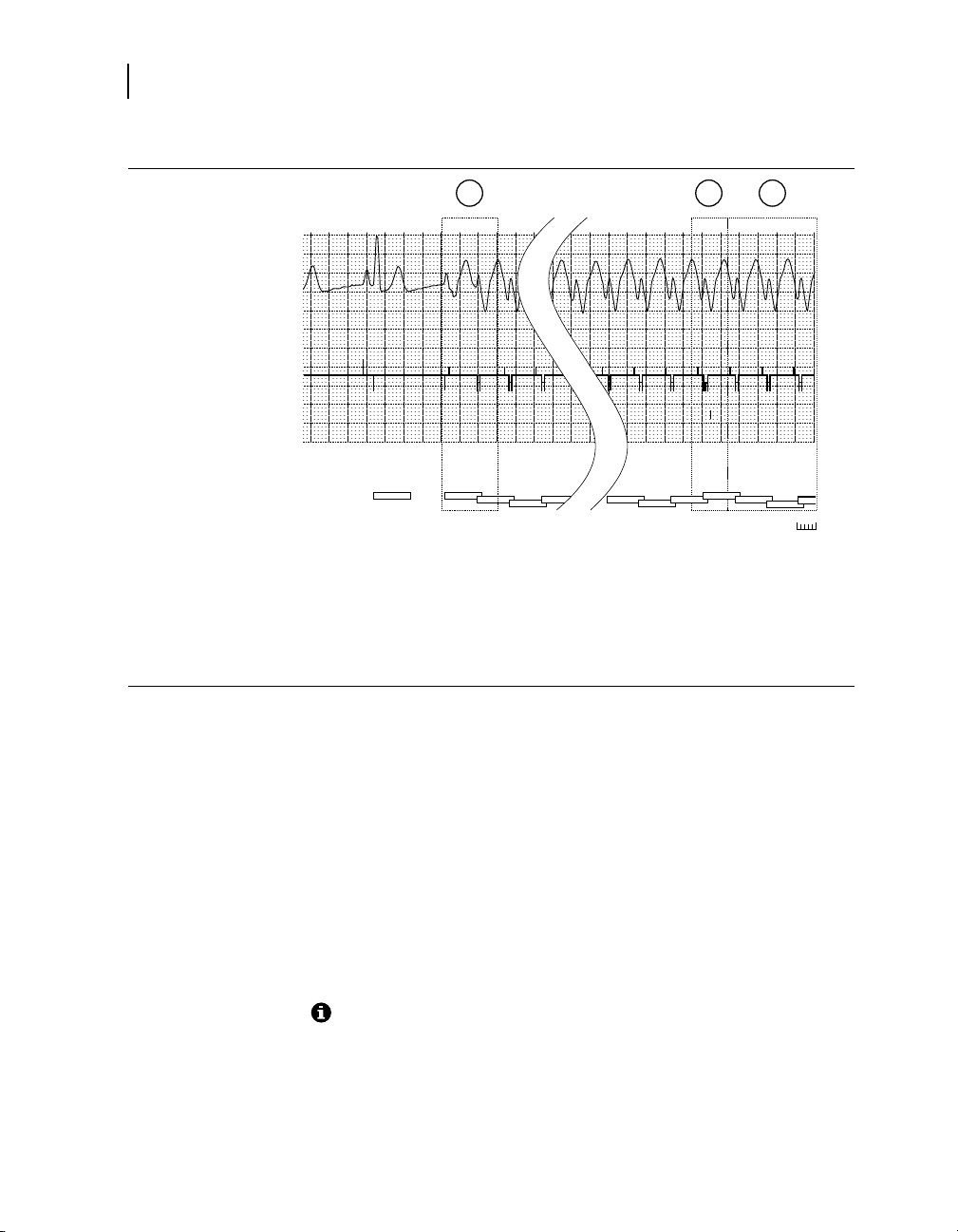
92
200 ms
1 2 3 4
A
S
A
R
A RA RA
R
V
S
V ST ST ST ST
S
13 14 15 16 0 0 0
A
R
A
R
A RA RA RA RA
R
T ST ST ST DT ST ST
S
2 31
VT Event Count
ECG
Marker Channel
VT Interval
Chapter 6
Detecting FVT episodes
Figure 8. Device detects and monitors VT
1 VT starts, and the device begins counting VT events (intervals less
than the programmed VT Interval but greater than or equal to the
VF Interval).
2 The VT event count reaches the programmed VT NID of 16 events,
and the device detects VT.
3 After detecting the VT episode, the device resets the VT event count
to zero and monitors the episode until termination.
6.5 Detecting FVT episodes
The device detects episodes of Fast Ventricular Tachycardia
(FVT) by examining the cardiac rhythm for short ventricular
intervals. If enough intervals occur in the programmed FVT
detection zone, the device detects FVT and delivers the first
programmed FVT therapy. After therapy, the device continues
to evaluate the ventricular rhythm to determine if the episode
is ongoing. To make sure it delivers sufficiently aggressive
therapies, the device can merge the programmed detection zones
during redetection to increase sensitivity.
INSYNC SENTRY®7299 Reference Manual
See Section 6.5.5, “Details about FVT detection”, page 95.

6.5.1 Parameters
FVT Detection Enable – Enables FVT
detection via the VF or the VT detection
algorithm.
FVT Interval (Rate) – V-V intervals between
this value and the programmed VF Interval are
marked as FVT events.
6.5.2 Considerations
Review the following information before programming FVT
Detection parameters.
VF, FVT, and VT Intervals – To allow for normal variations in the
patient’s tachycardia interval, you should program the VF, FVT,
and VT intervals at least 40 ms apart.
Episode redetection – You can expedite redetection by
programming the VF and VT Redetect NIDs lower than the Initial
NIDs.
6Detecting tachyarrhythmias
Detecting FVT episodes
; via VF; via VT
Off
200; 210 … 600 ms
93
FVT detection enable – Your choice for an appropriate setting
for FVT Detection should depend on the patient’s VF and VT
cycle lengths. After determining a reliably sensitive VF Interval,
consider the following suggestions:
If the patient presents with a clinical VT interval in the VF
•
zone, select via VF to ensure reliable detection of VF. (VT
Detection need not be enabled at all.)
If the patient presents with 2 clinical VTs, both outside the
•
VF zone, select via VT to allow for correct classification of
the faster VT and to offer a separate therapy regimen for
each VT.
If the patient presents with only 1 clinical VT, which is outside
•
the VF zone, select VF and VT Detection only, and set FVT
Enable to Off.
FVT detection and PR Logic criteria – You can program the
device to exclude rapidly conducted SVTs from FVT Detection
by enabling the PR Logic detection criteria. Note that the SVT
Limit must be programmed shorter than the VF Interval for the PR
Logic criteria to affect FVT via VF detection.
INSYNC SENTRY®7299 Reference Manual

94
Chapter 6
Detecting FVT episodes
6.5.3 Restrictions
Double tachycardia detection – When any PR Logic detection
criterion is enabled, the device also enables double tachycardia
detection (VF, VT, or FVT in the presence of an SVT, see
Section 6.10).
Review the following information before programming FVT
Detection parameters.
Tachyarrhythmia detection and bradycardia pacing – To
ensure reliable ventricular tachyarrhythmia detection, the
programmer regulates the values available for bradycardia pacing
and tachyarrhythmia detection. See Section B.11, “Parameter
interlocks”, page 402.
VF detection backup – To ensure VF Detection backup during
VT and FVT episodes, VT and FVT Detection cannot be on
unless VF Detection is also on.
FVT detection – To ensure reliable ventricular tachyarrhythmia
detection, the programmer regulates the values available for the
FVT parameter as follows:
VT Detection must be set to On if FVT Detection is set to
•
via VT.
If FVT Detection is set to via VF, the FVT Interval must be
•
programmed to a value shorter than the VF Interval.
If FVT Detection is set to via VT, the FVT Interval must be
•
programmed to a value greater than the VF Interval and less
than or equal to the VT Interval.
INSYNC SENTRY®7299 Reference Manual

6.5.4 How to program FVT detection
1
2
3
6.5.5 Details about FVT detection
You can program the device to detect FVT episodes via the VF
or VT detection zone and NID.
6Detecting tachyarrhythmias
Detecting FVT episodes
1. Select Params > Detection.
2. Select the desired values for
FVT Enable and FVT Interval.
3. Select [PROGRAM].
95
When FVT Detection is set to via VF, a V-V interval within the FVT
detection zone is marked as an “FVT via VF” event. When the VF
NID is reached, the device reviews the last 8 intervals:
If any of the last 8 intervals are in the VF zone, it detects
•
the episode as VF.
If all of the last 8 intervals are outside the VF zone, it detects
•
the episode as FVT (see Figure 9).
When FVT Detection is set to via VT, a V-V interval within the
FVT detection zone is marked as an “FVT via VT” event. When
the VT NID is reached, the device reviews the last 8 intervals:
If any of the last 8 intervals are in the VF or FVT zones, it
•
detects the episode as FVT.
If all of the last 8 intervals are outside the FVT and VF zones,
•
it detects the episode as VT.
Note: The device can also detect FVT episodes via the Combined
Count detection criterion (see Section 6.6).
INSYNC SENTRY®7299 Reference Manual

96
200 ms
13 14 15 16 17 18
A RA RA RA RA RA RA RA RA
R
T FT
F
T FT FT FT FT FV
S
1 1 2 3 4 5
A
S
A
S
A RA RA
R
A
R
V
S
V
S
V
S
T
S
T
F
T FT FT FT
F
1 2
3
VF Event Count
ECG
Marker Channel
VF and FVT Intervals
Chapter 6
Detecting FVT episodes
Figure 9. Device detects FVT via VF
1 A fast ventricular tachycardia starts, and the first event falls into the
FVT detection zone.
2 The second event of the FVT episode has an interval that falls into
the VT zone. The VF event count is not incremented.
3 The device detects FVT after the VF event count reaches the VF
Initial NID.
6.5.5.1 Zone merging after detection
To ensure that the device delivers sufficiently aggressive therapies
during an extended or highly variable tachyarrhythmia episode,
the device merges detection zones during redetection in some
instances, as shown in Figure 10. The merged zone configuration
uses the event counting and therapies for the faster arrhythmia
and remains in effect until episode termination.
INSYNC SENTRY®7299 Reference Manual

Figure 10. FVT zone merging
Before detection
After VF detection
After FVT detection
FVT set to “via VF”
VF and FVT zones merge, leaving a
larger VF zone.
All zones remain unchanged.
FVT set to “via VT”
VT and FVT zones merge, leaving a
larger FVT zone.
VT and FVT zones merge, leaving a
larger FVT zone.
Detection Intervals: VF Interval: 320 ms, FVT Interval: 280 ms / 360 ms, VT
Interval: 400 ms
VF
FVT
VT
VF
FVT
VT
VF
FVT
VT
VF
FVT
VT
VF
FVT
VT
VF
FVT
VT
6Detecting tachyarrhythmias
Detecting tachyarrhythmia episodes with Combined Count
97
6.6 Detecting tachyarrhythmia episodes with Combined Count
Because the device counts VF and VT events separately,
rhythms with variable cycle lengths can cause both event counts
to increment during an episode. To prevent these rhythms
from delaying detection, the device automatically enables the
Combined Count detection criterion if both VF and VT detection
are programmed On.
The Combined Count criterion compares the sum of the VF
and VT event counts to the Combined Number of Intervals to
Detect (CNID), which the device calculates automatically from
the programmed VF NID values. If the CNID is met, the device
reviews the recent intervals to determine if the episode should
be treated as a VF, FVT, or VT episode. The Combined Count
criterion applies during both initial detection and redetection.
INSYNC SENTRY®7299 Reference Manual

98
Chapter 6
Detecting tachyarrhythmia episodes with Combined Count
6.6.1 Details about Combined Count detection
The Combined Count detection algorithm expedites detection
or redetection of ventricular tachyarrhythmias with ventricular
intervals that fluctuate between the VF and VT detection zones.
When VT detection is on, the device applies Combined Count
detection, which tracks the combined number of VT and VF
events counted. If this sum reaches the Combined Number of
Intervals to Detect (CNID), the device detects VF, FVT, or VT.
Combined Count detection also applies to redetected episodes.
Note: Combined Count detection is off when VT detection is set
to Monitor or Off.
If the VF event counter reaches 6, the device automatically
applies the Combined Number of Intervals to Detect (CNID). The
CNID is calculated by multiplying the current VF NID (Initial or
Redetect) by 7/6 and rounding down. Table 13 shows the CNID
values that correspond to each VF NID value.
Table 13. CNID values for each initial or redetect VF NID value
VF NID CNID VF NID CNID
6/8
9/12
12/16
18/24
7
10
14
21
21/28
24/32
27/36
30/40
24
28
31
35
Combined Count detection is fulfilled when the sum of the VF and
VT event counts equals or exceeds the CNID. The device then
reviews the last 8 intervals and classifies the episode as one of
the following:
VF, if any of the last 8 were in the VF zone
•
FVT, if FVT Detection is enabled and none of the last 8 was
•
in the VF zone, but one or more was in the FVT zone
VT, if all 8 were outside the VF zone (and FVT zone, if FVT
•
detection is enabled)
INSYNC SENTRY®7299 Reference Manual

Monitoring episodes for termination or redetection
200 ms
A SA RA RA RA RA RA RA RA RA RA RA RA
R
A
R
A
R
A
R
A
R
A
R
A
R
A
R
A
R
A
R
V SV SF
S
F
S
F SF SF SF SF SF ST SF SF SF SF SF SF SF SF
S
F
S
T ST
S
F DV
S
1 2 3 4 5 6 7 8 9 10 11 12 13 14 15 16 17
1 2 3 4
1 2 3 4 5 6 7 8 9 10 11 12 13 14 15 16 17 18 19 20 21
VF Event Count
VT Event Count
Combined Count
VF and VT Interval
ECG
Marker Channel
1 2 3
Figure 11. Device detects VF with the Combined Count criterion
1 A slow VF episode starts with a ventricular cycle length that varies
between the VF and VT detection zones.
2 When a VT event occurs, the device increments the VT event count
and the Combined Count.
3 The device detects VF even though the VF event count hasn’t yet
reached the VF Initial NID (18/24 in this example). The Combined
Count reaches the CNID value of 21 first.
6Detecting tachyarrhythmias
99
6.7 Monitoring episodes for termination or redetection
Once the device detects an arrhythmia, it considers the episode
ongoing until it detects that the episode has ended. After
delivering therapy, it monitors the ventricular rhythm using the
programmed Redetect NIDs. If one of these NIDs is met, the
device delivers the next programmed therapy for the detected
arrhythmia.
See Section 6.7.4, “Details about episode termination and
redetection”, page 100.
INSYNC SENTRY®7299 Reference Manual
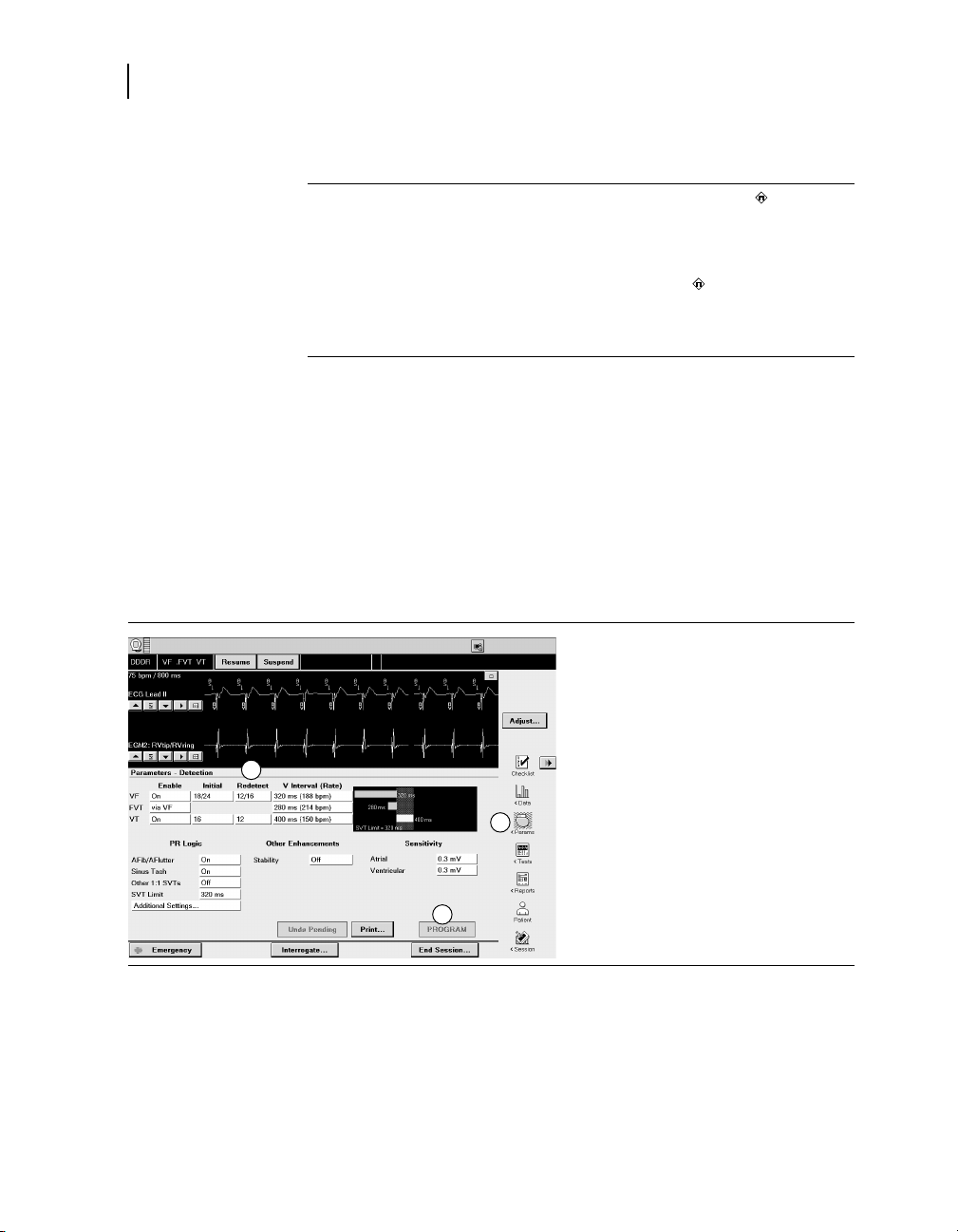
100
1
2
3
Chapter 6
Monitoring episodes for termination or redetection
6.7.1 Parameters
VF Redetect NID – Number of Intervals
to Redetect: number of VF events
the device must count to redetect a
continuing VF after a therapy.
VT Redetect NID – Number of Intervals
to Redetect: number of VT events
the device must count to redetect a
continuing VT after a therapy.
6.7.2 Considerations
Review the following information before programming redetection
parameters.
Initial and Redetect NIDs – You can expedite redetection by
programming the VF and VT Redetect NIDs lower than the Initial
NIDs.
6.7.3 How to program redetection parameters
6/8; 9/12; 12/16
21/28; 24/32; 27/36; 30/40
4; 8; 12
1. Select Params > Detection.
2. Select the desired values for VT
Redetect NID and VF Redetect
NID.
3. Select [PROGRAM].
… 52
; 18/24;
6.7.4 Details about episode termination and redetection
INSYNC SENTRY®7299 Reference Manual
After a therapy is delivered, the device evaluates the ventricular
rhythm to determine if the episode has terminated, is continuing,
or has changed to a different arrhythmia.
 Loading...