


MAXIMO™ DR 7278
Dual Chamber Implantable Cardioverter Defibrillator
Reference Manual
Caution: Federal Law (USA) restricts this device to sale by or on
the order of a physician (or properly licensed practitioner).


MaximoTM DR 7278 0
Reference Manual 0
A guide to the operation and programming
of the Model 7278 MaximoTM DR Dual Chamber
Implantable Cardioverter Defibrillator

The following are trademarks of Medtronic:
Active Can, Cardiac Compass, Checklist, Decision Channel, Flashback, GEM,
Leadless ECG, Marker Channel, Maximo, Medtronic, Patient Alert, PR Logic, Quick
Look, QuickLink, RapidRead, T-Shock

Table of contents
Introduction 11
Abbreviations and acronyms 13
Part I Quick overview
1 Quick reference 17
Physical characteristics 18
Magnet application 19
Longevity projections 19
Replacement indicators 22
Typical charge times 23
High voltage therapy energy 23
Stored data and diagnostics 25
New and enhanced features 27
2 The Maximo DR system 31
System overview 32
Indications and usage 35
Contraindications 35
Patient screening 35
3 Emergency therapy 37
Delivering emergency therapies 38
Part II Device implant and patient follow-up procedures
4 Implanting the ICD 47
Overview 48
Preparing for an implant 48
Replacing an ICD 50
Positioning the leads 51
Testing sensing and pacing thresholds 53
Connecting the leads to the ICD 54
Testing defibrillation operation and effectiveness 55
Positioning and securing the ICD 58
Maximo DR 7278 Reference Manual

6
Table of contents
Completing the implant procedure 59
5 Conducting a patient follow-up session 61
Patient follow-up guidelines 62
Verifying the status of the implanted system 62
Verifying accurate detection and appropriate therapy 63
Verifying effective bradycardia pacing 65
Part III Configuring the ICD for the patient
6 Detecting tachyarrhythmias 69
Detection overview 70
Setting up sensing 73
Detecting VF episodes 78
Detecting VT episodes 82
Detecting FVT episodes 88
Detecting tachyarrhythmia episodes with Combined Count 93
Monitoring episodes for termination or redetection 95
Enhancing detection with PR Logic criteria 98
Enhancing VT detection with the Stability criterion 108
Detecting double tachycardias 111
Detecting prolonged tachyarrhythmias with
High Rate Timeout 112
Key terms 114
7 Treating tachyarrhythmia episodes 119
Treating VF with defibrillation 120
Treating VT and FVT with antitachycardia pacing 130
Treating VT and FVT with cardioversion 140
Optimizing therapy with Smart Mode and Progressive Episode
Therapies 149
Key terms 153
8 Treating bradycardia 157
Providing basic pacing therapy 158
Dual-chamber pacing 164
Single chamber pacing 174
Enhancing pacing for optimal cardiac output 177
Maximo DR 7278 Reference Manual

Table of contents
Adjusting the pacing rate with Mode Switch 190
Preventing competitive atrial pacing 194
Detecting and preventing pacemaker-mediated
tachycardia 199
Providing Ventricular Safety Pacing 203
Providing pacing after high voltage therapies 206
Key terms 208
9 Optimizing charge time and device longevity 213
Optimizing charge time 214
Optimizing device longevity 217
Key terms 218
Part IV Evaluating and managing patient treatment
10 Using the programmer 221
Setting up and using the programmer 222
Display screen features 223
Viewing and programming device parameters 230
Starting and ending patient sessions 234
Viewing live waveform traces 236
Recording live waveform strips 243
Saving and retrieving device data 245
Printing reports 249
Key terms 254
11 Using system evaluation tools 255
A summary of system evaluation tools 256
Taking a quick look at device activity 257
Using the Patient Alert feature 259
Streamlining follow-ups with Checklist 267
Key terms 270
7
12 Setting up and viewing collected data 271
A summary of data collection 272
Setting up data collection 273
Collecting lead performance data 278
Viewing the episode and therapy efficacy counters 279
Maximo DR 7278 Reference Manual

8
Table of contents
Viewing episode data 284
Viewing Flashback Memory 292
Viewing battery and lead status data 294
Viewing lead performance trends 296
Using Cardiac Compass to view long term clinical trends 298
Viewing and entering patient information 305
Automatic device status monitoring 308
Key terms 311
13 Testing the system 315
Testing overview 316
Evaluating the underlying rhythm 316
Measuring pacing thresholds 317
Measuring lead impedance 320
Measuring EGM Amplitude 322
Testing the device capacitors 324
Key terms 326
14 Conducting Electrophysiologic Studies 327
EP Study overview 328
Inducing VF with T-Shock 330
Inducing VF with 50 Hz Burst 334
Inducing an arrhythmia with Manual Burst 337
Inducing an arrhythmia with PES 340
Delivering a manual therapy 343
Key terms 346
15 Solving system problems 349
Overview 350
Solving sensing problems 351
Solving tachyarrhythmia detection problems 353
Solving tachyarrhythmia therapy problems 354
Solving bradycardia pacing problems 355
Responding to device status indicators 357
Key terms 358
Maximo DR 7278 Reference Manual

Part V Appendices
A Warning and precautions 363
General warnings 364
Storage and handling 364
Resterilization 365
Device implantation and ICD programming 365
Lead evaluation and lead connection 367
Follow-up testing 368
Explant and disposal 369
Medical therapy hazards 369
Home and occupational environments 371
BDevice parameters373
Emergency settings 374
Detection parameters 375
Therapy parameters 377
Bradycardia pacing parameters 379
System maintenance parameters 382
Data collection parameters 383
System test and EP study parameters 384
Fixed parameters 387
Patient information parameters 389
Programmer symbols 390
Parameter interlocks 392
Table of contents
9
Index 393
Maximo DR 7278 Reference Manual


Introduction
Using this manual
Before implanting the ICD, it is strongly recommended that you:
■
Refer to the product literature packaged with the ICD for
information about prescribing the ICD.
■
Thoroughly read this manual and the technical manuals for the
leads used with the device.
■
Discuss the procedure and the ICD system with the patient
and any other interested parties, and provide them with any
patient information packaged with the ICD.
Contacting technical support
Medtronic employs highly trained representatives and engineers
located throughout the world to serve you and, upon request, to
provide training to qualified hospital personnel in the use of
Medtronic products.
Introduction
11
In addition, Medtronic maintains a professional staff of consultants
to provide technical consultation to product users. For medical
consultation, Medtronic can often refer product users to outside
medical consultants with appropriate expertise.
For more information, contact your local Medtronic representative,
or call or write Medtronic at the appropriate address or telephone
number listed on the back cover.
Customer education
Medtronic invites physicians to attend an education seminar on
the complete ICD system. The course includes indications for use,
an overview of ICD system functions, implant procedures, and
patient management.
Maximo DR 7278 Reference Manual

12
Introduction
References
Notice
The primary reference for background information is Zacouto FI,
Guize LJ. Fundamentals of Orthorhythmic Pacing. In: Luderitz B,
ed. Cardiac Pacing Diagnostic and Therapeutic Tools. New York:
Springer-Verlag; 1976: 212-218.
See these additional references for more background information:
■
Singer I, Ed. Implantable Cardioverter-Defibrillator. Armonk,
NY: Futura Publishing Co. 1994.
■
Singer I, Barold SS, Camm AJ, Eds. Nonpharmacological
Therapy of Arrhythmias for the 21st Century: The State of the
Art. Armonk, NY: Futura Publishing Co. 1998.
■
Estes M, Manolis AS, Wang P, Eds. Implantable
Cardioverter-Defibrillators. New York, NY: Marcel Dekker, Inc.
1994.
■
Kroll MW, Lehmann MH, Eds. Implantable
Cardioverter-Defibrillator Therapy: The Engineering-Clinical
Interface. Norwell, MA: Kluwer Academic Publishers 1996.
This software is provided as an informational tool for the end user.
The user is responsible for accurate input of patient information
into the software. Medtronic makes no representation as to the
accuracy or completeness of the data input into the software.
MEDTRONIC SHALL NOT BE LIABLE FOR ANY DIRECT,
INDIRECT, INCIDENTIAL OR CONSEQUENTIAL DAMAGES TO
ANY THIRD PARTY WHICH RESULTS FROM THE USE OF THE
INFORMATION PROVIDED IN THE SOFTWARE.
Maximo DR 7278 Reference Manual

Abbreviations and acronyms
A- Atrial
AF Atrial Fibrillation
AFib/AFlutter Atrial Fibrillation and/or Atrial Flutter
ARP Atrial Refractory Period
ATP Antitachycardia Pacing
AVP Atrial Vulnerable Period
BOL Beginning of Life
bpm beats per minute
CNID Combined (VT and VF) Number of Intervals to Detect
CV Cardioversion
DF/Defib Defibrillation
ECG Electrocardiogram
Introduction
13
EGM Electrogram
EOL End of Life
ERI Elective Replacement Indicator
FDI Fibrillation Detection Interval
FTI Fast Ventricular Tachycardia Detection Interval
FVT Fast Ventricular Tachycardia
ICD Implantable Cardioverter Defibrillator
J joules
-1
reciprocal minutes; for example, pacing pulses per minute
min
ms milliseconds
mV millivolts
NCAP Non-Competitive Atrial Pacing
NID Number of Intervals to Detect
NST Non-Sustained Tachycardia
Maximo DR 7278 Reference Manual

14
Introduction
PAC Premature Atrial Contraction
PAV Paced A-V Delay
PES Programmed Electrical Stimulation
PMT Pacemaker-Mediated Tachycardia
P-P an atrial interval
ppm paces or pulses per minute
P-R an interval between a P-wave and the subsequent R-wave
PVAB Post Ventricular Atrial Blanking period
PVARP Post Ventricular Atrial Refractory Period
PVC Premature Ventricular Contraction
RAAV Rate Adaptive A-V delay
RNID Number of Intervals to Redetect
R-P an interval between an R-wave and the subsequent P-wave
R-R a ventricular interval
SAV Sensed A-V Delay
ST/Sinus Tach Sinus Tachycardia
SVT Supraventricular Tachycardia
TDI Tachycardia Detection Interval
V volts
V- Ve n tr ic ul ar
VF Ventricular Fibrillation
VF NID VF Number of Intervals to Detect
VRS Ventricular Rate Stabilization
VSP Ventricular Safety Pacing
VT Ventricular Tachycardia
VT NID VT Number of Intervals to Detect
Maximo DR 7278 Reference Manual

Quick overview
Part I
Maximo DR 7278 Reference Manual


Physical characteristics 18
Magnet application 19
Longevity projections 19
Replacement indicators 22
Typical charge times 23
High voltage therapy energy 23
Stored data and diagnostics 25
New and enhanced features 27
Quick reference1
1
Maximo DR 7278 Reference Manual

18
Chapter 1
Physical characteristics
Physical characteristics
Table 1-1. ICD physical characteristicsa
Volume 39 cc
Mass 76 g
b
H x W x D
Surface area of device can 67 cm
Radiopaque IDc
Materials in contact with
human tissue
d
68 mm x 51 mm x 15 mm
2
PRM
Titanium / polyurethane / silicone rubber
Battery Lithium silver vanadium oxide
Connectors Two IS-1 connectors for pacing and
sensing, Two DF-1 connectors for high
voltage therapy, Active Can electrode
(programmable)
Device Port Connector
Typ e
Software
Name
SVC DF-1 HVX
A
V
SVC
RV
RV DF-1 HVB
Can n/a HVA, Can
V IS-1 bipolar
A IS-1 bipolar
Can
74lead.eps
Suture holes
78Suture.eps
a
Measurements are nominal values based on CAD (computer aided design)
model measurements and are rounded to the nearest unit.
b
Grommets may protrude slightly beyond the can surface.
c
Engineering series number follows the radiopaque code.
d
These materials have been successfully tested for the ability to avoid biological
incompatibility. The device does not produce an injurious temperature in the
surrounding tissue.
Maximo DR 7278 Reference Manual

Magnet application
Bringing a magnet close to the device triggers changes in device
operation as shown in Table 1-2. When the magnet is removed,
the device returns to its programmed operations.
Table 1-2. Effects of magnet application on the device
Pacing mode as programmed
Pacing rate and interval as programmed
VF, VT, and FVT detection suspended
Patient Alert audible tones
(20 seconds or less)
a
Rate response adjustments are suspended while a Patient Alert tone sounds.
b
Detection resumes if telemetry is established and the application software is
running, or it resumes after the application software has started.
c
The Test tone does not sound if “VF Detection/Therapy Off” is the only alert
enabled.
Quick reference
Magnet application
a
b
with programmable alert(s) enabled:
■
continuous tone (Test)
■
on/off intermittent tone (seek follow-up)
■
high/low dual tone (urgent follow-up)
with programmable alerts disabled:
■
no tone
■
high/low dual tone (urgent follow-up)
c
19
Longevity projections
Longevity estimates are based on accelerated battery discharge
data and device modeling with EGM pre-storage off, 60 ppm
-1
(min
) pacing rate, with:
■
2.5 V pacing pulse amplitude, 0.4 ms pacing pulse width, and
35 J delivered therapy energy (see Table 1-3)
■
3 V pacing pulse amplitude, 0.4 ms pacing pulse width, and
35 J delivered therapy energy (see Table 1-4)
■
This model assumes default automatic capacitor formation
setting. As a guideline, each full energy charge decreases
device longevity by approximately 31 days.
Maximo DR 7278 Reference Manual

20
Chapter 1
Longevity projections
Table 1-3. Projected longevity in years with 2.5 V pacing amplitude and
0.4 ms pulse width
a
EGM
pre-storage
500 ohm
b
pacing
impedance
900 ohm
pacing
impedance
Percent
pacing
Maximum
energy
charging
frequency
DDD VVI DDD VVI
0% Semi-Annual Off 8.5 8.5 8.5 8.5
On 8.3 8.3 8.3 8.3
Quarterly Off 7.1 7.1 7.1 7.1
On 7.0 7.0 7.0 7.0
15% Semi-Annual Off 8.1 8.4 8.3 8.5
On 7.9 8.2 8.1 8.3
Quarterly Off 6.9 7.1 7.0 7.1
On 6.7 6.9 6.8 7.0
50% Semi-Annual Off 7.4 8.0 7.9 8.3
On 7.2 7.8 7.7 8.1
Quarterly Off 6.4 6.8 6.7 7.0
On 6.2 6.6 6.5 6.8
100% Semi-Annual Off 6.6 7.5 7.3 8.0
On 6.4 7.3 7.2 7.8
Quarterly Off 5.7 6.4 6.3 6.8
On 5.6 6.3 6.2 6.6
a
Maximum energy charging frequency may include full energy therapy shocks or
capacitor formations.
b
The data provided for programming EGM pre-storage on is based on a 6 month
period (two 3-month follow-up intervals) over the life of the device. Additional
use of EGM pre-storage reduces longevity by approximately 27% or 3 months
per year.
Maximo DR 7278 Reference Manual

Quick reference
Longevity projections
Table 1-4. Projected longevity in years with 3 V pacing amplitude and
0.4 ms pulse width
Percent
pacing
0% Semi-Annual Off 8.5 8.5 8.5 8.5
15% Semi-Annual Off 8.0 8.3 8.2 8.4
50% Semi-Annual Off 7.1 7.8 7.6 8.1
100% Semi-Annual Off 6.1 7.2 6.9 7.8
a
Maximum energy charging frequency may include full energy therapy shocks or
capacitor formations.
b
The data provided for programming EGM pre-storage on is based on a 6 month
period (two 3-month follow-up intervals) over the life of the device. Additional
use of EGM pre-storage reduces longevity by approximately 27% or 3 months
per year.
Maximum
energy
charging
frequency
a
EGM
pre-storage
500 ohm
b
pacing
impedance
900 ohm
pacing
impedance
DDD VVI DDD VVI
On 8.3 8.3 8.3 8.3
Quarterly Off 7.1 7.1 7.1 7.1
On 7.0 7.0 7.0 7.0
On 7.8 8.1 8.0 8.2
Quarterly Off 6.8 7.0 6.9 7.1
On 6.6 6.9 6.8 6.9
On 6.9 7.6 7.4 7.9
Quarterly Off 6.1 6.7 6.5 6.9
On 6.0 6.5 6.4 6.7
On 5.9 7.0 6.8 7.6
Quarterly Off 5.4 6.2 6.0 6.6
On 5.2 6.0 5.9 6.5
21
Maximo DR 7278 Reference Manual

22
Chapter 1
Replacement indicators
Replacement indicators
Battery voltage and messages about replacement status appear
on the programmer display and on printed reports. Table 1-5 lists
the Elective Replacement Indicator (ERI) and the End of Life
(EOL) conditions.
Table 1-5. Replacement indicators
Elective Replacement (ERI) ≤ 2.62 V
End of Life (EOL) 3 months after ERI
ERI date – The programmer displays the date when the battery
reached ERI on the Quick Look and Battery and Lead
Measurements screens.
Temporary voltage decrease – The battery voltage temporarily
decreases following a high voltage charge. If a battery
measurement is taken immediately after a high voltage charge,
the ERI or EOL indicator may be displayed. However, this is a
temporary status which will return to normal when the battery has
recovered from the charge.
EOL indication – If the programmer indicates that the device is at
EOL, replace the device immediately.
Post-ERI conditions – EOL device status is defined as three
months following an ERI indication assuming the following
post-ERI conditions: 100% DDD pacing at 60 ppm, 3 V, 0.4 ms;
500 Ω pacing load; and six 35 J charges. EOL may be indicated
before the end of three months if the device exceeds these
conditions.
Maximo DR 7278 Reference Manual

Typical charge times
The most recent capacitor charge time appears on the
programmer display and on printed reports and can be evaluated
using the Charge/Dump test (see Table 1-6).
Ta b l e 1 - 6 . Ty p ic a la full energy charge times
At Beginning of Life (BOL) 7.0 seconds
At Elective Replacement (ERI) 8.9 seconds
a
These charge times are typical when the capacitors are fully formed.
High voltage therapy energy
The stored energy of the device is derived from the peak capacitor
voltage and is always greater than the energy delivered by the
device. Table 1-7 compares the programmed energy levels
delivered by the device to the energy levels stored in the
capacitors before delivery.
Quick reference
Typical charge times
23
Maximo DR 7278 Reference Manual

24
Chapter 1
High voltage therapy energy
Table 1-7. Comparing delivereda (programmed) and storedb energy levels
Energy (J) Charge
Delivered a/
Stored
b
Programmed
35 39 7.0 10 12 2.0
32 37 6.4 9 10.5 1.8
30 34 6.0 8 9.3 1.6
28 32 5.6 7 8.2 1.4
26 30 5.2 6 7.1 1.2
25 29 5.0 5 5.9 1.0
24 27 4.8 4 4.8 0.8
22 25 4.4 3 3.6 0.6
20 23 4.0 2 2.4 0.4
18 21 3.6 1.8 2.2 0.4
16 19 3.2 1.6 2.0 0.3
15 17 3.0 1.4 1.7 0.3
14 16 2.8 1.2 1.5 0.2
13 15 2.6 1.0 1.2 0.2
12 14 2.4 0.8 1.0 0.2
11 13 2.2 0.6 0.8 0.1
a
Energy delivered at connector block into a 75 ohm load.
b
Energy stored at end of charge on capacitor.
c
Typical charge time at Beginning of Life (BOL) with fully formed capacitors, rounded to the nearest tenth of
a second.
Time
c
(sec)
Delivered a/
Programmed
Energy (J) Charge
Timec (sec)
b
Stored
0.4 0.5 0.1
Maximo DR 7278 Reference Manual

Stored data and diagnostics
Table 1-8. Stored data and diagnostics
Episode data
Tachy episodes 150 VF/VT/FVT episodes: intervals, text, EGM
Quick reference
Stored data and diagnostics
25
EGM capacity for
tachy episodes
14 minutes of dual-channel EGM, or 23.5
minutes of single-channel EGM
SVT/NST episodes 50 SVT/NST episodes: intervals, text, EGM (the
device does not usually store detailed episode
records for NST episodes)
EGM capacity for
SVT/NST episodes
2 minutes of dual-channel EGM, or 3.6 minutes
of single-channel EGM
Brady episodes 53 mode switch episodes
EGM sources 9 options: atrial / ventricular / far-field
EGM options Store before onset; Store during charging
Flashback memory 2000 intervals (containing both A-A and V-V):
before latest VF, before latest VT, and before
interrogation
Counter data
Detection counters Lifetime total, since cleared, and since last
session
Episode counters Episodes:
■
VF, FVT, and VT
■
Atrial Fibrillation / Atrial Flutter episodes
■
Sinus Tach episodes
■
Other 1:1 SVT episodes
■
NST episodes
■
Mode switch episodes
Percentage pacing:
■
AS-VS, AS-VP, AP-VS, AP-VP percentages
Additional counters:
■
Single PVCs and PVC runs
■
Rate stabilization pulses and runs
Maximo DR 7278 Reference Manual

26
Chapter 1
Stored data and diagnostics
Table 1-8. Stored data and diagnostics (continued)
Therapy efficacy
counters
Other stored data
Counts for each VF, FVT, VT Therapy:
■
Delivered
■
Successful
■
Unsuccessful
■
Intervention (manually aborted)
Total number of aborted shocks
Patient Alert events Up to 10 log entries: text and date for the first
time an alert is triggered between interrogations
Battery and lead
measurements
Battery voltage, last capacitor formation, last
charge, lead impedance, EGM amplitude
measurements, last high voltage therapy, and
sensing integrity counter
Lead performance
trends
14 days of daily measurements plus 80 weeks
of weekly minimum and maximum
measurements:
■
Lead impedance: atrial pacing, ventricular
pacing, defibrillation pathway, and SVC
lead (if used)
■
EGM amplitude: atrial (P-waves),
ventricular (R-waves)
Cardiac Compass
trends
14 months of measurement trends:
■
VT and VF episodes per day
■
High voltage therapies delivered per day
■
Ventricular rate during VT or VF
■
Episodes of non-sustained tachycardia per
day
■
Heart rate variability
■
Total daily time in AF or AT
■
Ventricular rate during AF or AT
■
Percent pacing per day
■
Patient activity
■
Average day and night ventricular heart
rate
Maximo DR 7278 Reference Manual

New and enhanced features
The following features are new or changed from the
7275 GEM III DR ICD.
Patient management
RapidRead telemetry – Communication between the device and
programmer is approximately 20 times faster than telemetry in
previous Medtronic ICD devices. The magnitude of improvement
depends on the amount and type of data that is interrogated.
RapidRead telemetry is more reliable and has an increased range
that makes placing the programming head easier.
Cardiac Compass trends report – This report displays up to
14 months of trend data related to tachyarrhythmia episodes,
heart rate, and patient activity. See “Using Cardiac Compass to
view long term clinical trends” on page 298.
Patient Alert – The alert duration when a magnet is applied to the
device is now 20 seconds. The device also provides several
new alerts:
■
SVC (HVX) lead impedance out of range
■
Active Can off without SVC
■
DOO/VOO mode programmed
■
VF Detection programmed off, or fewer than four VF therapies
enabled for at least six hours
■
charge circuit timeout occurred
■
excessive charge time ERI
Quick reference
New and enhanced features
27
For more information, see “Using the Patient Alert feature” on
page 259.
EGM amplitude trends – The device automatically measures
R-wave and P-wave EGM amplitudes every day. These daily
measurements are included in the data displayed on the Lead
Performance Trends screen. See “Setting up data collection” on
page 273.
Maximo DR 7278 Reference Manual

28
Chapter 1
New and enhanced features
EGM amplitude test – You can use the EGM Amplitude test to
measure R-wave and P-wave EGM amplitudes. The results are
reported on the EGM Amplitude Test screen. See “Measuring
EGM Amplitude” on page 322.
Lead impedance measurement for SVC (HVX) – Along with
other lead impedance measurements, the device provides an
independent SVC (HVX) measurement to check the integrity of
the supplementary high voltage electrode. See “Measuring lead
impedance” on page 320.
Leadless ECG signal – If a supplementary high voltage
electrode is placed in the SVC, the device provides the
Leadless ECG signal through either the Can to SVC (HVX) or RV
(HVB) to SVC (HVX) EGM source. See “Setting up data collection”
on page 273.
Expanded pre-onset EGM storage – The device can now store
up to 20 seconds of EGM before a tachycardia starts. See “Setting
up data collection” on page 273.
Smart Auto Cap Formation – When the Auto Cap Formation
Interval is set to Auto, the formation interval automatically adjusts
to optimize device longevity and charge times. See “Smart Auto
Cap” on page 216.
Ending a patient session – The device audits the programmed
parameter settings when you end a patient session and alerts you
if any of the settings are atypical. See “Starting and ending patient
sessions” on page 234.
Tachyarrhythmia detection
VT Monitoring – VT detection can be set to Monitor, which allows
the device to detect and record VT episodes without delivering
therapy or influencing VF detection. See “VT monitoring” on
page 86.
High Rate Timeout – High Rate Timeout can turn off detection
enhancements (Stability, PR Logic criteria) if a high rate episode
is longer than a programmed duration. See “Details about High
Rate Timeout” on page 113.
Maximo DR 7278 Reference Manual

Tachyarrhythmia therapy
Episode confirmation during and after charging – The device
continually monitors the ventricular rhythm during and after
charging for cardioversion or defibrillation (when VF confirmation
is active) to ensure the arrhythmia is present before delivering the
high voltage shock. See “Confirming VF after initial detection” on
page 126 and “Confirming VT or FVT after detection” on
page 144.
Programmable Active Can – If a supplementary electrode is
connected to the SVC (HVX) port, you can deselect the device
Can as a high voltage electrode. See “Delivery pathway
electrodes” on page 123.
Output – The device has a maximum delivered energy of
35 joules.
Bradycardia pacing
Quick reference
New and enhanced features
29
EP studies
Accelerometer-based rate response – The device uses an
accelerometer to provide rate responsive pacing.
Additional bradycardia pacing modes – The device provides
asynchronous pacing in the DOO and VOO pacing modes and
provides the ODO mode to disable pacing. See Chapter 8,
“Treating bradycardia” on page 157.
Enhanced AT-style Mode Switch – Mode Switch episodes are
detected using a combination of the median atrial rate and the AF
evidence criterion. See “Details about Mode Switch” on page 192.
Defibrillation threshold testing support – The T-Shock and
50 Hz Burst induction screens allow you to monitor time between
inductions, program ventricular sensing and VF therapy settings,
adjust induction settings, select manual therapies, and retrieve
episode records after therapy. See “How to perform defibrillation
threshold testing” on page 57.
Maximo DR 7278 Reference Manual

30
Chapter 1
New and enhanced features
Backup VVI pacing during atrial inductions – You can choose
to have the device deliver backup ventricular pacing during Manual
Burst and PES inductions that are delivered to the atrium. See “EP
Study overview” on page 328.
Maximo DR 7278 Reference Manual

System overview 32
Indications and usage 35
Contraindications 35
Patient screening 35
The Maximo DR system2
2
Maximo DR 7278 Reference Manual

32
Chapter 2
System overview
System overview
The Model 7278 Maximo DR Dual Chamber Implantable
Cardioverter Defibrillator (ICD) system is an implantable medical
device system that automatically detects and treats episodes of
ventricular fibrillation, ventricular tachycardia, fast ventricular
tachycardia, and bradyarrhythmia. The ICD system includes three
major components:
■
ICD
The ICD senses the electrical activity of the patient’s heart via
the sensing electrodes of the implanted atrial and ventricular
leads. It then analyzes the heart rhythm based on selectable
sensing and detection parameters. If the ICD detects a
tachyarrhythmia, it delivers defibrillation, cardioversion, or
antitachycardia pacing therapy to the patient’s heart. If the ICD
identifies a bradyarrhythmia, it delivers bradycardia pacing
therapy to the patient’s heart.
■
Leads
The ICD can be used with transvenous or epicardial
defibrillation leads. The lead system should consist of bipolar
or paired unipolar
1
pacing/sensing leads in each chamber of
the heart and one or two high voltage cardioversion/
defibrillation electrodes. You can program the Active Can
device case as a high voltage electrode. The pacing and
sensing electrodes in each chamber sense cardiac activity
and deliver pacing stimuli.
■
Programmer and software
The Medtronic programmer and 9978 application software
allow you to perform the following tasks:
■
configure the detection, therapy, and bradycardia features
for your patient
■
perform electrophysiological studies and system tests
■
monitor, display, or print patient cardiac activity
information
■
view patient and device diagnostic data
1
With an appropriate unipolar to bipolar adapter kit.
Maximo DR 7278 Reference Manual

The Maximo DR devices and 9978 application software are
compatible with the following programmer systems:
■
Medtronic CareLink Model 2090 programmer with a Model
2067 or 2067L programming head
■
Medtronic Model 9790C programmer with a Model 9767 or
9767L programming head
For information about:
■
indications, contraindications, lead compatibility, warnings
and precautions, and patient selection, see the Maximo DR
7278 Implant Manual, which accompanies each device.
■
basic programmer and software desktop functions that are not
included in Chapter 10, “Using the programmer” on page 221,
see the manual accompanying the programmer.
■
installing the programming head, see the manual
accompanying the programming head.
■
implanting leads, refer to the manuals accompanying
the leads.
Detecting and treating tachyarrhythmias
The Maximo DR system
System overview
33
The ICD monitors the cardiac rhythm for short ventricular intervals
that may indicate the presence of VF, VT, or FVT.
■
Upon detection of VF, the ICD delivers a biphasic defibrillation
shock of up to 35 joules. If the VF episode persists, up to five
more individually programmed defibrillation shocks can be
delivered.
■
Upon detection of VT, the ICD delivers either a Ramp, Ramp+,
or Burst antitachycardia pacing therapy or a biphasic
cardioversion shock of up to 35 joules synchronized to a
ventricular depolarization. If the VT episode persists, up to five
more individually programmed VT therapies can be delivered.
You can also program the ICD to monitor the VT episode
without delivering therapy.
■
Upon detection of FVT, the ICD delivers either a Ramp,
Ramp+, or Burst antitachycardia pacing therapy or a biphasic
cardioversion shock of up to 35 joules synchronized to a
ventricular depolarization. If the FVT episode persists, up to
five more individually programmed FVT therapies can be
delivered.
Maximo DR 7278 Reference Manual

34
Chapter 2
System overview
You can program the ICD to distinguish between true ventricular
arrhythmias and rapidly conducted supraventricular tachycardia
(SVT) and withhold therapy for SVT.
You can also program the ICD to detect a double tachycardia (an
unrelated ventricular arrhythmia occurring simultaneously with an
SVT), so that therapy is not withheld for a ventricular arrhythmia in
the presence of an SVT.
Treating bradycardia
The ICD provides dual chamber rate responsive bradycardia
pacing to optimize hemodynamics. An internal accelerometer
senses the patient’s physical activity, allowing the ICD to increase
and decrease the pacing rate in response to changes in the level
of activity.
Monitoring for real-time and stored data
The ICD and programmer provide real-time information on
detection and therapy parameters and status during a patient
session. The ICD also provides accumulated data on device
operation, including stored electrograms, detected and treated
tachyarrhythmia episodes, bradycardia interventions, and the
efficacy of therapy. The Cardiac Compass report provides up to 14
months of clinically significant data, including arrhythmia
episodes, therapies delivered, physical activity, heart rate, and
bradycardia pacing activities.
All of this information can be printed and retained in the patient’s
file or saved in electronic format on a floppy diskette.
Conducting electrophysiologic tests
You can use the system to conduct non-invasive
electrophysiologic studies including manual delivery of any of the
ICD therapies to manage an induced or spontaneous
tachyarrhythmia.
Alerting the patient to system events
You can use the programmable Patient Alert monitoring feature to
notify the patient with audible tones if certain conditions related to
the leads, battery, charge time, and therapies occur. The patient
can then respond based on your prescribed instructions.
Maximo DR 7278 Reference Manual

Indications and usage
The Model 7278 Maximo DR system is intended to provide
ventricular antitachycardia pacing and ventricular defibrillation for
automated treatment of life threatening ventricular arrhythmias.
Contraindications
The Maximo DR system is contraindicated for
■
patients whose tachyarrhythmias may have transient or
reversible causes, such as acute myocardial infarction,
digitalis intoxication, drowning, electrocution, electrolyte
imbalance, hypoxia, or sepsis.
■
patients with incessant VT or VF
■
patients who have a unipolar pacemaker
■
patients whose primary disorder is bradyarrhythmias or atrial
arrhythmias
The Maximo DR system
Indications and usage
35
Patient screening
Prior to implant, patients should undergo a complete cardiac
evaluation, including electrophysiologic testing. Also,
electrophysiologic evaluation and testing of the safety and efficacy
of the proposed tachyarrhythmia therapies are recommended
during and after the implantation of the device.
Other optional screening procedures could include exercise stress
testing to determine the patient’s maximum sinus rate, and cardiac
catheterization to determine if there is a need for concomitant
surgery and/or medical therapy.
Maximo DR 7278 Reference Manual


Emergency therapy3
Delivering emergency therapies 38
How to deliver emergency 35 joule defibrillation 40
How to deliver emergency cardioversion 41
How to deliver emergency fixed burst pacing 42
How to deliver emergency VVI pacing 44
3
Maximo DR 7278 Reference Manual

38
Chapter 3
Delivering emergency therapies
Delivering emergency therapies
The device provides the following emergency therapies:
■
defibrillation
■
cardioversion
■
fixed burst pacing
■
emergency VVI pacing
The default emergency therapy is 35 joule defibrillation. When you
select [Emergency] and [DELIVER], the device charges and
delivers a biphasic 35 joule shock along the AX>B pathway
The programmer resets the emergency defibrillation energy to
35 joules each time you select [Emergency]. Emergency
cardioversion and fixed burst values remain as selected for the
duration of the session.
To return to other programming functions from an Emergency
screen, select [Exit Emergency].
Effect on system operation
1
.
The device suspends the automatic detection features when
emergency defibrillation, cardioversion, or fixed burst pacing
therapies are delivered. Detection is not suspended during
emergency VVI pacing. Removing the programming head or
pressing [Resume] turns detection on again.
Aborting an emergency therapy
As a safety precaution, the programmer also displays an [ABORT]
button which immediately terminates any emergency therapy in
progress.
1
If Active Can is turned off, the defibrillation is delivered between the HVX and
HVB electrodes.
Maximo DR 7278 Reference Manual

Emergency therapy
Delivering emergency therapies
Mechanical Emergency buttons on the Model 9790C programmer
If you press the red mechanical [Emergency] button on the
programmer display panel, the programmer displays the
Emergency screen. The mechanical yellow-on-blue [Deliver]
button activates the emergency therapy displayed on the
programmer screen. This button functions only when the
Emergency screen is displayed.
Mechanical Emergency VVI button on the CareLink Model 2090
programmer
If you press the red Emergency VVI button on the programmer
display panel, the device initiates Emergency VVI pacing and the
programmer displays the Emergency screen.
Temporary parameter values
39
Emergency tachyarrhythmia therapies use temporary values that
1
do not change the programmed parameters of the device.
These
values are not in effect until you select [DELIVER]. After the
tachyarrhythmia therapy is complete, the device reverts to its
programmed values.
1
Delivery of Emergency VVI Pacing changes the programmed bradycardia
pacing values to the emergency values (see page 43).
Maximo DR 7278 Reference Manual
40
Chapter 3
Delivering emergency therapies
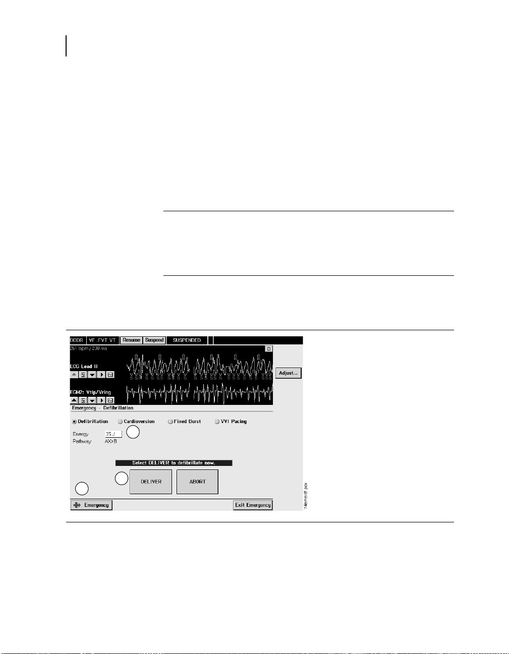
Delivering an emergency defibrillation therapy
The default emergency therapy is a full-energy defibrillation.
When you select [Emergency] and [DELIVER], the device charges
and delivers a biphasic full-energy shock. The programmer resets
the emergency defibrillation energy to its maximum value each
time you select [Emergency] or select the [Defibrillation] option
from an Emergency screen.
Parameters
Energy – Amount of energy delivered to the
heart by the therapy.
* Medtronic nominal setting
10, 11, ... 16
18, 20, 22, 24, 25,
26, 28, 30, 32, 35*J
Pathwaya – Direction the electrical current flows
through the heart.
a
If Active Can is Off, the HVA (Can) electrode is not used as part of the
high-energy delivery pathway.
How to deliver emergency 35 joule defibrillation
3
4
2
AX>B (fixed)
1. Position the programming
head over the device.
2. Select [Emergency].
3. Accept the defibrillation
energy shown on the screen,
or select Energy and select a
new value from the window.
4. Select [DELIVER].
If delivery is not confirmed,
verify that the programming
head is properly positioned
and select [Retry] or [Cancel].
Maximo DR 7278 Reference Manual

Delivering emergency therapies
Delivering an emergency cardioversion therapy
When you initiate an emergency cardioversion therapy, the device
charges its capacitors to the selected energy and attempts to
deliver therapy synchronized with a sensed tachyarrhythmia event.
If the cardioversion therapy cannot be synchronized, it is aborted.
See “Synchronizing cardioversion after charging” on page 145.
Parameters
Energy – Amount of energy delivered to the
heart by the therapy.
a
Pathway
through the heart.
a
If Active Can is Off, the HVA (Can) electrode is not used as part of the
high-energy delivery pathway.
– Direction the electrical current flows
How to deliver emergency cardioversion
3
4
5
2
Emergency therapy
* Medtronic nominal setting
0.4, 0.6, ...1.8,
2, 3, ... 16
18, 20, 22, 24, 25,
26, 28, 30, 32, 35*J
AX>B (fixed)
1. Position the programming
head over the device.
2. Select [Emergency].
3. Select [Cardioversion].
4. Accept the cardioversion
energy shown on the screen,
or select Energy and select a
new value from the window.
5. Select [DELIVER].
If delivery is not confirmed,
verify that the programming
head is properly positioned
and select [Retry] or [Cancel].
41
Maximo DR 7278 Reference Manual
42
Chapter 3
Delivering emergency therapies
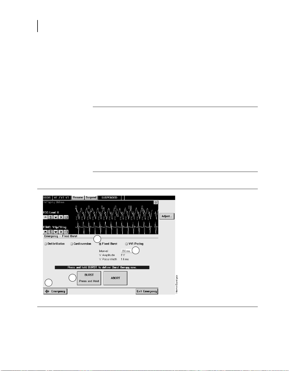
Delivering emergency fixed burst pacing
Emergency fixed burst pacing delivers maximum output pacing
pulses to the ventricle at a selectable interval. The therapy
continues for as long as you keep the programmer stylus on the
[BURST Press and Hold] button.
Parameters
How to deliver emergency fixed burst pacin
Interval – Time interval between pacing
pulses delivered during the fixed burst
therapy.
V. Amplitude – Voltage of the ventricular
pacing pulses delivered during the fixed
burst therapy.
V. Pulse Width – Duration of the
ventricular pacing pulses delivered during
the fixed burst therapy.
How to deliver emergency fixed burst pacing
3
4
2
5
* Medtronic nominal setting
100, 110, ... 350*
360, 370, ... 600 ms
8V(fixed)
1.6 ms (fixed)
1. Position the programming
head over the device.
2. Select [Emergency].
3. Select [Fixed Burst].
4. Accept the pacing interval
shown on the screen, or
select Interval for a new
interval value.
5. Select [BURST Press and
Hold].
If delivery is not confirmed,
the programmer displays
an error window. Verify that
the programming head is
properly positioned. Select
[OK] from the window and
reselect [BURST Press and
Hold].
Maximo DR 7278 Reference Manual

Enabling emergency VVI pacing
Emergency VVI pacing programs the device to deliver high-output
ventricular pacing. You can initiate emergency VVI pacing from
the Emergency screen or by pressing the red mechanical button
on the programmer display panel and selecting VVI Pacing on the
screen. To disable emergency VVI pacing, reprogram the
bradycardia pacing parameters from the Parameters screen.
Emergency therapy
Delivering emergency therapies
43
Parameters
How to deliver emergency fixed burst pacin
Pacing Mode– NBG Codea for the pacing
VVI
mode provided during emergency VVI
pacing.
Lower Rate – Minimum pacing rate to
70 min
-1
maintain adequate heart rate during
periods of inactivity.
V. Amplitude – Voltage of the ventricular
6V
pacing pulses delivered during emergency
VVI pacing.
V. Pulse Width – Duration of the
1.6 ms
ventricular pacing pulses delivered during
emergency VVI pacing.
V. Pace Blanking – Time interval during
240 ms
which sensing is disabled after a pacing
pulse.
Hysteresis – Enables tracking of intrinsic
Off
heart rate below programmed Lower Rate
to prevent pacing during extended periods
of inactivity, such as when a patient is
sleeping.
V. Rate Stabilization – Modifies the
Off
pacing rate to eliminate the long pause
that typically follows a premature
ventricular contraction.
a
N–North American Society of Pacing and Electrophysiology (NASPE), B–British
Pacing and Electrophysiology Group (BPEG), G–Generic Pacemaker Code
Maximo DR 7278 Reference Manual

44
Chapter 3
Delivering emergency therapies
How to deliver emergency VVI pacing
4
2
1. Position the programming
head over the device.
2. Select [Emergency].
3. Select [VVI Pacing].
4. Select [PROGRAM]. A
successful programming
3
sets the device to the
following maximum output
bradycardia pacing values.
■
Pacing Mode: VVI
■
Lower Rate: 70 ppm
-1
(70 min
■
V. Amplitude: 6 V
■
V. Width: 1.6 ms
■
V. Pace Blanking: 240 ms
■
Hysteresis: Off
■
V. Rate Stabilization: Off
)
If programming is not
confirmed, verify that the
programming head is properly
positioned and select [Retry]
or [Cancel].
Maximo DR 7278 Reference Manual

Part II
Device implant and patient follow-up procedures
Maximo DR 7278 Reference Manual


Implanting the ICD4
Overview 48
Preparing for an implant 48
Replacing an ICD 50
Positioning the leads 51
Testing sensing and pacing thresholds 53
Connecting the leads to the ICD 54
Testing defibrillation operation and effectiveness 55
Positioning and securing the ICD 58
Completing the implant procedure 59
4
Maximo DR 7278 Reference Manual

48
Chapter 4
Overview
Overview
Preparing for an implant
The tasks for implanting an ICD include
1. Preparing for an implant
2. Replacing an ICD
3. Positioning the leads
4. Testing sensing and pacing thresholds
5. Connecting the leads to the ICD
6. Testing defibrillation operation and effectiveness
7. Positioning and securing the ICD
8. Completing the implant procedure
These tasks are described in the sections that follow.
Warning: Keep a back-up external defibrillator available
during the implant for transthoracic rescue when arrhythmias
are induced.
Equipment for an implant
The equipment that is needed for an implant is as follows:
■
Medtronic CareLink Model 2090 programmer with a
Model 2067 or 2067L programming head, or a Model 9790C
programmer with a Model 9767 or 9767L programming head
■
Maximo Model 9978 software application
■
Model 2290 or 8090 Analyzer lead analysis device or
equivalent pacing system analyzer
■
external defibrillator
Maximo DR 7278 Reference Manual

Sterile supplies for an implant
The sterile supplies that are needed for an implant are as follows:
■
implantable device and lead system components
■
programming head sleeve or programming head
■
analyzer cables
■
lead introducers appropriate for the lead system
■
extra stylets of appropriate length and shape
How to prepare for implanting
Set up the programmer and start the application
1. Set up the programmer as described in the instructions provided
with the programmer.
2. Install the Maximo DR Model 9978 software on the programmer, if it
is not already installed.
3. Place the programming head over the device and start the
application. Select the device model or select [Auto identify].
Note: The programmer automatically interrogates the device when
the application starts.
Implanting the ICD
Preparing for an implant
49
Preprogram the device
Before opening the sterile package, prepare the ICD for implant as
follows:
1. Check the “use by” date printed on the package. Do not implant the
device after the “use by” date because the battery’s longevity could
be reduced.
2. Interrogate the ICD, and print a full summary report.
3. Confirm that the battery voltage is at least 3.0 V at room
temperature.
a
If the device has been exposed to lower temperatures or has
delivered a recent high voltage charge, the battery voltage will be
temporarily lower.
4. Set up data collection parameters and the ICD internal clock (see
page 275).
5. Perform a manual capacitor formation (see page 324).
6. Program the therapy and pacing parameters to values appropriate
for the patient (see page 161). Ensure that all tachyarrhythmia
detection is programmed Off (see page 72).
a
Use the Quick Look screen to verify the voltage, see page 257.
Maximo DR 7278 Reference Manual

50
Chapter 4
Replacing an ICD
Replacing an ICD
If you are replacing a previously implanted ICD, turn off ICD
detection and therapies before explanting.
When implanting the ICD with a chronic lead system, perform the
following evaluations to ensure appropriate detection and therapy:
■
Check the integrity of the chronic high voltage leads with a test
shock, chest X-ray, and inspection.
■
Perform chronic pacing and sensing measurements.
■
Measure high voltage lead impedances.
■
Test defibrillation efficacy.
■
Confirm adequate sensing during VF.
■
Ensure proper fit of the lead connectors in the ICD connector
block.
Notes:
■
To meet the implant requirements, it may be necessary to
reposition or replace the chronic leads or to add a third high
voltage electrode.
■
Any unused leads that remain implanted must be capped.
How to explant and replace an ICD
1. Program all tachyarrhythmia detection Off.
2. Dissect the leads and the ICD free from the surrounding tissues in
the surgical pocket. Be careful not to nick or breach the lead
insulation during the process of exposing the system.
3. Loosen each setscrew, and gently retract the lead from the
connector block.
4. Remove the ICD from the surgical pocket.
5. If the connector pin of any implanted lead shows signs of pitting or
corrosion, replace the implanted lead with a new lead. The
damaged lead should be discarded and replaced to assure the
integrity of the device system.
6. Measure sensing, pacing, and defibrillation efficacy using the
replacement ICD.
7. Evaluate the defibrillation efficacy of the replacement system.
Maximo DR 7278 Reference Manual

Positioning the leads
Implant endocardial leads according to the supplied instructions,
unless suitable chronic leads are already in place. Do not use any
lead with this device without first verifying connector compatibility
(refer to the Maximo DR 7278 Implant Manual). Transvenous or
epicardial leads may be used. A bipolar atrial lead with closely
spaced pacing and sensing electrodes is recommended.
Using transvenous leads
Use standard transvenous implant techniques to position the
ventricular lead tip in the right ventricular apex and the atrial
pacing lead tip high on the right atrial appendage.
Follow the general guidelines below for initial positioning of other
transvenous leads (the final positions are determined by
defibrillation efficacy tests):
■
SVC (HVX) lead: Place the lead tip high in the innominate
vein, approximately 5 cm proximal to the right atrium (RA) and
SVC junction.
■
SQ patch: Place the patch along the left mid-axillary, centered
over the fourth-to-fifth intercostal space.
■
CS lead: Advance the lead tip to just under the left atrial
appendage, if possible.
Implanting the ICD
Positioning the leads
51
If using a subclavian approach, position the lead laterally to avoid
pinching the lead body between the clavicle and the first rib.
Warning: Pinching the lead can damage the lead conductor
or insulation, which may cause unwanted high voltage
therapies or result in the loss of sensing or pacing therapy.
Maximo DR 7278 Reference Manual

52
Chapter 4
Positioning the leads
Using epicardial leads
A variety of surgical approaches can be used to implant epicardial
leads, including a limited left thoracotomy or median sternotomy.
A typical placement may use an anterior right ventricular patch as
the RV (HVB) and a posterolateral left ventricular patch as SVC
(HVX).
Follow the general guidelines below for positioning epicardial
leads:
■
If unipolar epicardial pacing leads are used, position the
electrodes about 1 to 2 cm apart to reduce electromagnetic
interference, and route the leads together with several loose
twists.
■
Suture the smooth face of each patch lead against the
epicardium or pericardium in locations that produce optimal
defibrillation.
■
Place the patches so that they encompass the maximum
amount of cardiac mass and they have approximately equal
amounts of mass between them.
■
Ensure that the patches do not overlap and the electrode
portions do not touch.
■
Avoid placing extra-pericardial patches over the phrenic
nerve.
Surgical incisions
A single-incision submuscular or subcutaneous approach is
recommended when the ICD is implanted in the pectoral region.
Make the implant pocket about 1.5 times the size of the ICD.
Submuscular implant – An incision extending over the
deltoid-pectoral groove typically provides access to the cephalic
and subclavian veins as well as the implant pocket. Place the ICD
sufficiently medial to the humeral head to avoid interference with
shoulder motion.
Subcutaneous implant – A transverse incision typically permits
isolation of the cephalic vein. Place the ICD far medially to keep
the leads away from the axilla. Make sure that the upper edge of
the ICD remains inferior to the incision.
Maximo DR 7278 Reference Manual

Testing sensing and pacing thresholds
Testing sensing and pacing thresholds
Sensing and pacing tests include the following measurements:
■
EGM amplitude
■
slew rate
■
pacing threshold
■
pacing lead impedance
Medtronic recommends that you use a Model 2290 or 8090
Analyzer lead analysis device to perform sensing and pacing
measurements. If you use a Pacing System Analyzer (PSA),
perform both atrial and ventricular measurements via the
ventricular channel of the PSA.
Refer to the technical manual for the Analyzer you use to find
details on performing sensing and pacing measurements.
Parameters
Measured sensing and pacing values must meet the following
specific requirements at implant.
Implanting the ICD
53
Considerations
Table 4-1. Sensing and pacing values at implant
Measurement Acute Transvenous Leads Chronic Leads
R- wave amplitude ≥ 5 mV ≥ 3 mV
P- wave amplitude ≥ 2 mV ≥ 1 mV
Slew rate:
atrial ≥ 0.5 V/s ≥ 0.3 V/s
ventricular ≥ 0.75 V/s ≥ 0.5 V/s
a
Capture threshold
atrial ≤ 1.5 V ≤ 3.0 V
ventricular ≤ 1.0 V ≤ 3.0 V
a
At 0.5 ms pulse width
:
When measuring sensing and pacing values, measure between
the tip (cathode) and ring or coil (anode) of each bipolar
pacing/sensing lead.
Maximo DR 7278 Reference Manual

54
Chapter 4
Connecting the leads to the ICD
For unipolar epicardial pacing leads, either electrode can be the
cathode; use the configuration that yields the lower pacing
threshold.
Note: Do not measure the intracardiac EGM telemetered from the
ICD to assess sensing.
Connecting the leads to the ICD
For more detailed information about lead/connector compatibility,
see the Maximo DR 7278 Implant Manual, or contact Medtronic
Technical Services at 1-800-723-4636.
Table 4-2. Lead connections
A
V
Can
SVC
RV
Device
Port
SVC DF-1 HVX
RV DF-1 HVB
Can n/a HVA, Can
V IS-1 bipolar
74lead.eps
A IS-1 bipolar
Connector
Type
Software Name
Warning: Loose lead connections may result in inappropriate
sensing and failure to deliver necessary arrhythmia therapy.
Caution: Use only the torque wrench supplied with the device.
It is designed to prevent damage to the device from
overtightening a setscrew.
For easier lead insertion, insert the ventricular IS-1 leg before
the other legs.
Maximo DR 7278 Reference Manual

Testing defibrillation operation and effectiveness
How to connect the lead to the device
1
a
2
b
74SetScrew.eps
74LeadTIp.eps
Implanting the ICD
1. Insert the torque wrench into the
appropriate setscrew.
a. If the port is obstructed, retract the
setscrew to clear it. Take care not to
disengage the setscrew from the
connector block.
b. Leave the torque wrench in the setscrew
until the lead is secure. This allows a
pathway for venting trapped air when the
lead is inserted.
2. Push the lead or plug into the connector
port until the lead pin is clearly visible in the
pin viewing area. No sealant is required, but
sterile water may be used as a lubricant.
3. Tighten the setscrew by turning clockwise
until the torque wrench clicks.
4. Tug gently on the lead to confirm a secure
fit. Do not pull on the lead until all setscrews
have been tightened.
5. Repeat these steps for each lead.
55
Testing defibrillation operation and effectiveness
Demonstrate reliable defibrillation effectiveness with the
implanted lead system by using your preferred method to
establish that a 10 J (minimum) safety margin exists.
Note: If the 10 J (minimum) safety margin cannot be ensured, see
“Solving tachyarrhythmia therapy problems” on page 354.
High voltage implant values
Measured values must meet the following requirements at
implant.
Table 4-3. High voltage therapy values at implant
Measurement Acute or Chronic Leads
V. Defib impedance
SVC (HVX) impedance (if applicable)
Defibrillation threshold
20 - 200 ohms
20 - 200 ohms
≤ 25 J
Maximo DR 7278 Reference Manual

56
Chapter 4
Testing defibrillation operation and effectiveness
Warning: Ensure that an external defibrillator is charged for a rescue
shock.
How to prepare for defibrillation threshold testing
1. Place the programming head over the ICD, start a patient session,
and interrogate the device, if you have not already done so.
2. Observe the Marker Channel telemetry annotations and the
programmer ECG display to verify that the ICD is sensing properly.
3. Conduct a manual Lead Impedance Test
lead connections. Perform this test with the ICD in the surgical
pocket and keep the pocket very moist. If the impedance is out of
range, perform one or more of the following tasks:
■
Recheck lead connections and electrode placement.
■
Repeat the measurement.
■
Inspect the bipolar EGM for abnormalities.
■
Measure the defibrillation impedance with a manual test shock.
4. Program the ICD to properly detect VF with an adequate safety
margin (1.2 mV sensitivity).
a
See “Measuring lead impedance” on page 320.
a
to verify the defibrillation
Maximo DR 7278 Reference Manual
Testing defibrillation operation and effectiveness
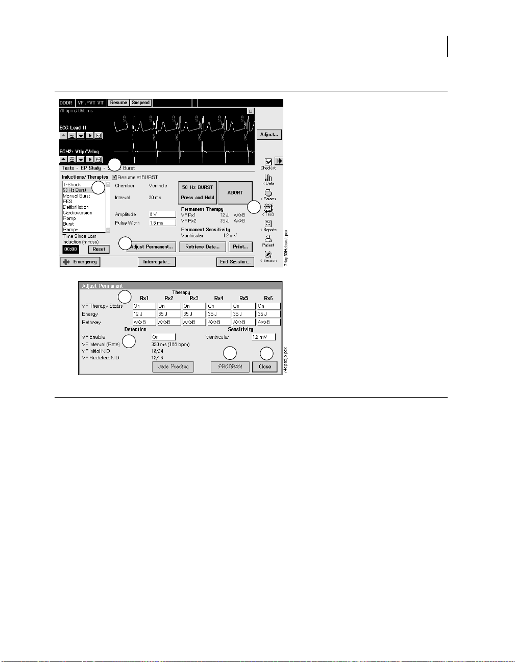
How to perform defibrillation threshold testing
3
2
1
4
6
5
7
8
Implanting the ICD
1. Select Tests > EP Study.
2. Select either 50 Hz BURST or
T-shock induction.
3. Select [Resume at BURST] or
[Resume at DELIVER].
4. Select [Adjust Permanent...].
5. Program VF Enable On.
6. Program the automatic therapy
energy settings. Therapies 2-6
should be set to the maximum
energy.
7. Select [Program].
8. Select [Close].
57
Maximo DR 7278 Reference Manual

58
Chapter 4
Positioning and securing the ICD
11
9
12
13
10
14
9. If performing a T-Shock
induction, select the [Enable]
checkbox.
10. Select [DELIVER], or [50 Hz
BURST Press and Hold].
If necessary, you can abort an
induction or therapy in progress
by pressing [ABORT].
11. Observe the live rhythm monitor
for proper post-shock sensing.
12. Use the [Adjust Permanent...]
button to program the energy
level.
13. Wait until the on-screen timer
reaches 5 minutes, then repeat
steps 9 through 12 as desired.
14. Select Params > Detection and
program VF, FVT, and VT
detection Off before closing.
Positioning and securing the ICD
Cautions: If no SVC electrode is implanted, the pin plug
provided with the device must be secured in the SVC port.
Program tachyarrhythmia detection Off before closing.
How to position and secure the device
Suture Hole Locations
Maximo DR 7278 Reference Manual
1. Ensure that each lead pin or plug is fully
inserted into the connector block and that all
setscrews are tight.
2. Coil any excess lead length beneath the device.
Avoid kinks in the lead conductors.
3. Implant the device within 5 cm of the skin. This
position optimizes the ambulatory monitoring
operations.
4. Suture the device securely within the pocket to
78Suture.eps
minimize post-implant rotation and migration of
the device. Use a surgical needle to penetrate
the suture holes.

Completing the implant procedure
After implanting the device, X-ray the patient to verify the device
and leads placement. To complete programming the device, select
parameters that are appropriate for the patient.
How to complete programming the device
1. After closing the pocket, program detection On. Program ventricular
tachyarrhythmia therapies On as desired.
2. Do not enable the Other 1:1 SVTs PR Logic detection criterion until
the atrial lead has matured (approximately one month post implant).
3. Monitor the patient after the implant, and take X-rays as soon as
possible to document and assess the location of the leads.
4. Program patient information. See “How to view and enter new patient
information” on page 307.
5. Configure the Patient Alert feature. See “Using the Patient Alert
feature” on page 259.
6. Set up data collection parameters. See “Setting up data collection” on
page 273.
7. Interrogate the device after any spontaneous episodes to evaluate
the detection and therapy parameter settings.
8. If the patient has not experienced spontaneous episodes, you may
induce the clinical tachyarrhythmias using the non-invasive EP Study
features to further assess the performance of the system. See
Chapter 14, “Conducting Electrophysiologic Studies” on page 327.
9. Recheck pacing and sensing values, and adjust if necessary.
Implanting the ICD
Completing the implant procedure
59
Maximo DR 7278 Reference Manual


Conducting a patient follow-up
Patient follow-up guidelines 62
Verifying the status of the implanted system 62
Verifying accurate detection and appropriate therapy 63
Verifying effective bradycardia pacing 65
session
5
5
Maximo DR 7278 Reference Manual

62
Chapter 5
Patient follow-up guidelines
Patient follow-up guidelines
Schedule regular patient follow-up sessions to monitor the
condition of the ICD and leads and to verify that the ICD is
configured appropriately for your patient.
During the first few months after receiving a new device, the
patient may require close monitoring. Schedule an office visit at
least every three months.
The Quick Look screen, which is displayed after you interrogate
the device, provides a good beginning for the follow-up review.
Using this screen you can
■
verify that the device is functioning correctly.
■
review the clinical performance and long term trends.
■
print appropriate reports1 to compare the results to the
patient’s history and to retain for future reference.
Note: The Checklist feature provides a standard list of tasks to
perform at a complete follow-up visit. You can also customize your
own checklists if you wish. See “Streamlining follow-ups with
Checklist” on page 267 for more information.
Verifying the status of the implanted system
To verify that the ICD and leads are functioning correctly, review
the following information from the Quick Look screen and perform
follow-up tests as indicated:
■
Review the displayed battery voltage for comparison to the
Elective Replacement Indicator value (see page 22).
Remember that battery voltage may be low if high voltage
charging has occurred within 24 hours.
■
Review the last full energy charge.
– For information about adjusting the capacitor formation
interval, see “Optimizing charge time” on page 214.
– If the programmer displays an Excessive Charge Time ERI,
the ICD should be replaced immediately.
1
See “Using Cardiac Compass to view long term clinical trends” on page 298 for
information on this new report.
Maximo DR 7278 Reference Manual

Conducting a patient follow-up session
Verifying accurate detection and appropriate therapy
■
Review the defibrillation and pacing lead impedance values for
inappropriate values or large changes since the last follow-up.
See “Measuring lead impedance” on page 320.
■
Perform an EGM Amplitude test in each chamber for
comparison to previous EGM Amplitude measurements. See
“How to perform an EGM Amplitude test” on page 323.
■
To review longer term trends in sensing and impedance
measurements, select the [>>] button from the lead
impedance area of the Quick Look screen. The programmer
displays a detailed history of automatic sensing and
impedance measurements. See “Taking a quick look at device
activity” on page 257.
Verifying accurate detection and appropriate therapy
To verify that the ICD is providing effective tachyarrhythmia
detection and therapy, review the following information from the
Quick Look screen and investigate as indicated:
■
Review Quick Look Observations that relate to patient history
and device operation. To display more detailed information
about any observation, select the observation and then select
the [>>] button.
■
Review any Patient Alerts listed in the Observations of the
Quick Look screen. For the most detailed information about
Patient Alerts, select Patient Alert from the Data icon and
select [Events].
■
Check stored episode records for appropriate sensing and
detection of arrhythmias. See “Viewing episode data” on
page 284.
■
Check stored SVT episode records for appropriate
identification of SVTs.
63
Considerations
Review the following information before verifying detection and
therapy.
Flashback memory – In addition to the episode text and stored
electrograms, use Flashback memory and interval plots to help
investigate the accuracy and specificity of ventricular detection.
Maximo DR 7278 Reference Manual

64
Chapter 5
Verifying accurate detection and appropriate therapy
Episode misidentification – If the episode records indicate that
false detections have occurred, the Sensing Integrity counter may
help in determining the prevalence of oversensing. For more
information, see “Sensing integrity counter” on page 279.
If the ICD is oversensing, consider these programming options:
■
Increase the Pace Blanking value.
■
Increase the sensitivity threshold.
Caution: Do not re-program the ICD to decrease oversensing
without assuring that appropriate sensing is maintained. See
“Setting up sensing” on page 73.
If the episode records reveal that a stable monomorphic VT has
been identified and treated as VF, consider these options to
improve the detection accuracy:
■
Review the Interval Plot for the episode, and adjust
VF Interval, if necessary. Use caution when reprogramming
the VF Interval, because changes to this value can adversely
affect VF detection.
■
Consider enabling FVT via VF detection. See “Detecting FVT
episodes” on page 88.
If the SVT episode records include episodes of true VT, review the
SVT episode record to identify the SVT detection criterion that
withheld detection. Adjust the SVT detection criteria parameters
as necessary. See “Enhancing detection with PR Logic criteria” on
page 98, and “Enhancing VT detection with the Stability criterion”
on page 108.
Maximo DR 7278 Reference Manual

Conducting a patient follow-up session
Verifying effective bradycardia pacing
Verifying effective bradycardia pacing
To verify that the ICD is sensing and pacing appropriately, review
the following information from the Quick Look screen and
investigate as indicated:
■
Confirm that the patient is receiving adequate cardiac support
for daily living activities.
■
Review the pacing conduction history for comparison to the
patient history. A sharp increase in the paced beats
percentage may indicate a need for investigation and analysis.
■
Review the recorded Mode Switch episodes for comparison to
the patient’s atrial arrhythmia history. A dramatic increase in
frequency or duration of atrial episodes may indicate a need
for investigation and analysis.
To display more detailed information about the Mode Switch
episodes, perform these steps: select Episodes and Counters
from the Data icon; select the Mode Switch episodes from the
listed episode counters; then select the [Open Data] button.
■
Review the Cardiac Compass report for comparison to patient
history (see page 298).
■
Conduct pacing threshold tests (see page 317) to verify that
the programmed pacing outputs provide a sufficient
safety margin.
65
Considerations
Review the following information before verifying bradycardia
pacing.
Atrial Pacing – If the conduction history shows a predominance
of atrial pacing despite a healthy sinus response, consider these
options to decrease the atrial pacing burden:
■
Decrease the Lower Rate.
■
Decrease the rate response or increase the activity threshold.
Maximo DR 7278 Reference Manual

66
Chapter 5
Verifying effective bradycardia pacing
Ventricular Pacing – If the ventricle is predominantly paced and
the patient exhibits adequate ventricular response, consider these
options:
■
Decrease the Lower Rate.
■
Increase the AV delays.
Conduction History – If the reported percentages in the
conduction history do not add up to 100, the percentages may be
rounded. Frequent premature contractions or A:V dissociation
may also be the cause. Consider any of the following options:
■
Program the pacing mode to DDD or DDDR to promote A-V
synchrony. (If appropriate, enable Mode Switch to keep the
benefits of DDIR pacing during atrial high rate episodes.)
■
Enable Ventricular Rate Stabilization to smooth the heart rate
following premature ventricular beats.
Maximo DR 7278 Reference Manual

Part III
Configuring the ICD for the patient
Maximo DR 7278 Reference Manual


Detecting tachyarrhythmias6
Detection overview 70
Setting up sensing 73
Detecting VF episodes 78
Detecting VT episodes 82
Detecting FVT episodes 88
Detecting tachyarrhythmia episodes with Combined Count 93
Monitoring episodes for termination or redetection 95
Enhancing detection with PR Logic criteria 98
Enhancing VT detection with the Stability criterion 108
Detecting double tachycardias 111
6
Detecting prolonged tachyarrhythmias with High Rate Timeout 112
Key terms 114
Maximo DR 7278 Reference Manual

70
Chapter 6
Detection overview
Detection overview
The device detects ventricular tachyarrhythmias (VF, VT, and FVT)
by comparing the time intervals between sensed ventricular
events to a set of programmable detection intervals. If enough
intervals occur that are shorter than the programmed intervals, the
device detects a tachyarrhythmia, and responds automatically with
a programmed therapy. After delivering the therapy, the device
either redetects the arrhythmia and delivers the next programmed
therapy or detects episode termination.
To avoid detecting rapidly conducted SVTs (for example, sinus
tachycardia or atrial fibrillation) as ventricular tachyarrhythmias,
the device provides several detection enhancements, including
PR Logic and Stability detection criteria.
Figure 6-1 shows how all of these detection features interact
during initial detection. During redetection, the device does not
apply the PR Logic detection criteria.
Note: Detection functions can be turned off by programming the
VF Enable, FVT Enable, and VT Enable parameters to Off. For an
example, see “How to program VF detection” on page 80.
Maximo DR 7278 Reference Manual
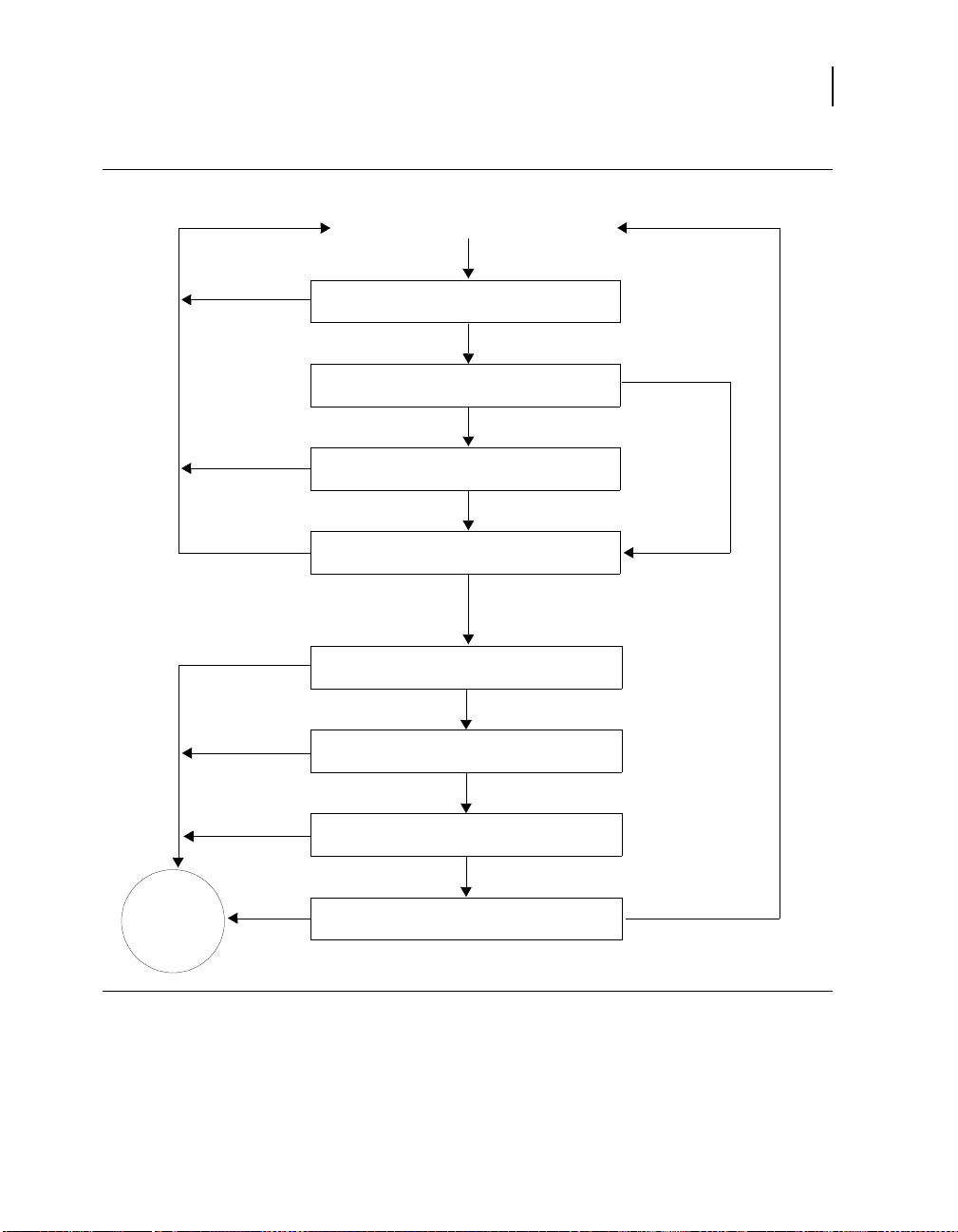
Detecting tachyarrhythmias
Figure 6-1. How detection features interact during initial detection
71
Detection overview
No
Ye s
No
No / suspended by
High Rate Timeout
Ye s
Update counts and pattern information
Has High Rate Timeout suspended detection
Does Stability reset the VT event count?
Are one or more PR Logic criteria on?
Is the median ventricular interval less than the SVT
Ventricular Event
Is the interval in the
VF, FVT, or VT detection zone?
Ye s
enhancements?
No
(VT and FVT via VT detection only)
No
Has a tachyarrhythmia event count
reached an NID?
Ye s
Ye s
Limit?
No
Ye s
Tachy
Episode
Detected
Ye s
No
Is there a double tachycardia in progress?
No
Are one or more PR Logic criteria withholding
detection?
Maximo DR 7278 Reference Manual
Ye s

72
Chapter 6
Detection overview
Suspending tachyarrhythmia detection
When detection is suspended, the device temporarily stops
classifying and counting tachyarrhythmia intervals. Sensing and
bradycardia pacing remain active, and the programmed detection
settings are not modified.
Detection is suspended
■
when the device senses the presence of a strong magnet. The
programmer head contains a magnet which suspends
detection, but once telemetry between the device and
programmer is established, detection resumes.
■
while performing any of the manual system tests, including
Underlying Rhythm, Pacing Threshold, Lead Impedance,
EGM Amplitude, and Charge/Dump. Detection automatically
resumes once the test is complete.
■
while performing a T-Shock, 50 Hz Burst, Manual Burst, or
PES Induction. You can choose to have the device
automatically resume detection after delivering the induction.
■
when you deliver a Manual or Emergency therapy. You can
resume detection by selecting the [Resume] button or
removing the programming head from the device.
■
when you select the on-screen [Suspend] button. You can
resume detection by selecting the [Resume] button or by
removing the programming head from the device.
■
during the automatic daily lead impedance measurements.
Detection resumes when the measurements are complete.
■
while the device is delivering an automatic tachyarrhythmia
therapy (including capacitor charging for defibrillation and
cardioversion). However, the device does continue to confirm
the detected episode during charging. Detection resumes
when the therapy is complete.
Note: The device suspends VT detection (and Combined
Count detection; see page 93) for 17 events following a
defibrillation therapy delivered in response to a detected VF.
■
during charging for Automatic Capacitor Formation. Detection
resumes when charging is complete.
1
1
If the defibrillation therapy is delivered as a result of a High Rate Timeout
Therapy operation, VT detection is not suspended (see page 114).
Maximo DR 7278 Reference Manual

Setting up sensing
The device provides bipolar sensing in both the atrium and
ventricle via the sensing electrodes of the implanted atrial and
ventricular leads. You can adjust the sensitivity to intracardiac
signals using independent atrial and ventricular sensitivity
settings. These settings define the minimum electrical amplitude
recognized by the device as an atrial or ventricular sensed event.
Proper sensing is essential for the safe and effective use of the
device. To provide appropriate sensing, the device uses:
■
auto-adjusting atrial and ventricular sensing thresholds
■
short (30 ms) cross-chamber blanking after paced events
■
no cross-chamber blanking after sensed events
See details about sensing on page 76.
Parameters
V. Sensitivity (mV) – Minimum amplitude of
electrical signal that registers as a sensed
ventricular event.
Detecting tachyarrhythmias
Setting up sensing
* Medtronic nominal setting
0.15, 0.3*, 0.45, 0.6,
0.9, 1.2
73
Considerations
A. Sensitivity (mV) – Minimum amplitude of
electrical signal that registers as a sensed
atrial event.
0.15, 0.3*, 0.45, 0.6,
0.9, 1.2, 1.5, 2.1
Review the following information before programming sensing
parameters.
Dual chamber sensing and bradycardia pacing modes – The
device senses in both the atrium and the ventricle at all times,
except when the programmed bradycardia pacing mode is DOO or
VOO. When the pacing mode is programmed to DOO or VOO
mode, there is no sensing in the ventricle. In order to program
either DOO or VOO mode, you must first disable detection.
Sensitivity thresholds – The programmed atrial and ventricular
sensitivity thresholds apply to all features related to sensing,
including detection and bradycardia pacing.
Maximo DR 7278 Reference Manual

74
Chapter 6
Setting up sensing
Bradycardia pacing and sensing – A combination of high
pacing pulse width or high amplitude with a low sensitivity
threshold may cause inappropriate sensing across chambers or in
the same chamber. Programming a lower pulse width, lower
amplitude, longer pace blanking, or a higher sensitivity threshold
may eliminate this inappropriate sensing.
Recommended ventricular sensitivity threshold – A ventr icular
sensitivity threshold of 0.3 mV is recommended to maximize the
probability of detecting VF and to limit the possibility of
oversensing and cross-chamber sensing.
High ventricular sensitivity threshold – Setting V. Sensitivity to
a value greater than 0.6 mV is not recommended except for
testing. Doing this may cause undersensing, which can cause any
of the following situations:
■
delayed or aborted cardioversion therapy
■
delayed defibrillation therapy (when VF confirmation is active)
■
asynchronous pacing
■
underdetection of tachyarrhythmias
Low ventricular sensitivity threshold – If you set V. Sensitivity
to its most sensitive value of 0.15 mV, the device will be more
susceptible to EMI, cross-chamber sensing, and oversensing.
Recommended atrial sensitivity threshold – An atrial
sensitivity threshold of 0.3 mV is recommended to optimize the
effectiveness of PR Logic detection criteria and atrial pacing
operations, while limiting the possibility of oversensing and
cross-chamber sensing.
High atrial sensitivity threshold – If you set the A. Sensitivity
value too high, the device may not provide reliable sensing of
P-waves during SVTs and sinus rhythm.
Low atrial sensitivity threshold – If you set the A. Sensitivity
value to its most sensitive value of 0.15 mV, the device will be more
susceptible to EMI, far-field R-wave sensing, and oversensing.
Maximo DR 7278 Reference Manual

Detecting tachyarrhythmias
Setting up sensing
Testing sensitivity after reprogramming – If you change the
ventricular sensitivity threshold, evaluate for proper sensing and
detection by inducing VF and allowing the device to automatically
detect and treat the arrhythmia.
Atrial pacing and ventricular sensing – If you program the
device to an atrial pacing mode, make sure that it does not sense
atrial pacing pulses as ventricular events.
Sensing during VF – Always verify that the device senses
properly during VF. If the device is not sensing or detecting
properly, program detection and therapies off, and evaluate the
system (making sure to monitor the patient for life-threatening
arrhythmias until you enable detection and therapies again). You
may need to reposition or replace the ventricular sensing lead to
achieve proper sensing.
Atrial lead selection – Atrial leads with minimal tip-to-ring
spacing may reduce far-field R-wave sensing.
Repositioning the atrial lead – You may need to reposition or
replace the atrial sensing lead if reprogramming the atrial
sensitivity threshold does not provide reliable atrial sensing during
SVTs and sinus rhythm.
75
How to program sensitivity
1. Select Params > Detection.
2. Select the desired A. Sensitivity
and V. Sensitivity parameters.
3. Select [PROGRAM].
2
3
1
Maximo DR 7278 Reference Manual
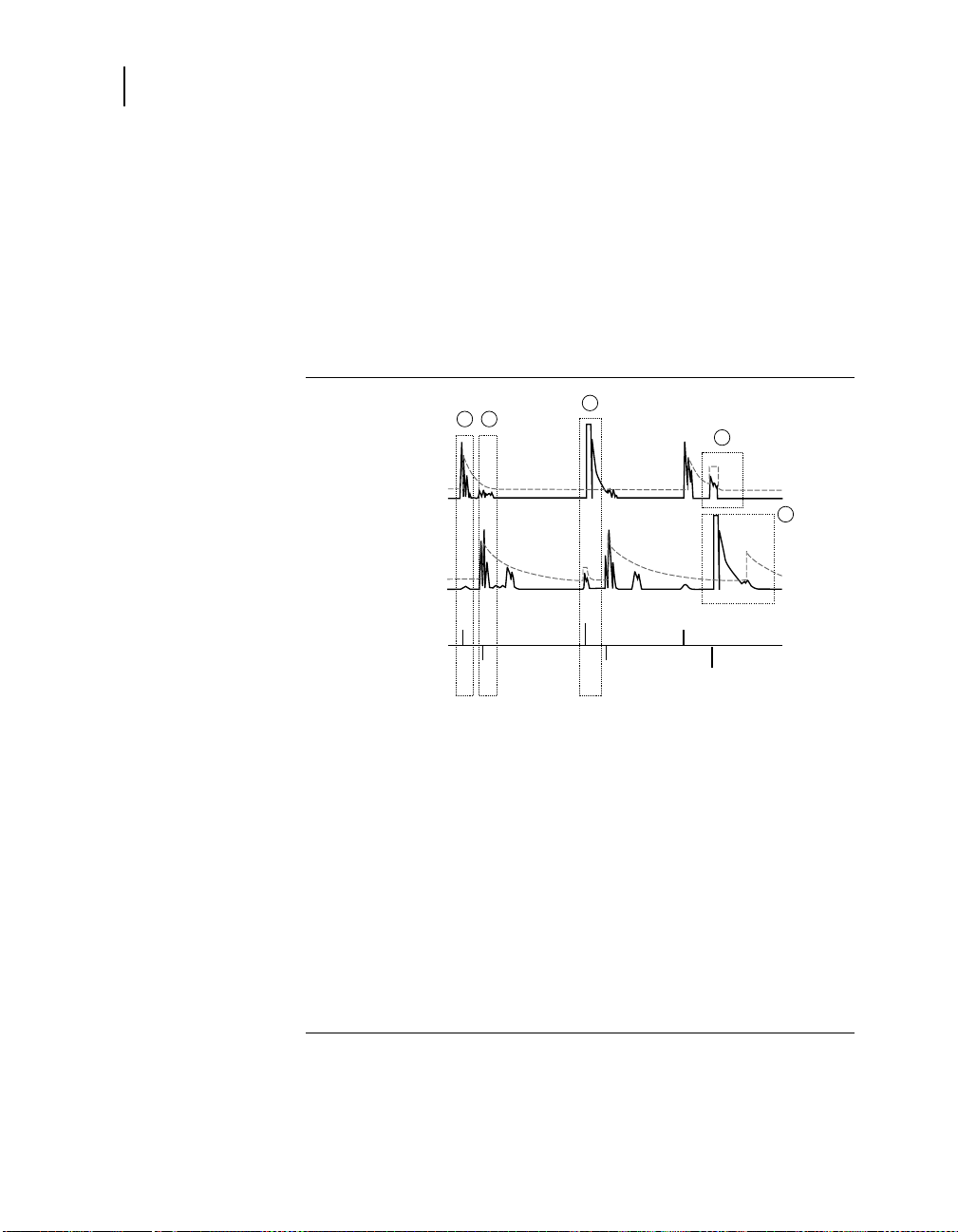
76
Chapter 6
Setting up sensing
Details about sensing
Auto-adjusting sensitivity thresholds
The device automatically adjusts the sensitivity thresholds after
certain paced and sensed events to help reduce oversensing from
T-waves, cross-chamber events, and pacing. Figure 6-2 shows
how sensitivity thresholds are adjusted after different types of
events.
Figure 6-2. Auto-adjusting sensitivity thresholds
A
S
Sensitivity
Threshold
4
V
P
5
74Autoadjust.eps
Rectified and
Filtered A. EGM
Rectified and
Filtered V. EGM
Marker Channel
1 2
A
S
3
A
P
V
S
V
S
1 After an atrial sensed event, the atrial sensitivity threshold
increases to 75% of the EGM peak (maximum: 8x the programmed
value, decay constant: 200 ms).
2 After a ventricular sensed event, the ventricular sensitivity threshold
increases to 75% of the EGM peak (maximum: 8x the programmed
value, decay constant: 450 ms).
3 After an atrial paced event, the device does not adjust the atrial
sensitivity threshold. The ventricular sensitivity threshold increases
by 0.45 mV (decay constant: 60 ms).
4 After a ventricular paced event, the atrial sensitivity threshold
increases to 4x the programmed value (maximum: 1.8 mV,
immediate return after 60 ms).
5 After the ventricular pace blanking period is finished, the ventricular
threshold increases to 4.5x the programmed value (maximum:
1.8 mV, decay constant: 450 ms).
a
The exponential decay continues through a subsequent ventricular pacing pulse
and its blanking period.
b
If the programmed sensitivity value exceeds 0.3 mV (ventricular) or 1.2 mV
(atrial), the threshold is not adjusted.
Maximo DR 7278 Reference Manual
a
b
b

Detecting tachyarrhythmias
Setting up sensing
Blanking periods
During a blanking period, the device does not sense electrical
signals. This helps prevent sensing of device pacing,
cardioversion and defibrillation pulses, post-pacing depolarization,
T-waves, and multiple sensing of the same event. The blanking
periods following paced events are longer than those following
sensed events to avoid sensing the atrial and ventricular
depolarizations.
Notes:
■
To enhance sensing and detection during tachyarrhythmias,
the device does not apply cross-chamber blanking (sense
blanking in the opposite chamber) after a sensed event.
■
Atrial sensing is still active during the Post-Ventricular Atrial
Blanking (PVAB) period (see “Post-Ventricular Atrial Blanking
Period” on page 170).
Table 6-1 shows the duration of the fixed blanking periods. For
information on programmable pace blanking periods, see
page 158.
Table 6-1. Fixed blanking periods
Cross-chamber blanking after atrial or ventricular pacing pulse 30 ms
77
Atrial blanking after sensed atrial event 100 ms
Ventricular blanking after sensed ventricular event 120 ms
Atrial and ventricular blanking after delivered
cardioversion or defibrillation therapy
Maximo DR 7278 Reference Manual
520 ms

78
Chapter 6
Detecting VF episodes
Detecting VF episodes
Refractory periods
During a refractory period, the device senses normally, but
classifies sensed events as refractory and limits its response to
these events. Pacing refractory periods prevent inappropriately
sensed signals, such as far-field R-waves (ventricular events
sensed in the atrium) or electrical noise, from triggering certain
pacing timing intervals.
Synchronization refractory periods help prevent the device from
delivering cardioversion and defibrillation therapies at
inappropriate times. See “Synchronizing defibrillation without
confirming VF” on page 125 and “Synchronizing cardioversion
after charging” on page 145.
Note: Refractory periods do not affect tachyarrhythmia detection.
The device detects VF episodes by examining the cardiac rhythm
for short ventricular intervals. If a predetermined number of
intervals occurs that are short enough to be considered VF events,
the device detects VF and delivers the first programmed VF
therapy. After therapy, the device continues to evaluate the
ventricular rhythm to determine if the episode is ongoing.
See details about VF detection on page 80.
Parameters
VF Detection Enable – Turns VF
detection on or off.
VF Interval (ms) – V-V intervals shorter
than this value are counted as VF events.
VF Initial NID – Number of Intervals to
Detect: number of VF events the device
must count to detect a VF episode.
VF Redetect NID – Number of Intervals
to Redetect: number of VF events the
device must count to redetect a
continuing VF after a therapy.
Maximo DR 7278 Reference Manual
* Medtronic nominal setting
On*, Off
240, 250, . . ., 320*, . . .,400
12/16, 18/24*, 24/32,
30/40, 45/60, 60/80,
75/100, 90/120,
105/140, 120/160
6/8, 9/12, 12/16*, 18/24,
21/28, 24/32, 27/36, 30/40

Considerations
Detecting tachyarrhythmias
Detecting VF episodes
Review the following information before programming
VF Detection parameters.
VF Interval minimum setting – To ensure proper VF detection,
you should not program the VF Interval less than 300 ms.
VF Interval maximum setting – Programming the VF Interval to
a value greater than 350 ms may cause inappropriate detection of
rapidly conducted atrial fibrillation as VF or FVT via VF. Intervals
shorter than the VF Interval are counted using the VF event
counter, which is more sensitive than the consecutive VT event
counter.
VF, FVT, and VT Intervals – To allow for normal variations in the
patient’s tachycardia interval, you should program the VF, FVT,
and VT intervals at least 40 ms apart.
Episode redetection – You can expedite redetection by
programming the VF and VT Redetect NIDs lower than the
Initial NIDs.
79
Enabling VF detection – When VF Detection Enable is
programmed On for the first time, the device
■
enables Automatic Capacitor Formation
■
starts recording Cardiac Compass data
■
starts recording lead performance trends (starting at
3:00 AM, by the device clock)
■
clears all brady pacing counters
VF detection and PR Logic criteria – You can program the
device to exclude rapidly conducted SVTs from VF Detection by
enabling the PR Logic detection criteria. Note that the SVT Limit
must be programmed shorter than the VF Interval in order for the
PR Logic criteria to affect VF detection. See “Enhancing detection
with PR Logic criteria” on page 98.
Double tachycardia detection – When any PR Logic detection
criteria are enabled, the device also enables double tachycardia
detection (VF, VT, or FVT in the presence of an SVT). See
“Detecting double tachycardias” on page 111.
Maximo DR 7278 Reference Manual
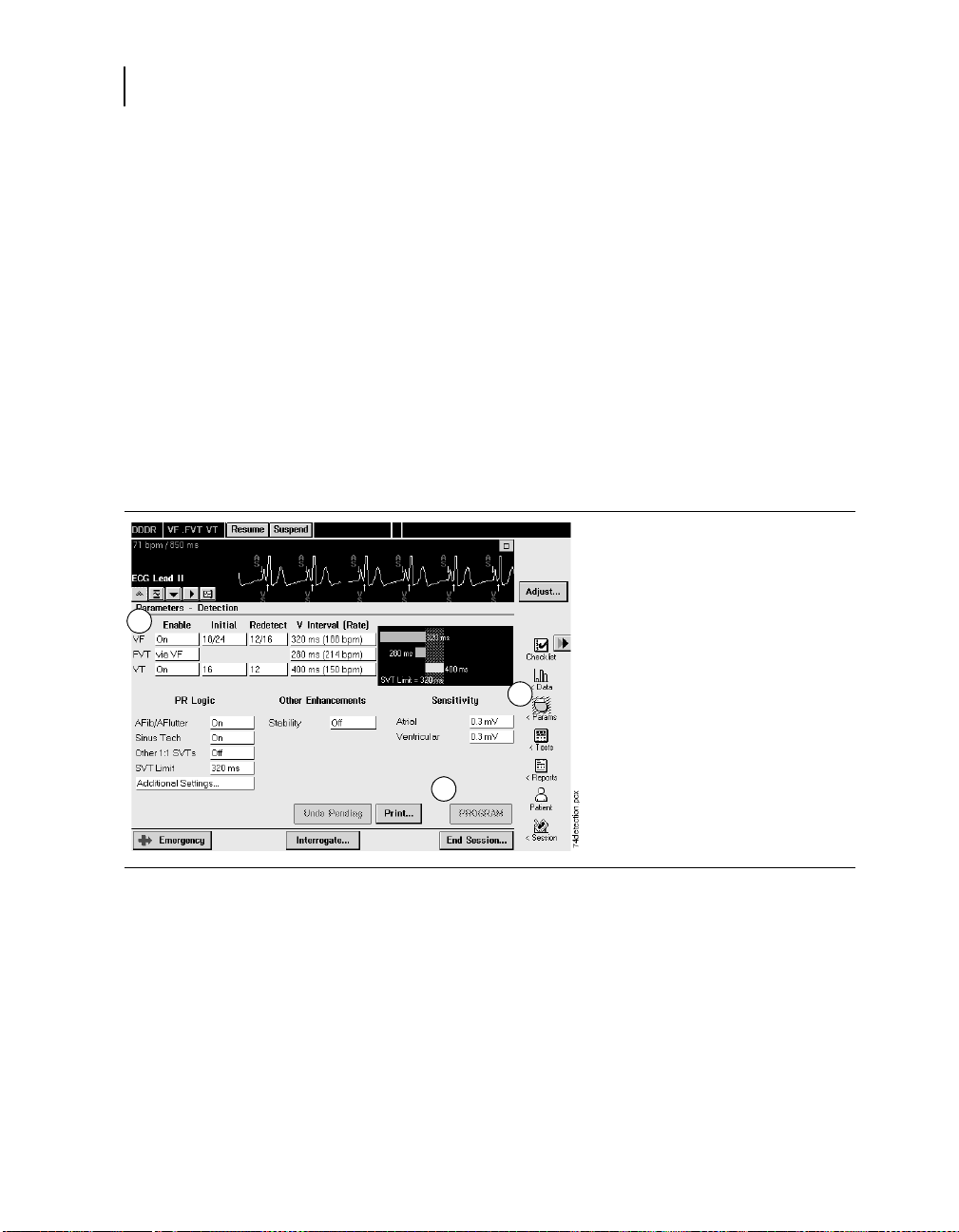
80
Chapter 6
Detecting VF episodes
Restrictions
How to program VF detection
2
Review the following information before programming
VF Detection parameters.
Tachyarrhythmia detection and bradycardia pacing – To e n s u r e
reliable ventricular tachyarrhythmia detection, the programmer
regulates the values available for bradycardia pacing and
tachyarrhythmia detection. See “Parameter interlocks” on
page 392.
VF detection backup – To ensure VF Detection backup during
VT and FVT episodes, if VF Detection is off, both VT Detection
and FVT Detection must also be off.
To program VF detection:
1. Select Params > Detection.
2. Select the desired values for
VF Enable, VF Initial NID,
VF Redetect NID, and
VF Interval.
3. Select [PROGRAM].
Details about VF detection
The device detects VF by counting the number of VF events, which
are V-V intervals shorter than the programmed VF Interval. On
each event, the device counts the number of recent VF events.
The number of recent events examined is called the VF detection
window. The size of the VF detection window is the second
number in the programmed VF NID (for example, 24 events if the
VF Initial NID is 18/24).
Maximo DR 7278 Reference Manual
1
3

The threshold for detecting VF is the first number in the
programmed VF NID (for example, 18 events if the VF Initial NID
is 18/24). This threshold is always 75% of the VF detection
window. That is, if 75% of the events in the VF detection window
are VF events, the device detects a VF episode (see Figure 6-3).
After the device detects VF, it delivers the first programmed VF
therapy. Following the therapy, if the number of VF events reaches
the programmed VF Redetect NID, the device redetects VF and
delivers the next programmed VF therapy.
Note: The device can also detect VF Episodes via the Combined
Count detection criterion (see page 93).
Figure 6-3. Device detects VF
ECG
Detecting tachyarrhythmias
Detecting VF episodes
1 2 3
81
A
S
A
S
A
R
A
R
A
R
A
R
A
R
Marker Channel
FSFSFSFSFSFSFSFSFSF
F
F
S
VSVSV
D
S
VF Event Count
V
S
VSV
FSFSF
S
1 2 3 4 5 6 6 7 8 9 10 11 12 13 1415 16 17 18
FSFSF
V
S
S
S
S
VF Interval
200 ms
1 VF starts, and the device begins counting VF events (intervals less than the programmed
VF Interval).
2 A ventricular interval occurs outside the VF detection zone. The VF event count is not
incremented.
3 The VF event count reaches the programmed VF NID value of 18 events out of 24, and the
device detects VF.
74VFDetection.eps
Maximo DR 7278 Reference Manual

82
Chapter 6
Detecting VT episodes
Detecting VT episodes
Parameters
The device detects VT episodes by examining the cardiac rhythm
for short ventricular intervals. If enough intervals occur that are
short enough to be considered VT events (but are not VF or FVT
events), the device detects VT and delivers the first programmed
VT therapy. After therapy, the device continues to evaluate the
ventricular rhythm to determine if the episode is ongoing.
You can program the device to detect and record VT episodes
without treating them with VT therapies by setting VT Detection
Enable to Monitor. If a patient’s VT episodes are well-tolerated,
this feature allows you to collect data about these episodes without
delivering therapy or affecting VF detection.
See details about VT detection on page 84.
* Medtronic nominal setting
VT Detection Enable – Turns VT
detection on or off, or enables VT
monitoring.
On, Off*, or Monitor
VT Interval (Rate) (ms) – V-V intervals
shorter than this value are counted as
VT events.
VT Initial NID – Number of Intervals to
Detect: number of VT events the device
must count to detect a VT episode.
VT Redetect NID – Number of Intervals
to Redetect: number of VT events the
device must count to redetect a
continuing VT after a therapy.
Considerations
Review the following information before programming
VT Detection parameters.
VF, FVT, and VT Intervals – To allow for normal variations in the
patient’s tachycardia interval, you should program the VF, FVT,
and VT intervals at least 40 ms apart.
Maximo DR 7278 Reference Manual
280, 290, . . ., 400*, . . ., 600
12, 16*, . . ., 52, 76, 100
4, 8, 12*, . . ., 52

Detecting tachyarrhythmias
Detecting VT episodes
Episode redetection – You can expedite redetection by
programming the VF and VT Redetect NIDs lower than the
Initial NIDs.
VT Detection Enable, AFib/AFlutter, and Sinus Tach – When
you set VT Detection Enable to On or Monitor, the AFib/AFlutter
and Sinus Tach parameters are also automatically set to On.
VT detection and Combined Count detection – When
VT Detection is On, the device applies the Combined Count
detection criterion to help speed detection of rhythms that
fluctuate between detection zones. Combined Count detection is
disabled if VT Detection is set to Off or Monitor. See “Detecting
tachyarrhythmia episodes with Combined Count” on page 93.
VT detection and rapidly conducted SVTs – You can program
the device to exclude rapidly conducted SVTs from VT detection
by enabling the PR Logic or Stability detection criteria. See
“Enhancing VT detection with the Stability criterion” on page 108,
and “Enhancing detection with PR Logic criteria” on page 98.
83
Restrictions
Double tachycardia detection – When any PR Logic detection
criteria are enabled, the device also enables double tachycardia
detection (VF, VT, or FVT in the presence of an SVT; see
page 111).
Review the following information before programming
VT detection parameters.
Tachyarrhythmia detection and bradycardia pacing – To e n s u r e
reliable ventricular tachyarrhythmia detection, the programmer
regulates the values available for bradycardia pacing and
tachyarrhythmia detection. See “Parameter interlocks” on
page 392.
VF detection backup – To ensure VF detection backup during
VT and FVT episodes, if VF Detection is off, both VT Detection
and FVT Detection must also be off.
Maximo DR 7278 Reference Manual
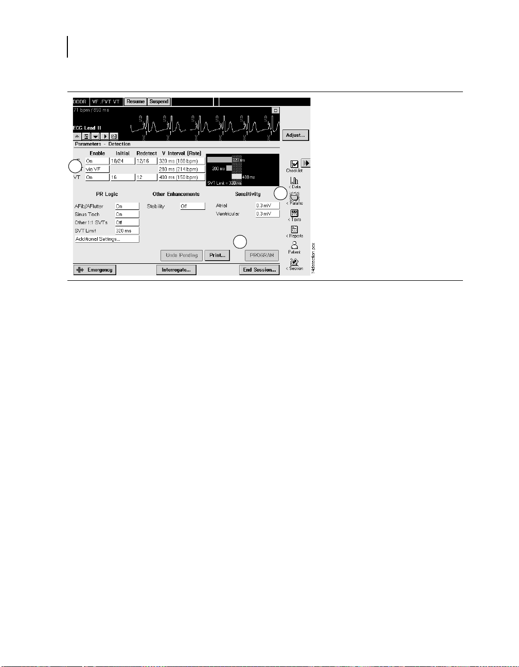
84
Chapter 6
Detecting VT episodes
How to program VT detection
2
Details about VT detection
To program VT detection:
1. Select Params > Detection.
2. Select the desired values for
VT Enable, VT Initial NID,
VT Redetect NID, and
VT Interval.
3. Select [PROGRAM].
1
3
The device detects VT by counting the number of consecutive VT
events. A VT event is a V-V interval shorter than the programmed
VT Interval but greater than or equal to the VF Interval. If the
number of consecutive VT events reaches the programmed VT
Initial NID, the device detects VT (see Figure 6-4).
The VT event count resets to zero whenever an interval occurs
that is greater than or equal to the programmed VT Interval. The
count remains at the current value if an interval is shorter than the
programmed VF Interval.
After the device detects VT, it delivers the first programmed VT
therapy. Following the therapy, if the VT event counter reaches the
VT Redetect NID, the device redetects VT and delivers the next
programmed therapy.
Note: The device can also detect VT Episodes via the Combined
Count detection criterion (see page 93).
Maximo DR 7278 Reference Manual

Figure 6-4. Device detects VT
ECG
132
Detecting tachyarrhythmias
Detecting VT episodes
85
A
S
A
S
ARARARARARARA
R
Marker Channel
VT Event Count
V
S
VSV
S
V
T
S
10123456
TSTSTSTSTST
S
S
VT Interval
ECG
ARARARARARARARARARARARA
R
Marker Channel
T
D
V
S
74VTDetection.eps
VT Event Count
TSTSTSTSTSTSTSTST
78910111213141516
S
VT Interval
200 ms
1 VT starts, and the device begins counting VT events (intervals less than the programmed
VT Interval, but greater than or equal to the VF Interval).
2 A ventricular interval occurs outside VT detection zone. The VT event count resets to zero.
3 The VT event count reaches the programmed VT NID of 16 events, and the device
detects VT.
Maximo DR 7278 Reference Manual

86
Chapter 6
Detecting VT episodes
VT monitoring
You can program the device to record VT episodes without
delivering VT therapy by setting VT Detection to Monitor. When VT
monitoring is enabled, the device detects VT episodes but does
not deliver VT therapy (see Figure 6-5). Instead, it records VT
episodes, labeling them as “monitored,” and waits for episode
termination to occur.
When VT Detection is set to Monitor, several detection operations
work differently.
VT event counting – Before the device detects an episode, it
counts VT events normally. However, once the VT Initial NID is
reached, the device sets the VT event count to zero and suspends
VT event counting for the rest of the episode.
VF and FVT detection – VF and FVT detection operate as if VT
detection is off. Specifically, Combined Count detection is
disabled, and FVT via VT detection is not selectable. If a
monitored VT episode accelerates into the FVT or VF detection
zone, the device applies the VF Initial NID to detect the new
tachyarrhythmia. Once an episode is in progress, VT event
counting doesn’t resume until the episode ends.
Caution: Programming the VF Interval greater than 350 ms
may result in inappropriate detection of rapidly conducted
atrial fibrillation as VF or FVT via VF. Intervals shorter than the
VF Interval are counted using the VF event counter, which is
more sensitive than the consecutive VT event counter.
PR Logic and Stability criteria – Before the device detects a
tachyarrhythmia episode, the PR Logic and Stability criteria, if
turned on, are applied. If a monitored VT episode accelerates into
the FVT or VF detection zone, the device continues to apply
PR Logic criteria as initial VF or FVT detection begins. However,
because the Stability feature does not affect VF detection or FVT
via VF detection, it is not applied.
Episode termination – The device compares ventricular
intervals to the VT Interval to identify when a VT monitored
episode has ended. However, if a VF episode or FVT via VF
episode occurs when VT monitoring is enabled, the device
compares ventricular intervals to the VF Interval to identify
episode termination.
Maximo DR 7278 Reference Manual

Figure 6-5. Device detects and monitors VT
ECG
Detecting tachyarrhythmias
Detecting VT episodes
2 31
87
A
S
A
ARARA
R
A
R
R
ARARARARA
A
R
R
Marker Channel
VT Event Count
V
S
VSTSTSTST
1234
TSTSTSTDTSTST
S
13 14 15 16 0 0 0
S
74VTmonitor.eps
VT Interval
200 ms
1 VT starts, and the device begins counting VT events (intervals less than the programmed
VT Interval but greater than or equal to the VF Interval).
2 The VT event count reaches the programmed VT NID of 16 events, and the device
detects VT.
3 After detecting the VT episode, the device resets the VT event count to zero and monitors
the episode until termination.
Maximo DR 7278 Reference Manual

88
Chapter 6
Detecting FVT episodes
Detecting FVT episodes
Parameters
The device detects episodes of Fast Ventricular Tachycardia (FVT)
by examining the cardiac rhythm for short ventricular intervals. If
enough intervals occur in the programmed FVT detection zone,
the device detects FVT and delivers the first programmed FVT
therapy. After therapy, the device continues to evaluate the
ventricular rhythm to determine if the episode is ongoing. To make
sure it delivers sufficiently aggressive therapies, the device can
merge the programmed detection zones during redetection to
increase sensitivity.
See details about FVT detection on page 90.
* Medtronic nominal setting
FVT Detection Enable – Enables FVT
detection via the VF or the VT
detection algorithm.
Off*, via VF, or via VT
Considerations
FVT Interval (Rate) (ms) – V-V
intervals between this value and the
programmed VF Interval are marked
as FVT events.
200, 210, . . ., 600
Review the following information before programming
FVT Detection parameters.
VF, FVT, and VT Intervals – To allow for normal variations in the
patient’s tachycardia interval, you should program the VF, FVT,
and VT intervals at least 40 ms apart.
Episode redetection – You can expedite redetection by
programming the VF and VT Redetect NIDs lower than the
Initial NIDs.
Maximo DR 7278 Reference Manual

Detecting tachyarrhythmias
Detecting FVT episodes
FVT detection enable – Your choice for an appropriate setting for
FVT Detection should depend on the patient’s VF and VT cycle
lengths. After determining a reliably sensitive VF Interval, consider
the following suggestions:
■
If the patient presents with a clinical VT interval in the VF
zone, select via VF to ensure reliable detection of VF. (VT
Detection need not be enabled at all.)
■
If the patient presents with two clinical VTs, both outside
the VF zone, select via VT to allow for correct classification
of the faster VT and to offer a separate therapy regimen for
each VT.
■
If the patient presents with only one clinical VT which is
outside the VF zone, select VF and VT Detection only, and
set FVT Enable to Off.
FVT detection and PR Logic criteria – You can program the
device to exclude rapidly conducted SVTs from FVT Detection by
enabling the PR Logic detection criteria. Note that the SVT Limit
must be programmed shorter than the VF Interval for the PR Logic
criteria to affect FVT via VF detection.
89
Restrictions
Double tachycardia detection – When any PR Logic detection
criteria is enabled, the device also enables double tachycardia
detection (VF, VT, or FVT in the presence of an SVT, see
page 111).
Review the following information before programming
FVT Detection parameters.
Tachyarrhythmia detection and bradycardia pacing – To
ensure reliable ventricular tachyarrhythmia detection, the
programmer regulates the values available for bradycardia pacing
and tachyarrhythmia detection. See “Parameter interlocks” on
page 392.
VF detection backup – To ensure VF Detection backup during
VT and FVT episodes, VT and FVT Detection cannot be on unless
VF Detection is also on.
Maximo DR 7278 Reference Manual

90
Chapter 6
Detecting FVT episodes
How to program FVT detection
2
FVT detection – To ensure reliable ventricular tachyarrhythmia
detection, the programmer regulates the values available for the
FVT parameter as follows:
■
VT Detection must be set to On if FVT Detection is set to
via VT.
■
If FVT Detection is set to via VF, the FVT Interval must be
programmed to a value shorter than the VF Interval.
■
If FVT Detection is set to via VT, the FVT Interval must be
programmed to a value greater than the VF Interval and less
than or equal to the VT Interval.
To program FVT detection:
1. Select Params > Detection.
2. Select the desired values for
FVT Enable and FVT Interval.
3. Select [PROGRAM].
Details about FVT detection
You can program the device to detect FVT episodes via the VF or
VT detection zone and NID.
When FVT Detection is set to via VF, a V-V interval within the FVT
detection zone is marked as an “FVT via VF” event. When the
VF NID is reached, the device reviews the last eight intervals:
■
If any of the last eight intervals are in the VF zone, it detects
the episode as VF.
■
If all of the last eight intervals are outside the VF zone, it
detects the episode as FVT (see Figure 6-6).
Maximo DR 7278 Reference Manual
1
3

When FVT Detection is set to via VT, a V-V interval within the FVT
detection zone is marked as an “FVT via VT” event. When the VT
NID is reached, the device reviews the last eight intervals:
■
If any of the last eight intervals are in the VF or FVT zones, it
detects the episode as FVT.
■
If all of the last eight intervals are outside the FVT and VF
zones, it detects the episode as VT.
Note: The device can also detect FVT episodes via the Combined
Count detection criterion (see page 93).
Figure 6-6. Device detects FVT via VF
Detecting tachyarrhythmias
Detecting FVT episodes
91
1 2
3
ECG
A
S
A
S
ARARA
A
R
ARARARARARARARARA
R
Marker Channel
VF Event Count
V
S
V
S
V
T
T
S
F
1 1 2345
TFTFTFT
S
TFT
F
TFTFTFTFTFV
F
13 14 15 16 17 18
VF and FVT Intervals
1 A fast ventricular tachycardia starts, and the first event falls into the FVT detection zone.
2 The second event of the FVT episode has an interval that falls into the VT zone. The VF
event count is not incremented.
3 The device detects FVT after the VF event count reaches the VF Initial NID.
R
S
74FvtDetect.eps
200 ms
Maximo DR 7278 Reference Manual
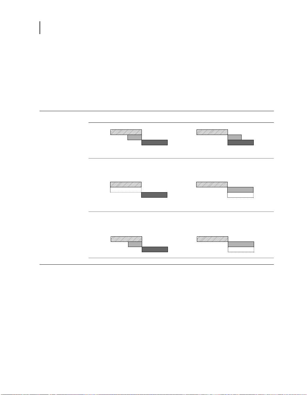
92
Chapter 6
Detecting FVT episodes
Figure 6-7. FVT zone merging
Zone merging after detection
To ensure the device delivers sufficiently aggressive therapies
during an extended or highly variable tachyarrhythmia episode,
the device merges detection zones during redetection in some
instances, as shown in Figure 6-7. The merged zone configuration
uses the event counting and therapies for the faster arrhythmia
and remains in effect until episode termination.
FVT set to “via VF” FVT set to “via VT”
Before
detection:
After VF
detection:
After FVT
detection:
VF
FVT
VT
VF and FVT zones merge, leaving
a larger VF zone.
VF
FVT
VT
VF
FVT
VT
VT and FVT zones merge, leaving a
larger FVT zone.
VF
FVT
VT
All zones remain unchanged. VT and FVT zones merge, leaving a
larger FVT zone.
VF
FVT
VT
Detection Intervals: VF Interval: 320 ms, FVT Interval: 280 ms / 360 ms , VT Interval: 400 ms
VF
FVT
VT
FVT1.eps
FVT2.eps
FVT3.eps
Maximo DR 7278 Reference Manual

Detecting tachyarrhythmias
Detecting tachyarrhythmia episodes with Combined Count
Detecting tachyarrhythmia episodes with Combined Count
Because the device counts VF and VT events separately, rhythms
with variable cycle lengths can cause both event counts to
increment during an episode. To prevent these rhythms from
delaying detection, the device automatically enables the
Combined Count detection criterion if both VF and VT detection
are programmed On.
The Combined Count criterion compares the sum of the VF and
VT event counts to the Combined Number of Intervals to Detect
(CNID), which the device calculates automatically from the
programmed VF NID values. If the CNID is met, the device reviews
the recent intervals to determine if the episode should be treated
as a VF, FVT, or VT episode. The Combined Count criterion
applies during both initial detection and redetection.
Details about Combined Count detection
The Combined Count detection algorithm expedites detection or
redetection of ventricular tachyarrhythmias with ventricular
intervals that fluctuate between the VF and VT detection zones.
When VT detection is on, the device applies Combined Count
detection, which tracks the combined number of VT and VF events
counted. If this sum reaches the Combined Number of Intervals to
Detect (CNID), the device detects VF, FVT, or VT. Combined
Count detection also applies to redetected episodes.
93
Note: Combined Count detection is off when VT detection is set to
Monitor or Off.
If the VF event counter reaches six, the device automatically
applies the Combined Number of Intervals to Detect (CNID). The
CNID is calculated by multiplying the current VF NID (Initial or
Redetect) by 7/6 and rounding down. Table 6-2 shows the CNID
values that correspond to each VF NID value.
Table 6-2. CNID values for each initial or redetect VF NID value
VF NID CNID VF NID CNID
6/8 7 21/28 24
9/12 10 24/32 28
12/16 14 27/36 31
18/24 21 30/40 35
Maximo DR 7278 Reference Manual

94
Chapter 6
Detecting tachyarrhythmia episodes with Combined Count
Combined Count detection is fulfilled when the sum of the VF and
VT event counts equals or exceeds the CNID. The device then
reviews the last eight intervals and classifies the episode as
■
VF, if any of the last eight were in the VF zone.
■
FVT, if FVT Detection is enabled and none of the last eight was
in the VF zone, but one or more was in the FVT zone.
■
VT, if all eight were outside the VF zone (and FVT zone, if FVT
detection is enabled).
Figure 6-8. Device detects VF with the Combined Count criterion
1
2
3
ECG
A
ARARARARARARARARARARARA
S
ARARARARARARA
R
R
A
R
R
A
Marker Channel
V
VSF
VF Event Count
VT Event Count
Combined Count
F
S
S
1 2 3 4 5 6 7 8 9 10 11 12 13 14 15 16 17
1 2 3 4
1 2 3 4 5 6 7 8 9 10 11 12 13 14 15 16 17 18 19 20 21
FSFSFSFSF
S
FST
S
SFSFSFSFSFSFSFSFS
TST
F
FDV
S
S
S
VF and VT Interval
200 ms
1 A slow VF episode starts, with a ventricular cycle length that varies between the VF and VT
detection zones.
2 When a VT event occurs, the device increments the VT event count and the Combined
Count.
3 The device detects VF even though the VF event count hasn’t yet reached the VF Initial NID
(18/24 in this example). The Combined Count reaches the CNID value of 21 first.
74Combined.eps
Maximo DR 7278 Reference Manual

Detecting tachyarrhythmias
Monitoring episodes for termination or redetection
Monitoring episodes for termination or redetection
Once the device detects an arrhythmia, it considers the episode
ongoing until it detects that the episode has ended. After delivering
therapy, it monitors the ventricular rhythm using the programmed
Redetect NIDs. If one of these NIDs is met, the device delivers the
next programmed therapy for the detected arrhythmia.
See details about episode termination and redetection on
page 96.
Parameters
* Medtronic nominal setting
VF Redetect NID – Number of
Intervals to Redetect: number of VF
events the device must count to
redetect a continuing VF after a
therapy.
6/8, 9/12, 12/16*, 18/24,
21/28, 24/32, 27/36, 30/40
95
Considerations
VT Redetect NID – Number of
Intervals to Redetect: number of VT
events the device must count to
redetect a continuing VT after a
therapy.
4, 8, 12*, . . . 52
Review the following information before programming redetection
parameters.
Initial and Redetect NIDs – You can expedite redetection by
programming the VF and VT Redetect NIDs lower than the
Initial NIDs.
Maximo DR 7278 Reference Manual

96
Chapter 6
Monitoring episodes for termination or redetection
How to program redetection parameters
2
3
Details about episode termination and redetection
After a therapy is delivered, the device evaluates the ventricular
rhythm to determine if the episode has terminated, is continuing,
or has changed to a different arrhythmia.
1. Select Params > Detection.
2. Select the desired values for
VT Redetect NID and
VF Redetect NID.
3. Select [PROGRAM].
1
Episode termination
The device determines that the episode has terminated if one of
the following conditions occurs:
■
eight consecutive ventricular intervals are greater than or
equal to the programmed VT interval.
■
20 seconds elapse with no ventricular intervals shorter than
the programmed VT interval.
After antitachycardia pacing therapy, the device begins evaluating
intervals for episode termination on the first ventricular cycle. After
cardioversion or defibrillation, the device begins evaluating
intervals for episode termination on the second ventricular event.
(Due to the extended post shock blanking, this event may be the
third event on the electrogram.)
Note: Any subsequent detection after the end of the episode
marks the start of a new episode.
1
VF interval if VT Detection is set to Off or Monitor, and the episode is a VF or an
FVT via VF episode.
Maximo DR 7278 Reference Manual
1
1

Monitoring episodes for termination or redetection
Episode redetection
After the device detects a tachyarrhythmia episode and delivers a
therapy, the device redetects an arrhythmia if the VF or VT event
count reaches the Redetect NID or if the combined VF and VT
event count reaches the Redetect CNID (see “Detecting
tachyarrhythmia episodes with Combined Count” on page 93).
The device then delivers the next programmed therapy for the
current arrhythmia and resumes monitoring for the outcome of that
therapy. Figure 6-9 shows an example of redetection.
Figure 6-9. VT episode redetected after therapy
ECG
Detecting tachyarrhythmias
97
2 31
ARASASASASASARARARARARARARARARARARARA
Marker Channel
VT Event Count
VT Interval
T
TPT
P
D
TPT
TPTPTPTPTPTSTSTSTSTSTSTSTSTSTSTST
P
016 0 1 2 3 4 5 6 7 8 9 10 11 12
1 A VT episode is detected, and the device delivers a Burst ATP therapy.
2 After therapy, the device continues to detect events in the VT zone.
3 When the VT event count reaches the VT Redetect NID, the device redetects the VT.
Notes:
■
The device suspends VT detection (and Combined Count
detection) for 17 events following a defibrillation therapy
delivered in response to a detected VF.
1
Suspending VT
detection helps avoid detecting transient VTs that can follow
high voltage therapies.
■
The PR Logic criteria are not applied during redetection.
However, the Stability criterion may withhold detection or
redetection of VT throughout an episode.
1
If the defibrillation therapy is delivered as a result of a High Rate Timeout
Therapy operation, VT detection is not suspended (see page 114).
R
D
74Redetect.eps
200 ms
Maximo DR 7278 Reference Manual

98
Chapter 6
Enhancing detection with PR Logic criteria
VT acceleration
If the device redetects VT, it classifies the rhythm as accelerated if
the average of the four intervals before redetection is at least
60 ms less than the average of the four intervals before initial VT
detection. The most recent interval average is used to identify VT
acceleration if VT is redetected again during the episode.
If the device redetects VF or an accelerated VT after an
antitachycardia pacing sequence delivery, it skips the subsequent
pacing therapy sequences for the duration of the episode and
delivers the next therapy programmed for the current arrhythmia.
Enhancing detection with PR Logic criteria
The PR Logic detection criteria are designed to withhold
inappropriate ventricular detection during episodes of rapidly
conducted supraventricular tachycardia (SVT). The device
analyzes the activation patterns and timing in both chambers
using PR Logic pattern and rate analysis. This information helps
identify evidence of atrial fibrillation, atrial flutter, sinus
tachycardia, and other 1:1 SVTs. If this analysis indicates the
presence of one or more of these rhythms, the device withholds
detection.
For more information, see
■
“Details about PR Logic pattern and rate analysis” on
page 102
■
“Details about the PR Logic detection criteria” on page 106
Parameters
Maximo DR 7278 Reference Manual
t
AFib/AFlutter – Identifies rapidly conducted
atrial fibrillation, atrial flutter, or atrial tachycardia.
Sinus Tach – Identifies sinus tachycardia. On
1:1 VT-ST Boundary (%) – Threshold between
the retrograde and antegrade zones used by A-V
pattern analysis. Allows customizing of the
Sinus Tach criterion for patients with slow
one-to-one conduction.
* Medtronic nominal setting
Ona, Off*
a
, Off*
35, 50*, 66, 75, 85

Detecting tachyarrhythmias
Enhancing detection with PR Logic criteria
* Medtronic nominal setting
99
Considerations
Other 1:1 SVTs – Identifies other one-to-one
SVTs where the atrial and ventricular activation
are roughly simultaneous.
SVT Limit (ms) – Defines the minimum
ventricular interval at which the device applies
the PR Logic criteria.
a
When you set VT Detection Enable to On or Monitor, the AFib/AFlutter and
Sinus Tach parameters are also automatically set to On.
On, Off*
240, 250, . . ., 320*,
330, 340, . . ., 600
Review the following information before programming PR Logic
parameters.
Cautions:
■
Before enabling the Other 1:1 SVTs criterion, ensure that
the atrial lead has matured. This criterion could
inappropriately withhold therapy if atrial sensing is
compromised by an unstable or dislodged atrial lead.
■
Use caution when programming the Other 1:1 SVTs
criterion in patients who exhibit slow 1:1 retrograde
conduction during VF or VT. This criterion could
inappropriately withhold VF/VT therapy in such patients.
See “Pattern analysis of A-V and V-A intervals” on
page 102.
■
Use caution when programming the 1:1 VT-ST Boundary.
Incorrect programming of this parameter can result in
inappropriate therapies or underdetection of
tachyarrhythmias.
PR Logic criteria and double tachycardia detection – When
any of the PR Logic criteria are enabled, the device also enables
double tachycardia detection (VF, VT, or FVT in the presence of an
SVT; see page 111).
Sinus Tach and 1:1 VT-ST Boundary – When enabling the
Sinus Tach criterion in patients who exhibit slow 1:1 retrograde
conduction during VF or VT or slow antegrade conduction during
SVTs, make sure to set the 1:1 VT-ST Boundary parameter
appropriately. See “Customizing PR Logic for patients with slow
conduction” on page 100.
Maximo DR 7278 Reference Manual

100
Chapter 6
Enhancing detection with PR Logic criteria
VT Detection Enable, AFib/AFlutter and Sinus Tach – When
you set VT Detection Enable to On or Monitor, the AFib/AFlutter
and Sinus Tach parameters also automatically set to On.
SVT Limit – To ensure that therapy is delivered for
hemodynamically compromising rates of any origin, the device
always delivers therapy when the median ventricular interval is
less than the programmed SVT Limit (nominally 320 ms) if VT, VF,
or FVT detection criteria are satisfied.
VF Interval and SVT Limit – If you program an SVT Limit greater
than the VF Interval, you are effectively disabling the PR Logic
criteria for VF detection.
Customizing PR Logic for patients with slow conduction
Slow antegrade conduction during an SVT or slow 1:1 retrograde
conduction during VT can adversely affect the accuracy of the
Sinus Tach and Other 1:1 SVTs criteria. The 1:1 VT-ST Boundary
parameter allows you to customize the Sinus Tach criterion for
patients who exhibit slow conduction.
Note: Changing the 1:1 VT-ST Boundary parameter does not
affect the operation of the Other 1:1 SVTs criterion. Use caution
when enabling this criterion in patients who exhibit slow antegrade
or retrograde conduction.
The 1:1 VT-ST Boundary parameter represents an A-V interval
that is a percentage of a V-V interval. This value separates the
retrograde and antegrade zones used by PR Logic pattern
analysis operations. See “Pattern analysis of A-V and V-A
intervals” on page 102.
If slow retrograde or antegrade conduction causes events to occur
in the incorrect zone, you can use the 1:1 VT-ST Boundary
parameter to increase the size of the appropriate zone. See
Figure 6-10 on page 103.
If a patient exhibits slow antegrade or retrograde conduction and
could benefit from a different 1:1 VT-ST Boundary setting, choose
a new setting as follows:
■
If the patient exhibits long V-A intervals during VT with 1:1
retrograde conduction, select 35%.
Maximo DR 7278 Reference Manual
 Loading...