

Page 1

1
/C/TEMP/197120001B_view-1.pdf
Pacemaker
Information and
Programming
Guide
9959E Software
Use to program the
following pacemakers:
PREVA™D 7068
PREVA™ST DR 7078
PREVA™DR 7088, 7089
PREVA™SR 8088, 8089
Page 2

Page 3

Medtronic
¨
Pacemaker Information and
Programming Guide for Models
7068, 7078, 7088/89 and 8088/89
A Guide to Understanding Pacemakers
and Using the 9790 Programmers
© Medtronic, Inc. 1997
All Rights Reserved
Printed In USA
Page 4

Page 5

How To Use This Guide
This Pacemaker Information and Programming Guide and the product
information manual packaged with each pacemaker form a two manual set
covering information about the pacing system. This guide provides
comprehensive information about the Model 7068, 7078, 7088/89, and
8088/89 pacemakers, the pacing lead system, and the Medtronic®9790
programmer.*
Organization of this guide divides information about the pacing system
into three major parts as follows:
Part I — This part describes the programmer capabilities. It provides
instructions on how to set up the programmer and apply its functions for
programming applicable pacemaker features and retrieving data.
Part II — This part describes all pacemaker parameters and features,
including pacing modes, rate response options, special therapy options,
diagnostic reporting features, and information for troubleshooting the
pacing system. It supplements the product information manual, which gives
information needed primarily at pacemaker implantation. In this part, the
clinical intent of model-specific features is described, as well as
illustrations of operation and programming considerations useful in the
follow-up setting.
NOTE: Part II provides all possible pacing and programming features for
the pacemaker family without any specific reference to the models. Refer
to Part III to determine which features apply to specific pacemaker models.
Part III — This part includes quick-reference information organized by
topic or feature. To find information on a specific pacemaker model, look
under each topic. Of particular help are “Modes and Parameters” and
“Diagnostics,” which identify which features (presented in Part II) are
applicable to each pacemaker model.
* CapSure, Marker Channel, Medtronic, and Teletrace are all trademarks of Medtronic, Inc.
Lead information provided in this guide describes pacemaker/lead compatibility. Details
about the leads are covered in the applicable lead technical manual.
iii
Page 6

Page 7

Table of Contents
Part I Using the Programmer
Chapter 1 - Using the Programmer with the Pacemaker Models 1-1
When to Use Part I of this Manual . . . . . . . . . . . . . . . . . . . . . . . . . . 1-2
Conventions Used in Part I of this Manual. . . . . . . . . . . . . . . . . . . . . . 1-3
General Warnings and Precautions. . . . . . . . . . . . . . . . . . . . . . . . . . 1-4
Display Screen Format and Interactive Features . . . . . . . . . . . . . . . . . . . 1-5
A Guide to Using the Menu and Command Buttons. . . . . . . . . . . . . . . . . 1-8
Chapter 2 - Procedures to Know Before You Begin 2-1
Using the Programming Head . . . . . . . . . . . . . . . . . . . . . . . . . . . . 2-2
Programming Emergency Parameters . . . . . . . . . . . . . . . . . . . . . . . . 2-5
Interrogating the Pacemaker . . . . . . . . . . . . . . . . . . . . . . . . . . . . . 2-6
Canceling the Programming Head Magnet. . . . . . . . . . . . . . . . . . . . . . 2-8
Printing Reports During a Patient Session . . . . . . . . . . . . . . . . . . . . . . 2-9
Printing Reports After a Session Has Ended . . . . . . . . . . . . . . . . . . . . 2-12
Transferring Session Data to a Diskette . . . . . . . . . . . . . . . . . . . . . . 2-12
Using the HELP Options . . . . . . . . . . . . . . . . . . . . . . . . . . . . . . 2-15
Chapter 3 - Starting and Ending a Patient Session 3-1
Before You Begin . . . . . . . . . . . . . . . . . . . . . . . . . . . . . . . . . . 3-2
Turning the Programmer ON. . . . . . . . . . . . . . . . . . . . . . . . . . . . . 3-3
Selecting the Pacemaker Model . . . . . . . . . . . . . . . . . . . . . . . . . . . 3-4
Selecting the Desired Function. . . . . . . . . . . . . . . . . . . . . . . . . . . . 3-7
Ending a Patient Session . . . . . . . . . . . . . . . . . . . . . . . . . . . . . . . 3-9
Chapter 4 - Retrieving Pacing System Data 4-1
Displaying Present Parameter Settings. . . . . . . . . . . . . . . . . . . . . . . . 4-2
Displaying a Summary of Pacemaker Status. . . . . . . . . . . . . . . . . . . . . 4-5
Displaying Battery and Lead Information . . . . . . . . . . . . . . . . . . . . . . 4-9
Displaying a Graph of Recorded Diagnostic Data . . . . . . . . . . . . . . . . . 4-11
Chapter 5 - Displaying and Printing the PatientÕs ECG and EGM 5-1
Printing the Patient’s ECG and EGM . . . . . . . . . . . . . . . . . . . . . . . . 5-2
Displaying the Patient’s ECG and EGM. . . . . . . . . . . . . . . . . . . . . . . 5-5
v
Page 8

Freezing the ECG Trace . . . . . . . . . . . . . . . . . . . . . . . . . . . . . . 5-10
Displaying a Marker Channel™ Diagram . . . . . . . . . . . . . . . . . . . . . 5-14
Chapter 6 - Programming Pacing Parameters 6-1
Programming Pacing Parameters. . . . . . . . . . . . . . . . . . . . . . . . . . . 6-2
Programming Additional Parameters . . . . . . . . . . . . . . . . . . . . . . . . 6-7
Chapter 7 - Determining and Evaluating Parameter Settings 7-1
Measuring Stimulation Thresholds. . . . . . . . . . . . . . . . . . . . . . . . . . 7-2
Programming Temporary Parameter Values . . . . . . . . . . . . . . . . . . . . 7-10
Measuring Rate and AV Interval . . . . . . . . . . . . . . . . . . . . . . . . . . 7-13
Chapter 8 - Collecting and Retrieving Diagnostic Data 8-1
About the Diagnostics Function . . . . . . . . . . . . . . . . . . . . . . . . . . . 8-2
Types of Data You Can Record . . . . . . . . . . . . . . . . . . . . . . . . . . . 8-3
Programmable Parameter Options . . . . . . . . . . . . . . . . . . . . . . . . . . 8-7
About the Setup Options . . . . . . . . . . . . . . . . . . . . . . . . . . . . . . . 8-8
Programming the Pacemaker to Record Data . . . . . . . . . . . . . . . . . . . . 8-9
Displaying a Graph of the Recorded Data . . . . . . . . . . . . . . . . . . . . . 8-13
Printing the Diagnostic Data . . . . . . . . . . . . . . . . . . . . . . . . . . . . 8-15
Clearing Recorded Data From the Pacemaker . . . . . . . . . . . . . . . . . . . 8-16
Chapter 9 - Programmer Setup Options 9-1
Setting the Time and Date . . . . . . . . . . . . . . . . . . . . . . . . . . . . . . 9-2
Connecting an External Recorder or Monitor . . . . . . . . . . . . . . . . . . . . 9-3
Using the CALIBRATE Option . . . . . . . . . . . . . . . . . . . . . . . . . . . 9-4
Setting Up Site Nominal Parameter Values . . . . . . . . . . . . . . . . . . . . . 9-6
Setting the Artifact Display . . . . . . . . . . . . . . . . . . . . . . . . . . . . . 9-10
Part II Understanding Pacemaker Operation
Chapter 10 - Pacing Modes 10-1
Introduction . . . . . . . . . . . . . . . . . . . . . . . . . . . . . . . . . . . . . 10-3
Mode Selection Decision Tree . . . . . . . . . . . . . . . . . . . . . . . . . . . 10-5
Mode Pertinency Tables . . . . . . . . . . . . . . . . . . . . . . . . . . . . . . 10-6
DDDR Mode . . . . . . . . . . . . . . . . . . . . . . . . . . . . . . . . . . . . 10-8
DDD Mode . . . . . . . . . . . . . . . . . . . . . . . . . . . . . . . . . . . . 10-10
DDIR Mode . . . . . . . . . . . . . . . . . . . . . . . . . . . . . . . . . . . . 10-12
DDI Mode . . . . . . . . . . . . . . . . . . . . . . . . . . . . . . . . . . . . . 10-14
vi
Page 9

DVIR Mode . . . . . . . . . . . . . . . . . . . . . . . . . . . . . . . . . . . . 10-16
DVI Mode . . . . . . . . . . . . . . . . . . . . . . . . . . . . . . . . . . . . . 10-18
VDD Mode . . . . . . . . . . . . . . . . . . . . . . . . . . . . . . . . . . . . 10-20
AAIR Mode . . . . . . . . . . . . . . . . . . . . . . . . . . . . . . . . . . . . 10-22
AAI Mode . . . . . . . . . . . . . . . . . . . . . . . . . . . . . . . . . . . . . 10-24
VVIR Mode . . . . . . . . . . . . . . . . . . . . . . . . . . . . . . . . . . . . 10-26
VVI Mode . . . . . . . . . . . . . . . . . . . . . . . . . . . . . . . . . . . . . 10-28
AAT/VVT Modes . . . . . . . . . . . . . . . . . . . . . . . . . . . . . . . . . 10-30
DOOR/AOOR/VOOR Modes . . . . . . . . . . . . . . . . . . . . . . . . . . . 10-32
DOO/AOO/VOO Modes . . . . . . . . . . . . . . . . . . . . . . . . . . . . . 10-34
ODO/ OAO/ OVO Modes . . . . . . . . . . . . . . . . . . . . . . . . . . . . . 10-36
Chapter 11 - Rate Response Therapy Options 11-1
Rate Responsive Pacing. . . . . . . . . . . . . . . . . . . . . . . . . . . . . . . 11-2
Activity Threshold . . . . . . . . . . . . . . . . . . . . . . . . . . . . . . . . . 11-4
Activity Rate Response . . . . . . . . . . . . . . . . . . . . . . . . . . . . . . . 11-6
Acceleration and Deceleration Times. . . . . . . . . . . . . . . . . . . . . . . . 11-8
Chapter 12 - Pacemaker Timing 12-1
Rates . . . . . . . . . . . . . . . . . . . . . . . . . . . . . . . . . . . . . . . . 12-2
AV Intervals. . . . . . . . . . . . . . . . . . . . . . . . . . . . . . . . . . . . . 12-8
Blanking Periods. . . . . . . . . . . . . . . . . . . . . . . . . . . . . . . . . . 12-14
Refractory Periods . . . . . . . . . . . . . . . . . . . . . . . . . . . . . . . . . 12-16
High Rate Atrial Tracking . . . . . . . . . . . . . . . . . . . . . . . . . . . . . 12-23
Chapter 13 - Lead/Cardiac Tissue Interface 13-1
Selecting Pacing Parameters . . . . . . . . . . . . . . . . . . . . . . . . . . . . 13-2
Selecting Sensing Parameters. . . . . . . . . . . . . . . . . . . . . . . . . . . . 13-5
Transtelephonic Capture Verification with TMT . . . . . . . . . . . . . . . . . . 13-8
Chapter 14 - Special Therapy Options 14-1
Mode Switch . . . . . . . . . . . . . . . . . . . . . . . . . . . . . . . . . . . . 14-2
Non-Competitive Atrial Pacing . . . . . . . . . . . . . . . . . . . . . . . . . . . 14-5
PMT Intervention . . . . . . . . . . . . . . . . . . . . . . . . . . . . . . . . . . 14-7
Ventricular Safety Pacing. . . . . . . . . . . . . . . . . . . . . . . . . . . . . . 14-9
Single Chamber Hysteresis . . . . . . . . . . . . . . . . . . . . . . . . . . . . 14-11
Chapter 15 - Telemetry Data 15-1
Parameter Summary. . . . . . . . . . . . . . . . . . . . . . . . . . . . . . . . . 15-2
Battery and Lead Information. . . . . . . . . . . . . . . . . . . . . . . . . . . . 15-4
Marker Channel™ Telemetry. . . . . . . . . . . . . . . . . . . . . . . . . . . . 15-6
vii
Page 10

Intracardiac Electrogram (EGM) . . . . . . . . . . . . . . . . . . . . . . . . . . 15-8
Extended Telemetry . . . . . . . . . . . . . . . . . . . . . . . . . . . . . . . . 15-10
Chapter 16 - Miscellaneous Operations 16-1
Magnet Mode Operation . . . . . . . . . . . . . . . . . . . . . . . . . . . . . . 16-2
Temporary Programming . . . . . . . . . . . . . . . . . . . . . . . . . . . . . . 16-5
Electrical Reset . . . . . . . . . . . . . . . . . . . . . . . . . . . . . . . . . . . 16-6
Elective Replacement Indicator (ERI) . . . . . . . . . . . . . . . . . . . . . . . 16-8
Emergency Pacing . . . . . . . . . . . . . . . . . . . . . . . . . . . . . . . . . 16-9
Chapter 17 - Diagnostics 17-1
Introduction to Diagnostics . . . . . . . . . . . . . . . . . . . . . . . . . . . . . 17-2
Event Summary . . . . . . . . . . . . . . . . . . . . . . . . . . . . . . . . . . . 17-4
Rate Histogram . . . . . . . . . . . . . . . . . . . . . . . . . . . . . . . . . . . 17-6
Rate Versus Time Trend . . . . . . . . . . . . . . . . . . . . . . . . . . . . . . 17-8
Chapter 18 - Troubleshooting the Pacing System 18-1
Troubleshooting Strategy . . . . . . . . . . . . . . . . . . . . . . . . . . . . . . 18-2
Troubleshooting Electrical Problems . . . . . . . . . . . . . . . . . . . . . . . . 18-3
Troubleshooting Hemodynamic Problems . . . . . . . . . . . . . . . . . . . . . 18-5
Handling, Storage, and Resterilization . . . . . . . . . . . . . . . . . . . . . . . 18-7
Pacemaker Longevity . . . . . . . . . . . . . . . . . . . . . . . . . . . . . . . . 18-8
Replacing the Pacemaker . . . . . . . . . . . . . . . . . . . . . . . . . . . . . 18-10
Patient Information and Service . . . . . . . . . . . . . . . . . . . . . . . . . . 18-11
viii
PART III Reference Information
Section A - Basic Description, Radiopaque Identification, Mechanical
Dimensions, Lead Compatibility, and Pacemaker Connectors A-1
Basic Description . . . . . . . . . . . . . . . . . . . . . . . . . . . . . . . . . . A-2
Radiopaque Identification . . . . . . . . . . . . . . . . . . . . . . . . . . . . . . A-3
Mechanical Dimensions . . . . . . . . . . . . . . . . . . . . . . . . . . . . . . . A-4
Lead Compatibility . . . . . . . . . . . . . . . . . . . . . . . . . . . . . . . . . A-5
Pacemaker Connectors. . . . . . . . . . . . . . . . . . . . . . . . . . . . . . . . A-6
Section B - Shipping, Nominal, Electrical Reset, and
Emergency Parameters B-1
Shipping Parameter Settings . . . . . . . . . . . . . . . . . . . . . . . . . . . . . B-2
Nominal Parameter Settings . . . . . . . . . . . . . . . . . . . . . . . . . . . . . B-4
Page 11

Electrical Reset Parameter Settings . . . . . . . . . . . . . . . . . . . . . . . . . B-6
Emergency Parameter Settings . . . . . . . . . . . . . . . . . . . . . . . . . . . B-8
Section C - Longevity Projections, Elective Replacement Indicator,
and Battery Specifications C-1
Longevity Projections . . . . . . . . . . . . . . . . . . . . . . . . . . . . . . . . C-2
Elective Replacement Indicator (ERI) . . . . . . . . . . . . . . . . . . . . . . . . C-6
Battery Specifications . . . . . . . . . . . . . . . . . . . . . . . . . . . . . . . . C-7
Section D - Magnet Mode Operations, Telemetry Functions,
Diagnostics, and Event Summaries D-1
Magnet Mode Operations . . . . . . . . . . . . . . . . . . . . . . . . . . . . . . D-2
Telemetry Functions . . . . . . . . . . . . . . . . . . . . . . . . . . . . . . . . . D-3
Diagnostics. . . . . . . . . . . . . . . . . . . . . . . . . . . . . . . . . . . . . . D-4
Event Summaries . . . . . . . . . . . . . . . . . . . . . . . . . . . . . . . . . . D-5
Section E - Modes and Parameters, Programming Requirements and
Restrictions, and Timing Reference Table E-1
Permanent Programmable Modes and Parameters. . . . . . . . . . . . . . . . . . E-2
Programming Requirements and Restrictions . . . . . . . . . . . . . . . . . . . . E-5
Nonprogrammable Parameters. . . . . . . . . . . . . . . . . . . . . . . . . . . . E-7
Temporary Modes and Parameters. . . . . . . . . . . . . . . . . . . . . . . . . . E-8
Timing Reference Table . . . . . . . . . . . . . . . . . . . . . . . . . . . . . . . E-9
Section F - General Warnings and Precautions F-1
General Warnings . . . . . . . . . . . . . . . . . . . . . . . . . . . . . . . . . . F-2
General Precautions . . . . . . . . . . . . . . . . . . . . . . . . . . . . . . . . . F-4
ix
Page 12

Section G - Hospital, Medical, Home, and Job Environment Interference G-1
Hospital or Medical Environment Interference . . . . . . . . . . . . . . . . . . . G-2
Home and Job Environment Interference . . . . . . . . . . . . . . . . . . . . . . G-5
General Recommendations . . . . . . . . . . . . . . . . . . . . . . . . . . . . . G-7
Section H - General Pacing Indications H-1
Indications for Permanent Pacing in Acquired Atrioventricular Block in Adults. . H-2
Indications for Permanent Pacing After Myocardial Infarction . . . . . . . . . . . H-4
Indications for Permanent Pacing in Bifascicular and Trifascicular Block . . . . . H-5
Indications for Permanent Pacing in Sinus Node Dysfunction . . . . . . . . . . . H-6
Indications for Permanent Pacing in Hypersensitive Carotid Sinus Syndrome and
Neurovascular Syndromes . . . . . . . . . . . . . . . . . . . . . . . . . . . . . H-7
Indications for Permanent Pacing in Children. . . . . . . . . . . . . . . . . . . . H-8
Glossary I-1
Index J-1
x
Page 13

Part I
USING THE
PROGRAMMER
Part I provides instructions for using the programmer with the MedtronicÆ
7068, 7078, 7088/89 and 8088/89 pacemaker models. Sections describe
each of the applicable programmer functions and present step-by-step
procedures for using these functions. The information in this section is
organized in the following order.
Introductory information (Chapter 1)
General procedures (Chapter 2)
Starting and ending a patient session (Chapter 3)
Retrieving pacing system data (Chapter 4)
Displaying and printing the patientís ECG and EGM (Chapter 5)
Programming pacing parameters (Chapter 6)
Determining and evaluating parameter settings (Chapter 7)
Using the diagnostic data recording function (Chapter 8)
Programming setup options, such as setting the time/date (Chapter 9)
Refer to Parts II and III for information about the operation of the 7068,
7078, 7088/89 and 8088/89 pacemaker models.
Page 14

Page 15

CHAPTER 1
Using the Programmer
with the 7068, 7078, 7088,
7089, 8088, and 8089
Pacemakers
About This Chapter
This chapter introduces you to using the 9790 programmer with the 7068,
7078, 7088/89, and 8088/89 pacemaker models by providing the following
information:
When to use Part I of this manual (see page 1-2).
The text format conventions used in Part I of this manual (see
page†1-3).
General warnings and precautions (see page 1-4).
The display screen format and interactive features (see page 1-5).
A guide to using the menu and command buttons (see page 1-8).
1-1
Page 16

1-2 Using the Programmer
When to Use Part I of this Manual
Installation of the 9959E software adds several pacemaker family groups to
the programming and follow-up capabilities of your 9790 programmer.
Several manuals now cover the use of your programmer, each covering a
specific set of pacemaker families and models.
7068, 7078, 7088/89, and 8088/89 Pacemakers ó If you select one
of†these pacemaker models (note that they are listed on the front cover), refer to Part I of this manual for instructions on using the programmer. Refer to Parts II and III for specific pacemaker information.
Other Pacemaker Models ó If you select a pacemaker other than one
of those listed above, refer to the appropriate programming guide
supplied with the software presently installed in your programmer.
Refer to the front cover of the manual for a list of the pacemaker
families covered in that manual.
For detailed information on setting up the 9790 programmer, refer to the
respective instruction manual, Programmer Description and Setup, supplied
with the programmer.
Page 17

Using the Programmer with 7068, 7078, 7088/89, and 8088/89 Pacemakers 1-3
Conventions Used in Part I of this Manual
Part I uses the following text format conventions in the instructions for
using the programmer.
INTERROGATE
[
] Boldface small capitals within brackets denote an
on-screen button.
THRESHOLD TEST
1., 2., 3. Boldface numbers at the left column margin identify
Small italics
Boldface capitals without brackets denote a selectable screen option other than a button.
instructional steps.
This symbol identifies a single instructional
statement.
This symbol is used as a bullet indicating itemized
statements or paragraphs.
Small italics are used in side notes that pertain to an
adjacent figure.
Page 18

1-4 Using the Programmer
General Warnings and Precautions
These warnings and precautions apply in general to using the 9790
programmers.
Warnings
Pacemaker programming should be done only after careful study of the
pacemaker technical manual and the applicable portions of this manual and
after careful determination of appropriate parameter settings. Improper use
of the programmer could result in erroneous or inadvertent programming
and improper operation of the telemetry and measurement functions.
The 9790 programmers must be used only for programming the pacemakers
listed as applicable units for the software being used. Direct stimulation via
energy coupling may occur if the programmer is used on other implanted
devices. This programmer is not compatible with programmable devices of
other manufacturers.
Precautions
Loss of Power ó If power to the programmer is unexpectedly lost, lifting
the programming head from over the patientís pacemaker cancels any
temporary parameters or functions in effect and restores the pacemaker to
its†permanently programmed state.
Unresponsive Screen ó In the unlikely event the programmer display
screen becomes unresponsive or ìlocked,î turn the programmer off, wait 5
seconds, then turn the programmer on. Normal programmer operation
should resume. Following successful completion of the self test, reselect the
pacemaker model to continue with the application.
Programming Head ó Failure to correctly align the programming head
over the pacemaker could result in failure of a programming transmission
and failure to receive telemetry. The programming head should not be
positioned over an implanted pacemaker during electrocautery or defibrillation procedures. Refer to ìUsing the Programming Headî in Chapter 2
and ìMagnet Mode Operationî in Chapter 16 for specific information about
using the programming head.
Page 19
Using the Programmer with 7068, 7078, 7088/89, and 8088/89 Pacemakers 1-5
Display Screen Format and Interactive Features
This section describes the appearance of the programmer display screen
and†the scheme for selecting a function when you have selected one of the
following model options: 7068, 7078, 7088/89, or 8088/89.
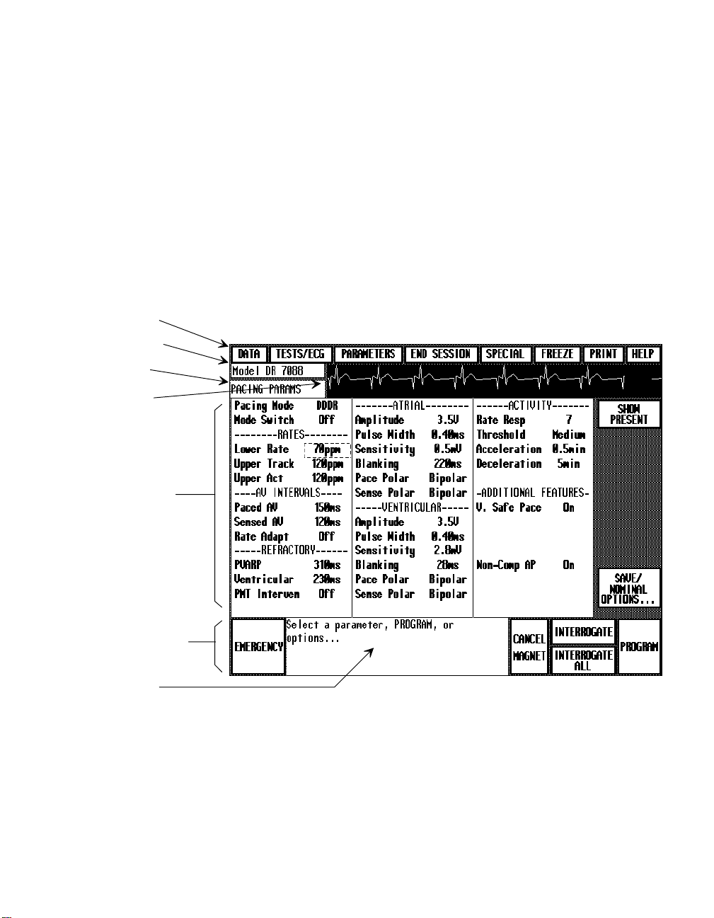
Display Screen Example
Below is an example of the screen format you will see when you select one
of these model options. The parameter list depends on the model selected.
Menu Buttons
Pacemaker ID
Screen Title
ECG Display
Function Display
Area
Command Buttons
Message Box
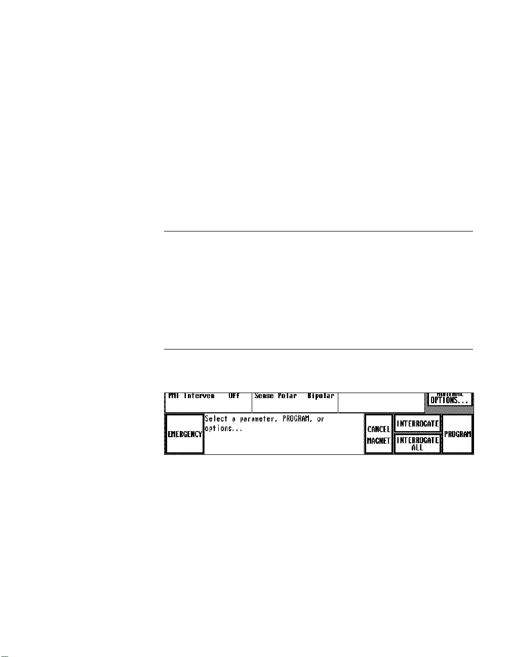
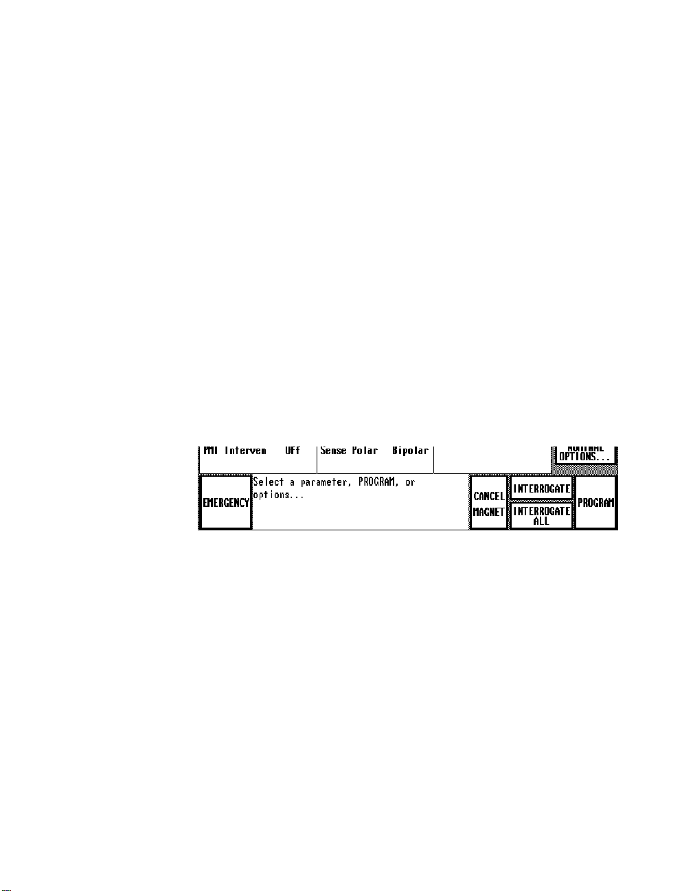
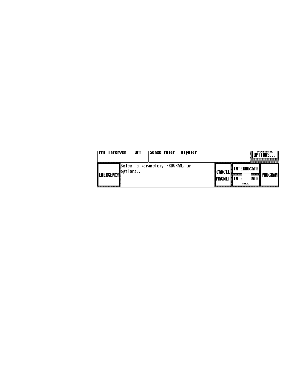
The main elements of this screen format are as follows:
Menu Buttons ó The menu buttons, which appear across the top of each
screen, provide direct access to the programmer functions. These buttons
replace the Main Menu screen, which applies to other pacemaker models.
Pacemaker ID ó Displays the pacemaker family name and model number.
Screen Title ó Title of the current screen generally appears in this
location.
Page 20

1-6 Using the Programmer
ECG Display ó This box continuously displays a low-resolution trace of
the patientís ECG.
Function Display Area ó This area of the screen changes according to the
selected function. It displays the data, buttons, and options that apply to the
selected function.
Command Buttons ó Location of the [
[
INTERROGATE], and [PROGRAM] buttons is the same for all pacemaker
applications. The [
screens; other buttons appear when the command is applicable.
Message Box ó The message box continuously displays procedural
prompts and status messages including warnings and precautions, when
appropriate. It is important to read the information presented in the
Message Box whenever you are operating the programmer.
EMERGENCY] programming button appears on all
EMERGENCY], [CANCEL MAGNET],
Interactive Screen Features
The interactive display screen features that respond to application of the
touch pen are: 1) on-screen buttons and 2) options that appear in boldface
type. The following are some examples of buttons and options.
Buttons appear as boldface words or
symbols enclosed within a heavy,
black rectangular border. Buttons
with labels ending in an ellipsis (...)
open a window of additional options.
Selectable options, which appear in
boldface type, include pacemaker
models, parameters, parameter
values, and menu options.
INTERROGATE
SETUP...
PARAMETERS
7088, 7089
Lower Rate
40 70 100
THRESHOLD TEST
PROGRAM
To select a button:
Without touching the screen, move the tip of the touch pen to a position directly over the button; then press the pen against the screen.
If the button is a ìlockingî button (one that remains selected), the
button label will change to reverse video to indicate that it is selected.
If a procedure directs you to ìpress and holdî a button, you must press
the touch pen against the button and continue to press for as long as
you want the related operation to continue.
Page 21

Using the Programmer with 7068, 7078, 7088/89, and 8088/89 Pacemakers 1-7
To select an option:
Without touching the screen, move the tip of the touch pen to a position directly over any part of the boldface option label (may be a word
or number); then press the pen against the screen.
Audible Signals
Certain events in the operation of the programmer will result in an audible
signal of one or two tones, or ìbeeps.î These signals are intended to alert
the user to the success or failure of an action.
Single Beep = Success
A single beep following an Interrogate command indicates that the
interrogation was successful.
A single beep following a Program command indicates that the programming was confirmed.
Two Beeps = Failure
Two beeps following an Interrogate command indicate that the interrogation was not successful.
Two beeps following a Program command indicate that the programming was not confirmed.
Two Low-Tone Beeps
Two low-tone beeps sound when the selected command cannot be
executed.
Single Short Beep
A short beep that coincides with pressing the
INTERROGATE
PROGRAM
or
key on the programming head indicates that the programmer acknowledges
the keystroke. If the keystroke is inappropriate, two low-tone beeps will
sound.
Page 22

1-8 Using the Programmer
A Guide to Using the Menu and
Command Buttons
Using the Menu Buttons
Menu Buttons
DATA
TESTS/ECG
Except for [
selecting a menu button at the top of the
screen displays a menu of related function
options. A check mark (✓✓✓✓) next to a
displayed option (see example at right)
indicates that option is currently selected.
NOTE: To close the menu without making a selection, ìclickî the touch
pen anywhere on the display screen outside the menu box.
Listed below is a description of the options accessible with each of the
menu buttons. Refer to the listed chapter for the procedure associated with
each option.
Retrieving Pacing System Data ó See Chapter 4.
Selecting the [
Displaying the Patientís ECG and EGM ó See Chapter 5.
END SESSION
DATA
] menu button displays options for:
Viewing a summary of interrogated data.
Viewing measured real-time values of battery and lead data.
Viewing a graph of accumulated diagnostic data (if applicable).
] and [
FREEZE
],
TESTS/ECG
Selecting the [
adjusting the patientís ECG and the EGM and Marker Channelô signals
received from the pacemaker via telemetry. The ECG display includes an
option for inhibiting the output of the patientís pacemaker.
Conducting Pacing System Tests ó See Chapter 7.
Selecting the [
Measuring stimulation thresholds.
Programming temporary parameter settings.
Measuring rate and AV interval.
TESTS/ECG
TESTS/ECG
] menu button displays an option for viewing and
] menu button also displays options for:
Page 23

Using the Programmer with 7068, 7078, 7088/89, and 8088/89 Pacemakers 1-9
Conducting electrophysiologic studies if 9886A or 9891A software is
installed. Instructions are covered in the EPS supplement supplied with
the 9886A or 9891A software.
PARAMETERS
PARAMETERS
END SESSION
SPECIAL
FREEZE
Programming Parameter Settings ó See Chapter 6.
Selecting the [
PARAMETERS] menu button displays options for:
Programming pacing parameters and viewing present settings.
Accessing additional parameter options including Extended Telemetry,
Transtelephonic Monitor, Serial Number, and Status Reset.
Setting Up the Diagnostics Function ó See Chapter 8.
Selecting the [
PARAMETERS] menu button also displays an option for
programming the pacemaker to record the selected type of diagnostic data.
Ending the Patient Session ó See Chapter 3.
Selecting the [
END SESSION] menu button lets you end the patient session
and return to the pacemaker model selection screen.
Special Options ó See Chapters 2 and 9.
Selecting the [
SPECIAL
] menu button provides access to the following
options:
A Position Head Assist option related to using the programming head
(Chapter 2).
A Calibrate option that sends a Marker Channel or EGM reference
signal to an externally connected recorder or monitor (Chapter 9).
Freezing the ECG Trace ó See Chapter 5.
PRINT
HELP
Selecting the [
FREEZE] menu button freezes a 10-second segment of the
patientís ECG and provides the option for viewing a Marker Channel
diagram if the pacemaker is operating in a permanently programmed dual
chamber or VDD pacing mode.
Printing Reports ó See Chapter 2.
Selecting the [
PRINT] menu button displays options for printing the various
data reports generated during the patient session.
Viewing Help Information ó See Chapter 2.
Selecting the [
HELP] menu button displays options for viewing information
about the currently displayed screen and other subjects related to using the
programmer.
Page 24

1-10 Using the Programmer
Using the Command Buttons
Listed below is a description of each of the command buttons located at the
bottom of the display screen. Refer to the listed chapter for the procedure
associated with using a particular command button.
Programming Emergency Parameters ó See Chapter 2.
EMERGENCY
Selecting the Emergency command overrides any function and immediately
programs the pacemaker to a fixed set of permanent values that provide
high output pacing in the VVI mode.
CANCEL
MAGNET
INTERROGATE
INTERROGATE
ALL
PACING
PARAMETERS
(not pictured)
PROGRAM
Canceling the Programming Head Magnet ó See Chapter 2.
Selecting the Cancel Magnet command cancels the effect of the program-
ming head magnet and allows the pacemaker to operate in its permanently
programmed state while the programming head is in position. For example,
operation of a pacemaker permanently programmed to the DDD mode will
change from the DOO magnet mode to the DDD mode when this command
is executed.
Interrogating the Pacemaker ó See Chapter 2.
Selecting the Interrogate command from a particular function screen
retrieves from the pacemaker the data related to that function.
Interrogating All Data ó See Chapter 2.
The Interrogate All command retrieves all data (parameter, battery/lead, and
diagnostic) from the pacemaker. This button appears only on the Pacing
Parameters screen.
Returning to the Pacing Parameters Screen
On screens other than the Pacing Parameters screen, this button appears in
place of [
INTERROGATE ALL
]. Selecting this button returns you directly to
the Pacing Parameters screen.
Programming Command ó (Covered in the respective procedures).
This command executes a temporary or permanent programming transmis-
sion based on the procedure being conducted. This button appears only
when programming is allowed.
Page 25

CHAPTER 2
Procedures to Know
Before You Begin
About This Chapter
This chapter covers some procedures that you might use at any point during
a patient session. You should be familiar with these procedures before you
begin a patient session. These procedures include:
Using the programming head (see page 2-2).
Programming Emergency parameters (see page 2-5).
Interrogating the pacemaker (see page
Canceling the effect of the programming head magnet (see page
Printing reports during a patient session (see page
Printing reports after a patient session has ended (see page 2-12).
Transferring session data to a computer diskette (see page 2-12).
Using the HELP options (see page
2-15
2-6
).
).
).
2-9
2-8
).
2-1
Page 26
2-2 Using the Programmer
Using the Programming Head
In many of the procedures described in the following chapters, you will be
directed to position the programming head over the patientís pacemaker.
Always position the programming head prior to executing any command that results in a programming or telemetry interaction between
the programmer and the pacemaker.
Improper positioning of the programming head could result in the
inability to program the pacemaker or to receive telemetry.
Positioning the Programming Head
CAUTION: Do not position the programming head over an implanted
pacemaker during electrocautery or defibrillation procedures.
IMPORTANT: Pacemaker operation will return to its permanently programmed settings about 2 seconds after you remove the programming head
from its position over the pacemaker.
For an implanted pacemaker, the programming head should be held directly
against the patientís skin with the face of the programming head parallel to
the pacemaker. Optimum position of the programming head may not be
directly centered over the pacemaker.
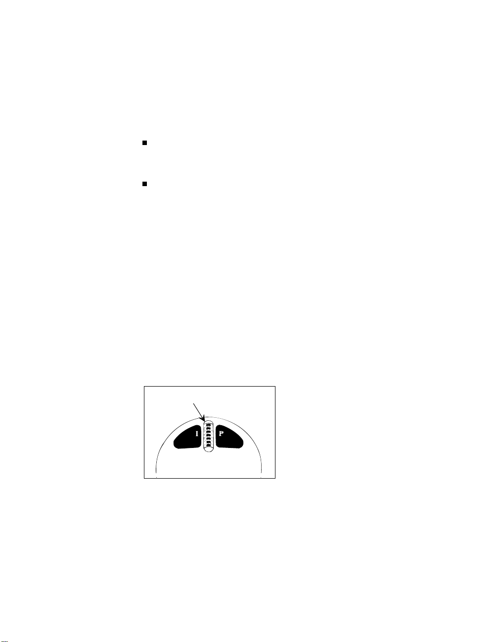
Light Array
NOTE: The 9790 programmer also has a programming head position
indicator light located near the display screen:
This indicator light is located near the upper left corner of the screen. This
indicator light also goes out when a telemetry link with the pacemaker has
been established ó or it may change from amber to green ó see Using the
POSITION HEAD ASSIST Option on the next page).
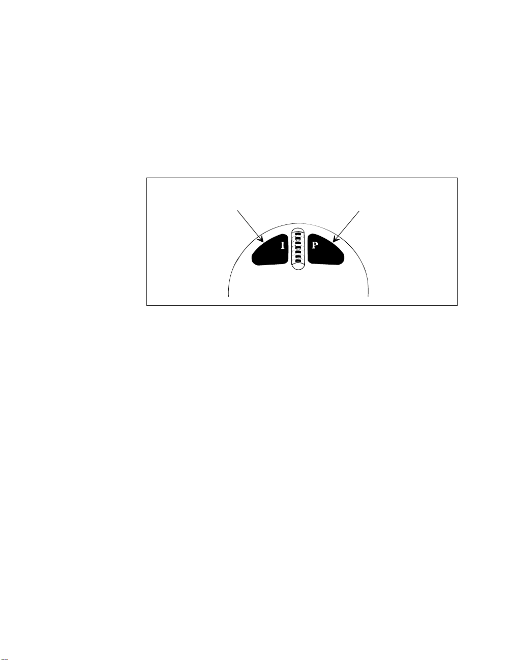
Position the programming head so that
the amber light in the light array on the
head goes out and one or more green
lights come on. Move the head to the
position that lights the greatest number
of green lights. This is the optimum
position.
Page 27
Procedures to Know Before You Begin 2-3
Using the POSITION HEAD ASSIST Option
The Position Head Assist function facilitates using the programming head
position lights to locate the optimum head position over the patientís pacemaker. This function is particularly useful under conditions that adversely
affect the communication link between the programmer and pacemaker.
NOTE: When the Assist function is enabled (ìEnhancedî option), continuous interaction between the programmer and pacemaker can cause extraneous artifacts to appear at 250 ms intervals on the patientís ECG trace. The
9790 programmer automatically filters these artifacts so they do not appear.
Although these artifacts can obscure pacing artifacts or small details on the
ECG trace, they have no effect on the pacing operation of the pacemaker.
The default setting for the Assist function is Enhanced. That is, the Assist
function will already be in effect when you start a patient session. If this
function results in extraneous artifacts on other monitoring devices connected to the patient, you can turn the Assist function off by selecting the
ìNormalî option as described below.
NOTE: If the Assist function is enabled, the programming head position
indicator on the 9790 programmer display panel changes from amber to
green when the programming head is properly positioned. If the Assist
function is disabled, the amber light goes out when the programming head
is positioned. The light array on the programming head operates the same
with or without the Assist function.
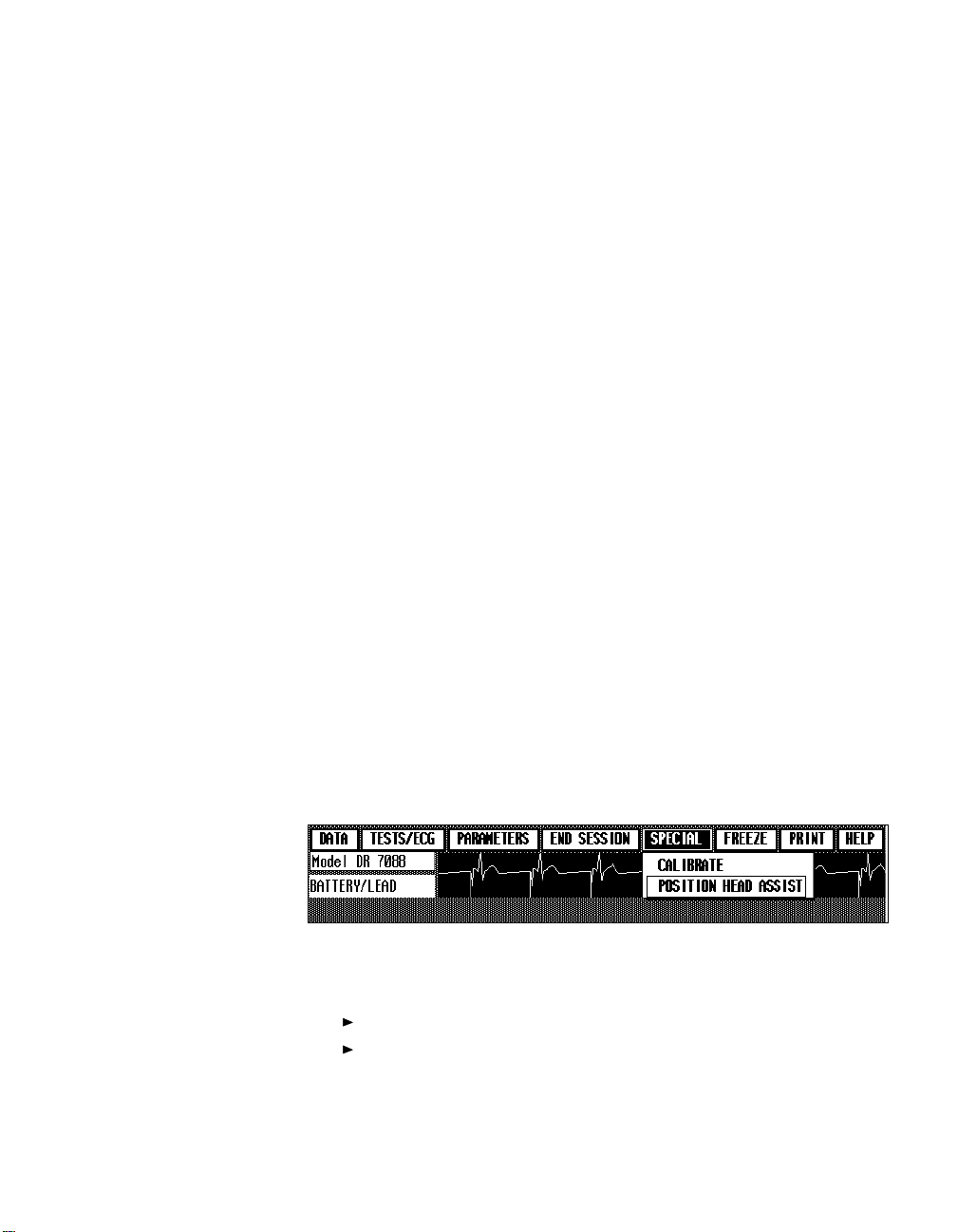
Position Head Assist
Option
Procedure for Selecting the Position Head Assist Setting
1. Select [
2. Select
SPECIAL
POSITION HEAD ASSIST
] from the menu buttons at the top of the screen.
from the options displayed.
3. From the window showing two buttons:
Select [
Or select [
ENHANCED
NORMAL
] to enable the Assist function.
] to disable the Assist function.
Page 28
2-4 Using the Programmer
Programming Head 9790 Programmer
Using
The
same function as the [
the display screen. Whenever the instructions in this manual direct you to
select the [
press the corresponding key on the programming head instead, if it is more
convenient.
PROGRAM
PROGRAM
PROGRAM
INTERROGATE Key
INTERROGATE
and
and
PROGRAM
INTERROGATE
] or [
INTERROGATE
keys on the programming head have the
INTERROGATE
] and [
] button on the screen, you can
PROGRAM Key
Keys
] buttons that appear on
Page 29
Procedures to Know Before You Begin 2-5
Programming Emergency Parameters
The Emergency programming command is a safety feature that overrides
all†other functions and immediately programs the pacemaker to preset
emergency values intended to provide pacing support under a variety of
conditions. This programming cancels any temporary function in effect and
restores magnet mode operation.
Emergency values are permanent settings that provide higher-than-normal
energy output. It is not intended that the pacemaker be left at these settings.
Emergency Button
Pacing Mode VVI
Rate 70 ppm
V. Refractory Period 330 ms
V. Pulse Amplitude 7.5 V
V. Pulse Width 1.5 ms
V. Sensitivity 2.8 mV
V. Pace Polarity Unipolar
V. Sense Polarity Unipolar
Single Chamber Hysteresis OFF
EMERGENCY
The [
screens.
] button appears in the lower left corner of all function
Emergency Values
↑↑↑↑
To program Emergency parameters:
1. Position the programming head over the pacemaker.
2. Select the [
left side of the display panel.
EMERGENCY
] button or press the square red button on the
3. Hold the programming head steady until a confirmation message
appears. If programming is not confirmed, verify that the programming
head is properly positioned and then reselect [
EMERGENCY
].
Page 30
2-6 Using the Programmer
Interrogating the Pacemaker
Before the programmer can display any information about the status of
the†patientís pacing system, you must interrogate the pacemaker. The
information you can retrieve by interrogating the pacemaker falls into three
categories:
1. Parameter settings
2. Real-time measurements of battery and lead data
3. Diagnostic data.
As described below, you can retrieve this information all at once or
separately as it is needed.
The INTERROGATE ALL Function
The Interrogate All feature retrieves all three types of information for use
during the patient session. This feature may be most helpful at the start of a
patient session, but it can be used at anytime during the session.
Interrogate All
Button
Available on the Pacing
Parameters Screen
↑↑↑↑
To execute the Interrogate All command:
1. Select the Pacing Parameters screen (see page 4-2 or 6-2).
NOTE: The Pacing Parameters screen is the first screen to appear
following model selection at the start of a patient session.
2. Position the programming head over the pacemaker.
3. Select the [
ming head steady until success of the interrogation is confirmed.
Auto Printout ó An Interrogate All command automatically initiates
printing of the following data: 1) the present programmed pacing and
diagnostic parameter settings, 2) a data summary report which includes an
Event Summary, and 3) Battery/Lead status data. Accumulated diagnostic
data is not included in this printout.
INTERROGATE ALL
] button. Continue to hold the program-
Page 31
Interrogate Button
Procedures to Know Before You Begin 2-7
NOTE: Executing an Interrogate All command automatically saves the
present programmed parameter settings. From a parameter programming
screen, you can view the saved values applicable to that screen (select the
[
SHOW SAVED] button) or you can recall the values to the screen as pending
values for programming (select the [
then select the [
SAVED VALUES] button).
SAVE/NOMINAL OPTIONS
] button,
...
The INTERROGATE Function
From most function screens, you can interrogate the pacemaker for the data
associated with that screen. Even when you have used the Interrogate All
feature, it may be necessary to perform additional interrogations to update
the programmer as you conduct the patient session.
↑↑↑↑
To execute the Interrogate command:
1. Position the programming head over the pacemaker.
2. Select the [
INTERROGATE] button. Continue to hold the programming
head steady until success of the interrogation is confirmed.
Page 32

2-8 Using the Programmer
Canceling the Programming Head Magnet
ìCancel Magnetî is a temporary programming command that cancels the
effect of the programming head magnet. It allows the pacemaker to operate
in its permanently programmed mode (such as the DDD mode) while the
programming head is held in position.
CANCEL MAGNET
Cancel Magnet
Button
The [
function screens except the Battery/Lead screen described in Chapter 4.
To execute the Cancel Magnet command:
While the programming head is positioned over the pacemaker, select
1.
CANCEL MAGNET
the [
] button appears near the lower right corner of all
↑↑↑↑
] button.
2. Watch for the ìMagnet cancelledî message.
Continue to hold the programming head in place for as long as you
want†the magnet canceled. Lifting the programming head terminates
the Cancel Magnet function.
Page 33

Procedures to Know Before You Begin 2-9
Printing Reports During a Patient Session
PRINT
The [
generated during a patient session. Most data is temporarily stored for the
duration of the patient session and can be printed at any time during the
patient session. However, some types of data, particularly graphic data,
must be printed while it is displayed on the screen. All data stored in programmer memory is cleared when you start a new patient session.
Selecting a Print Option
] menu button lets you select and print various reports of the data
Print Options
Selecting a Print option may cause on-screen buttons, except [
to be unresponsive for several seconds while data is being formatted for
printing. (The formatting of Diagnostic graphs may take about half a
minute.) Selecting a Print option will cancel an ECG recording in progress.
To print a report, select the [
appropriate print option from the drop-down menu. All possible options
will be listed, but only those in bold face type are selectable. A report
cannot be selected until data for that report has been generated.
PRINT
] menu button, and then select the
EMERGENCY
About the Print Options
Current Screen Report ó If data is
available, selecting this option prints the
report for the function associated with
the presently displayed screen. For
example, selecting this Print option
while the Pacing Parameters screen is
displayed results in the printing of a
Parameter Values report. Use this
option to print graphic reports, which
are available only while the data is displayed. These reports include the
Diagnostic Graph, and Marker Channel Diagram.
],
Parameter Values ó Selecting this option initiates a printout of all
pertinent parameter values presently programmed and confirmed in the
pacemaker.
Page 34

2-10 Using the Programmer
Data Summary ó Selecting this option prints a summary of the interrogated data. Included are the event data accumulated since the last patient
session.
Battery/Lead Data ó Selecting this option initiates a printout of the
real-time measurements associated with the Battery/Lead data function.
Diagnostics Data Table ó This option prints the recorded Diagnostic data
in tabular form. This is the same data the programmer uses to create and
display the Diagnostic Graph.
Threshold Results ó Selecting this option prints the data accumulated
during a patient session from the use of the Threshold Test function. The
programmer can store up to 32 test reports for printing during a patient
session.
Measured Values ó Prints the most recent parameter values obtained from
using the Measure ECG function.
Waveforms ó Available only if the current screen is the Freeze screen.
This option prints a 10-second chart of frozen ECG and telemetry traces.
Waveform Segment ó Available only if the current screen is the Freeze
screen. This option initiates a printout of only that portion of the 10-second
frozen traces selected with the on-screen calipers.
Full Report ó Prints the data accumulated for printing during the patient
session. Reports included in this printout (if the data is available) are
Parameter Values, Data Summary, Battery/Lead Data, Threshold Results,
and Measured Values. This printout does not include data, such as waveforms or graphs, which can only be printed while the respective screen is
displayed.
Trace ... ó Selecting this option displays two buttons that let you turn the
printer ìTraceî mode on or off. The following section describes the printer
Trace mode.
Page 35

Automatic
Printing
with the Printer
Mode
To turn the printer Trace mode ON or OFF:
Trace
1. Select TRACE ... from the Print menu
2. From the Trace
3. Select
ME0T'PONIC
0700 PROGRAMMER
01/10/96 12:56
PACEMAKER MODEL: Modal DR 7088
BATTERY/LEAD
Battery St atll,s:
F."
PatlerY Current 19.0
Battery 1npedance
L.earl
Pulse
P111se Amplitude
01,tiut
lead
Lead
Pnclug Configure
AnT0
Pacing Mode DDD
I.nwer Rata
A.
A.
V.
Paced/Sensed AV
1en1e1l/Pace11 AV
Testing ...... 3.0
Testing
Testing
"'escin
Testing 1.0 V
Testing ...ª>
THRESHOLD TEST
MAGNET
TEMPORARY TEST
Pacing
I.aw"er Rate 40
A. Amplitude
_A.
A.
V.
VALUES
Iv Voltage
States
Duration 0.40
Energy 11.4 11.5 1,l
Current
impedance 480
AMPLITUDE
Anplitllrle
P,llae
Width 0.40 m
A"plltnde 3,5
=-=1 ª
-_>">
g i.5 V
CANCELLED
Mode
Pulse
Width 0.40
AMplttulle 3.6
OK
2.78 V
237
Atrial
4.00
7.7 7,9
BIPolar
THRESHOLD TEST
o0
3.5
150
150
2.5 V
2.0
0.5 V
COMPLETE
DDD
3.5
Sensitivity 0.5 mV
as desired.
Ventricular
0.40 ms
4.00 V
472
Bipolar
PPM
V
V
M.s
V
V
PPM
V
11
V
[EXIT]
13:07
p
olu
MA
1h,
13:08
13:08
13:06
13:08
options.
window,
select
MODE
or [TRACE MODE
ON]
[TRACE
to close the window.
Turning
automatically
during
as
the Trace mode on causes
print information
a
patient session. The use of such commands
Program, Interrogate,
Cancel
the printer to
as it is generated
Magnet, Emergency,
or Measure ECG are documented on the printout if
confirmation of
the command execution is received.
The parameters and values included in a
or measurement are printed as
program-ming, interrogation,
shown in this example.
Graphic information such as a
not printed
the Trace mode.
by
Diagnostic report is
the
Using
Trace mode
does not affect the option to print specific reports
manually.
During
the
printing
the Trace mode does not function.
generated while the programmer is
of
a real-time ECG
recording,
However,
printing
waveforms will be saved and printed when the frozen
waveform
Turning
printing
printout has completed.
the Trace mode off disables
feature.
Printing
will occur
this automatic
when you
only
select a specific Print option.
OFF]
data
frozen
Page 36

2-12 Using the Programmer
Printing Reports After a Session Has Ended
CAUTION: Selecting a pacemaker model to begin a new patient session or
turning the programmer off will clear all data accumulated in programmer
memory from the last patient session.
Procedure
Once you have ended a patient session, but before you select a new pacemaker model or turn the programmer off, you can print the reports accumulated during that session.
To print the data reports:
PRINT...
1. Select the [
button appears only if there is data present from the previous patient
session.
] button on the Automatic Model Select screen. This
2. Select [
PREVIOUS PATIENT DATA
pacemaker model until printing of the previous session data is
complete.
] from the option window. Do not select a
Transferring Session Data to a Diskette
CAUTION: Selecting a pacemaker model to begin a new patient session or
turning the programmer off will clear any data accumulated in programmer
memory from the last patient session.
Procedure
Once you have ended a patient session, but before you select a new pacemaker model or turn the programmer off, you can transfer the data reports
accumulated during the session to a computer diskette as described below.
NOTE: When you end a patient session, the Data Transfer To Disk window
(see next page) automatically may appear on the Automatic Model Select
screen. If this window shows, skip steps 1 and 2 of the procedure. If you do
not wish to use this function, select the [
CANCEL
] button.
Page 37

Procedures to Know Before You Begin 2-13
To save the data reports to a diskette:
1. Select the [
] button on the Automatic Model Select screen.
PRINT
...
NOTE: This button appears only if there is data present from the
previous patient session.
2. From the options displayed, select the [
DATA TRANSFER TO DISK] button,
which displays the window shown below.
The ìPatient ID,î which will be used in a printed header identifying the
data reports, defaults to the pacemaker serial number if applicable.
Otherwise, the pacemaker model number will show if it is available.
3. To enter a different patient identifier, select each character of the
ã
desired ID from the on-screen keyboard. Select the [
DELETE] button
≠
to delete an entered character.
Up to six characters of the patient ID will be used in the name of the
recorded data file.*
4. Insert a 3.5-inch computer diskette into the disk drive on the right side
of the programmer.
Diskette Requirements: Use a 3.5-inch computer diskette formatted to
be IBM compatible (formatted with MS-DOS or PC-DOS). Use a 720
Kb diskette (DS, DD) or a 1.44 Mb diskette (DS, HD)
5. Select the [
OK] button to copy the patient session data reports to the
diskette. If an error message appears, refer to ìDisk Error Messageî on
the next page.
*The name automatically assigned to the session file on the diskette will take the following
††format: DS######.MDS, where ì######î are the first six characters of the patient ID. If
††less than six characters are available, the extra spaces will be filled with zeros. If you save
††more than one file for the same patient on the same diskette, letters of the alphabet will be
††added to the file name to identify the order of each file. For example, the second file will
††have the name DS#####A.MDS, the third DS#####B.MDS, and so on.
Page 38

2-14 Using the Programmer
6. To remove the diskette, press the small, rectangular eject button near
Disk Error Message
If a disk error message occurs at step 5, check the following:
File Format
When you select the [OK] button, all available text reports from the last
patient session are saved to a file on the diskette in ASCII format. Included
in the file are all the character spacing, line feeds, and form feeds required
to print the saved reports in the same format used by the programmer. An
ASCII ìControl-Zî code will mark the end of the file.
NOTE: Do not select a pacemaker model or remove the diskette until
the file transfer process is complete. The message box will state when
data has been successfully transferred.
the disk drive opening.
Is the diskette the proper format? See step 4.
Is the diskette full or faulty? Try a new diskette.
Is the diskette write protected? Check the write-protect switch on the
back of the diskette.
Is the programmer in the process of printing? Selecting [OK] in this case
may result in an error message. Wait until printing has stopped.
The report file will include a header page showing the patient ID, file
format type (which will always be ì1î until other formats become available), and the pacemaker model number.
The saved file can be printed from an IBM-compatible computer using the
MS-DOS or PC-DOS PRINT command, or the file can be imported into a
word processing or data base program as an ASCII or DOS text file.
Using the Auto Prompt Feature
The ìAuto Promptî options (OFF and ON) displayed in the Data Transfer
to Disk window allow you to choose whether or not you want this window
to appear automatically when you end a patient session.
If you want the window to appear automatically as a reminder to save
the session data, select the Auto Prompt [
If you do not want the window to appear automatically, select the Auto
Prompt [
OFF
] button.
] button.
ON
Page 39
Using the HELP Options
Procedures to Know Before You Begin 2-15
Help Options
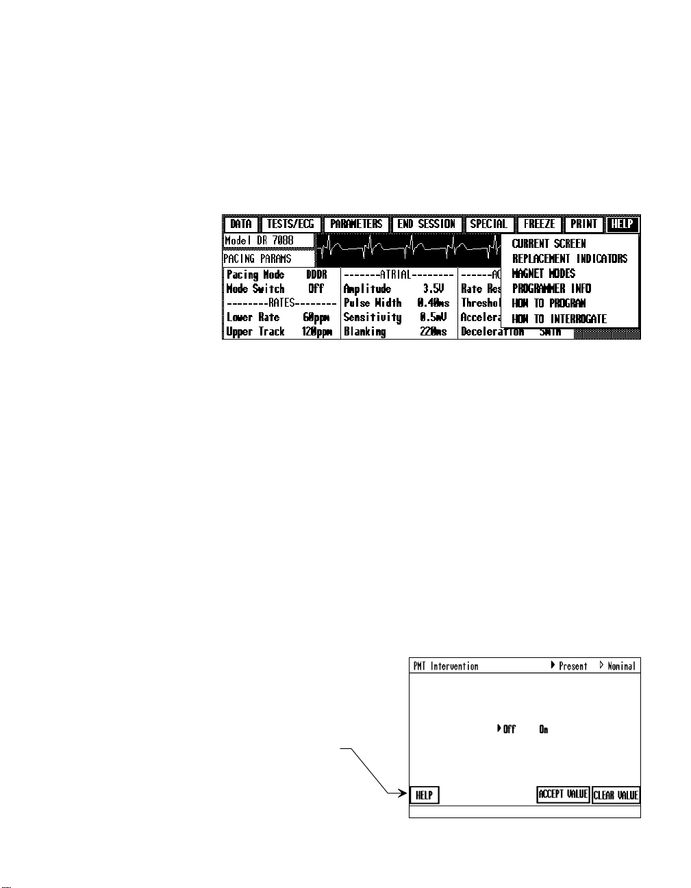
Selecting the [
about using the programmer. You can select the [
during the patient session.
Selecting one of these Help options opens a text window of pertinent
information:
Current Screen ó Information about the function screen that is presently
displayed.
Replacement Indicators ó Definitions of the battery status messages that
can appear for the selected pacemaker model.
Magnet Modes ó Information about the magnet modes and related pacing
rates for the 7068, 7078, 7088/89 and 8088/89 pacemakers.
Programmer Info ó Information about display conventions used to
convey information on the programmer display screen.
HELP
] Menu button displays options for viewing information
HELP
] button at any time
How to Program ó General instructions on how to program parameter
settings from the Pacing Parameters, Diagnostic Parameters, and Additional
Parameters screens.
How to Interrogate ó General instructions on how to interrogate the
pacemaker when it is required to display pacing data or parameter settings.
HELP
NOTE: A [
appears in the value selection
window for certain programmable parameters. Select this
button to view information
about that parameter.
] button also
Page 40

Page 41

CHAPTER 3
Starting and Ending a
Patient Session
About This Chapter
This chapter describes how to start a patient session, which involves:
Verifying the programmer setup and turning the programmer on (see
pages 3-2 and 3-3).
Selecting the pacemaker model (see page 3-4).
Using the menu buttons to proceed to a desired function (see page†3-7).
This chapter also describes how to properly end a patient session (see
page†3-9).
3-1
Page 42

3-2 Using the Programmer
Before You Begin
Prior to using the programmer in a patient session, verify that the programmer is properly set up. Refer to Chapters 2 and 3 in the ìProgrammer
Description and Setupî guide supplied with your 9790 programmer for
detailed instructions on setting up the programmer and preparing for a
patient session.
Programmer Setup Checklist
Verify that the following components are properly connected:
1. Programming head
2. Touch pen
3. ECG cable
4. Power cord (Connect the programmer to an appropriate power outlet.)
Connecting an External Monitor or Recorder
To connect an external monitor or recorder to the programmer, refer to the
instructions provided in Chapter 9 of this manual.
Connecting Skin Electrodes
For operation of the ECG measurement and display functions, the programmer must be connected to skin electrodes on the patient. Use an electrode
lead to connect each skin electrode to the appropriate port on the ECG
cable. Typical electrode placement is shown below.
RA (R)
RL (N)
LA (L)
C (C)
LL (F)
( ) = IEC Coding
Page 43

Starting and Ending a Patient Session 3-3
Turning the Programmer ON
Procedure
If the programmer is not operating, turn it on by pressing inward on the top
of the power switch. The power switch is located on the left side near the
back of the programmer.
System Self Test
Turning the programmer on results in a self test that takes about a minute or
less. Successful completion of the self test results in the Automatic Model
Select screen (see next page).
System Test Failure ó If during the self test the programmer displays a
ìSystem Test Failureî message, contact your Medtronic representative. This
message indicates that programmer service is required.
Printer Test Failure ó If the self test discovers a fault within the printer,
the programmer will continue to operate, but the printer will be disabled.
Printer service may be required. Contact your Medtronic representative.
System Setup Options
Refer to Chapter 9 of this manual for information about the system setup
options that are accessible from the Automatic Model Select screen, which
is displayed upon successful completion of the self test. The system setup
information covered in Chapter 9 includes:
Setting the time and date of the programmerís clock/calendar function.
Connecting an external recorder or monitor and using the Calibrate
option.
Setting up Site Nominal (user selected) parameter values for the 7068,
7078, 7088/89 and 8088/89 pacemaker model groups.
Setting the pacing artifact display function to on or off.
Page 44

3-4 Using the Programmer
Selecting the Pacemaker Model
The procedure for starting a patient session begins at the Automatic Model
Select screen shown in the example below. This screen appears after you
turn the programmer on as described in the previous section (or after you
select the [
To start a patient session, you must select the appropriate pacemaker model.
Automatic Model
Select Screen
With the programming
head in position, select
this button for automatic model selection.
For manual model
selection, select proper
button to display model
options.
END SESSION
] button to end a patient session).
NOTE: When you end a patient session, the Data Transfer to Disk window
may be superimposed on the Automatic Model Select screen. If you do not
wish to use the Data Transfer feature, select [
CANCEL
] to close the window
(see CAUTION below).
CAUTION: Selecting a pacemaker model or turning the programmer off
will automatically clear all data reports accumulated in memory during the
previous patient session.
If you wish to print these reports, refer to ìPrinting Reports After a
Session Has Endedî on page 2-12.
If you wish to transfer these reports to a computer diskette, refer to
ìTransferring Session Data to a Disketteî on page 2-12.
Page 45

Starting and Ending a Patient Session 3-5
Automatic Model Selection
To use the automatic model selection feature:
1. Position the programming head over the patientís pacemaker.
2. Select the [
INTERROGATE
AUTOMATIC MODEL SELECT
key on the programming head.
] button on the screen or the
NOTE: It is not necessary to select the applicable chamber. The
ATRIUM
[
] and [
VENTRICLE
] buttons on the Automatic Model Select
screen do not apply to the 7068, 7078, 7088/89 and 8088/89
pacemakers.
3. Continue to hold the programming head steady until a message at the
center of the screen confirms pacemaker identification.
Model Identified ó Upon automatic identification of the pacemaker model
(which takes a few seconds), the programmer begins ìloadingî the appropriate application program. This process may take up to 15†seconds.
Display of the Pacing Parameters screen (see next section) indicates that
model selection is complete and you may proceed.
NOTE: If the pacemaker model identified is not a 7068, 7078, 7088/89 or
8088/89 model, refer to the appropriate programming guide supplied with
the software installed in your programmer. The front cover of each guide
lists the pacemaker families covered in that guide.
Model Not Identified ó If a message states that the pacemaker model
cannot be identified, reposition the programming head and repeat step†2
above or use the Manual Model Selection procedure described below.
Automatic identification of the pacemaker model will not occur if the
programming head is not properly positioned or if the presence of strong
electrical interference interrupts telemetry between the programmer and
pacemaker.
Manual Model Selection
If the pacemaker model cannot be identified by the automatic model selection feature, select the pacemaker manually as follows:
1. From the Automatic Model Select screen, select the pacemaker type:
SINGLE CHAMBER MODELS
[
2. From the list of options displayed, select the desired pacemaker model
group.
DUAL CHAMBER MODELS
] or [
].
Page 46

3-6 Using the Programmer
Selecting the pacemaker model initiates loading of the appropriate application program. This process may take up to 15†seconds. Display of the
Pacing Parameters screen (see next section) indicates that model selection is
complete and you may proceed.
If there are more model options than can be displayed on one screen, a
[
MORE
] button appears in the lower right corner of the option
>>
window. Select this button to view more options.
NOTE: It is not necessary to select the applicable chamber. The
ATRIUM] and [VENTRICLE] buttons on the Manual Model Select screen
[
do not apply to the 7068, 7078, 7088/89 and 8088/89 pacemakers.
Page 47

Starting and Ending a Patient Session 3-7
Selecting the Desired Function
Selecting the pacemaker model displays the Pacing Parameters screen
shown in the example below. This screen allows you to:
View the present pacing parameter settings (see Chapter 4).
Program new pacing parameter settings (see Chapter 6).
Proceed to another function.
To proceed to another function, select the appropriate button from the
ìmenuî buttons displayed across the top of the screen. These buttons,
which†appear on all screens, let you quickly and easily access all functions
applicable to the selected model.
Menu buttons provide
easy access to all
applicable functions.
These buttons always
appear at the top of
every screen.
To display the present
parameter settings as
shown in this example,
you must interrogate
the pacemaker:
Position the
programming
head and press
INTERROGATE
[
INTERROGATE ALL
[
] or
Î
].
Navigating with the Menu Buttons
Except for the [
END SESSION
button displays a list of function options as described on the following
page.
] and [
FREEZE
] buttons, selecting a Menu
Page 48

3-8 Using the Programmer
Menu Button Description and Chapter Reference Possible Options
DATA
Select this button to display options for viewing
data retrieved from the pacemaker by interrogation, including: a pacing data summary, battery
and lead information, and a graph of Diagnostic
Data Summary (Ch 4)
Battery/Lead
Show Diagnostics Graph
data. Refer to Chapter 4.
TESTS/ECG
Select this button to display options for viewing
the patientís ECG and EGM and for conducting
various tests such as determining the patientís
stimulation threshold. Refer to Chapters 5
ECG/Markers/EGM (Ch 5)
Threshold Test (Ch 7)
Temporary Test (Ch 7)
Measure ECG (Ch 7)
and†7.*
PARAMETERS
Select this button to display options for programming pacing parameter values and for programming and using the Diagnostic function. Refer to
Pacing Parameters (Ch 6)
Diagnostic Parameters (Ch 8)
Additional Parameters (Ch 6)
Chapters 6 and 8.
END SESSION
Select this button to end a patient session.
SPECIAL
Select to access the Calibrate option, which
applies to using an external recorder, or to access
the Position Head Assist option, which applies to
Calibrate (Ch 9)
Position Head Assist (Ch 2)
using the Programming Head. Refer to Chapters
9 and 2, respectively.
FREEZE
Select this button to freeze a 10-second segment
of the patientís ECG. Refer to Chapter 5.
PRINT
HELP
*An ì
EPSî option for conducting electrophysiologic studies also will be listed if 9886A or 9891A software has been installed. ††Instructions for using EPS are covered in a programming guide EPS supplement supplied with the 9886A or 9891A
software.
Select this button to display
options for selecting the type
of report you want to print
or the printer Trace mode.
Refer to Chapter 2.
Current Screen Report
Parameter Values
Data Summary
Battery/Lead Data
Diagnostics Data Table
Threshold Results
Select this button to display options for selecting
informational help screens. Refer to Chapter 2.
Measured Values
Waveforms
Waveform Segment
Full Report
Trace ...
Current Screen (Ch 2)
Replacement Indicators
Magnet Modes
Programmer Info
How to Program
How to Interrogate
Page 49

Ending a Patient Session
The programmer accumulates and temporarily stores certain data generated
during a patient session. This data facilitates parameter programming and
provides for the display of session-related information. It is important to
properly end each patient session so that this data will clear from programmer memory when you select a pacemaker model to begin a new patient
session.
Starting and Ending a Patient Session 3-9
1. Select [
Menu button.
2. Select [
end patient session.
END SESSION
OK
] button to
To end a patient session, select [
END SESSION
] from the Menu buttons at the
top of the screen.
]
This action displays a window that allows you to verify your choice.
Select [
OK
] to end the session, or select [
CANCEL
] to continue the session.
Ending the session returns you to the Model Selection screen, which is the
starting point for the next patient session.
NOTE: Once you end a patient session, you have two options to retrieve
the data reports generated during that session. You can print the reports or
transfer the reports to a computer diskette (see page 2-12). Selecting a
pacemaker model to start a new patient session or turning the programmer
off will erase all accumulated data from the programmer memory.
Page 50

Page 51

CHAPTER 4
Retrieving Pacing System
Data
About This Chapter
This chapter describes how you can display information retrieved from the
pacemaker by interrogation. You can use the four procedures presented in
this chapter to display the following pacemaker information:
The present programmed parameter settings (see page 4-2).
Lead status and a summary of the programmed status of the Diagnos-
tics function. Included is a summary of certain event data automatically
collected in pacemaker memory (see page 4-5).
Real-time measurements of pacemaker battery condition and of
parameters related to pacemaker output and lead system status (see
page 4-9).
A graphic display of the event data accumulated in pacemaker memory
by the Diagnostics function if it has been programmed to collect data
(see page 4-11).
4-1
Page 52

4-2 Using the Programmer
Displaying Present Parameter Settings
You can quickly display the parameter settings to which the patientís
pacemaker is programmed by selecting the appropriate parameter screen.
There are three such screens: 1) The Pacing Parameters screen, 2)†The
Diagnostic Parameters screen , and 3) The Additional Parameters screen.
Displaying Pacing Parameter Settings
1. Select [
menu button.
2. Select
PARAMETERS
PARAMETERS
PACING
option.
Pacing Parameters
Screen
If the pacemaker has
been interrogated, this
screen displays the
presently programmed
pacing parameter
settings.
To display the Pacing Parameters screen, select the [
PACING PARAMETERS
button if it is displayed in the lower right corner of the present screen,
otherwise select the [
]
PARAMETERS
] menu button as illustrated below.
Parameter settings will not show unless an appropriate interrogation has
occurred. Interrogate the pacemaker, if necessary, to display the settings.
]
To use this screen to
program new pacing
parameter settings,
refer to the instructions
Page 53
Retrieving Pacing System Data 4-3
A Note About Mode Switch ó The subordinate parameter Detect Rate
associated with programming Mode Switch does not show on the Pacing
Parameters screen. To view the setting of this parameter, select Mode
Switch to open its value window. If Mode Switch is set to ON, the present
value for Detect Rate will show in the Mode Switch value window.
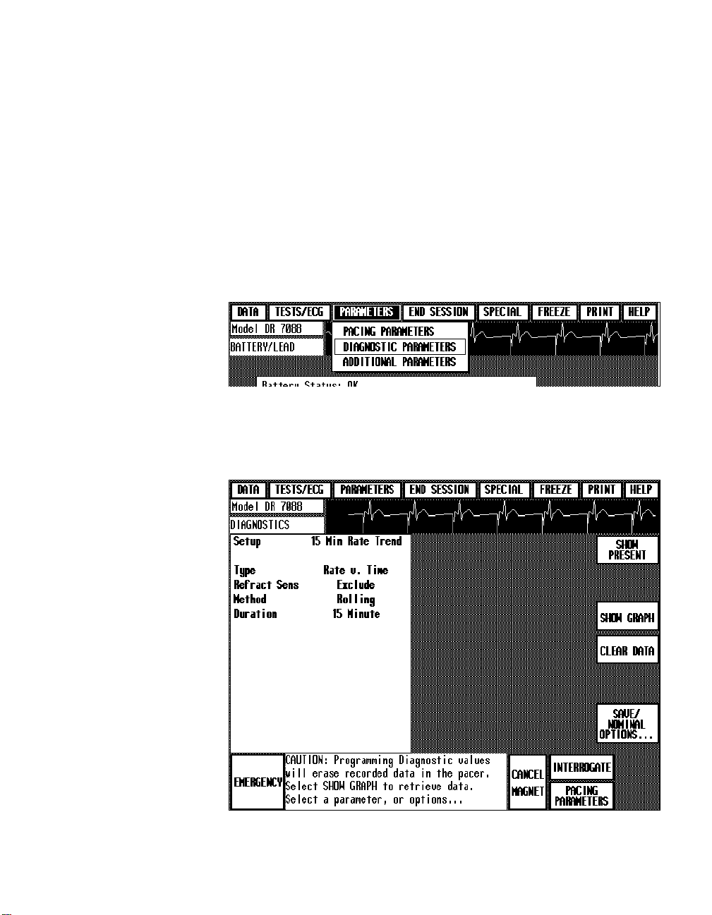
Displaying Diagnostic Parameter Settings
To display the present programmed parameter settings controlling the
Diagnostics function, select the [
select the
DIAGNOSTIC PARAMETERS
PARAMETERS
option as illustrated below.
] menu button, and then
1. Select [
menu button.
2. Select
PARAMETERS
Diagnostic Parameters
Screen
Interrogate the pacemaker, if required, to
display settings. Refer
to Chapter 8 for instructions on using the
Diagnostics function.
PARAMETERS
DIAGNOSTIC
option.
]
The Diagnostic Parameters screen appears as shown in the example below.
If the Diagnostics function has not been programmed to collect data, the
Type parameter will show a value of OFF.
Page 54

4-4 Using the Programmer
Displaying Additional Parameters Settings
The Additional Parameters screen displays the present settings for the
following parameters and provides access to the Status Reset command.
Transtelephonic Monitor (See Chapters 6 and 13)
Extended Telemetry (See Chapters 6 and 15)
Pacemaker Serial Number (See Chapter 6)
Status Reset (See Chapter 6)
1. Select [
2. Select
PARAMETERS
menu button.
ADDITIONAL
PARAMETERS
option.
Additional Parameters Screen
Interrogate the pacemaker, if required, to
display settings.
To use this screen for
programming these
parameters, refer to
Chapter 6.
For more about Transtelephonic Monitor and
Extended Telemetry,
refer to Chapters 13
and 15, respectively.
To display the Additional Parameters screen, select the [
menu button, and then select the
ADDITIONAL PARAMETERS
PARAMETERS
option as
illustrated below.
]
The Additional Parameters screen appears as shown in the example below.
]
Page 55

Retrieving Pacing System Data 4-5
Displaying a Summary of Pacemaker Status
You can display lead impedance and a summary of the programmed status
of the Diagnostics function by selecting the Data Summary screen. This
screen includes a display of certain event data automatically accumulated
by the pacemaker since the last patient session.
Selecting the Data Summary Screen
1. Select [
menu button.
2. Select
SUMMARY
DATA
DATA
option.
]
Data Summary
Screen
DIAGNOSTIC
], [
BATTERY
SHOW
], or [
Select the [
LEAD
PARAMETERS
DIAGNOSTICS GRAPH
button to view more
data.
To display the Data Summary screen, select the [
then select the
DATA SUMMARY
option as illustrated below.
DATA
] menu button, and
The Data Summary screen appears as shown in the example below. Data
will not be displayed unless an appropriate interrogation has occurred. If
necessary, interrogate the pacemaker to display the summary data.
/
]
Page 56

4-6 Using the Programmer
Battery/Lead
This section of the screen includes the present lead impedance. Lead
Impedance is the measured electrical impedance presented by the pacing
lead and electrode/tissue interface. If the pacing mode is a dual chamber
mode, the measured impedance for both lead systems is displayed.
Diagnostic Parameters
This section of the screen indicates the programmed status of the Diagnostics function by displaying the present settings of the Setup and Type
parameters. No value for Setup will be displayed if any changes were made
to the default settings established by the Setup option. A setting of ìOffî for
the Type parameter indicates that the Diagnostics function has not been
programmed to collect data.
Event Summary Data
Event Summary is a non-programmable pacemaker function that operates
continuously to collect the data described below. You can view this event
data only on the Data Summary screen and the Data Summary printout.
Event Summary shows data collected since the last patient session.
This data is automatically cleared from pacemaker memory during
each patient session and cannot be recalled once the session has
ended.
The listed dates, which show the period during which the event data
was collected, are based on the current setting of the programmerís
calendar function. Data collection stops when ERI occurs. In this case,
the ending date is labeled as the ìERIî date.
Under unusual circumstances, if a data error is detected, ìinvalid dataî
can show in place of certain event values. This condition should clear
itself by the next patient session.
Page 57

Retrieving Pacing System Data 4-7
% Total Events
The data under this heading shows the percentage of the total number of
recorded beats that fall into each of the displayed pace/sense event sequence
categories.
For dual chamber pacing modes, the event sequence categories are as
follows:
AS-VS
AS-VP
AP-VS
AP-VP
(Atrial Sense - Ventricular Sense)
(Atrial Sense - Ventricular Pace)
(Atrial Pace - Ventricular Sense)
(Atrial Pace - Ventricular Pace)
For the VDD mode, the event sequence categories are:
AS-VS
AS-VP
VS
VP
(Atrial Sense - Ventricular Sense)
(Atrial Sense - Ventricular Pace)
(Ventricular Sense preceded by a ventricular event)
(Ventricular Pace preceded by a ventricular event)
For single chamber modes, two event categories are used:
Paced
Sensed
PVCs
If the pacemaker has been operating in a dual chamber mode, Event Summary displays the counted number of PVC ìsinglesî and ìruns.î A PVC
(premature ventricular contraction) is defined by the pacemaker as a ventricular sense that follows a ventricular pace or sense without an intervening
atrial pace, atrial sense, or atrial refractory sense.
Singles
Runs
ó Show the number of singly-occurring PVCs.
ó Show the number of runs consisting of two or more PVCs.
A greater-than symbol (>) appearing in front of the displayed value indicates memory for this data is full and data collection has stopped. Since
PVC data collection applies only to dual chamber modes, this feature will
not be displayed if a single chamber mode was in effect during the monitoring period.
Mode Switch Episodes
ìMode Switch Episodesî is displayed in the Event Summary if the Mode
Switch parameter (see Chapter 14) applies to the pacing mode in effect
during the monitoring period. (Mode Switch applies only to the 7088/89
pacemaker models.)
Page 58

4-8 Using the Programmer
If Mode Switch is programmed ON, the number of mode switch episodes
occurring during the monitoring period is displayed. If the number of
episodes exceeds the range maximum (255), data collection stops, and a
greater-than symbol (>) appears in front of the displayed value.
If Mode Switch is programmed OFF, the display shows ìOffî in place of a
value.
Displaying More Data
To display more data,
BATTERY/LEAD
Select [
select the appropriate button as follows:
] to view all battery and lead measurements. See
next section, ìDisplaying Battery and Lead Information.î
DIAGNOSTIC PARAMETERS
Select [
] to view the programmed status of all
Diagnostic parameters. Refer to Chapter 8.
Select [
SHOW DIAGNOSTICS GRAPH
] to display a graph of the diagnostic
data recorded in pacemaker memory. (If the setting for Type is displayed as ìOFF,î no data has been collected for display.) Refer to
Chapter 8.
Page 59
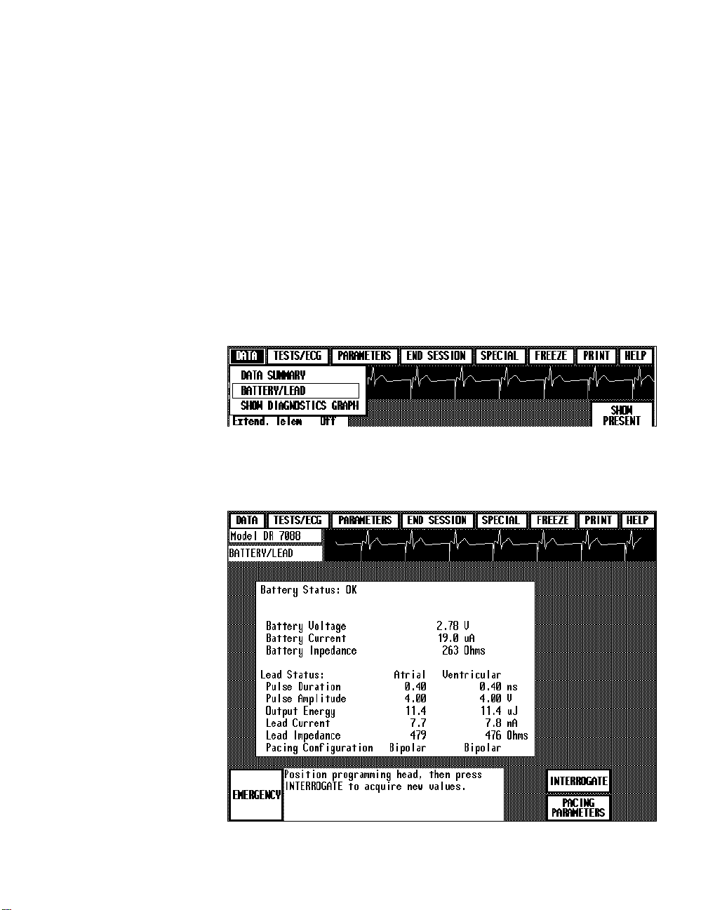
Retrieving Pacing System Data 4-9
Displaying Battery and Lead Information
By selecting the Battery/Lead screen, you can display information about the
pacemaker battery and lead system based on real-time measurements and
calculations made at the time of pacemaker interrogation. This information
provides a detailed status of the pacemaker battery and the output conditions pertaining to the pacing lead system.
Selecting the Battery/Lead Screen
1. Select [
menu button.
2. Select
LEAD
DATA
BATTERY
option.
]
/
Battery/Lead Screen
Interrogate the pacemaker if measurements
are not displayed. This
process may take
several seconds to
complete.
To display the Battery/Lead screen, select the [
select the
BATTERY/LEAD
option as illustrated below.
DATA
] menu button, and then
Data will not appear unless an appropriate interrogation has occurred.
Interrogate the pacemaker, if necessary, to display or update the battery and
lead data. Interrogation may require several seconds to complete.
Page 60

4-10 Using the Programmer
NOTE: During the measurement process, the pacemaker paces at 100 ppm
for several beats. (During these beats in a dual chamber mode, the AV
interval will be 100 ms.)
Parameter Measurements
The Battery/Lead screen displays a battery status message and real-time
measurements and calculations for the pacemaker parameters listed below.
Battery Status ìOKî or ìReplace Pacerî
Battery Voltage Present voltage of the pacemaker battery.
Battery Current Present current drain on the pacemaker battery
Battery Impedance Internal electrical impedance of the pacemaker
Pulse Duration Present programmed value of the pacing pulse
averaged over a pacing cycle.
battery.
width.
Pulse Amplitude Present value of the pacing pulse amplitude.
Output Energy Output energy contained in a single pacing
pulse.
Lead Current Current delivered during a pacing pulse.
Lead Impedance Electrical impedance presented by the pacing
lead and electrode/tissue interface.
Pacing Configuration Present programmed pacing configuration
(unipolar or bipolar).
Page 61

Retrieving Pacing System Data 4-11
Displaying a Graph of Recorded
Diagnostic Data
If the pacemaker has been previously programmed to record data for the
Diagnostics function, a graph of the data collected to date may be viewed
by selecting a Data option as described below. You can also display this
graph from the Diagnostic Parameters screen (see Chapter 8) or from the
Data Summary screen (see page 4-5).
Selecting the Graph Display Screen
1. Select [
menu button.
2. Select
DIAGNOSTICS GRAPH
option.
DATA
SHOW
]
Diagnostics Graph
The type of information
displayed by the graph
depends on the programmed status of the
Diagnostics function.
Refer to Chapter 8 for
information about the
Diagnostics function
and viewing the graph.
To print the graph, you
must select
SCREEN REPORT
the Print options while
the graph is displayed
(refer to Chapter 2).
CURRENT
from
To display the Diagnostics graph screen, select the [
and then select the
SHOW DIAGNOSTICS GRAPH
DATA
] menu button,
option as shown below.
The graph will not be displayed unless an appropriate interrogation has
occurred. Interrogate the pacemaker, if necessary, to display the graph.
Page 62

Page 63

CHAPTER 5
Displaying and Printing
the Patient’s ECG and
EGM
About This Chapter
The procedures presented in this chapter describe using the programmerís
ECG display and recording functions. The procedures describe:
How to print a real-time recording of the patientís ECG accompanied
by traces of Marker Channelô and EGM telemetry (see page 5-2).
How to select a high resolution display of the ECG and the Marker
Channel and EGM traces when present (see page 5-5).
How to inhibit pacemaker output to observe the patientís underlying
rhythm (see page 5-9).
How to freeze a 10-second segment of the patientís ECG and how to
use the on-screen calipers (see page 5-10).
How to select a Marker Channel Diagram to view more detailed
information about pacemaker operation (see page 5-14).
5-1
Page 64

5-2 Using the Programmer
Printing the Patient’s ECG and EGM
At any time during a patient session, you can initiate a continuous, real-time
recording of the patientís ECG as described below.
Procedure
NOTE: Step 1 will interrupt any report being printed. Likewise, selecting a
Print option from the display screen will interrupt and cancel an ECG
recording in progress.
1. To start a recording of the patientís
ECG, press the desired paper speed
button.
2. To stop the recording, press the
same button again.
3. Before you tear off the ECG strip,
press the
advance the paper to a perforation.
PAPER ADVANCE
button to
NOTE: Because the printed waveform recording provides a higher
resolution, it may show artifacts and events that do not appear on the
display screen.
Page 65

Annotations
ECG
Marker Telemetry
EGM Telemetry
Displaying and Printing the Patientís ECG and EGM 5-3
ECG Printout Example with Markers and EGM
About the Recording
Annotation of Executed Commands ó Information on the ECG printout
includes an indication of when certain commands to the pacemaker occurred. When confirmation of the command is received, the command name is
printed at the appropriate point in the margin above the waveform grid.
Parameter values are not printed except during a threshold test. A recording
made during threshold measurement will show each programmed test value
at the point it is programmed.
Marker Channelô and EGM Telemetry ó If the programming head is
over the patientís pacemaker, the recording will include a trace or traces of
the telemetry being received from the pacemaker. In the example above, the
patientís ECG is accompanied by ìMarkerî telemetry and EGM telemetry.
This combination of Marker and EGM telemetry (atrial EGM if the pacing
mode is dual chamber) is the default setting and occurs automatically when
you position the programming head. As described later in this chapter, you
can select other types of telemetry to be displayed and recorded.
ECG and EGM Trace adjustment ó The ECG and EGM are recorded
according to control settings accessible from the ECG/Markers/EGM
display described in the next section (the ECG/Markers/EGM display
appears on several screens). These control settings include ECG lead
configuration (Lead I, Lead II, or Lead III), amplitude scaling, and a filter
ON/OFF option.
Page 66

5-4 Using the Programmer
Missing Markers ó A programming command or interrogation momentarily interrupts the transmission of Marker Channel telemetry. This interruption can result in missing markers. The point at which the command
occurred is marked above the ECG trace by a ìdownî and/or ìupî arrow.
The down arrow (
mer; the up arrow (
Displaying Pacing Artifacts
During processing and amplification of the patientís ECG signal, the programmer automatically detects and enhances pacing artifact so that they
appear on the ECG display and printout. Under certain conditions, some
types of interference can trigger artifact detection causing false artifacts to
appear on the patientís ECG.
With the 9790 programmer, you can turn the artifact display on or off.
Turning the artifact display off allows you to monitor the patientís ECG
without the appearance of pacing artifacts. Disabling this function may be
advantageous in the presence of troublesome interference.
For instructions on turning the artifact display on or off, refer to ìSetting
the Artifact Displayî in Chapter 9. The Artifact Display options are
accessible via the [
▼) indicates a transmitted command from the program-
▲) indicates a telemetry response from the pacemaker.
SETUP
...
] button on the Automatic Model Select screen.
NOTE: With the artifact display turned off, pacing artifacts will not show
on the programmer ECG display or printout. Once you turn the artifact
display off, it will remain off until you repeat the procedure to turn it back
on.
Page 67

Displaying and Printing the Patientís ECG and EGM 5-5
Displaying the Patient’s ECG and EGM
By selecting the ECG/Markers/EGM screen, you can display a high resolution view of the patientís ECG. The ECG will be accompanied by a trace
of Marker Channel telemetry and EGM telemetry if such telemetry is being
received from the pacemaker. This screen provides waveform trace adjustment controls and an option for inhibiting pacemaker output.
Selecting the ECG/Markers/EGM Screen
1. Select the
TESTS/ECG
[
button.
2. Select the
ECG/MARKERS/EGM
option.
] menu
ECG/Markers/EGM
Screen
These buttons allow
adjustment of the ECG
and EGM traces and
selection of the
desired telemetry type.
To display this screen, select the [
/
ECG
the
MARKERS/EGM
option as illustrated below.
TESTS/ECG
] menu button, and then select
If the programmer is connected to skin electrodes on the patient, the screen
displays the patientís ECG as shown below. In this example, Marker and
ventricular EGM telemetry are being received from the pacemaker.
Page 68

5-6 Using the Programmer
Adjusting the ECG and EGM Traces
The control buttons at the left of the trace display (see below) let you adjust
the displayed ECG and EGM.
To make an adjustment:
1. Select the appropriate button (see descriptions below).
2. Select the desired option from the displayed window of options.
Select to choose a different ECG Lead configuration.
Options: Lead I, Lead II, Lead III (Lead II is the default setting.)
Select to change the ECG amplitude scaling.
Options: 1.0, 0.5, 0.2, 0.1, 0.05 mV/mm and Automatic.
ìAutomaticî sets scaling to the highest value that does not result in clipping
ECG LEAD II
1.0 mV/mm
Filter ON
75 bpm
of the waveform peaks. Automatic is the default setting.
Select to turn the ECG filter ON or OFF.
Options: Filter OFF (Bandwidth = 0.05 to 100 Hz)
The ON setting may improve clarity of the displayed and printed ECG in
the presence of interference. ìONî is the default setting.
____________________________
____________________________
Filter ON (Bandwidth = 0.5 to 40 Hz)
____________________________
V. EGM
1.0 mV/mm
Indicates the patientís present heart rate. This is not a control. The displayed value is a beat-by-beat measurement derived from Marker Channel
telemetry. For ventricular and dual chamber modes, the value will be the
ventricular rate; for atrial modes, the value will be the atrial rate.
_______________________________
Select to display programmable waveform telemetry options.
(See telemetry programming procedure next page).
____________________________
Select to change the EGM amplitude scaling.
Options for: A. EGM = 1.0, 0.5, 0.2, 0.1, 0.05 mV/mm and Automatic
V. EGM = 5.0, 2.0, 1.0, 0.5, 0.2 mV/mm and Automatic
ìAutomaticî sets scaling to the highest value that does not result in clipping
of the waveform peaks. Automatic is the default setting.
____________________________________________________________
Page 69

Displaying and Printing the Patientís ECG and EGM 5-7
Programming the Trace Telemetry Type
Default Telemetry
Positioning the programming head over the patientís
—
pacemaker automatically causes the pacemaker to transmit both Marker
telemetry and EGM telemetry (atrial EGM for dual chamber modes). The
combination of Marker telemetry and EGM telemetry is displayed in the
examples on pages 5-3 and 5-5.
Programming Procedure ó Use the following procedure to temporarily
program the telemetry to another type:
ECG LEAD II
1.0 mV/mm
1. With the programming head in position over
the pacemaker, select this button.
2. Select the desired telemetry type from the
Filter ON
75 bpm
V. EGM
options displayed (see below).
3. Continue to hold the programming head in
place for as long as you want to view the
programmed telemetry.
The telemetry type will return to its default
1.0 mV/mm
setting if the programming head is removed
from the pacemaker site for over 30 seconds.
Telemetry Options
The programmable options for the type of telemetry
—
that can be displayed and recorded with the patientís ECG are as follows:
A. EGM
V. EGM
MARKER
SENSOR
This option displays atrial EGM and Marker telemetry.
This option displays ventricular EGM and Marker
telemetry.
This option displays Marker telemetry only. The Marker
trace appears in a larger format on the lower trace display
in place of the EGM.
This option displays Sensor telemetry only. The Sensor
trace appears on the lower trace display in place of the
EGM. (Sensor telemetry does not apply to the Model
7068 pacemaker.)
Page 70

5-8 Using the Programmer
More About Marker Channel™ Telemetry
NOTE: An interrogation or programming command momentarily interrupts
Marker Channel telemetry. If this interruption occurs at the moment a
marker is scheduled, the marker is not displayed.
MARKER Telemetry ó A trace of Marker telemetry depicts pacemaker
operation by showing Pace, Sense, and Refractory Sense events as they
occur within the pacemaker. Markers also depict triggered pacing in the
AAT or VVT mode and the beginning and end of a Mode Switch episode
when it occurs. These markers are intended to facilitate interpretation of the
ECG. Each Marker is coded as follows:
Dual Chamber Models Single Chamber Models
AP
AS
AR
___________________________________________________________________
TP
MS
ER
= Atrial Pace
= Atrial Sense
= Atrial Sense
during refractory during refractory refractory
= Triggered Pace (AAT or VVT pacing mode)
= Mode Switch Episode (marks the beginning and the end)
= Error Marker (indicates a Marker signal that could not be decoded)
VP
= Ventricular Pace
VS
= Ventricular Sense
VR
= Ventricular Sense
P
= Pace
S
= Sense
SR
= Sense during
Example Display
Showing Sensor
Markers
While Sensor markers
are displayed, heart rate
is not measured. This
number remains fixed.
SENSOR Telemetry
(Does not apply to the Model 7068.) Sensor
—
telemetry transmits a single type of marker to show ìSensor-Detectî events.
A Sensor-Detect event occurs each time the detected level of physical
activity exceeds the programmed Activity Threshold setting. Sensor markers thus show response of the Activity sensor to physical activity of the
patient and are intended to facilitate evaluation of the Activity Threshold
setting.
Sensor markers appear on the lower trace display as shown in the example
below. These markers are not annotated with letter codes.
Page 71

Displaying and Printing the Patientís ECG and EGM 5-9
Inhibiting Pacemaker Output
INHIBIT
This button, which also appears on other screens
that show the ECG/Markers/EGM display, lets
you temporarily stop the pacing output of the
patientís pacemaker for such purposes as observing the underlying rhythm.
CAUTION: The Inhibit function is intended for diagnostic and test
purposes. It should be used only under conditions of careful patient
monitoring and control.
IMPORTANT: At any point during use of the Inhibit function, releasing
PROGRAM
the [
] button or lifting the programming head away from the site
of the pacemaker for at least two seconds will restore pacing output. In the
event of a programmer malfunction or loss of power, lift the programming
head immediately.
Pacemaker blanking periods are minimized during use of the Inhibit
function to increase the window during which cardiac events can be sensed.
Sense markers appearing below the ECG will indicate each sensed event.
Inhibit Procedure ó To inhibit pacemaker output:
1. Make any desired ECG trace adjustments before selecting [
INHIBIT
].
2. Position the programming head and hold it steady for the remainder of
this procedure.
NOTE: To observe Sense markers and a display of the sensed rate
while you use the Inhibit function, select the [
CANCEL MAGNET
] button.
(If pacemaker operation is not changed from the magnet mode, Sense
markers and the patientís intrinsic rate cannot be displayed.)
INHIBIT
3. Select [
4. To inhibit pacemaker output, press and hold [
] to prepare the programmer.
PROGRAM
].
A message indicates that the command is causing inhibition. The ECG
trace should show the absence of any pacing stimuli. To obtain an ECG
recording, press the desired paper speed key on the programmer.
5. To restore pacing output, release [
PROGRAM
].
Watch for confirmation that pacing output has been restored. If confirmation is not received, lift the programming head to ensure that pacing is
restored.
Page 72

5-10 Using the Programmer
Freezing the ECG Trace
At any time during a patient session, you can freeze and display 10 seconds
of the patientís ECG and the accompanying telemetry traces. On-screen
calipers let you accurately measure time intervals on these traces.
Selecting the FREEZE Button
To freeze and display a 10-second segment of the ECG and telemetry trace,
FREEZE
] menu button as shown below.
To freeze 10 seconds
of the patient’s ECG,
FREEZE
select the [
menu button.
]
select the [
This action displays the Freeze screen shown in the example below. The
frozen trace will begin to appear immediately or after a pause of 5 or 10
seconds, depending on the selected Freeze Option (see next page).
Freeze Screen
Buttons below the trace
display control the two
vertical cursors to
provide an on-screen
caliper function.
Page 73

Displaying and Printing the Patientís ECG and EGM 5-11
Selecting a Freeze Option
FRZ OPTION...
Timing of the 10-second window during which
ECG and telemetry signals are frozen depends
on the present Freeze Option setting.
Procedure ó To change the present Freeze Option:
1. Select the [
FRZ OPTION
...
] button to display the options and the present
setting.
2. Select the desired timing option (see below).
The selected setting takes effect the next time you use the Freeze
function and remains in effect until you change it.
Freeze Options ó Selecting the [
FRZ OPTION
...
] button displays the
following options:
Freeze Previous 10 Seconds
occurred just prior to selection of the [
Freeze Next 10 Seconds
occurs just after selection of the [
Freeze Previous 5 + Next 5 Seconds
trace that occurred prior to selection of the [
ó Freezes the 10 seconds of trace that
FREEZE
Freezes the 10 seconds of trace that
—
FREEZE
] button.
] button.
ó Freezes the 5 seconds of
FREEZE
] button plus the 5
seconds that occurs after the button selection.
Printing the Frozen Traces
Before you exit the Freeze screen, you can print the frozen 10-second trace
WAVEFORMS
(
calipers (
print option) or the portion of the trace between the on-screen
WAVEFORM SEGMENT
print option). Refer to Chapter 2 for in-
formation on printing reports.
Displaying a Marker Channel™ Diagram
SHOW DIAGRAM
This button lets you display a Marker Channel Diagram if the pacemaker is
programmed to a dual chamber or VDD mode and Marker Channel telemetry is being received. Refer to the last section in this chapter for information
about this diagram.
If the selected pacemaker is a dual chamber
model, this button appears on the Freeze†screen.
Page 74

5-12 Using the Programmer
Adjusting the Trace Displays
The control buttons at the left of the trace display let you individually adjust
the magnification of the frozen ECG and EGM waveforms and change the
time scale of trace display.
To make an adjustment:
1. Select the appropriate button (see below) to display a window of
2. Select the desired option from the displayed window.
____________________________________________________________
options.
ECG LEAD II
1.0 mV/mm
Magnify 1x
25 mm/sec
V. EGM
1.0 mV/mm
Magnify 1x
Indicates the present ECG Lead configuration and ECG amplitude scaling.
This is not a control.
____________________________
Select to change the frozen ECG magnification factor.
Options: 1X, 2X, and 4X (1X is the default setting.)
____________________________
Select to change the frozen display time scale.
Options: 25, 50, 100 mm/sec (25 mm/sec is the default setting.)
____________________________
Indicates the telemetry type displayed on the lower trace display and the
EGM amplitude scaling when applicable. This is not a control.
____________________________
Select to change the frozen EGM magnification factor.
*
Options: 1X, 2X, and 4X (1X is the default setting.)
____________________________________________________________
*This button does not appear if the present telemetry type shown in the box above it is
††ìMARKERî or ìSENSOR.î
Page 75
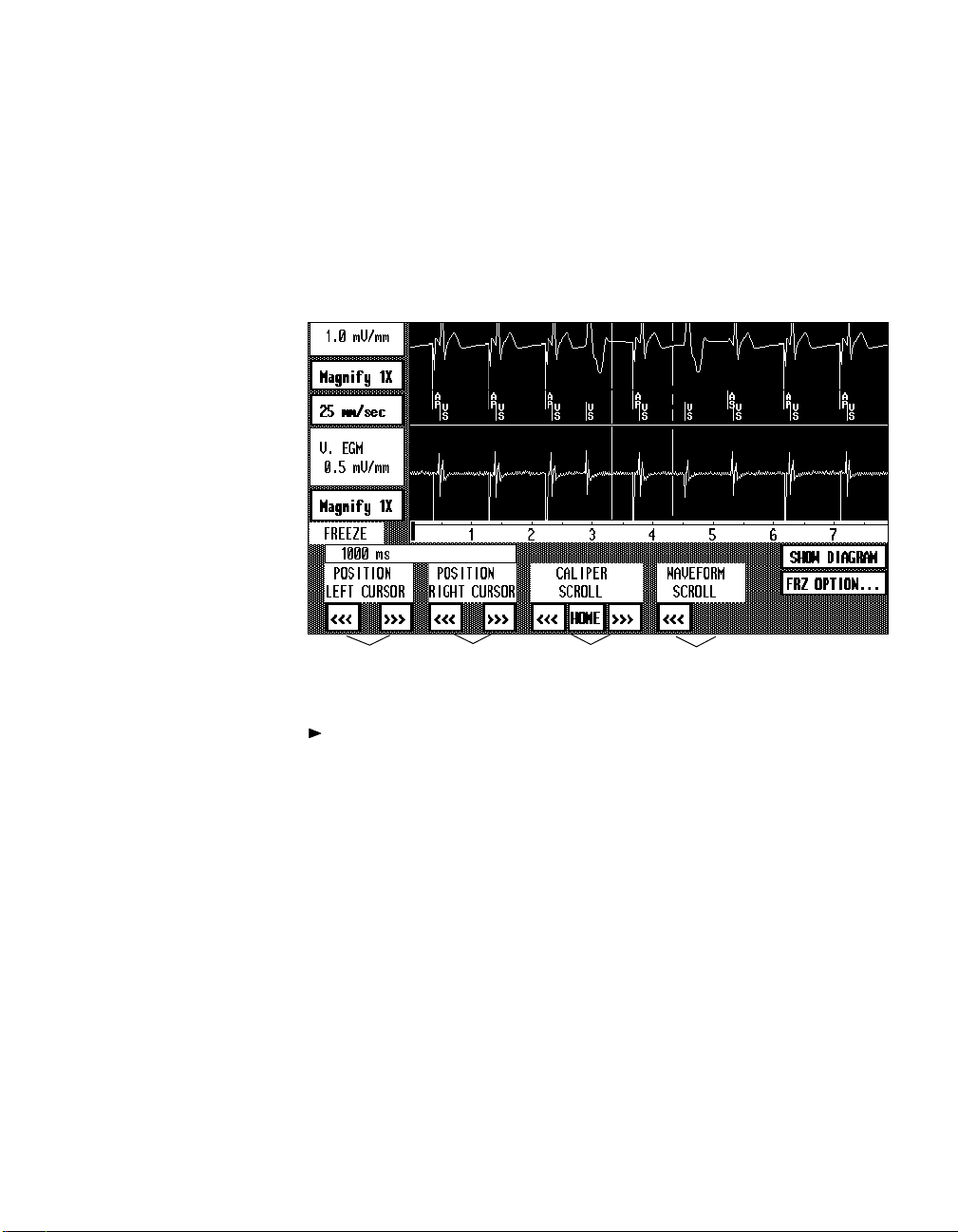
Freeze Screen —
Caliper Cursors
and Controls
Displaying and Printing the Patientís ECG and EGM 5-13
Using the On-Screen Calipers
The position and scroll buttons below the trace display let you control the
position of two vertical cursors appearing on the trace display. With these
controls, you can use the cursors as on-screen calipers to measure the time
interval between events on the displayed traces. The small window above
POSITION LEFT CURSOR
the
in milliseconds.
➎
buttons displays the interval between the cursors
Left Cursor
↓↓↓↓
↓
↓
Right Cursor
↓ ↓
ýýý➊ ýýý➋ эээээээээээ➌ ээээээ➍
To use the caliper position and scroll buttons:
Alternately press and release the appropriate button to effect small
movements or press and hold the button to effect larger movements.
Button action reference:
➊
These two buttons move the left cursor to the right or left.
➋
These two buttons move the right cursor to the right or left.
These buttons scroll the calipers to the right or left without changing
➌
the space between them.
Select the [
second apart. You can use this button to retrieve the calipers if they
have been scrolled off the screen.
To view the portion of the frozen traces not showing on the display,
➍
use these two buttons to scroll the waveform traces to the right or left.
This box displays the time interval between the cursors.
➎
HOME
] button to center the calipers on the screen one
Page 76

5-14 Using the Programmer
Displaying a Marker Channel™ Diagram
If the selected pacemaker is a dual chamber model, the Freeze screen
includes the†[
5-10. Under the proper conditions (see NOTE below), selecting this button
displays a Marker Channel Diagram.
NOTE: A Marker Channel Diagram can be displayed only if the pacing
mode is dual chamber or VDD and the display includes Marker telemetry
annotations (the selected telemetry type can be either Marker or EGM).
Selecting the Marker Channel™ Diagram
SHOW DIAGRAM
] button as shown in the example on page
Freeze Screen with
Marker Channel™
Diagram
To print the ECG trace
and diagram, select the
PRINT
] menu button, and
[
then select the
SCREEN REPORT
CURRENT
option.
SHOW DIAGRAM
To display a Marker Channel Diagram, select the
SHOW DIAGRAM
[
] button on the Freeze screen.
The diagram will be drawn on the lower trace
display as shown in the example below.
SHOW MARKERS/EGM
To return to the trace of Marker or EGM
plus Marker telemetry, select the [
/
MARKERS
place of the [
EGM
] button, which appears in
SHOW DIAGRAM
SHOW
] button.
Page 77
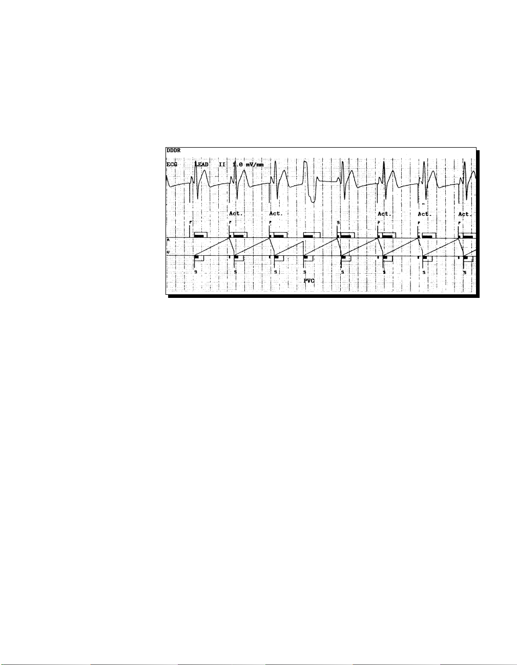
Example of a
Marker Channel™
Diagram Printout
Displaying and Printing the Patientís ECG and EGM 5-15
About the Marker Channel™ Diagram
The Marker Channel Diagram (see example below) shows more details of
pacemaker operation by depicting the various timing intervals, including
blanking and refractory periods. The diagram is intended to further clarify
operation of the pacemaker and simplify analysis of the patientís ECG.
NOTE: If events portrayed on the diagram occur in very rapid succession,
the Pace and Sense marker annotations (P, S, R) may not appear, and the
supplemental labels (Act., Safe, PVC, and NCAP*) that define certain
events may overlap. Overlapping characters or labels displayed on the
screen may not appear exactly the same on the printout.
NOTE: In situations where the event rate is unusually high, the Marker
Channel Diagram may be less than 10 seconds in length due to processing
limitations.
Using the On-Screen Calipers
Operation of the
WAVEFORM SCROLL
of this chapter.
POSITION LEFT/RIGHT CURSOR, CALIPER SCROLL
buttons is the same as described in the previous section
, and
Printing the Marker Channel™ Diagram
To print the Marker Channel Diagram, select the [
then select the
only while it is displayed on the screen.
*NCAP applies only to the 7088/89 pacemaker models.
CURRENT SCREEN REPORT
option. You can print a diagram
PRINT
] menu button, and
Page 78
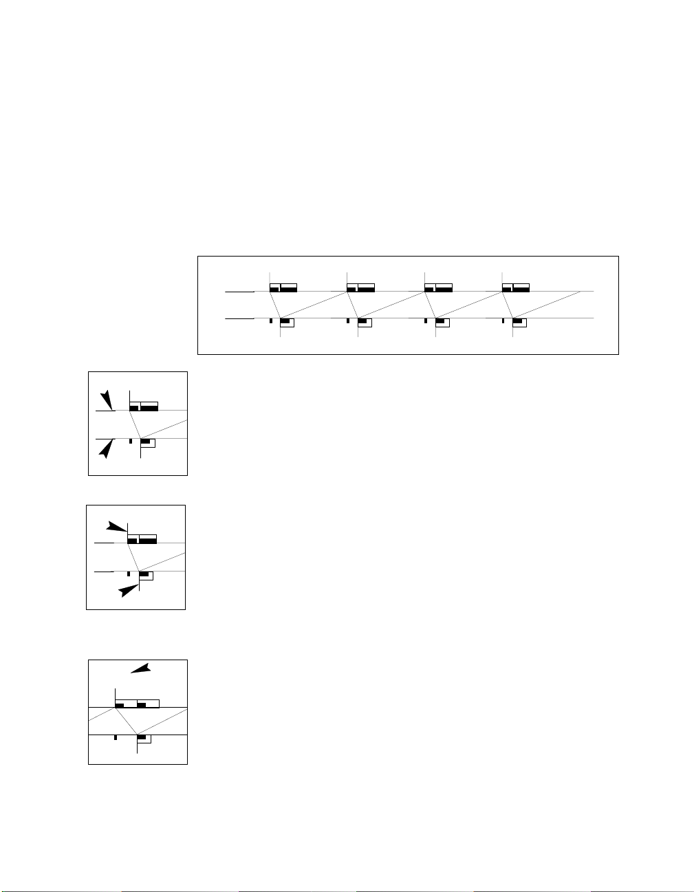
5-16 Using the Programmer
The printout lists the present parameter settings on which the diagram is
based and includes definitions of the lines, labels, and symbols used in the
diagram.
Interpreting the Diagram
Each Marker Channel Diagram is formed by a series of lines and symbols
that depict pacemaker operation. The pacing mode in effect is printed above
the ECG trace at the top of the chart.
P
A
V
P
P
Atrial and Ventricular Baselines ó The diagram is formed along two
P
P
P
P
P
P
parallel baselines labeled ìAî and ìV.î Symbols depicting atrial activity
A
V
appear along the top side of baseline A; symbols depicting ventricular
activity appear along the bottom side of baseline V. Sloped lines appearing
between the two baselines depict the timing relationship between atrial and
P
ventricular events.
Pace and Sense Markers ó Short vertical lines extending upward from
P
baseline A and downward from baseline V are the event markers received
via Marker Channel telemetry. Each marker is labeled according to the
A
V
P
event it represents.
P
S
R
ER
(Pace) Output of a pacing stimulus.
(Sense) A sensed event.
(Refractory Sense) An event sensed within the refractory period.
(Error) A marker that could not be decoded because of interference
or interrupted telemetry.
Act.
P
Supplemental Marker Labels ó Supplemental labels indicate when a
marker is the result of one of the following conditions:
Act.
Safe
PVC
P
NCAP
An activity-driven pace.
A ventricular safety pace.
A pacemaker-defined premature ventricular contraction.
A non-competitive atrial pace.
Page 79

Displaying and Printing the Patientís ECG and EGM 5-17
P
RS
Blanking and Refractory Periods ó Rectangles on the A and V baselines
depict atrial and ventricular blanking and refractory periods.
Solid Rectangles ó Depict blanking periods.
Open Rectangles ó Depict refractory periods. Vertical lines appearing
S
within the rectangle mark the timing of sense or pace events occurring in
S
the opposite chamber. Such lines may indicate the start of a new refractory
(and blanking) period.
P
Timing Lines ó The sloped, horizontal, and vertical lines appearing
between the A and V baselines depict the timing relationship between the
atrial and ventricular events.
Downward Sloping Lines ó Depict A-to-V timing (based on the pace-
P
makerís operating AV interval) initiated by an atrial pace or sense event.
The course of this line results in a ventricular pace, unless it is interrupted
by a ventricular sense.
P
Upward Sloping Lines ó Depict V-to-A timing (based on the pacemakerís
P
operating pacing rate) initiated by a ventricular pace or sense event. Except
as stated below, the course of this line results in an atrial pace unless it is
interrupted by an atrial sense or a PVC.
P
In the VDD pacing mode, a ventricular pace (not an atrial pace) occurs if
V-to-V timing completes before an atrial sense occurs.
SS
PS S
S
Horizontal Lines ó Depict any extension in the timing required to maintain
a proper pace schedule. In this example, the upper tracking rate results in an
extension of A-to-V timing. Another example is non-competitive atrial
pacing, which shows as an extension of V-to-A timing.
Timing extensions are common in diagrams of the DDI(R) mode because of
the absence of atrial tracking.
Vertical Lines ó Depict interruption of a timing interval by a sense or the
conclusion of a timing extension, which results in a pace.
Error Conditions
Under certain conditions, the programmer may not be able to properly
determine pacemaker operation from the data available. Most such conditions result in the appearance of an error message on the diagram.
Page 80

5-18 Using the Programmer
If an error message appears, you should reposition the programming head
and freeze another 10-second trace segment to obtain a new Marker Channel Diagram.
NOTE: A Marker Channel Diagram cannot be displayed if an interrogation
or programming transmission occurred during the 10-second interval of the
frozen trace.
Below is an explanation of the messages that indicate an error condition.
ìMissing Eventî ó This message appears if an event did not occur when it
was expected based on the interrogated data registered in programmer
memory. This situation can occur in the presence of interference that
interrupts telemetry.
Interruption of the diagram followed by the appearance of a Threshold
Margin Test (pacing at 100 ppm for three cycles) indicates that movement
of the programming head during recording of the 10-second frozen trace
opened and closed the pacemaker reed switch. In this situation, the Threshold Margin Test depicted on the diagram may be accompanied by one or
more ìMissing Eventî messages.
ìDiagram Errorî ó This message indicates that a particular sequence of
events portrayed by the Marker trace cannot be processed and properly
displayed by the Marker Channel Diagram.
ìBad Dataî ó This message indicates that the programmer has not
received the information it requires to complete the Marker Channel
Diagram. This can occur when there is an interruption or fault in the
telemetry being received - possibly due to interference or movement of the
programming head.
Page 81

CHAPTER 6
Programming Pacing
Parameters
About This Chapter
This chapter describes the following programming procedures:
How to program the permanent pacing parameters controlling operation of the patientís pacemaker. This procedure is conducted from the
Pacing Parameters screen (see page 6-2).
How to program nominal and saved parameter values (see page 6-6).
How to program the Transtelephonic Monitor and Extended Telemetry
parameters, which are related to follow-up procedures (see page 6-8).
How to program the Status Reset command to verify or clear an ERI
status or clear a pacemaker full electrical reset condition (see page 6-9).
How to program the pacemaker serial number in the event it is cleared
from pacemaker memory by an electrical reset (see page 6-10).
For instructions on programming the parameters of the Diagnostics
function, refer to Chapter 8.
6-1
Page 82

6-2 Using the Programmer
Programming Pacing Parameters
To program changes to the permanent pacing parameters, begin by
selecting the Pacing Parameters screen. This screen displays the present
parameter settings and lets you select the parameters and values to be
programmed.
Selecting the Pacing Parameters Screen
You can use either of two methods to select the Pacing Parameters screen:
select the [
corner of the present screen, otherwise select the [
button, and then select the
PACING PARAMETERS
PACING PARAMETERS
] button if it is displayed in the lower right
PARAMETERS
] Menu
option as shown below.
1. Select [
2. Select
PARAMETERS
menu button.
PACING
PARAMETERS
option.
Pacing Parameters
Screen
Refer to Part II of this
manual for specific
information about the
pacing modes and the
operation of certain
parameters.
Refer to Section E in
Part III for a list of the
parameters and values
available for each
]
Present settings will not be shown unless an appropriate interrogation has
occurred. Interrogate the pacemaker, if required, to display these settings.
Page 83

Programming Pacing Parameters 6-3
Features of the Pacing Parameters Screen
Parameter Display ó Following an interrogation, the screen shows the
present pacing parameter settings. The screen displays only those parameters that are applicable to the selected pacemaker model and pertinent to the
present pacing mode. Note that the parameters are divided into labeled
groups according to their general function.
PROGRAM
[
screen only when one or more new parameter values have been properly
selected (see ìRestricted Parameter Interactionsî below). The
key on the programming head will respond only when the [
button shows on the screen.
Special Options ó The three buttons located at the right of the parameter
display may be useful during the programming procedure described on the
next page.
] Button ó This button appears in the lower right corner of the
PROGRAM
PROGRAM
]
SHOW
PRESENT
When you select new parameter values to program, these
ìpendingî values are displayed in place of the interrogated
present settings. To temporarily recall the present settings,
press and hold this button.
SHOW
SAVED
If you have saved a set of parameter values (see below), this
button will appear on the screen. Pressing and holding this
button will temporarily display these saved values.
SAVE/
NOMINAL
OPTIONS...
Selecting this button displays options for: 1) clearing all
pending values from the parameter screen, 2) saving a set of
parameter values, and 3) recalling the set of saved values or
nominal values to the screen as pending values. (Refer to
ìProgramming Nominal and Saved Valuesî in this chapter.)
Restricted Parameter Interactions
Certain combinations of parameter values are restricted because they are
invalid or result in undesirable interactions. The programmer recognizes
these combinations and does not allow programming until all parameter
conflicts are resolved and all parameter selection requirements are met.
Refer to Section E in Part III for more information on parameter programming requirements and restrictions.
Restricted Parameter Values ó Any parameter value that conflicts with
the setting of a present or pending parameter is displayed in italics in the
parameter value option window (see step 2 of the programming procedure).
Page 84

6-4 Using the Programmer
Parameter Interaction ó If you select a restricted parameter value, the
DDIR
display will indicate the interacting parameter values by displaying the
values in reverse video. You must select new values to resolve the conflict
before programming is allowed.
Parameter Entry Requirement ó A solid, shaded rectangle appearing
where a parameter value should be displayed indicates that a valid value for
this parameter must be selected before programming is allowed.
General Parameter Programming Procedure
For specific parameter information related to
each pacemaker model, refer to Sections B
and†E of Part III.
To program one or more parameter values:
1. Select the desired parameter from those
displayed ó
Lower Rate
for example.
Press the touch pen directly over the
parameter name or its value.
NOTE: Select
Pacing Mode
first if you
intend to program a mode. Selecting a
mode displays the programmable parameters pertinent to that mode.
2. From the window of value options,
select the desired value.
Except for Hysteresis, selecting a value in
italics results in a restricted parameter
interaction.
Selecting a value closes the window. The
selected value appears in place of the
present value and is denoted as ìpendingî
by a dashed rectangle.
To clear a pending value from the screen,
select that parameter or value, and then
CLEAR VALUE
select [
] in the value window. To close the value window without
selecting a value, press [
ACCEPT VALUE
].
Page 85

Programming Pacing Parameters 6-5
3. Repeat steps 1 and 2 to include any other parameters you want to
program.
PROGRAM
NOTE:
If you try to exit the screen before you program the selected
values, a pop-up window will provide the option to continue with this
procedure or clear the pending values and exit the screen.
4. Position the programming head and select [
Select the [
PROGRAM
] button to program all pending parameter values.
PROGRAM
].
Hold the programming head in position until the confirmation message
appears.
NOTE:
If the programming is interrupted, it is possible that one or
more of the parameter groups will not be programmed and will still
show pending values. In such cases, the programming will not be confirmed, and the message box will direct you to reselect [
PROGRAM
].
Programming Mode Switch* ó If the present setting for Mode Switch is
or if you select ON, the value window lists the present setting for the
ON
subordinate parameter Detect Rate (see example below) and provides the
option to select a new value. Refer to Chapter 14 for information about the
operation of Mode Switch.
1. To select a value for Detect
Rate, use the same basic
procedure described in steps
1 and 2 of the general
programming procedure.
2. When you have selected the
desired value for Detect
Rate, select the [
VALUE] button to close the
ACCEPT
primary parameter value
window.
If the present or pending value for Upper Tracking Rate is 165 ppm or
above, the programmer automatically selects a pending value for Detect
Rate. The values of 185 and 190 bpm are not selectable but will respectively appear as the pending value if Upper Tracking rate is 175 or 180 ppm.
*Mode Switch applies only to the 7088/89 pacemaker models.
Page 86

6-6 Using the Programmer
Programming Nominal and Saved Values
The procedures below describe using the options available by selecting the
[
SAVE/NOMINAL OPTIONS
Programming Medtronic or Site Nominal Values
To recall Medtronic nominal settings (ìMedtronic Valuesî) or Site Nominal
settings to the screen as pending values for programming:
...
] button.
1. Select the [
2. Select [
MEDTRONIC VALUES
SAVE/NOMINAL OPTIONS
] or [
...
] button.
SITE NOMINALS
] from the window of
options.
The respective parameter values will appear on the screen as pending
values. You can directly program these values or make any desired changes
prior to programming.
NOTE: The [
SITE NOMINALS
] button shows only if Site Nominal values
have been set up for the selected pacemaker model. Refer to Chapter 9.
Saving a Set of Parameter Values
To save the displayed present pacing parameter values (those interrogated
from the patientís pacemaker):
1. Select the [
2. Select [
SAVE PRESENT VALUES
SAVE/NOMINAL OPTIONS
...
] button.
] from the window of options.
The displayed present parameter values will be saved in programmer
memory until you save another set of present values or end the patient
session. You can view the currently saved values by selecting the [
SAVED
] button on the Pacing Parameters screen.
NOTE:
INTERROGATE ALL
[
Unless some parameter values have already been saved, using the
] button as described in Chapter 2 will automatically
SHOW
save the present pacing parameter settings.
Programming the Saved Set of Values
To recall the saved parameter values to the screen as pending values for
programming:
1. Select the [
2. Select [
SAVED VALUES
SAVE/NOMINAL OPTIONS
] from the window of options.
...
] button.
The saved parameter values will appear on the screen as pending values.
You can directly program these values or make any desired changes prior to
programming.
Page 87

Programming Pacing Parameters 6-7
Programming Additional Parameters
Additional parameters include the Transtelephonic Monitor and Extended
Telemetry follow-up options, the pacemaker Serial Number, and the Status
Reset command. To access these parameter options, select the Additional
Parameters screen.
Selecting the Additional Parameters Screen
1. Select [
menu button.
2. Select
PARAMETERS
PARAMETERS
ADDITIONAL
option.
Additional
Parameters Screen
To display the Additional Parameters screen, select the [
menu button, and then select the
ADDITIONAL PARAMETERS
PARAMETERS
option as shown
below.
]
Parameter settings will not show unless an appropriate interrogation has
occurred. Interrogate the pacemaker, if necessary, to display the settings.
]
Page 88

6-8 Using the Programmer
Programming Transtelephonic Monitor
Transtelephonic Monitor is a feature that can facilitate using transtelephonic
monitoring during a remote patient follow-up procedure. The programmable options for this feature are ON and OFF. Refer to ìEnhanced Transtelephonic Monitoringî in Chapter 13 for an explanation of this feature.
WARNING: Do not program Transtelephonic Monitor to ON if the patient
has an implantable defibrillator (see Chapter 13).
To program Transtelephonic Monitor:
1. Select
Trans Tele
from the parameters listed on the Additional Pa-
rameters screen.
2. From the displayed window of options, select
3. Position the programming head and select [
PROGRAM
ON
or
as desired.
OFF
]. Hold the pro-
gramming head steady until you receive a programming confirmation.
Programming Extended Telemetry
Programming Extended Telemetry to ON will cause the pacemaker to
continuously transmit EGM and Marker Channel telemetry for 24 hours.
Refer to Chapter 15 for information about Extended Telemetry.
NOTE: Because Extended Telemetry increases current drain on the pacemaker battery, it should be used only when necessary.
To program Extended Telemetry:
1. Select
Extend. Telem
Parameters screen.
2. From the displayed window of options, select
3. Position the programming head and select [
gramming head steady until you receive a programming confirmation.
from the parameters listed on the Additional
ON
OFF
or
as desired.
PROGRAM
]. Hold the pro-
Page 89

Programming Pacing Parameters 6-9
Programming the Status Reset Command
For information about the Elective Replacement Indicator (ERI) or about
Electrical Reset, refer to the respective sections in Chapter 16.
Verifying or Clearing an ERI Status
If a screen message indicates that the pacemaker Elective Replacement
Indicator (ERI) has been set, you can use the Status Reset command to
verify present battery status as follows:
1. Select the
Status Reset
from the parameters listed on the Additional
Parameters screen.
RESET
2. From the option window, select
3. Position the programming head and select [
.
PROGRAM
]. Continue to
hold the programming head steady while the pacemaker automatically
tests the present condition of its battery.
During this test, the pacemaker paces asynchronously at 100 ppm for
several beats. (During these beats in a dual chamber mode, the AV
interval will be 100 ms.)
If the test verifies the ERI status, no reset will occur.
If battery voltage has recovered, the ERI status is cleared, and you
can proceed to reprogram the parameter settings.
Clearing a Pacemaker Electrical Reset
The Status Reset command can also be used to clear a full pacemaker
electrical reset condition. Indication that a full electrical reset has occurred
is VVI pacing at 65 ppm and, in some cases, a pacemaker serial number set
to all zeros (000000). Refer to Chapter 16 for an explanation of ìfull electrical resetî versus ìpartial electrical reset.î
IMPORTANT: If a full electrical reset has occurred , you should contact
your Medtronic representative after using the Status Reset command to
clear this condition.
To clear a full electrical reset condition:
1. Select the
Status Reset
from the parameters listed on the Additional
Parameters screen.
RESET
2. From the option window, select
3. Position the programming head and select [
.
PROGRAM
]. Continue to
hold the programming head steady until confirmation is received.
All parameters, including the pacemaker serial number, can now be reprogrammed to their proper settings.
Page 90
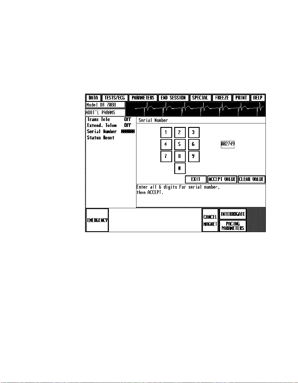
6-10 Using the Programmer
Programming the Pacemaker Serial Number
Serial number programming should not be used to change the factory
setting. This procedure is intended only for reprogramming the original
serial number in the unlikely event it is lost from pacemaker memory due to
a pacemaker electrical reset (see previous section about programming the
Reset command).
To reprogram pacemaker serial number:
1. Select
Serial Numbe
from the list of parameters on the Additional
r
Parameters screen.
2. Using the on-screen keypad, enter each digit of the original serial
number. The selected numbers will appear in the small window to the
right of the keypad.
3. If you make a mistake, select [
ACCEPT VALUE
[
] to register the entered number as a pending value.
CLEAR VALUE
4. Position the programming head and select [
]. Otherwise, select
PROGRAM
]. Hold the pro-
gramming head steady until you receive a programming confirmation.
Page 91

CHAPTER 7
Determining and
Evaluating Parameter
Settings
About This Chapter
Capabilities of the programmer include test and measurement functions that
can assist you in determining appropriate parameter values for programming the pacemaker or optimizing its operation. This chapter covers the
following test procedures.
Measuring the patientís stimulation threshold to determine appropriate
values for amplitude and pulse width (see page 7-2).
Using temporary parameter programming to evaluate other parameter
values without changing the permanent settings (see page 7-10).
Directly measuring the actual values of the pacing rate and paced AV
interval (see page 7-13).
7-1
Page 92

7-2 Using the Programmer
Measuring Stimulation Thresholds
The Threshold Test function lets you measure the patientís stimulation
thresholds to determine appropriate settings for amplitude and pulse width.
This measurement procedure begins at the Threshold Test Start screen.
Selecting the Threshold Test Start Screen
1. Select [
2. Select
TESTS/ECG
menu button.
THRESHOLD
TEST
option.
]
Threshold Test Start
Screen
In this example, the
programming head has
been positioned over
the patient’s pacemaker
to display Marker
Channel and EGM
telemetry.
Refer to pages 5-6 and
5-7 for instructions on
adjusting the ECG and
telemetry traces.
Selecting a chamber/
mode option and the
desired test type are the
first two steps in conducting a threshold test.
To display the Threshold Test Start screen, select the [
button, and then select the
THRESHOLD TEST
option as illustrated below.
TESTS/ECG
If you have not yet interrogated the pacemaker for its present parameter
settings, a message will prompt you to do so at this point. If this prompt
appears, position the programming head and select [
INTERROGATE
proceed.
] menu
] to
Page 93
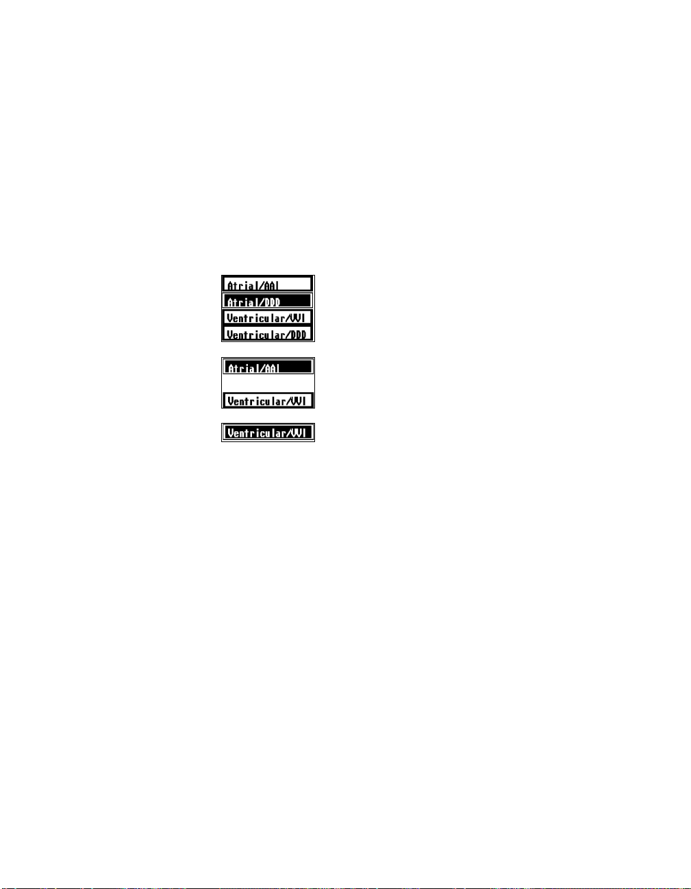
Determining and Evaluating Parameter Settings 7-3
Threshold Test Options
The first two steps in the procedure for conducting a threshold test are to
select a test chamber/mode option (when applicable) and to select the
desired threshold test type. The buttons for these options appear below the
waveform display on the Threshold Test Start screen.
Chamber/Mode Selection
The chamber/mode options that appear depend on the present permanent
pacing mode.
If the permanent pacing mode is DDD or DDDR, you
can choose to run the threshold test in the atrium or
the ventricle using either DDD or AAI/VVI as the
test mode.
If the permanent mode is a dual chamber mode other
than DDD or DDDR, you can choose the chamber,
but the test mode will be limited to AAI/VVI.
If the permanent mode is a single chamber mode, the
test chamber and mode will be fixed according to
chamber being paced.
Test Type Selection
Four test type buttons let you select one of three different threshold tests or
the Inhibit function.
AUTO AMPL THRESHOLD
[
tude threshold. Pressing and holding the [
ó Select this test to measure the patientís ampli-
]
PROGRAM
] button results in
automatic, step-by-step reduction of the pacing pulse amplitude.
AUTO PW THRESHOLD
[
width threshold. Pressing and holding the [
ó Select this test to measure the patientís pulse
]
PROGRAM
] button results in
automatic, step-by-step reduction of the pacing pulse width.
MANUAL THRESHOLD
[
ó Select this test to manually select and test specific
]
values for amplitude and pulse width. Automatic value reduction is not used
in this test. Only the selected values are tested while you press and hold the
PROGRAM
[
INHIBIT PACING
[
] button.
]
—
This button is available on the Threshold Test Start
screen as a convenience option. You can use it to temporarily inhibit output
of the pacemaker to view the patientís underlying rhythm or determine the
intrinsic rate. Use of this feature is described on page 5-9.
Page 94

7-4 Using the Programmer
Before You Begin the Test Procedure
Precautions
At any point during a threshold test, lifting the programming head from
over†the pacemaker for at least 2 seconds will return the pacemaker to its
permanently programmed state. This action should be taken in the event of
a†programmer malfunction, loss of power, or absence of an appropriate
command confirmation.
Be aware that movement of the programming head during an automatic
threshold test may interrupt communication between the programmer and
pacemaker, which will terminate the test.
A Note About Hysteresis
If Hysteresis has been programmed to ON during previous use of the AAI,
AAT, VVI, or VVT pacing mode, it will be in effect when ever you return
to one of these modes ó even temporarily such as during a threshold test.
If a message indicates that Hysteresis is in effect, you can program it to
OFF by returning to the Pacing Parameters screen. To access Hysteresis,
you must select one of the single chamber modes mentioned above.
Waveform Display
During setup and execution of a threshold test, the screen continuously
displays the patientís ECG and the telemetered waveforms being received
from the pacemaker. Adjust the ECG trace so that you easily can see pacing
artifacts and the resulting depolarization wave. During a threshold test, you
must be able to determine whether or not capture is maintained or lost as
pacemaker output is reduced, either manually or automatically.
Refer to Chapter 5, pages 5-6 to 5-8 for information about using and
adjusting the waveform display and about Marker telemetry.
Selecting Pulses Per Decrement
During a threshold test (except ìManual Thresholdî), the programmer
controls the number of pacing cycles it allows to occur at each threshold
test value before it automatically reduces the test value. As described in the
test procedures that follow, you can adjust the number of pacing cycles
(labeled ìPulses Per Decrementî) from 3 to 15 as desired.
A value should be chosen that allows adequate time to evaluate the patientís
ECG to determine whether or not capture is maintained or lost.
The programmer uses Marker telemetry to count pacing cycles during the
execution of a threshold test. If ìSensorî telemetry is programmed or Pace
markers are not otherwise being received, pacing cycles cannot be counted.
Page 95

Determining and Evaluating Parameter Settings 7-5
In such cases, the timing between automatic output reductions will default
to 8 seconds, and the selected number of pulses per decrement will not
apply.
NOTE: If the selected threshold test mode is DDD, the programmer will
count two Pace markers as one pacing cycle. If only one chamber is being
paced (pacing in the other chamber is inhibited), the number of pacing
cycles that occur between each test value reduction will be twice the number selected for Pulses Per Decrement.
NOTE: The time lapse between automatic test value reductions will not be
greater than 8 seconds, regardless of the selected number of pulses per
decrement.
Page 96

7-6 Using the Programmer
Conducting an Auto Amplitude or Auto Pulse
Width Threshold Test
Use this procedure to measure the patientís threshold using either amplitude
or pulse width. This procedure begins at the Threshold Test Start screen
(see page 7-2).
1. If the permanent pacing mode is a dual chamber mode, select the
desired ìchamber/modeî button ó [
Atrial/DDD
] for example.
2. Select the desired threshold test type: [
AUTO PW THRESHOLD
[
]. Execution of this step displays the test parame-
AUTO AMPL THRESHOLD
] or
ter setup options.
3. Use the [∧∧∧∧] and [∨∨∨∨] buttons to adjust each of the parameters to the
desired test value. The selected test values will be applied temporarily
during the threshold test.
Lower Rate —
Adjust to a value high enough to effect consistent
pacing. Loss of capture cannot be determined if the pacemaker is
inhibited.
Paced/Sensed AV —
If the test mode is DDD, adjust this interval to a
value short enough to provide a consistently paced ventricular rhythm.
The selected value applies to both Paced AV and Sensed AV intervals.
Pulse Width —
Adjust to the value you want in effect during the test.
If you are conducting an Auto PW test, this will be the starting test
value.
Amplitude —
Adjust to the value you want in effect during the test. If
you are conducting an Auto Ampl test, this will be the starting test
value.
Pulses Per Decrement
ó Adjust to the number of pacing cycles you
want to occur at each test value before reduction occurs (see page 7-4).
Page 97
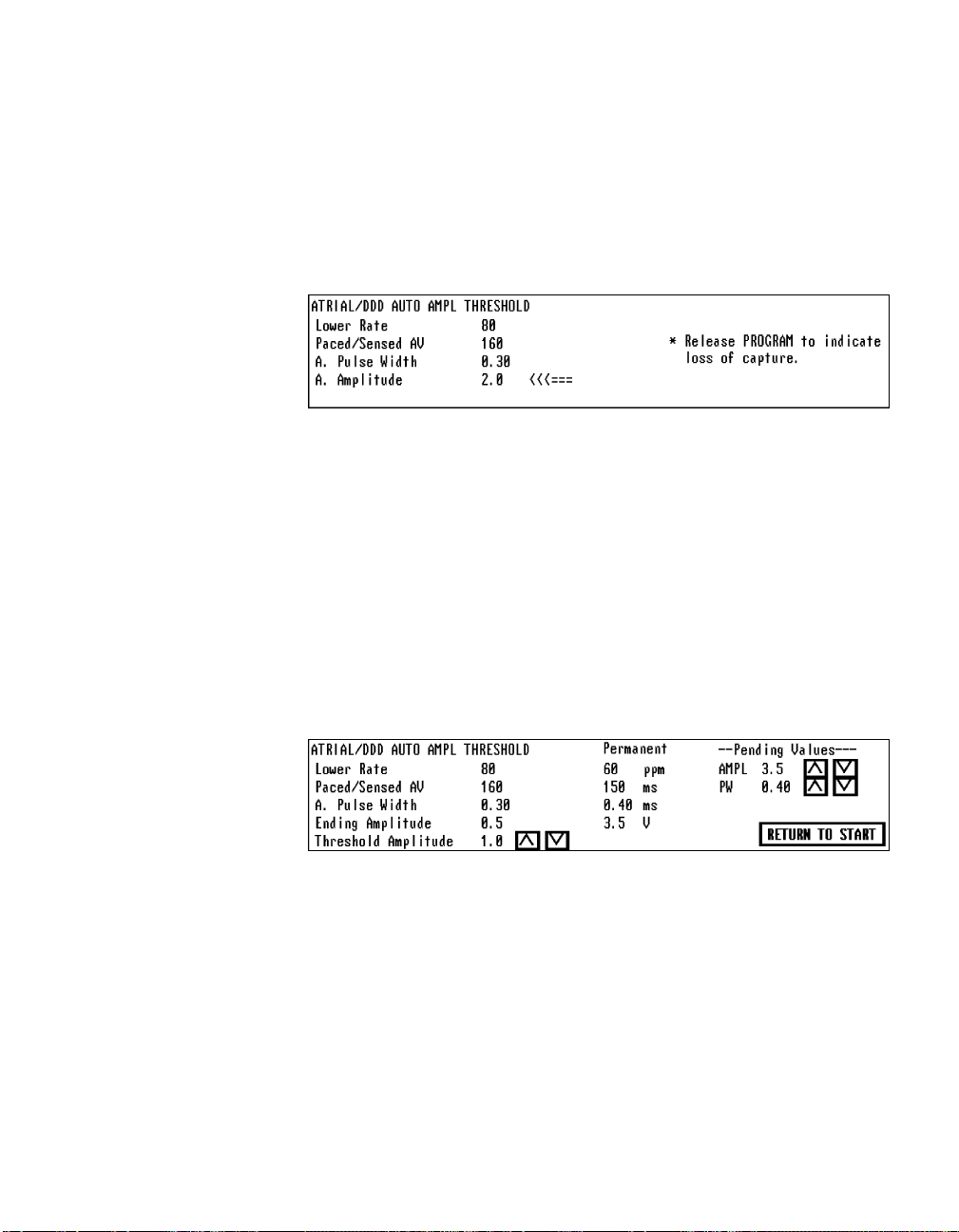
Determining and Evaluating Parameter Settings 7-7
4. Position the programming head and hold it steady in position for the
remainder of this procedure. Observe that Marker telemetry appears
below the ECG trace.
5. Press and hold [
PROGRAM] to execute the threshold test.
The threshold test execution window shows the temporary values in
effect. The arrow (
This example shows amplitude test execution. Pulse width test execution is similar.
<<<===
) points to the value being reduced.
Observe the patientís ECG trace as the programmer automatically
reduces the threshold test parameter one programmable step every 3 to
15 pacing cycles (as selected in step 3). An audible ìbeepî indicates
confirmation of each new test value.
6. When capture is lost, immediately release [
PROGRAM].
This action restores permanent parameter values and displays the
threshold value, which is one programmable step greater than the
ending test value.
If the ìEndingî test value is not the point at which capture was lost,
you can use the [∧∧∧∧] and [∨∨∨∨] buttons to adjust the displayed threshold
value.
This example shows the amplitude test results. Pulse width test results are similar.
The adjustable Pending values on the right side of the screen allow you
to directly program permanent settings for amplitude and pulse width.
The default values displayed are the present permanent settings.
7. To program permanent values for amplitude and pulse width, use the
[∧∧∧∧] and [∨∨∨∨] buttons to select a desired value for each parameter and
then press the [
PROGRAM] button. Do not lift the programming head
until confirmation is indicated.
To save the test results for printing, select [
RETURN TO START
] to return to
the Threshold Test Start screen, or select a menu button to exit this
function.
Page 98

7-8 Using the Programmer
Conducting a Manual Threshold Test
Use this procedure to determine the patientís threshold by manually testing
various parameter settings. This procedure begins at the Threshold Test
Start screen (see page 7-2).
1. If the permanent pacing mode is a dual chamber mode, select the
desired ìchamber/modeî button ó [
Atrial/DDD
] for example.
2. Select the [
MANUAL THRESHOLD
] test type button.
Execution of this step displays the test parameter setup options.
3. Use the [∧∧∧∧] and [∨∨∨∨] buttons to adjust each of the parameters to the
desired test value.
4. Position the programming head and hold it steady in position for the
remainder of this procedure.
5. To temporarily program the selected test values, press and hold the
PROGRAM
[
] button.
The test execution window shows the parameter settings now in effect.
Observe the patientís ECG to determine whether or not capture is
maintained.
6. To cancel the test values and restore permanent operation, release the
[
PROGRAM
] button.
This action returns you to the test parameter setup options. By using
this manual procedure to check incremental changes in the amplitude
or pulse width test value, you can determine the threshold value.
NOTE: Programmed test values are not saved for printing unless you
select the [
SAVE TEST VALUES
] button on the test parameter setup
screen. If you want to save a set of tested values, select this button after
you release the [
PROGRAM
] button.
Page 99

Determining and Evaluating Parameter Settings 7-9
7. To end the test and return to the Threshold Test Start screen, select
[
RETURN TO START], or select a menu button to exit the Threshold Test
function.
Printing the Threshold Test Results
During a patient session, the programmer can save the results of up to 32
threshold tests (8 pages of data). The results of ìautomaticî threshold test
are saved when you exit the test results screen. Results of a manual test
must be saved manually as described above.
To obtain a report of the threshold tests:
1. Select the [
2. Select
PRINT] menu button at the top of the screen.
THRESHOLD RESULTS from the listed options.
Maximum Number of Test Results Saved
If the maximum number of threshold test results that can be saved for
printing is reached during the patient session, any attempt to execute another threshold test will result in a pop-up window that prompts you to print
and then delete the currently saved test results. The window provides the
following options:
[
PRINT THRESHOLD VALUES] ó Selecting this button initiates a printout of
the stored threshold test values. This option lets you print the test values
before you delete them.
[
DELETE THRESHOLD VALUES
stored†threshold test results so that the programmer can save the results
of†subsequent threshold tests conducted during the patient session.
[
EXIT] ó Selecting this button closes the pop-up window. If you close the
window without deleting the stored threshold test results, the results of
subsequent threshold tests conducted during this patient session will not
be†saved for print out.
] ó Selecting this button deletes all the
Page 100

7-10 Using the Programmer
Programming Temporary Parameter Values
The Temporary Test function lets you evaluate different parameter settings
or use high-rate pacing while having the option to quickly and easily return
to the original permanent settings. The test settings remain in effect only
while the [
PROGRAM
] button is pressed and held. Releasing [
returns the pacemaker to its permanently programmed state.
Selecting the Temporary Test Screen
PROGRAM
]
1. Select
2. Select
TESTS/ECG
[
menu button.
TEMPORARY
TEST
option.
]
Temporary Test
Screen
Refer to pages 5-6 and
5-7 for instructions on
adjusting the ECG and
telemetry traces.
To display the Temporary Test screen, select the [
and then select the
TEMPORARY TEST
option as illustrated below.
TESTS/ECG
] menu button,
If an appropriate interrogation has not occurred, a screen message will
direct you to interrogate the pacemaker to display the Temporary Test
screen. In this example, Marker and EGM telemetry are being received.
 Loading...