

Page 1

TRANSVENE® -CS/SVC 6937A
Unipolar, endocardial, CS/SVC lead
Technical manual
Caution: Federal law (USA) restricts this
device to sale by or on the order of a
physician.
Page 2

Page 3

Table of contents
Device description 1
Contents of package 1
Accessory descriptions 1
Indications for use 1
Contraindications 2
Warnings and precautions 2
Adverse events 4
Observed adverse events 4
Potential adverse events 5
Clinical studies 5
Directions for use 7
Opening the sterile package 7
Inserting the lead 7
Positioning the lead in the superior vena cava 9
Positioning the lead in the coronary sinus 9
Taking defibrillation efficacy measurements 10
Anchoring the lead 11
Connecting the lead 12
Placing the device and lead into the pocket 12
Post-implant evaluation 13
Detailed device description 14
Specifications (nominal) 14
Specifications drawings (nominal) 15
Special notice 16
Service 16
6937A Technical manual iii
Page 4

Page 5

Device description
The Medtronic Transvene-CS/SVC Model 6937A Unipolar,
endocardial lead is designed for delivering cardioversion and
defibrillation therapies in either the coronary sinus or superior vena
cava. Silicone insulation with a polyurethane overlay surrounds the
low resistance conductor coil and the coil electrode is a platinum alloy.
The lead has a DF-1
section "Detailed device description."
Contents of package
The lead and accessories are provided sterile. Each package
contains the following:
■
One lead with one2 radiopaque anchoring sleeve, stylet, and
stylet guide
■
One vein lifter
■
Extra stylets
■
Product literature
Accessory descriptions
Stylets – A stylet provides additional stiffness and controlled
flexibility for maneuvering the lead into position. Each stylet knob is
labeled with the stylet diameter and length. Curving the stylet prior to
insertion into the lead will achieve a curvature at the lead’s distal end.
Stylet guide – A stylet guide facilitates stylet insertion into the lead.
A notch in the stylet guide allows connection of a surgical cable for
electrical measurements.
Anchoring sleeves – An anchoring sleeve secures the lead from
moving and protects the lead insulation and conductors from damage
caused by tight ligatures. An anchoring sleeve is radiopaque for
visualization on standard X-ray equipment.
Vein lifter – A vein lifter facilitates lead insertion into a vessel.
1
connector. For further information, refer to the
Indications for use
The lead is intended for single long-term use in the coronary sinus
or superior vena cava for delivering atrial cardioversion and
defibrillation therapies.
The lead has application for patients in which implantable
cardioverter defibrillators are indicated.
1
DF-1 refers to the International Connector Standard (ISO 11318) whereby
pulse generators and leads so designated are assured of a basic
mechanical fit.
2
Two anchoring sleeves are provided with leads of 85 cm or longer.
6937A Technical manual 1
Page 6

Note: Prior to lead implant, it is strongly recommended that patients
undergo a complete cardiac evaluation, which should include
extensive electrophysiologic testing. Also, extensive
electrophysiologic evaluation and testing of the safety and efficacy of
the proposed pacing, cardioversion, or defibrillation therapies are
recommended during and after the implantation of the system.
Contraindications
Arrhythmia types – The lead is contraindicated for patients with any
of the following conditions:
■
Transient ventricular tachyarrhythmias due to reversible
causes, such as drug intoxication, electrolyte imbalance,
sepsis, or hypoxia.
■
Transient ventricular tachyarrhythmias due to other factors,
such as myocardial infarction and electrocution.
Warnings and precautions
Inspecting the sterile package – Carefully inspect the package
prior to opening:
■
If the seal or package is damaged, contact your local
Medtronic representative.
■
Do not use the product after its expiration date.
■
The lead has been sterilized with ethylene oxide prior to
shipment. If the integrity of the sterile package has been
compromised prior to the expiration date, resterilize using
ethylene oxide.
Ethylene oxide resterilization – If the sterile package seal is
broken, resterilize the device using a validated ethylene oxide
process. Avoid resterilization techniques that could damage the lead:
■
Refer to sterilizer instructions for operating instructions.
■
Use an acceptable method for determining sterilizer
effectiveness, such as biological indicators.
■
Before resterilization, place the device in an ethylene oxide
permeable package.
■
Do not exceed temperatures of 55°C (130°F).
■
Do not resterilize more than one time.
■
After resterilization, allow the device to aerate ethylene
oxide residues.
2 6937A Technical manual
Page 7

Handling the lead – Leads should be handled with great care at
all times:
■
Protect the lead from materials shedding particles such as lint
and dust. Lead insulators attract these particles.
■
Handle the lead with sterile surgical gloves that have been
rinsed in sterile water or a comparable substance.
■
Do not severely bend, kink, or stretch the lead.
■
Do not use surgical instruments to grasp the lead or
connector pins.
■
Do not immerse leads in mineral oil, silicone oil, or any other
liquid, except blood at the time of implantation.
■
Inserting the lead using a lead introducer that features a
hemostasis valve may require a larger introducer than the size
recommended. Do not withdraw the lead through a hemostasis
valve, to avoid distortion of the coil electrode.
Handling the stylets – Use care when handling stylets:
■
Do not use excessive force or surgical instruments when
inserting a stylet.
■
Avoid overbending, kinking, or blood contact.
■
Use a new stylet when blood or other fluids accumulate on the
stylet. Repeated insertions of a stylet increases the probability
that blood or other fluids may accumulate on the stylet, which
may cause difficulty in passing the stylet through the lead or
damage to the lead.
■
Do not use a sharp object to impart a curve to the distal end of
the stylet, to avoid damage to the stylet.
Necessary hospital equipment – Keep external defibrillation
equipment nearby for immediate use during the acute lead system
testing, implantation procedure, or whenever arrhythmias are
possible or intentionally induced during post-implant testing.
Line-powered equipment – An implanted lead forms a direct
current path to the myocardium. During lead implantation and testing,
use only battery-powered equipment or line-powered equipment
specifically designed for this purpose, to protect against fibrillation
that may be caused by alternating currents. Line-powered equipment
used in the vicinity of the patient must be properly grounded. Lead
connector pins must be insulated from any leakage currents that may
arise from line-powered equipment.
Second anchoring sleeve – For leads 85 cm or longer, which
feature two anchoring sleeves, use both anchoring sleeves as
described in the “Anchoring the lead” section, to assure
adequate fixation.
Chronic repositioning or removal – Chronic repositioning or
removal of leads may be difficult because of fibrotic tissue
development. Return all removed or unused leads to Medtronic. If a
lead must be removed or repositioned, proceed with extreme caution:
6937A Technical manual 3
Page 8

■
Removal of the lead may result in avulsion of the endocardium,
valve, or vein.
■
If a lead is abandoned, it should be capped to avoid transmitting
electrical signals.
■
A lead that has been cut off should have the remaining lead end
sealed, and the lead should be sutured to adjacent tissue to
avoid migration into the heart.
Connector compatibility – Although the lead conforms to the
International Connector Standard DF-1, do not attempt to use the
Model 6937A lead with any device other than a commercially
available implantable defibrillator system with which it has been
tested and demonstrated to be safe and effective. The potential
adverse consequences of using such a combination may include, but
are not limited to, undersensing cardiac activity and failure to deliver
necessary therapy.
Adverse events
Observed adverse events
The Transvene-CS/SVC Model 6937A Unipolar, endocardial, CS/
SVC lead was utilized in the SVC and coronary sinus during the
Model 7250 Jewel
patients who received a Model 7250 AF Implantable Cardioverter
Defibrillator received a Model 6937A lead in either the coronary sinus
or the SVC. Individual patient implant time averaged 12.8 months,
with a range of 0.1 to 24.7 months.
Eight patient deaths occurred in this group of patients. All deaths
were reviewed and judged to be non-system related by an
independent advisory committee. The deaths were attributed to:
congestive heart failure (3), ischemic cardiomyopathy (1),
cardiomyopathy (1), hypoxic encephalopathy (1), lung cancer (1) and
cardiogenic shock/respiratory failure (1).
Lead-related complications and lead-related observations are
summarized in Table 1:
Tab le 1 . Lead-related complications and observationsa all patients (N = 114)
Complications
Lead dislodgment 3 3
To t al 3 3
Observations
Subclavian vein thrombosis 1 1
To t a l 1 1
a
database closure: 5/31/2000
AF clinical study. One hundred fourteen of 676
# of events # of patients
4 6937A Technical manual
Page 9

Potential adverse events
The potential adverse events related to the use of endocardial leads
include, but are not limited to, the following patient-related conditions:
■
Cardiac perforation
■
Cardiac tamponade
■
Constrictive pericarditis
■
Coronary sinus perforation
■
Embolism
■
Endocarditis
■
Fibrillation or other arrhythmias
■
Heart wall rupture
■
Hemothorax
■
Infection
■
Pneumothorax
■
Thrombosis
■
Tissue necrosis
Other potential adverse events related to the lead include, but are not
limited to, the following:
■
Insulation failure
■
Lead conductor or electrode fracture
■
Lead dislodgement
■
Poor connection to the device, which may lead to oversensing,
undersensing, or a loss of therapy.
Clinical studies
Model 6937A data was derived from two clinical investigations of the
Model 7250 Jewel AF device. One of the clinical investigations
focused on patients with VT/AT indications and the other investigation
focused on patients with AF indications. The clinical investigations
were conducted in the U.S., Europe, and Canada. These studies
were conducted primarily to verify that the atrial prevention and
treatment therapies of the Model 7250 Jewel AF were safe and
effective as evaluated in their respective patient populations.
In the VT/AT clinical investigation, the Model 6937A lead was utilized
in 35 of 530 patients receiving a Model 7250 Jewel AF device. VT/AT
patients had to meet the following eligibility criteria: 1) at least one
episode of cardiac arrest due to ventricular tachyarrhythmia not
caused by an acute myocardial infarction; or recurrent, sustained VT
(spontaneous or inducible), and 2) at least two documented episodes
of some form of atrial tachyarrhythmia occurring in the last year, with
at least one episode documented on ECG.
In the AF-only clinical investigation, the Model 6937A lead was
utilized in 79 of 146 patients receiving a Model 7250 Jewel AF device.
AF-only patients had to meet the following eligibility criteria: 1) at least
two episodes of symptomatic, drug refractory atrial fibrillation or atrial
flutter occurring in the last three months, with at least one episode
documented on ECG.
6937A Technical manual 5
Page 10

Patients studied – Patient demographics for both studies are listed
in Table 2.
Table 2. Patient demographics
Patient characteristic VT/AT (N=35) AF-only (N=79) P-Value
Gender (N,%)
Male 30 (85.7%) 58 (73.4%) 0.230
Female 5 (14.3%) 21 (26.6%)
Age (years)
Mean 67.4 64.3 0.157
Range 31.2 - 84.5 38.1 - 82.0
Standard deviation 11.4 10.7
Spontaneous ventricular
arrhythmia history
(non-exclusive, N,%)
Sustained VT 21 (60.0%) 1 (1.3%) <0.001
Nonsustained VT 11 (31.4%) 5 (6.3%) 0.001
Ventricular flutter 1 (2.9%) 0 0.674
Ventricular fibrillation 8 (22.9%) 2 (2.5%) 0.001
Spontaneous atrial
arrhythmia history
(non-exclusive, N,%)
Atrial fibrillation 31 (88.6%) 77 (97.5%) 0.132
Atrial flutter 5 (14.3%) 19 (24.1%) 0.352
Methods - For both studies, clinical data was collected at pre-implant
assessment/enrollment, implant, scheduled and unscheduled followup visits; and for system modifications and patient deaths. Scheduled
follow-up visits were required at one, three, and six months postimplant, with continued follow-ups every six months afterwards.
Atrial defibrillation thresholds (A-DFTs) were determined by using a
two-tiered step-up protocol.
Results – The A-DFT results for both studies are provided in Table 3.
.
A-DFT at implant VT/AT
Mean A-DFT (J) 3.8 6.6 6.2
Range 2 - 6 2 -18 2 - 18
Standard deviation 1.8 4.8 4.6
Tab le 3 . A-DFTs at implant
(N=10)
AF-only
(N=53)
Combined
(N=63)
Conclusion – The clinical experience with the Model 6937A CS/SVC
lead demonstrates that the lead is safe and effective for human use.
6 6937A Technical manual
Page 11

Directions for use
Proper surgical procedures and sterile techniques are the
responsibility of the medical professional. The implant procedures
described in this manual are furnished for information only. Each
physician must apply the information in these instructions according
to professional medical training and experience.
The implantation procedure generally includes the following steps:
■
Opening the sterile package
■
Inserting the lead
■
Positioning the lead in the superior vena cava or coronary sinus
■
Taking defibrillation efficacy measurements
■
Anchoring the lead
■
Connecting the lead
■
Placing the device and lead into the pocket
Opening the sterile package
Open the sterile package and inspect the lead:
1. Within the sterile field, open the sterile package and remove the
lead and accessories.
2. Inspect the lead. Leads shorter than 85 cm should have one
anchoring sleeve. Leads 85 cm or longer should have two
anchoring sleeves.
Inserting the lead
Caution: Use care when handling the lead during insertion:
■
Do not severely bend, kink, or stretch the lead.
■
Do not use surgical instruments to grasp the lead or
connector pins.
Insert the lead using the techniques described below:
1. Select a site for lead insertion. The lead may be inserted by
venotomy through several different venous routes, including the
right or left cephalic vein or the external or internal jugular vein.
The lead may also be inserted through the subclavian vein by
using a percutaneous lead introducer kit. Use the cephalic vein
whenever possible to avoid lead damage in the first rib/
clavicular (thoracic inlet) space.
Certain anatomical abnormalities, such as thoracic outlet
syndrome, may also precipitate pinching and subsequent
fracture of the lead.
6937A Technical manual 7
Page 12
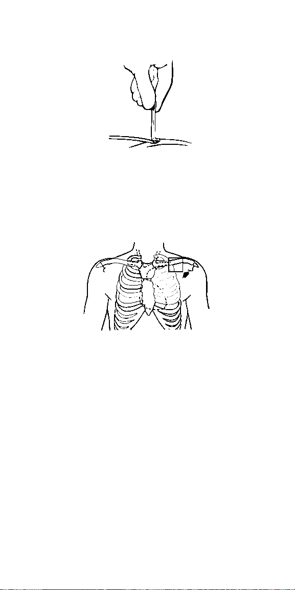
2. If using a cephalic approach, insert the tapered end of a vein
lifter into the incised vein and gently push the lead tip
underneath and into the vein (Figure 1).
Figure 1.
Caution: If the subclavian approach is required, avoid techniques
that may damage the lead:
■
Insertion via a subclavian approach should be done as far
lateral as possible to avoid clamping the lead body between
the clavicle and the first rib (Figure 2). Clamping the lead
may cause lead damage which may result in the loss
of therapy.
Figure 2.
■
Do not force the lead if significant resistance is encountered
during lead passage.
■
Do not use techniques such as adjusting the patient’s
posture (e.g., raising the arm or putting a towel behind the
back) to facilitate lead passage. If resistance is
encountered, it is recommended that an alternate venous
entry site be used, such as the cephalic vein.
3. Advance the lead into the right atrium or the superior vena cava
using a straight stylet to facilitate movement through the veins.
8 6937A Technical manual
Page 13

Positioning the lead in the superior vena cava
Caution: Use care when handling the lead during positioning.
■
Do not severely bend, kink, or stretch the lead.
■
Do not use surgical instruments to grasp the lead or
connector pins.
Position the lead in the superior vena cava using the technique
described below.
1. With a straight stylet inserted in the lead, advance the lead into
the superior vena cava.
Note: If the distal end of the lead tip enters the right atrium, the
lead has been advanced too far. Reposition the lead.
Use fluoroscopy to ensure that the distal end of the coil
electrode is properly positioned in the superior vena cava.
Proper positioning of the coil electrode is essential for
defibrillation efficacy.
Positioning the lead in the coronary sinus
Caution: Use care when handling the lead during positioning.
■
Do not severely bend, kink, or stretch the lead.
■
Do not use surgical instruments to grasp the lead or
connector pins.
Position the lead in the coronary sinus using the technique
described below:
1. Bend the stylet into a gentle curve. Imparting a curve to the
stylet can be accomplished with a smooth-surface, sterile
instrument as shown (Figure 3).
Caution: Do not use a sharp object to impart a curve to the
distal end of the stylet, to avoid damage to the stylet.
Figure 3.
2. Advance the lead into the right atrium and rotate the curved
stylet to manipulate the lead tip over the tricuspid valve. Move
the lead tip medially and posteriorly to the coronary sinus
ostium. Keep the stylet tip inserted just inside the coronary
sinus ostium and advance the lead off of the stylet into the
coronary sinus.
6937A Technical manual 9
Page 14

Note: If the lead goes through the tricuspid valve opening,
retract the lead with a gentle posterior rotation and then
advance it toward the coronary ostium.
3. Position the coil electrode so that it is entirely within the
coronary sinus. Push the lead to a position as distal as possible
in the coronary sinus.
Use fluoroscopy (P-A and lateral position) to ensure the coil
electrode is properly positioned in the coronary sinus. Proper
positioning of the coil electrode is essential for
defibrillation efficacy.
Taking defibrillation efficacy measurements
Caution: Prior to taking defibrillation efficacy measurements, move
objects made of conductive materials, such as guidewires, away from
all electrodes. Metal objects, such as guidewires, can short a lead
and active implantable device, causing electrical current to bypass
the heart and possibly damage the implantable device and lead.
Ventricular defibrillation efficacy measurements –
Establish ventricular defibrillation efficacy using the technique
described below:
1. Make sure the lead is in the desired position.
2. Remove the stylet from the lead.
3. Connect the lead to the device.
4. Put the device in the subcutaneous pocket.
5. Establish ventricular defibrillation efficacy with at least a 10 J
safety margin.
In order to keep patient morbidity and mortality to a minimum,
patients should be rescued promptly with an external
defibrillator if the implanted lead system fails to terminate a
VF episode. At least five minutes should elapse between
VF inductions.
6. After establishing defibrillation efficacy, anchor the lead.
Atrial defibrillation efficacy measurements – After establishing
ventricular defibrillation efficacy, atrial defibrillation efficacy
measurements may be obtained using the technique
described below:
1. Make sure the leads are in the desired position.
2. Remove the stylet from the lead.
3. Connect the lead to the device if this has not already been done
while taking ventricular defibrillation efficacy measurements.
4. Put the device in the subcutaneous pocket if this has not
already been done while taking ventricular defibrillation
efficacy measurements.
5. Establish atrial defibrillation efficacy.
6. If the leads have not already been anchored, anchor the leads.
10 6937A Technical manual
Page 15

Anchoring the lead
Caution: Use care when anchoring the lead:
■
Use only nonabsorbable sutures to anchor the lead.
■
Do not attempt to remove or cut the anchoring sleeve. This may
cause damage to the lead insulation.
■
During anchoring, take care to avoid dislodging the lead.
■
Do not secure ligatures so tightly that they damage the vein,
lead, or anchoring sleeve.
■
Do not tie a ligature directly to the lead body (Figure 4).
Figure 4.
Anchor the lead using all three grooves:
1. Position the anchoring sleeve against or near the vein.
2. Secure the anchoring sleeve to the lead body by tying a suture
firmly in each of the three grooves (Figure 5). Suturing in the
triple grooves is the only recommended location for the sutures.
Figure 5.
3. After securing the anchoring sleeve to the lead body, use at
least one additional suture in one of the grooves to secure the
anchoring sleeve and lead body to the fascia.
4. A second anchoring sleeve is provided with leads 85 cm or
longer. For abdominal implants, redundant lead body (e.g., a
curve for strain relief) should be placed just proximal to the first
anchoring sleeve, then the second anchoring sleeve may be
lightly sutured to the lead body and fascia to hold the curve in
place. This procedure helps isolate the vein entry site from
tension on the proximal end of the lead body.
6937A Technical manual 11
Page 16

Connecting the lead
Note: If tunneling the lead, record each lead’s serial number along
with the function of the lead before tunneling.
Use the following techniques to connect the lead to an
implantable device:
1. If tunneling the lead connectors to the implantable device is
required, use a chest tube to prevent damage to the lead.
Tunnel the lead subcutaneously to the device pocket.
Caution: Do not use surgical instruments to grasp the lead or
connector pins when tunneling.
2. Insert the lead connectors into the connector block. Consult the
manual packaged with the implantable device for instructions
on proper lead connections.
Caution: Always remove the stylet before connecting the lead
to the implantable device. Failure to remove the stylet may
result in lead failure.
3. Before closing the pocket, verify cardioversion, and
defibrillation efficacy.
Placing the device and lead into the pocket
Caution: Use care when placing the device and lead into the pocket:
■
Ensure that the lead does not leave the device at an acute
angle. A sharp angle or excessive pressure places undue
stress on the lead conductor and insulation.
■
Do not grip the lead or device with surgical instruments.
■
Do not coil the lead. Coiling the lead can twist the lead body and
may result in lead dislodgment (Figure 6).
Figure 6.
12 6937A Technical manual
Page 17

Use the following techniques to place the implantable device and lead
into the pocket:
1. To prevent undesirable twisting of the lead body, rotate the
device to loosely wrap the excess lead length (Figure 7).
Figure 7.
Place the device and lead into the pocket.
Post-implant evaluation
After implantation, monitor the patient’s electrocardiogram
continuously. If a lead dislodges, it usually occurs during the
immediate postoperative period.
The patient should have X-rays taken at pre-hospital discharge, three
months after implant, and every six months thereafter to verify proper
lead position and to check for conductor fractures.
In the event of a patient death, all implanted leads and devices should
be explanted and returned to Medtronic with a completed Product
Information Report. Any questions on product handling procedures
can be addressed by calling the appropriate number on the
back cover.
6937A Technical manual 13
Page 18

Detailed device description
Specifications (nominal)
Parameter Model 6937A
Type Unipolar
Position CS or SVC
Fixation None
Length 20-110 cm
Connector DF-1
Materials Conductor:
Diameters Lead body:
Conductor resistances Defibrillation: 1.5 Ω (max) at 58 cm
Lead introducer
(recommended size)
Insulator:
Outer layer:
Coil electrode:
Coil electrode:
without guide wire:
with guide wire:
Multifilar MP35N composite
Silicone
Polyurethane tubing
Platinum alloy
2.5 mm
2.3 mm
9 French
10.5 French
14 6937A Technical manual
Page 19

Specifications drawings (nominal)
Coil electrode
Surface area: 125 mm
Electrical shadow area: 355 mm
Length: 50 mm
Anchoring sleeve
Note: Leads 85 cm or
longer feature a second
anchoring sleeve
2
2
DF-1 connector
Note: Connector pin is
common to coil electrode
6937A Technical manual 15
Page 20

Special notice
Medtronic implantable leads are implanted in the extremely hostile
environment of the human body. Leads are necessarily very small in
diameter and must still be very flexible, which unavoidably reduces
their potential performance or longevity. Leads may fail to function for
a variety of causes, including, but not limited to: medical
complications, body rejection phenomena, allergic reaction, fibrotic
tissue, or failure of leads by breakage or by breach of their insulation
covering. In addition, despite the exercise of all due care in design,
component selection, manufacture, and testing prior to sale, leads
may be easily damaged before, during, or after insertion by improper
handling or other intervening acts. Consequently, no representation
or warranty is made that failure or cessation of function of leads will
not occur or that the body will not react adversely to the implantation
of leads or that medical complications (including perforation of the
heart) will not follow the implantation of leads or that the lead will, in
all cases, restore adequate cardiac function.
For complete warranty information, see the accompanying card
enclosed in the package.
Service
Medtronic employs highly trained representatives and engineers
located throughout the world to serve you and, upon request, to
provide training to qualified hospital personnel in the use of Medtronic
products. Medtronic also maintains a professional staff to provide
technical consultation to product users. For medical consultation,
Medtronic can often refer product users to outside medical
consultants with appropriate expertise. For more information, contact
your local Medtronic representative, or call or write Medtronic at the
appropriate address or telephone number listed on the back cover.
16 6937A Technical manual
Page 21

Page 22

Page 23

Page 24

Europe
Europe/Africa/Middle East
Headquarters
Medtronic Europe S.A.
Route du Molliau
1131 Tolochenaz
Switzerland
Internet: www.medtronic.co.uk
Tel. 41-21-802-7000
Fax 41-21-802-7900
Medtronic E.C. Authorized
Representative
Medtronic B.V.
Wenckebachstraat 10
6466 NC Kerkrade
The Netherlands
Tel. 31-45-566-8000
Fax 31-45-566-8668
Asia-Pacific
Japan
Medtronic Japan
Solid Square West Tower 6F,
580 Horikawa-cho, Saiwai-ku,
Kawasaki, Kanagawa 210-0913
Japan
Tel. 81-44-540-6112
Fax 81-44-540-6200
Australi a
Medtronic Australasia Pty. Ltd.
Unit 4/446 Victoria Road
Gladesville NSW 2111
Australia
Tel. 61-2-9879-5999
Fax 61-2-9879-5100
Asia
Medtronic International Ltd.
Suite 1602 1 6/F, Manulife Plaz a
The Lee Gardens,
33 Hysan Avenue
Causeway Bay
Hong Kong
Tel. 852-2891-4068
Fax 852-2591-0313
Americas
Latin America Headquarters
Medtronic, Inc.
710 Medtronic Parkway NE
Minneapolis, MN 55432-5604
USA
Tel. 763-514-4000
Fax 763-514-4879
Canada
Medtronic of Canada Ltd.
6733 Kitimat Road
Mississauga, Ontario L5N 1W3
Tel. 905-826-6020
Fax 905-826-6620
Toll-free in Canada:
1-800-268-5346
United States
World Headquarters
Medtronic, Inc.
710 Medtronic Parkway NE
Minneapolis, MN 55432-5604
USA
Internet: www.medtronic.com
Tel. 763-514-4000
Fax 763-514-4879
Medtronic USA, Inc.
Toll-free in the USA:
1-800-723-4636
(24-hour consultation
for physicians and
medical professionals)
*197885001*
© Medtronic, Inc. 2001
All Rights Reserved
UCX197885001 197885001
April 2001
 Loading...