

Page 1
SPRINT QUATTRO SECURE S MRI™ SURESCAN™ 6935M
MR Conditional, steroid-eluting, tripolar, screw-in, ventricular lead with RV defibrillation coil electrode
Technical Manual
Caution: Federal law (USA) restricts this device to sale by or on the order of a physician.
Page 2

The following list includes trademarks or registered trademarks of Medtronic in the United States and possibly in other countries. All other trademarks
are the property of their respective owners.
AccuRead, Evera, Evera MRI, Medtronic, Sprint Quattro, Sprint Quattro Secure, Sprint Quattro Secure S, Sprint Quattro Secure S MRI, SureScan,
Tensi-Lock
Page 3

Contents
1 Description 3
2 Drug component description 4
3 Indications 4
4 Contraindications 4
5 Warnings and precautions 4
6 Adverse events and clinical trial data 6
7 Drug information 6
8 Directions for use 7
9 Specifications (nominal) 13
10 Medtronic disclaimer of warranty 15
11 Service 15
12 Explanation of symbols on package labeling 15
1 Description
The Medtronic Sprint Quattro Secure S MRI SureScan Model
6935M lead is a steroid-eluting, tripolar, screw-in, ventricular lead
with a right ventricular (RV) defibrillation coil electrode. The lead is
designed for pacing, sensing, cardioversion, and defibrillation
therapies. The following lead lengths are MR conditional: 55 cm
and 62 cm. Other lead lengths are not MR conditional.
The lead features an extendable and retractable helix electrode,
silicone insulation, and parallel conductors. The 3 electrodes of
the lead are the helix, ring, and RV coil. The lead also features
Tensi-Lock1 and silicone-backfilled defibrillation coils.
The Medtronic DF4-LLHO2 four-pole HV inline connector on the
lead facilitates device connection during implant. The DF4
connector pin has a color band indicator that may be used to
visually confirm proper connection to the device.
The RV coil delivers cardioversion and defibrillation therapies.
Pacing and sensing occur between the helix and either the ring or
RV coil electrode. An AccuRead analyzer cable interface tool (ACI
tool) is attached to the lead to facilitate accurate electrical
measurements during implant.
The helix electrode can be actively fixed into the endocardium.
The helix electrode can be extended or retracted by rotating the
DF4 connector pin with the purple fixation tool included in the
package.
The distal tip contains a nominal dosage of 685 µg of
dexamethasone acetate and 59 µg of dexamethasone sodium
phosphate. Upon exposure to body fluids, the steroids elute from
the lead tip. The steroids are known to suppress the inflammatory
response that is believed to cause threshold rises typically
associated with implanted pacing electrodes.
1.1 Medtronic SureScan defibrillation system
A complete SureScan defibrillation system is required for
use in the MR environment. A complete SureScan
defibrillation system includes a Medtronic SureScan device
with the appropriate number of Medtronic SureScan leads.
The Model 6935M lead is part of the Medtronic SureScan
defibrillation system. Labeling for SureScan defibrillation system
components displays the MR Conditional symbol. To verify that
components are part of a SureScan system, visit
http://www.mrisurescan.com. Any other combination may result
in a hazard to the patient during an MRI scan.
The MRI SureScan feature permits a mode of operation that
allows a patient with a SureScan system to be safely scanned by
an MRI machine while the device continues to provide appropriate
pacing. When programmed to On, MRI SureScan operation
disables arrhythmia detection and all user-defined diagnostics.
Before performing an MRI scan, refer to the MRI Technical
Manual.
1.2 Package contents
Leads and accessories are supplied sterile. Each package
contains the following items:
●
1 lead with a radiopaque anchoring sleeve, stylet, and ACI tool
●
2 purple fixation tools
●
1 purple stylet guide
●
1 slit anchoring sleeve
●
1 vein lifter
●
extra stylets
●
product literature
1.3 Accessory descriptions
Dispose of all single-use accessories according to local
environmental requirements.
AccuRead analyzer cable interface (ACI) tool – The ACI tool
facilitates accurate electrical measurements during implant and
prevents possible connector damage.
Anchoring sleeve – An anchoring sleeve secures the lead to
prevent it from moving and protects the lead insulation and
conductors from damage caused by tight sutures.
Purple fixation tool – The purple fixation tool facilitates
connector pin rotation.
Purple stylet guide – A stylet guide facilitates stylet insertion into
the lead.
Slit anchoring sleeve – A slit anchoring sleeve secures excess
lead length in the device pocket.
1
Tensi-Lock is an exclusive Medtronic design feature that utilizes lead body cables to act like a built-in locking stylet and add tensile strength to the lead.
2
DF4-LLHO refers to the international standard ISO 27186:2010, where the lead connector contacts are defined as low voltage (L), high voltage (H), or open (O).
3
Page 4

Stylet – A stylet provides additional stiffness and controlled
flexibility for maneuvering the lead into position. Each stylet knob
is labeled with the stylet diameter and corresponding lead length.
Vein lifter – A vein lifter facilitates lead insertion into a vein.
2 Drug component description
The active ingredients in the Model 6935M lead are
dexamethasone acetate [21-(acetyloxy)-9-fluoro-11β,
17-trihydroxy-16α-methylpregna-1,4-diene-3,20-dione] and
dexamethasone sodium phosphate [9-fluoro-11β,
17-dihydroxy-16α-methyl-21-(phosphonooxy)
pregna-1,4-diene-3,20-diene-3,20-dione disodium salt]. The
structural formula for these steroids is shown in the following
figures.
Dexamethasone acetate is a white to practically white, odorless
powder. It is a practically insoluble ester of dexamethasone, a
synthetic adrenocortical steroid.
Figure 1. Structural formula for dexamethasone acetate (DXAC)
C24H31FO
Dexamethasone sodium phosphate is an inorganic ester of
dexamethasone, a synthetic adrenocortical steroid.
Dexamethasone sodium phosphate is a white or slightly yellow
crystalline powder. It is freely soluble in water and is very
hygroscopic.
Figure 2. Structural formula for dexamethasone sodium
phosphate (DSP) C22H28FNa2O8P
The maximum dosage of dexamethasone acetate and
dexamethasone sodium phosphate is less than 1.0 mg per lead.
6
3 Indications
The lead is intended for single, long-term use in the right ventricle.
This lead has application for patients for whom implantable
cardioverter defibrillators (ICDs) are indicated.
4 Contraindications
Atrial use – The lead is contraindicated for the sole use of
detection and treatment of atrial arrhythmias.
Ventricular use – The lead is contraindicated for ventricular use
in patients with tricuspid valvular disease or a tricuspid
mechanical heart valve.
Transient ventricular tachyarrhythmias – The lead is
contraindicated for patients with transient ventricular
tachyarrhythmias due to reversible causes (drug intoxication,
electrolyte imbalance, sepsis, hypoxia) or other factors
(myocardial infarction, electric shock).
Steroid use – The lead is contraindicated in patients for whom a
single dose of 1.0 mg of dexamethasone acetate and
dexamethasone sodium phosphate may be contraindicated.
5 Warnings and precautions
A complete SureScan defibrillation system is required for
use in the MR environment. Before performing an MRI scan,
refer to the MRI Technical Manual for MRI-specific warnings
and precautions.
Inspecting the sterile package – Inspect the sterile package
before opening it.
●
If the seal of the package is damaged, contact a Medtronic
representative.
●
Do not store this product above 40 °C (104 °F).
●
Do not use the product after its expiration date.
Single use – The lead and accessories are for single use only.
Sterilization – Medtronic has sterilized the package contents
with ethylene oxide before shipment. This lead is for single use
only and is not intended to be resterilized.
Connector compatibility – Although the lead conforms to the
International Connector Standard for DF4, do not attempt to use
the lead with any device other than a commercially available
implantable defibrillator system with which it has been tested and
demonstrated to be safe and effective. The potential adverse
consequences of using such a combination may include, but are
not limited to, undersensing cardiac activity and failure to deliver
necessary therapy.
Electrophysiologic testing – Prior to lead implant, it is strongly
recommended that patients undergo a complete cardiac
evaluation, which should include electrophysiologic testing. Also,
electrophysiologic evaluation and testing of the safety and
efficacy of the proposed pacing, cardioversion, or defibrillation
4
Page 5

therapies are recommended during and after the implant of the
system.
Steroid use – It has not been determined whether the warnings,
precautions, or complications usually associated with injectable
dexamethasone sodium phosphate or dexamethasone acetate
apply to the use of this highly localized, controlled-release device.
For a list of potential adverse effects, refer to the Physicians’ Desk
Reference.
Handling the steroid tip – Avoid reducing the amount of steroid
available before implanting the lead. Reducing the available
amount of steroid may adversely affect low-threshold
performance.
●
Do not allow the electrode surface to come in contact with
surface contaminants.
●
Do not wipe or immerse the electrode in fluid, except blood, at
the time of implant.
Handling the lead – Handle the lead with care at all times.
●
Protect the lead from materials that shed particles such as lint
and dust. Lead insulators attract these particles.
●
Handle the lead with sterile surgical gloves that have been
rinsed in sterile water or a comparable substance.
●
Do not severely bend, kink, or stretch the lead.
●
Do not use surgical instruments to grasp the lead or
connector pins.
●
Do not immerse the lead in mineral oil, silicone oil, or any other
liquid, except blood, at the time of implant.
●
Inserting the lead using a lead introducer that has a
hemostasis valve may require a larger introducer than the size
recommended. To avoid distortion of the coil electrode, do not
withdraw the lead through a hemostasis valve.
●
Do not implant the lead without first verifying the mechanical
functioning of the helix electrode. Refer to Section 8.2, for
complete instructions.
●
Do not rotate the helix electrode after it is fully extended or fully
retracted. Do not exceed the recommended maximum
number of rotations to extend or retract the helix electrode.
Exceeding the maximum number may result in fracture or
distortion of the inner conductor or helix electrode. The
number of rotations required to fully extend or retract the helix
electrode is variable; refer to Chapter 9 for the recommended
maximum number of rotations.
Handling the stylet – Handle the stylet with care at all times.
●
Do not use a sharp object to impart a curve to the distal end of
the stylet.
●
Do not use excessive force or surgical instruments when
inserting the stylet into the lead.
●
Avoid overbending or kinking the stylet.
●
Use a new stylet when blood or other fluids accumulate on the
stylet. Accumulated blood or other fluids may damage the
lead or cause difficulty in passing the stylet into the lead.
Necessary hospital equipment – Keep external defibrillation
equipment nearby for immediate use during acute lead system
testing, the implant procedure, or whenever arrhythmias are
possible or intentionally induced during post-implant testing.
Line-powered and battery-powered equipment – An
implanted lead forms a direct current path to the myocardium.
During lead implant and testing, use only battery-powered
equipment or line-powered equipment specifically designed for
this purpose to protect against fibrillation that may be caused by
alternating currents. Line-powered equipment used in the vicinity
of the patient must be properly grounded. Lead connector pins
must be insulated from any leakage currents that may arise from
line-powered equipment.
Concurrent devices – Output pulses, especially from unipolar
devices, may adversely affect device sensing capabilities. If a
patient requires a separate stimulation device, either permanent
or temporary, allow enough space between the leads of the
separate systems to avoid interference in the sensing capabilities
of the devices. Previously implanted pulse generators and
implantable cardioverter defibrillators should generally be
explanted.
Magnetic resonance imaging (MRI) – An MRI is a type of
medical imaging that uses magnetic fields to create an internal
view of the body. If certain criteria are met and the warnings and
precautions provided by Medtronic are followed, patients with an
MR Conditional device and lead system are able to undergo an
MRI scan; for details, refer to the MRI Technical Manual that
Medtronic provides for an MR Conditional device.
Diathermy treatment (including therapeutic ultrasound) –
Diathermy is a treatment that involves the therapeutic heating of
body tissues. Diathermy treatments include high frequency, short
wave, microwave, and therapeutic ultrasound. Except for
therapeutic ultrasound, do not use diathermy treatments on
cardiac device patients. Diathermy treatments may result in
serious injury or damage to an implanted device and lead system.
Therapeutic ultrasound (including physiotherapy, high intensity
therapeutic ultrasound, and high intensity focused ultrasound), is
the use of ultrasound at higher energies than diagnostic
ultrasound to bring heat or agitation into the body. Therapeutic
ultrasound is acceptable if treatment is performed with a minimum
separation distance of 15 cm (6 in) between the applicator and the
implanted device and lead system, as long as the ultrasonic beam
is pointing away from the device and lead system.
Chronic lead removal and the SureScan defibrillation
system – When implanting a SureScan defibrillation system,
consider the risks associated with removing previously implanted
leads before doing so. Abandoned leads or previously implanted
non-SureScan labeled leads compromise the ability to safely
scan the SureScan defibrillation system during MRI scans.
Chronic repositioning or removal of a screw-in lead –
Proceed with extreme caution if a lead must be removed or
repositioned. Chronic repositioning or removal of screw-in
transvenous leads may not be possible because of blood or
fibrotic tissue development into the helix mechanism on the lead.
In most clinical situations, it is preferable to abandon unused leads
in place. Return all removed leads, unused leads, or lead sections
to Medtronic for analysis.
5
Page 6

Note: If a helix does not disengage from the endocardium by
rotating the connector pin, rotating the lead body
counterclockwise may withdraw the helix and decrease the
possibility of damage to cardiovascular structures during removal.
●
Lead removal may result in avulsion of the endocardium,
valve, or vein.
●
Lead junctions may separate, leaving the lead tip and bare
wire in the heart or vein.
●
Chronic repositioning of a lead may adversely affect the
low-threshold performance of a steroid lead.
●
An abandoned lead should be capped so that the lead does
not transmit electrical signals.
●
Severed leads should have the remaining lead end sealed
and the lead body sutured to adjacent tissue.
AccuRead tool – The AccuRead tool reduces the risk of
connector damage, and reduces the risk of bridging and shorting
that may occur while taking electrical measurements during
implant. The potential for connector damage, bridging, and
shorting is due to variations in analyzer cable terminals, as well as
to the connector ring width and the proximity of the rings on the
DF4 connector.
6 Adverse events and clinical trial data
Information regarding clinical studies and adverse events related
to this lead is available at www.medtronic.com/manuals. The
following clinical studies are related to this lead:
●
Model 6932 RV Lead clinical study
●
Model 6947 RV Lead clinical study
●
Evera MRI System study – This clinical study was executed to
confirm safety and efficacy of the Evera MRI system in the
clinical MRI environment when subjects receive MRI scans up
to 2 W/kg SAR without positioning restrictions (MRI scans
may occur anywhere on the body), providing support for the
Sprint Quattro Secure S MRI SureScan Model 6935M device.
If you do not have web access, a printed copy of the related clinical
study summary can be obtained from your Medtronic
representative, or you can call the toll-free number located on the
back cover.
Potential adverse events – The potential adverse events
associated with the use of transvenous leads and pacing systems
include, but are not limited to, the following events:
●
acceleration of tachyarrhythmias (caused by device)
●
air embolism
●
bleeding
●
body rejection phenomena, including local tissue reaction
●
cardiac dissection
●
cardiac perforation
●
cardiac tamponade
●
chronic nerve damage
●
constrictive pericarditis
●
death
●
device migration
●
endocarditis
●
erosion
●
excessive fibrotic tissue growth
●
extrusion
●
fibrillation or other arrhythmias
●
fluid accumulation
●
formation of hematomas/seromas or cysts
●
heart block
●
heart wall or vein wall rupture
●
hemothorax
●
infection
●
keloid formation
●
lead abrasion and discontinuity
●
lead migration/dislodgement
●
mortality due to inability to deliver therapy
●
muscle and/or nerve stimulation
●
myocardial damage
●
myocardial irritability
●
myopotential sensing
●
pericardial effusion
●
pericardial rub
●
pneumothorax
●
poor connection of the lead to the device, which may lead to
oversensing, undersensing, or a loss of therapy
●
threshold elevation
●
thrombosis
●
thrombotic embolism
●
tissue necrosis
●
valve damage (particularly in fragile hearts)
●
venous occlusion
●
venous perforation
Other potential adverse events related to the lead include, but are
not limited to, the following conditions:
●
insulation failure
●
lead conductor or electrode fracture
Additional potential adverse events associated with the use of ICD
systems include, but are not limited to, the following events:
●
inappropriate shocks
●
potential mortality due to inability to defibrillate
●
shunting current or insulating myocardium during
defibrillation
7 Drug information
7.1 Steroid mechanism of action
Steroid suppresses the inflammatory response that is believed to
cause threshold rises typically associated with implanted pacing
electrodes. Dexamethasone sodium phosphate and
dexamethasone acetate are synthetic steroids of the
glucocorticoid family. Glucocorticoids have potent
anti-inflammatory actions via direct and indirect effects on major
inflammatory cells. Glucocorticosteroids bind to a cytoplasmic
glucocorticoid receptor as well as a membrane-bound receptor.
Binding to the cytoplasmic receptor leads to receptor activation
and translocation to the nucleus. The receptor interacts with
6
Page 7
specific DNA sequences within the regulatory regions of affected
genes. Thus, glucocorticoids inhibit the production of multiple cell
factors that are critical in generating the inflammatory response.
7.2 Pharmacodynamics of the Model 6935M lead
Pharmacokinetics – The pharmacokinetics (local drug levels
and systemic levels) of dexamethasone acetate (DXAC) and
dexamethasone sodium phosphate (DSP) and their metabolites
following lead implantation were not evaluated in human clinical
trials.
The in-vivo elution profile of a tined pacemaker lead with a DSP
monolithic controlled release device, based upon an assay of
explanted leads, is shown in Mond and Stokes3.
Metabolism – The conversion of DSP to dexamethasone occurs
within minutes; the conversion of DXAC to dexamethasone
occurs within hours. The dexamethasone alcohol
(dexamethasone) is the active glucocorticoid used in Medtronic
leads. Steroid is applied to the tip and eluted through the electrode
tip to the tissue interface where it will be used. Dexamethasone
acetate and Dexamethasone sodium phosphate are hydrolyzed
into dexamethasone, which is readily absorbed by the
surrounding tissue and body fluids. Glucocorticoids, when given
systemically, are eliminated primarily by renal excretion of inactive
metabolites.
Mutagenesis, carcinogenicity and reproductive toxicology –
The mutagenesis, carcinogenicity, and reproductive toxicity of the
Model 6935M lead have not been evaluated. However, the
mutagenesis, carcinogenicity, and reproductive toxicity of
dexamethasone acetate and dexamethasone sodium phosphate
have been evaluated previously.
Carcinogenesis, mutagenesis, impairment of fertility – No
adequate studies have been conducted in animals to determine
whether corticosteroid have a potential for carcinogenesis (tumor
initiation or promotion). Dexamethasone was genotoxic in assays
for clastogenicity (including sister chromatid exchange in human
lymphocytes) but not in an assay for mutagenicity in salmonella
(Ames test).
Adrenocorticoids have been reported to increase or decrease the
number and mobility of spermatozoa in some patients.
Pregnancy – Pregnancy category C. Dexamethasone acetate
and Dexamethasone sodium phosphate have been shown to be
teratogenic in many species when given in doses equivalent to the
human dose. There are no adequate and well-controlled studies
in pregnant women. Dexamethasone acetate and
Dexamethasone sodium phosphate should be used during
pregnancy only if the potential benefit justifies the potential risk to
the fetus. Studies in mice, rats, and rabbits have shown that
adrenocorticoids increase the incidence of cleft palate, placental
insufficiency, and spontaneous abortions, and can decrease the
intrauterine growth rate.
Nursing mothers – Systemically administered corticosteroids
appear in human milk and could suppress growth, interfere with
endogenous corticosteroid production, or cause other untoward
effects in nursing infants. Because of the potential for serious
adverse reactions in nursing infants from corticosteroids, a
decision should be made whether to discontinue nursing or to use
a non-steroidal lead, taking into account the importance of the
lead and the drug to the mother.
8 Directions for use
Warning: Before implanting a SureScan defibrillation system,
consider the risks associated with removing previously implanted
leads. Abandoned leads or previously implanted leads not tested
for MRI compatibility compromise the ability to safely scan the
SureScan defibrillation system during MRI scans.
Proper surgical procedures and sterile techniques are the
responsibility of the medical professional. The following
procedures are provided for information only. Some implant
techniques vary according to physician preference and the
patient’s anatomy or physical condition. Each physician must
apply the information in these instructions according to
professional medical training and experience.
8.1 Opening the package
Use the following steps to open the sterile package and inspect
the lead:
1. Within the sterile field, open the sterile package and remove
the lead and accessories.
2. Inspect the lead. Leads that are shorter than 85 cm should
have 1 anchoring sleeve on the lead body.
8.2 Verifying the mechanical functioning of the helix electrode
Before implant, verify the mechanical functioning of the helix
electrode using the following steps:
1. If needed, slide the stylet guide away from the connector pin,
and then press both legs of the fixation tool together and
place the most distal hole on the DF4 connector pin
(Figure 3).
Figure 3.
3
Mond, H. and Stokes, K.B., The Electrode - Tissue Interface: The Revolutionary Role of Steroid Elution, Pacing and Clinical Electrophysiology, Vol. 15, No. 1, pp
95-107
7
Page 8

2. Keep the lead body and the DF4 connector sleeve as straight
1
as possible. Ensure that the stylet is fully inserted, then rotate
the fixation tool clockwise until the helix electrode is fully
extended (Figure 4). When the helix electrode is fully
extended, approximately 1-1/2 to 2 helix coils are exposed.
Figure 4.
Caution: Do not severely bend the DF4 connector sleeve or
the lead body while extending the helix electrode.
Caution: Overrotating the connector pin after the helix
electrode is fully extended or fully retracted may damage the
lead.
The number of rotations required to extend or retract the helix
electrode increases proportionately with the length of the
lead. Additional curvatures made to the stylet may increase
the number of rotations needed to extend or retract the helix
electrode. Rotation of the fixation tool should be stopped
once full helix retraction is visually verified. Overretraction of
the helix may result in the inability to extend the helix. If the
helix is unable to extend, use a new lead.
Note: To determine the number of rotations applied to the
lead, count the number of rotations of the fixation tool. See
Chapter 9 for the maximum number of rotations to extend or
retract the helix electrode.
During the initial helix electrode extension, the helix
electrode may extend suddenly due to accumulated torque
in the lead, or the helix electrode may require additional turns
for extension.
3. Disconnect the fixation tool from the connector pin and
release the proximal end of the lead body. Allow several
seconds for relief of the residual torque in the lead.
4. After allowing for relief of the residual torque, reattach the
fixation tool and rotate it counterclockwise until the helix
electrode tip is retracted into the sheath.
8.3 Inserting the lead
Cautions:
●
Certain anatomical abnormalities, such as thoracic
outlet syndrome, may also precipitate pinching and
subsequent fracture of the lead.
●
When using a subclavian approach, avoid techniques
that may damage the lead.
●
Place the insertion site as far lateral as possible to avoid
clamping the lead body between the clavicle and the first
rib (Figure 5).
Figure 5.
1 Suggested entry site
●
Do not force the lead if significant resistance is
encountered during lead passage.
●
Do not use techniques such as adjusting the patient’s
posture to facilitate lead passage. If resistance is
encountered, it is recommended that an alternate
venous entry site be used.
2. Insert the tapered end of a vein lifter into the incised vein and
gently push the lead tip underneath and into the vein
(Figure 6).
Note: A percutaneous lead introducer (PLI) kit may be used
to facilitate insertion. If an introducer is used, it should be at
least 3.0 mm (9 French). Refer to the technical manual
packaged with an appropriate percutaneous lead introducer
for further instructions.
Figure 6.
Caution: Use care when handling the lead during insertion.
●
Do not severely bend, kink, or stretch the lead.
●
Do not use surgical instruments to grasp the lead or
connector pins.
Insert the lead using the following techniques:
1. Select a site for lead insertion. The lead may be inserted by
venotomy through several different venous routes, including
the right or left cephalic vein, the subclavian vein, or the
external or internal jugular vein. Use the cephalic vein
whenever possible to avoid lead damage in the first rib or
clavicular (thoracic inlet) space.
8
3. Advance the lead into the right atrium using a straight stylet to
facilitate movement through the veins.
Page 9

8.4 Positioning a screw-in ventricular lead
1
2
1 2
Caution: Use care when handling the lead during positioning.
●
Do not severely bend, kink, or stretch the lead.
●
Do not use surgical instruments to grasp the lead or
connector pins.
Use the following steps to position the lead:
1. After the lead tip is passed into the atrium, advance the lead
through the tricuspid valve. Replace the straight stylet with a
gently curved stylet to add control when maneuvering the
lead through the tricuspid valve.
Caution: Do not use a sharp object to impart a curve to the
distal end of the stylet. Imparting a curve to the stylet can be
accomplished with a smooth-surface, sterile instrument
(Figure 7).
Figure 7.
Note: When you pass the lead tip through the tricuspid valve
or chordae tendineae, it may be difficult due to the flexible
nature of the lead body. Rotate the lead body as the tip
passes through the valve to facilitate passage.
2. After the lead tip is in the ventricle, the curved stylet may be
replaced with a straight stylet. Withdraw the stylet slightly, to
avoid using excessive tip force while achieving final
electrode position. Avoid known infarcted or thin wall areas to
minimize the occurrence of perforation.
3. Proper positioning of the helix electrode is essential for
stable endocardial pacing. A satisfactory position usually is
achieved when the lead tip points straight toward the apex, or
when the distal end dips or bends slightly. Use fluoroscopy
(lateral position) to ensure that the tip is not in a retrograde
position or lodged in the coronary sinus.
Note: With the helix electrode retracted, the distal end of the
lead may be used to map a desirable site for electrode
fixation. Mapping may reduce the need to repeatedly extend
and fixate the helix electrode.
4. After placing the lead in a satisfactory position, extend the
helix electrode by following the procedure in Section 8.5.
8.5 Securing the helix electrode into the endocardium
Secure the helix electrode using the following techniques:
1. If needed, slide the stylet guide away from the connector pin,
and then press both legs of the fixation tool together and
place the most distal hole on the DF4 connector pin
(Figure 3).
2. Ensure that the stylet is inserted into the lead, and then press
the lead tip against the endocardium by gently pushing the
stylet and lead at the vein entry site.
3. Rotate the fixation tool clockwise until the helix electrode is
fully extended (see Figure 4).
Caution: Do not severely bend the DF4 connector sleeve or
the lead body while extending the helix electrode.
Use fluoroscopy to verify helix electrode exposure. Both a
visual and fluoroscopic view of a fully retracted helix
electrode is shown in Figure 8. Both a visual and fluoroscopic
view of a fully extended helix electrode is shown in Figure 9.
Closing of the space between the crimp sleeve and the
indicator ring implies complete exposure of the helix
electrode.
Figure 8.
1 Crimp sleeve
2 Indicator ring
Figure 9.
1 Crimp sleeve
2 Indicator ring
9
Page 10

Cautions:
●
The number of rotations required to fully extend or retract
the helix electrode is variable. Rotation should be
stopped once full helix extension or retraction is verified
with fluoroscopy as shown in Figure 8 and Figure 9.
Overretraction of the helix, during initial implant or
subsequent repositioning, may result in the inability to
extend the helix. If the helix is unable to extend, replace
with a new lead.
●
Do not exceed the recommended maximum number of
rotations to extend or retract the helix electrode.
Exceeding the maximum number may result in fracture
or distortion of the inner conductor or helix electrode.
Refer to Chapter 9 for the recommended maximum
number of rotations.
●
Prolonged implant procedures or multiple repositionings
may allow blood or body fluids to build up on the helix
electrode mechanism. This may result in an increased
number of rotations required to extend or retract the
helix electrode.
4. Remove the fixation tool from the DF4 connector pin, and
release the proximal end of the lead body. Allow several
seconds for relief of the residual torque in the lead.
5. To assure helix electrode fixation, leave the stylet in place,
hold the lead by the connector, and carefully rotate the lead
body in 2 clockwise rotations.
6. Partially withdraw the stylet.
7. Obtain electrical measurements to verify satisfactory
placement and electrode fixation. Refer to Section 8.6,
“Taking electrical measurements and defibrillation efficacy
measurements”, page 10.
8. Verify that the lead is affixed. Gently pull back on the lead,
and check for resistance to verify fixation. A properly affixed
helix electrode will remain in position. If the helix electrode is
not properly affixed, the lead tip may become loose in the
right ventricle.
9. If repositioning is required, reattach the fixation tool, and
rotate counterclockwise until the helix electrode is retracted.
Use fluoroscopy to verify withdrawal of the helix electrode
before attempting to reposition.
10. After final positioning, make sure that the stylet and the
fixation tool have been completely removed.
11. Obtain final electrical measurements. Refer to Section 8.6.
8.6 Taking electrical measurements and defibrillation efficacy measurements
1. Be sure to grasp the grooves of the plastic housing (see
Figure 10) and not the metallic contacts.
Figure 10.
2. Grasp the ACI tool in the most convenient location (see
Figure 11).
Figure 11.
Caution: The AccuRead tool reduces the risk of connector
damage, and reduces the risk of bridging and shorting that may
occur while taking electrical measurements during implant. The
potential for connector damage, bridging, and shorting is due to
variations in analyzer cable terminals, as well as to the connector
ring width and the proximity of the rings on the DF4 connector.
Note: The ACI tool may be removed or attached at any time during
the procedure using the slit on the side of the tool (see Figure 12 or
Figure 13).
Figure 12.
Caution: Prior to taking electrical or defibrillation efficacy
measurements, move objects made from conductive materials,
such as guide wires, away from all electrodes. Metal objects, such
as guide wires, can short a lead and an active implantable device,
causing electrical current to bypass the heart and possibly
damage the implantable device and lead.
The ACI tool is used to facilitate accurate electrical measurements
during implant. The lead package will contain one of two existing
ACI tool designs as shown in Figure 10 and Figure 11. When
attaching or removing the ACI tool:
10
1 Removing the ACI tool from the connector pin
2 Removing the ACI tool from the stylet using the slit on the side of the
tool (Do not let go of the ACI tool; the ACI tool can fall off the stylet.)
Page 11

Figure 13.
1 Removing the ACI tool from the connector pin
2 Removing the ACI tool from the stylet using the slit on the side of the
tool
Use the following steps to take electrical measurements:
1. Ensure that the fixation tool is disconnected from the DF4
connector pin.
2. Ensure that the lead connector is completely inserted into the
ACI tool. The connector pin will be completely accessible if
the ACI tool is properly attached (see Figure 14 or Figure 15).
Figure 14.
Figure 15.
In order to demonstrate reliable defibrillation efficacy, obtain final
defibrillation measurements for the lead system.
Table 1. Recommended measurements at implant (when using a pacing system analyzer)
Measurements
required Acutea lead system
Capture threshold
(at 0.5 ms pulse width)
Pacing impedance 200–1000 Ω 200–1000 Ω
Filtered R-wave
amplitude (during
sinus rhythm)
Slew rate ≥0.75 V/s ≥0.45 V/s
a
<30 days after implant.
b
>30 days after implant.
≤1.0 V ≤3.0 V
≥5 mV ≥3 mV
Chronicb lead sys-
tem
If initial electrical measurements deviate from the recommended
values, it may be necessary to repeat the testing procedure 15 min
after final positioning. Initial electrical measurements may deviate
from the recommended values:
●
Initial impedance values may exceed the measuring
capabilities of the testing device, resulting in an error
message.
●
Values may vary depending upon lead type, implantable
device settings, cardiac tissue condition, and drug
interactions.
If electrical measurements do not stabilize to acceptable levels, it
may be necessary to reposition the lead and repeat the testing
procedure.
Warning: If the implanted lead system fails to terminate a VF
episode, rescue the patient promptly with an external defibrillator.
At least 5 min should elapse between VF inductions.
For more information about obtaining electrical measurements,
consult the product documentation supplied with the testing
device.
8.7 Anchoring the lead
1 When properly attached, all 3 contacts are visible through the ACI tool
openings.
3. Attach a surgical cable to the ACI tool. Line up the cable clips
with the contacts on the ACI tool to ensure that accurate
readings are obtained.
4. Use a testing device, such as a pacing system analyzer, for
obtaining electrical measurements (see Table 1 for
recommended measurements). For information on the use
of the testing device, consult the product literature for
that device.
5. After the electrical measurements are complete, remove the
surgical cable from the ACI tool before removing the tool from
the lead.
Caution: Use care when anchoring the lead.
●
Use only nonabsorbable sutures to anchor the lead.
●
Do not attempt to remove or cut the anchoring sleeve from the
lead body.
●
During lead anchoring, take care to avoid dislodging the
lead tip.
●
Do not secure sutures so tightly that they damage the vein,
lead, or anchoring sleeve (Figure 16).
●
Do not tie a suture directly to the lead body (Figure 16).
11
Page 12

Figure 16.
Use the following steps to anchor the lead using all 3 grooves:
Note: The anchoring sleeves contain a radiopaque substance,
which allows visualization of the anchoring sleeve on a standard
x-ray and may aid in follow-up examinations.
1. Position the distal anchoring sleeve against or near the vein.
2. Secure the anchoring sleeve to the lead body by tying a
suture firmly in each of the 3 grooves (Figure 17).
Figure 17.
3. Use at least one additional suture in one of the grooves to
secure the anchoring sleeve and lead body to the fascia.
4. For abdominal implants, the redundant lead body (for
example, a curve for strain relief) should be placed just
proximal to the first anchoring sleeve. Then, the second
anchoring sleeve may be lightly sutured to the lead body and
fascia to hold the curve in place. This procedure helps isolate
the vein entry site from tension on the proximal end of the
lead body.
5. A slit anchoring sleeve may be used in the device pocket to
secure excess lead length. First, secure the anchoring
sleeve to the lead body. Then, orient the slit toward the fascia
and secure the anchoring sleeve to the fascia with sutures.
8.8 Connecting the lead
Use the following steps to connect the lead to an implantable
device:
1. Make sure that the stylet and all accessories have been
completely removed. When removing the accessories, grip
the lead firmly just below the ACI tool on the connector to
prevent dislodgement.
2. Push the lead or plug into the header block until the color
band on the tip of the lead connector pin is visible in the pin
viewing area (see Figure 18). The color band will be visible
when the lead is fully inserted. Consult the product literature
packaged with the implantable device for instructions on
proper lead connections.
Figure 18. Lead connector pin viewing area
1 Lead tip extends past setscrew block; lead connector pin is visible in
pin viewing area (color band may be used to verify full lead insertion)
2 Setscrew block, located behind grommet
3 Lead
8.9 Placing the device and lead into the pocket
Caution: Use care when placing the device and leads into
the pocket.
●
Ensure that the leads do not leave the device at an acute
angle.
●
Do not grip the lead or device with surgical instruments.
●
Do not coil the lead. Coiling the lead can twist the lead body
and may result in lead dislodgement (Figure 19).
Figure 19.
Use the following steps to place the device and leads into the
pocket:
1. To prevent undesirable twisting of the lead body, rotate the
device to loosely wrap the excess lead length (Figure 20).
Figure 20.
2. Insert the device and leads into the pocket.
12
Page 13

3. Before closing the pocket, verify sensing, pacing,
cardioversion, and defibrillation efficacy.
8.10 Post-implant evaluation
After implant, monitor the patient’s electrocardiogram until the
patient is discharged. If a lead dislodges, it usually occurs during
the immediate postoperative period.
Recommendations for verifying proper lead positioning include
x-rays and pacing and sensing thresholds taken at pre-hospital
discharge, 3 months after implant, and every 6 months thereafter.
In the event of a patient death, explant all implanted leads and
devices and return them to Medtronic with a completed Product
Information Report form. Call the appropriate phone number on
the back cover if there are any questions on product handling
procedures.
9 Specifications (nominal)
9.1 Detailed device description
Table 2. Specifications (nominal)
Parameter Model 6935M
Type Tripolar
Position Right ventricle
Fixation Extendable/retractable helix
Length 55 cm, 62 cm
Connector Quadripolar/true
Materials Conductors: MP35N coil
Electrodes (pace, sense): Platinized platinum alloy
Steroid Type: Dexamethasone acetate and
Conductor
resistances
Helix length (extended) 1.8 mm
Diameters Lead body: 2.8 mm
Pacing (unipolar): 27.9 Ω (62 cm)
bipolar:
Insulation: Silicone, PTFE, ETFE
Overlay: Polyurethane
Seal Zone: PEEK
RV coil: Platinum-clad tantalum
DF4 pin: MP35N
DF4 rings: MP35N
Amount: 685 µg of dexamethasone ace-
Steroid binder: Silicone
Pacing (bipolar): 29.3 Ω (62 cm)
Defibrillation: 1.4 Ω (62 cm)
Four-pole inline (DF4-LLHO)
MP35N composite cables
dexamethasone sodium phosphate
tate 59 µg of dexamethasone
sodium phosphate
Tip: 2.8 mm
Table 2. Specifications (nominal) (continued)
Parameter Model 6935M
Helix: 1.4 mm
Lead introducer (recommended
size)
without guide wire: 3.0 mm (9.0 French)
with guide wire: 3.7 mm (11.0 French)
Table 3. Maximum number of rotations to extend or retract the helix electrode
Lead length Number of rotations
55 cm 18
62 cm 20
Table 4. Respective electrode distances
Helix electrode to ring electrode 8 mm
Helix electrode to RV coil electrode 12 mm
13
Page 14
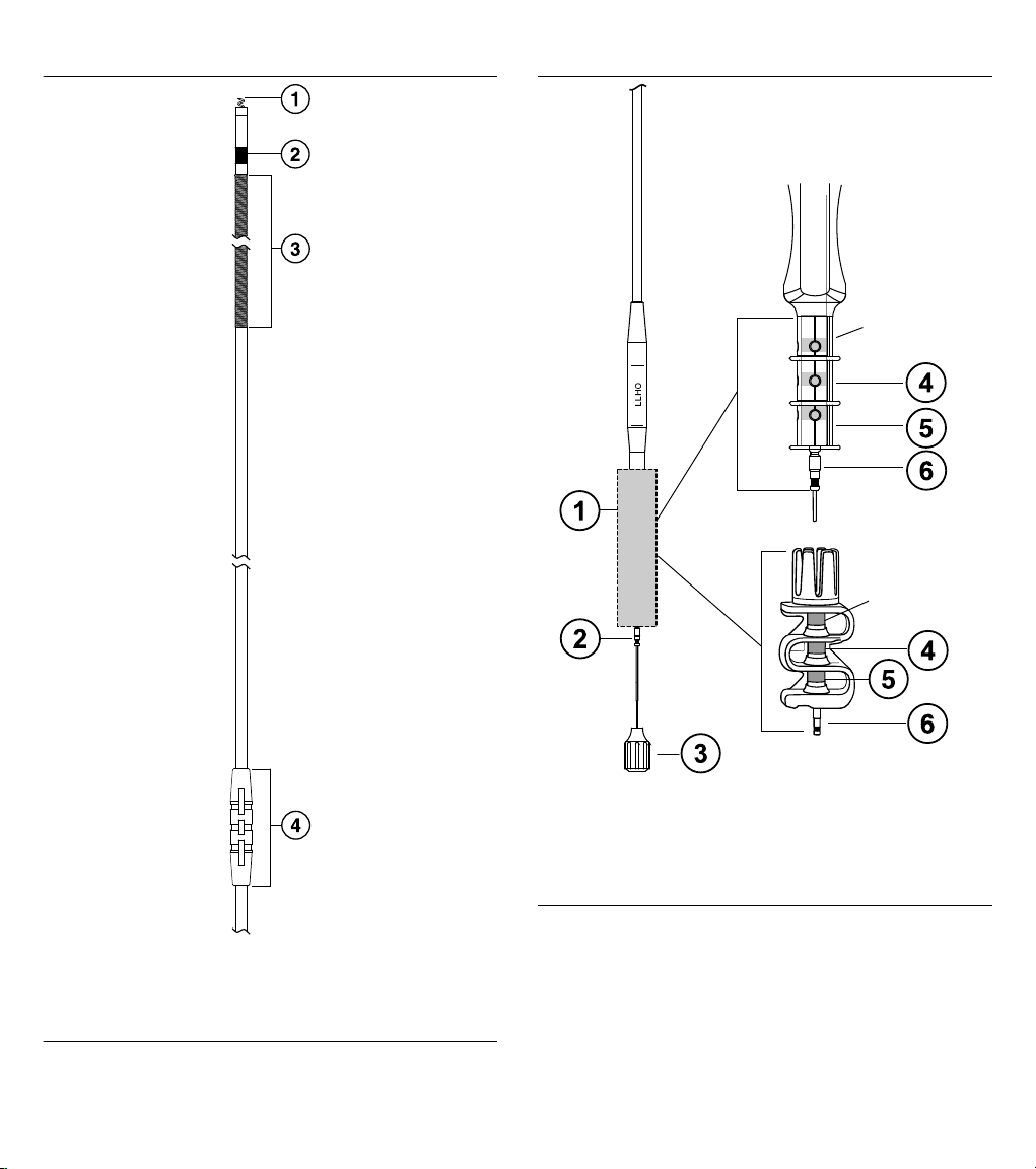
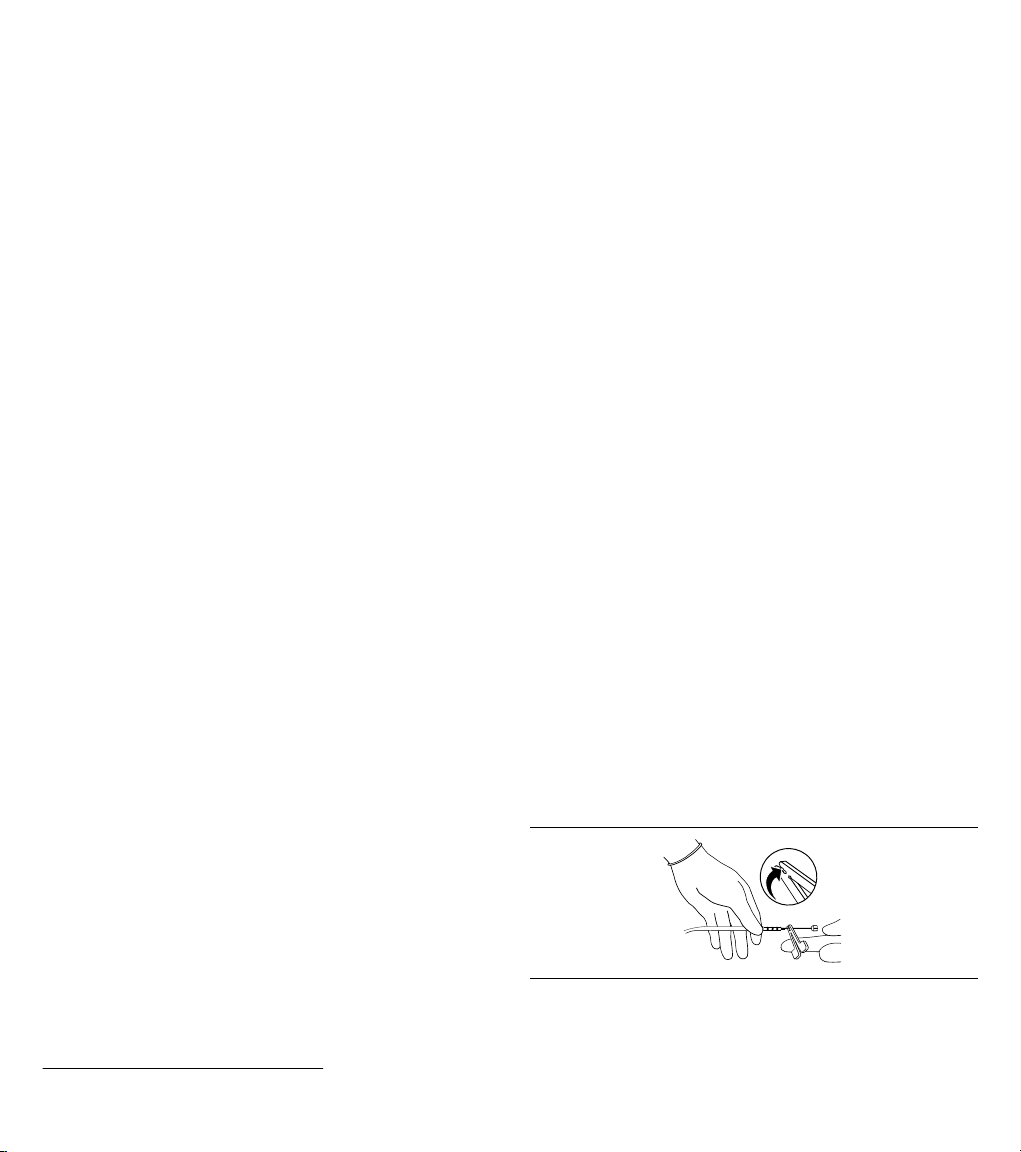
Figure 21. Model 6935M distal lead components
Inactive
Inactive
Figure 22. Model 6935M proximal lead components
1 Helix electrode; surface area: 5.7 mm
2 Ring electrode; surface area: 25.2 mm
3 RV coil electrode; length: 57 mm; surface area: 614 mm2; electrical
shadow area: 506 mm
2
2
2
4 Anchoring sleeve
14
1 AccuRead tool
2 Connector pin
3 Stylet
4 RV contact
5 Ring (+) contact
6 Tip (-)
Page 15

10 Medtronic disclaimer of warranty
For complete warranty information, see the accompanying
warranty document.
Table 5. Explanation of symbols on package labeling (continued)
Symbol Explanation
Authorized representative in the European community
11 Service
Medtronic employs highly trained representatives and engineers
located throughout the world to serve you and, upon request, to
provide training to qualified hospital personnel in the use of
Medtronic products. Medtronic also maintains a professional staff
to provide technical consultation to product users. For more
information, contact your local Medtronic representative, or call or
write Medtronic at the appropriate telephone number or address
listed on the back cover.
12 Explanation of symbols on package labeling
Refer to the package labels to see which symbols apply to this
product.
Table 5. Explanation of symbols on package labeling
Symbol Explanation
Conformité Européenne (European Conformity).
This symbol means that the device fully complies
with AIMD Directive 90/385/EEC (0123).
Do not use if package is damaged
Do not reuse
Upper limit of temperature
For US audiences only
Use by
Reorder number
Serial number
Lot number
Package contents
Product documentation
Accessories
Inner diameter
Lead
Lead length
Open here
Sterilized using ethylene oxide
Caution
Consult instructions for use
Date of manufacture
Manufacturer
Transvenous ventricular lead
Transvenous lead with one defibrillation
electrode
Pace
Sense
Defibrillation
Extendable and retractable screw-in
15
Page 16

Table 5. Explanation of symbols on package labeling (continued)
Symbol Explanation
Steroid-eluting
Lead introducer
Lead introducer with guide wire
MR Conditional symbol. The Medtronic SureScan
defibrillation system is MR Conditional and is
designed to allow implanted patients to undergo
an MRI scan under the specified MRI conditions
for use.
SureScan symbol
16
Page 17

Page 18

Medtronic, Inc.
*M961371A001*
710 Medtronic Parkway
Minneapolis, MN 55432
USA
www.medtronic.com
+1 763 514 4000
Medtronic USA, Inc.
Toll-free in the USA (24-hour technical consultation for
physicians and medical professionals)
Bradycardia: +1 800 505 4636
Tachycardia: +1 800 723 4636
Europe/Middle East/Africa
Medtronic International Trading Sàrl
Route du Molliau 31
Case Postale 84
CH-1131 Tolochenaz
Switzerland
+41 21 802 7000
Technical manuals
www.medtronic.com/manuals
© 2015 Medtronic, Inc.
M961371A001 B
2015-07-05
 Loading...