

Page 1

CARDIOBLATE® 68000
SURGICAL ABLATION SYSTEM
Technical Manual
Page 2

Page 3

Explanation of symbols
European Conformity. This symbol means that the device fully complies with
European Council Directive 93/42/EEC.
Attention, See Instructions for Use
Dangerous Voltage
Reorder Number
Serial Number
Manufacturer
Temperature Limitation
Nonsterile
Content
Atmospheric Pressure Limitation
Humidity Limitation
Date of Manufacture
Type CF Applied Part
Neutral Electrode Isolated from Earth High Frequency
Dispersive Electrode Pad
Electrogram
Monopolar
Bipolar
Danger: Risk of explosion if used in the presence of flammable anesthetics
With Respect To Electric Shock Fire And Mechanical Hazards Only In
Accordance With UL60601-1/CAN/CSA C22.2 No. 601.1
Cardioblate® 68000 Technical Manual i
Page 4

ETL Listing (US/CAN) This device meets the requirement of UL60601,
CAN/CSA C22.2 No. 601-1M90 and IEC60601-2-2
Non-ionizing Radiation
Fuse Marking: Replace Fuses as Marked
Do not dispose of this product in the unsorted municipal waste stream. Dispose
of this product according to local regulations. See http://recycling.medtronic.com
for instructions on proper disposal of this product.
Bipolar Device
Monopolar Device
Overall RF Energy Delivery Time
Transmural
Remote Control Foot Switch
Graph Mode
Volume Level
Impedance
Wattage
Ohms, Unit of Impedance Measurement
RF Energy Delivery Button
Active Ablation Time
Universal Serial Bus (USB) Port Connector
Error Message Explanation
Watts, Unit of Energy Measurement
Maximum Limit
Minimum Limit
ii Cardioblate® 68000 Technical Manual
Page 5

OFF (AC Power)
ON (AC Power)
Warning or Error Message
For US Audiences Only
China RoHS Standard (SJ/T11364-2006) Electronic Information Products
Pollution Control Symbol. The number represents the years the device can be
used before it must be recycled (environmental protection use period).
Authorized Representative in the European Community
Cardioblate® 68000 Technical Manual iii
Page 6

iv Cardioblate® 68000 Technical Manual
Page 7

Table of Contents
How to Use This Manual vii
Changing the Language Option vii
1 Overview 1-1
System Description 1-2
Indications for Use 1-4
Contraindications 1-5
Warnings and Precautions 1-5
Adverse Events 1-10
2 Generator Description 2-1
Components 2-2
Displays, Connectors, and Controls 2-3
Audible Tones 2-9
Specifications 2-9
Output Power Diagrams 2-12
Electromagnetic Emissions and Immunity Declaration
(EN60601-1-2) 2-14
Applicable Standards 2-18
3 Generator Operation 3-1
Quick Reference Guide 3-2
Selecting and Attaching a Dispersive Electrode 3-3
Preparing and Powering Up the Generator 3-4
Connecting a Cardioblate
Verifying Generator Recognition of Attached Devices 3-8
Disconnecting the Cardioblate
Setting the RF Energy Mode and Parameters 3-9
Monopolar Mode Selection and Use 3-9
Bipolar Mode Selection and Use 3-14
Options 3-17
Powering Down the Generator 3-23
®
Ablation Device 3-6
®
Ablation Devices 3-9
4 Safety Shutdown and Troubleshooting 4-1
Safety Shutdown Conditions 4-2
Safety Shutdown Messages 4-3
Cardioblate® 68000 Technical Manual v
Page 8

Other Messages 4-7
System Shutdown 4-7
5 Device Maintenance and Service 5-1
Replacing the Generator Fuse 5-2
Cleaning the Generator 5-2
Periodic Technical and Safety Inspection 5-3
Service 5-4
6Warranty6-1
Medtronic Warranty Information 6-2
A Index A-1
vi Cardioblate® 68000 Technical Manual
Page 9

How to Use This Manual
This guide presents information for users of the Model 68000
Cardioblate
®
Generator. It contains information about the
following:
■
Overview
®
This chapter is a brief overview of the Cardioblate
and the accessories that compose the Cardioblate
Generator
®
Surgical
Ablation System.
■
Generator Description
This chapter identifies and describes the generator case,
controls, connectors, touch-screen information fields, and
touch-screen interactive fields.
■
Generator Operation
This chapter provides instructions for preparing the patient,
setting up the generator system, and treating the patient.
■
Safety Shutdown and Troubleshooting
This chapter provides information on safety shutdown
conditions and messages and trouble-shooting.
■
Device Maintenance and Service
This chapter identifies how to replace the fuse and clean the
generator and provides information on technical and safety
inspections.
■
Warranty
This chapter describes the device and accessories warranties.
Changing the Language Option
This information is also provided in Chapter 3.
Note: English is the default language for the Medtronic
Cardioblate
To change the language option:
1. Access the Options Menu
To access the Options Menu, press the Options button
located in the lower-right side of the RF panel screen.
®
68000 Generator.
Cardioblate® 68000 Technical Manual vii
Page 10

2. Select the Advanced screen
Select the Advanced option, which will bring up the Advanced
Options screen.
3. Select the Language button
Press the Language button located in the lower left-side of the
Advanced Options screen. Select the desired language. The
following languages are available for use:
■
English
■
German
viii Cardioblate® 68000 Technical Manual
Page 11

■
Spanish
■
French
■
Italian
■
Greek
Note: At any time, the backwards arrow button can be used
to return to a previous screen.
Cardioblate® 68000 Technical Manual ix
Page 12

x Cardioblate® 68000 Technical Manual
Page 13

System Description 1-2
Indications for Use 1-4
Contraindications 1-5
Warnings and Precautions 1-5
Adverse Events 1-10
Overview1
1
Cardioblate® 68000 Technical Manual 1-1
Page 14

Chapter 1
System Description
System Description
The Medtronic® Cardioblate® Surgical Ablation System
Model 68000 consists of a generator and included accessories.
The surgical ablation system is designed to deliver radiofrequency
(RF) energy to selected sites via a Cardioblate
device (hereafter referred to only as the ablation device). The
generator is line-powered and is designed to be placed on a table.
The high-impact plastic generator case has a convenient carrying
handle and a display screen. An easy-to-use latch mechanism
secures and releases the display screen. The display screen
provides users with real-time treatment information in graphical
and digital formats. Message fields on the display screen also
provide critical information during the treatment procedure.
The user interface includes a touch-screen that responds to
gloved and ungloved touch. When the user touches a
control-button icon on the screen, the system performs the
function selected if no errors exist.
The user interface also provides unique audible tones to
automatically notify the user of the treatment status or alert
condition.
®
surgical ablation
Key features include the following:
Touch screen operation – The generator parameters can be
easily set and adjusted using the touch screen panel.
RF energy modes – The generator controls the amount of
energy being delivered through the ablation device in one of the
following energy modes:
■
In monopolar mode, the generator monitors and controls the
amount of RF energy delivered to the tissue between the
ablation device and the dispersive electrode at a preselected
power setpoint throughout the ablation.
■
In bipolar and enhanced bipolar modes, the generator
monitors tissue impedance and adjusts the amount of power
delivered to the tissue between the active electrode jaws to
create transmural lesions.
■
EGM throughput is available in monopolar mode only.
1-2 Cardioblate® 68000 Technical Manual
Page 15

Package Contents
1
3
2
Overview
System Description
Safety shutdowns – RF energy delivery stops if the
operator-selected or manufacturer-programmed impedance,
power, or temperature limits are exceeded. If a warning message
appears, see Chapter 4, “Safety Shutdown and Troubleshooting,”
for detailed information.
The Cardioblate® Surgical Ablation System (Model 68000)
package may contain the following items (Figure 1-1):
■
One Model 68000 generator
■
One Model 60883 remote control foot switch
■
One power cord: Model 4807
■
Product literature
Figure 1-1. 68000 Generator
Cardioblate® 68000 Technical Manual 1-3
Page 16

Chapter 1
Indications for Use
1. Model 68000 generator
2. Power cord
3. Remote control foot switch
Other Applicable Accessories
The following accessories are applicable to the Cardioblate®
Surgical Ablation System but are not included in the Model 68000
package:
■
Medtronic® Cardioblate® surgical ablation devices
■
Model 60813 - Cardioblate® Surgical Ablation Pen
■
Model 60814 - Cardioblate® Surgical Ablation XL Pen
■
Model 60831 - Cardioblate® Surgical Ablation BP2 Device
■
Model 60841 - Cardioblate® Surgical Ablation LP Device
■
Models 49260/49261 - Cardioblate® Gemini™ Surgical
Ablation Devices
■
Medtronic released products labeled for use with the
Cardioblate
Caution: Cardioblate
be used with the Cardioblate
Caution: Only use Medtronic
Medtronic recommended accessories. The safety of use with
other surgical ablation devices, catheters, or accessories has
not been assessed.
■
Dispersive electrode with a conductive adhesive and a
minimum surface area of 100 cm
IEC 60601-2-2).
■
Model 60889 - Medtronic® Cardioblate® Diagnostic Kit
®
68000 Generator as an external device
®
bipolar device, Model 60821, cannot
®
68000 Generator.
®
ablation devices and
2
(must be compliant with
Indications for Use
The Cardioblate® Surgical Ablation System is intended to ablate
cardiac tissue during cardiac surgery using radiofrequency
energy.
1-4 Cardioblate® 68000 Technical Manual
Page 17

Contraindications
The Cardioblate® Surgical Ablation System is contraindicated for
patients with active endocarditis at the time of surgery.
Warnings and Precautions
General
Product literature – Do not attempt to operate the Cardioblate
Surgical Ablation System or connect the ablation device to the
generator prior to completely reading and understanding the
product literature for the Cardioblate
and the ablation device.
System compatibility – Only use Medtronic ablation devices and
Medtronic-recommended accessories. The safety of use with
other surgical ablation devices, catheters, or accessories has not
been assessed.
Overview
Contraindications
®
Surgical Ablation System
®
Single Use Devices – Medtronic ablation devices designed for
use with this generator are intended for single-time use. The
Cardioblate Generator has functionality to prevent the reuse of the
surgical ablation devices.
Accessories – Regularly inspect and test reusable cables and
accessories. Do not use any cable or accessory that appears to
be damaged, and take the following precautions:
■
Inspect for insulation damage, such as brittleness, cracking,
thinning or bare spots.
■
Replace damaged accessories.
See Chapter 2, “Generator Description,” for detailed information
regarding accessories.
Electrical shock and/or burns – To avoid the risk of electrical
shock and/or burns to the patient, do not touch the patient while
touching the outer housing or connections on the Cardioblate
®
generator. Do not allow the patient to come into contact with
grounded metal surfaces during RF energy delivery.
Cardioblate® 68000 Technical Manual 1-5
Page 18

Chapter 1
Warnings and Precautions
Electrostatic Discharge (ESD) is the sudden transfer or discharge
of static electricity from one object to another. Human bodies can
create ESD charges of up to 25,000 volts.
■
Connector pins identified with the ESD warning symbol should
not be touched. NO connections should be made to these
connectors unless ESD precautionary procedures are
followed. ESD applied to one of these connectors may cause
the generator to display an error message and interrupt RF
energy delivery until the message is acknowledged and/or
removed.
■
Precautionary procedures include the following:
– Prevent electrostatic charge build-up (eg, air conditioning,
humidification, conductive floor coverings, and
nonsynthetic clothing);
– Discharge one’s body to the frame of the equipment or
system, to earth, or a large metal object prior to making a
contact;
– Bond oneself by means of a wrist strap to the equipment or
system, or to earth prior to making a contact.
Ablation Therapy Hazards
Lesions – The long-term effects of lesions created by RF ablation
have not been established; note the following:
■
Any long-term effects of lesions in proximity to the conduction
system or coronary vasculature are unknown.
■
The risks/benefits in asymptomatic patients have not been
studied.
Artrioventricular (AV) node modification or septal accessory
pathway ablation – Patients undergoing AV node modification or
septal accessory pathway ablation are at risk for complete AV
blockage:
■
Closely monitor AV conduction after RF energy delivery
Using RF energy near implanted devices – RF energy may
adversely affect implanted devices, such as pacemakers and
implantable cardioverter-defibrillators (ICDs). To avoid this, do the
following:
■
Keep external sources of pacing and defibrillation available
during ablation.
■
Deactivate ICD detection during RF energy delivery.
1-6 Cardioblate® 68000 Technical Manual
Page 19

Overview
Warnings and Precautions
■
Exercise extreme caution when delivering ablation energy in
close proximity to implanted leads.
■
Perform complete implantable device testing before and
after ablation.
Electrosurgery near flammable materials – The risk of igniting
flammable gases or other materials is inherent in electrosurgery
and cannot be eliminated by device design. Flammable agents
used for cleaning or disinfecting, or as solvents of adhesives,
should be allowed to evaporate before the application of high
frequency surgery. There is a risk of pooling of flammable
solutions under the patient or in body depressions such as the
umbilicus, and in body cavities such as the vagina. Any fluid
pooled in these areas should be mopped up before RF surgical
equipment should be used. Attention should be called to the
danger of ignition of endogenous gases. Take precautions to
restrict flammable materials and substances from the
electrosurgical site. Flammable materials may come in the
following forms:
■
Anesthetics or skin preparation agents.
■
Natural chemicals produced within body cavities.
■
Chemicals originating in surgical drapes or other materials.
Unintentional patient burns – To avoid unintentional burns to
the patient during RF energy delivery, do the following:
■
Minimize the distance between the dispersive electrode and
the operating field.
■
Minimize skin-to-skin contact between parts of the patient's
body by covering these areas with dry gauze.
■
Place monitoring electrodes as far as possible from surgical
electrodes to minimize burns at the site of the monitoring
electrodes.
■
When using multiple ablation devices, remove those devices
not actively in use from patient contact. In all cases, monitoring
systems incorporating high frequency current-limiting devices
are recommended.
Handling RF devices during therapy – The generator is
capable of delivering significant RF energy. Do not touch the
ablation electrode of the ablation device or the dispersive
electrode or both electrodes on a bipolar device while operating
the generator.
Cardioblate® 68000 Technical Manual 1-7
Page 20

Chapter 1
Warnings and Precautions
Equipment failure – The failure of the generator or hand piece
could result in an unintended increase of output power. See
Chapter 4, “Safety Shutdown and Troubleshooting,” for detailed
information.
Generator Operation
High impedance – Monitor the device impedance measurement
display during RF energy delivery. If abnormally high impedance
is observed, examine the ablation electrode for coagulum. If
coagulum is present or any irrigation opening is found to be
blocked, remove coagulum or replace the ablation device prior to
continuing the procedure.
If high impedance is preventing ablation from occurring, do the
following:
■
■
■
Check all connections.
Check for obvious defects or misapplication of the dispersive
electrode (if the monopolar device is in use).
If a patient must be repositioned during a procedure, verify that
there is proper contact between the patient and the dispersive
electrode after the patient has been moved.
Low impedance – Some patients may have an abnormally low
impedance between the ablation device and dispersive electrode,
causing a safety shutdown. Moving the dispersive electrode to a
location on the body that is farther from the device may correct this
situation.
Fan – Do not obstruct the cooling fan located on the rear of the
generator (Figure 2-5). Obstruction of the cooling fan could result
in over-heating and device shutdown.
Cardioblate® Ablation Device Use
See Directions for Use for Cardioblate® ablation devices being
used during the procedure.
Medical Environment
Line-powered equipment – Properly ground all line-powered
equipment used on or in the vicinity of the patient. An ablation
device connected to an RF generator constitutes a direct,
low-resistance current pathway to tissue, including the
myocardium.
1-8 Cardioblate® 68000 Technical Manual
Page 21

Overview
Warnings and Precautions
Necessary environment – Ablation procedures should be
performed only by trained personnel in a fully equipped operating
room as follows:
■
An emergency cardiovascular team should be available during
the ablation procedure in case of a cardiovascular emergency.
■
The ablation device should be used only by or under the
supervision of physicians trained in cardiac surgery and
experienced in surgical ablation procedures.
Generator storage temperature – If the generator has been
stored at temperatures greater than 30°C or less than 15°C, allow
the generator to reach room temperature or wait at least
60 minutes before use, whichever is greater.
Fluid ingress – The generator may not function correctly if the
electronic circuitry or the connectors are wet; note the following:
■
Do not allow any fluid or moisture into the generator or any
connector or cables.
■
Do not hang fluids above the generator.
■
Do not immerse the cables into fluids.
Electromagnetic interference (EMI) – EMI produced by the
generator during normal operation may adversely affect the
performance of other equipment.
Please refer to applicable standards for additional information.
Cardioblate® 68000 Technical Manual 1-9
Page 22

Chapter 1
Adverse Events
Adverse Events
The potential adverse events related to the use of ablation
systems include, but are not limited to, the following:
■
tissue perforation
■
extension of extracorporeal
bypass
■
perioperative heart rhythm
disturbances (atrial and/or
ventricular)
■
postoperative embolic
complications
■
pericardial effusion or
tamponade
■
injury to the great vessels
■
valve leaflet damage
■
conduction disturbances
(SA/AV node)
■
acute ischemic myocardial
event
■
thrombus formation
■
nerve damage
■
unintentional burns
■
pericarditis
■
pleural effusion
■
esophageal perforation
■
death
■
coronary sinus
perforation
■
coronary artery spasm
■
atrial lead dislodgement
■
hypotension
■
pulmonary vein stenosis
■
cerebrovascular accident
■
transient ischemic attack
■
blood loss
1-10 Cardioblate® 68000 Technical Manual
Page 23

Generator Description2
Components 2-2
Displays, Connectors, and Controls 2-3
Audible Tones 2-9
Specifications 2-9
Output Power Diagrams 2-12
Electromagnetic Emissions and Immunity Declaration
(EN60601-1-2) 2-14
Applicable Standards 2-18
2
Cardioblate® 68000 Technical Manual 2-1
Page 24

Chapter 2
3
4
5
2
1
6
7
8
9
Components
Components
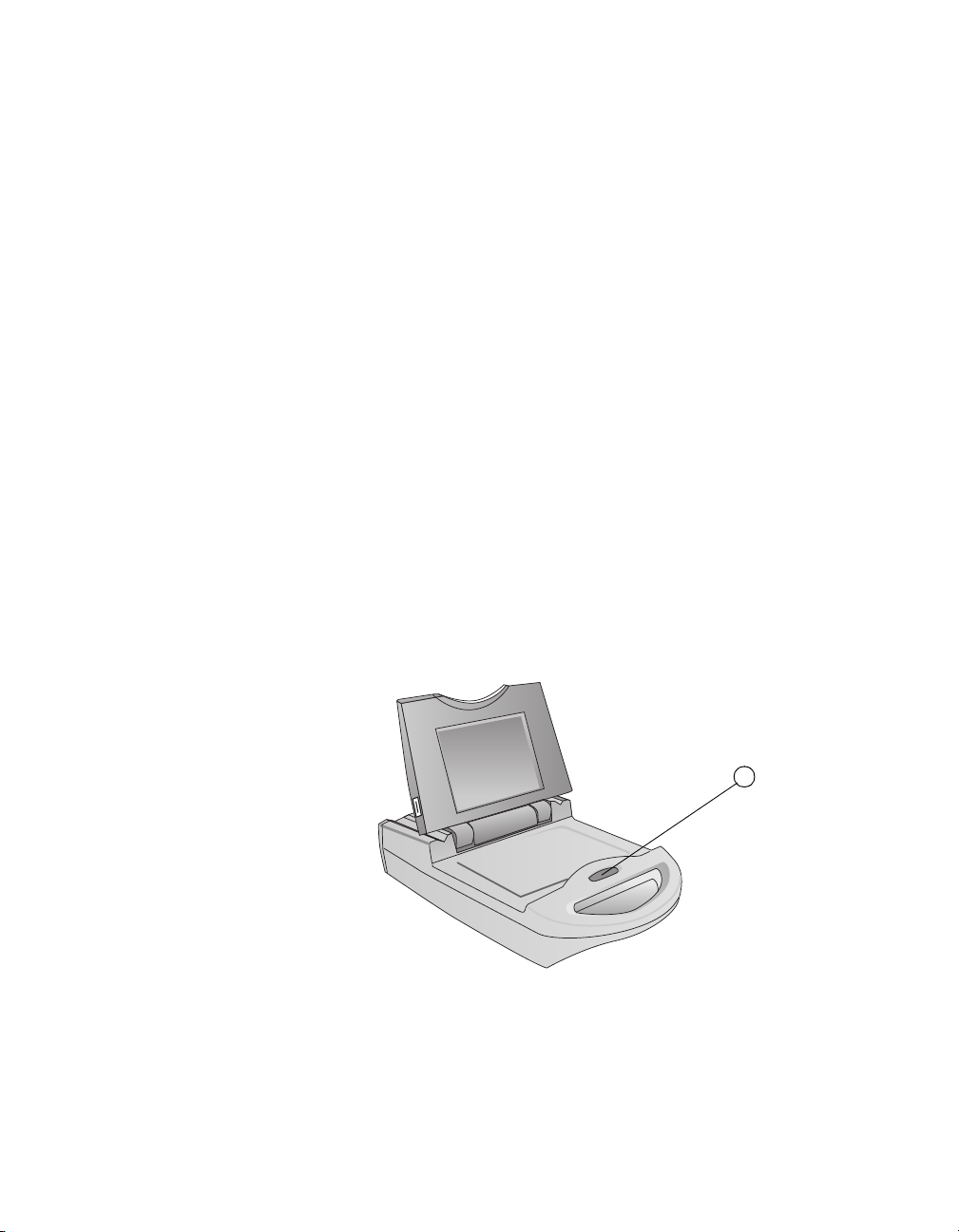
Introduction
The Model 68000 Cardioblate® Generator (Figure 2-1) is
lightweight and portable with state of the art electronics and design
features that provide the user with a safe and effective
Cardioblate
®
Surgical Ablation System.
Front View Back View
Figure 2-1. Model 68000 Cardioblate® Generator Case
The following are the basic user components:
1. Bezel Light Panel
2. USB Port
3. Transport Handle
4. Display Release Button
5. Display Screen
6. Therapy Connector Panel
7. Cooling Fan
8. Optional Device Connector
9. AC Power Panel
At the top of the cover assembly there is a bezel light panel with
three LEDs: two blue and one green. When the center green LED
is lit, it indicates that the AC power is on. When the two blue LEDs
are flashing, the generator software is performing its self-test.
When the blue LEDs are solid, RF energy is being applied and a
lesion is in progress.
2-2 Cardioblate® 68000 Technical Manual
Page 25

Displays, Connectors, and Controls
1
3
4
2
Displays, Connectors, and Controls
Right Side Panel
The applicable Medtronic® Cardioblate® surgical ablation devices
and the dispersive electrode cable can be connected to the
Cardioblate
on the right side of the generator.
1. Cardioblate
This multipin connector provides the interface to a bipolar ablation
device.
2. Cardioblate
This multipin connector provides the interface to a monopolar
ablation device.
®
Generator via the therapy connector panel located
Figure 2-2. Right Side Therapy Connector Panel
®
Bipolar ablation device connector
®
Monopolar ablation device connector
Generator Description
3. Dispersive electrode connector
This connector provides the interface to the dispersive electrode via
the dispersive electrode cable.
4. EGM Connection
This multipin connector provides the interface to EGM monitoring
equipment.
Cardioblate® 68000 Technical Manual 2-3
Page 26

Chapter 2
USB Port
Displays, Connectors, and Controls
Left Side Panel
On the left side panel there is a Universal Serial Bus (USB) port,
which is intended for Medtronic field service personnel. It allows
the field service personnel to connect a USB flash memory device
to the generator. The flash memory device can be used for
uploading application updates and for downloading stored data
from the generator.
The Cardioblate
loaded via this USB port. Refer to the product literature for detailed
instructions.
®
Diagnostic Kit (Model 60889) application is also
Figure 2-3. USB Port location
2-4 Cardioblate® 68000 Technical Manual
Page 27

Touch Screen Display
1
2
3
4
5
6
7
8 9
10 11 12
Display Screen
The color (640x480 pixels), liquid-crystal-display (LCD) screen
closes into the case for storage and flips open on a hinge for use.
The display screen provides users with real-time treatment
information in graphical and digital formats. The screen’s hinge
allows adjustment for different viewing angles. When the
generator is on, the screen also remains on at all times and in all
positions; there is no “screen saver” mode. Figure 2-4 details the
touch screen display present upon start-up.
Generator Description
Displays, Connectors, and Controls
Figure 2-4. Touch screen display
1.
Total RF time
The cumulative amount of RF energy delivery time, since the
generator was powered ON, is displayed. The counter resets to
0:00 when the generator is powered OFF and then ON.
2.
RF timer measurement display
This displays the duration (minutes:seconds) of each RF delivery
cycle. The display automatically resets to 0:00 when the RF energy
delivery begins and measures until RF energy delivery stops. The
elapsed time of the delivered RF cycle is displayed until the next
RF cycle begins.
Cardioblate® 68000 Technical Manual 2-5
Page 28

Chapter 2
Displays, Connectors, and Controls
3.
Impedance measurement display
This displays the measured impedance (Ω). For the monopolar
device, this is between the ablation electrode of the ablation device
and the dispersive electrode during the delivery of RF energy. For
the bipolar device, this is between the jaws of the bipolar device
during delivery of RF energy.
4.
RF power measurement display
This displays the amount of RF power (in watts) being delivered.
5.
Message Box
This displays text messages regarding generator status, including
system warnings.
6.
RF energy button
The RF button both activates and deactivates the delivery of RF
energy to the selected device.
7.
Bipolar button
The bipolar button selects the bipolar mode. This button can only be
selected when a bipolar device is attached.The selected button
remains active while the bipolar mode is in effect.
8.
Monopolar button
The monopolar button selects the monopolar mode. This button can
only be selected when a monopolar device is attached. The
selected button remains active while the monopolar mode is in
effect.
9.
Options
The options button accesses the options menu. For further
information on options, refer to “Options” on page 3-17.
10.
Speaker Volume Level
The speaker volume level icon is the readout for the audio control
buttons. The number of curved lines increase and decrease with the
volume settings. There are five volume levels; the lowest level is still
audible and there is no OFF setting.
11.
Audio control
The audio control buttons adjust speaker volume.
12.
Information button
The information button provides details to the user regarding
possible causes and solutions for device errors.
2-6 Cardioblate® 68000 Technical Manual
Page 29

Rear Panel
1 2 3
4
5
6
7
Generator Description
Displays, Connectors, and Controls
The rear panel (Figure 2-5) contains the AC power, equipotential
ground, and optional device connections. The AC power
connection includes a power-entry plug assembly with an ON/OFF
power switch and two power fuses.
A recessed, equipotential grounding terminal provides convenient
access for grounding the generator with another electronic
devices. There is also a connector for the cable to the optional
Medtronic foot switch Model 60883 that activates the radio
frequency delivery system.
The rear panel USB communications port is to be used only by
Medtronic field service personnel. The port is secured against
unauthorized use.
1.
Fan
Provides constant air flow to cool electronics when power is on.
Do not obstruct the cooling fan. Obstruction of the fan could result
in overheating and device shutdown.
2.
Equipotential ground post
Provides common electrical ground for other electronic devices
being used during the procedure.
3.
USB Port
Connection to USB cable for external digital device
communication. This security-protected connector is for Medtronic
use only.
Figure 2-5. Rear panel
Cardioblate® 68000 Technical Manual 2-7
Page 30

Chapter 2
Displays, Connectors, and Controls
4.
Remote control foot switch connector
This connector provides the interface to the remote control foot
switch.
5.
Power entry connector
This connector provides the interface to AC line power via the
power cord.
6.
Fuse
This housing contains two field-replaceable 3.15 Amp. slow-blow
fuses. Refer to “Replacing the Generator Fuse” on page 5-2.
7.
ON/OFF Switch
Remote Foot Switch
The Model 60883 Remote Foot Switch (Figure 2-6) is an optional
remote control device that connects to the rear panel of the
Model 68000 Cardioblate
switch is properly connected to the generator, the user can press
the foot switch to start RF energy delivery. To stop the RF energy
delivery, the user releases the remote foot switch.
®
Generator. When the remote foot
The connector end of the remote foot switch has an easy-to-use
connector release mechanism. To disconnect the cable from the
generator, pull back on the textured grip ring to release the lock
before removing the connector.
Figure 2-6. Model 60883 Remote Foot Switch
2-8 Cardioblate® 68000 Technical Manual
Page 31

Audible Tones
Generator Description
Audible Tones
Tab le 2-1. Model 68000 audible tones
Generator tone Meaning
Two tones at regularly spaced
intervals
Regularly spaced single
medium-pitch beeps
Regularly spaced dual
medium-pitch beeps
Three low-pitched beeps An error condition has caused a
Continuous medium-pitch tone Transmurality algorithm is complete
Specifications
Model 68000 Generator
Physical characteristics
Dimensions 55 x 35 x 14 cm (21.8 x 13.8 x 5.5 in)
Weight 9.5 kg (21 lbs)
Power requirement 100 - 240 VAC, 270VA, 50 - 60 Hz
Fuse protection Two 250 V, 3.15 Amp. slow-blow fuses
System error that may require a
re-boot
RF energy is being delivered to the
monopolar device
RF energy is being delivered to the
bipolar device
safety shutdown
Table 2 -2. Model 68000 generator specifications
(user accessible)
Cardioblate® 68000 Technical Manual 2-9
Page 32

Chapter 2
Specifications
Tabl e 2 -2. Model 68000 generator specifications (continued)
Functional characteristics
RF power output
setpoint/limit
(Monopolar Mode)
RF power output
setpoint/limit
(Bipolar Mode)
RF power output
setpoint/limit
(Enhanced Bipolar
Mode)
RF power output
frequency
Maximum RF voltage,
between electrodes
Maximum RF Current
Impedance limits
RF timer limit
(Monopolar Mode)
RF timer limit (Bipolar
Mode)
Range: 1 to 50 W
Increment: 1 W
Accuracy: ± 10% or 3 W, whichever is
greater (Impedance ≥ 30 Ω and
Impedance ≤ 400 Ω)
Accuracy: ± 20% or 3 W, whichever is
greater (Impedance < 30 Ω or Impedance
>400Ω)
Range: 15 to 40 W (automatically varying)
Increment: 5 W
Accuracy: ± 10% or 3 W, whichever is
greater (Impedance ≥ 30 Ω and
Impedance ≤ 400 Ω)
Accuracy: ± 20% or 2 W, whichever is
greater (Impedance < 30 Ω or Impedance
>400Ω)
Range: 15 to 55 W
(automatically varying)
Increment: 5 to 10 W, varying
Accuracy: ± 10% or 3 W, whichever is
greater (Impedance ≥ 30 Ω and
Impedance ≤ 400 Ω)
Accuracy: ± 20% or 2 W, whichever is
greater (Impedance < 30 Ω or Impedance
>400Ω)
473 ± 5 kHz
180 Vrms ± 10%
2A ± 150 mA
Range: 12 to 600 Ω
Increment: 5 Ω
Accuracy: ± 15% for 20 to 500 Ω
Accuracy: ± 20% or 5 Ω (whichever is
greater) for 12 to 20 Ω and 500 to 600 Ω
Range: 1 second to 2 minutes, inclusive
Increment: 1 second
Accuracy: ± 1% or 1 second, whichever is
greater
Range: 2 to 40 seconds (automatically
controlled)
2-10 Cardioblate® 68000 Technical Manual
Page 33

Generator Description
Tab le 2-2 . Model 68000 generator specifications (continued)
RF timer limit
(Enhanced Bipolar
Mode)
Default Settings
RF power
Impedance (Monopolar
Mode)
Impedance (Bipolar
Mode)
RF timer
Temperature and
humidity information
Operating temperature
and humidity
Storage/shipping
temperature
and humidity
Rear panel connectors
Fused power connector
Ground post
Remote control foot
switch connector
Side panel connectors
Dispersive electrode
®
Cardioblate
monopolar
ablation device
Cardioblate® bipolar
ablation device
EGM connector
Safety information
a
Lemo® is a registered trademark of Lemo USA, Inc.
Range: 2 to 45 seconds (automatically
controlled)
Monopolar mode: 25 W
Bipolar mode: NA
Maximum: 500 Ω Minimum: 12 Ω
Maximum: 500 Ω Minimum: 12 Ω
Monopolar mode: 2 minutes
10 to 40°C, 80% relative humidity
-40 to 66°C, 95% relative humidity
3-prong fused mains (AC) power
receptacle
Equipotential ground post
®a
3-pin Lemo
receptacle
2-pin return electrode
10-pin Lemo
16-pin Lemo
4-pin Lemo
®
®
®
receptacle
IEC 60601-1, Class I, Type CF, IPX0, no
sterilization, equipment not suitable for
use in the presence of a flammable
anaesthetic mixture with air, oxygen, or
nitrous oxide, continuous operation
UL 60601-1: With respect to electrical
shock, fire, and mechanical hazards, only
in accordance with UL 60601-1
Specifications
Cardioblate® 68000 Technical Manual 2-11
Page 34

Chapter 2
0
20
40
60
80
100
120
0
25
50
100
150
200
250
300
350
400
450
500
550
600
650
700
750
800
850
900
950
1000
100 W
50 W
25 W
Power (W)
Load (OHMS)
Output Power Diagrams
Accessories
®
Medtronic
Model 60883 remote
control foot switch
Dimensions
Cable length
Weight
Connector
Environmental conditions
®
Medtronic
Model 4807, 4808, or
4809 power cord
Length
Connectors
Output Power Diagrams
Table 2 -3. Accessory specifications
13x15x5cm (5x6x2in)
472 cm (15.4 ft)
645g (1.42lbs)
3-pin Lemo
®
IP 68, water resistant
3 m (nominal) (10 ft)
3-pin hospital-grade safety plug
The following diagrams (Figure 2-7 through Figure 2-9) show the
output power versus load impedance at three power setpoints:
25 W, 50 W, and 100 W at cold and warm operating temperatures.
The generator was tested at fixed impedances using noninductive
resistors.
2-12 Cardioblate® 68000 Technical Manual
Figure 2-7. Monopolar Load Curves
Page 35

Generator Description
0
20
40
60
80
100
120
0
25
50
100
150
200
250
300
350
400
450
500
550
600
650
700
750
800
850
900
950
1000
100 W
50 W
25 W
Power (W)
Load (OHMS)
0.0
20.0
40.0
60.0
80.0
100.0
120.0
140.0
160.0
180.0
200.0
0 5 10 15 20 25 30 35 40 45 50
25 Ohms
50 Ohms
100 Ohms
200 Ohms
300 Ohms
400 Ohms
500 Ohms
600 Ohms
700 Ohms
0.0
20.0
40.0
60.0
80.0
100.0
120.0
140.0
160.0
180.0
200.0
0 5 10 15 20 25 30 35 40 45 50
25 Ohms
50 Ohms
100 Ohms
200 Ohms
300 Ohms
400 Ohms
500 Ohms
600 Ohms
700 Ohms
0.0
20.0
40.0
60.0
80.0
100.0
120.0
140.0
160.0
180.0
200.0
0 5 10 15 20 25 30 35 40 45 50
25 Ohms
50 Ohms
100 Ohms
200 Ohms
300 Ohms
400 Ohms
500 Ohms
600 Ohms
700 Ohms
Output Voltage (Vrms)
Power Setting (W)
Output Power Diagrams
Figure 2-8. Bipolar Load Curves
Figure 2-9. Voltage Curve
Cardioblate® 68000 Technical Manual 2-13
Page 36

Chapter 2
Electromagnetic Emissions and Immunity Declaration (EN60601-1-2)
Electromagnetic Emissions and Immunity Declaration
(EN60601-1-2)
Table 2 -4. Electromagnetic Emissions
The Model 68000 Generator is intended for use in the electromagnetic environment specified
below. The customer or the user of the generator should ensure that it is used in such an
environment.
Emissions test Compliance Electromagnetic Environment –
Radio-frequency (RF) emissions
CISPR 11
RF emissions
CISPR 11
Harmonic emissions
IEC/EN 61000-3-2
Voltage fluctuations/
flicker emissions
IEC/EN 61000-3-3
The Model 68000 Generator is intended for use in the electromagnetic environment specified
below. The customer or the user of the generator should ensure that it is used in such an
environment.
Immunity Test EN 60601
Test Level
Electrostatic
discharge (ESD):
IEC/EN 61000-4-2
±6 kV contact
±8 kV air
Group 2 The Model 68000 must emit
electromagnetic energy in order to
perform its intended function.
Nearby electronic equipment may
be affected.
Class A The Model 68000 is suitable for use
Class A
Complies
Tab le 2-5. Electromagnetic Immunity
Compliance Level Electromagnetic
±6 kV contact
±8 kV air
in all establishments other than
domestic and those directly
connected to the public low-voltage
power supply network that supplies
buildings used for domestic
purposes.
Guidance
Environment – Guidance
Floors should be wood,
concrete, or ceramic tile. If
floors are covered with
synthetic material, the
relative humidity should be
at least 30%.
2-14 Cardioblate® 68000 Technical Manual
Page 37

Electrical fast
transient/burst:
IEC/EN 61000-4-4
Surge:
IEC/EN 61000-4-5
Voltage dips, short
interruptions and
voltage variations
on power supply
input lines:
IEC/EN 61000-4-11
Generator Description
Electromagnetic Emissions and Immunity Declaration (EN60601-1-2)
Table 2 -5. Electromagnetic Immunity
±2 kV for power
supply lines
±1 kV for input/output
lines
±1 kV line(s) to line(s)
±2 kV line(s) to Earth
<5% U
T
(>95% dip in UT)
for 0.5 cycle
40% U
T
(60% dip in UT)
for 5 cycles
±2 kV for power supply
lines
±1 kV for input/output
lines
±1 kV line(s) to line(s)
±2 kV line(s) to Earth
<5% U
T
(>95% dip in UT)
for 0.5 cycle
40% U
T
(60% dip in UT)
for 5 cycles
Main power quality should
be that of a typical
commercial or hospital
environment.
If the user of the device
requires continued
operation during power
main interruptions, it is
recommended that the
device be powered from an
uninterruptible power
supply or a battery.
Power frequency
(50/60 Hz)
magnetic field:
IEC/EN 61000-4-8
Note: U
is the A.C. mains voltage prior to application of the test level.
T
70% U
T
(30% dip in UT)
for 25 cycles
<5% U
T
70% U
T
(30% dip in UT)
for 25 cycles
(>95% dip in UT)
for 25 seconds
3 A/m 3 A/m Power frequency magnetic
fields should be at levels
characteristic of a typical
location in a typical
commercial or hospital
environment.
Cardioblate® 68000 Technical Manual 2-15
Page 38

Chapter 2
Electromagnetic Emissions and Immunity Declaration (EN60601-1-2)
Tabl e 2 -6. Electromagnetic Immunity, IEC 60601-1-2 Table 204
Immunity Test EN 60601
Test Level
Portable and mobile RF communications equipment should be used no closer to any part of the
Model 68000, including cables, than the recommended separation distance calculated from the
equation applicable to the frequency of the transmitter.
Compliance Level Electromagnetic
Environment — Guidance
Recommended separation
distance
Conducted RF
IEC/EN 61000-4-6
Radiated RF
IEC/EN 61000-4-3
3Vrms
150 kHz to 80 MHz
3V/m
80 MHz to 2.5 GHz
3Vrms d=1.2√ P
3V/m d=1.2√ P 80 MHz to 800 MHz
d=2.3√ P 800 MHz to 2.5 GHz
Where P is the maximum output power rating of the transmitter in watts (W) according to the
transmitter manufacturer and d is the recommended separation distance in meters (m).
Field strengths from fixed RF transmitters, as determined by an electromagnetic site survey,
should be less than the compliance level in each frequency range.
b
Interference may occur in the vicinity of equipment marked with the following symbol:
Notes:
■
At 80 MHz and 800 MHz, the higher frequency range applies.
■
These guidelines may not apply in all situations. Electromagnetic propagation is affected by
absorption and reflection from structures, objects, and people.
a
Field strengths from fixed transmitters, such as base stations for radio (cellular/cordless) telephones and land
mobile radios, amateur radio, AM and FM radio broadcast, and TV broadcast cannot be predicted
theoretically with accuracy. To assess the electromagnetic environment due to fixed RF transmitters, an
electromagnetic site survey should be considered. If the measured field strength in the location in which the
Model 68000 is used exceeds the applicable RF compliance level above, the Model 68000 should be
observed to verify normal operation. If abnormal performance is observed, additional measures may be
necessary, such as reorienting or relocating the device.
b
Over the frequency range 150 kHz to 80 MHz, field strengths should be less than 3 V/m.
a
2-16 Cardioblate® 68000 Technical Manual
Page 39

Generator Description
Electromagnetic Emissions and Immunity Declaration (EN60601-1-2)
Table 2 -7. Recommended separation distances between portable and mobile radio frequency
(RF) Communication equipment and the Model 68000 Generator. IEC/EN 60601-1-2 Table 206
The Model 68000 Generator is intended for use in an electromagnetic environment in which
radiated RF disturbances are controlled. The customer or the user of the generator can help
prevent electromagnetic interference by maintaining a minimum distance between portable and
mobile RF communications equipment (transmitters) and the generator as recommended below,
according to the maximum output power or the communications equipment.
Rated maximum
output power of
Separation distance according to frequency of transmitter
(m)
transmitter
150 kHz to 80 MHz 80 MHz to 800 MHz 800 MHz to 2.5 GHz
(W) d = 1.2√ Pd=1.2√ Pd=2.3√P
0.01 0.35 0.12 0.23
0.1 1.1 0.38 0.73
1 3.5 1.2 2.3
10 11 3.8 7.3
100 35 12 23
For transmitters rated at a maximum output power not listed above, the recommended
separation distance d in meters (m) can be estimated using the equation applicable to the
frequency of the transmitter, where P is the maximum output power rating of the transmitter in
watts (W) according to the transmitter manufacturer.
Notes:
■
At 80 MHz and 800 MHz, the separation distance for the higher frequency range applies.
■
These guidelines may not apply in all situations. Electromagnetic propagation is affected by
absorption and reflection from structures, objects, and people.
Cautions:
■
Do not use non-Medtronic components with Medtronic in-line-powered external devices.
The use of non-Medtronic components may result in damage to Medtronic components,
increased emissions, or decreased electromagnetic immunity of the Medtronic devices or
systems.
■
Do not use Medtronic in-line-powered external devices adjacent to, or stacked with, other
electronic devices. Using Medtronic devices in these configurations may result in decreased
electromagnetic immunity of the Medtronic devices or systems.
®
RF Cable: The Medtronic
Cardioblate® surgical ablation devices’ cable length is approximately
3 m in length.
Cardioblate® 68000 Technical Manual 2-17
Page 40

Chapter 2
Applicable Standards
Applicable Standards
IEC 60601-1
IEC 60601-1-AM1
IEC 60601-1-AM2
IEC 60601-1-2 Electromagnetic compatibility
IEC 60601-2-2 Medical electrical equipment - Part 2: Particular
EN 60601-1-4 Medical electrical equipment - Part 1: General
UL 60601-1 Grounded construction, ordinary connection
FCC Part 18 FCC standard for EMI/EMC requirements
Class I, Type CF, ordinary equipment, no
sterilization, benign environment, continuous
mode of operation, applied part specifically
designed for contact directly with the heart
requirements for the safety of high-frequency
surgical equipment
requirements for safety - 4. collateral standard:
programmable electrical medical systems
This equipment has been tested and found to comply with the
limits for medical devices to IEC 60601-1-2 [or EN 60601-1-2 or
Medical Device Directive 93/42/EEC]. This testing shows the
device provides reasonable protection against harmful
interference in a typical medical installation. However, there is no
guarantee that interference will not occur in a particular
installation. If this equipment does cause harmful interference to
other devices or is negatively impacted by other devices, the user
is encouraged to try to correct the interference by one or more of
the following measures:
■
Reorient or relocate the devices.
■
Increase the separation between the devices.
■
Connect the equipment to an outlet on a different circuit.
■
Consult the manufacturer or field service technician for help.
2-18 Cardioblate® 68000 Technical Manual
Page 41

Generator Operation
Quick Reference Guide 3-2
Selecting and Attaching a Dispersive Electrode 3-3
Preparing and Powering Up the Generator 3-4
Connecting a Cardioblate® Ablation Device 3-6
Verifying Generator Recognition of Attached Devices 3-8
Disconnecting the Cardioblate® Ablation Devices 3-9
Setting the RF Energy Mode and Parameters 3-9
Monopolar Mode Selection and Use 3-9
Bipolar Mode Selection and Use 3-14
3
3
Options 3-17
Powering Down the Generator 3-23
Cardioblate® 68000 Technical Manual 3-1
Page 42

Chapter 3
Quick Reference Guide
Quick Reference Guide
A quick reference guide is located on the surface of the generator,
under the display screen as shown in Figure 3-1. Detailed steps
regarding setup and operation are on the following pages. Refer
to the ablation device Instructions for Use for specific information
on device use.
1. Attach the dispersive electrode.
2. Plug in the power cord and foot switch.
3. Set up saline irrigation.
4. Attach devices to the generator after the self-test is complete.
3-2 Cardioblate® 68000 Technical Manual
Figure 3-1. Quick Reference Guide
Page 43

Generator Operation
Back Mid-back Buttocks
Selecting and Attaching a Dispersive Electrode
Selecting and Attaching a Dispersive Electrode
Selecting a Dispersive Electrode and Application Site
Note: A dispersive electrode is used only with a monopolar
device.
1. Select a dispersive electrode with the following
characteristics:
■
The dispersive electrode must have a conductive adhesive
backing and a minimum surface area of 100 cm
■
The dispersive electrode must meet or exceed American
National Standards Institute (ANSI) and Association for the
Advancement of Medical Instrumentation (AAMI)
requirements.
Refer to the product literature packaged with the dispersive
electrode for additional information on the use of the
dispersive electrode.
2. Select an application site for the dispersive electrode that
allows the entire area of the dispersive electrode to adhere to
the patient's body and is as close to the heart as possible.
The recommended sites are the patient's back, mid-back, or
buttocks (Figure 3-2).
2
.
Caution: Place electrocardiogram (ECG) electrodes and
other monitoring probes as far away as possible from the
ablation site and the attached dispersive electrode to reduce
the risk of burns.
Figure 3-2. Dispersive electrode application site
Cardioblate® 68000 Technical Manual 3-3
Page 44
Chapter 3
1
Preparing and Powering Up the Generator
Attaching the Dispersive Electrode
1. Shave, clean, and dry the application site.
2. Apply the dispersive electrode to the application site
according to the instructions in the dispersive electrode
manufacturer’s product literature.
3. Use antistatic (nonconductive) sheeting to keep the patient
from coming into contact with metal parts that are grounded
or can act as a ground (eg, the operating table, supports).
4. Place dry gauze on the patient in areas of potential
skin-to-skin contact (eg, between arms and torso).
Caution: Ensure the entire dispersive electrode is attached to
the patient’s body.
Preparing and Powering Up the Generator
Setting Up the Generator
1. Place the RF generator on a suitable table that does not
obstruct the rear-panel cooling fan air flow. Then, press the
display release button and position the display screen.
2. Verify that all of the components are present. See “Package
Contents” on page 1-3.
3. Inspect the components. If any component is damaged,
contact your local Medtronic representative.
3-4 Cardioblate® 68000 Technical Manual
Figure 3-3. Open Display Screen
Page 45

Connecting Cables to the Generator
2
1
3
Note: Refer to “Displays, Connectors, and Controls” on page 2-3
for connector locations on the generator.
Figure 3-4. AC Power Panel and Optional Device Connectors
1. Connect the power cord:
a. Plug the power cord into the power entry connector on the back of
the generator (see Figure 3-4).
b. Plug the power cord into an AC outlet.
2. Connect the remote control foot switch to the generator:
a. Align the foot switch cable connector to the foot switch connector
on the back of the generator (see Figure 3-4).
b. Insert the foot switch connector until the metal locking ring clicks.
Note: To disconnect the foot switch from the generator, pull
back on the textured grip ring to release the lock before
removing the connector.
3. Monopolar Devices Only: Dispersive electrodes are required
for operation with monopolar devices. Dispersive electrodes
have two styles — with or without cables pre-attached. For
dispersive electrodes with cables attached, simply connect
the cable end to the generator. If the dispersive electrode
does not have a pre-attached cable, use a separate cable
and connect one end to the dispersive electrode and the
other end to the generator.
Generator Operation
Preparing and Powering Up the Generator
Figure 3-5. Therapy Connector Panel
Cardioblate® 68000 Technical Manual 3-5
Page 46

Chapter 3
1
Connecting a Cardioblate
®
Ablation Device
Powering Up the Generator
1. Press the AC power button up on the rear panel once to
power up the generator.
2. Once the generator completes its self-test, the RF panel
screen will appear.
Figure 3-6. AC Power Panel
Figure 3-7. RF Panel Screen
Connecting a Cardioblate® Ablation Device
Note: Refer to the product literature supplied with the ablation
device for further information on its use.
Note: Ensure the generator is turned on and the self-test
completed prior to attaching ablation devices.
3-6 Cardioblate® 68000 Technical Manual
Page 47

Generator Operation
1
Connecting a Cardioblate
®
Ablation Device
Note: Do not attempt to reuse an ablation device with this
generator. If the ablation device has been previously used, the
error message, “Device Error. Replace Device.” will appear.
Replace the ablation device before proceeding.
Note: If the ablation device is not a Medtronic ablation device
designed for use with this system, the error message “Device
Error. Invalid device attached.” will appear until the device is
replaced with a Medtronic ablation device.
Connecting the Monopolar Ablation Device
1. Orient the monopolar ablation device plug with the arrow
pointing up.
2. Insert the multipin connector of the monopolar ablation device
into the monopolar device port on the right side of the
generator until it locks into place (Figure 3-8). Do not force
the connection.
Figure 3-8. Monopolar Device Port
Note: After the device is connected and recognized, the
Monopolar Button will become active (dark grey).
Note: An error message will appear if the dispersive electrode
is not attached and recognized.
Connecting the Bipolar Ablation Device
1. Orient the bipolar ablation device plug with the arrow pointing
up.
2. Insert the multipin connector of the bipolar ablation device
into the bipolar device port on the right side of the generator
until it locks into place (Figure 3-9). Do not force the
connection.
Cardioblate® 68000 Technical Manual 3-7
Page 48

Chapter 3
2
Verifying Generator Recognition of Attached Devices
Figure 3-9. Bipolar Device Port
Note: After the device is connected and recognized, the
Bipolar button will become active (dark grey).
Verifying Generator Recognition of Attached Devices
1. Press the Options button on the Generator RF Panel.
2. Press the Setup button. The Setup and Connection Status
screen appears (Figure 3-10).
3. Verify that the components attached to the generator are
recognized. If the component is recognized, a checkmark will
appear on the screen in beside the device icon. If the
components are not recognized, a red arrow will appear on
the screen pointing to the generator icon.
4. Press the backwards arrow button
RF Panel screen.
to return to the main
Figure 3-10. Setup and Connection Status screen, devices not attached
3-8 Cardioblate® 68000 Technical Manual
or recognized
Page 49

Generator Operation
Disconnecting the Cardioblate
®
Ablation Devices
Disconnecting the Cardioblate® Ablation Devices
To disconnect the devices from the generator, pull back on the grip
ring to release the lock before removing the device.
Setting the RF Energy Mode and Parameters
The generator can control the amount of energy being delivered
through an ablation device in two modes.
■
In monopolar mode, the generator monitors and controls the
amount of RF energy delivered to the tissue between the
ablation device and the dispersive electrode at a preselected
power setpoint throughout the ablation.
■
In bipolar mode, the generator monitors tissue impedance
and adjusts the amount of power delivered to the tissue
between the active electrode jaws to create transmural
lesions.
Monopolar Mode Selection and Use
Selecting the Monopolar Mode
Select the Monopolar Button
Using the touch screen buttons located at the lower-left corner of
the RF Panel display, select the Monopolar button . When
the monopolar mode is selected, the Monopolar button will appear
depressed and grey (Figure 3-11).
1. The display screen will show the limit and setpoint values
from the previous use of the generator.
2. Review the displayed values for RF power setpoint and
RF timer limit. Adjust the values as necessary.
Cardioblate® 68000 Technical Manual 3-9
Page 50

Chapter 3
Monopolar Mode Selection and Use
Figure 3-11. RF Panel in Monopolar Mode
Adjusting the Setpoint Values and Limits in the Monopolar Mode
Refer to Table 3-1 for a more detailed description of adjustable
parameter functions in monopolar mode.
1. Adjust the RF power setpoint in 1 W increments by pressing
the button to increase or button to decrease the value
(Figure 3-11).
Caution: The selected output power should be as low as possible
for the intended purpose. Refer to the device product literature for
detailed instructions. A low output power may be useful for the
following situations:
■
Ablation of targets where there is risk of collateral damage to
structures in close proximity, eg, ablation of a septal pathway
very close to the AV node or esophageal damage.
■
Ablation in locations where blood flow may be limited
postablation.
■
Ablation in patients who may have unusually thin cardiac
walls.
3-10 Cardioblate® 68000 Technical Manual
Page 51

Generator Operation
Monopolar Mode Selection and Use
Tab le 3-1 . Operational modes and adjustable parameter functions
Mode Parameter and function Safety shutdown
condition
Monopolar
mode
RF power setpoint is the
wattage of RF energy
delivery.
Impedance limit is
automatically set.
RF timer limit is the
maximum amount of time
in an RF energy delivery
cycle.
Adjusting the RF Timer Limits in the Monopolar Mode
1. Access the Limits menu by pressing the Options button on
the RF Panel screen and then the Limits button.
2. On the Limits screen, adjust the RF timer in 1-second
increments by pressing
value.
to increase or to decrease the
If the measured power
varies from the setpoint, the
generator will stop
RF energy delivery.
If the measured impedance
is outside the limits, the
generator will stop
RF energy delivery.
If set time is exceeded, the
generator will stop
RF energy delivery.
Figure 3-12. Limits screen
3. Verify the parameters are set properly before depressing the
remote control foot switch or pressing the RF button
to
deliver energy.
Cardioblate® 68000 Technical Manual 3-11
Page 52

Chapter 3
Monopolar Mode Selection and Use
Note: The RF Timer Limits can be changed at any point during the
procedure as long as RF energy is not active.
Delivering Radiofrequency (RF) Energy in the Monopolar Mode
Caution: If there are any concerns regarding the safety or efficacy
or the equipment, do not deliver RF energy. Contact your local
Medtronic representative.
Note: Refer to the product literature for ablation device
instructions prior to use.
1. Select the monopolar mode by pressing the appropriate
button on the touch screen, and verify that the appropriate
device is active.
Note: Monopolar mode can only be selected if the monopolar
device is attached and recognized by the generator.
Note: RF energy can only be delivered to one device at a
time.
2. To deliver RF energy, either press and hold the remote
control foot switch or press the RF button
screen. RF energy is delivered through the monopolar
ablation device.
on the touch
Delivery of RF energy is indicated by:
■
The light panel illuminating blue.
■
The message box displays “Ablating.”
■
The generator beeping. While in monopolar mode, the
generator will beep once per second.
The touch screen display shows the ablation time, total
accumulated RF time, impedance, and power during ablation.
Caution: Accidental or unintentional activation of the foot switch
may cause RF energy to be delivered.
3. To change the power, timer setpoint values, and limits, see
“Adjusting the Setpoint Values and Limits in the Monopolar
Mode” on page 3-10, with the exception noted below.
Note: During RF energy delivery in monopolar mode, the or
buttons must be pressed repeatedly to adjust values.
Note: Device selection cannot be changed during the delivery of
RF energy.
3-12 Cardioblate® 68000 Technical Manual
Page 53

Generator Operation
Monopolar Mode Selection and Use
4. RF energy delivery will stop when the RF timer limit is
reached or the user chooses to end RF energy delivery. To
stop RF energy delivery before the timer reaches the limit,
release the foot switch or press the RF button .
Note: To deliver RF energy, either press and hold the remote
control foot switch or press the RF button
on the touch
screen. If the remote control foot switch is used to deliver
RF power and the RF button is pressed to cease the
delivery of RF power, the foot switch must be released before
RF power can be delivered again.
Note: RF energy delivery will stop if a setpoint or limit is
exceeded, causing a safety shutdown. An error message will
appear in the message box. Press the Information Button
more information. For information about safety shutdown
messages, see “Safety Shutdown Messages” in Chapter 4.
5. When RF energy delivery ends, the generator will return to
standby as shown in Figure 3-13.
for
Figure 3-13. RF Panel standby mode
Cardioblate® 68000 Technical Manual 3-13
Page 54

Chapter 3
Bipolar Mode Selection and Use
Bipolar Mode Selection and Use
Selecting the Bipolar Mode
Select the Bipolar Button
Using the touch screen buttons located at the lower-left corner of
the RF Panel display, select the Bipolar button . When the
bipolar mode is selected, the Bipolar button will appear depressed
and dark grey.
1. The values for RF power setpoint and limits, impedance limit,
and RF timer limit will be adjusted automatically.
Refer to Table 3-2 for a more detailed description of adjustable
parameter functions in bipolar mode.
Tabl e 3 -2. Operational modes and adjustable parameter functions
Mode Parameter and function Safety shutdown
Bipolar mode RF power setpoint and
limit are automatically set.
Impedance limit is
automatically set.
condition
If the measured power
varies from the algorithm
setpoint, the generator will
stop RF energy delivery.
If the measured impedance
is outside the limits, the
generator will stop
RF energy delivery.
RF timer limit is
automatically set.
If maximum time is
exceeded, generator will
stop RF energy delivery.
Delivering Radiofrequency (RF) Energy in the Bipolar Mode
Caution: If there are any concerns regarding the safety or efficacy
or the equipment, do not deliver RF energy. Contact your local
Medtronic representative.
Note: Refer to the product literature for ablation device
instructions prior to use.
1. Select the bipolar mode by pressing the appropriate button
on the touch screen, and verify that the appropriate device is
active.
3-14 Cardioblate® 68000 Technical Manual
Page 55

Generator Operation
Bipolar Mode Selection and Use
Note: Bipolar mode can only be selected if a bipolar device is
attached and recognized by the generator.
Note: RF energy can only be delivered to one device at a
time.
2. To deliver RF energy, either press and hold the remote
control foot switch or press the RF button on the touch
screen. RF energy is delivered through the bipolar ablation
device.
Delivery of RF energy is indicated by:
■
The light panel illuminating blue.
■
The message box displays “Ablating.”
■
The generator beeping. While in bipolar mode, the
generator will beep twice per second.
The screen shows the ablation time, total accumulated
RF time, impedance, and power during ablation.
Caution: Accidental or unintentional activation of the foot switch
may cause RF energy to be delivered.
Note: Device selection cannot be changed during the delivery of
RF energy.
3. RF energy delivery will stop when the RF timer limit is
reached or the user chooses to end RF energy delivery. To
stop RF energy delivery before the timer reaches the limit,
release the foot switch or press the RF button .
Note: To deliver RF energy with a BP2 or LP device, either press
and hold the remote control foot switch or press the RF button on
the touch screen. If the remote control foot switch is used to deliver
RF power and the RF button is pressed to cease the
delivery of RF power, the foot switch must be released before
RF power can be delivered again.
Note: Achievement of a transmural lesion in the bipolar mode is
indicated by the generator tone changing from a beeping to a
steady tone and “Transmurality reached. Power is ON.” appearing
on the screen (Figure 3-14). The green transmurality symbol will
also appear next to the power output. RF energy will continue until
the surgeon stops ablating. To stop RF energy, release the foot
switch or press the RF button .
Cardioblate® 68000 Technical Manual 3-15
Page 56

Chapter 3
Bipolar Mode Selection and Use
RF energy delivery will also stop if a setpoint or limit is exceeded,
causing a safety shutdown. For information about safety shutdown
messages, see “Safety Shutdown Messages” in Chapter 4.
4. When RF energy delivery ends, the generator will return to
standby.
Figure 3-14. Transmurality Reached
3-16 Cardioblate® 68000 Technical Manual
Figure 3-15. RF Panel standby mode
Page 57

Options
Options Menu
Generator Operation
Options
The Options Menu provides user-friendly instructions for setting
up the device and defining limits, and includes advanced features
such as the Graph Mode. Software version information can also
be found in the Options Menu.
To access the options menu, press the Options button
located in the lower-right side of the RF panel screen to access the
Set Up, Limits, and Advanced screens.
Figure 3-16. Options Menu
Note: At any time the backwards arrow button can be used
to return to a previous screen.
Set Up Screen
Selecting the Set Up option will display the device connections
screen (Figure 3-17).
Cardioblate® 68000 Technical Manual 3-17
Page 58

Chapter 3
Options
Figure 3-17. Setup and Connections Status screen
■
The Setup and Connections Status screen indicates which
devices the generator recognizes as being currently attached.
Next to each device is an Information button
for selecting
the information screen.
■
The information screen provides detailed instructions for
setting up and attaching the devices to the generator.
■
Additional information is provided for the monopolar and
bipolar devices by selecting the Setup button displayed on the
information screen.
Limits Screen
Selecting the Limits option will bring up the limits selection screen
(Figure 3-18).
3-18 Cardioblate® 68000 Technical Manual
Page 59

Generator Operation
Options
Figure 3-18. Limits screen
The time and impedance limits are listed for the bipolar and
monopolar devices. Only the RF Timer Limit for monopolar mode
can be adjusted.
1. Adjust the RF Timer Limit in 1-second increments by pressing
to increase or to decrease the value.
2. Verify the parameters are set properly before depressing the
remote control foot switch or pressing the RF button to
deliver energy.
Note: The RF Timer Limits can be changed at any point during the
procedure as long as RF energy is not active.
Note: Maximum and minimum limits cannot be altered.
Advanced Screen
Selecting the Advanced option will bring up the advanced options
screen (Figure 3-19).
Cardioblate® 68000 Technical Manual 3-19
Page 60

Chapter 3
Options
Figure 3-19. Advanced screen
This screen includes the following parameters:
■
Graph selection: This allows the user to turn on or off the
display of the impedance/power graph on the RF Panel
screen. Touch the button to enable the graph. Figure 3-20
shows the RF Panel when graph mode is selected.
3-20 Cardioblate® 68000 Technical Manual
Figure 3-20. RF Panel in graph mode
Page 61

Generator Operation
Options
The Advanced screen also displays the following software
information:
■
Application Version
■
User Interface Version
■
Core Version
■
FPGA Version
Changing the Language Option
®
Note: English is the default language for the Cardioblate
Generator.
Press the Language button located in the lower left-side of the
Advanced Options screen. Select the desired language. The
following languages are available for use:
■
English
■
German
■
Spanish
■
French
■
Italian
■
Greek
Figure 3-21. Changing Language Option Screen
Cardioblate® 68000 Technical Manual 3-21
Page 62

Chapter 3
Options
Optional Connections
Caution: Peripheral equipment connected to the Cardioblate®
Generator and any system formed by the generator and the
connected peripherals shall be certified according to the
respective IEC standards (eg, IEC 950 for data processing
equipment and IEC 60601-1 for medical equipment). It is the
responsibility of the person who connects the peripheral
equipment to comply with the required standards. Consult the
Technical Services Department or your local representative if
additional information is required.
The following connection is optional:
Electrogram (EGM) Monitoring System
Note: For this option, a Medtronic Model 05328 EGM cable is
required.
To connect an EGM monitoring system to the generator using the
EGM cable, do the following:
1. Position the metal EGM cable connector so that the red dot is
on top.
2. Insert the connector into the EGM connector on the generator
side panel until the connector locks into place. Do not force
the connection.
3. Connect the opposite end of the cable to the EGM monitor.
Note: To disconnect the EGM cable from the generator, pull back
on the textured grip ring to release the lock before removing the
connector.
Caution: If noise is noted on the EGM during RF power delivery,
try the following to diminish noise:
■
Remove surface ECG skin electrodes and the dispersive
electrode. Prepare these areas and apply new skin electrodes
and the dispersive electrode according to instructions in the
manufacturer's product literature.
■
Turn off other equipment in the room if possible.
3-22 Cardioblate® 68000 Technical Manual
Page 63

Powering Down the Generator
Turn Off the Generator
1. Turn OFF the generator by pressing the AC power button
located on the rear panel.
2. Disconnect all of the devices.
3. Close the display.
4. Discard single-use ablation devices per standard procedure.
Generator Operation
Powering Down the Generator
Cardioblate® 68000 Technical Manual 3-23
Page 64

Chapter 3
Powering Down the Generator
3-24 Cardioblate® 68000 Technical Manual
Page 65

Safety Shutdown and
Safety Shutdown Conditions 4-2
Safety Shutdown Messages 4-3
Other Messages 4-7
System Shutdown 4-7
Troubleshooting
4
4
Cardioblate® 68000 Technical Manual 4-1
Page 66

Chapter 4
Safety Shutdown Conditions
Safety Shutdown Conditions
The generator will perform a safety shutdown to prevent an unsafe
operating condition. During a safety shutdown, RF energy delivery
will stop and will not be initiated again until the condition that
caused the safety shutdown is resolved.
Alert Messages
An alert message occurs when the generator detects a problem.
An alert message can appear on the screen either during a lesion,
before a lesion, or after a lesion. Alert messages also include the
probable cause and the recommended corrective action.
If an alert condition occurs with the RF energy ON, the alert
automatically stops the lesion. It turns OFF the RF energy
output to both channels. The simultaneous lesion abort and alert
message comprises the system's safety shutdown feature.
All system alert messages require some corrective action by the
user.
Some alert messages stay on the LCD screen until the user clears
the causing condition.
There is also an audible alarm for each message.
The following will occur during a safety shutdown:
■
RF energy is terminated.
■
The generator beeps three times.
■
All controls become inactive until the safety shutdown
condition is resolved.
■
Blue LEDs turn off.
■
An “alert” message displays on the LCD screen and remains
on until the cause is corrected.
The following sections present possible causes of and possible
solutions for several safety shutdown messages.
If the surgical ablation system does not operate properly after
taking the steps listed in the tables or listed in the message itself,
contact technical support as listed on the rear panel of the device
or your local Medtronic representative.
4-2 Cardioblate® 68000 Technical Manual
Page 67

Safety Shutdown Messages
Tab le 4-1 . Safety shutdown messages
Error message Possible cause Possible solution
Safety Shutdown and Troubleshooting
Safety Shutdown Messages
“Ablation
stopped: Device
not attached.”
“Ablation
stopped:
Maximum
ablation time
exceeded.”
“Current limit
exceeded.”
“Device error.
Invalid device
attached.”
The device was
disconnected
from the
generator while
an ablation was
in process.
The maximum
time limit has
been reached.
The maximum
current limit for
the generator has
been reached.
A malfunctioning
device or a
device that does
not conform to
the specifications
of this generator
has been
detected.
1) Reattach device.
2) Restart the ablation.
In Monopolar Mode:
1) Check the maximum time and
adjust time limit if necessary.
2) Restart the ablation.
In Bipolar Mode:
1) Halt the ablation after
transmurality has been
indicated.
2) Restart the ablation.
1) Turn the generator OFF then
ON.
1) Replace the ablation device.
“Device error.
Replace device.”
“Dispersive
electrode not
attached.”
The device has
been previously
used.
The dispersive
electrode is not
attached to the
generator.
The dispersive
electrode is
faulty.
Cardioblate® 68000 Technical Manual 4-3
1) Replace the ablation device.
1) Reattach the dispersive
electrode.
2) Restart the ablation.
1) Replace the dispersive
electrode.
2) Restart the ablation.
Page 68

Chapter 4
Safety Shutdown Messages
Error message Possible cause Possible solution
Tab le 4-1 . Safety shutdown messages (continued)
“Footswitch
error. Cannot
detect
footswitch.”
“Generator
overheated. Turn
generator OFF
and allow to
cool.”
“Internal error.
Turn generator
OFF then ON.”
“Internal software
error. Turn
generator OFF
then ON.”
“Limit exceeded.
High dispersive
electrode
impedance.”
The foot switch
connection is
faulty.
The foot switch is
faulty.
The internal
temperature limit
of the generator
has been
exceeded.
A problem has
been detected
with one of the
generator’s
hardware
components.
An invalid
parameter was
specified by the
software.
The dispersive
electrode
connection is
faulty.
1) Verify the foot switch
connection.
2) Turn the generator OFF then
ON.
1) Remove or replace the foot
switch.
1) Turn the generator OFF.
2) Allow the generator to cool.
3) Ensure that the fan located on
the rear panel and the air
intake vents on the bottom of
the generator are not blocked.
4) Turn the generator ON.
1) Turn the generator OFF then
ON.
1) Turn the generator OFF then
ON.
1) Reattach the dispersive
electrode.
2) Restart the ablation.
“Limit exceeded:
High impedance.
Restart ablation
to continue.”
4-4 Cardioblate® 68000 Technical Manual
The dispersive
electrode is
faulty.
Lifting of
electrode from
tissue while
electrode is
active.
1) Replace the dispersive
electrode.
2) Restart the ablation.
In Monopolar Mode:
1) Place the electrode on target
tissue.
2) Reapply power.
Page 69

Safety Shutdown and Troubleshooting
Safety Shutdown Messages
Tab le 4-1 . Safety shutdown messages (continued)
Error message Possible cause Possible solution
“Limit exceeded:
Low impedance.
Restart ablation
to continue.”
Restricted
irrigation flow
The dispersive
electrode/ablation
device
connection is
faulty.
Coagulum
formed on the
ablation e lectrode
of the ablation
device.
The ablation
device is faulty.
Restricted
irrigation flow
The dispersive
electrode is
improperly
placed.
The ablation
device is faulty.
1) Check irrigation set-up to
ensure good flow to
electrodes (pressure bag
inflated between
150-300 mm Hg, 1000 mL
bag of normal saline, all
clamps on line open).
In Monopolar Mode:
1) Verify the connection of the
dispersive electrode to the
patient, the dispersive
electrode cable to the
electrode and to the
generator.
2) Verify the connection of the
ablation device to the
generator.
3) Restart ablation.
In Bipolar Mode:
1) Replace ablation device.
2) Restart ablation.
1) Replace the ablation device.
2) Restart ablation.
1) Check irrigation set-up to
ensure good flow to
electrodes (pressure bag
inflated between
150-300 mm Hg, 1000 mL
bag of normal saline, all
clamps on line open).
In Monopolar Mode:
1) Move the dispersive electrode
farther from the heart.
2) Reapply power.
1) Replace the ablation device.
2) Reapply power.
Cardioblate® 68000 Technical Manual 4-5
Page 70

Chapter 4
Safety Shutdown Messages
Error message Possible cause Possible solution
Tab le 4-1 . Safety shutdown messages (continued)
In Bipolar Mode:
The device
electrodes are in
direct contact.
1) Open the jaws of the bipolar
electrodes.
2) Reposition on the tissue so
that the electrodes are not in
direct contact.
3) Reapply power.
“Power
measurement
error: P<>VI.
Restart ablation
to continue.”
“Power
measurement
error. Restart
ablation to
continue.”
“XXXX system
error. Turn
generator OFF
then ON.”
“Voltage limit
exceeded.
Restart ablation
to continue.”
The ablation
device is faulty.
This occurs when
the internal power
calculation falls
outside of the
acceptable range
during ablation.
This occurs when
the wattage
readings fall
outside the
acceptable range
during ablation.
A problem with
the generator has
been detected.
The maximum
voltage limit for
the generator has
been reached.
1) Replace the ablation device.
2) Reapply power.
1) Restart ablation to continue.
1) Restart the ablation to
continue.
1) Turn the generator OFF then
ON.
1) Turn the generator OFF then
ON.
4-6 Cardioblate® 68000 Technical Manual
Page 71

Other Messages
Message Explanation
“Ablating” RF energy is being delivered.
“Ablation stopped.
Press RF button or
footswitch to start
ablation.”
Safety Shutdown and Troubleshooting
Other Messages
Tabl e 4 -2 . Other messages
RF energy has terminated and needs to be
restarted to continue ablating.
“No devices are
attached.”
“Press RF button or
footswitch to start
ablation.”
“Select ablation
mode.”
“Transmurality
reached. Power is
ON”
System Shutdown
When a complete system shutdown occurs, a solid blue screen
will appear on the display panel. If this occurs, please note the
error message on the screen and contact technical support as
listed on the rear panel or your local Medtronic representative.
The generator is ready for the device to be
attached.
RF energy is not active and needs to be started
to ablate.
Ablation mode, bipolar or monopolar, must be
selected to activate a device. RF energy will
only flow to one device at a time.
The generator algorithm notes that a
transmural lesion has been obtained. A solid
tone is emitted from the generator. Energy
delivery will continue until the user releases the
foot switch, presses the power button on the
generator, releases the jaws and eliminates
contact with the tissue, or the maximum time
limit is reached.
Cardioblate® 68000 Technical Manual 4-7
Page 72

Chapter 4
System Shutdown
4-8 Cardioblate® 68000 Technical Manual
Page 73

Device Maintenance and Service
Replacing the Generator Fuse 5-2
Cleaning the Generator 5-2
Periodic Technical and Safety Inspection 5-3
Service 5-4
5
5
Cardioblate® 68000 Technical Manual 5-1
Page 74

Chapter 5
Fuse
Replacing the Generator Fuse
Replacing the Generator Fuse
The Cardioblate® Generator has two 250 V 3.15 Amp. slow-blow
fuses that can be replaced in the field.
Replacing the Fuse
Refer to Figure 5-1 along with the following instructions.
1. Pull out the door of the fuse housing.
2. Replace the fuses.
3. Push in the door of the fuse housing.
Figure 5-1. Replacing fuse
Cleaning the Generator
Caution: Do not clean the components of the generator with
aggressive solvents or the equipment may be damaged.
Caution: Do not immerse the components for cleaning.
Cleaning the Components of the Cardioblate® Surgical Ablation System
1. Clean the generator and its components by wiping them with
a damp cloth. If necessary, use a mild detergent to remove all
visible blood and body fluid contaminants.
2. Dry all of the components completely.
5-2 Cardioblate® 68000 Technical Manual
Page 75

Device Maintenance and Service
Periodic Technical and Safety Inspection
Periodic Technical and Safety Inspection
Technical and safety inspections of the generator and its
accessories must be performed at least once every 12 months by
persons, who, based on their training, knowledge, and practical
experience, are capable of adequately performing such
inspections and who do not require instructions with regard to the
technical and safety inspection.
Warning: If technical and safety inspection reveals a defect that
could harm the patient, users, or third parties, the device should
not be used until it has been properly repaired. The operator must
immediately notify the appropriate authorities and Medtronic of
these defects.
Visual Inspection
The following must be visually inspected:
■
The technical manual is available and complete.
■
Labels, cautions, or warnings are placed correctly and in all
required locations.
■
The device, accessories, and all wiring show no signs of
physical damage.
Operating Test
The following must be tested for functionality:
■
Foot switch
■
Touch screen: buttons and displays
■
Audio output
Cardioblate® 68000 Technical Manual 5-3
Page 76

Chapter 5
Service
Electrical Safety Test: IEC 60601-1
Follow test instructions in the appropriate area of the standard.
■
Protective earth resistance: 0.1 ohm
■
Earth leakage current: 0.5 mA (500 µA)
■
Enclosure leakage current: 0.1 mA (100 µA)
■
Patient leakage current: 0.01 mA (10 µA)
■
Patient auxiliary current (dc): 0.01 mA (10 µA)
■
Patient auxiliary current (ac): 0.01 mA (10 µA)
Caution: USE EXTREME CAUTION WHEN WORKING
AROUND TEST LEADS AND LOADS WHILE RF ENERGY IS
BEING APPLIED. DO NOT TOUCH ANY EXPOSED LEADS.
USE INSULATED LEADS IF POSSIBLE. RISK OF SHOCK OR
TISSUE ABLATION EXISTS WITH THESE NONCLINICAL SET
UPS.
Functional Test
Service
In order to perform critical functional tests of the Medtronic®
Cardioblate
®
Generator Model 68000, specific software and
hardware are required which is available for purchase from your
local Medtronic representative. Specific instructions on how to
perform these tests are included as part of the Medtronic
Cardioblate
®
Diagnostic Kit (Model 60889).
®
Medtronic employs highly trained representatives and engineers
located throughout the world to serve you and, upon request, to
provide training to qualified hospital personnel in the use of
Medtronic products. Medtronic also maintains a professional staff
to provide technical consultation to product users. For medical
consultation, Medtronic can often refer product users to outside
medical consultants with appropriate expertise. For more
information, contact your local Medtronic representative, or call or
write Medtronic at the appropriate address or telephone number
listed on the back cover.
5-4 Cardioblate® 68000 Technical Manual
Page 77

Device Maintenance and Service
Service
The Cardioblate® Surgical Ablation System Model 68000 has
been carefully engineered, manufactured and quality tested to
provide long, trouble-free service. Should service or repair be
necessary, contact your local Medtronic representative at the
appropriate address or telephone number listed on the back cover.
Note: Ship the Cardioblate
®
Surgical Ablation System
Model 68000 back to Medtronic in its original shipping container. If
the original shipping container is not available, contact your
Medtronic representative.
A serial number identifying each individual device is printed on the
back of the device. This serial number should be referenced in any
correspondence regarding this device.
Contact your local Medtronic representative for replacement parts,
such as cables, footswitches.
At the end of its useful life, dispose of the Cardioblate
®
Surgical
Ablation System Model 68000 in accordance with local
environmental requirements.
Cardioblate® 68000 Technical Manual 5-5
Page 78

Chapter 5
Service
5-6 Cardioblate® 68000 Technical Manual
Page 79

Medtronic Warranty Information 6-2
Warranty6
6
Cardioblate® 68000 Technical Manual 6-1
Page 80

Chapter 6
Medtronic Warranty Information
Medtronic Warranty Information
Limited Warranty for the Model 68000 Generator
A. This LIMITED WARRANTY provides the following assurance
to the purchaser of the Medtronic
generator, hereafter referred to as the “Equipment,” that
should the Equipment fail to function within normal tolerances
due to a defect in materials or workmanship within a period of
one year, commencing with the delivery of the Equipment to
the purchaser, Medtronic will at its option: (a) repair or replace
any defective part or parts of the Equipment; (b) issue to the
purchaser a credit equal to the original Equipment purchase
price (but not to exceed the value of the replacement
Equipment), against the purchase of replacement Equipment,
or (c) provide functionally comparable replacement
Equipment at no charge.
B. To qualify for this repair, replacement or credit, the following
conditions must be met:
(1) The Equipment must be returned to Medtronic within
sixty (60) days after discovery of the defect (Medtronic
may, at its option, repair the Equipment on site).
(2) The Equipment must not have been repaired or altered by
someone other than Medtronic in any way that, in the
judgment of Medtronic, affects its stability and reliability.
(3) The Equipment must not have been subjected to misuse,
abuse or accident.
C. This LIMITED WARRANTY is limited to its express term. In
particular, Medtronic is not responsible for any incidental or
consequential damages based on any use, defect or failure of
the Equipment, whether the claim is based on warranty,
contract, tort or otherwise.
®
Cardioblate® Model 68000
D. The exclusions and limitations set out above are not intended
to, and should not be construed so as to, contravene
mandatory provisions of applicable law. If any part or term of
this LIMITED WARRANTY is held by any court of competent
jurisdiction to be illegal, unenforceable or in conflict with
applicable law, the validity of the remaining portion of the
LIMITED WARRANTY shall not be affected, and all rights and
obligations shall be construed and enforced as if this LIMITED
WARRANTY did not contain the particular part or term held to
be invalid.
6-2 Cardioblate® 68000 Technical Manual
Page 81

Disclaimer of Warranty for the Accessories
Although the Medtronic® Model 60883 remote control foot switch,
Models 4807, 4808, and 4809 power cords, Model 05328 EGM
cable, hereafter referred to as “Product,” have been carefully
designed, manufactured and tested prior to sale, the Product may
fail to perform its intended function satisfactorily for a variety of
reasons. The warnings contained in the Product labeling provide
more detailed information and are considered an integral part of
the DISCLAIMER OF WARRANTY. Medtronic, therefore disclaims
all warranties, both express and implied, with respect to the
Product. Medtronic shall not be liable for any incidental or
consequential damages caused by any use, defect, or failure of
the Product, whether the claim is based on warranty, contract, tort
or otherwise.
The exclusions and limitations set out above are not intended to,
and should not be construed so as to contravene mandatory
provisions of applicable law. If any part or term of the
DISCLAIMER OF WARRANTY is held by any court of competent
jurisdiction to be illegal, unenforceable or in conflict with applicable
law, the validity of the remaining portion of the DISCLAIMER OF
WARRANTY shall not be affected, and all rights and obligations
shall be construed and enforced as if this DISCLAIMER OF
WARRANTY did not contain the particular part or term held to be
invalid.
Warranty
Medtronic Warranty Information
Cardioblate® 68000 Technical Manual 6-3
Page 82

Chapter 6
Medtronic Warranty Information
6-4 Cardioblate® 68000 Technical Manual
Page 83

A
AC Power 2-7
Button 3-6, 3-23
Connection 2-7
Outlet 3-5
Accessories 1-4, 5-3
Specifications 2-12
Warnings and Precautions 1-6
Warranty 6-3
Adverse Events 1-10
Applicable Standards 2-18
Application Site 3-3–3-4
Audio 2-6
Control 2-6
Control Buttons 2-6
Output 5-3
Tones 2-9
B
Bipolar Ablation Device 2-3, 2-11
Connecting 3-6–3-7
Connector 2-3
Impedance Measurement Display 2-6
Bipolar Button 2-6
Bipolar Mode 2-6
Default Settings 2-11
Delivering RF Energy 3-14–3-16
Description 1-2
Safety Shutdown Messages 4-3–4-6
IndexA
A
Cardioblate® 68000 Technical Manual A-1
Page 84

Appendix A
Selecting 3-14
Selection and Use 3-14–3-16
Specifications 2-9–2-11
Burns 1-5, 1-7, 3-3
C
Cardioblate Diagnostic Kit 1-4, 5-4
Cardioblate Surgical Ablation System 1-2, 1-4, 2-2, 5-2, 5-5
Components 2-2
Package Contents 1-3
Cleaning 1-7, 5-2
Components 5-2
Generator 5-2
D
Dispersive Electrode 1-2, 1-4, 1-7, 1-8, 2-3, 2-6, 2-11, 3-5, 3-22
Connector 2-3
Safety Shutdown Messages 4-3–4-6
Selecting and Attaching 3-3–3-4
Display Screen 2-5–2-6, 3-2, 3-4
Description 1-2
E
Electrogram (EGM)
Connection 2-3
Connector 2-3, 2-11, 3-22
Monitoring System 3-22
Warranty 6-3
Electromagnetic Compatibility Declaration 2-14–2-16
Electromagnetic Interference 1-9, 2-17
Electrostatic Discharge 1-6
Enhanced Bipolar Mode
Description 1-2
Specifications 2-10
Equipotential Ground Post 2-7, 2-11
F
Failure 1-8
Fan 1-8, 2-7, 3-4
Flash Memory Device 2-4
A-2 Cardioblate® 68000 Technical Manual
Page 85

Fluid Ingress 1-9
Foot Switch 1-4, 2-7, 2-8, 2-11, 3-5
Operating Test 5-3
Safety Shutdown Messages 4-4
Specifications 2-12
Warranty 6-3
Fuse 2-7, 2-8
Replacing 5-2
Specifications 2-9
G
Generator 1-2, 1-3, 1-4, 1-9, 2-2, 2-8, 2-12
Cleaning 5-2
Connecting Cables 3-5
Description 1-2–1-3
Powering Down 3-23
Powering Up 3-6
Setting Up 3-4
Specifications 2-9–2-11
Warnings and Precautions 1-5–1-8
H
High Impedance 1-8
Safety Shutdown Messages 4-4
I
Impedance 1-2, 1-3, 2-10, 2-12
Default Settings 2-11
Limits 2-10
Measurement Display 2-6
Implanted Devices 1-6
Information Button 2-6
L
Left Side Panel 2-4
Lesions 1-6
Low Impedance 1-8
Safety Shutdown Messages 4-5
M
Message Box 2-6
Index
Cardioblate® 68000 Technical Manual A-3
Page 86

Appendix A
Monopolar Ablation Device 2-3, 2-11, 3-5
Connecting 3-6–3-7
Connector 2-3
Impedance Measurement Display 2-6
Monopolar Button 2-6
Monopolar Mode 3-9
Adjusting the RF Timer Limits 3-11–3-12
Adjusting the Setpoint Values and Limits 3-10–3-11
Default Settings 2-11
Delivering RF Energy 3-12–3-13
Description 1-2
Selecting 3-9
Selection and Use 3-9–3-13
Specifications 2-9–2-11
O
ON/OFF Switch 2-7, 2-8
Optional Connections 3-22
Options 2-6, 3-17–3-22
Options Menu 2-6, 3-17–3-21
Advanced 3-19–3-21
Output Power Diagrams 2-12–2-13
P
Package Contents 1-3
Power Cord 1-4, 2-8, 3-5
Specifications 2-12
Warranty 6-3
Power Entry Connector 2-8, 3-5
Q
Quick Reference Guide 3-2
R
Rear Panel 2-7–2-8, 3-6, 4-2
Connectors 2-11
RF Energy 1-2, 1-3, 1-4, 1-6, 2-6, 4-2
Button 2-6
Delivering in Bipolar Mode 3-14–3-16
Delivering in Monopolar Mode 3-12–3-13
A-4 Cardioblate® 68000 Technical Manual
Page 87

Modes 1-2
Warnings and Precautions 1-5–1-9
RF Panel Screen 3-6
RF Power Measurement Display 2-6
RF Power Output
Functional Characteristics 2-10
RF Timer Measurement Display 2-5
Right Side Panel 2-3
S
Safety Shutdowns 1-3, 4-7
Conditions 4-2
Messages 4-3–4-6
Service 5-4–5-5
Speaker Volume Level 2-6
Specifications 2-9–2-12
Storage Temperature 1-9
T
Therapy Connector Panel 2-3
Total RF time 2-5
U
USB Port 2-7
Location 2-4
User Interface 1-2
Index
Cardioblate® 68000 Technical Manual A-5
Page 88

Appendix A
A-6 Cardioblate® 68000 Technical Manual
Page 89

Page 90

Europe
Europe/Africa/Middle East Headquarters
Medtronic International Trading Sàrl
Route du Molliau 31
Case Postale 84
CH - 1131 Tolochenaz
Switzerland
Internet: www.medtronic.co.uk
Tel. 41-21-802-7000
Fax 41-21-802-7900
Authorized Representative in the
European Community
Medtronic B.V.
Earl Bakkenstraat 10
6422 PJ Heerlen
The Netherlands
Tel. 31-45-566-8000
Fax 31-45-566-8668
Asia-Pacific
Japan
Medtronic Japan
Comodio Shiodome 5F
2-14-1 Higashi-Shimbashi, Minato-ku
Tokyo 105-0021
Japan
Tel. 81-3-6430-2011
Fax 81-3-6430-7140
Australia
Medtronic Australasia Pty. Ltd.
97 Waterloo Road
North Ryde NSW 2113
Australia
Tel. 61-2-9857-9000
Fax 61-2-9878-5100
Asia
Medtronic International Ltd.
Suite 1602 16/F, Manulife Plaza
The Lee Gardens, 33 Hysan Avenue
Causeway Bay
Hong Kong
Tel. 852-2891-4068
Fax 852-2591-0313
Americas
Latin America
Medtronic Latin America
3750 NW 87th Avenue
Suite 700
Miami, FL 33178
Tel. 305-500-9328
Fax 786-709-4244
Canada
Medtronic of Canada Ltd.
99 Hereford Street
Brampton, Ontario L6Y 0R3
Canada
Tel. 905-460-3800
Fax 905-826-6620
Toll-free: 1-800-268-5346
United States
Manufacturer:
Medtronic, Inc.
710 Medtronic Parkway
Minneapolis, MN 55432
USA
Internet: www.medtronic.com
Tel. 763-514-4000
Fax 763-391-9100
Toll-free: 1-800-328-2518
(24-hour consultation service)
© 2006, 2007, 2011 Medtronic
M948371A001 Rev. 1A
*M948371A001*
 Loading...