

Page 1
Model 5392
TEMPORARY EXTERNAL PACEMAKER
Page 2

UC201205013a EN
PRE-USE What to do ... What NOT to do ...
Battery
Replace the battery for each new patient. Do NOT reuse battery.
Physical
Condition*
Check case for cracks/damage.*
Check battery drawer for closure.*
Check display for cracks/damage.*
Do NOT ignore visible physical damage; the device may appear to work properly
immediately after being dropped or mishandled, but operational damage may have
occurred.
Cables
Inspect cables and leads for possible defects, and secure
connection before each use.
Do NOT use damaged leads or cables. Improper connection, displacement, or fracture
may result in pacemaker failure.
Do NOT reuse single-use cables.
IN USE
Placement
Do not place the temporary pacemaker in any area outside of the
direct observation by medical staff. If necessary, insert into a
Disposable Pouch** (see-through plastic pocket) with an
attachment panel (to hang from IV pole) that protects and holds
the temporary pacemaker. Place the temporary pacemaker in
an area that minimizes access to the controls by unauthorized
personnel, such as patients and visitors.
Do NOT place the device in any area where the patient may interact with it.
POST-USE
Clean
External surfaces of unit can be cleaned using a sponge or cloth
moistened with water or 70% isopropyl alcohol. For internal surfaces,
send to Medtronic for cleaning, safety, and technical check.
Do NOT attempt to clean any internal surfaces, including battery compartment.
Do NOT immerse the device in water or cleaning agents; do NOT expose the unit to
ethers, acetone, or chlorinated solvents.
If dropped/
Visible exterior
damage
Send to Medtronic for safety and technical check. Do NOT ignore; the device may appear to work appropriately immediately after being
dropped or mishandled, but operational damage may have occurred.
If spilled on
Send to Medtronic for safety and technical check. Do NOT ignore; the temporary pacemaker was designed to minimize leakage, but
fluid incursion may still occur.
* Should service or repair be necessary, contact your local Medtronic representative or call 1(800) 638-1991.
** Disposable Pouch available for the Model 5392 Temporary Pacemaker; Model #5409.
Safety and technical checks should be carried out at least once every 12 months and after any malfunction or accident. Visit www.MedtronicConnect.com or
call 1(800) 638-1991 to inquire further about the Medtronic Annual Test and Calibration Program.
Additional use and training information available at www.MedtronicConnect.com.
2
Page 3
Medtronic Model 5392
Basic Operation – Lower Screen
Pacing Parameters for DDD mode.
3
Page 4
UC201205013a EN
Medtronic Model 5392
Basic Operation
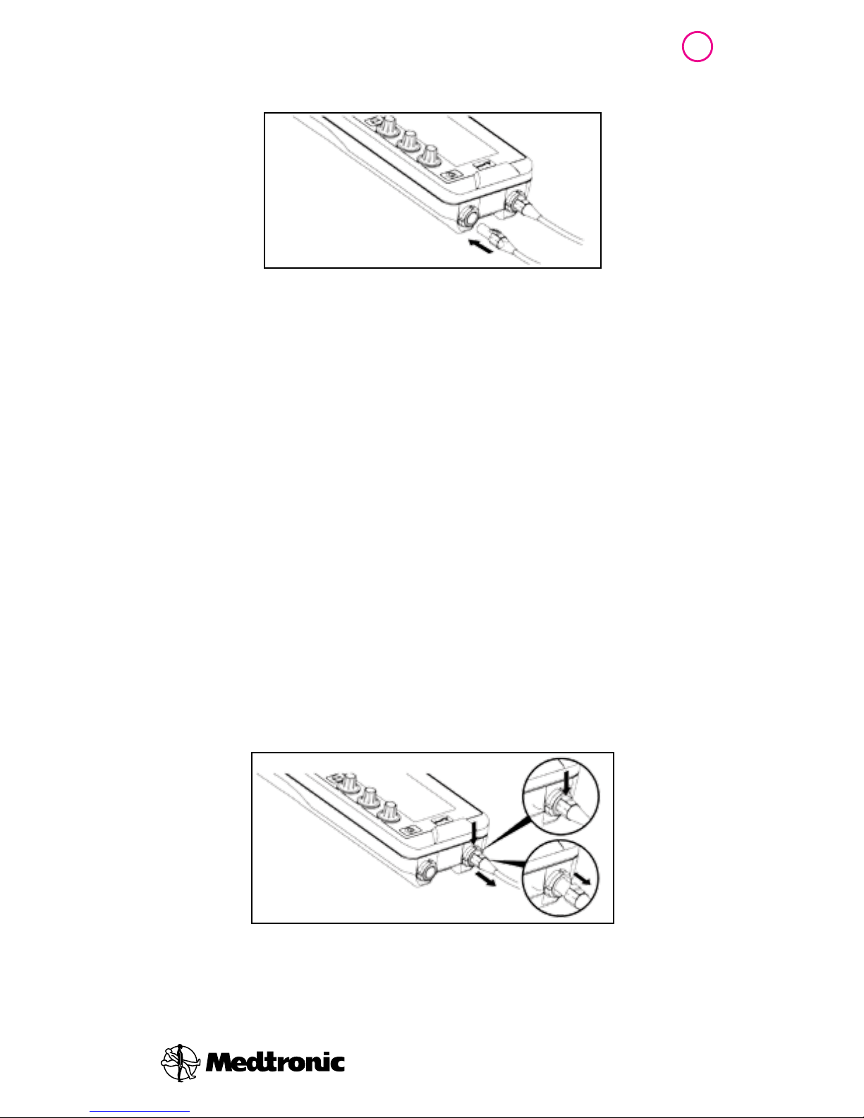
Connector Setup
1. Verify that the temporary pacemaker is turned off.
2. Plug the Model 5433A and Model 5433V patient cables
or a pair of 5832 or 5832S surgical cables into appropriate
sockets on the connector block on top of the temporary
pacemaker. One socket is marked A (atrium); the other is
marked V (ventricle).
3. Verify that each patient cable clicks when it is inserted into
the temporary pacemaker connector receptacle.
Note: The audible click verifies that the plug is completely inserted into
the receptacle.
4. Pull gently on the patient cables after insertion to ensure a
good connection.
5. Connect the leads to the appropriate cable. Match
positive (+) and negative (–) leads to positive (+) and
negative (–) sockets or clips for the atrium and ventricle
(not shown). The sockets are also color-coded blue for
atrium and white for ventricle.
4
Note: To disconnect the patient cables from the temporary pacemaker, do
the following:
1. Press the connector release button on the patient cable plug.
2. Gently pull the plug from the receptacle.
Page 5

Medtronic Model 5392
Basic Operation
To Turn On
• Press and hold the On/Off key momentarily to turn on the
temporary pacemaker
The upper screen and the backlight illuminate, a self-test is
initiated, and the temporary pacemaker first paces, and then
begins sensing and pacing in both chambers (DDD mode).
Note: Pressing a key while the self-test is in process can cause the device
to fail the self-test, and display error code, “0004.” The device may interpret
the pressed key as being “stuck” and, therefore, malfunctioning. If a key is
pressed during the self-test, remove and reinsert the battery to clear the
error code.
To Turn O ff
1. Unlock the temporary pacemaker, if it is locked (see
following section).
2. Press the On/Off key once. A message is displayed in the
lower screen to confirm temporary pacemaker shutdown
(see Figure below).
3. Press the Enter key once to confirm temporary pacemaker
shutdown.
A V
RATE
min-1 ppm
PACE
30 200
SENSE
PACE
SENSE
5
Page 6

UC201205013a EN
Medtronic Model 5392
Basic Operation
Lock/Unlock
The lock/unlock key locks the temporary pacemaker to
prevent inadvertent adjustment of the parameters, or unlocks
the temporary pacemaker when it is locked.
When Locked:
• The Rate, A Output, and V Output parameter values lock
and cannot be adjusted
• Pacing therapy continues to be delivered at the currently
selected values
• The Lock indicator appears in the status bar
• The lower screen does not appear. The Mode Selection
options and pacing parameters cannot be adjusted.
• The pause key is locked
• Press lock/unlock key to unlock the 5392 before adjusting
parameters
• Press lock/unlock key to lock the 5392 after adjusting
parameters
Notes
• The doo/emergency key does not lock. If pressed while the temporary
pacemaker is locked, the temporary pacemaker begins asynchronous
pacing.
• The temporary pacemaker locks under one of the following conditions:
– 60 s after the last parameter adjustment is made
– When the lock/unlock key is pressed
If any parameter dials are adjusted or any keys are pressed while the
temporary pacemaker is locked (other than the
doo/emergency key), the Lock
indicator flashes, and the lower screen displays the Locked message for
approximately 30 s.
6
Page 7
7
Medtronic Model 5392
Basic Operation
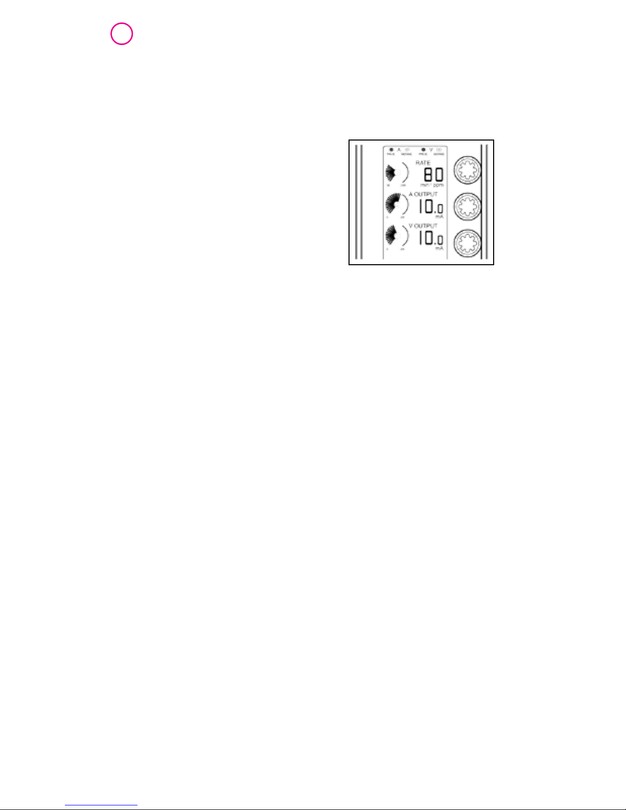
Rate and Output Adjustments
1. If the Lock indicator appears in the status bar, press
lock/unlock key.
2. To adjust rate, a (Atrial) output,
or v (Ventricular) output, turn
the dials clockwise to
increase their values; turn the
dials counterclockwise to
decrease their values, or to
set the outputs to off.
Rate and output values appear on upper screen.
Viewing Patient’s Intrinsic Rhythm
• Reduce the rate gradually, while watching the ECG, until
the patient’s intrinsic rhythm takes over
• Press and hold pause key to suspend pacing and sensing
up to 10 seconds
Note: To pause again up to 10 seconds, release pause key; then press and
hold the pause key again.
EMERGENCY Pacing
• Press doo/emergency key to initiate high-output, dual-
chamber asynchronous pacing (DOO for emergency)
Note: Press the enter key to return to synchronous (demand) pacing, or
select the modes with synchronized pacing from the Mode Selection
menu and adjust A Sensitivity and/or V Sensitivity.
Page 8

UC201205013a EN
Medtronic Model 5392
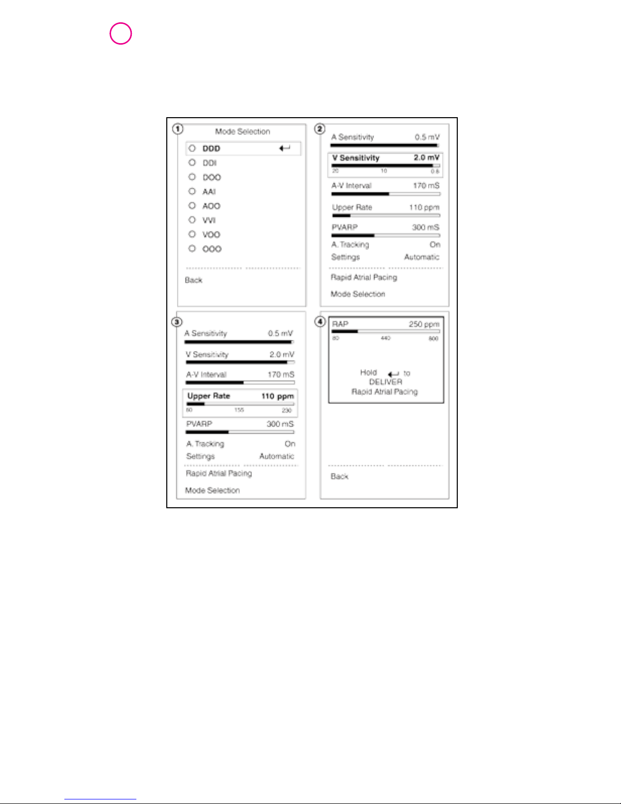
Lower Screen Pacing Parameter Adjustments
After a pacing mode has been selected, the Pacing
Parameters menu for that pacing mode is displayed and
the parameters can be adjusted.
Screen 1: Mode Selection screen
Screen 2: V Sensitivity selected on the DDD pacing
parameters screen
Screen 3: Upper Rate selected on the DDD pacing
parameters screen
Screen 4: RAP screen
Note: Parameters displayed on menus are based on currently
programmed pacing mode and rate. Parameters that do not apply to the
current chambers being paced and sensed are not displayed. Parameters that
did not apply in the previous mode are set to nominal values in the new mode.
8
Page 9

Medtronic Model 5392
Lower Screen Pacing Parameter Adjustments
To Adjust Atrial/Ventricular Sensitivity
1. Press menu key until Menu 1 is displayed.
2. Press select key until A Sensitivity or V Sensitivity is
highlighted.
3. Turn menu parameter dial clockwise to increase sensitivity;
counterclockwise to decrease sensitivity or set to ASYNC.
• A Sensitivity range: 0.4 mV - 10 mV and ASYNC
• V Sensitivity range: 0.8 mV - 20 mV and ASYNC
Notes
• Setting A SENSITIVITY or V SENSITIVITY to ASYNC turns sensing off and
starts asynchronous pacing
• The highest number (in mV) for SENSITIVITY is the least sensitive setting;
the lowest number (in mV) is the most sensitive setting
To Turn Atrial Tracking Off or On
(Set to DDI or DDD mode)
1. Press menu key until Menu 1 is displayed.
2. Press select key until A Tracking is highlighted.
3. Turn menu parameter dial counterclockwise to display OFF
(DDI mode); clockwise to display ON (DDD mode)
Note: Atrial tracking can be set to OFF only from DDD mode and set to
ON only from DDI mode.
9
Page 10

UC201205013a EN
Medtronic Model 5392
Lower Screen Pacing Parameter Adjustments
Rate-Dependent Parameters
Upper Rate, PVARP, and A-V Interval are automatically set
whenever rate is adjusted, but can be manually adjusted
from lower screens.
Note: An asterisk (*) next to the value of each setting that is manually
adjusted.
To Adjust A-V Interval
1. Navigate to the Pacing Parameters menu.
2. Press the up or down arrow key to highlight A-V Interval.
3. Turn the menu parameter dial clockwise to lengthen the
A-V Interval, or counterclockwise to shorten the A-V
Interval.
Range: 20 ms - 300 ms
To Adjust Upper Rate
1. Navigate to the Pacing Parameters menu.
2. Press the up or down arrow key to highlight Upper Rate.
3. Turn the menu parameter dial clockwise to increase the
upper rate, or counterclockwise to decrease the upper
rate. The Upper Rate parameter is only adjustable in
DDD mode.
Range: 80 min-1 - 230 min
-1
10
Page 11

Medtronic Model 5392
Lower Screen Pacing Parameter Adjustments
To Adjust PVARP
1. Navigate to the pacing parameters menu.
2. Press the up or down arrow key to select PVARP.
3. Turn the menu parameter dial clockwise to increase the
PVARP, or counterclockwise to decrease the PVARP.
Range: 150 ms - 500 ms
To Reset Rate-Dependent Values to Automatic Settings
1. Navigate to the pacing parameters menu.
2. Select Settings.
3. Turn the menu parameter dial either clockwise or
counterclockwise until Automatic replaces Manual.
4. Use the menu parameter dial to alternate between
Automatic and Manual parameter settings, as long as
Settings remains selected.
Previous Manual settings are lost when Automatic is selected
for Upper Rate, PVARP, and A-V Interval.
11
Page 12

UC201205013a EN
Medtronic Model 5392
Sensing Thresholds
Note: The sensing threshold is the least sensitive setting at which the
pacemaker can detect a heartbeat. To find the atrial and ventricular
thresholds, monitor the patient’s ECG as you follow the procedure below.
Caution: Pacemaker-dependent patients will have limited or no intrinsic
rate/rhythm.
To Find Atrial or Ventricular Sensing Threshold
1. Turn on the temporary pacemaker without connecting
it to the patient lead system.
Caution: Do not connect the temporary pacemaker to the patient lead
system until step 4.
2. Set Rate to at least 10 min–1 (ppm) under the patient’s
intrinsic rate. This adjustment ensures non-pacing.
3. Adjust the atrial or ventricular output to prevent the risk
of competitive pacing.
• Atrial: Set A Output to 0.1 mA.
• Ventricular: Set V Output to 0.1 mA.
4. Connect the temporary pacemaker to the patient lead
system.
5. Navigate to the mode selection menu and select the
appropriate pacing mode for the patient leads that are
connected to the patient.
• Select DDD mode if both channels are connected
• Select AAI mode if only the atrial channel is connected
• Select VVI mode if only the ventricular channel is
connected
6. Navigate to the Sensitivity settings.
a. Complete steps 7 thru 9 for the A Sensitivity setting,
if the atrial channel is connected.
b. Complete steps 7 thru 9 for the V Sensitivity setting,
if the ventricular channel is connected.
12
Page 13

Medtronic Model 5392
Sensing Thresholds
7. Decrease Sensitivity: Slowly turn the menu parameter dial
counterclockwise (increase mV value) until the sense
indicator stops flashing.
The pace indicator flashes continuously, but capture is not
likely because the output value is set to minimum.
8. Increase Sensitivity: Slowly turn the menu parameter dial
clockwise (decrease mV value) until the sense indicator
starts flashing.
• The pace indicator stops flashing
• This value is the sensing threshold
9. Set Sensitivity to half (or less) the threshold value. This
setting provides at least a 2:1 safety margin.
10. Restore Rate, A Output, or V Output to previous
values.
13
Page 14

UC201205013a EN
Medtronic Model 5392
Stimulation Thresholds
Note: The stimulation threshold is the minimum output pulse needed
to consistently capture the heart. To find this threshold, monitor the ECG
as you follow the procedure below. To reduce the risk of competitive
pacing, find the sensing threshold first (if the patient’s intrinsic rate is
adequate).
To Find Atrial or Ventricular Stimulation Threshold
1. Verify that the patient is connected to the temporary
pacemaker and is being monitored on the ECG.
2. Set Rate at least 10 min–1 (ppm) above the patient’s
intrinsic rate.
This adjustment ensures pacing. The pace indicator flashes.
3. Decrease Output: Slowly turn the output dial
counterclockwise until ECG shows loss of capture.
• Pace and sense indicators flash intermittently.
4. Increase Output: Slowly turn the output dial clockwise
until ECG shows consistent capture.
• The pace indicator flashes continuously; the sense
indicator stops flashing
• This value is the stimulation threshold
5. Set Output to a value at least 2 to 3 times greater than
the stimulation threshold value. This setting provides at
least a 2:1 safety margin.
6. Restore Rate to the previous value.
14
Page 15

Medtronic Model 5392
Pacing Setup
Notes
• The Pacing Setup Table on the other side of this card
provides a reference to output and sensitivity settings for
each available pacing mode.
1. Verify Output.
2. Verify Sensitivity.
3. Verify Atrial Tracking.
4. Verify Pacing Setup Indicators.
• The RAP (Rapid Atrial Pacing) card describes how to
deliver rapid atrial pacing
• The Pacing Parameter Adjustments card describes how to
manually adjust pacing parameters
To Dial-A-Mode (DDD, DDI, DOO, AAI, AOO, VVI, or VOO
pacing modes, or OOO for no pacing therapy)
1. Navigate to the mode selection menu.
2. Press the up or down arrow keys to highlight a pacing mode.
3. Press the enter key select the pacing mode.
Pacing in the selected mode begins as follows:
Rate, Output, and Sensitivity values are set to the nominal
values when a pacing mode is selected, unless they have been
manually adjusted before the pacing mode was selected. If
they have been manually adjusted before the pacing mode
was selected, the new pacing mode retains these values.
Note: Manually-set pacing parameter values are not retained when the
temporary pacemaker is turned off, and then turned back on.
15
Page 16

UC201205013a EN
Temporary External Pacemaker 5392 Setup Table
AOO VOO AAI VVI DOO DDD DDI
Setup Indicators
Instructions
1. Set Output
A Output On Off On Off On On On
V Output Off On Off On On On On
2. Set Sensitivity
A Sensitivity ASYNC NA On NA ASYNC On On
V Sensitivity NA ASYNC NA On ASYNC On On
3. Set
A Tracking NA NA NA NA NA On Off
16
Page 17

Medtronic Model 5392
RAP (Rapid Atrial Pacing)
RAP can be used to interrupt some types of atrial
tachycardias or to induce an atrial tachycardia.
Caution: RAP is for atrial use only. Be sure that the atrial leads are connected
to the atrium, not the ventricle, before enabling RAP.
Caution: RAP may result in tachycardia, acceleration of existing tachycardia,
or fibrillation. Apply high rates under careful patient monitoring and control.
Monitor the patient’s ECG and blood pressure, and ensure that defibrillation
equipment is immediately available.
To Deliver RAP:
1. Navigate to the Pacing Parameters menu.
2. Press the up or down arrow key to highlight Rapid Atrial
Pacing (RAP).
3. Verify that the leads are in contact with the atrium and
are connected to the atrial channel of the temporary
pacemaker through a patient or surgical cable.
4. Press the enter key to open the RAP screen. The RAP screen
displays the RAP rate [initially the rate of 250 min–1 (ppm)].
Pacing continues at currently displayed settings.
5. Adjust RAP rate as needed. Turn the menu parameter dial
clockwise to increase rate, or counterclockwise to decrease
rate.
Note: The range for RAP is 80 min–1 (ppm) to 800 min–1 (ppm).
6. Press and hold the enter key to deliver RAP burst. AOO
pacing begins at displayed RAP rate and current A Output.
The A Pace LED flashes during delivery of RAP pulses.
Note: RAP delivery stops when either the enter key is released, or after 1 min
has passed.
To exit the RAP screen, use the up or down arrow key to select
back, and then press the enter key.
17
Page 18

UC201205013a EN
18
Medtronic Model 5392
RAP (Rapid Atrial Pacing)
Adjusting Rate or Atrial Output during RAP Delivery
The RAP rate and A Output can be adjusted during RAP
delivery by turning the menu parameters dial. To adjust
A Output, do the following:
1. Continue to press and hold the enter key.
2. Turn the menu parameter dial clockwise or counterclockwise
to adjust RAP rate.
3. Turn the a output dial clockwise or counterclockwise to
adjust atrial output.
Resuming Pacing at Previous Settings
• Release enter key to resume pacing at the previous settings.
The temporary pacemaker stops delivering RAP and
resumes operation at the non-RAP settings, within 3 s.
If the A Output is adjusted during RAP, the new setting is
retained when RAP is terminated.
CAUTION: If the temporary pacemaker continues to deliver RAP after the
enter key is released, press the on/off key or the doo/emergency key to stop RAP.
If RAP continues to be delivered, remove the batteries from the temporary
pacemaker. Return the temporary pacemaker for service.
Page 19

Medtronic Model 5392
Battery Replacement
Battery Installation and Replacement
Note: Medtronic recommends disconnecting device from patient before
replacing battery.
1. Press the battery drawer latch release button until the
battery drawer opens.
2. Remove the old batteries.
3. Install two new LR6-sized (AA-sized)
alkaline batteries. Verify that the
batteries align with the polarity
markings on the inside of the
battery drawer.
4. Close the battery drawer firmly until the battery drawer is
fully latched.
Note: Failure to close the battery drawer completely can result in the
battery drawer opening and the temporary pacemaker shutting down.
5. Discard the old batteries properly according to local
regulations.
Notes
• Replace the temporary pacemaker batteries in the following situations:
– Replace the batteries for each new patient
– Replace the batteries when the low battery indicator appears during
temporary pacemaker operation
– Replace the batteries at least once every week when the temporary
pacemaker is in continuous use
• Install the batteries with proper polarity. The temporary pacemaker does
not turn on or provide pacing therapy with incorrect battery polarity
• If during an emergency situation the batteries must be replaced
while the temporary pacemaker is in use, ensure that the temporary
pacemaker is locked before replacing the batteries. Pacing is maintained
at the current settings for 30 s, minimum, if the settings are at nominal
values.
19
Page 20

UC201205013a EN
Page 21

Brief Statement
Model 5392 Dual Chamber Temporary Pacemaker
Product useful life
The expected service life of the temporary pacemaker is five years. Medtronic will not
service or repair the temporary pacemaker after five years. Contact your Medtronic
representative to replace your temporary pacemaker after it has been in service for five
years.
Intended Use: The Medtronic Model 5392 dual chamber temporary pacemaker is intended
to be used in conjunction with a cardiac pacing lead system for temporary single or dual
chamber pacing in a clinical environment by trained personnel. The temporary pacemaker
can be used where short-term demand (synchronous) or asynchronous pacing is indicated
for therapeutic, prophylactic, or diagnostic purposes. The temporary pacemaker must be
used in an environment where the patient is monitored continuously to ensure that it is
operating properly and delivering appropriate therapy to the patient.
Contraindications: There are no known contraindications to the use of temporary pacing
as a means to control the heart rate. The patient’s age and medical condition, however,
may dictate the type of temporary pacemaker and lead system used by the physician.
Pacing modes which allow sensing in the atrium to trigger a ventricular response are
contraindicated in the presence of rapid atrial arrhythmias such as atrial fibrillation or
atrial flutter. Atrial pacing is ineffective in the presence of atrial fibrillation or flutter. Single
chamber atrial pacing is contraindicated in the presence of AV conduction disorders.
Asynchronous pacing is contraindicated in the presence of intrinsic cardiac rhythms. Atrial
high-rate burst pacing therapy is intended for use in the atrium only. High-rate burst pacing
in the ventricle may result in life-threatening arrhythmias. The temporary pacemaker is MR
Unsafe.
Warnings/Precautions: Monitor the patient continuously while the temporary pacemaker
is in use to ensure it is operating properly and delivering appropriate therapy to the patient.
ECG monitoring should be in use and defibrillating equipment should be placed on
standby and be kept immediately available during pacing lead insertion, pulse generator
connection and adjustment, measurements of stimulation thresholds or sensed potentials,
and application of antitachycardia burst therapy. Use of high rates in the atrium may result in
accidental conduction to the ventricle. Defibrillation equipment should be kept immediately
available during high-rate pacing. Operational failure of the temporary pacemaker can occur
as the result of battery depletion, mishandling, or random component failure. Complications
related to the use of temporary external pacemakers such as the Model 5392 include, but
are not limited to, asystole following abrupt cessation of pacing, inhibition, and reversion.
Potential complications related to the use of pacing lead systems with the Model 5392
include, but are not limited to, myocardial irritability resulting in fibrillation, infarction,
pericarditis, rejection, muscle and never stimulation, and infection. Complication related
to inhibition or reversion of the pacemaker in the presence of strong electromagnetic
interference. Whenever possible, for the safety of the patient, disconnect the temporary
pacemaker from the implanted lead system before defibrillating or cardioverting. Excessive
defibrillation energy can damage the temporary pacemaker. This can result in a large current
flowing through the implanted lead system and temporary pacemaker, which could reduce
intended defibrillation energy delivered to the patient or cause myocardial damage. A lead
with extension cable constitutes a direct, low-resistance current path to the myocardium.
During connection and testing procedures, only battery-powered instrumentation should
be used. Extreme caution must be taken to properly ground all line-powered equipment
used in the vicinity of the patient. Electrosurgical units can cause tachyarrhythmias by
inducing current on the leads. Improper connection, displacement or fracture of leads or
cables may result in pacemaker system failure. Inspect leads and cables for damage before
each use. The pacing lead system may cease to function at any time due to improper
connections or lead-related problems such as displacement or fracture. Do not modify the
temporary pacemaker. Modifications could impact the temporary pacemaker effectiveness
and adversely affect patient safety.
See the device manual for detailed information regarding the procedure, indications,
contraindications, warnings, precautions, and potential complications/adverse events. For further
information, please call Medtronic at 1 (800) 328-2518 and/or consult Medtronic’s website at
www.medtronic.com.
Caution: Federal law (USA) restricts this device to sale by or on the order of a physician.
Page 22

World Headquarters
Medtronic, Inc.
710 Medtronic Parkway
Minneapolis, MN 55432-5604
USA
Tel: (763) 514-4000
Fax: (763) 514-4879
Medtronic USA, Inc.
Toll-free: 1 (800) 328-2518
(24-hour technical support for
physicians and medical professionals)
UC201205013a EN © Medtronic, Inc. 2013. Minneapolis, MN. All Rights Reserved. Printed in USA. 09/2013
www.medtronic.com
 Loading...