

Page 1

WarmTouch™
Convective Warming System
Operator's Manual
Page 2

U.S. patents: www.medtronic.com/patents
COVIDIEN, COVIDIEN with logo, and Covidien logo and Positive Results for Life are U.S. and internationally registered trademarks of
Covidien AG. ™* brands are trademarks of their respective owner. Other brands are trademarks of a Covidien company.
Page 3

Symbols
0123
By prescription only (appears on unit and on shipping label)
No free hosing: Hose nozzle must be connected to a WarmTouch™ blanket or thermal injury may occur (appears on
unit only)
Do not use during magnetic resonance imaging (MRI) (appears on unit and on shipping label)
Degree of protection from electric shock: Protection Class I, Type BF applied part (appears on unit only)
Recommendation to consult accompanying documents (appears on unit and on shipping label)
Requirement to consult accompanying documents (appears on unit and on shipping label)
Nature of power supply: Alternating Current (AC) (appears on unit only)
Potential equalization conductor terminal; used to access the warming unit’s electrical ground for electrical safety
testing (appears on unit only)
Universal Serial Bus (USB) port (for service use by qualified personnel only) (appears on unit only)
Keep dry (appears on unit and on shipping label)
Temperature limitations (shipping and storage): -40°C to +70°C (appears on shipping label only)
Temperature limitations (operating): +18°C to +28°C (appears on unit only)
Relative humidity limitations (shipping/storage): 10% to 95% (non-condensing) (appears on shipping label only)
Relative humidity limitations (operating): 15% to 85% (noncondensing) (appears on unit only)
Atmospheric pressure limitations (shipping/storage): 12 kPa to 106 kPa (appears on shipping label only)
Atmospheric pressure limitations (operating): 70 kPa to 106 kPa (appears on unit only)
CE – Conformité Européene authorization mark; 0123 – TÜV SÜD Product Service GmbH (notified body); signifies
compliance with Medical Device Directive 93/42/EEC (appears on unit and on shipping label)
CSA – Canadian Standards Association certification mark (appears on unit only)
European Community (EC) authorized representative (appears on unit and on shipping label)
Serial number (appears on unit and on shipping label)
Catalog number (appears on unit and on shipping label)
Manufacturer (appears on unit and on shipping label)
i
Page 4

Date of manufacture (appears on unit and on shipping label)
Proper waste disposal for electrical and electronic equipment (WEEE) (appears on unit only)
ii
Page 5

Table of Contents
1 Introduction . . . . . . . . . . . . . . . . . . . . . . . . . . . . . . . . . . . . . . . . . . . . . . . . . . . . . . . . . . . . . . . . . . . . . . . . . . . . 5
Overview . . . . . . . . . . . . . . . . . . . . . . . . . . . . . . . . . . . . . . . . . . . . . . . . . . . . . . . . . . . . . . . . . . . . . . . . . . . . 5
Conventions . . . . . . . . . . . . . . . . . . . . . . . . . . . . . . . . . . . . . . . . . . . . . . . . . . . . . . . . . . . . . . . . . . . . . . . . . 5
Safety Information . . . . . . . . . . . . . . . . . . . . . . . . . . . . . . . . . . . . . . . . . . . . . . . . . . . . . . . . . . . . . . . . . . . 5
Obtaining Technical Assistance . . . . . . . . . . . . . . . . . . . . . . . . . . . . . . . . . . . . . . . . . . . . . . . . . . . . . . . 7
Related Documents . . . . . . . . . . . . . . . . . . . . . . . . . . . . . . . . . . . . . . . . . . . . . . . . . . . . . . . . . . . . . . . . . . 9
Warranty Information . . . . . . . . . . . . . . . . . . . . . . . . . . . . . . . . . . . . . . . . . . . . . . . . . . . . . . . . . . . . . . . . 9
2 Product Overview . . . . . . . . . . . . . . . . . . . . . . . . . . . . . . . . . . . . . . . . . . . . . . . . . . . . . . . . . . . . . . . . . . . . 11
Overview . . . . . . . . . . . . . . . . . . . . . . . . . . . . . . . . . . . . . . . . . . . . . . . . . . . . . . . . . . . . . . . . . . . . . . . . . . 11
Product Description . . . . . . . . . . . . . . . . . . . . . . . . . . . . . . . . . . . . . . . . . . . . . . . . . . . . . . . . . . . . . . . . 11
Product Views . . . . . . . . . . . . . . . . . . . . . . . . . . . . . . . . . . . . . . . . . . . . . . . . . . . . . . . . . . . . . . . . . . . . . 13
Operator's Panel . . . . . . . . . . . . . . . . . . . . . . . . . . . . . . . . . . . . . . . . . . . . . . . . . . . . . . . . . . . . . . . . . . . 14
Requirements for Use . . . . . . . . . . . . . . . . . . . . . . . . . . . . . . . . . . . . . . . . . . . . . . . . . . . . . . . . . . . . . . 16
3 Installation . . . . . . . . . . . . . . . . . . . . . . . . . . . . . . . . . . . . . . . . . . . . . . . . . . . . . . . . . . . . . . . . . . . . . . . . . . . 19
Overview . . . . . . . . . . . . . . . . . . . . . . . . . . . . . . . . . . . . . . . . . . . . . . . . . . . . . . . . . . . . . . . . . . . . . . . . . . 19
Safety Reminders . . . . . . . . . . . . . . . . . . . . . . . . . . . . . . . . . . . . . . . . . . . . . . . . . . . . . . . . . . . . . . . . . . 19
Attaching the Power Cord . . . . . . . . . . . . . . . . . . . . . . . . . . . . . . . . . . . . . . . . . . . . . . . . . . . . . . . . . . 19
Installing the Warming Unit . . . . . . . . . . . . . . . . . . . . . . . . . . . . . . . . . . . . . . . . . . . . . . . . . . . . . . . . 20
4 Operation . . . . . . . . . . . . . . . . . . . . . . . . . . . . . . . . . . . . . . . . . . . . . . . . . . . . . . . . . . . . . . . . . . . . . . . . . . . . 27
Overview . . . . . . . . . . . . . . . . . . . . . . . . . . . . . . . . . . . . . . . . . . . . . . . . . . . . . . . . . . . . . . . . . . . . . . . . . . 27
Safety Reminders . . . . . . . . . . . . . . . . . . . . . . . . . . . . . . . . . . . . . . . . . . . . . . . . . . . . . . . . . . . . . . . . . . 27
Positioning the Warming Unit . . . . . . . . . . . . . . . . . . . . . . . . . . . . . . . . . . . . . . . . . . . . . . . . . . . . . . 27
Applying Power . . . . . . . . . . . . . . . . . . . . . . . . . . . . . . . . . . . . . . . . . . . . . . . . . . . . . . . . . . . . . . . . . . . . 29
Overview of Warming Unit Operating Modes . . . . . . . . . . . . . . . . . . . . . . . . . . . . . . . . . . . . . . . 29
Beginning Treatment . . . . . . . . . . . . . . . . . . . . . . . . . . . . . . . . . . . . . . . . . . . . . . . . . . . . . . . . . . . . . . 30
Controlling the Temperature . . . . . . . . . . . . . . . . . . . . . . . . . . . . . . . . . . . . . . . . . . . . . . . . . . . . . . . 32
Powering Off the Warming Unit . . . . . . . . . . . . . . . . . . . . . . . . . . . . . . . . . . . . . . . . . . . . . . . . . . . . 35
Cleaning the Warming Unit after Operation . . . . . . . . . . . . . . . . . . . . . . . . . . . . . . . . . . . . . . . . . 35
5 Maintenance . . . . . . . . . . . . . . . . . . . . . . . . . . . . . . . . . . . . . . . . . . . . . . . . . . . . . . . . . . . . . . . . . . . . . . . . . 37
Overview . . . . . . . . . . . . . . . . . . . . . . . . . . . . . . . . . . . . . . . . . . . . . . . . . . . . . . . . . . . . . . . . . . . . . . . . . . 37
Cleaning the Warming Unit . . . . . . . . . . . . . . . . . . . . . . . . . . . . . . . . . . . . . . . . . . . . . . . . . . . . . . . . 37
Safety Checks . . . . . . . . . . . . . . . . . . . . . . . . . . . . . . . . . . . . . . . . . . . . . . . . . . . . . . . . . . . . . . . . . . . . . . 37
Filter Replacement . . . . . . . . . . . . . . . . . . . . . . . . . . . . . . . . . . . . . . . . . . . . . . . . . . . . . . . . . . . . . . . . . 38
Monitoring the Filter Status . . . . . . . . . . . . . . . . . . . . . . . . . . . . . . . . . . . . . . . . . . . . . . . . . . . . . . . . 38
Component Disposal . . . . . . . . . . . . . . . . . . . . . . . . . . . . . . . . . . . . . . . . . . . . . . . . . . . . . . . . . . . . . . . 39
6 Troubleshooting . . . . . . . . . . . . . . . . . . . . . . . . . . . . . . . . . . . . . . . . . . . . . . . . . . . . . . . . . . . . . . . . . . . . . 41
Overview . . . . . . . . . . . . . . . . . . . . . . . . . . . . . . . . . . . . . . . . . . . . . . . . . . . . . . . . . . . . . . . . . . . . . . . . . . 41
Safety Reminders . . . . . . . . . . . . . . . . . . . . . . . . . . . . . . . . . . . . . . . . . . . . . . . . . . . . . . . . . . . . . . . . . . 41
Problems and Resolutions . . . . . . . . . . . . . . . . . . . . . . . . . . . . . . . . . . . . . . . . . . . . . . . . . . . . . . . . . . 41
Serial Number and System Information . . . . . . . . . . . . . . . . . . . . . . . . . . . . . . . . . . . . . . . . . . . . . 42
7 Alarms . . . . . . . . . . . . . . . . . . . . . . . . . . . . . . . . . . . . . . . . . . . . . . . . . . . . . . . . . . . . . . . . . . . . . . . . . . . . . . . 45
Overview . . . . . . . . . . . . . . . . . . . . . . . . . . . . . . . . . . . . . . . . . . . . . . . . . . . . . . . . . . . . . . . . . . . . . . . . . . 45
If an Alarm Condition Occurs . . . . . . . . . . . . . . . . . . . . . . . . . . . . . . . . . . . . . . . . . . . . . . . . . . . . . . . 45
Pausing Audible Alarms . . . . . . . . . . . . . . . . . . . . . . . . . . . . . . . . . . . . . . . . . . . . . . . . . . . . . . . . . . . . 46
Clearing Alarms . . . . . . . . . . . . . . . . . . . . . . . . . . . . . . . . . . . . . . . . . . . . . . . . . . . . . . . . . . . . . . . . . . . . 47
Operator's Manual English 1
Page 6

8 Product Specifications . . . . . . . . . . . . . . . . . . . . . . . . . . . . . . . . . . . . . . . . . . . . . . . . . . . . . . . . . . . . . . . . 49
Overview . . . . . . . . . . . . . . . . . . . . . . . . . . . . . . . . . . . . . . . . . . . . . . . . . . . . . . . . . . . . . . . . . . . . . . . . . . 49
Physical Characteristics . . . . . . . . . . . . . . . . . . . . . . . . . . . . . . . . . . . . . . . . . . . . . . . . . . . . . . . . . . . . 49
Electrical Requirements . . . . . . . . . . . . . . . . . . . . . . . . . . . . . . . . . . . . . . . . . . . . . . . . . . . . . . . . . . . . 49
Environmental Specifications . . . . . . . . . . . . . . . . . . . . . . . . . . . . . . . . . . . . . . . . . . . . . . . . . . . . . . . 49
Performance Specifications . . . . . . . . . . . . . . . . . . . . . . . . . . . . . . . . . . . . . . . . . . . . . . . . . . . . . . . . 50
Product Compliance . . . . . . . . . . . . . . . . . . . . . . . . . . . . . . . . . . . . . . . . . . . . . . . . . . . . . . . . . . . . . . . 50
Electromagnetic Compatibility (EMC) . . . . . . . . . . . . . . . . . . . . . . . . . . . . . . . . . . . . . . . . . . . . . . . 50
Ground Integrity Test . . . . . . . . . . . . . . . . . . . . . . . . . . . . . . . . . . . . . . . . . . . . . . . . . . . . . . . . . . . . . . 54
Earth Leakage Current Test . . . . . . . . . . . . . . . . . . . . . . . . . . . . . . . . . . . . . . . . . . . . . . . . . . . . . . . . . 54
Enclosure Leakage Current Test . . . . . . . . . . . . . . . . . . . . . . . . . . . . . . . . . . . . . . . . . . . . . . . . . . . . 54
9 Error Codes . . . . . . . . . . . . . . . . . . . . . . . . . . . . . . . . . . . . . . . . . . . . . . . . . . . . . . . . . . . . . . . . . . . . . . . . . . . 57
Overview . . . . . . . . . . . . . . . . . . . . . . . . . . . . . . . . . . . . . . . . . . . . . . . . . . . . . . . . . . . . . . . . . . . . . . . . . . 57
Error Codes and Suggested Resolutions . . . . . . . . . . . . . . . . . . . . . . . . . . . . . . . . . . . . . . . . . . . . 57
Figures
Figure 1. Front View . . . . . . . . . . . . . . . . . . . . . . . . . . . . . . . . . . . . . . . . . . . . . . . . . . . . . . . . . . . . . . . 13
Figure 2. Rear View . . . . . . . . . . . . . . . . . . . . . . . . . . . . . . . . . . . . . . . . . . . . . . . . . . . . . . . . . . . . . . . . 14
Figure 3. Operator's Panel . . . . . . . . . . . . . . . . . . . . . . . . . . . . . . . . . . . . . . . . . . . . . . . . . . . . . . . . . 15
Figure 4. Power Cord Connection . . . . . . . . . . . . . . . . . . . . . . . . . . . . . . . . . . . . . . . . . . . . . . . . . . 19
Figure 5. Power Cord Wrapped and Secured . . . . . . . . . . . . . . . . . . . . . . . . . . . . . . . . . . . . . . . . 20
Figure 6. Rear View . . . . . . . . . . . . . . . . . . . . . . . . . . . . . . . . . . . . . . . . . . . . . . . . . . . . . . . . . . . . . . . . 21
Figure 7. Warming Unit Mounted on IV Pole . . . . . . . . . . . . . . . . . . . . . . . . . . . . . . . . . . . . . . . . 22
Figure 8. Bed Installation . . . . . . . . . . . . . . . . . . . . . . . . . . . . . . . . . . . . . . . . . . . . . . . . . . . . . . . . . . 23
Figure 9. Rear View . . . . . . . . . . . . . . . . . . . . . . . . . . . . . . . . . . . . . . . . . . . . . . . . . . . . . . . . . . . . . . . . 24
Figure 10. Cart Mounting Peg and Warming Unit Mounting Hole . . . . . . . . . . . . . . . . . . . . 24
Figure 11. Warming Unit Mounted on Cart . . . . . . . . . . . . . . . . . . . . . . . . . . . . . . . . . . . . . . . . . 25
Figure 12. Cart Wheel Lock . . . . . . . . . . . . . . . . . . . . . . . . . . . . . . . . . . . . . . . . . . . . . . . . . . . . . . . . . 28
Figure 13. Modes in Operator's Screen . . . . . . . . . . . . . . . . . . . . . . . . . . . . . . . . . . . . . . . . . . . . . 30
Figure 14. Main Screen at Power-On . . . . . . . . . . . . . . . . . . . . . . . . . . . . . . . . . . . . . . . . . . . . . . . 31
Figure 15. Replace Filter Screen at Power-On . . . . . . . . . . . . . . . . . . . . . . . . . . . . . . . . . . . . . . . 31
Figure 16. Warming System Set to 40°C (Medium) . . . . . . . . . . . . . . . . . . . . . . . . . . . . . . . . . . 33
Figure 17. Warming System Set to Boost Mode . . . . . . . . . . . . . . . . . . . . . . . . . . . . . . . . . . . . . 33
Figure 18. Warming System Set to Heat Off . . . . . . . . . . . . . . . . . . . . . . . . . . . . . . . . . . . . . . . . . 34
Figure 19. Warming System Set to Ready Mode . . . . . . . . . . . . . . . . . . . . . . . . . . . . . . . . . . . . . 34
Figure 20. Replace Filter Screen . . . . . . . . . . . . . . . . . . . . . . . . . . . . . . . . . . . . . . . . . . . . . . . . . . . . 38
Figure 21. Menu Screen . . . . . . . . . . . . . . . . . . . . . . . . . . . . . . . . . . . . . . . . . . . . . . . . . . . . . . . . . . . . 39
Figure 22. Filter Information Screen . . . . . . . . . . . . . . . . . . . . . . . . . . . . . . . . . . . . . . . . . . . . . . . . 39
Figure 23. Serial Number Label on Back of Warming Unit . . . . . . . . . . . . . . . . . . . . . . . . . . . 42
Figure 24. Menu Screen . . . . . . . . . . . . . . . . . . . . . . . . . . . . . . . . . . . . . . . . . . . . . . . . . . . . . . . . . . . . 43
Figure 25. System Information Screen . . . . . . . . . . . . . . . . . . . . . . . . . . . . . . . . . . . . . . . . . . . . . . 43
Figure 26. Operator's Panel (Alarm Screen) . . . . . . . . . . . . . . . . . . . . . . . . . . . . . . . . . . . . . . . . . 45
Figure 27. Alarm Screen (Alarm Audio Paused) . . . . . . . . . . . . . . . . . . . . . . . . . . . . . . . . . . . . . 46
Figure 28. Alarm Screen (Alarm Audio Active) . . . . . . . . . . . . . . . . . . . . . . . . . . . . . . . . . . . . . . 47
2 Operator's Manual English
Page 7

Tables
Table 1. Technical Services . . . . . . . . . . . . . . . . . . . . . . . . . . . . . . . . . . . . . . . . . . . . . . . . . . . . . . . . . . . 7
Table 2. Warming System Components and Accessories . . . . . . . . . . . . . . . . . . . . . . . . . . . . 12
Table 3. Device Symbols . . . . . . . . . . . . . . . . . . . . . . . . . . . . . . . . . . . . . . . . . . . . . . . . . . . . . . . . . . . 15
Table 4. Operating Modes . . . . . . . . . . . . . . . . . . . . . . . . . . . . . . . . . . . . . . . . . . . . . . . . . . . . . . . . . 29
Table 5. Temperature Settings . . . . . . . . . . . . . . . . . . . . . . . . . . . . . . . . . . . . . . . . . . . . . . . . . . . . . 32
Table 6. Warming Unit Problems and Resolutions . . . . . . . . . . . . . . . . . . . . . . . . . . . . . . . . . . . 41
Table 7. Alarm Indicators . . . . . . . . . . . . . . . . . . . . . . . . . . . . . . . . . . . . . . . . . . . . . . . . . . . . . . . . . . 45
Table 8. Error Indicators . . . . . . . . . . . . . . . . . . . . . . . . . . . . . . . . . . . . . . . . . . . . . . . . . . . . . . . . . . . . 46
Table 9. Alarm Conditions . . . . . . . . . . . . . . . . . . . . . . . . . . . . . . . . . . . . . . . . . . . . . . . . . . . . . . . . . 46
Table 10. Warming Unit . . . . . . . . . . . . . . . . . . . . . . . . . . . . . . . . . . . . . . . . . . . . . . . . . . . . . . . . . . . . 49
Table 11. Transport Cart (Optional) . . . . . . . . . . . . . . . . . . . . . . . . . . . . . . . . . . . . . . . . . . . . . . . . . 49
Table 12. Electrical Requirements . . . . . . . . . . . . . . . . . . . . . . . . . . . . . . . . . . . . . . . . . . . . . . . . . . 49
Table 13. Operating Specifications . . . . . . . . . . . . . . . . . . . . . . . . . . . . . . . . . . . . . . . . . . . . . . . . . 49
Table 14. Shipping and Storage Specifications . . . . . . . . . . . . . . . . . . . . . . . . . . . . . . . . . . . . . . 49
Table 15. Performance Specifications . . . . . . . . . . . . . . . . . . . . . . . . . . . . . . . . . . . . . . . . . . . . . . . 50
Table 16. Product Compliance . . . . . . . . . . . . . . . . . . . . . . . . . . . . . . . . . . . . . . . . . . . . . . . . . . . . . 50
Table 17. Electromagnetic Emissions Guidelines . . . . . . . . . . . . . . . . . . . . . . . . . . . . . . . . . . . . 51
Table 18. Electromagnetic Immunity Guidelines . . . . . . . . . . . . . . . . . . . . . . . . . . . . . . . . . . . . 51
Table 19. Recommended Separation Distance Calculations . . . . . . . . . . . . . . . . . . . . . . . . . 53
Table 20. Recommended Separation Distances . . . . . . . . . . . . . . . . . . . . . . . . . . . . . . . . . . . . . 54
Table 21. Earth Leakage Current Test . . . . . . . . . . . . . . . . . . . . . . . . . . . . . . . . . . . . . . . . . . . . . . . 54
Table 22. Enclosure Leakage Current Test . . . . . . . . . . . . . . . . . . . . . . . . . . . . . . . . . . . . . . . . . . 54
Table 23. Error Codes and Resolutions . . . . . . . . . . . . . . . . . . . . . . . . . . . . . . . . . . . . . . . . . . . . . . 57
Operator's Manual English 3
Page 8

4 Operator's Manual English
Page 9

1. Introduction
1.1. Overview
This manual contains information for operating the Covidien WarmTouch™ convective
warming system, which consists of the Covidien WarmTouch™ convective warming unit
and associated WarmTouch™ blankets. Before operating the warming system, thoroughly
read this manual. The latest version of this manual is available at:
www.covidien.com
1.2. Conventions
Text and terminology conventions used in this manual include the following items:
•
Warnings alert users to potential serious outcomes (death, injury, or adverse events) to
the patient, user, or environment.
•
Cautions alert users to exercise appropriate care for safe and effective use of the
product.
•
Notes provide additional guidelines or information.
1.3. Safety Information
This section lists all safety information associated with the warming unit.
Where appropriate in the manual, individual warnings and cautions are repeated as
reminders. Please familiarize yourself with this safety information before operating the
warming unit.
1
1.3.1. Warnings
•
Warning: Possible explosion hazard. Do not use the device in the presence of
flammable anesthetics or in an oxygen-rich environment.
•
Warning: Possible electric shock hazard. Grounding reliability can be achieved only
when the warming unit is connected to a suitable mains outlet with protective earth
grounding.
•
Warning: No free-hosing. Keep hose nozzle connected to a WarmTouch™ blanket at all
times or thermal injury may occur.
•
Warning: Possible burn or infection hazard. Do not allow warming blanket to come in
contact with open wounds. All patients’ wounds should be covered while using the
warming system.
•
Warning: Possible patient burns. Use caution and consider discontinuing use on
patients during vascular surgery when an artery to an extremity is clamped. Do not
apply the warming system to ischemic limbs.
•
Warning: Thermal injury may occur if the warming unit hose comes into contact with
the patient.
Operator's Manual English 5
Page 10

•
Warning: Possible fire hazard. Prevent the blanket material from coming into contact
with a laser or an electrosurgical active electrode.
•
Warning: Continuously monitor the patient's temperature during treatment with the
warming system. Use good clinical judgment in selecting and adjusting temperature
settings based on the patient's warming needs and response to treatment.
•
Warning: Using the warming system on patients with transdermal medication patches
may increase the rate of drug delivery, potentially causing harm to the patient.
•
Warning: Thermally conductive materials, such as water, gel, and similar substances,
can decrease the patient's body temperature when the warming unit is switched off.
•
Warning: Do not use the warming system during magnetic resonance imaging (MRI)
scanning.
•
Warning: The use of accessories or cables with the warming system other than those
indicated in this manual may result in non-compliance with the specifications listed
in Electromagnetic Compatibility (EMC), page 50.
•
Warning: Do not operate the warming system in a stacked configuration with other
equipment.
•
Warning: Do not operate the warming system adjacent to other equipment. If such a
configuration cannot be avoided, first test the warming system in the intended
configuration to verify normal operation.
•
Warning: Use WarmTouch™ blankets only as directed. Carefully follow the instructions
for use provided with the blankets regarding proper handling and positioning.
•
Warning: WarmTouch™ blankets are for single patient use only.
•
Warning: Clean the warming unit after each use, as described in Cleaning the Warming
Unit, page 37.
•
Warning: If a fault or sudden change in performance occurs in the warming system,
discontinue use. Notify your sales/service center. The unit must be serviced by qualified
personnel using procedures provided in the service manual.
•
Warning: Possible electrical shock hazard. To reduce the risk of electrical shock, do not
remove the back case. Servicing is only to be done by qualified personnel.
•
Warning: No modification of this equipment is allowed.
1.3.2. Cautions
•
Caution: Federal (U.S.A.) law restricts the use of the warming system to sale by or on
the order of a physician.
•
Caution: Only use WarmTouch™ blankets with the WarmTouch™ warming unit. Do not
attempt to use other types of blankets with the warming unit. Similarly, do not attempt
to use WarmTouch™ blankets with other types of warming units.
•
Caution: Do not spray, pour, or spill any liquid on the warming unit, its accessories,
connectors, switches, or openings in the case.
6 Operator's Manual English
Page 11

•
Caution: The HEPA filter must be replaced every 2,000 hours of operation or 365 days,
whichever comes first. Filter replacement must be performed by qualified personnel.
Refer to the service manual for replacement instructions.
•
Caution: Operation of the warming system may affect or be affected by other devices
in the vicinity due to electromagnetic interference (EMI). If interference occurs, try
increasing the distance between devices, repositioning the cabling, or plugging the
devices into separate outlet circuit branches. See Electromagnetic Compatibility (EMC),
page 50 for additional guidance.
•
Caution: The USB port on the warming unit is for service use by qualified personnel
only. During patient treatment, a USB cable must not be connected to the warming
unit.
•
Caution: The institution should follow local governing ordinances and recycling
instructions regarding disposal or recycling of filter and device components or end of
life of the product.
1.4. Obtaining Technical Assistance
For technical assistance or to order parts and additional manuals, contact Covidien
Technical Services or a local Covidien representative.
1
When contacting Covidien for troubleshooting or service issues, please provide the
information described in Serial Number and System Information, page 42.
Table 1. Technical Services
Covidien Argentina
Aguero 351
Capital Federal - 1171 ABC
Argentina
Tel: (5411) 4863-5300
Fax: (5411) 4863-4142
Covidien Austria GmbH
Campus21
Europaring F09402
Brunn am Gebrige
A-2345 Österreich
Tel: (+43) 2236 - 3788 39
Fax: (+43) 2236 - 3788 3940
Covidien Canada
19600 Clark Graham
Baie d'Urfe, QC, H9X 3R8
Canada
Tel:1-514-695-1220, Ext.4004
Fax: 1-514-695-4965
Covidien Asia
Singapore Regional Service Centre
15 Pioneer Hub, #06-04
Singapore 627753
Tel (65) 6578 5288
Fax (65) 6515 5260
Covidien Belgie S.A.-N.V.
Generaal De Wittelaan 9/5
Mechelen
2800
België
Tel +32 152 981 37
Fax +32 152 167 83
Covidien Chile
Camino lo Boza (Ex 8395)
Pudehuel
Santiago
Chile
Tel: (562) 739 - 3000
Fax: (562) 783 - 3149
Covidien Australia
52A Huntingwood Drive
Huntingwood, NSW 2148
Australia
Tel: (+61) 1800 - 350702
Fax: (+61) 2967 - 18118
Covidien Brazil
Av. Das Nações Undias 12995
Andar 23 - Brooklin
São Paulo, SP
Brasil 04578-000
Tel: (5511) 2187-6200
Fax: (5511) 2187-6380
Covidien China
2F, Tyco Plaza
99 Tian Zhou Rd
Shang Hai 200233
P.R. China
Tel: (+86) 4008 1886 86
Fax: (+86) 2154 4511 18
Operator's Manual English 7
Page 12

Table 1. Technical Services (continued)
Covidien Colombia
Edificio Prados de la Morea
Carretera Central Del Norte
(Cra 7a) Kilometro 18,
Chia-Cundinamarca
Bogota, Colombia
Tel: (571) 619-5469
Fax: (571) 619-5425
Covidien Danmark A/S
Langebrogade 6E, 4. sal
1411 København K
Danmark
Tel +45 702 753 50
Fax +45 702 756 50
Covidien Finland Oy
Läkkisepäntie 23
00620 Helsinki
Finland
Te. +35 896 226 84 10
Fax +35 896 226 84 11
Covidien Hungary
1095 Budapest
Mariassy u. 7
Magyarorszag
Hungary
Tel + 36 1880 7975
Fax + 36 1777 4932
Covidien Israel
5 Shacham St.
North Industrial Park
Caesarea
38900 Israel
Tel +97 246 277 388
Fax +97 266 277 688
Covidien Korea
5F, Hibrand Living Gwan, #215,
Yangjae-Dong,
Seocho-Gu
Seoul, Korea
Tel: +822 570 5459
Fax: +822 570 5499
Covidien Norge AS
Postboks 343
1372 Asker.
Norway
Tel +47 668 522 22
Fax +47 668 522 23
Covidien Costa Rica
Global Park, Parkway 50
La Aurora de Heredia
Costa Rica
Tel: (506) 2239 - 5386
Fax: (506) 2239 - 5319
Covidien Deutschland GmbH
Technisches Service Center
Raffineriestr. 18
93333 Neustadt / Donau
Germany
Tel + 49 944 595 93 80
Fax + 49 944 595 93 65
Covidien France SA
Parc d'affaires Technopolis
Bat. Sigma, 3 Avenue du Canada
LP 851 Les Ulis
91975 Courtaboeuf Cedex
France
Tel +33 169 821 416
Fax +33 169 821 532
Covidien India
10th Floor Building No 9B
DLF Cyber City Phase III Gurgaon
Haryana - 122002
India
Tel + 91 1244 709800
Fax + 91 1244 206850
Covidien Italia S.p.A.
Via Rivoltana 2/D
20090 Segrate
Italy
Tel +39 027 030 81 31
Fax +39 027 031 72 84
Covidien Mexico
Insurgentes Sur # 863, Piso 16
Col. Nápoles
Del. Benito Juarez
Mexico, D.F. 03810 Mexico
Tel: (5255) 5804-1524
Fax: (5255) 5536-1326
Covidien Panama
Parque Industrial Costa del Esta
Calle Primera, Edificio # 109
Panama City, Panama
Tel: (507) 264-7337
Fax: (507) 236-7408
Covidien ECE
Prosecká 851/64
190 00 Praha 9
Česká republika
Tel: +420 239 000 711
Fax: +420 239 000 437
Covidien ECE
Galvaniho 7/a
821 04 Bratislava
Slovakia
Tel.: +421 248 214 573
Fax: +421 248 214 501
Covidien Hong Kong
Unit 12 - 16, 18/F
BEA Tower
Millennium City 5
4187 Kwun Tong Road
Kwun Tong, Kowloon, Hong Kong
Tel + 852 3157 7299
Fax + 852 2838 0749
Covidien Ireland
Block G, Ground Floor,
Cherrywood Technology Park,
Loughlinstown
County Dublin, Ireland
Tel +353 1 4381613
Fax 353 1 439 3039
Covidien Japan Inc.
Technical Support Center
83-1, Takashimadaira 1-Chome
Itabashi-ku, Tokyo 175-0082
Japan
Tel: +81 (0) 3 6859 0120
Fax: +81 (0) 3 6859 0142
Covidien Nederland BV
Hogeweg 105
5301 LL Zaltbommel
Nederland
Tel +31 41 857 66 00
Covidien Polska
Al. Jerozolimskie 162
Warszawa. 02-342
Polska
Tel +48 223 122 130
Fax +48 223 122 020
8 Operator's Manual English
Page 13

Table 1. Technical Services (continued)
Covidien Portugal Lda.
Estrada do Outeiro de Polima,
Lote 10-1° Abóboda
2785-521 S.Domingos de Rana
Portugal
Tel +35 121 448 10 36 /30
Fax +35 121 445 1082
Covidien Saglik A.S.
Maslak Mahallesi Bilim Sokak
No: 5, Sun Plaza Kat: 2-3
Sisli, Istanbul 34398
Turkey
Tel +90 212 366 20 00
Fax +90 212 276 35 25
Covidien Sverige AB
Box 54
171 74 Solna
Sweden
Tel +46 858 56 05 00
Fax + 46 858 56 05 29
Covidien UK
Unit 2, Talisman Business Park
London Road, Bicester
OX26 6HR, United Kingdom
Tel +44(0)1869 328092
Fax +44(0)1869 327585
Covidien Puerto Rico
Palmas Industrial Park
Road 869 Km 2.0 Bldg. #1
Cataño, PR 00962
Tel. 787-993-7250
Ext. 7222 and 7221
Fax 787-993-7234
Covidien South Africa
Corporate Park North
379 Roan Crescent
Randjespark
Midrand, South Africa
Tel +27 115 429 500
Fax +27 115 429 624
Covidien Switzerland
Roosstrasse 53
8832 Wollerau
Schweiz
Tel +41 44786 5050
Fax +41 44786 5010
Covidien US
15 Hampshire Street
Mansfield, MA 02048 USA
Tel 1.800.635.5267
Tel 1.925.463.4635 (toll)
Covidien Russia
53 bld. 5 Dubininskaya Street
Moscow
Russia. 119054
Tel +70 495 933 64 69
Fax +70 495 933 64 68
Covidien Spain S.L.
Business Park World Trade Center
Almeda Park Edificio
7 - 3ª planta Plaça de la Pau s/n
Cornellà de Llobregat
Covidien Thailand
99 Soi Rubia,
Sukhumvit 42 Road
13 - 14 Fl., Berli Jucker Building
Prakanong, Klongtoey
Bangkok 10110, Thailand
Tel +662 2073 - 100
Fax +662 657 - 6325
1
1.5. Related Documents
•
Instructions for Use - Covidien WarmTouch™ Warming Blanket — This document,
provided with WarmTouch™ warming blankets, contains important information
regarding intended use, handling, connection, and positioning of the blanket.
•
Service Manual - Covidien WarmTouch™ Convective Warming Unit — This document,
for use by qualified personnel only, contains instructions for servicing, testing,
updating, and maintaining the warming unit. The service manual also includes
schematics, a parts list, and shipping instructions for factory service.
1.6. Warranty Information
To obtain warranty information, contact Covidien Technical Services or a local Covidien
representative. See Obtaining Technical Assistance, page 7.
Operator's Manual English 9
Page 14

10 Operator's Manual English
Page 15

2. Product Overview
2.1. Overview
This chapter provides an introduction to the Covidien WarmTouch™ convective warming
system, including information about its features, accessories, controls, and requirements
for use.
2.2. Product Description
The warming system provides a means for treating or preventing hypothermia in adult and
pediatric patients in clinical settings. The warming system consists of an electronic blower
(warming unit) that delivers heated air through a flexible hose to a lightweight blanket
placed on the patient. The blanket distributes the heated air through numerous small
perforations that allow the air to reach the targeted areas of the patient’s body.
2.2.1. Features
•
Multiple temperature settings—A range of temperature settings allows the clinician to
customize and adjust treatment based on the patient’s needs.
2
•
Boost mode—For rapid warming, air is generated at 47°C for 45 minutes, after which
the temperature automatically drops to the 45°C (High) temperature setting.
•
HEPA filter—A High Efficiency Particulate Air (HEPA) filter removes at least 99.97% of
particles 0.3 micrometers or larger from the air delivered to the warming blanket. The
warming unit monitors the amount of time the filter is in use and indicates when the
filter needs to be replaced.
•
Automatic over- and under-temperature protection—At any of the heated air settings,
if the temperature of the generated air is out of range for a specific amount of time, the
heater and fan automatically shut off and an alarm is issued.
•
Optional cart with wheel locks—An optional transport cart, equipped with wheel locks,
is available for the warming unit. The wheel locks reduce cart movement while the
system is in use.
2.2.2. Intended Use
The WarmTouch Convective Warming System (warming unit and blanket) is intended for
prevention and treatment of hypothermia, and for the management of appropriate
normothermia.
2.2.3. Contraindications
None known.
2.2.4. Components and Accessories
To order components and accessories, contact Covidien Technical Services or a local
Covidien representative. See Obtaining Technical Assistance, page 7.
Operator's Manual English 11
Page 16

Table 2. Warming System Components and Accessories
Item Description
Covidien WarmTouch™ Convective Warming Unit Electronic blower that delivers heated air to the warming blanket.
Covidien WarmTouch™ warming blankets Warming blankets designed for exclusive use with the warming
unit. Available for a variety of treatment applications.
HEPA filter Replaceable air filter for the warming unit.
Power cord Detachable power cord for the warming unit. Type depends on
country of use.
Transport cart (optional) Optional wheeled cart for mounting the warming unit.
2.2.5. Covidien WarmTouch™ Warming Blankets
The Covidien WarmTouch™ Convective Warming Unit is designed for use with
WarmTouch™ blankets only. WarmTouch™ blankets are designed to attach securely to the
warming unit’s hose nozzle. The nozzle features guides and a clip to ensure correct
orientation.
Do not attempt to use other types of blankets with the warming unit; the performance of
the warming system has not been evaluated with other blankets and cannot be predicted.
The warming unit is compatible with all WarmTouch™ blankets.
Consult the Instructions for Use provided with the warming blankets for important
information regarding proper handling and application.
12 Operator's Manual English
Page 17

2.3. Product Views
2.3.1. Front View
Figure 1. Front View
2
1. Operator's panel
2. Handle
3. No free-hosing label
4. Hose
5. Nozzle strap with clip
6. Nozzle
Operator's Manual English 13
Page 18

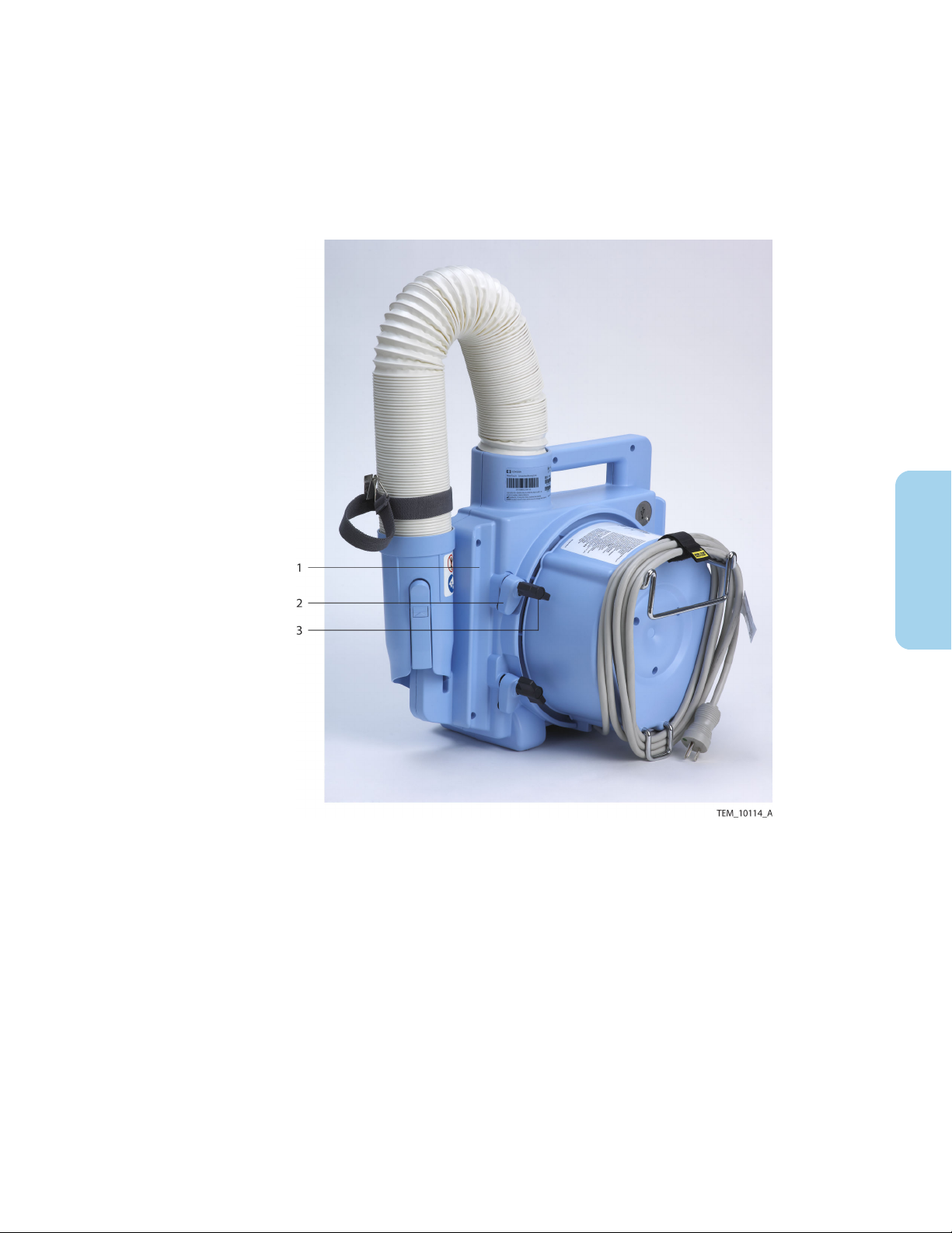
2.3.2. Rear View
Figure 2. Rear View
1. No free-hosing label
2. Serial number label
3. Symbols label
4. USB port (under cover) – for service
use by qualified personnel only
2.4. Operator's Panel
The operator’s panel includes an On/Standby key, a multi-functional keypad, and a display
that provides temperature and status information. The display indicates the function of
each adjacent key.
Note: Key functions change based on operating context, such as when accessing system
information (see Chapter 6), or when an alarm condition is present (see Chapter 7).
14 Operator's Manual English
5. Mounting channel (×2)
6. Blower clamp (×3)
7. Bed hook
8. Power cord
Page 19

Figure 3. Operator's Panel
1. On/Standby Key—Press to place the warming unit in Ready mode or to return to
Standby mode. See Beginning Treatment, page 30 and Returning to Standby
Mode, page 34.
2. Status LED—Indicates the warming unit’s operational status. See Overview of
Warming Unit Operating Modes, page 29.
2
3. Fan Off Key—During operation, press to turn off the fan. The heater, if running,
shuts off automatically. See Returning to Ready Mode, page 34.
4. Temperature and Information Area—Displays the current air temperature being
generated (rounded to the closest 1°C).
5. Menu Key—Press to access screens for viewing filter status and system information.
See Monitoring the Filter Status, page 38 and Serial Number and System
Information, page 42.
6. 47°C (Boost Mode) Key—Press to generate air at 47°C (116.6°F) for 45 minutes.
See Using Boost Mode, page 33.
7. 45°C (High) Key—Press to generate air at 45°C (113°F). See Controlling the
Temperature, page 32.
8. 40°C (Medium) Key—Press to generate air at 40°C (104°F). See Controlling the
Temperature, page 32.
9. 34°C (Low) Key—Press to generate air at 34°C (93.2°F). See Controlling the
Temperature, page 32.
10. Heat Off Key—Press to deliver air at room temperature (unheated). See Controlling
the Temperature, page 32.
Table 3. Device Symbols
Symbol Description
On/standby
Fan off
Menu
Operator's Manual English 15
Page 20

Symbol Description
47°C (Boost Mode)
45°C (High)
40°C (Medium)
34°C (Low)
Heat off
Dashes instead of a temperature reading indicate that the warming unit is in Ready mode (both
heater and fan are off)
Animated symbol indicates that the fan is on.
Animated symbol indicates that the heater is on.
Animated arrow indicates that the temperature is adjusting upward or downward to a new set‐
ting (disappears when the temperature is within 1.5°C of the new setting)
Audio paused symbol (appears on the operator's panel when an alarm is active to denote the
key for pausing audible alarm tones; the symbol color is reversed on the screen while alarm
tones are paused)
Table 3. Device Symbols (continued)
Note: The Menu icon is shown in Figure 3 for reference only; it is accessible only when the
heater and fan are off (Ready mode).
Note: When pressing any of the temperature setting keys, the Heat Off key, or the Fan Off
key, the setting is highlighted on the display to indicate the current selection. For example,
in Figure 3, 34° is the current selection.
Note: A soft click tone indicates a successful key press.
2.5. Requirements for Use
2.5.1. Clinician Prerequisites
The warming system is intended for use by licensed healthcare practitioners or clinical
personnel knowledgeable in its proper operation. Before using the warming system, be
sure to familiarize yourself with the information provided in this manual and in the
instructions for use provided with the warming blankets.
2.5.2. Treatment Environment
•
Warning: Possible explosion hazard. Do not use the device in the presence of
flammable anesthetics or in an oxygen-rich environment.
•
Warning: Do not use the warming system during magnetic resonance imaging (MRI)
scanning.
•
Warning: Do not operate the warming system in a stacked configuration with other
equipment.
16 Operator's Manual English
Page 21

•
Warning: Do not operate the warming system adjacent to other equipment. If such a
configuration cannot be avoided, first test the warming system in the intended
configuration to verify normal operation.
•
Warning: Clean the warming unit after each use, as described in Cleaning the Warming
Unit, page 37.
•
Caution: Do not spray, pour, or spill any liquid on the warming unit, its accessories,
connectors, switches, or openings in the case.
•
Caution: Operation of the warming system may affect or be affected by other devices
in the vicinity due to electromagnetic interference (EMI). If interference occurs, try
increasing the distance between devices, repositioning the cabling, or plugging the
devices into separate outlet circuit branches. See Electromagnetic Compatibility (EMC),
page 50 for additional guidance.
The warming system is intended for use only in hospitals and hospital-type facilities.
Typical locations of use include the operating room, the operative holding area, the post
anesthesia care unit (PACU), and other care areas. The warming system is not intended for
home use.
Proper operation of the warming system requires the following conditions:
•
Ambient temperature: 18°C to 28°C (64.4°F to 82.4°F)
2
•
Relative humidity: 15% to 85% (non-condensing)
2.5.3. Warming Blanket Use
•
Warning: No free-hosing. Keep hose nozzle connected to a WarmTouch™ blanket at all
times or thermal injury may occur.
•
Warning: Possible fire hazard. Prevent the blanket material from coming into contact
with a laser or an electrosurgical active electrode.
•
Warning: Use WarmTouch™ blankets only as directed. Carefully follow the instructions
for use provided with the blankets regarding proper handling and positioning.
•
Warning: WarmTouch™ blankets are for single patient use only.
•
Caution: Only use WarmTouch™ blankets with the WarmTouch™ warming unit. Do not
attempt to use other types of blankets with the warming unit. Similarly, do not attempt
to use WarmTouch™ blankets with other types of warming units.
2.5.4. Patient Considerations
•
Warning: Possible burn or infection hazard. Do not allow warming blanket to come in
contact with open wounds. All patients’ wounds should be covered while using the
warming system.
•
Warning: Possible patient burns. Use caution and consider discontinuing use on
patients during vascular surgery when an artery to an extremity is clamped. Do not
apply the warming system to ischemic limbs.
•
Warning: Thermal injury may occur if the warming unit hose comes into contact with
the patient.
Operator's Manual English 17
Page 22

•
Warning: Continuously monitor the patient's temperature during treatment with the
warming system. Use good clinical judgment in selecting and adjusting temperature
settings based on the patient's warming needs and response to treatment.
•
Warning: Using the warming system on patients with transdermal medication patches
may increase the rate of drug delivery, potentially causing harm to the patient.
•
Warning: Thermally conductive materials, such as water, gel, and similar substances,
can decrease the patient's body temperature when the warming unit is switched off.
18 Operator's Manual English
Page 23

3. Installation
3.1. Overview
This chapter contains information for installing the Covidien WarmTouch™ convective
warming unit.
3.2. Safety Reminders
Warning: The use of accessories or cables with the warming system other than those
indicated in this manual may result in non-compliance with the specifications listed
in Electromagnetic Compatibility (EMC), page 50.
Warning: No modification of this equipment is allowed.
3.3. Attaching the Power Cord
The warming unit is shipped with a power cord appropriate to the country of use.
To attach the power cord:
1. Position the warming unit on its front so the bottom of the unit is accessible.
2. Connect the power cord’s female connector to the socket in the warming unit,
making sure the connector is fully inserted.
Figure 4. Power Cord Connection
3
1. Power cord female connector
3. Press the power cord into the routing bracket until it is fully seated.
2. Routing bracket
Operator's Manual English 19
Page 24
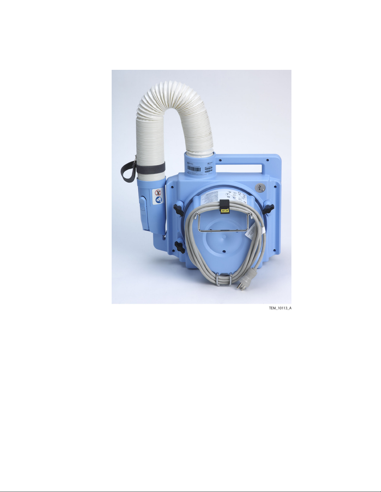
4. Set the warming unit upright. Wrap the power cord around the back of the unit,
and secure it with the provided strap. See Figure 5.
Figure 5. Power Cord Wrapped and Secured
3.4. Installing the Warming Unit
The warming unit can be used as a standalone device, or it can be mounted on an IV pole,
bed, or optional transport cart. The following sections provide mounting instructions.
3.4.1. IV Pole Installation
The warming unit can be mounted on an IV pole with a maximum diameter of 3.2 cm (1.25
inches) and a minimum diameter of 1.9 cm (0.75 inches).
To avoid tipping, the warming unit must be mounted on the pole with the handle no
higher than 76 cm (30 inches) above the floor.
Tools Required: Measuring tape
To install the warming unit on an IV pole:
1. On the IV pole, mark the maximum mounting height. The warming unit’s handle
must be no higher than 76 cm (30 inches) above the floor.
20 Operator's Manual English
Page 25
2. Ensure that the power cord is secured at the back of the warming unit. See Figure 5.
3. Locate the mounting channel with two clamps at the back of the warming unit. Do
not use the mounting channel with one clamp. See Figure 6.
4. Loosen the knobs on the two clamps and rotate the clamp feet away from the
mounting channel.
Figure 6. Rear View
1. Mounting channel
2. Clamp foot (×2)
5. Bracing the IV pole, position the warming unit against the pole so that the pole is
fully seated in the mounting channel. Verify that the handle is not above the
maximum height. See Figure 7.
6. Rotate the two clamp feet across the IV pole, and tighten the clamp knobs to
secure the warming unit. Do not overtighten.
3. Clamp knob (×2)
3
Operator's Manual English 21
Page 26

Figure 7. Warming Unit Mounted on IV Pole
3.4.2. Bed Installation
The warming unit can be attached to a bed that has a mounting surface up to 3.6 cm (1.4
inches) wide. Typically, the unit is attached to the bed’s head board or foot board.
Tools Required: None
To attach the warming unit to a bed:
1. Locate the bed hook on the back of the warming unit. See Figure 2, page 14. The
hook slides in and out to accommodate different mounting surface widths.
2. Hang the bed hook over the mounting surface to attach the warming unit to the
bed.
22 Operator's Manual English
Page 27

Figure 8. Bed Installation
3.4.3. Cart Installation
An optional transport cart is available for the warming unit. Contact Covidien Technical
Services or a local Covidien representative to purchase the transport cart. See Obtaining
Technical Assistance, page 7.
Tools Required: None
To install the warming unit on the cart:
1. Ensure that the power cord is secured at the back of the warming unit. See Figure 9.
2. Loosen the knobs on the three clamps at the back of the warming unit, and rotate
the clamp feet away from the mounting channels.
3
Operator's Manual English 23
Page 28

Figure 9. Rear View
1. Mounting channel (×2)
3. Clamp foot (×3)
2. Clamp knob (×3)
3. Locate the mounting pegs on the cart’s vertical poles, and locate the holes at the
bottom of the warming unit’s mounting channels.
Figure 10. Cart Mounting Peg and Warming Unit Mounting Hole
1. Mounting channel (×2)
2. Mounting hole (×2)
24 Operator's Manual English
3. Mounting peg (×2)
Page 29

4. Holding the warming unit by the handle and bracing the cart, position the
warming unit against the cart so that the mounting holes engage the mounting
pegs. The cart poles must be fully seated in the mounting channels.
5. Rotate each of the three clamp feet across the cart poles, and tighten the clamp
knobs to secure the warming unit. Do not overtighten.
Figure 11. Warming Unit Mounted on Cart
3
Operator's Manual English 25
Page 30

26 Operator's Manual English
Page 31

4. Operation
4.1. Overview
This chapter provides instructions for operating the Covidien WarmTouch™ convective
warming unit. Use these instructions in conjunction with the instructions for use provided
with WarmTouch™ warming blankets.
4.2. Safety Reminders
•
Warning: The use of accessories or cables with the warming system other than those
indicated in this manual may result in non-compliance with the specifications listed
in Electromagnetic Compatibility (EMC), page 50.
•
Warning: Clean the warming unit after each use, as described in Cleaning the Warming
Unit, page 37.
•
Warning: If a fault or sudden change in performance occurs in the warming system,
discontinue use. Notify your sales/service center. The unit must be serviced by qualified
personnel using procedures provided in the service manual.
•
Caution: Federal (U.S.A.) law restricts the use of the warming system to sale by or on
the order of a physician.
•
Caution: Only use WarmTouch™ blankets with the WarmTouch™ warming unit. Do not
attempt to use other types of blankets with the warming unit. Similarly, do not attempt
to use WarmTouch™ blankets with other types of warming units.
•
Caution: The HEPA filter must be replaced every 2,000 hours of operation or 365 days,
whichever comes first. Filter replacement must be performed by qualified personnel.
Refer to the service manual for replacement instructions.
•
Caution: The USB port on the warming unit is for service use by qualified personnel
only. During patient treatment, a USB cable must not be connected to the warming
unit.
4.3. Positioning the Warming Unit
•
Warning: Do not operate the warming system in a stacked configuration with other
equipment.
•
Warning: Do not operate the warming system adjacent to other equipment. If such a
configuration cannot be avoided, first test the warming system in the intended
configuration to verify normal operation.
As described in Chapter 3, the warming unit may be mounted on a cart, IV pole, or bed.
Alternatively, the warming unit can be placed on the floor (under the operating table, for
example). Whichever method is used, be sure to consider the following when positioning
the warming unit for operation:
4
Operator's Manual English 27
Page 32
•
Power outlet access and power cord position—Ensure that the power outlet used for
the warming unit is easily accessible; disconnection from the outlet is the only way to
completely remove power from the warming unit.
•
Air intake clearance—Ensure that the air intake at the back of the warming unit is not
obstructed. Do not cover any part of the warming unit.
•
Front panel access and visibility—Ensure that the operator can easily access the
warming unit’s front panel controls and view the display during treatment.
•
Hose position—Determine where the warming unit hose will be connected to the
blanket. Ensure that the hose does not impede access to the patient, warming unit
controls, or other equipment. To secure the hose, use the clip attached to the nozzle
strap (see Figure 1, page 13).
•
Sterility—Certain WarmTouch™ blankets intended for surgical applications are sterile
when used according to their instructions, while the warming unit and hose are not
sterile. Check the blanket before use to see if it is a sterile blanket. If the blanket is
sterile, to maintain a sterile operating field, position the warming unit and hose outside
the sterile field. To maintain sterility for sterile blankets, carefully follow the blanket’s
instructions for use.
Prior to operation, check the warming unit, power cord, and safety labels for any damage
or deterioration. If service is required, contact Covidien Technical Services or a local
Covidien representative. See Obtaining Technical Assistance, page 7.
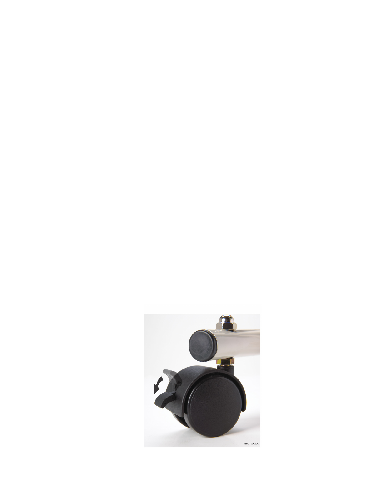
4.3.1. Using the Optional Transport Cart
If the warming unit is mounted on the optional cart, engage the two rear wheel locks to
reduce cart movement during use. Press the lock arms down to lock the wheels
(see Figure 12). Lift the lock arms up to move the cart.
Figure 12. Cart Wheel Lock
28 Operator's Manual English
Page 33

4.4. Applying Power
•
Warning: Possible explosion hazard. Do not use the device in the presence of
flammable anesthetics or in an oxygen-rich environment.
•
Warning: Possible electric shock hazard. Grounding reliability can be achieved only
when the warming unit is connected to a suitable mains outlet with protective earth
grounding.
•
Warning: Do not use the warming system during magnetic resonance imaging (MRI)
scanning.
•
Caution: Operation of the warming system may affect or be affected by other devices
in the vicinity due to electromagnetic interference (EMI). If interference occurs, try
increasing the distance between devices, repositioning the cabling, or plugging the
devices into separate outlet circuit branches. See Electromagnetic Compatibility (EMC),
page 50 for additional guidance.
To apply power to the warming unit:
1. Ensure that you have followed the guidelines in Positioning the Warming Unit,
page 27.
2. Plug the warming unit’s power cord into a hospital-grade or suitable mains outlet
with protective earth grounding.
The status LED illuminates amber to indicate that the warming unit is in Standby mode. The
fan and heater are off, and the display is blank.
4.5. Overview of Warming Unit Operating Modes
Table 4. Operating Modes
Standby mode Ready mode Treatment mode
Status LED Amber Green Green
Heater Off Off On or Off
Fan Off Off On
Display Off On On
4
Operator's Manual English 29
Page 34
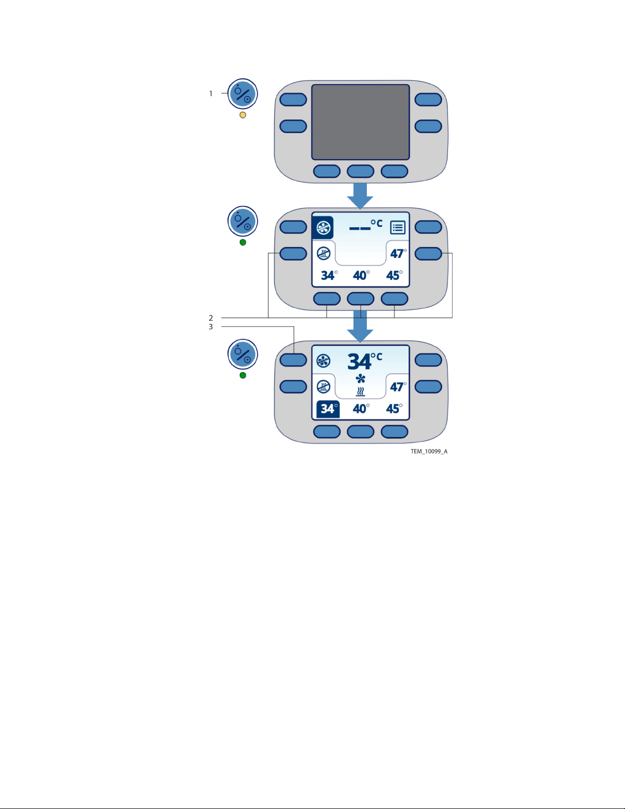
Figure 13. Modes in Operator's Screen
1. On/Standby Key—Press to place the unit in Ready mode and prepare for operation,
or press to return to Standby mode when treatment is complete. See Beginning
Treatment, page 30 and Returning to Standby Mode, page 34.
2. Temperature Keys—Press to place the unit in Treatment mode, delivering air to the
blanket. See Controlling the Temperature, page 32.
3. Fan Off Key—Press to return to Ready mode, pausing air delivery during treatment.
See Returning to Standby Mode, page 34.
4.6. Beginning Treatment
•
Warning: No free-hosing. Keep hose nozzle connected to a WarmTouch™ blanket at all
times or thermal injury may occur.
•
Warning: Possible burn or infection hazard. Do not allow warming blanket to come in
contact with open wounds. All patients’ wounds should be covered while using the
warming system.
•
Warning: Thermal injury may occur if the warming unit hose comes into contact with
the patient.
30 Operator's Manual English
Page 35
•
Warning: Using the warming system on patients with transdermal medication patches
may increase the rate of drug delivery, potentially causing harm to the patient.
•
Warning: Thermally conductive materials, such as water, gel, and similar substances,
can decrease the patient's body temperature when the warming unit is switched off.
•
Warning: Use WarmTouch™ blankets only as directed. Carefully follow the instructions
for use provided with the blankets regarding proper handling and positioning.
•
Warning: WarmTouch™ blankets are for single patient use only.
•
Caution: Do not spray, pour, or spill any liquid on the warming unit, its accessories,
connectors, switches, or openings in the case.
To begin treatment:
1.
Press the On/Standby key. The unit enters Ready mode.
•
The status LED turns green, and the display turns on.
•
A short tone indicates a successful power-on self-test (POST). If POST is
unsuccessful, an alarm screen appears. See If an Alarm Condition Occurs,
page 45.
•
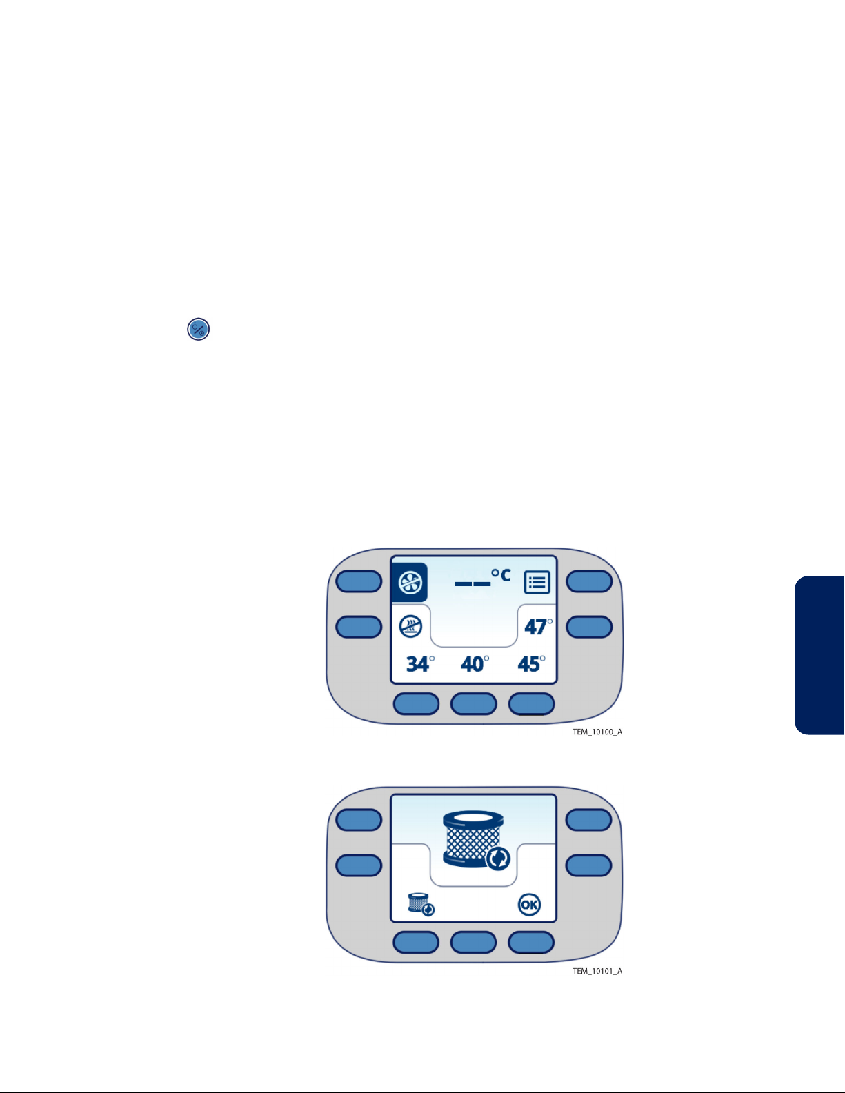
The Main screen appears (Figure 14). Note that if the filter needs to be
replaced, the Replace Filter screen appears instead of the Main screen
(Figure 15).
Figure 14. Main Screen at Power-On
4
Figure 15. Replace Filter Screen at Power-On
2. If the Replace Filter screen appears, take the warming unit out of operation and
have the filter replaced by qualified personnel (see Filter Replacement, page 38). It
Operator's Manual English 31
Page 36

is possible to continue operation; however, failure to replace the filter as
recommended can adversely affect device performance. If you choose to continue
operation, press the OK key. The Main screen appears (Figure 14). Until the filter is
replaced, the Replace Filter screen reappears at each subsequent power-on.
3. Position a WarmTouch™ warming blanket on the patient, and attach the blanket to
the hose, as described in the blanket’s instructions for use. Make sure that the hose
is positioned such that it does not twist the blanket inlet.
4. Proceed to Controlling the Temperature, page 32 to select a temperature setting
for the patient.
4.7. Controlling the Temperature
•
Warning: No free-hosing. Keep hose nozzle connected to a WarmTouch™ blanket at all
times or thermal injury may occur.
•
Warning: Possible patient burns. Use caution and consider discontinuing use on
patients during vascular surgery when an artery to an extremity is clamped. Do not
apply the warming system to ischemic limbs.
•
Warning: Possible fire hazard. Prevent the blanket material from coming into contact
with a laser or an electrosurgical active electrode.
•
Warning: Continuously monitor the patient's temperature during treatment with the
warming system. Use good clinical judgment in selecting and adjusting temperature
settings based on the patient's warming needs and response to treatment.
•
Caution: Do not spray, pour, or spill any liquid on the warming unit, its accessories,
connectors, switches, or openings in the case.
Select an initial setting by pressing one of the temperature keys. Continuously monitor the
patient’s temperature, and adjust the setting as necessary.
Note that the temperature settings and readings on the display correspond to internal
measurements of the air entering the hose. The air temperature entering the blanket is
lower and can vary depending on environmental conditions. Use Table 5 as a guideline for
selecting temperature settings.
Table 5. Temperature Settings
Setting Average temperature entering
hose
(Heat Off)
(Low)
(Medium)
(High)
(Boost)
Room temperature Room temperature To aid in cooling the patient,
34°C (93°F) 32°C (90°F) To help prevent or treat
40°C (104°F) 38°C (100°F)
45°C (113°F) 42°C (108°F)
47°C (117°F) for 45 minutes 44°C (111°F) To rapidly warm patients.
Average temperature entering
blanket
Typical use
if necessary.
hypothermia, or to maintain
appropriate normothermia.
32 Operator's Manual English
Page 37
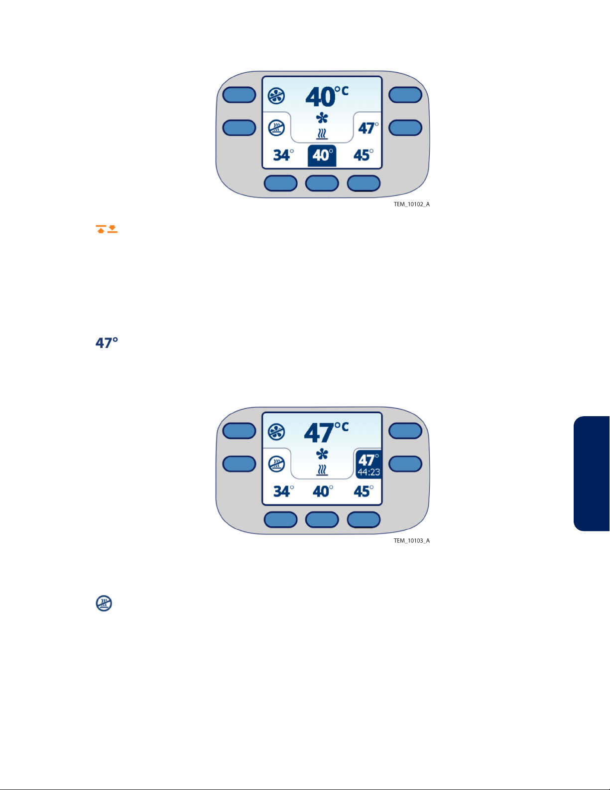
Figure 16. Warming System Set to 40°C (Medium)
When changing the temperature setting, an amber arrow appears next to the current
temperature while it adjusts. When the temperature is within approximately 1.5°C of the
new setting, the arrow disappears.
4.7.1. Using Boost Mode
Boost mode allows rapid warming of patients. Air is generated at 47°C (116.6°F) for 45
minutes. After 45 minutes, the setting automatically changes to 45°C (High).
To use Boost mode, press the 47°C (Boost Mode) key. A countdown timer shows the
time remaining before the temperature switches to the 45°C (High) setting. Boost mode
sessions can be repeated as necessary.
Figure 17. Warming System Set to Boost Mode
4.7.2. Using the Heat Off Setting
If a patient requires cooling, press the Heat Off key. Air is delivered to the warming
blanket at room temperature (heater off).
4
Operator's Manual English 33
Page 38
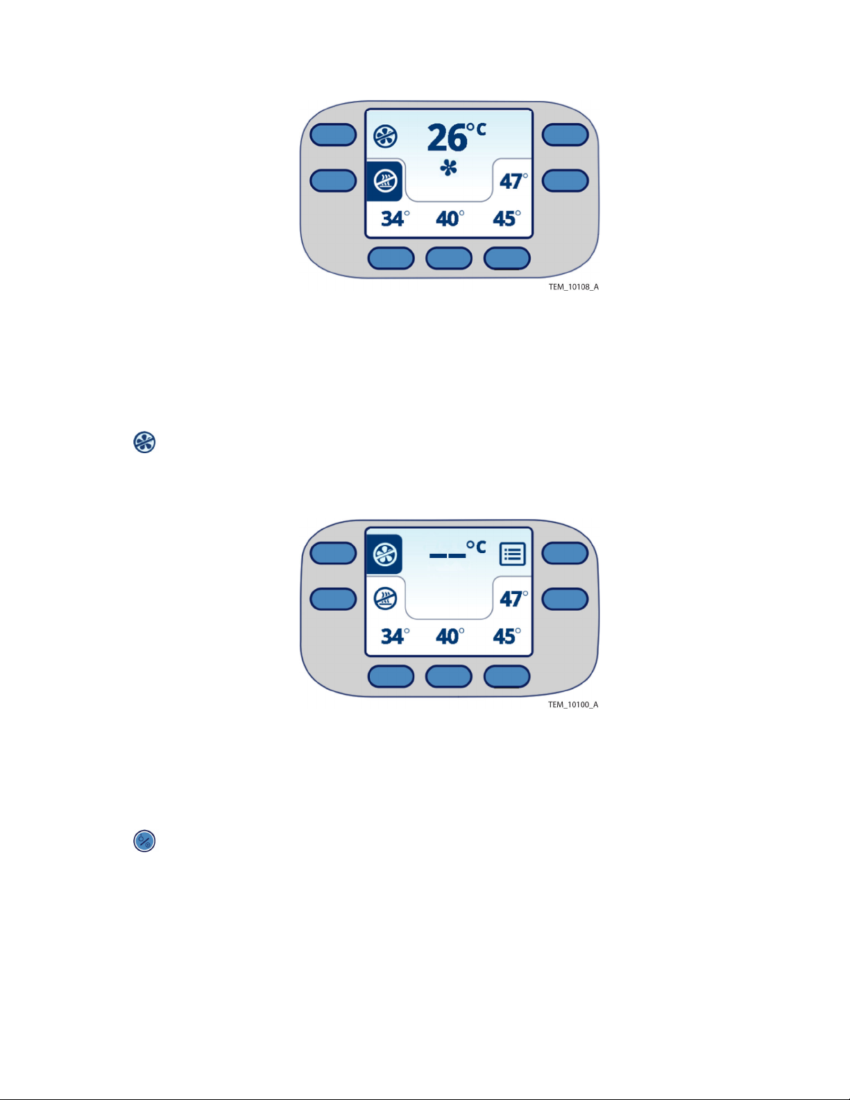
Figure 18. Warming System Set to Heat Off
4.7.3. Returning to Ready Mode
During operation, you can switch back to Ready mode (fan and heat off) any time you do
not need to apply air to the warming blanket. The display stays on, and the unit remains
ready to operate.
To return to Ready mode, press the Fan Off key. Note that in Ready mode, the
temperature reading shows dashes.
Figure 19. Warming System Set to Ready Mode
4.7.4. Returning to Standby Mode
Use Standby mode when you are finished using the warming system but do not wish to
unplug it.
To return to Standby mode during operation, press the On/Standby key. The heater
and fan shut off, the display goes blank, and the status LED turns amber.
4.7.5. If Power is Interrupted
If power is interrupted during operation, the warming unit responds as follows, based on
the duration of the power loss:
•
Power restored within approximately 15 seconds—The warming unit powers up,
performs a power-on self-test (POST), and resumes operation in the same mode as
before the power loss.
34 Operator's Manual English
Page 39

•
Power restored after approximately 15 seconds—The warming unit powers up in
Standby mode.
If the warming unit powers back up in Standby mode, press the On/Standby key to
enter Ready mode, then select a temperature setting to resume treatment.
4.8. Powering Off the Warming Unit
To power off the warming unit:
1. Press the On/Standby key. The fan and heater (if running at the time) turn off.
The display goes blank, and the status LED turns amber.
2. To completely remove power from the warming unit, unplug the unit’s power cord
from the outlet.
4.9. Cleaning the Warming Unit after Operation
Warning: Clean the warming unit after each use, as described in this manual. See Cleaning
the Warming Unit, page 37.
To reduce the risk of patient or operator infection, clean the warming unit after each use.
Operator's Manual English 35
4
Page 40

36 Operator's Manual English
Page 41

5. Maintenance
5.1. Overview
This chapter describes the cleaning and maintenance requirements for the Covidien
WarmTouch™ convective warming unit.
5.2. Cleaning the Warming Unit
Warning: Clean the warming unit after each use, as described in this manual.
Caution: Do not spray, pour, or spill any liquid on the warming unit, its accessories,
connectors, switches, or openings in the case.
For surface cleaning and disinfection of the warming unit, follow your institution's
procedures or the recommended actions below:
•
Surface cleaning—Use a soft cloth dampened with either a commercial, nonabrasive
cleaner or a solution of 70% alcohol in water, lightly wiping the surfaces of the
warming unit.
•
Disinfection—Use a soft cloth saturated with a solution of 10% chlorine bleach in tap
water, lightly wiping the surfaces of the warming unit.
5.3. Safety Checks
5.3.1. Physical Inspection
Covidien recommends a visual check of the following items before each use of the
warming unit:
•
Equipment—Inspect the warming unit and power cord for mechanical damage or
deterioration.
•
Labels—Inspect the safety labels for legibility.
Do not use a damaged unit. If service is required, contact Covidien Technical Services or a
local Covidien representative. See Obtaining Technical Assistance, page 7.
5.3.2. Alarm and Temperature Verification
Once a year, qualified personnel must perform tests to verify the alarm system and the
heater’s output temperatures. Instructions are provided in the service manual. Covidien
recommends performing these tests each time the filter is replaced and any time the unit
requires repair.
5.3.3. Electrical Safety Tests
5
Electrical safety tests must be performed by qualified personnel after specific types of
service. Consult the service manual for requirements and instructions.
Operator's Manual English 37
Page 42

5.4. Filter Replacement
Caution: The HEPA filter must be replaced every 2,000 hours of operation or 365 days,
whichever comes first. Filter replacement must be performed by qualified personnel. Refer
to the service manual for replacement instructions.
If the filter needs to be replaced, the screen shown in Figure 20 appears at power-on.
Remove the warming unit from operation until the filter can be replaced by qualified
personnel. Failure to replace the filter as recommended can adversely affect device
performance.
Figure 20. Replace Filter Screen
5.5. Monitoring the Filter Status
The warming unit monitors filter usage and provides counters that indicate the number of
operating hours and days until the filter needs to be replaced. Anticipate filter replacement
by checking the counters on the Filter Information screen.
Note: The Filter Information screen is only accessible when the warming unit is in Ready
mode. It is not accessible while the warming unit is operating.
To view the Filter Information screen:
1. If the warming unit is not already powered on, follow the steps in Applying Power,
page 29.
2.
3. Press the Menu key on the Main screen. The Menu screen appears.
Press the On/Standby key to enter Ready mode.
38 Operator's Manual English
Page 43

Figure 21. Menu Screen
4. Press the Filter Information key. The Filter Information screen indicates the
days and operating hours remaining before the filter needs to be replaced.
Figure 22. Filter Information Screen
1. Filter Days Remaining 2. Filter Hours Remaining
5. To return to the Main screen, press the Exit key twice.
Note: The Menu screen and Filter Information screen shown in Figure 21 and Figure 22
provide access to service functions used by qualified personnel only. These functions
require input of a key code. Press the Exit key to return to the prior screen after
inadvertently pressing either of these keys:
System Test key
Filter Reset key
5.6. Component Disposal
Caution: The institution should follow local governing ordinances and recycling
instructions regarding disposal or recycling of filter and device components or end of life of
the product.
Instructions for the proper disposal of used warming blankets are provided in the blanket’s
instructions for use.
Air filter replacement and disposal must be performed by qualified personnel. Instructions
for the proper disposal of used filters are provided in the service manual.
5
Operator's Manual English 39
Page 44

The warming unit must be disposed of in accordance with WEEE Directive and
national laws and regulations. Do not dispose of this product as unsorted municipal waste.
40 Operator's Manual English
Page 45

6. Troubleshooting
6.1. Overview
This chapter describes how to troubleshoot problems that may occur while using the
Covidien WarmTouch™ convective warming unit.
6.2. Safety Reminders
•
Warning: If a fault or sudden change in performance occurs in the warming system,
discontinue use. Notify your sales/service center. The unit must be serviced by qualified
personnel using procedures provided in the service manual.
•
Warning: Possible electrical shock hazard. To reduce the risk of electrical shock, do not
remove the back case. Servicing is only to be done by qualified personnel.
•
Warning: No modification of this equipment is allowed.
•
Caution: Operation of the warming system may affect or be affected by other devices
in the vicinity due to electromagnetic interference (EMI). If interference occurs, try
increasing the distance between devices, repositioning the cabling, or plugging the
devices into separate outlet circuit branches. See Electromagnetic Compatibility (EMC),
page 50 for additional guidance.
6.3. Problems and Resolutions
Table 6. Warming Unit Problems and Resolutions
Problem Resolution
Failure to power on Check the power cord’s connection to the warming unit. The connector
must be fully seated. See Attaching the Power Cord, page 19.
If the power cord is properly connected, an internal component may have
failed. Notify qualified personnel to service the warming unit.
Electromagnetic interference between the
warming unit and other devices
Filter needs to be replaced Remove the warming unit from operation and have the filter replaced by
Low-priority alarm Power the warming unit off and back on to clear the alarm.
Software error Power the warming unit off and back on to clear the error.
Try increasing the distance between devices, repositioning the cabling, or
plugging the devices into separate outlet circuit branches.
See Electromagnetic Compatibility (EMC), page 50 for additional guid‐
ance.
qualified personnel. See Filter Replacement, page 38.
Failure to replace the filter as recommended can adversely affect device
performance.
See If an Alarm Condition Occurs, page 45 for additional information.
See Chapter 9 for additional information.
Operator's Manual English 41
6
Page 46

6.4. Serial Number and System Information
If needing to contact Covidien Technical Services for assistance, please provide the
warming unit’s serial number and, if possible, the software version number and any error
messages displayed.
6.4.1. Serial Number
The serial number is located on the back of the warming unit.
Figure 23. Serial Number Label on Back of Warming Unit
6.4.2. System Information
The software version number and recent error codes (generated when alarms or system
errors occur) can be obtained from the warming unit’s System Information screen.
Note: The System Information screen is only accessible when the warming unit is in Ready
mode. It is not accessible while the warming unit is operating.
To access the System Information screen:
1. If the warming unit is not already powered on, follow the steps in Applying Power,
page 29.
2.
3. Press the Menu key. The Menu screen appears.
42 Operator's Manual English
Press the On/Standby key to enter Ready mode.
Page 47

Figure 24. Menu Screen
4. Press the System Information key. The System Information Screen shows the
software version and the most recent error messages, if any.
Note: Time stamps associated with error messages do not necessarily reflect local
time. The warming unit is set to GMT at manufacture.
Figure 25. System Information Screen
1. Software version
5. To return to the Main screen, press the Exit key twice.
Note: The screen shown in Figure 25 is illustrative. Version information is specific to the
unit.
For a list of error codes and related information, see Error Codes and Suggested
Resolutions, page 57.
2. Error messages (up to six)
6.4.3. Error and Event Log
The warming unit maintains a log of errors and events to assist qualified personnel in
troubleshooting.
Log entries are maintained through power cycles or when power is removed from the unit.
When the log file reaches capacity, entries are erased to make room for new entries, with
the oldest entry erased first.
Instructions for accessing the log are provided in the service manual.
Operator's Manual English 43
6
Page 48

44 Operator's Manual English
Page 49

7. Alarms
7.1. Overview
This chapter describes how to deal with alarms while using the Covidien WarmTouch™
convective warming unit.
7.2. If an Alarm Condition Occurs
If an alarm condition or error occurs during operation, the heater and the fan both turn off.
The warming unit sounds alarm tones and shows the alarm screen.
Figure 26. Operator's Panel (Alarm Screen)
7
1. Alarm symbol
2. Alarm message
4. Audio paused key
5. On/standby key
3. Remedy message
Table 7. Alarm Indicators
Symbol Tones Type of alarm
Two successive tones repeating Low-priority alarm: A condition that requires operator awareness, but
does not pose a risk of harm to the patient. All WarmTouch™ WT-6000
alarms are classified as low-priority alarms.
See Pausing Audible Alarms, page 46 for instructions for pausing
audible alarm tones for up to 2 minutes.
See Clearing Alarms, page 47 for instructions for clearing an alarm. If
clearing an alarm is unsuccessful, remove the unit from service until it
can be repaired by qualified personnel.
Note: If multiple alarms are active at the same time, the unit shows messages for all active
alarms in a repeating cycle.
Operator's Manual English 45
Page 50
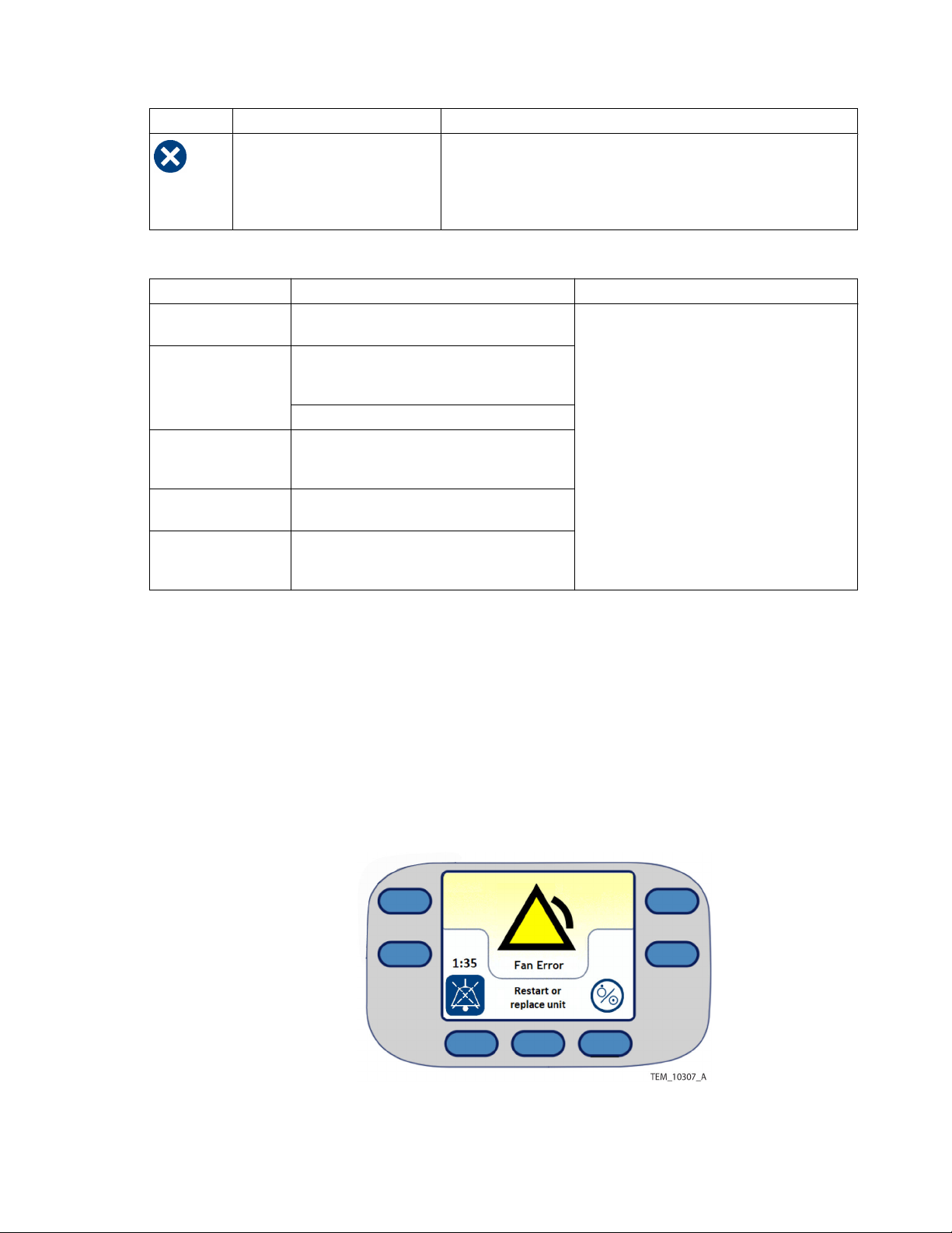
Table 8. Error Indicators
Symbol Tones Type of error
None Software error: An error occurring in the unit software outside of
patient use.
See Clearing Alarms, page 47 for instructions for clearing the error. If
clearing the error is unsuccessful, remove the unit from service until it
can be repaired by qualified personnel.
Table 9. Alarm Conditions
Alarm message Likely cause Resolution
Blanket Overheat The measured air temperature has exceeded
48° C for at least 30 seconds.
Fan Error The fan speed was detected as too fast (>5000
RPM) or too slow (<3000 RPM) to reliably main‐
tain the selected temperature.
The fan experienced a hardware-based failure.
No Heat Delivered The selected temperature has not been
reached within 10 minutes of selecting it in the
main screen.
System Error A software or hardware error was detected
during operation.
Temp Error The measured air temperature is above or
below the selected target temperature, or can‐
not be reliably measured.
Power down the unit, then restart.
If the condition persists, replace the unit.
7.3. Pausing Audible Alarms
When an alarm is active, the unit offers the ability to pause audible alarm tones for 2
minutes.
To pause an audible alarm:
1. Press the audio paused key. The audio paused symbol changes color, and a
countdown timer appears showing the remaining time that the alarm tones are
paused.
Figure 27. Alarm Screen (Alarm Audio Paused)
When the audio paused period ends, the countdown timer disappears, the audio
paused symbol returns to normal, and the alarm tones resume.
46 Operator's Manual English
Page 51
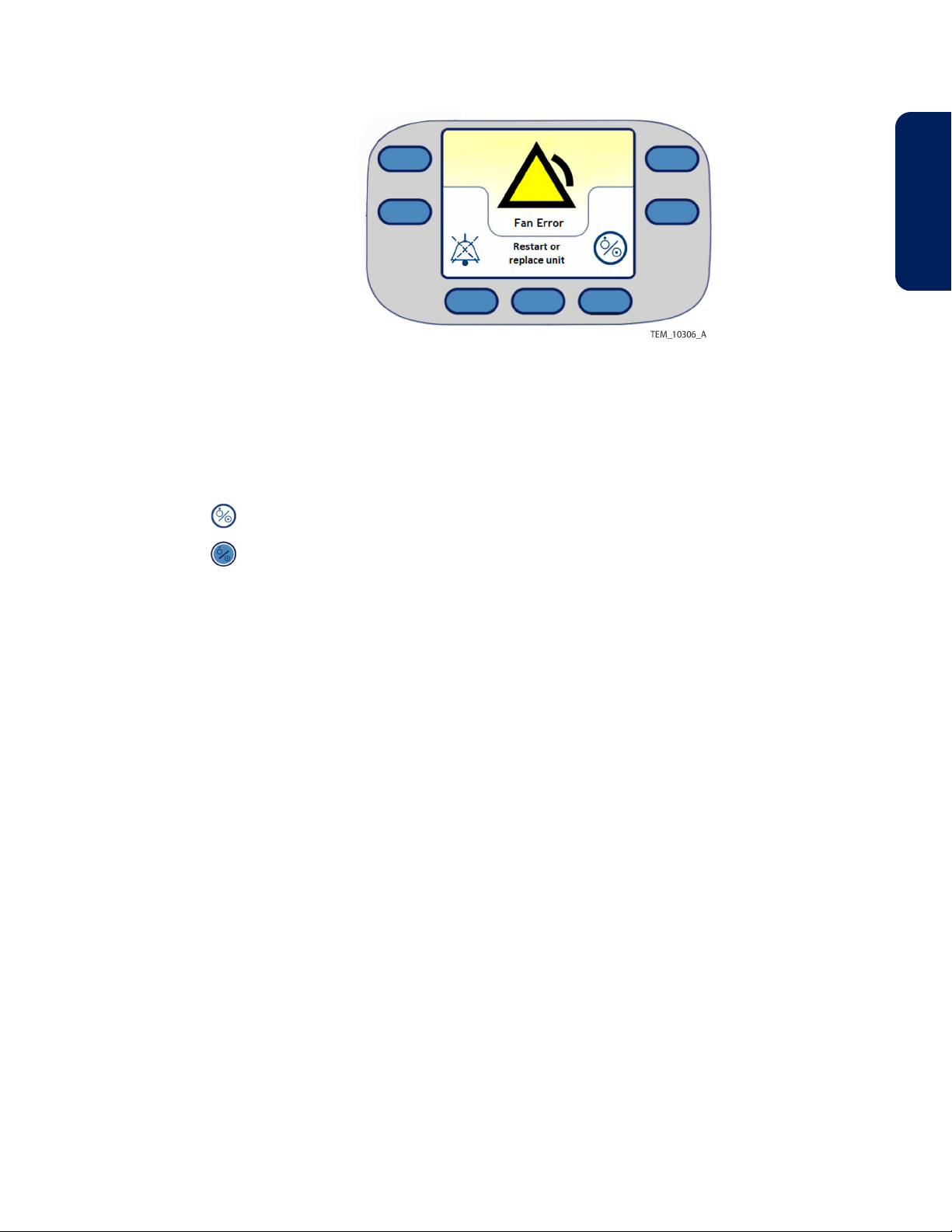
Figure 28. Alarm Screen (Alarm Audio Active)
2. If needed, press the audio paused key again to pause the audible alarm for an
additional 2 minutes.
7.4. Clearing Alarms
To clear a low-priority alarm:
7
1.
2.
If the alarm does not clear, remove the warming unit from operation until it can be repaired
by qualified personnel.
Note: If an alarm condition resolves on its own without operator intervention, visible and
audible alarm indicators will cease and the main screen will appear, without requiring the
unit to be powered down.
Power off the warming unit by pressing the key indicated on the alarm screen.
Press the On/Standby key to power on the warming unit.
Operator's Manual English 47
Page 52

48 Operator's Manual English
Page 53

8. Product Specifications
8.1. Overview
This chapter provides physical and operational specifications for the Covidien
WarmTouch™ convective warming unit.
8.2. Physical Characteristics
Table 10. Warming Unit
Weight with power cord 5.2 kg (11.5 pounds)
Dimensions - hose fully collapsed, nozzle in storage position on unit 60 cm x 43 cm x 30 cm
Power cord length 4.3 m (14 feet)
Table 11. Transport Cart (Optional)
Weight 3.1 kg (6.8 pounds)
Height 67.1 cm (26.4 inches)
Width 32.3 cm (12.7 inches)
Depth 38.6 cm (15.2 inches)
(24 inches x 17 inches x 12 inches)
8
8.3. Electrical Requirements
Table 12. Electrical Requirements
Power requirements 100 to 240 V AC
Max. current at 100 V = 8 A
Max. current at 240 V = 5 A
Input frequency 50/60 Hz ±1 Hz
Fuse (×2) Littlefuse (mfr.) 0218010; 250 V, 10 A
8.4. Environmental Specifications
Table 13. Operating Specifications
Temperature 18°C to 28°C (64.4°F to 82.4°F)
Relative humidity 15% to 85% (non-condensing)
Table 14. Shipping and Storage Specifications
Temperature -40ºC to 70ºC (-40ºF to 158ºF)
Relative humidity 10% to 95% (non-condensing)
Atmospheric pressure 12 kPa to 106 kPa (90 mmHg to 795 mmHg)
Note: Before operating the warming unit after it has been shipped or stored, allow the unit
to acclimate to the operating environment for at least 60 minutes.
Operator's Manual English 49
Page 54

8.5. Performance Specifications
Table 15. Performance Specifications
Maximum contact surface temperature 44.1°C (111.4°F)
Average time for contact surface temperature to rise from 23°C ±2°C
to 37°C
Average time for temperature of air exiting the hose to rise from
23°C ±2°C to 37°C
Accuracy of displayed temperature ±1.0°C (air entering hose)
Automatic temperature stepdown (Boost to High temperature) After 45 minutes of continuous use, blower will
Thermal protection threshold Thermostat (internal):
Average alarm level 56 dB @ 1 meter
6 minutes
<1 minute
step down from Boost to High setting
49°C to 55°C (120°F to 131°F)
8.6. Product Compliance
Table 16. Product Compliance
Equipment classification IEC 60601-1:2005 + A1:2012, EN 60601-1:2006 + A12:2014
ANSI/AAMI ES60601-1:2005(R)2012
EN 60601-1-8:2007 + A11:2017
CAN/CSA C22.2 No 60601-1:14
IEC 80601-2-35:2009 + A1:2016
EN 80601-2-35:2009 + A1:2016
Protection type Class I
Degree of protection Type BF - Applied part
Mode of operation Continuous
Electromagnetic compatibility IEC 60601-1-2:2014, EN 60601-1-2:2015, Class A Emissions
IEC/EN 80601-2-35:2009 + A1:2016
Protection against ingress of fluids Ordinary
8.7. Electromagnetic Compatibility (EMC)
8.7.1. Manufacturer’s Declaration
The warming system is suitable for prescription use only in the specified electromagnetic
environments. Use the warming system in accordance with the electromagnetic
environments described in the following sections.
50 Operator's Manual English
Page 55

8.7.2. Electromagnetic Emissions
Table 17. Electromagnetic Emissions Guidelines
Guidance and manufacturer’s declaration—electromagnetic emissions (IEC 60601-1-2:2014, EN 60601-1-2:2015, Table 1)
The warming system is intended for use in the electromagnetic environment specified below. The customer or the user
of the warming system should assure that it is used in such an environment.
Emissions test Compliance Electromagnetic environment guidance
RF emission
CISPR 11
Harmonic emission
IEC/EN 61000-3-2
Voltage fluctua‐
tion/flicker emissions
IEC/EN 61000-3-3
Caution: The warming system is not intended for use in residential environments and may
not provide adequate protection to radio communication services in such environments.
Group 1, Class A This is a class A product per IEC CISPR 11 and is not
intended to be used in a residential environment. If
used in a domestic environment, this equipment may
not offer adequate protection to radio-frequency
communication services. The user may be required to
take mitigation measures, such as relocating or re-ori‐
enting the equipment.
Class A The warming system is suitable for use in all establish‐
ments other than domestic and those directly con‐
Complies
nected to the public low-voltage power network that
supplies buildings used for domestic purposes.
8
8.7.3. Electromagnetic Immunity
Table 18. Electromagnetic Immunity Guidelines
Guidance and manufacturer’s declaration—electromagnetic immunity (IEC 60601-1-2:2014, EN 60601-1-2:2015, Table 2)
The warming system is intended for use in the electromagnetic environment specified below. The customer or the user
of the warming system should assure that it is used in such an environment.
Immunity test IEC/EN 60601-1-2 test
Electrostatic discharge
(ESD)
IEC/EN 61000-4-2
Electric fast transi‐
ent/burst
IEC/EN 61000-4-4
Surge
IEC/EN 61000-4-5
Voltage dips, short inter‐
ruptions and voltage var‐
iations on power supply
IEC/EN 61000-4-11
±6 kV contact
±8 kV air
±2 kV for power supply
lines
±1 kV input/output
lines
±1 kV line(s) to line(s)
±2 kV line(s) to earth
<5% UT (>95% dip in
UT) for 0.5 cycle
40% UT (60% dip in UT)
for 5 cycles
70% UT (30% dip in UT)
for 25 cycles
<5% UT (>95% dip in
UT) for 5 seconds
level
Compliance level Electromagnetic environment guidance
±6 kV contact
±8 kV air
±2 kV for power supply
lines
±1 kV input/output
lines
±1 kV line(s) to line(s)
±2 kV line(s) to earth
<5% UT (>95% dip in
UT) for 0.5 cycle
40% UT (60% dip in UT)
for 5 cycles
70% UT (30% dip in UT)
for 25 cycles
<5% UT (>95% dip in
UT) for 5 seconds
Floors should be wood, concrete, or
ceramic tile. If floors are covered with syn‐
thetic material, the relative humidity
should be at least 30%.
Mains power quality should be that of a
typical commercial or hospital environ‐
ment.
Mains power quality should be that of a
typical commercial or hospital environ‐
ment.
Mains power quality should be that of a
typical commercial or hospital environ‐
ment.
If the user of the warming system requires
continued operation during power mains
interruption, it is recommended that the
warming system be powered from an
uninterruptible power supply or battery.
Operator's Manual English 51
Page 56

Table 18. Electromagnetic Immunity Guidelines (continued)
Guidance and manufacturer’s declaration—electromagnetic immunity (IEC 60601-1-2:2014, EN 60601-1-2:2015, Table 2)
The warming system is intended for use in the electromagnetic environment specified below. The customer or the user
of the warming system should assure that it is used in such an environment.
Immunity test IEC/EN 60601-1-2 test
level
Power frequency (50/60
Hz) magnetic field
IEC/EN 61000-4-8
Note: UT is the AC main’s voltage prior to application of the test level.
3 A/m 3 A/m Power frequency magnetic fields should
Compliance level Electromagnetic environment guidance
be at levels characteristic of a typical loca‐
tion in a typical commercial or hospital
environment.
52 Operator's Manual English
Page 57

Table 19. Recommended Separation Distance Calculations
Guidance and manufacturer’s declaration—electromagnetic immunity (IEC 60601-1-2:2014, EN 60601-1-2:2015, Table 4)
The warming system is intended for use in the electromagnetic environment specified below. The customer or the user
of the warming system should assure that it is used in such an environment.
Immunity test IEC/EN 60601-1-2 test
level
Conducted RF
IEC/EN 61000-4-6
Radiated RF
IEC/EN 61000-4-3
3 Vrms
150 kHz
80 MHz
3 V/m
80 MHz
800 MHz
3 V/m
800 MHz
2.5 GHz
Compliance level Electromagnetic environment guidance
3 Vrms
150 kHz
80 MHz
3 V/m
80 MHz
800 MHz
3 V/m
800 MHz
2.5 GHz
Portable and mobile RF communications equip‐
ment should be used no closer to any part of the
warming system, including cables, than the rec‐
ommended separation distance calculated from
the equation applicable to the frequency of the
transmitter.
Recommended Separation Distance
d = 1.2 √P
150 kHz to 80 MHz
d = 1.2 √P
80 MHz to 800 MHz
d = 2.3 √P
800 MHz to 2.5 GHz
where P is the maximum output power rating of
the transmitter in watts (W) according to the
transmitter manufacturer and d is the recom‐
mended separation distance in meters (m).
Field strengths from fixed RF transmitters, as
determined by an electromagnetic site survey a ,
should be less than the compliance level in each
frequency range b.
Interference may occur in the vicinity of equip‐
ment marked with the following symbol:
8
NOTE 1: At 80 MHz and 800 MHz, the higher frequency range applies.
NOTE 2: These guidelines may not apply in all situations. Electromagnetic propagation is affected by absorption and
reflection from structures, objects, and people.
a
Field strengths from fixed transmitters, such as base stations for radio (cellular/cordless) telephones and land mobile radios, amateur radio, AM and FM
radio broadcast and TV broadcast cannot be predicted theoretically with accuracy. To assess the electromagnetic environment due to fixed RF
transmitters, an electromagnetic site survey should be considered. If the measured field strength in the location in which the warming system is used
exceeds the applicable RF compliance level above, the warming system should be observed to verify normal operation. If abnormal performance is
observed, additional measures may be necessary, such as re-orienting or relocating the warming system.
b
Over the frequency range 150 kHz to 80 MHz, field strengths should be less than 3 V/m.
Operator's Manual English 53
Page 58

Table 20. Recommended Separation Distances
Recommended separation distances between portable and mobile RF communications equipment and the warming
system (IEC 60601-1-2:2014, EN 60601-1-2:2015, Table 7)
The warming system is intended for use in an electromagnetic environment in which radiated RF disturbances are con‐
trolled. The customer or the user of the warming system can help prevent electromagnetic interference by maintaining
a minimum distance between portable and mobile RF communications equipment (transmitters) and the warming sys‐
tem as recommended below, according to the maximum output power of the communications equipment.
Rated maximum output
power (P) of transmitter in
watts
0.01 0.12 0.12 0.23
0.10 0.38 0.38 0.73
1.00 1.20 1.20 2.30
10.00 3.80 3.80 7.30
100.00 12.00 12.00 23.00
For transmitters rated at a maximum output power not listed above, estimate the separation distance (d) using the
equation in the corresponding column, where P is the maximum output [power rating of the transmitter in watts (W)]
according to the transmitter manufacturer.
Note 1: At 80 MHz and 800 MHz, the separation distance for the higher frequency range applies.
Note 2: These guidelines may not apply in all situations. Electromagnetic propagation is affected by absorption and
reflection from structures, objects and people.
150 kHz to 80 MHz
d = 1.2 √P
Separation distance in meters
80 MHz to 800 MHz
d = 1.2 √P
800 MHz to 2.7 GHz
d = 2.3 √P
8.8. Ground Integrity Test
Without power cord: ≤100 mΩ
With power cord: ≤200 mΩ
8.9. Earth Leakage Current Test
Table 21. Earth Leakage Current Test
AC polarity Line cord Neutral cord Leakage current
Normal Closed Closed 300 μA
Reversed Closed Closed 300 μA
Normal Open Closed 1000 μA
Normal Closed Open 1000 μA
8.10. Enclosure Leakage Current Test
Table 22. Enclosure Leakage Current Test
AC line cord Neutral line cord Power line ground cable AAMI / ANSI Standard ES1
Normal Closed Closed 100 μA
Normal Closed Open 500 μA
Normal Open Closed 500 μA
Reversed Closed Closed 100 μA
54 Operator's Manual English
Page 59

Table 22. Enclosure Leakage Current Test (continued)
AC line cord Neutral line cord Power line ground cable AAMI / ANSI Standard ES1
Reversed Open Closed 500 μA
Reversed Closed Open 500 μA
8
Operator's Manual English 55
Page 60

56 Operator's Manual English
Page 61

9. Error Codes
9.1. Overview
This chapter defines the error codes that may be generated during operation of the
WarmTouch™ convective warming unit.
Warming unit alarms and system errors (hardware-related or software-related) generate
specific error codes. View the most recent error codes on the System Information screen, as
shown in System Information, page 42. Service personnel can also access the unit's error
and event log if needed.
Suggested resolutions are provided for each error. If an error situation cannot be resolved,
or if you see an error code that is not listed, contact Covidien Technical Services.
See Obtaining Technical Assistance, page 7.
9.2. Error Codes and Suggested Resolutions
9.2.1. Error Categories
Warming unit errors are divided into three categories:
•
A/D—Errors associated with or reported by the A/D microprocessor.
•
POST—Errors occurring during power-on self-test.
•
UI—Errors associated with or reported by the UI microprocessor.
9.2.2. Error Code and Resolution List
Table 23. Error Codes and Resolutions
003
Category: A/D
Description: Checksum error on code in flash. A/D flash is defective.
Resolution: Turn power off to the warming unit, then turn power back on.
If the error persists, remove the unit from use for servicing by qualified personnel.
004
Category: A/D
Description: One of the following conditions occurred:
•
Temperature was more than ±1°C from the setpoint for at least 30 consecutive seconds after the set‐
point was reached.
•
Temperature did not reach the specified setpoint within 10 minutes.
Resolution: Turn power off to the warming unit, then turn power back on.
If the error persists, remove the unit from use for servicing by qualified personnel.
005
Category: A/D
Description: Temperature >48°C for at least 30 consecutive seconds.
9
Operator's Manual English 57
Page 62

Table 23. Error Codes and Resolutions (continued)
Resolution: Turn power off to the warming unit, then turn power back on.
If the error persists, remove the unit from use for servicing by qualified personnel.
006
Category: A/D
Description: Thermal cut-out switch has opened.
Resolution: Turn power off to the warming unit, then turn power back on.
If the error persists, remove the unit from use for servicing by qualified personnel.
011
Category: A/D
Description: Thermistor temperature too low to measure.
Resolution: Turn power off to the warming unit, then turn power back on.
If the error persists, remove the unit from use for servicing by qualified personnel.
012
Category: A/D
Description: Thermistor temperature too high to measure.
Resolution: Turn power off to the warming unit, then turn power back on.
If the error persists, remove the unit from use for servicing by qualified personnel.
013
Category: A/D
Description: Fan motor drew too much current.
Resolution: Turn power off to the warming unit, then turn power back on.
If the error persists, remove the unit from use for servicing by qualified personnel.
014
Category: A/D
Description: Fan speed <3000 rpm.
Resolution: Turn power off to the warming unit, then turn power back on.
If the error persists, remove the unit from use for servicing by qualified personnel.
015
Category: A/D
Description: Fan speed > 5000 rpm.
Resolution: Turn power off to the warming unit, then turn power back on.
If the error persists, remove the unit from use for servicing by qualified personnel.
016
Category: A/D
Description: Fan speed too low for current fan voltage.
Resolution: Turn power off to the warming unit, then turn power back on.
If the error persists, remove the unit from use for servicing by qualified personnel.
017
Category: A/D
Description: Fan speed too high for current fan voltage
Resolution: Turn power off to the warming unit, then turn power back on.
If the error persists, remove the unit from use for servicing by qualified personnel.
028
58 Operator's Manual English
Page 63

Table 23. Error Codes and Resolutions (continued)
Category: A/D
Description: Flash erase error during software upgrade.
Resolution: Turn power off to the warming unit, then turn power back on.
If the error persists, remove the unit from use for servicing by qualified personnel.
029
Category: A/D
Description: Flash write error during software upgrade.
Resolution: Turn power off to the warming unit, then turn power back on.
If the error persists, remove the unit from use for servicing by qualified personnel.
030
Category: A/D
Description: Flash verify error during software upgrade.
Resolution: Turn power off to the warming unit, then turn power back on.
If the error persists, remove the unit from use for servicing by qualified personnel.
031
Category: A/D
Description: Invalid flash state (software error) during software upgrade.
Resolution: Turn power off to the warming unit, then turn power back on.
If the error persists, remove the unit from use for servicing by qualified personnel.
032
Category: A/D
Description: Checksum error on downloaded software during software upgrade.
Resolution: Turn power off to the warming unit, then turn power back on.
If the error persists, remove the unit from use for servicing by qualified personnel.
033
Category: A/D
Description: Timeout on A/D SW update data message during software upgrade.
Resolution: Turn power off to the warming unit, then turn power back on.
If the error persists, remove the unit from use for servicing by qualified personnel.
038
Category: A/D
Description: Too many consecutive CRC errors in SPI commands.
Resolution: Turn power off to the warming unit, then turn power back on.
If the error persists, remove the unit from use for servicing by qualified personnel.
045
Category: A/D
Description: Thermistor open circuit.
Resolution: Turn power off to the warming unit, then turn power back on.
If the error persists, remove the unit from use for servicing by qualified personnel.
046
Category: A/D
Description: Thermistor shorted.
9
Operator's Manual English 59
Page 64

Table 23. Error Codes and Resolutions (continued)
Resolution: Turn power off to the warming unit, then turn power back on.
If the error persists, remove the unit from use for servicing by qualified personnel.
048
Category: A/D
Description: Fan voltage >48.1 V (or >10 V when turned off).
Resolution: Turn power off to the warming unit, then turn power back on.
If the error persists, remove the unit from use for servicing by qualified personnel.
049
Category: A/D
Description: Fan voltage <10 V.
Resolution: Turn power off to the warming unit, then turn power back on.
If the error persists, remove the unit from use for servicing by qualified personnel.
051
Category: A/D
Description: Thermistor values not changing.
Resolution: Turn power off to the warming unit, then turn power back on.
If the error persists, remove the unit from use for servicing by qualified personnel.
053
Category: A/D
Description: No edges detected on AC_STATUS signal.
Resolution: N/A (indicates that the power cord was disconnected while the unit was still powered on).
131
Category: POST
Description: RAM check error during POST.
Resolution: Turn power off to the warming unit, then turn power back on.
If the error persists, remove the unit from use for servicing by qualified personnel.
132
Category: POST
Description: Clock frequency error during POST.
Resolution: Turn power off to the warming unit, then turn power back on.
If the error persists, remove the unit from use for servicing by qualified personnel.
133
Category: POST
Description: Keypad error during unit power-on self test (POST). Typically, this occurs when the user presses a key while
POST is running.
Resolution: If this error occurs without a key being pressed during POST, turn power off to the warming unit, then turn
power back on.
If the error persists, remove the unit from use for servicing by qualified personnel.
138
Category: POST
Description: Flash write/read test failed during POST.
Resolution: Turn power off to the warming unit, then turn power back on.
If the error persists, remove the unit from use for servicing by qualified personnel.
60 Operator's Manual English
Page 65

Table 23. Error Codes and Resolutions (continued)
140
Category: POST
Description: RTC NVRAM write/read test failed during POST.
Resolution: Turn power off to the warming unit, then turn power back on.
If the error persists, remove the unit from use for servicing by qualified personnel.
144
Category: POST
Description: UI calculated checkword does not match the stored checkword.
Resolution: Turn power off to the warming unit, then turn power back on.
If the error persists, remove the unit from use for servicing by qualified personnel.
145
Category: POST
Description: GPX calculated checkword does not match the stored checkword.
Resolution: Turn power off to the warming unit, then turn power back on.
If the error persists, remove the unit from use for servicing by qualified personnel.
152
Category: UI
Description: External watchdog timed out.
Resolution: Turn power off to the warming unit, then turn power back on.
If the error persists, remove the unit from use for servicing by qualified personnel.
157
Category: UI
Description: Thermostat open.
Resolution: Turn power off to the warming unit, then turn power back on.
If the error persists, remove the unit from use for servicing by qualified personnel.
158
Category: UI
Description: One of the following conditions occurred:
•
Temperature was more than ±1°C from the setpoint for at least 30 consecutive seconds after the set‐
point was reached.
•
Temperature did not reach the specified setpoint within 10 minutes.
Resolution: Turn power off to the warming unit, then turn power back on.
If the error persists, remove the unit from use for servicing by qualified personnel.
159
Category: UI
Description: Temperature >48°C for at least 30 consecutive seconds.
Resolution: Turn power off to the warming unit, then turn power back on.
If the error persists, remove the unit from use for servicing by qualified personnel.
163
Category: UI
Description: Bad CRC on packet received from AD microprocessor.
9
Operator's Manual English 61
Page 66

Table 23. Error Codes and Resolutions (continued)
Resolution: This error may appear due to electromagnetic interference from other devices. Try increasing the distance
between devices, repositioning the cabling, or plugging the devices into separate outlet circuit branches.
See Electromagnetic Compatibility (EMC), page 50 for additional guidance.
Turn power off to the warming unit, then turn power back on.
If the error persists, remove the unit from use for servicing by qualified personnel.
165
Category: UI
Description: No communication from A/D microprocessor.
Resolution: Turn power off to the warming unit, then turn power back on.
If the error persists, remove the unit from use for servicing by qualified personnel.
175
Category: UI
Description: Software upgrade cannot proceed due to checkword check error. Software file may be corrupted.
Resolution: Turn power off to the warming unit, then turn power back on.
If the error persists, remove the unit from use for servicing by qualified personnel.
176
Category: UI
Description: Software upgrade cannot proceed due to header check error. Software file may be corrupted or invalid.
Resolution: Turn power off to the warming unit, then turn power back on.
If the error persists, remove the unit from use for servicing by qualified personnel.
177
Category: UI
Description: The UI microprocessor received a message from the A/D microprocessor indicating that the heater and fan
were shut down. Cause is typically provided in subsequent error messages.
Resolution: N/A (refer to subsequent error messages)
178
Category: UI
Description: The UI microprocessor received a message from the A/D microprocessor indicating that the fan was shut
down. Cause is typically provided in subsequent error messages.
Resolution: N/A (refer to subsequent error messages)
179
Category: UI
Description: The UI microprocessor received a message from the A/D microprocessor indicating that the heater was
shut down. Cause is typically provided in subsequent error messages.
Resolution: N/A (refer to subsequent error messages)
181
Category: UI
Description: Corrupt data in the RTC section of the RTC chip.
Resolution: Turn power off to the warming unit, then turn power back on.
If the error persists, remove the unit from use for servicing by qualified personnel.
182
Category: UI
Description: Unable to communicate with the RTC chip.
62 Operator's Manual English
Page 67
Table 23. Error Codes and Resolutions (continued)
Resolution: Turn power off to the warming unit, then turn power back on.
If the error persists, remove the unit from use for servicing by qualified personnel.
184
Category: UI
Description: RTC NVRAM contained an illegal setpoint temperature.
Resolution: Turn power off to the warming unit, then turn power back on.
If the error persists, remove the unit from use for servicing by qualified personnel.
186
Category: UI
Description: Error communicating with A/D microprocessor across SPI bus.
Resolution: Turn power off to the warming unit, then turn power back on.
If the error persists, remove the unit from use for servicing by qualified personnel.
202
Category: UI
Description: UI microprocessor is receiving too many interrupts from the A/D microprocessor.
Resolution: This error may appear due to electromagnetic interference from other devices. Try increasing the distance
between devices, repositioning the cabling, or plugging the devices into separate outlet circuit branches.
See Electromagnetic Compatibility (EMC), page 50 for additional guidance.
Turn power off to the warming unit, then turn power back on.
If the error persists, remove the unit from use for servicing by qualified personnel.
204
Category: UI
Description: Spurious interrupt from A/D microprocessor.
Resolution: This error may appear due to electromagnetic interference from other devices. Try increasing the distance
between devices, repositioning the cabling, or plugging the devices into separate outlet circuit branches.
See Electromagnetic Compatibility (EMC), page 50 for additional guidance.
Turn power off to the warming unit, then turn power back on.
If the error persists, remove the unit from use for servicing by qualified personnel.
205
Category: UI
Description: Bad checksum or other failure during file download for software upgrade.
Resolution: Turn power off to the warming unit, then turn power back on.
If the error persists, remove the unit from use for servicing by qualified personnel.
207
Category: UI
Description: The length of the UI code image downloaded to external flash is too small.
Resolution: Turn power off to the warming unit, then turn power back on.
If the error persists, remove the unit from use for servicing by qualified personnel.
211
Category: UI
Description: The UI and A/D microprocessors disagree as to the temperature setpoint.
9
Operator's Manual English 63
Page 68

Table 23. Error Codes and Resolutions (continued)
Resolution: This error may appear due to electromagnetic interference from other devices. Try increasing the distance
between devices, repositioning the cabling, or plugging the devices into separate outlet circuit branches.
See Electromagnetic Compatibility (EMC), page 50 for additional guidance.
Turn power off to the warming unit, then turn power back on.
If the error persists, remove the unit from use for servicing by qualified personnel.
213
Category: UI
Description: Read error from RTC.
Resolution: This error may appear due to electromagnetic interference from other devices. Try increasing the distance
between devices, repositioning the cabling, or plugging the devices into separate outlet circuit branches.
See Electromagnetic Compatibility (EMC), page 50 for additional guidance.
Turn power off to the warming unit, then turn power back on.
If the error persists, remove the unit from use for servicing by qualified personnel.
214
Category: UI
Description: Write error to RTC.
Resolution: This error may appear due to electromagnetic interference from other devices. Try increasing the distance
between devices, repositioning the cabling, or plugging the devices into separate outlet circuit branches.
See Electromagnetic Compatibility (EMC), page 50 for additional guidance.
Turn power off to the warming unit, then turn power back on.
If the error persists, remove the unit from use for servicing by qualified personnel.
215
Category: UI
Description: Unspecified RTC error.
Resolution: This error may appear due to electromagnetic interference from other devices. Try increasing the distance
between devices, repositioning the cabling, or plugging the devices into separate outlet circuit branches.
See Electromagnetic Compatibility (EMC), page 50 for additional guidance.
Turn power off to the warming unit, then turn power back on.
If the error persists, remove the unit from use for servicing by qualified personnel.
64 Operator's Manual English
Page 69

i
Page 70

Covidien llc,
15 Hampshire Street, Mansfield, MA 02048 USA
Covidien Ireland Limited
IDA Business and Technology Park, Tullamore, Ireland.
www.covidien.com
1 800 635 5267 [T]
© 2020 Covidien. All rights reserved.
PT00115497 Rev. A
2020-05-14
 Loading...