

Page 1
ATTAIN PERFORMA™ S MRI SURESCAN™ 4598
Steroid-eluting, quadripolar electrode, transvenous, over-the-wire, cardiac vein pacing lead
Technical Manual
Caution: Federal law (USA) restricts this device to sale by or on the order of a physician.
Page 2

The following list includes trademarks or registered trademarks of Medtronic in the United States and possibly in other countries. All other trademarks
are the property of their respective owners.
AccuRead, Attain, Attain Hybrid, Medtronic, Performa, SureScan
Page 3

Contents
1 Description 3
2 Drug component description 4
3 Indications 4
4 Contraindications 4
5 Warnings and precautions 4
6 Potential adverse events 6
7 Drug information 7
8 Clinical study 8
9 Implant procedure 8
10 Specifications 15
11 Medtronic warranty 16
12 Service 16
1 Description
The Medtronic Attain Performa S MRI SureScan 4598
steroid-eluting, quadripolar electrode, transvenous, over-the-wire
LV lead is designed for pacing via a cardiac vein. The lead has
been tested for use in the Magnetic Resonance Imaging (MRI)
environment. All lead lengths for this lead model are MR
Conditional. This lead contains 4 electrodes designed to function
as cathodes or anodes, depending on how the device LV pacing
polarity is programmed:
●
electrode LV1, the distal electrode, positioned near the distal
tip of the lead
●
electrode LV2, positioned 21 mm proximal to electrode LV1
●
electrode LV3, positioned 1.3 mm proximal to electrode LV2
●
electrode LV4, the proximal electrode, positioned 21 mm
proximal to electrode LV3
See Section 9.10, “Taking electrical measurements”, page 11
for information about LV pacing polarity selections.
The Medtronic IS4-LLLL1 four-pole inline connector on the lead
facilitates device connection during implant. The tip of the
connector pin has a white band indicator that can be used for
visual confirmation of proper lead connection to the device.
The connector contacts align with the lead electrodes LV1 to LV1,
LV2 to LV2, and so on:
●
connector contact LV1, the connector pin, positioned at the
proximal tip of the lead (aligns to electrode LV1)
●
connector contact LV2, positioned distal to connector pin LV1
(aligns to electrode LV2)
●
connector contact LV3, positioned distal to connector contact
LV2 (aligns to electrode LV3)
●
connector contact LV4, positioned distal to connector contact
LV3 (aligns to electrode LV4)
See Section 10.2, “Specifications drawing (nominal)”, page 16
for an illustration of the lead electrodes and connector contacts.
The distal tip of the lead allows a guide wire to pass through to aid
in cardiac vein selection. The tip contains a silicone rubber
membrane, which seals the lead inner lumen to reduce blood
ingress.
Each electrode contains a Monolithic controlled release device
(MCRD) for elution of steroid to reduce inflammatory response
within the cardiac vein. The MCRDs contain a combined-total
target dosage of 288 µg of dexamethasone acetate steroid. The
target dose of the steroid is 72 µg at each MCRD. Upon exposure
to body fluids, the steroid elutes from the MCRDs. The steroid
suppresses the inflammatory response that is believed to cause
threshold rise typically associated with implanted pacing
electrodes.
The electrodes are positioned relative to the 3 distal curves of the
lead to facilitate contact with the cardiac veins.
The outer insulation of the lead is polyurethane and the inner
insulation is SI-polyimide (SI-PI)2. The SI-PI is applied as a
coating to the conductor wire before coiling.
The Attain Performa S MRI SureScan 4598 LV lead can be
positioned with the aid of a guide wire, a stylet, an inner catheter,
or an inner catheter plus a guide wire or a stylet.
To implant the lead in a selected cardiac vein, a compatible
delivery system is required. A compatible delivery system
includes a guide catheter and either a hemostasis valve or an
introducer valve that can be removed or that allows passage over
the lead connector. Contact a Medtronic representative for further
information regarding compatible delivery systems.
1.1 Medtronic SureScan system
The Model 4598 lead is part of the Medtronic SureScan system.
The SureScan system includes a Medtronic SureScan device
connected to Medtronic SureScan leads. Labeling for SureScan
system components displays the SureScan logo and the MR
Conditional symbol. To verify that components are part of a
SureScan system, visit http://www.mrisurescan.com.
SureScan logo
MR Conditional symbol. The Medtronic SureScan system is MR Conditional and is designed to allow implanted patients to undergo an MRI scan under the specified MRI conditions for use.
1
IS4-LLLL refers to an International Connector Standard (ISO 27186:2010) whereby pulse generators and leads so designated are assured of a basic mechanical fit.
LLLL defines the lead connector contacts as low voltage (L).
2
Technology developed by NASA.
3
Page 4
The MRI SureScan feature permits a mode of operation that
allows a patient with a SureScan device to be safely scanned by
an MRI machine while the device continues to provide appropriate
pacing. When programmed to On, MRI SureScan operation
disables arrhythmia detection, magnet mode, and all
user-defined diagnostics. Before performing an MRI scan,
refer to the SureScan MRI technical manual for important
information about procedures and MRI-specific warnings
and precautions.
1.2 Contents of package
Leads and accessories are supplied sterile. Each package
contains the following items:
●
1 lead with anchoring sleeve
●
1 guide wire insertion tool
●
1 guide wire clip
●
1 guide wire steering handle
●
4 stylets
●
2 AccuRead 2.0 analyzer cable interface tools
●
product documentation
1.3 Accessory descriptions
Dispose of all single-use accessories according to local
environmental requirements.
AccuRead 2.0 tool – The AccuRead 2.0 analyzer cable interface
tool guides the connection of analyzer cable terminals to the lead
connector contacts. This connection facilitates accurate electrical
measurements during implant and prevents possible connector
damage.
Anchoring sleeve – An anchoring sleeve secures the lead to
prevent it from moving and protects the lead insulation and
conductors from damage caused by tight sutures.
Guide wire clip – A guide wire clip secures the excess guide wire
and helps to protect and maintain the sterility of the guide wire.
Guide wire insertion tool – A guide wire insertion tool provides
additional control when inserting a guide wire into the lead
connector pin or the lead tip.
Guide wire steering handle – A guide wire steering handle is
used only with guide wires 0.46 mm (0.018 in) or less in diameter.
The steering handle provides additional guide wire steering and
rotation control.
Stylet – A stylet provides additional stiffness and controlled
flexibility for maneuvering the lead into position. Each stylet knob
is labeled with the stylet diameter and corresponding lead length.
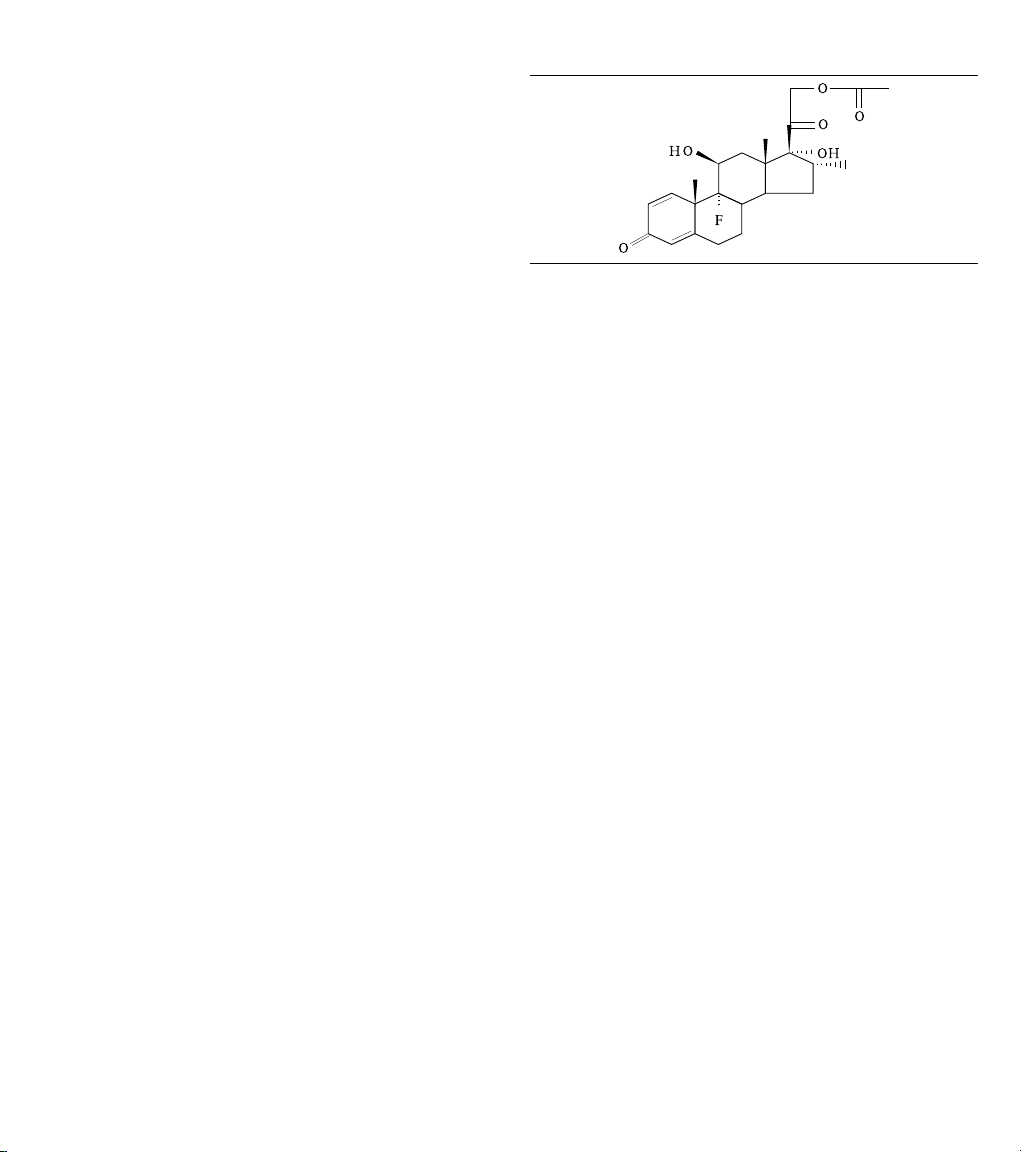
2 Drug component description
The active ingredient in the Attain Performa S MRI SureScan 4598
LV lead is dexamethasone acetate [21-(acetyloxy)-9-fluoro-11β,
17-trihydroxy-16α-methylpregna-1,4-diene-3,20-dione]. The
structural formula for this steroid is as follows:
Dexamethasone acetate (DXAC) - C24H31FO
6
Figure 1.
The target dosage of dexamethasone acetate is 288 µg per lead.
Cautions:
●
Drug interactions of dexamethasone acetate with this lead
have not been studied.
●
Before implanting this lead, consider total patient exposure to
dexamethasone acetate.
3 Indications
The Attain Performa S MRI SureScan 4598 steroid-eluting,
quadripolar electrode, IS4 transvenous lead is indicated for
chronic pacing in the left ventricle via the cardiac vein, when used
with a compatible Medtronic Cardiac Resynchronization Therapy
(CRT) system. Extended bipolar pacing is available using this lead
in combination with a compatible CRT-D system and RV
defibrillation lead.
4 Contraindications
Before performing an MRI scan, refer to the SureScan MRI
technical manual for MRI-specific contraindications.
The Model 4598 lead is contraindicated as follows:
Coronary vasculature – This lead is contraindicated for patients
with coronary venous vasculature that is inadequate for lead
placement, as indicated by venogram.
Steroid use – The lead is contraindicated in patients for whom a
single dose of 288 µg of dexamethasone acetate may
be contraindicated.
5 Warnings and precautions
A complete SureScan system is required for use in the MRI
environment. Before performing an MRI scan, refer to the
SureScan MRI technical manual for MRI-specific warnings
and precautions.
Note: Medical procedure warnings and precautions that pertain
to the Medtronic implanted system are provided in the manual that
is packaged with the device or on the Medtronic Manual Library
website (www.medtronic.com/manuals).
4
Page 5

Inspecting the sterile package – Inspect the sterile package
with care before opening it.
●
If the seal or package is damaged, contact a Medtronic
representative.
●
Store at 25 °C (77 °F). Excursions from this storage
temperature are permitted in the range of 15 to 30 °C (59 to
86 °F). (See USP Controlled Room Temperature.) According
to USP excursion conditions, transient spikes up to 40 °C
(104 °F) are permitted as long as they do not exceed 24 hours.
●
Do not use the product after its expiration date.
Sterilization – Medtronic has sterilized the package contents
with ethylene oxide before shipment. This lead is for single use
only and is not intended to be resterilized.
Single use – The lead and accessories are for single use only.
Necessary hospital equipment – Keep external defibrillation
equipment nearby for immediate use during acute lead system
testing, the implant procedure, or whenever arrhythmias are
possible or intentionally induced during post-implant testing.
External defibrillation and cardioversion – External
defibrillation and cardioversion are therapies that deliver an
electrical shock to the heart to convert an abnormal heart rhythm
to a normal rhythm.
Medtronic cardiac devices are designed to withstand exposure to
external defibrillation and cardioversion. While damage to an
implanted system from an external shock is rare, the probability
increases with increased energy levels. These procedures may
also temporarily or permanently elevate pacing thresholds or
temporarily or permanently damage the myocardium. If external
defibrillation or cardioversion are required, consider the following
precautions:
●
Use the lowest clinically appropriate energy.
●
Position the patches or paddles a minimum of 15 cm (6 in)
away from the device.
●
Position the patches or paddles perpendicular to the device
and lead system.
●
If an external defibrillation or cardioversion is delivered within
15 cm (6 in) of the device, use a Medtronic programmer to
evaluate the device and lead system.
Line-powered and battery-powered equipment – An
implanted lead forms a direct current path to the myocardium.
During lead implant and testing, use only battery-powered
equipment or line-powered equipment specifically designed for
this purpose to protect against fibrillation that may be caused by
alternating currents. Line-powered equipment used in the vicinity
of the patient must be properly grounded. Lead connector pins
must be insulated from any leakage currents that may arise from
line-powered equipment.
Concurrent devices – Output pulses, especially from unipolar
devices, may adversely affect device sensing capabilities. If a
patient requires a separate stimulation device, either permanent
or temporary, allow enough space between the leads of the
separate systems to avoid interference in the sensing capabilities
of the devices. Previously implanted pulse generators and
implantable cardioverter defibrillators should generally be
explanted.
Steroid use – It has not been determined whether the warnings,
precautions, or complications usually associated with injectable
dexamethasone acetate apply to the use of this highly localized,
controlled-release device. For a list of potential adverse effects,
refer to the Physicians’ Desk Reference.
Handling steroid monolithic controlled release devices
(MCRDs) – Avoid reducing the amount of steroid available before
implanting the lead. Reducing the available amount of steroid may
adversely affect low-threshold performance.
●
Do not allow the electrode surfaces to come in contact with
surface contaminants.
●
Do not wipe or immerse the electrodes in fluid, except blood,
at the time of implant.
Bipolar pacing – If the surface area of the selected anode
electrode is equal to or less than the surface area of the selected
cathode, higher pacing thresholds or anodal stimulation may
result. This lead uses 4 equal-sized electrodes; therefore, bipolar
pacing configurations may result in higher pacing thresholds or
anodal stimulation.
If therapy cannot be delivered via the LV1 electrode, the LV2, LV3,
and LV4 electrodes are available for use with specific Medtronic
devices. Refer to the appropriate Medtronic Cardiac
Resynchronization Therapy (CRT-D) system manual for use of
available LV lead pacing polarity options.
Handling the stylet – Handle the stylet with care at all times.
●
To minimize the likelihood of trauma to the vein and to
maintain lead flexibility while advancing the lead through the
vein, keep the stylet withdrawn 1 to 2 cm or select a more
flexible stylet.
●
Do not use excessive force or surgical instruments when
inserting a stylet.
●
Avoid overbending, kinking, or blood contact on stylets.
●
Use a new stylet when blood or other fluids accumulate on the
stylet. Accumulated fluids may cause damage to the lead or
difficulty in passing the stylet through the lead.
●
Curving the distal end of the stylet prior to insertion into the
lead will achieve a curvature at the distal end of the lead. Do
not use a sharp object to impart a curve to the distal end of the
stylet.
Handling the guide wire – Handle the guide wire with care at all
times.
●
Do not insert the proximal end of the guide wire through the
lead tip seal without using the guide wire insertion tool.
Inserting the guide wire without the guide wire insertion tool
may damage the lead.
●
Damage to a guide wire may prevent the guide wire from
performing with accurate torque response and control and
may cause vessel damage. For additional information about
vessel damage and other potential adverse events, refer to
the technical manual packaged with the appropriate guide
wire.
5
Page 6

●
If the distal end of the guide wire becomes severely kinked or
twisted, it may be difficult to withdraw it back through the lead.
Therefore, if there is an indication that the distal end of the
guide wire has become damaged, or if there is significant
resistance in guide wire passage, remove the lead and guide
wire together as a unit. Remove the guide wire from the lead
and insert a new guide wire into the lead. Do not use excessive
force to retract the guide wire from the lead.
Refer to the product documentation packaged with the guide
wire for additional information.
Handling the lead – Handle the lead with care at all times.
●
Rust stylets are not recommended with this lead due to the
risk of conductor coil or insulation perforation.
●
If a stylet is used for lead positioning, use only the stylets
packaged with the lead or in a stylet kit (downsized knob).
Other stylets may extend beyond the lead tip causing patient
injury.
●
If the lead is damaged, do not implant it. Return the lead to a
Medtronic representative.
●
Protect the lead from materials that shed particles such as lint
and dust. Lead insulators attract these particles.
●
Handle the lead with sterile surgical gloves that have been
rinsed in sterile water or a comparable substance.
●
Do not severely bend, kink, or stretch the lead.
●
Do not use surgical instruments to grasp the lead or connector
pin.
●
Do not immerse leads in mineral oil, silicone oil, or any other
liquid, except blood, at the time of implant.
●
Use an anchoring sleeve with all leads. Ensure that the
anchoring sleeve is positioned close to the lead connector
pin, to prevent inadvertent passage of the sleeve into the vein.
If it is necessary to wipe the lead before insertion, ensure that
the anchoring sleeve remains in position.
●
Do not force the guide catheter or leads if significant
resistance is encountered. Use of guide catheters or leads
may cause trauma to the heart.
Chronic repositioning or removal – Chronic repositioning or
removal of leads may be difficult because of fibrotic tissue
development. The clinical study was not designed to evaluate the
removal of left ventricular leads from the coronary venous
vasculature. If a lead must be removed or repositioned, proceed
with extreme caution. Return all removed leads to Medtronic.
●
Rust stylets are not recommended with this lead due to the
risk of conductor coil/insulation perforation.
●
Verify lead length on the lead label on the connector to choose
an appropriate stylet kit (downsized knob) length when
repositioning. Always choose a stylet kit (downsized knob)
3 cm (1.2 in) shorter than the lead length. For example,
choose a stylet kit (downsized knob) with stylets 75 cm long
for a lead 78 cm long.
●
Lead removal may result in avulsion of the endocardium,
valve, or vein.
●
Lead junctions may separate, leaving the lead tip and bare
wire in the heart or vein.
●
Chronic repositioning may adversely affect the low-threshold
performance of a steroid-eluting lead.
●
Cap abandoned leads to avoid transmitting electrical signals.
●
For leads that have been severed, seal the remaining lead end
and suture the lead to adjacent tissue.
●
If a lead is removed and repositioned, inspect it carefully for
insulator or conductor coil damage before repositioning.
Magnetic resonance imaging (MRI) – An MRI is a type of
medical imaging that uses magnetic fields to create an internal
view of the body. If certain criteria are met and the warnings and
precautions provided by Medtronic are followed, patients with an
MR Conditional device and lead system are able to undergo an
MRI scan; for details, refer to the SureScan MRI technical manual
that Medtronic provides for an MR Conditional device.
Diathermy treatment (including therapeutic ultrasound) –
Diathermy is a treatment that involves the therapeutic heating of
body tissues. Diathermy treatments include high frequency, short
wave, microwave, and therapeutic ultrasound. Except for
therapeutic ultrasound, do not use diathermy treatments on
cardiac device patients. Diathermy treatments may result in
serious injury or damage to an implanted device and lead system.
Therapeutic ultrasound (including physiotherapy, high intensity
therapeutic ultrasound, and high intensity focused ultrasound), is
the use of ultrasound at higher energies than diagnostic
ultrasound to bring heat or agitation into the body. Therapeutic
ultrasound is acceptable if treatment is performed with a minimum
separation distance of 15 cm (6 in) between the applicator and the
implanted device and lead system, as long as the ultrasonic beam
is pointing away from the device and lead system.
6 Potential adverse events
The potential adverse events (listed in alphabetical order) related
to the use of transvenous leads include, but are not limited to, the
following conditions:
●
Air embolism
●
Avulsion or other damage to the endocardium, valve, or vein
(particularly in fragile hearts)
●
Cardiac dissection or perforation
●
Cardiac tamponade
●
Coronary sinus dissection
●
Death
●
Endocarditis or pericarditis
●
Erosion through the skin
●
Extracardiac muscle or nerve stimulation
●
Fibrillation or other arrhythmias
●
Heart block
●
Heart wall or vein wall rupture
●
Hematoma/seroma
●
Infection
●
Lead conductor fracture or insulation failure
●
Lead dislodgement
●
Myocardial irritability
●
Myopotential sensing
●
Pericardial effusion or rub
●
Pneumothorax
●
Rejection phenomena (local tissue reaction, fibrotic tissue
formation)
6
Page 7

●
Threshold elevation or exit block
●
Thrombosis
●
Thrombotic embolism
Additional potential adverse events related to the lead and the
programmed parameters include, but are not limited to, the
following:
Potential adverse
event
Lead dislodgementaIntermittent or contin-
Lead dislodgementaIntermittent or contin-
Lead conductor fracture
Lead conductor insulation failure
Threshold elevation
or exit block
a
Transient loss of capture or LV EGM signal integrity (including sensing)
may occur following surgery until lead stabilization takes place. If
stabilization does not occur, lead dislodgement may be suspected.
Indicator of potential adverse event
uous loss of capture
or LV EGM signal
integrity (including
a
sensing)
uous oversensing
Intermittent or continuous loss of capture
or LV EGM signal
integrity (including
a
sensing)
Intermittent or continuous loss of capture
or LV EGM signal
integrity (including
a
sensing)
Loss of capture
a
Corrective actions
to consider
Reprogram the LV
pacing polarity.
Reposition the lead.
Reprogram the LV
pacing polarity.
Reposition the lead.
Replace the lead.
Reprogram the LV
pacing polarity.
Replace the lead.
Reprogram the LV
pacing polarity.
Adjust the implantable device output.
Reprogram the LV
pacing polarity.
Replace or reposition
the lead.
Implant techniques that may damage the lead include, but are not
limited to, the following techniques:
Implant techniques
that may damage
the lead
Forcing the lead
through the introducer/delivery system
Use of too medial of
an approach with
venous introducer
resulting in clavicle
and first rib binding
Using too stiff a stylet Conductor coil/insula-
Puncturing the periosteum or tendon when
using subclavian
introducer approach
resulting in binding
Possible effects on
the lead
Electrode, conductor
coil, or insulation
damage
Conductor coil fracture, insulation damage
tion perforation
Conductor coil fracture, insulation damage
Corrective action to
consider
Replace the lead.
Replace the lead.
Replace the lead.
Replace the lead.
Implant techniques
that may damage
the lead
Advancing the lead
through the non-coronary central access
veins without the
stylet or guide wire
fully inserted
Inserting the proximal
end of the guide wire
through the lead tip
seal without using the
guide wire insertion
tool
Possible effects on
the lead
Tip distortion or insulation perforation
Lead tip seal damage
or conductor
coil/insulation damage
Corrective action to
consider
Replace the lead.
Replace the lead.
7 Drug information
7.1 Steroid mechanism of action
Steroid suppresses the inflammatory response that is believed to
cause threshold rises typically associated with implanted pacing
electrodes. Glucocorticoids decrease inflammation by stabilizing
leukocyte lysosomal membranes. The membrane stabilization
prevents the release of destructive acid hydrolases for the
leukocytes and this inhibits the accumulation of macrophages in
the inflamed area. The mechanism involves the activation of
glucocorticoid receptors that increase or decrease the
transcription of a number of genes involved in the inflammatory
process. One of the key actions is the repression of cytokine gene
transcription and other transcription factors activated in chronic
inflammation.
7.2 Pharmacokinetics of leads using dexamethasone acetate steroid
Pharmacokinetics – The pharmacokinetics (local drug levels
and systemic levels) of dexamethasone acetate and its
metabolites following implant were not evaluated in human clinical
trials. When delivered intra-muscularly, the lipid-soluble
dexamethasone acetate is slowly absorbed throughout the tissue.
Metabolism – The conversion of dexamethasone acetate to
dexamethasone occurs within hours. The dexamethasone
alcohol (dexamethasone) is the active glucocorticoid used in this
Medtronic lead. Steroid is applied via monolithic controlled
release device (MCRD) and eluted to the tissue interface where it
will be used. The form of the steroid, whether it is a prodrug or the
pharmacologically active dexamethasone, is irrelevant, as the
steroid is directly present at the injury site to treat the
inflammation. Dexamethasone acetate is hydrolyzed into
dexamethasone, which is readily absorbed by the surrounding
tissue and body fluids. Glucocorticoids, when given systemically,
are eliminated primarily by renal excretion of inactive metabolites.
7
Page 8

7.3 Mutagenesis, carcinogenicity, and reproductive toxicity
The mutagenesis, carcinogenicity, and reproductive toxicity of the
Attain Performa S MRI SureScan 4598 LV lead have not been
evaluated. However, the mutagenesis, carcinogenicity, and
reproductive toxicity of dexamethasone acetate have previously
been evaluated.
Mutagenesis – Genotoxicity evaluation of dexamethasone was
undertaken using in vitro and in vivo assays. Analyses of
chromosomal aberrations, sister-chromatid exchanges in human
lymphocytes, and micronuclei and sister-chromatid exchanges in
mouse bone marrow showed dexamethasone to be capable of
attacking the genetic material. However, the Ames/Salmonella
assay, both with and without S9 mix, did not show any increase
His+ revertants.
Carcinogenicity – Although adequate and well-controlled
animal studies have not been performed on Dexamethasone
acetate, use in humans has not shown an increase in malignant
disease.
Reproductive Toxicity – Adrenocorticoids have been reported
to increase or decrease the number and motility of spermatozoa.
However, it is not known whether reproductive capacity in humans
is adversely affected.
Pregnancy – Adrenocorticoids cross the placenta. Although
adequate studies have not been performed in humans, there is
some evidence that pharmacologic doses of adrenocorticoids
may increase the risk of placental insufficiency, decreased birth
weights or stillbirth. However, tetrogenic effects in humans have
not been confirmed.
Infants born to mothers who have received substantial doses of
adrenocorticoids during pregnancy should be carefully observed
for signs of hypoadrenalism and replacement therapy
administered as required.
Prenatal administration of dexamethasone to the mother to
prevent respiratory distress syndrome in the premature neonate
has not been shown to affect the child’s growth or development
adversely. Physiologic replacement doses of adrenocorticoids
administered for treatment of adrenal insufficiency are also
unlikely to adversely affect the fetus or neonate. Animal studies
have shown that adrenocorticoids increase the instance of cleft
palate, placental insufficiency, spontaneous abortions, and
intrauterine growth retardation.
Lactation – Problems in humans have not been documented.
Adrenocorticoids are excreted in breast milk and may cause
unwanted defects such as growth suspension and inhibition of
endogenous steroid production in the infant.
8 Clinical study
Information regarding the Model 4598 lead clinical study is
available on the Medtronic Manual Library website:
1. Point your browser to http://www.medtronic.com/manuals.
2. Follow the instructions on the website to locate, view, print, or
order the Clinical Study Summary.
If you do not have web access, you can order a printed copy of the
Model 4598 Clinical Study Summary from your Medtronic
representative or by calling the toll-free number located on the
back cover.
9 Implant procedure
Warning: Before implanting a SureScan system, consider the
risks associated with removing previously implanted leads.
Abandoned leads or previously implanted leads not tested for MRI
compatibility compromise the ability to safely scan the SureScan
system during MRI scans.
Warning: Do not force the guide catheter or lead if significant
resistance is encountered. Use of guide catheters or leads may
cause trauma to the heart.
To implant the Attain Performa S MRI SureScan 4598 LV lead in a
selected cardiac vein, a compatible delivery system is required,
such as a Medtronic delivery system. A compatible delivery
system includes a guide catheter and either a hemostasis valve or
an introducer valve that can be removed or that allows passage
over the lead connector. Contact a Medtronic representative for
further information regarding compatible delivery systems.
Proper surgical procedures and sterile techniques are the
responsibility of the medical professional. The implant
procedures described in this manual are provided for information
only. Each physician must apply the information in these
instructions according to professional medical training and
experience.
9.1 Placing the right ventricular lead
When deciding which ventricular lead to place first, consider the
ease of coronary sinus cannulation and the need for backup
pacing.
9.2 Preparing the delivery system
Prepare the delivery system for lead implantation according to the
instructions in the product documentation packaged with the
delivery system.
9.3 Venous access
8
Warning: Backup pacing should be readily available during
implant. Use of the delivery system or leads may cause heart
block.
Page 9

1. To access the subclavian vein, use a preferred method
1
1
2
based on professional experience.
Caution: Certain anatomical abnormalities, such as thoracic
outlet syndrome, may precipitate pinching and subsequent
fracture of the lead.
Caution: Insertion should be done as far lateral as possible
to avoid clamping the lead body between the clavicle and the
first rib (Figure 2).
Figure 2.
1 Suggested entry site
2. Introduce a J-shaped introducer guide wire and
percutaneous introducer sheath.
3. Introduce the guide catheter assembly to access the
coronary sinus.
See the delivery system product documentation for additional
information.
9.4 Obtaining venograms
Before placing a lead in the coronary sinus, obtain venograms.
Venograms are recommended to assess a route for passage and
a site for final placement based on the size, shape, location, and
tortuosity of the veins. Also, venograms may be useful in
identifying suspected coronary sinus trauma. For information on
obtaining a venogram by using a venogram balloon catheter, see
the product documentation packaged with an appropriate
venogram balloon catheter.
9.5 Inserting the lead into the delivery system
1. Insert a straight stylet or a guide wire into the lead to vary the
shape of the distal end of the lead (Figure 3).
Note: When a stylet is fully inserted, the distal tip of the stylet
does not reach the distal tip of the lead.
Figure 3.
1 Stylet fully withdrawn
2 Stylet fully inserted
2. Insert the lead into the delivery system. See the delivery
system product documentation for additional information.
9.6 Lead placement
The Attain Performa S MRI SureScan 4598 LV lead can be placed
with the aid of a guide wire, a stylet, an inner catheter, or an inner
catheter plus a guide wire or a stylet.
Stylet delivery – If the patient’s anatomy features gentle vein
angulation off the coronary sinus and the cardiac vein branch is
not tortuous (Figure 4), a stylet may be used for lead delivery.
Figure 4.
Warning: If a stylet is used for lead positioning, use only the
stylets packaged with the lead or in a stylet kit (downsized knob).
Always use a stylet that is 3 cm shorter than the lead length listed
on the IS4 connector label. Other stylets may extend beyond the
lead tip causing injury or perforation of the cardiac vein or heart.
Warning: Do not force the lead if significant resistance is
encountered during lead passage. The use of guide catheters or
leads may cause trauma to the heart.
Caution: Use care when handling the lead during insertion.
●
Do not severely bend, kink, or stretch the lead.
●
Do not use surgical instruments to grasp the lead or connector
pin.
The following steps may be used to insert the lead:
1 Coronary sinus
2 Cardiac vein
Guide wire delivery – If the patient’s anatomy features acute vein
angulation off the coronary sinus and the cardiac vein branch is
tortuous (Figure 5), a guide wire may be used for lead delivery.
9
Page 10

Figure 5.
1
2
1 Tortuous cardiac vein branch with gentle angulation from the
coronary sinus
2 Tortuous cardiac vein branch with acute angulation from the coronary
sinus
9.7 Placing the lead using a stylet
Warning: Do not force the lead if significant resistance is
encountered during lead passage.
Warning: To minimize the likelihood of trauma to the vein and to
maintain lead flexibility while advancing the lead through the vein,
keep the stylet withdrawn 1 to 2 cm or select a more flexible stylet.
Caution: Do not use a sharp object to impart a curve to the distal
end of the stylet. Imparting a curve to the stylet can be
accomplished with a smooth-surface, sterile instrument
(Figure 6).
Figure 6.
Note: If it is difficult to advance the stylet around a bend, consider
using a different stylet. More flexible stylets are recommended for
tortuous anatomies. Firmer stylets are recommended where
additional support is needed.
There are many techniques that may be used to advance the lead
into a cardiac vein using a stylet. The choice of technique is left to
the discretion of the physician.
9.8 Placing the lead using a guide wire
Warning: Do not insert the proximal end of the guide wire through
the lead tip seal without using the guide wire insertion tool.
Inserting the guide wire without the guide wire insertion tool could
damage the lead tip seal or the conductor coil or insulation.
Warning: Damage to a guide wire may prevent the guide wire
from performing with accurate torque response and control and
may cause vessel damage. For additional information about
vessel damage and other potential adverse events, refer to the
technical manual packaged with the appropriate guide wire.
Caution: Use care when positioning the guide wire. Refer to the
product documentation packaged with the guide wire for
additional information.
Notes:
●
Medtronic recommends using guide wires 0.36 mm to
0.46 mm (0.014 in to 0.018 in) in diameter. Contact a
Medtronic representative for further information about
recommended guide wires.
●
Consider soaking the guide wire in a heparin solution before
insertion to minimize the risk of thrombus formation during
use.
●
If you are using an Attain Hybrid guide wire, the procedure for
preparing the guide wire for use differs from other guide wires
because of the attached proximal knob.
Use the following steps to prepare the guide wire for use:
1. Select a guide wire.
If the patient has tortuous anatomy, a more flexible guide wire
is recommended. If additional support is needed, use a
firmer guide wire.
If you are using an Attain Hybrid guide wire, the steps
involving the insertion tool (Step 2 through Step 4) do not
apply.
2. Insert the guide wire into the lead by placing the distal
(flexible) end of the guide wire into the lead connector pin
using the guide wire insertion tool included in the package
(Figure 7). To prevent the lead from dislodging from the guide
wire insertion tool, grasp the lead and guide wire insertion
tool firmly between thumb and forefinger.
Caution: To minimize the risk of damaging the guide wire, be
sure that the flexible section of the guide wire is fully inserted
into the lead before removing the guide wire insertion tool
from the lead.
Note: Be sure to remove the guide wire insertion tool before
lead implant.
Figure 7.
1 Guide wire
2 Lead connector pin
3. Disengage the guide wire insertion tool from the lead
connector pin.
10
Page 11

4. Remove the guide wire insertion tool by sliding the tool off the
end of the guide wire.
5. Position the guide wire steering handle (Figure 8):
For an Attain Hybrid guide wire, preload the guide wire
steering handle onto the guide wire before loading the guide
wire into the connector pin on the proximal end of the lead.
For other guide wires:
a. Advance the guide wire steering handle over the proximal
(rigid) end of the guide wire.
b. Tighten the guide wire steering handle onto the guide
wire near the lead connector pin.
Figure 8.
1 Guide wire steering handle
2 Lead connector pin
6. Attach the guide wire clip to the guide wire and secure it
within the sterile field. Medtronic recommends securing the
guide wire clip to the patient’s sterile surgical drape.
As an alternate approach in situations where the guide wire is
already in place, the lead can be loaded over the guide wire using
the guide wire insertion tool.
Insert the guide wire into the lead by placing the proximal (rigid)
end of the guide wire into the distal lead tip using the guide wire
insertion tool included in the package (Figure 9).
Notes:
●
There may be slight resistance as the guide wire passes
through the lead tip seal.
●
Grasp the lead and guide wire insertion tool between your
thumb and forefinger to prevent the lead from dislodging from
the guide wire insertion tool while you are inserting the guide
wire.
●
Be sure to remove the guide wire insertion tool, through the slit
in the guide wire insertion tool, before lead implant.
Figure 9.
1 Guide wire
2 Lead distal tip
Warning: Do not force the lead if significant resistance is
encountered during lead passage.
Caution: If the distal end of the guide wire becomes severely
kinked or twisted, it may be difficult to withdraw it back through the
lead. Therefore, if there is an indication that the distal end of the
guide wire has become damaged, or if there is significant
resistance in guide wire passage, remove the lead and guide wire
together as a unit. Remove the guide wire from the lead and insert
a new guide wire into the lead. Do not use excessive force to
retract the guide wire from the lead.
Notes:
●
If the lead is not advancing, or if the lead and guide wire seem
to be sticking together, there may be thrombus on the guide
wire at the lead tip. Remove and inspect the lead and guide
wire. Consider using a new guide wire. Reinsert the lead and
the guide wire as described in previous steps.
●
If it is difficult to advance the guide wire around a bend,
consider using a different guide wire. More flexible guide
wires are recommended for tortuous anatomies. Firmer guide
wires are recommended where additional support is needed.
There are many techniques that may be used to advance the lead
into a cardiac vein using a guide wire. The choice of technique is
left to the discretion of the physician.
9.9 Fixating the lead
Fixation is achieved the same way regardless of lead placement.
Using fluoroscopy for guidance, fixate the lead by wedging the 3
curves of the lead into the cardiac vein (Figure 10).
Figure 10.
For optimal electrical performance and fixation, place the proximal
electrode in the selected vein, not in the coronary sinus.
Note: If the selected vein is large, it may be necessary to position
the lead in a smaller cardiac vein in order to achieve lead fixation.
For optimal electrical performance, Medtronic recommends
electrode-tissue contact.
9.10 Taking electrical measurements
The Attain Performa S MRI SureScan 4598 LV lead was designed
to provide pacing via selectable electrodes. The 16 available
pacing polarities are shown in Figure 11.
11
Page 12

Figure 11.
RV coil
RV lead
LV lead
LV lead
RV coil
RV lead
LV3
LV3
LV2
LV2
LV1
LV1
LV4
LV4
1 Extended bipolar pacing polarities
2 Bipolar (reversible) pacing polarities
Extended bipolar pacing is available using this lead in
combination with a compatible CRT-D system and RV
defibrillation lead. The 4 available pacing polarities include:
●
LV1 to RVcoil
●
LV2 to RVcoil
●
LV3 to RVcoil
●
LV4 to RVcoil
Bipolar pacing is available using this lead in combination with a
compatible CRT-D system. The polarity of each of the 6 electrode
pairs can be reversed to yield a total of 12 bipolar pacing polarities:
●
LV1 to LV2, LV2 to LV1
●
LV1 to LV3, LV3 to LV1
●
LV1 to LV4, LV4 to LV1
●
LV2 to LV3, LV3 to LV2
●
LV2 to LV4, LV4 to LV2
●
LV3 to LV4, LV4 to LV3
Note: If you are monitoring the LV EGM signal when the LV2 to
LV3 or LV3 to LV2 pacing polarity is selected, the signal
amplitude may be attenuated compared to other pacing
configurations such as LV1 to RVcoil. This signal attenuation
is an expected characteristic of the
Attain Performa S MRI SureScan 4598 LV lead with the short
spacing between electrodes LV2 and LV3.
Caution: Before taking electrical or defibrillation efficacy
measurements, move objects made of conductive materials, such
as guide wires or stylets, away from all electrodes.
Note: Before taking electrical measurements, it is recommended
that you retract the stylet or guide wire, inside the lead lumen, to a
point proximal of all electrodes. This action allows the lead tip to
12
resume its normal shape, enabling appropriate electrode-tissue
contact to occur.
The AccuRead 2.0 analyzer cable interface tool is used to
facilitate accurate electrical measurements during implant.
Caution: Use the AccuRead 2.0 cable interface tool when
connecting analyzer cable terminals to the lead connector. This
tool enables you to take accurate electrical measurements at
implant while reducing the risk of connector damage, electrical
bridging, or electrical shorting. The potential for connector
damage, bridging, or shorting is due to variations in analyzer cable
terminals and due to the width and proximity of the contacts (rings
and pin) on the IS4 connector.
Use the following steps to take electrical measurements:
1. Ensure that the lead connector is inserted into the
AccuRead 2.0 tool completely. If the AccuRead 2.0 tool is
properly attached, the connector pin is accessible (see
Figure 12).
Figure 12.
2. Attach a surgical cable to the lead connector. Use the
AccuRead 2.0 cable interface tool to guide the alignment of
the cable clips with the contacts on the lead connector. The
tool helps to ensure that accurate readings are obtained. See
the lead drawing in Chapter 10 for information about the
alignment of the lead connector contacts with the lead
electrodes.
3. Use an implant support instrument, such as a pacing system
analyzer, for obtaining electrical measurements. For
information on the use of the implant support instrument,
consult the product documentation for that device.
Satisfactory lead placement is indicated by low stimulation
thresholds and adequate sensing of intracardiac signal
amplitudes.
Page 13

Notes:
●
A low stimulation threshold provides a desirable safety
margin, allowing for a possible rise in thresholds that may
occur within 2 months following implant.
●
Adequate acute LV EGM signal amplitudes ensure that
the lead is properly sensing intrinsic cardiac signals.
Minimum signal requirements depend on the sensitivity
capabilities of the device. Acceptable acute signal
amplitudes for the lead must be greater than the
minimum device sensing capabilities. Be sure to include
an adequate safety margin to account for lead maturity.
Table 1. Recommended measurements at implant
Measurement recommended Left ventricle
Maximum acute stimulation thresholdsb3.0 V
Minimum acute LV EGM signal amplitude 4.0 mV
a
Assuming 500 Ω resistance.
b
At a pulse width setting of 0.5 ms.
c
The LV EGM signal amplitude for the LV2 to LV3 and LV3 to LV2 pacing
polarities may be attenuated compared to other pacing polarities such as
LV1 to RVcoil.
a
c
4. If electrical measurements do not stabilize to acceptable
levels, it may be necessary to reposition the lead and repeat
the testing procedure.
5. Check for phrenic nerve stimulation by pacing at 10 V and a
pulse width setting greater than 0.5 ms. Then observe for
diaphragmatic contracting either by fluoroscopy or direct
abdominal palpitation. Further testing may include patient
positional changes to simulate upright chronic conditions. If
phrenic nerve stimulation occurs, reduce the voltage until a
phrenic nerve stimulation threshold is determined. Phrenic
nerve stimulation may necessitate changing the pacing
polarity or repositioning of the lead.
6. The AccuRead 2.0 tool may be removed from a guide wire or
stylet using the slit on the side of the tool (see Figure 13).
Figure 13.
3
1 Removing the AccuRead 2.0 tool from the connector pin
2 Removing the AccuRead 2.0 tool from the stylet using the slit on the
side of the tool
9.11 Removing the guide catheter from the lead
Note: If an Attain Hybrid guide wire was used for placement of the
lead, go to Step 2. It is not necessary to replace the Attain Hybrid
guide wire with a stylet for catheter removal.
Once the lead is in the final position, remove the guide catheter
from the lead:
1. If used, remove the guide wire and guide wire insertion tool.
Replace the guide wire with a straight stylet (downsized
knob). Insert the straight stylet into the lead to the
mid-coronary sinus.
2. Remove the guide catheter from the lead. See the delivery
system product documentation for details.
Note: For Medtronic slittable delivery systems, use a slitter
compatible with a 1.75 mm (5.3 French) lead body.
3
The LV EGM signal amplitude for the LV2 to LV3 and LV3 to LV2 pacing polarities may be attenuated compared to other pacing polarities such as LV1 to RVcoil.
13
Page 14

3. Carefully and completely remove the stylet or Attain Hybrid
guide wire. When removing the stylet, grip the lead firmly
close to the distal end of the connector pin; gripping the lead
at this location helps prevent possible lead tip dislodgement.
4. Ensure that the lead connector is inserted into the
AccuRead 2.0 analyzer cable interface tool and then repeat
the electrical measurements. See Section 9.10, “Taking
electrical measurements”, page 11.
9.12 Anchoring the lead
Caution: Use care when anchoring the lead.
●
Use only nonabsorbable sutures to anchor the lead.
●
Do not attempt to remove or cut the anchoring sleeve.
●
Do not use the anchoring sleeve tabs for suturing.
●
During lead anchoring, take care to avoid dislodging the
lead tip.
●
Do not secure sutures so tightly that they damage the vein,
lead, or anchoring sleeve (Figure 14).
●
Do not tie a suture directly to the lead body (Figure 14).
Figure 14.
Anchor the lead using all 3 grooves:
1. Position the anchoring sleeve against or near the vein.
2. Secure the anchoring sleeve to the lead body by tying a
suture firmly in each of the 3 grooves (Figure 15).
Figure 15.
3. Use at least 1 additional suture in 1 of the grooves to secure
the anchoring sleeve and lead body to the fascia.
9.13 Connecting the lead
Caution: Before connecting the lead to the device, always remove
implant tools such as a stylet, guide wire, or AccuRead 2.0 cable
interface tool. Failure to remove implant tools may result in lead
failure.
Connect the lead to an implantable device.
1. Insert the lead connector into the device connector block.
Consult the product documentation packaged with the
implantable device for instructions on proper lead
connections.
2. Take electrical measurements through the device.
9.14 Placing the device and lead into the pocket
Caution: Use care when placing the device and leads into
the pocket.
●
Ensure that the leads do not leave the device at an acute
angle.
●
Do not grip the lead or device with surgical instruments.
●
Do not coil the lead. Coiling the lead can twist the lead body
and may result in lead dislodgement (Figure 16).
Figure 16.
Use the following steps to place the device and leads into the
pocket:
1. To prevent undesirable twisting of the lead body or bending of
the lead body at an acute angle, rotate the device to wrap the
excess lead length loosely (Figure 17).
Figure 17.
2. Insert the device and leads into the pocket.
3. Before closing the pocket, verify sensing, pacing,
cardioversion, and defibrillation efficacy.
9.15 Post-implant evaluation
After implant, monitor the patient’s electrocardiogram until the
patient is discharged. If a lead dislodges, it usually occurs during
the immediate postoperative period.
Recommendations for verifying that the lead is properly
positioned include x-rays and pacing thresholds taken at
pre-hospital discharge, 3 months after implant, and every 6
months thereafter.
In the event of a patient death, explant all implanted leads and
devices and return them to Medtronic with a completed Product
Information Report form.
14
Page 15

10 Specifications
10.1 Specifications (nominal)
Parameter 4598
Serial number prefix QUC
Type Quadripolar elec-
Chamber paced Left ventricle
Length 78 and 88 cm (30.71
Connector IS4-LLLL
Material Conductor: 25% Ag-core-
Insulators: Polyurethane (outer)
Electrodes: Platinum iridium
Connector pin: MP35N
Connector
rings:
Molded tip
seal:
Electrode configuration Radiused, titanium-
Diameter Lead body: 1.75 mm
Electrodes: 1.70 mm
Spacer
between electrodes LV1
(distal) and
LV2:
Spacer
between electrodes LV2 and
LV3:
Spacer
between electrodes LV3 and
LV4 (proximal):
Medtronic delivery system (recommended
inner diameter)
Diagnostic guide wire
(recommended diameter)
Electrode surface area 5.8 mm
Distance between electrodes
Electrode LV1
(distal) to LV2:
Electrode LV2
to LV3:
trode
and 34.65 in)
MP35N
SI-polyimide (SI-PI)
a
(inner)
alloy with titanium
nitride coating
MP35N
Silicone rubber
nitride-coated, steroid-eluting
(5.3 French)
(5.1 French)
1.30 mm
(3.9 French)
1.57 mm
(4.7 French)
1.30 mm
(3.9 French)
1.90 mm
(5.7 French)
0.36 mm to 0.46 mm
(0.014 in to 0.018 in)
2
21 mm
1.3 mm
Parameter 4598
Electrode LV3
to LV4 (proximal):
Conductor resistance LV1 22 ±5 Ω (78 cm)
LV2 19 ±4 Ω (78 cm)
LV3 18 ±4 Ω (78 cm)
LV4 17 ±4 Ω (78 cm)
Steroid Dexamethasone
Target dose of steroid 72 µg at each mono-
Steroid binder Silicone rubber
a
Technology developed by NASA.
21 mm
24 ±6 Ω (88 cm)
21 ±5 Ω (88 cm)
21 ±4 Ω (88 cm)
20 ±4 Ω (88 cm)
acetate
lithic controlled
release device
(MCRD)
288 µg target combined amount
15
Page 16

10.2 Specifications drawing (nominal)
Figure 18.
6 IS4 connector
7 Contact LV4
8 Contact LV3
9 Contact LV2
10 Contact LV1
11 Medtronic warranty
For complete warranty information, see the accompanying
warranty document.
12 Service
Medtronic employs highly trained representatives and engineers
located throughout the world to serve you and, upon request, to
provide training to qualified hospital personnel in the use of
Medtronic products. Medtronic also maintains a professional staff
to provide technical consultation to product users. For more
information, contact your local Medtronic representative, or call or
write Medtronic at the appropriate telephone number or address
listed on the back cover.
1 Electrode LV1 (the distal electrode): nominally 5.8 mm2 geometric
pacing surface area
2 Electrode LV2: nominally 5.8 mm2 geometric pacing surface area
3 Electrode LV3: nominally 5.8 mm2 geometric pacing surface area
4 Electrode LV4 (the proximal electrode): nominally 5.8 mm2 geometric
pacing surface area
5 Anchoring sleeve
16
Page 17

Page 18

Medtronic, Inc.
*M959362A001*
710 Medtronic Parkway
Minneapolis, MN 55432
USA
www.medtronic.com
+1 763 514 4000
Medtronic USA, Inc.
Toll-free in the USA (24-hour technical consultation for
physicians and medical professionals)
Bradycardia: +1 800 505 4636
Tachycardia: +1 800 723 4636
Europe/Middle East/Africa
Medtronic International Trading Sàrl
Route du Molliau 31
Case Postale 84
CH-1131 Tolochenaz
Switzerland
+41 21 802 7000
Technical manuals
www.medtronic.com/manuals
© 2015 Medtronic, Inc.
M959362A001 B
2015-06-01
 Loading...