

Page 1
CAPSUREFIX™ NOVUS 4076
Steroid eluting, bipolar, implantable, screw-in, ventricular/atrial, transvenous lead
Technical Manual
Caution: Federal law (USA) restricts this device to sale by or on the order of a physician.
Page 2

The following list includes trademarks or registered trademarks of Medtronic in the United States and possibly in other countries. All other trademarks
are the property of their respective owners.
CapSureFix, Medtronic
Page 3
Contents
1 Description 3
2 Drug component description 3
3 Indications 3
4 Contraindications 4
5 Warnings and precautions 4
6 Drug information 5
7 Adverse events 6
8 Clinical trials 6
9 Directions for use 8
10 Specifications 14
11 Medtronic warranty 14
12 Service 14
●
extra stylets
●
product documentation
1.2 Accessory descriptions
Dispose of all single-use accessories according to local
environmental requirements.
Anchoring sleeve – An anchoring sleeve secures the lead to
prevent it from moving and protects the lead insulation and
conductors from damage caused by tight sutures.
Fixation tool – A fixation tool facilitates connector pin rotation.
Stylet – A stylet provides additional stiffness and controlled
flexibility for maneuvering the lead into position. Each stylet knob
is labeled with the stylet diameter and corresponding lead length.
Stylet guide – A stylet guide facilitates stylet insertion into the
lead.
Vein lifter – A vein lifter facilitates lead insertion into a vein.
1 Description
The Medtronic CapSureFix Novus 4076 steroid eluting, bipolar,
implantable, screw-in, ventricular/atrial, transvenous lead is
designed for pacing and sensing applications in either the atrium
or ventricle. The platinum alloy tip and ring electrodes feature a
high-active surface area of titanium nitride microstructure. This
electrode configuration contributes to low polarization.
The helical tip electrode on the lead can be actively fixed in the
endocardium. The helix electrode can be extended or retracted by
rotating the lead connector pin with a fixation tool. An active
fixation lead is particularly beneficial for patients who have smooth
or hypertrophic hearts where lead dislodgment may be a potential
problem. The lead also has a second, larger electrode proximal to
the helical tip electrode and an IS-11 Bipolar (BI) connector with 1
terminal pin. The lead features MP35N nickel alloy conductors, an
outer insulation of 55D polyurethane, and an inner insulation of
silicone rubber.
The distal tip of the lead contains a target nominal dosage of
680 µg of dexamethasone acetate. Upon exposure to body fluids,
the steroid elutes from the lead tip. The steroid is known to
suppress the inflammatory response that is believed to cause
threshold rises typically associated with implanted pacing
electrodes.
1.1 Contents of package
The lead and accessories are supplied sterile. Each package
contains:
●
1 lead with 1 radiopaque anchoring sleeve, stylet, and stylet
guide
●
1 vein lifter
●
2 fixation tools
2 Drug component description
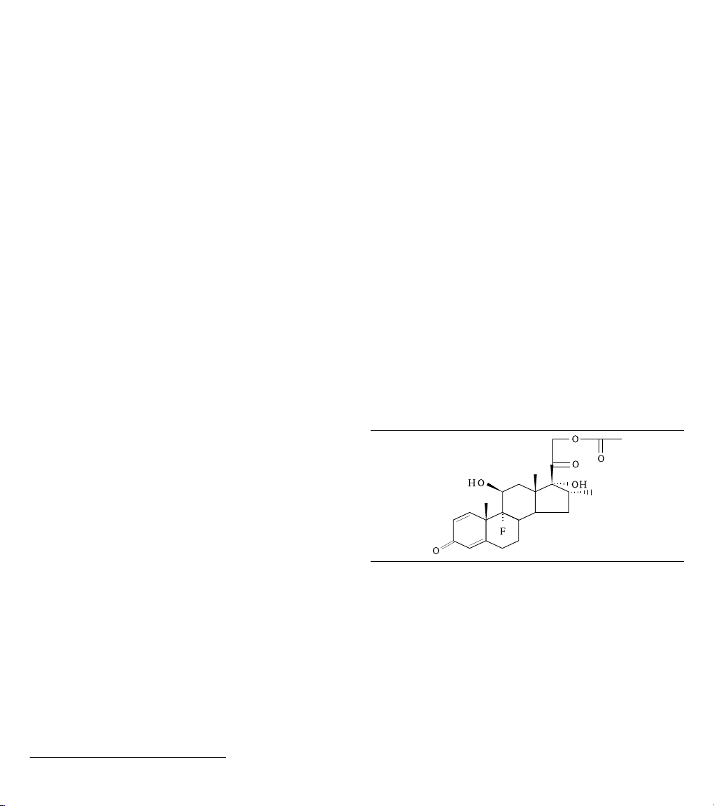
The active ingredient in the Model 4076 lead is dexamethasone
acetate. Dexamethasone acetate is 9-Fluoro-11β,
17,21-trihydroxy-16α-methylpregna-1,4-diene-3,20-dione
21-acetate. Dexamethasone acetate has a molecular formula of
C24H31FO6 and a molecular weight of 434.50. The MCRD
(Monolithic controlled release device) excipient is silicone. See
Figure 1 for the structural formula.
Figure 1.
The target dosage of dexamethasone acetate is 680 µg per lead.
3 Indications
The Model 4076 lead is designed to be used with a compatible
implantable pulse generator as part of a chronic cardiac pacing
system. The lead has application where implantable atrial or
ventricular, single chamber or dual chamber pacing systems are
indicated.
1
IS-1 refers to an International Connector Standard (ISO 5841-3) whereby pulse generators and leads so designated are assured of a basic mechanical fit.
3
Page 4

4 Contraindications
●
Use of a ventricular transvenous lead is contraindicated in
patients with tricuspid valvular disease.
●
Use of a ventricular transvenous lead is contraindicated in
patients with mechanical tricuspid heart valves.
●
Use of a steroid eluting lead is contraindicated in patients for
whom a single dose of 1.0 mg of dexamethasone acetate may
be contraindicated.
5 Warnings and precautions
Note: Medical procedure warnings and precautions that pertain to
the Medtronic implanted system are provided in the manual that is
packaged with the device or on the Medtronic Manual Library
website (www.medtronic.com/manuals).
Magnetic resonance imaging (MRI) – An MRI is a type of
medical imaging that uses magnetic fields to create an internal
view of the body. Do not conduct MRI scans on patients who have
this device or lead implanted. MRI scans may result in serious
injury, induction of tachyarrhythmias, or implanted system
malfunction or damage.
Line-powered and battery-powered equipment – An
implanted lead forms a direct current path to the myocardium.
During lead implant and testing, use only battery-powered
equipment or line-powered equipment specifically designed for
this purpose to protect against fibrillation that may be caused by
alternating currents. Line-powered equipment used in the vicinity
of the patient must be properly grounded. Lead connector pins
must be insulated from any leakage currents that may arise from
line-powered equipment.
Diathermy treatment (including therapeutic ultrasound) –
Diathermy is a treatment that involves the therapeutic heating of
body tissues. Diathermy treatments include high frequency, short
wave, microwave, and therapeutic ultrasound. Except for
therapeutic ultrasound, do not use diathermy treatments on
cardiac device patients. Diathermy treatments may result in
serious injury or damage to an implanted device and lead system.
Therapeutic ultrasound (including physiotherapy, high intensity
therapeutic ultrasound, and high intensity focused ultrasound), is
the use of ultrasound at higher energies than diagnostic
ultrasound to bring heat or agitation into the body. Therapeutic
ultrasound is acceptable if treatment is performed with a minimum
separation distance of 15 cm (6 in) between the applicator and the
implanted device and lead system, as long as the ultrasonic beam
is pointing away from the device and lead system.
Single use – The lead and accessories are for single use only.
Sterilization – Medtronic has sterilized the package contents
with ethylene oxide before shipment. This lead is for single use
only and is not intended to be resterilized.
Necessary hospital equipment – Keep external defibrillation
equipment nearby for immediate use during acute lead system
testing, the implant procedure, or whenever arrhythmias are
possible or intentionally induced during post-implant testing.
Inspecting the sterile package – Inspect the sterile package
with care before opening it.
●
If the seal or package is damaged, contact a Medtronic
representative.
●
Store at 25 °C (77 °F). Excursions from this storage
temperature are permitted in the range of 15 to 30 °C (59 to
86 °F). (See USP Controlled Room Temperature.) According
to USP excursion conditions, transient spikes up to 40 °C
(104 °F) are permitted as long as they do not exceed 24 hours.
●
Do not use the product after its expiration date.
Concurrent devices – Output pulses, especially from unipolar
devices, may adversely affect device sensing capabilities. If a
patient requires a separate stimulation device, either permanent
or temporary, allow enough space between the leads of the
separate systems to avoid interference in the sensing capabilities
of the devices. Previously implanted pulse generators and
implantable cardioverter defibrillators should generally be
explanted.
Steroid use – It has not been determined whether the warnings,
precautions, or complications usually associated with injectable
dexamethasone acetate apply to the use of this highly localized,
controlled-release lead. For a listing of potential adverse effects,
refer to the dexamethasone acetate manufacturer prescribing
information or the Physicians’ Desk Reference.
Steroid elution and exit block – Although the addition of steroid
to passive fixation leads has been shown to reduce pacing
thresholds in patients with a history of exit block, the frequency of
redevelopment of exit block was not statistically different between
the steroid eluting and the non-steroid eluting, active fixation,
screw-in leads in the Medtronic Model 4068 clinical trial.
Handling the steroid tip – Avoid reducing the amount of steroid
available before implanting the lead. Reducing the available
amount of steroid may adversely affect low-threshold
performance.
●
Do not allow the electrode surface to come in contact with
surface contaminants.
●
Do not wipe or immerse the electrode in fluid, except blood, at
the time of implant.
Handling the stylet – Handle the stylet with care at all times.
●
Curve the stylet before inserting it into the lead to achieve a
curvature at the lead’s distal end. Do not use a sharp object to
impart a curve to the distal end of the stylet.
●
Do not use excessive force or surgical instruments when
inserting the stylet into the lead.
●
Avoid overbending or kinking the stylet.
●
Use a new stylet when blood or other fluids accumulate on the
stylet. Accumulated blood or other fluids may damage the
lead or cause difficulty in passing the stylet into the lead.
Before inserting the lead – Use an anchoring sleeve with all
leads. Ensure that the anchoring sleeve is positioned close to the
lead connector pin. This will prevent inadvertent passage of the
sleeve into the vein. If wiping the lead is necessary prior to
insertion, ensure that the anchoring sleeve remains in position.
4
Page 5

Vessel and tissue damage – Use care when positioning the
lead. Avoid known infarcted or thin ventricular wall areas to
minimize the occurrence of perforation and dissection.
Handling a lead – Handle the lead with care at all times.
●
Do not implant the lead if it is damaged. Return the lead to a
Medtronic representative.
●
Protect the lead from materials that shed small particles such
as lint and dust. Lead insulators attract these particles.
●
Handle the lead with sterile surgical gloves that have been
rinsed in sterile water or a comparable substance.
●
Do not severely bend, kink, or stretch the lead.
●
Do not immerse the lead in mineral oil, silicone oil, or any other
liquid, except blood, at the time of implant.
●
Do not use surgical instruments to grasp the lead.
●
Do not force the lead if resistance is encountered during lead
passage.
Chronic repositioning or removal of a screw-in lead –
Proceed with extreme caution if a lead must be removed or
repositioned. Chronic repositioning or removal of screw-in
transvenous leads may not be possible because of blood or
fibrotic tissue development into the helix mechanism on the lead.
In most clinical situations, it is preferable to abandon unused leads
in place. Return all removed leads, unused leads, or lead sections
to Medtronic for analysis.
Note: If a helix electrode does not disengage from the
endocardium by rotating the connector pin, rotating the lead body
counterclockwise may withdraw the helix electrode and decrease
the possibility of damage to cardiovascular structures during
removal.
●
Lead removal may result in avulsion of the endocardium,
valve, or vein.
●
Lead junctions may separate, leaving the lead tip and bare
wire in the heart or vein.
●
Chronic repositioning of a lead may adversely affect the
low-threshold performance of a steroid lead.
●
An abandoned lead should be capped so that the lead does
not transmit electrical signals.
●
Severed leads should have the remaining lead end sealed
and the lead body sutured to adjacent tissue.
Connector compatibility – Although the lead conforms to the
IS-1 International Connector Standard, do not attempt to use the
lead with any device other than a commercially available
implantable pacing system with which it has been tested and
demonstrated to be safe and effective. The potential adverse
consequences of using such a combination may include, but are
not limited to, undersensing cardiac activity and failure to deliver
necessary therapy.
6 Drug information
6.1 Mechanism of action
Steroid suppresses the inflammatory response that is believed to
cause threshold rises typically associated with implanted pacing
electrodes. Dexamethasone acetate is a synthetic steroid of the
glucocorticoid family. Glucocorticoids have potent
anti-inflammatory actions via direct and indirect effects on major
inflammatory cells. Glucocorticosteroids bind to a cytoplasmic
glucocorticoid receptor as well as a membrane-bound receptor.
Binding to the cytoplasmic receptor leads to receptor activation
and translocation to the nucleus. The receptor interacts with
specific DNA sequences within the regulatory regions of affected
genes. Thus, glucocorticoids inhibit the production of multiple cell
factors that are critical in generating the inflammatory response.
6.2 Pharmacokinetics and metabolism
Pharmacokinetics – The pharmacokinetics (local drug levels
and systemic levels) of dexamethasone acetate and its
metabolites following implant were not evaluated in human clinical
trials. When delivered intra-muscularly, the lipid-soluble
dexamethasone acetate is slowly absorbed throughout the tissue.
Metabolism – The conversion of dexamethasone acetate to
dexamethasone occurs within hours. The dexamethasone
alcohol (dexamethasone) is the active glucocorticoid used in this
Medtronic lead. Steroid is applied via MCRD (Monolithic
controlled release device) and eluted to the tissue interface where
it will be used. The form of the steroid, whether it is a prodrug or the
pharmacologically active dexamethasone, is irrelevant, as the
steroid is directly present at the injury site to treat the
inflammation. Dexamethasone acetate is hydrolyzed into
dexamethasone, which is readily absorbed by the surrounding
tissue and body fluids. Glucocorticoids, when given systemically,
are eliminated primarily by renal excretion of inactive metabolites.
6.3 Mutagenesis, carcinogenicity, and reproductive toxicity
Mutagenesis, carcinogenicity, and reproductive toxicity –
The mutagenesis, carcinogenicity, and reproductive toxicity of the
CapSureFix Novus 4076 lead have not been evaluated. However,
the mutagenesis, carcinogenicity, and reproductive toxicity of
dexamethasone acetate have been evaluated previously.
Carcinogenesis, mutagenesis, and impairment of fertility –
No adequate studies have been conducted in animals to
determine whether corticosteroids have a potential for
carcinogenesis (tumor initiation or promotion). Dexamethasone
was genotoxic in assays for clastogenicity (including sister
chromatid exchange in human lymphocytes) but not in an assay
for mutagenicity in salmonella (Ames test). Adrenocorticoids have
been reported to increase or decrease the number and mobility of
spermatozoa in some patients.
6.4 Pregnancy
Pregnancy – Dexamethasone acetate has been shown to be
teratogenic in many species when given in doses equivalent to the
human dose. There are no adequate and well-controlled studies
in pregnant women. Dexamethasone acetate should be used
during pregnancy only if the potential benefit justifies the potential
risk to the fetus. Studies in mice, rats, and rabbits have shown that
adrenocorticoids increase the incidence of cleft palate, placental
insufficiency, and spontaneous abortions, and can decrease the
intrauterine growth rate.
5
Page 6

Nursing mothers – Systemically administered corticosteroids
appear in human milk and could suppress growth, interfere with
endogenous corticosteroid production, or cause other untoward
effects in nursing infants. Because of the potential for serious
adverse reactions in nursing infants from corticosteroids, a
decision should be made whether to discontinue nursing or to use
a non-steroidal lead, taking into account the importance of the
lead and the drug to the mother.
6.5 Lactation
Corticosteroids are secreted into human milk, and there is a
potential for serious adverse reactions. A decision should be
made whether to nurse or to discontinue the drug, taking into
account the importance of the drug to the mother. These potential
risks of corticosteroids should also be considered along with any
other steroidal therapy being received by the patient.
7 Adverse events
The potential adverse events related to the use of transvenous
leads include, but are not limited to, the following patient related
conditions that can occur when the lead is being inserted and/or
repositioned: valve damage (particularly in fragile hearts),
fibrillation and other arrhythmias, thrombolytic and air embolism,
cardiac perforation, heart wall rupture, cardiac tamponade,
muscle or nerve stimulation, pericarditis, pericardial rub, infection,
myocardial irritability, thrombosis, and pneumothorax.
Potential complications related to the lead and the programmed
parameters include, but are not limited to, the following:
Potential complication Symptom
Lead dislodgement Intermittent or contin-
Lead conductor or
helix electrode fracture or insulation failure
Threshold elevation
or exit block
a
Evidence indicates that there is a higher frequency of exit block in the
ventricle when using a screw-in lead. This should be considered when
selecting a screw-in lead for use in the ventricle.
a
uous loss of capture
or sensing
Intermittent or continuous loss of capture
or sensing
Loss of capture Adjust the pulse gen-
Potential acute/chronic complications associated with lead
placement include, but are not limited to, the following:
Corrective action to
be considered
Reposition the lead
Replace the lead. In
some cases with a
bipolar lead, the pulse
generator may be programmed to a unipolar configuration or the
lead may be unipolarized
erator output.
Replace or reposition
the lead
Implant technique
Forcing the lead
through the introducer
Use of too medial an
approach with venous
introducer resulting in
clavicle and first rib
binding
Puncturing the periosteum and/or tendon
when using subclavian introducer
approach
Advancing the lead
into the venous insertion site and/or
through the veins
without the stylet fully
inserted
Potential complication Corrective action
Screw electrode damage and/or insulation
damage
Conductor coil fracture, insulation damage
Conductor coil fracture, insulation damage
Tip distortion and/or
insulation perforation
Replace the lead
Replace the lead
Replace the lead
Replace the lead
In addition, prolonged implant procedures or multiple repositions
can allow blood or body fluids to build up on the helix electrode
mechanism. This may result in an increased number of rotations
required to extend or retract the helix electrode, which may
damage the lead.
8 Clinical trials
Note: Clinical studies were not performed on the 4076 lead due to
its similarity in design and function to the Model 5076 lead. The
clinical data collected for the Model 5076 lead therefore supports
the safety and efficacy claims for the 4076 lead and is included
here for reference purposes. The lead used for the Model 5076
clinical study did not include titanium nitride coated platinum alloy
tip and ring electrodes or an outer insulation of 55D polyurethane.
8.1 Summary
A multi-center, prospective, randomized control clinical study
conducted at 31 investigational sites (in the United States,
Europe, and Australia) compared the Model 5076 steroid eluting
lead to the Model 5068 steroid eluting lead. Both leads are silicone
extendible/retractable active fixation leads. The study design
included an initial phase where each implanting physician
implanted 2 patients with 5076 leads. This initial phase was then
followed by the randomized clinical study. During the study, 119
randomized dual chamber patients received Model 5076 leads,
119 randomized dual chamber patients received Model 5068
leads, and 99 dual chamber patients were included in the initial
phase.
Primary objectives: Compare the Model 5076 lead to the Model
5068 lead control lead for:
●
Survival from lead related complications and events at three
months
●
Pacing threshold performance at three months
6
Page 7

Compare the Model 5076 lead to the Model 5072 lead (historical
0.40
0.50
0.30
0.20
0.10
0.00
Note: Mean Plus/Minus 2 Standard Errors
Follow-Up Time in Weeks
Thresholds in ms
5068
Impedance in Ohms
Note: Mean Plus/Minus 2 Standard Errors
Follow-Up Time in Weeks
Follow-Up Time in Weeks
Sensing in mV
Note: Mean Plus/Minus 2 Standard Errors
Thresholds in ms
Note: Mean Plus/Minus 2 Standard Errors
Follow-Up Time in Weeks
control) for:
●
Sensing performance at three months
Results:The lead Model 5076 was found to be clinically
equivalent to the lead Model 5068 with respect to freedom from
lead related complications and total lead related events at three
months. The freedom from lead-related complications for the
Model 5076 is 97.6% (5 complications) and the Model 5068 is
94.7% (11 complications). The freedom from atrial lead related
events for the Model 5076 is 97.4% (3 events) and the Model 5068
is 94.7% (6 events). The freedom from ventricular lead related
events for the Model 5076 is 91.0% (10 events) and the Model
5068 is 86.7% (12 events). The 16 lead-related Model 5076
events (one was past three months, therefore it is not included in
the survival analysis) observed in the study are similar in kind and
rate to those commonly experienced with endocardial, active
fixation pacing leads.
There were five perforations reported with 5076 leads during the
initial phase of the study (2.5%), and one perforation reported in
the randomized portion of the study with 5076 leads (0.42%). No
perforations were reported with the 5068 control lead (0%).
Please refer to Chapter 7 of the technical manual for information
regarding risks associated with endocardial leads and the
Section 9.5 for recommended techniques to minimize tip pressure
during lead implant.
The electrical analysis included comparison of pulse width
thresholds and sensing performance. The mean Model 5076
pulse width thresholds measured at 2.5 V was found to be
clinically equivalent to the Model 5068 from implant to three
months post implant. The observed difference between the
ventricular leads (5076-5068) is -0.007 ms and the observed
difference between the atrial leads (5076-5068) is -0.009 ms. The
mean Model 5076 R/P-wave amplitudes were found to be
clinically equivalent to the mean Model 5072 (from previous
clinical study) R/P-wave amplitudes from implant to three months
post implant. The observed difference between R-wave
amplitudes (5072-5076) is 1.00 mV and -0.03 mV between
P-wave (5072-5076) amplitudes.
Figure 2. Atrial Pulse Width Thresholds at 2.5 V
Figure 3. Atrial bipolar impedance
Figure 4. Atrial P-wave sensing
Figure 5. Ventricular pulse width threshold at 2.5 V
7
Page 8

Figure 6. Ventricular bipolar impedance
Impedance in Ohms
Note: Mean Plus/Minus 2 Standard Errors
Follow-Up Time in Weeks
Note: Mean Plus/Minus 2 Standard Errors
Follow-Up Time in Weeks
Sensing in mV
1
Figure 7. Ventricular R-wave sensing
2. Leave the stylet inserted in the lead. Pull the stylet guide off
the connector pin and slide the stylet guide towards the stylet
knob.
3. Press both legs of the fixation tool together and place the
most distal hole of the fixation tool on the connector pin
(Figure 8).
Figure 8. Attachment of the fixation tool to the connector pin
1 Most distal hole of the fixation tool
4. While holding the lead as shown in Figure 9, and ensuring
that the stylet is fully inserted, rotate the tool clockwise until
the helix electrode is completely exposed (Figure 9).
Maximum helix electrode exposure reveals approximately 1
1/2 to 2 coils.
Figure 9. Rotating the fixation tool
9 Directions for use
Proper surgical procedures and sterile techniques are the
responsibility of the medical professional. The following
procedures are provided for information only. Some implant
techniques vary according to physician preference and the
patient’s anatomy or physical condition. Each physician must
apply the information in these instructions according to
professional medical training and experience.
9.1 Opening the package
Within the sterile field, open the sterile package and remove the
lead and accessories.
9.2 Verifying the mechanical functioning of the helix electrode
Before implant, verify the mechanical functioning of the helix
electrode, as described by the following:
1. Within the sterile field, remove the lead and the
8
accompanying stylets from the sterile packaging. The lead is
packaged with a stylet already inserted.
The recommended maximum number of rotations of the
fixation tool needed to extend or retract the helix electrode for
initial placement is stated in Section 10.1. The maximum
number of rotations depends on the particular lead model but
will increase or decrease proportionately for longer or shorter
leads. Any additional curvatures introduced to the stylet may
increase the number of rotations needed to extend or retract
the helix electrode.
Caution: Exceeding the recommended maximum number
of rotations required to extend or retract the helix electrode
may damage the lead.
5. Disconnect the fixation tool from the connector pin and
release the proximal end of the lead body. Allow several
seconds for the residual torque in the lead to be relieved.
6. After allowing for relief of the residual torque, reattach the
fixation tool and rotate it counterclockwise until the helix
electrode tip is retracted into the sheath.
Page 9

9.3 Using the stylet guide and stylets
1
The lead is packaged with the stylet guide attached to the
connector pin and a stylet already inserted.
A stylet provides additional stiffness and controlled flexibility for
maneuvering the lead into position. Stylets vary in stiffness to
accommodate a physician’s preference for lead and stylet
flexibility.
If the stylet guide has been removed, replace it by gently pushing
it as far as possible onto the connector pin (Figure 10). Insert a
stylet through the stylet guide and into the lead body.2 If a slight
curve is needed for the stylet, refer to the procedure in Section 9.5,
“Positioning the lead in the ventricle”, page 9.
Figure 10. Stylet guide attachment.
Caution: To avoid damage to the lead or body tissue, do not use
excessive force or surgical instruments to insert a stylet into the
lead. To avoid lead tip distortion, the stylet should always remain
fully inserted into the lead during lead introduction and while
advancing the lead, especially through tortuous veins, that may
cause the stylet to “back out” of the lead. When handling a stylet,
avoid overbending, kinking, or blood contact. If blood is allowed to
accumulate on a stylet, passage of the stylet into the lead may be
difficult.
9.4 Selecting an insertion site
Figure 11. Suggested insertion site
1 Suggested insertion site
Caution: When using a subclavian vein approach, avoid placing
the entry site in a location where the lead body can be clamped
between the clavicle and the first rib. A more lateral approach is
recommended to minimize the risk of first rib clavicular crush.
Clamping the lead may eventually cause the conductor to fracture,
may cause damage to the insulation, or may cause other damage
to the lead. Certain anatomical abnormalities, such as thoracic
outlet syndrome, may also precipitate clamping of the lead.
Use fluoroscopy to facilitate accurate lead placement.
9.5 Positioning the lead in the ventricle
Caution: Use care when handling the lead during positioning.
●
Do not severely bend, kink, or stretch the lead.
●
Do not use surgical instruments to grasp the lead or connector
pin.
1. Insert the tapered end of a vein lifter into the incised vein and
gently push the lead tip underneath and into the vein
(Figure 12). A vein lifter facilitates lead insertion.
Figure 12. Using the vein lifter
The lead may be inserted by venotomy through several different
venous routes, including the right or left cephalic vein, other
subclavian branches, or the external or internal jugular vein. The
lead may also be inserted into a subclavian vein through a
percutaneous lead introducer. Select the desired entry site
(Figure 11).
2. Advance the lead into the right atrium using a straight stylet to
facilitate movement through the veins.
2
If additional stylets are needed, Medtronic recommends using the same type of Medtronic stylet that is packaged with the lead.
9
Page 10

3. Advance the lead through the tricuspid valve. Replacing the
straight stylet with a gently curved stylet may add control in
maneuvering the lead through the tricuspid valve. Advance
the lead directly through the tricuspid valve, or project the
lead tip against the lateral atrial wall and back the curved
portion of the lead body through the tricuspid valve until the
lead tip enters the ventricle.
4. Position the lead in the ventricle using the following
techniques. Accurate positioning of the electrode is essential
for stable pacing.
Caution: If there is reason to believe the patient has an
unusually thin wall at the apex of the right ventricle, the
implanter may wish to consider another site for placement of
the lead.
Caution: If placing the lead in or near the right ventricular
apex, use caution if passing the distal end of the lead directly
from the valve to the apex. This technique may result in
excessive tip pressure.
Caution: If an awake patient feels a twinge of pain, this may
be an early sign of perforation.
Using one of the following techniques may help minimize
transmission of pressure directly toward the tip of the lead:
●
Partially withdraw the stylet so that the stylet tip is
proximal to the electrode ring while positioning the lead,
to minimize tip stiffness. The stylet can then be gently
advanced to the tip of the lead before securing the
electrode in the endocardium.
●
A curved stylet may be used during positioning to
minimize direct pressure on the apex.
●
Using a curved stylet, or partially withdrawing the stylet
to allow the lead to be carried by blood flow, the lead may
be curved up toward the outflow tract and then allowed to
fall gently into position near the apex by pulling back on
the lead body.
Use fluoroscopy (lateral position) to ensure that the tip is not
in a retrograde position or is not lodged in the coronary sinus.
5. After placing the lead in a satisfactory position, extend the
helix electrode by following the procedure in Section 9.7.
9.6 Positioning the lead in the atrium
Caution: Use care when handling the lead during positioning:
●
Do not severely bend, kink, or stretch the lead.
●
Do not use surgical instruments to grasp the lead or connector
pin.
The following procedure is suggested for atrial placement of the
lead:
1. Insert the tapered end of a vein lifter into the incised vein and
gently push the lead tip underneath and into the vein
(Figure 13). A vein lifter facilitates lead insertion.
Figure 13. Using the vein lifter
2. Advance the lead into the right atrium or the inferior vena
cava using a straight stylet to facilitate movement through the
veins. After the lead tip is passed into the atrium or inferior
vena cava, replace the straight stylet with a gently curved
stylet or the J-shaped stylet supplied with the lead.
3. Direct the lead tip into an appropriate position. Accurate
positioning of the helix electrode is essential for stable
pacing and sensing.
Generally, a satisfactory position has the lead tip situated
against the atrial endocardium in or near the apex of the
appendage. As viewed on the fluoroscope (A-P view), the
lead tip points medially and forward toward the left atrium. A
successful position is usually achieved with an anterior,
medial, or lateral tip location.
Caution: An awake patient who feels a twinge of pain may
indicate an early sign of perforation.
4. After placing the lead tip in a satisfactory position, extend the
helix electrode by following the procedure in Section 9.7.
9.7 Securing the helix electrode into the endocardium
The following procedure is recommended for helix electrode
fixation:
1. Leave the stylet inserted in the lead. Pull the stylet guide off
the connector pin and slide the stylet guide towards the stylet
knob.
2. Press both legs of the fixation tool together and place the
most distal hole of the fixation tool on the connector pin
(Figure 8).
3. Press the lead tip against the endocardium using the
appropriate technique:
●
Ventricular placement: Press the lead tip against the
endocardium by gently pushing the stylet and lead at the
vein entry site.
●
Atrial placement: With the lead tip advanced into the
atrium and a J-shaped or gently curved stylet in the lead,
press the lead tip against the endocardium by gently
pulling the stylet and the lead at the vein entry site.
10
Page 11

4. Rotate the fixation tool clockwise until the helix electrode is
Retracted
Extended
completely exposed (Figure 9). Maximum electrode
exposure reveals approximately 1½ to 2 coils of the helix.
The maximum number of rotations of the fixation tool needed
to extend or retract the helix electrode for initial placement is
stated in the section Section 10.1, “Specifications
(nominal)”, page 14.” The maximum number of rotations
depends on the particular lead model but will increase or
decrease proportionately for longer or shorter leads.
Caution: Prolonged implant procedures or multiple
repositionings can allow blood or body fluids to build up on
the helix electrode mechanism. This may result in an
increased number of rotations required to extend or retract
the helix electrode.
Caution: Exceeding the number of rotations required to
extend or retract the helix electrode may damage the lead.
5. Use fluoroscopy to verify helix electrode extension.
Extension of the space between the indicator ring (A) and the
drive mechanism (B) implies complete exposure of the helix
electrode (Figure 14).
Figure 14. Possible views of the electrode
6. Disconnect the fixation tool from the connector pin and
release the proximal end of the lead body. Allow several
seconds for the residual torque in the lead to be relieved.
7. Carefully and partially, withdraw the stylet.
8. Verify that the helix electrode is affixed.
a. For a lead placed in the ventricle: Gently pull back on
the lead and check for resistance to verify affixation. A
properly affixed helix electrode will remain in position. If
the helix electrode is not properly affixed, the lead tip may
become loose in the right ventricle.
If the helix electrode does not remain affixed, it may be
possible to fixate it during a subsequent attempt by
rotating the whole lead body clockwise approximately
one rotation after allowing the residual torque to be
relieved in step 4. Caution is recommended if turning of
the whole lead body is employed during or after fixation of
the helix electrode.
b. For a lead placed in the atrium: Use frontal
fluoroscopy to check for lateral movement of the atrial tip,
which reflects atrial and ventricular contractions. Check
for constancy of the movement by rotating the lead body
(up to 180 degrees in either direction) while the patient
breathes deeply. Poor fixation is suspected when tip
movement seems random.
After the lead tip is fixated, allow lead slack to build up in
the atrium. Lead slack helps prevent tip dislodgement.
Enough slack is present if, under fluoroscopy, the lead
assumes an “L” shape during deep inspiration. Avoid
excessive slack buildup that may cause the loop of the
lead to drop near the tricuspid valve.
9. If repositioning is required, reattach and rotate the fixation
tool counterclockwise until the helix electrode is withdrawn.
Use fluoroscopy to verify withdrawal. Again, as previously
stated for final positioning of a lead placed in the ventricle,
avoid transmission of pressure directly toward the tip of the
lead to prevent the lead from being pushed directly into the
apex.
Caution: Do not rotate the fixation tool more than the number
of rotations required to fully retract the helix electrode.
10. Remove the stylet guide and stylet completely. When
removing the stylet guide, grip the lead firmly just below the
connector pin; this will help prevent possible lead
dislodgement.
11. Obtain final electrical measurements.
9.8 Taking electrical measurements
Attach a surgical cable to the connector pin for taking electrical
measurements.
Note: A notch in the stylet guide allows connection of a surgical
cable for electrical measurement.
Low stimulation thresholds and adequate sensing of intracardiac
signal amplitudes indicate satisfactory lead placement.
Medtronic recommends using a voltage source such as a pacing
system analyzer for obtaining electrical measurements.
A low stimulation threshold provides for a desirable safety margin,
allowing for a possible rise in thresholds that may occur within 2
months following implantation.
Adequate sensing amplitudes ensure that the lead is properly
sensing intrinsic cardiac signals. Minimum signal requirements
depend on the pulse generator’s sensitivity capabilities.
Acceptable acute signal amplitudes for the lead must be greater
than the minimum pulse generator sensing capabilities including
an adequate safety margin to account for lead maturity.
11
Page 12

Table 1. Recommended electrical measurements at implant when using a pacing system analyzer
Ventricle Atrium
Maximum acute stimulation thresholds
Minimum acute sensing amplitudes 5.0 mV 2.0 mV
a
At pulse duration setting of 0.5 ms.
a
1.0 V
3.0 mA
1.5 V
4.5 mA
Initial electrical measurements may deviate from the
recommendations because of acute cellular trauma. If this occurs,
wait 5 to 15 minutes and repeat the testing procedure. Values may
vary depending upon lead type, pulse generator settings, cardiac
tissue condition, and drug interactions.
If electrical measurements do not stabilize to acceptable levels, it
may be necessary to reposition the lead and to repeat the testing
procedure.
Check for diaphragmatic stimulation by pacing at 10 V and
observing on fluoroscopy whether the diaphragm contracts with
each paced stimulus. If diaphragmatic pacing occurs, reduce the
voltage until a diaphragmatic pacing threshold is determined. If
the diaphragmatic threshold is less than the required
programmed pacing output, the lead should be repositioned.
Pacing impedance (or resistance) is used to assess pulse
generator function and lead integrity during routine pulse
generator patient follow-up and to assist in troubleshooting
suspected lead failures. (Additional troubleshooting procedures
include ECG analysis, visual inspection, measurement of
thresholds, and electrogram characteristics.)
Pacing impedance values are affected by many factors including
lead position, electrode size, conductor design and integrity,
insulation integrity, and the patient’s electrolyte balance. Apparent
pacing impedance is significantly affected by the measurement
technique; therefore, comparison of pacing impedance should be
done using consistent methods of measurement and equipment.
An impedance higher or lower than the typical value is not
necessarily a conclusive indication of lead failure. Other causes
must be considered as well. Before reaching a conclusive
diagnosis, the full clinical picture must be considered: pacing
artifact size and morphology changes in 12-lead analog ECGs,
muscle stimulation with bipolar leads, sensing and/or capture
problems, patient symptoms, and pulse generator characteristics.
In addition to measuring impedance values, non-invasive blood
pressure monitoring and the use of echocardiographic methods
may be valuable during implantation.
Recommendations for clinically monitoring and evaluating leads
in terms of impedance characteristics are given as follows.
For pulse generators with telemetry readout of impedance:
●
Routinely monitor and record impedance values, at implant
and follow-ups, using consistent output settings. (Be aware
that impedance values may be different at different
programmable output settings [for example, pulse width or
pulse amplitude] of the pulse generator or pacing system
analyzer.)
●
Establish a baseline chronic impedance value once the
impedance has stabilized, generally within 6 to 12 months
after implant.
●
Monitor for significant impedance changes and abnormal
values.
●
Where impedance abnormalities occur, closely monitor the
patient for indications of pacing and sensing problems. The
output settings used for measuring impedance should be the
same as that used for the original measurements.
●
For patients at high risk, such as pulse generator dependent
patients, physicians may want to consider further action, such
as: increased frequency of monitoring, provocative
maneuvers, and ambulatory ECG monitoring.
For pulse generators without telemetry:
●
Record impedance value at implant. Also record the
measurement device, its output settings, and the procedure
used.
●
At the time of pulse generator replacement, if pacing analyzer
system-measured impedance is abnormal, carefully evaluate
lead integrity (including thresholds and physical appearance)
and patient condition before electing to reuse the lead.
●
Bear in mind that impedances below 250 Ω may result in
excessive battery current drain, which may seriously
compromise pulse generator longevity, regardless of lead
integrity.
For more information on obtaining electrical measurements,
consult the technical manual supplied with the testing device.
9.9 Anchoring the lead
Note: The anchoring sleeve contains a radiopaque substance,
which allows visualization of the anchoring sleeve on a standard
x-ray and may aid in follow-up exams.
Use the triple groove anchoring sleeve to secure the lead and to
protect the lead insulation and conductor coil from damage
caused by tight ligatures (Figure 15, Figure 16, and Figure 17).
Anchor the lead with nonabsorbable sutures.
Caution: Tabs on anchoring sleeves are provided to minimize the
possibility of the sleeve entering the vein. Do not remove the tabs
(Figure 15). If using a large diameter percutaneous lead
introducer (PLI) sheath, extreme care should be taken to prevent
passage of the anchoring sleeve into the PLI lumen and/or the
venous system.
12
Page 13

Figure 15. Triple groove anchoring sleeve with tabs.
1
1 Anchoring sleeve tab
With a triple groove anchoring sleeve, generally 2 or 3 of the
grooves may be used with the following procedure (Figure 16 or
Figure 17).
The triple groove anchoring sleeve is situated at the connector
end of the lead. Partially insert the anchoring sleeve into the vein.
Use the most distal suture groove to secure the anchoring sleeve
to the vein.
Use the middle groove to secure the anchoring sleeve to the fascia
and lead. First, create a base by looping a suture through the
fascia underneath the middle groove and tying a knot. Continue by
firmly wrapping the suture around the middle groove and tying a
second knot.
Use the third and most proximal groove to secure the anchoring
sleeve to the lead body.
Alternatively, only 2 of the 3 grooves may be used on the triple
groove anchoring sleeve to tie down the lead. In that case, follow
the anchoring procedure for the distal and middle groove
(Figure 17).
Caution: Do not use the anchoring sleeve tabs for suturing.
Figure 16. Triple groove anchoring sleeve secured to the lead and
fascia using 3 grooves.
(Figure 18). During anchoring, take care to avoid dislodging the
lead tip.
Figure 18. Do not secure the sutures too tightly and do not tie a suture to the lead body.
9.10 Connecting the lead to the pulse generator
Connect the lead to the pulse generator according to the
instructions in the pulse generator manual.
Caution: Always remove the stylet before connecting the lead to
the pulse generator. Failure to remove the stylet may result in lead
failure.
Caution: To prevent undesirable twisting of the lead body, wrap
the excess lead length loosely under the pulse generator and
place both into the subcutaneous pocket (Figure 19).
Figure 19. While rotating the device, loosely wrap the excess lead length around the device.
Caution: When placing the pulse generator and lead into the
subcutaneous pocket:
●
Do not coil the lead. Coiling the lead can twist the lead body
and may result in lead dislodgment (Figure 20).
●
Do not grip the lead or pulse generator with surgical
instruments.
Figure 20. Do not coil or twist the lead body.
Figure 17. Triple groove anchoring sleeve secured to the lead and
fascia using 2 grooves.
Tie the sutures securely but gently to prevent damage to the triple
groove anchoring sleeve.
Caution: Do not secure the ligatures so tightly that they damage
the vein or lead. Do not tie a ligature directly to the lead body
9.11 Post-implant evaluation
After implant, monitor the patient’s electrocardiogram until the
patient is discharged. If a lead dislodges, it usually occurs during
the immediate postoperative period.
Recommendations for verifying proper lead positioning include
x-rays and pacing and sensing thresholds taken at pre-hospital
discharge, 3 months after implant, and every 6 months thereafter.
13
Page 14

In the event of a patient death, explant all implanted leads and
devices and return them to Medtronic with a completed Product
Information Report form. Call the appropriate phone number on
the back cover if there are any questions on product handling
procedures.
10 Specifications
10.1 Specifications (nominal)
Parameter Model 4076
Type Bipolar
Chamber Ventricle/Atrium
Fixation Screw-in
Length 20–110 cm
Connector IS-1 BI
Materials Conductor: MP35N nickel alloy
Outer Insula-
Inner Insula-
Connector pin: Stainless steel
Connector
Electrode materials
Electrode surface
area
Tip to ring spacing 10 mm
Diameter Lead body: 1.9 mm
Lead introducer (recommended size)
without guide
with guide
Helix length 1.8 mm (fully extended)
Lead conductor
resistance
Steroid Dexamethasone acetate
Amount of steroid 680 µg (target dosage)
Unipolar: 33.5 Ω (58 cm)
Bipolar: 61.4 Ω (58 cm)
55D polyurethane
tion
Treated silicone rubber
tion:
Stainless steel
ring:
Helix: Titanium nitride coated platinum
alloy
Ring: Titanium nitride coated platinum
alloy
Helix: 4.2 mm
Ring: 22 mm
wire:
wire:
2
2
2.3 mm (7 French)
3.0 mm (9 French)
Table 2. Maximum number of rotations to extend or retract the helix electrode
Straight stylet Lead length J-shaped stylet
10 45 cm 15
11 52 cm 17
12 58 cm 18
14 65 cm —
18 85 cm —
23 110 cm —
11 Medtronic warranty
For complete warranty information, see the accompanying
warranty document.
12 Service
Medtronic employs highly trained representatives and engineers
located throughout the world to serve you and, upon request, to
provide training to qualified hospital personnel in the use of
Medtronic products. Medtronic also maintains a professional staff
to provide technical consultation to product users. For more
information, contact your local Medtronic representative, or call or
write Medtronic at the appropriate telephone number or address
listed on the back cover.
The following table lists the recommended maximum rotations
required to extend or retract the helix electrode for initial
placement.
14
Page 15

Page 16

Medtronic, Inc.
*M955297A001*
710 Medtronic Parkway
Minneapolis, MN 55432
USA
www.medtronic.com
+1 763 514 4000
Medtronic USA, Inc.
Toll-free in the USA (24-hour technical consultation for
physicians and medical professionals)
Bradycardia: +1 800 505 4636
Tachycardia: +1 800 723 4636
Europe/Middle East/Africa
Medtronic International Trading Sàrl
Route du Molliau 31
Case Postale 84
CH-1131 Tolochenaz
Switzerland
+41 21 802 7000
Technical manuals
www.medtronic.com/manuals
© 2015 Medtronic, Inc.
M955297A001 C
2015-09-23
 Loading...