

Page 1

CAPSURE SENSE® 4074
Steroid-eluting, bipolar, implantable, tined, ventricular, transvenous lead
Technical Manual
Caution: Federal law (USA) restricts this device to sale by or on the order of a physician.
Page 2

The following list includes trademarks or registered trademarks of Medtronic in the United States and possibly in other countries.
All other trademarks are the property of their respective owners.
CapSure, CapSure Sense, Capture Management, Medtronic
Page 3

Contents
1 Description 3
2 Drug component description 3
3 Indications 3
4 Contraindications 3
5 Warnings and precautions 4
6 Drug information 5
7 Potential adverse events 6
8 Clinical data 6
9 Directions for use 9
10 Specifications (nominal) 12
11 Medtronic warranty 14
12 Service 14
1 Description
The Medtronic CapSure Sense Model 4074 steroid-eluting,
bipolar, implantable, tined, ventricular, transvenous lead is
designed for ventricular pacing and sensing. The platinum alloy
tip and ring electrodes feature a high-active surface area of
titanium nitride microstructure. This electrode configuration
contributes to low polarization.
The tip electrode of the lead incorporates a steroid-eluting plug
containing dexamethasone acetate. The tip electrode contains a
target nominal dosage of 272 µg of dexamethasone. Upon
exposure to body fluids, the steroid elutes from the electrode.
The lead is designed to provide low chronic pacing thresholds via
steroid treatment of cardiac tissue near the lead tip. Steroid
suppresses the inflammatory response that is believed to cause
threshold rises typically associated with implanted pacing
electrodes.
The lead features four polyurethane tines near the electrode tip,
MP35N nickel alloy conductors, polyurethane outer insulation,
silicone inner insulation, and an IS-1 Bipolar (BI)1 lead connector.
1.1 Package contents
Leads and accessories are supplied sterile. Each package
contains the following items:
●
1 lead with anchoring sleeve, stylet, and stylet guide
●
1 vein lifter
●
extra stylets
●
product documentation
1.2 Accessory descriptions
Dispose of all single-use accessories according to local
environmental requirements.
Anchoring sleeve – An anchoring sleeve secures the lead to
prevent it from moving and protects the lead insulation and
conductors from damage caused by tight sutures.
Stylet – A stylet provides additional stiffness and controlled
flexibility for maneuvering the lead into position. Each stylet knob
is labeled with the stylet diameter and length.
Stylet guide – A stylet guide facilitates stylet insertion into the
lead.
Vein lifter – A vein lifter facilitates lead insertion into a vein.
2 Drug component description
The active ingredient in the Model 4074 lead is dexamethasone
acetate. Dexamethasone acetate is 9-Fluoro-11β,
17,21-trihydroxy-16α-methylpregna-1,4-diene-3,20-dione
21-acetate. Dexamethasone acetate has a molecular formula of
C24H31FO6 and a molecular weight of 434.50. The MCRD
excipient is silicone. See Figure 1 for the structural formula.
Figure 1.
The target dosage of dexamethasone acetate is 272 µg per lead.
3 Indications
The Model 4074 implantable, ventricular, transvenous lead has
application where implantable ventricular single-chamber or
dual-chamber pacing systems are indicated. The lead is intended
for pacing and sensing in the ventricle.
4 Contraindications
●
Use of ventricular transvenous leads is contraindicated in
patients with tricuspid valvular disease.
●
Use of ventricular transvenous leads is contraindicated in
patients with mechanical tricuspid heart valves.
●
Use of steroid eluting transvenous leads is contraindicated in
patients for whom a single dose of 272 µg dexamethasone
acetate may be contraindicated.
1
IS-1 BI refers to an International Connector Standard (ISO 5841-3) whereby pulse generators and leads so designated are assured of a basic mechanical fit.
3
Page 4

5 Warnings and precautions
Note: Medical procedure warnings and precautions that pertain
to the Medtronic implanted system are provided in the manual that
is packaged with the device or on the Medtronic Manual Library
website (www.Medtronic.com/manuals).
Line-powered and battery-powered equipment – An
implanted lead forms a direct current path to the myocardium.
During lead implant and testing, use only battery-powered
equipment or line-powered equipment specifically designed for
this purpose to protect against fibrillation that may be caused by
alternating currents. Line-powered equipment used in the vicinity
of the patient must be properly grounded. Lead connector pins
must be insulated from any leakage currents that may arise from
line-powered equipment.
Diathermy treatment (including therapeutic ultrasound) –
Diathermy is a treatment that involves the therapeutic heating of
body tissues. Diathermy treatments include high frequency, short
wave, microwave, and therapeutic ultrasound. Except for
therapeutic ultrasound, do not use diathermy treatments on
cardiac device patients. Diathermy treatments may result in
serious injury or damage to an implanted device and leads.
Therapeutic ultrasound is the use of ultrasound at higher energies
than diagnostic ultrasound to bring heat or agitation into the body.
Therapeutic ultrasound is acceptable if treatment is performed
with a minimum separation distance of 15 cm (6 in) between the
applicator and the implanted device and leads.
Vessel and tissue damage – Use care when positioning the
lead. Avoid known infarcted or thin ventricular wall areas to
minimize the occurrence of perforation and dissection.
Single use – The lead and accessories are for single use only.
Inspecting the sterile package – Inspect the sterile package
with care before opening it.
●
If the seal or package is damaged, contact a Medtronic
representative.
●
Store at 25 °C (77 °F). Excursions from this storage
temperature are permitted in the range of 15 to 30 °C (59 to
86 °F). (See USP Controlled Room Temperature.) According
to USP excursion conditions, transient spikes up to 40 °C
(104 °F) are permitted as long as they do not exceed 24 hours.
●
Do not use the product after its expiration date.
Sterilization – Medtronic has sterilized the package contents
with ethylene oxide before shipment. This lead is for single use
only and is not intended to be resterilized.
Steroid use – It has not been determined whether the warnings,
precautions, or complications usually associated with injectable
dexamethasone acetate apply to the use of this highly localized,
controlled-release lead. For a list of potential adverse effects,
refer to the Physicians’ Desk Reference.
Handling the steroid tip – Avoid reducing the amount of steroid
available before implanting the lead. Reducing the available
amount of steroid may adversely affect low-threshold
performance.
●
Do not allow the electrode surface to come in contact with
surface contaminants.
●
Do not wipe or immerse the electrode in fluid, except blood,
at the time of implant.
Handling a tined lead – Handle the lead with care at all times.
●
Do not implant the lead if it is damaged. Return the lead to a
Medtronic representative.
●
Protect the lead from materials that shed small particles such
as lint and dust. Lead insulators attract these particles.
●
Handle the lead with sterile surgical gloves that have been
rinsed in sterile water or a comparable substance.
●
Do not severely bend, kink, or stretch the lead.
●
Do not immerse the lead in mineral oil, silicone oil, or any other
liquid, except blood, at the time of implant.
●
Do not use surgical instruments to grasp the lead.
●
Do not force the lead if resistance is encountered during lead
passage.
Handling the stylet – Handle the stylet with care at all times.
●
Curve the stylet before inserting it into the lead to achieve a
curvature at the lead’s distal end. Do not use a sharp object
to impart a curve to the distal end of the stylet.
●
Do not use excessive force or surgical instruments when
inserting the stylet into the lead.
●
Avoid overbending or kinking the stylet.
●
Use a new stylet when blood or other fluids accumulate on
the stylet. Accumulated blood or other fluids may damage the
lead or cause difficulty in passing the stylet into the lead.
Necessary hospital equipment – Keep external defibrillation
equipment nearby for immediate use during acute lead system
testing, the implant procedure, or whenever arrhythmias are
possible or intentionally induced during post-implant testing.
Magnetic resonance imaging (MRI) – An MRI is a type of
medical imaging that uses magnetic fields to create an internal
view of the body. Do not conduct MRI scans on patients who have
this device or lead implanted. MRI scans may result in serious
injury, induction of tachyarrhythmias, or implanted system
malfunction or damage.
Concurrent devices – Output pulses, especially from unipolar
devices, may adversely affect device sensing capabilities. If a
patient requires a separate stimulation device, either permanent
or temporary, allow enough space between the leads of the
separate systems to avoid interference in the sensing capabilities
of the devices. Previously implanted pulse generators and
implantable cardioverter defibrillators should generally be
explanted.
Chronic repositioning or removal of a tined lead – Proceed
with extreme caution if a lead must be removed or repositioned.
Chronic repositioning or removal of tined transvenous leads may
be difficult because of fibrotic tissue development on the lead. In
most clinical situations, it is preferable to abandon unused leads
4
Page 5

in place. Return all removed leads, unused leads, or lead sections
to Medtronic for analysis.
●
Lead removal may result in avulsion of the endocardium,
valve, or vein.
●
Lead junctions may separate, leaving the lead tip and bare
wire in the heart or vein.
●
Chronic repositioning of a lead may adversely affect a steroid
lead’s low-threshold performance.
●
An abandoned lead should be capped so that the lead does
not transmit electrical signals.
●
Severed leads should have the remaining lead end sealed
and the lead body sutured to adjacent tissue.
Connector compatibility – Although the lead conforms to the
IS-1 International Connector Standard, do not attempt to use the
lead with any device other than a commercially available
implantable pacing system with which it has been tested and
demonstrated to be safe and effective. The potential adverse
consequences of using such a combination may include, but are
not limited to, undersensing cardiac activity and failure to deliver
necessary therapy.
6 Drug information
6.1 Mechanism of action
Steroid suppresses the inflammatory response that is believed to
cause threshold rises typically associated with implanted pacing
electrodes. Dexamethasone acetate is a synthetic steroid of the
glucocorticoid family. Glucocorticoids have potent
anti-inflammatory actions via direct and indirect effects on major
inflammatory cells. Glucocorticosteroids bind to a cytoplasmic
glucocorticoid receptor as well as a membrane-bound receptor.
Binding to the cytoplasmic receptor leads to receptor activation
and translocation to the nucleus. The receptor interacts with
specific DNA sequences within the regulatory regions of affected
genes. Thus, glucocorticoids inhibit the production of multiple cell
factors that are critical in generating the inflammatory response.
6.2 Pharmacokinetics and metabolism
Pharmacokinetics – The pharmacokinetics (local drug levels
and systemic levels) of dexamethasone acetate and its
metabolites following implant were not evaluated in human
clinical trials. When delivered intra-muscularly, the lipid-soluble
dexamethasone acetate is slowly absorbed throughout the
tissue.
Metabolism – The conversion of dexamethasone acetate to
dexamethasone occurs within hours. The dexamethasone
alcohol (dexamethasone) is the active glucocorticoid used in this
Medtronic lead. Steroid is applied via MCRD (Monolithic
controlled release device) and eluted to the tissue interface where
it will be used. The form of the steroid, whether it is a prodrug or
the pharmacologically active dexamethasone, is irrelevant, as the
steroid is directly present at the injury site to treat the
inflammation. Dexamethasone acetate is hydrolyzed into
dexamethasone, which is readily absorbed by the surrounding
tissue and body fluids. Glucocorticoids, when given systemically,
are eliminated primarily by renal excretion of inactive metabolites.
6.3 Mutagenesis, carcinogenicity, and reproductive toxicity
The mutagenesis, carcinogenicity, and reproductive toxicity of
the Model 4074 lead have not been evaluated. However, the
mutagenesis, carcinogenicity, and reproductive toxicity of
dexamethasone acetate have previously been evaluated.
Mutagenesis – Genotoxicity evaluation of dexamethasone was
undertaken using in vitro and in vivo assays. Analyses of
chromosomal aberrations, sister-chromatid exchanges in human
lymphocytes, and micronuclei and sister-chromatid exchanges in
mouse bone marrow showed dexamethasone to be capable of
attacking the genetic material. However, the Ames/Salmonella
assay, both with and without S9 mix, did not show any increase
His+ revertants.
Carcinogenicity – Although adequate and well-controlled
animal studies have not been performed on Dexamethasone
acetate, use in humans has not shown an increase in malignant
disease.
Reproductive Toxicity – Adrenocorticoids have been reported
to increase or decrease the number and motility of spermatozoa.
However, it is not known whether reproductive capacity in
humans is adversely affected.
Pregnancy – Adrenocorticoids cross the placenta. Although
adequate studies have not been performed in humans, there is
some evidence that pharmacologic doses of adrenocorticoids
may increase the risk of placental insufficiency, decreased birth
weights or stillbirth. However, tetrogenic effects in humans have
not been confirmed.
Infants born to mothers who have received substantial doses of
adrenocorticoids during pregnancy should be carefully observed
for signs of hypoadrenalism and replacement therapy
administered as required.
Prenatal administration of dexamethasone to the mother to
prevent respiratory distress syndrome in the premature neonate
has not been shown to affect the child’s growth or development
adversely. Physiologic replacement doses of adrenocorticoids
administered for treatment of adrenal insufficiency are also
unlikely to adversely affect the fetus or neonate. Animal studies
have shown that adrenocorticoids increase the instance of cleft
palate, placental insufficiency, spontaneous abortions, and
intrauterine growth retardation.
Lactation – Problems in humans have not been documented.
Adrenocorticoids are excreted in breast milk and may cause
unwanted defects such as growth suspension and inhibition of
endogenous steroid production in the infant.
5
Page 6

7 Potential adverse events
The potential complications (listed in alphabetical order) related
to the use of transvenous leads include, but are not limited to, the
following patient-related conditions that can occur when the lead
is being inserted or repositioned:
●
cardiac perforation
●
cardiac tamponade
●
fibrillation and other arrhythmias
●
heart wall rupture
●
infection
●
muscle or nerve stimulation
●
pericardial rub
●
pneumothorax
●
thrombolytic and air embolism
●
thrombosis
●
valve damage (particularly in fragile hearts)
Other potential complications related to the tined lead and the
programmed parameters include, but are not limited to, the
complications listed in the following table. Symptoms of the
following potential complications include loss of capture or
intermittent or continuous loss of capture or sensing2:
Complication
Lead dislodgement Reposition the lead.
Lead conductor fracture or insulation failure
Threshold elevation or exit block Adjust the implantable device out-
Potential acute or chronic complications associated with tined
lead placement that may require lead replacement to correct
include, but are not limited to, the following:
Implant technique Potential complication
Forcing the lead through the introducer
Use of too medial of an approach
with venous introducer resulting in
clavicle and first rib binding
Corrective action to be considered
Replace the lead. In some cases
with a bipolar lead, the implantable
device may be programmed to a
unipolar configuration or the lead
may be unipolarized.
put. Replace or reposition the lead.
Electrode damage, tine damage,
insulation damage
Conductor coil fracture, insulation
damage
Implant technique Potential complication
Puncturing the periosteum and/or
tendon when using subclavian
introducer approach
Advancing the lead into the
venous insertion site and/or
through the veins without the stylet
fully inserted
Conductor coil fracture, insulation
damage
Tip distortion, insulation perforation
8 Clinical data
A multi-center, prospective, nonrandomized, historically
controlled clinical study conducted at 19 investigational sites in
the United States and 4 investigational sites in Canada compared
the Model 4074 and Model 4574 pacing leads to the Medtronic
Model 4092, Model 4592, and Model 5072 pacing leads
(historical control leads).
Clinical experience from the market released Model 4092 and
Model 4592 leads was used as the historical control for the safety,
pacing threshold, ventricular sensing, and impedance objectives.
The market released Model 5072 lead was used as the historical
control for the atrial sensing objective because it has a tip to ring
spacing of 10 mm which is similar to the 9 mm tip to ring spacing
in the Model 4574 lead.
During the study, 132 patients received Model 4074 leads in the
ventricle and 132 patients received Model 4574 leads in the
atrium. A total of 132 patients participated in the clinical study.
Primary objectives – The clinical study has four primary
objectives for safety and effectiveness.
●
Lead related events
– Verify the safety of the Model 4074 lead as measured by
ventricular lead related adverse events compared to the
Model 4092.
– Verify the safety of the Model 4574 lead as measured by
atrial lead related adverse events compared to the Model
4592.
●
Pacing performance
– Verify pacing performance of the Model 4074 lead as
measured by ventricular pacing thresholds compared to
the Model 4092.
– Verify pacing performance of the Model 4574 lead as
measured by atrial pacing thresholds compared to the
Model 4592.
●
Sensing performance
– Verify sensing performance of the Model 4074 lead as
measured by ventricular R-wave amplitudes compared to
the Model 4092.
– Verify sensing performance of the Model 4574 lead as
measured by atrial P-wave amplitudes compared to the
Model 5072.
2
Transient loss of capture or sensing may occur for a short time following surgery until lead stabilization takes place. If stabilization does not occur, lead dislodgement
may be suspected.
6
Page 7
●
Lead impedance
– Verify pacing impedance of the Model 4074 lead as
measured by ventricular pacing impedance compared to
the Model 4092.
– Verify pacing impedance of the Model 4574 lead as
measured by atrial pacing impedance compared to the
Model 4592.
Results – For Model 4074 lead related adverse events, the 95%
upper confidence bound on the difference between lead related
adverse event rates was 7.75%, which is below the 10% upper
bound criteria (Table 1). Therefore, the objective concerning the
equivalence of ventricular lead related adverse event rates was
met. For Model 4574 lead related adverse events, the 95% upper
confidence bound on the difference between lead related adverse
event rates was 4.98%, which is below the 10% upper bound
criteria (Table 2). Therefore, the objective concerning the
equivalence of atrial lead related adverse event rates was met.
Table 1. Ventricular lead related events: Number (rate per patient month)
Event Complication Observation
Failure to capture/loss of
capture
Lead dislodgement 6 (0.013) 0
a
Other
Total: 8 (0.017) 0 (0)
a
During atrial lead placement, the physician elected to reposition the
ventricular lead, which required a longer lead length.
1 (0.002) 0
1 (0.002) 0
Table 2. Atrial lead related events: Number (rate per patient month)
Event Complication Observation
Elevated pacing thresholds
Failure to capture/loss of
capture
Lead dislodgement 4 (0.008) 0
2 (0.004) 1 (0.002)
2 (0.004) 1 (0.002)
Total: 8 (0.017) 2 (0.004)
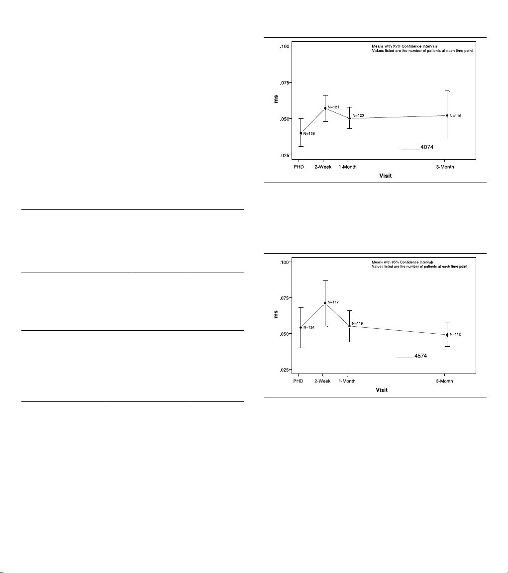
For Model 4074 pacing performance, the 95% upper confidence
bound on the difference between the two means was 0.011 ms,
which was below the 95% upper bound criteria of 0.06 ms.
Therefore, the objective concerning the equivalence of ventricular
pulse width thresholds was met (Figure 2).
Figure 2. Ventricular pulse width thresholds at 2.5 V
For Model 4574 pacing performance, the 95% upper confidence
bound on the difference between the two means was 0.008 ms,
which was below the 95% upper bound criteria of 0.06 ms.
Therefore, the objective concerning the equivalence of atrial
pulse width thresholds was met (Figure 3).
Figure 3. Atrial pulse width thresholds at 2.5 V
For Model 4074 sensing performance, the 95% upper confidence
bound on the difference between the two means was 0.997 mV,
which was below the 95% upper bound criteria of 3.0 mV.
Therefore, the objective concerning the equivalence of ventricular
R-wave amplitudes was met (Figure 4).
7
Page 8

Figure 4. Ventricular R-wave amplitude
4574
Figure 6. Ventricular pacing impedances
For Model 4574 sensing performance, the 95% upper confidence
bound on the difference between the two means was 0.003 mV,
which was below the 95% upper bound criteria of 1.5 mV.
Therefore, the objective concerning the equivalence of atrial
P-wave amplitudes was met (Figure 5).
Figure 5. Atrial P-wave amplitude
For Model 4074 lead impedance, the 95% upper confidence
bound on the difference between the two means was -59 Ω, which
was below the 95% upper bound criteria of 200 Ω. Therefore, the
objective concerning the equivalence of ventricular pacing
impedances was met (Figure 6).
For Model 4574 lead impedance, The 95% upper confidence
bound on the difference between the two means was -21 Ω, which
was below the 95% upper bound criteria of 200 Ω. Therefore, the
objective concerning the equivalence of atrial pacing impedances
was met (Figure 7).
Figure 7. Atrial pacing impedances
Secondary objective – Lead performance with Ventricular
Capture Management
●
Characterize the distribution of false negative increases in
ventricular output due to the Ventricular Capture
Management feature.
Results – In order to fully evaluate Ventricular Capture
Management (VCM), a patient needs to have a continuum of data
from each device interrogation. There were 122 patients with
Ventricular Capture Management data available to analyze. Of
those patients, six experienced at least one false negative in
ventricular output due to the Ventricular Capture Management
feature. The 1-sided lower confidence bound on the proportion of
patients who did not experience a false negative (116/122 =
95.1%) was 90.5%.
8
Page 9

9 Directions for use
1
Proper surgical procedures and sterile techniques are the
responsibility of the medical professional. The following
procedures are provided for information only. Some implant
techniques vary according to physician preference and the
patient’s anatomy or physical condition. Each physician must
apply the information in these instructions according to
professional medical training and experience.
9.1 Opening the package
Within the sterile field, open the sterile package and remove the
lead and accessories.
9.2 Using a stylet guide and stylets
Caution: To avoid lead tip distortion, keep the stylet fully inserted
into the lead during lead introduction and while advancing the
lead. Keeping the stylet fully inserted into the lead is especially
important while navigating through tortuous veins that may cause
the stylet to “back out” of the lead.
Caution: To avoid damage to the stylet, do not use a sharp object
to impart a curve to the distal end of a stylet (Figure 8).
The lead is packaged with the stylet guide attached to the
connector pin and a stylet already inserted into the lead. If the
stylet guide has been removed, replace it by gently pushing it as
far as possible onto the connector pin (Figure 9).
Figure 8.
9.3 Selecting an insertion site
Caution: When using a subclavian approach, insert the lead
using a more lateral approach to minimize the risk of first rib
clavicular crush. First rib clavicular crush may subsequently
fracture the lead body.
Caution: Certain anatomical abnormalities, such as thoracic
outlet syndrome, may pinch and subsequently fracture the lead
body.
The lead may be inserted by venotomy through several different
venous routes, including the right or left cephalic vein, other
subclavian branches, or the external or internal jugular vein. The
lead may also be inserted into a subclavian vein through a
percutaneous lead introducer (PLI). Select the desired entry site
(Figure 10).
Note: If wiping the lead is necessary before insertion, ensure that
the anchoring sleeve remains in position.
Figure 10.
1 Suggested entry site
9.4 Using the vein lifter
Use the stylet guide to insert a stylet into the lead. If a slight curve
is needed for the stylet, use only a smooth object to impart a curve
to the distal portion of a stylet (Figure 8).
Figure 9.
Caution: Use care when handling the lead during insertion. Avoid
placing the lead under extreme tension or angulation to prevent
possible lead fracture. Avoid gripping the lead with surgical
instruments.
Use the vein lifter:
1. Insert the tapered end of the vein lifter into the incised vein
(Figure 11).
Figure 11.
2. Gently push the lead tip underneath the vein lifter and into
the vein.
9.5 Positioning a tined ventricular lead
Warning: To minimize the occurrence of perforation and
dissection, avoid known infarcted or thin ventricular wall areas.
Positioning a tined ventricular lead:
9
Page 10

1. Advance the lead into the right atrium.
2. Use fluoroscopy to facilitate accurate lead placement.
3. Rotate and pass the lead through the tricuspid valve.
Rotating the lead or stylet eases passage of the lead as it is
advanced through the tricuspid valve or its chordae
tendineae.
Note: For added control in maneuvering the lead tip through
the tricuspid valve, curve the distal end of the lead slightly by
inserting a gently curved stylet. Refer to Section 9.2 for
instructions about imparting a curve to a stylet. The lead tip
may then be directly advanced through the valve, or it may
be projected against the lateral atrial wall with the curved
portion of the lead backed across the tricuspid valve.
4. If using a curved stylet, replace the curved stylet with a
straight stylet after the lead tip is passed into the right
ventricle.
5. Withdraw the stylet slightly or back the distal lead tip out of
the pulmonary outflow tract to avoid using excessive tip force
while achieving the final electrode position.
6. Use fluoroscopy (lateral position) to ensure that the tip is not
in a retrograde position or is not lodged in the coronary sinus.
Accurate positioning and wedging of the electrode is essential for
stable pacing and sensing. A satisfactory position is achieved
when the lead tip points straight toward the apex or when the distal
end dips or bends slightly (Figure 12).
Figure 12.
9.6 Taking electrical measurements
Take electrical measurements:
1. Attach the clip of a surgical cable to the notch on the stylet
guide (Figure 13).
Figure 13.
Note: A unipolar lead requires the use of an indifferent
electrode.
2. Use an implant support instrument to obtain electrical
measurements. Medtronic recommends using a pacing
system analyzer. For information on the use of the implant
support instrument, see the product literature for that device.
Satisfactory lead placement is indicated by low stimulation
thresholds and adequate sensing of intracardiac signal
amplitudes. Refer to Table 3 for recommended stimulation
threshold and sensing amplitude measurements at implant.
●
A low stimulation threshold provides for a desirable
safety margin, allowing for a possible rise in thresholds
that may occur within 2 months following implant.
●
Adequate sensing amplitudes ensure that the lead is
properly sensing intrinsic cardiac signals. Minimum
signal requirements depend on the device’s sensitivity
capabilities. Acceptable acute signal amplitudes for the
lead must be greater than the minimum device sensing
capabilities, including an adequate safety margin to
account for lead maturity.
Table 3. Recommended measurements at implant
Measurement required Ventricle Atrium
Maximum acute stimulation thresholds
Minimum acute sensing amplitudes 5.0 mV 2.0 mV
a
At pulse duration setting of 0.5 ms.
a
1.0 V
3.0 mA
1.5 V
4.5 mA
3. If electrical measurements do not stabilize to acceptable
levels, repositioning the lead and repeating the testing
procedure may be necessary.
Note: Initial electrical measurements may deviate from the
recommendations because of acute cellular trauma. If such
a deviation occurs, wait 5 to 15 minutes and repeat the
testing procedure. Values may vary depending upon lead
type, device settings, cardiac tissue condition, and drug
interactions.
9.6.1 Checking diaphragmatic stimulation for tined leads
Diaphragmatic stimulation should also be checked by pacing at
10 V and a pulse width setting greater than 0.5 ms and observing
for diaphragmatic contracting either by fluoroscopy or direct
abdominal palpitation. This should be checked for both atrial and
ventricular leads. Further testing may include patient positional
changes to simulate upright chronic conditions.
If diaphragmatic pacing occurs, reduce the voltage until a
diaphragmatic pacing threshold is determined. A diaphragmatic
threshold of 5 to 6 V or less usually necessitates repositioning of
the lead.
9.6.2 Taking pacing impedance (or resistance) measurements
Pacing impedance (or resistance) is used to assess device
function and lead integrity during routine device patient follow-up
sessions and to assist in troubleshooting suspected lead failures.
10
Page 11
Additional troubleshooting procedures include ECG analysis,
1
visual inspection, measurement of thresholds, and electrogram
characteristics.
Pacing impedance values are affected by many factors including
lead position, electrode size, conductor design and integrity,
insulation integrity, and the patient’s electrolyte balance.
Apparent pacing impedance is also significantly affected by the
measurement technique. Comparison of pacing impedance
should be done using consistent methods of measurements and
equipment.
An impedance higher or lower than the typical values is not
necessarily a conclusive indication of a lead failure. Other causes
must be considered as well. Before reaching a conclusive
diagnosis, the full clinical picture must be considered. The full
clinical picture includes pacing artifact size and morphology
changes in 12-lead analog ECGs, muscle stimulation with bipolar
leads, sensing and/or capture problems, patient symptoms, and
device characteristics.
Recommendations for clinically monitoring and evaluating leads
in terms of impedance characteristics are listed below.
Consider the following recommendations for devices with
telemetry readout of impedance:
●
Routinely monitor and record impedance values at implant
and follow-up sessions using consistent output settings.
Note: Impedance values may be different at different
programmable output settings (for example, pulse width or
pulse amplitude) of the device or pacing system analyzer.
●
Establish a baseline chronic impedance value once the
impedance has stabilized, generally within 6 to 12 months
after implant.
●
Monitor for significant impedance changes and abnormal
values.
●
Where impedance abnormalities occur, closely monitor the
patient for indications of pacing and sensing problems. The
output settings used for measuring impedance should be the
same as those used for the original measurements.
●
For patients at high risk, such as implantable
device-dependent patients, physicians may want to consider
further action such as increased frequency of monitoring,
provocative maneuvers, and ambulatory ECG monitoring.
Consider the following recommendations for devices without
telemetry:
●
Record the impedance value at implant. Also record the
measurement device, its output settings, and the procedure
used.
●
At the time of device replacement, if pacing system
analyzer-measured impedance is abnormal, carefully
evaluate lead integrity (including thresholds and physical
appearance) and patient condition before electing to reuse
the lead.
●
Impedances below 250 Ω may result in excessive battery
current drain, which may seriously compromise device
longevity, regardless of lead integrity.
For more information on obtaining electrical measurements,
consult the product literature supplied with the testing device.
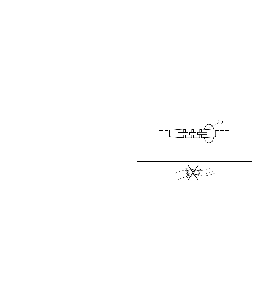
9.7 Anchoring the lead
Cautions:
●
Use care when anchoring the lead.
●
Use an anchoring sleeve with all leads.
●
Do not use absorbable sutures to anchor the lead.
●
Do not secure the sutures so tightly that they damage the vein,
lead, or anchoring sleeve.
●
Do not use the anchoring sleeve tabs for suturing (Figure 14).
●
Do not tie a suture directly to the lead body (Figure 15).
●
Do not dislodge the lead tip.
●
Do not attempt to remove or cut the anchoring sleeve.
●
Do not remove the tabs on anchoring sleeves. Tabs are
provided to minimize the possibility of the sleeve entering the
vein.
●
If using a large diameter percutaneous lead introducer (PLI)
sheath, extreme care should be taken to prevent passage of
the anchoring sleeve into the PLI lumen or the venous system.
Figure 14.
1 Anchoring sleeve tab
Figure 15.
With a triple groove anchoring sleeve, generally 2 or 3 of the
grooves may be used with the following procedure.
Anchor the lead:
1. Position the anchoring sleeve close to the lead’s connector
pin to prevent inadvertent passage of the sleeve into the vein.
2. Insert the anchoring sleeve partially into the vein.
3. Use the most distal suture groove to secure the anchoring
sleeve to the vein.
4. Use the middle groove to secure the anchoring sleeve to the
fascia and lead (Figure 16):
a. Create a base by looping a suture through the fascia
underneath the middle groove and tying a knot.
b. Firmly wrap the suture around the middle groove and tie
a second knot.
11
Page 12

Figure 16.
5. If anchoring with all 3 grooves, use the third and most
proximal groove to secure the anchoring sleeve to the lead
body (Figure 17).
Figure 17.
9.8 Connecting the lead
Caution: Always remove the stylet and stylet guide before
connecting the lead to the device. Failure to remove the stylet and
stylet guide may result in lead failure.
Connect the lead to the device:
1. Carefully and completely remove the stylet and stylet guide.
Note: When removing the stylet and stylet guide, firmly grip
the lead just below the connector pin to help prevent possible
lead dislodgement.
2. Obtain final electrical measurements.
3. Insert the lead connector into the connector block on the
device. For instructions on proper lead connections, see the
product documentation supplied with the device.
9.9 Placing the device and lead into the pocket
Cautions:
●
Use care when placing the device and lead into the pocket.
●
Ensure that the lead does not leave the device at an acute
angle.
●
Do not grip the lead or device with surgical instruments.
●
Do not coil the lead (Figure 18). Coiling the lead can twist the
lead body and may result in lead dislodgement.
Figure 18.
Caution: To prevent undesirable twisting of the lead body, wrap
the excess lead length loosely under the device and place both
the device and the lead into the subcutaneous pocket.
Place the device and lead into the pocket:
1. Rotate the device to loosely wrap the excess lead length
under the device (Figure 19).
Figure 19.
2. Insert the device and lead into the pocket.
3. Suture the pocket closed.
4. Monitor the patient’s electrocardiogram until the patient is
discharged. If a lead dislodges, it usually occurs during the
immediate postoperative period.
9.10 Post-implant evaluation
After implant, monitor the patient’s electrocardiogram until the
patient is discharged. If a lead dislodges, it usually occurs during
the immediate postoperative period.
Recommendations for verifying proper lead positioning include
x-rays and pacing/sensing thresholds taken at pre-hospital
discharge, 3 months after implant, and every 6 months thereafter.
In the event of a patient death, explant all implanted leads and
devices and return them to Medtronic with a completed Product
Information Report form. Call the appropriate phone number on
the back cover if there are any questions on product handling
procedures.
10 Specifications (nominal)
Parameter Model 4074
Type Bipolar
Chamber Ventricle
Fixation 4 tines, each 2.5 mm (0.098 in)
in length
Length 20-110 cm
Connector IS-1 BI
Material Conductor: MP35N nickel alloy
Connector pin: Stainless steel
Connector ring: Stainless steel
Inner insulator: Silicone
Outer insulator: Polyurethane
Ring electrode: Titanium nitride coated platinum
alloy
Tip electrode: Titanium nitride coated platinum
alloy
12
Page 13

Parameter Model 4074
Tines: Polyurethane
Tip electrode configuration Ring-shaped, porous, titanium
nitride coated, steroid-eluting
Diameters Lead body: 1.8 mm (0.071 in)
Ring electrode: 1.9 mm (0.075 in)
Tip electrode: 1.6 mm (0.063 in)
Lead introducer (recommended size)
without guide wire: 2.3 mm (7 French)
with guide wire: 3.0 mm (9 French)
Electrode
Ring: 24 mm
2
surface area
Tip: 2.5 mm
2
Resistance Unipolar: 41 Ω (58 cm)
Bipolar: 83 Ω (58 cm)
Tip to ring
17 mm (0.67 in)
spacing
Steroid Dexamethasone acetate
Amount of steroid 272 µg (target dosage)
Steroid binder Silicone
Figure 20.
1 Lead length: 20-110 cm
2 Tip electrode; surface area: 2.5 mm
3 Tip to ring spacing: 17 mm (0.67 in)
4 Ring electrode; surface area: 24 mm
5 Insulation material: polyurethane
6 Connector: IS-1 BI
2
2
13
Page 14

11 Medtronic warranty
For complete warranty information, see the accompanying
warranty document.
12 Service
Medtronic employs highly trained representatives and engineers
located throughout the world to serve you and, upon request, to
provide training to qualified hospital personnel in the use of
Medtronic products. Medtronic also maintains a professional staff
to provide technical consultation to product users. For more
information, contact your local Medtronic representative, or call
or write Medtronic at the appropriate telephone number or
address listed on the back cover.
14
Page 15

Page 16

World Headquarters
*M954531A001*
Medtronic, Inc.
710 Medtronic Parkway
Minneapolis, MN 55432
USA
www.medtronic.com
Tel. +1 763 514 4000
Fax +1 763 514 4879
Medtronic USA, Inc.
Toll-free in the USA (24-hour technical consultation for
physicians and medical professionals)
Bradycardia: +1 800 505 4636
Tachycardia: +1 800 723 4636
Europe/Africa/Middle East Headquarters
Medtronic International Trading Sàrl
Route du Molliau 31
Case Postale 84
CH-1131 Tolochenaz
Switzerland
www.medtronic.com
Tel. +41 21 802 7000
Fax +41 21 802 7900
Medtronic E.C. Authorized Representative
Medtronic B.V.
Earl Bakkenstraat 10
6422 PJ Heerlen
The Netherlands
Tel. +31 45 566 8000
Fax +31 45 566 8668
Technical manuals:
www.medtronic.com/manuals
© Medtronic, Inc. 2013
M954531A001A
2013-02-20
 Loading...