

Page 1

AEX
Operator’s Manual
40-405-1
™
Generator
Page 2

Page 3

AEX
Operator’s Manual
40-405-1
™
Generator
Page 4

Copyright and
Only
Trademarks
© 2016, 2017 Medtronic. All rights reserved. Medtronic, Medtronic logo and Further, Together
are trademarks of Medtronic. ™* Third party brands are trademarks of their respective owners.
All other brands are trademarks of a Medtronic company.
No part of this publication may be reproduced, transmitted, transcribed, stored in retrieval
systems, or translated into any form, or by any means: electronic, mechanical, magnetic,
optical, or otherwise, without the prior written permission of Medtronic Advanced Energy,
LLC, 180 International Drive, Portsmouth, NH 03801, United States of America.
Disclaimer
Medtronic reserves the right to change its products and services at any time to incorporate
the latest technological developments. This guide is subject to change without notice.
◆ CAUTION: Federal (USA) law restricts this device to sale by or on the order of
a physician.
Customer Service Telephone Numbers:
U.S.:
Tel: +18667779400
Fax: +18662220900
UnitedKingdom:
Tel: +441923212213
Fax: +441923241004
China:
Tel: +862150800998
Fax: +862150800978/50801850
Germany:
Tel: +492115293209
Fax: +492115293302
France:
Tel: +33470679800
Fax: +33470679820
Belgium-Luxemburg:
Tel: +3224560900
Fax: +3224602667
Canada:
Tel: +18002685346
Fax: +19058266620
India:
Tel: +912226836733
Fax: +912226830806
Japan:
Tel: +8136430.2011
Fax: +81364307110
Netherlands:
Tel: +31455668000
Fax: +31455668042
Page 5

Contents
1. Preface
About This Manual ................................................................................................................................................................................. 1-1
Conventions Used in This Manual ........................................................................................................................................... 1-1
Help .................................................................................................................................................................................................... 1-1
Indications ................................................................................................................................................................................................ 1-1
Contraindications .................................................................................................................................................................................. 1-2
Warnings and Cautions ........................................................................................................................................................................1-2
2. Introduction
AEX™ Generator ...................................................................................................................................................................................... 2-1
Electrosurgical Modes .......................................................................................................................................................................... 2-2
Controls, Displays, and Receptacles .......................................................................................................................................2-3
3. Installation
Initial Inspection ..................................................................................................................................................................................... 3-1
Installation ................................................................................................................................................................................................ 3-1
Optional Wireless Footswitch ............................................................................................................................................................ 3-2
Preliminary Checks ................................................................................................................................................................................ 3-2
Preliminary Functional Testing ..........................................................................................................................................................3-2
4. Operation .................................................................................................................................................................................................. 4-1
Using the Touch Screen ....................................................................................................................................................................... 4-1
Turn on Generator ................................................................................................................................................................................. 4-2
Connect the Patient Return Electrode to Patient and Generator ......................................................................................... 4-3
Plugging in the Handpiece to the AEX™ Generator ................................................................................................................. 4-4
Loading the Pump Segment Portion of the Handpiece into the Pump Head of the AEX™ Generator ................... 4-5
Adjusting RF Power Levels .................................................................................................................................................................. 4-8
Adjusting the Saline Flow Rate ......................................................................................................................................................... 4-9
Activating the Handpiece ................................................................................................................................................................... 4-9
Using an Optional Footswitch ........................................................................................................................................................... 4-9
Adjusting RF Power Settings Using Memory Buttons ............................................................................................................4-10
Adjusting the Volume of the Activation Tone ............................................................................................................................4-10
After Surgery .........................................................................................................................................................................................4-11
Disposing of the Handpiece ...................................................................................................................................................4-11
Preparing the AEX™ Generator for Reuse ..........................................................................................................................4-11
Transportation and Storage of the AEX™ Generator .....................................................................................................4-12
5. Cleaning and Maintenance
Inspections Required Before Each Use ........................................................................................................................................... 5-1
Required Annual Inspections ............................................................................................................................................................ 5-1
Cleaning .................................................................................................................................................................................................... 5-1
Maintenance ............................................................................................................................................................................................ 5-2
Service ........................................................................................................................................................................................................ 5-2
Storage ....................................................................................................................................................................................................... 5-2
Environmental Protection ...................................................................................................................................................................5-2
6. Troubleshooting
Monopolar and Bipolar Errors ........................................................................................................................................................... 6-1
Error Code Details .................................................................................................................................................................................. 6-2
Monopolar and Bipolar Faults ........................................................................................................................................................... 6-5
AEX™ Generator Operator’s Manual i
Page 6

Fault Code Details .................................................................................................................................................................................. 6-6
Error Codes and Error Handling ........................................................................................................................................................ 6-9
Troubleshooting Malfunctions .......................................................................................................................................................6-10
7. Specications
AEX™ Generator ...................................................................................................................................................................................... 7-1
Output Characteristic Curves ............................................................................................................................................................ 7-7
8. Limited Express Warranty and Disclaimers .............................................................................................................................. 8-1
Limited Express Warranty.................................................................................................................................................................... 8-1
9. Product Accessories ............................................................................................................................................................................. 9-1
10. Glossary ...................................................................................................................................................................................................10-1
11. Symbols ....................................................................................................................................................................................................11-1
List of Tables
Table 6-1 Error Codes ................................................................................................................................................................... 6-1
Table 6-2 Fault Codes...................................................................................................................................................................6-5
Table 6-3 Troubleshooting.......................................................................................................................................................6-10
Table 7-1 Mains Input Characteristics .................................................................................................................................... 7-2
Table 7-2 Output Characteristics ............................................................................................................................................. 7-3
Table 7-3 Attached Accessory Cables .................................................................................................................................... 7-4
Table 7-4 Electromagnetic Emissions .................................................................................................................................... 7-4
Table 7-5 Electromagnetic Immunity .................................................................................................................................... 7-5
Table 11-1 Symbols .......................................................................................................................................................................11-1
ii
Page 7

1. Preface
About This Manual
The AEX™ Generator Operator’s Manual provides detailed information on operating and maintaining the AEX™
Generator. This manual and the equipment described within are for use only by qualied medical personnel
possessing training in the surgical procedures to be performed.
For information on accessories, refer to the appropriate Instructions For Use. The AEX™ Generator is
compatible with all Aquamantys™ and PlasmaBlade™ single use only accessories.
Conventions Used in This Manual
▲ WARNING: A warning indicates a hazardous condition that may result in injury or death, if not
corrected or avoided.
◆ CAUTION: Alerts you to the possibility of a problem with the device associated with its use or misuse
resulting in equipment damage or failure in a procedure, if not corrected or avoided.
■ IMPORTANT: Highlights important information for a particular section.
● NOTE: Points out additional information that may be helpful.
Help
Read through the section of the guide specic to the procedure you are performing. Refer to the table of
contents and index to locate information. A glossary is included to assist you with any unfamiliar terms.
1. See Troubleshooting on page6-1 for a list of problems and suggested solutions.
2. For technical support, contact +1 866 777 9400.
Indications
The AEX™ Generator is a radio frequency (RF) electrosurgical generator capable of simultaneously powering
specied monopolar and bipolar electrosurgical instruments. It is intended to be used for delivery of RF energy
to instruments indicated for cutting and coagulation of soft tissue and for delivery of RF energy concurrent
with saline to instruments indicated for hemostatic sealing and coagulation of soft tissue and bone. It is
intended for, but not limited to, General, Plastic and Reconstructive (including but not limited to skin incisions
and development of skin aps), ENT, Gynecologic, Orthopaedic, Arthroscopic, Spinal and Neurological,
Thoracic, and Open abdominal surgery procedures. The device is not intended for contraceptive tubal
coagulation (permanent female sterilization).
AEX™ Generator Operator’s Manual 1-1
Page 8

Contraindications
The AEX™ Generator with Aquamantys™, Transcollation™ and PlasmaBlade™ should not be used on small
appendages or body parts, as in nger surgery or circumcision.
Warnings and Cautions
Electrosurgery has been used safely in many procedures. Physicians should be familiar with the medical
literature, complications, and hazards associated with electrosurgery before beginning any electrosurgical
procedure. Electrosurgery, if misused, can pose dangers to patients or sta, as well as other equipment. Safe
and eective electrosurgery is dependent not only on equipment design, but also on factors under the control
of the user, such as surgical training and clinical decision making. The warnings and cautions presented in this
manual should be read, understood and followed for safety purposes.
▲ Warnings for Equipment Preparation
• Connect the Generator electrical cord to a properly grounded Hospital Grade receptacle. Do not use extension
cords or three-prong to two-prong adapters with the Generator. Improper grounding may result in equipment
damage, re at the receptacle, or injury to the patient or user.
NOTE: “Use Hospital Grade receptacle for grounding reliability” statement applies to US/North America power
cords only.
• To allow for appropriate cooling, the unit should not be installed in a cabinet or similar enclosure. If mounted
on a shelf, or near a wall, allow a three-inch clearance around the unit to permit free circulation of air on all
sides of the unit. Appropriate cooling is necessary to avoid overheating of the unit.
• Do not stack equipment on top of the AEX™ Generator or place the generator on top of electrical equipment.
This may block access to the unit and not allow for proper ventilation.
• Provide as much distance as possible between the AEX™ Generator and other electronic equipment (such as
monitors). An activated electrosurgical generator may cause interference with them.
• Prior to use, inspect the AEX™ Generator and its accessories for any obvious defects or improper connections.
Do not use the Generator if it appears to be damaged, as product failure or injury may occur.
• Avoid uid contact with the accessory cable interfaces to the AEX™ Generator receptacles, because shorting
can occur which can damage the accessory connectors and/or the AEX™ Generator receptacles.
• Use only AEX™ Compatible Footswitches.
• Do not use cords as handles as insulation damage could occur and increase the risk of burns or cause other injury.
• Do not wrap power cords around metal objects. This may induce currents that could lead to shock, re, or
injury to the patient or surgical team. All power cords should be positioned in a way to avoid contact with the
patient or other cables.
• Nonfunction of the AEX™ Generator may cause interruption of surgery. A backup generator or alternative
surgical techniques should always be available.
• Interference from high frequency surgical equipment may adversely aect the operation of other electronic medical equipment in the operating room. Interference may be resolved or reduced by rearranging the
Generator’s cables such that they do not overlap the cables from other equipment, or by using dierent power
outlets or extension cords for the dierent pieces of equipment.
• Patient monitoring systems that incorporate high-frequency current-limiting devices are recommended for
use in an electrosurgical site.
1-2 Preface
Page 9

▲ Warnings for Accessories
• Prior to use, inspect all accessory devices, handpieces, and the AEX™ Generator for defects. Do not use if
insulation or connectors are damaged, because product failure or injury may occur.
• The AEX™ Generator is compatible with all Aquamantys™ and PlasmaBlade™ handpieces.
• The AEX™ Generator is not compatible with Aquamantys™3 handpieces.
• Do not reuse, resterilize or reprocess “Single Use Only” labeled accessory devices, because product failure or
injury may occur.
• The handpieces and Patient Return Electrodes have appropriate connectors and receptacles. Do not attempt
to connect to the improper receptacle because connector damage can occur, which may result in a failure.
Ensure all connections are secure before activating the system.
• Verify that the Patient Return Electrode is properly applied to the patient and the cable is securely connected
to the Patient Return Electrode receptacle. If there is an improper connection the AEX™ Generator may not
operate as intended.
• Do not connect wet connectors to the AEX™ Generator as this may result in equipment damage, re at the
receptacle, or injury to the patient or user.
• Do not wrap cords around metal objects as this may induce currents that could produce system performance
changes, shocks, res, or injury to the patient or surgical personnel.
• Do not use accessories other than the ones recommended in Product Accessories. Use of other accessories
may result in an unintended output and/or injury to patient.
• Use active accessories with rated voltage equal to or greater than that of the AEX™ Generator’s maximum
output voltage.
▲ Warnings for Patient Preparation
• Observe re precautions at all times. An electrosurgical device may provide an ignition source due to sparking
and heating.
• Do not use in the presence of ammable anesthetics or oxidizing gases such as nitrous oxide and oxygen.
Do not activate the unit until vapors from alcohol-based skin prepping agents have dissipated. Naturally
occurring gases that accumulate in body cavities can also be an ignition source.
• Ensure that all oxygen circuit connections and endotracheal tubes are leak-free before and during
electrosurgery use. An oxygen leak could result in an airway re.
• Inadvertent patient contact may result in burns. When not in use, place all accessory devices in a dry and
nonconductive area away from the patient.
• Position the cables for a Monopolar handpiece and the Patient Return Electrode to avoid patient contact
to protect against high frequency current paths to the patient, as such contact may result in patient or user
injury.
• Do not allow patient contact with grounded metal objects or objects that have an appreciable capacitance
to earth (e.g., operating table supports), as such contact may result in patient or user injury.
• Skin-to-skin contact (e.g., between the arms and body of the patient) should be avoided, e.g., by insertion of
dry gauze.
AEX™ Generator Operator’s Manual 1-3
Page 10

• Monopolar devices require a Patient Return Electrode. The Generator must detect proper Patient Return
Electrode impedance before output can be active. The impedance is continuously monitored and displayed
while in Monopolar Mode. The Generator presents audible and visible alarms if it detects improper impedance
with the Patient Return Electrode in Monopolar Mode and will disable Generator output. Unless a compatible
split foil Patient Return Electrode is used, loss of safe contact between the return electrode and the patient
will not result in an audible and visible alarm, and the Generator output will not be disabled. The entire area
of the Patient Return Electrode should be reliably attached to a suitably prepared and appropriate area of the
patient’s body as dened by the manufacturer. Refer to the manufacturer’s instructions for application site
and placement procedures when applying the Patient Return Electrode. Do not rely entirely on the impedance
sensing feature. It can be aected by a damaged (shorted) Patient Return Electrode. It is recommended that
the operator verify appropriate placement and contact of the Patient Return Electrode. Inadequate contact of
the Patient Return Electrode may result in patient alternate site burns or injury.
• Do not cut a Patient Return Electrode to reduce size as this could result in high current density patient burns.
• Heat applied by thermal blankets or other sources may be cumulative with heat from the Patient Return
Electrode (caused by electrosurgical currents). Choose a Patient Return Electrode site remote from other heat
sources to help minimize the risk of patient injury.
• Electrodes and probes used with monitoring, stimulating, and imaging devices can provide paths for high
frequency currents even if the electrodes or probes are insulated, battery operated, and/or isolated at
50/60 Hz. To reduce the risk of burns, place any such electrode or probe as far away as possible from the
electrosurgical site and the Patient Return Electrode.
• Needle monitoring electrodes are not recommended as burns may inadvertently result.
• The active device should not be used near electrocardiograph electrodes as it may cause interference.
• Physiological monitoring devices and their monitoring electrodes should be positioned away from the surgical
site where the AEX™ System will be utilized.
• Always use the lowest RF power setting to achieve the desired surgical eect. Pediatric applications and/
or procedures performed on small anatomic structures may require reduced power settings. The higher the
power and the longer the power is applied, the greater the possibility of unintended thermal damage to tissue.
• Adequate ventilation to reduce electrosurgical smoke by use of a smoke-plume evacuator or other means is
recommended.
• Do not attempt to alter device congurations or replace device components with nonstandard parts since this
may result in decreased device performance, device malfunction, or patient injury.
• Transcollation delivers RF energy in conjunction with saline. Do not inhibit the delivery of saline as burns may
inadvertently result.
▲ Warnings for Active Implants
• If the patient has an internal cardiac debrillator (ICD), contact the ICD manufacturer for instructions before
performing an electrosurgical procedure. Electrosurgery may cause multiple activations of ICDs.
• Use the AEX™ System with caution in the presence of pacemakers or other active implants, as electrosurgical
equipment may cause interference with these devices or cause them to malfunction. Consult the active
implant manufacturer for further information before proceeding with the surgery.
• The use of electrosurgery in the presence of internal or external active implants is potentially hazardous.
• To minimize the possibility of active implant interference, place the Patient Return Electrode such that the
electrosurgical current path is as far as possible from the active implant lead.
• Direct contact with implanted leads can cause physical damage to the leads. Exercise caution around leads
associated with any active implant; particularly those with thin insulation.
1-4 Preface
Page 11

▲ Warnings for Use
• It is recommended that physicians utilize pre-clinical training, review of pertinent literature, and other
appropriate educational tools before attempting newer surgical procedures, such as endoscopic, laparoscopic,
or thoracoscopic procedures.
• Read the warnings, precautions, and instructions provided with AEX™ disposable handpieces before using.
Specic instructions are not included in this manual.
• If using the optional footswitch, ensure that the footswitch is not inadvertently depressed to prevent the
device from being unintentionally activated. Place the footswitch in a location necessitating deliberate action
in order to activate the unit.
• If using the optional footswitch, only the primary surgeon using the handpiece should operate the footswitch.
Unintentional activation may occur if the footswitch is activated by a separate user, which may result in patient
or user injury.
• Ensure that the sound volume on the Generator is adequately adjusted so that the activation tones are clearly
heard. The activation tones are intended to alert the user that the device is active. This will help prevent
unintended contact with the device which could result in patient or user injury.
• Examine the handpiece before connecting it to the AEX™ Generator. After connecting the handpiece, ensure
that the handpiece and the unit are functioning as intended.
• Consult the operating and user manuals for light sources and other ancillary devices for warnings, precautions,
and instructions prior to their use with the AEX™ Generator.
• Position the AEX™ Generator away from life supporting and/or monitoring systems to reduce/avoid
interference with these systems.
• The interference produced by the operation of RF surgical equipment may adversely inuence the operation
of other electronic equipment.
• DO NOT use electrosurgery in the presence of ammable anesthetics or other ammable gases, near
ammable uids or objects, or in the presence of oxidizing agents as re could result.
• The cable on the disposable handpieces should be positioned in a way to avoid contact with the patient or
other cables.
• Monitoring systems incorporating RF current limiting devices are recommended.
• For surgical procedures where the RF current could ow through parts of the body having a relatively small
cross sectional area, the use of bipolar techniques may be desirable in order to avoid unwanted tissue damage.
• During use, a diminished power output may indicate that the Patient Return Electrode connection has been
compromised, failure of an electrical lead, active electrode insulation failure or excessive eschar buildup on
the active electrode tip. Do not increase the power output before checking for obvious defects or improper
connections. Check for eective contact of the Patient Return Electrode to the patient any time that the
patient is moved after initial application of the Patient Return Electrode.
• If the system resets due to a power interruption or low voltage, the system will check for eective contact of
the Patient Return Electrode, however the user should verify eective contact of the Patient Return Electrode
visually prior to resuming electrosurgery.
• If power levels were increased to compensate diminished performance, it is recommended to reduce power to
the original or a lower level upon resumption of use.
• The output power selected should be as low as possible for the intended purpose.
• Failure of the high-frequency surgical equipment could result in an unintended increase of output power.
AEX™ Generator Operator’s Manual 1-5
Page 12

• Do not use Monopolar electrosurgery on small appendages, such as in nger surgery, as it can cause thrombosis or other unintended injury to tissue proximal to the surgical site.
• Studies have shown that smoke generated during electrosurgery may be harmful to surgical personnel. These
studies recommend the use of a surgical mask and adequate ventilation of the smoke using a surgical smoke
evacuator or other means.
• Neuromuscular stimulation can occur causing unexpected patient movement, especially with modes producing electrical arcs between the active device electrode and tissue. Use caution in proximity to neural
structures.
• Observe all caution and warning notices printed on the unit.
• Operating room sta should never contact the handpiece tip while the Generator is active, as injury may result.
• The tip of a recently activated handpiece may be hot enough to cause patient burns or ignite surgical drapes
or other ammable material. When not in use, store the device in an electrically insulated container or holster.
Never place or rest a handpiece on the patient.
▲ Warnings for Testing or Servicing
• Do not remove the Generator cover due to electrical shock hazard. There are no user serviceable parts inside.
• Never remove or install any parts with power ON, as this may result in potential for electrical shock or injury.
Use only Medtronic Advanced Energy approved replacement parts in order to avoid potential equipment
damage or injury.
• Avoid contact with the output leads when the Generator is activated as this may result in injury. Periodically
inspect the test leads used for the output connections for obvious defects.
• The Generator is not designed to operate for extended periods of continuous output. When testing, it is
recommended that duty cycles be limited to 25% with maximum activation times of 10 seconds into a
load greater than or equal to 600 ohms. Use for an extended period of time may result in overheating and
equipment damage.
• Periodic maintenance should be performed by a hospital qualied biomedical technician or by a qualied
Medtronic representative.
• Minimizing operating temperature and extreme thermal cycles will extend the equipment life.
• The heat dissipation capability of the Generator heat sink may be severely impaired by activating the AEX™
Generator in other than a normal operating position. Testing or using the unit in any other position should
be avoided.
1-6 Preface
Page 13
2. Introduction
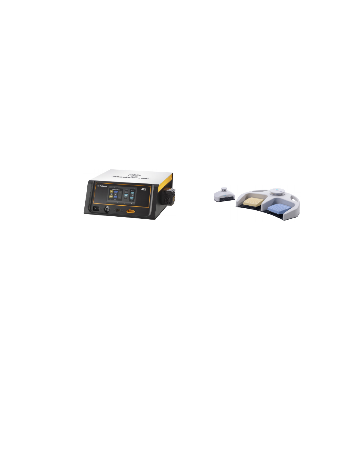
AEX™ Generator
The AEX™ Generator is one component of the AEX™ Surgery System. The Generator provides radio frequency
(RF) energy to disposable Monopolar and Bipolar electrosurgical handpieces. The AEX™ Generator accepts a
Patient Return Electrode for monopolar applications, and includes a rotary peristaltic pump for simultaneous
delivery of saline for a hemostatic sealing.
Figure 2-1. AEX™ Generator and AEX™ Wireless Footswitch
AEX™ Generator
AEX™ Wireless Footswitch
RF Power
The AEX™ Generator delivers Bipolar RF power and saline with power settings in 5 watt increments in the
range of 20 to 100 Watts and 10 Watt increments in the range of 100 to 220 Watts. The AEX™ Generator
delivers Monopolar Cut, Coag, and Transcollation RF energy with a power output capable of up to 90 Watts.
All PlasmaBlade™ handpieces powered by the PlasmaBlade™ port contain an embedded chip dictating the
settings for that particular handpiece. Aquamantys™ handpieces do not have embedded chips. These settings
are described in the Instructions For Use accompanying the handpiece.
Simultaneous RF Power and Saline Delivery
The AEX™ Generator simultaneously delivers RF power and saline to Bipolar Handpieces and certain
Monopolar Handpieces when they are properly connected to the unit and the activation button on the
handpiece is depressed. For a list of all compatible simultaneous handpieces, please contact Medtronic
Advanced Energy Customer Service at +1 866 777 9400.
Saline Flow Rate Setting
The saline ow rate setting is determined based on the power setting and the selection of one of three
possible ow rate settings: Low, Medium, and High. The three possible saline ow rates for each power setting
are preset automatically in order to provide the optimal saline ow for a given power setting.
AEX™ Generator Operator’s Manual 2-1
Page 14

Priming
The AEX™ Generator has a convenient one touch priming function which automatically primes the
Transcollation handpiece with saline prior to use after the device has been correctly connected to the unit.
This function is activated by pressing the “PRIME” button on the unit.
Electrosurgical Modes
The AEX™ Generator operates in the following modes:
Cut Modes (Monopolar)
• Low Cut (Peak Cut) – Precision cutting with minimal hemostasis and minimal collateral damage
• Medium Cut (Pure Cut) – Precision cutting with increased hemostasis and collateral damage
• High Cut (Blend Mode) – Precision cutting with strong hemostasis
Coagulation Modes (Monopolar)
• Coagulation increases with higher settings.
• Low Coag (Pinpoint)
• High Coag (Spray)
Hemostatic Sealing Modes (Monopolar or Bipolar)
• Simultaneous delivery of RF energy with saline for hemostatic sealing of soft tissue and bone.
■ IMPORTANT:
• Each cut, coagulation, and seal mode has multiple power settings available.
• Handpiece models vary and may not utilize all modes. Available modes for each handpiece are per applicable
handpiece Instructions For Use.
Other features of the AEX™ Generator include:
• Proprietary handpieces developed by Medtronic Advanced Energy to deliver RF energy to the patient. Only
Medtronic Advanced Energy handpieces may be used with the AEX™ Generator.
• Handpiece control
• Handpiece with footswitch control
• Simultaneous activation of 2 handpieces
• Device default settings recognition
• Monopolar and Bipolar outputs
• Connection to Patient Return Electrode
• Color LCD to prompt user for input and to display informational, error, and fault messages
• Audio feedback of activation and alarm tones
2-2 Introduction
Page 15

Controls, Displays, and Receptacles
This section describes each component of the AEX™ Generator and its function. The controls, displays, and
receptacles for Monopolar and Bipolar handpieces, Patient Return Electrodes, and the footswitch are located
on the front and rear panels of the Generator.
▲ WARNING: Read all warnings and instructions provided with the Generator prior to use.
Front Panel Layout Description
Refer to Figure 2-2 for a complete front panel illustration. Each display, control, or receptacle is described in
more detail below.
Figure 2-2. Front Panel Layout
6. Touch Screen Display
1. Power Switch
Combo Receptacle
3. Patient Return
Electrode Receptacle
with Illumination of
Connection Status
4. Aquamantys™ Receptacle2. PlasmaBlade™ and
5. Rotary Peristaltic
Pump
1. Power Switch – A black rocker switch that toggles right to turn the AEX™ Generator
power on and toggles left to turn the power o.
2. PlasmaBlade™ and Combo Receptacle – A seven-pin circular receptacle that accepts
PlasmaBlade™ and Combo handpieces.
3. Patient Return Electrode Receptacle – A standard two-pin receptacle that accepts the
Patient Return Electrode connector used in Monopolar procedures.
AEX™ Generator Operator’s Manual 2-3
Page 16

4. Aquamantys™ Receptacle – A three-pin rectangular receptacle that accepts
Aquamantys™ handpieces.
5. Saline Pump – This is a rotary peristaltic pump. A special pump segment is attached
to the saline delivery tubing of each disposable handpiece which is designed to operate
with the pump. The pump segment is loaded into this pump head prior to operation of
the device.
6. Touch Screen Display – Screen used to prompt the user for input and to display
informational and fault messages to user.
Panel Layout Description
Refer to Figure 2-3 for a complete back panel illustration. Each control, receptacle, or panel is described in
more detail below.
Figure 2-3. Back Panel Layout
1. RS-232 Port
7. Name Plate
2. USB Port
3. Footswitch
Connector
4. Fuse Drawer
5. AC Mains Input
6. Equipotential
Ground Connector
1. RS-232 Port – Service port for use by trained personnel only.
2. USB Port – Enables uploading of software and downloading of usage data.
2-4 Introduction
3. Footswitch Connector – A connector that accepts an AEX™ Wireless Footswitch
connector.
4. Fuse Drawer – This fuse drawer contains two fuses.
Page 17

5. Power Entry / AC Mains – The power entry module combines the connector for the
3-prong, Hospital-Grade power cord with removable enclosure holding two line fuses.
Always use fuses of the rating shown in “Mains Input Characteristics” on page 7-2 of this
manual.
●NOTE: “Use Hospital Grade receptacle for grounding reliability” statement applies
to US/North America power cords only.
6. Equipotential Ground Connector – Standard connector for connecting common
grounds.
7. Name Plate – This plate species the model number, serial number, nominal line
voltages, frequency, current, and fuse rating information for the AEX™ Generator.
AEX™ Generator Operator’s Manual 2-5
Page 18

This page intentionally left blank.
2-6 Introduction
Page 19

3. Installation
Initial Inspection
Unpack the Generator upon receipt and physically inspect it for any obvious damage that may have occurred
during shipment. A qualied biomedical engineer or personnel familiar with electrosurgical devices should
perform this inspection.
If the Generator is damaged, call +1 866 777 9400 for assistance.
Installation
The AEX™ Generator should be placed on a at and stable surface.
▲ WARNING: The Hospital Grade power cord of the Generator should be connected to a properly polarized
and grounded power source whose voltage and frequency characteristics are compatible with those listed
on the nameplate of the AEX™ Generator (located on the rear panel of the Generator). Improper grounding
may result in equipment damage, re at the receptacle, or injury to the patient or user.
To completely disconnect the Generator from the AC mains, the power cord needs to be unplugged from
the power source. Do not position generator such that removal of the power cord from the power source
would be dicult.
● NOTE: “Use Hospital Grade receptacle for grounding reliability” statement applies to US/North America
power cords only.
▲ WARNING: To allow for appropriate cooling, do not install the Generator in a cabinet or similar enclosure.
If mounted on a shelf or near a wall, allow a 3-inch clearance around the Generator to permit free air
circulation on all sides. Appropriate cooling is necessary to avoid overheating of the Generator.
AEX™ Generator Operator’s Manual 3-1
Page 20

Optional Wireless Footswitch
● NOTE: The optional wireless footswitch is only compatible with enabled monopolar handpieces.
Monopolar activation may be initiated either from a footswitch or a handpiece. Transcollation function
cannot be activated by the footswitch.
1. If using the optional footswitch, plug the wireless receiver into the footswitch connector of the AEX™
Generator (see Figure 2-3 on page 2-4).
2. Turn on the AEX™ Generator and ensure that the wireless receiver’s power-on LED is green, indicating that
the receiver is powered on.
Figure 3-1. Wireless Receiver
Power-On
LED Indicator
▲ WARNING: Only the primary surgeon using the handpiece should operate the footswitch. Unintentional
activation may occur if the footswitch is activated by a separate user, which may result in patient or user injury.
Refer to the Wireless Footswitch Operator’s Manual for detailed product information.
Preliminary Checks
Prior to installing and using the Generator, it is strongly recommended that a qualied maintenance technician
ensure proper and safe operation by testing the performance of the Generator. If anomalous behavior is
observed, the Generator should not be used until all issues have been resolved by a qualied technician. Call
Medtronic Advanced Energy Customer Service at +1 866 777 9400.
Preliminary Functional Testing
Preliminary functional testing should be conducted by a qualied technician or operating room personnel.
Personnel conducting functional tests should read this manual prior to testing.
1. Turn on the Generator by pressing the power switch.
2. Verify the following occurs:
• A self-test screen appears indicating that the system is performing a power-on self-test as shown in
Figure 3-2. The software version is also shown at the bottom of the screen. If the self-test screen does
not appear, cycle the power and try again. If the same problem continues, call Medtronic Advanced
Energy Customer Service at +1 866 777 9400. Do not attempt to use the Generator until the problem
has been resolved.
3-2 Installation
Page 21

Figure 3-2. Front Panel Showing Self-Test Screen.
• The Cut and Coag activation tones will sound to allow you to verify operation.
• The screen in Figure 3-2 will disappear when the self-test is complete. If the self-test is not successful, an alarm
tone will sound, a Fault Code will be displayed on the LCD screen and the Generator output will be disabled.
The alarm tone will sound until the Generator is turned o. In this case, call Medtronic Advanced Energy
Customer Service. Do not attempt to use the Generator until the problem has been resolved.
• If the self-test is successful, verify the following:
• If the Generator is powered on with no handpieces connected, the Generator displays the following operational
screen.
Figure 3-3. Front Panel Showing Operational Screen with No Devices Connected.
Figure 3-4. Front Panel Displaying the Screen with PlasmaBlade™ Handpiece Connected.
AEX™ Generator Operator’s Manual 3-3
Page 22

Figure 3-5. Front Panel Displaying the Screen with Bipolar Handpiece Connected.
Figure 3-6. Front Panel Displaying the Screen with PlasmaBlade™ and Bipolar Handpieces Connected.
Figure 3-7. Front Panel Displaying the Screen with Combo Handpiece Connected.
Figure 3-8. Front Panel Displaying the Screen with PlasmaBlade™ and Bipolar Handpieces Connected and activated.
3-4 Installation
Page 23

4. Operation
Using the Touch Screen
The following are some typical examples of the touch screens and how to interact with them:
Sound Volume Control
Slide the control to the right to
increase the volume, slide the
control to the left to decrease
the volume.
Power Levels
Increase by pressing up arrow,
decrease by pressing down
arrow.
Figure 4-1. Touch screen
Footpedal Indicator
It is illuminated if a footswitch is
connected.
Saline Flow Rate Indicators
Press one of the three
indicators.
Figure 4-2. Numeric keyboard
Memory Buttons
They can be renamed by pressing and
holding the button for 1 second. Then a
keyboard will appear. Alpha and numeric
keyboards are available (see Figures 4-2 &
4-3). In order to preset the memory button
with power level preferences, the handpieces
need to be plugged in to the AEX™ Generator
display. Then change the handpiece power
levels. Once the power levels have been
changed, press and hold the memory button
to save the preferences.
Figure 4-3. Alpha keyboard
AEX™ Generator Operator’s Manual 4-1
Page 24

Turn on Generator
1. Ensure the power switch is o, and then connect the power cord to a properly grounded and polarized
mating power receptacle.
2. Set the power switch to the ON position. The color LCD on the front panel will illuminate and show a selftest screen (Figure 4-4). The self-test will take approximately 10 seconds to complete.
Figure 4-4. Self test.
After the Generator goes through its internal self-diagnostics, the Generator should respond by:
• The self-test screen will be replaced with an operational screen (Figure 4-5), and the generator will output
a three tone sequence indicating the completion of self-test.
Figure 4-5. Operational screen.
After the power-on self-tests, the Generator is ready for use.
If the Generator fails to respond as indicated above, it has failed one of its internal tests and must not be used.
An alarm tone will sound and a Fault Code will appear on the front panel LCD. As a result, the Generator
output will be disabled. In this case, call Medtronic Advanced Energy Customer Service at +1 866 777 9400.
Do not attempt to use the Generator until the problem has been resolved.
4-2 Operation
Page 25
Connect the Patient Return Electrode to Patient and Generator
● NOTE: A Patient Return Electrode is only required for RF energy delivery if the Patient Return Electrode
receptacle LED is illuminated while a handpiece is connected.
1. Select and prepare patient application site. Refer to the Instructions for Use provided with the Patient
Return Electrode. To reduce risk of patient burns, apply Patient Return Electrode to patient observing the
criteria described in Section 1 of this Operator’s Manual and the Instructions for Use provided with the
Patient Return Electrode.
2. Insert the Patient Return Electrode connector into the Patient Return Electrode receptacle in the center of
the front panel of the AEX™ Generator (Figure 4-6).
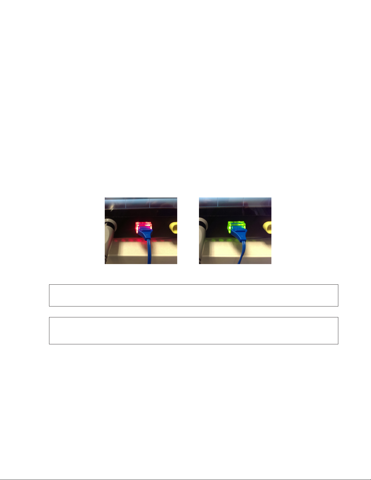
3. When the Patient Return Electrode has been properly selected and applied to the patient, and a
monopolar device has been connected, the Patient Return Electrode receptacle illumination will
change from red to green in color (Figure 4-7).
Figure 4-6. Figure 4-7.
▲ WARNING: Refer to the manufacturer’s instructions for application site and placement procedures when
applying the Patient Return Electrode.
▲ WARNING: Do not depend solely on the illumination indicator for conrmation of good Patient Return
Electrode application. Qualied personnel should make the nal decision on proper Patient Return
Electrode placement.
■ IMPORTANT: Monopolar devices require a Patient Return Electrode. The Generator must detect proper
Patient Return Electrode impedance before the Generator output can be active.
■ IMPORTANT: The AEX™ Generator accepts both single foil and split foil Patient Return Electrodes up to
power levels of 50 watts. If a hand piece with monopolar capability exceeding 50 Watts is connected to
the generator, a split foil Patient Return Electrode is required.
AEX™ Generator Operator’s Manual 4-3
Page 26

Plugging in the Handpiece to the AEX™ Generator
PlasmaBlade™
1. Insert the handpiece connector into the gray PlasmaBlade™ receptacle on the front panel of the AEX™
Generator.
■ IMPORTANT: Upon connection, the Generator will alarm if the device is not recognize the handpiece,
if it fails a unit test, or if it is expired.
2. The screen will display default output levels for Cut and Coag (Figure 4-8).
Figure 4-8. Default Cut and Coag output levels
▲ WARNING: Always stow unused devices in an electrically insulated location such as a safety holster
in sterile eld.
Aquamantys™ Handpiece
1. Insert the handpiece connector into the yellow Aquamantys™ receptacle on the front panel of the AEX™
Generator.
2. The touchscreen will display the default output level for Bipolar power and a glow around the "Prime"
button to prompt saline setup (Figure 4-9).
Figure 4-9. Default Bipolar output level
▲ WARNING: Always stow unused devices in an electrically insulated location such as a safety holster in
sterile eld.
4-4 Operation
Page 27

Combo Handpiece
1. Insert the handpiece connector into the gray PlasmaBlade™ 7-pin receptacle on the front panel of the
AEX™ Generator.
■ IMPORTANT: Upon connection, the Generator will alarm if the device is not recognized as a Combo
handpiece, if it fails a unit test, or if it is expired.
2. The screen will display default output levels and a glow around the "Prime" button to prompt saline setup
(Figure 4-10).
Figure 4-10. Default output levels
● NOTE: If two handpieces with transcollation technology are connected to the generator, the generator
will only permit use of transcollation on the 3-Pin receptacle powered handpiece. Only the 3-Pin
handpiece saline tubing should be loaded in this instance.
Handpiece use requires compatible generator software. If the generator software is not compatible with
its connected handpiece, the handpiece will not function.
▲ WARNING: Always stow unused devices in an electrically insulated location such as a safety holster
in sterile eld.
Loading the Pump Segment Portion of the Handpiece into the Pump Head
of the AEX™ Generator
1. Raise the upper part of the pump head by ipping open the pump lid as shown in Figure 4-11.
Figure 4-11. Open pump lid
AEX™ Generator Operator’s Manual 4-5
Page 28

2. On the handpiece saline tubing, locate the pump segment portion (between black and white tubing
connectors), place the pump segment portion of the saline delivery tubing into the pump head with
the black tubing connector positioned to the left side of the pump head (i.e., closest to the front panel
of the AEX™ Generator). The white tubing connector should then be positioned to the right side of the
pump head (i.e., closest to the back panel of the AEX™ Generator). A label on the front of the pump
indicates the position of the black and white connectors.
Figure 4-12 Open pump lid
■ IMPORTANT: Ensure that the pump segment portion of the saline delivery tubing is properly aligned in
the center of guide slots (upside down “v”) where it enters and exits the pump head.
3. Close the pump head.
The pump segment tubing must be centered in the guide slot of both tubing guides, with no pinching
of the tubing (see Figure 4-13).
Figure 4-13 Closed pump
▲ WARNING: Always close the pump head prior to priming or device activation. Always allow the pump
head rotor to come to a complete stop prior to opening the pump head. Do not attempt to load or
adjust the positioning of the pump segment of the disposable bipolar device in the pump head while
the pump head rotor is turning. Fingers or loose clothing could be caught in the pump rollers.
4-6 Operation
Page 29
Spiking the Saline Bag
1. Hang a bag of sterile saline (0.9% NaCl) solution on the AEX™ Generator Cart I.V. pole or another I.V.
support that is in close proximity to the AEX™ Generator.
2. Remove the protective cover over the spike of the drip chamber at the end of the handpiece’s saline
delivery tubing.
3. Using aseptic technique, spike the bag of sterile saline (0.9% NaCl) solution.
4. Squeeze the drip chamber once or twice to ll the drip chamber to a level of at least one-third full.
Priming the Handpiece
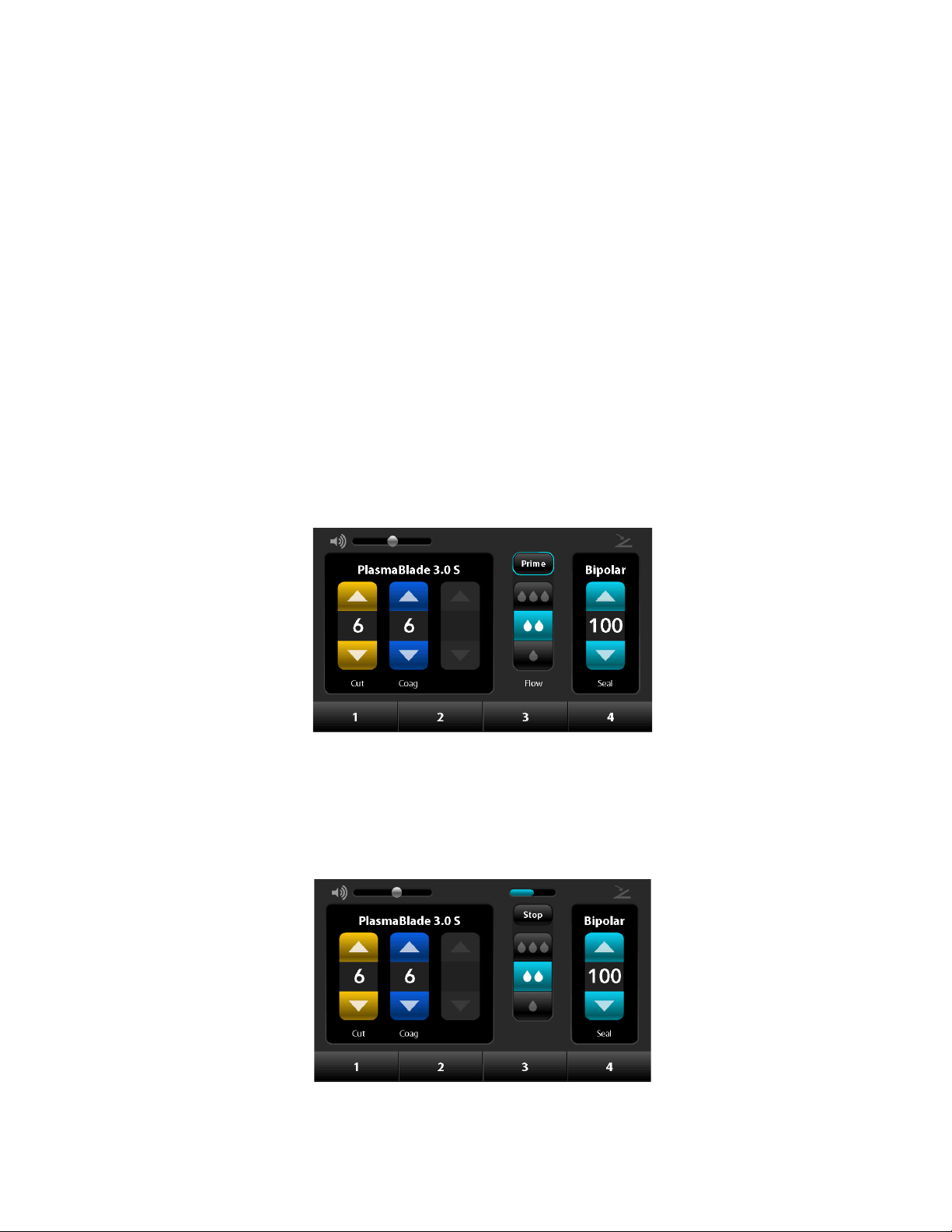
1. Press the “PRIME” button as shown in Figure 4-14. This initiates priming of the handpiece with saline.
• The pump will operate for a preset time period to prime the device. The pump head speed is
accelerated during the priming cycle compared to normal use.
• The device is primed when saline drips from both device electrodes of the handpiece. After the
priming cycle is complete, the pump shuts o automatically.
Figure 4-14. Prime Button Screen
2. The “PRIME” indicator will change to “STOP” when priming is activated. If priming needs to be stopped
after priming has been initiated, press the “STOP” button as shown in Figure 4-15.
Figure 4-15. Stop Button Screen
AEX™ Generator Operator’s Manual 4-7
Page 30

3. After the initial priming of the handpiece, the button is renamed “REPRIME” as shown in Figure 4-16.
Figure 4-16. Reprime Button Screen
▲ WARNING: Always place the handpiece into a holster or over a container to collect the saline that
exits the device electrodes as a result of the priming process. If excess saline is not collected, saline
could drip on the patient, patient drapes, surgical instruments, or operating room surfaces.
▲ WARNING: Lack of saline ow from both of the device electrodes can result in a lack of tissue eect
and may damage the device electrodes during device activation. Use caution to avoid conditions
that can result in lack of adequate saline ow from the device.
Adjusting RF Power Levels
▲ WARNING: Set the RF power to the lowest setting for desired tissue eect to avoid overtreatment,
which could result in swelling, uid, seroma or unintended tissue necrosis. Setting the RF power too
low may produce insucient tissue eect.
1. Set the RF power output for the desired tissue eect by pressing the button to increase, or the
button to decrease, RF power.
2. Release the button when the desired RF power setting is displayed. The nal RF power settings will be
shown on the screen.
■ IMPORTANT: The RF power setting cannot be adjusted while the handpiece is being activated.
3. The default power setting and the range of possible power adjustments will depend upon which
disposable handpiece is inserted into the AEX™ Generator. The range of power settings for each
handpiece have been selected to optimize its performance.
4-8 Operation
Page 31

Adjusting the Saline Flow Rate
1. The saline ow rate may be adjusted by pressing the desired ow rate button. The three ow rate
buttons are:
• High Flow ( )
• Medium Flow ( )
• Low Flow ( )
2. The three possible saline ow adjustments are preset for each given RF power setting.
● NOTE: The saline ow rate setting cannot be adjusted while the disposable hand piece is activated.
3. If a ow rate setting is not manually selected, the medium setting is selected as the default setting.
Activating the Handpiece
The AEX™ Generator is designed to control RF energy output within specications when activated.
If the AEX™ Generator fails to activate, the RF Power Activation Indicator will not illuminate and no audible
indicator will be heard. If the AEX™ Generator fails to meet RF Energy output specications during use, RF
energy output will stop. The generator will alarm and present an error code on the display, indicating to the
operator that an error has occurred.
1. Press the activation button on the handpiece to simultaneously activate RF power and saline ow (if
applicable) from the handpiece. The appropriate indicator on the touch screen will illuminate and the
appropriate activation tone will sound.
2. Release the activation button on the handpiece to shut o both RF power and saline ow from the
handpiece.
At maximum output settings and rated load conditions, the generator may be safely operated at duty cycles
of 33% for bipolar Transcollation (40 seconds on, 80 seconds o), and 25% for monopolar RF delivery (10
seconds on, 30 seconds o).
Using an Optional Footswitch
An optional footswitch may be used. If a footswitch will be used, plug the wireless receiver into the footswitch
connector on the back of the generator (see Figure 2-3 on page 2-4). While using a footswitch, RF power will
be delivered via the handpiece.
AEX™ Generator Operator’s Manual 4-9
Page 32
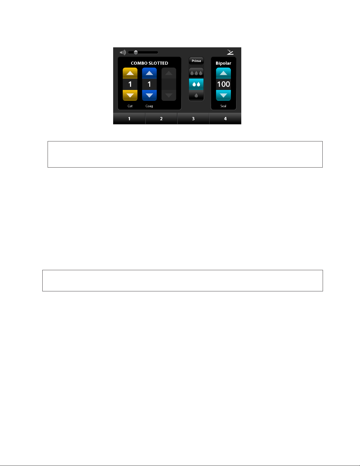
Figure 4-17. Footswitch Connected
▲ WARNING: Ensure that the footswitch is not inadvertently depressed to prevent the device from
being unintentionally activated. Place the footswitch in a location that requires deliberate action
in order to activate the unit.
■ IMPORTANT: Use only the AEX™ Wireless Footswitch.
Adjusting RF Power Settings Using Memory Buttons
Once a Memory Button has been set up with appropriate settings, a user can select a memory button and the
settings that have been preset will automatically become active for the hand pieces that are plugged into the
AEX™ Generator.
Adjusting the Volume of the Activation Tone
▲ WARNING: Do not turn the activation tone down to an inaudible level. The activation tone alerts
the surgical team when a device is active.
• To increase the volume of the RF power activation tone, slide the button to the right.
• To decrease the volume of the RF power activation tone, slide the button to the left.
• The AEX™ Generator prevents this tone from being silenced.
4-10 Operation
Page 33

After Surgery
Disposing of the Handpiece
1. Turn the Generator o by pressing the left half of the power switch.
2. If the handpiece has saline tubing, rmly knot the saline tubing between the drip chamber and the
pump segment.
• Open the pump head and remove the pump segment portion of the saline delivery tubing.
• Remove the used saline bag from I.V. pole.
3. Unplug the handpiece from the AEX™ Generator.
4. Dispose of the handpiece and used saline bag according to the procedures
for your institution.
■ IMPORTANT: Some handpieces and the saline bags will contain unused saline following use of the
handpiece. Take precautions to prevent the unused saline from owing onto operating room surfaces
by placing handpiece into waste receptacle prior to opening pump head and removing device pump
segment.
Preparing the AEX™ Generator for Reuse
▲ WARNING: Electric Shock Hazard. Always turn o and unplug the unit before cleaning.
■ IMPORTANT: Do not clean the unit with abrasive cleaning or disinfectant compounds, solvents, or other
materials that could scratch the panels or damage the unit.
1. Turn the AEX™ Generator o by pressing the left hand portion of the power switch.
2. Unplug the main power cord from the wall outlet and receptacle on the AEX™ Generator.
3. Thoroughly wipe all surfaces of the unit and power cord with a damp cloth using a mild cleaning solution
or disinfectant. Follow the procedures approved by your institution or use a validated infection control
procedure. Do not allow uids to enter the chassis. The unit should not be sterilized.
AEX™ Generator Operator’s Manual 4-11
Page 34

Transportation and Storage of the AEX™ Generator
Care should be taken when transporting the AEX™ Generator prior to and after use to prevent impact damage
to the unit. The unit should be transported on the AEX™ Generator Cart or a suitable alternative. Consult the
procedures for your institution and applicable regulations.
If the unit is stored at a temperature outside its normal operating range of 50 °F to 104 °F (10 °C to 40 °C),
allow it to stabilize at room temperature prior to use.
The unit can be stored indenitely. However, if you store it longer than one year, you must perform specic
checkout procedures, including functional verication before use.
Do not store the AEX™ Generator on its side or end. This may cause damage to the unit.
■ IMPORTANT: Do not discard in trash. Electronic equipment should be disposed of in an appropriate
manner by a certied disposal company.
4-12 Operation
Page 35

5. Cleaning and Maintenance
This section contains information for ordinary cleaning and maintenance of the AEX™ Generator. While
the Generator has been designed and manufactured to high industry standards, periodic inspection and
performance testing must be performed by a qualied biomedical technician for safe and eective operation.
● NOTE: Refer to the AEX™ Service Guide for more detailed information and instructions.
Inspections Required Before Each Use
1. Visually inspect the Generator for physical damage. Report damage to Medtronic Advanced Energy or
your biomedical department. Do not use the Generator if it is damaged.
2. Visually inspect the power cord and plug for physical damage. Replace the cord if the insulation has been
breached. Do not use the Generator if the cord or plug has been damaged and has not yet been replaced.
Required Annual Inspections
1. Inspect the tightness of the power plug. If this component is loose, it must be replaced with a Medtronic
Advanced Energy approved component.
2. Inspect the mating, cleanliness, and absence of damage to the patient connectors. Do not use the
Generator if the connectors are damaged.
3. Inspect for accumulation of lint or debris on the Generator or fan vents. Do not use the Generator if lint or
debris has accumulated and has not been cleared.
Cleaning
▲ WARNING: Electric shock hazard. Always unplug the Generator from the wall outlet prior to cleaning.
The Generator does not require sterilization.
1. Clean the front display, cover, and cord with a mild detergent or mild disinfecting solution and damp cloth.
It is recommended that non-ammable agents be used for cleaning and disinfection whenever possible.
If ammable agents are used for cleaning, disinfecting, or as solvents, they should be allowed to dry
before surgery.
◆ CAUTION: Do not allow uids to enter the chassis. Do not use alcohol, caustic, corrosive, or abrasive
materials on the front display, cover, and cord, as they may cause damage to the equipment. Medtronic
Advanced Energy recommends following hospital procedures for cleaning the outside of the Generator
after each procedure.
Refer to the AEX™ Wireless Footswitch Operator’s Manual for detailed cleaning instructions for the footswitch
and receiver.
AEX™ Generator Operator’s Manual 5-1
Page 36

Maintenance
The AEX™ Generator must be performance tested by a hospital qualied biomedical technician at least every
year. Follow your hospital’s procedures for periodic performance verication of electrosurgical generators.
Medtronic Advanced Energy recommends performing a Power Output verication check for each mode of
operation.
Service
The RS-232 port provided on the rear panel is used for the following service features, which can be performed
by a qualied Medtronic Advanced Energy technician only:
• To reprogram set-up parameters.
• To download the event history log containing information on errors and faults.
Storage
The Generator must be thoroughly checked by a qualied biomedical engineer if it has been stored for longer
than 6 months.
Allow the Generator to remain at room temperature for at least 1 hour if it has been stored at extreme
temperatures. Refer to “Storage Parameters” on page7-1 for the limits for storing the AEX™ Generator.
Environmental Protection
Retain the shipping container and packing material in the event that the Generator needs to be returned for
repair or service. At the end of the equipment’s life, dispose of it in accordance with your local regulations.
The materials in the generator include aluminum, steel, copper, thermoplastics, and electronic components.
5-2 Cleaning and Maintenance
Page 37

6. Troubleshooting
This section identies the possible error and fault conditions and oers common solutions for correcting
malfunctions and responding to alarms.
The AEX™ Generator has been designed and manufactured for reliable operation. In the event that the
Generator fails, it has several self-diagnostic routines to aid in troubleshooting the problem. If the software
detects a problem, an error code or fault code is displayed on the screen, and the Generator is disabled. The
Generator will remain disabled until the detected problem is corrected. The self-diagnostic routines are only an
aid for qualied technicians, and are not a substitute for evaluation of a problem by a qualied technician.
▲ WARNING: Electric shock hazard. Always unplug the Generator from the wall outlet prior to opening the
cover for servicing. There are no user-serviceable parts inside the Generator. The AEX™ Generator should
only be serviced by a Medtronic Advanced Energy trained technician.
Monopolar and Bipolar Errors
The AEX™ Generator includes automatic self-diagnostics. If the diagnostics detect a condition that can be
corrected by the operator, the system displays an error code, sounds an alarm tone, and deactivates the
Generator’s output. Correcting the error will enable the Generator’s output.
Most error codes result from conditions in accessories attached to the Generator. The following table lists the
error codes and describes the condition.
Table 6-1. Error Codes
Error Code Description
E1 Switch on handpiece may be stuck in the ON position.
E2 Footpedal switch may be stuck in the ON position.
E3 Patient Return Electrode has poor connection.
E4 Generator monopolar output error.
E5 Handpiece has reached end of life.
E6 Handpiece is not recognized as a Medtronic Advanced Energy device or failed test.
E7 Generator bipolar output.
E8 Monopolar output circuitry has exceeded a normal temperature.
E9 Patient Return Electrode is not supported by current handpiece.
E10 Handpiece must be Primed before performing Transcollation.
AEX™ Generator Operator’s Manual 6-1
Page 38

Error Code Details
A detailed description of the cause of each error is provided below, along with steps to follow. Figure 6-1
shows an example of an Error screen.
Figure 6-1. Error Code E1
Error Code E1
Switch on handpiece may be stuck in the ON position.
Cause Solution
Handpiece button stuck in the
ON position when the device
is connected. The Error Code
is displayed and the alarm will
sound once.
1. Ensure that the handpiece is not in contact with the patient.
2. Disconnect and reconnect the handpiece.
3. If the Error Code reappears, turn the Generator power OFF and then turn the
power ON again.
4. If the problem persists, replace the handpiece and repeat this procedure.
5. If the Error Code reappears, record the number and contact Medtronic Advanced
Energy Customer Service. Do not use the Generator.
Error Code E2
Foot pedal switch may be stuck in the ON position.
Cause Solution
Footswitch has pedal switch
stuck in the ON position when
the footswitch is connected.
The Error Code is displayed
and the alarm will sound once.
1. Ensure that the handpiece is not in contact with the patient.
2. Disconnect and reconnect the footswitch.
3. If the Error Code reappears, turn the Generator power OFF and then turn the
power ON again.
4. If the problem persists, replace the footswitch and repeat this procedure.
5. If the Error Code reappears, record the number and contact Medtronic Advanced
Energy Customer Service. Do not use the Generator.
6-2 Troubleshooting
Page 39

Error Code E3 with Red LED Illumination
Patient Return Electrode has poor connection or no connection.
Cause Solution
The Error Code is displayed when
the impedance is out of range.
The Error Code is displayed and
the alarm will sound once. The
error/alarm will only display/
sound if the handpiece is
activated. The Patient Return
Electrode receptacle LED
Illumination will turn red and stay
red as long as the impedance
is out of range. The Patient
Return Electrode impedance is
continuously checked.
1. Follow the manufacturer’s instructions for Patient Return Electrode placement.
2. Verify that a Split Foil Patient Return Electrode is used for handpieces with power
levels greater than 50 watts.
3. Verify that the Patient Return Electrode is connected to the Generator.
4. Verify the Patient Return Electrode is making proper contact with the patient.
5. Disconnect and reconnect the Patient Return Electrode and Generator.
If the Error Code reappears, record the number and contact Medtronic Advanced
Energy Customer Service. Do not use the Generator.
Error Code E4
Generator monopolar output error.
Cause Solution
Measurements of the monopolar
output voltage and current are
being made while the Generator
has active output. If these
measurements are outside the
normal range, the output will
be disabled. The Error Code is
displayed and the alarm will
sound once.
1. If the Error Code reappears, replace the handpiece.
2. If the Error Code reappears, disconnect the handpiece and the Patient Return
Electrode. Turn the Generator power OFF and then turn the power ON again.
Reconnect the handpiece and Patient Return Electrode and try again.
3. If the Error Code reappears, record the number and contact Medtronic Advanced
Energy Customer Service. Do not use the Generator.
Error Code E5
Handpiece has reached end of life.
Cause Solution
For safety reasons, each device
has a limited active life span. If the
time is exceeded, then the Error
Code is displayed and the alarm
will sound once.
1. Replace the handpiece.
2. The Error Code screen will disappear if the device is recognized, tested, and has
a life expectancy.
3. If the Error Code reappears, record the number and contact Medtronic Advanced
Energy Customer Service. Do not use the Generator.
Error Code E6
Handpiece is not recognized as compatible.
Cause Solution
The handpiece is connected to the
Generator and it is not recognized as
an AEX™ device, a generator software
update is needed, or it has failed
testing. The Error Code is displayed
and the alarm will sound once.
1. Replace the handpiece. The Error Code screen will disappear if the device is
recognized, tested, and has a life expectancy.
2. If the Error Code reappears, record the number and contact Medtronic Advanced
Energy Customer Service. Do not use the Generator.
AEX™ Generator Operator’s Manual 6-3
Page 40

Error Code E7
Generator bipolar output error.
Cause Solution
Measurements of the bipolar
output voltage and current are
being made while the Generator
has active output. If these
measurements are outside the
normal range, the output will
be disabled. The Error Code is
displayed and the alarm will
sound once.
1. If the Error Code reappears, replace the handpiece.
2. If the Error Code reappears, disconnect the handpiece and the Patient Return
Electrode. Turn the Generator power OFF and then turn the power ON again.
Reconnect the handpiece and Patient Return Electrode and try again.
3. If the Error Code reappears, record the number and contact Medtronic Advanced
Energy Customer Service. Do not use the Generator.
Error Code E8
Monopolar output circuitry has exceeded a normal temperature.
Cause Solution
Intensive use of high power
output can cause signicant
increase in the generator circuit
temperature. If the temperature
is determined to exceed a normal
level, the monopolar transcollation
output will be disabled. The error
code is displayed and the alarm
will sound once.
1. Release the transcollation button on the handpiece.
2. Cut and Coag use may be continued.
3. The error code will remain on the screen until the generator circuit temperature
has returned to a normal level. While the error code is displayed, monopolar
transcollation will be deactivated.
Error Code E9
Patient Return Electrode is not supported by current handpiece.
Cause Solution
The connected handpiece has
the capability of delivering
greater than 50 Watts of
monopolar RF power. A device
with this capacity can only be
used with a split foil Patient
Return Electrode. The output will
be disabled if the unlocked NE
Impedance measures less than 18
Ohms while such a handpiece is
connected.
The Error Code will be displayed
and the alarm will sound once.
1. Substitute a Split foil Patient Return Electrode for the Patient Return Electrode
currently connected to the receptacle on the front of the generator.
2. If the Error Code reappears, disconnect the handpiece and the Patient Return
Electrode. Turn the Generator power OFF and then turn the power ON again.
Reconnect the handpiece and Patient Return Electrode and try again.
3. If the Error Code reappears, record the number and contact Medtronic Advanced
Energy Customer Service. Do not use the Generator.
6-4 Troubleshooting
Page 41

Error Code E10
Handpiece needs to be primed before performing Transcollation.
Cause Solution
The generator requires that
all connected handpieces are
primed before they can perform
Transcollation. The Error Code
is displayed and the alarm will
sound once upon un-primed
Transcollation activation attempt.
1. Press the Prime button on the display.
2. Allow the priming sequence to complete or press the Stop button to end priming.
3. Attempt Transcollation activation again.
4. If the Error Code reappears, record the number and contact Medtronic Advanced
Energy Customer Service. Do not use the Generator.
Monopolar and Bipolar Faults
The AEX™ Generator includes automatic self-diagnostics. If the diagnostics detect a fault, the system displays
a fault code, sounds an audible tone, and deactivates the Generator’s output. All faults indicate a possible
problem with the equipment. Power must be turned o and then back on before operation can continue. If
the self-test does not successfully complete, refer the equipment to Service Personnel.
Table 6-2. Fault Codes
Non-Recoverable
Fault Code
Description
F1 Internal temperature of the Generator has exceeded the limit.
F2 CRC self-test fault.
F3 RF Module not calibrated or calibration was lost.
F4 Real Time Clock self-test fault.
F5 Watchdog Monitor has detected a Watchdog Processor failure.
F6 Controller Processor communication with the Display has failed.
F7 Pump Communications fault.
F8 Pump Control Overheating.
F9 ADC Reference fault.
F10 RAM self-test fault.
AEX™ Generator Operator’s Manual 6-5
Page 42
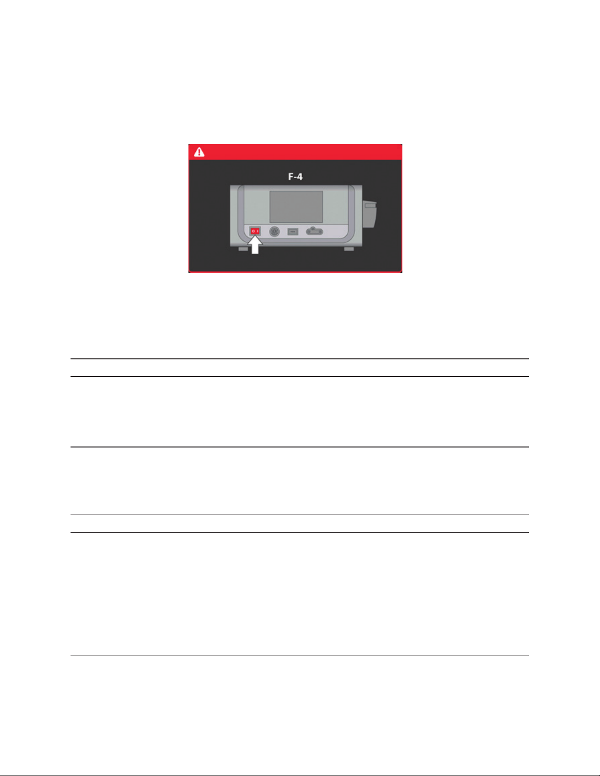
Fault Code Details
A detailed description of the cause of each fault code is provided below, along with steps to follow. Figure 6-2
shows an example of a Fault screen.
Figure 6-2. Fault Code
Fault Code F1
Internal temperature of the Generator has exceeded the limit.
Cause Solution
Internal temperature exceeded
limit while turned ON. The Fault
Code is displayed and the alarm
will sound once.
1. Turn o Generator and turn back on after the Generator has cooled suciently.
2. If the Fault Code reappears, record the number and contact Medtronic Advanced
Energy Customer Service. Do not use the Generator.
Fault Code F2
CRC self-test fault.
Cause Solution
Self-test diagnostics are run
when the Generator is powered
ON. This Fault Code indicates that
one or more of the self-tests have
failed. The Fault Code is displayed
and the alarm will sound
continuously.
1. Turn the Generator power OFF and then turn the power ON again. Do not press
buttons or activate handpieces during the self-test.
2. If the Fault Code reappears, disconnect the handpiece and Patient Return
Electrode. Turn the Generator power OFF and then turn the power ON again.
3. If the Fault Code reappears, record the number and contact Medtronic Advanced
Energy Customer Service. Do not use the Generator.
6-6 Troubleshooting
Page 43

Fault Code F3
RF Module not calibrated or calibration was lost.
Cause Solution
The RF Module has detected that
it is not calibrated or calibration
values have been lost. The Fault
Code is displayed until the
Generator is turned o and the
alarm will sound once.
1. Turn the Generator power OFF and then turn the power ON again. Reconnect the
handpiece and Patient Return Electrode and re-attempt use of the handpiece.
2. If the Fault Code reappears, record the number and contact Medtronic Advanced
Energy Customer Service. Do not use the Generator.
Fault Code F4
Real Time Clock self-test fault.
Cause Solution
Self-test diagnostics are run
when the Generator is powered
ON.
This Fault Code indicates that
one or more of the self-tests
have failed. The individual selftest that failed will be recorded
in the Generator’s data ash for
retrieval during maintenance. The
Fault Code is displayed until the
Generator is turned o and the
alarm will sound once.
1. Turn the Generator power OFF and then turn the power ON again. Reconnect the
handpiece and Patient Return Electrode and re-attempt use of the handpiece.
2. If the Fault Code reappears, record the number and contact Medtronic Advanced
Energy Customer Service. Do not use the Generator.
Fault Code F5
Watchdog Monitor has detected a Watchdog Processor failure.
Cause Solution
The Watchdog Monitor has
detected that the Processor
Watchdog has engaged. The
Fault Code is displayed until the
Generator is turned o and the
alarm will sound once.
1. Turn the Generator power OFF and then turn the power ON again. Reconnect the
handpiece and Patient Return Electrode and re-attempt use of the handpiece.
2. If the Fault Code reappears, record the number and contact Medtronic Advanced
Energy Customer Service. Do not use the Generator.
AEX™ Generator Operator’s Manual 6-7
Page 44

Fault Code F6
Controller Processor communication with the Display has failed.
Cause Solution
The Controller processor has
detected that the display
communication is not
functioning properly. The Fault
Code is displayed until the
Generator is turned o and the
alarm will sound once.
1. Turn the Generator power OFF and then turn the power ON again. Reconnect the
handpiece and Patient Return Electrode and re-attempt use of the handpiece.
2. If the Fault Code reappears, record the number and contact Medtronic Advanced
Energy Customer Service. Do not use the Generator.
Fault Code F7
Pump Communications fault.
Cause Solution
The Pump motor controller
communications have failed. The
Fault Code is displayed and the
alarm will sound once.
1. Turn the Generator power OFF and then turn the power ON again. Reconnect the
handpiece and Patient Return Electrode and re-attempt use of the handpiece.
2. If the Fault Code reappears, record the number and contact Medtronic Advanced
Energy Customer Service. Do not use the Generator.
Fault Code F8
Pump Overheating.
Cause Solution
The temperature of the pump’s
motor controller exceeded limit
while turned ON. The Fault Code
is displayed and the alarm will
sound once.
1. Turn o Generator and turn back on after the Generator has cooled suciently.
2. If the Fault Code reappears, record the number and contact Medtronic Advanced
Energy Customer Service. Do not use the Generator.
Fault Code F9
ADC Reference fault.
Cause Solution
This Fault Code indicates that
the Generator’s analog to
digital conversion circuitry has
experienced a fault while turned
ON. The Fault Code is displayed
and the alarm will sound once.
1. Turn the Generator power OFF and then turn the power ON again. Reconnect the
handpiece and Patient Return Electrode and re-attempt use of the handpiece.
2. If the Fault Code reappears, record the number and contact Medtronic Advanced
Energy Customer Service. Do not use the Generator.
6-8 Troubleshooting
Page 45

Fault Code F10
RAM self-test fault.
Cause Solution
Self-test diagnostics are run when
the Generator is powered ON.
This Fault Code indicates that
one or more of the self-tests have
failed. The Fault Code is displayed
until the Generator is turned o
and the alarm will sound once.
1. Turn the Generator power OFF and then turn the power ON again. Reconnect the
handpiece and Patient Return Electrode and re-attempt use of the handpiece.
2. If the Fault Code reappears, record the number and contact Medtronic Advanced
Energy Customer Service. Do not use the Generator.
Error Codes and Error Handling
The AEX™ Generator self-test, which is executed immediately following power up, comprises several phases.
The rst phase covers the internal RAM and the MPU0 watchdog test. The second phase tests the major
computer hardware components (microcontroller). The third phase tests the NV-RAM and the separate RFGEN
modules for potential errors. Portions of this self-test are repeated in the background during normal use.
If an error is detected, the respective test is repeated at least once in order to exclude sporadic deviations.
If the deviation remains, the self-test aborts, an error message is generated, and the unit enters the safe state.
The safe state disables functions of the pump generator until the error condition is cleared.
AEX™ Generator Operator’s Manual 6-9
Page 46

Troubleshooting Malfunctions
If a solution is not readily apparent, use the table below to help identify and correct specic malfunctions.
After you troubleshoot the malfunction, verify that the unit completes the self-test as described in
Section 4, Operation.
Table 6-3. Troubleshooting
Situation Possible Cause Solution
No power No power cord. Use power cord shipped with AEX™ Generator or
contact Medtronic Advanced Energy Customer Service
to obtain new power cord.
Wrong power cord utilized. Use power cord shipped with AEX™ Generator or
contact Medtronic Advanced Energy Customer Service
to obtain new power cord.
Faulty wall outlet. Insert power cord into a functioning wall outlet.
Fuse drawer is open or fuses are blown. Close the fuse drawer. Replace the blown fuse(s).
Wrong fuse. Use fuse listed in Section 7, Specications. Correct fuse
is also listed on back panel of the unit.
Unit not turned on. Switch unit on using the power switch located on the
front panel of the unit.
No saline when device
activated
Insucient insertion of device plug into receptacle. Ensure disposable handpiece is fully inserted into
receptacle.
Insucient insertion of power cord into unit or wall
jack.
Damaged AEX™ Generator power cord. Contact Medtronic Advanced Energy Customer Service
Damaged disposable handpiece power cord. Do not use device. Return the device to Medtronic
Pump tubing segment not inserted correctly into
pump head.
Saline bag positioned on side or upside down. Ensure saline bag is positioned right side up.
Pump head not closed. Close the pump head prior to use.
No saline source. Ensure spike at end of device tubing set is correctly
Priming cycle not completed. Press “PRIME” button once and ensure priming cycle
Priming button on unit pressed before the saline bag
was spiked.
Inadequate supply of saline. Ensure drip chamber is at least one-third (1/3) full.
Ensure power cord is fully inserted into back of unit and
wall jack.
to obtain a new power cord.
Advanced Energy and use new device.
Remove pump tubing segment from pump head and
reinsert correctly as indicated in User Guide.
inserted into a 250 ml or larger I.V. bag of sodium
chloride solution (0.9%NaCI).
completes and saline drips from both device electrodes.
Press “PRIME” button once and ensure priming cycle
completes and saline drips from both device electrodes.
Replace used bag of sodium chloride solution
(0.9%NaCI) with a new bag.
6-10 Troubleshooting
Page 47

Table 6-3. Troubleshooting (continued)
Situation Possible Cause Solution
No saline when device
activated (continued)
Pump tubing segment inserted in reverse
orientation.
Saline line kinked/compressed/occluded. Ensure disposable handpiece pump segment is
Non-AEX™ handpieces connected to AEX™ Generator. Ensure device connected to AEX™ Generator is an AEX™
Ensure black connector on the tubing segment is
oriented to the left side of the pump head and the
white connector to the right side of the pump head
when pump tubing segment is inserted.
properly aligned in the pump head. Ensure saline line is
not kinked, compressed, or occluded by operating room
equipment, instruments, or personnel.
handpiece. If incorrect handpiece is being utilized,
discard and utilize correct disposable handpiece.
Incorrect saline ow
when device activated
All saline slots in either of the device electrodes
of the handpiece clogged by tissue or coagulated
blood.
Pump is jammed by pump segment connector which
has inadvertently entered into pump head.
Source of normal saline is a non-vented glass bottle. Open vent cap on handpiece drip chamber.
Pump tubing segment not inserted correctly into
pump head.
Saline bag height below pump head. Ensure saline bag is positioned at a height above the
Saline delivery tubing inserted into pump head
instead of pump tubing segment.
Air bubbles in line due to incorrect priming
technique.
Saline line kinked or compressed. Ensure pump segment is properly aligned in the pump
Clean device electrodes with gauze. Ensure precautions
are taken to avoid inadvertent device activation when
cleaning device electrodes. If this does not correct
the problem, discontinue use and return device to
Medtronic Advanced Energy and use new device.
Ensure pump segment is aligned in the center of guide
slots (upside down “v”) where it enters and exits the
pump head.
Remove pump tubing segment from pump head and
reinsert correctly as indicated in User Guide.
pump head.
Ensure black connector on the tubing segment is
oriented to the left side of the pump head and the
white connector to the right side of the pump head
when pump tubing segment is inserted.
Press “PRIME” button once to reprime the device in
order to remove air bubbles.
head. Ensure saline line is not kinked, compressed, or
occluded by OR equipment, instruments, or personnel.
Incorrect (non-AEX™) disposable handpiece utilized. Ensure device connected to AEX™ Generator is an AEX™
handpiece. If incorrect handpiece is being utilized,
discard and utilize correct AEX™ disposable handpiece.
One or more of the saline slots in either of the device
electrodes of the handpiece clogged by tissue or
coagulated blood.
Handpiece pump segment is not inserted into pump
head.
Clean device electrodes with gauze. Ensure precautions
are taken to avoid inadvertent device activation when
cleaning device electrode.
If this does not correct the problem, return device to
Medtronic Advanced Energy and use new device.
Insert pump tubing segment into pump head as shown
in User Guide.
AEX™ Generator Operator’s Manual 6-11
Page 48

Table 6-3. Troubleshooting (continued)
Situation Possible Cause Solution
Generator doesn’t
work
AEX™ Generator damaged. Contact Biomedical Engineering Department or
a Medtronic Advanced Energy representative for
assistance. Use a backup AEX™ Generator or traditional
techniques to complete the surgical procedure if
repairs cannot be made prior to the scheduled surgical
procedure.
AEX™ Generator did not receive a scheduled safety
check.
AEX™ Generator plugged into an inappropriate wall
outlet (e.g. not protected against ground fault, etc.).
Contact Biomedical Engineering Department or
a Medtronic Advanced Energy representative for
assistance. Use a backup AEX™ Generator or traditional
techniques to complete the surgical procedure if
repairs cannot be made prior to the scheduled surgical
procedure. See Section 5, Cleaning and Maintenance, for
maintenance schedule.
Plug AEX™ Generator into an appropriate wall outlet
prior to use.
Unit is on, but did not
complete self-test
Unit is on and
disposable handpiece
is activated, but unit
does not deliver
output
Interference with
other device only
when the unit is
activated
Continuous monitor
interference
Software or internal component malfunction. Turn o, and then turn on the unit. If the fault code
reappears:
•RecordtheerrorcodenumberandrefertoFault Code
Details in this section.
•UseabackupAEX™Generatorortraditional
techniques to complete the surgical procedure.
Power setting is too low. Increase the power. Refer to Section 4, Operation,
Adjusting RF Power Levels. Use the lowest possible
power setting needed to obtain the desired surgical
eect.
Malfunctioning handpiece or improper handpiece
connection.
A malfunction condition exists.
Metal-to-metal sparking. Check all connections to the unit and handpiece.
Electrically inconsistent ground wires in the
operating room.
Faulty chassis-to-ground connections. Check and correct the chassis ground connections for
Turn o the unit. Check the device connection. If
device continues to malfunction, replace device and
contact Medtronic Advanced Energy to report device
malfunction.
Check the power display for an error code. Note the
code number and refer to Error Code Details in this
section.
Verify that all ground wires are as short as possible and
go to the same grounded metal.
the monitor and for the unit.
Monitor responding to radiated frequencies. Check other electrical equipment in the room for
Abnormal
neuromuscular
stimulation (Stop
surgery immediately)
Metal-to-metal sparking. Check all connections to the unit and device.
6-12 Troubleshooting
defective grounds. If not resolved, contact Biomedical
Engineering Department to check with the monitor
manufacturer.
Page 49

Table 6-3. Troubleshooting (continued)
Situation Possible Cause Solution
Ineective hemostasis Power setting too low.
Tissue under-treated. Tissue not treated long
enough to result in a reduction in intraoperative or
postoperative blood loss.
Wrong uid used for device irrigation.
Device electrode(s) of disposable handpiece clogged
by tissue or coagulated blood.
Excessive blood, uid or saline in surgical eld where
device is being utilized.
Unintended tissue
eect
Excessive saline Saline ow rate setting too high.
Error codes Error codes appear.
Power setting too high.
Tissue over-treated.
Non-AEX™ handpieces utilized.
Excess saline resulting from priming cycle.
2nd (or more) activation of priming cycle.
O tissue handpiece activation.
Saline delivery tubing inserted into pump head
instead of pump tubing segment.
Pump head disengaged following procedure prior to
rmly knotting the saline delivery tubing between
the drip chamber and the pump segment on the
handpiece.
Increase the power. Refer to Section 4, Operation,
Adjusting RF Power Levels. Use the lowest possible power
setting needed to obtain the desired surgical eect.
See disposable handpiece Instructions For Use
and/or device treatment guides for treatment
recommendations.
Only utilize sterile bag of sodium chloride solution
(0.9%NaCI) with the AEX™ System.
Clean device electrodes with gauze. Ensure precautions
are taken to avoid inadvertent device activation when
cleaning device electrodes. If this does not correct the
problem, return device to Medtronic Advanced Energy
and use new device.
Utilize appropriate suction to remove blood, uid and/
or saline. See disposable handpiece Instructions For
Use and/or handpiece treatment guides for treatment
recommendations.
Decrease the power. Refer to Section 4, Operation,
Adjusting RF Power Levels.
See disposable handpiece Instructions For Use
and/or device treatment guides for treatment
recommendations.
Ensure device connected to AEX™ Generator is an AEX™
handpiece. If incorrect handpiece is being utilized,
discard and utilize correct disposable handpiece.
Decrease saline ow rate. Refer to Section 4, Operation,
Adjusting the Saline Flow Rate.
Place the device into a holster or over a container to
collect the saline that will exit the device electrodes as a
result of the priming process.
Place the device into a holster or over a container to
collect the saline that will exit the device electrodes as a
result of the priming process.
Only activate the disposable handpiece on/over
tissue intended to be treated. Activation over
another location may result in hot saline run-o onto
unintended tissue, patient, patient drapes, hospital
sta, and operating room surfaces.
Ensure black connector on the disposable pump
segment is oriented to the left side of the pump head
and the white connector to the right side of the pump
head when pump tubing segment is inserted.
The disposable handpiece and the saline bag will
contain unused saline following use of the device.
Firmly knot the saline delivery tubing between the drip
chamber and the pump segment on the device prior to
opening the pump head.
Turn power o for a minimum of 10 seconds, turn
power back on. If error code still displays, contact
Medtronic Advanced Energy.
If problem persists after applying the appropriate solution indicated in this table, use a backup AEX™ Generator or traditional techniques
to complete the surgical procedure. Contact Medtronic Advanced Energy Customer Service for assistance.
AEX™ Generator Operator’s Manual 6-13
Page 50

This page intentionally left blank.
6-14 Troubleshooting
Page 51

7. Specications
AEX™ Generator
All specications are nominal and are within ±20% of a stated value at room temperature (77 °F/25 °C) and
a nominal input power voltage. All specications are subject to change without notice.
General
Classification:
Type:
Internal Design:
Output Configuration:
Cooling:
Designed to Meet:
Dimensions and Weight
Width:
Length:
Height:
Weight:
Operating Parameters
Temperature:
IEC 60601-1, Class I
CF
Solid state
Isolated (RF Floating)
Forced air (fan)
ES60601-1; IEC 60601-1, 60601-1-4, 60601-1-2, 60601-2-2;
CAN/CSA C22.2 NO. 601.1.
14.5 in (36.8 cm)
17 in (43.2 cm)
6.5 in (16.5 cm)
<20 lb (9 kg)
10 °C to 40 °C
Humidity:
Storage Parameters
Temperature:
Humidity:
Shipping Conditions for
Packaged Unit:
Atmospheric Pressure:
15% to 85% relative humidity, non-condensing
–20 °C to 65 °C
0% to 85% Non-condensing relative humidity
–20 °C to 65 °C; 15–85% relative humidity, non-condensing
600 to 795 mmHg (800-1060 hPa)
AEX™ Generator Operator’s Manual 7-1
Page 52

Audio Specications
The audio levels stated below are for activation tones (Cut, Coag, and Seal) and error indicator tones
(Patient Return Electrode and system alarms) at a distance of one meter. Error indicator tones meet
the requirements for IEC 60601-2-2.
Volume: >43 to 65 dBa, adjustable >65 dBa, not adjustable
Activation Tone Error Indicator Tone
Frequency:
Duration:
Mono Cut: 1109 Hz
Mono Coag: 554 Hz
Bipolar Seal: 932 Hz
Simultaneous Mono Cut and
Bipolar Seal: 330 Hz
Simultaneous Mono Coag and
Bipolar Seal: 415 Hz
Continuous while the
Generator is activated
Table 7-1. Mains Input Characteristics
An 8 note sequence alternating between
1865Hz and 1480Hz
¼ second duration for each note,
total sequence duration of 2 seconds.
Mains Input Characteristics
Frequency
Hz
50/60 115/230 100 240 8A - 4A 10A
Nominal Minimum Maximum Maximum
Mains Voltage (V) Mains Current (A)
Fuses
Low Frequency (50/60Hz) Leakage Current
• Earth leakage current in normal condition <5 mA
• Earth leakage current in single-fault condition <10 mA
• Enclosure (touch) leakage current in normal condition <100 µA
• Enclosure (touch) leakage current in single fault condition <500 µA
• Patient leakage current in normal condition <10 µA
• Patient leakage current in single fault condition <50 µA
7-2 Specifications
Page 53

High Frequency (RF) Leakage Current
• Monopolar RF leakage current <150 mA
• Bipolar RF Leakage Current <100 mA
Table 7-2. Output Characteristics
Output Characteristics
Power
Mode
Low Cut 0.5 to 20 100 1365 469 0.17 to 4.3
Medium Cut 0 to 90 500 585 469 100
High Cut 10 to 50 500 1300 469 37.8 to 66.78
Low Coag 0 to 50 500 1500 469 23.8
High Coag 10 to 50 1000 2600 469 16
Bipolar 20 to 220 100 175 (nom) 469 100
(watts
Typical)
Rated
Load
(ohms)
Maximum
Open Circuit
Voltage (Vpk)
Operating
Frequency
(kHz Typical)
Duty Cycle
(% Typical )
User Duty Cycle
• Cut Mode: 10 seconds ON, 30 seconds OFF
• Coag Mode: 10 seconds ON, 30 seconds OFF
• Bipolar Mode: 40 seconds ON, 80 seconds OFF
Patient Return Electrode Contact Quality Monitor
The system continuously monitors the impedance across the Patient Return Electrode. The system
presents audible and visible error indication when it senses a loss of contact quality for the Patient
Return Electrode. When the error condition exists, the system deactivates output power.
Single Foil: Once the system establishes the single foil Patient Return Electrode
impedance (>18 Ω), an increase of 10 Ω or more will cause a Patient
Return Electrode has poor or no connection “E3” error indication.
Using a combo device with a monopolar power capability above 50
Watts will cause a Patient Return Electrode Incompatible “E9” error
indication.
Split Foil: Once the system establishes the split foil Patient Return Electrode
impedance (18 to 135 Ω), an increase greater than 30% or
above 135 Ω will cause a Patient Return Electrode has poor or no
connection “E3“ error indication.
AEX™ Generator Operator’s Manual 7-3
Page 54

Electromagnetic Compatibility
The AEX™ Generator conforms to electromagnetic compatibility standard EN/IEC 60601-1-2.
Compliance was veried with the following accessories connected to the AEX™ Generator:
Table 7-3. Attached Accessory Cables
Accessory Cable Description Cable Length (meters)
AC mains power cord 4.6
PlasmaBlade™ device 3.0
Aquamantys™ device 3.2
Patient Return Electrode 2.75
Footswitch receiver 1.2
RS-232 cable 1.8
USB cable 1.8
■ IMPORTANT: Medical Electrical Equipment needs special precautions regarding EMC and needs to
be installed and put into service according to the EMC information provided in this section.
Portable and Mobile RF Communications can aect Medical Electrical Equipment.
Use of the AEX™ Generator is not restricted to specic shielded environments.
Table 7-4. Electromagnetic Emissions
The AEX™ Generator is intended for use in the electromagnetic environment specied below.
The customer or user of the AEX™ Generator should assure that it is used in such an environment.
Emissions Test Compliance Electromagnetic Environment – Guidance
RF emissions
CISPR11
RF emissions
CISPR11
Harmonics
IEC 61000-3-2
Flicker
IEC 61000-3-3
Group 1
Class A The AEX™ Generator is suitable for use in all establishments, other
Class A
Complies
●
NOTE:
The EMISSIONS characteristics of this equipment
make it suitable for use in industrial areas and hospitals (CISPR
11 class A). If it is used in a residential environment (for which
CISPR 11 class B is normally required) this equipment might not
oer adequate protection to radio-frequency communication
services. The user might need to take mitigation measures, such
as relocating or re-orienting the equipment.
than domestic, and those directly connected to the public lowvoltage power supply network that supplies buildings used for
domestic purposes.
▲WARNING: This equipment/system is intended for use by
healthcare professionals only. This equipment/system may
cause radio interference or may disrupt the operation of nearby
equipment. It may be necessary to take mitigation measures,
such as re-orienting or relocating the AEX™ Generator or
shielding the location.
7-4 Specifications
Page 55

Table 7-5. Electromagnetic Immunity
The AEX™ Generator is intended for use in the electromagnetic environment specied below.
The customer or user of the AEX™ Generator should assure that it is used in such an environment.
Immunity Test IEC 60601 Test Level Compliance Level
ESD
EN 61000-4-2
EFT
IEC 61000-4-4
Surge
IEC 61000-4-5
Voltage Dips/
Dropout
IEC 61000-4-11
±6 kV contact
±8 kV air
±2kV Mains
±1kV I/Os
±1 kV Dierential
±2 kV Common
>95% Dip for 0.5 Cycle
60% Dip for 5 Cycles
30% Dip for 25 Cycles
>95% Dip for 5 sec.
±6 kV contact
±8 kV air
±2kV Mains
±1kV I/Os
±1 kV Dierential
±2 kV Common
>95% Dip for 0.5 Cycle
60% Dip for 5 Cycles
30% Dip for 25 Cycles
Note 1
Electromagnetic Environment
Guidance
Floors should be wood, concrete, or
ceramic tile. If oors are synthetic, the
relative humidity should be at least
30%.
Mains power quality should be that
of a typical commercial or hospital
environment.
Mains power quality should be that
of a typical commercial or hospital
environment.
Mains power quality should be that
of a typical commercial or hospital
environment. If the user of the
AEX™ Generator requires continued
operation during power mains
interruptions, it is recommended that
the AEX™ Generator be powered from
an uninterruptible power supply or a
battery.
Power frequency
(50/60 Hz)
Magnetic Field
IEC 61000-4-8
3 A/m 3 A/m Power frequency magnetic elds
should be that of a typical commercial
or hospital environment.
NOTE 1: The EUT powers down during a 5 second loss of AC Mains power, but recovers into Standby Mode as soon as
power is restored. This meets the manufacturer’s requirements for maintaining Basic Safety and Risk Management.
AEX™ Generator Operator’s Manual 7-5
Page 56

Table 7-5. Electromagnetic Immunity (continued)
Immunity
Test IEC 60601-1-2 Test Level Compliance Level
Conducted RF
IEC 61000-4-6
Radiated RF IEC
61000-4-3
3 V/m
150 kHz – 80 MHz
3 V/m
80 MHz – 2.5 GHz
(V1)=3 Vrms Portable and mobile communications
(E1)=3 V/m
Electromagnetic Environment Guidance
equipment should be separated from
the AEX™ Generator by no less than the
distances calculated/listed below:
D=(3.5/V1)(Sqrt P)
150kHz to 80MHz
D=(3.5/E1)(Sqrt P)
80 to 800 MHz
D=(7/E1)(Sqrt P)
800 MHz to 2.5 GHz
where P is the max power in watts and D
is the recommended separation distance
in meters.
Field strengths from xed transmitters,
as determined by an electromagnetic
site survey, should be less than the
compliance levels (V1 and E1).
Interference may occur in the vicinity of
equipment containing a transmitter.
Other Specications
Power Cord: Generators have a power entry connector to allow connection with a US Hospital
Grade power cord or an EU plug power cord. Units accept 100–240 VAC at a
frequency of 50/60 Hz, fused at 10 amps.
Display Size: 7 in diagonal (3.5 in tall x 6 in wide)
7-6 Specifications
Page 57

Output Characteristic Curves
Figure 7-1. Output Power vs Impedance for Low Cut
EN
25
20
15
10
Output Power, W
5
0
0500 1000 1500 2000
AEX™ Low Cut
Ohms
Power, MID
Power, MAX
Figure 7-2. Output Power vs Impedance for Medium Cut
100.00
90.00
80.00
70.00
60.00
50.00
40.00
30.00
Output Power, W
20.00
10.00
0.00
0500 1000 1500 2000
AEX™ Medium Cut
Ohms
Power, MID
Power, MAX
Figure 7-3. Output Power vs Impedance for High Cut
60
50
40
30
20
Output Power, W
10
0
0500 1000 1500 2000
AEX™ High Cut
Ohms
Power, MID
Power, MAX
AEX™ Generator Operator’s Manual 7-7
Page 58

Figure 7-4. Output Power vs Impedance for Low Coag
01
40
35
30
25
20
15
Output Power, W
10
5
0
0500 1000 1500 2000
AEX™ Low COAG
Ohms
Power, MID
Power, MAX
Figure 7-5 Output Power vs Impedance for High Coag
AEX™ High COAG
Power, MID
Power, MAX
Output Power, W
60
50
40
30
20
10
0
0500 1000 1500 2000
Ohms
Figure 7-6. Output Power vs Impedance for Bipolar
250
200
150
100
Output Power, W
50
0
0200 400600 80
AEX™ Bipolar
Ohms
Power, MID
Power, MAX
000
7-8 Limited Warranty
Page 59

Figure 7-7. Output Power vs Impedance for Monopolar
AEX™ Monopolar
Output Power, W
Ohms
Power, MID
Power, MAX
AEX™ Generator Operator’s Manual 7-9
Page 60

This page intentionally left blank.
7-10 Specifications
Page 61

8. Limited Express Warranty and Disclaimers
Limited Express Warranty
Medtronic Advanced Energy LLC warrants the AEX™ Generator against defects in materials or workmanship
under normal use and preventive maintenance for the respective warranty periods shown below. Medtronic
Advanced Energy will repair or replace the unit without charge, at its option, of any product, or part thereof,
which has been returned to Medtronic Advanced Energy LLC or its Distributor within the applicable time
period shown below. This warranty does not apply to any product or part that has been adversely aected
due to use with devices manufactured or distributed by parties not authorized by Medtronic Advanced
Energy LLC; repaired or altered outside Medtronic Advanced Energy’s factory; subjected to improper use,
negligence or accident or not used in accordance with the instructions provided in this manual. Standard
hospital preventive maintenance procedures should be followed and performed by qualied biomedical
service personnel and are not covered in the warranty.
• Medtronic Advanced Energy’s products are warranted for the following periods after delivery to the
original purchaser:
• AEX™ Generator - One (1) Year, Parts and Labor
• AEX™ Wireless Footswitch - One (1) Year, Parts and Labor
Disclaimer of Implied Warranties and Consequential Damages
MEDTRONIC ADVANCED ENERGY LLC MAKES NO OTHER WARRANTIES WITH RESPECT
TO THE PRODUCT AND EXPRESSLY DISCLAIMS ALL OTHER WARRANTIES, EXPRESS OR
IMPLIED, AS TO MERCHANTABILITY, FITNESS FOR A PARTICULAR PURPOSE OR ANY OTHER
MATTER. IN NO EVENT SHALL MEDTRONIC ADVANCED ENERGY LLC BE LIABLE FOR ANY
INDIRECT, CONSEQUENTIAL OR SPECIAL DAMAGES OF ANY KIND. THE REMEDIES SET
FORTH IN THE LIMITED EXPRESS WARRANTY ARE THE EXCLUSIVE REMEDIES AVAILABLE
TO CUSTOMER.
AEX™ Generator Operator’s Manual 8-1
Page 62

This page intentionally left blank.
8-2 Limited Warranty
Page 63

9. Product Accessories
The following accessories are compatible for use with the AEX™ Generator. Only Medtronic Advanced Energy
recommended accessories should be used with the Generator.
• PlasmaBlade™ Monopolar handpieces
• Aquamantys™ Bipolar Disposable handpieces
• PlasmaBlade™ and Aquamantys™ Combination handpieces
• AEX™ Wireless Footswitch
• Standard Patient Return Electrode
• Single Foil – Valleylab™ Standard PolyHesive™ II E7506 and E7508
• Split Foil – Adult REM Valleylab™ PolyHesive™ II E7507 and E7509
- 3M1179 corded adult REM™ pads
• Compatible with Aquamantys™ and AEX™ Carts
AEX™ Generator Operator’s Manual 9-1
Page 64

This page intentionally left blank.
9-2 Product Accessories
Page 65

10. Glossary
This section provides denitions of terms relating to electrosurgery. The information below is provided as a
convenience and should not be interpreted as an authoritative discussion of the subject.
active electrode The device electrode or electrode assembly at which the electrosurgical eect is
blend A modied cut waveform incorporating some o-time, thus allowing tissue to cool, and
coagulation The clotting of blood or dehydration of tissue with no cutting eect. Electrosurgical
cutting Occurs when intense sparks focus the energy and vaporize the tissue. It results from high
intended. It usually has a small contact surface area and provides a high current
density to achieve the desired surgical eect.
providing varying degrees of hemostasis.
coagulation often incorporates intermittent bursts of high-voltage, low-current
electricity.
current density in the tissue causing cellular uid to burst into steam and disrupt the
structure. Voltage is low and current ow is high. In order to induce a cutting eect in
human tissue, voltage must exceed 200 Vp.
desiccation A procedure where a small amount of surface tissue is dried out by placing the active
electrode in contact with the tissue. Desiccation diers from fulguration in that peak
voltage is lower resulting in the inability of the current to arc through air to tissue. Direct
contact between electrode and tissue is required. See fulguration.
disposable accessory An electrosurgical accessory, such as active electrodes, handles, dispersive electrodes, etc.
It is not intended to be used more than once.
duty cycle The proportion of time (expressed in percentage) that a current or device is on versus
o. Duty cycle may be used when referring to current waveforms that are repetitive. Thus
high-frequency current would be on using a shorter period of time than a low-frequency
current. Duty cycle is also used in reference to electrical components or equipment. For
example, some equipment is designed to be used continuously, that is, with a duty cycle
rating of 100%, while other equipment may be rated for intermittent use, that is less than
100% duty cycle. Most ESU’s are designed to be used intermittently. Typically, they are
rated for 25% duty cycles. Use of any equipment beyond its duty cycle rating may result
in premature failure.
electrosurgery (surgical
diathermy)
The generation and delivery of radio frequency current between an active electrode and
a Patient Return Electrode for the purposes of dehydration of tissue. Electrosurgery also
includes cutting or vaporizing (tissue explosion). In contrast to electrocautery, the electric
current actually passes through the patient.
AEX™ Generator Operator’s Manual 10-1
Page 66

electrosurgical accessory Equipment used in conjunction with the electrosurgical generator to accomplish
electrosurgery. These include, but are not limited to footswitch, cable, Patient Return
Electrode, and active electrode.
fulguration
(spray technique)
impedance (measured in
ohms)
mode
(operating)
monopolar The traditional form of electrosurgical circuit, which uses an active electrode to apply
Patient Return Electrode The electrode at which no electrosurgical eect is intended or desired. It is usually large
Coagulating tissue or blood by means of radio frequency electric arcs. In contrast to
desiccation, the active electrode is not in good electrical contact with the tissue, and arcs
jump from the active electrode to the tissue.
Total opposition, both resistive and reactive, a circuit oers to the ow of alternating
current at a given frequency.
Each of the distinct ways in which the electrosurgical unit can be operated with
electrosurgical output, for example, monopolar cutting, monopolar coagulation,
monopolar blended, monopolar spray (fulguration).
the therapeutic current to the surgical site, and a Patient Return Electrode to return the
current to the ESU.
in area in order to provide a low current density so that no electrosurgical eect occurs
at that site. It is also known as a patient plate, patient pad, return pad, plate electrode,
return electrode, neutral electrode, dispersive electrode or inactive electrode. It is
sometimes (inaccurately) referred to as a grounding plate.
power The rate at which energy is produced or consumed. Power is equal to voltage multiplied
by current, or resistance multiplied by current squared. The unit of measure of power is
the watt.
Transcollation The eect of RF energy applied concurrently with saline resulting in hemostatic sealing
and coagulation of soft tissue and bone without charring.
10-2 Glossary
Page 67

11. Symbols
The following symbols are used on the product and/or packaging.
Symbol Description
Table 11-1. Symbols
Debrillation-proof type CF equipment
RF Isolated - Patient connections are isolated from earth at high frequency
Warning: Dangerous voltage
Power ON - To indicate connection to voltage mains
Power OFF - To indicate disconnection from voltage mains
UP button - To increase the output level
DOWN button - To decrease the output level
Speaker volume control
Footswitch
Caution: Pinch Hazard - Keep ngers clear of rollers
To reduce the risk of electric shock, do not remove the cover. Refer servicing to qualied personnel.
Consult instructions for use
Model number
Serial number
Date of manufacture
AEX™ Generator Operator’s Manual 11-1
Page 68

Symbol Description
C US
Equipotential ground
Caution: Consult accompanying documents
Non-ionizing radiation
Explosion risk if used in the presence of ammable anesthetics
Separate collection of waste at end of life as required by European Directives.
Dispose of in accordance with the applicable country regulation.
Table 11-1. Symbols (continued)
. .
TUV Rheinland
In accordance with IEC 60601-1, ES 60601-1, and IEC 60601-2-2; CAN/CSA C22.2 NO. 601.1.
Manufacturer
Do not operate in oxygen enriched environments
Caution: Federal law (USA) restricts this device to sale by or on the order of a physician.
Axed in accordance with European Council Directive 93/42/EEC.
Authorized European Representative
Fragile, Handle with Care
Keep Dry
Temperature Limitation
Humidity Limitation
Atmospheric Pressure Limitation
This Way Up
11-2 Symbols
Page 69

Page 70

MEDTRONIC ADVANCED ENERGY LLC
180 International Drive
Portsmouth, NH 03801 USA
+1 866 777 9400
Authorized European Representative
Medtronic B.V.
Earl Bakkenstraat 10
6422 PJ Heerlen
The Netherlands
+31 45 566 8000
Authorized Australian Representative
Medtronic Australasia Pty Ltd.
5 Alma Road
Macquarie Road NSW 2113 Australia
www.medtronicadvancedenergy.com
manuals.medtronic.com
© Copyright 2016, 2017
Medtronic Advanced Energy LLC
70-10-1455 Rev G
2017/07
 Loading...