

Page 1

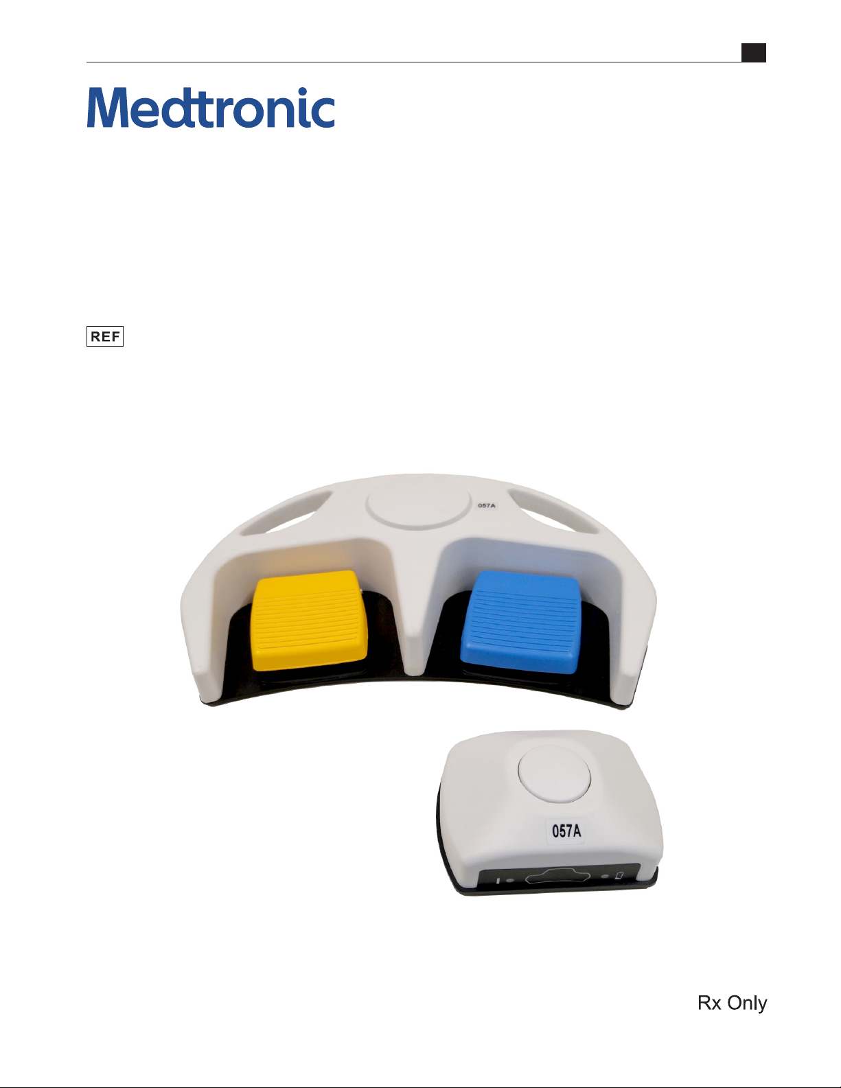
RF Footswitch
Operator’s Manual
34-109-1
Page 2

Page 3
RF Footswitch
Operator’s Manual
34-109-1
EN
Page 4

EN
Copyright and
Trademarks
Disclaimer
© 2019 Medtronic. All rights reserved. Medtronic, Medtronic logo and Further, Together
are trademarks of Medtronic. All other brands are trademarks of a Medtronic company.
No part of this publication may be reproduced, transmitted, transcribed, stored in retrieval
systems, or translated into any form, or by any means: electronic, mechanical, magnetic,
optical, or otherwise, without the prior written permission of Medtronic Navigation, Inc.
826 Coal Creek Circle, Louisville, CO 80027, United States of America.
Medtronic reserves the right to change its products and services at any time to incorporate
the latest technological developments. This guide is subject to change without notice.
Federal (USA) law restricts this device to sale by or on the order of a physician.
Customer Service Telephone Numbers:
US +1 800 595 9709
Intl. +1 720 890 3160
Page 5

Contents
1. Preface
Indications for Use ................................................................................................................................................................................. 1-1
Device Description ....................................................................................................................................................................... 1-1
Safety .......................................................................................................................................................................................................... 1-1
General Use ..................................................................................................................................................................................... 1-1
Denitions of Terminology ................................................................................................................................................................. 1-2
Warnings and Cautions ........................................................................................................................................................................1-3
2. The RF Footswitch
The RF Footswitch ..................................................................................................................................................................................2-1
Channel/Coding ............................................................................................................................................................................ 2-1
3. Operation
The RF Footswitch ..................................................................................................................................................................................3-1
EN
4. Cleaning and Maintenance
Transmitter ............................................................................................................................................................................................... 4-1
Receiver ..................................................................................................................................................................................................... 4-1
5. Specications
RF Footswitch .......................................................................................................................................................................................... 5-1
General .............................................................................................................................................................................................. 5-1
Dimensions and Weight .............................................................................................................................................................. 5-1
Certication ..................................................................................................................................................................................... 5-2
Electromagnetic Interference ................................................................................................................................................... 5-2
6. Limited Express Warranty and Disclaimers
Limited Express Warranty....................................................................................................................................................................6-1
Disclaimer of Implied Warranties and Consequential Damages .......................................................................................... 6-1
7. Symbols
Symbols ..................................................................................................................................................................................................... 7-1
RF Footswitch Operator’s Manual i
Page 6

EN
List of Figures
Figure 2-1. AEX™ Generator, RF Footswitch ................................................................................................................................2-1
Figure 2-2. Receiver Front View .......................................................................................................................................................2-2
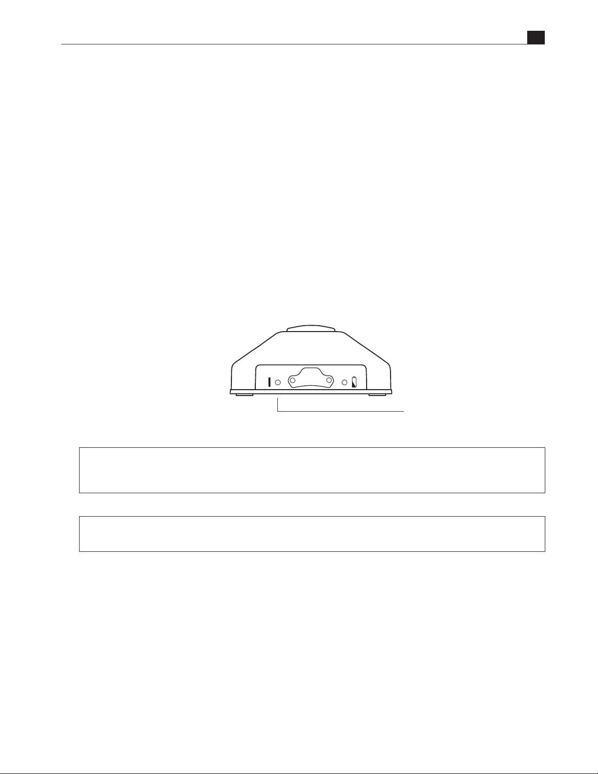
Figure 2-3. Receiver Rear View .........................................................................................................................................................2-3
Figure 2-4. Transmitter .......................................................................................................................................................................2-3
Figure 3-1. Wireless Receiver ............................................................................................................................................................3-1
Figure 4-1. Transmitter Battery Replacement ............................................................................................................................ 4-2
Table 7-1. Symbols ................................................................................................................................................................................7-1
ii
Page 7

1. Preface
Indications for Use
The RF Footswitch is an accessory that is indicated for use to provide foot switch input control to the AEX™
Generator (40-405-1).
Device Description
The RF Footswitch is an accessory to the AEX™ Generator. The foot switch provides input control to the AEX™
Generator which utilizes a switch closure (on/o) to activate Medtronic monopolar and bipolar disposable
electrosurgical handpieces. Use of the optional wireless foot switch in conjunction with the wireless receiver
(connected to the AEX™ Generator) provides CUT & COAG power to Medtronic monopolar and bipolar
handpieces.
EN
Safety
The information presented in this section is important for the safety of both the patient and the operator
and also serves to enhance equipment reliability. This section describes how the terms Warning, Caution,
Important, and Note are used throughout the manual.
General Use
If the foot switch is cold to the touch or below ambient temperature, allow it to stabilize before use.
The use of accessory equipment not complying with the equivalent safety requirements of this equipment
may lead to a reduced level of safety of the resulting system.
Consideration relating to the choice shall include:
• use of the accessory in the patient vicinity
• evidence that the safety certication of the accessory has been performed in accordance
to the appropriate IEC 60601-1 and/or IEC 60601-1-2 harmonized national standard.
Periodically, whenever the integrity of the switch is in doubt, test all functions.
RF Footswitch Operator’s Manual 1-1
Page 8

EN
Denitions of Terminology
Four types of special notice are used throughout this manual. They are: Warning, Caution, Important, and
Note. The warnings and cautions in this safety section relate to the equipment in general and apply to all
aspects of the foot switch. Be sure to read the other chapters because there are additional warnings and
cautions, which relate to specic features of the foot switch.
▲ WARNING: A warning indicates a hazardous condition that may result in injury or death if not corrected
or avoided.
◆ CAUTION: A CAUTION indicates a potentially hazardous situation which, if not avoided, may result in
minor or moderate injury. Cautions are also used to avoid damage to equipment.
■ IMPORTANT: An IMPORTANT notice indicates an emphasized note. It is something you should be
particularly aware of, something not readily apparent.
● NOTE: A NOTE indicates a particular point of information, something on which to focus your
attention.
1-2 Preface
Page 9

Warnings and Cautions
The warnings and cautions presented in this manual should be read, understood and followed for safety
purposes.
▲ Warning for Accidental Spills: In the event that uids are accidentally spilled on the receiver, take the
receiver out of operation and inspect for damage.
▲ Warning for Electric Shock Hazard. To reduce the risk of electrical shock do not remove any covers.
Refer servicing to qualied personnel.
▲ Warning for Explosion Hazard: Do not use this equipment in the presence of ammable anesthetics.
EN
▲ Warning for Interfacing to Equipment: Foot switches must be interfaced with other equipment.
Be certain to consult manufacturer’s specications to maintain safe operation.
◆ Caution for Annual Servicing: For continued safety and performance of the switch, it is recommended
that the functionality and electrical safety of the switch be veried on an annual basis.
◆ Caution for Daily Testing: It is essential that the foot switch be inspected every day or before use.
◆ Cautions for Performance:
• The wireless foot switch system operates in the Frequency range of 2.405 to 2.408 GHz. It should be tested
to assure compatibility with any device it is connected to or environment in which it is working.
• Report all problems experienced with the foot switch. If the foot switch is not working properly, contact
your service representative for service. The foot switch should not be used if it is not working properly.
RF Footswitch Operator’s Manual 1-3
Page 10

EN
This page intentionally left blank.
1-4 Preface
Page 11
2. The RF Footswitch
The RF Footswitch
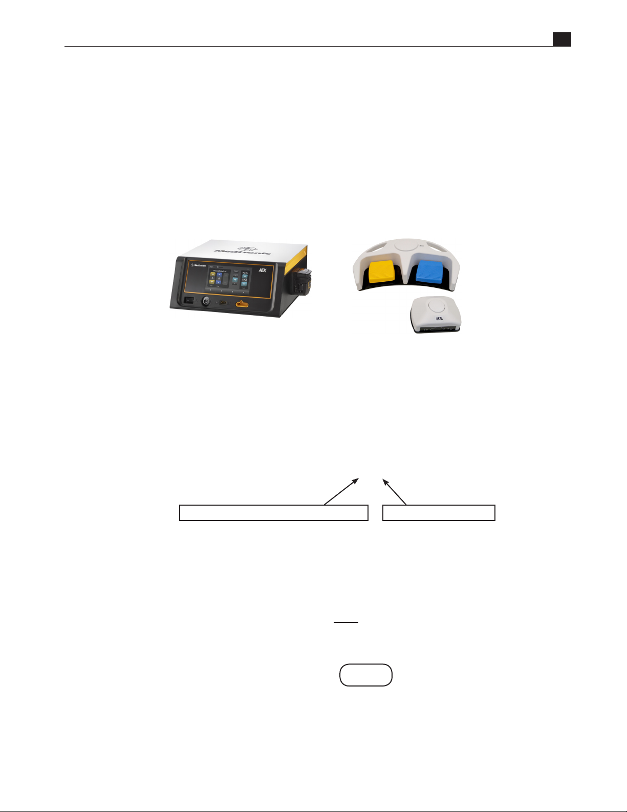
The RF Footswitch is one component of the (Medtronic/AEX™) Surgery System. The Generator provides radio
frequency (RF) energy to disposable electrosurgical handpieces.
Figure 2-1. AEX™ Generator, RF Footswitch
EN
AEX™ Generator
RF Footswitch
Channel/Coding
The radio frequency foot switch has fteen distinct channel capabilities. This allows multiple channels to be
used in the same area simultaneously. The channel is identied in the serial number of the units. See example
below. The channel also appears on a label on top of the units.
XXXXXXXX T001
In addition to the fteen channels, each manufacturer has its own code encryption. This assures that dierent
manufacturers with the same channel marking can be used in the same area simultaneously with no
interference. The manufacturer’s code is embedded into the model number as shown below. It also appears
on a label on the top of the units.
Alpha digit designates transmitter or receiver
SP-9970214-XXX XXXXXX
Last digit designates channel
These three digits denote the manufacturer’s code.
Example A :
UNIT LABEL: The rst two or three digits denote the manufacturer code; the last digit is the channel.
RF Footswitch Operator’s Manual 2-1
XXX
Page 12
EN
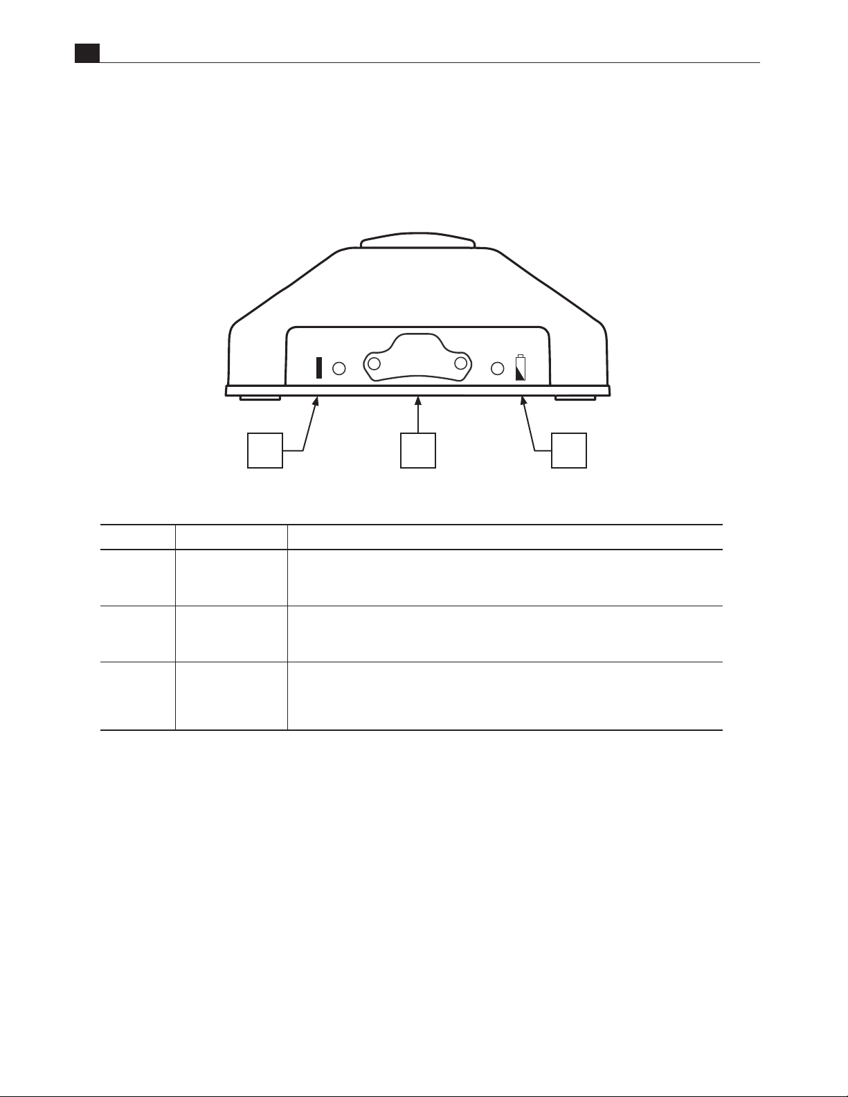
Receiver Front View
Figure 2-2. Receiver Front View
A B C
Name Description
A Power On indicator The Power On indicator lights green to indicate the unit is powered
B Switch function
Indicators
C Low battery
indicator foot
switch
LED’s will light when switch(es) are actuated.
Red LED will ash when the batteries are close to the end of their life. The LED will
ash for 3-4 hours. When LED stays on constantly there is 3-4 hours of battery life
remaining. However batteries should be replaced immediately.
2-2 The RF Footswitch
Page 13
Receiver Rear View
Description
EN
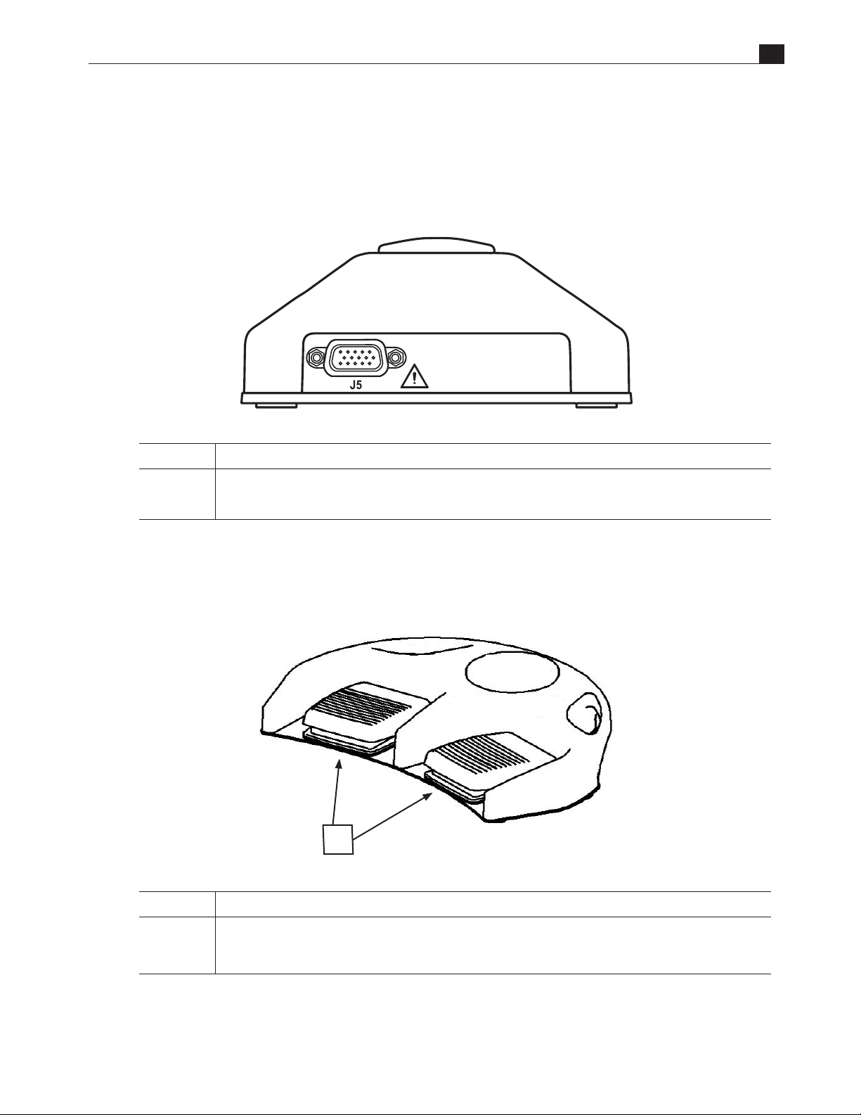
Figure 2-3. Receiver Rear View
J5 Output Connector: For connection of interface cable to the Medtronic/AEX™ Generator.
Transmitter
Figure 2-4. Transmitter
A
Description
A Primary switches
Single or Dual Function
RF Footswitch Operator’s Manual 2-3
Page 14

EN
This page intentionally left blank.
2-4 The RF Footswitch
Page 15
3. Operation
The RF Footswitch
● NOTE: The wireless foot switch is only compatible with enabled handpieces.
1. Plug the wireless receiver into the foot switch connector on the back of the Medtronic/AEX™ Generator
using the appropriate interface cable. While using a foot switch, RF power will be delivered via the
handpiece.
2. Turn on the Medtronic/AEX™ Generator and ensure that the wireless receiver’s power-on LED is green,
indicating that the receiver is powered on.
Figure 3-1. Wireless Receiver
EN
Power-On
▲ WARNING: Ensure that the foot switch is not inadvertently depressed to prevent the device from being
unintentionally activated. Place the foot switch in a location that requires deliberate action in order to
activate the unit.
▲ WARNING: Only the primary surgeon using the handpiece should operate the foot switch. Unintentional
activation may occur if the foot switch is activated by a separate user, which may result in patient or user injury.
LED Indicator
RF Footswitch Operator’s Manual 3-1
Page 16

EN
This page intentionally left blank.
3-2 Operation
Page 17

4. Cleaning and Maintenance
The following cleaning instructions are provided.
◆ CAUTIONS:
• ABRASION: Do not use abrasive cloth, sharp objects, or abrasive cleaners.
• DISCONNECTION: Detach the interconnect cables from the receiver.
• IMMERSION: Do not immerse the receiver, cables or connectors under running water.
Transmitter
The transmitter is IP68 rated and can be completely immersed briey.
EN
Dampen a non-abrasive cloth with one of the following products; then wring out until slightly wet and gently
rub soiled area until clean.
• Isopropyl alcohol
• Soap and water
• Cidex
• Sodium Hypochlorite 5.25% (Bleach) diluted 10:1
Receiver
◆ CAUTION: The receiver is IPX1 rated and cannot be immersed.
Dampen a non-abrasive cloth with one of the following products; then wring out until slightly wet and gently
rub soiled area until clean.
• Isopropyl alcohol
• Soap and water
• Cidex
• Bleach Sodium Hypochlorite 5.25% (Bleach) diluted 10:1
Wipe any uids from the surface of the receiver.
RF Footswitch Operator’s Manual 4-1
Page 18
EN
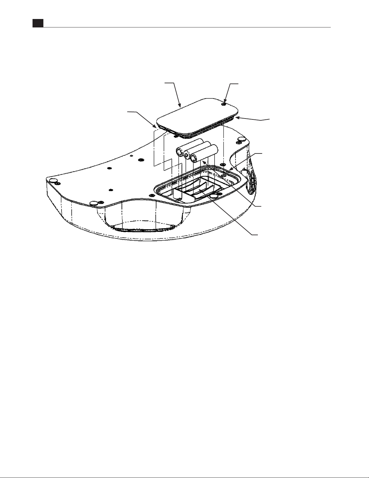
Battery Replacement
Figure 4-1. Transmitter Battery Replacement
2X LOCKING TABS
BATTERY COVER
SLOTTED DRIVE
1/4 TURN FASTENER
“O” RING SEAL
RECESSED AREA FOR COVER REMOVAL
(GENTLY PRY FLAT TIP DEVISE TO
REMOVE COVER)
3X “AA” BATTERIES
3X BATTERY POLARITY INDICATOR
ON BOTTOM FACE OF HOLDER
Replace the batteries in the transmitter with high quality “AA” size Alkaline batteries as shown.
◆ CAUTIONS:
• Never mix manufacturers when replacing the batteries.
• Never mix old and new batteries.
• Care must be taken when replacing the batteries not to damage the o-ring seal on the battery cover.
• The o-ring seal should be replaced whenever it is damaged or its integrity is in question.
• Medtronic Navigation, Inc. recommends the seal should be replaced at the minimum every third time batteries
are replaced. When replacing the seal lubricate it with petroleum jelly.
• Battery Leakage: If the transmitter will not be used for an extended period of time, remove the batteries to
prevent damage due to possible battery leakage.
• Battery Disposal: Follow the battery manufacturer’s recommendations or your hospital policy for the
disposal of used batteries.
4-2 Cleaning and Maintenance
Page 19

5. Specications
RF Footswitch
All specications are subject to change without notice.
General
EN
Range:
Switch functions:
Latency:
Power consumption
(transmitter):
Power requirements
(receiver):
Receiver output:
Communication:
Frequency:
Encryption:
Transmitter:
Receiver:
Dimensions and Weight
Typically 30 feet (9.14 m)
Maximum of 2
Typically 100 milliseconds
Stand-by 2ua
6VDC @ 200ma
SPST relay, 0.5 amp contacts
IEEE802.15.4 Compliant
2.4 GHz
None - Only sensor data transferred
EN 60529 Degree of protection IP68
EN 60529 Degree of protection IPX1
Transmitter
Width:
Length:
Height:
Weight:
14.0 in (35.5 cm)
10.0 in (25.4 cm)
2.63 in (6.68 cm)
5.5 lbs (2.49kg) w/batteries
Receiver
Width:
Length:
Height:
Weight:
5.0 in (12.7 cm)
3.5 in (8.89 cm)
2.2 in (5.72 cm)
0.45 lbs (0.204kg)
RF Footswitch Operator’s Manual 5-1
Page 20

EN
Certication
IEC/UL 60601-1
CAN/CSA C22.2 No. 60601-1
Classied to IEC/UL 60601-1 Medical electrical equipment by
Underwriter’s Laboratories, Inc. with respect to re, shock, and
mechanical hazards.
Classied with respect to electric shock, re, mechanical, and
other specied hazards only.
Electromagnetic Interference
This device has been tested and found to comply with the limits for medical devices to the EN 60601-1-2
(2002), Medical Device Directive 93/42/EEC. These limits are designed to provide reasonable protection
against harmful interference in a typical medical installation.
However, because of the proliferation of radio-frequency transmitting equipment and other sources of
electrical noise in the health-care and home environments it is possible that high levels of such interference
due to close proximity or strength of a source, may result in disruption of performance of this device.
This equipment generates, uses, and can radiate radio frequency energy and, if not installed and used
in accordance with these instructions, may cause harmful interference with other devices in the vicinity.
Disruption or interference may be evidenced by erratic or incorrect functioning. If this occurs, the site of use
should be surveyed to determine the source of this disruption, and actions taken to eliminate the source.
The user is encouraged to try to correct the interference by one of the following measures:
• Turn equipment in the vicinity o and on to isolate the oending equipment.
• Reorient or relocate the other receiving device.
• Increase the separation between the interfering equipment and this equipment.
• If assistance is required, contact your Medtronic Navigation, Inc. Representative.
5-2 Specifications
Page 21

6. Limited Express Warranty and Disclaimers
Limited Express Warranty
For one (1) year from the date of shipment from Medtronic Navigation, Inc., if an RF Footswitch is found,
to Medtronic Navigation, Inc.’s satisfaction, to be inoperable during normal and proper use in accordance
with applicable instructions, Medtronic Navigation, Inc. will repair or replace the product, at its sole option,
provided the product is returned, freight prepaid, in accordance with all return packaging and shipping
instructions. A product repaired or replaced under this warranty will be warranted for the remainder of the
original warranty period.
Disclaimer of Implied Warranties and Consequential Damages
MEDTRONIC NAVIGATION, INC. MAKES NO OTHER WARRANTIES WITH RESPECT TO THE
PRODUCT AND EXPRESSLY DISCLAIMS ALL OTHER WARRANTIES, EXPRESS OR IMPLIED, AS
TO MERCHANTABILITY, FITNESS FOR A PARTICULAR PURPOSE OR ANY OTHER MATTER. IN NO
EVENT SHALL MEDTRONIC NAVIGATION, INC. BE LIABLE FOR ANY CONSEQUENTIAL DAMAGES.
THE ABOVE WARRANTY IS VOID ON ANY PRODUCT WHICH HAS BEEN MODIFIED OR REPAIRED
OTHER THAN BY MEDTRONIC NAVIGATION, INC. OR AN AUTHORIZED REPRESENTATIVE,
IMPROPERLY INSTALLED, USED, MAINTAINED OR STORED, OR SUBJECT TO ABUSE, MISUSE,
NEGLECT OR ACCIDENT. MEDTRONIC NAVIGATION, INC. IS NOT RESPONSIBLE FOR DAMAGE OR
ANY OTHER LOSS DURING RETURN SHIPMENT.
EN
RF Footswitch Operator’s Manual 6-1
Page 22

EN
This page intentionally left blank.
6-2 Limited Express Warranty and Disclaimers
Page 23
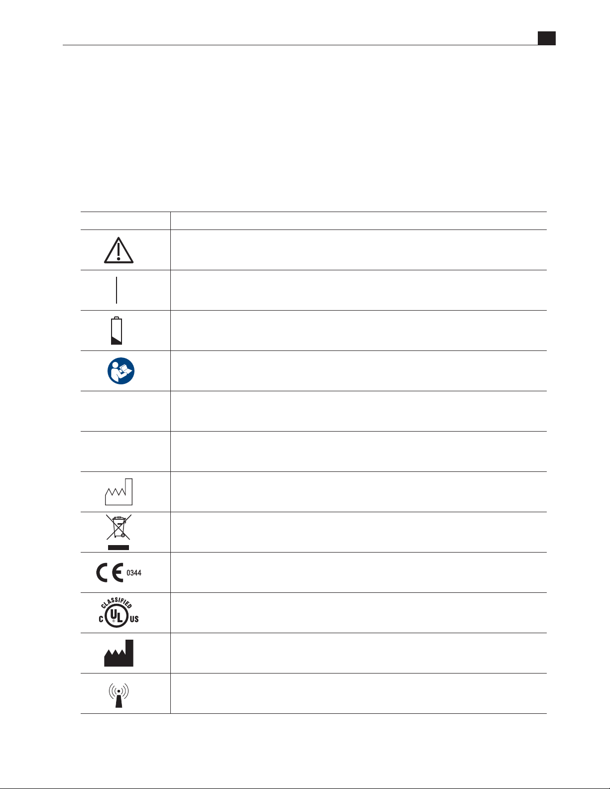
7. Symbols
Symbols
The following symbols are used on the product and/or packaging.
Symbol Description
EN
Tab le 7-1. Symbols
Attention: Consult accompanying documents
Power ON: To indicate connection to voltage mains
IPX1
IP68
Low battery
Follow instructions for use
Has passed IEC 60529, IPX1 water-ingress testing (Receiver)
Has passed IEC 60529, IP68 water-ingress testing (Transmitter)
Date of manufacture
Separate collection of waste at end of life as required by European Directives.
Dispose of in accordance with the applicable country regulation.
Axed in accordance with European Council Directive 93/42/EEC.
Classied by UL to IEC/UL 60601-1
Manufacturer
Non-ionizing electromagnetic radiation
RF Footswitch Operator’s Manual 7-1
Page 24

EN
This page intentionally left blank.
7-2 Symbols
Page 25

La pédale de contrôle RF
Manuel d’utilisation
34-109-1
FR
Page 26

FR
Copyright et marques
commerciales
Clause de non-
responsabilité
© 2019 Medtronic. Tous droits réservés. Medtronic, le logo Medtronic et Further, Together
sont des marques commerciales de Medtronic. Toutes les autres marques sont des marques
commerciales d’une société Medtronic.
Aucune partie de cette publication ne peut être reproduite, transmise, transcrite, enregistrée
dans des systèmes d’archivage ou traduite sous quelque forme que ce soit, ni d’aucune
manière: électronique, mécanique, magnétique, optique ou autre, sans l’autorisation
préalable par écrit de Medtronic Navigation, Inc. 180International Drive, Portsmouth,
NH03801, États-Unis d’Amérique.
Medtronic se réserve le droit de modier ses produits et ses services à tout moment pour y
incorporer les derniers développements technologiques. Ce manuel est susceptible d’être
modié sans préavis.
Selon la législation fédérale (États-Unis), ce dispositif est strictement réservé à la vente par un
médecin, ou sur ordonnance.
Numéros de téléphone du service clientèle:
US +1 800 595 9709
Intl. +1 720 890 3160
Page 27

Table des matières
1. Préface
Indications ................................................................................................................................................................................................ 1-1
Description du dispositif ............................................................................................................................................................ 1-1
Sécurité ...................................................................................................................................................................................................... 1-1
Utilisation générale ...................................................................................................................................................................... 1-1
Dénition de termes ............................................................................................................................................................................. 1-2
Mises en garde et avertissements .................................................................................................................................................... 1-3
2. La pédale de contrôle RF
La pédale de contrôle RF .....................................................................................................................................................................2-1
Canaux/Codage ............................................................................................................................................................................. 2-1
3. Fonctionnement
La pédale de contrôle RF .....................................................................................................................................................................3-1
FR
4. Nettoyage et entretien
Transmetteur ........................................................................................................................................................................................... 4-1
Récepteur ..................................................................................................................................................................................................4-1
5. Caractéristiques techniques
La pédale de contrôle RF .....................................................................................................................................................................5-1
Générales ......................................................................................................................................................................................... 5-1
Dimensions et poids .................................................................................................................................................................... 5-1
Certication ..................................................................................................................................................................................... 5-2
Interférence électromagnétique ............................................................................................................................................. 5-2
6. Garantie expresse limitée et clauses de non-responsabilité
Garantie expresse limitée ...................................................................................................................................................................6-1
Exclusion de garanties implicites et des dommages consécutifs ........................................................................................6-1
7. Symboles
Symboles ...................................................................................................................................................................................................7-1
La pédale de contrôle RF Manuel d’utilisatio i
Page 28

FR
Liste des gures
Figure2-1. Générateur AEX™, La pédale de contrôle RF ........................................................................................................2-1
Figure2-2. Vue avant du récepteur ............................................................................................................................................... 2-2
Figure2-3. Vue arrière du récepteur ............................................................................................................................................. 2-3
Figure2-4. Transmetteur ................................................................................................................................................................... 2-3
Figure3-1. Récepteur sans l ........................................................................................................................................................... 3-1
Figure4-1. Remplacement des piles du transmetteur ........................................................................................................... 4-2
Tableau7-1. Symboles ........................................................................................................................................................................ 7-1
ii
Page 29

1. Préface
Indications
La pédale de contrôle RF est un accessoire indiqué dans l’utilisation d’un interrupteur à pédale permettant de
contrôler le générateur AEX™ (40-405-1).
Description du dispositif
La pédale de contrôle RF est un accessoire du générateur AEX™. Cette commande au pied permet de contrôler
le générateur AEX™ qui utilise un contact de fermeture (marche/arrêt) an d’activer les pièces à main
électrochirurgicales monopolaires et bipolaires jetables Medtronic. L’utilisation de la commande au pied sans
l en option, associé au récepteur sans l (connecté au générateur AEX™), fournit la puissance COAG/CUT
nécessaire aux pièces à main monopolaires et bipolaires Medtronic.
FR
Sécurité
Les informations présentées dans cette section sont importantes pour la sécurité du patient et de l’utilisateur.
Elles permettent en outre d’améliorer la abilité du matériel. Cette section indique comment les termes Mise
en garde, Avertissement, Important et Remarque sont utilisés dans ce manuel.
Utilisation générale
Si la commande au pied est froide au toucher ou au-dessous de la température ambiante, laissez-la se
stabiliser avant de l’utiliser.
L’utilisation de matériel accessoire non conforme aux exigences de sécurité de cet équipement est susceptible
d’augmenter les risques liés à la sécurité.
Lors du choix de matériel accessoire, il convient de prendre en compte les points suivants:
• l’utilisation de l’accessoire à proximité du patient
• la preuve que la certication de sécurité de l’accessoire a bien été eectuée en accord avec la norme
nationale harmonisée CEI60601-1 et/ou CEI60601-1-2.
Périodiquement, chaque fois qu’il peut y avoir des doutes sur le bon état de marche de l’interrupteur, testez
toutes les fonctions.
La pédale de contrôle RF Manuel d’utilisatio 1-1
Page 30

FR
Dénition de termes
Quatre types de recommandations particulières sont utilisées dans ce manuel, à savoir: Mise en garde,
Avertissement, Important et Remarque. Les mises en garde et les avertissements contenus dans cette
section relative à la sécurité se rapportent à l’équipement en général et s’appliquent à tous les aspects de la
commande au pied. Veillez à lire consciencieusement les autres chapitres, car ils contiennent des mises en
garde et des avertissements liés à des fonctions spéciques de la commande au pied.
▲ MISE EN GARDE: Une mise en garde indique une situation dangereuse susceptible d’entraîner des
blessures ou la mort, si elle n’est pas corrigée ou évitée.
◆ AVERTISSEMENT: Un AVERTISSEMENT indique une situation potentiellement dangereuse
susceptible d’entraîner des blessures légères ou modérées si elle n’est pas évitée.
Lesavertissements sont également utilisés pour éviter d’endommager le matériel.
■ IMPORTANT: Le terme IMPORTANT permet de mettre l’accent sur un point particulier. Il s’agit d’un
point auquel vous devez prêter une attention particulière et qui n’apparaît pas de
manière évidente.
● REMARQUE: Une REMARQUE indique une information particulière à laquelle vous devez
porterattention.
1-2 Sécurité La pédale de contrôle RF Manuel d’utilisatio 1-31-2 Préface
Page 31

Mises en garde et avertissements
Les mises en garde et les avertissements présentés dans ce manuel doivent être lus, compris et respectés à des
ns de sécurité.
▲ Mise en garde relative aux renversements accidentels de liquides: si des liquides sont renversés par
accident sur le récepteur, interrompez le fonctionnement de ce dernier et vériez s’il n’a pas été endommagé.
▲ Mise en garde relative au risque de choc électrique: pour réduire le risque de choc électrique,
neretirez aucune protection. Conez la réparation à du personnel qualié.
▲ Mise en garde relative au risque d’explosion: n’utilisez pas cet équipement en présence
d’anesthésiques inammables.
▲ Mise en garde relative à la connexion à l’équipement: les commandes au pied doivent être
branchées à d’autres appareils. Veillez à consulter les spécications du fabricant pour garantir la sécurité
dufonctionnement.
FR
◆ Avertissement relatif à la maintenance annuelle: an de garantir la sécurité et le bon fonctionnement
de la commande, il est recommandé de vérier chaque année l’état et la sécurité électrique de la commande.
◆ Avertissement relatif aux tests quotidiens: il est essentiel de vérier la commande au pied chaque jour
ou avant toute utilisation.
◆ Avertissements relatifs au fonctionnement
• Le système de pédale de contrôle sans l fonctionne dans la plage de fréquences de 2,405 à 2,408 GHz. La
commande doit être testée pour garantir sa compatibilité avec tout appareil auquel elle est connectée ou
tout environnement dans lequel elle fonctionne.
• Signalez tous les problèmes que vous pouvez rencontrer avec la commande au pied. Si la commande
au pied ne fonctionne pas correctement, contactez le service clients pour demander une réparation.
Lacommande au pied ne doit pas être utilisée si elle ne fonctionne pas correctement.
Page 32

FR
Page intentionnellement laissée vierge.
1-4 Préface
Page 33

2. La pédale de contrôle RF
La pédale de contrôle RF
La pédale de contrôle RF fait partie des éléments du système de chirurgie (Medtronic/AEX™).
Le générateur fournit une énergie de radiofréquence (RF) aux pièces à main électrochirurgicales jetables.
Figure2-1. Générateur AEX™, La pédale de contrôle RF
FR
Générateur AEX™
La pédale de contrôle RF
Canaux/Codage
La pédale de contrôle à radiofréquence est dotée de quinze capacités de canal distinctes. Cela permet
d’utiliser simultanément plusieurs canaux dans la même zone. Le canal est identié dans le numéro de série
des unités. Voir l’exemple ci-dessous. Le canal apparaît également sur le libellé en haut des unités.
XXXXXXXX T001
En plus des quinze canaux, chaque fabricant possède son propre chirement de code. Ainsi, diérents
fabricants dotés du même marquage de canal peuvent être utilisés simultanément dans la même zone, sans
interférence. Le code du fabricant est intégré au numéro du modèle, comme indiqué ci-dessous. Il apparaît
également sur le libellé en haut des unités.
La lettre désigne le transmetteur ou le récepteur
SP-9970214-XXX XXXXXX
Ces trois chires correspondent au code du fabricant.
Le dernier chire désigne le canal
ExempleA:
LIBELLÉ DE L’UNITÉ: les deux ou trois premiers chires indiquent le code du fabricant; le dernier chire
correspond au canal.
La pédale de contrôle RF Manuel d’utilisatio 2-1
XXX
Page 34

FR
Vue avant du récepteur
Figure2-2. Vue avant du récepteur
A B C
Nom Description
A Indicateur de mise
sous tension
B Indicateurs de
fonctionnement des
commandes 1-5
C Indicateur de
faiblesse des piles
L’indicateur de mise sous tension clignote en vert pour indiquer que l’unité est
sous tension.
Le voyant est allumé lorsque la/les commande(s) fonctionne(nt).
Le voyant rouge clignote lorsque les piles approchent de leur n de vie. Levoyant
clignote durant 3 à 4heures. Lorsque le voyant s’allume en permanence, il
reste 3 à 4heures de durée de vie des piles. Les piles doivent cependant être
immédiatement remplacées.
2-2 La pédale de contrôle RF
Page 35

Vue arrière du récepteur
Description
FR
Figure2-3. Vue arrière du récepteur
J5 Connecteur de sortie: permet de raccorder le câble d’interface au générateur Medtronic/AEX™.
Transmetteur
Figure2-4. Transmetteur
A
Description
A Commandes principales
Fonction simple ou double
La pédale de contrôle RF Manuel d’utilisatio 2-3
Page 36

FR
Page intentionnellement laissée vierge.
2-4 La pédale de contrôle RF
Page 37

3. Fonctionnement
La pédale de contrôle RF
● REMARQUE: la commande au pied sans l est uniquement compatible avec des pièces à main activées.
1. Branchez le récepteur sans l dans le connecteur de la commande au pied situé à l’arrière du générateur
Medtronic/AEX™ en utilisant le câble d’interface adéquat. Lorsqu’une commande au pied est utilisée, la
puissance RF est fournie via la pièce à main.
2. Allumez le générateur Medtronic/AEX™ et vériez que le voyant d’alimentation du récepteur sans l est
vert, ce qui indique que le récepteur est sous tension.
Figure3-1. Récepteur sans l
FR
Voyant DEL
▲ MISE EN GARDE: assurez-vous que la commande au pied n’est pas enfoncée par mégarde, an d’empêcher
toute activation involontaire du dispositif. Placez la commande au pied dans un emplacement nécessitant
une action délibérée pour activer l’unité.
▲ MISE EN GARDE: Seul le chirurgien principal utilisant la pièce à main est habilité à utiliser la commande au
pied. Une activation involontaire peut survenir si la commande au pied est activée par un autre utilisateur,
risquant alors de blesser le patient ou l’utilisateur.
d’alimentation
La pédale de contrôle RF Manuel d’utilisatio 3-1
Page 38

FR
Page intentionnellement laissée vierge.
3-2 Fonctionnement
Page 39

4. Nettoyage et entretien
Pour le nettoyage, il convient de suivre les instructions ci-dessous.
◆ AVERTISSEMENTS:
• ABRASION: n’utilisez pas de chion abrasif, d’objets coupants ou de nettoyants abrasifs.
• DÉCONNEXION: débranchez les câbles d’interconnexion du récepteur.
• IMMERSION: n’immergez pas le récepteur, les câbles ou les connecteurs dans de l’eau.
Transmetteur
Le transmetteur répond à la norme IP68 et peut être totalement immergé de manière brève.
FR
Humectez un chion non abrasif à l’aide de l’un des produits suivants, puis essorez-le jusqu’à ce qu’il soit
légèrement humide et frottez délicatement la partie à nettoyer.
• Alcool isopropylique
• Savon et eau
• Cidex
• Hypochlorite de sodium à 5,25% (eau de javel), dilution10:1
Récepteur
◆ AVERTISSEMENT: le récepteur répond à la norme IPX1 et ne peut pas être immergé.
Humectez un chion non abrasif à l’aide de l’un des produits suivants, puis essorez-le jusqu’à ce qu’il soit
légèrement humide et frottez délicatement la partie à nettoyer.
• Alcool isopropylique
• Savon et eau
• Cidex
• Hypochlorite de sodium à 5,25% (eau de javel), dilution10:1
Essuyez tout liquide présent sur la surface du récepteur.
La pédale de contrôle RF Manuel d’utilisatio 4-1
Page 40

FR
Remplacement des piles
Figure4-1. Remplacement des piles du transmetteur
2LANGUETTES DE SÛRETÉ
COUVERCLE DES PILES
VIS À TÊTE FENDUE
FIXATION EN1/4 DE TOUR
JOINT TORIQUE
ZONE ENCASTRÉE POUR LE RETRAIT
DU COUVERCLE (FORCER QUELQUE PEU
AVEC UN TOURNEVIS À TÊTE PLATE
POUR RETIRER LE COUVERCLE)
3PILES AA
INDICATEUR DE POLARITÉ DES 3PILES
SUR LA FACE ARRIÈRE DU SUPPORT
Remplacez les piles du transmetteur par des piles alcalines AA de haute qualité comme indiqué ci-dessus.
◆ AVERTISSEMENTS:
• Ne mélangez jamais des piles de marques diérentes.
• Ne mélangez jamais anciennes et nouvelles piles.
• Lors du remplacement des piles, prenez garde à ne pas endommager le joint torique du couvercle des piles.
• Le joint torique doit être remplacé dès qu’il est endommagé ou dès qu’il y a un doute sur son état.
• Medtronic Navigation, Inc. recommande de remplacer le joint au minimum après trois remplacements
despiles. Lorsque vous remplacez le joint, lubriez-le à l’aide de vaseline.
• Fuite des piles: si le transmetteur n’est pas utilisé durant une période prolongée, retirez les piles an de
prévenir tout dommage lié à une possible fuite des piles.
• Élimination des piles usagées: respectez les recommandations du fabricant des piles ou la politique de
votre hôpital pour l’élimination des piles usagées.
4-2 Nettoyage et entretien
Page 41

5. Caractéristiques techniques
La pédale de contrôle RF
Toutes les caractéristiques techniques sont susceptibles d’être modiées sans préavis.
Générales
FR
Portée:
Fonctions de la commande:
Latence:
Consommation d’électricité
(transmetteur):
Exigences en matière
d’alimentation (récepteur):
Sortie du récepteur:
Communication :
Fréquence :
Chiffrement :
Transmetteur:
Récepteur:
Dimensions et poids
habituellement 9,14mètres (30pieds)
un maximum de2
habituellement 100millisecondes
2uA en veille
6VCD à 200mA
relais SPST, contacts 0,5A
Conforme à la norme IEEE802.15.4
2,4 GHz
Aucun - Seules les données du capteur sont transférées
EN60529 – Degré de protection IP68
EN 60529 – Degré de protection IPX1
Transmetteur
Largeur:
Longueur:
Hauteur:
Poids:
35,5cm (14,0po)
25,4cm (10,0po)
6,68cm (2,63po)
2,49kg (5,5lb) avec les piles
Récepteur
Largeur:
Longueur:
Hauteur:
Poids:
12,7cm (5,0po)
8,89cm (3,5po)
5,72cm (2,2po)
0,204kg (0,45lb)
La pédale de contrôle RF Manuel d’utilisatio 5-1
Page 42

FR
Certication
CEI/UL60601-1
CAN/CSA C22.2 No60601-1
Classé comme équipement électrique médical dans le cadre de
la norme CEI/UL60601-1 par Underwriters Laboratories, Inc. en
fonction des risques mécaniques et des risques liés aux incendies
et aux chocs.
Classé en fonction des risques mécaniques, des risques liés aux
chocs et aux incendies, et de tout autre risque mentionné.
Interférence électromagnétique
Cet appareil a été testé et reconnu conforme aux limites prescrites par la norme EN 60601-1-2 (2002) de la
directive 93/42/CEE relative aux dispositifs médicaux. Ces limites sont destinées à assurer une protection
raisonnable contre les interférences néfastes dans une installation médicale classique.
Toutefois, compte tenu de la prolifération des équipements à transmission par ondes radioélectriques et des
autres sources de bruit électrique dans les environnements médicaux et privés, il est possible qu’un niveau
élevé d’interférences de ce type, lié à la proximité ou à la force d’une source, nuise au bon fonctionnement
decet appareil.
Cet équipement génère, utilise et peut émettre des ondes radioélectriques. S’il n’est pas installé et utilisé
conformément à ces instructions, il peut provoquer des interférences et nuire au bon fonctionnement
d’autres appareils situés à proximité. Toute perturbation ou interférence peut être mise en évidence par
un fonctionnement erratique ou incorrect. Si un tel cas se présente, il convient d’identier la source de
dysfonctionnement sur le site et de prendre les mesures nécessaires pour l’éliminer.
Il est conseillé à l’utilisateur de corriger les interférences à l’aide de l’une des actions suivantes:
• Éteindre puis rallumer les appareils à proximité pour isoler celui d’où émane le problème.
• Réorienter ou déplacer l’autre appareil de réception.
• Augmenter l’espace qui sépare le matériel à l’origine des interférences de cet équipement.
• Si vous avez besoin d’assistance, contactez un spécialiste de Medtronic Navigation, Inc.
5-2 Caractéristiques techniques
Page 43

6. Garantie expresse limitée et
clauses de non-responsabilités
Garantie expresse limitée
Pendant un (1) an à compter de sa date d’expédition depuis Medtronic Navigation, Inc., si un pédale
de contrôle RFs’avère, à la satisfaction de Medtronic Navigation, Inc. inutilisable dans des conditions
normales et correctes conformément aux instructions applicables, Medtronic Navigation, Inc. réparera
ou remplacera le dispositif, à sa seule discrétion, à condition qu’il lui soit retourné, fret payé d’avance,
conformément à toutes les instructions de renvoi, de conditionnement et d’expédition. Un dispositif
réparé ou remplacé dans le cadre de cette garantie restera couvert pendant le reste de la période de
garantie initiale.
Exclusion de garanties implicites et des dommages consécutifs
FR
MEDTRONIC NAVIGATION, INC. N’ACCORDE AUCUNE AUTRE GARANTIE RELATIVE
AU DISPOSITIF ET DÉCLINE EXPLICITEMENT TOUTE AUTRE GARANTIE, EXPRESSE OU
IMPLICITE, DE QUALITÉ MARCHANDE, D’ADÉQUATION À UNE UTILISATION PARTICULIÈRE
OU AUTRE GARANTIE QUELCONQUE. MEDTRONIC NAVIGATION, INC. DÉCLINE DANS TOUS
LES CAS TOUTE RESPONSABILITÉ POUR DES DOMMAGES CONSÉCUTIFS. LA GARANTIE
CIDESSUS EST CONSIDÉRÉE COMME NULLE DANS LE CAS D’UN DISPOSITIF MODIFIÉ
OU RÉPARÉ PAR QUELQU’UN D’AUTRE QUE MEDTRONIC NAVIGATION, INC. OU L’UN DE
SES REPRÉSENTANTS AUTORISÉS, INCORRECTEMENT INSTALLÉ, UTILISÉ, ENTRETENU
OU STOCKÉ, OU SOUMIS À DES ABUS, MAUVAISES UTILISATIONS, NÉGLIGENCES OU
ACCIDENTS. MEDTRONIC NAVIGATION, INC. N’EST PAS RESPONSABLE DES DOMMAGES NI
DE TOUTE PERTE SURVENANT PENDANT LE RETOUR.
La pédale de contrôle RF Manuel d’utilisatio 6-1
Page 44

FR
Page intentionnellement laissée vierge.
6-2 Garantie expresse limitée et clauses de non-responsabilités
Page 45

7. Symboles
Symboles
Les symboles suivants gurent sur le produit et/ou l’emballage.
Symbole Description
Attention: consulter la documentation accompagnant le produit
Sous tension: indique la connexion au courant secteur
Pile déchargée
FR
Tableau7-1. Symboles
IPX1
IP68
Respecter les instructions d’utilisation
A réussi le test d’inltration d’eau CEI60529, IPX1 (récepteur)
A réussi le test d’inltration d’eau CEI60529, IP68 (transmetteur)
Date de fabrication
Collecte séparée des déchets en n de vie conformément aux directives européennes.
Mettre au rebut conformément à la législation applicable dans le pays.
Apposé conformément à la directive 93/42/CEE du Conseil européen
Classé par UL dans le cadre de la norme CEI/UL60601-1
Fabricant
Rayonnement électromagnétique non ionisant
La pédale de contrôle RF Manuel d’utilisatio 7-1
Page 46

FR
Page intentionnellement laissée vierge.
7-2 Symboles
Page 47

Comando a pedale RF
Manuale dell'operatore
34-109-1
IT
Page 48

IT
Copyright e marchi
commerciali
Dichiarazione di non
responsabilità
© 2019 Medtronic. Tutti i diritti riservati. Medtronic, il logo Medtronic e Further, Together
sono marchi commerciali di Medtronic. Tutti gli altri marchi sono marchi commerciali di una
società Medtronic.
Nessuna parte di questa pubblicazione può essere riprodotta, trasmessa, trascritta,
archiviata in sistemi di recupero o convertita in qualsiasi forma o con qualsiasi mezzo,
elettronico, meccanico, magnetico, ottico o altro, senza previa autorizzazione scritta di
Medtronic Navigation, Inc. 826 Coal Creek Circle, Louisville, CO 80027, Stati Uniti d'America.
Medtronic si riserva il diritto di modicare i propri prodotti e servizi in qualsiasi momento
per includervi i più recenti sviluppi tecnologici. Questa guida è soggetta a modiche
senza preavviso.
La legge federale statunitense limita la vendita di questo dispositivo ai medici o dietro
prescrizione medica.
Numeri di telefono dell'assistenza clienti:
US +1 800 595 9709
Intl. +1 720 890 3160
Page 49

Sommario
1. Prefazione
Indicazioni per l'uso .............................................................................................................................................................................. 1-1
Descrizione del dispositivo ........................................................................................................................................................ 1-1
Sicurezza ................................................................................................................................................................................................... 1-1
Uso generale ................................................................................................................................................................................... 1-1
Denizioni della terminologia ........................................................................................................................................................... 1-2
Avvertenze e Precauzioni ....................................................................................................................................................................1-3
2. Comando a pedale RF
Comando a pedale RF .......................................................................................................................................................................... 2-1
Canale/codica .............................................................................................................................................................................. 2-1
3. Funzionamento
Comando a pedale RF .......................................................................................................................................................................... 3-1
IT
4. Pulizia e manutenzione
Trasmettitore ........................................................................................................................................................................................... 4-1
Ricevitore .................................................................................................................................................................................................. 4-1
5. Speciche tecniche
Comando a pedale RF .......................................................................................................................................................................... 5-1
Generali ............................................................................................................................................................................................. 5-1
Dimensioni e peso ........................................................................................................................................................................ 5-1
Certicazione .................................................................................................................................................................................. 5-2
Interferenze elettromagnetiche...............................................................................................................................................5-2
6. Garanzia espressa limitata e dichiarazioni di non responsabilità
Garanzia espressa limitata .................................................................................................................................................................. 6-1
Dichiarazione di non responsabilità per le garanzie implicite e per i danni indiretti ........................................................6-1
7. Simboli
Simboli ....................................................................................................................................................................................................... 7-1
Comando a pedale RF Manuale dell’operatore i
Page 50

IT
Elenco delle gure
Figura 2-1. Generatore AEX™, Comando a pedale RF ..............................................................................................................2-1
Figura 2-2. Ricevitore Vista anteriore .............................................................................................................................................2-2
Figura 2-3. Ricevitore Vista posteriore ..........................................................................................................................................2-3
Figura 2-4. Trasmettitore ...................................................................................................................................................................2-3
Figura 3-1. Ricevitore wireless .........................................................................................................................................................3-1
Figura 4-1. Sostituzione batteria trasmettitore ......................................................................................................................... 4-2
Tabella 7-1. Simboli .............................................................................................................................................................................. 7-1
ii
Page 51

1. Prefazione
Indicazioni per l'uso
Comando a pedale RF è un accessorio il cui uso è indicato per il controllo a pedale del Generatore AEX™
(401-405-1).
Descrizione del dispositivo
Comando a pedale RF è un accessorio del Generatore AEX™. Il pedale permette di controllare il Generatore
AEX™, che utilizza un interruttore (on/o) di attivazione dei manipoli elettrochirurgici monouso monopolari
e bipolari Medtronic. L'uso del pedale wireless opzionale, in associazione al ricevitore wireless (connesso al
Generatore AEX™) ore ai manipoli monopolari e bipolari Medtronic la funzione CUT & COAG.
IT
Sicurezza
Le informazioni presentate in questa sezione sono importanti per la sicurezza del paziente e dell'operatore,
eservono inoltre a migliorare l'adabilità del prodotto. Questa sezione descrive in che modo vengono usati
itermini Avvertenza, Attenzione, Importante e Nota in tutto il manuale.
Uso generale
Se il Comando a pedale è freddo al tatto o al di sotto della temperatura ambiente, prima dell'uso attendere
lastabilizzazione della temperatura.
L'uso di accessori non conformi ai requisiti di sicurezza equivalenti a a quelli di questo apparecchio possono
causare una riduzione del livello di sicurezza del sistema risultante.
Le considerazioni relative alla scelta comprenderanno:
• uso dell'accessorio in prossimità del paziente
• prova che la certicazione di sicurezza dell'accessorio è stata eettuata conformemente all'appropriata
normativa nazionale armonizzata con le direttive IEC 60601-1 e/o IEC 60601-1-2.
Testare tutte le funzioni periodicamente e ogni volta che l'integrità del Comando a pedale è in dubbio.
Comando a pedale RF Manuale dell’operatore 1-1
Page 52

IT
Denizioni della terminologia
In tutto il manuale vengono usati quattro tipi di avvertenze speciali. Esse sono: Avvertenza, Attenzione,
Importante e Nota. Le indicazioni Avvertenza e Attenzione in questa sezione sulla sicurezza si riferiscono
all'apparecchio in generale, e si applicano a tutti gli aspetti del Comando a pedale. Assicurarsi di leggere gli
altri capitoli, perché vi sono altre indicazioni di Avvertenza e Attenzione relative a caratteristiche speciche
delComando a pedale.
▲ AVVERTENZA: un'avvertenza indica una condizione di pericolo che potrebbe provocare una lesione o la
morte se non viene corretta o evitata.
◆ ATTENZIONE: ATTENZIONE indica una condizione di potenziale pericolo che, se non evitata,
potrebbe causare una lesione lieve o moderata. L'indicazione ATTENZIONE viene usata
anche per evitare un danno all'apparecchio.
■ IMPORTANTE: La nota IMPORTANTE indica una nota importante. Si tratta di una situazione cui si
deve prestare particolarmente attenzione, e che non è immediatamente evidente.
● NOTA: Una NOTA indica un'informazione particolare, qualcosa su cui concentrare
lapropriaattenzione.
1-2 Prefazione
Page 53

Avvertenze e Precauzioni
Per motivi di sicurezza occorre leggere, comprendere e seguire le avvertenze e le precauzioni presentate
inquesto manuale.
▲ Avvertenze per gli sversamenti accidentali: In caso di sversamento accidentale di uidi sul ricevitore,
mettere il ricevitore temporaneamente fuori servizio e controllare che non abbia subito eventuali danni.
▲ Avvertenza Pericolo di folgorazione. Per ridurre il rischio di folgorazione, non rimuovere nessun
coperchio. Rivolgersi all'assistenza per richiedere l'intervento di personale qualicato.
▲ Avvertenza Pericolo di esplosione: Non usare questo apparecchio in presenza di anestetici inammabili.
▲ Avvertenza collegamento ad altri dispositivi: I Comandi a pedale devono essere collegati ad altri dis-
positivi. Per mantenere un funzionamento sicuro del prodotto, assicurarsi di consultare le speciche delfabbricante.
IT
◆ Attenzione revisioni annuali: Per la continua sicurezza e il corretto funzionamento del Comando apedale,
si raccomanda di vericarne annualmente la funzionalità e la sicurezza elettrica.
◆ Attenzione test giornalieri: È essenziale che il Comando a pedale sia ispezionato ogni giorno o prima dell'uso.
◆ Attenzione prestazioni:
• La gamma di frequenza di funzionamento del sistema wireless con comando a pedale è compresa tra 2,405 e
2,408 GHz. Il sistema deve essere testato per vericarne la compatibilità con qualsiasi altro dispositivo ad esso
collegato o all’ambiente di lavoro.
• Riferire qualsiasi problema si presenti durante l'uso del Comando a pedale. Qualora il Comando a pedale
non dovesse funzionare correttamente, contattare il servizio clienti. In caso di malfunzionamento,
ilComando a pedale non deve essere usato.
Comando a pedale RF Manuale dell’operatore 1-3
Page 54

IT
Questa pagina è lasciata intenzionalmente in bianco.
1-4 Prefazione
Page 55

2. Il Comando a pedale RF
Il Comando a pedale RF
La pédale de contrôle RF è un componente del Sistema Chirurgico (Medtronic/AEX™). IlGeneratore fornisce
energia in radiofrequenza (RF) a manipoli elettrochirurgici monouso.
Figura 2-1. Generatore AEX™, Comando a pedale RF
IT
Générateur AEX™
Comando a pedale RF
Canale/codica
La frequenza radio del comando a pedale dispone di quindici canali distinti. Questo permette di usare più
canali simultaneamente nella stessa area. Il canale viene identicato nel numero di serie delle unità. Vedere
l’esempio di seguito. Il canale è indicato anche su un’etichetta sulla parte superiore delle unità.
XXXXXXXX T001
Oltre ai quindici canali, ogni produttore dispone di una sua propria cifratura a codice. Questo assicura la
possibilità di usare simultaneamente nella stessa area prodotti di fabbricanti diversi con gli stessi canali senza
pericolo di interferenze. Il codice del fabbricante è incluso nel codice del modello, come mostrato più sotto.
Esso è indicato anche su un'etichetta sulla parte superiore delle unità.
La lettera indica trasmettitore o ricevitore
SP-9970214-XXX XXXXXX
Queste tre cifre indicano il codice del fabbricante.
L'ultima cifra indica il canale
Esempio A:
ETICHETTA DELL'UNITÀ: Le prime due o tre cifre indicano il codice del fabbricante; l'ultima cifra indica il canale.
Comando a pedale RF Manuale dell’operatore 2-1
XXX
Page 56

IT
Ricevitore, vista anteriore
Figura 2-2. Ricevitore, vista anteriore
A B C
Nome Descrizione
A Indicatore di
accensione
B Indicatori
funzionamento
Comando 1-5
C Indicatore batteria
bassa del Comando
apedale
L'indicatore di accensione diventa verde per indicare che l'unità è accesa
I LED si accendono quando il Comando/i sono in funzione.
Il LED rosso lampeggia quando le batterie sono prossime all'esaurimento. Il
LED lampeggia per 3-4 ore. Quando la luce del LED è costante, rimangono circa
3-4ore di batteria. Tuttavia, le batterie devono essere sostituite immediatamente.
2-2 Il Comando a pedale RF
Page 57

Ricevitore, vista posteriore
Descrizione
IT
Figura 2-3. Ricevitore, vista posteriore
J5 Connettore di uscita: Per la connessione del cavo di interfaccia al Generatore Medtronic/AEX™.
Trasmettitore
Figura 2-4. Trasmettitore
A
Descrizione
A Interruttori principali
Funzione singola o doppia
Comando a pedale RF Manuale dell’operatore 2-3
Page 58

IT
Questa pagina è lasciata intenzionalmente in bianco.
2-4 Il Comando a pedale RF
Page 59

3. Funzionamento
Il Comando a pedale RF
● NOTA: Il Comando a pedale wireless è compatibile solo con i manipoli abilitati.
1. Collegare il ricevitore wireless nel connettore del Comando a pedale sul retro del Generatore Medtronic/
AEX™ usando il cavo di interfaccia adatto. Mentre si usa un comando a pedale, l'energia RF verrà erogata
attraverso il manipolo.
2. Accendere il Generatore Medtronic/AEX™ e vericare che il LED di accensione del ricevitore wireless sia
verde, a indicare che il ricevitore è acceso.
Figura 3-1. Ricevitore wireless
IT
LED di
▲ AVVERTENZA: Vericare che il comando a pedale non sia inavvertitamente premuto, onde evitare che
il dispositivo venga attivato accidentalmente. Porre il Comando a pedale in una posizione che richieda
un'azione deliberata per attivare l'unità.
▲ AVVERTENZA: Il Comando a pedale deve essere attivato solo dal chirurgo principale che utilizza
il manipolo. Se il Comando a pedale viene utilizzato da un operatore diverso potrebbe vericarsi
un'attivazione accidentale, e questo potrebbe causare una lesione al paziente o all'utilizzatore.
accensione
Comando a pedale RF Manuale dell’operatore 3-1
Page 60

IT
Questa pagina è lasciata intenzionalmente in bianco.
3-2 Funzionamento
Page 61

4. Pulizia e manutenzione
Vengono fornite le seguenti istruzioni di pulizia.
◆ ATTENZIONE:
• ABRASIONE: Non usare panni abrasivi, oggetti taglienti o detergenti abrasivi.
• DISCONNESSIONE: Staccare i cavi di connessione dal ricevitore.
• IMMERSIONE: Non immergere il ricevitore, i cavi o i connettori nell'acqua corrente.
Trasmettitore
IT
Il trasmettitore è classicato IP68 e può essere brevemente immerso completamente.
Inumidire un panno non abrasivo con uno dei prodotti che seguono; quindi strizzarlo no a che non sarà
solo leggermente umido e stronare delicatamente l'area sporca no a che non sarà pulita.
• Alcool isopropilico
• Acqua e sapone
• Cidex
• Ipoclorito di sodio al 5,25% (candeggina) diluito 10:1
Ricevitore
◆ ATTENZIONE: Il ricevitore è classicato IPX1 e non può essere immerso in acqua.
Inumidire un panno non abrasivo con uno dei prodotti che seguono; quindi strizzarlo no a che non sarà
solo leggermente umido e stronare delicatamente l'area sporca no a che non sarà pulita.
• Alcool isopropilico
• Acqua e sapone
• Cidex
• Candeggina Ipoclorito di sodio al 5,25% (candeggina) diluito 10:1
Asciugare qualsiasi tipo di uido dalla supercie del ricevitore.
Comando a pedale RF Manuale dell’operatore 4-1
Page 62

IT
Sostituzione della batteria
Figura 4-1. Sostituzione della batteria del trasmettitore
2X LINGUETTE DI BLOCCO
COPERCHIO VANO BATTERIE
VITE A TAGLIO
FISSAGGIO A 1/4 DI GIRO
ANELLO DI TENUTA
AREA INCASSATA PER LA
RIMOZIONE DEL COPERCHIO
(FARLEVA DELICATAMENTE CON
UN CACCIAVITE A TESTA PIATTA PER
RIMUOVERE IL COPERCHIO)
3X BATTERIE “AA”
3X INDICATORE DI POLARITÀ DELLE BATTERIE
SUL LATO INFERIORE DEL SUPPORTO
Sostituire le batterie nel trasmettitore con pile alcaline “AA” di alta qualità, come indicato.
◆ ATTENZIONE:
• Quando si sostituiscono le batterie, non mescolare mai batterie di produttori diversi.
• Non mescolare mai batterie vecchie e nuove.
• Durante la sostituzione delle batterie prestare attenzione a non danneggiare l'anello di tenuta sul coperchio
del vano batterie.
• Sostituire l'anello di tenuta se lo si ritiene danneggiato o se la sua integrità è dubbia.
• Medtronic Navigation, Inc. raccomanda di sostituire l'anello di tenuta almeno a ogni terza sostituzione delle
batterie. Quando si sostituisce l'anello di tenuta, lubricarlo con vaselina.
• Perdita dalle batterie: Se il trasmettitore non viene usato per un lungo periodo di tempo, rimuovere
lebatterie per impedire un danno causato da una possibile perdita dalle batterie.
• Smaltimento delle batterie: Per lo smaltimento delle batterie usate seguire le raccomandazioni
delfabbricante o le normative di smaltimento delle batterie usate dell'ospedale.
4-2 Pulizia e manutenzione
Page 63

5. Speciche tecniche
Il Comando a pedale RF
Tutte le speciche tecniche sono soggette a variazioni senza preavviso.
Generali
IT
Intervallo:
Funzioni del Comando:
Latenza:
Consumo (trasmettitore):
Alimentazione (ricevitore):
Output ricevitore:
Comunicazione:
Frequenza:
Cifratura:
Trasmettitore:
Ricevitore:
Dimensioni e peso
Trasmettitore
Tipicamente 30 piedi (9,14 m)
Massimo 2
Tipicamente 100 millisecondi
Stand-by 2ua
6VDC @ 200ma
Uscita a relé con contatto SPST 0,5 amp
Conforme allo standard IEEE802.15.4
2,4 GHz
Nessuna. Trasferimento dei soli dati del sensore
EN 60529 Grado di protezione IP68
EN 60529 Grado di protezione IPX1
Larghezza:
Lunghezza:
Altezza:
Peso:
Ricevitore
Larghezza:
Lunghezza:
Altezza:
Peso:
Comando a pedale RF Manuale dell’operatore 5-1
35,5 cm (14,0 pollici)
25,4 cm (10,0 pollici)
6,68 cm (2,63 pollici)
2,49 kg (5,5 libbre) con batterie
12,7 cm (5,0 pollici)
8,89 cm (3,5 pollici)
5,72 cm (2,2 pollici)
0,204 kg (0,45 libbre)
Page 64

IT
Certicazione
IEC/UL 60601-1
CAN/CSA C22.2 N. 60601-1
Classicato secondo la norma IEC/UL 60601-1 Apparecchiature
elettromedicali da Underwriter's Laboratories, Inc. relativamente
a incendi e pericoli di natura elettrica e meccanica.
Classicato unicamente in relazione a incendi e pericoli di natura
elettrica, meccanica e altri pericoli specici.
Interferenze elettromagnetiche
Questo dispositivo è stato testato ed è risultato conforme ai limiti per i dispositivi medici previsti dalla
normativa EN 60601-1-2 (2002), Direttiva per i Dispositivi Medici 93/42/CEE. Tali limiti sono ideati per fornire
una protezione ragionevole contro le interferenze nocive in una tipica installazione in ambiente medico.
Tuttavia, a causa della proliferazione di apparecchiature a radiofrequenza e di altre fonti di disturbi elettrici in
ambiente sia medico sia domiciliare è possibile che, a causa della stretta vicinanza o forza della fonte, alti livelli
di tali interferenze possano causare un disturbo alle prestazioni del dispositivo.
Questo apparecchio genera, utilizza e può irradiare energia in radiofrequenza e, se non viene installato e
utilizzato conformemente alle istruzioni, può produrre interferenze nocive che disturbano altri dispositivi nelle
vicinanze. I disturbi o le interferenze possono essere evidenziati da un funzionamento erratico o scorretto.
Intal caso, l'area d'uso deve essere accuratamente controllata in modo da determinare la fonte del disturbo,
che deve quindi essere eliminata.
L'utente è incoraggiato a cercare di correggere l'interferenza intraprendendo una delle misure che seguono:
• Spegnere e accendere i dispositivi nelle vicinanze per isolare l'apparecchio fonte di disturbo.
• Riorientare o riposizionare l'altro dispositivo di ricezione.
• Aumentare la distanza tra il dispositivo che interferisce e questo prodotto.
• In caso di necessità, contattare il proprio rappresentante Medtronic Navigation, Inc.
5-2 Specifiche tecniche
Page 65

6. Garanzia espressa limitata e dichiarazioni di
non responsabilità
Garanzia espressa limitata
Per un periodo di un (1) anno dalla data di spedizione da parte di Medtronic Navigation, Inc., se, a giudizio di
Medtronic Navigation, Inc., Il Comando a pedale RF dovesse essere ritenuto non funzionante per il normale
impiego in conformità con le relative istruzioni, Medtronic Navigation, Inc. s’impegna a riparare o sostituire il
prodotto, a sua esclusiva discrezione, purché questo venga restituito, con spedizione prepagata, seguendo
tutte le istruzioni per l’imballaggio e la spedizione di reso. Un prodotto riparato o sostituito in base alla
presente garanzia sarà garantito per il periodo residuo della garanzia originale.
Dichiarazione di non responsabilità per le garanzie implicite e per i
danni indiretti
IT
MEDTRONIC NAVIGATION, INC. NON OFFRE ALCUN ALTRA GARANZIA PER IL PRODOTTO E
NON RICONOSCE ASSOLUTAMENTE TUTTE LE ALTRE GARANZIE, ESPRESSE O IMPLICITE, COME
PURE DI COMMERCIABILITÀ E IDONEITÀ PER UNO SCOPO PARTICOLARE O QUALSIASI ALTRA
QUESTIONE. IN NESSUN CASO MEDTRONIC NAVIGATION, INC. SARÀ RESPONSABILE PER
QUALSIASI DANNO CONSEQUENZIALE. LA PRESENTE GARANZIA NON SI APPLICA A PRODOTTI
CHE SIANO STATI MODIFICATI O RIPARATI DA PERSONE DIVERSE DA MEDTRONIC NAVIGATION,
INC. O DA UN SUO RAPPRESENTANTE AUTORIZZATO, INSTALLATI, USATI O CONSERVATI IN
MODO SCORRETTO, O CHE ABBIANO SUBITO INTERVENTI DI MANUTENZIONE INADEGUATI,
O ANCORA ABUSI, USI IMPROPRI, NEGLIGENZE O INCIDENTI. MEDTRONIC NAVIGATION, INC.
NON È RESPONSABILE PER I DANNI O ALTRA PERDITA CHE DOVESSE VERIFICARSI DURANTE LA
SPEDIZIONE DI RESO.
Comando a pedale RF Manuale dell’operatore 6-1
Page 66

IT
Questa pagina è lasciata intenzionalmente in bianco.
6-2 Garanzia espressa limitata e dichiarazioni di non responsabilità
Page 67

7. Simboli
Simboli
I simboli che seguono vengono usati sul prodotto e/o sulla sua confezione.
Simbolo Descrizione
IT
Tab ella 7-1. Simboli
Attenzione: Consultare i documenti allegati.
Alimentazione accesa: Indica il collegamento alla tensione di rete
Batteria scarica
IPX1
IP68
Seguire le Istruzioni per l'uso
Ha superato il test di immersione in acqua IPX1, IEC 60529 (ricevitore).
Ha superato il test di immersione in acqua IP68, IEC 60529 (trasmettitore).
Data di produzione
Raccolta dierenziata dei riuti al termine del ciclo di vita come richiesto dalle direttive europee.
Smaltire in conformità alle dispositive nazionali in vigore.
Asso in conformità alla Direttiva del consiglio europeo 93/42/CEE.
Classicato UL IEC/UL 60601-1
Produttore
Radiazione elettromagnetica non ionizzante
Comando a pedale RF Manuale dell’operatore 7-1
Page 68

IT
Questa pagina è lasciata intenzionalmente in bianco.
7-2 Simboli
Page 69

Der RF-Fußschalter
Bedienungshandbuch
34-109-1
DE
Page 70

DE
Copyright
und Marken
Haftungsausschluss
© 2019 Medtronic. Alle Rechte vorbehalten. Medtronic, das Medtronic-Logo und
„Further, Together“ sind Marken von Medtronic. Alle anderen Marken sind Marken
eines Medtronic-Unternehmens.
Kein Teil dieser Veröentlichung darf ohne vorherige schriftliche Genehmigung durch
Medtronic Navigation, Inc. 826 Coal Creek Circle, Louisville, CO 80027, Vereinigte
Staaten von Amerika, auf elektronische, mechanische, magnetische, optische oder
sonstige Art und Weise reproduziert, übertragen, transkribiert, in Abfragesystemen
gespeichert oder übersetzt werden.
Medtronic behält sich das Recht vor, seine Produkte und Dienstleistungen jederzeit
zu ändern, um die aktuellsten technologischen Entwicklungen zu implementieren.
Dieses Handbuch kann jederzeit geändert werden.
Laut US-amerikanischem Bundesgesetz darf der Verkauf dieses Gerätes nur an Ärzte
oder in deren Auftrag erfolgen.
Kundendiensttelefonnummern:
US +1 800 595 9709
Intl. +1 720 890 3160
Page 71

Inhalt
1. Vorwort
Anwendungsgebiete ............................................................................................................................................................................ 1-1
Gerätebeschreibung .................................................................................................................................................................... 1-1
Sicherheit .................................................................................................................................................................................................. 1-1
Allgemeine Verwendung ............................................................................................................................................................1-1
Terminologische Denitionen ........................................................................................................................................................... 1-2
Warn- und Vorsichtshinweise ............................................................................................................................................................ 1-3
2. Der RF-Fußschalter
Der RF-Fußschalter ................................................................................................................................................................................ 2-1
Kanal/Codierung ........................................................................................................................................................................... 2-1
3. Betrieb
Der RF-Fußschalter ................................................................................................................................................................................ 3-1
DE
4. Reinigung und Wartung
Transmitter ............................................................................................................................................................................................... 4-1
Empfänger ................................................................................................................................................................................................ 4-1
5. Technische Daten
Der RF-Fußschalter ................................................................................................................................................................................ 5-1
Allgemein ......................................................................................................................................................................................... 5-1
Abmessungen und Gewicht ...................................................................................................................................................... 5-1
Zertizierung .................................................................................................................................................................................. 5-2
Elektromagnetische Störungen ............................................................................................................................................... 5-2
6. Eingeschränkte ausdrückliche Gewährleistung und Haftungsausschluss
Eingeschränkte ausdrückliche Gewährleistung ......................................................................................................................... 6-1
Haftungsausschluss für implizierte Garantien und Folgeschäden ...................................................................................... 6-1
7. Symbole
Symbole.....................................................................................................................................................................................................7-1
Der RF-Fußschalter – Bedienungshandbuch i
Page 72

DE
Abbildungsverzeichnis
Abbildung 2-1. AEX™ Generator, Der RF-Fußschalterr ............................................................................................................2-1
Abbildung 2-2. Frontansicht Empfänger .....................................................................................................................................2-2
Abbildung 2-3. Rückansicht Empfänger ......................................................................................................................................2-3
Abbildung 2-4. Transmitter ..............................................................................................................................................................2-3
Abbildung 3-1. Kabelloser Empfänger .........................................................................................................................................3-1
Abbildung 4-1. Batteriewechsel beim Transmitter ................................................................................................................. 4-2
Tabelle 7-1. Symbole ............................................................................................................................................................................ 7-1
ii
Page 73

1. Vorwort
Anwendungsgebiete
Der RF-Fußschalter ist ein Zubehörteil zur Eingangssteuerung des AEX™ Generators perFußschalter (40-405-1).
Gerätebeschreibung
Der RF-Fußschalter ist ein Zubehörteil für den AEX™ Generator. Der Fußschalter ermöglicht die
Eingangssteuerung zum AEX™ Generator, bei dem über einen Kontaktschalter (an/aus) monopolare und
bipolare elektrochirurgische Handgeräte von Medtronic zum Einmalgebrauch aktiviert werden. Durch die
Verwendung des optionalen kabellosen Fußschalters in Kombination mit dem kabellosen Empfänger (an
den AEX™ Generator angeschlossen) werden monopolare und bipolare Handgeräte von Medtronic mit auf
SCHNEIDEN UND KOAGULIEREN ausgelegter Stromzufuhr versorgt.
DE
Sicherheit
Die Informationen in diesem Abschnitt sind für die Sicherheit sowohl des Patienten als auch des Bedieners
wichtig und dienen außerdem zur Verbesserung der Zuverlässigkeit des Geräts. In diesem Abschnitt wird die
Verwendung der Begrie „Warnung“, „Vorsicht“, „Wichtig“ und „Anmerkung“ in diesem Handbuch beschrieben.
Allgemeine Verwendung
Wenn der Fußschalter sich kalt anfühlt oder unterhalb der Zimmertemperatur liegt, lassen Sie ihn vor der
Benutzung aufwärmen.
Die Verwendung von Zubehör, das nicht den Sicherheitsanforderungen dieses Geräts entspricht, kann das
Sicherheitsniveau des Systems verringern.
Bei der Entscheidung sollten folgende Faktoren in Betracht gezogen werden:
• Verwendung des Zubehörs in Patientennähe
• Nachweis, dass die Sicherheitszertizierung des Zubehörteils gemäß IEC 60601-1 und/oder IEC 60601-1-2
oder entsprechenden nationalen Standards vorgenommen wurde.
Testen Sie regelmäßig alle Funktionen, wenn die einwandfreie Funktion des Schalters nicht gesichert ist.
Der RF-Fußschalter – Bedienungshandbuch 1-1
Page 74

DE
Terminologische Denitionen
Vier Arten von speziellen Anmerkungen werden in diesem Handbuch verwendet. Sie lauten: Warnung, Vorsicht,
Wichtig und Hinweis. Die Warnungen und Vorsichtshinweise in diesem Sicherheitsabschnitt beziehen sich auf das
gesamte Gerät und gelten für alle Aspekte des Fußschalters. Lesen Sie auch die anderen Kapitel, da es zusätzliche
Warnungen und Vorsichtshinweise gibt, die sich auf bestimmte Funktionen des Fußschalters beziehen.
▲ WARNUNG: Eine Warnung deutet auf eine gefährliche Situation hin, die zu Verletzungen oder zum Tod
führen kann, wenn sie nicht behoben oder vermieden wird.
◆ VORSICHT: VORSICHT weist auf eine möglicherweise gefährliche Situation hin, die zu leichten
oder mittelschweren Verletzungen führen kann. Vorsichtshinweise werden auch zur
Vermeidung von Schäden an Geräten verwendet.
■ WICHTIG: Eine WICHTIG-Anmerkung ist ein hervorgehobener Hinweis. Er weist auf etwas hin,
worauf Sie besonders achten sollten und das nicht oensichtlich ist.
● ANMERKUNG: Eine ANMERKUNG weist auf eine bestimmte Information hin, die Sie beachten sollten.
1-2 Vorwort
Page 75

Warn- und Vorsichtshinweise
Die Warn- und Vorsichtshinweise in diesem Handbuch sollten aus Gründen der Sicherheit gelesen, verstanden
und befolgt werden.
▲ Warnung bei versehentlichem Verschütten: Wenn versehentlich Flüssigkeit auf den Empfänger ver-
schüttet wird, nehmen Sie ihn außer Betrieb und untersuchen Sie ihn nach Schäden.
▲ Warnung: Stromschlaggefahr. Zur Vermeidung von Stromschlägen keine Abdeckungen entfernen.
Wartung von qualiziertem Wartungspersonal durchführen lassen.
▲ Warnung: Explosionsgefahr: Dieses Gerät darf nicht in der Nähe brennbarer Anästhetika verwendet
werden.
▲ Warnung: Verbindung mit Geräten: Der Fußschalter muss mit einem anderen Gerät verbunden sein.
Weitere Hinweise zum sicheren Betrieb nden Sie in den Herstellerangaben.
DE
◆ Vorsicht: Jährliche Wartung: Um die Sicherheit und Funktion des Schalters dauerhaft zu
gewährleisten,wird eine jährliche Prüfung der Funktionalität und elektrischen Sicherheit empfohlen.
◆ Vorsicht: Tägliche Tests: Der Fußschalter sollte unbedingt täglich oder vor der Verwendung
inspiziertwerden.
◆ Vorsicht: Leistung:
• Der Frequenzbereich des drahtlosen Fußschaltersystems reicht von 2,405 bis 2,408 GHz. Zur
Sicherstellung der Kompatibilität mit dem verbundenen Gerät oder der Betriebsumgebung sollte ein
Test durchgeführt werden.
• Alle festgestellten Probleme mit dem Fußschalter sind zu melden. Wenn der Fußschalter nicht
ordnungsgemäß funktioniert, wenden Sie sich zur Reparatur an Ihren Servicepartner. Der Fußschalter
sollte nicht verwendet werden, wenn er nicht ordnungsgemäß funktioniert.
Der RF-Fußschalter – Bedienungshandbuch 1-3
Page 76

DE
Diese Seite absichtlich leer gelassen.
1-4 Vorwort
Page 77

2. Der RF-Fußschalter
Der RF-Fußschalter
Der RF-Fußschalter ist ein Bestandteil des (Medtronic/AEX™) Chirurgiesystems. Der Generator liefert die
Hochfrequenz-(HF-)Energie für elektrochirurgische Handgeräte für den einmaligenGebrauch.
Abbildung 2-1. AEX™ Generator, Der RF-Fußschalter
DE
AEX™ Generator
Der RF-Fußschalter
Kanal/Codierung
Der Radiofrequenz-Fußschalter kann auf fünfzehn verschiedenen Kanälen betrieben werden. Somit können
in einer Umgebung mehrere Kanäle gleichzeitig verwendet werden. Der Kanal ist in der Seriennummer der
Einheit angegeben. Siehe das folgende Beispiel. Der Kanal ist auch auf einem Etikett auf der Oberseite der
Einheit angegeben.
XXXXXXXX T001
Zusätzlich zu den fünfzehn Kanälen verwendet jeder Hersteller seinen eigenen Verschlüsselungscode. So
wird gewährleistet, dass Geräte verschiedener Hersteller, die auf demselben Kanal arbeiten, gleichzeitig in
der gleichen Umgebung verwendet werden können, ohne dass es zu Störungen kommt. Der Herstellercode
ist, wie unten gezeigt, in der Modellnummer enthalten. Er ist auch auf einem Etikett auf der Oberseite der
Einheitangegeben.
Buchstabe gibt Transmitter oder Empfänger an
SP-9970214-XXX XXXXXX
Diese drei Stellen sind der Herstellercode.
Letzte Stelle gibt Kanal an
Beispiel A :
EINHEITSETIKETT: Die ersten zwei oder drei Stellen sind der Herstellercode; die letzte Stelle gibt den Kanal an.
Der RF-Fußschalter – Bedienungshandbuch 2-1
XXX
Page 78

DE
Frontansicht Empfänger
Abbildung 2-2. Frontansicht Empfänger
A B C
Name Beschreibung
A Betriebsindikator Der Betriebsindikator leuchtet grün, wenn die Einheit angeschaltet ist
B Schalterfunktionsindikatoren
1–5
C Indikator: Fußschalterbatterie
schwach
LEDs leuchten, wenn der/die Schalter betätigt wird/werden.
Rote LED blinkt, wenn die Batterien fast leer sind. Die LED blinkt für 3–4 Stunden.
Wenn die LED durchgehend leuchtet, verbleiben 3–4 Stunden Batterielaufzeit.
Die Batterien sollten jedoch umgehend gewechselt werden.
2-2 Der RF-Fußschalter
Page 79

Rückansicht Empfänger
Beschreibung
DE
Abbildung 2-3. Rückansicht Empfänger
J5 Ausgangsbuchse: Zum Anschluss des Schnittstellenkabels zum Medtronic/AEX™ Generator.
Transmitter
Abbildung 2-4. Transmitter
A
Beschreibung
A Primärschalter
Einzel- oder Dualfunktion
Der RF-Fußschalter – Bedienungshandbuch 2-3
Page 80

DE
Diese Seite absichtlich leer gelassen.
2-4 Der RF-Fußschalter
Page 81

3. Betrieb
Der RF-Fußschalter
● ANMERKUNG: Der kabellose Fußschalter ist nur mit aktivierten Handstücken kompatibel.
1. Schließen Sie den kabellosen Empfänger mit dem passenden Kabel an die Fußschalterbuchse an der
Rückseite des Medtronic/AEX™ Generators an. Bei Betätigung des Fußschalters wird das Handgerät mit
HF-Leistung versorgt.
2. Schalten Sie den Medtronic/AEX™ Generator ein und vergewissern Sie sich, dass die Betriebs-LED grün
leuchtet und damit anzeigt, dass der Empfänger eingeschaltet ist.
Abbildung 3-1. Kabelloser Empfänger
DE
Betriebs-LED
▲ WARNUNG: Achten Sie darauf, dass der Fußschalter nicht versehentlich gedrückt wird, um eine
unbeabsichtigte Aktivierung des Geräts zu vermeiden. Platzieren Sie den Fußschalter so, dass die
Einheit nur durch bewusstes Betätigen des Schalters aktiviert werden kann.
▲ WARNUNG: Der Fußschalter sollte ausschließlich von dem Chirurgen betätigt werden, der auch das
Handstück verwendet. Wird der Fußschalter von einem anderen Benutzer betätigt, kann es zu einer
unbeabsichtigten Aktivierung kommen, wodurch der Patient oder der Chirurg verletzt werden kann.
Der RF-Fußschalter – Bedienungshandbuch 3-1
Page 82

DE
Diese Seite absichtlich leer gelassen.
3-2 Betrieb
Page 83

4. Reinigung und Wartung
Beachten Sie die folgenden Reinigungshinweise.
◆ VORSICHTSHINWEISE:
• ABRIEB: Verwenden Sie keine scheuernden Tücher, scharfe oder spitze Gegenstände oder scheuernde
Reinigungsmittel.
• TRENNUNG: Lösen Sie die Verbindungskabel vom Empfänger.
• EINTAUCHEN: Tauchen Sie den Empfänger, die Kabel und die Buchsen nicht in Wasser ein.
Transmitter
DE
Der Transmitter wurde in die Schutzklasse IP68 eingestuft und kann für kurze Zeit vollständig in Wasser
eingetaucht werden.
Feuchten Sie ein nicht scheuerndes Tuch mit einem der folgenden Produkte an, wringen Sie es aus und reiben
Sie den verschmutzten Bereich sanft, bis er sauber ist.
• Isopropanol
• Seife und Wasser
• Cidex
• Natriumhypochlorit 5,25 % (Bleiche), 10:1 verdünnt
Empfänger
◆ VORSICHT: Der Empfänger wurde in die Schutzklasse IPX1 eingestuft und darf nicht in Wasser
eingetauchtwerden.
Feuchten Sie ein nicht scheuerndes Tuch mit einem der folgenden Produkte an, wringen Sie es aus und reiben
Sie den verschmutzten Bereich sanft, bis er sauber ist.
• Isopropanol
• Seife und Wasser
• Cidex
• Natriumhypochlorit 5,25 % (Bleiche), 10:1 verdünnt
Wischen Sie verbleibende Flüssigkeiten von der Oberäche des Empfängers ab.
Der RF-Fußschalter – Bedienungshandbuch 4-1
Page 84

DE
Batteriewechsel
Abbildung 4-1. Batteriewechsel beim Transmitter
2X VERSCHLUSSLASCHEN
BATTERIEDECKEL
SCHNELLVERSCHLUSS FÜR
SCHLITZSCHRAUBENDREHER
DICHTRING
VERTIEFUNG ZUR ENTFERNUNG DES
DECKELS (DECKEL VORSICHTIG MIT
FLACHEM GEGENSTAND ENTFERNEN)
3X AA-BATTERIEN
3X POLARITÄTSHINWEIS FÜR BATTERIEN
AUF UNTERSEITE DES FACHS
Ersetzen Sie die Batterien im Transmitter wie in der Abbildung dargestellt durch hochwertige
AA-Alkalibatterien.
◆ VORSICHTSHINWEISE:
• Keine Batterien von unterschiedlichen Herstellern gleichzeitig verwenden.
• Alte und neue Batterien nicht gleichzeitig verwenden.
• Beim Batteriewechsel darauf achten, dass der Dichtring am Batteriedeckel nicht beschädigt wird.
• Wenn der Dichtring beschädigt ist oder seine Unversehrtheit nicht gesichert ist, muss er ersetzt werden.
• Medtronic Navigation, Inc. empehlt, den Dichtring mindestens bei jedem dritten Batteriewechsel zu ersetzen.
Beim Ersetzen den Dichtring mit Vaseline einfetten.
• Auslaufen der Batterien: Batterien entfernen, wenn der Transmitter für einen längeren Zeitraum nicht
verwendet wird, um Schäden durch auslaufende Batterieüssigkeit zu vermeiden.
• Entsorgung der Batterien: Beachten Sie zur Entsorgung verbrauchter Batterien die Herstellerempfehlungen
oder die Richtlinien Ihres Krankenhauses.
4-2 Reinigung und Wartung
Page 85

5. Technische Daten
Der RF-Fußschalter
Alle technischen Daten können ohne Ankündigung geändert werden.
Allgemein
DE
Reichweite:
Schalterfunktionen:
Latenz:
Stromverbrauch
(Transmitter):
Strombedarf (Empfänger):
Empfängerausgang:
Receiver output:
Kommunikation:
Frequenz:
Verschlüsselung:
Transmitter:
Empfänger:
Abmessungen und Gewicht
Meistens 9,14 m (30 ft)
Bis zu 2
Meistens 100 ms
Stand-By: 2 µA
6V DC, 200 mA
Einpoliger Einschalter, 500 mA Kontakte
SPST relay, 0.5 amp contacts
IEEE802.15.4-konform
2,4 GHz
Keine, da nur Sensordaten übertragen werden.
EN 60529 Schutzart IP68
EN 60529 Schutzart IPX1
Transmitter
Breite:
Länge:
Höhe:
Gewicht:
35,5 cm (14,0 Zoll)
25,4 cm (10,0 Zoll)
6,68 cm (2,63 Zoll)
2,49 kg (5,5 lb.) mit Batterien
Empfänger
Breite:
Länge:
Höhe:
Gewicht:
12,7 cm (5,0 Zoll)
8,89 cm (3,5 Zoll)
5,72 cm (2,2 Zoll)
0,204 kg (0,45 lb.)
Der RF-Fußschalter – Bedienungshandbuch 5-1
Page 86

DE
Zertizierung
IEC/UL 60601-1
CAN/CSA C22.2 No. 60601-1
Eingestuft nach IEC/UL 60601-1 für medizinische elektrische
Geräte durch Underwriter’s Laboratories, Inc. hinsichtlich Brand-,
Stromschlag- und mechanischer Gefahr.
Nur hinsichtlich Stromschlag-, Brand- und mechanischer Gefahr
sowie anderer spezizierter Gefahren eingestuft.
Elektromagnetische Störungen
Dieses Gerät entspricht den Grenzwerten für medizinische Geräte nach EN 60601-1-2 (2002), Richtlinie
93/42/EWG über Medizinprodukte. Diese Grenzwerte sind auf angemessenen Schutz gegen Störungen in
einer typischen medizinischen Einrichtung ausgelegt.
Aufgrund der starken Verbreitung von Geräten, die im Hochfrequenzbereich senden, und anderen Quellen
elektrischer Störungen in medizinischen Einrichtungen und Wohngebäuden kann jedoch ein hohes
Störungsniveau aufgrund unmittelbarer Nähe zu einer Störquelle oder aufgrund einer besonders starken
Störquelle zur Beeinträchtigung der Funktionsweise dieses Geräts führen.
Dieses Gerät erzeugt und nutzt Hochfrequenzenergie und kann solche auch aussenden und kann bei
nicht anweisungskonformer Installation und Anwendung funktechnische Störungen anderer Geräte in
der Umgebung verursachen. Beeinträchtigungen und Störungen können zu einer unregelmäßigen oder
fehlerhaften Funktionsweise führen. In diesem Fall sollte die Umgebung nach der Störquelle abgesucht
werden und entsprechende Maßnahmen zur Beseitigung der Störung getroen werden.
Mit den folgenden Maßnahmen kann versucht werden, die Störung zu beseitigen:
• Geräte in der Umgebung aus- und wieder anschalten, um die Störquelle zu identizieren.
• Die Ausrichtung oder Position des anderen Empfängers ändern.
• Die Entfernung zwischen der Störquelle und diesem Gerät vergrößern.
• Wenden Sie sich an Ihren Medtronic Navigation, Inc.-Vertreter, wenn Sie Hilfe benötigen.
5-2 Technische Daten
Page 87

DE
6. Eingeschränkte ausdrückliche Gewährleistung
und Haftungsausschluss
Eingeschränkte ausdrückliche Gewährleistung
Wenn ein Der RF-Fußschalter nach Prüfung durch Medtronic bei normalem und ordnungsgemäßem
Gebrauch gemäß den entsprechenden Anweisungen nicht mehr funktionstüchtig ist, repariert oder
ersetzt Medtronic Navigation, Inc. nach eigenem Ermessen das Produkt innerhalb eines (1) Jahres nach
Auslieferung durch Medtronic Navigation, Inc., vorausgesetzt, das Produkt wird franko gemäß den
Verpackungs- und Versandanweisungen bei Rücksendung zurückgesendet. Für ein im Rahmen dieser
Garantie repariertes oder ersetztes Produkt gilt eine Garantie für den Rest der ursprünglichen Garantiezeit.
Haftungsausschluss für implizierte Garantien und Folgeschäden
MEDTRONIC NAVIGATION, INC. GEWÄHRT KEINE WEITEREN GARANTIEN FÜR SEIN PRODUKT
UND LEHNT AUSDRÜCKLICH ALLE ANDEREN AUSDRÜCKLICHEN ODER STILLSCHWEIGENDEN
GARANTIEANSPRÜCHE AB, DIE HANDELSFÄHIGKEIT, EIGNUNG FÜR EINEN BESTIMMTEN ZWECK
ODER ANDERE SACHVERHALTE BETREFFEN. MEDTRONIC NAVIGATION, INC. IST IN KEINEM FALL
FÜR FOLGESCHÄDEN JEGLICHER ART HAFTBAR. DIE OBEN GENANNTE GARANTIE ERLISCHT,
WENN EIN PRODUKT NICHT VON MEDTRONIC ODER EINEM AUTORISIERTEN VERTRETER
GEÄNDERT ODER REPARIERT, FALSCH INSTALLIERT, VERWENDET, GEWARTET ODER GELAGERT
WIRD BZW. MISSBRÄUCHLICH, UNSACHGEMÄSS ODER FAHRLÄSSIG VERWENDET ODER
ANDERWEITIG BESCHÄDIGT WIRD. MEDTRONIC HAFTET NICHT FÜR SCHÄDEN ODER ANDERE
VERLUSTE BEI DER RÜCKSENDUNG.
Der RF-Fußschalter – Bedienungshandbuch 6-1
Page 88

DE
Diese Seite absichtlich leer gelassen.
6-2 Eingeschränkte ausdrückliche Gewährleistung und Haftungsausschluss
Page 89

7. Symbole
Symbole
Die folgenden Symbole werden auf dem Produkt und/oder der Verpackung verwendet.
Symbol Beschreibung
Batterie schwach
DE
Tabelle 7-1. Symbole
Zu Händen von: Begleitdokumentation beachten
Eingeschaltet: Verbindung zur Netzspannung
IPX1
IP68
Gebrauchsanweisung befolgen
Prüfung nach IEC 60529, IPX1 auf Wasserfestigkeit bestanden (Empfänger)
Prüfung nach IEC 60529, IP68 auf Wasserfestigkeit bestanden (Transmitter)
Herstellungsdatum
Getrennte Abfallsammlung am Ende des Lebenszyklus gemäß den europäischen Richtlinien.
Entsorgung gemäß den geltenden Bestimmungen des jeweiligen Landes.
Angebracht gemäß der Richtlinie 93/42/EEC des Europarats.
Eingestuft durch UL nach IEC/UL 60601-1
Hersteller
Nichtionisierende Strahlung
Der RF-Fußschalter – Bedienungshandbuch 7-1
Page 90

DE
Diese Seite absichtlich leer gelassen.
7-2 Symbole
Page 91

El pedal interruptor de RF
Manual de utilización
34-109-1
ES
Page 92

ES
Derechos de autor y
marcas comerciales
Exención de
responsabilidad
© 2019 Medtronic. Reservados todos los derechos. Medtronic, el logotipo de Medtronic y
Further, Together son marcas comerciales de Medtronic. Todas las demás marcas y marcas
comerciales pertenecen a una empresa de Medtronic
No está permitido reproducir, transmitir, transcribir, guardar en sistemas de recuperación ni
traducir ninguna parte del contenido de esta publicación, de ninguna manera y por ningún
medio (electrónico, mecánico, magnético, óptico o cualquier otro), sin autorización previa
escrita de Medtronic Navigation, Inc. 826 Coal Creek Circle, Louisville, CO 80027, Estados
Unidos de América.
Medtronic se reserva el derecho de modicar sus productos y servicios en cualquier
momento, incorporando los últimos avances tecnológicos. Esta guía está sujeta a
modicaciones sin previo aviso.
Las leyes federales (EE. UU.) sólo permiten la venta de este dispositivo por
prescripciónfacultativa.
Números de teléfono del servicio técnico:
US +1 800 595 9709
Intl. +1 720 890 3160
Page 93

Contenido
1. Prefacio
Modo de empleo .................................................................................................................................................................................... 1-1
Descripción del dispositivo .................................................................................................................................................1-1
Seguridad .........................................................................................................................................................................................1-1
Uso general......................................................................................................................................................................................1-1
Deniciones de la terminología........................................................................................................................................................1-2
Advertencias y precauciones .............................................................................................................................................................1-3
2. El pedal interruptor de RF
El pedal interruptor de RF ................................................................................................................................................................... 2-1
Canal o codicación .............................................................................................................................................................................. 2-1
3. Funcionamiento
El pedal interruptor de RF ................................................................................................................................................................... 3-1
ES
4. Limpieza y mantenimiento
Transmisor ........................................................................................................................................................................................4-1
Receptor ............................................................................................................................................................................................4-1
5. Especicaciones
El pedal interruptor de RF ................................................................................................................................................................... 5-1
General .............................................................................................................................................................................................. 5-1
Dimensiones y peso ..............................................................................................................................................................5-1
Certicación ..............................................................................................................................................................................................5-2
Interferencia electromagnética..........................................................................................................................................5-2
6. Garantía limitada expresa y exención de responsabilid
Garantía limitada expresa ................................................................................................................................................................... 6-1
Exclusión de garantías implícitas y los daños consecuentes ................................................................................................. 6-1
7. Símbolos
Símbolos....................................................................................................................................................................................................7-1
El pedal interruptor de RF Manual de utilización i
Page 94

ES
Lista de guras
Figura 2-1. Generador AEX™, El pedal interruptor de RF ........................................................................................................2-1
Figura 2-2. Vista frontal del receptor .............................................................................................................................................2-2
Figura 2-3. Vista posterior del receptor ........................................................................................................................................2-3
Figura 2-4. Transmisor.........................................................................................................................................................................2-3
Figura 3-1. Receptor inalámbrico ....................................................................................................................................................3-1
Figura 4-1. Cambio de baterías del transmisor ......................................................................................................................... 4-2
Tabla 7-1. Símbolos ............................................................................................................................................................................... 7-1
ii
Page 95

1. Prefacio
Modo de empleo
El pedal interruptor de RF es un accesorio diseñado para poder controlar la entrada de energía al generador
AEX™ mediante un pedal interruptor (40-405-1).
Descripción del dispositivo
El pedal interruptor de RF es un accesorio del generador AEX™. El pedal interruptor permite controlar la
entrada de energía al generador AEX™, que utiliza el cierre del interruptor (activar/desactivar) para activar los
mangos electroquirúrgicos monopolares y bipolares desechables de Medtronic. Eluso del pedal interruptor
inalámbrico con el receptor inalámbrico (conectado al generador AEX™) le suministra a los mangos
electroquirúrgicos monopolares y bipolares desechables de Medtronic la potencia para CORTAR Y COAGULAR.
ES
Seguridad
La información que aparece en esta sección es importante para la seguridad del paciente y el operador y,
además, sirve para aumentar la abilidad del equipo. En esta sección, se explica de qué manera se utilizan en
este manual los términos Advertencia, Precaución, Importante y Nota.
Uso general
Si el pedal interruptor está frío al tacto o por debajo de la temperatura ambiente, permita que se estabilice
antes de usarlo.
El uso de equipos accesorios que no cumplen con los requisitos de seguridad de este equipo, puede causar la
reducción del nivel de seguridad del sistema resultante.
A la hora de elegir, se deberá tener en cuenta lo siguiente:
• El uso del accesorio cerca del paciente.
• La evidencia de que la certicación de seguridad se llevó a cabo conforme a las normas nacionales
estandarizadas correspondientes IEC 60601-1 o IEC 60601-1-2.
Verique periódicamente todas las funciones siempre que tengas dudas sobre la integridad del interruptor.
El pedal interruptor de RF Manual de utilización 1-1
Page 96

ES
Deniciones de la terminología
En este manual, se utilizan cuatro tipos de avisos especiales. Estos son los siguientes: Advertencia, Precaución,
Importante y Nota. Las advertencias y precauciones de seguridad de esta sección se reeren al equipo en
general y se aplican a todos los aspectos del pedal interruptor. Asegúrese de leer los demás capítulo porque
incluyen advertencias y precauciones adicionales sobre funciones especícas del pedal interruptor.
▲ ADVERTENCIA: Las advertencias indican condiciones de utilización peligrosas que, si no se corrigen o
evitan, pueden tener como consecuencia lesiones e incluso la muerte.
◆ PRECAUCIÓN: Las PRECAUCIONES indican situaciones potencialmente peligrosas que, si no se evitan,
pueden causar lesiones leves o moderadas. Las precauciones también se usan para evitar
dañar el equipo.
■ IMPORTANTE: Un aviso IMPORTANTE hace hincapié en una nota. Es algo a lo que debe prestarle
particularmente atención; algo que no es evidente.
● NOTA: Las NOTAS son un punto de información especíca, algo en lo que debe enfocar su
atención.
1-2 Prefacio
Page 97

Advertencias y precauciones
Deben leerse, comprenderse y seguirse las advertencias y precauciones que se presentan en este manual,
pormotivos de seguridad.
▲ Advertencia sobre los derrames accidentales: En caso de que se derramen líquidos accidentalmente
sobre el receptor, deje de utilizar el receptor y verique los daños.
▲ Advertencia sobre el peligro de descarga eléctrica. No retire las cubiertas para reducir el riesgo de
descargas eléctricas. Enviar para que personal cualicado proceda a su reparación.
▲ Advertencia sobre el peligro de explosión: No utilice este equipo en presencia de anestésicos
inamables.
▲ Advertencia para conectar el equipo: Los pedales interruptores deben estar conectados a otros equipos.
Asegúrese de consultar las especicaciones del fabricante para mantener el funcionamiento seguro.
ES
◆ Precauciones para el mantenimiento anual: Para mantener la seguridad y el rendimiento constantes del
interruptor, se recomienda que la funcionalidad y la seguridad eléctrica del interruptor se verique anualmente.
◆ Precauciones para las vericaciones diarias: Es fundamental analizar el interruptor todos los días antes
de usarlo.
◆ Precauciones sobre el rendimiento:
• El sistema de pedal interruptor inalámbrico funciona en el rango de frecuencias de 2,405 a 2,408 GHz. Hay
que vericar el sistema para garantizar la compatibilidad con cualquier dispositivo al que esté conectado
o con el entorno en el que esté funcionando.
• Informe todos los problemas que tenga con el pedal interruptor. Si el pedal interruptor no funciona
correctamente, póngase en contacto con representante del servicio para obtener asesoramiento con el
funcionamiento. No debe utilizar el pedal interruptor si no funciona correctamente.
El pedal interruptor de RF Manual de utilización 1-3
Page 98

ES
Esta página se ha dejado en blanco intencionadamente.
1-4 Prefacio
Page 99

2. El pedal interruptor de RF
El pedal interruptor de RF
El pedal interruptor de RF es un componente del sistema quirúrgico (Medtronic/AEX™). El generador
suministra energía de radiofrecuencia (RF) a los mangoselectroquirúrgicos monopolares ybipolares
desechables.
Figura 2-1. Generador AEX™, El pedal interruptor de RF
ES
Generador AEX™
El pedal interruptor de RF
Canal o codicación
El pedal interruptor de radiofrecuencia cuenta con quince posibilidades de canales diferentes. Esto permite
utilizar diferentes canales en la misma área simultáneamente. El canal se especica en el número de serie de
las unidades. Observe el ejemplo que gura a continuación. El canal también gura en las etiquetas que se
encuentran en la parte superior de las unidades.
XXXXXXXX T001
Además de los quince canales, cada fabricante tiene su propia codicación. Esto garantiza que se puedan
usar los diferentes fabricantes con la misma identicación de canal en la misma zona simultáneamente sin
interferencia. El código del fabricante está incluido en el número de modelo, como se muestra a continuación.
También gura en las etiquetas que se encuentran en la parte superior de las unidades.
Los dígitos alfanuméricos indican el transmisor o receptor.
SP-9970214-XXX XXXXXX
Estos tres dígitos representan el código del fabricante.
Los últimos dígitos indican el canal.
Ejemplo A:
ETIQUETA DE LA UNIDAD: Los primeros dos o tres dígitos representan el código del fabricante; el último
dígito es el canal.
El pedal interruptor de RF Manual de utilización 2-1
XXX
Page 100

ES
Vista frontal del receptor
Figura 2-2. Vista frontal del receptor
A B C
Nombre Descripción
A Indicador de
encendido
B Indicadores de
las funciones del
interruptor 1-5
C Indicador de
batería baja del
pedal interruptor
El indicador de encendido emite una luz de color verde para indicar que la unidad
está encendida.
Las luces LED se encenderán cuando se activen los interruptores.
La luz LED de color rojo se encenderá de manera intermitente cuando las baterías
estén por descargarse. La luz LED se encenderá de manera intermitente durante
3o 4 horas. Cuando la luz LED permanezca encendida permanentemente,
quedan 3 o 4 horas de carga. No obstante, hay que cambiar las baterías de
inmediato.
2-2 El pedal interruptor de RF
 Loading...