

Page 1
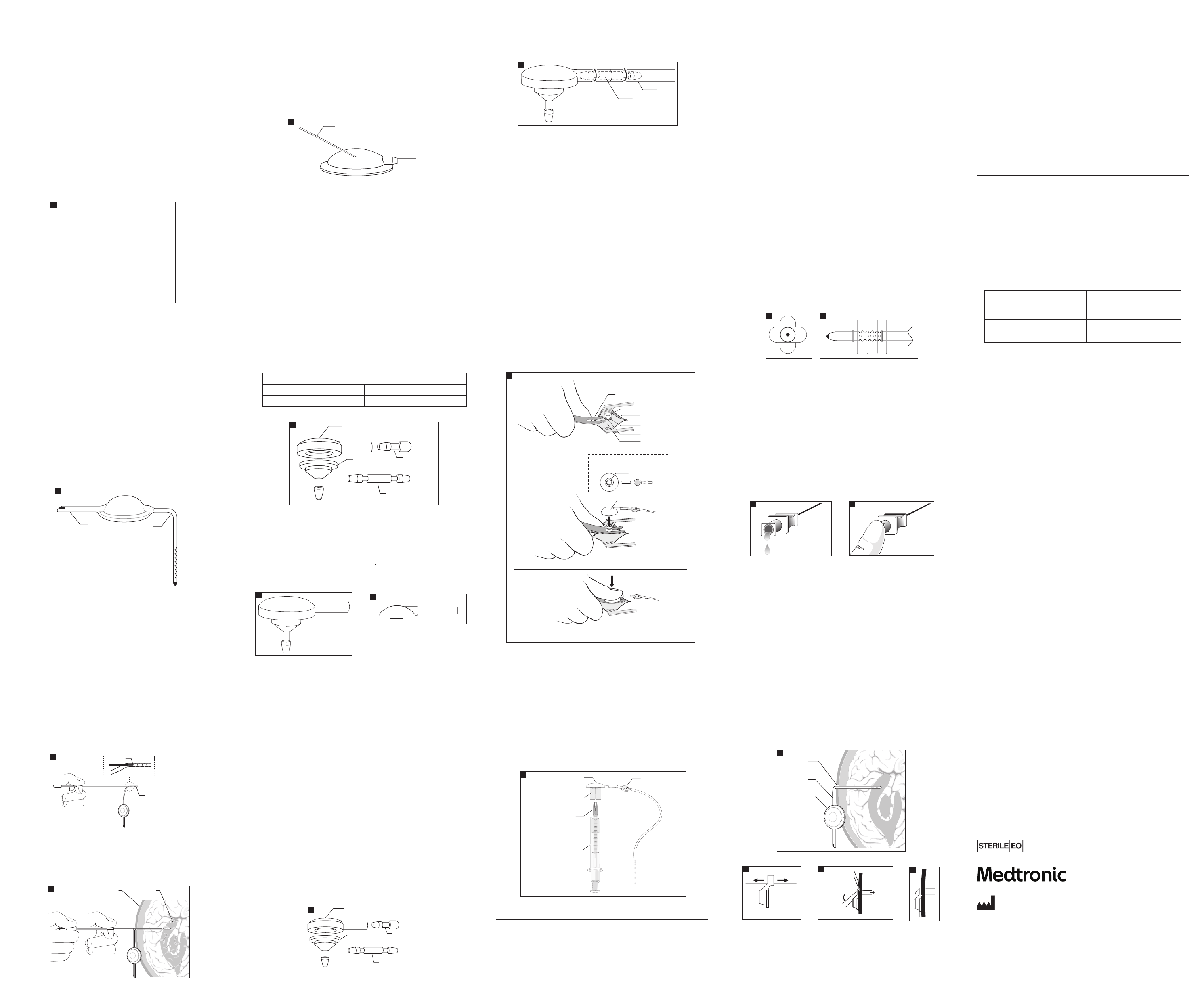
CSF-Ventricular Reservoirs
Skull
Burr hole
To ventricles
push into
t
ab groove
Bend catheter
Twist Drill or
Burr Hole
Ventricular
Catheter
Ventricular
Reservoir
Reservoir Dome
Button Valve
Prefill
Adapter
30 cc Syringe
16-gauge Blunt
Needle Adapter
Cut Here
Preformed Right
Angle Catheter
12 mm Convertible Reservoir
Radiopaque Tantalum
Impregnated Silicone Plug
Flow Hole
Catheter
VentricleSkull
Burr Hole
Ventricular Catheter
Snap Assembly Tool
Incision
Integral Ventriculostomy
Reservoir Dome
Snap Connector
Snap Shunt Assembly
(underside view)
Dura
Skull Surface
Radiopaque Silicone Dome
PlasticTubing
Plug
Plastic Straight
Connector
Plastic Base
Radiopaque Silicone Dome
PlasticTubing
Plug
Plastic Straight
Connector
Plastic Base
25-Gauge or Smaller
Noncoring Needle
Straight Connector
Tubing
Description
CSF-ventricular reservoirs are designed to provide percutaneous access to the ventricular
cerebrospinal uid (CSF) through a silicone elastomer reservoir connected to a ventricular catheter.
CSF-ventricular reservoirs are available in several models, characterized by inlet connector
orientation, dome diameter, and reservoir conguration (Fig 1).
All reser voirs have transl ucent silicone elas tomer domes and are f abricated with a p recision-mo lded,
rm polypropylene base invested in a smooth, exible silicone elastomer housing. The rm
polypr opylene base contr ibutes to struc tural integr ity, and reduces the p otential for penet ration of
the reservoir base by the needle during percutaneous puncture.
All reser voirs have an integ ral catheter conn ector with the e xception of the rese rvoir with inte gral
right angl e catheter. The integ ral connector is d esigned to facili tate implantati on and decrease the
possibility of catheter disconnection. Only one encircling ligature is required to secure the catheter
to the rese rvoir. A radiopaqu e marker is located at t he base of the connec tor, which allows the
physician t o visualize by X-ray the re lative positions o f the catheter and r eservoir in vivo.
Convert ible reservo irs may be integr ated with a Medt ronicNeurosur gery CSF shunt s ystem by cut ting o
the outle t tube plug and conn ecting the ou tlet tube to a shun t valve or a valved cat heter.
Ventricular Catheters
All Medtr onic Neurosurger y CSF-ventric ular reservoi rs are indicated f or use with Medtr onic
Neurosurgery ventricular catheters. See the Ventricular Catheter section o f this insert.
1
Fluid volume capacity of reservoirs (nominal):
30 mm, Side Inle t ........................................... 2.4 m L
28 mm, Side Inle t ............................................1.1 m L
28 mm, Bott om Inlet ......................................1.1 mL
28 mm, Bott om Inlet Convertib le ...................1.1 m L
18 mm, Side Inlet ........................................... 0.3 mL
12 mm, Burr Hole ........................................... 0.6 mL
12 mm, Burr Hole Con vertible ....................... 0.6 mL
12 mm, Convertible ........................................0.1 mL
Indications
All MedtronicNeurosurgery CSF-ventricular reservoirs provide access to the lateral cerebral ventricles,
to cyst ic tumors, and to de bulked tumor cavi ties via hypode rmic punctur e for the inject ion of
chemotherapeutic agents and/or radioisotopes. Reservoirs are useful in obtaining CSF samples for
cytological and chemical studie s, for monitoring ventricular uid pressure, and for ventricular drainage.
All conver tible reser voirs may be used as co mponents of Me dtronicNeurosu rgery CSF-sh unt systems.
Instructions for Use
CSF-Ventricular Reservoirs
The placem ent of the reservo ir may be accomplishe d through a variet y of surgical tec hniques. The
surgica l method and site of pla cement are at the disc retion of the surg eon. The locatio n selected
should pro vide adequate acces s for hypodermic i njection thro ugh the dome. The dome i s designed
to allow inje ction via a 25-g auge or smaller nonco ring needle.
Complete p enetration of th e reservoir by the n eedle will be preve nted in models that con tain a rm
polypropylene base.
The reser voir may be suture d to adjacent tissue by p assing a suture thr ough the fabric-reinf orced
ange or thr ough the suture ho les on the ange of the 12 mm Bur r Hole models.
To adapt the Conver tible models to C SF-shunt compone nts, cut o the outl et tube plug and inse rt a
value or ca theter connect or for assembly wi th value and/or dista l catheter (Fig 2). Refer to t he shunt
system’s Instructions for Use for further information.
2
Ventricular Catheters–Surgical Technique
For ventricular catheter surgical technique see the Ventricular Catheter sec tion of this inser t.
Converti ble 12 mm Reservoir–Pr e-attached Ve ntricular Cathe ter Placement U sing Stylet
A stainle ss steel styl et and polypropy lene plug are suppli ed with the Conver tible 12 mm Reservoir
with inte gral ventricular c atheter model. Th e stylet may be us ed as an aid to place the ca theter in
the ventri cle as follows: cut t he radiopaque, ta ntalum-impre gnated silicone out let plug as shown in
Figure2. Ins ert the styl et through the out let tube into the res ervoir, and caref ully straighten o ut the
angled catheter, pushing the stylet to the proximal end of the catheter. Position the catheter in the
ventric le and withdraw the s tylet, allowin g the angled cathe ter section to re turn to its pref ormed
shape and th e reservoir to lie at against the skull.
At this point t he outlet tube of th e reservoir may be p lugged with the po lypropylene tu bing plug, or
a valved shun t may be attached . In either case, a sing le ligature is requi red to attach the o utlet tube
to a ttin g (plug or straigh t connector).
If the product is packaged with a disposable quick release ventricular catheter introducer, the
instru ctions for use ar e as follows:
Insert t he tip of the introd ucer stylet int o the proximal end of th e ventricular cat heter via the drain
hole closest to the reservoir (Fig 3).
3
Once the de sired catheter lo cation is achieve d, the shaft grip i s held rmly as the st ylet grip is pulle d
back appr oximately 1.5 centime ters (Fig 4). The catheter w ill be released f rom the introduce r by this
action . The introducer may n ow be withdrawn.
4
Injec tion into the Rese rvoir
CSF-Ventric ular Reservoi rs are designed to al low injection th rough the dome by use o f a 25-gauge
or smaller no ncoring or bevele d needle (Fig5). Reser voirs are designe d to allow multiple pu nctures,
and it is rec ommended that the ne edle be insert ed at various loca tions to avoid repeate d punctures
at a single point.
CSF sampl ing may be done by percu taneous access th rough the silicone r eservoir dome u sing a
25 gauge, or sm aller, non-coring ne edle. Puncture s can occur as oft en as desired up to 25 tot al
punctures.
CAUTION: LOW TEAR S TRENGTH IS A CHARACTERIST IC OF MOST UNREINFORCED SILICONE
ELASTOME R MATERIALS. CARE MUST BE TAKEN ON INSERTIO N AND REMOVAL OF THE NEEDLE.
CAUTION: TAKE CARE TO MAINTAIN STERILITY AND TO AVOID PARTICULATE CONTAMINATION.
5
CSF-Ventriculostomy Reservoirs
Description
CSF-Ventriculostomy Reservoirs are designed to provide percutaneous access to the ventricular
cerebrospinal uid (CSF). Any MedtronicNeurosurgery CSF-Ventriculostomy Reservoir can be used
indepen dently as a reser voir or as a compone nt of a MedtronicNe urosurgery C SF-Flow Control Sh unt.
CSF-Ventric ulostomy Reser voirs have a 6 mm-d iameter burr hole, p olypropylene ba se, and a
radiopaque, barium impregnated, silicone elastomer dome.
The rm po lypropylene ba se contributes t o structur al integrity, and re duces the potent ial for
penetration of the reservoir base by the needle during percutaneous puncture.
The base is m ade with an integr al catheter conne ctor designe d to facilitate im plantation and de crease
the possibility of catheter disconnection. One encircling ligature is required to secure the catheter to the
inlet conn ector. The radiop aque reservo ir dome allows the phy sician to visualize b y X-ray the relative
positions of the reservoir dome and the radiopaque catheter if disconnection is suspected. All reservoirs
are speci ally designed to t i nto a 6 mm (1/4”) diam eter burr hole or t wist drill hole. A ny Medtronic
Neurosur gery CSF-Flo w Control valve may be d irectly conne cted to the res ervoirs.
Pull-Over Ventriculostomy Reservoir
The Pull- Over Ventriculos tomy Reservoir (F ig 6) is available in two mo dels: 6 mm Burr Hole Ba se,
Shallow, and 6 mm Bur r Hole Base, Regula r Depth.
The uid volume capacity of the reservoirs is:
Burr Hole, 6 m m Regular Depth: .15 m L
Burr Hole, 6 m m Shallow Depth: .10 mL
6
Unitized Ventriculostomy Reservoir
The Unitiz ed Ventriculosto my Reservoir is on e integral assemb ly. It has a 6 mm base, integra l to the
reser voir dome. The uid volu me capacity of t he reservoir is 0.15 mL (Fig 7).
Snap Assembly Ventriculo stomy Reservoir
The Snap Assembly Ventriculostomy Reservoir facilitates connection of the proximal and distal
componen ts of a CSF-Shunt and sho uld be used with a s nap assembly reservoir base. The uid
volume cap acity of the res ervoir is 0.15 mL (Fig 8).
7
Indications
CSF-Ventriculostomy Reservoirs, when connected to ventricular catheters, provide access to the
lateral cerebral ventricles. They may be used independently as reservoirs, or as components of CSFFlow Control Shunts.
Instructions for Use
Ventricular Catheter Placement
A variet y of surgical tech niques may be used in p lacing the ventric ular catheter. Site of p lacement
is at the disc retion of the surg eon. The ventricu lar catheter may be pl aced into the lateral ve ntricle
using a sta inless steel st ylet as a guide. Af ter placement and tr imming (if necess ary) the catheter
is attac hed to the assembl ed reservoir at t he base inlet conne ctor by an encircl ing ligature. The
assembl ed CSF-Ventriculos tomy Reservoi r is placed in the 6 mm burr h ole or twist dri ll hole.
Alternately, the catheter length may be gauged before insertion and trimmed. After trimming,
the catheter may be xed to the reservoir base by an encircling ligature (non-unitized versions
only). The cath eter and base may then b e placed as an assemb ly using a stainles s steel style t. After
catheter placement, the silicone elastomer cap is tted over the reservoir base, and the assembled
CSF-Ventric ulostomy Reser voir is placed in the b urr hole or twis t drill hole.
CAUTION: DO NOT P UNCTURE THE SILICONE CAP WIT H THE STYLET DURING C ATHETER
PLACEMENT. THIS MAY RESULT IN LEAK AGE THROUGH THE CAP AFTER RE SERVOIR IMPLANTATION.
Reservoir Placement
The placem ent of the reser voir can be accompli shed through a var iety of surgic al techniques. P lacement
method is a t the discretio n of the surgeon. Th e location sele cted for the res ervoir should p rovide adequate
access for i njection thr ough the reser voir dome, and if des ired, allow for the p ossible additi on of a CSF-Flow
Control Sh unt. The reser voirs are design ed to t snugly into a 6 mm b urr hole or twis t drill hole.
Use of Reser voir Only
To use the reser voir without con nection to a CSF- shunt, push the plast ic tubing plug into th e
reservoir dome outlet and secure with one encircling ligature (Fig 9).
8
Use of Reser voir in a CSF-Shunt
To connect the reservoir for use as a shunt component, push the straight connector into the reservoir dome
outlet ar m and secure wit h one encircling li gature. The reser voir is now ready to b e connected to a C SF-Shunt
by suturi ng the connecto r to the inlet tubing o f the shunt. A CSF-F low Control Valve or shun t with an integral
inlet connector may be connected directly to the reservoir, without using the separate connector (Fig 10).
10
Injec tion into the Rese rvoir
The CSF-Ventr iculostomy Res ervoir is design ed to allow injecti on through the dome b y use of a
25-gauge or smaller noncoring needle.
CAUTION: LOW TEAR S TRENGTH IS A CHARACTERIST IC OF MOST UNREINFORCED SILICONE
ELASTOME R MATERIALS. CARE MUST BE TAKEN ON INSERTIO N AND REMOVAL OF THE NEEDLE.
The reservoir is designed to allow multiple punctures. Inserting the needle at various locations to
avoid repea ted punctures a t a single point on the c ap is recommended .
Produc t performanc e tests indicate t hat the CSF-Ventricu lostomy Reser voir will tolerate up t o 100
punct ures with a 25-ga uge or smaller noncor ing needle. Actua l product per formance may var y
depending upon injection technique, needle type and size.
Snap Assembly Ventriculo stomy Reservoir
NOTE: The Snap Assembly Ventriculostomy Reservoir Dome must be used with a Snap
Assembly Base.
NOTE: The Ventricular Catheter with Snap Assembly Base is available separately or as an
integral unit with predetermined catheter lengths.
After th e ventricular cat heter has been place d, and attached to t he reservoir b ase, the reservo ir base
may be snappe d together with t he reservoir do me. A Snap Assembly Tool is av ailable separate ly to
simplif y and expedite t he snap procedure. Sl ip the “prongs” of the to ol under the reser voir base;
then, snap th e dome onto the base (Fi g 11). After the dome a nd base are snappe d together, the
reser voir is placed in the 6 mm b urr hole or twis t drill hole.
WARNING: VERIFY COMPL ETE SNAP ENGAGEMENT AND DO NOT DISA SSEMBLE THE RESERVOIR
AND BASE ONCE THE Y ARE SNAPPED TOGETHER . THE RESERVO IR AND BASE ARE DESIGNED
FOR “ONE-TIME-ONLY” SNAP A SSEMBLY. METICULOUS C ARE MUST BE TAKEN DURING
ASSEMBLY TO PREVENT DAM AGE TO PLASTIC COMPONENT S. DISASSEMBLY AND REASSEMBLY
AND/OR DAMAGE TO THE PL ASTIC COMPONENTS DURING A SSEMBLY CAN RESULT IN
UNWANTED DISCONNEC TION OR IN LEAKAGE OF THE ASS EMBLY.
11
Shunt Patency Test, Snap Assembly Ventriculostomy Reservoir
A prell ada pter and a blunt needl e are provided wit h each Snap Shunt Asse mbly Ventriculos tomy
Reservoir Dome to facilitate preimplantation processing (Fig 12).
Shunt Pate ncy Check
1. Attach t he translucent pre ll adapter to the inle t of the reservoi r dome.
2. Using the 16-gauge blunt needle adapter, ll a syringe with sterile, ltered, isotonic saline.
3. Insert t he blunt needle ada pter into the port o f the prell adapter, and us ing gentle syrin ge
pressure, ush shunt assembly with the saline.
4. If the sali ne ows out of the dist al catheter end, t he shunt assembly is p atent.
Note: Pressure/ow test instruction are available upon request from the Medtronic
Neurosurgery Customer Service department.
12
depth of penetration of the catheter into the lateral ventricle.
Ventricula r catheters are p ackaged with a ri ght angle clip (except fo r catheters desi gned for use
with bur r hole reservoi rs and valves). The right an gle clip package d with the cathete r is designed to
angulate the catheter to lie within the mid-portion of the lateral ventricle.
Each of the c atheters is kin k and compression r esistant, is impr inted with lengt h markers, and is
package d with a stainles s steel style t inserted in the l umen. The proximal en d of the catheter ha s a
single line of inlet holes spaced at 90º intervals around the circumference of the catheter tubing.
Barium Impregnated Ventricular Catheter
Barium Im pregnated Ventric ular Catheters ar e fabricated f rom relatively r m, barium impregna ted
silicone elastomer tubing for radiopacity.
Standard Ventricular Catheters
The Standar d Ventricular Cathe ter has an outer diame ter of 2.5 mm and an inner di ameter of 1.3 mm
(dimensions nominal).
Translucent Ventricular Catheter
The Translucent Ventricular Catheter is fabricated from translucent, non-radiopaque silicone
elastomer tubing.
Translucen t Ventricular Cath eter with Radio paque Stripe
The Translucent Ventricular Catheter with Radiopaque Stripe is fabricated from translucent silicone
elastomer tubing with a radiopaque stripe encased within the tubing wall.
Flanged Ventricular Catheter
The Flanged Ventricular Catheter, available in the small tubing size only, has eight exible silicone
elastom er anges (Fig 13) and has 20 inlet ho les positioned a t 90º intervals ar ound the cathete r
between the anges (Fig 14).
The anges are designed to bend and cover the inlet holes in the catheter tubing during insertion
protec ting the inlet hole s from obstru ction by brain fr agments or bloo d clots. The ange s resume an
extended conguration upon entering the ventricle and help prevent direct contact of the inlet holes
with the c horoid plexus and v entricle wall.
Snap Assembly Ventricular Catheter
The Snap Assembly Ventricular Catheter is fabricated of silicone elastomer and polypropylene,
and is desig ned to be used only wi th a snap assembly re servoir dome. Th e kink-and compress ionresistant ventricular catheter is fabricated with smooth, radiopaque silicone elastomer. The rm
polypr opylene base contr ibutes to struc tural integr ity, and reduces the p otential for penet ration of
the reservoir base by the needle during percutaneous puncture.
13 14
Pliant Ventricular Catheter
The Pliant Vent ricular Cathete r is fabricated f rom a softer (lowe r durometer) silicon e elastomer
tubing.
Ventricul ar Catheter with O pus
®
Stylet
The Opus Vent ricular Cathete rs are packaged w ith an Opus Style t. The Opus Stylet i s designed to
facilit ate introduct ion of the cathete r into the lateral ventr icle. The Opus Sty let has a hollow shaf t, an
entry p ort and an exit po rt, permitt ing visualizati on of CSF during cat heter placement (Fig 15). The
Opus Sty let has a molded luer lock outlet gri p around the exit po rt. Flow of CSF thro ugh the exit por t
may be stopp ed by covering the ex it port with a glo ved nger (Fig 16).
The luerlo ck outlet grip als o allows attachm ent of a syringe fo r CSF sampling.
CAUTION: DUE TO THE LE NGTH OF THE STYLET SHAFT, CSF FLOW THRO UGH THE STYLE SHAFT
MAY NOT OCCUR IN PATIENTS WITH LOW INTR ACRANIAL PRESSURE.
CAUTION: CAR E SHOULD BE TAKEN TO MINIMIZE THE AMOUNT OF C SF ALLOWED TO ESCAPE
THROUGH THE OPUS ST YLET.
15 16
Indications
Ventricula r catheters are d esigned for use a s proximal compon ents of reser voirs for acces s to
cerebros pinal uid. They als o are used as a compo nent of CSF-Flow Con trol Shunts for u se in shunting
cerebros pinal uid from t he ventricles of t he brain into the rig ht atrium of the hea rt or to the perit oneal
cavit y. The small catheter is r ecommended for u se in patients w here a smaller diame ter is indicated.
Instructions for Use
A variet y of surgical tech niques may be used in p lacing the cathet ers into the lateral v entricle. Site of
placement i s at the discretio n of the surgeon.
A stainle ss steel styl et, packaged wi th each catheter, is des igned to facilit ate introducti on of the
cathete r into the lateral vent ricle. The cathete r is packaged wit h the stylet ins erted in the lumen .
Once the ca theter is placed into t he ventricle, the s tylet is withdr awn from the cath eter.
The right a ngle clip may be used to b end the ventricula r catheter to an appr oximate 90º angle w here
it exit s the twist drill o r burr hole (Fig 17). (The cli p must be removed whe n the catheter is use d with
the Burr Ho le Reservoir.) The clip m ay be used as a marker fo r planned depth of ca theter insert ion by
sliding it t he appropriate dis tance from the pr oximal tip of the cat heter prior to ins ertion; this can b e
done with the stylet in the catheter (Fig 18). After the catheter is positioned properly in the ventricle,
the ext racranial por tion of the cathe ter is pressed into t he split tubular se gment of the clip to fo rm
the right a ngle bend (Figures 19 and 20). Avoid s tretching the ca theter when it is pre ssed into the
clip. If the c atheter is to be place d in the ventricle th rough a tubular intr oducer, the clip must be
removed prior to insertion of the catheter through the introducer.
17
18
19
20
CAUTION: LOW TEAR S TRENGTH IS A CHARACTERIST IC OF MOST UNREINFORCED SILICONE
ELASTOME R MATERIALS. CARE MUST BE TAKEN WITH THE HANDLING A ND PLACEMENT OF THE
SILICONE ELAS TOMER CATHETER TUBING TO AVOID CUTS, NICK S, OR TEARS.
Snap Assembly Ventriculostomy Catheter
NOTE: The Ventricular Catheter with Snap Assembly base is available separately or as an
integral unit with predetermined catheter lengths.
After th e ventricular cat heter has been place d, and attached to t he reservoir b ase, the reservo ir base
may be snappe d together with t he reservoir do me. A Snap Assembly Tool is av ailable separate ly to
simplif y and expedite t he snap procedure. Sl ip the “prongs” of the to ol under the reser voir base;
then, snap th e dome onto the base (Se e Fig 13, Snap Shunt Assembly). After the do me and base
are snappe d together, the reser voir is placed in the 6 m m burr hole or twi st drill hole.
WARNING: VERIFY COMPL ETE SNAP ENGAGEMENT AND DO NOT DISA SSEMBLE THE RESERVOIR
AND BASE ONCE THE Y ARE SNAPPED TOGETHER. THE RESER VOIR AND BASE ARE DESIGNED
FOR “ONETIME ONLY” SN AP ASSEMBLY. METICULOUS C ARE MUST BE TAKEN DURING
ASSEMBLY TO PREVENT DAM AGE TO PLASTIC COMPONENT S. DISASSEMBLY AND REASSEMBLY
AND/OR DAMAGE TO THE PL ASTIC COMPONENTS DURING A SSEMBLY CAN RESULT IN
UNWANTED DISCONNEC TION OR IN LEAKAGE OF THE ASS EMBLY.
Cardiac/Peritoneal Catheter with Closing Pressure
Description
Cardiac /Peritoneal Cat heter, Closing Pressu re, Low, Medium, or High, is avai lable in a variet y of
congurations. They are fabricated from radiopaque silicone elastomer tubing. Relatively rm
catheter tubing is incorporated into the catheter design to provide resistance to catheter kinking and
occlusio n. Black length mar kers are made of graph ite-impregna ted silicone elast omer material. The
shape of the t ip is designed for c ardiac or perito neal placement. Cere brospinal uid ex its the cathete r
through t he distal slit open ings. The slit openi ngs are coated with g raphite during ma nufacture to
minimize the possibility of slitted surface adhesion during storage. The slit openings are tested to
conform t o a specic closin g pressure range. Th ey are not designed as pressure/ow control valves.
They are designed to provide a dened closing pressure range only.
In produc tion, the group ave rage closing pres sure is measured and c ompared to speci cations as
an average cl osing pressure f or the lot of cathete rs. The closing pr essure range is ide ntied by a dot
code at the di stal end of the cat heter as shown below :
Dot Code Closing Pressure Closing Pressure Range (cmH2O)
• Low 1.5 – 5.4
•• Medium 5.5 – 9.4
••• High 9.5 – 14.4
Indications
The Cardi ac/Peritoneal C atheter, Closing Pres sure Low, Medium or High, is d esigned as a dist al
componen t of a CSF-Flow Contro l Shunt for use in shun ting cerebrospin al uid (CSF) from the
ventric les of the brain into th e right atrium of th e heart or to the per itoneal cavity.
Instructions for Use
A variet y of surgical tech niques may be used to p lace the catheter s into the right atri um, peritoneal
cavit y, or other C SF diversion site. Si te of placement is at the d iscretion of th e surgeon. The surge on
may trim the p roximal end for the s elected place ment site at the time of su rgery. The cathet er
should be c hecked for patenc y at the time of surge ry including vi sual determinatio n that all slit
openings will allow ow of cerebral spinal uid.
If the surge on desires to veri fy that the closi ng pressure of the c atheter is within t he range of
perfo rmance as labeled, a v ariety of techn iques may be used. Th e method is at the dis cretion of the
surgeon.
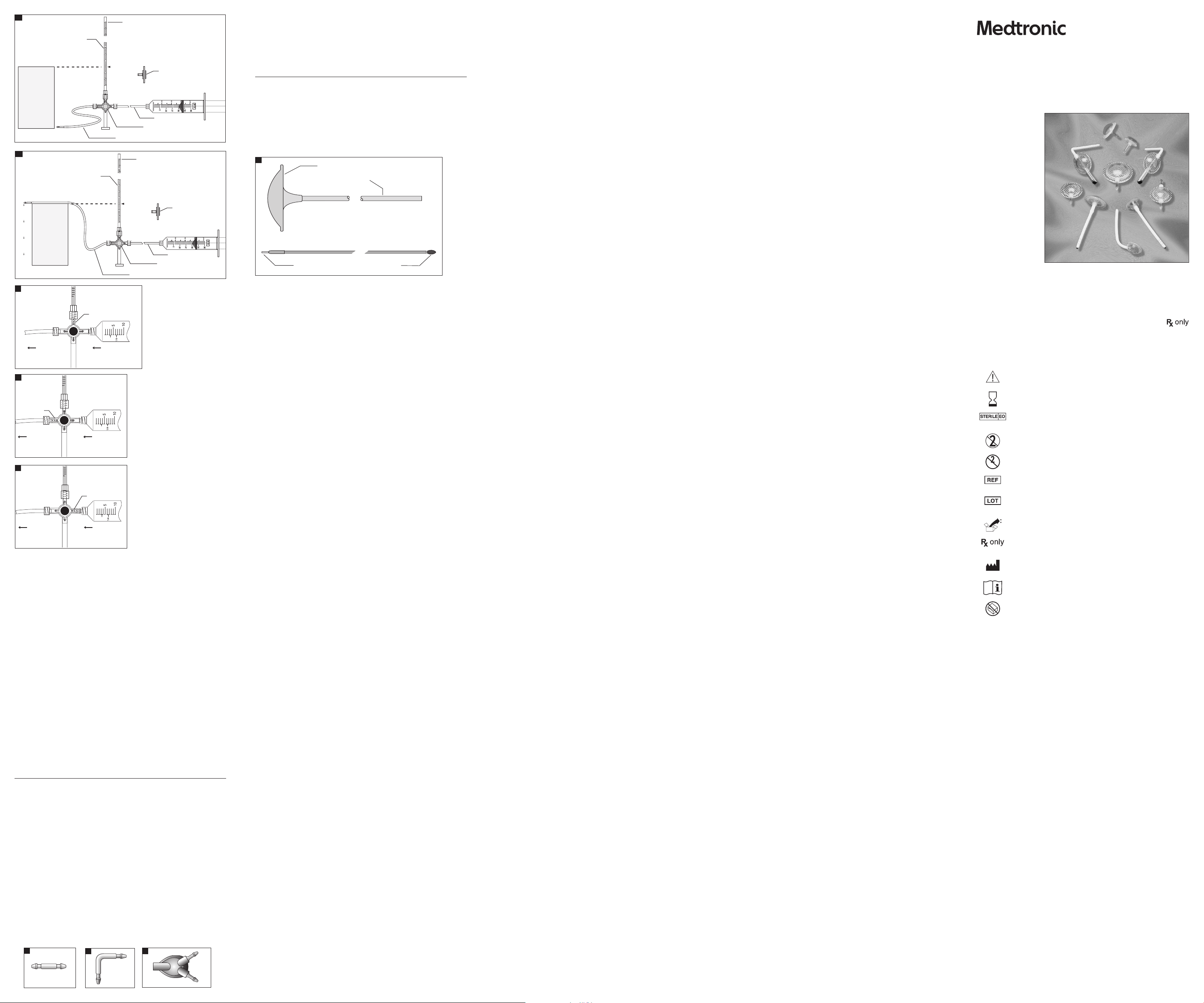
Closing Pressure Test
CAUTION: TAKE CARE TO MAINTAIN STERILITY AND TO AVOID PARTICULATE CONTAMINATION.
Test Method
I. Equipmen t required for thi s test:
1. Suppor t for catheter
2. Sterile 30 cm w ater manometer, gradua ted in millimeters , with 3-way stopcoc k at base
3. Sterile sy ringe, 30 cc to 50 cc
4. Sterile 5 µ syringe lter
5. Sterile tubing adapter
6. Sterile silicone tubing
7. Catheter Connector
II. Equipme nt setup
1. Set up mano meter so that the zero l evel on the manometer a nd the support f or the catheter are
at the same h eight (Fig 21a).
2. Fill syringe with sterile water using 5 µ syringe lter. (When relling syringe, always use 5 µ
syringe lter.) After lling syringe, detach syringe lter.
3. Connect syringe, manometer, and silicone tubing as shown in Figure 21a using straight
connector as needed.
4. To purge all air f rom the assembled s terile test app aratus, turn sto pcock as shown in Fig ure 22.
5. Flush with s terile water fro m syringe.
X369-1E
2018 - 10
© 2018 Medtronic, Inc.
9
Ventricular Catheters
Description
Ventricula r Catheters are ava ilable in a variet y of conguration s: small and standar d sizes; dierent
lengths; w ith or without ang es; barium impreg nated; translucent o r translucent wit h stripe; pliant;
and snap ass embly. See package la bels for congura tion details.
The catheter has a bullet-shaped tip lled with radiopaque silicone elastomer. Black length
markers m ade of a graphite-i mpregnated silicon e elastomer are posi tioned on the cath eter at
points 5, 10, and 15 cm (+/- 0.25 cm) from t he proximal tip to enab le the surgeon to gauge t he
See Snap Assembly Ventriculostomy Reservoir section for snap shunt assembly.
It is recomm ended that the rig ht angle clip be secu red to adjacent tissu e by passing suture s
through t he two suture hole s on the sides of the cli p (Fig 17). If the right angle cli p is not used, it is
recommen ded that the surge on trim the rim of the t wist drill or bu rr hole to provide a be veled notch
where the catheter emerges and curves to lie adjacent to the skull.
Medtronic, Inc.
710 Medtronic Parkway NE
Minneapolis, MN 55432
USA
+1 800 468-9710 USA/Canada
+1 901 344-0645 International
+1 800 468-9713 FAX USA/Canada
+1 901 396-2698 FAX International
medtronic.com
manuals.medtronic.com
Page 2
Polypropylene Handle
Stainless Steel Shaft
Catheter Connection
Polypropylene Obturator Tip
Off
From Syringe
To Catheter
0
Off
From Syringe
To Catheter
0
0 cm
30 cm
Manometer
Stopcock
Syringe Filter
Silicone Tube
Silicone Tubing and Catheter Connector
Off
From Syringe
To Catheter
0
0 cm
30 cm
Manometer
Stopcock
Syringe Filter
Silicone Tube
Silicone Tubing and Catheter Connector
21a
21b
22
23
24
III. Equipment calibration
1.
Turn stopcoc k as shown in Figure 2 3 and ll manometer to a t least 5 cm H2O.
2. With cat heter held at zero level, t urn stopcock to i solate syringe f rom the manometer (F ig 24).
3. Allow water co lumn in the manomete r to fall.
4. Water column sh ould stop at zero leve l of the manometer (Fig 21a).
5. Manomete r is now calibrated to z ero level. Fix or mount t he manometer to maint ain this
reference position.
IV. Test procedure
NOTE: For cor rect result s, the zero level of t he manometer mu st be properl y aligned with
the distal slit openings of the catheter.
1. Connec t the sterile cath eter to be tested to th e assembled ster ile test apparat us (Fig 21b). The
catheter tip should not be touching any substance.
2. Turn stopcoc k as shown in Figure 23 a nd ll manometer to at le ast 30 cm H2O.
3. Turn stopcoc k to isolate manomet er from ow path as sh own in Figure 22.
4. Purge all air f rom the cathete r and the assemble d test apparatus by g ently ushing wit h sterile
water fro m syringe.
5. Gently es tablish ow throu gh the catheter wi th sterile water f rom the syringe.
6. While ge ntly maintaining ow through the cat heter, turn stopco ck to isolate syr inge from ow
path as show n in Figure 24. After st opcock is placed in p roper positio n, the water column in t he
manomete r should start t o fall. The syrin ge is now isolated f rom the catheter a nd continuing ow
with the s yringe is no longe r necessary. If wa ter column does not f all, repeat steps 2 t hrough 6.
7. Allow water column in manometer to stabilize. The column of uid in centimeters from the slit openings
(zero level) to t he top of the uid colum n in the manometer is re corded as the clos ing pressure.
Catheter Connectors
Description
Catheter Connector, Straight
The Cathe ter Connector, Strai ght (Fig 25), is a nylon connec tor designed f or use with ventric ular and
distal catheters.
Catheter Co nnector, Right An gle
The Cathe ter Connector, Right A ngle (Fig 26), is a nylon connec tor designed fo r use with ventric ular
catheters.
Catheter Connector, 3-Way
The Cathe ter Connector, 3-Way (Fig 27), is a pol ypropylene and si licone elastomer co nnector
designe d to connect two ve ntricular cathe ters to one CSF-ow c ontrol valve inlet c onnector.
Indications
Catheter Connector, Straight
The Cathe ter Connector, Strai ght, is indicated f or use when distal o r ventricular cat heter revision is
require d, or to connect a vent ricular cathet er to the inlet por t of a valve.
Catheter Co nnector, Right An gle
The Cathe ter Connector, Right A ngle, is indicated f or use to angulate the ve ntricular cathe ter to a 90º
angle (nomina l) where it exits t he twist drill or b urr hole.
25
26
27
Catheter Connector, 3-Way
The Cathe ter Connector, 3-Way, is indic ated for use when t wo ventricular cat heters are conne cted to
one CSF- ow control valve.
Instructions for Use
The surgic al technique emp loyed in the use of cath eter connecto rs is at the discret ion of the surgeon.
Disposable Subcutaneous Catheter Passer, 38 and 60 cm
Description
The Dispo sable Subcutan eous Catheter Pas sers are dispos able surgical ins truments (Fig 28). They a re
available i n two lengths, 38 cm an d 60 cm, and consist of t wo components:
1. A tubular sh aft with polyp ropylene D-shap ed handle
2. An obtura tor with bullet-shap ed tip
The instruments are designed as malleable subcutaneous tunneling devices for passing
cerebrospinal uid shunt catheters.
28
Indications
The Dispo sable Subcutan eous Catheter Pas sers are used for t he placement of the pe ritoneal cathe ter
component of a cerebrospinal uid shunt or for the placement of the lumboperitoneal catheter.
Instructions for Use
The surgic al technique emp loyed in the use of the Di sposable Subcu taneous Cathet er Passers is at
the discr etion of the surge on. The surgeon is ad vised to ensure that t he catheter will p ass through
the inst rument prior to be ginning the proced ure. The tubular shaf t is malleable and m ay be handformed b y the surgeon as indi cated for the oper ative procedure s. When the instr ument is passed
subcut aneously, the obtura tor must be inser ted in the tubular sha ft and secure d in the handle by
snapping t he obturator’s lock ing tip into positi on. After removal o f the handle and obtu rator, the
cathete r may be hand-fed thr ough the lumen of the tu bular shaft.
The obtur ator also includes a c atheter atta chment site for at tachment of an open e nded distal
cathete r. Attac hment of the cathe ter to the obturator a llows catheter s of appropriate I.D. (in ner
diameter) to b e pulled through th e passer shaft.
How Supplied
Each Med tronic Neurosur gery produc t is packaged ster ile and non-pyrogenic in a double-wr ap
packagi ng system and is inte nded for single (one-time) use only. The double w rap system
facilit ates the prefer red method of ster ile product tr ansfer from th e circulating area to t he sterile
eld. Do not u se if package has b een opened previo usly or damaged. Do n ot resterilize. Re sterilizatio n
can damage the product, potentially leading to patient injury. MedtronicNeurosurgery is not
respons ible for the perf ormance of any prod uct that has been re sterilized.
Storage Conditions
Store devic es in dry, clean condit ions at normal indo or ambient room tem perature.
Contraindications
CSF-Ventricular Reservoirs should not be implanted if there is infection in the scalp or other areas
through w hich the catheter w ill traverse, or if i nfection is pre sent in any area of the b ody. The
exceptio n to the foregoing co ntraindicatio n is the use of the devic e to treat inammator y diseases
involving the central nervous system, e.g., mycotic or other meningitides or brain abscess.
Shunting o f CSF into the right at rium, peritoneal c avity, or other area s of the body should no t be
carrie d out if there is infe ction in any areas i n which the variou s components of the s hunt system
will be impl anted. These incl ude infection s of the scalp and oth er sin area through wh ich the shunt
system will traverse, the meninges and cerebral ventricles, peritoneum, and intraperitoneal and
retrop eritoneal organs , pleura and blood s tream. CSF shuntin g is contraindica ted if there is infec tion
present i n any area of the body. Addit ionally, shunting into t he atrium of patien ts with congenit al
heart disease or other serious cardiopulmonary abnormalit ies is contraindicated.
Patient Education
It is the resp onsibility of t he physician to educ ate the patient and/or t heir representa tive(s)
regarding the use of ventricular reservoirs and CSF shunting. This should include a description of
the compli cations associ ated with implant able shunt system s, and an explanatio n of potential
alternative products and treatments.
Warnings and Precautions
If the ventr icular catheter b ecomes detach ed from the reser voir, it may be withdra wn from, or lost
in, the later al ventricle of the b rain.
Physicians who infuse chemotherapeutic drugs in this device must assure themselves of the
compatib ility of the drug w ith silicone elas tomers and polyp ropylene material s. Some change in
drug pote ncy may occur when i t is in contacted wi th reservoir an d catheter materi als.
Overdra inage of CSF may predi spose developmen t of a subdural hemato ma or hydroma or collaps e
of the lateral ventricular walls leading to obstruction of the ventricular catheter.
The per formance charac teristics o f this device may be alter ed if component s or devices of other
manufac turers are use d in conjunction w ith this device.
The appro priate produc t and size must be chos en for the speci c patient’s needs, b ased on
diagnos tic tests and phys ician experien ce. Incorrect se lection may lead to c omplications. P roduct
labeling species applicable product per formance levels or ranges.
The use of co mponents or dev ices of other manu facturer s in conjuncti on with Medtro nic valves has not
been veri ed. The perf ormance chara cteristic s of this device may b e altered if comp onents or devic es of
other manufacturers are used in conjunction with this device. The perfor mance chararcterstics are veried
for all Med tronic shunt com ponents, whic h are designed to be i nterchangeab ly connected w ith each other.
Avoid contac ting implantab le products w ith lint, glove talc, o ily residue from s kin, oil based soa ps,
synthetic detergents or other surface contaminants.
Improper use of instruments in the handling or implantation of reservoir products may result in the
cutti ng, slitting or cr ushing of compone nts. Such damage may le ad to loss of reser voir integrit y,
and neces sitate premature s urgical revisio n of the reservoi r system. Do not ben d or fold the device
during ins ertion beca use this may cause de vice damage.
Care must be taken to ensure that particulate contaminants are not introduced into shunt components
during preimplanation testing or handling. Introduction of contaminants could result in improper
performance (overdrainage or underdrainage) of the shunt system. Particulate mater that enters the
shunt system also may hold pressure/ow-controlling mechanisms open, resulting in overdrainage.
In securing catheters to connectors, the encircling ligatures should be fastened securely but not too
tightly, least they eventually cut through the silicone tubing.
Care must be taken in the routing of catheters to prevent kinking and needless abrasion along their
course. T he rim of the twis t drill or burr hole may b e trimmed to provi de a beveled notch whe re the
ventric ular catheter emer ges and is curved t o lie adjacent to the skul l.
Patients with hydrocephalus shunt systems or implantable ventricular reservoirs must be kept under
close obs ervation in the p ostoperative p eriod for signs an d symptoms that sug gest malfunc tion. The
clinical ndings may indicate infection or other complications.
Obstr uction may occur i n any of the component s of the ventricula r reservoir or shu nt system. The
system m ay become internall y occluded due to tis sue fragments, b lood clots, tumo r cell aggregates,
bacter ial colonizatio n, or other debris. C atheters that con tact internal bo dy structu res can become
kinked, or b locked at their tips (e.g., in vestment of a ventr icular catheter t ip into the choroid p lexus).
Finally, obst ruction may occ ur due to growth of an i nfant or child, or phy sical activi ties, which resul t
in disconn ection of the com ponents, or with drawal of a distal c atheter from it s intended access si te.
Ventricular reservoir systems may fail due to mechanical malfunction.
If the ventr icular catheter b ecomes bound to th e choroid plexus o r adjacent brain tis sue by brous
tissue adh esions, it is sugge sted that it should n ot be forcibly remo ved. It is suggeste d that gentle
rotatio n of the catheter may he lp to free it. It is adv ised that the cath eter be left in pl ace rather than
risk intraventricular hemorrhage, which may be caused by forcible removal.
“Small” si ze catheters have th inner walls and lower ove rall strength as co mpared with “Sta ndard”
size cathe ters. These cha racteristic s result in a compa ratively greater po tential failure (f racture) rate
and, there fore, shorter li fe expectan cy for “Small” siz e catheters. Phys icians who implant “ Small”
size cathe ters for cosmet ic reasons must ack nowledge the pot entially higher rate o f catheter revisi on
and weigh thi s against the cosme tic benets.
Clotti ng around the atria l portion of a cat heter may lead to embol ization of the pulm onary arteri al
tree with resulting cor pulmonale and pulmonary hypertension.
Disconnected shunt components may further migrate into the heart, or into the peritoneal cavity.
Shunt systems may fail due to mechanical malfunction, leading to underdrainage or overdrainage.
Malfunc tion or obstr uction of the shun t system may lead to sig ns and symptoms of in creased
intracranial pressure if the hydrocephalus is not compensated. In the infant, common ndings are
increas ed tension of the anter ior fontanelle, co ngestion of sc alp veins, listless ness, drowsiness a nd
irritability, vomiting, and nuchal rigidity. Other children and adults will develop signs and symptoms
commonly a ssociated with i ncreased intra cranial pressur e such as headaches, vo miting, blurri ng of
vision, nuchal rigidity, deterioration of consciousness and variable abnormal neurological ndings.
Subcut aneous catheter p assers can brea k at welds or componen t assembly point s, or as a result
of extr eme deformatio n of the malleable shaf t. Sudden break age can lead to traum a of tissues
or organs, an d damage to the implant able system. Ins truments mus t be inspected p rior to use to
ensure continued integrity and functionalit y. Disposable instruments must never be reused, or injury
to the patie nt and physician is po ssible.
Care should be taken to avoid plugging the holes in the ventricular catheter with brain fragments
during it s passage throu gh the cerebral cor tex into the ventr icle. The tip of the ca theter should
not be advan ced anterior to the f oramen of Monro if it i s introduced into t he lateral ventric le via a
parieto -occipital a pproach. This may c ause the catheter t o become embedde d in the frontal lob e if
the ventri cle becomes redu ced in size.
It has been r eported that a ver y small populatio n of patients may show a n acute allergic-type
reacti on to the ventricula r reservoir sy stem. This may be due to i ts materials of fab rication, and can
lead to patient discomfort tissue erosion, or other complications.
Complications
Complica tions associate d with the use of the se products may b e similar to those ex perienced in any
surgica l procedure carr ied out under loc al and/or general anes thesia. These in clude reactio ns to
drugs and a nesthetic agen ts, electrol yte imbalance, car diac arrhythm ias, and excessive blo od loss,
parti cularly in infant s. The patient may ra rely exhibit a reac tion due to sensi tivity to the imp lant.
Additional complications associated with neurosurgical procedures include seizure, hemorrhage,
and neurologic decit/dysfunction.
Use of non- ltered or non-co ntrolled uids fo r testing may resul t in improper devic e performance a nd
necessitate device revision. Devices must be handled in controlled hospital environments to prevent
the intro duction of par ticles, bers o r other contaminan ts into the valve.
In CSF shunt ing procedures, t he most common comp lications are due t o obstructio n of the system
as descr ibed under “Warni ngs and Precauti ons.” Obstruct ion may occur in any comp onent of the
system d ue to plugging by brain f ragments, blo od clots, and/or tum or cell aggregates a t some point
along its c ourse. Obstr uction also may occ ur because of sep aration of the sys tem components o r
kinking and/or coiling of the catheter. This may predispose migration of the ventricular catheter
into the late ral ventricle and th e distal cathet er into the heart an d pulmonary ar terial tree, the
peritoneum, or other structure in which the catheter is implanted. Migration into the pleural cavity
may lead to pleu ral eusion. Shun t disconnecti on may also occur due to g rowth of an infant o r child,
or physic al activities w hich result in disc onnection of th e shunt component s or withdrawal of a di stal
cathete r from its intend ed drainage site. Dis connection may c ause complicat ions. Disconnec ted
shunt components may migrate.
Local and systemic infections due to organisms inhabiting the skin, particularly Staphylococcus
epidermidis, may occur. Other p athogens circu lating in the bloods tream may colonize t he shunt
and, in the maj ority of patie nts, require it s removal. Rigorous p erioperative co ntrol of the opera ting
environm ent and the use of antib iotics at the phys ician’s discretion may av ert infecti on occurrence.
Infec tion rates may be dec reased with the us e of antibiotics , short duratio n of surgery (surgi cal
experience) and control of the operating room environment (e.g., designated operating room,
limited pe rsonnel and tra c, covered skin sur faces). Results als o can be obtained wi thout the use of
antibiotics, but with rigorous perioperative control of the environment.
The use of pr ophylactic ant ibiotics is some what controversi al because their u se may predispose
infec tion by resistan t organisms. There fore, the decisio n to use antibiotic s prophylactic ally rests
with the at tending physici an and/or surgeon.
CSF overdr ainage may result in e xcessive reduct ion of intracran ial pressure and pr edispose the
developm ent of a subdural hema toma or hygroma, and exce ssive reducti on of ventricular si ze
leading to obstruction because of impingement of the ventricular walls on the inlet holes in
the cathe ter. In rare cases, spi nal abnormalitie s have been associa ted with overdrain age. In
infant s, excessive press ure reduction d ue to overdrainage wi ll cause a marked dep ression of the
anterior fontanelle, overriding of cranial bones and may convert communicating into obstructive
hydrocephalus.
Intra-abdominal complications associated with peritoneal shunting include perf oration of the small or large
bowel with resultant peritonitis, perforation of other viscera, ureteral obstruction, adhesions, migration of
the catheter into unintended anatomical locations, and development of ascites and pseudocysts.
CSF overdr ainage has in rare ca ses been associ ated with spinal abn ormalities such a s myelopathy.
Neurosur gical procedur es such as CSF shunti ng carry risk s associated wi th brain tissue mani pulation,
includin g neurologic dec it/dysfunc tion, seizure, and s troke. Other surg ical risks incl ude bleeding
complications, inadvertent introduction of air into the pleural space (pneumothorax), and wound
healing problems such as wound dehiscence.
In rare cas es, seeding of tum or cells along cathe ter lengths has be en reported.
Returned Goods Policy
Produc ts must be retur ned in unopened p ackages, with man ufacturer ’s seals int act, to be accepte d
for replac ement or credit, u nless returned d ue to a complaint of pro duct defec t or mislabeling
Determi nation of a produc t defect or misl abeling will be made by M edtronic Neuro surgery, which
determination will be nal.
Produc ts will not be accept ed for replacement o r credit if they have b een in possessio n of the
custom er for more than 90 days .
Warranty
A. Standa rd Limited Warr anty. Medtronic Ne urosurgery wa rrants to the ori ginal end user
purchaser (“Purchaser”) that the enclosed single use product (“Product”) purchased by Purchaser,
at the time of d elivery to Purch aser, shall be substant ially free from d efects in mate rial and
workmans hip. Medtronic Neu rosurgery make s no warranty (exp ress, implied or s tatutory) for
Produc ts that are modi ed (except as express ly contemplated her ein) or subjected to un usual
physical stress, misuse, improper operation, neglect, improper testing, use in combination with
other pro ducts or compo nents other than th ose for which the Pr oducts were de signed, or use in any
manner or medical procedure for which the Products are not indicated.
B. Remedy. Purc haser’s exclusi ve remedy and Med tronic Neurosu rgery’s sole lia bility for br each of the
foregoi ng warranty s hall be, at Medtron ic Neurosurger y’s sole option a nd election, t o replace the Prod uct
or credi t Purchaser for t he net amount ac tually paid for any s uch Product , provided that (i) Me dtronic
Neurosur gery is noti ed in writing wi thin ninety (90) day s after Purcha ser’s receipt of th e Product that s uch
Produc t failed to confo rm, including a d etailed expl anation in English o f any alleged nonco nformity; (i i)
such Prod uct is return ed to Medtronic N eurosurger y within ninet y (90) days after Pur chaser’s receip t of the
Produc t F.O.B., 125 Cremona D rive, Goleta, Ca lifornia 93117, USA., or as other wise design ated by Medtron ic
Neurosurgery; and (iii) Medtronic Neurosurgery is reasonably satised that the claimed nonconformities
actual ly exist. Exce pt as expressl y provided in this p aragraph, Purc haser shall not have t he right to retur n
Products to Medtronic Neurosurgery without Medtronic Neurosurgery’s prior written consent.
C. Exclu sion of Othe r Warranties. E XCEPT FOR THE LIMITED WARRANT Y PROVIDED IN (A)
ABOVE, MEDTRONI C NEUROSURGERY GRANTS NO O THER WARRANTIES OR CONDITIONS, E XPRESS
OR IMPLIED AND MANUFACTURER SPECIFICALLY DISCLAIMS THE IMPLIED WARRAN TIES AND
CONDITIONS OF MERCHANTABILITY AND FITNESS FOR A PARTICULAR PURPOSE. MEDTRONIC
NEUROSURGERY NEITH ER ASSUMES NOR AUTHORIZES A NY OTHER PERSON TO ASSUME AN Y OTHER
LIABILITIES ARISING OU T OF OR IN CONNECTION WITH THE SALE O R USE OF ANY PRODUCT.
CSF-Ventricular Reservoir
Products and Accessories
Instructions for use
Symbols
Caution
Use by
Sterilization: Ethylene-Oxide Gas
Do Not Reus e
Do Not Resterilize
Sterilize
Reference Number
Lot Number
Package Contents
Cautio n: U. S. federal law re strict s this device to s ale by or on the ord er of a physicia n.
Manufacturer
Consult Instructions for Use.
Do not use i f package is op en or damaged.
The foll owing is a trade mark or regis tered trade mark of Medtr onic, Inc. in th e United States a nd other count ries:
Delta™. All ot her trademar ks, servi ce marks, reg istered tr ademarks or r egistered s ervice mar ks are the pro perty of
their re spective ow ners in the Uni ted States and o ther countri es.
 Loading...