

Page 1
Integrated Power Console (IPC®) System
Rx Only
MODEL: 2340000
User’s Guide
Page 2

The information contained in this document is accurate at time of publication. Medtronic reserves the right to make changes to
the product described in this manual without notice and without incorporating those changes to products already sold. Released
documents are available to view or print at manuals.medtronic.com.
The following are trademarks or registered trademarks of Medtronic, Inc. in the United States and other countries: CD HORIZON®,
Endo-Scrub®, Hydrodebrider®, Indigo™, Intelliow®, IPC®, Legend®, Legend EHS®, Legend EHS Stylus©, Magnum®, Midas Rex®,
Mednext®, NIM®, NIM-Eclipse®, Powerease™, Skeeter®, SOLERA®, StraightShot®, Stylus Touch®, Triton®, TSRH® 3Dx™ , Visao® and
XPS®. All other trademarks, service marks, registered trademarks, or registered service marks are the property of their respective
owners in the United States and other countries.
Page 3

TABLE OF CONTENTS
SYMBOLS ......................................................................................................................................... 1-1
GLOSSARY........................................................................................................................................ 1-1
CUSTOMER SERVICE ....................................................................................................................... 1-1
INDICATIONS FOR USE ................................................................................................................... 1-2
DEVICE DESCRIPTION .................................................................................................................... 1-2
CONTRAINDICATIONS .................................................................................................................... 1-2
WARNINGS ....................................................................................................................................... 1-2
PRECAUTIONS ................................................................................................................................. 1-4
SYSTEM REQUIREMENTS AND SPECIFICATIONS.........................................................................1-5
SYSTEM SOUNDS AND FIGURES ................................................................................................... 1-6
PRE-OPERATING INSTRUCTIONS .................................................................................................. 1-8
When the System Arrives .............................................................................................................................................................................1-8
Set up the IPC ...................................................................................................................................................................................................1-8
Install the Pump Cartridges or Irrigation Tubing .................................................................................................................................1-8
Prepare the IPC for Use .................................................................................................................................................................................1-8
Calibrate Touchscreen ...................................................................................................................................................................................1-8
Change System Settings ..............................................................................................................................................................................1-8
Set up and Prime Pumps ..............................................................................................................................................................................1-9
Conrm System Operation ....................................................................................................................................................................... 1-10
IPC COMPONENTS ........................................................................................................................ 1-10
Multifunction Footpedal............................................................................................................................................................................1-10
IntelliFlow Irrigation Remote Control ................................................................................................................................................... 1-10
Auxillary Power Console ............................................................................................................................................................................ 1-10
POST-OPERATIVE INSTRUCTIONS .............................................................................................. 1-10
Disconnect Accessory Cable from Console ........................................................................................................................................1-10
Clean the Multifunction Footpedal ....................................................................................................................................................... 1-10
GUIDANCE AND MANUFACTURER’S DECLARATION - ELECTROMAGNETIC IMMUNITY ....... 1-11
LIMITED WARRANTY ..................................................................................................................... 1-13
FOR ITEMS CONTAMINATED WITH TSE AGENTS ....................................................................... 1-13
TRITON ELECTRIC HIGH-TORQUE HANDPIECE ............................................................................ 2-1
SUCTION IRRIGATOR ...................................................................................................................... 3-1
ENDO-SCRUB 2 ................................................................................................................................ 4-1
SPINE SHAVER (SC1) HANDPIECE ................................................................................................. 5-1
STRAIGHTSHOT M4, STRAIGHTSHOT MAGNUM II AND STRAIGHTSHOT III ............................ 6-1
LEGEND EHS AND LEGEND EHS STYLUS ...................................................................................... 7-1
STYLUS TOUCH ................................................................................................................................ 8-1
LEGEND EHS, LEGEND EHS STYLUS AND STYLUS TOUCH ATTACHMENTS .............................. 9-1
SKEETER ULTRA-LITE OTO-TOOL ................................................................................................ 10-1
VISAO HIGH-SPEED DRILL ........................................................................................................... 11-1
Page 4

INDIGO HIGH-SPEED OTOLOGIC DRILL ...................................................................................... 12-1
MIDAS REX MICROSAWS .............................................................................................................. 13-1
POWEREASE DRIVER .................................................................................................................... 14-1
TROUBLESHOOTING AND ERROR CODES .................................................................................... A-1
CLEANING AND STERILIZATION .................................................................................................... B-1
Triton Electric High-Torque Handpiece ............................................................................................................................M000030A322
Endo-Scrub 2 ......................................................................................................................................................................................... 68E4005
Midas Rex Spine Shaver, StraightShot M4, StraightShot Magnum II or StraightShot III ............................................ 68E3282
Legend EHS and Legend EHS Stylus .................................................................................................................................M000030A234
Stylus Touch ...........................................................................................................................................................................................68E4132
Legend Attachments ..............................................................................................................................................................M000030A235
Skeeter Oto-ex Burs .......................................................................................................................................................................... 68E3968
Skeeter Handpiece ..............................................................................................................................................................................68E3969
Visao .........................................................................................................................................................................................................68E3281
Indigo High-Speed Otologic Drill ..................................................................................................................................................68E4187
Indigo High-Speed Otologic Drill Attachments .......................................................................................................................68E4188
Microsaws ...................................................................................................................................................................................M000030A231
POWEREASE Driver ..............................................................................................................................................................................68E4189
Page 5
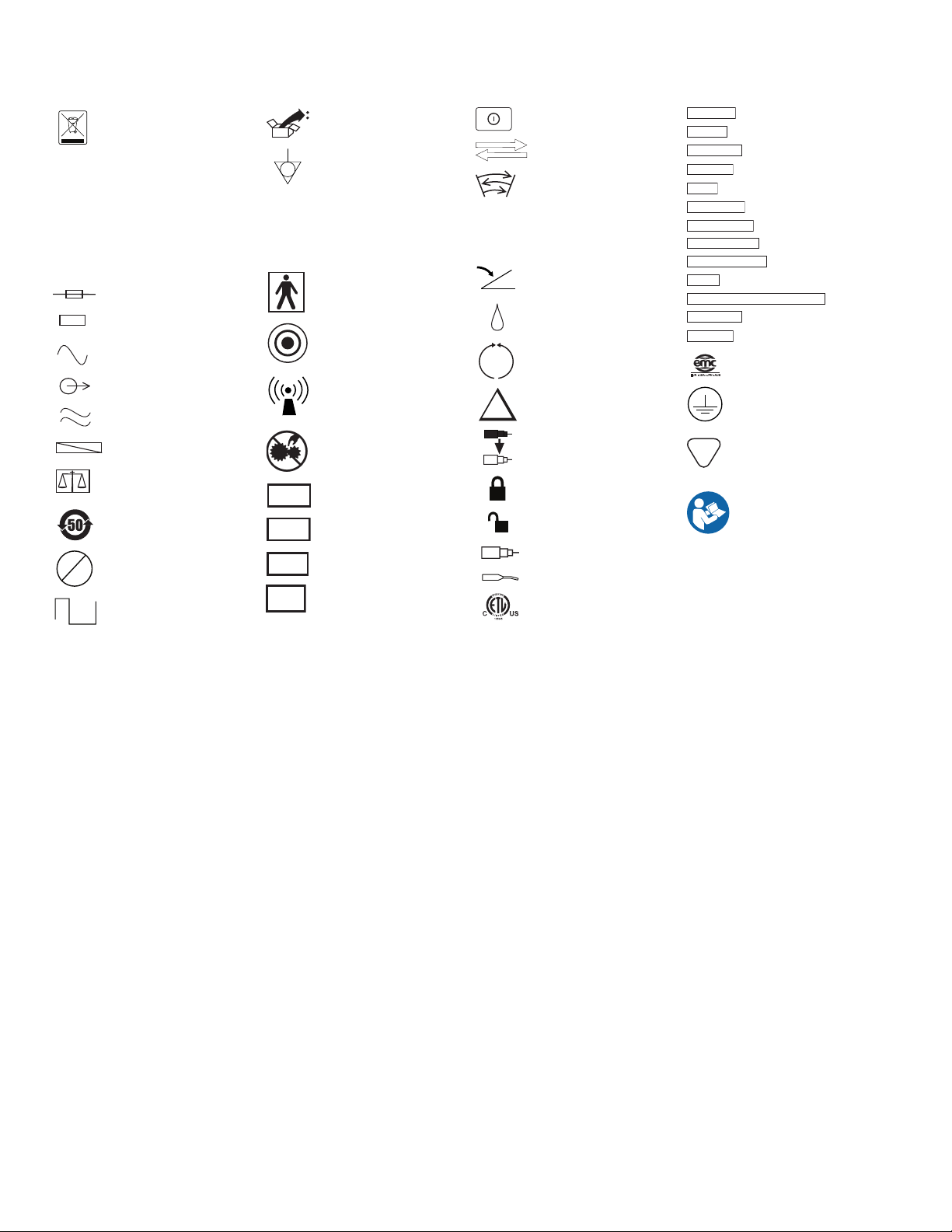
SYMBOLS
Accessory
Adapter
Attachment
Bone Mill
Brush
The following symbols can appear on this device and related packaging.
INTEGRATED POWER CONSOLE (IPC)
1
2
ACC
STERILE
>120 VAC
ON
OFF
<120s
>180s
Do Not Dispose Of This
Product In The Unsorted
Municipal Waste Stream.
Dispose Of This Product
Accordingto Local
Regulations. See Recycling.
Medtronic.Com For
Instructions On Proper
Disposal Of This Product.
Pump Head 1
Pump Head 2
Fuse
Accessory
AC Power
Output
Is Approximately Equal To
Non-Sterile
Quantity
RoHS - Environmental
Friendly Use Period - China
(SJ/T11364-2006)
Not Greater than 120vac
Applied Part Duty Cycle
IPX1
IPX7
BUR
NIM
EHS
Fr
Package Contents
Equaipotential Ground
Connector
Protected Against Vertical
Water Drops
Protected Against The Eects
Of Temporary Immersion
In Water
Type BF Applied Part
Start/Stop
RF Transmitter (Interference
May Occur)
Precaution: Pinch Hazard.
Keep Fingers Clear Of Rollers
Stim Bur Connector
NIM Console Connector
Electrical High Speed
Handpiece Connector
World Wide Standard for
Medical Tubing Diameter
On O Button
Use With
Oscillate
F
R
Forward
Reverse
Foot Pedal Connector
Fine Irrigant Adjustment
Left Foot Control Unit Button /
Mode Button
Right Foot Control Unit
Button / Control Button
Top Foot Control Unit Button /
Handpiece Button
Locked
Unlocked
Handpiece
Skeeter
Conforms to ANSI/AAMI ES
60601-1, IEC/EN 60601-1.
Certied to CSA C22.2
No.601.1
Control Unit
Dissecting Tool
Instrument Case
Lubricant/Diuser
Motor
Multi-Use Disposable Attachment
Refurbished
Regulator
EUR · USA · JPN · AUS
PHT
DEHP
EMC Compliance Mark
Protective Earth
Contains DEHP (di-2-ethyl
hexyl phthalate)
Follow Instructions For Use
GLOSSARY
The following words and acronyms may be used in this guide.
FCU Foot Control Unit
IPC Integrated Power Console
I.V. Intravenous
NIM Nerve Integrity Monitor - One or all of the Nerve Integrity Monitor units: NIM-Response 2.0, NIM-Neuro 2.0, NIM-Response 3.0
and NIM-Neuro 3.0
NIM-ECLIPSE Nerve Integrity Monitor for spinal surgeries
XPS Xomed Power System
FWD Forward - Rotation is clockwise
OSC Oscillate
REV Reverse - Rotation is counter-clockwise
CUSTOMER SERVICE
Medtronic Spinal and Biologics Business
Worldwide Headquarters
2600 Sofamor Danek Drive
Memphis, TN 38132
1800 Pyramid Place
Memphis, TN 38132
www.myspinetools.com
US Help Line
901-396-3133
800-876-3133
Customer Service: 800-933-2635
International Service
International Customers should contact their local Medtronic Xomed oce.
1-1
Page 6

INTEGRATED POWER CONSOLE (IPC)
INDICATIONS FOR USE
The IPC POWEREASE System is indicated for drilling, tapping and driving screws and working end attachments during spinal surgery, including
open and minimally invasive procedures. The IPC POWEREASE System is also used in the placement of screws, or cutting of screws, posts, and
rods.
The IPC is indicated for the incision/cutting, removal, drilling, and sawing of soft and hard tissue and bone, and biomaterials in Neurosurgical
(Cranial, Craniofacial), Orthopedic, Arthroscopic, Spinal, Sternotomy, and General surgical procedures.
DEVICE DESCRIPTION
The IPC POWEREASE System consists of a driver specically designed for drilling, tapping and driving screws in the pedicle during spinal surgery.
The driver is driven by the Integrated Powered Console (IPC) equipped with the appropriate software to operate the handpiece. The driver is
used to drive working end instruments capable of breaking setscrews, cutting posts, and cutting rods during spinal surgery.
The IPC POWEREASE System provides the power for tapping the pedicle and insertion of the pedicle screws is currently done manually using an
existing ratcheting handle which connects to the taps and drivers.
The POWEREASE Driver also has nerve stimulation capabilities when connected to the Medtronic NIM-Eclipse system. An external cable that
connects the NIM-Eclipse System to the driver enables the driver to have nerve stimulating capability.
The driver is equipped with a quick connect feature which allows for easy and secure attachment of working end instruments to perform the
various functions mentioned above.
CONTRAINDICATIONS
The IPC POWEREASE system is contraindicated for arthroscopic microdiscectomy in individuals with the following:
• Severe/progressive neurological decits
• Cauda equine syndrome
• Active infection
Arthroscopic microdiscectomy is not indicated for individuals with sequestered disc fragments, discogenic pain, internal disc destruction, or
lumbago.
WARNINGS
System Warnings
W1 It is important that the IPC system operator be familiar with the system User’s Guide, its precautions, procedures and safety issues.
W2 Do not use the IPC POWEREASE system in the presence of ammable anesthetics. Avoid potential ignition or explosion of gases.
W3 When not operating handpiece, eliminate accidental foot control activation. Control energy to and through the handpiece to prevent
unintended tissue, bone, or nerve resection.
W4 Disconnect power to the IPC system before cleaning the unit to avoid electrical macro shock.
W5 Do not attach unapproved components to the IPC system to avoid electrical macro shock.
W6 To avoid the risk of electrical shock, achieve electrical grounding reliability with proper connections. Connect the IPC system to hospital
grade receptacles only.
W7 This medical device complies with EN60601-1-2 safety standard for electromagnetic compatibility, requirements and test. However, if this
equipment is operated in the presence of high levels of electromagnetic interference (EMI) or highly sensitive equipment, interference may
be encountered and the user should take whatever steps are necessary to eliminate or reduce the source of the interference. Diminished
performance may lengthen operating time for anesthetized patient.
W8 Medical Electrical Equipment needs special Precautions regarding EMC and needs to be installed and put into service according to the EMC
information provided in this Guide.
W9 Portable and mobile RF communications equipment can aect Medical Electrical Equipment.
W10 Do not operate the IPC POWEREASE system in the presence of Magnetic Resonance Imaging devices.
W11 Use of accessories and cables other than those specied and sold by Medtronic may result in increased emissions and decreased immunity
of this unit.
W12 The IPC system should not be used adjacent to or stacked with other equipment. If adjacent or stacked use is necessary, the IPC system
should be observed to verify normal operation in the conguration in which it will be used.
W13 Do not attempt to run the IPC POWEREASE system handpiece immediately after autoclaving. Allow an adequate “cool down” period
(Typically 1 hour).
W14 Consult the Legend Bone Mill product insert before use with the Integrated Power Console system.
W15 For metal transection, observe the following safety precautions:
W15a Eye wear protection is essential.
W15b Irrigate well to cool the cutting surfaces.
W15c Protect the wound site from metal debris.
W15d Use a clamp or grasping device to control loose fragments during transection of any metal component.
W16 Do not operate the IPC POWEREASE system without eye protection.
W17 All service must be performed by Medtronic qualied personnel only.
W18 Repair and/or modication to the IPC system by anyone other than qualied service personnel may signicantly compromise the unit’s
ability to perform eectively and/or void the equipment warranty.
Component Warnings
W19 Do not use any parts other than Medtronic system components as damage or substandard performance could result.
W20 Always inspect the components before and after use for any damage. If damage is observed, do not use damaged part until it is repaired or
replaced. Damaged parts may deposit metal shavings on surgical site.
W21 When precise location of blade tip is required, engage the rotation lock on the handpiece, then calibrate and verify the blade tip on Image
1-2
Page 7

INTEGRATED POWER CONSOLE (IPC)
Guided Surgery (IGS) system. Always lock M4 handpiece when driving non-rotatable blades to maintain their IGS calibration.
W22 Employ visualization, including use of imaging techniques (e.g., uoroscopy, image guided surgery) when using rotating powered
accessories. Discontinue powered application in the event of lack of visualization of surgical site.
W23 Midas Rex Variable Exposure attachments. Surgeons should familiarize themselves with the performance of dissecting tools before use,
and should explore the eect of various levels of tool exposure on dissection stability. If the tool exhibits excessive chatter, vibration, or
movement, decrease the tool exposure.
W24 Motors and attachments may fail due to extended use and allow a component to detach and fall from the motor or attachment, causing
patient injury.
W25 Electrical contacts must be dry prior to use.
W26 Heavy side loads and/or long operating periods may cause the device to overheat.
W27 Do not use an overheated device, as it may cause thermal injury to the patient or operator.
W28 Use adequate irrigation. The use of a tool without irrigation may cause an inordinate amount of heat buildup resulting in a thermal injury
to tissue. Depending on the amount of irrigation used, the drill bits and saw blades can achieve temperatures in excess of 50°C.
W29 Do not attempt to change a dissecting tool, saw blade, or attachment while the motor is running, or when the motor or attachment is in an
overheated state.
W30 Do not immerse the system components, except as noted.
W31 Do not place motor, attachment and tool on the patient or in an unsecured location during surgery.
W32 A system that is not functioning properly should not be used until all necessary repairs have been made and the unit is tested to ensure
that it is functioning in accordance with Medtronic specications.
W33 Match the nomenclature and color code on the tool packaging to the same nomenclature and color code on the Attachment.
W34 Make sure that the attachment is still in the locked position after each adjustment of the tool exposure, as attempting to increase the tool
exposure too far, may result in the attachment accidentally being unlocked.
W35 Midas Rex Legend EHS Motor and Midas Rex Legend EHS Stylus Motor should only be operated when the attachment is in the locked
position.
W36 Smoke may be generated if attachment is not in the locked position.
W37 The Indigo and Legend EHS motors will not run properly unless the attachment is in the locked position.
W38 DO NOT change accessory with handpiece running to prevent laceration of user and cross-contamination through compromised glove.
W39 Remove Legend Footed Attachments cautiously and slowly as per instructions to avoid injury to the operator.
W40 DO NOT modify accessories used with the handpiece. Performance could be diminished with modied accessories.
W41 The safe use of the Endo-Scrub 2 System in procedures where surgical lasers are also employed has not been clinically demonstrated.
W42 In order to ensure compliance with requirements of IEC 60601-1, use a Medtronic approved power cable.
W43 To avoid the risk of electric shock, this equipment must only be connected to a supply main with protective earth.
W44 Keep NIM Muting Probe cable away from IPC system cables.
W45 Verify reusable device was sterilized prior to use. If not sterilized, do not use.
Disposable Warnings
W46 Tools are available for resection of soft tissue and bone for surgical procedures. Use of tools depends on the intended application and
patient needs. Sharp-cutting powered tools induce bleeding and removal of signicant tissue and bone.
W47 Use methods at the operative site to control bleeding that do not compromise patient safety during at-risk surgery.
W48 Always keep the cutting area of the tool/saw blade away from ngers and loose clothing. Prevent laceration of user and cross-
contamination through compromised glove.
W49 Operate the tool only after the appropriate anatomical landmarks and the intended surgical site have been conrmed.
W50 Use care in application of the moving cutting end to only appropriate anatomical landmarks and the intended surgical site when using
powered accessories.
W51 Insertion of metal objects in accessory tip may cause the accessory to break leaving fragments in the wound. The fragments may be
dicult to remove, causing irritation, inammation and foreign-body response at surgical site.
W52 Bending or prying may break the accessory, causing harm to patient or sta.
W53 Do not use excessive force to pry or push bone with the attachment, tool or blade during dissection.
W54 A tool’s size and geometry may create excessive vibration at certain speeds. Increase or decrease speed on console. Change to a new tool
to prevent unintended tissue removal from patient.
W55 Test for wobble at desired speed prior to use. Discontinue use of accessory if tip begins to wobble and replace accessory to prevent
unintended tissue removal from patient.
W56 Eccentricity of the tool can cause tool vibration and may result in excess tissue and bone destruction and hearing damage.
W57 Excessive noise from the tool when drilling close to the cochlea or ossicular chain may cause hearing damage.
W58 CONSULT the cranial perforator device labeling for the recommended speed specications.
W59 Tools with “L” identication are longer tools intended for light bone dissection. The increased tool head/stem conguration may aect
dissection stability.
W60 Tool utes and blade teeth are sharp and may perforate surgical gloves. Tools/blades may be grasped with a hemostat to aid in installation
and removal.
W61 DO NOT attempt to resharpen used tools. Worn tools should be replaced with new ones frequently to ensure eective cutting and control.
W62 Carefully inspect tool both prior to and following each use for signs of excessive wear, fragmentation, eccentricities or other defects.
Replace any suspicious tools with a new one prior to use.
W63 Excessive pressure applied to bur may cause bur fracture. Should a tool fracture in use, extreme care must be exercised to ensure that all
fragments of the tool are retrieved and removed from the patient. Unremoved tool fragments may cause tissue damage to the patient.
W64 Do not use metal-cutting tools on bone.
W65 Use only rotary tools specically designed for use with this drill system.
W66 When using non-rotatable tools, ensure rotation lock is engaged to prevent inadvertent rotation.
1-3
Page 8

INTEGRATED POWER CONSOLE (IPC)
W67 The use of powered reciprocating instruments may result in vibration / related injury.
W68 Powered blades should be operated in the oscillate mode only. Operating in the forward mode may cause damage to the blade.
W69 Do not attempt to sterilize disposable devices. The disposables are packed sterile and are not intended for repeat use. To prevent
contamination, use only once.
W70 Any tubing or other tip protectors used during shipping must be removed prior to cleaning and sterilization.
W71 Do not use accessory if package is opened or damaged. Broken seal oers no protection against cross-contamination.
W72 Properly dispose of single-use devices removed from sterile packages. Devices lose sterility upon removal from packaging.
W73 Do not use dull, damaged or bent tools. Use of dull tools can reduce handpiece eectiveness and cause the handpiece temperature to
increase.
W74 T&A Blades: Gently remove the inner tube from the outer tube. The inner tube may elongate upon removal from the outer tube. If this
occurs, the inner tube may not lock properly into the handpiece or the blade may not work properly.
W75 T&A Blades: Rotate the inner tube when removing and inserting it in the outer tubes to prevent damage to the internal seal. If the seal is
damaged, the blade will leak at the handpiece.
W76 Always ensure that the drill is securely engaged into the handpiece prior to operating the system.
W77 Always examine operation of each tool in a handpiece before use.
W78 Powered burs and drills should be operated in the forward mode only.
W79 This system requires insulated connectors for the StraightShot M4 Microdebrider, StraightShot Magnum II Microdebrider, StraightShot III
Microdebrider, Midas Rex SC1, Visao, or Skeeter handpieces and the Multi Function Foot Control Unit.
W80 Sterilize and dry reusable device before storing the system. Decrease likelihood of cross-contamination with timely sterilization.
W81 After each procedure, properly clean all reusable system components.
W82 Auxiliary Power Outlet with protective cover is for use with the Hydrodebrider or Bone Mill consoles only.
W83 Place Stylus Touch in safe mode while not in use.
W84 Do not place Stylus Touch handpiece in the proximity of magnetic eld, such as magnetic drape and MRI equipment, to avoid inadvertent
handpiece activation.
W85 Do not apply excessive side loading. Excessive side loading could cause angled attachments to unlock accidentally from motor.
PRECAUTIONS
P1 PRIME/FLUSH Priming is a feature designed to purge air out of the tubing set(s) during setup. The rst time a Prime or Flush button is
pressed it will turn on pump 1 and/or 2 long enough to purge air out of the tubing set(s). Turning power O and On resets the PRIME
feature. Once pressed all Prime buttons will change to Flush buttons.
P2 To prevent damage to curved tools, disconnect suction tube prior to changing tool during procedure.
P3 When using an angled attachment, hold the handpiece assembly by the attachment so that the attachment does not inadvertently loosen
from the handpiece.
P4 For Legend tools only:
If a tool package is opened, but the tool is not used or contaminated, the tool can be re-sterilized. Remove tool from original packaging
and place into an approved autoclave package. Steam sterilize as follows:
High-Vacuum Steam 132°C for 5 minutes
Gravity Displacement 132°C for 15 minutes
The re-sterilized tool must be used promptly following re-sterilization. If rust or corrosion is encountered after re-sterilization, do not use
the re-sterilized tool.
P5 DO NOT run the 16-MF attachment with operating speed above 62,000 rpm. This may cause over heating and damage to internal gears of
attachment.
P6 DO NOT use twist drill or Contra-Angle tool at an operating speed over 62,000 rpm.
P7 Do not attempt to disconnect the cable from the Midas Rex Legend EHS Stylus Motor.
P8 Do not kink cables. Inspect cables and pins for cracks, tears or corrosion.
P9 Do not use anti-fog on scope or sheath, as weeping or leaking may result.
P10 Disconnect cable from Midas Rex Legend EHS motor prior to sterilization.
P11 The use of a washer-disinfector for cleaning may cause a pre-mature degradation in performance.
P12 Remove devices from instrument case before placing into washer disinfector and allow devices to drain.
P13 Orient devices in the washer-disinfector by following manufacturer recommendations.
P14 DO NOT use low-temperature hydrogen peroxide gas plasma sterilization due to the lumen internal diameter and length restrictions.
P15 DO NOT use low-temperature liquid peracetic acid sterilization due to immersion procedure.
P16 DO NOT steam or EO sterilize the Legend Attachment Cleaning Nozzle.
P17 Remove and discard accessories following local regulations for proper disposal of contaminated materials.
P18 Disposable devices are for single-use only.
P19 Clean the motor and cable while still connected together. This will help to reduce ingress of debris.
P20 Use ONLY recommended cleaning agents.
P21 Do not use excessive force to insert the endoscope into the Endo-Scrub 2 sheath. This will damage the endoscope as well as the Endo-
Scrub 2 sheath.
P22 If the endoscope tip can be seen extending beyond the tip of the Endo-Scrub 2 sheath, then the sheath has been damaged. Damaged
product must be immediately discarded.
1-4
Page 9

INTEGRATED POWER CONSOLE (IPC)
SYSTEM REQUIREMENTS AND SPECIFICATIONS
Console Specications
Functional Standards for Electrical Systems
ANSI/AAMI ES60601-1 Medical electrical equipment - Part 1: General requirements for basic safety and essential performance 2005
IEC 60601-1 Medical electrical equipment - Part 1: General requirements for basic safety and essential performance 2005
EN 60601-1 Medical electrical equipment - Part 1: General requirements for basic safety and essential performance
(IEC 60601-1:2005)
IEC 60601-1-4 Medical electrical equipment - Part 1: General Requirements for Safety, Part 4: Programmable Electrical Medical Systems 2000
EN 60601-1-2 Medical electrical equipment - Part 1-2: General Requirements for Safety - Collateral Standard: Electromagnetic
Compatibility - Requirements and Tests
CSA-C22.2 No. 601.1 Medical Electrical Equipment - Part 1: General Requirements for Safety 2005
Physical Dimensions
Size 277 mm W x 353 mm H x 267 mm D
Weight 7.3 kg
Operational Environment
Temperature +10°C to +33°C
Humidity 30% to 75% RH
Barometric Pressure 700 - 1060 hPa
Transport and Storage Environment
Temperature -40°C to +70°C
Humidity 10% to 95% RH
Barometric Pressure 500 to 1060 hPa
Display / Touchscreen
Type High contrast, digital, graphic color, visible in complete darkness
Resolution Display 21 cm diagonal, resolution 480 X 640 pixels
Audio Output
Baseline Audio Sound Level 60 dBA minimum SPL (1 m)
Electrical
Input Voltage 100 V-240 V ± 10%
Frequency 50/60 Hz
Power Consumption 500 VA
Auxiliary AC output 200 VA Max.
Internal Fuse 5 x 20 mm T. L. 5 A, 250 V
Medtronic Xomed P/N 11270066
Duty Cycle for Applied Part Maximum On Time 120 Seconds
Minimum O Time 180 Seconds
Power Cord Product Numbers
2006
2001/
A1: 2006
North America:
USA, Barbados, Belize, Bolivia, Canada,
Columbia, Ecuador, Venezuela
Standard P/N EA600 or 1895820
6 meter P/N EA650 or 189721
China
P/N EA604
Argentina
P/N EA608
Australia, New Zealand
P/N EA605
United Kingdom,
Ireland, Hong Kong, Malaysia, Singapore
P/N EA606 or 1895821
India, South Africa
P/N EA607
Israel
P/N EA609
Japan
P/N EA603 or 1895823
Continental Europe:
Austria, Belgium, Finland, France, Germany,
Greece, Korea, Luxembourg, Netherlands,
Norway, Portugal, Spain, Sweden
P/N EA602 or 1895822
Switzerland
P/N EA601
Denmark
P/N EA610
Italy, Chile
P/N EA611
1-5
Page 10
INTEGRATED POWER CONSOLE (IPC)
(5)
(5)
(1)
(3)
(4)
(2)
SYSTEM SOUNDS AND FIGURES
Audible Alarms and Tones
The following alarms and tones can sound while using the IPC Console.
Audible Alarm
When the system detects an error, a message appears on the touchscreen and the system emits a sequence of three tones.
Audible Tones
IPC Tone Cause(s)
1 Tone • Conrmation of change button pressed.
• Change from forward to oscillate.
• Change of active handpiece.
2 Tones Change from oscillate to forward.
3 Tones • Audible Alarm. Error detected. See screen for error message.
• Active handpiece is in reverse and foot pedal pressed.
• First time accessory changes from forward to reverse.
Long Tone Change from handpiece to drill.
System Figures
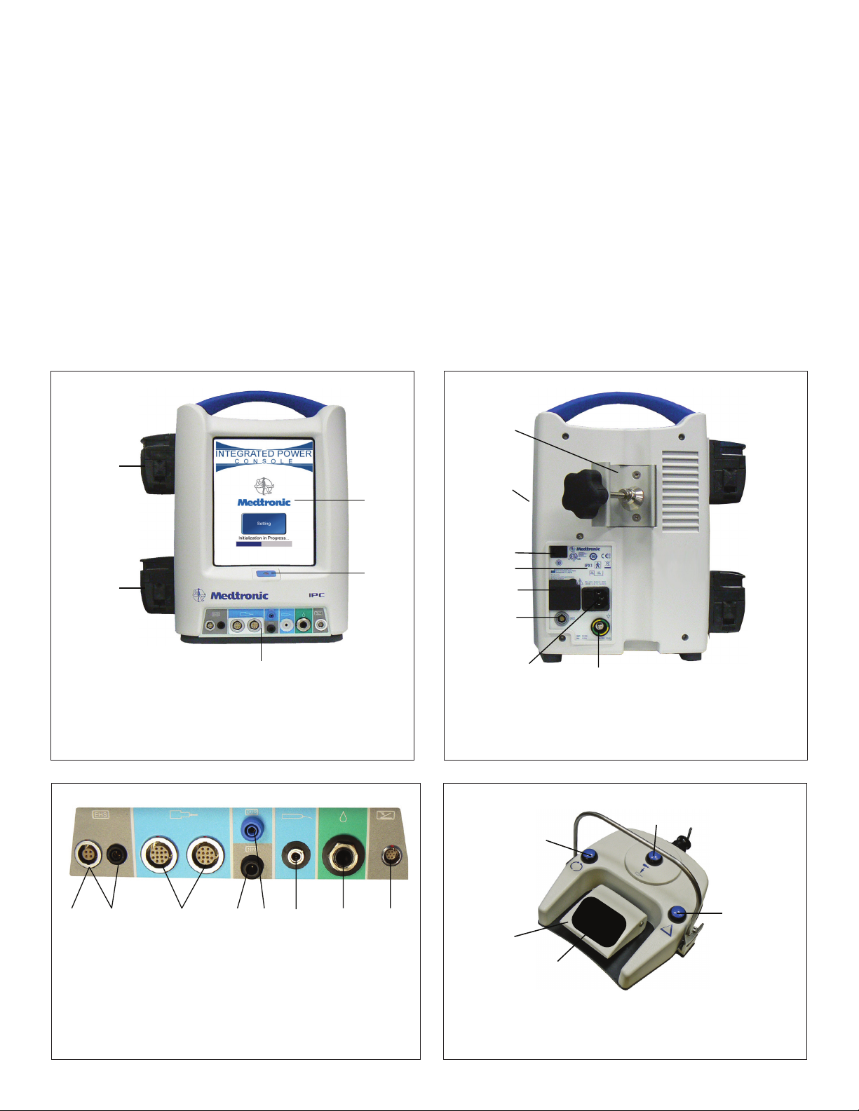
Figure 1-1. IPC Console Front
1 Pump 1: Coolant, lense cleaning or
irrgation
2 Pump 2: Irrigation or lense cleaning
3 Console Connector Panel for peripheral
devices
4 Power On/O
5 Touchscreen
Figure 1-2. IPC Console Back
(1)
(2)
(3)
(4)
(5)
(6)
(7)
1 Pole Clamp
2 Compact Flash Card Port (Medtronic Use)
3 Manual Start/Stop
4 Fuse Access
5 Auxiliary Power Outlet
(8)
6 Endo-Scrub 2 Connector
7 Hospital Grade Power Cord Connector
8 Equipotential. Apply potential equalization
conductor.
Figure 1-3. IPC Console Connector Panel
(1) (2) (3) (4) (5) (6) (7) (8)
1 Legend EHS Motor
2 Legend EHS Stylus Motor
3 Spine Shaver Handpiece
StraightShot M4
Microdebrider
StraightShot Magnum II
Microdebrider
StraightShot III
Microdebrider
Stylus Touch Motor
Visao Drill
Indigo Drill
Midas Rex Microsaws
Triton Drill
4 Stimulus input from
Patient Interface (NIM or
NIM-Eclipse)
5 Stimulus output to Stim
Bur Guard or POWEREASE
6 Skeeter Handpiece
7 Endo-Scrub 2 Finger
Switch
Endo-Scrub 2 Footpedal
Intelliow Irrigation
Remote Control
8 Multifunction Footpedal
1-6
Figure 1-4. Multifunction Footpedal
(1)
(2)
(3)
1 Mode Button
2 Foot Pedal
3 Slip-resistant Foot Pad
4 Control Button
5 Handpiece Button
(4)
Page 11
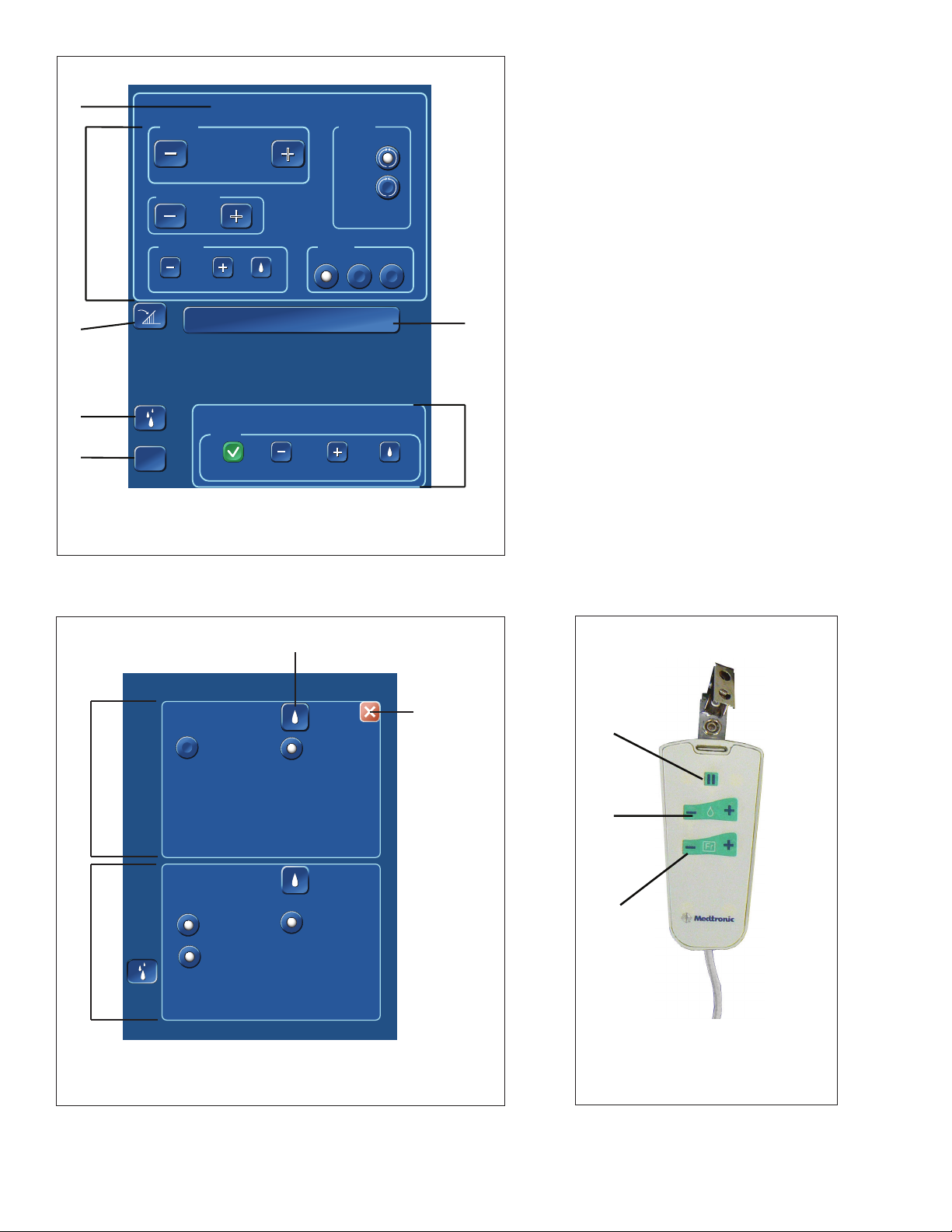
Figure1-5. IPC Touchscreen
(1)
INTEGRATED POWER CONSOLE (IPC)
(1)
Speed
(2)
Acceleration
Irrigation
(3)
(4)
Pumps
(5)
1 Displays Active Accessory
2 Accessory Control Panel
3 Footpedal Variable Control
4 Opens Pumps Screen
Help
?
?
Accessory Name
60000
RPM
100
+
+
%
+
+
0
cc/min
Flow
Prime
(Handpiece Name)
EndoScrub 2
Flow
Mode
+
+
Setting
5 Opens Help Screen
6 Irrigation Accessory Panel
7 Inactive Handpiece
Finger
3
Control
+
+
FWD
REV
Foot
Both
PrimeOn
(7)
(6)
Figure 1-6. IPC Pumps Screen
Pump 1
None
None
(3)
Pump 2
None
(4)
1 Prime/Flush Pump
2 Close Pumps panel
3 Pump 1 Panel Available Accessories
4 Pump 2 Panel Available Accessories
None
M4
M4
Irrigation
Irrigation
Prime
Prime
Endo-Scrub® 2
Endo-Scrub® 2
Prime
Endo-Scrub® 2
Endo-Scrub® 2
Figure 1-7. IntelliFlow Remote Control
(2)
(1)
(2)
(3)
1 Pause/On-O
2 Increase/Decrease Fine Adjustment
3 Increase/Decrease Coarse Adjustment
OR Select Stainless Steel Tubing Size
(French Size) for Suction Irrigatior
1-7
Page 12
INTEGRATED POWER CONSOLE (IPC)
PREOPERATING INSTRUCTIONS
The following are general IPC pre-operating instructions. “Accessories or Additional Devices Operating Instructions” contains individual accessory
operating instructions.
When the System Arrives
• Verify the contents of the box match the packing slip. If incomplete or damaged, notify Medtronic Customer Service.
• If container is damaged, or cushioning material shows stress, notify carrier and Medtronic Customer Service. Keep shipping materials for
carrier inspection.
• Save the cartons and packing material. If the instrument is to be shipped the shipping package will provide proper protection.
Set up the IPC
Refer to the related topics for detailed instruction.
1. Install pump cartridges or irrigation tubing.
2. Prepare IPC for use.
3. Calibrate touchscreen, if necessary.
4. Change system settings, if necessary.
5. Set up and prime pumps.
6. Conrm system operation.
7. Press the manual start/stop button on the back of the console (Figure 1-2) and verify you can start/stop the handpiece, irrigiation and/or
coolant ow.
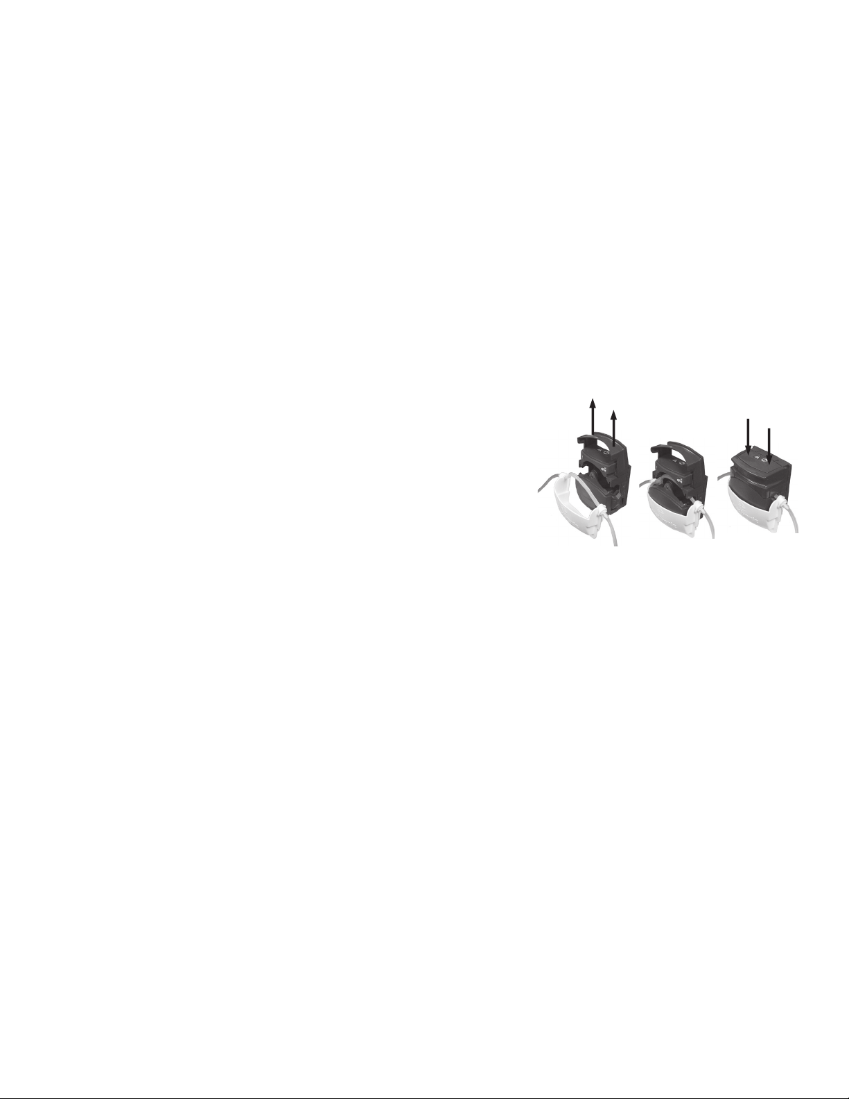
Install the Pump Cartridges or Irrigation Tubing
1. Locate the correct pump and lift up the lock (Figure 1-8).
Pump 1: Coolant, lens cleaning or irrgation
Pump 2: Irrigation
Important: The number on the pump must match the number on the cartridge (either
1/1 or 2/2). If the cartridge does not have a pump designator number, use the Pump
Setup Screen to install the pump cartridge.
2. Insert the pump cartridge.
3. Snap the pump lock shut.
Warning: Ensure the pump cartridge does not crimp the tubing.
Prepare IPC for Use
1. Verify the wheels are locked on the IPC cart.
2. Inspect all components for damage and determine if the system is ready for use.
3. Mount the IPC and irrigation/coolant bags on the IV pole.
Important: Mount irrigant and coolant bags above the IPC to ensure adequate ow.
4. Plug the IPC into the power source. Position the IPC so that it does not obstruct the power source for the purpose of disconnecting the
Main voltage by the power cord.
5. Locate the correct footpedal or accessory connection port on the connector panel (Figure 1-3) and insert the connector.
Note: To insert multi-pin connectors (indicated by a silver or red mark on the connector), align the mark on the connector to the mark on
the console, then insert the connector.
6. Connect suction, cooling and/or irrigation tubing.
7. Turn on the IPC and verify the system passes the self-test.
Note: If the IPC does not detect a handpiece, footpedal, or Endo-Scrub connection, the Connect Handpiece/Connect Footswitch screen
appears. Do one or all of the following:
• Verify the cable is connected to the correct connection port.
• Press [OK] in the Connect Footswitch or Endo-Scrub 2 message window to continue use of the IPC without the footpedal or Endo-
Scrub 2.
Calibrate Touchscreen
Note: This step is optional.
1. Turn on the IPC console.
2. While the system starts, on the Splash screen, press [Settings].
3. On the Settings screen, press Touch Screen Calibration and follow the screen prompts.
Figure 1-8. Install Pump Cartridge
1
2
3
Change System Settings
Note: During surgery, system settings can be overwritten.
1. Turn on the IPC console.
2. While the system starts, on the Splash screen, press [Settings].
3. To change the language, press the appropriate language.
4. To change the default settings, press [Default].
• On the Default screen, press the forward or backward arrow to change the accessory.
• Make changes to the default settings.
• To conrm system settings and return to the Splash screen, press [OK].
5. To conrm system settings and continue to the IPC touchscreen, press [OK].
Handpiece Default Settings
The system conguration is dependent on the handpiece(s) connected to the console. The following table denes the default congurations,
1-8
Page 13

INTEGRATED POWER CONSOLE (IPC)
default settings (X) and default options (O).
Table 1. IPC Touchscreen Default Congurations
Speed Mode or Mode Select Switch
Handpiece rpm cpm % Forward Oscillate Reverse Acceleration Size Flow Irrigation Control
Visao 80000 X O 30
Indigo 60000 X O 30
Midas Rex SC1 3400 O X 60
StraightShot M4 5000 O X 30
StraightShot III, Magnum II 5000 O X 30
Legend EHS Stylus 60000 X O 45% 0
Legend EHS 70000 X O 0
Stylus Touch 60000 X O 100% 0 Finger
Skeeter 16000 X O 0
Endo-Scrub 2 3
Suction Irrigator 8 50%
Triton 100 X
100 X
Midas Rex Microsaws 100 0
Powerease 120 X
250 X
120 X
Set up and Prime Pumps
• The IPC turns on pump 1 and/or 2 long enough to purge air out of the tubing set(s) the rst time the prime button is pressed.
• The IPC resets the prime feature when you turn IPC power O and On.
• After you prime the pump, the prime button and functionality become ush functionality.
1. Connect tubing from an IPC cartridge to irrigation or coolant tubing on an accessory.
2. On the irrigation tubing, turn the clamp to OPEN.
3. If an accessory uses the clear drip chamber (Visao), ll the clear drip chamber with coolant. To ll, squeeze and release the chamber until
full.
4. On the IPC touchscreen (Figure 1-5), press the pumps button.
5. On the IPC pumps screen (Figure 1-6), select the accessory for each pump.
6. For each pump, press the prime button and verify the following:
• Pump(s) run until air is completely purged from tubing.
• Small amount of lubricate ows at the tip of the irrigation device.
• Pump(s) turns o.
7. Press the close button.
Pump Default Congurations
The pump conguration is dependent on the handpiece(s) connected to the console. The following table denes the pump default settings (X)
and default options (O).
Table 2. IPC Pumps Screen Default Congurations
Pump 1 Pump 2 Endo-Scrub 2 Suction Irrigator
Handpiece Cooling Irrigation Irrigation Pump 1 Pump 2 Pump 1 Pump 2
Visao X X O O
Indigo O X O O O O
Midas Rex SC1 O X O O
StraightShot M4 O X* X O
StraightShot III, Magum II O X* X O
Legend EHS Stylus X O* O O O O
Legend EHS X O O O O O
Stylus Touch X O O O O O
Skeeter O O O O
1-9
Page 14
INTEGRATED POWER CONSOLE (IPC)
Table 2. IPC Pumps Screen Default Congurations
Endo-Scrub 2 X O X O
Suction Irrigator O O O O
Midas Rex Microsaws O X O O O O
Powerease O O O O
O O O O
O O O O
* When the IPC detects both the Straightshot M4 and the Legend EHS Stylus Touch handpiece, by default, the system sets pump 2 as a “shared”
irrigation pump. You must manually connect the irrigation tubing to the active handpiece.
Conrm System Operation
1. Conrm the irrigation pedal starts handpiece and irrigation ow. Verify the speed changes from white to yellow in the Speed box on the
touchscreen.
2. Conrm the footpedal buttons operate. Refer to “Operate Multifunction Footpedal” for details.
3. On the touchscreen, verify you can do all of the following:
+
• Adjust Speed: In the Speed box, press the plus and minus buttons.
• Change Modes: In a Mode box, press any mode button.
• Adjust Flow Rate: In the Irrigation box, press the plus and minus buttons.
+
+
+
IPC COMPONENTS
Multifunction Footpedal
You can use the multifunction footpedal (Figure 1-4) to start/stop the handpiece, control handpiece speed, handpiece selection and mode of
operation. Refer to the Multifunction Footpedal Controls topic for each handpiece for specic use and control.
Multifunction Footpedal Failure
Use the manual start/stop button (Figure 1-2) on the back of the IPC Console to operate the handpiece if the multifunction footpedal fails during
a procedure.
IntelliFlow Irrigation Remote Control
Use the IntelliFlow irrigation remote control (Figure 1-7) to start/stop and change irrigation ow while in the sterile eld.
If you are using handpiece irrigation:
• To pause irrigation ow, press the Pause/On-O button.
• To adjust ow rate, press the Fine Adjustment or Coarse Adjustment Increase/Decrease button.
If you are using the Suction Irrigator:
• To pause or turn on/o the Suction Irrigator, press the Pause/On-O button.
• To adjust ow rate, press the Fine Adjustment Increase/Decrease button.
• To select the stainless steel tubing size (French size), press the Stainless Steel Tubing Size button.
Auxillary Power to Console
Warning: The auxillary power outlet is available for use with the Hydrodebrider and Bone Mill IPC consoles only (see W 82).
The auxillary power outlet is for use at grid voltage ≤120 VAC only.
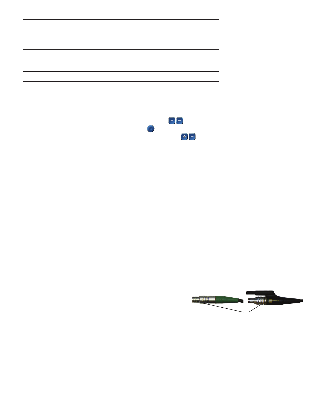
POSTOPERATIVE INSTRUCTIONS
Disconnect Accessory Cable from Console
To disconnect non-sillicone multi-pin cables from the console, push the cable towards
the console and then pull out by the lock ring.
Note: Silicone insulated multi-pin and single pin cable connectors do not have a lock
ring (1). Remove these types of cable connectors straight from the connector panel.
Warning: After disconnecting insulated connectors (see W79) from the console,
connectors that have debris under the insulator must be cleaned according to
Cleaning and Sterilization instructions. If debris is still present after cleaning and
sterilization, return for warranty servicing.
Clean the Multifunction Footpedal
Important: If debris is present under the footpedal’s boot, return for warranty service.
DO NOT immerse or sterilize the footpedal.
DO NOT use alcohol, other solvents or abrasive cleaners.
1. On the slip resistant foot pad ONLY, spray a neutral enzymatic detergent, pH 6.0-8.0, or a phenol based disinfectant, mixed according to
manufacturer’s instructions.
2. Leave the solution on the foot pad for approximately 10 minutes.
3. Dampen a cloth with a neutral enzymatic detergent, pH 6.0-8.0, or a phenol based disinfectant, mixed according to manufacturer’s
instructions.
4. Wipe the footpedal with the damp cloth until visually clean.
5. Dry the unit with a clean, non-abrasive cloth.
1-10
1
Page 15

INTEGRATED POWER CONSOLE (IPC)
GUIDANCE AND MANUFACTURER’S DECLARATION ELECTROMAGNETIC IMMUNITY
Part I
The IPC is intended for use in the electromagnetic environment specied below. The customer or the user of the IPC should assure that it is used in such
Immunity test
Electrostatic discharge (ESD) ±6kV contact ±6kV contact
IEC 61000-4-2 ±8kV air ±8kV air
Electrical fast transient/burst
IEC 61000-4-4
Surge
IEC 61000-4-5
Voltage dips, short interruptions and voltage variations on
power supply input lines
IEC 61000-4-11
Power frequency (50/60 Hz)
magnetic eld
IEC 61000-4-8
Note: UT is the a.c. mains voltage prior to application of the test level.
The IPC is intended for use in the electromagnetic environment specied below. The customer or the user of the IPC should assure that it is used in such an envi-
Emissions test Compliance Electromagnetic environment - guidance
RF emissions
CISPR 11
RF emissions
CISPR 11
Harmonic emissions
IEC 61000-3-2
Voltage uctuations
IEC 61000-3-3
Guidance and manufacturer’s declaration – electromagnetic immunity – Part I
IEC/EN60601-1-2
test level
±2kV for power supply lines
±1kV for input/output lines
±1kV dierential mode
±2 kV common mode
<5 % UT (>95 % dip in UT)
for 0.5 cycle
40 % UT (60 % dip in UT) for
5 cycles
70 %UT (30 % dip in UT) for
25 cycles
<5 % UT (>95 % dip in UT)
for 5 sec
3 A/m 3 A/m
Guidance and manufacturer’s declaration – electromagnetic emissions
Group 1
Class A
Class A
Complies
±2kV for power supply lines
±1kV for input/output lines
±1kV dierential mode
±2kV common mode
<5 % UT (>95 % dip in UT)
for 0.5 cycle
40 % UT (60 % dip in UT) for
5 cycles
70 % UT (30 % dip in UT) for
25 cycles
<5 % UT (>95 % dip in UT)
for 5 sec
an environment.
Compliance level Electromagnetic environment - guidance
Floors should be wood, concrete, or ceramic tile. If oors are covered
with synthetic material, the relative humidity should be at least 30 %.
Mains power quality should be that of a typical commercial or hospital environment.
Mains power quality should be that of a typical commercial or hospital environment.
Mains power quality should be that of a typical commercial or hospital environment. If the user of the IPC requires continuous operation
during power mains interruptions, it is recommended that the IPC be
powered from an uninterruptible power supply or a battery.
Power frequency magnetic elds should be at levels characteristic of
a typical location in a typical commercial or hospital environment.
ronment.
The IPC uses RF energy only for its internal function. Therefore, its RF emissions are very
low and are not likely to cause any interference in nearby electronic equipment
The IPC is suitable for use in all establishments, other than domestic and those directly
connected to the public low-voltage power supply network that supplies buildings for
domestic purpose.
Recommended separation distances between portable and mobile RF communications equipment and the IPC
The IPC is intended for use in the electromagnetic environment in which radiated RF disturbances are controlled. The customer or the user of the IPC can help
prevent electromagnetic interference by maintaining a minimum distance between portable and mobile RF communications equipment (transmitters) and the
IPC as recommended below, according to the maximum output power of the communications equipment.
Rated maximum power
of transmitter
W
0.01 0.12 0.12 0.23
0.10 0.38 0.38 0.73
1.00 1.20 1.20 2.30
10.00 3.80 3.80 7.30
100.00 12.00 12.00 23.0
For transmitters rated at a maximum output power not listed above, the recommended separation distance d in meters (m) can be estimated using the equation applicable to the frequency of the transmitter, where P is the maximum output power rating of the transmitter in watts (W) according to the transmitter
manufacturer.
NOTE 1 At 80 MHz and 800 MHz, the separation distance for the higher frequency range applies.
NOTE 2 These guidelines may not apply in all situations. Electromagnetic propagation is aected by absorption and reection from structures, objects and
people.
150 kHz to 80 MHz
d = 1.2√P
Separation distance according to frequency of transmitter meters
80 MHz to 800 MHz
d = 1.2√P
800 MHz to 2.5 GHz
d = 2.3√P
1-11
Page 16

INTEGRATED POWER CONSOLE (IPC)
Part II
The IPC is intended for use in the electromagnetic environment specied below.
The customer or the user of the IPC should assure that it is used in such an environment.
Immunity test IEC/EN60601-1-2 test
level
Conducted RF 3Vrms 3Vrms d = 1.2√P
IEC 61000-4-6 150kHz to 80MHz
Radiated RF 3V / m 3V / m d = 1.2√P 80MHz to 800MHz
IEC 61000-4-3 80MHz to 2.5GHz d = 2.3√P 800MHz to 2.5GHz
Compliance level Electromagnetic environment - guidance
Portable and mobile RF communications equipment should be used no closer to
any part of the IPC , including cables, than the recommended separation distance
calculated from the equation applicable to the frequency of the transmitter.
Recommended separation distance
Where P is the maximum output power rating of the transmitter in watts (W)
according to the transmitter manufacturer and d is the recommended separation
distance in meters (m).
Field strengths from xed RF transmitters, as determined by an electromagnetic
site survey,a should be less than the compliance level in each frequency range.b
Interference may occur in the vicinity of equipment marked with the following
symbol:
NOTE 1 At 80 MHz and 800 MHz, the higher frequency range applies.
NOTE 2 These guidelines may not apply in all situations. Electromagnetic propagation is aected by absorption and reection from structures, objects and
people.
NOTE 3 When operating the IPC with Stylus Touch, the compliance level is 3 V/m except from 88 MHz to 91 MHz where it is 1 V/m. The formula for separation
distance for the IPC with Stylus Touch will be d = 3.5 √P in that frequency range.
a Field strengths from xed transmitters, such as base stations for radio (cellular/cordless) telephones and land mobile radios, amateur radio, AM and FM radio
broadcast and TV broadcast cannot be predicted theoretically with accuracy. To assess the electromagnetic environment due to xed RF transmitters, an
electromagnetic site survey should be considered. If the measured eld strength in the location in which the IPC is used exceeds the applicable RF compliance level above, the IPC should be observed to verify normal operation. If abnormal performance is observed, additional measures may be necessary, such
as re-orienting or relocating the IPC .
b Over the frequency range 150 kHz to 80 MHz, eld strengths should be less than 3 V/m.
1-12
Page 17

INTEGRATED POWER CONSOLE (IPC)
LIMITED WARRANTY
A. This Limited Warranty provides the following assurance for the customer who purchases a Medtronic IPC System. This Limited Warranty is ex-
tended only to the buyer purchasing the IPC System directly from Medtronic or from its aliate or its authorized distributor or representative.
The IPC System includes the console, motor or handpiece, foot control, motor cables, instrumentation cases and trays (hereafter referred to
as System Components), straight and angled motor attachments (hereinafter referred to as “Attachments”), bur guards and telescoping tubes
(hereinafter referred to as Semi-reusable Components) and dissecting tools, irrigation and coolant tubing, and Intelliow remote control (hereinafter referred to as Single Use Components) and jointly referred to as the IPC System, unless specically noted.
i. Should a System Component fail to function to Medtronic’s published specications during the term of this Limited Warranty (one year
from the date of sale of a new System Component or 90 days from the date of sale of a refurbished or used System Component), Medtronic
will either repair or replace the Motor Component or any portion thereof.
ii. Should an Attachment fail to function to Medtronic’s published specications during the term of this Limited Warranty (90 days from the
date of sale of a new Attachment), Medtronic will either repair or replace the Attachment or any portion thereof.
iii. Should a Semi-reusable Component fail to function to Medtronic’s published specications during the term of this Limited Warranty (30
days from the date of sale of a new Semi-reusable Component), Medtronic will replace the Semi-reusable Component or any portion
thereof.
iv. Should a Single Use Component fail to function to Medtronic’s published specications prior to its “use by” date Medtronic will replace the
Single Use Component.
B. To qualify for this Limited Warranty, the following conditions must be met:
i. The Product must be used on or before its “Use By” or “Use Before” date, if applicable.
ii. The Product must be used in accordance with its labeling and may not be altered or subjected to misuse, abuse, accident or improper
handling.
iii. Medtronic must be notied in writing within thirty (30) days following discovery of a defect.
iv. The Product must be returned to Medtronic within thirty (30) days of Medtronic receiving notice as provided for in (3) above.
v. Upon examination of the Product by Medtronic, Medtronic shall have determined that: (i) the Product was not repaired or altered by any-
one other than Medtronic or its authorized representative, (ii) the Product was not operated under conditions other than normal use, and
(iii) the prescribed periodic maintenance and services, if applicable, have been performed on the Product.
C. This Limited Warranty is limited to its express terms. THIS LIMITED WARRANTY IS IN LIEU OF ALL OTHER WARRANTIES, EXPRESSED OR IMPLIED
WHETHER STATUTORY OR OTHERWISE, INCLUDING ANY IMPLIED WARRANTY OF MERCHANTABILITY OR FITNESS FOR A PARTICULAR PURPOSE.
In no event shall Medtronic be liable for any consequential, incidental, prospective or other similar damage resulting from a defect, failure, or
malfunction of the IPC System, whether a claim for such damage is based upon the warranty, contract, negligence or otherwise.
D. The exclusions and limitations set out above are not intended to, and should not be construed so as to, contravene mandatory provisions of
applicable law. Users may benet from statutory warranty rights under legislation governing the sale of consumer goods. If any part or term of
this Limited Warranty is held by any court of competent jurisdiction to be illegal, unenforceable, or in conict with applicable law, the validity
of the remaining portion of the Limited Warranty shall not be aected, and all rights and obligations shall be construed and enforced as if this
Limited Warranty did not contain the particular part or term held to be invalid.
FOR ITEMS CONTAMINATED WITH TSE AGENTS
Medtronic ENT/NT Transmissible Spongiform Encephalopathy (TSE) Return Policy
Medtronic will not authorize or accept the return of products that directly contact patients or is contaminated with a patient’s body uids
suspected or conrmed with a Transmissible Spongiform Encephalopathy / Creutzfeldt-Jakob Disease (TSE/CJD) diagnosis.
The following are recommended guidelines and may vary according to specic policy and procedures among hospitals. Hospital personnel
should contact their infection control personnel for current procedures and policy for reusable equipment processing when suspected of
contamination with Creutzfeldt-Jakob Disease (CJD) or other Transmissible Spongiform Encephalopathy (TSE) agent.
Medtronic dissecting tools, burs, or blades used on a patient suspected of a TSE/CJD diagnosis should be incinerated. Reusable equipment that
has been used on patients with suspected Creutzfeldt-Jakob Disease (CJD) or other Transmissible Spongiform Encephalopathy (TSE) should be
quarantined and not reused until diagnosis is conrmed or excluded. Reusable equipment should be quarantined after having been cleaned,
decontaminated, sterilized and packed in a rigid sealed container until nal diagnosis. If TSE/CJD is excluded as a diagnosis, the quarantined
reusable equipment may be returned for use after appropriate cleaning, decontamination and sterilization.
Medtronic recommends that all Medtronic products used directly on a patient conrmed with a TSE diagnosis be incinerated. Contact your Sales
Representative to purchase replacement products or secure loaner equipment.
For additional information contact your Customer Service Representative.
1-13
Page 18

Page 19

TRITON ELECTRIC HIGH-TORQUE HANDPIECE
TRITON ELECTRIC HIGH-TORQUE HANDPIECE
DEVICE DESCRIPTION
The Triton Electric High-Torque Handpiece is capable of removing hard and soft tissue, drilling pilot holes, and driving screws, wires, and pins
during spinal, cranial, and small-bone surgical procedures performed in an operating-room environment by surgeons trained in its use.
The following instructions for the Triton Electric High-Torque Handpiece are in addition to “Set up the IPC” general assembly instructions.
Complete IPC setup, then continue to the instructions below.
TRITON SAGITTAL SAW ASSEMBLY
Warning: Triton saw attachments should only be used with Medtronic Triton saw blades. Refer to the Triton Quick Reference Saw Blade Guide
(LIT200017) for additional information on Triton saw blades.
1. Insert the Sagittal Saw Attachment into the hand piece in a position to allow easy in ser tion of the Sagittal Saw Key (Figure 2-1).
Note: You can install the attachment in 12 di er ent po si tions to facilitate proper surgical ac cess.
2. Insert the Sagittal Saw Key into the attachment and turn coun ter clock wise until there is slight re sis tance.
3. Insert the blade into the space between the two jaws, ensuring that the blade is fully seated.
4. Turn the Sagittal Saw Key clockwise to lock the blade. Run briey, then retighten blade.
Caution: Do not over-tighten.
Figure 2-1. Sagittal Saw Assembly
TRITON SAGITTAL SAW DISASSEMBLY
To remove the Triton saw blade, insert the Sagittal Saw Key into the Attachment and turn coun ter clock wise.
TRITON RECIPROCATING SAW ASSEMBLY
Warning: Triton saw attachments should only be used with Medtronic Triton saw blades. Refer to the Triton
Quick Reference Saw Blade Guide (LIT200017) for additional information on Triton saw blades.
1. Loosen the collet nut then insert the blade until it is ful ly seat ed (Figure 2-2).
Note: You can install the attachment in di er ent po si tions to facilitate proper surgical ac cess.
2. Finger-tighten the collet nut. Run briey, then retighten collet nut.
TRITON RECIPROCATING SAW DISASSEMBLY
To remove the Triton Reciprocating Saw blade, unscrew the collet nut.
TRITON AO/SYNTHES CHUCK AND TRINKLE CHUCK ASSEMBLY
1. To install a drill bit, pull back on the attachment collar (Figure 2-3).
2. Insert the drill bit and release the attachment collar.
TRITON AO/SYNTHES CHUCK AND TRINKLE CHUCK DISASSEMBLY
1. To remove a drill bit, pull back on the attachment collar.
2. Remove the drill bit and release the attachment collar.
Figure 2-2. Reciprocatting Saw
Assembly
Figure 2-3. AO/Synthes Chuck and
Trinkle Chuck Assembly
TRITON JACOBS CHUCK ASSEMBLY
1. To install a drill bit, turn the key to open the chuck or spin the collar if using a keyless chuck
attachment (Figure 2-4).
2. Insert the drill bit.
TRITON JACOBS CHUCK DISASSEMBLY
1. To remove a drill bit, turn the key to open the chuck or spin the collar if using a keyless chuck
attachment.
2. Remove the drill bit.
Figure 2-4. Jacobs Chuck
Assembly
2-1
Page 20

TRITON ELECTRIC HIGH-TORQUE HANDPIECE
TRITON HUDSON AND ZIMMER CHUCK ASSEMBLY
To install an instrument, pull back on the attachment collar, then insert the male end of the instrument into the
chuck.
Figure 2-5. Hudson and Zimmer
Chuck Assembly
TRITON HUDSON AND ZIMMER CHUCK DISASSEMBLY
To remove an instrument, pull back on the attachment collar, then remove the instrument from the chuck.
TRITON WIRE AND PIN COLLET ASSEMBLY
The Wire Collet accepts wires up to 1.6mm (.062”) in diameter. The Pin Collet accepts pins up to 3.2mm (.125”) in di am e ter.
1. Insert the Wire or Pin Collet (Figure 2-6) while the handpiece is in the SAFE position (Figure 2-7).
2. Screw the Cannulated Extension in the back of the handpiece to protect the op er a tor from the point of the wire or pin, as necessary.
3. Insert the wire or pin into the front or back of the handpiece.
4. Put the instrument in the RUN position by po si tion ing the trigger control vertically.
5. Turn the Mode select switch at the base of the handle to the FORWARD position.
6. Squeeze the Wire/Pin Advance lever and hold it down.
7. Press the trigger control to drive the wire/pin. The pressure-sensitive trigger allows vari able speed operation.
8. To obtain additional wire/pin length, release the wire/pin.
9. Advance the lever and trigger control.
10. Pull back on the in stru ment.
11. Squeeze the Wire/Pin Advance lever and trigger control to drive the wire.
Figure 2-6. Wire and Pin Collet Assembly
TRITON WIRE AND PIN COLLET DISASSEMBLY
To remove threaded wire/pin, put the Mode select switch in REVERSE, squeeze the Wire/Pin Advance lever and press the trigger control.
TRITON ELECTRIC HIGHTORQUE HANDPIECE OPERATION
You can preload attachments before insertion into the handpiece.
Caution: Insert all attachments into the handpiece with the handpiece in the SAFE po si tion (Figure 2-7).
Note: The handpiece has an Extension Handle that screws into the back of the handpiece. The handle extension provides bal ance and two-
hand ed con trol for various drilling and cutting applications.
1. With the handpiece in the SAFE position (Figure 2-7), insert a preloaded attachment by pressing the quick-release button on top of the
handpiece. Snap the attachment into the handpiece with a slight twisting motion un til it is seated.
2. Place the handpiece in the RUN position, with the trigger control vertical. The Mode select switch at the base of the handle should be in
the FORWARD position.
3. After use, return the trigger control to the SAFE position prior to removing the attachment.
4. Remove the attachment by pressing the quick-release but ton on top of the handpiece.
2-2
Page 21
Safe Position
%
(2)
(4)
(5)
(1)
(3)
The handpiece will not op er ate in the SAFE position. To operate the handpiece,
activate and press the trigger control.
TRITON ELECTRIC HIGH-TORQUE HANDPIECE
Figure 2-7. Triton Handpiece Safe and Run Positions
SAFE: Turn trigger control to either
side to lock handpiece in SAFE mode.
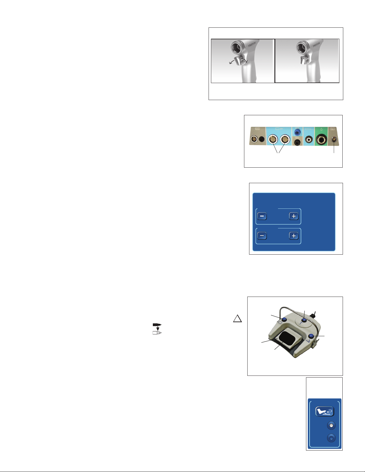
CONNECT TRITON ELECTRIC HIGHTORQUE HANDPIECE TO IPC
Locate the Triton Electric High-Torque Handpiece connection port on the connector panel (Figure
2-8) and insert the connector.
Note: To insert multi-pin connectors (indicated by a silver or red mark on the connector), align the
mark on the connector to the mark on the console, then insert the connector.
Figure 2-8. IPC Triton Connection Ports
1 Triton Connection 2 Footpedal Connection
TRITON ELECTRIC HIGHTORQUE HANDPIECE TOUCHSCREEN CONTROLS
To adjust Triton Electric High-Torque Handpiece variable speed, on the IPC touchscreen, in the FWD
Speed or REV Speed control box (Figure 2-9), press the plus button to increase variable speed or the
minus button to decrease variable speed.
RUN: Trigger control in the vertical
position will allow activation of the
handpiece.
(1) (2)
Figure 2-9. Triton Touchscreen
TRITON
TRITON
FWD Speed
FWD Speed
+
+
+
+
100
100
%
%
REV Speed
REV Speed
+
+
+
+
TRITON ELECTRIC HIGHTORQUE HANDPIECE MODE SELECT SWITCH
Use the mode select switch to change the handpiece from forward to reverse when the handpiece is the active handpiece. When the handpiece
is the inactive handpiece, use the mode select switch to activate the handpiece.
TRITON ELECTRIC HIGHTORQUE HANDPIECE MULTIFUNCTION FOOTPEDAL CONTROLS
Important: By default, press each button on the footpedal for at least 100 mS for the selection to
become active. Use the IPC touchscreen Settings screen to change the default value.
To use the multifunction footpedal (Figure 12-9) to control the handpiece do the following:
• To toggle between the start/stop mode and variable speed mode, press the control button.
• To change the handpiece, press the handpiece button.
Triton Electric High-Torque Handpiece Reverse Footpedal Control
When you connect the optional foot pedal to the IPC console, the pedal can be used as an
alternative method of activating Reverse mode (without manipulating the Mode select switch at
the bottom of the handpiece). When the pedal is connected, the Reverse Pedal control box appears
on the screen (Figure 2-11).
Note: By default, pedal functionality is turned OFF.
1. To use the pedal, press ON in the Reverse Pedal control box on the IPC touch screen.
2. With the pedal turned on, step on the foot pedal to put the handpiece into Reverse mode (regardless of what position
the Mode select switch is in).
NOTE: The trigger control must be pressed to activate the handpiece, even when you are stepping on the foot pedal.
3. Remove your foot from the pedal to return the handpiece to the mode currently dened by the Mode select switch on
the handpiece.
Figure 2-10. Multifunction Footpedal
1 Mode Button
2 Foot Pedal
3 Slip-resistant foot pad
4 Control Button
5 Handpiece Button
Figure 2-11.
Reverse Pedal
Control Box
Reverse Pedal
Reverse Pedal
ON
ON
OFF
OFF
REV
REV
2-3
Page 22

TRITON ELECTRIC HIGH-TORQUE HANDPIECE
TRITON ELECTRIC HIGHTORQUE HANDPIECE CLEANING AND STERILIZATION INSTRUCTIONS
Refer to document M000030A322 in the Cleaning and Sterilization section.
TRITON ELECTRIC HIGHTORQUE HANDPIECE TECHNICAL SPECIFICATIONS
Triton Electric High-Torque Handpiece ED500
Size 3.5 in L x 5.4 in H x 1.1 in W
Weight 2.1 lbs
Speed 400-18000 cpm (actual speed depends on attachment used)
Duty Cycle for Applied Part Cycle Time: 20 seconds on maximum / 20 seconds o minimum
Maximum number of cycles before resting handpiece: 6
Maximum number of cycles before resting attachment: 3
Minumum rest period: 25 minutes
2-4
Page 23
SUCTION IRRIGATOR
SUCTION IRRIGATOR
The following instructions for the Suction Irrigator are in addition to “Set up the IPC” general assembly instructions. Complete IPC setup, then
continue to the instructions below.
SUCTION IRRIGATOR ASSEMBLY
Figure 3-1. Suction Irrigator
1. Connect suction tubing from a suction source to the suction tting on the Suction
Irrigator (Figure 3-1).
2. On the IPC touchscreen (Figure 1-5), press the pumps button.
3. On the IPC pumps screen (Figure 1-6), select a pump for the Suction Irrigator.
Note: When using a handpiece that connects to a pump, the IPC automatically
incorporates the Suction Irrigator at the pump not in use by the handpiece.
4. Connect irrigation tubing from the IPC cartridge (Figure 1-8) to irrigation tting on
(3)
the Suction Irrigator (Figure 3-1).
5. On the irrigation tubing, turn the clamp to OPEN.
(4)
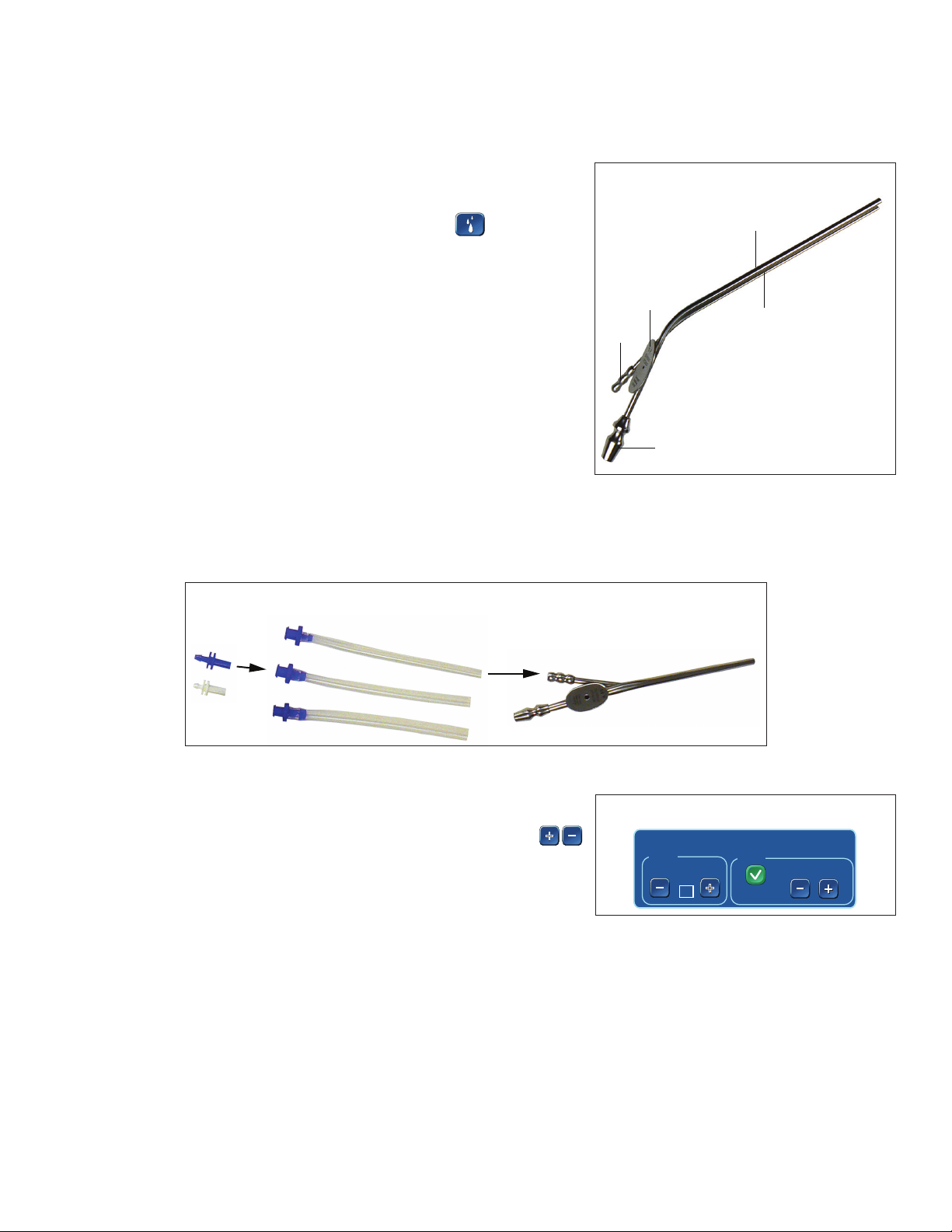
SUCTION IRRIGATOR ADAPTER KIT
1. Connect an adapter to the high-speed irrigation tubing (blue adapter) or the IPC tubing (white adapter).
2. Connect an adapter to the irrigation connector tube (Figure 3-2).
3. Connect an irrigation connector tube to the irrigation tting on the Suction Irrigator.
Figure 3-2. Suction Irrigator Adapter Kit
(1)
(2)
1 Suction Tube
2 Irrigation Tube
3 Tube Size
4 Irrigation Fitting
5 Suction Fitting
(5)
SUCTION IRRIGATOR TOUCHSCREEN CONTROLS
To set or adjust Suction Irrigator controls, on the IPC touchscreen, in the Suction Irrigator
control box (Figure 3-3), do the following:
+
• To set the tubing size, in the Size control box, press the plus and minus buttons.
Note: The system defaults to size 8.
• To enable or disable the irrigation ow, in the Flow control box, select the On/O box.
• To adjust the ow rate, in the Flow control box, press the plus and minus buttons.
+
Figure 3-3. Suction Irrigator Touchscreen
Suction Irrigator
Size
8
Fr
Flow
IIIIIIIII
+
+
On
+
+
3-1
Page 24

Page 25

ENDO-SCRUB 2
(5)
ENDO-SCRUB 2
The following instructions for the Endo-Scrub 2 are in addition to “Set up the IPC” general assembly instructions. Complete IPC setup, then
continue to the instructions below. Refer to the Endo-Scrub 2 System Instructions for Use, Endo-Scrub Sheaths Instructions for Use and EndoScrub 2 Finger Switch Instructions for Use for additional information.
The IPC System incorporates Endo-Scrub 2 functionality by using irrigation pump number one (1) and controlling operation with the touch
screen and an external footswitch or nger switch.
DO NOT use the Endo-Scrub 2 for infusion, for disinfection or sterilization of an endoscope, or for suction removal of blood and debris.
Use the Endo-Scrub 2 sheath only with an endoscope listed on the sheath product label, as malfunction or poor performance could result.
Figure 4-1. Endo-Scrub 2 Fingerswitch
(1)
(2)
1 Fingerswitch
2 Endo-Scrub 2 sheath
3 Irrigation Connection
(3)
(4)
4 Light Connection
5 Fingerswitch Cable
ENDOSCRUB 2 ASSEMBLY
1. Wet the endoscope.
2. Slowly, slide the approved endoscope into the Endo-Scrub 2 sheath (Figure 4-3).
3. Connect the irrigation tubing and a light source (Figure 4-4).
Figure 4-3. Endo-Scrub 2 Assembly
Figure 4-2. Endo-Scrub 2 Footpedal
Figure 4-4. Endo-Scrub 2 Assembly
ENDOSCRUB 2 FINGERSWITCH ASSEMBLY
If using the Endo-Scrub 2 ngerswitch, complete the following:
1. Slide the ngerswitch onto the Endo-Scrub 2 sheath (Figure 4-1). Align the cutout section of the ring with the luer connector of the
tubing set. The ngerswitch is properly installed when the cutout section of the ring is rmly seated against the luer connector.
2. Activate the pump by pressing the actuator button located on the ngerswitch.
ENDOSCRUB 2 ACTIVATION
Note: The procedure below also applies if using the multifunction footpedal.
1. To activate the Endo-Scrub wash cycle, press and release the ngerswitch.
2. To initiate a continuous ow of irrigant, press and hold the ngerswitch.
CONNECT ENDOSCRUB 2 TO IPC CONSOLE
1. Locate the Endo-Scrub 2 connector cover on the back of the IPC console (Figure 1-2).
2. Insert a small screwdriver in the notch on the cable connector cover and pull.
3. Connect the control switch cable to the cable connector.
4. Connect the Endo-Scrub 2 ngerswtich (Figure 4-1) or the footpedal (Figure 4-2) to the
console (Figure 4-5).
Figure 4-5. IPC Endo-Scrub 2 Connection Port
1 Fingerswitch or Footpedal Connection Port
(1)
4-1
Page 26

ENDO-SCRUB 2
ENDOSCRUB 2 TOUCHSCREEN CONTROLS
To set or adjust Endo-Scrub 2 controls, on the IPC touchscreen, in the Flow section of the Endo-Scrub 2 control box (Figure 4-6), do the following:
• To enable the Endo-Scrub 2 , press the On/O check-box.
• To adjust the ow rate, press the plus button to increase ow rate or the minus button to
decrease ow rate.
• To prime the pump, press the prime button.
+
+
Figure 4-6. Endo-Scrub 2 Touchscreen
EndoScrub 2
Flow
+
+
3
Setting
PrimeOn
ENDOSCRUB 2 CLEANING AND STERILIZATION INSTRUCTIONS
Refer to document 68E4005 in the Cleaning and Sterilization section.
Endo-Scrub 2 Foot Pedal Cleaning
Important: If debris is found under the foot pedal boot, return for warranty service.
DO NOT emerse or sterilize the foot pedal unit.
DO NOT use alcohol, other solvents or abrasive cleaners.
1. Wipe down the Endo-Scrub 2 foot pedal with a cloth dampened with a neutral enzymatic detergent, pH 6.0-8.0 or phenol based
disinfectant.
2. Dry the unit with a clean, non-abrasive cloth.
4-2
Page 27
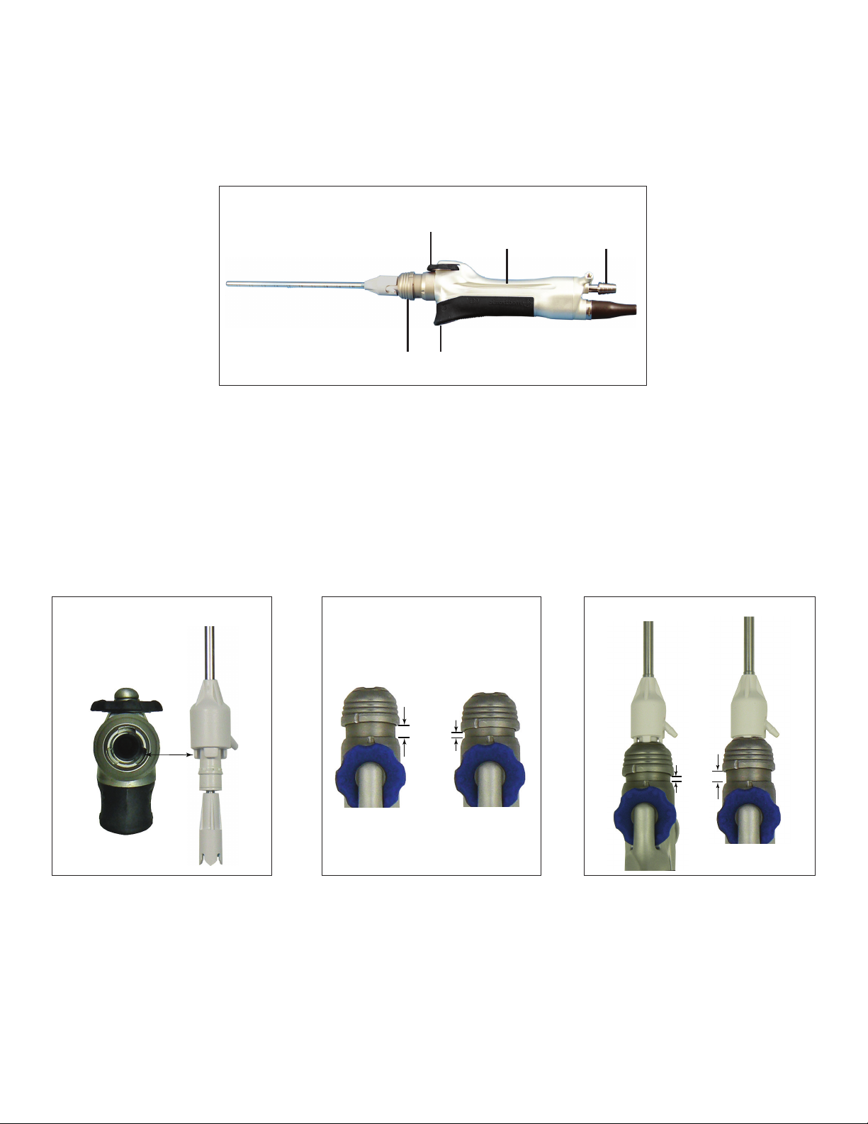
SPINE SHAVER (SC1) HANDPIECE
(1)
SPINE SHAVER (SC1) HANDPIECE
DEVICE DESCRIPTION
The following instructions for the Spine Shaver (SC1) Handpiece are in addition to “Set up the IPC” general assembly instructions. Complete IPC
setup, then continue to the instructions below. Refer to the Midas Rex User’s Guide for additional information.
The IPC incorporates the Midas Rex Spine Shaver (SC1) at pump 2. Control operation of the Midas Rex Spine Shaver (SC1) with the IPC
touchscreen and the multifunction footpedal.
Figure 5-1. Spine Shaver (SC1) Handpiece
(2) (3)
1 Finger Wheel
2 Irrigation Tubing Groove
3 Suction Barb
4 Locking Collar
5 Finger Wheel Lock
SPINE SHAVER (SC1) BLADE OR BUR ASSEMBLY
1. Insert the tool aligning the tabs with the notches (Figure 5-2). Orientate the irrigation barb to the left or right side.
Note: The StraightShot M4 uses a four-tab alignment system.
• For rotating straight blades, orient the irrigation barb at the 3 o’clock position for right-handed surgeons and 9 o’clock for left-handed
surgeons.
• For rotating curved blades, orient the irrigation barb at 3 o’clock.
2. Press the locking collar (Figure 5-3).
3. Release the locking collar.
Note: If collar does not return to full out position adjust the nger wheel with small back-and-forth motions until collar pops out.
4. Pull on the blade or bur to ensure engagement and visually check to make sure the distal tip of the inner blade is in contact with the
distal tip of the outer cannula (Figure 5-4).
(4) (5)
Figure 5-2. Spine Shaver (SC1) Assembly
Figure 5-3. Spine Shaver (SC1) Assembly
Figure 5-4. Spine Shaver (SC1) Assembly
5-1
Page 28

SPINE SHAVER (SC1) HANDPIECE
(1) (2)
SPINE SHAVER (SC1) SUCTION AND IRRIGATION TUBE ASSEMBLY
1. Attach a suction tube to the suction source (Figure 5-5) and an irrigation tube on the irrigation barb (Figure 5-5).
2. Secure suction and irrigation in the irrigation groove on the handpiece (Figure 5-6).
Figure 5-5. Spine Shaver (SC1) Suction and Irrigation Assembly
Figure 5-6. Spine Shaver (SC1) Suction and Irrigation Assembly
CONNECT SPINE SHAVER (SC1) TO IPC CONSOLE
Locate the Spine Shaver (SC1) connection port on the connector panel (Figure
5-7) and insert the connector.
Note: To insert multi-pin connectors (indicated by a silver or red mark on the
connector), align the mark on the connector to the mark on the console, then
insert the connector.
Figure 5-7. Spine Shaver (SC1) IPC Connection Ports
1 Spine Shaver (SC1) Handpiece Connection Port
2 Multifunction Footpedal Connection Port
MICRODEBRIDER BLADE CONTROL
Important: If airway blade becomes clogged during use, 1-5cc of irrigant could be aspirated by
the patient before you detect the clog.
Note: Periodically submerse blade tip in sterile water, with suction on, to keep blades clear
during the procedure.
• To rotate the outer blade (Figure 5-8), use the nger wheel (Figure 5-1).
• To rotate the inner blade, use the Blade Position control box on the IPC touchscreen. Refer to
the related accessory Controls topic for further information.
Figure 5-8. Blade Dissection
(4)
(1) (2) (3)
1 Outer Blade
2 Inner Blade
3 Outer Sleeve
4 Suction Flow in through inner blade
Irrigation Flow between inner and outer blades
5-2
Page 29

SPINE SHAVER (SC1) HANDPIECE
(5)
SPINE SHAVER (SC1) TOUCHSCREEN CONTROLS
To set or adjust Spine Shaver (SC1) controls, on the IPC touchscreen, in the control box (Figure 5-9), do the following:
• To change rotation mode, in the Mode control box select OSC (oscillating) or FWD (forward).
• To adjust speed, in the Speed control box, press the plus button to increase speed and the
minus button to decrease.
+
+
Forward Mode: Default, 12000 rpm; variable adjustment from 50 to 12000 rpm.
Oscillate Mode: Default, 3400 cpm; variable adjustment from 50 to 5000 rpm.
• To adjust ow rate for blade irrigation, in the Irrigation control box, press the plus and minus
buttons.
Forward Mode: Default, 30cc per minute.
Oscillate Mode: Default, 60cc per minute.
Note: To adjust ow rate, you can use the touchscreen or the IntelliFlow Irrigation remote
control.
Figure 5-9. Spine Shaver (SC1) Touchscreen
SC1 Handpiece
Speed
3400
Blade Position
Irrigation
60
cc/min
Flow
+
+
CPM
180°
+
+
Prime
Mode
OSC
FWD
• In oscillating mode only, you can use the Blade Position control box to do any of the
following:
To rotate the inner blade 180 press the delta button.
180º
To rotate the inner blade in small increments, press the clockwise or counter-clockwise buttons.
Note: The motion indicator indicates rotation direction of the blade.
• To rotate the outer blade, use the nger wheel (Figure 5-1).
SPINE SHAVER (SC1) MULTIFUNCTION FOOTPEDAL CONTROLS
Important: By default, press each button on the footpedal for at least 100 mS for the selection to become active. Use the IPC touch screen
Settings screen to change the default value.
To use the multifunction footpedal (Figure 5-10) to control the handpiece do the following:
• To select forward or oscillating mode, press the mode button.
• To start or adjust the speed of a handpiece in variable mode, press the foot pedal.
• To rotate the inner blade (180) press the control button.
• To change the handpiece, press the handpiece button.
SPINE SHAVER (SC1) CLEANING AND STERILIZATION INSTRUCTIONS
Refer to document 68E3282 in the Cleaning and Sterilization section.
SPINE SHAVER (SC1) TECHNICAL SPECIFICATIONS
Spine Shaver (SC1) ED100
Size 14.3 cm legnth x 1.8 cm width (1898200T)
Weight 228g 1898200T
240g 1897200, 1897201
254g 1897200T
Speed 50-5000 rpm oscillate
50-12000 rpm forward
Duty Cycle for Applied Part Maximum on time = 60 seconds. Minimum o time = 30 seconds.
Figure 5-10. Multifunction Footpedal
(1)
(2)
(3)
1 Mode Button
2 Foot Pedal
3 Slip-resistant foot pad
4 Control Button
5 Handpiece Button
(4)
5-3
Page 30

Page 31

STRAIGHTSHOT M4, STRAIGHTSHOT MAGNUM II and STRAIGHTSHOT III
(1)
(2)
STRAIGHTSHOT M4, STRAIGHTSHOT MAGNUM II AND STRAIGHTSHOT III
DEVICE DESCRIPTION
Note: The StraightShot III is not for sale in the United States.
The following instructions for the StraightShot M4, the StraightShot Magnum II and the StraightShot III are in addition to “Set up the IPC”
general assembly instructions. Complete IPC setup, then continue to the instructions below.
The IPC incorporates the microdebrider at pump 2. Control operation of the microdebrider with the IPC touchscreen and the multifunction
footpedal.
When the IPC detects both the StraightShot M4 and the Legend EHS Stylus handpieces, the system defaults Pump 2 to the Shared
conguration. You must manually move the irrigation tubing from the inactive to the active handpiece. Use the pumps screen to override the
Shared default by selecting the StraightShot M4 or the Legend EHS Stylus for Pump 1. Refer to “Set up and Prime Pumps” for more information.
Note: The Endo-Scrub 2 is available to all microdebriders. The system automatically turns on the Endo-Scrub 2 only when it also detects the
StraightShot M4. You must manually set the Endo-Scrub 2 for all other microdebriders. Refer to “Set up and Primp Pumps” for details.
Figure 6-1. StraightShot M4 Handpiece
1 Finger Wheel
2 Irrigation Tubing Groove
3 Suction Barb
4 Locking Collar
5 Finger Wheel Lock
(4) (5)
(2) (3)
Figure 6-2. StraightShot Magnum II and III Handpiece
(1)
1 Suction Barb
2 Locking Collar
STRAIGHTSHOT M4 BLADE OR BUR ASSEMBLY
1. Insert the tool aligning the tabs with the notches (Figure 6-3). Orientate the irrigation barb to the left or right side.
Note: The StraightShot M4 uses a four-tab alignment system.
• For rotating straight blades, orient the irrigation barb at the 3 o’clock position for right-handed surgeons and 9 o’clock for left-handed
surgeons.
• For rotating curved blades, orient the irrigation barb at 3 o’clock.
• For the M4 rotating blade, adjust the nger wheel with small back-and-forth motions.
2. Press the locking collar (Figure 6-4).
3. Release the locking collar.
Note: If the collar does not return to full out position adjust the nger wheel with small back-and-forth motions until collar pops out.
4. Pull on the blade or the bur to ensure engagement and visually check to make sure the distal tip of the inner blade is in contact with the
distal tip of the outer cannula (Figure 6-5).
Figure 6-3. M4 Blade or Bur Assembly
Figure 6-4. M4 Blade or Bur Assembly
Figure 6-5. M4 Blade or Bur Assembly
6-1
Page 32

STRAIGHTSHOT M4, STRAIGHTSHOT MAGNUM II and STRAIGHTSHOT III
STRAIGHTSHOT M4 SUCTION AND IRRIGATION TUBE ASSEMBLY
1. Attach a suction tube to the suction source and an irrigation tube on the irrigation barb (Figure 6-6).
2. Secure suction and irrigation in the irrigation groove on the handpiece (Figure 6-7).
Figure 6-6. M4 Suction and Irrigation Assembly
Figure 6-7. M4 Suction and Irrigation Assembly
STRAIGHTSHOT MAGNUM II AND STRAIGHTSHOT III BLADE AND BUR ASSEMBLY
1. Press the collet and insert blade in collet (Figure 6-8).
2. Release the collet (Figure 6-8).
3. Pull on the tool to ensure engagement and check distal tip of inner blade is in contact with the distal tip of the outer cannula.
Figure 6-8. StraightShot II and III Blade and Bur Assembly
STRAIGHTSHOT MAGNUM II AND STRAIGHTSHOT III SUCTION AND IRRIGATION ASSEMBLY
1. Attach a suction tube to the suction source and an irrigation tube on the irrigation barb (Figure 6-9).
2. Secure suction and irrigation tubing with tubing clips.
Figure 6-9. StraightShot II and III Suction and Irrigation Assembly
6-2
Page 33

STRAIGHTSHOT M4, STRAIGHTSHOT MAGNUM II and STRAIGHTSHOT III
(4)
CONNECT STRAIGHTSHOT TO IPC CONSOLE
Locate the StraightShot connection port on the connector panel (Figure 6-10) and
insert the connector.
Note: To insert multi-pin connectors (indicated by a silver or red mark on the
connector), align the mark on the connector to the mark on the console, then
insert the connector.
Figure 6-10. M4 and Magnum II and III IPC Connection Ports
1 M4 and Magnum II and III Handpiece Connection Port
2 Multifunction Footpedal Connection Port
(1) (2)
MICRODEBRIDER BLADE CONTROL
Important: If airway blade becomes clogged during use, 1-5cc of irrigant could be aspirated by
the patient before you detect the clog.
Note: Periodically submerse blade tip in sterile water, with suction on, to keep blades clear
during the procedure.
• To rotate the outer blade (Figure 5-8), use the nger wheel (Figure 6-11).
• To rotate the inner blade, use the Blade Position control box on the IPC touchscreen. Refer to
the related accessory Controls topic for further information.
Figure 6-11 Blade Dissection
(1) (2) (3)
1 Outer Blade
2 Inner Blade
3 Outer Sleeve
4 Suction Flow in through inner blade
Irrigation Flow between inner and outer blades
STRAIGHTSHOT M4, STRAIGHTSHOT MAGNUM II AND STRAIGHTSHOT III TOUCHSCREEN CONTROLS
Note: The StraightShot M4, StraightShot Magnum II and StraightShot III handpiece screens feature the same controls as those shown on the
StraightShot M4 Control Box.
Note: When you stop the blade, one of the following occurs:
• If the IPC button is visible on the touchscreen, the inner blade returns to the same position it
began.
• If the XPS button is visible on the touchscreen, the inner blade stops the current position.
To set or adjust StraightShot controls, on the IPC touchscreen, in the StraightShot Handpiece
control box (Figure 6-12), do the following:
• To change rotation mode, select OSC (oscillating) or FWD (forward).
Note: The system displays the default oscillating or forward mode speed.
+
• To adjust speed, in the Speed control box, press the plus button or minus buttons.
+
Forward Mode: Default, 12000 rpm; variable adjustment from 50 to 12000 rpm.
Oscillate Mode: Default, 5000 rpm; variable adjustment from 50 to 5000 rpm.
• To adjust ow rate for blade irrigation, in the Irrigation control box, press the plus or minus buttons.
Forward Mode: Default, 30cc per minute.
Oscillate Mode: Default, 60cc per minute.
Note: To adjust ow rate, you can use the touchscreen or the IntelliFlow Irrigation remote control.
Figure 6-12. StraightShot IPC Touchscreen
• To rotate outer blade, use the nger wheel (Figure 6-1).
• In oscillating mode only, you can use the Blade Position control box to do any of the following:
Note: The motion indicator indicates rotation direction of the blade.
To enable the multifunction footpedal to change rotation displacement, press the delta button.
To rotate inner blade in small increments, press the counter-clockwise buttons.
60º 180º
6-3
Page 34

STRAIGHTSHOT M4, STRAIGHTSHOT MAGNUM II and STRAIGHTSHOT III
(5)
STRAIGHTSHOT M4, STRAIGHTSHOT MAGNUM II AND STRAIGHTSHOT III MULTIFUNCTION FOOTPEDAL
CONTROLS
Important: By default, press each button on the footpedal for at least 100 mS for the selection to become active. Use the IPC touch screen
Settings screen to change the default value.
To use the multifunction footpedal (Figure 6-13) to control the handpiece do the following:
Figure 6-13. Multifunction Footpedal
• To select forward or oscillate mode, press the mode button.
(1)
• To start or adjust the speed of a handpiece in variable mode, press the foot pedal.
• To rotate the inner blade (60 or 180), press the control button.
• To change the handpiece, press the handpiece button.
(2)
(3)
1 Mode Button
2 Foot Pedal
3 Slip-resistant foot pad
4 Control Button
5 Handpiece Button
(4)
STRAIGHTSHOT M4, STRAIGHTSHOT MAGNUM II AND STRAIGHTSHOT III CLEANING AND
STERILIZATION INSTRUCTIONS
Refer to document 68E3282 in the Cleaning and Sterilization section.
STRAIGHTSHOT M4 TECHNICAL SPECIFICATIONS
StraightShot M4 1898200T
Size 14.3 cm legnth x 1.8 cm width (1898200T)
Weight 228g 1898200T
240g 1897200, 1897201
254g 1897200T
Speed 50-5000 rpm oscillate
50-12000 rpm forward
Duty Cycle for Applied Part The StraightShot M4 handpiece under full load is rated for intermittent operation per the following:
Maximum On Time: 60 seconds
Minimum O Time: 30 seconds
STRAIGHTSHOT MAGNUM II AND STRAIGHTSHOT III TECHNICAL SPECIFICATIONS
StraightShot Magnum II 1897200
StraightShot III 1897201
Size 17 cm legnth x 1.6 cm width (1897200/1897201)
Weight 240g 1897200, 1897201
Speed 50-5000 rpm oscillate
50-12000 rpm forward
Duty Cycle for Applied Part Under full load is rated for intermittent operation per the following:
Maximum On Time: 60 seconds
Minimum O Time: 30 seconds
6-4
Page 35

LEGEND EHS and LEGEND EHS STYLUS
LEGEND EHS AND LEGEND EHS STYLUS
The Legend EHS motor (Figure 7-1) is a high speed, high torque, reversible electric motor used to dissect bone and biomaterial at selectable
speeds from 200 to 75000 rpm.
The Legend EHS Stylus motor (Figure 7-2) is a smaller, compact, high speed, high torque, reversible electric motor used to dissect bone and
biomaterials at selectable speeds from 200 to 75000 rpm.
The following instructions for the Legend EHS and Legend EHS Stylus are in addition to “Set up the IPC” general assembly instructions.
Complete IPC setup, then continue to the instructions below.
Figure 7-1. Legend EHS Motor
(3)
(1) (2)
1 Rotating Collet
2 Stationary Collet
3 4-pin Cable Connection
Figure 7-2. Legend EHS Stylus Motor
(1)(2)
(3)
(4)
(5)
1 Stationary Collet
2 Rotating Collet
3 Ground Connector
4 4-pin Cable Connection
5 Locking Sleeve
LEGEND EHS AND LEGEND EHS STYLUS ATTACHMENT ASSEMBLY
Refer to “Legend EHS, Legend EHS Stylus and Stylus Touch Attachments” for attachment assembly instructions.
CONNECT LEGEND EHS CABLE TO MOTOR
Note: The Legend EHS Stylus motor cable is integrated in the handpiece and cannot be removed from the motor.
To connect the Legend EHS cable to the Legend EHS motor, align the mark on the cable to the red mark on the motor (Figure 7-3) and connect
the two pieces.
Figure 7-3. Legend EHS Motor Cable Connection
REMOVE LEGEND EHS CABLE FROM MOTOR
Note: The Legend EHS Stylus motor cable is integrated in the handpiece and cannot be removed from the motor.
To remove the Legend EHS cable from the Legend EHS motor, (1) push the cable towards the motor, then (2) pull out the cable by the locking
ring ONLY (Figure 7-4).
Figure 7-4. Disconnect Legend EHS Cable from Motor
(1)(2)
7-1
Page 36

LEGEND EHS and LEGEND EHS STYLUS
(5)
Mode
Mode
CONNECT LEGEND EHS OR LEGEND EHS STYLUS TO IPC
Locate the Legend EHS or Legend EHS Stylus connection port on the connector panel (Figure 7-5) and insert the connector.
Note: To insert multi-pin connectors (indicated by a silver or red mark on the connector), align the mark on the connector to the mark on the
console, then insert the connector.
The IPC incorporates the Legend EHS or Legend EHS Stylus irrigation at pump 1. When
Figure 7-5. Legend EHS and Legend EHS Stylus
Connection Ports
the system detects the Legend EHS or Legend EHS Stylus, pump 2 defaults to None.
When the IPC detects both the Legend EHS Stylus handpieces and the StraightShot M4,
the system defaults Pump 2 to the Shared conguration. You must manually move the
irrigation tubing from the inactive to the active handpiece. Use the pumps screen to
override the Shared default by selecting the StraightShot M4 or the Legend EHS Stylus
for Pump 1. Refer to “Set up and Prime Pumps” for more information.
Control operation of the Legend EHS or Legend EHS Stylus with the IPC touchscreen and
the multifunction footpedal.
(1) (2) (3)
1 Legend EHS Motor Connection Port
2 Legend EHS Stylus Motor Connection Port
3 Multifunction Footpedal Connectoin Port
LEGEND EHS AND LEGEND EHS STYLUS TOUCHSCREEN CONTROLS
To set or adjust Legend EHS or Legend EHS Stylus controls, on the IPC touchscreen, in the control box (Figure 7-6), do the following:
• To change rotation mode, in the Mode control box, select FWD (forward) or REV
(reverse).
Important: System conguration may be dierent from the default. If the REV (reverse)
button appears raised (Figure 7-7) and does not have a selectable radio button, you
cannot select the reverse mode. If the REV button appears concave (Figure 7-7) and has
a selectable radio button, you can select the reverse mode via the touchscreen or the
multifunction footpedal.
• To adjust speed in forward (FWD) or reverse (REV) mode, in the Speed control box, press
+
the plus button to increase speed or the minus button to decrease speed.
+
Default, 70000 rpm; variable adjustment from 200 to 75000 rpm.
• To adjust ow rate for optional irrigation, in the Irrigation control box, press the plus
button to increase ow or the minus button to decrease ow.
Default, 0cc per minute in forward or reverse mode.
Note: To adjust ow rate, you can use the touchscreen or the IntelliFlow Irrigation
remote control.
• Legend EHS Stylus ONLY: To adjust the rate of the motor’s acceleration and deceleration,
in the Acceleration control box, press the plus button to increase acceleration or the minus
button to decrease acceleration.
Figure 7-6. Legend EHS Stylus Touchscreen
Speed
Stylus
+
60000
Acceleration
100
+
+
%
Irrigation
+
+
0
cc/min
Flow
Figure 7-7. Legend EHS or Legend EHS Stylus Mode
FWD
+
RPM
Prime
Mode
FWD
REV
FWD
LEGEND EHS AND LEGEND EHS STYLUS MULTIFUNCTION FOOTPEDAL CONTROLS
Important: By default, press each button on the footpedal for at least 100 mS for the selection
to become active. Use the IPC touch screen Settings screen to change the default value.
To use the multifunction footpedal (Figure 7-8) to control the handpiece do the following:
• To select forward or reverse mode, press the mode button.
• To start or adjust the speed of a handpiece in variable mode, press the foot pedal.
• To toggle between the start/stop mode and variable speed mode, press the control
button.
• To change the handpiece, press the handpiece button.
Figure 7-8. Multifunction Footpedal
1 Mode Button
2 Foot Pedal
3 Slip-resistant foot pad
REV
REV
(1)
(4)
(2)
(3)
4 Control Button
5 Handpiece Button
7-2
Page 37

LEGEND EHS and LEGEND EHS STYLUS
LEGEND EHS AND LEGEND EHS STYLUS CLEANING AND STERILIZATION INSTRUCTIONS
Refer to documents M000030A234 and M000030A235 in the Cleaning and Sterilization section.
LEGEND EHS TECHNICAL SPECIFICATIONS
Legend EHS EM100-A
Size 9.02 cm length x 2.03 cm diameter
Weight 180g
Speed 75000 rpm forward/reverse
Duty Cycle for Applied Part For use in operating room temperatures up to 400C (1040F), the Legend EHS Motor is rated for a cutting time
of 3 minutes at 70000 rpm.
For normal operating room temperatures (typically 200C/680F), the Legend EHS Motor is rated for cutting
time of 10 minutes followed by 25 minutes or rest.
The Legend EHS Motor is rated for intermittent use of 20 seconds ON / 20 seconds OFF, indenitely at 70000
rpm.
LEGEND EHS STYLUS TECHNICAL SPECIFICATIONS
Legend EHS EM200
Size 7.77 cm length x 1.65 cm diameter
Weight 90g
Speed 75000 rpm forward/reverse
Duty Cycle for Applied Part For use in operating room temperatures up to 400C (1040F), the Legend EHS Stylus Motor is rated for 3
minutes at 60000 rpm followed by 25 minutes or rest.
For normal operating room temperatures (typically 200C/680F), the Legend EHS Stylus Motor is rated for
cutting indenintely at 60000 rpm.
7-3
Page 38

Page 39

STYLUS TOUCH
(1) (2)
STYLUS TOUCH
The Stylus Touch (Figure 8-1) is a small, compact, high-speed, high-torque, reversible electric motor used to dissect bone and biomaterials at
variable speeds from 200 to 75000 rpm. The Stylus Touch motor includes a rotating nger lever that emulates the functions of the multifunction
footpedal.
The following instructions for the Stylus Touch are in addition to “Set up the IPC” general assembly instructions. Complete IPC setup, then
continue to the instructions below.
Figure 8-1. Stylus Touch Motor
(1)
(5) (6)
1 Telescoping Finger Rest
2 Finger Lever
3 Finger Lever Safe Mode Switch
(2)
(3)
4 Control Lever Ring
5 Stationary Collet
6 Rotating Collet
(4)
STYLUS TOUCH ATTACHMENT ASSEMBLY
Refer to “Legend EHS, Legend EHS Stylus and Stylus Touch Attachments” for attachment assembly instructions.
ROTATE STYLUS TOUCH FINGER LEVER
1. Press the control lever ring forward (Figure 8-2).
2. Rotate the lever clockwise or counter clockwise until the lever locks in a new position.
Figure 8-2. Stylus Touch Finger Lever Rotation
(1)
(2)
CONNECT STYLUS TOUCH TO IPC CONSOLE
Locate the Stylus Touch connection port on the connector panel (Figure 8-3) and insert the connector.
Note: To insert multi-pin connectors (indicated by a silver or red mark on the connector), align the mark on the connector to the mark on the
console, then insert the connector.
The IPC incorporates the Stylus Touch at pump 1. If you do not use irrigation for
the Stylus Touch, manually change the Pump 1 to None. Refer to “Set up and
Prime Pumps” for more information.
Control operation of the Stylus Touch with the IPC touchscreen and the
multifunction footpedal.
Figure 8-3. Stylus Touch Connection Ports
1 Stylus Touch Connection Port
2 Multifunction Footpedal Connection Port
8-1
Page 40

STYLUS TOUCH
Speed
(5)
STYLUS TOUCH TOUCHSCREEN CONTROLS
To set or adjust Stylus Touch controls, on the IPC touchscreen, in the control box (Figure 8-4), do the following:
• To change rotation mode, in the Mode control box, select FWD (forward) or REV (reverse).
Important: To set the Stylus Touch to Safe Mode, on the Stylus Touch handpiece, switch
the Safe Mode nger lever (Figure 8-1) to on.
• To adjust speed, in the Speed control box, press the plus button to increase speed or the
minus button to decrease speed.
+
+
Default, 60000 rpm; variable adjustment from 200 to 75000 rpm.
Important: The handpiece does not operate in Safe Mode. If the Stylus Touch is in Safe
Mode, SAFE appears in the the Speed control box (Figure 8-5).
• To adjust rate of the motors acceleration and deceleration, in the Acceleration control
box, press the plus button to increase acceleration or the minus button to decrease
acceleration.
• To adjust ow rate for optional irrigation, in the Irrigation control box, press the plus
button to increase ow or the minus button to decrease ow.
Default, 0cc per minute.
Note: To adjust ow rate, you can use the touchscreen or the IntelliFlow Irrigation remote
control.
STYLUS TOUCH SAFETY SWITCH
Use the Stylus Touch safety switch to activate or deactivate the safe mode when the Stylus
Touch is the active handpiece. When the handpiece is the inactive handpiece, use the safety
switch to activate the handpiece.
Figure 8-4. Stylus Touch Touchscreen
Speed
60000
Acceleration
100
%
Irrigation
0
cc/min
Flow
Figure 8-5. Stylus Touch Safe Mode
SAFE
Stylus Touch
+
+
RPM
+
+
+
+
Prime
+
+
RPM
Control
Finger
Mode
FWD
REV
Foot
Both
STYLUS TOUCH MULTIFUNCTION FOOTPEDAL CONTROLS
Important: By default, press each button on the footpedal for at least 100 mS for the selection
to become active. Use the IPC touch screen Settings screen to change the default value.
To use the multifunction footpedal (Figure 8-6) to control the handpiece do the following:
• To select forward or reverse mode, press the mode button.
• To start or adjust the speed of a handpiece in variable mode, press the foot pedal.
• To toggle between the start/stop mode and variable speed mode, press the control
button.
• To change the handpiece, press the handpiece button.
Figure 8-6. Multifunction Footpedal
(1)
(2)
(3)
1 Mode Button
2 Foot Pedal
3 Slip-resistant foot pad
4 Control Button
5 Handpiece Button
STYLUS TOUCH CLEANING AND STERILIZATION INSTRUCTIONS
Refer to documents 68E4132 and M000030A235 in the Cleaning and Sterilization section.
STYLUS TOUCH TECHNICAL SPECIFICATIONS
Stylus Touch EM210
Size 15.26 cm length x 1.65 cm diameter
Weight 130g
Speed 75000 rpm forward/reverse
Duty Cycle for Applied Part For use in operating room temperatures up to 400C, the Legend EHS Stylus Touch Motor is rated for 3
minutes at 60000 rpm followed by 25 minutes or rest.
For normal operating room temperatures (typically 200C), the Legend EHS Stylus Touch Motor is rated for
cutting indenitely at 60000 rpm.
(4)
8-2
Page 41

LEGEND EHS, LEGEND EHS STYLUS, and STYLUS TOUCH ATTACHMENTS
LEGEND EHS, LEGEND EHS STYLUS AND STYLUS TOUCH ATTACHMENTS
The following instructions for the Legend EHS, Legend EHS Stylus and Stylus Touch attachments are in addition to “Set up the IPC” and motorspecic general instructions. Complete IPC setup, motor specic instructions and then continue to the instructions below.
DISSECTING TOOLS NOMENCLATURE
Note: Match the nomenclature and color code on the dissecting tool packaging to the same nomenclature and color code on the attachment.
Part numbers for dissecting tools follow a standard naming convention (Figure 9-1). A basic part number consists of ve characters,
representing the associated attachment length, the tool-head shape, and the tool-head diameter. Part numbers can also include a variety of
prexes to identify specic attachment types, as well as a variety of suxes to provide additional information about the dissecting tool. Tools
that use a design taken from the Mednext line are designated by an additional “-MN” sux.
Figure 9-1. Dissecting Tool Nomenclature Naming Convention
9 M H 3 0
(1) (2) (3) (4) (5) (6)
1 Optional Prex
2 Attachment Length
3 Tool Head Shape
4 Tool Head Diameter (x.x millimeters)
5 Optional Sux
6 Optional “-MN” Sux
Tool Number Prexes
F For use with footed attachments.
MC For use with metal-cutting attachments.
T For use with telescoping attachments.
Tool Number Suxes
Tool Head Shapes
AC Acorn MH Match Head L Long S Spiral
BA Ball OV Oval D Diamond SH Short
CY Cylinder RT Reverse Taper X Extra
HM Hole Maker TA Tapered F Fine DC Diamond Coarse
HS Hole Saw TD Twist Drill C Carbide DX Diamond Extra Coarse
Note: More than one sux can be combined in a single part number.
ALIGN MOTOR COLLET
Note: An attachment will not seat on the Legend EHS, Legend EHS Stylus or Stylus Touch motor if the arrows on the collet ats are not aligned.
1. Verify alignment of arrows on motor collet ats. Prior to installation of an
attachment and dissecting tool on the Legend EHS, Legend EHS Stylus or Stylus
Touch motor, ensure that arrows on the motor collet ats are in proper alignment.
(Figure 9-2).
Figure 9-2. Correct Alignment
2. If the arrows are not aligned (Figure 9-3), use the motor wrench (Figure 9-4) to
turn the rotational collet until its arrow is aligned with the arrow on the stationary
collet.
Note: DO NOT use any other components except for the motor wrench to align
arrows on motor collet.
Figure 9-3. Incorrect Alignment
Figure 9-4. Motor Wrench
9-1
Page 42

LEGEND EHS, LEGEND EHS STYLUS, and STYLUS TOUCH ATTACHMENTS
STRAIGHT ATTACHMENT ASSEMBLY
Warnings: Refer to warnings W36 and W54.
Caution: Match the nomenclature and color code on the tool packaging to the same nomenclature and color code on the attachment.
Notes:
• An attachment will not seat on the motor if the arrows on the collet ats are not in alignment.
• The Legend EHS motors will not run properly unless the attachment is in the locked position.
• Smoke may be generated if attachment is not in the locked position.
1. Slide a straight attachment over the motor collet aligning triangular arrows on the attachment and the motor case (Figure 9-5). An
audible click, heard and perceptible by touch, conrms that the tool is fully seated.
Figure 9-5. Straight Attachment Assembly
2. Insert the tool into the attachment with a slight rotational motion (Figure 9-6). An audible click, heard and perceptible by touch, conrms
that the tool is fully seated.
Figure 9-6. Straight Attachment Assembly
3. Rotate the attachment in the direction indicated by arrow until the attachment alignment mark is directly in line with the locked symbol
(Figure 9-7).You will hear two clicks as the attachment is rotated.
Figure 9-7. Straight Attachment Assembly
4. Gently pull on the tool to ensure that it is locked into the handpiece.
Note: Tool should rotate freely, if not, unlock the attachment, re-seat the tool, and re-lock the attachment.
STRAIGHT ATTACHMENT DISASSEMBLY
1. Hold the motor in palm of hand. Rotate the attachment to the unlocked position.
2. Remove the dissecting tool from the attachment and discard the tool.
3. Use thumb and index nger to lift the attachment o of the motor.
ANGLED ATTACHMENT ASSEMBLY
Caution: When using an angled attachment, hold the handpiece assembly by the attachment so that the attachment does not inadvertently
loosen from the handpiece.
Notes:
• A dissecting tool may be installed and locked in the attachment before the angled attachment is installed onto the motor.
• Angled and straight attachments with the same length, marking and color band share the same dissecting tools.
• The Legend EHS Motors will not run properly unless the attachment is in the locked position.
• Smoke may be generated if attachment is not in the locked position.
1. With the tool lock in the unlocked position, insert a tool into the angled attachment with a slight rotational motion (Figure 9-8). An
audible click, heard and perceptible by touch, conrms that the tool is fully seated.
9-2
Figure 9-8. Angled Attachment Assembly
Page 43

LEGEND EHS, LEGEND EHS STYLUS, and STYLUS TOUCH ATTACHMENTS
2. Rotate the tool lock in the direction indicated by arrow until the tool lock alignment mark is directly in line with the locked symbol (Figure
9-9).
Figure 9-9. Angled Attachment Assembly
3. Gently pull on the tool to ensure that it is locked into the handpiece.
Note: Tool should rotates freely, if not, unlock the attachment, re-seat the tool, and re-lock the attachment.
4. Slide the angled attachment over the motor collet aligning triangular arrows on the attachment and the motor case. An audible click,
heard and perceptible by touch, conrms that the tool is fully seated.
5. Rotate the attachment in the direction indicated by the arrow until attachment alignment mark is directly in line with the locked symbol.
You will hear two clicks as the attachment is rotated.
6. Verify that both the attachment to motor alignment mark and the tool lock alignment mark are directly in line with the locked symbol
(Figure 9-10).
Figure 9-10. Angled Attachment Assembly
ANGLED ATTACHMENT DISASSEMBLY
1. Rotate the Tool Lock to the unlocked position to remove the tool from the attachment.
2. Rotate the attachment to the unlocked position and lift attachment o of the motor.
FIXED FOOTED ATTACHMENT ASSEMBLY
Warning: Refer to Warning W37.
1. Insert a dissecting tool into the motor collet with a slight rotational motion (Figure 9-11). An audible click, heard and perceptible by
touch, conrms that the tool is fully seated.
Figure 9-11. Footed Attachment Assembly
2. Slide the footed attachment over the dissecting tool onto the motor aligning triangular arrows on the attachment and the motor case
(Figure 9-12).
Figure 9-12. Footed Attachment Assembly
9-3
Page 44

LEGEND EHS, LEGEND EHS STYLUS, and STYLUS TOUCH ATTACHMENTS
3. Pull the footed attachment towards the motor and rotate the attachment to the locked position on the motor case (Figure 9-13).
Figure 9-13. Footed Attachment Assembly
FIXED FOOTED ATTACHMENT DISASSEMBLY
1. To remove the footed attachment, hold the motor in the palm of your hand. Push the sleeve on the footed attachment distally while
rotating the attachment to the unlocked position on the motor case. Release the sleeve (Figure 9-14).
Figure 9-14. Footed Attachment Disassembly
2. To avoid injury from the dissecting tool, use thumb and index nger to cautiously and slowly lift the attachment o of the motor and
away from the dissecting tool (Figure 9-15).
Figure 9-15. Footed Attachment Disassembly
3. Pull the dissecting tool out of the motor collet and discard the tool (Figure 9-16).
Figure 9-16. Footed Attachment Disassembly
ROTATING FOOTED ATTACHMENT ASSEMBLY
Warnings: Refer to Warnings, W20 and W52.
Notes:
• Rotating and xed footed attachments with the same length, marking and color band share the same dissecting tools.
• The footed end of the attachment has 360˚ of unrestricted rotation.
Attach the Rotating Footed attachment using the Fixed Footed Attachment Assembly Instructions.
ROTATING FOOTED ATTACHMENT DISASSEMBLY
Remove the Rotating Footed attachment using the Fixed Footed Attachment Disassembly Instructions.
CONTRAANGLE ATTACHMENT 16MF ASSEMBLY
1. On the IPC Touchscreen, adjust the speed setting to 62,000 rpm using the speed control buttons.
2. Slide the Contra-Angle Attachment over the motor collet aligning triangular arrows on the attachment and the motor case. An audible
click, heard and perceptible by touch, conrms that the tool is fully seated.
3. Rotate the attachment to the locked position on the motor case (Figure 9-17).
Figure 9-17. Contra-Angle Attachment Assembly
9-4
Page 45

LEGEND EHS, LEGEND EHS STYLUS, and STYLUS TOUCH ATTACHMENTS
4. Rotate the attachment head’s lever laterally to the open position and insert a dissecting tool (Figure 9-18).
5. Close lever (Figure 9-19).
6. Gently pull on the dissecting tool shaft to ensure proper installation.
Figure 9-18. Contra-Angle Attachment Assembly Figure 9-19. Contra-Angle Attachment Assembly
CONTRAANGLE ATTACHMENT 16MF DISASSEMBLY
1. Rotate the lever on the attachment head laterally to remove the dissecting tool.
2. Discard the dissecting tool.
3. Rotate the 16-MF attachment to the unlocked position and lift the attachment o of the motor.
METAL CUTTING ATTACHMENT ASSEMBLY
Warning: Refer to Warning W15.
Important: The Metal Cutting attachment uses the tungsten carbide or diamond wheel dissecting
tools. All metal cutting dissecting tools have an “MC” attachment prex in their nomenclature, e.g.,
MC254, MC30. Metal cutting dissecting tools cannot be installed into any other Attachment.
1. Slide the Metal Cutting attachment over the motor collet aligning triangular markers on the
attachment and the motor case. An audible click, heard and perceptible by touch, conrms
that the tool is fully seated.
2. Rotate the attachment to the locked position on the motor case.
3. With the tool lock unscrewed several turns and holding the attachment UPRIGHT, insert a
dissecting tool into attachment (Figure 9-20).
4. Rotate the dissecting tool until it drops into position and is fully seated. You will feel a tactile
click indicating that the tool is fully seated (Figure 9-20).
METAL CUTTING ATTACHMENT DISASSEMBLY
1. Unscrew the tool lock with several turns, then withdraw the dissecting tool.
2. Rotate the attachment to the locked position on the motor case and lift attachment o of the
motor.
VARIABLE EXPOSURE ATTACHMENT ASSEMBLY
Warnings: Refer to Warnings W23, W34, W53 and W57.
The Variable Exposure attachments can be distinguished from standard attachments by the dual
color bands on the attachment. Match the color band on the attachment to the color code on the
dissecting tool packaging.
1. Assemble the attachment using the Straight Attachment Assembly Instructions.
2. After assembly, use the TUBE adjustment ring to adjust the exposure of the dissecting tool
(Figure 9-21).
With the tool pointing away from you, turn the ring to the right to increase the length of the
tube, thereby decreasing the exposure of the tool. Turn the ring to the left to decrease the
length of the tube, thereby increasing the exposure of the tool.
Figure 9-20. Metal Cutting Attachment
Assembly
Figure 9-21. Variable Exposure
Attachment
VARIABLE EXPOSURE ATTACHMENT DISASSEMBLY
Remove the Variable Exposure Attachment using the Straight Attachment Disassembly Instructions.
9-5
Page 46

LEGEND EHS, LEGEND EHS STYLUS, and STYLUS TOUCH ATTACHMENTS
(1) (2)
TELESCOPING STRAIGHT ATTACHMENT AT10 ASSEMBLY
1. Assemble the attachment using the Straight Attachment Assembly Instructions.
2. Insert the base end of the selected telescoping tube into the attachment.
3. To lock tube in place, turn the TUBE Locking Ring clockwise until nger tight (Figure 9-22).
Note: DO NO T over tighten.
Figure 9-22. Telescoping Straight Attachment Assembly
(3)
1 Tube Locking Ring
2 Tool Locking Ring
3 Base
4. Be sure that the TOOL Locking Ring is in the unlocked position. Insert the dissecting tool into the telescoping tube (Figure 9-23). Tactile
feedback is felt when the dissecting tool is fully seated.
Figure 9-23. Telescoping Straight Attachment Assembly
5. Turn the TOOL Locking Ring to the locked position (Figure 9-24).
Figure 9-24. Telescoping Straight Attachment Assembly
6. Verify that the tool is in place by gently pulling on the tool.
7. If the tube position needs to be changed, rotate the TUBE Locking Ring towards the unlocked position, re-position the tube, then rotate
the TUBE Locking Ring towards locked.
8. Gently pull on the dissecting tool, then the tube, to ensure proper installation.
TELESCOPING CURVED ATTACHMENT AT10 ASSEMBLY
1. Assemble the attachment using the Straight Attachment Assembly Instructions.
2. Insert the base end of the curved bur into the attachment until the hub is fully seated. To lock in place, turn the TUBE Locking Ring until
nger tight (Figure 9-25).
Note: DO NOT over tighten.
Figure 9-25. Telescoping Curved Attachment Assembly
3. Verify that the hub is in place by gently pulling on the tool.
4. Seat the tool in the tool Locking Ring by applying a slight amount of inward pressure on the bur (Figure 9-26). An audible click, heard and
perceptible by touch, conrms that the tool is fully seated.
Figure 9-26. Telescoping Curved Attachment Assembly
9-6
Page 47

LEGEND EHS, LEGEND EHS STYLUS, and STYLUS TOUCH ATTACHMENTS
B
5. Rotate the Tool Locking Ring until the tool lock alignment mark is directly in line with the locked symbol (Figure 9-27).
Figure 9-27. Telescoping Curved Attachment Assembly
6. Verify that the bur is in place by gently pulling on the bur.
Curved Bur Cooling
1. Prior to initial use, soak the cooling sleeve by dipping it into a cup of saline or DI water (Figure 9-28).
Figure 9-28.
Curved Bur Cooling
2. During use, maintain copious irrigation of the cooling sleeve and bur by dribbling saline or DI water along the entire
length of the cooling sleeve.
TELESCOPING ATTACHMENT AT10 DISASSEMBLY
1. Rotate the TUBE Locking Ring towards the unlocked position.
2. Rotate the TOOL Locking Ring to the unlocked position.
3. Pull the telescoping tube out of the attachment.
4. Rotate the attachment to the unlocked position on the motor case and lift the attachment o the motor.
PERFORATOR ATTACHMENT AD01 & AD03 ASSEMBLY
Warning: Refer to Warning W56.
Note: A cranial perforator device may be installed in the attachment before the perforator attachment is installed on the motor.
Maximum Speed
Console Setting AD01 Output Speed (MAX) AD03 Output Speed (MAX)
60000 rpm 645 rpm 830 rpm
70000 rpm 745 rpm 965 rpm
72000 rpm 770 rpm 995 rpm
74000 rpm 790 rpm 1020 rpm
75000 rpm 805 rpm 1035 rpm
Figure 9-29. Perforator Attachment Hudson
Shank Assembly
1. Assemble the attachment using the Straight Attachment Assembly Instructions.
2. To install a cranial perforator device with a Hudson shank, pull back proximally on the collar of
the Perforator Attachment. Insert a device and release the collar to its original position (Figure
9-29).
PERFORATOR ATTACHMENT AD01 & AD03 DISASSEMBLY
Pull back proximally on the collar of the Perforator Attachment to remove the cranial perforator
device. Rotate the Perforator Attachment to the unlocked position and lift the attachment o of the
motor.
JACOBS CHUCK ATTACHMENT ASSEMBLY
1. Assemble the attachment using the Straight Attachment Assembly Instructions.
2. To install a drill bit, turn Jacobs key to open ridged collar. Insert drill bit and tighten collar with key (Figure 9-30).
Figure 9-30. Jacobs Chuck Tool Assembly
A
A
B
JACOBS CHUCK ATTACHMENT DISASSEMBLY
Use the Jacobs key to open the collar. Remove and discard the drill bit in an appropriate container. Rotate the Jacobs Chuck Attachment to the
unlocked position and lift the attachment o of the motor.
9-7
Page 48

LEGEND EHS, LEGEND EHS STYLUS, and STYLUS TOUCH ATTACHMENTS
ANGLED DOUBLE LOCK ATTACHMENT ASSEMBLY
Notes:
• Angled attachments with the same length, marking, and color band share the same dissecting tools.
• You can insert and lock a tool in the attachment before the angled attachment is installed on the motor.
1. Assemble the attachment using the Straight Attachment Assembly Instructions.
2. Insert the tool into the attachment with a slight rotational motion. An audible click, perceptible by touch, conrms that the tool is fully
seated (Figure 9-31).
Figure 9-31. Angled Double Lock Attachment Assembly
3. Rotate the tool lock in direction indicated by arrow until the tool lock alignment mark is directly in line with the locked symbol (Figure
9-32).
Figure 9-32. Angled Double Lock Attachment Assembly
4. Pull on the tool to ensure that it is locked into the handpiece.
5. The tool should rotate freely. If not, unlock the attachment, re-seat the tool, and re-lock the attachment.
6. Verify that both the attachment to motor and the tool-lock alignment mark is directly in line with the locked symbol.
ANGLED DOUBLE LOCK ATTACHMENT DISASSEMBLY
1. To remove the attachment, hold the motor in the palm of your hand, and push the sleeve on the attachment distally while turning the
attachment to the unlocked position (Figure 9-33).
2. Release the sleeve and remove the attachment.
Figure 9-33. Angled Double Lock Attachment Disassembly
9-8
Page 49

LEGEND EHS, LEGEND EHS STYLUS, and STYLUS TOUCH ATTACHMENTS
(1)
TRANSNASAL SKULL BASE BUR ATTACHMENT ASSEMBLY
1. Slide the perforator attachment over the motor collet aligning triangular arrows on the attachment and the motor case. An audible click,
heard and perceptible by touch, conrms that the tool is fully seated.
2. Rotate the perforator attachment to the locked position on the motor case (Figure 9-34).
Figure 9-34. Trans-Nasal Skull Base Bur Assembly
3. Attach irrigation tubing (Figure 9-35).
Figure 9-35. Trans-Nasal Skull Base Bur Assembly
1 I rrigation Tubing Connection
TRANSNASAL SKULL BASE BUR ATTACHMENT DISASSEMBLY
1. Remove irrigation tubing.
2. Rotate the perforator attachment to the unlocked position on the motor case.
3. Remove the perforator attachment from the motor.
IRRIGATION ASSEMBLY
NOTE: Clip may not fasten to small bore attachment after having been used on large bore attachment.
1. Adjust the plastic clip on the stainless-steel irrigation tube (Figure 9-36).
2. Bend the irrigation tube to the desired angle.
3. Snap the clip onto the handpiece near the tool.
Figure 9-36. Irrigation Assembly
LEGEND EHS, LEGEND EHS STYLUS AND STYLUS TOUCH CLEANING AND STERILIZATION INSTRUCTIONS
Refer to documents M000030A234, 68E4132 and M000030A235 in the Cleaning and Sterilization section.
Variable Exposure Attachment Cleaning
When cleaning, clean the attachment completely. First without adjusting the tube length, then with the tube fully extended, and nally with
the tube fully retracted.
9-9
Page 50

Page 51

SKEETER
SKEETER ULTRA-LITE OTO-TOOL
The following instructions for the Skeeter Ultra-Lite Oto-Tool are in addition to “Set up the IPC” general assembly instructions. Complete the IPC
setup, then continue to the instructions below. Refer to the Skeeter Ultra-Lite Oto-Tool System Instructions for Use for additional information.
SKEETER ASSEMBLY
1. Press the bur release button (Figure 10-1).
2. Load the desired bur for the procedure into the handpiece by
inserting the bur shaft through the distal end of the handpiece
with a slight twisting motion while simultaneously pressing the bur
release button.
3. The bur is locked into place when a “click” is noted. Locking of the bur
should be checked prior to use by rmly pulling on the bur after the
“click” is noted.
4. Tug the bur to ensure it ts securely in the handpiece.
5. To remove the bur from the handpiece, press the bur release button
on the handpiece and pull the bur out.
CONNECT SKEETER HANDPIECE TO IPC CONSOLE
On the IPC Console, locate the Skeeter accessory connection port on the connector panel (Figure 10-2) and insert the connector.
Note: To insert the multi-pin connectors (indicated by a silver or red mark on the connector), align the mark on the connector to the mark on the
console, then insert the connector.
The Skeeter does not use irrigation. By default, the system sets both pumps to None.
Control the operation of the Skeeter with the IPC touchscreen and the multifunction
footpedal.
Figure 10-1. Skeeter Handpiece Assembly
(6)
(4)
(3)
(2)
(5)
(1)
1 Bur at Distal End
2 Bur Color Code
3 PTFE Bearing
4 Bur Shaft
5 Bur Release Button
Figure 10-2. IPC Skeeter Connection Port
SKEETER TOUCHSCREEN CONTROLS
To set or adjust Stylus Touch controls, on the IPC touchscreen, in the Stylus Touch control
box (Figure 10-3), do the following:
• To change rotation mode, in the Mode control box, select FWD (forward) or REV
(reverse).
• To adjust speed, in the Speed control box, press the plus button to increase speed or
+
the minus button to decrease speed.
+
Default, 16000 rpm; variable adjustment from 1000 to 16000 rpm.
SKEETER MULTIFUNCTION FOOTPEDAL CONTROLS
Important: By default, press each button on the footpedal for at least 100 mS for the
selection to become active. Use the IPC touch screen Settings screen to change the default
value.
To use the multifunction footpedal (Figure 10-4) to control the handpiece do the following:
• To select forward or reverse mode, press the mode button.
• To start or adjust the speed of a handpiece in variable mode, press the foot pedal.
• To toggle between the start/stop mode and variable speed mode, press the control
button.
• To change the handpiece, press the handpiece button.
1 Skeeter Connection Port
2 Multifunction Footpedal Connection Port
Figure 10-3. Skeeter Touchscreen
(3)
Skeeter
+
+
RPM
4 Control Button
5 Handpiece Button
(5)
Speed
16000
Figure 10-4. Multifunction Footpedal
(1)
(2)
1 Mode Button
2 Foot Pedal
3 Slip-resistant foot pad
(1) (2)
Mode
FWD
REV
(4)
10-1
Page 52

SKEETER
SKEETER CLEANING AND STERILIZATION INSTRUCTIONS
Refer to documents 68E3968 and 68E3969 in the Cleaning and Sterilization section.
SKEETER TECHNICAL SPECIFICATIONS
Skeeter 3055601
Size 17cm length x 1.6cm diameter
Weight 57g
Speed 1000-16000 rpm forward/reverse
Duty Cycle for Applied Part Continuous run
Storage Temperature -400C to +700C
Humidity 10% to 100% RH
Barometric Pressure 500 to 1060 hPa
10-2
Page 53

VISAO
VISAO HIGH-SPEED DRILL
DEVICE DESCRIPTION
The IPC incorporates the Visao coolant at pump 1 and irrigation at pump 2. The Visao coolant pump cartridge uses both a pump tube and a drip
chamber return tube. If you will not use irrigation, select None for pump 2. Refer to “Set up and Prime Pumps”. Control operation of the Visao
with the IPC touchscreen and the multifunction footpedal.
Important: During use, maintain free ow irrigation to the cooling sleeve and bur by dribbling saline or DI water along the entire length of the
cooling sleeve.
The following instructions are specic for the use of the Visao with the IPC. They are in addition to “Set up the IPC” general accessory
instructions.
SET UP VISAO PUMP
Fill the clear-drip chamber with coolant before you prime the coolant system. Refer to “Set up and Prime Pumps” for instruction.
VISAO BUR GUARD ASSEMBLY
Important: On the Visao, a bur guard (Figure 11-2) is required for use with all burs.
Slide bur guard over the front end of the Visao until fully seated (Figure 11-1).
Figure 11-1: Bur Guard Assembly
Figure 11-2. Visao Bur Guards
Visao Reusable Bur Guards with and
without irrigation
Visao Single Use Bur Guard with
irrigation
VISAO STRAIGHT BUR ASSEMBLY
Important: On the Visao, a bur guard (Figure 11-2) is required for use with all burs.
1. Align the alignment point on the Visao locking collar with the unlock symbol (Figure 11-3).
2. Insert the tool until fully seated.
3. Move the locking collar so that the alignment point aligns with the lock symbol.
4. To ensure a secure t, gently pull the tool.
Figure 11-3. Visao Straight Tool Assembly
Visao Single Use STIM Bur Guard with and without
irrigation. The STIM Bur Guard also provides nerve
stimulation to standard burs in static and dynamic
modes when used with both the Medtronic Nerve
Integrity Monitor (NIM) and the IPC System.
11-1
Page 54

VISAO
(1)
VISAO CURVED BUR ASSEMBLY
Important: On the Visao, a bur guard (Figure 11-2) is required for use with all
burs.
1. Align the alignment point on the Visao locking collar with the unlock
symbol (Figure 11-4).
2. Align the notch on the tool with the notch on the Visao collar.
3. Gently press on the tool until full seated.
4. Align the alignment point on the Visao locking collar with the lock
symbol.
5. To ensure a secure t, gently pull the tool.
VISAO IRRIGANT AND COOLING TUBE ASSEMBLY
Caution: Do not confuse the coolant tube with irrigation tube.
1. Connect one coolant tube to each coolant port (Figure 11-5). The
coolant can ow in the left or right port if you connect the return
tubing to the opposite port.
2. Connect the free end of the irrigation tube to the irrigation barb.
3. Conrm the coolant pedal starts the handpiece and coolant ow.
Note: The coolant pump runs for 1 minute after you release the pedal
4. Prior to initial use, soak the cooling sleeve in a cup of saline or DI
water.
5. During use, maintain copious irrigation of the cooling sleeve and bur
by dribbling saline or DI water along the entire length of the cooling sleeve.
Figure 11-4. Visao Curved Bur Assembly
Figure 11-5. Visao Irrigant and Cooling Assembly
(2)
1 Coolant Tubing 2 Irrigation Tubing
CONNECT VISAO TO IPC CONSOLE
Figure 11-6. IPC Visao Connection Port
Locate the Visao connection port on the connector panel (Figure 11-6) and insert the
connector.
Note: To insert multi-pin connectors (indicated by a silver or red mark on the connector),
align the mark on the connector to the mark on the console, then insert the connector.
1 Visao Connection Port
2 NIM STIM Bur Connection Port
VISAO TOUCHSCREEN CONTROLS
To set or adjust Visao controls, on the IPC touchscreen, in the Visao control box (Figure 11-7), do the following:
• To change rotation mode, in the Mode control box, select FWD (forward) or REV
(reverse).
• To adjust speed, in the Speed control box, press the plus button to increase speed or
the minus button to decrease speed.
+
+
Default, 80000 rpm; variable adjustment from 200 to 80000 rpm.
• To adjust ow rate for blade irrigation, in the Irrigation control box, press the plus
button to increase ow rate or the minus button to decrease ow rate.
Forward Mode: Default, 30cc per minute.
Note: To adjust ow rate, you can use the touchscreen or the IntelliFlow Irrigation
remote control.
Figure 11-7. Visao Touchscreen
Speed
80000
Irrigation
0
cc/min
Flow
(1) (2) (3) (4)
3 Irrigation Connection Port
4 Multifunction Footpedal Port
Visao
Mode
+
+
RPM
+
+
Prime
FWD
REV
11-2
Page 55

VISAO MULTIFUNCTION FOOTPEDAL CONTROLS
(2)
(4)
(5)
(1)
(3)
Important: By default, press each button on the footpedal for at least 100 mS for the selection to become active. Use the IPC touch screen
Settings screen to change the default value.
To use the multifunction footpedal (Figure 11-8) to control the handpiece do the following:
• To select forward or reverse mode, press the mode button.
• To start or adjust the speed of a handpiece in variable mode, press the foot pedal.
• To toggle between the start/stop mode and variable speed mode, press the control
button.
Figure 11-8. Multifunction Footpedal
VISAO
• To change the handpiece, press the handpiece button.
1 Mode Button
2 Foot Pedal
3 Slip-resistant foot pad
4 Control Button
5 Handpiece Button
VISAO CLEANING AND STERILIZATION INSTRUCTIONS
Refer to document 68E3281 in the Cleaning and Sterilization section.
VISAO TECHNICAL SPECIFICATIONS
Visao 3334800
Size 16.0 cm length x 2.0 cm diameter
Weight 148g
Speed 200-80000 rpm forward/reverse. Visao High-Speed Drill, water cooled
Duty Cycle for Applied Part The Visao High-Speed Drill under full load is rated for intermient operaon per the following:
Maximum On Time: 60 seconds
Maximum O Time: 30 seconds
VISAO USE WITH IPC AND NIM
To use the NIM with the IPC use the Stim Bur Guard (Figure 11-2). The Stim Bur Guard connects the IPC to the NIM via the Stim bur stimulus
output port (Figure 11-6). The Stim Bur Guard carries stimulating current to the tool’s tip and provides nerve stimulation to standard burs in
static and dynamic modes. Refer to the NIM User’s Manual and Stim Bur Guard Product Information and Instructions for further information.
11-3
Page 56

Page 57

INDIGO
(1) Correct Alignment
INDIGO HIGH-SPEED OTOLOGIC DRILL
DEVICE DESCRIPTION
Note: The Indigo drill is not for sale in the United States.
The Indigo drill is a small, compact high-speed, high-torque, reversible electric drill that can be used to dissect bone and biomaterial at variable
speeds from 200 to 60000 rpm. The cable cannot be removed from the drill.
The following instructions for the Indigo drill are in addition to “Set up the IPC” general assembly instructions. Complete IPC setup, then
continue to the instructions below.
Figure 12-1. Indigo Alignment
Indigo™
High-Speed Otologic Drill
(3)
(4) (5) (6)
(2) Incorrect Alignment
Indigo™
High-Speed Otologic Drill
1 Correct Alignment
2 Incorrect Alignment
3 Stationary Collet
4 Rotating Collet
5 Indigo Motor
6 Cable
INDIGO DRILL STRAIGHT ATTACHMENT ASSEMBLY
Important: The Indigo High-speed Otologic drill is designed to work only with Medtronic Xomed burs and Indigo attachments. The use of
other burs and attachments may result in sub-standard performance and will void the manufacturer’s warranty. Do not use with Midas Rex
attachments or burs.
1. Verify the alignment marks on the motor collet are in alignment (Figure 12-1).
Note: If the marks are misaligned, turn the collet until the marks are aligned.
Figure 12-2. Indigo Straight Attachment Assembly
Indigo™
High-Speed Otologic Drill
2. Slide the attachment over the motor collet (Figure 12-2) so that the alignment
mark on the attachment aligns with the alignment mark (unlocked symbol) on
the motor collet.
3. Insert the bur with a slight twisting motion until you feel it seat into position.
4. Turn the attachment so the alignment mark aligns with the locked symbol on
the motor collet. You will hear two clicks while rotating the attachment.
Indigo™
High-Speed Otologic Drill
5. To ensure a secure t, gently pull the tool.
Important: The Indigo motor will not run correctly unless the attachment is in
High-Speed Otologic Drill
the locked position.
Warning: Smoke may be generated if attachment is not in the locked position
(W 36).
INDIGO DRILL ANGLED ATTACHMENT ASSEMBLY
Important: The Indigo High-speed Otologic drill is designed to work only with Medtronic Xomed burs and Indigo attachments. The use of
other burs and attachments may result in sub-standard performance and will void the manufacturer’s warranty. Do not use with Midas Rex
attachments or burs.
1. Verify the alignment marks on the motor collet are in alignment (Figure 12-1).
Note: If the marks are misaligned, turn the collet until the marks are aligned.
2. Slide the attachment over the motor collet (Figure 12-3) so that the alignment
mark on the attachment aligns with the alignment mark (unlocked symbol) on
the motor collet.
3. Turn the attachment so the alignment mark aligns with the locked symbol on
the motor collet. You will hear two clicks while rotating the attachment.
4. Verify the alignment marks on the tool lock ring align with the unlocked
symbol on the attachment.
5. Insert the bur with a slight twisting motion until you feel it seat into position.
6. Turn the lock ring so the alignment mark aligns with the locked symbol on the
attachment. You will hear two clicks while rotating the attachment.
7. To ensure a secure t, gently pull the tool.
Important: The Indigo motor will not run correctly unless the attachment and
lock ring is in the locked position.
Warning: Smoke may be generated if attachment is not in the locked position (W 36).
Figure 12-3. Indigo Angled Attachment Assembly
Indigo™
High-Speed Otologic Drill
Indigo™
High-Speed Otologic Drill
High-Speed Otologic Drill
(1)
(1) Tool Lock Ring
12-1
Page 58

INDIGO
Flow
INDIGO DRILL IRRIGATION AND TUBING CLIP ASSEMBLY
1. Snap or slide the irrigation clip on to the attachment (Figure 12-4).
Note: The irrigation clip is designed with two nodules that t in the grooves on the
attachment.
2. Bend the irrigation tube to a desirable angle and adjust the clip closer to or farther
from the bur, as necessary.
3. Snap the tubing clip on the handpiece or angled attachment.
CONNECT INDIGO DRILL TO IPC
Locate the Indigo drill connection port on the connector panel (Figure 12-5) and insert the
connector.
Note: To insert multi-pin connectors (indicated by a silver or red mark on the connector),
align the mark on the connector to the mark on the console, then insert the connector.
The IPC incorporates Indigo on-drill irrigation at pump 2. If you do not use drill irrigation,
select None for pump 2. If you will use a suction irrigator, you must manually select it for
pump 1 or pump 2.
Control operation of the Indigo drill with the IPC touchscreen and the multifunction
footpedal.
Figure 12-4. Irrigation and Tubing Clip Assembly
1
2
3
Figure 12-5. IPC Indigo Connection Port
(1) (2)
1 Indigo Connection Port 2 Multifunction Footpedal Port
INDIGO DRILL TOUCHSCREEN CONTROLS
To set or adjust Indigo drill controls, on the IPC touchscreen, in the control box (Figure
12-6), do the following:
• To change rotation mode, in the Mode control box, select FWD (forward) or REV
(reverse).
Important: System conguration may be dierent from the default. If the REV
(reverse) button appears raised and does not have a selectable radio button (Figure
12-7), you cannot select the reverse mode. If the REV button appears concave (Figure
12-7) and has a selectable radio button, you can select the reverse mode via the
touchscreen or the multifunction footpedal.
• To adjust speed, in the Speed control box, press the plus button to increase speed or
+
the minus button to decrease speed.
+
Default, 60000 rpm; variable adjustment from 200 to 60000 rpm in increments of 200,
500 and then 1000 until 60000.
Note: The speed you set remains constant when you switch between modes.
Warning: A tool’s size and geometry may create excessive vibration at certain speeds.
Increase or decrease speed on console. Change to a new tool to prevent unintended tissue removal from patient (W 54).
• To adjust ow rate for optional on-drill irrigation, in the Irrigation control box, press
the plus button to increase ow or the minus button to decrease ow.
Default, 30cc per minute.
Note: To adjust ow rate, you can use the touchscreen or the IntelliFlow Irrigation
remote control.
• The system provides the option to select either intermittent or continuous ow
of irrigation at 5, 10, 15 and 20 cc per minute ow rates. The system defaults to
Intermittent. To modify intermittent or continuous ow for irrigation, in the Flow
control box, select the appropriate option.
Note: The Flow control box (Figure 12-8) is available only at 5, 10, 15 and 20 cc per
minute.
Figure 12-6. Indigo Touchscreen
Indigo
Speed
60000
RPM
Irrigation
+
+
30
cc/min
Flow
Figure 12-7. Indigo Mode
Mode
FWD
REV
Figure 12-8. Indigo Flow
Prime
Intermittent
Continuous
+
+
Mode
FWD
REV
Mode
FWD
REV
12-2
Page 59

INDIGO DRILL MULTIFUNCTION FOOTPEDAL CONTROLS
Important: By default, press each button on the footpedal for at least 100 mS for the selection to become active. Use the IPC touchscreen
Settings screen to change the default value.
To use the multifunction footpedal (Figure 12-9) to control the handpiece do the following:
• To select forward or reverse mode, press the mode button.
• To start or adjust the speed of a handpiece in variable mode, press the foot pedal.
• To toggle between the start/stop mode and variable speed mode, press the control button.
• To change the handpiece, press the handpiece button.
Figure 12-9. Multifunction Footpedal
(5)
(1)
(2)
(3)
INDIGO
(4)
1 Mode Button
2 Foot Pedal
3 Slip-resistant foot pad
4 Control Button
5 Handpiece Button
INDIGO DRILL CLEANING AND STERILIZATION INSTRUCTIONS
Refer to documents 68E4187 and 68E4188 in the Cleaning and Sterilization section.
INDIGO DRILL TECHNICAL SPECIFICATIONS
Indigo Drill 1845000
Size 11.9 cm length x 1.53 cm diameter
Weight 102 g
Speed 60000 rpm forward/reverse
Duty Cycle for Applied Part For continuous use in operating room temperatures up to 400C, the Indigo motor is rated for 3 minutes at
60000 rpm, followed by 25 minutes of rest.
For normal operating room temperatures (typically 200C), the Indigo motor is rated for continuous cutting
indenitely at 60000 rpm.
12-3
Page 60

Page 61

MICROSAWS
(1)
MIDAS REX MICROSAWS
DEVICE DESCRIPTION
Use Midas Rex Microsaws to remove hard tissue and bone during surgical procedures. Operate the saws through the IPC using the multifunction
footpedal to drive the motor. Use proprietary blades as well as single-use components for irrigation with the saws.
The IPC incorporates microsaws at pump 2. If you do not use irrigation, select None for pump 2. Control operation of the microsaws with the IPC
touchscreen and the multifunction footpedal.
Figure 13-1. Microsaw Handpieces
(2)
(3)
(4)
1 Reciprocating Saw Collet
2 Sagittal Saw Blade Release
Button
3 Oscillating Saw Head
4 Oscillating Saw Collet
5 Color Band
(5)
BLADE AND RASP NOMENCLATURE
Important: You can only use reciprocating blades with the reciprocating saw. You can use sagittal and oscillating blades interchangeably.
Saw blade part numbers follow a standard naming convention.
1 Cut Depth Limit XX.X mm*
* Blade depth markings are approximate and should be used for reference only.
2 Saw Type S Sagittal / Oscillating
R Reciprocating
3 Cut Width / Length X.X mm
4 Blade Thickness X.X mm
5 Other Identiers F Fine PT Pointed Blade
ARC Rounded Blade ST Straight Rasp
BAY Bayoneted Blade CC Crosscut Rasp
1 2 0 S 9 7 - 0 3 F
(1) (2) (3) (4) (5)
RECIPROCATING MICROSAW ASSEMBLY
Important: Verify the color code on the blade package matches the color band on the handpiece (Figure 13-1).
1. On the reciprocating handpiece (red band), verify the collet is in the unlocked position
(Figure 13-2).
2. Insert the reciprocating tool into the collet.
3. Rotate the collet knob 90 to the locked position.
4. To ensure a secure t, gently pull the blade.
SAGITTAL MICROSAW ASSEMBLY
Important: Verify the color code on the blade package matches the color band on the handpiece (Figure 13-1).
1. On the sagittal handpiece (yellow band), press the blade release button (Figure 13-3).
2. Insert the blade at the desired angle.
3. Release the blade release button.
4. To ensure a secure t, gently move the blade from side to side.
Figure 13-2. Reciprocating Saw Assembly
1
Figure 13-3. Sagittal Saw Assembly
2
2
1
13-1
Page 62

MICROSAWS
OSCILLATING MICROSAW ASSEMBLY
Important: Verify the color code on the blade package matches the color band on the handpiece (Figure 13-1).
1. On the oscillating handpiece (blue band), verify the collet is in the unlocked position (Figure 13-4).
2. Insert the blade into the collet. The blade “clicks” into place.
Note: You can insert the blade every 45 in a 360 circle in up to 8 locations (Figure 13-5).
3. Rotate the collet to the locked position (Figure 13-4).
4. To ensure a secure t, gently move the blade from side to side.
Figure 13-4. Oscillating Saw Assembly
3
2
4
1
Figure 13-5. Oscillating Pin Alignment
MICROSAW IRRIGATION AND TUBING CLIPS ASSEMBLY
Note: Saw irrigation is optional.
1. Snap the irrigation clip on to the attachment (Figure 13-6).
2. Disengage the front of the irrigation clip to adjust the irrigation length, as necessary.
3. Snap the tubing clip on to the handpiece.
Figure 13-6. Microsaw Irrigation and Tubing Clip Assembly
CONNECT MICROSAW HANDPIECE TO IPC
On the IPC Console, locate a 12 pin accessory connection port on the connector panel (Figure 13-7) and insert the connector.
Note: To insert multi-pin connectors (indicated by a silver or red mark on the connector), align the
mark on the connector to the mark on the console, then insert the connector.
Figure 13-7. IPC Microsaws Connection Ports
(1) (2)
1 M icrosaws Connec tion 2 Footpedal Connection
MICROSAWS TOUCHSCREEN CONTROLS
Important: The IPC recognizes the connected saw then displays the appropriate name and color band ring.
To set or adjust saw controls, on the IPC touchscreen, in the saw control box (Figure 13-8), do the following:
• To adjust speed, in the Speed control box, press the plus button to increase maximum speed
and minus button to decrease maximum speed.
Variable adjustment ranges from 0% to 100%.
• To adjust ow rate for blade irrigation, in the Irrigation control box, press the plus button to
increase ow rate or minus button to decrease ow rate.
Default: 0cc per minute. Maximum ow rate is 50cc per minute.
Note: To adjust ow rate, you can use the touchscreen or the IntelliFlow Irrigation remote
control.
Figure 13-8. Microsaws Touchscreen
Sagittal Saw
Speed
100%
Irrigation
+
+
0
cc/min
+
+
13-2
Page 63

MICROSAWS
(2)
(4)
(5)
(1)
(3)
MICROSAW MULTIFUNCTION FOOTPEDAL CONTROLS
Important: By default, press each button on the footpedal for at least 100 mS for the selection to become active. Use the IPC touch screen
Settings screen to change the default value.
To use the multifunction footpedal (Figure 13-9) to control the handpiece do the following:
• To start or adjust the speed of a handpiece in variable mode, press the foot pedal.
• To toggle between the start/stop mode and variable speed mode, press the control button.
• To change the handpiece, press the handpiece button.
Figure 13-9. Multifunction Footpedal
MICROSAWS CLEANING AND STERILIZATION INSTRUCTIONS
Refer to document M000030A231 in the Cleaning and Sterilization section.
MICROSAWS TECHNICAL SPECIFICATIONS
Microsaw Reciprocating ES200
Microsaw Sagittal ES300
Microsaw Oscillating ES100
Size Reciprocating: 2.3 cm W x 20.3 cm L
Sagittal: 2.3cm W x 17.3 cm L
Oscillating: 2.3 cm W x 19.8 cm L
Weight Reciprocating: 300 g
Sagittal: 250 g
Oscillating: 300 g
Speed Reciprocatting: 1400-14000 cpm
Sagittal: 2000-20000 cpm
Oscillating: 1600-16000 cpm
Duty Cycle
≤ 20°C Ambient (one cut period = 20 seconds on / 20 seconds o)
Reciprocating: ≤ 15 cut periods
Oscillating: ≤ 4 cut periods
Sagittal: ≤ 6 cut periods
1 Mode Button
2 Foot Pedal
3 Slip-resistant foot pad
4 Control Button
5 Handpiece Button
> 20°C Ambient (one cut period = 20 seconds on / 40 seconds o)
Reciprocating: ≤ 5 cut periods
Oscillating: ≤ 3 cut periods
Sagittal: ≤ 6 cut periods
Time for cool down after maximum number of cut periods listed above: 25 minutes.
5 periods with Light Force (0.8 Lbf), 5 periods with Medium Force (2.1 Lbf ), 5 periods with Heavy Force (3.9 Lbf )
2 periods with Light Force (0.8 Lbf), 2 periods with Medium Force (1.5 Lbf ), 2 periods with Heavy Force (3.0 Lbf )
1 period with Light Force (0.7 Lbf), 2 periods with Medium Force (1.5 Lbf ), 1 period with Heavy Force (2.6 Lbf )
1 period with Light Force (0.8 Lbf), 2 periods with Medium Force (2.1 Lbf ), 2 periods with Heavy Force (3.9 Lbf )
2 periods with Light Force (0.8 Lbf), 2 periods with Medium Force (1.5 Lbf ), 2 periods with Heavy Force (3.0 Lbf )
1 period with Light Force (0.7 Lbf), 1 period with Medium Force (1.5 Lbf ), 1 period with Heavy Force (2.6 Lbf )
13-3
Page 64

Page 65

POWEREASE
POWEREASE DRIVER
DEVICE DESCRIPTION
The IPC POWEREASE System is specically designed for drilling, tapping, and driving screws
during spine surgery.
The IPC POWEREASE system consists of a POWEREASE Driver (Figure 14-1) that is powered by the
IPC, along with the following POWEREASE driver compatible working end instruments:
• Taps
• Drill Bits
• Screw Drivers
• Rod Cutter
• Post Cutter
• Set Screw Break-o Instrument (SSBO)
The POWEREASE System and accessories are compatible with the following implant systems:
• CD HORIZON SOLERA Spinal System
• TSRH 3Dx Spinal System
ASSEMBLE THE IPC
Important: The manual start/stop button on the IPC console (Figure 1-2) does not function with
the POWEREASE driver.
Note: The POWEREASE driver does not use the IPC pump system. The pumps are available for use
with other accessories requiring irrigation or cooling.
1. Verify the wheels are locked on the IPC cart.
2. Inspect all components for damage and determine if the system is ready for use.
3. Mount the IPC and irrigation/collant bags on the IV pole.
Important: Mount the irrigant and coolant bags above the IPC to ensure adequate ow.
4. Plug the IPC into the power source. Position the IPC so that it does not obstruct the power
source for the purpose of disconnecting the Main voltage by the power cord.
5. Locate the POWEREASE connection port on the IPC connector panel (Figure 14-2) and
insert the connector from the POWEREASE driver.
6. If using the NIM-Eclipse with the IPC POWEREASE, assemble the IPC POWEREASE and the
NIM-Eclipse system.
7. Turn on the IPC and do the following:
• Verify the system passes the self-test.
• Verify the POWEREASE screen appears on the IPC monitor.
8. Conrm the IPC POWEREASE System Operation.
Figure 14-1. POWEREASE Driver
(1)
(2)
(3)
(4)
(5)
1 Quick Disconnec t Unlocked
2 Quick Disconnec t Locked
3 Mechanized Working Collar
Locking Pins (2)
4 Variable Speed Trigger
Figure 14-2. IPC POWEREASE Connection Ports
(1) (2) (3)
1 POWEREASE Connection
2 Stimulus I nput from NIM-
Eclipse
(8)
(7) (7)
(6)
5 Finger Sensor Trigger
6 NIM -Eclipse Cable Connector
7 M ode Select Switch
8 Flat Side Indicators
3 Stimulus Output to
POWEREASE
IPC POWEREASE MODE SELECT SWITCH
Use the mode select switch to change the handpiece from forward, reverse or oscillate when the
handpiece is the active handpiece. When the handpiece is the inactive handpiece, use the mode
select switch to activate the handpiece.
IPC POWEREASE SYSTEM OPERATION
1. On the POWEREASE driver, rotate the mode select switch (Figure 14-3) to F (forward).
2. On the IPC touchscreen, verify the following:
• The FWD Speed box is active and the default speed appears in white.
• The Trigger Status is Ready For Use.
Note: If the trigger status is Locked, release and press the trigger to disengage the lock.
Contact Customer Service if the trigger status does not change to Ready For Use.
3. On the POWEREASE driver, touch the trigger (Figure 14-4) and verify the speed in the FWD
Speed box on the IPC touchscreen turns green.
4. On the POWEREASE driver, press the trigger and verify the following:
• The speed increases as you increase pressure on the trigger.
• The speed in the FWD Speed box on the IPC touchscreen turns yellow.
5. Remove nger from the POWEREASE driver trigger and verify the following:
• The driver rotation stops.
• The speed in the FWD Speed box on the IPC touchscreen turns white.
6. Repeat steps 1 through 5 for the reverse (R) and oscillate modes.
Figure 14-3. POWEREASE Mode Select Switch
Figure 14-4. IPC POWEREASE Touchscreen
14-1
Page 66

POWEREASE
POWEREASE TOUCHSCREEN CONTROLS
To adjust the maximum speed of the driver using the IPC POWEREASE touchscreen (Figure 14-4), in the relevent speed control box, press the plus
button to increase maximum speed or minus button to decrease maximum speed.
• Variable speed control:
FWD Speed: variable adjustment from 10 to 250 rpm in increments of 10 rpm.
REV Speed: variable adjustment from 10 to 250 rpm in increments of 10 rpm.
OSC Speed: variable adjustment from 10 to 200 rpm in increments of 10 rpm.
• IPC POWEREASE touchscreen color codes:
White: active speed at idle, nger o trigger.
Green: active speed at idle, nger on trigger.
Yellow: active speed in use.
Gray: inactive
• Trigger Status:
Ready For Use: Device is ready for use.
Locked: In the case of a trigger control anomaly, the trigger is locked until the anomaly has cleared and use of the POWEREASE may resume.
To disengage the lock, release and press the trigger. Contact customer service if the device does not return to Ready For Use.
Figure 14-4. IPC POWEREASE Touchscreen
CLASSIC WORKING END ASSEMBLY AND OPERATION
NOTE: Please see the POWEREASE System Working Ends User’s Manual and IFU for a
complete listing of compatible working ends and further details regarding their proper use.
Contact customer service or your sales representative for the most up-to-date version of the
package insert or manual.
1. On the POWEREASE driver, pull back on and hold the quick disconnect to unlock the
collet (Figure 14-1, 1).
Note: The quick disconnect must be held in the unlocked position when inserting or
removing tools.
2. Insert the classic working end drive shaft (Figure 14-5, 1) into the collet until fully
seated. Fully seated is on or near the drive shaft shoulder (Figure 14-6).
Note: If using a two sided shaft, align the at sides on the drive shaft with the marks
on the collet (Figure 14-1, 8).
3. Release the quick disconnect to place the working end in the locked position (Figure
14-1, 2).
4. To set the mode on the POWEREASE driver, rotate the mode select switch (Figure 14-3)
to F (forward), R (reverse) or (oscillate)
• Place mode select switch in forward to drill, tap or insert screw.
• Place mode select switch in reverse to back out drill, back out tap or back out screw.
• Place mode select switch in oscillate to lock the tool in its current position. Refer to
POWEREASE Driver Electronic Ratcheting for additional information.
5. To adjust the speed of the driver, increase pressure to increase speed or decrease
pressure to decrease speed.
NOTE: The IPC touchscreen displays the maximum speed for the selected mode.
6. Reverse procedure to remove the classic working end accessory.
Figure 14-5. Classic Working End
(1) (2) (3) (4)
1 Four sided drive shaft
2 Flat Side
3 Drive shaft shoulder
4 Shaft
Figure 14-6. Classic Working End Seating
POWEREASE Driver Electronic Ratcheting
Ratcheting is intended to permit manual motion in one direction only.
• FWD Mode: With the trigger released, the handpiece functions as a ratchet allowing the handpiece to be turned in a clockwise direction
while ratcheting in a counter clockwise direction.
• REV Mode: With the trigger released, the handpiece functions as a ratchet allowing the handpiece to be turned in a counter clockwise
direction while ratcheting in a clockwise direction.
• OSC Mode: With trigger released, the handpiece locks the tool in its current position, and the surgeon can manually rotate the handpiece in a
clockwise or counter-clockwise direction.
POWEREASE Ratchet Test
1. Load a drill, tap or screwdriver in the collet. Refer to Classic Working End Assembly and Operation for details.
2. On the POWEREASE driver, set the mode select switch to F (forward, Figure 14-3).
3. Hold the POWEREASE driver shaft rmly and verify the following:
Important: DO NOT hold by the tool. DO NOT touch the trigger sensor.
• The driver ratchets when rotated counter clockwise.
• The driver does not ratchet when rotated clockwise.
4. Set the mode select switch to R (reverse) and verify the following:
• The driver ratchets when rotated clockwise.
• The driver does not ratchet when rotated counter clockwise.
5. Set the mode select switch to oscillate and verify the driver does not ratchet when rotated clockwise or counter clockwise.
14-2
Page 67

POWEREASE
MECHANIZED WORKING END ASSEMBLY AND OPERATION
NOTE: Please see the POWEREASE System Working Ends User’s Manual and IFU for a complete
listing of compatible working ends and further details regarding their proper use. Contact
customer service or your sales representative for the most up-to-date version of the package insert
or manual.
1. On the POWEREASE driver, pull back on and hold the quick disconnect (Figure 14-1, 1) to
unlock the collet.
Note: The quick disconnect must be held in the unlocked position when inserting or
removing tools.
2. Align the slots on the working end collar with the mechanized working collar locking pins
(Figure 14-7).
3. To set the mode on the POWEREASE driver, rotate the mode select switch (Figure 14-3) to F
(forward), R (reverse) or (oscillate).
• Place the mode select switch in forward to cut/shear implantable rods, cut vertical posts,
break set screws.
• Place the mode select switch in reverse to open the tool.
• Oscillate is intended as a rotational lock for classic working ends and has no function
with mechanized working ends. However, if the trigger is pulled, the tool shaft will
oscillate 60° clockwise and counter-clockwise.
4. To adjust the speed of the driver, increase pressure to increase speed or decrease pressure
to decrease speed.
NOTE: The IPC touchscreen displays the maximum speed for the selected mode.
5. Reverse this procedure to remove the classic working end accessory.
Figure 14-7. Mechanical Working End Seating
POWEREASE CLEANING AND STERILIZATION INSTRUCTIONS
Refer to document 68E4189 in the Cleaning and Sterilization section.
POWEREASE DRIVER TECHNICAL SPECIFICATIONS
POWEREASE Driver 234000
Size 175mm x 160mm x 42mm
Weight 900g (1200g including cable)
Speed 0 to 250 rpm (variable)
Torque 7Nm
Cable Length (Driver) 4.5m
Cable Length (IPC to Patient
Interface Box)
Cable Length (Driver to IPC) 4.5m
Duty Cycle for Applied Part For continuous operating room temperatures up to 33C, the POWEREASE driver rates for continuous operation.
4.5m
For normal operating room temperatures (below 25C), the POWEREASE driver rates for continuous operation.
IPC POWEREASE WITH THE NIMECLIPSE SYSTEM
Important: Do not use the IPC POWEREASE - NIM-Eclipse System with multiple portable socket-outlet or extension cord.
The POWEREASE System is equipped with two cables that connect the IPC to the NIM-Eclipse. Wires within the POWEREASE make contact with
the uncoated tool and carry stimulating current to the tool’s tip for nerve monitoring. Contact to your local NIM-Eclipse representative for more
information.
Important: Only taps, screws and drills are available for nerve stimulation.
When the IPC POWEREASE driver is used in combination with the NIM-Eclipse, the combination creates a medical electrical system. The system
components are as follows:
• IPC
• POWEREASE with accessories
• NIM-Eclipse
• NIM cable set
14-3
Page 68

POWEREASE
Assemble IPC POWEREASE and NIM-Eclipse System
Important: Refer to the NIM-Eclipse Users Guide for set up and use of the NIM-Eclipse system, including the laptop computer.
Warnings:
• Only the POWEREASE handpiece with its accessories are intended to be used within the patient environment. The NIM-Eclipse cannot be
used in the patient vicinity (1.5 meter radius from patient).
• Do not touch the patient and the enclosure parts of the NIM-Eclipse simultaneously.
• Dispose of the single-use NIM cables after each procedure.
• Any peripheral devices connected to the system must meet IEC60601-1 requirements. Consult with your biomedical engineering department
to determine if the external devices meet this requirement.
1. Assemble the IPC and conrm IPC POWEREASE system operation.
2. Assemble the NIM-Eclipse according to the instructions in the NIM-Eclipse Users Guide. Verify the laptop computer power cord is plugged
into the NIM-Eclipse 945ECLC Controller.
3. On the NIM-Eclipse stimulator extender, connect one end of the black NIM cable to the Stimulus Output connection port (Figure 14-8).
4. On the IPC connector panel, connect the other end of the black NIM cable to the Stimulus Input connection port (Figure 14-8).
Important: Route the wire so that it does not interfere with operating room personnel.
5. Connect one end of the blue NIM cable to the Stimulus Output IPC connector panel (Figure 14-8).
6. Connect the other end of the blue NIM cable to the NIM Stim Input on the POWEREASE driver.
Important: Route the wire so that it does not interfere with operating room personnel.
Figure 14-8. POWEREASE, IPC, NIM-Eclipse Connection
Main Powerease Cable
Preamplifier Module
POWEREASE™
NIM Cable 2 (blue)
Mouse
Notebook
Power Supply
INTEGRATED POWER
C O N S O L E
EHS
BUR
NIM
USB Interface Cable
IPC
NIM Cable (black)
Stimulator Extender
14-4
NIM-ECLIPSE® System
68L2120 A
Controller
NIM-Eclipse
NIM-ECLIPSE® System
68L2125 A
Page 69

INTEGRATED POWER CONSOLE (IPC) TROUBLESHOOTING AND ERROR CODES
TROUBLESHOOTING
For any troubleshooting items not corrected by the actions below, contact Customer Service.
IPC and Multifunction Footpedal
Issue Possible Cause Action
Pump(s) does not run. Failed internal components. Contact Customer Service
Moisture in cable conicts with handpiece
recognition.
Little or no irrigation ow. Tubing Set improperly seated in pump. Reposition tubing in pump, verify pump lid is fully
Tubing is pinched or kinked. Check tubing at side of pump, see Irrigation/
Tubing clamps are restricting ow. Set tubing clamps in “open” position.
Irrigation ow rate setting low. Adjust irrigation ow rate.
Irrigator obstructed. Replace irrigator.
Pump stall error. Tubing set imporerly placed in pump. Reposition tubing in pump, verify pump lid is fully
Tubing is pinched or kinked. Check tubing is not pinched or kinked on side of
Console default parameters incorrect. Moisture in cable conicts with handpiece
Handpiece connected but console reads “Connect
Handpiece”
Handpiece connected but console displays
incorrect handpiece.
Console does not power up. Power cord not properly connected. Connect power cord.
Power switch light is on but Touchscreen does not
come on.
Console does not power down. Power switch failure. Unplug power cord, Contact Customer Service.
Touchscreen does not respond. Screen gasket displaced or failed internal
Touchscreen does not work properly. Touchscreen not calibrated. Calibrate Touchscreen.
Console displays wrong handpiece / motor type. Console misidentied the handpiece / motor. Disconnect and reconnect the motor cable.
recognition.
No power. Check power available (i.e. power strip is on, circuit
Power Inlet Fuses blown. Replace fuses with 5.00 A, 250V, time delayed fuses
Failed internal components. Contact Customer Service.
Failed internal components. Contact Customer Service.
components.
Run a dry cycle when sterilizing.
closed with the uid ow from left to right.
Coolant Pumps
Check remaining tubing for pinched or kinked
areas, if necessary replace tubing.
closed with the uid ow from left to right.
pump (see section on “Irrigation/Coolant Pumps”).
Run a dry cycle when sterilizing.
breaker is closed etc.)
(P/N 11270066 Fuse Kit 1898125 )
Contact Customer Service.
Turn console o then on.
Change motor, motor cable, or console to isolate
the problem.
Moisture in cable conicts with handpiece
recognition.
Foot control unit buttons or pedal does not
respond.
Handpiece fails to rotate Failed footswitch. Disconnect footswitch, use manual start/stop
Incorrect use. Press and hold buttons for at least 1 second, wait
Top button does not respond. One (1) handpiece connected (top button has no
Connector not fully inserted. Disconnect and reconnect the FCU cable
Internal component failure. Contact Customer Service.
Failed handpiece motor or motor driver. Contact Customer Service.
Run a dry cycle when sterilizing.
for console conrmation beep.
function with 1 handpiece connected).
connector.
Try dierent FCU or console to isolate the problem.
rocker switch on rear of console.
A-1
Page 70

INTEGRATED POWER CONSOLE (IPC) TROUBLESHOOTING AND ERROR CODES
XOMED Blades or Burs
Issue Possible Cause Action
Appears to be damaged or defective. Damaged or defective. Remove and replace.
Tool vibrates excessively, abnormal noise
movement.
No suction. Blade opening is obstructed. Use stylet to clear blade.
Tool is leaking irrigant. Tool not seated correctly in collet. Check for proper tool insertion by pulling back
Tool wobbles in handpiece. Tool wobbles in handpiece. Reduce handpiece operating speeds.
Tool is not rmly seated. Microdebriders, pull back locking collet and re-seat
the tool.
Visao, unlock collar, check/re-seat notch, lock collar.
Remove blade from surgical site and submerse the
blade tip in sterile water with suction connected to
the handpiece to evacuate the obstruction.
Tubing obstructed. Remove and inspect suction tubing, and if
obstructed, remove obstruction, reconnect tubing.
locking collet, and re-seating tool.
Low or no suction. See Possible Cause, No Suction.
Use tools that are rated for the console speed
selected.
If necessary, use bur guard with burs medium, long
and X-long.
Operate handpiece at 50% of full speed for
medium, long and X-long burs.
Select a new tool.
Legend EHS, Legend EHS Stylus and Indigo Motors
Issue Possible Cause Action
Motor is too hot to touch/hold Inadequate cool down period following
sterilization.
Attachment transferring heat to the motor. Switch attachments to determine whether the heat
Heavy side loading during dissection. Discontinue use and rest the motor by using it
Inadequate irrigation. Ensure adequate irrigation to surgical site during
Tool is dicult to remove from attachment Aging of attachment Contact Customer Service.
Use of reprocessed tools
Use of an unauthorized refurbisher
Improper cleaning Clean the attachment thoroughly according to the
Attachment will not seat properly on the motor Motor collet ats are not aligned. Use the Legend motor wrench to rotate the at
Motor does not run. Cables not properly connected. Ensure motor and foot control cables are properly
Speed setting is too low. Ensure that a speed greater than 10000 rpm (EHS)
Attachment not properly installed and locked onto
the motor.
Internal failure of motor and/or console. Change motor or console to isolate the problem.
Foot control not properly functioning. Check for obstruction under the foot pedal.
Cables damaged Check cables for cracks, splits, or bent connector
Motor must be allowed to cool down following
steam sterilization.
is being generated by the motor or the attachment.
intermittently or wrap the motor with a moist
sterile towel.
bone dissection.
instructions in this manual.
Change tool.
closest to the motor case until its marker is aligned
with the marker on the at farthest away from the
motor case.
connected.
or 3000 rpm (Stylus) is selected.
Remove and reinstall the attachment and
dissecting tool to ensure proper installation.
pins.
A-2
Page 71

INTEGRATED POWER CONSOLE (IPC) TROUBLESHOOTING AND ERROR CODES
Issue Possible Cause Action
Motor with attachment rotates, but an abnormal
noise is heard.
Bearings are worn. Change the attachment to isolate the location of
the problem.
Poor electrical connection Check all connections from electrical source to
console.
Ensure motor and foot control cables are properly
connected.
Internal failure of motor, console, or cable. Change motor, console, or cable to isolate the
failing component.
Attachment not properly installed. Remove and reinstall the attachment and
dissecting tool.
Stylus Touch Motors
Issue Possible Cause Action
Motor does not run. Finger switch not reaching maximum speed. Check that the control lever ring is properly seated
Finger switch not responding. Safety switch in safe
mode.
Finger control damaged. Contact Customer Service.
in one of the four possible positions.
Place switch in run mode.
Legend EHS, Legend EHS Stylus and Stylus Touch Attachments and Telescoping Tubes
Issue Possible Cause Action
Attachment or Telescoping Tube has
uncomfortable temperature to touch/hold
Attachment/telescoping tube is bent, loose,
damaged or missing a component
Color band on Attachment/Telescoping Tube fades
or discolors
Attachment has excess lubrication Over lubrication during cleaning process Visually inspect and wipe excess lubrication.
Footed attachment has a component missing from
leg/foot area or foot is bent
16-MF contra-angle attachment is overheating The contra-angle attachment operates by a set of
Smoke is generated by the attachment or motor Attachment is not in the locked position. Make sure the attachment is in the locked position.
Heat from worn attachment/tube
bearings
Attachment/tube unclean due to improper
cleaning procedures
Heavy side loading during dissection Discontinue use and rest the attachment by using
Attachment mishandled, failed due to extended
use or excessive force applied during use
Incorrect cleaning or sterilization method Use nomenclature markings on the attachment
Use of chlorine based or corrosive agents
Aging Telescoping Tubes are multi-use disposable.
Attachment damaged by dissecting tool drilling
out part or all of leg/foot area.
Bend caused by incorrect use.
internal gears to engage the drive shaft. It is normal
for some heat to be generated approximately 2 cm
from the distal end of the attachment and at the
right of the angle head.
DO NOT use. Try another attachment/tube.
Telescoping Tubes are multi-use disposable. If
problem is resolved with a new Telescoping Tube,
discard the over-heated tube.
Check that appropriate cleaning procedures are
being followed.
intermittently, try another identical attachment or
wrap the attachment interface with a moist sterile
towel.
DO NOT use. Dispose of telescoping tube.
Telescoping Tubes are multi-use disposable.
Contact Customer Service.
to match with a corresponding dissecting tool or
Contact Customer Service.
DO NOT use. Contact Customer Service.
If heat continues or is excessive, Contact Customer
Service.
A-3
Page 72

INTEGRATED POWER CONSOLE (IPC) TROUBLESHOOTING AND ERROR CODES
Legend EHS, Legend EHS Stylus and Stylus Touch Tools
Issue Possible Cause Action
Tool wobbles A non-Legend tool is being used. Replace with a Legend tool.
Worn attachment or tube bearings. Try another attachment or tube to isolate the
Attachment/tube and tool are not compatible. Match color code on the tool packaging to the
Motor is damaged. Contact Customer Service.
Tool’s size and geometry may contribute to
wobbling at certain speeds.
Tool vibrates excessively Tool’s size and geometry may create excessive
Tool dull Extended use Change to a new tool
Tool will not seat properly in the motor or
attachment collet
vibration at certain speeds.
Reprocessed tool was used
Incorrect geometry Contact Customer Service.
Debris in collet of attachment or motor. Clean the attachment or motor thoroughly
A non-Legend tool is being used. Replace with a Legend tool.
location of the problem.
If the attachment is failing, Contact Customer
Service
If the tube is failing, dispose of it and use a new
tube.
color code on the attachment/tube.
Adjust the speed by changing the pressure setting
or foot/nger control. Do not use if wobbling
persists. Change tool.
Adjust the speed.
Change tools.
according to the instructions in this manual.
If cleaning does not correct the problem, Contact
Customer Service.
A-4
Page 73

INTEGRATED POWER CONSOLE (IPC) TROUBLESHOOTING AND ERROR CODES
ERROR CODES
Code # Title Cause Description
1 MCB does not report that it booted within 5 seconds of AI telling it to start and
subsequent reattempts fail.
2 NOT USED NOT USED NOT USED
3 UI-MCB Com Failure - Max resends exceeded System Error Power o. Wait 10 seconds. Power on. If error persists,
4 UI-MCB Com Failure - Get answer failed
5 UI-MCB Com Failure - No status message received
6 UI-MCB Com Failure - Serilization ID error
7 UI-MCB Com Failure - Timeout exception
8 UI-MCB Com Failure - Variable not recognized
9 Pump 1 stalled (no transitions on opto sensor) Pump #1 stalled Check tubing connection.
10 Pump 2 stalled (no transitions on opto sensor) Pump #2 stalled Check tubing connection.
11 Unrecognized/damaged handpiece plugged in on port 1 (rst 12 pin) Handpiece Unplug handpiece and plug back in. If error persists,
12 Unrecognized/damaged handpiece plugged in on port 2 (second 12 pin)
13 Unrecognized/damaged handpiece plugged in on port 3 (4 pin)
14 Unrecognized/damaged handpiece plugged in on port 4 (Skeeter)
15 Handpiece stalled Handpiece stalled Check accessory
16 MCB motor overcurrent detected. Motor overcurrent Unplug handpiece and plug back in. If error persists,
17 Unrecognized/damaged multifunction footpedal plugged in Footpedal
18 Damaged handpiece or nger lever base out of position. Finger Control error Stylus Touch - A nger control error has been detected.
System Error Power o. Wait 10 seconds. Power on. If error persists,
Connection error
call Customer Service.
call Customer Service.
replace handpiece.
replace handpiece.
Unplug footpedal and plug back in. If error persists,
replace footpedal or switch to manual control.
Check that the control lever ring is properly seated
in one of the four possible positions. If error persists
contact Medtronic support. Press OK to use alternate
control method.
Triton/Powerease - Please check mode select switch
to ensure a mode has been selected by rotating
mechanism until it rests in a detent. If error persists
contact Medtronic support.
19 UI self test failure - culture (language) registry entry Self Test Failed Power o. Wait 10 seconds. Power on. If error persists,
20 UI self test failure - sector conguration registry entry
21 UI self test failure - corrupt usage data le or unable to create usage data le
22 NOT USED NOT USED NOT USED
23 MCB non-specic self test failure Self Test Failed Power o. Wait 10 seconds. Power on. If error persists,
24 MCB self test failure - port 1
25 MCB self test failure - port 2
26 MCB self test failure - port 3
27 MCB self test failure - port 4
28 MCB self test failure - bridge transitor 1 shorted
29 MCB self test failure - bridge transitor 2 shorted
30 MCB self test failure - bridge transitor 3 shorted
31 MCB self test failure - bridge transitor 4 shorted
32 MCB self test failure - bridge transitor 5 shorted
33 MCB self test failure - bridge transitor 6 shorted
34 MCB self test failure - A/D converter
35 MCB self test failure - motor error
36 MCB self test failure - 3.3 volt supply
37 MCB self test failure - 12 volt supply
38 MCB self test failure - 48 volt supply
39 MCB self test failure - FCU port
call Customer Service.
call Customer Service.
A-5
Page 74

Page 75

CLEANING AND STERILIZATION
CLEANING AND STERILIZATION
Reprocessing Instructions are subject to change without notice. Refer to manuals.medtronic.com for current reprocessing instructions.
CLEANING AND STERILIZATION FOR UNITED KINGDOM & EUROPE
Reference: U.K. Health Technical Memorandum 2030 Washers-disinfectors
U.K. Health Technical Memorandum 2010 Sterilization
EQUIPMENT: MPS/POWERFORMA Drill Handpieces; Visao; Xcalibur Drill Handpieces, Handpiece Attachments, Motor Assembly, Irrigation Sleeve
and Extended Bur Guards; Straightshot , Straightshot Magnum, and Straightshot M4 Drill Handpieces; Skeeter Otologic Drill Handpiece.
ACCESSORIES: POWERFORMA/MICRO-CRAFT, HELIX or Skeeter Oto-Flex Reusable Drill Burs, Bur Racks, Handpiece Cable Clips and Sterilization
Trays.
The following guidelines have been validated for eective cleaning and sterilization with the listed surgical equipment and accessories
referenced above. These guidelines serve as an addendum to the sterilization and re-use instructions originally provided with the particular
device and are intended to provide compliance to HTM 2030 and HTM 2010 cleaning and sterilization recommendations set in the United
Kingdom.
CLEANING: (Do NOT use ultrasonic washer)
1. Treat all devices presented for cleaning, disinfection, and sterilization as contaminated with infectious material.
2. Remove instruments and equipment from any sterilization trays before placing into washer baskets.
3. For drill handpiece cleaning, cover handpiece cable connector end with Handpiece Cable Cap, Small, catalog no. 3318510 or Handpiece
Cable Cap, Large, catalog no. 3318515. (Note: Use 3318515 for Straightshot M4, Visao, and Xcalibur Hi-Speed with angled cable. Use
3318510 for other handpieces.) (Note: the Skeeter Handpiece does not require a Handpiece Cable Cap during cleaning).
4. Orient devices in washer baskets or racks following recommendations of washer/disinfector manufacturers.
5. Use low foaming, alkaline or neutral pH, detergent recommended by washer/disinfector or detergent manufacturers.
6. These products have been validated for eective cleaning using automatic washers/disinfectors.
STERILIZATION:
1. After completion of the cleaning steps, remove Handpiece Cable Cap or other protective components installed prior to cleaning.
2. Return instruments and equipment to appropriate sterilization trays.
3. Sterilize using the following Porous Load Cycle for Autoclave conforming to local practices within the limits set below:
Porous Load Cycle
Cycle: Porous Load (Pre-vacuum)
Temperature: 134°C to 137°C
Time: 3.5 minutes
Drying: 3 minutes minimum vacuum drying
B-1
Page 76

Reprocessing Instructions
Triton Electric High-Torque Handpiece
Reprocessing Instructions (Per ISO17664)
Cleaning and Sterilization instructions are subject to
change without notice. Up to date instructions are
available online at manuals.medtronic.com.
M000030A322 A
Warnings and
Precautions
Limitations Verify func tionality prior to re-use.
Point of Use Follow hospital procedures.
Containment and
Transportation
Preparation for
Decontaimination
Cleaning: Automated
(Do NOT use ultrasonic
washer)
Cleaning: Manual Handpiece and Attachments
Disinfection Follow hospital procedures.
Packaging For sterilization, place devices in instrument tray. Devices may be unwrapped, or wrapped with up to two layers of 1-ply polypropylene wrap
Sterilization
(Temperatures are
minimum required,
times are minimum
required)
Maintenance, Inspection
and Testing
Storage Store in a clean, dry area.
Additional Information None
Note: The instructions provided above have been validated by the manufac turer as being CAPABLE of preparing the product for re-use. It remains the responsibility of the processor to ensure that the reprocessing is
actually performed using equipment, materials and personnel in the reprocessing facility to achieve the desired result. This normally requires validation and routine monitoring of the process.
Note: All validations performed per current AAMI TIR12, Designing, testing, and labeling reusable medical devices for reprocessing in health care facilities: A guide for medical device manufacturers.
Medtronic recommends incineration of devices that have directly contacted patients suspected or conrmed with Transmissible Spongiform Encephalopathy (TSE)/ CJD diagnosis. NHS Estates HTM 2010 Parts 4 & 6:
Appendix 2, Items contaminated with TSE Agents and WHO I nfec tion Control Guidelines for Transmissible Spongiform Encephalopathies refers to a TSE decontamination cycle using a steam autoclave at a temperature of
134-137°C for a single cycle of 18 minutes or repeated for a total of six 3-minute cycles.
• Do not soak/submerge devices.
• Do not use ultrasound to clean Midas Rex Microsaw devices.
• Do not use chlorine based or corrosive cleaning agents such as bleach, lye, acetone, sodium hydroxide, formic acid, or solutions containing glutaraldehyde.
• Allow an adequate cooling period after steam sterilization.
• The use of a washer-disinfector for cleaning may cause a pre-mature degradation in peformanace.
It is recommended that devices are reprocessed as soon as is practical following use.
Follow hospital procedures.
Handpiece and Attachments
• Prior to placing devices in the automated washer, manually rinse under tap water, until no visible soil is noticed.
• Move any movable parts back and forth to allow water to reach hard-to-rinse areas.
• Transfer the devices into the washer for processing. Place the devices in the washer to facilitate drainage.
• Verify that devices are visually clean after automated cleaning.
Recommended Washer Cycle Phase Recirculation Time Water Temperature Detergent Type and Concentration
Pre-Wash 2 minutes Cold tap water not applicable
Wash 5 minutes 66C Neutral enz ymatic detergent, pH 6.0-8.0
Rinse 1 minute Hot tap waterC not applicable
1. Rinse the entire device, including cable, thoroughly under running water.
2. Wipe all external surfaces of the device and cable with a cloth dampened with a neutral enzymatic detergent pH 6.0-8.0 (henceforth referred to as “cleaning solution”).
3. Scrub the device thoroughly with a soft bristled brush that has been dampened with the cleaning solution, paying close attention to rough surfaces, crevices, and dicult to reach
areas. Move any moveable parts, to allow the solution to reach all areas.
4. Clean central cannulation shaft of the handpiece with a cleaning brush (P/N 120-028-1 or equivalent) dampened with the cleaning solution.
5. Insert the cleaning brush into the cannulation from the front and make at least 6 passes with the brush. If residual soil is seen on the cleaning brush in between strokes, rinse it o in the
cleaning solution.
6. Repeat the step above from the back side of the handpiece.
7. Flush approximately 30 mL of cleaning solution from a syringe into the central cannulation shaft.
8. Flush approximately 30 mL of cleaning solution from a syringe into the trigger and Forward / Reverse switch, while moving moveable parts.
9. Repeat the ushing in steps 7 and 8, using water instead of cleaning solution.
10. Rinse the entire device under running water. Move any moveable parts, to allow the water to reach all areas. Also, allow water to thoroughly clean the central cannulation shaft. Rinse
until there is no visible evidence of soil or debris.
11. Dry the entire device with a towel.
Sagittal and Reciprocating Saw Attachments
1. Rinse the entire device thoroughly under running water.
2. Wipe all external surfaces of the device with a cloth dampened with a neutral enzymatic detergent pH 6.0-8.0 (henceforth referred to as “cleaning solution”).
3. Scrub the device thoroughly with a soft bristled brush that has been dampened with the cleaning solution, paying close attention to rough surfaces, crevices, and dicult to reach.
Ensure to brush the blade opening, the gaps/details between and around the blade jaws.
4. Dip the distal end of the saw body (up to approximately 1.25” from the distal end) into cleaning solution and agitate it for 10-15 seconds.
5. Flush approximately 30 mL of cleaning solution from a syringe into the blade opening and the gaps and details between and around two jaws. Repeat the ushing using water, instead
of cleaning solution.
6. Repeat the previous step one more time.
7. Rinse the device under running water. Allow water to thoroughly rinse the gaps and details between and around blade jaws. Rinse until there is no visible evidence of soil or debris.
8. Dry the device with a towel.
Steam Sterilization
Cycle Gravity Pre -Vac Pre-Vac (FR/WHO) Pre-Vac (UK)
Temperature 132C 132C 134C 134C
Time 25 minutes 4 minutes 18 minutes 3 minutes
Drying 30 minutes 20 minutes 30 minutes 22 minutes
STERRAD Do not use low temperature hydrogen peroxide gas plasma sterilization due to lumen internal diameter and length restrictions.
STERIS Not applicable.
100% EtO Sterilization Parameters
Preconditioning 51-59°C, 70 ±5% relative humidity, 30 min.
Sterilization Temperature 51-59°C
Relative Humidity 70 +/- 5%
Ethylene oxide concentration 725 +/- 25 mg/L
Gas exposure time (full-cycle) 4 hours
Aeration 51-59°C, 18 hours
• Inspect devices for any damage before and after each use. If damage is observed, do not use the device until it is repaired.
• Verify functionality prior to re-use.
Page 77

Reprocessing Instructions (Per ISO17664)
Cleaning and Sterilization instructions are
Reprocessing Instructions
Endo-Scrub 2 Fingerswitch
Warnings and
Precautions
Limitations After cleaning and sterilization, verify functionality prior to re-use.
Point of Use • This product is provided non-sterile and must be cleaned and sterilized before the rst use and any reuse.
Containment and
Transportation
Preparation for
Decontaimination
Cleaning: Automated
(Do NOT use
ultrasonic washer)
Cleaning: Manual • Dip the nger switch housing in a diluted mixture of mild (pH 7.0 - 8.5) enzymatic detergent. (Follow detergent manufacturer’s instructions for proper
Disinfection Do not cold soak in glutaraldehyde, chlorine, or ammonium solutions, or dry heat sterilize, as damage to the instrument nish may occur.
Packaging • A standard, sterilization wrap may be used. In the US, an FDA approved surgical wrap must be used. Ensure that the pack is large enough to contain the
Sterilization
(Temperatures are
minimum required,
times are minimum
required)
Maintenance,
Inspection and
Testing
Storage Store in a clean, dry area.
Additional
Information
Note: The instructions provided above have been validated by the manufacturer as being CAPABLE of preparing the product for re-use. It remains the responsibility of the processor to
ensure that the reprocessing is actually performed using equipment, materials and personnel in the reprocessing facility to achieve the desired result. This normally requires validation and
routine monitoring of the process.
Note: All validations performed per current AAMI TIR12, Designing, testing, and labeling reusable medical devices for reprocessing in health care facilities: A guide for medical device
manufacturers.
Medtronic recommends incineration of devices that have directly contacted patients suspected or conrmed with Transmissible Spongiform Encephalopathy (TSE)/ CJD diagnosis. NHS
Estates HTM 2010 Parts 4 & 6: Appendix 2, Items contaminated with TSE Agents and WHO Infection Control Guidelines for Transmissible Spongiform Encephalopathies refers to a TSE
decontamination cycle using a steam autoclave at a temperature of 134-137°C for a single cycle of 18 minutes or repeated for a total of six 3-minute cycles.
Disconnect the nger switch from the Endo-Scrub 2 pump before cleaning.
• After use, remove the nger switch from the sheath and dissconect the plug from the pump.
• Thoroughly rinse with water following use.
It is recommended that devices are reprocessed as soon as is practical following use.
Promptly and thoroughly rinse with deionized water after each use.
Not validated
dilution.)
• Thoroughly clean the housing with a soft instrument brush to remove any blood and tissue.
• Rinse the housing thoroughly with tap water and wipe dry.
• Note: If wiping the cord dry, be sure to hold the cord and not the housing to avoid stressing or breaking the electrical connections located inside the
housing.
instrument without stressing the seals.
• In sets: Instruments may be loaded into dedicated instruments trays or general purpose sterilization trays. Ensure that cutting edges are protected. Wrap
trays using appropriate method.
• Check the cleanliness and operation of the instrument. Clean again if debris is present and remove from use any damaged instrument. Close instruments
with catches and racks on the rst notch. Arrange the instruments in sterilization containers with perforations on the top and bottom, and on supports such
as those used in microsurgery. Follow the appropriate cycle listed in the table below.
• The sterilization parameters given below should be used for devices that are fully disassembled when disassembly is possible. Use basic aseptic technique
during post-sterilization assembly to maintain the sterility of the instruments.
• All steam cycles have been validated in the wrapped conguration and can be sterilized wrapped or unwrapped. These devices have only been validated for
steam sterilization methods.
Steam Sterilization
Cycle Gravity Pr e-Vac Pre-Vac (FR/WHO) Pre-vac (UK)
Temperature 132C 132C 132C 134C
Time 10 minutes 10 minutes 4 minutes 3 minutes
Drying 15-30 minutes, or until visibly dry.
STERRAD Not validated.
100% EtO Sterilization Parameters Not validated.
• Inspect nger switch for any damage before and after each use. If damage is observed do not use the nger switch until it is repaired or replaced.
• After cleaning and sterilization, verify functionality prior to re-use.
None
subject to change without notice. Up to date
instructions are available online at manuals.
medtronic.com.
68E4005 B
Page 78

Reprocessing Instructions
Microdebriders
Spine Shaver, StraightShot M4, StraightShot Magnum II or StraightShot III
Warnings and
Precautions
Limitations After cleaning and sterilization, verify functionality prior to re-use.
Point of Use • This product is provided non-sterile and must be cleaned and sterilized before the rst use and any reuse.
Containment and
Transportation
Preparation for
Decontaimination
Cleaning: Automated
(Do NOT use ultrasonic
washer)
Cleaning: Manual • Do not immerse the handpiece.
Disinfection Do not cold soak in gluteraldehyde.
Packaging • A standard, sterilization wrap may be used. In the US, an FDA approved surgical wrap must be used. Ensure that the pack is large enough to contain the
Sterilization
(Temperatures are
minimum required,
times are minimum
required)
Maintenance,
Inspection and Testing
Storage It is extremely important that the handpiece be rapidly and completely vacuum dried before storage to prevent corrosion and residue deposits in the bearing
Additional
Information
Note: The instructions provided above have been validated by the manufacturer as being CAPABLE of preparing the product for re-use. It remains the responsibility of the processor to
ensure that the reprocessing is actually performed using equipment, materials and personnel in the reprocessing facility to achieve the desired result. This normally requires validation and
routine monitoring of the process.
Note: All validations performed per current AAMI TIR12, Designing, testing, and labeling reusable medical devices for reprocessing in health care facilities: A guide for medical device
manufacturers.
Medtronic recommends incineration of devices that have directly contacted patients suspected or conrmed with Transmissible Spongiform Encephalopathy (TSE)/ CJD diagnosis. NHS
Estates HTM 2010 Parts 4 & 6: Appendix 2, Items contaminated with TSE Agents and WHO Infection Control Guidelines for Transmissible Spongiform Encephalopathies refers to a TSE
decontamination cycle using a steam autoclave at a temperature of 134-137°C for a single cycle of 18 minutes or repeated for a total of six 3-minute cycles.
• Disconnect the power before cleaning.
• Do not fully immerse, or ultrasonically clean, this instrument.
• Do not cold soak sterilize this instrument in glutaraldehyde. This will void the warranty.
• Do not use organic solvents to clean the bur chuck.
• For drill handpiece cleaning, cover handpiece cable connector end with Handpiece Cable Cap, Small, catalog no. 3318510 or Handpiece Cleaning Cap,
Universal, catalog no. 3318520. (Note: Use 3318520 for Straightshot M4, Visao, and Xcalibur Hi-Speed with angled cable. Use 3318510 for other handpieces.)
• After completion of the cleaning steps, remove Handpiece Cable Cap or other protective components installed prior to cleaning.
• To remove occasional residual buildup on handpiece cable connector, use a soft brush and isopropyl alcohol.
It is recommended that instruments are reprocessed as soon as is practical following use.
Remove the bur from the handpiece, otherwise disassembly is not required.
• Remove instruments and equipment from any sterilization trays before placing into washer baskets.
• Orient devices following recommendations of washer/disinfector manufacturers.
• Use alkaline or neutral pH detergent recommended by washer/disinfector or detergent manufacturers.
• These products have been validated for eective cleaning using an automatic washer/disinfector cycle consisting of a minimum 44 minutes total time,
including a pre-wash, main wash & rinse, and thermal rinse. The thermal rinse shall be at least 10 minutes long at a minimum temperature of 60°C.
• Wipe the handpiece and cable with disinfectant applied to a clean, non-abrasive cloth.
• Gently clean the handpiece with a moistened soft bristle brush or pipe cleaner, making sure to clean all passages. Use an enzymatic detergent solution to
loosen and remove collected tissues from the unit.
• Hold the handpiece with the front end pointed downward during rinsing.*
* Additional Cleaning Instructions for XPS Straightshot M4/Spine Shaver Microdebrider:
• During the normal cleaning cycle, run a gentle stream of warm water into the collet (front end), and into the lock lever of the Straightshot M4/Spine
Shaver handpiece.
• While warm water is running into the collet, rotate the mechanism for several revolutions (rotate the wheel); and while water is running into the lock
lever, actuate the lock lever several times (locking and unlocking).
• Shake excess water from the handpiece.
• PRECAUTION: Ensure the use of a very gentle stream of warm clean water during this additional cleaning step.
• Dry the handpiece and cable with a lint-free towel. Make sure to dry o the electrical connection on the cable ends.
• Apply a small amount of silicone spray into the front-end collet and outside of the handpiece.
• Sterilize the handpiece immediately after cleaning.
instrument without stressing the seals.
• In sets: Instruments may be loaded into dedicated instrument trays or general purpose sterilization trays. Wrap trays using appropriate method.
The sterilization parameters given below should be used for devices that are fully disassembled when disassembly is possible. Use basic aseptic technique
during post-sterilization assembly to maintain the sterility of the instrument(s). All steam sterilization cycles have been validated in the wrapped conguration
and instruments can be sterilized wrapped or unwrapped.
Steam Sterilization
Cycle Gravity Pre -Vac Pre-Vac (FR/WHO) Pre-vac (UK)
Temperature 121C 132C 134C 134C
Time 40 minutes 4 minutes 18 minutes 3 minutes
Drying 8 minutes, or until visibly dry
STERRAD 100S Compatible
100% EtO Sterilization Parameters
Preconditioning 54±2°C, 60±5% relative humidity, 30 minutes
Sterilization Temperature 54-55C
Relative Humidity 60 +/- 5%
Ethylene oxide concentration 600 +/- 25 mg/L
Gas exposure time (full-cycle) 120 minutes
Aeration 48-52C, 8 hours
• Inspect components for any damage before and after each use. If damage is observed do not use the instrument until it is repaired.
• After cleaning and sterilization, verify functionality prior to re-use.
and motor.
Increase temperatures higher than those stated when necessary to satisfy governmental or health care facility requirements so long as the temperature does
not exceed 149° C. Heating above 149° C may damage the handpiece and will void the warranty.
Reprocessing Instructions (Per ISO17664)
Cleaning and Sterilization instructions are subject to
change without notice. Up to date instructions are
available online at manuals.medtronic.com.
68E3282 C
Page 79

Reprocessing Instructions
Legend EHS and Legend EHS Stylus
Reprocessing Instructions (Per ISO17664)
Cleaning and Sterilization instructions are subject to
change without notice. Up to date instructions are
available online at manuals.medtronic.com.
M000030A234 A
Warnings and
Precautions
Limitations Verify functionality prior to re-use.
Point of Use Follow hospital procedures.
Containment and
Transportation
Preparation for
Decontaimination
Cleaning: Automated
(Do NOT use
ultrasonic washer)
Cleaning: Manual • Wipe all external surfaces of the motor and cable with a cloth dampened with a neutral enzymatic detergent, pH 6.0-8.0.
Disinfection Follow hospital procedures.
Packaging For sterilization, place devices in instrument tray. Devices may be unwrapped, or wrapped with up to two layers of 1-ply polypropylene wrap
Sterilization
(Temperatures are
minimum required,
times are minimum
required)
Maintenance,
Inspection and
Testing
Storage Store with other sterile devices.
Additional
Information
Note: The instructions provided above have been validated by the manufacturer as being CAPABLE of preparing the product for re-use. It remains the responsibility of the processor to
ensure that the reprocessing is actually performed using equipment, materials and personnel in the reprocessing facility to achieve the desired result. This normally requires validation and
routine monitoring of the process.
Note: All validations performed per current AAMI TIR12, Designing, testing, and labeling reusable medical devices for reprocessing in health care facilities: A guide for medical device
manufacturers.
Medtronic recommends incineration of devices that have directly contacted patients suspected or conrmed with Transmissible Spongiform Encephalopathy (TSE)/ CJD diagnosis. NHS
Estates HTM 2010 Parts 4 & 6: Appendix 2, Items contaminated with TSE Agents and WHO Infection Control Guidelines for Transmissible Spongiform Encephalopathies refers to a TSE
decontamination cycle using a steam autoclave at a temperature of 134-137°C for a single cycle of 18 minutes or repeated for a total of six 3-minute cycles.
• Do not soak/submerge devices.
• Do not use ultrasound to clean devices.
• Do not use chlorine based or corrosive cleaning agents such as bleach, lye, acetone, sodium hypochlorite/bleach, sodium hydroxide, formic acid, or solutions
containing glutaraldehyde.
• The use of a washer-disinfector for cleaning may cause a degradation in performance.
• Allow an adequate cooling period after steam sterilization.
It is recommended that devices are reprocessed as soon as is practical following use.
Follow hospital procedures.
• Review the washer-disinfector warning above, before using this cleaning method.
• Remove devices from instrument trays before placing into washer baskets.
• Orient devices following recommendations of the washer/disinfector manufacturers.
Recommended Washer Cycle Phase Recirculation Time Water Temperature Detergent Type and Concentration
Pre-Wash 5 minutes 35C not applicable
Wash 30 minutes 93C not applicable
Neutralize 2 minutes
Final Rinse 10 minutes 65C not applicable
• Brush motor case and collet with a nylon brush dampened with a neutral enzymatic detergent.
• Rinse motor thoroughly under running water, collet end pointed down. Dry collet and motor with towel.
• Verify that devices are visually clean after manual cleaning.
• Rinse thoroughly with tap water.
Steam Sterilization
Cycle Gravity Pre -Vac Pr e-Vac
Temperature 132C 132C 134C
Time 25 minutes 4 minutes 3 minutes
Drying 15 minutes 15 minutes 10 minutes
STERRAD Do not use low temperature hydrogen peroxide gas plasma sterilization due to lumen internal diameter and length restrictions.
STERIS Do not use liquid peracetic acid sterilization due to immersion procedure.
100% EtO Sterilization Parameters
Preconditioning 51-59°C, 70 ±5% relative humidity, 30 min.
Sterilization Temperature 51-59°C
Relative Humidity 70 +/- 5%
Ethylene oxide concentration 725 +/- 25 mg/L
Gas exposure time (full-cycle) 4 hours
Aeration 51-59°C, 18 hours
• Inspect devices for any damage before and after each use. If damage is observed, do not use the device until it is repaired.
• Verify functionality prior to re-use.
None
Page 80

Reprocessing Instructions
Reprocessing Instructions (Per ISO17664)
Cleaning and Sterilization instructions are subject to
change without notice. Up to date instructions are
available online at manuals.medtronic.com.
68E4132 B
Warnings and
Precautions
Limitations
Point of Use
Containment and
Stylus Touch
• Do not soak/submerge devices.
• Do not use ultrasound to clean devices.
• Do not use chlorine based or corrosive cleaning agents such as bleach, lye, acetone, sodium hypochlorite/bleach, sodium hydroxide, formic acid, or solutions
containing glutaraldehyde.
• The use of a washer-disinfector for cleaning may cause a degradation in performance.
• Allow an adequate cooling period after steam sterilization.
Verify functionality prior to re-use.
This product is provided non-sterile and must be cleaned and sterilized before the rst use and any reuse.
It is recommended that devices are reprocessed as soon as is practical following use.
Transportation
Preparation for
Follow hospital procedures.
Decontaimination
Cleaning:
Automated (Do
NOT use ultrasonic
washer)
Cleaning: Manual
Disinfection
Packaging
Review the washer-disinfector warning above, before using this cleaning method. Remove devices from instrument trays before placing into washer baskets.
Orient devices following recommendations of the washer/disinfector manufacturers. Verify that devices are visually clean after automated cleaning.
Recommended Washer Cycle Phase Recirculation Time Water Temperature Detergent Type and Concentration
Pre-Wash 2 minutes Cold tap water not applicable
Wash 5 minutes 66C (set point) Neutral enzymatic detergent, pH 6.0-8.0
Rinse 1 minute Hot tap water not applicable
• Wipe all external surfaces with a cloth dampened with a neutral enzymatic detergent, pH 6.0-8.0.
• Brush motor case and collet with a nylon brush dampened with a neutral enzymatic detergent.
• Rinse motor thoroughly under running water, collet end pointed down.
• Dry with towel.
• Verify that devices are visually clean after manual cleaning.
Follow hospital procedures.
For sterilization, place devices in instrument tray. Devices may be unwrapped, or wrapped with up to two layers of 1-ply polypropylene wrap.
Sterilization
(Temperatures
are minimum
required, times
are minimum
required)
Maintenance,
Inspection and
Steam Sterilization
Cycle P re-Vac Gravity Pre -Vac Pr e-Vac Flash (Pre-Vac Unwrapped)
Temperature 132C 132C 134C 134C 132C
Time 4 minutes 25 minutes 3 minutes 18 minutes 4 minutes
Drying 15 minutes 15 minutes 10 minutes 20 minutes not applicable
STERRAD Not validated
100% EtO Sterilization Parameters
Preconditioning 55ºC, 70% relative humdity, Vacuum Set Point: 1.3 psia, Time: 30 minutes
Sterilization Temperature 55ºC +/- 4ºC
Relative Humidity 70 +/- 5%
Ethylene oxide concentration 725 +/- 25 mg/L
Gas exposure time (full-cycle) 4 hours
Aeration 55C +/-4C, 12 hours
• Inspect devices for any damage before and after each use. If damage is observed, do not use the device until it is repaired.
• After cleaning and sterilization, verify functionality prior to re-use.
Testing
Storage
Additional
Store with other sterile devices.
None
Information
Note: The instructions provided above have been validated by the manufacturer as being CAPABLE of preparing the product for re-use. It remains the responsibility of the processor to
ensure that the reprocessing is actually performed using equipment, materials and personnel in the reprocessing facility to achieve the desired result. This normally requires validation and
routine monitoring of the process.
Note: All validations performed per current AAMI TIR12, Designing, testing, and labeling reusable medical devices for reprocessing in health care facilities: A guide for medical device
manufacturers.
Medtronic recommends incineration of devices that have directly contacted patients suspected or conrmed with Transmissible Spongiform Encephalopathy (TSE)/ CJD diagnosis. NHS
Estates HTM 2010 Parts 4 & 6: Appendix 2, Items contaminated with TSE Agents and WHO Infection Control Guidelines for Transmissible Spongiform Encephalopathies refers to a TSE
decontamination cycle using a steam autoclave at a temperature of 134-137°C for a single cycle of 18 minutes or repeated for a total of six 3-minute cycles.
Page 81

Reprocessing Instructions
Reprocessing Instructions (Per ISO17664)
Cleaning and Sterilization instructions are subject
to change without notice. Up to date instructions
Legend Attachments/Tubes
Warnings and
Precautions
Limitations Verify functionality prior to re-use.
Point of Use Follow hospital procedures.
Containment and
Transportation
Preparation for
Decontaimination
Cleaning: Automated
(Do NOT use
ultrasonic washer)
Cleaning: Manual 1. Wipe all attachments and telescoping tubes with a cloth, dampened with a surgical instrument cleaning solution.
Disinfection Follow hospital procedures.
Packaging For sterilization, place devices in instrument tray. Devices may be unwrapped, or wrapped with up to two layers of 1-ply polypropylene wrap.
Sterilization
(Temperatures are
minimum required,
times are minimum
required)
Maintenance,
Inspection and
Testing
Storage Store with other sterile devices.
Additional
Information
Note: The instructions provided above have been validated by the manufacturer as being CAPABLE of preparing the product for re-use. It remains the responsibility of the processor to ensure that
the reprocessing is actually performed using equipment, materials and personnel in the reprocessing facility to achieve the desired result. This normally requires validation and routine monitoring
of the process.
Note: All validations performed per current AAMI TIR12, Designing, testing, and labeling reusable medical devices for reprocessing in health care facilities: A guide for medical device manufacturers.
Medtronic recommends incineration of devices that have directly contacted patients suspected or conrmed with Transmissible Spongiform Encephalopathy (TSE)/ CJD diagnosis. NHS Estates HTM
2010 Parts 4 & 6: Appendix 2, Items contaminated with TSE Agents and WHO Infection Control Guidelines for Transmissible Spongiform Encephalopathies refers to a TSE decontamination cycle
using a steam autoclave at a temperature of 134-137°C for a single cycle of 18 minutes or repeated for a total of six 3-minute cycles.
• Do not soak/submerge devices.
• Do not use ultrasound to clean devices.
• Do not use chlorine based or corrosive cleaning agents such as bleach, lye, acetone, sodium hypochlorite/bleach, sodium hydroxide, formic acid, or solutions
containing glutaraldehyde.
• The use of a washer-disinfector for cleaning may cause a pre-mature degradation in performance.
• Allow an adequate cooling period after steam sterilization.
It is recommended that devices are reprocessed as soon as is practical following use.
Follow hospital procedures.
• Review the washer-disinfector warning above, before using this cleaning method.
• Manually rinse attachments/tubes under tap water, until no visible soil is noticed, before placing them into the automatic washer.
• Remove devices from instrument trays before placing into washer baskets.
• Orient devices following recommendations of the washer/disinfector manufacturers.
Recommended Washer Cycle Phase Recirculation Time Water Temperature Detergent Type and Concentration
Pre-Wash 2 minutes Cold tap water not applicable
Wash 5 minutes 66C (set point) Neutral enzymatic detergent, pH 6.0-8.0
Rinse 1 minute Hot tap water not applicable
2. Immerse the head of Contra-Angle attachments in surgical instrument cleaning solution and run the motor for 1 minute.
3. Other attachments and tubes may be mechanically agitated in cleaning solution, but not soaked or immersed.
4. A nylon brush dampened with a surgical instrument cleaning solution may be used to clean the external surfaces and internal connecting surfaces of the
attachments and tubes.
5. Straight attachments, footed attachments and telescoping straight tubes have special cleaning brushes sized to the attachment’s or telescoping tube’s internal
diameter. Push the brush wet with surgical instrument cleaning solution through the attachment or telescoping tube from rear to front to loosen and remove debris
trapped inside.
6. Move any moveable parts back and forth to allow solution to thoroughly clean attachment, e.g., sleeve on footed attachment, perforator attachment.
7. Rinse thoroughly with tap water.
8. Thoroughly dry attachments. An air gun may be used to blow moisture out from rear to front of attachment.
Note: Medtronic no longer recommends using the Legend attachment cleaning nozzle (PA120), as this may cause some attachments to overheat.
9. Using an aerosol spray lubricant (such as Pana Spray), perform the following steps to lubricate attachments:
• Holding the can approximately 10-15 cm (3-6 in.) away from the attachment, spray all components that move, rotate, or slide with three quick squirts.
• Articulate movable components to ensure proper lubrication.
• Remove excess lubricant with a clean cloth.
Steam Sterilization
Cycle Gravity P re-Vac Pre-Vac (FR/WHO) Pre -vac (UK)
Temperature 132C 132C 134C 134C
Time 25 minutes 4 minutes 18 minutes 3 minutes
Drying 15 minutes 15 minutes 20 minutes 10 minutes
STERRAD Do not use low temperature hydrogen peroxide gas plasma sterilization due to lumen internal diameter and length restrictions.
STERIS Do not use liquid peracetic acid sterilization due to immersion procedure.
100% EtO Sterilization Parameters
Preconditioning 51-59°C, 70 ±5% relative humidity, 30 min
Sterilization Temperature 51-59°C
Relative Humidity 70 ±5%
Ethylene oxide concentration 725 +/- 25 mg/L
Gas exposure time (full-cycle) 4 hours
Aeration 51-59°C, 18 hours
• Inspect devices for any damage before and after each use. If damage is observed, do not use the device until it is repaired.
• Verify functionality prior to re-use.
None
are available online at manuals.medtronic.com.
M000030A235 A
Page 82

Reprocessing Instructions
Reprocessing Instructions (Per ISO17664)
Cleaning and Sterilization instructions are subject to
change without notice. Up to date instructions are
Skeeter Oto-ex Burs
Warnings and
Precautions
Limitations Discard any burs that show signs of damage or wear.
Point of Use • Remove burs from the handpiece before cleaning and sterilizing.
Containment and
Transportation
Preparation for
Decontaimination
Cleaning: Automated • Remove burs from any sterilization trays before placing into washer baskets.
Cleaning: Manual • Soak in lukewarm*, mild* enzymatic detergent (less than 43°C; pH 7.0 - 8.5), and deionized water for a minimum of two minutes.
Disinfection Do not cold soak in gluteraldehyde.
Packaging • A standard, sterilization wrap may be used. In the US, an FDA approved surgical wrap must be used. Ensure that the pack is large enough to contain the
Sterilization
(Temperatures are
minimum required,
times are minimum
required)
Maintenance,
Inspection and
Testing
Storage Store in a clean, dry area.
Additional
Information
Note: The instructions provided above have been validated by the manufacturer as being CAPABLE of preparing the product for re-use. It remains the responsibility of the processor to
ensure that the reprocessing is actually performed using equipment, materials and personnel in the reprocessing facility to achieve the desired result. This normally requires validation and
routine monitoring of the process.
Note: All validations performed per current AAMI TIR12, Designing, testing, and labeling reusable medical devices for reprocessing in health care facilities: A guide for medical device
manufacturers.
Medtronic recommends incineration of devices that have directly contacted patients suspected or conrmed with Transmissible Spongiform Encephalopathy (TSE)/ CJD diagnosis. NHS
Estates HTM 2010 Parts 4 & 6: Appendix 2, Items contaminated with TSE Agents and WHO Infection Control Guidelines for Transmissible Spongiform Encephalopathies refers to a TSE
decontamination cycle using a steam autoclave at a temperature of 134-137°C for a single cycle of 18 minutes or repeated for a total of six 3-minute cycles.
• Before sterilization, carefully inspect the bur tips.
• Burs exhibiting the following conditions should be replaced:
• nicks on cutting surfaces
• noticeable wear on PTFE bearings
• severe bends or crimps on bur shaft
• Cold soak in glutaraldehyde, chlorine, or ammonium solutions, or dry heat sterilization is not recommended as damage to the bur may occur.
• Promptly and thoroughly rinse instruments with deionized water after each use.
It is recommended that instruments are reprocessed as soon as is practical following use.
Promptly and thoroughly rinse instruments with deionized water after each use.
• Orient burs following recommendations of washer/disinfector manufacturers.
• Use alkaline or neutral pH detergent recommended by washer/disinfector or detergent manufacturers.
• These products have been validated for eective cleaning using an automatic washer/disinfector cycle consisting of a minimum 44 minutes total time,
including a pre-wash, main wash & rinse, and thermal rinse. The thermal rinse shall be at least 10 minutes long at a minimum temperature of 60°C.
• Following cleaning, apply a light coating of silicone spray or Pana Spray in the following manner: grasp the PTFE bearing and rotate the bur to assure
application of the spray inside the bearing.
• Then clean ultrasonically in lukewarm* solution of mild* detergent (less than 43°C; pH 7.0 - 8.5) and deionized water for at least 30 seconds.
• Rinse thoroughly with deionized water and wipe dry.
• Following cleaning, apply a light coating of silicone spray or Pana Spray in the following manner: grasp the PTFE bearing and rotate the bur to assure
application of the spray inside the bearing.
• Note: When using an ultrasonic cleaner or a spray washing machine, follow the manufacturer’s recommendations, particularly with regard to articulated
instruments and positioning of instruments.
instrument without stressing the seals.
• In sets: Instruments may be loaded into dedicated instrument trays or general purpose sterilization trays. Wrap trays using appropriate method.
• The sterilization parameters given below should be used for devices that are fully disassembled when disassembly is possible. Use basic aseptic technique
during post-sterilization assembly to maintain the sterility of the instrument(s).
• All steam sterilization cycles have been validated in the wrapped conguration and instruments can be sterilized wrapped or unwrapped.
Steam Sterilization
Cycle Gravity Gravity Pre-vac Pre-vac (FR/WHO) Pre-vac (UK
Temperature 121C 132C 132C 134C 134C
Time 30 minutes 10 minutes 4 mninutes 18 minutes 3 minutes
Drying 8 minutes, or until visibly dry.
STERRAD Not validated.
100% EtO Sterilization Parameters
Preconditioning
Sterilization Temperature 54 +/- 2C
Relative Humidity 60 +/- 5%
Ethylene oxide concentration 600 +/- 25 mg/L
Gas exposure time (full-cycle) 120 minutes
Aeration 48-52C, 8 hours
Discard any burs that show signs of damage or wear.
None
available online at manuals.medtronic.com.
68E3968 D
Page 83

Reprocessing Instructions
Reprocessing Instructions (Per ISO17664)
Cleaning and Sterilization instructions are subject to
change without notice. Up to date instructions are
Skeeter Handpiece
Warnings and
Precautions
Limitations After cleaning and sterilization, verify functionality prior to re-use.
Point of Use • This product is provided non-sterile and must be cleaned and sterilized before the rst use and any reuse.
Containment and
Transportation
Preparation for
Decontaimination
Cleaning: Automated
(Do NOT use
ultrasonic washer)
Cleaning: Manual • Carefully clean with an enzymatic detergent. Do not fully immerse.
Disinfection Do not cold soak in gluteraldehyde.
Packaging • A standard, sterilization wrap may be used. In the US, an FDA approved surgical wrap must be used. Ensure that the pack is large enough to contain the
Sterilization
(Temperatures are
minimum required,
times are minimum
required)
Maintenance,
Inspection and
Testing
Storage It is extremely important that the handpiece be rapidly and completely dried before storage to prevent corrosion and residue deposits in the bearing and motor.
Additional
Information
Note: The instructions provided above have been validated by the manufacturer as being CAPABLE of preparing the product for re-use. It remains the responsibility of the processor to
ensure that the reprocessing is actually performed using equipment, materials and personnel in the reprocessing facility to achieve the desired result. This normally requires validation and
routine monitoring of the process.
Note: All validations performed per current AAMI TIR12, Designing, testing, and labeling reusable medical devices for reprocessing in health care facilities: A guide for medical device
manufacturers.
Medtronic recommends incineration of devices that have directly contacted patients suspected or conrmed with Transmissible Spongiform Encephalopathy (TSE)/ CJD diagnosis. NHS
Estates HTM 2010 Parts 4 & 6: Appendix 2, Items contaminated with TSE Agents and WHO Infection Control Guidelines for Transmissible Spongiform Encephalopathies refers to a TSE
decontamination cycle using a steam autoclave at a temperature of 134-137°C for a single cycle of 18 minutes or repeated for a total of six 3-minute cycles.
• Disconnect the power before cleaning.
• Do not fully immerse, or ultrasonically clean, this instrument.
• Do not use any cleaning instruments in the cannulated shaft of the handpiece.
• Do not cold soak sterilize this instrument in glutaraldehyde. This will void the warranty.
• Do not use organic solvents to clean the bur chuck.
• To remove occasional residual buildup on handpiece cable connector, use a soft brush and isopropyl alcohol.
It is recommended that instruments are reprocessed as soon as is practical following use.
Disassembly not required, other than removal of the bur.
• Remove instruments and equipment from any sterilization trays before placing into washer baskets.
• Orient devices following recommendations of washer/disinfector manufacturers.
• Use alkaline or neutral pH detergent recommended by washer/disinfector or detergent manufacturers.
• These products have been validated for eective cleaning using an automatic washer/disinfector cycle consisting of a minimum 44 minutes total time,
including a pre-wash, main wash & rinse, and thermal rinse. The thermal rinse shall be at least 10 minutes long at a minimum temperature of 60°C.
• The cannulated needle nose should be cleaned by immersing in the detergent solution up to the level of the Bur Release button. Do not use any cleaning
instruments in the cannulated shaft of the handpiece.
• Rinse by immersing the distal end of the handpiece (up to the Bur Release button) in distilled water, using a gentle swirling motion to ush away residual
cleaning solution. Avoid water accumulation in the motor housing by shaking excess water out with a downward motion.
• Silicone spray or Pana Spray should be sprayed into the cannulated shaft of the handpiece prior to sterilization. Apply silicone spray or Pana Spray until
surplus lubricant is noted on the outside of the Bur Release Button. Wipe away excess lubricant from the handpiece. Following this procedure will insure that
the bur release mechanism is well lubricated for proper functioning.
• Sterilize the handpieces immediately after cleaning.
instrument without stressing the seals.
• In sets: Instruments may be loaded into dedicated instrument trays or general purpose sterilization trays. Wrap trays using appropriate method.
• The sterilization parameters given below should be used for devices that are fully disassembled when disassembly is possible. Use basic aseptic technique
during post-sterilization assembly to maintain the sterility of the instrument(s).
• All steam sterilization cycles have been validated in the wrapped conguration and instruments can be sterilized wrapped or unwrapped.
Steam Sterilization
Cycle Gravity Gravity Pre-vac Pre-vac (FR/WHO) Pre-vac (UK)
Temperature 121C 132C 132C 134C 134C
Time 30 minutes 10 minutes 4 minutes 18 minutes 3 minutes
Drying 8 minutes, or until visibly dry.
STERRAD 100S Compatible
100% EtO Sterilization Parameters
Preconditioning
Sterilization Temperature 54 +/- 2C
Relative Humidity 60 +/- 5%
Ethylene oxide concentration 600 +/- 25 mg/L
Gas exposure time (full-cycle) 120 minutes
Aeration 48-52C, 8 hours
• Inspect components for any damage before and after each use. If damage is observed do not use the instrument until it is repaired.
• After cleaning and sterilization, verify functionality prior to re-use.
None
available online at manuals.medtronic.com.
68E3969 E
Page 84

Reprocessing Instructions (Per ISO17664)
Cleaning and Sterilization instructions are subject to change
without notice. Up to date instructions are available online at
manuals.medtronic.com.
68E3281 D
Warnings and
Precautions
Limitations
Point of Use
Containment and
Reprocessing Instructions
Visao
• Disconnect the power before cleaning.
• Do not fully immerse, or ultrasonically clean, this instrument.
• Do not cold soak sterilize this instrument in glutaraldehyde. This will void the warranty.
• Do not use organic solvents to clean the bur chuck.
• For drill handpiece cleaning, cover handpiece cable connector end with Handpiece Cable Cap, Small, catalog no. 3318510 or Handpiece Cleaning Cap,
Universal, catalog no. 3318520. (Note: Use 3318520 for Straightshot M4, Visao, and Xcalibur Hi-Speed with angled cable. Use 3318510 for other handpieces.)
• After completion of the cleaning steps, remove Handpiece Cable Cap or other protective components installed prior to cleaning.
After cleaning and sterilization, verify functionality prior to re-use.
• This product is provided non-sterile and must be cleaned and sterilized before the rst use and any reuse.
• To remove occasional residual buildup on handpiece cable connector, use a soft brush and isopropyl alcohol.
It is recommended that instruments are reprocessed as soon as is practical following use.
Transportation
Preparation for
Remove the bur from the handpiece, otherwise disassembly is not required.
Decontaimination
Cleaning:
Automated
Cleaning: Manual
Disinfection
Packaging
Sterilization
(Temperatures
are minimum
required, times
are minimum
required)
Maintenance,
Inspection and
• Remove instruments and equipment from any sterilization trays before placing into washer baskets. Orient devices following recommendations of washer/
disinfector manufacturers.
• Use alkaline or neutral pH detergent recommended by washer/disinfector or detergent manufacturers.
• These products have been validated for eective cleaning using an automatic washer/disinfector cycle consisting of a minimum 44 minutes total time,
including a pre-wash, main wash & rinse, and thermal rinse. The thermal rinse shall be at least 10 minutes long at a minimum temperature of 60°C.
• After surgery, clean the irrigation sleeves and bur guards with an enzymatic detergent solution. Wipe the handpiece and cable with disinfectant applied to a
clean, non-abrasive cloth.
• A chuck brush cleaner (REF 3112500) or an appropriately sized small (plastic bristle) bore brush may be inserted into the distal end of the Visao handpiece,
irrigation sleeves and bur guards to assist in removing uids, tissue, or bone fragments, making sure to clean all passages. Use an enzymatic detergent
solution to loosen and remove collected tissues from the unit.
• Rinse out the distal end of the handpiece. Shake excess water from the handpiece.
• Ensure all water is drained from the cooling housing. If saline was used for cooling during surgery, use distilled water to rinse the housing prior to
draining.
• Using distilled water, rinse saline from the irrigation nozzles. Drain the nozzle of all water.
• Sterilize the handpiece immediately after cleaning.
Do not cold soak in gluteraldehyde.
• A standard, sterilization wrap may be used. In the US, an FDA approved surgical wrap must be used. Ensure that the pack is large enough to contain the
instrument without stressing the seals.
• In sets: Instruments may be loaded into dedicated instrument trays or general purpose sterilization trays. Wrap trays using appropriate method.
The sterilization parameters given below should be used for devices that are fully disassembled when disassembly is possible. Use basic aseptic technique during
post-sterilization assembly to maintain the sterility of the instrument(s). All steam sterilization cycles have been validated in the wrapped conguration and
instruments can be sterilized wrapped or unwrapped.
Steam Sterilization
Cycle Gravity Pre -Vac Pre-Vac (FR/WHO) Pre-vac (UK)
Temperature 121C 132C 134C 134C
Time 40 minutes 4 minutes 18 minutes 3 minutes
Drying 8 minutes, or until visibly dry
STERRAD 100S Compatible (Handpiece Only)
100% EtO Sterilization Parameters
Preconditioning
Sterilization Temperature 54-55C
Relative Humidity 60 +/- 5%
Ethylene oxide concentration 600 +/- 25 mg/L
Gas exposure time (full-cycle) 120 minutes
Aeration 48-52C, 8 hours
• Inspect components for any damage before and after each use. If damage is observed do not use the instrument until it is repaired.
• After cleaning and sterilization, verify functionality prior to re-use.
Testing
Storage
Additional
Information
Note: The instructions provided above have been validated by the manufacturer as being CAPABLE of preparing the product for re-use. It remains the responsibility of the processor to
ensure that the reprocessing is actually performed using equipment, materials and personnel in the reprocessing facility to achieve the desired result. This normally requires validation and
routine monitoring of the process.
Note: All validations performed per current AAMI TIR12, Designing, testing, and labeling reusable medical devices for reprocessing in health care facilities: A guide for medical device
manufacturers.
Medtronic recommends incineration of devices that have directly contacted patients suspected or conrmed with Transmissible Spongiform Encephalopathy (TSE)/ CJD diagnosis. NHS
Estates HTM 2010 Parts 4 & 6: Appendix 2, Items contaminated with TSE Agents and WHO Infection Control Guidelines for Transmissible Spongiform Encephalopathies refers to a TSE
decontamination cycle using a steam autoclave at a temperature of 134-137°C for a single cycle of 18 minutes or repeated for a total of six 3-minute cycles.
It is extremely important that the handpiece be rapidly and completely vacuum dried before storage to prevent corrosion and residue deposits in the bearing
and motor.
Increase temperatures higher than those stated when necessary to satisfy governmental or health care facility requirements so long as the temperature does not
exceed 149° C. Heating above 149° C may damage the handpiece and will void the warranty.
Page 85

Reprocessing Instructions
Reprocessing Instructions (Per ISO17664)
Cleaning and Sterilization instructions are subject to
change without notice. Up to date instructions are
Indigo High-Speed Otologic Drill
available online at manuals.medtronic.com.
68E4187 A
Warnings and
Precautions
Limitations
Point of Use
Containment and
• Do not soak/submerge devices.
• Do not use ultrasound to clean devices.
• Do not use chlorine based or corrosive cleaning agents such as bleach, lye, acetone, sodium hypochlorite/bleach, sodium hydroxide, formic acid, or solutions
containing glutaraldehyde.
• The use of a washer-disinfector for cleaning may cause a pre-mature degradation in performance.
• Allow an adequate cooling period after steam sterilization.
Verify functionality prior to re-use.
This product is provided non-sterile and must be cleaned and sterilized before the rst use and any reuse.
It is recommended that devices are reprocessed as soon as is practical following use.
Transportation
Preparation for
Follow hospital procedures.
Decontaimination
Cleaning:
Automated (Do
NOT use ultrasonic
washer)
Cleaning: Manual
Disinfection
Packaging
• Remove devices from instrument trays before placing into washer baskets.
• Prior to cleaning, cover the drill cable connector end with Handpiece Cleaning Cap, catalog no. 3318520.
• Orient devices following recommendations of the washer/disinfector manufacturers.
• After comploetion of the cleaning steps, remove Handpiece Cleaning Cap or other protective components prior to sterilization.
Recommended Washer Cycle Phase Recirculation Time Water Temperature Detergent Type and Concentration
Pre-Wash 2 minutes Cold tap water not applicable
Wash 5 minutes 66 (set point) Neutral enzymatic detergent, pH 6.0-8.0
Rinse 1 minute Hot tap water not applicable
• Prior to cleaning, cover the drill cable connector end with Handpiece Cleaning Cap, catalog no. 3318520.
• Wipe all external surface of the motor and cable with a cloth dampened with a neutral enzymatic detergent, pH 6.0-8.0 prepared with lukewarm tap water.
• Brush motor case and collet with a nylon brush dampened with a neutral enzymatic detergent.
• Rinse motor thoroughly under running water, collet end pointed down.
• Dry collet and motor with lint free towel
• After comploetion of the cleaning steps, remove Handpiece Cleaning Cap or other protective components prior to sterilization.
• Verify that devices are visually clean after manual cleaning
Follow hospital procedures.
Place devices in instrument tray, and double wrap instrument case with 1-ply polypropylene wrap. In the US, an FDA approved surgical wrap must be used.
Sterilization
(Temperatures
are minimum
required, times
are minimum
required)
Maintenance,
Inspection and
Steam Sterilization
Cycle Gravity Pre -Vac Pre-Vac (FR/WHO) Pre-vac
(UK)
Temperature 132C 132C 134C 134C
Time 25 minutes 4 minutes 18 minutes 3 minutes
Drying 20 minutes
STERRAD Not validated
100% EtO Sterilization Parameters
Preconditioning 55C, 70% relative humidity, 30 minutes
Sterilization Temperature 55C
Relative Humidity 70%
Ethylene oxide concentration 725 mg/L
Gas exposure time (full-cycle) 240 minutes
Aeration 53-57C, 18 hours
• Inspect components for any damage before and after each use. If damage is observed do not use the instrument until it is repaired.
• After cleaning and sterilization, verify functionality prior to re-use.
Testing
Storage
Additional
Store with other sterile devices.
None
Information
Note: The instructions provided above have been validated by the manufacturer as being CAPABLE of preparing the product for re-use. It remains the responsibility of the processor to
ensure that the reprocessing is actually performed using equipment, materials and personnel in the reprocessing facility to achieve the desired result. This normally requires validation and
routine monitoring of the process.
Note: All validations performed per current AAMI TIR12, Designing, testing, and labeling reusable medical devices for reprocessing in health care facilities: A guide for medical device
manufacturers.
Medtronic recommends incineration of devices that have directly contacted patients suspected or conrmed with Transmissible Spongiform Encephalopathy (TSE)/ CJD diagnosis. NHS
Estates HTM 2010 Parts 4 & 6: Appendix 2, Items contaminated with TSE Agents and WHO Infection Control Guidelines for Transmissible Spongiform Encephalopathies refers to a TSE
decontamination cycle using a steam autoclave at a temperature of 134-137°C for a single cycle of 18 minutes or repeated for a total of six 3-minute cycles.
Page 86

Reprocessing Instructions
Indigo High-Speed Otologic Drill Attachments
Reprocessing Instructions (Per ISO17664)
Cleaning and Sterilization instructions are subject to
change without notice. Up to date instructions are
available online at manuals.medtronic.com.
68E4188 A
Warnings and
Precautions
Limitations Verify functionality prior to re-use.
Point of Use This product is provided non-sterile and must be cleaned and sterilized before the rst use and any reuse.
Containment and
Transportation
Preparation for
Decontaimination
Cleaning: Automated
(Do NOT use ultrasonic
washer)
Cleaning: Manual • Use a neutral enzymatic detergent, pH 6.0 – 8.0, prepared with lukewarm tap water for the cleaning process.
Packaging Place devices in instrument tray, and double wrap instrument case with 1-ply polypropylene wrap. In the US, an FDA approved surgical wrap must be used.
Sterilization
(Temperatures are
minimum required,
times are minimum
required)
Maintenance,
Inspection and Testing
Storage Store with other sterile devices.
Additional Information None
Note: The instructions provided above have been validated by the manufac turer as being CAPABLE of preparing the product for re-use. It remains the responsibility of the processor to ensure that the reprocessing is
actually performed using equipment, materials and personnel in the reprocessing facility to achieve the desired result. This normally requires validation and routine monitoring of the process.
Note: All validations performed per current AAMI TIR12, Designing, testing, and labeling reusable medical devices for reprocessing in health care facilities: A guide for medical device manufacturers.
Medtronic recommends incineration of devices that have directly contacted patients suspected or conrmed with Transmissible Spongiform Encephalopathy (TSE)/ CJD diagnosis. NHS Estates HTM 2010 Parts 4 & 6:
Appendix 2, Items contaminated with TSE Agents and WHO I nfec tion Control Guidelines for Transmissible Spongiform Encephalopathies refers to a TSE decontamination cycle using a steam autoclave at a temperature of
134-137°C for a single cycle of 18 minutes or repeated for a total of six 3-minute cycles.
• Do not soak/submerge devices.
• Do not use ultrasound to clean devices.
• Do not use chlorine based or corrosive cleaning agents such as bleach, lye, acetone, sodium hypochlorite/bleach, sodium hydroxide, formic acid, or solutions containing
glutaraldehyde.
• The use of a washer-disinfector for cleaning may cause a pre-mature degradation in performance.
• Allow an adequate cooling period after steam sterilization.
It is recommended that devices are reprocessed as soon as is practical following use.
Follow hospital procedures.
• All attachments must be thoroughly rinsed manually with tap water, ensuring all hard to reach areas are rinsed, prior to transfer to automatic washer for processing.
• Remove devices from instrument trays before placing into washer baskets.
• Orient devices following recommendations of the washer/disinfector manufacturers.
Recommended Washer Cycle Phase Recirculation Time Water Temperature Detergent Type and Concentration
Pre-Wash 2 minutes Cold tap water not applicable
Wash 5 minutes 66 (set point) Neutral enzymatic detergent, pH 6.0-8.0
Rinse 1 minute Hot tap water not applicable
• Thoroughly wipe the straight and angled attachments with a cloth dampened with the enzymatic detergent.
• Wipe entire attachment until all gross soil has been removed.
• Using a brush wetted with the enzymatic detergent, brush the attachments to clean the external surfaces and internal connecting surfaces.
• For the angled attachment: Wet an appropriately sized cleaning brush (Ø 2.4mm) with the enzymatic detergent. Insert the brush into the bore at the front of the
attachment. Brush the bore to loosen debris trapped inside. Rinse the bore to remove debris.
• For the straight attachment: Wet an appropriately sized cleaning brush (Ø 2.4mm) with the enzymatic detergent. Push the brush through the straight attachment from the
rear to front to loosen and remove debris trapped inside. Rinse bore to remove debris.
• Place one half of the straight or angled attachment into the enzymatic detergent. Do not immerse the entire attachment. Gently agitate the attachments in the detergent
and actuate any moveable parts.
• Place the other half of the attachment into the detergent and repeat. Do not immerse the entire attachment.
• Rinse the attachment thoroughly with tap water. Flush both ends to remove detergent.
• Thoroughly dry the attachments. An air gun may be used on the straight attachment to blow moisture out from the rear to front.
• Using an aerosol spray lubricant (such as Pana Spray), perform the following steps to lubricate attachments:
• Holding the can approximately 10-15 cm (3-6 in) away from the attachment, spray all components that move, rotate, or slide with three quick squirts.
• Articulate movable components to ensure proper lubrication.
• Remove excess lubricant with a clean cloth.
Follow hospital procedures.
Steam Sterilization
Cycle Gravity P re-Vac Pre-Vac (FR/WHO) Pre-vac (UK)
Temperature 132C 132C 134C 134C
Time 25 minutes 4 minutes 18 minutes 3 minutes
Drying 20 minutes
STERRAD Not validated
100% EtO Sterilization Parameters
Preconditioning 55C, 70% relative humidity, 30 minutes
Sterilization Temperature 55C
Relative Humidity 70%
Ethylene oxide concentration 725 mg/L
Gas exposure time (full-cycle) 240 minutes
Aeration 53-57C, 18 hours
• Inspect components for any damage before and after each use. If damage is observed do not use the instrument until it is repaired.
• After cleaning and sterilization, verify functionality prior to re-use.
Page 87

Reprocessing Instructions
Reprocessing Instructions (Per ISO17664)
Cleaning and Sterilization instructions are subject to
change without notice. Up to date instructions are
Microsaws
available online at manuals.medtronic.com.
M000030A231 A
Warnings and
Precautions
Limitations Verify functionality prior to re-use.
Point of Use Follow hospital procedures.
Containment and
Transportation
Preparation for
Decontaimination
Cleaning: Automated
(Do NOT use ultrasonic
washer)
Cleaning: Manual • Rinse the device thoroughly under running water, with the collet end pointed down.
Disinfection Follow hospital procedures.
Packaging For sterilization, place devices in instrument tray. Devices may be unwrapped, or wrapped with up to two layers of 1-ply polypropylene wrap.
Sterilization
(Temperatures are
minimum required,
times are minimum
required)
Maintenance,
Inspection and Testing
Storage Store with other sterile devices.
Additional Information None
Note: The instructions provided above have been validated by the manufac turer as being CAPABLE of preparing the product for re-use. It remains the responsibility of the processor to ensure that the reprocessing is
actually performed using equipment, materials and personnel in the reprocessing facility to achieve the desired result. This normally requires validation and routine monitoring of the process.
Note: All validations performed per current AAMI TIR12, Designing, testing, and labeling reusable medical devices for reprocessing in health care facilities: A guide for medical device manufacturers.
Medtronic recommends incineration of devices that have directly contacted patients suspected or conrmed with Transmissible Spongiform Encephalopathy (TSE)/ CJD diagnosis. NHS Estates HTM 2010 Parts 4 & 6:
Appendix 2, Items contaminated with TSE Agents and WHO I nfec tion Control Guidelines for Transmissible Spongiform Encephalopathies refers to a TSE decontamination cycle using a steam autoclave at a temperature of
134-137°C for a single cycle of 18 minutes or repeated for a total of six 3-minute cycles.
• Do not soak/submerge devices.
• Do not use ultrasound to clean Midas Rex Microsaw devices.
• Do not use chlorine based or corrosive cleaning agents such as bleach, lye, acetone, sodium hypochlorite/bleach, sodium hydroxide, formic acid, or solutions containing
glutaraldehyde.
• Allow an adequate cooling period after steam sterilization.
• The use of a washer-disinfector for cleaning may cause a pre-mature degradation in performance.
It is recommended that devices are reprocessed as soon as is practical following use.
• Disconnect handpiece from console.
• Remove irrigation tubing/clips, saw blade, and cable management clamps.
• Prior to placing the saws in the automated washer, manually rinse the saw body with the distal end pointed down under tap water, until no visible soil is noticed.
• Move any movable parts back and forth to allow water to reach hard-to -rinse areas.
• Transfer the devices into the washer for processing, making sure that the oscillating saw collet is open . Place the devices in the washer to facilitate drainage.
• Verify that devices are visually clean after automated cleaning.
Recommended Washer Cycle Phase Recirculation Time Water Temperature Detergent Type and Concentration
Pre-Wash 2 minutes Cold tap water not applicable
Wash 5 minutes 66 (set point) Neutral enzymatic detergent, pH 6.0-8.0
Rinse 1 minute Hot tap water not applicable
• Wipe the saw body and cable with a cloth dampened with a neutral enzymatic detergent, pH 6.0-8.0 (henceforth referred to as “cleaning solution”).
• With the collet end pointed down, brush saw body and blade-release button with a nylon brush that has been dipped in cleaning solution.
• Sagittal Only:
1. Dip the distal end of the saw in cleaning solution and agitate for 10-15 seconds.
2. Press and hold the blade-release button, then repeat step 1.
3. With the blade-release button pressed, ush approximately 15 mL of cleaning solution from a syringe into the blade opening.
4. Flus all ports with 15 mL of cleaning solution.
5. Repeat steps 1-4 using water instead of cleaning solution.
• Reciprocating Only:
1. With the distal end facing up, squeeze 30 mL of cleaning soultion from a syringe into the distal end of the device so that the solution thoroughly reaches the inside of the
collet.
2. While the device is in the vertical position, rotate the collet knob back and forth three times.
3. Dump the solution from the device.
4. Repeat steps 1-3 a second time with cleaning solution.
5. Repeat steps 1-3 a third time with water.
• Rinse the device under running water, ensuring that water enters all ports/openings. Move any moveable parts to allow the solution to reach all areas. Rinse until there is no
visible evidence of soil or debris.
• Dry the entire device with a lint-free towel.
• Reciprocating and Oscillating Only: If desired, complete the following steps using Pana Spray to lubricate the saw collet:
1. Holding the can approximately 10-15 cm (4-6 in) away from the saw collet, spray into the hole of the shaf t (reciprocating saw) or onto the proximal/bottom portion of the
collet near the locked/unlocked indicators (oscillating saw) with three quick squirts.
2. Articulate the collet to ensure proper lubrication.
3. Remove excess lubricant with a clean cloth.
Steam Sterilization
Cycle Gravity Pre -Vac Pre-Vac (FR/WHO) Pre-vac (UK)
Temperature 132C 132C 134C 134C
Time 25 minutes 4 minutes 18 minutes 3 minutes
Drying 30 minutes 20 minutes 30 minutes 22 minutes
STERRAD Do not use low temperature hydrogen peroxide gas plasma sterilization due to lumen internal diameter and length restrictions.
SETERIS Do not use liquid peracetic acid sterilization due to immersion procedure.
100% EtO Sterilization Parameters
Preconditioning 51-59C, 70% relative humidity, 30 minutes
Sterilization Temperature 51-59C
Relative Humidity 70 +/- 5%
Ethylene oxide concentration 725 +/- 25mg/L
Gas exposure time (full-cycle) 4 hours
Aeration 51-59C, 18 hours
• Inspect components for any damage before and after each use. If damage is observed do not use the instrument until it is repaired.
• After cleaning and sterilization, verify functionality prior to re-use.
Page 88

Reprocessing Instructions
Reprocessing Instructions (Per ISO17664)
Cleaning and Sterilization instructions are subject to
change without notice. Up to date instructions are
available online at manuals.medtronic.com.
68E4189 A
Warnings and
Precautions
Limitations
Point of Use
Containment and
POWEREASE Driver
• Do not soak/submerge devices.
• Do not use ultrasound to clean devices.
• Do not use chlorine based or corrosive cleaning agents such as bleach, lye, acetone, sodium hypochlorite/bleach, sodium hydroxide, formic acid, or solutions
containing glutaraldehyde.
• The use of a washer-disinfector for cleaning may cause a pre-mature degradation in performance.
• Allow an adequate cooling period after steam sterilization.
Verify functionality prior to re-use.
No particular requirements.
It is recommended that devices are reprocessed as soon as is practical following use.
Transportation
Preparation for
Disconnect handpiece from console.
Decontaimination
Cleaning: Manual
Cleaning:
Automated (Do
NOT use ultrasonic
washer)
Disinfection
Packaging
• Rinse tap water through the open lumen of the handpiece, collet pointed down, until all evidence of soil and debris is removed. Actuate and rinse collet.
• Wipe external surface of the motor and cable with a cloth dampened with neutral enzymatic detergent, pH 6.0-8.0.
• Thoroughly clean the motor case, collet, and trigger area with a nylon brush dampened with neutral enzymatic detergent, pH 6.0-8.0. Actuate the collet and
trigger while brushing.
• Use a lumen brush to brush the entire length of the lumen.
• Rinse entire device, with collet pointed down, under running tap water.
• Immerse the collet portion of the device into neutral enzymatic detergent, pH 6.0-8.0 for a minimum of 2 minutes. Actuate and thoroughly brush the collet
while immersed. A syringe should be used to ush hard to reach areas.
• Rinse entire device, with collet pointed down, under running tap water. A syringe should be used to rinse hard to reach areas.
• Dry with lint free cloth.
• Verify that device is visually clean.
The POWEREASE must undergo the manual cleaning process prior to processing in a washer/disinfector.
1. Rinse tap water through the open lumen of the handpiece, collet pointed down until all evidence of soil and debris is removed. Actuate and rinse collet.
2. Wipe external surface of the motor and cable with a cloth dampened with neutral enzymatic detergent.
3. Brush motor case, collet, and trigger area with a nylon brush dampened with neutral enzymatic detergent. Actuate the collet and trigger while brushing.
4. Use a lumen brush to brush the entire length of the lumen.
5. Rinse entire device, with the collet pointed down, under running tap water
6. Immerse the collet portion of the device into neutral enzymatic detergent for a minimum of 2 minutes. Actuate and brush the collet while immersed. A
syringe should be used to ush hard to reach areas.
7. Rinse entire device, with the collet pointed down, under running tap water. A syringe should be used to rinse hard to reach areas.
8. Place POWEREASE into a suitable washer/disinfector basket and process through a washer/disinfector cycle.
Recommended Washer Cycle Phase Recirculation Time Water Temperature Detergent Type and Concentration
Pre-Wash 2 minutes Cold tap water not applicable
Wash 5 minutes 66C (set point) Neutral enzymatic detergent, pH 6.0-8.0
Rinse 1 minute Hot tap water not applicable
Follow hospital procedures.
Steam sterilization may be performed wrapped or unwrapped. If wrapped, in the US, an FDA approved surgical wrap must be used.
Sterilization
(Temperatures
are minimum
required, times
are minimum
required)
Maintenance,
Inspection and
Steam Sterilization
Cycle Gravity P re-Vac Pre-Vac (FR/WHO) Pre-Vac (UK)
Temperature 132C 132C 134C 134C
Time 25 minutes 4 minutes 3 minutes 18 minutes
Drying 40 minutes
STERRAD Not validated
STERIS Not validated
100% EtO
Sterilization
Parameters
• Inspect devices for any damage before and after each use. If damage is observed, do not use the device until it is repaired.
• After cleaning and sterilization, verify functionality prior to re-use.
Not validated
Testing
Storage
Additional
Store with other sterile devices.
None
Information
Note: The instructions provided above have been validated by the manufacturer as being CAPABLE of preparing the product for re-use. It remains the responsibility of the processor to
ensure that the reprocessing is actually performed using equipment, materials and personnel in the reprocessing facility to achieve the desired result. This normally requires validation and
routine monitoring of the process.
Note: All validations performed per current AAMI TIR12, Designing, testing, and labeling reusable medical devices for reprocessing in health care facilities: A guide for medical device
manufacturers.
Medtronic recommends incineration of devices that have directly contacted patients suspected or conrmed with Transmissible Spongiform Encephalopathy (TSE)/ CJD diagnosis. NHS
Estates HTM 2010 Parts 4 & 6: Appendix 2, Items contaminated with TSE Agents and WHO Infection Control Guidelines for Transmissible Spongiform Encephalopathies refers to a TSE
decontamination cycle using a steam autoclave at a temperature of 134-137°C for a single cycle of 18 minutes or repeated for a total of six 3-minute cycles.
Page 89

Page 90

M726750B246 A
EC REP
01/2012
© 2012 Medtronic, Inc.
medtronic.com
manuals.medtronic.com
Medtronic Xomed, Inc.
6743 Southpoint Drive North
Jacksonville, Florida USA 32216
800.874.5797
Medtronic B.V.
Earl Bakkenstraat 10
6422 PJ Heerlen
The Netherlands
011.31.45.566.8000
 Loading...