

Page 1

MEDTRONIC CARELINK®
PROGRAMMER
Model 2090 Programmer for Medtronic and Vitatron Devices
Programmer Reference Guide
Caution: Federal Law (USA) restricts this device to sale by or on
the order of a physician.
Page 2

Page 3

2090 Programmer 0
Reference Guide 0
A guide for setting up and using the 2090 Programmer (specifically serial
numbers PKK2000000R and higher).
Page 4

The following are trademarks of Medtronic:
Jewel AF, Jewel CD, Jewel PCD, Jewel Plus, Marker Channel, Micro Jewel, Micro Jewel
II, Medtronic, Medtronic CareLink, Paceart, Reveal, SessionSync, and Vitatron
Page 5

Contents
Explanation of symbols on package labeling 7
Explanation of symbols on the device 7
About this guide 8
Summary of enhancements 8
1 Introduction to the Programmer 11
Description and intended use 12
Warnings 12
Precautions 13
Security 15
Software requirements 15
Programmer functions 15
System components 17
Display screen features 23
2 Setting up the programmer 29
Basic setup 30
Connecting peripheral devices 36
3 Updating programmer software using the Software Distribution
Network 37
The Software Distribution Network 38
Connecting to the SDN using a dial-up connection 38
Connecting to the SDN using a wired network connection 45
Connecting to the SDN using a wireless network connection 47
Obtaining technical manuals 49
4 Conducting a patient session 51
Preparing for a patient session 52
Initiating a patient session 62
Ending a patient session 66
Storing components 67
5 Using printers 69
Using external printers 70
Installing printer paper 72
Programmer Reference Guide
Page 6

6
Contents
Printer buttons 73
Tearing off a printout 74
Low paper supply 74
6 Setting desktop preferences 75
About the between sessions tool palette 76
Adjusting programmer time and date 78
Selecting audible tones 79
Changing the language setting 80
Improving the detection of pacing artifacts 80
Checking the software version 81
Starting the demonstrations option 82
Viewing and updating programmer location and
hardware information 82
Selecting other software 84
7 Optional Software Features 85
SessionSync 86
8 Using Remote View 93
Remote View basics 94
Starting a Remote View session 95
Ending a Remote View session 96
9 Servicing the Programmer 97
Programmer Reference Guide
Cleaning the system components 98
Sterilizing the programming head, ECG cable, and
lead wires 98
Replacing a PC card 99
Programmer specifications 100
Special notice 104
Medtronic limited warranty 104
Page 7

Explanation of symbols on package labeling
Explanation of symbols on package labeling
Refer to the package label to see which symbols apply to this
product.
Serial number
Temperature limitation
Explanation of symbols on the device
Refer to the product to see which symbols apply.
Conformité Européenne (European Conformity). This
symbol means that the device fully complies with
0123
European Directive AIMD 90/385/EEC (NB 0123).
7
Caution: Consult accompanying documents
Consult instructions for use
System meets the applicable Canadian
[C22.2-601.1-M90 (R2001)] and US (UL
60601-1:2003) electrical safety standard
requirements.
Type BF equipment
Serial number
Off
On
Wireless communication enabled
Programmer Reference Guide
Page 8

8
About this guide
About this guide
This guide describes the features and functions of the
2090 Programmer.
Summary of enhancements
Do not dispose of this product in the unsorted
municipal waste stream. Dispose of this product
according to local regulations. See
http://recycling.medtronic.com for instructions on
proper disposal of this product.
For U.S. audiences only.
Caution: Federal Law (USA) restricts this device to
sale by or on the order of a physician.
As new capabilities are introduced to the programmer and content
is revised in this guide, an overview to the changes will be noted
in this section. The changes are organized according to the
product release.
9986 (BOSS) Release 1.7
Programmer Reference Guide
■
Using the integrated Ethernet, the 2090 Programmer is able to
connect to the Software Distribution Network and the Paceart
data management system using an Ethernet connection.
Graphics and text were updated to reflect the integrated
Ethernet connection.
■
The parallel connector has been removed from the side of the
programmer. Text and graphics have been updated to reflect
this change.
■
USB ports allow software installation and file storage via a
flash drive and allow a printer to be connected to the 2090
programmer. Graphics and text were updated to reflect the
USB ports.
■
Updated the symbols section.
Page 9

Summary of enhancements
9986 (BOSS) Release 1.5
■
Using the 2091WB Wireless PC card, the 2090 programmer is
able to connect to the Software Distribution Network and the
Paceart data management system using a wireless network
connection. Graphics and text were updated to reflect the
2091WB Wireless card.
■
Using the Ethernet/modem PC card, the 2090 programmer is
able to connect to the Software Distribution Network and the
Paceart data management system using an Ethernet or
modem connection. Graphics and text were updated to reflect
the 2091 Ethernet/modem card.
■
Updated the Symbols section to include the Waste of
Electrical and Electronic Equipment (WEEE) symbol advising
customers of how to properly dispose of the programmer.
■
Added a chapter to describe how to configure, enable and
disable SessionSync.
■
Added a description of how to access the Software
Distribution Network using a wireless network connection.
■
Added a description of how to access the Software
Distribution Network using an Ethernet connection to local
area network (LAN).
9
9986 (BOSS) Release 1.4
■
New task bar icons enable you to toggle back and forth
between the Select Model screen on the programmer desktop
and the Analyzer software.
9986 (BOSS) Release 1.3.5
■
The Auto Identify button has been renamed Find Patient. The
button continues to launch the appropriate software
application and interrogate the device. See the topic “Initiating
a patient session”.
■
Added a description of how to access the software distribution
network and download the most current programmer software.
See “Updating programmer software using the Software
Distribution Network”.
■
Added a description of how to access the Medtronic eManuals
website to obtain technical manuals. See “Obtaining technical
manuals”.
■
Added a description of the Other software selection which
allows research software to be accessed, if it has been
preloaded. See “Selecting other software”.
Programmer Reference Guide
Page 10

Page 11

Introduction to the Programmer1
Description and intended use 12
Warnings 12
Precautions 13
Software requirements 15
Programmer functions 15
System components 17
Display screen features 23
1
Page 12

12
Chapter 1
Description and intended use
Description and intended use
The Medtronic/Vitatron programmer is a portable, line-powered
(AC) microprocessor based system with software to interrogate
and program Medtronic and Vitatron implantable devices. Other
features include:
■
Automated software updates using a dial-up or local area
network (LAN) connection, depending on the hardware
configuration. This allows the programmer to program new
devices and to provide new features as they become available.
■
Capability to allow the programmer screen to be seen on a
consultant’s computer. The consultant’s computer must have
special software.
■
A large, bright screen that is adjustable for viewing when
sitting or standing.
■
Keyboard to make entering information easier.
■
Fast printing speed of 50 mm per second on recorder paper.
■
ECG recording and diagnostic data reporting. Refer to the
technical manuals supplied with the software and hardware
accessories for specific details.
Note: The programmer is not suited for use in the presence of a
flammable anaesthetic mixture.
Warnings
These warnings apply in general to using the programmer for
programming implantable device parameter settings. Refer to the
reference guides for the implantable device and the programmer
software for more information related to specific implantable
device models.
Programmer Reference Guide
Page 13

Introduction to the Programmer
Precautions
Implantable device programming should be done only after careful
study of the reference guide for the implantable device and after
careful determination of appropriate parameter values based on
the patient’s condition and pacing system used. The implantable
device reference guide contains a complete description of
implantable device operation and important information, such as
indications for use, contraindications, warnings, and precautions.
The instructions contained in this reference guide and the
reference guide supplied with the programmer software are limited
to the mechanics of setting up the programmer and selecting the
correct options for the desired programming function. Improper
use of the programmer could result in erroneous or inadvertent
programming and improper operation of telemetry and
measurement functions.
The programmer also functions as a digital measuring device
intended for measurement of the pulse rate, AV interval, and pulse
width of implantable device artifacts as detected by skin
electrodes. Medtronic and Vitatron make no claims or warranties
as to the effectiveness of the programmer as a diagnostic tool to
the physician.
The programmer must be used only for programming Medtronic or
Vitatron implantable devices listed as applicable units for the
software being used. Direct stimulation through energy coupling
may occur if the programmer is used on other implanted devices.
The programmer is not compatible with programmable devices of
other manufacturers.
13
Precautions
This device has been tested for compliance to FCC regulations.
Changes or modifications of any kind not expressly approved by
Medtronic, Inc., or Vitatron could void the user’s authority to
operate this device.
Programmer Reference Guide
Page 14

14
Chapter 1
Precautions
Environmental precautions
To assure safe and effective operation, use the device with care to
avoid damage to the programmer from environmental factors that
may impair its function. Care is exercised in design and
manufacturing to minimize damage to devices under normal use.
However, electronic devices are susceptible to many
environmental stresses including, but not limited to, the following
examples.
■
The unit should not be dropped or mishandled in such a
manner as to cause physical damage to the unit. This may
impair device function. Even if the unit works immediately after
being dropped, operational damage may have occurred that
may not be observed until some future time.
■
Fluid should not be spilled on the unit. Even though care is
exercised in design and manufacture of the unit to minimize
leakage, fluid incursion may occur, which could impair
functioning of the unit.
■
The programmer may be affected by electrostatic discharge
(ESD). In an environment likely to cause ESD, such as a
carpeted floor, you should discharge any charge collected on
your body before touching the device.
■
Electrically-operated medical devices, such as the
programmer require special care (in terms of EMC) when
being installed. Refer to the accompanying insert:
Electromagnetic Compatibility Declaration.
■
Do not open the device. The programmer is constructed to
minimize risk from environmental factors. Opening the unit
may make the unit susceptible to environmental factors.
■
Rapid temperature changes may affect proper operation.
Always allow the temperature to stabilize in the environment in
which the device is used before using the device.
■
Prolonged storage or operation of the device in high humidity
may affect proper operation.
If there is any concern that damage has occurred, the unit should
be returned to Medtronic or Vitatron for inspection and any
needed repair.
Besides these listed examples, various other environmental
factors may impair proper performance of the unit in the hospital
setting. Always use good health management practices to prevent
environmental damage to the unit.
Programmer Reference Guide
Page 15

Security
Medtronic recommends that wireless network traffic be separated
from the main network traffic to increase overall network security.
Technologies such as a VLAN (Virtual Local Area Network) can be
used to isolate the wireless network traffic, and firewalls can be
used to prevent unauthorized wireless traffic from entering the
main network. Since WEP (Wired Equivalent Privacy) is used for
the wireless encryption scheme, the WEP key should be
periodically changed on the wireless access point and wireless
clients to increase the security of the wireless network.
Software requirements
The programmer requires software from Medtronic and Vitatron to
operate. Once installed, the software remains on the
programmer’s hard drive.
Medtronic and Vitatron periodically update the software to add
functions to the programmer. See Chapter 3, “Updating
programmer software using the Software Distribution Network” on
page 37, for further information.
Introduction to the Programmer
Security
15
Programmer functions
The following list summarizes some of the programmer functions.
Specific functions depend on the implantable device model being
programmed or monitored and the software installed.
Programming functions:
■
Permanent and temporary adjustment of parameter values.
■
Selection of nominal parameter values established by
Medtronic, Vitatron or by the user.
■
Emergency buttons for VVI pacing.
Telemetry functions:
■
Automatic detection of the device model and application
start-up occurs if the programming head is in proper position
when the programmer is turned on.
Programmer Reference Guide
Page 16

16
Chapter 1
Programmer functions
■
Automatic confirmation of a programmed change.
■
Reporting of currently programmed parameter values in effect
and battery status of the implanted device.
■
Reporting of real-time measurements of implantable device
operating parameters such as battery voltage, output
energy, etc.
■
Display and printout of Marker Channel telemetry to simplify
EGM analysis.
■
Display and printout of an atrial and/or ventricular intracardiac
electrogram (EGM) taken from the electrodes of the
implantable device lead system.
ECG and other diagnostic functions:
■
ECG window on programming and telemetry data screens
provides a continuous view of the patient’s ECG.
■
Full-window ECG display includes a freeze option and an
amplitude adjustment feature. The full-width ECG display
includes Marker Channel telemetry, EGM waveforms, or both
when available.
■
Continuous multi-channel recording (ECG and Marker
Channel telemetry or ECG and EGM, for example).
■
Stimulation threshold test functions.
■
Direct measurement of pulse rate, AV interval, and
pulse width.
■
Temporary implantable device inhibition.
■
Printout of programmed and measured information for
permanent record.
Software update function:
■
Automatic update and installation of application software via a
dial-up or network connection to the Medtronic Software
Distribution Network.
■
Updates are available from the Software Distribution Network
on a 24 hour/7 day per week basis.
■
Software updates continue to be available on CD-ROM from
Medtronic or Vitatron personnel.
Programmer Reference Guide
Page 17

System components
Figure 1-1. Programmer components - front view
V
V
I
2
3
8
Introduction to the Programmer
System components
1
4
17
9
10
12
1Display screen
2 Emergency VVI
button
3 Microphone jack
4 Headphone jack
7
6
11
5 Keyboard cover
6 Keyboard
7 Printer controls
8 Telephone cord
(not supplied)
5
9 Printer paper
10 Programming
head
11 Touch pen
12 Electrode leads
16
15
14
13
17
13 ECG cable
with plug
14 Reference guide
15 Disk drive, PC
card cover
16 Power cord
17 Ethernet cable
(not supplied)
Programmer Reference Guide
Page 18

18
Chapter 1
System components
Note: Only accessories approved by the manufacturer should
be used.
Display screen – Display can be positioned smoothly from
closed to nearly horizontal. Programming options are selected on
the screen with the touch pen.
Emergency VVI button – Used to deliver bradycardia VVI
operation.
Microphone jack – Intended for future use.
Headphone jack – Intended for future use.
Keyboard cover – Slides forward to protect the keyboard.
Keyboard – Used to enter information.
Printer controls – Select paper speeds of 12.5, 25, or 50 mm/s.
Push a button once to select printing speed. Push it again to stop
printing. The Paper Advance button allows the user to properly
align the paper.
Telephone cord – Connects the programmer’s modem to a
telephone jack. The telephone cord must be 26 wire gauge
minimum. (Not supplied by Medtronic.)
Ethernet cable – Used to connect the programmer to the clinic’s
network. The Ethernet cable must be Category 5 or better. (Not
supplied by Medtronic.)
Printer paper – Paper for the internal printer.
Programming head – Provides the communication link between
the programmer and the patient’s implantable device. The
programming head contains a strong permanent magnet,
radio-frequency (RF) transmitter and receiver, and light array. It
must be held over the implantable device during a program or
interrogate operation.
Programmer Reference Guide
Page 19

Introduction to the Programmer
System components
Touch pen – Used to select options on the display screen.
Predetermined options are selected by applying the pen to
the screen.
Electrode leads / ECG cable – Connects the programmer to skin
electrodes on the patient for ECG and measurement functions
requiring surface detection of cardiac and implantable device
signals. Five color-coded lead wires connect the cable to
standard, disposable skin electrodes applied to the patient.
Note: If you received a five-lead cable with a plug, the plug can be
removed for five-lead ECG applications.
Reference guide – Programmer Reference Guide, provides
information about setting up the programmer and between session
features.
Disk drive, PC card cover – Provides access to the PC card,
USB port, integrated Ethernet, and disk drive.
Power cord – Connects the programmer to an AC power outlet.
19
Figure 1-2. Front connectors (keyboard turned up)
1 Programming head (yellow marker)
2 Analog Input/Output (green marker)
3 ECG cable (black or blue marker)
Programming head – The programming head connector has a
yellow marker.
1
2
3
Programmer Reference Guide
Page 20

20
Chapter 1
System components
Analog Input/Output – Allows an external monitor or recorder to
be connected to the programmer. This connector has a
green marker.
ECG cable – Connect the ECG cable to the programmer. This
connector has a black or blue marker.
Figure 1-3. Left view
1
2
1 ON/OFF switch
2Cooling fan
3
4
3 Expansion slot
4Printer
ON/OFF switch – Controls power (AC) to the programmer. Once
the programmer is turned off, wait two seconds before turning it
on again.
Cooling fan – Internal fan provides continuous airflow to prevent
the internal circuitry from overheating.
Expansion slot – Allows for additional features to be added, such
as the Analyzer that is available as an option.
Printer – Integral thermal printer with text and graphic output
capabilities. According to the selected function, the printer
provides data reports or it can print out a continuous ECG with
accompanying Marker Channel telemetry, EGM, or both when
available.
Programmer Reference Guide
Page 21

Introduction to the Programmer
System components
Figure 1-4. Right view
1 2
1 Disk drive, PC card cover
2 Infrared window
Disk drive, PC card cover – Provides access to the PC card,
USB port, integrated Ethernet, and disk drive.
Infrared window – Intended for future use.
21
Figure 1-5. Disk drive, PC card cover open
1
2
3
1PC card slot
2 USB port
4
3 Integrated Ethernet
4 Disk drive
PC card slot – There are different types of PC cards that can be
plugged into the PC card slot:
■
The Modem card.
■
The Combination Ethernet/Modem Network card, referred to
as the combo card.
■
The Wireless Ethernet card, referred to as the Wireless card.
Programmer Reference Guide
Page 22

22
Chapter 1
System components
These PC cards can be used to connect to the Software
Distribution Network, to transfer information using SessionSync
(provided it is supported by the device), and for connecting the
programmer to a consultant’s computer.
Warning: It is the responsibility of the user to ensure that the
telecom voltage does not exceed 125 V.
USB port – Allows software installation and file storage via a
flash drive and allows a printer to be connected to the
programmer.
Integrated Ethernet – Allows the 2090 Programmer to connect
to the Software Distribution Network and the Paceart data
management system using an Ethernet connection.
Floppy disk drive – Accommodates a 3.5 inch formatted
diskette that is IBM-compatible. It can have a capacity of either
720 Kb (DS, DD) or 1.44 Mb (DS, HD).
Figure 1-6. Back view (power cord door open)
USB ports – Additional USB ports on the back of the programmer
allow software installation and file storage via a flash drive and
allow a printer to be connected to the programmer
Programmer Reference Guide
1
2
1 USB ports
2 VGA output port
3
3Power cord
Page 23

Introduction to the Programmer
VGA output port – Allows porting the screen image of the
programmer to an external VGA monitor or for conversion of the
output signal to NTSC/PAL format for presentation on a television
monitor. Please contact Medtronic Technical Services at
1-800-328-2518 for technical guidance.
Caution: To protect against interference or surge/leak
currents, the use of a secondary VGA monitor that meets an
applicable safety standard such as UL 60950 or IEC 60950 is
strongly recommended.
Power cord – Connects the programmer to line (AC) power.
Display screen features
The programmer display screen is an interactive device that
displays text and graphics. It is also a control panel that displays
buttons and menu options that you can select using the touch pen.
Features and conventions of the display screen
23
Display screen features
This section provides an overview of the features of the display
screen. For more information, refer to the reference guide for the
implanted device. The Select Model screen below shows the main
elements of the typical screen. Vitatron display screens may be
different, see the reference guide for the implanted device. If you
see a button, select it to display the Vitatron Select
Model screen.
Programmer Reference Guide
Page 24

24
Chapter 1
Display screen features
Figure 1-7. Main elements of a display screen example
1
2
3
4
5
1Task bar
2 Status bar
3 Live Rhythm Monitor window
4 Task area
Task b a r
The task bar can contain these icons/indicators:
Tab le 1- 1. Task bar icons/indicators
Icon Name Function
6
Position head
light array
7
5 Command bar
6 Buttons
7 Tool palette
Turns green to indicate successful
communication between the programming
head and the device. The greater the
number of green bars on the array, the
better the communication. A minimum of
two green bars should be lit.
Programmer Reference Guide
Page 25

Introduction to the Programmer
Tabl e 1 -1 . Task bar icons/indicators
SessionSync icon Provides information about the connection
and data transfer status between the 2090
programmer and the data management
system, if your device supports
SessionSync. SessionSync is an optional
feature. If your device does not support
SessionSync, a red symbol will be
superimposed over the icon. Refer to the
topic “SessionSync” on page 86 for
detailed information.
Remote View Used to start and end a Remote View
session (see “Remote View basics” on
page 94).
25
Display screen features
Analyzer
indicator/selector
Used to start an analyzer session or, if
your device supports concurrency, to
switch to an analyzer session from a
device session. When an analyzer session
is running, the indicator box turns green.
(For more information on the Analyzer,
see the 2290 Analyzer Reference Guide.)
Device
indicator/selector
Used to go to the Select Model screen on
the Programmer desktop or, if your device
supports concurrency, to switch to a
device session from an analyzer session.
When a device session is running, the
indicator box turns green.
Status bar
Before selecting a model, the status bar has no information. For
specific information about the status bar, refer to the reference
guide for the implanted device. After model selection, the status
bar may include:
■
The present pacing mode.
■
Test condition status.
■
The device model.
Programmer Reference Guide
Page 26

26
Chapter 1
Display screen features
1 Status bar
Live Rhythm Monitor window
This window is a partial view of the full-screen display of the ECG,
and contains a Status bar and a Waveform adjustment bar that lets
you make changes to the waveform display. You can expand this
window to its full size by selecting the small square button in the
upper-right corner of the window or by selecting
After model selection, Marker Channel and telemetered EGM
waveform traces may be available.
Refer to the appropriate reference guide for the implanted device
for more information about the Live Rhythm Monitor. Refer to the
2290 Analyzer
on the Waveform Adjustment bar.
1
[Adjust...].
Reference Guide for information about the controls
Task area
The portion of screen between the Live Rhythm Monitor window at
the top and the command bar at the bottom changes according to
the task or function you select.
Command bar
The bar at the bottom of the screen shows the command buttons
for automatically launching the proper software application and
displaying the Vitatron Select Model screen. For information on
what command buttons are available after selecting a model, see
the reference guide for the implanted device.
Programmer Reference Guide
1
1 Waveform Adjustment bar
Page 27

Introduction to the Programmer
Display screen features
Buttons
Buttons like those shown below let you operate the programmer
using the touch pen. You can “press” a button by touching it with
the tip of the touch pen.
1 Inactive button (indicated by a lighter color)
1
27
Buttons may directly execute a command, such as
[Freeze], or
they may open a window that prompts another action. Usually
such buttons have a label ending with an ellipsis, such as
[Strips...] or [Adjust...] which are shown above.
A procedure may instruct you to “press and hold” a button. Press
the tip of the touch pen to the button and maintain pressure until it
is time to “release” the button.
When a button is inactive, it appears a lighter color and does not
execute a command when you press it with the touch pen.
Tool palette
The collection of buttons and icons along the edge of the screen
is referred to as the “tool palette.” These are the controls you will
use to choose the task or function screen you want displayed. For
more information see “About the between sessions tool palette” on
page 76. For information about the session tool palette refer to the
reference guide for the implanted device.
Programmer Reference Guide
Page 28

Page 29

Setting up the programmer2
Basic setup 30
Connecting peripheral devices 36
2
Page 30

30
Chapter 2
Basic setup
Basic setup
Before setting up the programmer, select a sturdy location for it
without blocking the air vents on the right and left sides. The
programmer uses a power cord, so the location must be near an
AC outlet.
This section describes:
■
Positioning the display
■
Connecting the ECG cable
■
Connecting the programming head
■
Connecting the power cord
■
Connecting the telephone line to the modem
■
Connecting the Ethernet cable
■
Turning on the programmer
Programmer Reference Guide
Page 31

Positioning the display
Setting up the programmer
Basic setup
1. Press inward on the two
buttons on each end of the
handle.
2. Lift up the display
3. Place it at a comfortable
viewing angle.
31
Connecting the ECG cable
1. Slide the keyboard cover all the way
back. Press the latch and flip up the
keyboard.
2. Line up the arrow on the ECG cable
with the red dot on the ECG
connector.
3. Plug the cable into the connector with
the black or blue marker on the right.
4. Flip down the keyboard, making sure
the cable passes through the notch on
the right or left side.
Programmer Reference Guide
Page 32

32
Chapter 2
Basic setup
Note: The Medtronic Model 2090 EC/ECL ECG cable is designed
for use with five lead wires. However, some physicians prefer to
use only four lead wires. If four lead wires are used, insert the
chest ECG plug into the middle cable port of the ECG cable.
Device description
The ECG cable and lead wires connect five skin electrodes to the
programmer.
Intended use
The ECG cable and lead wires connect the programmer to skin
electrodes for ECG and measurement functions requiring surface
detection of cardiac and implantable device signals.
Warnings and precautions
Device integrity – Upon opening the package, if the ECG cable
appears damaged, do not use it. Contact your local Medtronic or
Vitatron representative.
Connecting the ECG cable – Improper insertion of the cable
plug may damage the connector pins.
Disconnecting the ECG cable – Do not pull on the insulated
cable wire to disconnect the cable. Tension on the insulated cable
wire may result in damage to the cable.
Storage temperatures – Do not expose the ECG cable to
storage temperatures above 70 °C (158 °F) or below -40 °C
(-40 °F).
Maintenance and cleaning information
See page 98 for cleaning instructions.
Programmer Reference Guide
Page 33

Connecting the programming head
Connecting the power cord
Setting up the programmer
Basic setup
1. Slide the keyboard cover all the way back.
Press the latch and flip up the keyboard.
2. Line up the red dots on the programming
head cable and the programming head
connector.
3. Plug the cable into the programming head
connector with the yellow marker on
the left.
4. Flip down the keyboard, making sure the
cable passes through the notch on the
right or left side.
33
1. Open the back cover by pressing
on both latches.
2. Plug the power cord into the
programmer.
3. Plug the power cord into AC power
outlet. The programmer
automatically adjusts to the
available line power.
4. Make sure the power cord passes
through the notch on the left side
and close the cover.
Programmer Reference Guide
Page 34

34
Chapter 2
Basic setup
Connecting the telephone line
Connecting the Ethernet cable
1. Locate the disk drive, PC card door
on the right side of the programmer
and flip down the cover.
2. Connect the telephone line to
the RJ-11 connector on the
modem card or combo card. (The
combo card is shown.)
3. Connect the opposite end of the
3
2
2
3
2
telephone line to an analog
telephone jack.
4. If you replaced the card, you will
need to reboot the programmer
before using it.
1. Locate the disk drive, PC card door
on the right side of the programmer
and flip down the cover.
2. Connect the Ethernet cable to the
integrated Ethernet connection.
3. The Ethernet cable can be
connected to the RJ-45 connector
on the combo card instead of using
the integrated Ethernet connection.
The modem card does not have an
RJ-45 connector.
4. Connect the opposite end of the
Ethernet cable to a network jack.
5. If you replaced the card, you will
need to reboot the programmer
before using it.
Programmer Reference Guide
Page 35

Turning on the programmer
1
Note: The programmer will not operate without the appropriate
software installed. Should the programmer not operate, check the
version of software that is loaded on the programmer, and update
it if necessary. See the topic “Checking the software version” on
page 81, for more detailed instructions.
Setting up the programmer
Basic setup
1. Locate the ON/OFF switch on the
left side of the programmer.
2. Press inward on the top of the
ON/OFF switch.
35
Note: The first time the programmer is turned on following one of
these changes, the start-up will take two minutes:
■
When a new keyboard language is installed
■
When the keyboard is removed (the programmer has been
previously turned ON with a keyboard)
■
When a keyboard has been added (the programmer has been
previously turned ON without a keyboard)
■
When the PC card has been removed (the programmer has
been previously turned ON with a PC card)
■
When a PC card has been added (the programmer has been
previously turned ON without a PC card)
Programmer Reference Guide
Page 36

36
Chapter 2
Connecting peripheral devices
Connecting peripheral devices
An analog input/output connector under the keyboard allows the
use of a peripheral isolated medical grade recorder or monitor. A
special adapter accessory (not included with the programmer) is
needed to use the input/output connector. Contact your Medtronic
or Vitatron representative for more information. The signals
present at the output depend on the software application, but may
include the following:
■
ECG
■
Marker Channel telemetry
■
EGM
■
Software specific waveforms
All electronic devices that are connected to the programmer must
meet the electrical safety requirements of IEC-60950.
Locating the peripheral device connector
Programmer Reference Guide
1
1 Analog Input/Output connector with green marker (under
the keyboard)
Page 37

Updating programmer software using
the Software Distribution Network
The Software Distribution Network 38
Connecting to the SDN using a dial-up connection 38
Connecting to the SDN using a wired network connection 45
Connecting to the SDN using a wireless network connection 47
Obtaining technical manuals 49
3
3
Page 38

38
Chapter 3
The Software Distribution Network
The Software Distribution Network
Programmer software can be updated by Medtronic customers or
Medtronic personnel by accessing the Medtronic Software
Distribution Network (SDN) and downloading the software. The
SDN uses a world-wide private network to connect to servers in
the United States. These servers are able to download software to
many programmers simultaneously through secure connections.
The SDN is available 24 hours per day, 7 days per week and
always contains the most current software. For this reason it is
recommended that you download the software from the SDN
rather than from the CD-ROM or flash drive.
You can connect to the SDN using a network connection (wired or
wireless) or a dial-up connection. It is recommended that you use
a network connection whenever possible, since software
downloads are significantly faster using a network connection than
using a dial-up connection.
Note: It is recommended that the SDN be checked on a regular
basis. This will reduce the size of the download and the time it
takes to receive the software.
Note: If the download was interrupted, the download will resume
the next time the programmer attempts to access the SDN.
Note: Do not perform software updates using the SDN during an
electrosurgical procedure.
Connecting to the SDN using a dial-up connection
You can connect to the SDN using the programmer’s combo card
or modem card, and a connection to an analog phone line. In most
cases the modem connection to the SDN can be made using a
local telephone number. There is an 800 number provided,
however, it should only be used if a local number is not available.
Before you begin, make sure that the telephone line is correctly
connected to the combo or modem card see “Connecting the
telephone line” on page 34.
Programmer Reference Guide
Page 39

Updating programmer software using the Software Distribution Network
Connecting to the SDN using a dial-up connection
How to connect to the SDN using dial-up
39
1. Tap the Programmer icon.
Note: The SDN cannot be
accessed from Vitatron
screens. Change to the
Medtronic Select Model screen.
2. Select Software from the
menu.
The programmer displays the
Software on This Programmer
screen and lists the software
already installed on the
programmer. For each model,
the screen displays the software
version.
3. Select [Install from
Medtronic...].
4. Press [Accept] if you agree to
the terms of the installation
agreement. The download will
begin.
Press [Cancel] if you do not
agree to the terms. The
download process will be
cancelled and the programmer
will redisplay the Software on
This Programmer screen.
(Continued)
Programmer Reference Guide
Page 40

40
Chapter 3
Connecting to the SDN using a dial-up connection
5. If the programmer has the
combo card installed, the
Scheduled Software Update
window appears showing the
LAN connection by default.
Press [Configure] to choose
Dial-up Connection.
Then, select the radio button
next to Dial-up Connection.
The Scheduled Software
Update window redisplays, now
showing Dial-up Connection.
Press [Start] to continue.
6. If the programmer has the
modem card installed, the
programmer automatically
displays the Update Software
screen.
7. Review the Update Software
screen.
To select a different clinic
location, click on the down
arrow.
If your clinic location is not
listed, refer to “Editing
Locations” on page 41 for
instructions on how to edit,
create, or remove a location.
8. Enter a dialing prefix, if one is
needed.
9. Click [Start] to begin the
software download.
10. While the programmer is
connecting to Medtronic, the
screen will temporarily go blank.
(Continued)
Programmer Reference Guide
Page 41

Updating programmer software using the Software Distribution Network
Connecting to the SDN using a dial-up connection
11. The programmer reboots, dials
the SDN and then displays a list
of software that will be
downloaded and installed.
Note: Individual software
cannot be selected or rejected.
You may press [Stop] at anytime
and resume the download at a
future time.
When the download is
complete, the programmer
disconnects from the SDN.
Then it automatically reboots
and displays a screen listing the
software that was downloaded.
12. To obtain technical manuals for
the new software see
“Obtaining technical manuals”
on page 49.
13. Click the Select Model icon.
The programmer is then
available for patient use.
14. The first time the newly
downloaded software is
accessed, some additional
installation steps may be
completed but these are
automatic and no user
intervention is required.
41
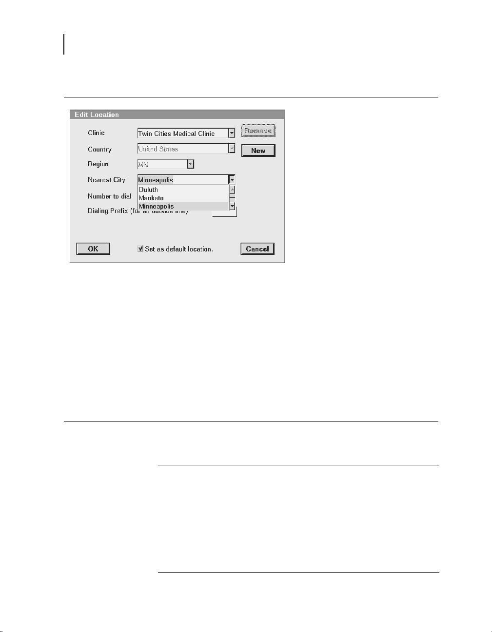
Editing Locations
Part of the dial-up software download process involves confirming
the programmer location on the Update Software screen. If the
clinic location does not appear in the clinic location pull-down
menu or if information about an existing location needs to be
changed, choose the <Edit Locations> selection from the
pull-down menu.
Programmer Reference Guide
Page 42

42
Chapter 3
Connecting to the SDN using a dial-up connection
The following procedures describe how to create a new location,
make changes to an existing location, or remove a location from
the programmer.
To create, edit or remove a location, you must be on the Update
Software screen. Note that the Update Software screen appears
as one of a series of screens that are accessible only during the
software update process.
Programmer Reference Guide
Page 43

Updating programmer software using the Software Distribution Network
How to create a new location
43
Connecting to the SDN using a dial-up connection
1. Using the clinic pull-down
menu, select Edit Locations.
When the Edit Locations screen
appears, click on [New].
2. When the new dialog window
opens enter the name of the
location.
3. Using the pull-down menus,
identify the location by selecting
the Country, Region, and
Nearest City.
4. Using the pull-down menu for
Number to dial, select the
number that will be dialed to
access the SDN.
5. In the Dialing Prefix field, enter
the digits of a dialing prefix, if a
prefix is required to access an
outside line.
6. To set this location as the
default location on the Update
Software screen, click on Set
as default location.
7. Click on [OK] to save this
location information.
8. When the Update Software
screen is redisplayed, select the
clinic and click on [Start] to
begin the download process or
click on [Cancel] to exit from the
download operation.
Programmer Reference Guide
Page 44
44
Chapter 3
Connecting to the SDN using a dial-up connection
How to change location information
1. On the Edit Location screen use
the pull-down menu to select an
existing location. Then,
beginning with the Nearest
City, use the pull-down menu to
select a different city if it needs
to be changed.
2. To select a different SDN
access number, use the
pull-down menu opposite the
Number to dial field. The list of
SDN access numbers shown is
based on the Nearest City
selected.
3. In the Dialing Prefix field, enter
the digits of a dialing prefix, if a
prefix is required to access an
outside line.
4. To set the currently displayed
location as the default location
on the Update Software screen,
click on Set as default
location.
5. Click on [OK] to save this
location information.
6. When the Update Software
screen is redisplayed, select the
clinic and click on [Start] to
begin the download process or
click on [Cancel] to exit from the
download operation.
Removing a location
Programmer Reference Guide
1. On the Edit Location screen use the pull-down menu to select the
name of the clinic you wish to remove from the programmer.
2. Click on [Remove].
3. Click on [Yes] to confirm the deletion.
4. On the Edit Location screen, select the clinic to be used from the
pull-down menu, then click on [OK].
5. When the Update Software screen is redisplayed, click on [Start] to
begin the download process or click on [Cancel] to exit from the
download operation.
Page 45

Updating programmer software using the Software Distribution Network
Connecting to the SDN using a wired network connection
Connecting to the SDN using a wired network connection
You can connect to the SDN using the combo card or integrated
Ethernet and your clinic’s network. By connecting through your
network, software download time can be significantly reduced.
Before you begin, make sure the Ethernet cable is correctly
connected to the combo card or integrated Ethernet. See
“Connecting the Ethernet cable” on page 34.
How to connect to the SDN using a network connection
1. Tap the Programmer icon.
Note: The SDN cannot be
accessed from Vitatron
screens. Change to the
Medtronic Select Model screen.
2. Select Software from the
menu.
The programmer displays the
Software on This Programmer
screen and lists the software
already installed on the
programmer. For each model,
the screen displays the software
version.
3. Select [Install from
Medtronic...].
Press [Accept] if you agree to
the terms of the installation
agreement. The download will
begin.
or
Press [Cancel] if you do not
agree to the terms. The
download process will be
cancelled and the programmer
will redisplay the Software on
This Programmer screen.
(Continued)
45
Programmer Reference Guide
Page 46

46
Chapter 3
Connecting to the SDN using a wired network connection
4. The programmer displays the
Scheduled Software Update
screen.
Either choose to start the download
at a particular time by selecting a
time from the Scheduled Update
Time pull-down menu, or begin the
download as soon as possible by
pressing [Start].
5. The Scheduled Software Update
window displays a countdown
window showing how much time
remains until the countdown
begins. Press [Start Now] to
override the countdown or press
[Cancel] to interrupt the countdown
and the download request and
return to the Software on This
Programmer screen.
6. The programmer displays a list of
software that will be downloaded
and installed.
Note: Individual software cannot be
selected or rejected.
You may press [Stop] at anytime
and resume the download at a
future time.
7. When the download is complete,
the programmer disconnects from
the SDN, automatically reboots,
and displays a screen listing the
software that was downloaded.
8. To obtain technical manuals for the
new software see “Obtaining
technical manuals” on page 49.
9. Click on the Select Model icon.
The programmer is then available
for patient use.
Note: The first time the newly
downloaded software is accessed,
some additional installation steps
may be completed but these are
automatic and no user intervention
is required.
Programmer Reference Guide
Page 47

Updating programmer software using the Software Distribution Network
Connecting to the SDN using a wireless network connection
Connecting to the SDN using a wireless network
connection
You can connect to the SDN using your clinic’s wireless network.
Before you begin, make sure the wireless connection is correctly
configured see “Configuring the SessionSync wireless network
connection” on page 88.
How to connect to the SDN using a wireless network connection
1. Tap the Programmer icon.
Note: The SDN cannot be
accessed from Vitatron
screens. Change to the
Medtronic Select Model screen.
2. Select Software from the
menu.
The programmer displays the
Software on This Programmer
screen and lists the software
already installed on the
programmer. For each model,
the screen displays the software
version.
3. Select [Install from
Medtronic...].Press [Accept] if
you agree to the terms of the
installation agreement. The
download will begin.
Press [Cancel] if you do not
agree to the terms. The
download process will be
cancelled and the programmer
will redisplay the Software on
This Programmer screen.
47
(Continued)
Programmer Reference Guide
Page 48

48
Chapter 3
Connecting to the SDN using a wireless network connection
4. The programmer displays the
Scheduled Software Update
screen.
Either choose to start the
download at a particular time by
selecting a time from the
pull-down menu, or begin the
download as soon as possible
by pressing [Start].
5. The Scheduled Software
Update window displays a
countdown window showing
how much time remains until
the countdown begins. Press
[Start Now] to override the
countdown or press [Cancel] to
interrupt the countdown and the
download request and return to
the Software on This
Programmer screen.
6. The programmer displays a list
of software that will be
downloaded and installed.
Note: Individual software
cannot be selected or rejected.
You may press [Stop] at anytime
and resume the download at a
future time.
7. When the download is
complete, the programmer
disconnects from the SDN,
automatically reboots, and
displays a screen listing the
software that was downloaded.
8. To obtain technical manuals for
the new software see
“Obtaining technical manuals”
on page 49.
9. Click on the Select Model icon.
The programmer is then
available for patient use.
Note: The first time the newly
downloaded software is
accessed, some additional
installation steps may be
completed but these are
automatic and no user
intervention is required.
Programmer Reference Guide
Page 49

Updating programmer software using the Software Distribution Network
Obtaining technical manuals
Medtronic technical manuals, including the one you are reading,
are available in a number of different formats from the Medtronic
eManuals website at www.medtronic.com/manuals. The
website offers real-time access to the latest version of manuals 24
hours per day, seven days per week. Manuals can be viewed
online, downloaded and then viewed or printed on a local printer,
or ordered from the website.
All manuals are available online in English. Most manuals are also
available in additional languages in online, CD-ROM, or a paper
format. New manuals are added to this site regularly. If you do not
find the manual you want, please contact your Medtronic
representative.
Medtronic will ship your order for CD-ROMs or printed versions of
manuals from our facility within 24 hours. Your order should reach
you within three business days. If you need a copy before the
shipment arrives, download the manual and print it, or contact your
Medtronic representative.
49
Obtaining technical manuals
Accessing the eManuals website
1. Point your browser to the following URL:
www.medtronic.com/manuals
2. Those accessing the website from the United States will just need
to click on [OK]. Anyone outside of the US will need to indicate they
are outside of the US and select a language preference.
3. To see lists of CRDM manuals, click on the desired category on the
left of the screen. You can also search for manuals using a product
name or model number.
Programmer Reference Guide
Page 50

Page 51

Conducting a patient session4
Preparing for a patient session 52
Initiating a patient session 62
Ending a patient session 66
Storing components 67
4
Page 52

52
Chapter 4
Preparing for a patient session
Preparing for a patient session
Familiarize yourself with the following information before
beginning a patient session:
■
Connecting the programmer to skin electrodes
■
Using the touch pen
■
Using the keyboard
■
Positioning the programming head
■
Emergency VVI button
Connecting the programmer to skin electrodes
At the start of each patient session, ECG cable leads must be
connected to the patient to detect cardiac and pulse artifact
signals.
Note: The quality of disposable skin electrodes used with the
programmer is important to the performance of the programmer
signal sensing functions. Chemical reactions occur at the
electrode/paste interface and produce small DC voltages that can
block the ECG signal. Using high quality silver/silver chloride
(Ag/AgCl) electrodes can minimize this problem. Electrodes
should be fresh and from the same box. The patient’s skin should
be prepared according to the directions provided with the
electrodes.
Protocols covering attachment of leads to disposable skin
electrodes may vary. Leads may be attached to the electrodes
either before or after the electrodes are applied to the patient. The
order of the procedure given below is arbitrary.
Programmer Reference Guide
Warning: Do not connect the programmer to wires or
electrodes internal to the body. The programmer is designed
to be medically safe only when attached to surface
electrodes.
Page 53

Attaching electrodes
Conducting a patient session
Preparing for a patient session
1. Attach five standard, disposable electrodes
to the patient in the positions shown.
53
Programmer Reference Guide
Page 54

54
Chapter 4
Preparing for a patient session
Connecting the ECG cable
1. As shown, attach a color-coded lead
wire to each of the five electrodes.
Match a color to each electrode as in
Ta bl e 4 -1 .
R N C F L
Note: Connecting the chest lead is
optional. If the chest lead is not
used, insert the chest ECG plug into
the middle cable port of the
ECG cable.
RA RL V LL LA
Tab le 4- 1. Electrode lead wire color coding
AHA Coding
a
Black Yellow to left arm
Red Green to left leg
Brown White to left chest area
Green Black to right leg
2. Connect each lead wire to the ECG
cable as in Table 4-2. Match each lead
connector to the proper cable port.
IEC Coding
b
Body Area
c
White Red to right arm
a
b
c
chest ECG plug into the middle cable port of the ECG cable.
Tab le 4- 2. ECG cable color coding
AHA Coding IEC Coding
Black to LA Yellow to L
Red to LL Green to F
Brown to V
Green to RL Black to N
White to RA Red to R
a
Programmer Reference Guide
American Hospital Association
International Electrotechnical Commission
Connecting the chest lead is optional. If the chest lead is not used, insert the
a
Labeled C on some cables
White to C
Page 55

Note: Occasionally, mutual interference occurs between the
programmer skin electrode signals and signals from an external
ECG recorder or monitor attached directly to the patient. This
interference may cause erratic operation of the programmer
functions that depend on surface signal detection. If interference
occurs, the leads from the attached ECG recorder or monitor
should be temporarily disconnected. This interference does not
affect the programming functions of the programmer.
Using the touch pen
The touch pen is used to select programming functions provided
by the software. Proper use of the pen is described below in
Figure 4-1 and in “Selecting an option on the screen” on page 56.
Figure 4-1. Using the touch pen
Conducting a patient session
Preparing for a patient session
55
I
V
V
Programmer Reference Guide
Page 56

56
Chapter 4
Preparing for a patient session
Selecting an option on the screen
1. Move the tip of the pen to a position
directly over the desired option.
While positioning the pen, do not press
it against the screen. Hold the pen
perpendicular to the screen. The pen tip
should be close to the screen.
If the desired option is a displayed key
or “button”, position the pen tip within
the rectangular outline.
If the desired option is a name or
number, such as a parameter or
parameter value, position the pen
directly over the letters or numbers
forming the option
2. Touch the pen to the screen to select an
option.
Programmer Reference Guide
Page 57

Using the keyboard
Conducting a patient session
Preparing for a patient session
Certain fields on the screen allow you to enter data, such as the
patient’s name or chart number. The programmer has a compact
computer keyboard for entering data.
Figure 4-2. Programmer keyboard
57
Positioning the programming head
At some point during most applications of the programmer, the
programming head must be positioned over the implantable
device. Positioning the programming head is required for any
interaction between the programmer and the implantable device.
When to position the programming head
Caution: Do not position the programming head over an
implanted device during electrocautery or external
defibrillation procedures.
During a patient session, properly position the programming head
over the implanted device before any of the following actions:
■
Selection of any command that initiates a programming
transmission. The programming head must be held in position
until completion of the transmission, which is usually indicated
by a confirmation message.
Programmer Reference Guide
Page 58

58
Chapter 4
Preparing for a patient session
■
Selection of any command that initiates data transmission
from the implantable device. The programming head should
be held steady until data reception is complete, which is
usually indicated by a confirmation message.
■
Selection of a measurement function that requires the
implantable device to be operating asynchronously as a result
of the programming head magnet.
For any temporarily programmed state or function or for reception
of continuous data such as Marker Channel telemetry or EGM
waveforms, the programming head must be held in place over the
implantable device for the duration of the function or until
termination is desired. Lifting the programming head cancels a
temporary program and terminates continuous telemetry. The
implantable device reverts to permanently programmed values.
Programmer Reference Guide
Page 59

Determining the correct position
For an implantable device, the programming head should be held
directly against the patient’s skin. The face of the programming
head must be parallel to and typically within 2 inches of the
implantable device. Optimum position of the programming head
may not be directly centered over the implantable device.
Figure 4-3. Positioning the programming head
Conducting a patient session
Preparing for a patient session
59
Light Array
2
Correct placement of the programming head is indicated in two
places: the position head array in the top left corner of the screen
and the array of seven lights on the programming head (see
Figure 4-3).
Programming and Interrogation are not recommended when
less than two green lights are on.
Programming and interrogating the implanted device
1. Select the appropriate software parameters according to the
reference guide.
2. Position the programming head near the implantable device.
Programming and Interrogation can begin when the position
head array turns green.
Green
Amber/Green
Programmer Reference Guide
Page 60

60
Chapter 4
Preparing for a patient session
Using the P and I buttons
Note: For Medtronic devices, the position head array shows the
signal strength of the communication link. Moving the
programming head to maximize the number of green lights is
recommended. All lights may not illuminate for all models (see the
reference guide for the implanted device).
Note: Vitatron and Reveal Plus devices may turn one light in the
position head array to green when the programming head is in the
correct position rather than indicating the signal strength.
Note: Misalignment of the programming head could result in
failure of a programming transmission and/or failure to receive
data from the implantable device.
The P button and I button on the programming head (Figure 4-4)
correspond to commands that appear on the display screen of the
programmer. Refer to the appropriate reference manual to
determine which commands the buttons correspond to. For
convenience, you may press the P button or the I button on the
programming head in place of selecting the corresponding option
from the display.
Figure 4-4. P and I buttons
Programmer Reference Guide
P Button
I Button
Page 61

The programming head magnet
A strong magnet in the programming head actuates a sensor in
the implantable device, which makes the implantable device
receptive to programming (refer to the reference guide for the
implanted device for more information about the effects of a
magnet).
Be aware that the programming head may attract metal
instruments or be attracted to metal surfaces. The magnet is
susceptible to partial demagnetization when it is subjected to
opposing magnetic fields - that is, forcing the programming head
against another magnet.
The programming head should be kept away from any device or
material that will be damaged by the magnetic field, including
computer diskettes. The programming head should be stored as
shown in Figure 4-6 on page 67 when not in use.
Emergency VVI button
The Emergency VVI button on the display panel provides ready
access for emergency procedures (Figure 4-5) during a session. It
is important to understand its operation before programming the
patient’s implantable device. For a detailed explanation read the
reference guide for your specific implantable device.
Conducting a patient session
Preparing for a patient session
61
Note: The Emergency VVI button is also implemented in the
software and appears on the display. It functions similarly to the
button on the panel.
Warning: The red Emergency VVI button is disabled for the
following devices: PCD, Jewel PCD, Micro Jewel II,
MicroJewel, Jewel CD, Jewel Plus, Model 7202 Jewel CD,
Models 7218 and 7211, Model 7201 CD, and Jewel AF. Use
the touch pen to select the on screen [Emergency] button.
Bradycardia (Medtronic and Vitatron): After correctly
positioning the programming head, press the Emergency button.
Tachyarrhythmia: See the 2090 Software Supplement and the
reference guide for the implanted device.
Programmer Reference Guide
Page 62

62
Chapter 4
Initiating a patient session
Figure 4-5. Emergency button
VVI
Emergency VVI
Button (Red)
Initiating a patient session
A patient session involves the application of the various
programmer functions to such procedures as programming
implantable device parameters, analyzing or assessing
implantable device operation, troubleshooting, and routine
follow-up. The instructions for using each programmer function are
covered in the reference guide for the implanted device.
Note: Before proceeding, ensure that all preparations covered in
Chapter 2, “Setting up the programmer” on page 29 and
“Preparing for a patient session” on page 52 have been
completed.
Programmer Reference Guide
Page 63

Programmer checklist
1. Is the programmer set up according to the procedures in
2. Are the ECG cable, touch pen, and programming head connected
3. Does the power cord connect the programmer to an AC power
4. Has the appropriate software been installed? Refer to Chapter 6
5. Are the programmer ECG cable leads connected to electrodes on
Specific information related to each implantable device model or
family of models is included in the reference guide for the device.
Refer to the reference guide for the implanted device before
beginning a patient session.
Model identification
Conducting a patient session
Initiating a patient session
Chapter 2?
to the programmer?
outlet?
for a description of how to verify the software version and refer to
Chapter 3 to update software, if necessary.
the patient as described in Chapter 4?
63
Because the programmer collects and stores data on a
session-by-session basis, it is important to correctly start and end
each session.
The programmer supports both a Medtronic and Vitatron desktop.
Whichever desktop is in use when the programmer is powered
down, that same desktop will appear when the programmer is
powered on. To switch from the Vitatron desktop to the Medtronic
desktop and vice versa, select the Vitatron/Medtronic switch
button that appears on the bottom of the screen.
There are two ways to begin a patient session:
■
Prior to turning on the programmer, position the programming
head over the patient’s device. When you turn on the
programmer, the programmer will attempt to interrogate the
device. Depending on the device, either the software
application will be launched automatically or a message will
appear with further instructions.
Programmer Reference Guide
Page 64

64
Chapter 4
Initiating a patient session
■
After turning on the programmer, position the programming
head over the patient’s device. During the first five minutes, the
Medtronic desktop will display the Find Patient screen.
Afterward, it displays the Select Model screen. The Vitatron
desktop displays the Select Model screen immediately. A
patient session can begin at either the Find Patient screen or
the Select Model screen. Follow the instructions that follow,
based on the screen that is displayed.
Find Patient screen
When the programmer is first turned on, the Medtronic desktop
displays the Find Patient screen. After about five minutes, the Find
Patient screen is replaced by the Select Model screen.
When the Find Patient screen is displayed you may begin a patient
session.
Place programming head over the patient’s device and hold it
steady. For most devices, the programmer will identify the device
model and automatically start up the proper software application.
If a device cannot be automatically identified, the programmer
displays a message at the top of the Find Patient screen. The
message will provide further instructions:
Programmer Reference Guide
■
Select cancel and manually select the software application
from the Select Model screen.
Page 65

Conducting a patient session
Initiating a patient session
■
Select cancel and then select the Vitatron/Medtronic switch
button to go to the Vitatron desktop, or
■
Indicate that the software application that is needed has not
been installed. You will need to install the software before
proceeding. Refer to Chapter 3 for software installation
instructions.
Select Model screen
A patient session may also begin from the Select Model screen.
The Select Model screen appears:
■
Shortly after the programmer has been turned on.
■
After you end a patient session.
If the Select Model screen is not displayed, use the touch pen to
select the Select Model icon. If the Select Model icon is not
displayed, a patient session is in progress. You must end that
session before starting a new one.
If you are between patient sessions, you can access other screens
by using the icons and buttons described in Chapter 6.
65
If the device is a Vitatron device and it is not listed on the Select
Model screen, refer to the Vitatron Software Programming Guide.
Programmer Reference Guide
Page 66

66
Chapter 4
Ending a patient session
If the Select Model screen does not look like this example and you
see a button, select the Vitatron/Medtronic switch
button to display this screen.
Position the programming head over the patient’s device and hold
it steady. Select [Find Patient] shown on the Medtronic desktop or
manually select the device from the displayed list of devices and
select [Start].
When a device is manually selected from the list of devices, the
programmer starts up the application that corresponds to your
selection, not the device that is under the programming head. The
Find Patient screen quickly displays as the programmer starts up
the proper software application.
If the software application has not been installed, the programmer
displays a message and you will need to install the software before
proceeding. Refer to Chapter 3 for software installation
instructions.
Note: If your device does not support concurrency, you must exit
the Analyzer before you can start a device session. That is, if you
use the task bar to switch from the Analyzer to the Select Model
screen and then select [Find Patient], the programmer will display
the following message:
This application is not able to run concurrently with the
Analyzer. Please exit the Analyzer and try again.
The programmer may automatically interrogate the patient’s
implanted device to retrieve most of the data that might be needed
during the session. To take advantage of this automatic
interrogation, you must position the programming head over the
implanted device and continue to hold it in place until the
interrogation is complete.
Refer to the reference guide for the implanted device for more
information about determining the model.
Ending a patient session
When you want to end a patient session there are three options.
You may save data to a disk, save to SessionSync, or end the
session without saving.
Please refer to the reference guide for the implanted device for
specific information on saving device data.
Programmer Reference Guide
Page 67

Storing components
The following diagrams show the proper way to store components
(Figure 4-6).
Figure 4-6. Storing components
Conducting a patient session
67
Storing components
I
V
V
Programmer Reference Guide
Page 68

Page 69

Using external printers 70
Installing printer paper 72
Printer buttons 73
Tearing off a printout 74
Low paper supply 74
Using printers5
5
Page 70

70
Chapter 5
Using external printers
Using external printers
Connecting a compatible printer to the programmer allows you to
print full, page-size reports of session data when available (see
the reference guide for the implanted device). This section
describes how to connect a printer to your programmer.
All printers listed by this software are certified to IEC 60950,
UL 60950 or equivalent. Only printers listed by this software may
be connected to the programmer. It is the responsibility of the user
to keep the printer at least two meters away from the patient.
Printer compatibility
The programmer is compatible with many printers. A list of
compatible printers can be accessed from the Print Queue screen.
Note: When programming a Vitatron device, refer to the
applicable Vitatron reference guide for information about the print
queue.
To view a list of supported printers
Some devices only support the internal programmer printer and
the print queue window shown below cannot be displayed. Refer
to the applicable device reference guide.
For those devices that support an external printer, refer to the
following procedure.
Programmer Reference Guide
1. If you are conducting a
patient session, select
Reports then
Print Queue.
If you are not
conducting a patient
session, select the
Print Queue icon.
2. On the Print Queue
screen, select the
2
Printer field to open the
list of supported
printers.
Page 71

Materials you will need
To connect a printer to the programmer you will need a USB
printer cable. One end must be a USB Type A connector. The
other end of the cable must fit the USB port on your printer.
Connecting the printer
Prior to connecting a printer to your 2090 programmer, you should
exit the patient session and turn the programmer off.
To connect the printer to your 2090 programmer
1. To connect a printer, locate the correct port. There is one USB port
located under the disk drive, PC card cover and two ports located
under the power cord door on the back of the programmer.
2. Connect the printer cable to a USB port on the side or back of the
programmer.
3. Connect the other end of the cable to the printer. Connect the
printer power cord to an outlet and turn the printer on. Make sure
that the printer has paper.
Note: Refer to the technical information provided with your printer
for information about connecting and operating the printer.
4. Turn the programmer on and select the Print Queue icon.
Note: Be sure to select the correct printer driver from the options
listed when you select the Printer field on the Print Queue window.
You are now ready to use your programmer with the connected
printer.
Using printers
Using external printers
2
71
Programmer Reference Guide
Page 72

72
Chapter 5
Installing printer paper
Installing printer paper
How to load printer paper
The internal printer requires a special thermal paper supplied in
flat packs. You may obtain this paper directly from Medtronic or
Vitatron. One package of printer paper contains six individual
packs of paper. Each pack contains approximately 200 perforated
sheets.
1. Press the latch on the top of the tray on the left side of the
programmer. Slide the tray out. Flip the paper holder over the
end of the tray and remove any remaining paper.
Note: The tray may be taken out of the programmer to make
removing any remaining paper easier. Press down on the
lever on the side of the tray towards the front of the
programmer.
2. Remove the wrapping from a new flat pack of printer paper,
dispose of the cardboard and unfold the top sheet.
Note: The shiny side of each sheet of paper with two black
squares should be facing up as the paper is loaded into the
tray. The black squares must be positioned toward the front
of the programmer
3. Slide the paper pack toward the back of the tray. Flip the
paper holder over the paper pack.
4. Fold the top sheet of paper over the paper holder. Slide the
tray back into position.
Programmer Reference Guide
Page 73

Printer buttons
Using printers
Printer buttons
The four buttons shown below control certain printer functions.
Figure 5-1. Printer buttons
1
2
3
4
73
1 50 mm/s
2 25 mm/s
3 12.5 mm/s
4 Paper Advance
50, 25, or 12.5 mm/s. – Three buttons allow for selection of a
desired paper speed for ECG, Marker Channel telemetry, and
EGM recording. Pressing a button selects the printer speed and
turns on the indicator light. Pressing a lit button stops the printout.
The selected paper speed is printed once along the top edge of
the chart recording. Paper speed for text printing is not affected by
these buttons.
Paper Advance – Pressing Paper Advance advances the printer
paper to its next perforation for tearing off.
Programmer Reference Guide
Page 74
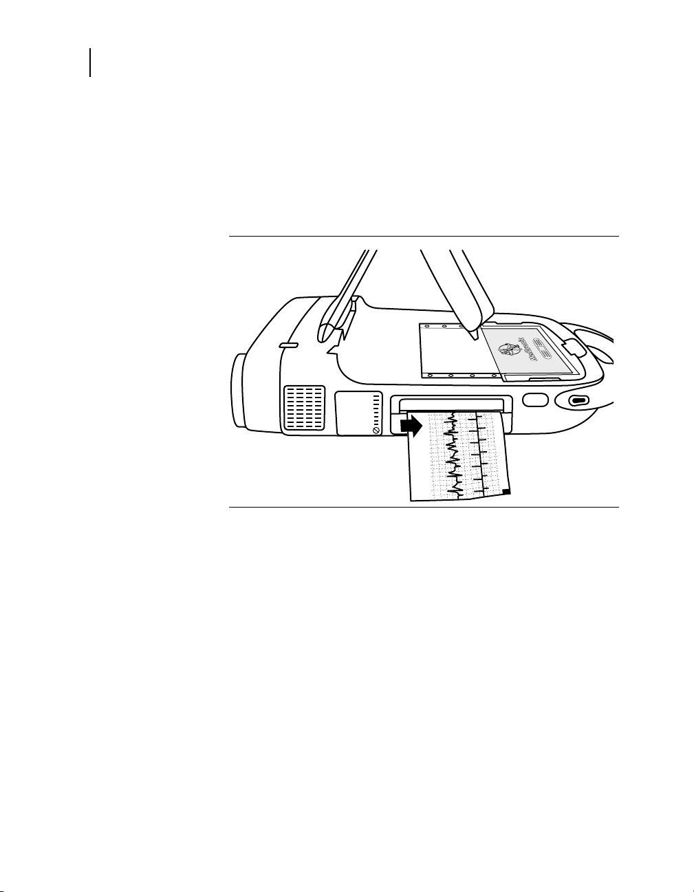
74
Chapter 5
Tearing off a printout
Tearing off a printout
When you wish to tear off a printout, separate the paper strip at a
perforation. To tear the printout off at the printer, press Paper
Advance. This action advances the paper to the next perforation.
Grasp the printout an inch or two from the printer and pull.
Figure 5-2. Tearing off printouts
Low paper supply
As the paper supply nears its end, a red stripe will appear along
the edge of the paper. At this point, a new paper pack should be
installed as previously described in this chapter. When the paper
supply runs out, the printer stops operating.
Note: The thermal paper used in this programmer is intended for
immediate use. As the quality of thermal paper diminishes over
time, the image fades. Medtronic and Vitatron recommend that
you make photocopies for your files.
Programmer Reference Guide
Page 75

Setting desktop preferences6
About the between sessions tool palette 76
Adjusting programmer time and date 78
Selecting audible tones 79
Changing the language setting 80
Improving the detection of pacing artifacts 80
Checking the software version 81
Starting the demonstrations option 82
Viewing and updating programmer location and hardware information 82
Selecting other software 84
6
Page 76

76
Chapter 6
About the between sessions tool palette
About the between sessions tool palette
The between sessions tool palette is on the Select Model
screen.The Select Model screen appears before you select a
model, when you turn the programmer on, and when you end a
patient session.
The tools that are available between sessions are described in
Ta bl e 6 - 1.
Note: When programming a Vitatron device, refer to the
applicable reference guide for information about the tool palette.
Programmer Reference Guide
Page 77

Setting desktop preferences
About the between sessions tool palette
Tabl e 6 -1 . Between Patient Sessions tool palette
Tool palette Tool Selecting the tool (button or icon)…
Freezes a segment of the live rhythm display.
Note: A frozen strip can be viewed and printed (but not
saved) between patient sessions. Markers and EGM traces
are not present between patient sessions.
Accesses the rhythm strips saved during a patient session.
Note: No saved strips are available between patient
sessions.
Opens a window of options for adjusting the live rhythm
display.
Note: Additional adjustment options are present during a
patient session.
Displays the screen for selecting a model and starting a
patient session.
Displays a queue of print requests from previous sessions as
well as frozen waveform reports requested between sessions.
Refer to the reference guide for the implanted device to
determine if these features are available.
77
Displays the programmer setup options.
Preferences
Time and Date
Artifact Detection
Software
Demonstrations
Programmer Profile
Other Software
Selects the Analyzer for analyzing the electrical performance
of a cardiac lead system (requires optional hardware - see the
2290 Analyzer Reference Guide.)
Note: When some functions are active on the display, selecting a
tool button or icon will have no effect. Closing the active window
restores operation of the tool palette.
Programmer Reference Guide
Page 78

78
Chapter 6
Adjusting programmer time and date
Adjusting programmer time and date
If the time or date displayed and printed by the programmer is
incorrect, use the following procedure to enter the correct settings.
For Vitatron devices, see the applicable reference guide.
Setting the time and date
1. Select Programmer then
Time and Date.
2. From the Programmer
Time and Date screen,
select the or button
to increase or decrease
the value for the unit of
time you want to change.
Press and release the
button for single unit
changes or press and
hold the button to effect
greater changes.
3. When all fields show the
correct time and date,
press [Apply]. Select
another tool palette icon
to close the Programmer
Time and Date window.
Programmer Reference Guide
Note: Time must be entered on the basis of a 24-hour clock,
with 00:00 being midnight and 12:00 being noon.
Page 79

Selecting audible tones
Certain events in the operation of the programmer result in an
audible signal. The following tones alert the user to the success or
failure of an action.
■
A two-tone beep (low-to-high) indicates confirmation of an
Interrogate or a Program command.
■
A double low-tone beep indicates that an Interrogate,
Program, or Emergency command was not confirmed. It can
also indicate that the selected command cannot be executed.
Note: For some devices, the tones may not be turned off. See the
reference guide for the implanted device. For Vitatron devices,
see the applicable reference guide.
Turning tones on or off
Setting desktop preferences
Selecting audible tones
1. Select Programmer then
Preferences.
2. From the Preferences
screen, select [Audio ON]
or [Audio OFF] as desired.
79
Programmer Reference Guide
Page 80

80
Chapter 6
Changing the language setting
Changing the language setting
The software is translated into several languages. Use the
following procedure to determine which languages are available.
For Vitatron devices, see the applicable reference guide.
Choosing a language
1. Select Programmer then Preferences.
2. From the Preferences screen, select the Language field to display
the options.
Improving the detection of pacing artifacts
The Artifact Detection function allows one to improve the detection
of pacing artifacts when interference causes either false artifacts
or no artifacts to appear on the patient’s ECG. Pacing artifacts are
displayed on the patient’s ECG when the artifact detection option
(Show Artifacts) has been enabled.
See the reference guide for the implanted device to determine if
this feature is applicable.
Enabling artifact detection
1. Select Programmer then Artifact Detection.
2. Select the filter on option.
For information on using the Artifact Detection function, see the
reference guide for the implanted device.
Programmer Reference Guide
Page 81

Checking the software version
This section describes how to determine the version of software
that is loaded on the programmer.
If you need to know what version of software is currently loaded on
the programmer for any of the device models, use the following
procedure.
For Vitatron devices, see the applicable reference guide.
To check the software version number
Setting desktop preferences
Checking the software version
1. Select Programmer then
Software.
2. For each device model with
software loaded on the
programmer, the screen
displays the software version
number next to the model
number.
81
Note: If the model that interests you is not displayed, the software
to support that model is not currently loaded on the programmer.
Refer to “The Software Distribution Network” on page 38 for
instructions.
Programmer Reference Guide
Page 82

82
Chapter 6
Starting the demonstrations option
Starting the demonstrations option
The demonstrations option allows you to run a demonstration
program on the programmer. Refer to the demonstration
instructions that accompany the program diskette for specific
operating procedures.
For Vitatron devices, see the applicable reference guide.
Accessing demonstrations
1. Select Programmer then Demonstrations.
2. Insert the demonstration diskette into the disk drive.
3. From the Demonstration Model Selection screen, select the
desired View option to list the available demonstration programs.
4. Select the desired demonstration program and press [Start]
followed by [Continue].
Viewing and updating programmer location and hardware information
Information about the location of the programmer and its hardware
is on the Programmer Profile screens.
The Programmer Profile location screen has the following
information:
■
Clinic’s name, address, phone number, contact person, and
customer account number
■
Service representative’s name, phone number, fax number,
and E-mail address
The Programmer Profile hardware screen has model and serial
numbers for the programmer, the programming head, and the
Analyzer.
Information on the screen may be updated by selecting the
appropriate field and then using the keyboard.
Programmer Reference Guide
Page 83

Viewing and updating programmer location and hardware information
Accessing Programmer Profile screens
1. Select Programmer then Programmer Profile. Location
information appears by default.
2. To view hardware information, select Hardware Information.
Verifying Programmer Profile information
Each programmer has a profile screen that contains identifying
information about the installed hardware, the programmer’s
location and contact information for the Medtronic or Vitatron
service representative.
Typically, the profile is completed when the programmer is first
installed and then updated only when necessary. Although it is not
required to check the profile prior to each software download, it is
a good practice to periodically verify that the information on the
Programmer Profile screen is complete and accurate before
connecting to the SDN.
Setting desktop preferences
1. Tap the Programmer icon and
then select Programmer
Profile.
2. Complete the location
information or verify that the
information shown is correct.
83
Programmer Reference Guide
Page 84

84
Chapter 6
Selecting other software
Selecting other software
In addition to the standard application software, there are some
programmers that have special applications installed. These
special applications are considered research software and are
used in conjunction with clinical studies. If you have this research
software installed, you may access the software, using the
following procedure.
1. Select Programmer then Other Software.
2. When the programmer displays the list of available software, select
the application and press Start.
Programmer Reference Guide
Page 85

SessionSync 86
Optional Software Features7
7
Page 86

86
Chapter 7
SessionSync
SessionSync
SessionSync provides network connectivity between the 2090
programmer and the Medtronic Paceart data management
system. Using your clinic’s network, the programmer can send
downloaded device data through SessionSync to the data
management system.
The SessionSync status icon and the SessionSync status screen
provide information on the connection status of the programmer to
the data management system.
You must configure the programmer’s network settings to allow for
this data transfer.
This section describes:
■
Configuring the SessionSync network connection
■
Configuring the SessionSync wireless network connection
■
Enabling and disabling SessionSync
■
Viewing SessionSync Status
■
States of the SessionSync Status icon
Programmer Reference Guide
Page 87

Optional Software Features
Configuring the SessionSync wired network connection
See “Connecting the Ethernet cable” on page 34 for instructions
on connecting the programmer to the network.
1. Select Programmer >
SessionSync Network
Configuration...
2. Enter the Clinic Name.
3. Enter the IP address or
hostname of the
SessionSync Gateway.
Note: If you do not have
your SessionSync
Gateway address, contact
your clinic’s technical
support or Medtronic
Paceart technical support
at 1-800-PACEART.
4. Select [OK].
87
SessionSync
Programmer Reference Guide
Page 88

88
Chapter 7
SessionSync
Configuring the SessionSync wireless network connection
Make sure your Wireless card is properly installed before
you begin.
1. Select Programmer >
SessionSync Network
Configuration...
2. Enter the Clinic Name.
3. Enter the IP address or
hostname of the
SessionSync Gateway.
Note: If you do not have
your SessionSync
Gateway address, contact
your clinic’s technical
support or Medtronic
Paceart technical support
at 1-800-PACEART.
4. Enter the Network Name.
5. Enter and confirm your
Network Key.
6. Select [OK].
Enabling and disabling SessionSync
Programmer Reference Guide
1. Select Programmer >
Preferences.
2. Select SessionSync from
the Index menu.
3. Select [Enabled] to enable
SessionSync or Select
[Disabled] to disable
SessionSync.
Note: The SessionSync
icon will be grayed out
when the feature is
disabled. Within a patient
session, the SessionSync
functions are not available.
SessionSync cannot be
used until you have ended
the session and re-enabled
the feature.
Page 89

Viewing SessionSync Status
The SessionSync Status screen displays information on the data
files being transferred to the data management system using
SessionSync. Each message includes the date, time, and event
information for the associated SessionSync event.
Note: SessionSync data transfer may be delayed during an
electrosurgical procedure.
How to view SessionSync status
Optional Software Features
SessionSync
1. Select Programmer >
SessionSync Status.
2. Select [Update Status].
89
Note: SessionSync status does not dynamically update when the
window is open. To update select the [Update Status] button.
SessionSync Status icon
The SessionSync status icon provides information on the network
connection between the 2090 programmer and the data
management system.
Programmer Reference Guide
Page 90

90
Chapter 7
SessionSync
Figure 7-1. The task bar with the SessionSync Status icon
1
1 The SessionSync Status icon
If SessionSync is not installed on the programmer, the icon will not
be visible in the task bar.
Note: This icon will be grayed out (disabled) for any Vitatron
desktop application or any Vitatron device application.
Figure 7-2. Parts of the SessionSync Status icon
3
2
1 The programmer status
2 The connection status between the programmer and the data management system
3 The data management system status
1
The sections of the SessionSync Status icon will change colors to
indicate data ready for transfer, a valid connection between the
programmer and the data management system, and successful
data transfer to the data management system.
Note: When the whole icon is grayed out, SessionSync has been
disabled under the programmer preferences.
Tab le 7- 1. SessionSync Status icon states
Part of SessionSync
Status Icon
Programmer Gray No session data files are in
Color What the color indicates
the Transfer Queue. The
transfer queue is the list of
session data files that have
been saved to the
programmer’s hard disk but
are waiting for transfer.
Programmer Reference Guide
Blue Session data files exist in the
Transfer Queue
Page 91

Optional Software Features
Tabl e 7 -1 . SessionSync Status icon states
Part of SessionSync
Status Icon
Connection Not
Color What the color indicates
visible
91
SessionSync
No valid connection exists
between the programmer and
the data management
system
Green Valid connection exists
Red circle
with a line
through it
Data Management System Gray No session data has been
Blue All session data has been
between the programmer and
the data management
system
Device application in use
does not support
SessionSync
transferred to the data
management system
successfully transferred to
the data management
system
Programmer Reference Guide
Page 92

Page 93

Remote View basics 94
Starting a Remote View session 95
Ending a Remote View session 96
Using Remote View8
8
Page 94

94
Chapter 8
Remote View basics
Remote View basics
Remote View allows someone with a computer to see what is on
the programmer’s display. Only one computer at a time may show
what is on the programmer’s display. The computer cannot store
session data or perform programmer functions.
The computer that will be displaying the programmer screens will
need to have Remote View software installed and meet the
following requirements:
Tab le 8- 1. Computer requirements for Remote View
Hardware - Software Requirements
Computer IBM PS/PC with an Intel 80486 processor or
Modem Modem with support for the AT command set.
Video Any graphics adapter supported by Windows.
Disk Space 4.5 MB.
Software Windows 95, Windows 98, Windows NT
Important considerations
Caution: Slower modem connection speeds will cause longer
transmission delays of information between the programmer
and the remote computer.
■
The user of the Remote View software is responsible for
compliance with all applicable laws and regulations
concerning patient privacy, including but not limited to
maintaining the confidentiality of the viewed patient medical
information and restricting access to the computer containing
the software to those otherwise authorized to view patient
information.
■
The programmer user maintains control of the programming
session and the programming of the implanted device.
■
The remote computer user can only view what is on the
programmer’s display. They cannot save any session data or
perform any programming functions.
higher or 100% compatible. Recommended
16MB of available memory or higher.
3.51/4.0, Windows 2000, Windows Me.
Programmer Reference Guide
Page 95

■
The programmer’s modem, via the connection on the combo
card or modem card must be connected to an analog
telephone jack.
■
If your programmer has the wireless card installed, you must
remove the wireless card and use the combo card or modem
card. If you remove and insert another PC card you must
restart the programmer.
■
To SessionSync during the Remote View session you must
use the combo card and be connected to your wired network.
■
Ending the programming session automatically ends the
Remote View session.
■
The PC card should not be removed during a remote view
session.
Starting a Remote View session
The programmer’s modem must be connected to a telephone jack
to use the Remote View feature. See Figure 1-5 for the location of
the modem (You need a telephone and a second phone line to talk
to the consultant.).
Using Remote View
Starting a Remote View session
95
Caution: Slower modem connection speeds will cause longer
transmission delays of information between the programmer
and the remote computer.
Procedure for enabling Remote View
1. Select the Remote View icon in the task bar at the top of
the screen.
2. Call the person who is to view the programmer display on a
computer, on a second phone line. Ask the person to
connect with the programmer using Remote View software
and to talk during the session.
3. Wait for Remote View session to be enabled. When the
icon appears as shown on the left, Remote View is
enabled and can accept the incoming call for the Remote
View session.
Programmer Reference Guide
Page 96

96
Chapter 8
Ending a Remote View session
Ending a Remote View session
The computer can show what is on the programmer’s display until
the Remote View session or the programming session is ended.
Ending the programmer session will automatically end the remote
view session.
Procedure for ending Remote View
1. Select the Remote View icon in the task bar at the top of
2. Select the Yes option.
3. Wait for Remote View session to end. When the icon
the screen.
appears as shown at the left, the Remote View session
has ended.
Programmer Reference Guide
Page 97

Servicing the Programmer9
Cleaning the system components 98
Sterilizing the programming head, ECG cable, and lead wires 98
Replacing a PC card 99
Programmer specifications 100
Special notice 104
Medtronic limited warranty 104
9
Page 98

98
Chapter 9
Cleaning the system components
Cleaning the system components
The exterior surfaces of the programmer and its accessories may
be cleaned with a damp sponge or soft cloth moistened with water,
mild detergent, or alcohol. Care must be taken to prevent liquid
from entering the programmer and programming head.
Do not immerse the programmer or any accessories in any liquid
or clean them with aromatic or chlorinated hydrocarbons.
With the exception of the programming head and ECG leads
and cable, the programmer and its accessories cannot be
sterilized.
Sterilizing the programming head, ECG cable, and lead wires
Caution: Do not autoclave the programming head or ECG
cable and lead wires.
Ethylene-oxide
Note: The programming head or ECG cable and lead wires must
be completely dry before being ethylene-oxide sterilized.
Biological indicators should be used to ensure that proper
sterilization standards have been met. A previously validated
sterilization cycle should be used.
Due to the variability in sterilization systems, precise sterilization
instructions cannot be provided. Contact the manufacturer of your
sterilization system for more information regarding procedures.
Programmer Reference Guide
1. Wrap the programming head or ECG cable and lead wires in
packaging permeable to ethylene oxide.
2. Medtronic recommends that exposure to ethylene oxide is not to
exceed 3 hours and is followed by a minimum of 12 hours of
aeration.
3. Do not exceed 55
° C (131° F).
Page 99

Servicing the Programmer
Replacing a PC card
Gas plasma (programming head only STERRAD 100S gas plasma system)
1. Place the programming head in packing material appropriate for
gas plasma sterilization.
2. Sterilize by procedures validated for effectiveness using suitable
biological controls.
a. Do not exceed 55° C (131° F).
b. Do not use an H
c. Do not expose the programming head to a sterilizer cycle longer
than 72 minutes.
d. Do not resterilize more than five programming heads in one load
or combine them with other surgical instruments or devices in
the same load.
Visually inspect the cable and connections of the programming
head after sterilizing. Do not use the programming head if it
appears damaged. Damage includes, but is not limited to
deterioration of the cable insulation (brittleness, cracking, thinning,
or bare spots). Do not use the programming head if the conductive
wires are exposed.
concentration below 1 mg/L.
2O2
99
Replacing a PC card
Contact your Medtronic or Vitatron representative if you need to
replace a PC card in the programmer.
Note: It is not necessary to perform a safety check when a PC
card is inserted or replaced in the programmer.
Procedure for replacing a PC card
1. Turn off the programmer.
2. Open the disk drive/PC card cover door. See Figure 1-5 for the
location.
3. Remove the existing PC card.
4. Insert the new PC card. If you are installing the wireless card, insert
it into the top slot.
5. Turn on the programmer.
Programmer Reference Guide
Page 100

100
Chapter 9
Programmer specifications
Programmer specifications
Tab le 9- 1. 2090 Programmer specifications
Standards (The programmer complies with the following:)
EMC
Patient Safety
Voltage
Frequency
Power
Resolution
Paper Type
Waveform Recording
Speeds
Input Impedance at DC
ECG Range of
Linear Operation
ECG Total Signal Error
Pacing Pulse Width
EN 60601-1-2
UL/CUL 60601-1:2003, Class I, Type BF
ordinary EN 60601-1, Class I, Type BF,
continuous operation
Power requirement
100 to 125 VAC nominal or
200 to 240 VAC nominal
50/60 Hz nominal
400 watts
Printer
600 dots/25 mm horizontally for waveform
traces at print speeds through 25 mm/sec.,
400 dots/25 mm at 50 mm/sec.;
200 dots/25 mm vertically
110 mm wide, Thermal, Medtronic No. 6092
12.5, 25 or 50 mm/s
ECG specifications
>2.5 Me
- 5 mV to + 5 mV
< 10%
> 100 µs to 2 ms
Ω at 10 Hz
Height
Width
Depth
Weight
Operating
Storage
Programmer Reference Guide
Physical dimension and weight
12.7 cm (5 in) screen down, 48.2 cm (19 in)
screen up
40.6 cm (16 in)
55.8 cm (22 in)
11.3 kg (25 lbs), including modem
Temperature limits
9.4°C to 35°C (48.9°F to 95°F)
- 22°C to 60°C (- 7.6°F to 140°F)
 Loading...