

Page 1
Programming guide
Software version 9.1
Model VSA02 (for 9790c)
Model VSC02 (for Vitatron CareLink Programmer)
Caution: Federal Law (U.S.A.) restricts this device to sale or on the order of a
physician (or properly licensed practitioner).
Page 2

The following are trademarks of Vitatron B.V.:
Holding
Beat-to-Beat®Mode Switching, Sensor Blending®, Sensor Cross-Checking®, Clarity®,
®
Diamond
, Selection®, Ruby®,Topaz®, Jade®LegacyTMand Vita®.
Page 3

Table of contents
1. Introduction 3
2. The screen layout 5
2.1 The Vitatron desktop 5
2.2 General screen layout 7
2.3 Menu options 9
2.4 Vitatron desktop tutorial 10
2.5 Scrolling 19
3. Follow-up 21
3.1 Start-up and Auto-Identify 21
3.1.1 Start-up 22
3.1.2 Selecting Auto-Identify 23
3.2 How to use the built-in ECG recorder 26
3.2.1. Using the ECG in the Vitatron desktop 26
3.2.2. Using the ECG during follow-up 27
3.3 How to program a parameter 34
3.3.1 Parameter programming 34
3.3.2 Parameter pertinency 36
3.3.3 Batch programming 37
3.3.4 Nominal programming 38
3.3.5 Additional programming for the
Selection AFm 902 41
3.4 How to measure pacing thresholds 42
3.5 How to perform a sensing test 45
3.6 How to retrieve data 48
3.6.1 Status and Diagnostic Observations 49
3.6.2 Histograms 50
3.6.3 Holters 53
3.6.4 Mode Switching Trend 54
3.6.5 Selected Event Recording 55
3.7 How to set Diagnostic Features 57
3.7.1 Histograms or Holters 57
3.7.2 Mode Switching Trend 58
3.7.3 Selected Events 59
3.7.4 Additional Diagnostics for the
Selection AFm 902 59
1Programming Guide
Page 4

Table of contents
3.8 Results from Counters 66
3.9 Battery & lead data 67
3.10 How to print pacemaker data 68
3.11 How to save pacemaker data to diskette 70
3.12 How to enter patient data 71
3.13 How to temporarily program a parameter 76
3.14 How to set ECG markers 79
3.15 How to end a programming session 84
3.16 How to switch between Vitatron and
3.17 How to cancel/activate the programming
4. Programming reference 89
4.1 Programming the Clarity DDDR, Clarity SSIR,
4.2 Programming the Vita 2 DDDR and Vita 2 SSIR 101
4.3 Notes for Section 4.1 - 4.2 108
4.4 Programming the Selection AFm 902, Diamond,
4.5 Programming the Vita DDDR, Vita DDD
4.6 Notes for Section 4.4 - 4.5 151
Medtronic applications 86
head magnet 87
Diamond 3, Ruby 3, Topaz 3 and Jade 3 90
Diamond II,Ruby II, Topaz II and Jade II 134
and Vita VVIR 144
5. Appendices 177
5.1 Emergency operation 177
5.1.1 Emergency programming
during follow-up 177
5.1.2 Emergency programming
in the Vitatron desktop 178
5.1.3 Emergency settings 178
5.2 Adjusting programmer settings 181
5.2.1. Setting programmer preferences 181
5.2.2 Adjusting time and date 182
5.2.3 Checking software release numbers 183
5.2.4 Memory contents file 183
5.3 Display messages 184
5.3.1 Error message 185
5.3.2 Application messages 186
5.3.3 New or changed application messages 187
2
Programming Guide
Page 5

1. Introduction
This manual describes Vitatron software models VSA02 version 9.1
(for the 9790c programmer) and VSC02 version 9.1 (for the Vitatron
CareLink programmer). These support the following pacemakers*:
Clarity DDDR and Clarity SSIR
Diamond, Diamond II and Diamond 3
Ruby II and Ruby 3
Topaz II and Topaz 3
Jade II and Jade 3
Vita DDDR and Vita 2 DDDR
Vita DDD
Vita VVIR and Vita 2 SSIR
Selection AFm 902**
Visa DR, Visa D, Visa SR and Visa S
Legacy II D, Legacy DR and Legacy II DR
Legacy II S and Legacy II SR
Legacy D
Legacy SR Atrial and Legacy SR Ventricular
Legacy S Atrial and Legacy S Ventricular
*Note:
For programming details on Legacy and Visa pacemakers, refer to the
applicable technical manual and programming guide.
**Caution: After the first interrogation with the 9.0 or 9.1 version of the
Vitatron software VSA02 or VSC02, the Selection AFm 902 pacemaker is no
longer compatible with VSA02 or VSC02 releases before 9.0.
For further technical data and programming details on the pacemakers listed above, refer to the relevant product information manual
delivered with the pacemaker.
3Programming Guide
Page 6

Introduction
Some application messages may differ from the messages described
in the Product Information Manual that was delivered with the
pacemaker. Please refer to section 5.3.3 for an overview of new
and changed messages.
Note:
This Programming Guide describes how to use either a Medtronic/
Vitatron 9790c or Vitatron CareLink programmer (further referred to as
the programmer) with Vitatron pacemakers. This is possible provided
a programming head is connected and the appropriate software is
installed. For technical information about the programmer itself,
please refer to the documentation that was provided with it.
4
Programming Guide
Page 7
2. The screen layout
In this section, the Vitatron desktop is discussed. This is the first
screen that appears after start-up, provided Vitatron software was
used during the last patient follow-up.
In addition, the general screen layout is explained and the menu
options available during a follow-up or tutorial session are discussed.
In some applications, the screens may look slightly different but they
will have a structure similar to that described below.
2.1 The Vitatron desktop
After setting up the programmer and switching it on, the Vitatron logo
appears briefly during start-up (provided that a Vitatron application
was last used during the previous follow-up). This is followed by the
Vitatron desktop, shown below:
The top line shows the Vitatron logo. The control panel (see section
2.2.) contains three icons: Select Model, Programmer and (if installed)
Analyzer.
5Programming Guide
Page 8

2.1 The Vitatron desktop
Under Programmer you can adjust the programmer preferences,
change date and time in the programmer, retrieve software information or access memory contents files. See Appendix 5.2.
Pressing Select Model activates the Vitatron desktop and allows you to
choose between tutorial sessions for dual chamber, single chamber or
Selection series pacemakers or to launch other (future) applications.
Note that Select Model is always active after start-up.
The bottom line normally contains two buttons: Auto-Identify and
Vitatron > Medtronic.
[Auto Identify]
Pressing this button starts automatic recognition and interrogation of
the pacemaker.
[Vitatron to Medtronic]
Used to go from Vitatron to Medtronic applications.
If the Medtronic lead analysis software and hardware are installed on
the programmer, the Vitatron desktop will contain the Analyzer icon.
Clicking it will start the analyzer program. After ending the analyzer
program the programmer will restart the Vitatron desktop. For more
information about the analyzer please refer to the documentation
provided with it.
6 Programming Guide
Page 9
2.2 General screen layout
The Vitatron software screens have the following general layout:
2.2 General screen layout
Top line
ECG area
Control panel
Button line
Main window
Top line
The top line always shows the Vitatron logo and, if applicable, the
name of the pacemaker being programmed or interrogated, as well as
the programmed pacing mode.
Note:
When using a Vitatron CareLink programmer a 'task bar' is visible
above the top line of the display. The functions included in this task
bar are described in the Medtronic/Vitatron CareLink Programmer
Reference Guide, which is provided with the programmer.
ECG area
In this area, the patient's ECG is displayed, provided the ECG leads are
attached and the ECG function is switched on (see section 3.2.).
ECG control area
This area contains the Adjust button which you can use to change ECG
settings (see section 3.2.).
Main window
This area shows all screens pertaining to the currently active application.
7Programming Guide
Page 10

2.2 General screen layout
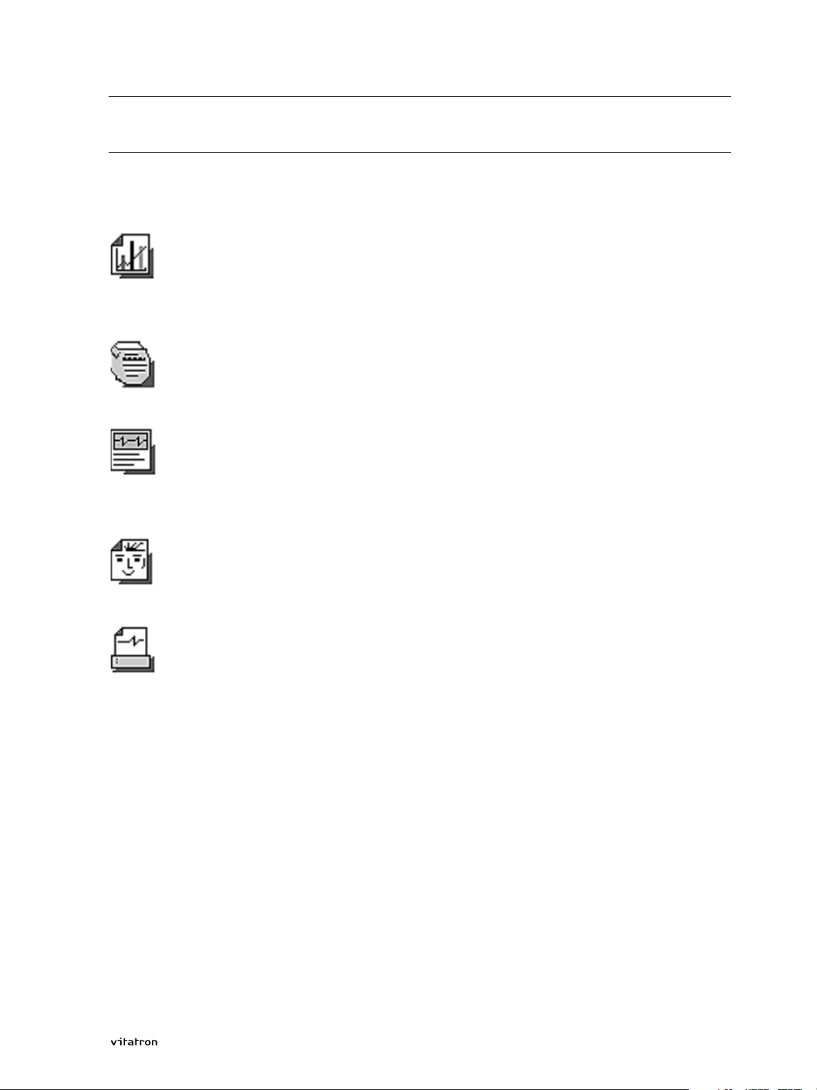
Control panel
In the control panel you will find icons that represent various
submenus: Data, Parameters, Tests, Patient, Reports.
Button line
General push buttons, such as Emergency and End Session,are
positioned in the button line at the bottom of the display.
8
Programming Guide
Page 11
2.3 Menu options
During tutorial sessions or follow-ups you can select certain menu
options. These are explained below.
Data
The Data menu enables you to retrieve the Status screen. Also, it provides Holter and Histogram selection and read-out options, as well as
data from the Counters function and Battery and Lead Measurements.
Parameters
The Parameters menu allows permanent or temporary programming of
parameters and functions.
Tests
In the Tests menu you can measure pacing thresholds, perform sens-
ing tests and VA or QT interval tests, initiate Fast Learn procedure,
start AOO Burst Pacing and turn ECG markers on or off, if applicable.
2.3 Menu options
Patient
The Patient menu is used to enter patient and pacing system data into
the pacemaker.
Reports
With Reports you can make a printout of various items, such as status
list and measurements. You can also save pacemaker data onto a
3.5 inch diskette.
Press the appropriate icon to access the desired menu.
9Programming Guide
Page 12
2.4 Vitatron tutorial
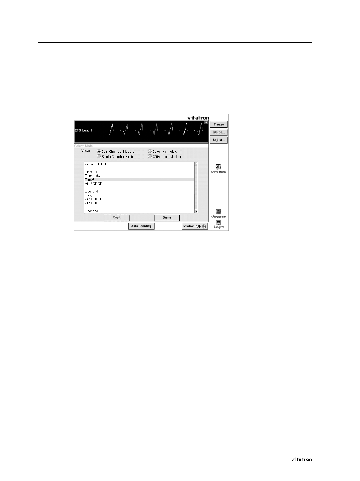
2.4 Vitatron desktop tutorial
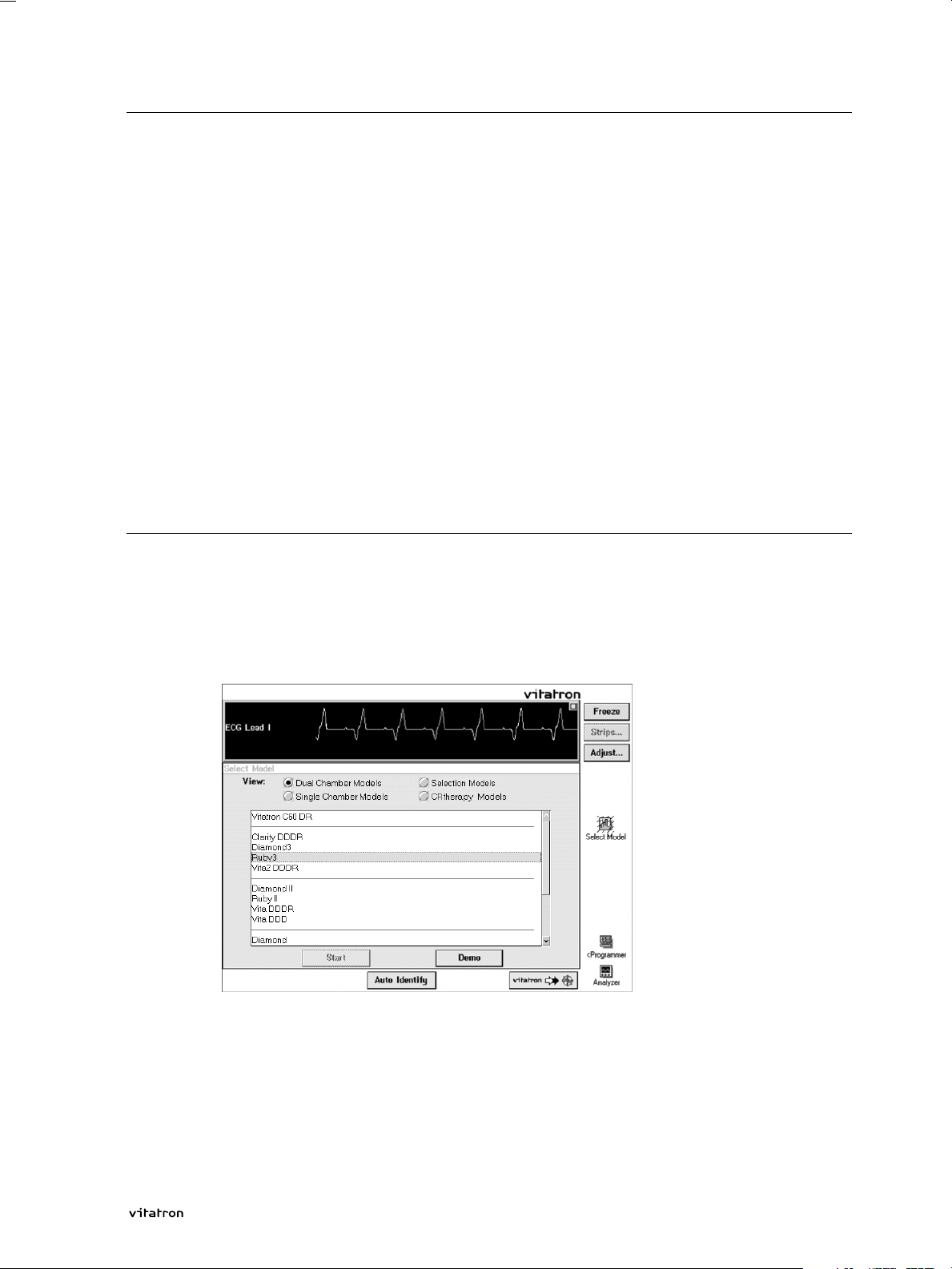
On completion of start-up, the Vitatron desktop is shown. From here
you can activate tutorial sessions that allow you to
familiarize yourself with programming procedures.
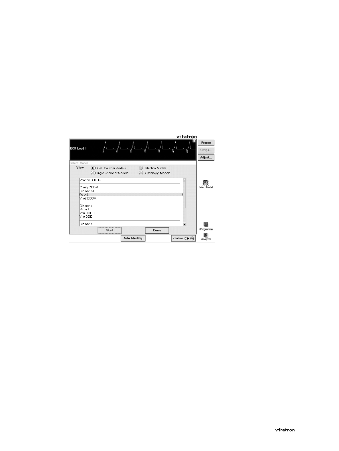
> To start a tutorial, select the desired model group from the list at the
top of the screen. Then select the desired pacemaker and press Demo
in the Vitatron desktop.
A Clarity DDDR tutorial is explained below.
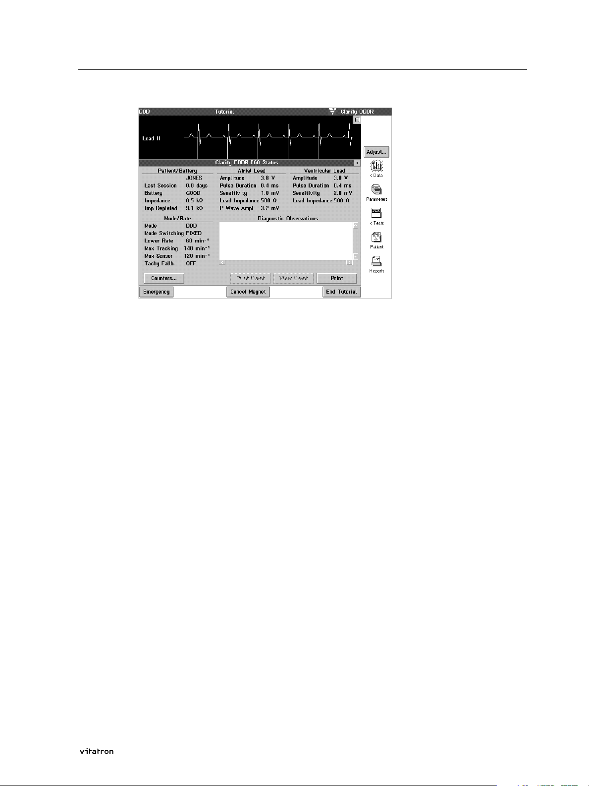
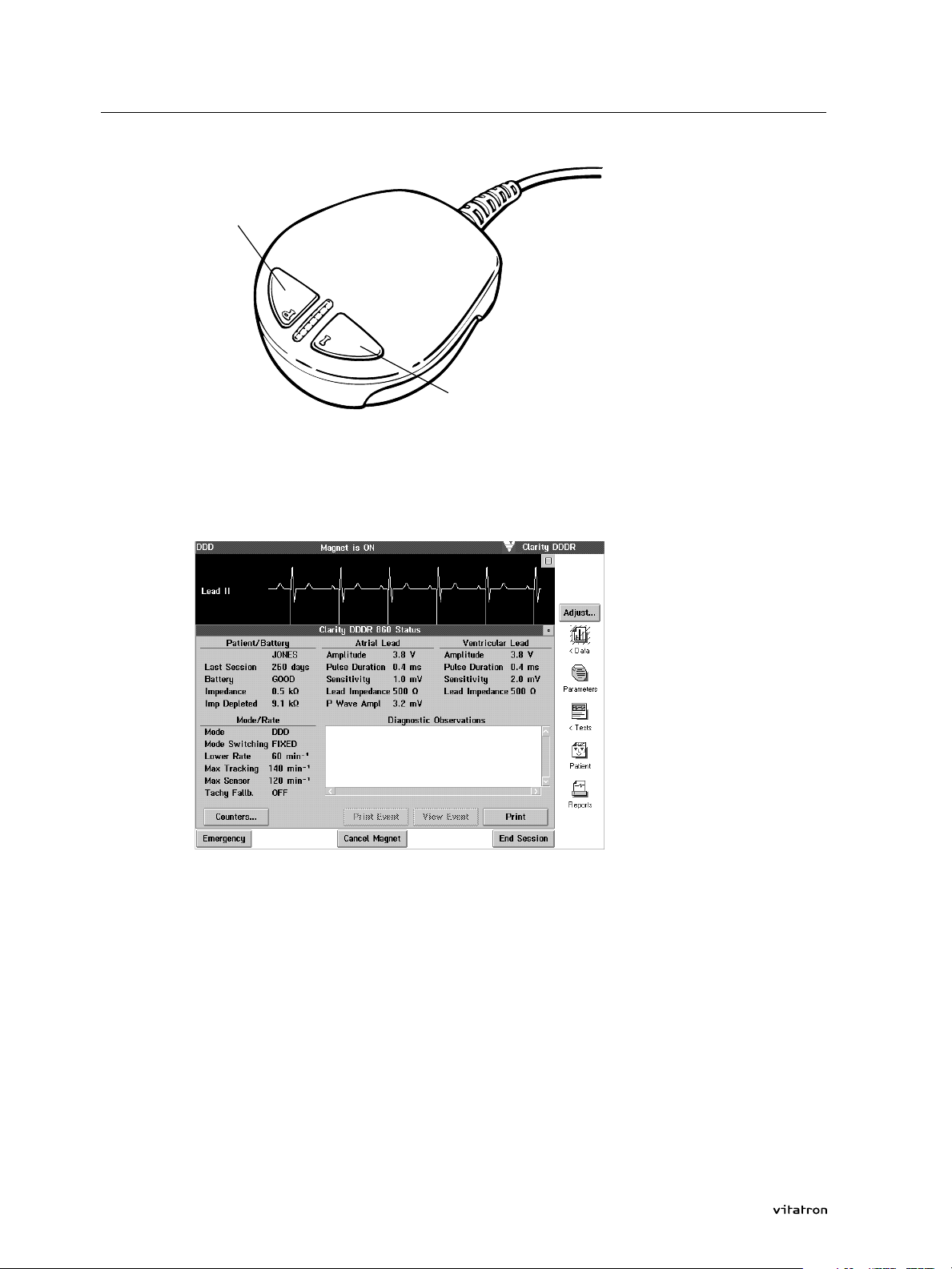
> Select Clarity DDDR and press the Demo button. The status screen is
displayed.
10
Programming Guide
Page 13
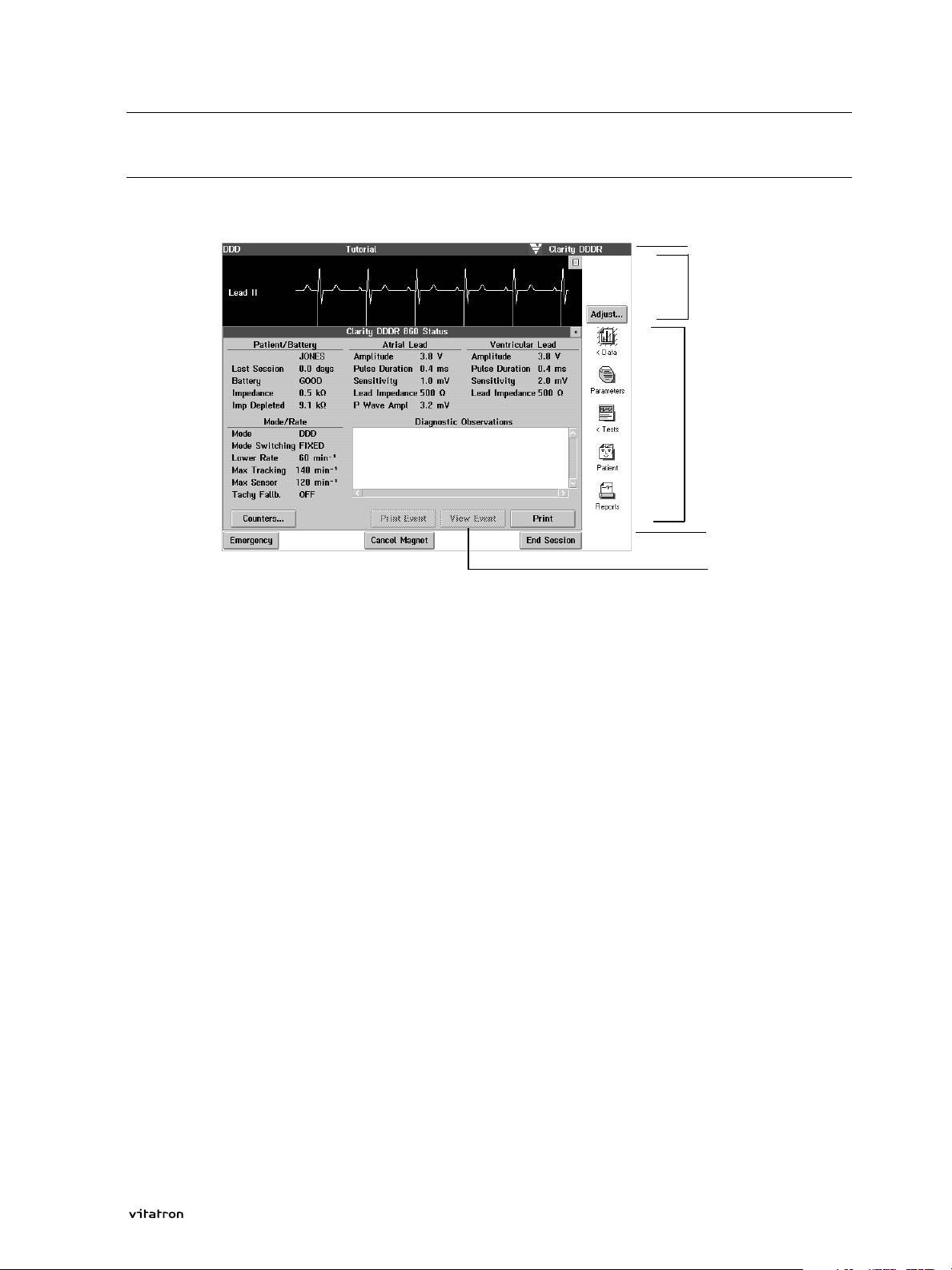
2.4 Vitatron tutorial
Note:
The Status screen appears at the start of a follow-up. It can be
recalled at a later stage of the programming session by pressing the
Data icon and selecting Status. See section 3.6.1.
The Status screen shows the main parameters and their programmed
values, measurement data, and results from counters if applicable. It
is not possible to change values in this screen. To leave this screen,
press the 'close' button (see below).
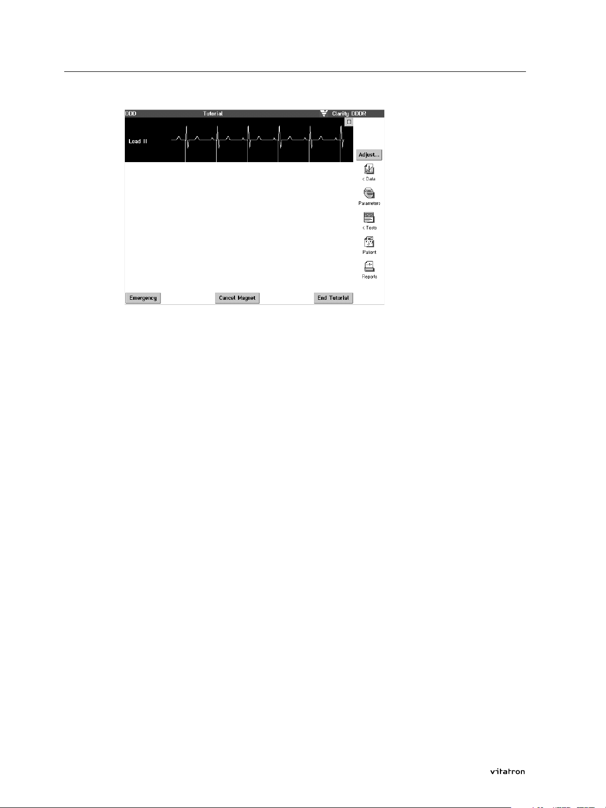
Close button
The top right corner of each menu contains a 'close' button. On pressing this button in the status screen, the window disappears and the
programmer displays the main menu screen shown below.
11Programming Guide
Page 14
2.4 Vitatron tutorial
Note:
To enter any other screen directly, without using the 'close' button,
you can select the appropriate icon while the programmer is still displaying the current menu screen.
This way of going from one screen to another directly is possible in all
menus. However, boxed values must first be programmed or
cancelled. The main menu screen shows several icons in the control
panel on the right, each representing a submenu with pacemaker programming and interrogation options.
During a follow-up, the Cancel Magnet/Activate Magnet button at the
bottom of the screen switches the magnet mode off or on respectively.
At the top of the screen you can check during the follow-up whether
the magnet is active or inactive (see section 3.17).
> Now press the Parameters icon to open the Parameters Therapy menu.
12 Programming Guide
Page 15
2.4 Vitatron tutorial
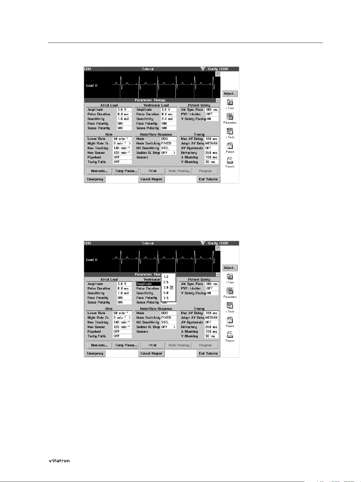
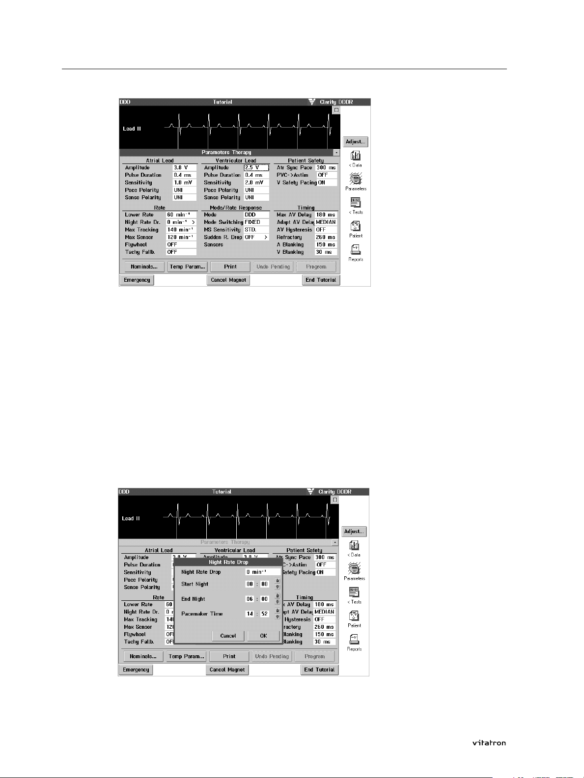
The programmer displays the programmed value of each parameter in
a highlighted box to its right.
> Press the value box for ventricular amplitude.
The currently programmed parameter value is indicated by means of
a boxed P to the right of that value.
> Select 2.5 V by pressing with the touch pen on the value 2.5.
The value selection window disappears and a dark border around the
value box indicates that the value is pending.
13Programming Guide
Page 16
2.4 Vitatron tutorial
Note:
If on opening the value selection window for a certain parameter you
decide not to select a new value, press outside the value selection
window to close it without changing anything.
Programming Night Rate Drop provides another example of a value
selection window appearing on the display. The > symbol at the right
of the value box indicates that on pressing this value box, a submenu
appears on the display.
> Press the Night Rate Drop value box.
14 Programming Guide
Page 17
2.4 Vitatron tutorial
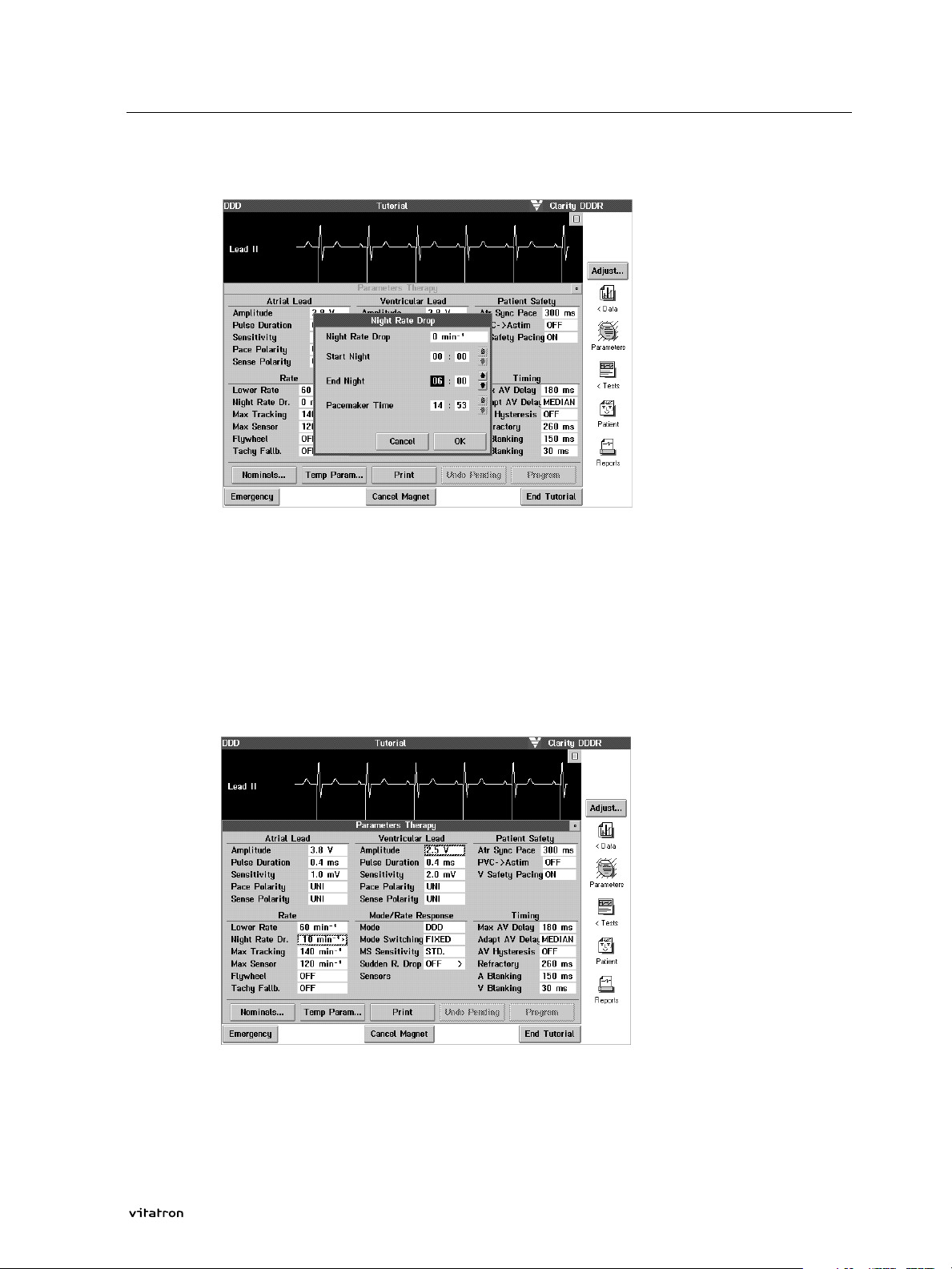
> Press the left End Night value box.
> Press the upward-pointing arrow displayed on the right of the End
Night time to select an End Night time of 7.00. Then press the Night
Rate Drop value box and press 10 in the list of options that is
subsequently displayed.
> Press the OK button to return to the Parameters Therapy screen.
Pressing Cancel takes you back to the Parameters Therapy screen without selecting new values.
Now both Night Rate Drop and Ventricular Amplitude have pending
values, as indicated by the dark border around the value box.
15Programming Guide
Page 18
2.4 Vitatron tutorial
> You can program the pending values by pressing the Program button
(you can return to the currently programmed settings by pressing the
Undo Pending button).
Upon pressing Program you will see the dark borders around the pend-
ing values disappear, which means they have been permanently programmed. Refer to section 3.13 for information on temporary
programming.
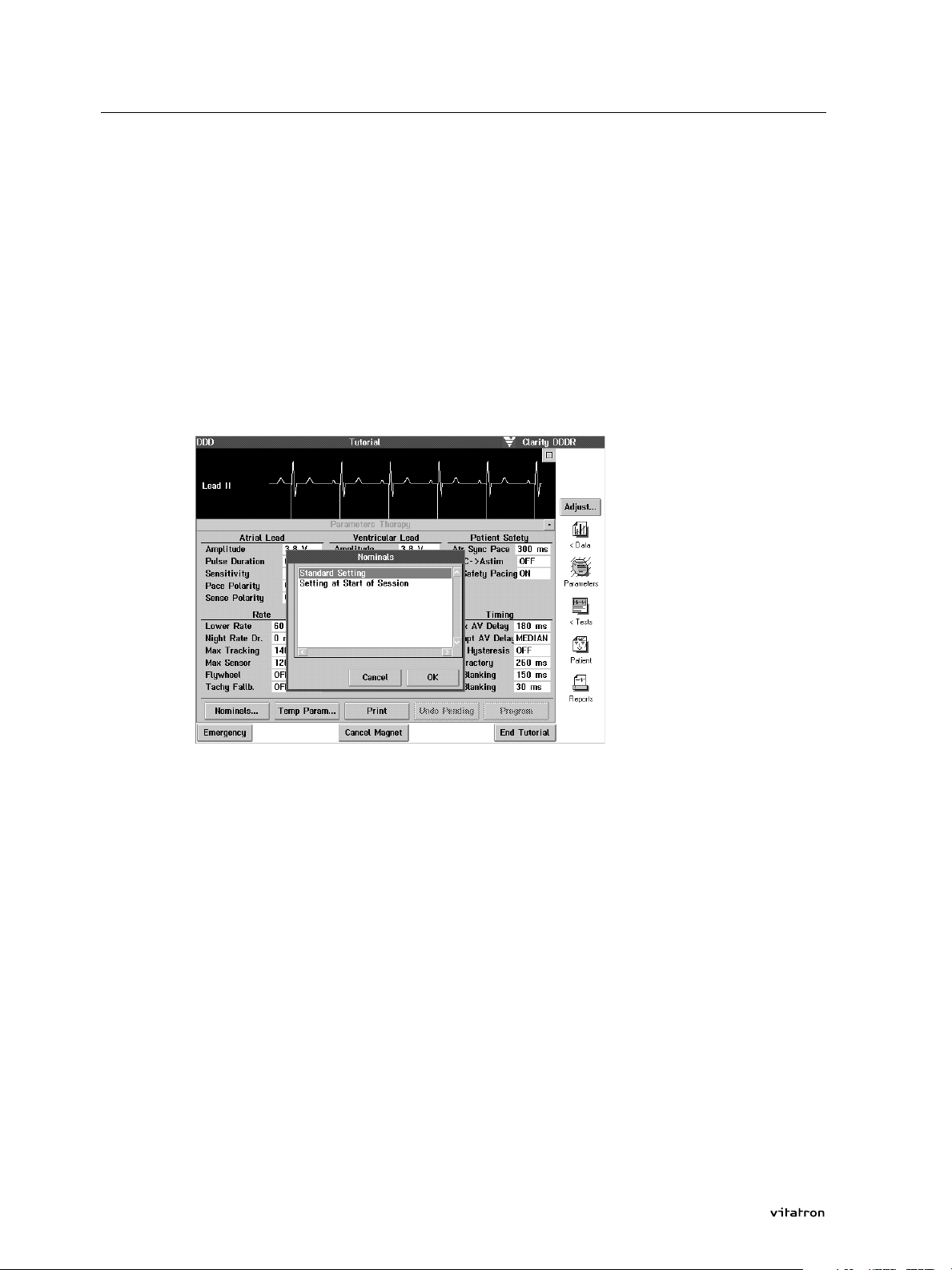
> To program the parameters to nominal values, press Nominals... first.
Selecting the first option, Standard Settings, programs the pacemaker
to the delivery settings defined by Vitatron and mentioned in the
applicable Product Information manual delivered with the pacemaker
concerned.
The second option, Setting at Start of Session, resets all parameters
changed so far to the values that were in effect at the start of this
tutorial.
> Press Setting at Start of Session, then OK. The programmer shows all
parameter values boxed indicating that they are pending. For permanent programming of these settings, press the Program button.
This completes programming the tutorial pacemaker back to its settings at the start of the session.
16 Programming Guide
Page 19
2.4 Vitatron tutorial
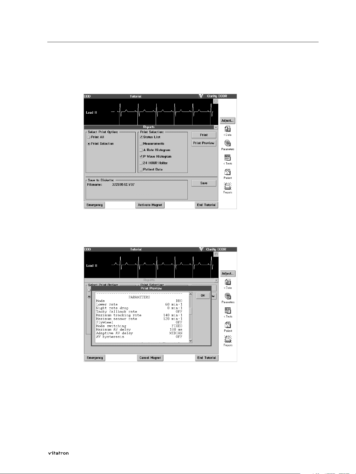
> Press the Reports icon.
> Press the selection box for Print Selection. A list from which you can
select items for printing now appears.
> Select Status list and Histogram by selecting the appropriate boxes.
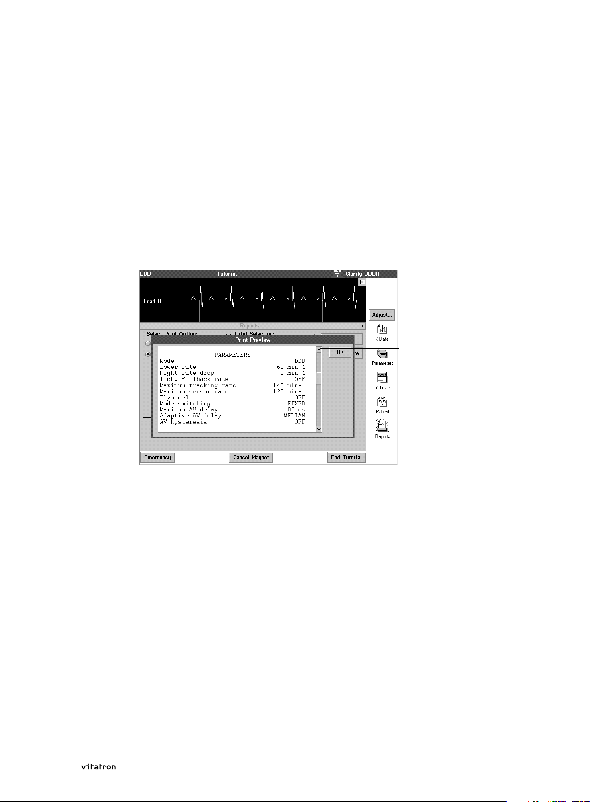
> Press Print Preview.
Pressing Print Preview will show what the printout is going to look like.
You can view text which does not fit on one window by scrolling
through it. See section 2.5 for an explanation of the scrolling
technique.
> Press OK to leave the Print Preview window.
17Programming Guide
Page 20
2.4 Vitatron tutorial
> Now press Print to obtain a printout of the selected items.
> Press the 'Close' button to leave the Reports menu.
> To end the tutorial session, press the End tutorial button. This takes
you back to the Vitatron desktop.
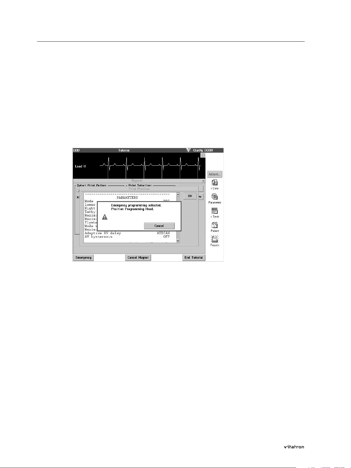
Emergency
> If you suddenly need to program emergency settings, press the Emer-
gency button on the bottom left of the display. This button is always
active after a pacemaker has been interrogated.
18
If the programming head is not applied to the pacemaker correctly
and the Emergency button is pressed, a message box appears. In a
patient follow-up, emergency operation starts as soon as the programming head is correctly positioned over the pacemaker and communication is established.
> In this example, the message disappears after pressing Cancel.
Emergency programming can also be performed by pressing the red
Emergency button left of the screen on the display panel. The
emergency procedure that is started by pressing this button is the
same as described for the on-screen emergency button.
More information on the Emergency procedure is presented in
Appendix 5.1.
Programming Guide
Page 21
2.5 Scrolling
Text displayed by the programmer, e.g. histogram or Holter information or a print preview, may be too long to fit in one window. In this
case, the programmer displays an activated scroll bar on the right of
it. This enables you to scroll through the text. See below for an example of how to use the scrolling technique.
> Press the Reports icon in the main menu, select Print Selection and
then Status List and press Print Preview.
2.5 Scrolling
Scroll button
Scroll box
Scroll shaft
Scroll button
Along the right side of the Print Preview window, a dark grey vertical
bar is displayed. This is called the scroll bar. It consists of four parts:
the scroll shaft, the scroll box and two scroll buttons. The scroll box
can move up and down through the scroll shaft. The scroll box
indicates the relative position of the information displayed in the
window. If the scroll box is positioned at the top of the scroll shaft,
the first part of the available information is shown. If the scroll box is
positioned at the bottom of the scroll shaft, the last part of the available information is shown.
Scroll bars may appear vertically, such as the one discussed above, or
horizontally. In a horizontal scroll box, you can retrieve all available
information by scrolling from left to right.
19Programming Guide
Page 22

2.5 Scrolling
1. Press scroll buttons
2. Press scroll shaft
There are 3 ways to move the scroll box.
Move the scroll box down through the scroll shaft by pressing the
lower scroll button once. Each time the scroll button is pressed, the
information displayed moves up one line.
Press the lower scroll button again to move up one more line. Repeat
this until all information has been displayed.
You may press the upper scroll button to bring information shown
earlier back into view.
Press inside the scroll shaft below or above the scroll box. This brings
the next or previous screen page into view.
3. Drag the scroll box
Drag the scroll box. Position the tip of the touch pen on the scroll box
and then move the pen in the desired direction without taking the
pen tip off the screen.
The information displayed in the window moves in and out of view
along with the scroll box. Press OK to leave the window.
20
Programming Guide
Page 23

3. Follow-up
3.1 Start-up and auto-identify
In this chapter you will find information on how to program and
interrogate a Vitatron pacemaker (see the beginning of this Programming Guide for the applicable models). A number of 'How to ...'
sections cover the most frequent programmer actions as performed
during a patient follow-up.
Figures provide examples of the programmer screen display during a
Clarity DDDR follow-up. These screens may look slightly different in
sessions with other pacemaker models but will have a similar structure.
21Programming Guide
Page 24
3.1 Start-up
3.1.1 Start-up
Turn the programmer on using the ON/OFF switch. The Vitatron logo
start-up screen appears briefly during start-up, provided Vitatron software has been installed and provided the last follow-up was carried
out on a Vitatron pacemaker.
On completion of start-up, the Vitatron desktop is displayed.
If the programmer shows a Medtronic screen layout at start-up, this
means that during the last patient follow-up a Medtronic implantable
pulse generator was programmed or interrogated. Press the Medtronic
to Vitatron switch to enter the Vitatron mode.
The model selection screen features various icons and buttons: Freeze,
Strips, Adjust, Select Model, Programmer, Analyzer(if installed) Start, Demo,
Auto-Identify, and the Vitatron to Medtronic switch. For a description of
the Select Model, Programmer and Analyzer functions see chapter 2.
For a description of the Freeze and Adjust functions see section 3.2.
22
Programming Guide
Page 25
3.1.2 Selecting Auto-Identify
> Press the Auto-Identify button to start the automatic pacemaker recog-
nition procedure.
Note that this procedure does not start unless Auto-Identify is pressed.
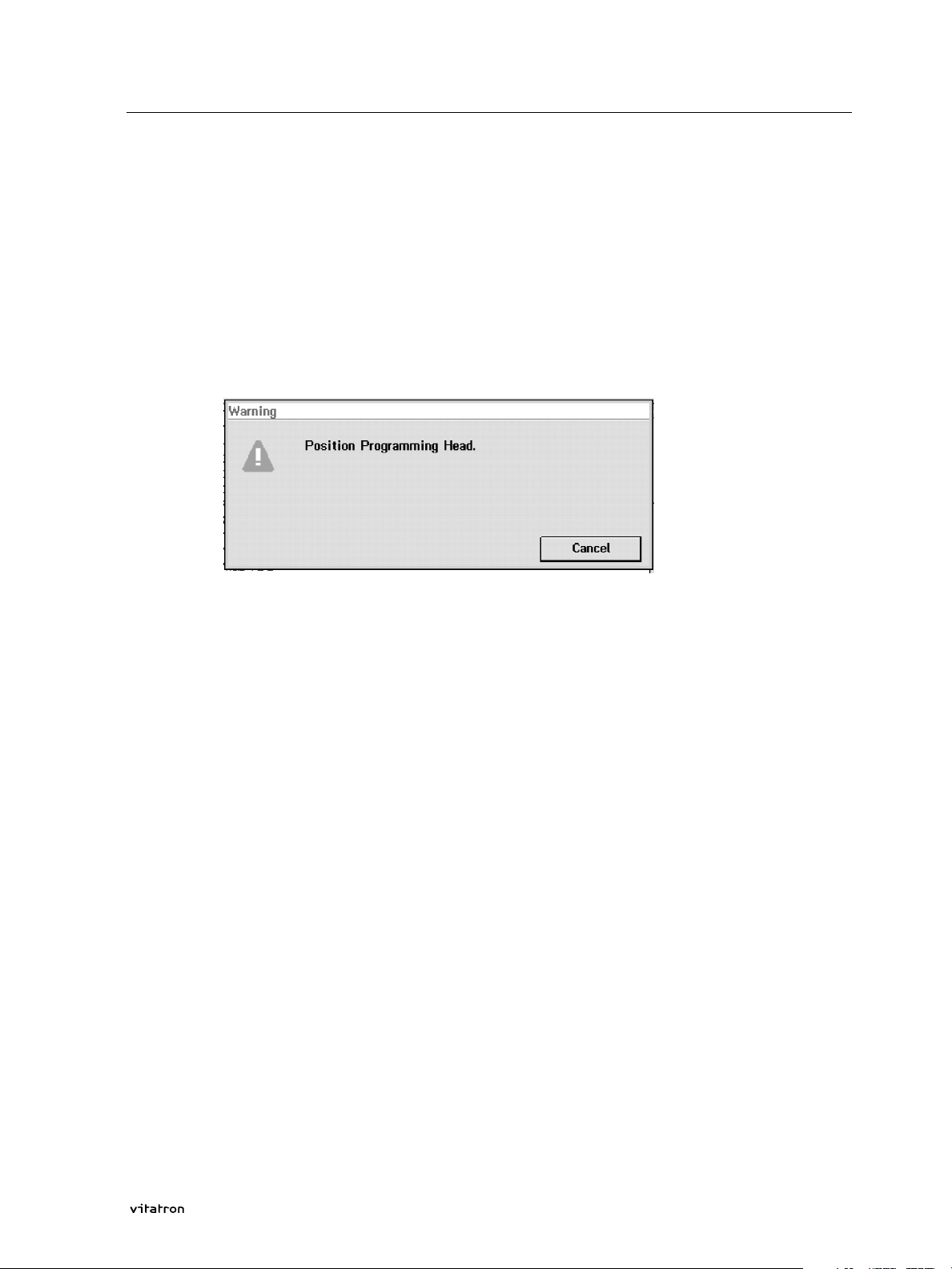
If the programming head is not positioned correctly the programmer
displays a warning message.
3.1 Start-up
> Position the programming head to continue the automatic model
selection procedure.
For information on correct positioning of the programming head,
see the programmer manual. On pressing Cancel the programmer
returns to the model selection screen.
Note:
The P (Program) button on the programming head serves as an alternative to the Program command that appears on the display screen.
The I (Interrogate) button on the programming head corresponds to
the Auto-Identify button on the screen. Both the Interrogate button
and the on-screen Auto-Identify button can be used to start the automatic pacemaker recognition procedure.
For convenience, you may press the Interrogate or Program button on
the programming head instead of selecting the corresponding option
from the display.
23Programming Guide
Page 26
3.1 Start-up
Program
Interrogate
Upon completion of the automatic pacemaker recognition procedure,
the programmer displays the status window showing the main
parameters of the recognized pacemaker. The pacemaker model is
displayed at the top of the screen.
24
Note:
You cannot program parameters in this window. Press the Parameters
icon to change parameter values and to select options. You may also
press one of the other icons to perform any of the related programmer
actions. Press the Print button to obtain a printout of the status
window.
Programming Guide
Page 27

3.1 Start-up
Auto identify unsuccessful
If the programmer recognizes the pacemaker as being a Vitatron
model, but cannot interrogate or program it a message to this effect
will appear. It could be that a software upgrade is needed. In such
cases it is always recommended that you contact your Vitatron representative
If the pacemaker is a Medtronic model, you must press the Vitatron to
Medtronic switch in the bottom right corner of the screen to enter
Medtronic applications.
If during a patient follow-up the programming head is applied to a
different pacemaker, the programmer will restart the automatic pacemaker recognition procedure.
25Programming Guide
Page 28

3.2 How to use the built-in ECG recorder
3.2 How to use the built-in ECG recorder
This section contains information on using the built-in ECG recorder.
For instructions on attaching the ECG cable and connecting the ECG
leads please refer to the programmer manual.
3.2.1 Using the ECG in the Vitatron desktop
When you switch the programmer on and the Vitatron desktop
appears the displayed ECG options and the ECG layout differ slightly
from those that are presented once a pacemaker has been
interrogated. Although the desktop options are not described extensively in this manual, the main difference is that in the Vitatron desktop it is possible to freeze and display the last 15 seconds of the
displayed ECG and subsequently analyze it using on-screen calipers.
The control buttons control the frozen ECG viewing window by letting
you move each of the two vertical cursors appearing in the window to
any desired position. The cursors thus act as calipers allowing you to
measure the time interval between events. The caliper measurement
is displayed in milliseconds in the upper-left corner of the window.
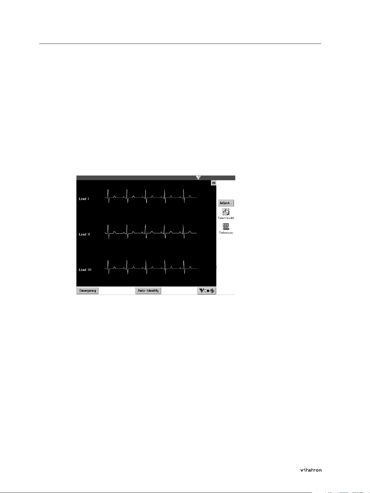
The ECG can be displayed in a minimised format, in which only one
lead is displayed in the ECG window at the top of the screen. It can
also be displayed in a full screen format, in which all three leads are
displayed simultaneously. In the top right corner of the ECG window, a
square push button is displayed to switch from one ECG format to the
other.
26
Programming Guide
Page 29
3.2 How to use the built-in ECG recorder
The ECG window is automatically opened in its minimized format
when the programmer is switched on.
3.2.2 Using the ECG during follow-up
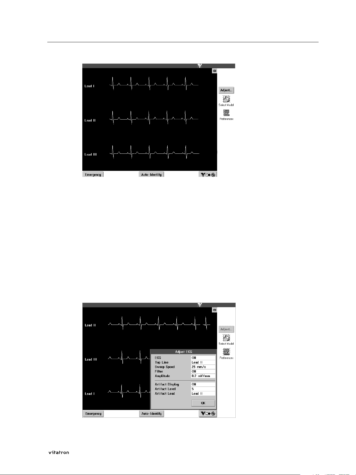
Once a pacemaker has been interrogated the ECG function can be
switched OFF and ON in the Adjust ECG menu.
> To open this menu, press the Adjust button on the right of the screen.
As long as the Adjust ECG window is opened, the ECG is displayed in
the full screen format.
27Programming Guide
Page 30
3.2 How to use the built-in ECG recorder
The Adjust ECG menu also includes the following parameters:
Top line, Sweep speed, Filter, Amplitude, Artifact Display, Artifact Level and
Artifact Lead.
Below is an explanation of how to adjust these settings:
Top line
You can select ECG lead I, II, or III. If the ECG is shown in the
minimized format, the selected lead is the only one displayed. If the
ECG is shown in the full screen format, the selected lead is displayed
on top, and the other two leads are displayed below.
28
Sweep speed
The Sweep speed option controls the sweep speed of the on-screen
ECG recorder, expressed in mm/s. Available values are 12.5, 25, 50, and
100 mm/s.
Filter
The Filter function controls the filtering of ECG signals by switching
between two different band widths.
Filter ON: bandwidth is 0.5 to 40 Hz
Filter OFF: bandwidth is 0.005 to 100 Hz
With the Filter switched on, clarity of the displayed and printed ECG
may be improved in the presence of interference.
Programming Guide
Page 31

3.2 How to use the built-in ECG recorder
> To adjust the Filter setting, open the appropriate value box by pressing
it with the touch pen.
> Press ON.
The value selection window closes, which indicates that your
selection has been accepted. Filter is now switched on. This change
takes effect immediately.
> Press OK to close the Adjust ECG window. The ECG is displayed in the
format it was in before adjusting.
The Filter setting can also be adjusted during ECG printing. The
adjustment takes effect immediately. In a similar way you can adjust
the other ECG settings described below.
Amplitude
The Amplitude option determines the size of all displayed ECG traces.
Available values range from 0.05 mV/mm to 1.0 mV/mm. The amplitude setting selected for the ECG signal applies to the printed ECG
trace as well.
Artifact Display
The programmer translates detected atrial or ventricular pacing
pulses into artifacts which are represented as vertical spikes in the
ECG window and on the ECG printout. These artifacts are also trans-
29Programming Guide
Page 32

3.2 How to use the built-in ECG recorder
ferred to the analog output for viewing on an external ECG monitor or
recorder.
The Artifact Display function can be turned ON or OFF. Below it is
explained how you can select an ECG lead for detection of pacing
pulses and how you can set the sensitivity level.
Artifact Level
This option controls the ECG system's sensitivity regarding the detection of pacing pulses. In order to prevent interference signals being
interpreted as pacing pulses or certain pacing pulses not being
detected, you should select the appropriate Artifact Level.
The available ranges for the Vitatron CareLink and 9790c are:
Vitatron CareLink - From 1 (very sensitive) to 5 (very insensitive).
9790c - From 1 (very sensitive) to 8 (very insensitive). Also available is
an 'auto' setting in which the programmer automatically varies its
Artifact Level between 5 and 8 to ensure optimal artifact display.
The required Artifact Level may vary due to the amount of
electromagnetic interference (EMI) present at the follow-up site.
30
Programming Guide
Page 33

3.2 How to use the built-in ECG recorder
Artifact Lead
This option determines which ECG lead is used to detect pacing
pulses. During programming or interrogation of the pacemaker, communication signals may appears as artifacts on the ECG. Turn Artifact
Display off or adjust Artifact level.
Print ECG
> To print the ECG by means of the built-in strip printer, press one of
the printer control buttons on the left of the programmer.
This will start printing of all three ECG traces at a speed of 12.5, 25 or
50 mm/s (the latter is only available in the Vitatron CareLink programmer).
The printing speed is indicated once, at the start of the printout.
During printing, a new printing speed can be selected. This change
takes effect immediately and is indicated on the printout by means of
vertical dashed line. The new printing speed is printed as well.
ECG Markers are only shown if this function is switched on
(see section 3.14).
> To stop printing, press the printer control button that represents the
selected printing speed, again.
31Programming Guide
Page 34

3.2 How to use the built-in ECG recorder
If the printer is out of paper, the programmer displays a message
saying so. Press Cancel to cancel printing or press OK after you have
installed printer paper to continue printing.
ECG calibration
The calibration button is positioned next to the analog output on the
right of the 9790c programmer and on the analog I/O box that is provided with the Vitatron CareLink programmer. Pressing the calibration
button initiates two calibration signals, one for the ECG leads and one
for the ECG Markers.
32
The calibration signal for the ECG leads consists of two pulses with an
amplitude of 1 and 5 mV respectively. The calibration signal for the
ECG Markers consists of 8 pulses referring to amplitude levels -4 to +4,
each representing a different amplitude. These calibration signals
appear on the printed and displayed ECG and Marker Channel and are
transferred to the external ECG recorder if connected. You may use the
signals to analyze the ECG and ECG Marker amplitudes by comparing
those to the height of the applicable calibration signal.
Warning:
This programmer is designed for monitoring purposes only. It is not
intended for independent diagnostic use. Only use the programmer with
surface electrodes.
Programming Guide
Page 35

3.2 How to use the built-in ECG recorder
Invalid ECG
If the ECG cannot be displayed on the screen fast enough, the data
displayed becomes invalid. The programmer will indicate this problem
with the following on-screen warning: 'ECG screen data has become
invalid. Press OK to restart proper ECG display.'
As long as this message appears on the programmer screen, ECG display is stopped and no new data is shown. Press OK to clear the current (invalid) ECG and start a new one.
33Programming Guide
Page 36

3.3 How to program a parameter
3.3 How to program a parameter
This section explains how a parameter can be programmed to a new
value. It deals with parameter programming, batch programming and
nominal programming.
3.3.1 Parameter programming
> Press the Parameters icon.
In the Parameters therapy screen, parameters can be selected for programming.
34
> To select a parameter, e.g. ventricular amplitude, press the parameter
value box, i.e. the highlighted window next to the parameter.
Programming Guide
Page 37

3.3 How to program a parameter
The currently programmed value, 3.8 V, is indicated by means of a
boxed 'P' to the right of that value.
> Select a new value, e.g. 2.5 V.
The ventricular amplitude value box now appears boxed to indicate
that 2.5 V is a pending value that can be programmed.
> To program the new parameter value, press the Program button in the
bottom right corner of the Parameters Therapy screen.
35Programming Guide
Page 38

3.3 How to program a parameter
Programming will start immediately provided the programming head
is applied to the pacemaker correctly. If this is not the case, the
programmer will display a warning asking you to reposition the programming head.
Programming can also be performed by pressing the P button on the
programming head.
Program
Interrogate
(Auto-Identity)
When the new parameter value has been programmed, the box
around the pending value disappears.
Pressing Undo Pending instead of Program returns the pending parame-
ters to their currently programmed values.
If you open a value selection window and you decide not to select a
new value, you can press outside the window to close it. Pressing a
different parameter value box also closes the one currently opened,
and opens the corresponding parameter selection window.
Some parameter value windows display a > character on the right,
indicating that pressing this window opens up a submenu with programmable parameters, e.g. the Night Rate Drop window.
3.3.2 Parameter pertinency
Only those parameter values that are applicable to the selected mode,
e.g. atrial amplitude in the AAIR mode, are shown on the programmer
display. This is called parameter pertinency.
36
Example
Suppose, with the pacemaker in the DDD mode, the atrial amplitude
Programming Guide
Page 39

3.3 How to program a parameter
is to be reprogrammed from 3.8 V to 2.5 V. The new value is boxed to
indicate that it is pending. If the mode is now changed to VVI, the
boxed atrial value of 2.5 V is cleared.
Pressing Program now results in permanent programming of both the
VVI mode and the pending value for atrial amplitude, 2.5 V. If the
pacemaker is subsequently reprogrammed to a dual chamber mode,
the atrial pulse amplitude will be 2.5 V. You can simulate this example
in a tutorial session. See section 1.5.
Warning:
If you select a new value for a certain parameter without yet programming
it, this pending value disappears from the programmer screen after selecting a new mode to which the parameter concerned is not pertinent.
However, it is still pending and will be permanently programmed after you
press the Program button. To prevent this situation, press Undo Pending
first, then select a new mode.
3.3.3 Batch programming
It is also possible to program several parameters (or features) in one
programming action.
> In order to perform batch programming, select a new value for each
parameter/feature that you wish to program, one after the other.
All changed (pending) parameter values appear boxed on the screen.
37Programming Guide
Page 40

3.3 How to program a parameter
> Now press Program to enter the new values into the pacemaker per-
manently. The boxed values are unboxed, which indicates the corresponding parameter has been changed.
Pressing Undo Pending instead of Program returns all pending parame-
ters to their currently programmed values.
3.3.4 Nominal programming
A special kind of batch programming is used to change all parameters, if applicable, to nominal settings. Nominal settings can be either
the settings at the start of the session or the standard settings defined
by Vitatron.
> For nominal programming, press the Nominals button on the bottom
left of the Parameters Therapy screen. Then choose between 'Standard
Setting' and 'Setting at Start of Session' and press OK.
All parameters are boxed showing new values if applicable.
> Now press Program to change all parameters to nominal settings.
The pending values are now unboxed, indicating they have either
been successfully programmed into the pacemaker. Pressing Undo
Pending returns all pending parameters to their currently programmed
values.
38
Programming Guide
Page 41

3.3 How to program a parameter
Note:
If one or more parameters are still pending and you either press the
'close' button in the top right corner of the screen or try to open
another screen, a warning appears asking you to either program or
cancel the pending values. Press OK to continue.
Warning:
Pacemaker programming should be done only after careful study of the
Product Information manual enclosed with the pacemaker and determination of the appropriate parameter settings. Improper use of the programmer could result in erroneous or inadvertent programming and improper
operation of the telemetry and measurement functions.
Warning:
If power to the programmer is unexpectedly lost, lifting the programming
head away from the patient's pacemaker cancels any temporary parameters or functions in effect and restores the pacemaker to its permanently
programmed state. Loss of power during permanent programming of one
parameter cancels the programming action. After the programmer is
turned back on and the appropriate application is started, the
programming action must be started again.
Warning:
If power is lost during permanent programming of batched parameters, all
parameters that had already been reprogrammed before the power loss
keep their new value. All other parameters, including the one being repro-
39Programming Guide
Page 42

3.3 How to program a parameter
grammed at the moment that power is lost, keep the values they had
before the batch programming action was started. After the programmer is
turned back on and the appropriate application is started, the
programming action must be performed again for those remaining parameters.
If power is lost during a follow-up, the nominal values of Setting at Start of
Session are lost too. After restarting the programmer, the data obtained
through the initial interrogation procedure constitutes the new nominal
values of Setting at Start of Session.
40
Programming Guide
Page 43

3.3.5 Additional programming for the Selection AFm 902
How to program Ventricular Rate Stabilization
Press the Parameters icon in the Main Menu screen to open the
Parameters Therapy screen.
3.3 How to program a parameter
Ventricular Rate Stabilization (V. Rate Stabil.) and the parameters
maximum AFtherapy rate (Max Therapy) and AF deceleration are
listed under the heading 'AF Therapy'. They can be programmed by
pressing the appropriate value box in the Parameters Therapy screen.
Notes:
1. In the event of a power failure or interruption while parameter
programming is in progress, Ventricular Rate Stabilization will be programmed OFF.
2. If the mode is changed from DDD(R) or VVI(R) to any other mode
while Ventricular Rate Stabilization is ON, Ventricular Rate
Stabilization will be programmed OFF.
41Programming Guide
Page 44

3.4 How to measure pacing thresholds
3.4 How to measure pacing thresholds
> To perform an atrial or ventricular pacing threshold measurement,
press the Tests icon in the main menu screen.
> Select the Pacing Threshold option.
> Select one of the options shown on the left, e.g. A Amplitude and then
press the touch pen on Press and Hold and keep it pressed there to perform the measurement.
42
Programming Guide
Page 45

3.4 How to measure pacing thresholds
The programming head must be applied to the pacemaker correctly
and continuously. Note that measurements can be performed
independent of the programmed mode. In a dual chamber model for
instance, you can measure the pacing threshold for atrial amplitude
while the pacemaker is programmed to a ventricular mode.
> Watch the ECG carefully, either on the programmer display or an ex-
ternal ECG monitor. On loss of capture, release the Press and Hold
button to stop measuring.
The pacemaker returns to its permanently programmed settings.
Unless you release the Press and Hold button or remove the programming head, the programmer will continue to pace at decreasing atrial
amplitudes in a step-down cycle until it reaches the minimum value.
On completion of the measurement, the pacemaker returns to its programmed settings.
The threshold value is displayed under Results in the middle of the
screen. At the bottom of the screen, in the Parameter Setting window,
you can program the pacemaker to a new atrial amplitude duration
based on the outcome of the test as you consider appropriate. Also,
you can program new values for parameters such as atrial pulse duration or atrial pace polarity to perform the test again. See section 3.3
for general information on the programming of parameters.
If the Parameter Setting window contains boxed parameters, measuring pacing thresholds is not possible. Press Program or Undo Pending
first, then start the measurement.
In the same way, you can perform a threshold test for ventricular
amplitude, and atrial or ventricular pulse duration, if applicable. These
parameters can also be programmed to a new value in the Parameter
Setting window.
Print and Print Preview
Between measurements, you can press the Print Preview button to
retrieve the measurement list. This list can be printed by touching the
Print button.
43Programming Guide
Page 46

3.4 How to measure pacing thresholds
See section 3.10 for further information on Print and Print Preview.
Note:
For the sake of pacing threshold measurements, you may have
programmed new values for atrial or ventricular amplitude or pulse
duration in the Parameter Setting window. Note that these are permanent parameter values. Determine whether they are appropriate for
the patient. If necessary, program new values that provide an
adequate safety margin.
> You can leave the Pacing Threshold window by pressing the 'close'
button in the top right corner or by clicking one of the other icons in
the control panel on the right, which subsequently opens the
corresponding menu.
44
Programming Guide
Page 47

3.5 How to perform a sensing test
> To measure amplitudes, press the Tests icon in the main menu screen.
3.5 How to perform a sensing test
From the options displayed, select Sensing Test.
> Select one of the options displayed on the left, e.g. P-Wave Amplitude,
by pressing the appropriate selection box.
> Press Start to begin the sensing test.
The programming head must be applied to the pacemaker correctly
and continuously.
45Programming Guide
Page 48

3.5 How to perform a sensing test
Note that measurements can be performed independent of the
programmed mode. In a dual chamber model for instance, you can
test P-wave amplitude while the pacemaker is programmed to a ventricular mode. However, you can not change the atrial sensitivity and
atrial polarity during the test.
> Prior to and during the test, you can adjust the pacing rate. Press the
rate value box and then press the appropriate up or down arrow.
For R-wave amplitude measurements the AV delay can also be
adjusted prior to, but not during the test. Alternatively, the pacemaker
can be temporarily reprogrammed to the VVI mode.
On completion of the test, the measured amplitude is displayed under
Results. In the Permanent Setting window at the bottom of the screen,
you can program atrial or ventricular sensitivity to new values that
you consider appropriate on the basis of the test results.
To stop the test before it is completed, press Stop. After the test is
stopped, the temporary rate at which the test was performed remains
visible. However, the pacemaker resumes normal operation at the programmed rate on completion of the test.
Note:
If the Permanent Setting window contains boxed values, measuring
amplitudes is not possible. Press Program or Undo Pending first, then
press Start to begin the test.
Print and Print Preview
Between measurements, you can press the Print Preview button to
retrieve the measurement list. This list can be printed by pressing the
Print button. See section 3.10 for further information.
Note:
For the sake of the sensing test, you may have programmed new sensitivity in the Parameter Setting window. Note that these are permanent parameter values. Determine whether they are appropriate for
the patient. If necessary, program new values that provide an
adequate safety margin.
46
Programming Guide
Page 49

3.5 How to perform a sensing test
> You can leave the Sensing Test window by pressing the 'close' button
in the top right corner or by clicking one of the other icons in the control panel on the right, which subsequently opens the corresponding
menu.
47Programming Guide
Page 50

3.6 How to retrieve data
3.6 How to retrieve data
During interrogation of a pacemaker all counters, histograms and
Holters can be read out. The contents of the counters and histograms
are then cleared and the information is subsequently retained in the
programmer memory until the programming session is ended.
If you want to save information from histograms and counters it must
be printed out before ending the programming session. The information will otherwise be lost.
> Press the Data icon to gain access to the status screen and to other
data, which may include Histograms, Holters, Mode Switching Trend,
Selected Events, Set Diagnostics, Counters and Battery and Lead
Measurements. An [i] following the listed feature indicates that it has
already been read out during initial interrogation of the pacemaker.
48
Programming Guide
Page 51

3.6.1 Status and diagnostic observations
> Select status to open the status screen.
3.6 How to retrieve data
This screen shows the main parameters and their programmed
values. It is not possible to change values here. To change a value or
option, press the Parameters icon in the control panel on the right (see
section 3.3.1).
> Press the Print button to obtain a printout of the status list.
The status screen also contains a Diagnostic Observations window.
This function is only active if the implantation date has been entered
(see section 3.12).
> Select a message in the Diagnostic Observations window and press
'View Event'. The selected message is explained and suggestions are
given on how you may optimize settings.
49Programming Guide
Page 52

3.6 How to retrieve data
Warning:
'Diagnostic observations' can never replace expert judgement.
Notes:
1. To print the information shown on the screen return to the status
screen and press 'Print Event'.
2. Press the 'close' button to return to the status screen.
The Counters button in the bottom left corner enables you to retrieve
the results from Counters (see section 3.8.).
3.6.2 Histograms
> To retrieve histograms, press the Data icon on the right of the screen.
A list of options is displayed, including the active histogram(s). In
Clarity DDDR pacemakers, for example, the P-wave amplitude
histogram and the atrial rate histogram are always active in atrial sensing modes.
At the start of each session, all fixed histogram information collected
since the last follow-up is automatically transmitted to the programmer during interrogation of the pacemaker. To retrieve it press the
applicable option in the Data window
50
Programming Guide
Page 53

> Select the P-wave amplitude histogram.
The programmer warns you if no information is available.
3.6 How to retrieve data
> Press the Print button to print the information shown on the screen.
Press the 'close' button in the top right corner to leave the P-wave
amplitude histogram window.
In addition to the fixed histograms, one extra histogram can be
programmed. For instructions on how to program a certain histogram,
see 3.7.1.
The pacemaker will have gathered data for the programmed
histogram type since the last follow-up or since the histogram was
last programmed.
> The histogram data can be displayed by pressing the applicable option
in the Data submenu.
51Programming Guide
Page 54

3.6 How to retrieve data
The programmer warns you if no information is available.
> Press the Print button to print the information shown on the screen. If
the histogram has been reprogrammed and you want to read the histogram data, press Read. Press the 'close' button in the top right corner
to leave the Histogram window.
During follow-up, a new type of histogram can be programmed. This
new histogram will be listed in the Data submenu. If you had already
retrieved the data for the previously programmed histogram from the
pacemaker, this histogram will remain listed as an available option in
the Data submenu. It is marked with [i] meaning that the data for that
Histogram has been interrogated.The new programmed histogram type
is listed without a symbol.
However, if you are going to view data for the new histogram on the
screen, note that all data gathered for the previously programmed histogram is deleted. The programmer displays a warning in this case.
First, press Print in the applicable histogram window to obtain a printout of all data gathered for the previously programmed histogram.
Then press Read in the applicable Histogram window to retrieve data
on the new type of histogram from the pacemaker.
Press the Print button to obtain a printout of the data. Press the 'close'
button in the top right corner to leave the Histogram window.
52
Programming Guide
Page 55

If you open the Data submenu now, you will notice that the newly
programmed histogram is marked with [i] meaning this is the interrogated histogram now present in the programmer memory. The previously programmed histogram type has disappeared from the list.
3.6.3 Holters
At the start of each session, all Holter information collected since the
last follow-up is automatically transmitted to the programmer during
interrogation of the pacemaker.
> To retrieve Holter information, press the Data icon in the main screen.
From the list of options, select the programmed Holter. The Holter
information is now retrieved and displayed.
3.6 How to retrieve data
The programmer warns you if no information is available.
> Press Read to retrieve data for the programmed Holter. Press the Print
button to obtain a printout. Press the 'close' button in the top right
corner to leave the Holter window.
53Programming Guide
Page 56

3.6 How to retrieve data
During the session, a new type of Holter can be programmed. This
new Holter will be listed in the Data submenu. If you had already
retrieved the data for the previously programmed Holter from the
pacemaker, this Holter remains listed in the Data submenu. It is
marked [i], which means that the data has been retrieved from the
pacemaker. The newly programmed Holter is listed without a symbol.
However, if you are going to view data from the new Holter on the
screen, Note that all data gathered for the previously programmed
Holter type will be deleted. The programmer displays a warning in
this case.
Press Print in the applicable Holter window first to print out the data
gathered for the previously programmed Holter. Then press Read in
the applicable Holter window to retrieve data on the new type of
Holter from the pacemaker. Press the Print button to obtain all data on
a paper printout. Press the 'close' button in the top right corner to
leave the Holter window.
If you open the Data submenu now, you will notice that the newly
programmed Holter is marked with [i], which means that this is the
interrogated Holter now present in the programmer memory. The previously programmed Holter has disappeared from the list.
3.6.4 Mode Switching Trend
> To retrieve information on the Mode Switching Trend, select this
option from the Data submenu (see section 3.6). The display shows
you a diary (cause, duration and date) of long mode switches, number
of short mode switches and percentage 'fast resynchronization'.
A vertical scroll bar allows you to scroll through the diary.
Press Read to update the information on selected events (events that
may have occurred since the start of follow-up). Press Print to obtain a
printout.
54
Programming Guide
Page 57

3.6.5 Selected Event Recording
> To view Selected Events, select this option from the Data submenu
(see section 3.6). The display shows a 'Diary' containing the storage
period and number of episodes of the selected events.
3.6 How to retrieve data
Press View Report to preview the selected episode (rate profile diagram
or marker ECG diagram). A scroll bar allows you to scroll through the
selected episode.
55Programming Guide
Page 58

3.6 How to retrieve data
Press Read to add information that may have been collected since the
pacemaker was last interrogated. Press Print Report to obtain a printout.
All collected events can be removed from the pacemaker and programmer memory by pressing the 'Clear Events' button. Use the
'close' button in the top right-hand corner to leave the window.
Note:
The markers used for marker ECG are the same as those used for the
ECG event markers (see 3.14).
56
Programming Guide
Page 59

3.7 How to set Diagnostic Features
> To set Diagnostic Features press the Data icon in the main menu and
then select 'Set Diagnostics'. A submenu showing the current settings
for Histograms, Holters, Mode Switching Trend and Selected Event
Recording is now shown.
3.7 How to set Diagnostic Features
3.7.1 Histograms or Holters
> To activate a certain histogram, e.g. 'PVC vs Time of Day', press the
relevant value box.
57Programming Guide
Page 60

3.7 How to set Diagnostic Features
> Select 'PVC vs Time of Day' with the touch pen.
The histogram value box is now boxed to indicate a new pending
value.
> Press Program to activate this histogram in the pacemaker.
You can program a new Holter by following the same procedure.
3.7.2 Mode Switching Trend
> To activate the Mode Switching Trend, press the relevant value box.
58
Programming Guide
Page 61

> Select the desired setting and press Program to send the instruction to
the pacemaker.
3.7.3 Selected Events
> To set Selected Events, press the relevant value box.
3.7 How to set Diagnostic Features
Select the desired settings and press OK. Then press Program to send
the instruction to the pacemaker.
3.7.4 Additional Diagnostics for the Selection AFm 902
How to program diagnostic parameters
To program additional diagnostic parameters for the Selection AFm
902, press the Data icon in the main menu screen first. The Data submenu is displayed.
59Programming Guide
Page 62

3.7 How to set Diagnostic Features
Next, select Set Diagnostics from the Data submenu. This opens the
Set Diagnostics menu. In this menu you can program histogram and
Holter types, and atrial arrhythmia recording parameters.
How to program atrial arrhythmia recording parameters
Pressing the arrhythmia recording value box in the Set Diagnostics
menu will open the atrial arrhythmia recording menu. In this menu
the programmable parameters are listed.
60
Programming Guide
Page 63

3.7 How to set Diagnostic Features
To program a parameter, for instance the detailed onset reports, press
its value box and select the preferred setting. You can choose the total
number of detailed onset reports that will be stored (horizontal axis),
and how they will be divided into 'first' and 'last' reports (vertical
axis). For example, selecting '2+6' means that a maximum number of
8 detailed onset reports will be stored, divided into the first 2 and the
last 6.
After having selected the preferred setting, the atrial arrhythmia
recording menu is revealed again. Select the other parameters in a
similar way.
When all atrial arrhythmia recording parameters have the preferred
settings, click on OK. Now the Set Diagnostics menu reappears. Press
Program if you want to program the new settings. Select Undo Pending
to keep the currently programmed settings.
61Programming Guide
Page 64

3.7 How to set Diagnostic Features
How to retrieve atrial arrhythmia recording data
To retrieve the atrial arrhythmia recording data select this option in
the Data submenu. This starts the interrogation of the atrial arrhythmia recording data from the pacemaker. When the interrogation is
completed, the data is displayed on the screen.
62
If the atrial arrhythmia recording data has been interrogated during
the same session already, this is indicated with the symbol [i]. In that
case, selecting arrhythmia recording in the Data submenu displays the
data retrieved.
Programming Guide
Page 65

3.7 How to set Diagnostic Features
The atrial arrhythmia recording data screen consists of three parts:
1. A Summary section listing the main atrial arrhythmia counter data.
2. A Reports section with print and print preview options. Check the
appropriate box if you want to include its data in the printout of the
Reports section.
3. A Detailed Onset Reports section, also with print and print preview
options. The message 'No detailed onset reports available' appears when
no arrhythmia episodes have been recorded.
Press Read All to:
- interrogate all atrial arrhythmia recording data including
histograms, counters, arrhythmia diary, and detailed onset reports at
once. This is also useful in case you want to save these data on a
diskette. Note that the interrogation may take a while;
- update diagnostic data that was interrogated already. This will also
load all available detailed onset reports into the programmer's
memory.
Press Clear All to clear all atrial arrhythmia recording data. The interrogated data will remain available.
Note:
The Read All and Clear All buttons apply to all atrial arrhythmia
recording data. Upon pressing either of these buttons, a warning is
displayed, and you are asked to cancel or confirm your choice.
Counters, Histograms and Arrhythmia Diary
You can view the data stored in the counters, histograms and/or
arrhythmia diary of the Reports section by checking the appropriate
boxes and pressing Print Preview. The Print Preview window contains
the data of the selected items, which you can view by scrolling
through it from top to bottom.
Press Print to obtain a printout of the selected items in the Reports
section.
63Programming Guide
Page 66

3.7 How to set Diagnostic Features
Detailed Onset Report
Select a detailed onset report of which you want to see more data. The
dashed line indicates the separation between 'first' and 'last' recorded
detailed onset reports.
Press Print or Print Preview to start interrogation of the pacemaker.
When the interrogation has been completed, the report concerned is
marked with the symbol [i].
Pressing Print Preview opens the selected detailed onset report
window.
The detailed onset report window consists of three sections that you
can view on the screen by scrolling from left to right:
1. Episode information and the rate and PAC trend.
2. The rate profile diagram.
3. The marker ECG diagram.
Press the Print button to print the selected detailed onset report.
Note:
Make sure that the paper supply is sufficient before printing the
detailed onset reports.
64
Programming Guide
Page 67

3.7 How to set Diagnostic Features
Warning:
All atrial arrhythmia recording data is lost if:
• the pacemaker is reprogrammed to another mode;
• the pacemaker is programmed to standard settings;
• the battery status is 'depleted';
• atrial arrhythmia recording is turned OFF;
• any of the atrial arrhythmia recording parameters is
reprogrammed;
• the Clear All button is pressed and data clearing is confirmed with OK.
All atrial arrhythmia recording data stored in the pacemaker is lost if any of
the above mentioned situations occur. However, all interrogated data will
still be available until the follow-up is ended, or the Read All button is
pressed. In all cases the programmer will display a warning before any
data is cleared.
65Programming Guide
Page 68

3.8 Results from counters
3.8 Results from Counters
> To retrieve results from Counters, press the Data icon in the main
menu screen and then select Counters.
This window displays information collected by the various counters
and read out during interrogation of the pacemaker. The counters are
divided into three groups, i.e. Events, Atrial Rates and Diagnostic Data.
This information provides you with additional patient evaluation
tools.
66
Programming Guide
Page 69

3.9 Battery and lead data
> In order to retrieve data on battery and lead performance, press the
Data icon in the main menu screen and then select Battery & Lead
Measurement.
3.9 Battery and lead data
In the Battery & Lead Measurement window the programmer lists all
available data on atrial and ventricular output, if applicable. In addition, the battery status and lead impedance are given in the bottom
left corner.
Battery and lead data are obtained during initial interrogation of the
pacemaker, which takes place automatically at the start of a follow-up
after completion of the automatic pacemaker recognition procedure.
> To repeat the lead measurement, press the Measure button in the top
right corner of the Battery and Lead Measurement window.
67Programming Guide
Page 70

3.10 How to print pacemaker data
3.10 How to print pacemaker data
The programmer features a built-in strip printer and can also
support an external full size printer. You can select the printer in the
Programmer menu (see section 5.2.1). You can print various items,
including Status list, Measurements and Holter/histogram data.
You can print all available items, or only items you have selected
yourself. In addition, you can print a Pacer Memory Copy in the case
of programming difficulties, if the pacemaker behavior cannot be
interpreted, or if a pacemaker malfunction is suspected. This enables
Vitatron specialists to evaluate the pacemaker status and assist you in
the next patient follow-up.
> To print data, press the Reports icon in the main menu.
> In the Reports menu you can select Print Options by checking the ap-
propriate box.
68
After pressing the selection box for Print Selection, a list from which
you can select items for printing appears.
> Select the desired items by checking the appropriate boxes.
Programming Guide
Page 71

3.10 How to print pacemaker data
Print Preview
> Select Print Preview to view all data selected for printing.
They are shown in the same format as they will be printed on paper
after selecting Print.
Use the scroll box to view data that do not fit in one Print Preview
window. See section 2.5 for an explanation of the scrolling technique.
> Press OK to leave the Print Preview window.
Print
> To start printing, press the Print button on the right.
If the printer runs out of paper while processing a print job, it may not
resume printing after you have replaced printer paper. In this case,
initiate the same print job again to obtain a complete printout.
Note:
Printing of specific menu-related data can be done from within the
applicable menu. For example, a measurements list can be printed by
selecting Print in the Pacing Threshold menu.
69Programming Guide
Page 72

3.11 How to save pacemaker data to diskette
3.11 How to save pacemaker data to diskette
To save follow-up data to a DOS-formatted diskette, first press the
Reports icon in the Main Menu screen. Next, press the Save button in
the Reports screen to save the data on the inserted diskette. The programmer automatically generates a file name with the date and time.
The saved file contains all data that has been interrogated during that
session (programmed parameters, results of measurements, diagnostic data, patient information, etc.). Check the Data Submenu to determine which histograms and Holters have been interrogated.
Data saved on diskette from the Selection AFm 902 can be accessed
using the Vitatron AFdiscover user software.
Warning:
Make sure only virus-free diskettes are used!
Warning:
Remove the diskette from the disk drive before you turn the programmer
OFF after the follow-up session(s). Do not switch the programmer ON
when a diskette is inserted in the disk drive.
Warning:
Keep the programming head and any other (electro)magnetic devices away
from your diskettes, because such devices may damage the data stored on
the diskettes.
70
Programming Guide
Page 73

3.12 How to enter patient data
To enter patient data and pacing system information into the
pacemaker, press the Patient icon in the main menu.
3.12 How to enter patient data
Patient data
> To enter the patient's name (or code), press the patient value box.
71Programming Guide
Page 74

3.12 How to enter patient data
You can now enter the patient's name or code, with a maximum of
12 characters, using the on-screen keyboard. When using the Vitatron
CareLink programmer you can, if you wish, use the hardware
keyboard supplied with the programmer. Please note however that
only the characters visible on the screen are available on the external
keyboard and that lower case letters will be automatically changed to
upper case.
When using the on-screen keyboard:
> Press the appropriate characters in order to select them. Press the
space bar at the bottom for a space.
> Press the backspace key <- in order to delete the last entered charac-
ter (you can also delete characters by selecting them with a sliding
movement of the touch pen and then pressing the backspace key).
> Confirm the patient's name or code by pressing the Enter button or
leave the keyboard window without programming a name or code by
pressing the Cancel button.
A confirmed name or code is boxed in the Patient value box, indicating that it is pending.
> In order to enter the patient's date of birth, press the appropriate
value boxes. These are subsequently highlighted.
72
> Select a new date of birth by pressing the up or down arrows behind
Programming Guide
Page 75

3.12 How to enter patient data
the value boxes.
Dates are given in the following format: YYYY-MM-DD.
> Follow the same procedure to enter the pacemaker implantation date.
New dates are boxed to indicate that they are pending values.
> To enter the indication for pacing, press the indication value box.
> Select the indication appropriate for the patient or select Unspecified.
The programmer boxes the selected indication to indicate it is pending.
> You can also enter additional patient information, e.g. regarding pace-
maker syndrome. Press the appropriate value box.
73Programming Guide
Page 76

3.12 How to enter patient data
> Now choose between Yes, No or a dash. Press outside the value box to
close it. Follow the same procedure, if necessary, for Angina and
VA Conduction.
All new values are boxed to indicate they are pending.
Pacing system information
The programmer automatically displays the pacemaker model name,
model number and serial number in the Patient window (see under
System). In this menu you can alter the pacemaker time, if necessary,
by pressing the up or down arrows. Also, you can enter implantation
date(s) for the atrial and/or ventricular lead, if applicable. New values
are boxed to indicate they are pending.
74
Programming Guide
Page 77

3.12 How to enter patient data
> Press Program to register these settings in the pacemaker.
The programmer will unbox all pending values to indicate they have
been successfully programmed. Press Undo Pending to cancel entering
patient or pacing system data.
> Press the 'close' button or an icon representing one of the other
menus to close the Patient menu.
75Programming Guide
Page 78

3.13 How to temporarily program a parameter
3.13 How to temporarily program a parameter
Temporary programming can be initiated from the Parameters
Therapy window.
> Press the Parameters icon.
> Press the Temp Param ... button at the bottom of the screen to enter
the Temporary Parameters menu.
Note that only those parameters are listed that are applicable to the
pacemaker model and available for temporary programming.
76
Programming Guide
Page 79

3.13 How to temporarily program a parameter
The Temporary Parameters menu lists the currently programmed
values. Pending values in the Parameters Therapy window are not
shown in the Temporary Programming parameter value box.
> Press one of the options displayed on the left, e.g. Lower Rate.
The programmer displays the selected parameter and its currently
programmed value under Temporary Programming.
> Press the up or down arrows to select a new value.
> Press the Start button to program the Lower Rate value temporarily.
Provided there is a proper communication link between programmer
and pacemaker, the pacemaker operates with the adjusted Lower Rate
value until the Stop or the Close button is pressed. The temporary
parameter value flashes on the display. It can be adjusted to a higher
or lower value during temporary operation by pressing the up or down
arrow.
> Pressing Stop ends temporary programming but the programmer
remains in the Temporary Programming menu.
On pressing Close temporary programming stops and the programmer
returns to the Parameters Therapy screen.
77Programming Guide
Page 80

3.13 How to temporarily program a parameter
Temporary programming is only possible if the programming head is
positioned over the pacemaker correctly. In the case of programming
head misalignment, a warning is displayed asking for it to be repositioned.
After the programming head has been positioned correctly, the abovementioned warning disappears.
For information on permanent programming, see section 3.3 of this
Programming Guide.
78
Programming Guide
Page 81

3.14 How to set ECG markers
The ECG recorder function includes a Marker Channel which shows
event markers in the ECG window.
> To access the ECG Markers function, select the Tests icon in the main
menu screen.
3.14 How to set ECG markers
> Select ECG Markers.
The programmer displays an overview of available on-screen event
markers and their corresponding printout symbols. Use the scroll box
to view symbols that do not fit the Marker information window.
See section 2.5 for an explanation of the scrolling technique.
79Programming Guide
Page 82

3.14 How to set ECG markers
Below is an overview of all ECG marker symbols that can appear on
the screen, and of the corresponding graphic symbols that can appear
on the ECG printout.
Event ECG symbol Printout symbol
Atrial pace
Atrial sense
Ventricular pace
A
P
A
P
A
S
A
S
V
P
V
P
Ventricular sense
Premature atrial contraction
Atrial tachycardia
Ventricular tachycardia
V
S
P
A
C
T
S
T
S
V
S
T
S
T
S
T
80 Programming Guide
Page 83

3.14 How to set ECG markers
Event ECG symbol Printout symbol
P
Premature ventricular contraction
V
C
T
S
Atrial synchronization pace
T-wave sense
Retrograde P-wave
Wenckebach mode
Wenckebach block
A
S
P
T
R
A
S
W
A
S
W
A
B
A
P
PVC -> Astim
VSP
End of ventricular refractory period
*
A
A
P
P
V
S
P
V
R
V
P
V
R
81Programming Guide
Page 84

3.14 How to set ECG markers
Start ECG markers
> To start the ECG Markers, press the Start button.
The programmer will now show event markers in the ECG window
using the symbols displayed under Marker information.
As long as the ECG Markers function is ON, no other programming
actions can be performed.
Stop ECG markers
> To stop the ECG Markers, press the Stop button.
> Press the 'close' button in the top right corner to leave the ECG mark-
ers menu.
Print ECG markers
> To print ECG markers using the built-in printer, start ECG markers and
then select the desired paper speed using the controls on left of the
programmer.
The programmer now provides an ECG printout with two ECG traces
at the top and the bottom of the printout and a simultaneous trace
marked Marker Channel in the middle.
82 Programming Guide
Page 85

3.14 How to set ECG markers
The printing speed is indicated once, at the start of the printout.
During printing, a new printing speed can be selected. This change
takes effect immediately and is indicated on the printout by means of
vertical dashed line. The new printing speed is printed as well.
> To stop ECG marker printing, press the same printer control button
again.
Display ECG markers using an external ECG recorder
> Connect the external ECG recorder.
> Start ECG markers as described above. Event markers are transferred
to the external recorder automatically.
ECG Marker calibration
The calibration button is positioned next to the analog output on the
right of the 9790c programmer and on the analog I/O box that is provided with the Vitatron CareLink programmer. Pressing it initiates a
calibration signal, which is transferred to an external ECG recorder, if
connected.
See section 3.2 for further information on ECG and ECG Marker
calibration.
83Programming Guide
Page 86

3.15 How to end a programming session
3.15 How to end a programming session
This section describes how to end a patient follow-up.
> Press End Session.
An on-screen message warns you that ending the session will cancel
any print job being processed and clear all interrogated data from the
programmer memory.
84
> Confirm this action by pressing OK.
> To continue with the current follow-up, press Cancel.
Programming Guide
Page 87

3.15 How to end a programming session
In the Vitatron desktop, which is displayed after ending the session,
you can start a new Vitatron patient follow-up or switch to a
Medtronic application.
> Turn off the programmer with the ON/OFF switch (position O).
Note:
Applying the programming head to a Vitatron pacemaker listed in the
introduction to this manual, without switching off the programmer or
without pressing End Session to close the current patient follow-up,
starts the automatic pacemaker recognition procedure for the next
pacemaker. This does not apply to Legacy, Legacy II and Visa
pacemakers.
85Programming Guide
Page 88

3.16 How to switch between Vitatron and Medtronic applications
3.16 How to switch between Vitatron and Medtronic applications
To switch between Vitatron and Medtronic applications, proceed as
follows:
> When using a Vitatron application, end the follow-up by pressing the
End Session button.
> Press the Vitatron to Medtronic button to enter the Medtronic model
selection screen.
A similar button in Medtronic applications will bring you back to
Vitatron software.
If the programmer shows a Medtronic screen layout upon start-up,
this means that the last follow-up was a Medtronic session.
Press the Medtronic to Vitatron button to enter the Vitatron application.
If the last follow-up was a Vitatron session, the programmer will show
the Vitatron application after you turn it on.
Note:
To switch to a Medtronic application during programming or interrogation of a Vitatron pacemaker, move the programming head away
from the body, press End Session first, press OK to confirm this action,
and then press the Vitatron to Medtronic button.
86 Programming Guide
Page 89

3.17 How to cancel/activate the programming head magnet
3.17 How to cancel/activate the programming head magnet
During a pacemaker follow-up, the magnet mode can be either ON or
OFF. The current magnet mode is shown at the top of the screen. With
magnet mode switched off, the magnet remains inactive throughout
the follow-up except during programming or interrogation of the
pacemaker. This allows you to leave the programming head over the
implanted pacemaker without having to submit your patient to the
magnet rate.
Magnet is OFF
If the programmer displays this text at the top of the screen, the
magnet is inactive.
> To change the magnet mode to ON, press Activate Magnet at the
bottom of the screen.
The text on this button changes to 'Cancel Magnet' allowing you to
switch the magnet off if necessary. The text 'Magnet is ON' at the top
of the screen indicates the new setting of the magnet mode.
Note:
The magnet ON/OFF status is only updated after positioning the programmer head.
87Programming Guide
Page 90

3.17 How to cancel/activate the programming head magnet
Magnet is ON
If the programmer displays this text at the top of the screen, the
magnet is active.
> To change the magnet mode to OFF, press Cancel Magnet at the bottom
of the screen.
The text on this button changes to 'Activate Magnet' allowing you to
switch the magnet back on if necessary, while the text 'Magnet is OFF'
at the top of the screen indicates the new setting of the magnet mode.
88
Programming Guide
Page 91

4. Programming reference
In this chapter you can find out whether a particular parameter or
feature is applicable to the pacemaker model you wish to interrogate
or program and, if it is, how you can access that parameter or feature
on the programmer.
The information is presented in several sets of tables which display
the availability of parameters and features, followed by notes with
specific programming details of the applicable pacemaker models.
89Programming Guide
Page 92

4.1 Programming the Clarity DDDR, Clarity SSIR, Diamond 3, Ruby 3, Topaz 3 and Jade 3
4.1 Programming the Clarity DDDR, Clarity SSIR, Diamond 3, Ruby 3, Topaz 3
and Jade 3
Section 4.1 contains tables which display the availability of parameters
and features of the above mentioned pacemakers.
The information presented in this section should be read as follows.
Clarity DDDR, Clarity SSIR, Diamond 3,
Ruby 3, Topaz 3 and Jade 3
Clarity SSIR - A
Clarity SSIR - V
Clarity DDDR
Diamond 3
Parameter, Feature or Counter How to access Notes
Atrial Amplitude
●● ● ● ● ● Parameters [Atrial Lead]
●● ● ● ● ● Tests > Pacing Threshold
●● ● ● ● ● Parameters > Temp Param...
Topaz 3 - Ventr.
Topaz 3 - Atrial
Ruby 3
Jade 3 - Ventr.
Jade 3 - Atrial
1
A B C D
The name of the parameter, feature or counter.
A
Indicates for which products the parameter, feature or counter
B
is applicable.
Indicates where to find the parameter, feature or counter.
C
e.g. Parameters [Atrial Lead]
= select the icon 'Parameters', then look into column 'Atrial Lead'.
e.g. Tests > Pacing Threshold
= select the icon 'Tests', then select 'Pacing Threshold'.
90
Refers to the notes in section 4.3 that follow the tables and which deal with
D
specific programming details.
See the following reference tables for product-related programming details.
Programming Guide
Page 93

4.1 Programming the Clarity DDDR, Clarity SSIR, Diamond 3, Ruby 3, Topaz 3 and Jade 3
Jade 3 - Ventr.
Jade 3 - Atrial
Topaz 3 - Ventr.
Topaz 3 - Atrial
Ruby 3
Diamond 3
Clarity DDDR
Clarity SSIR Atrial
Clarity SSIR Ventr.
●●●●● ● Tests > Pacing Threshold
●●●●● ● Parameters > Temp Param...
●●● Tests > VA & QT Interval
●●●●● ● Data > Status
●●●●● ● Tests > Pacing Threshold
Clarity DDDR, Clarity SSIR, Diamond 3, Ruby 3, Topaz 3 and Jade 3
Parameter, Feature or Counter How to access notes
Atrial Amplitude ●●●●● ● Parameters [Atrial Lead] 4
Atrial Amplitude Threshold ●●●●● ● Tests > Pacing Threshold 5
Atrial Blanking ●●● Parameters [Timing] 6
Atrial Burst Rate ●●● Tests > AOO Burst 3
Atrial Energy ●●●●● ● Data > Battery & Lead Meas. 7
Atrial Lead (Impl. date) ●●●●● ● Patient [System]
Atrial Lead Impedance ●●●●● ● Data > Battery & Lead Meas. 8
Atrial Measured Amplitude ●●●●● ● Data > Battery & Lead Meas. 9
Atrial Output Current ●●●●● ● Data > Battery & Lead Meas. 10
Atrial Pace Polarity ●●●●● ● Parameters [Atrial Lead] 11
91Programming Guide
Page 94

4.1 Programming the Clarity DDDR, Clarity SSIR, Diamond 3, Ruby 3, Topaz 3 and Jade 3
notes
Jade 3 - Ventr.
Jade 3 - Atrial
Topaz 3 - Ventr.
Topaz 3 - Atrial
Ruby 3
Diamond 3
Clarity DDDR
Clarity SSIR Atrial
Clarity SSIR Ventr.
●●●●● ● Tests > Pacing Threshold
●●●●● ● Parameters > Temp Param...
●●●●● ● Tests > Sensing Test
●●●●● ● Tests > Sensing Test
●● ●● ●●● ● Parameters > Temp Param...
92
Parameter, Feature or Counter How to access
Atrial Pulse Duration ●●●●● ● Parameters [Atrial Lead] 12
Atrial Pulse Duration Threshold ●●●●● ● Tests > Pacing Threshold 13
Atrial Rate < .... Path (counter) ●●● Data > Counters
Atrial Rate > .... Path (counter) ●●● Data > Counters
Atrial Rate > .... Phys (counter) ●●● Data > Counters
Atrial Sense Polarity ●●●●● ● Parameters [Atrial Lead] 14
Atrial Sensitivity ●●●●● ● Parameters [Atrial Lead] 15
Atrial Sync. Pace ●● ● Parameters [Patient Safety] 16
Acceleration (Act only) ●● ●● ●●● Parameters [Mode/Rate Resp.] > Sensors 1
Programming Guide
ACT Threshold (Act only) ●●●●●●● Parameters [Mode/Rate Resp.] > Sensors
Adaptive AV Delay ●●● Parameters [Timing] 2
Angina ●● ●● ●●●●● Patient [Patient]
Page 95

4.1 Programming the Clarity DDDR, Clarity SSIR, Diamond 3, Ruby 3, Topaz 3 and Jade 3
Jade 3 - Ventr.
Jade 3 - Atrial
Topaz 3 - Ventr.
Topaz 3 - Atrial
Ruby 3
Diamond 3
Clarity DDDR
Clarity SSIR Atrial
Clarity SSIR Ventr.
●● ●● ●●●●● Data > Status
●● ●● ●●●●● Data > Status
Parameter, Feature or Counter How to access notes
AOO Burst ●●● Tests > AOO Burst 3
AV Hysteresis ●●● Parameters [Timing] 17
AV Synchrony (% Counter) ●● ● Data > Counters
Battery (Status) ●● ●● ●●●●● Data > Battery & Lead Measurement
Battery Impedance when depleted ●● ●● ●●●●● Data > Battery & Lead Measurement
Birth date ●● ●● ●●●●● Patient [Patient]
Burst Mode ●● ● Tests > AOO Burst 3
Change Chamber ●● ●●●● Parameters [Chamber] 18
Conditional hysteresis ●● ●● Parameters [Rate] 19
Deceleration ●● ●● ●●● Parameters [Mode/Rate Resp.] > Sensors 20
Detection beats ● Parameters [Mode/Rate Resp.] > SR Drop
Detection OFF rate ● Parameters [Mode/Rate Resp.] > SR Drop
Detection hysteresis ● Parameters [Mode/Rate Resp.] > SR Drop
Diagnostic observations ●● ●● ●●●●● Data [Status > Diagnostic observations]
ECG Markers ●● ●● ●●●●● Tests > ECG Markers
93Programming Guide
Page 96

4.1 Programming the Clarity DDDR, Clarity SSIR, Diamond 3, Ruby 3, Topaz 3 and Jade 3
21
22
43
Jade 3 - Ventr.
Jade 3 - Atrial
Topaz 3 - Ventr.
Topaz 3 - Atrial
Ruby 3
Diamond 3
Clarity DDDR
Clarity SSIR Atrial
Clarity SSIR Ventr.
●● ●● ●●●●● Parameters >Rate [Night Rate Drop)
●● ●● ●●●●● Tests > Fast Learn
●● ●● ●●●●● Parameters [Rate]
●● ●● ●●●●● Data > Set Diagnostics
●● ●● ●●●●● Parameters > Temp Param...
94
Parameter, Feature or Counter How to access notes
End Night
Fast Learn
Flywheel
Histogram (set)
Histogram (Read, view & print) ●● ●● ●●●●● Data > ...Histogram 23
Holter (set) ●●●● ●●●●● Data > Set Diagnostics 43
Holter (Read, view & print) ●● ●● ●●●●● Data > ...Holter 24
Hysteresis ●● ● ● Parameters >Rate 25
Implant (PM implant. date) ●● ●● ●●●●● Patient [Patient]
Indication ●● ●● ●●●●● Patient [Patient]
Intervention deceleration ● Parameters [Mode/Rate Resp.] > SR Drop
Intervention rate ● Parameters [Mode/Rate Resp.] > SR Drop
Lower Rate ●● ●● ●●●●● Parameters [Rate] 26
Programming Guide
Max. AV delay ●●● Parameters [Timing] 27
Max. Sensor Rate ●● Parameters [Rate] 28
Page 97

4.1 Programming the Clarity DDDR, Clarity SSIR, Diamond 3, Ruby 3, Topaz 3 and Jade 3
Jade 3 - Ventr.
Jade 3 - Atrial
Topaz 3 - Ventr.
Topaz 3 - Atrial
Ruby 3
Diamond 3
Clarity DDDR
Clarity SSIR Atrial
Clarity SSIR Ventr.
●●● ● Tests > VA & QT Interval
●●● Tests > VA & QT Interval
●● ●● ●●●●● Patient [System]
Parameter, Feature or Counter How to access notes
Max. Tracking Rate ●● Parameters [Rate] 29
Mode ●●●●●●●●● Parameters [Mode/Rate Response] 30
Mode Switching ● Data > Set diagnostics 31
Mode Switching Trend (set) ●●● Parameters [Mode/Rate Response] 31
Mode Switching Trend ● Data > Mode Switching Trend
Mode Switching Sensitivity ● Parameters [Mode/Rate Response] 32
Night Rate Drop ●●●● ●●●●● Parameters [Rate] 33
Onset ●●●●● Parameters [Mode/Rate Resp.] > Sensors 34
P Wave Amplitude ●●●●● ● Tests > Sensing Test 35
P Wave Histogram ●● ● Data > P Wave Histogram
Pacemaker Time ●●●● ●●●●● Parameters [Rate] > Night Rate Drop 33
Path Atrial Rate (% counter) ●● ● Data > Counters
Patient code ●●●● ●●●●● Patient [Patient]
Perc. Atrium Paced ●●●●● ● Data > Counters
95Programming Guide
Page 98

4.1 Programming the Clarity DDDR, Clarity SSIR, Diamond 3, Ruby 3, Topaz 3 and Jade 3
Jade 3 - Ventr.
Jade 3 - Atrial
Topaz 3 - Ventr.
Topaz 3 - Atrial
Ruby 3
Diamond 3
Clarity DDDR
Clarity SSIR Atrial
Clarity SSIR Ventr.
●●Tests > QT Interval
96
Parameter, Feature or Counter How to access notes
Perc. T-Waves Sensed ●●●●●● Data > Counters
Perc. Ventricle Paced ●●●●●● Data > Counters
Pacemaker syndrome ●●●● ●●●●● Patient
PVC -> A Stim ●●● Parameters [Patient Safety] 36
PVC events ●●● Data > Counters
PVC events/time ●●● Data > Counters
PVCs (%) ●●● Data > Counters
QT Interval ●●● Tests > VA & QT Interval 37
QT provoking ●● Parameters [Mode/Rate Resp.] > Sensors 38
Rate response ●● Parameters [Mode/Rate Resp.]
Recovery search ● Parameters [Mode/Rate Resp.] > SR Drop 39
R-Wave Amplitude ●●●●●● Tests > Sensing Test 40
Refractory period ●● ●● ●●●●● Parameters [Timing] 41
Resynchronised by ASP (% counter) ●●● Data > Counters
Programming Guide
Retr. Cond. Episodes (counter) ●●● Data > Counters
Retr. Cond. Events (counter) ●●● Data > Counters
Page 99

4.1 Programming the Clarity DDDR, Clarity SSIR, Diamond 3, Ruby 3, Topaz 3 and Jade 3
42
43
43
44
45
46
47
48
Jade 3 - Ventr.
Jade 3 - Atrial
Topaz 3 - Ventr.
Topaz 3 - Atrial
Ruby 3
Diamond 3
Clarity DDDR
Clarity SSIR Atrial
Clarity SSIR Ventr.
●● ● Data > Status
●● ●● ●●● Parameters [Mode/Rate Response]
●● ●● ●●●●● Data > Set Diagnostics
●● ●● ●●●●● Data > Set Diagnostics
●● ●● ●●●●● Parameters > Nominals
●● ●● ●●● Parameters [Mode/Rate Resp.>Sensors]
●● ●● ●●●●● Parameters > Nominals
●● ●● ●●●●● Parameters [Rate] > Night Rate Drop
●● ●● ●●●●● Data > Status
Parameters [Mode/Rate Resp.]> SR Drop]
●●●●● Parameters [Mode/Rate Resp.] > Sensors
Tests > VA & QT Interval
●●●
●●●●● Tests > Sensing Test
●●Tests > QT Interval
Parameter, Feature or Counter How to access notes
Retr. Conduction (% counter) ●●● Data > Counters
Save to diskette ●●●●●●●●● Reports > Save
Selected event recording (set) ●● ● Data > Set Diagnostics
Selected event recording
Sensors
Set Histogram
Set Holter
Setting at Start of Session
Slope
Standard Setting
Start Night
Status
Sudden rate drop intervention ●
T Wave Sensitivity
97Programming Guide
Page 100

4.1 Programming the Clarity DDDR, Clarity SSIR, Diamond 3, Ruby 3, Topaz 3 and Jade 3
Jade 3 - Ventr.
Jade 3 - Atrial
Topaz 3 - Ventr.
Topaz 3 - Atrial
Ruby 3
Diamond 3
Clarity DDDR
Clarity SSIR Atrial
Clarity SSIR Ventr.
● Tests > VA & QT Interval
●●●●●● Tests > Pacing Threshold
●●●●●● Parameters > Temp Param..
98
Parameter, Feature or Counter How to access notes
T-Wave Amplitude ●●●● ● Tests > Sensing Test 49
Tachy Fallback Rate ●● Parameters [Rate] 50
Temporary inhibit (OOO mode) ●● ●● ●●●●● Parameters > Temp Param.. 51
Time since last follow up ●●●●●●●●● Data > Counters
Time since last session ●●●●●●●●● Data > Status
Upper Rate ●● ●●●●● Parameters [Rate] 52
Upper Rate Approach ●●●● ● Parameters [Mode/Rate Resp.] > Sensors 53
Ventricular Amplitude ●●●● ●● Parameters [Ventricular Lead] 55
Ventricular Amplitude Threshold ●●●●●● Tests > Pacing Threshold 56
Ventricular Back Up Rate ●●● Tests > AOO Burst
Ventricular Blanking ●●● Parameters [Timing] 57
Programming Guide
Ventricular Energy ●●●●●● Data > Battery & Lead Meas. 58
Ventricular lead (implant. date) ●●●●●● Patient [System]
 Loading...