


MEDTRONIC CARELINK® 2090
Programmer
Reference Manual
Caution: Federal law (USA) restricts this device to sale by or on the
order of a physician.


MEDTRONIC CARELINK® 2090
Reference Manual
A guide for setting up and using the Medtronic CareLink 2090 Programmer.

The following list includes trademarks or registered trademarks of Medtronic in the United
States and possibly in other countries. All other trademarks are the property of their respective
owners.
CareLink, Jewel, Marker Channel, Medtronic, Medtronic CareLink, Paceart, RemoteView,
Reveal, SessionSync, Vitatron

Medtronic MEDTRONIC CARELINK® 2090
Contents
1 Introduction to the programmer ....................................... 8
1.1 Explanation of packaging and product symbols ........................... 8
1.2 About this guide .................................................... 11
1.3 Description and intended use ......................................... 11
1.4 Contraindications ................................................... 12
1.5 Warnings .......................................................... 12
1.6 Precautions ........................................................ 13
1.7 Declaration of Conformity ............................................ 15
1.8 Regulatory compliance .............................................. 15
1.9 Programmer functions ............................................... 16
1.10 Security features of the programmer ................................... 18
1.11 Software requirements ............................................... 19
1.12 Obtain technical manuals ............................................ 19
2 Set up the programmer .............................................. 21
2.1 System components ................................................. 21
2.2 Basic setup ........................................................ 26
2.3 Connect peripheral devices .......................................... 32
2.4 Use external printers ................................................ 33
2.5 Install printer paper .................................................. 36
2.6 Printer buttons ...................................................... 38
2.7 Tear off a printout ................................................... 38
2.8 Low paper supply ................................................... 39
3 Configure the programmer ........................................... 40
3.1 Display screen features .............................................. 40
3.2 About the Between Patient Sessions tool palette ........................ 43
3.3 View and update programmer location and hardware information .......... 44
3.4 Adjust programmer time and date ..................................... 45
3.5 Select audible tones ................................................. 46
3.6 Check the software version ........................................... 47
3.7 Select other software ................................................ 48
Reference Manual 5

Medtronic MEDTRONIC CARELINK® 2090
3.8 Remove other software applications ................................... 48
3.9 Improve the detection of pacing artifacts ................................ 49
3.10 Start the Demonstrations option ....................................... 49
4 Update programmer software using the Software Distribution
Network ........................................................... 51
4.1 The Software Distribution Network ..................................... 51
4.2 Connect to the SDN using a network connection ........................ 51
4.3 Connect to the SDN using a dial-up connection ......................... 55
5 Conduct a patient session ........................................... 63
5.1 Prepare for a patient session ......................................... 63
5.2 Initiate a patient session ............................................. 71
5.3 Emergency VVI button ............................................... 75
5.4 End a patient session ................................................ 77
5.5 Store components .................................................. 77
6 Manage session data and reports ..................................... 78
6.1 Session data ....................................................... 78
6.2 Reports ............................................................ 78
6.3 Save to a PDF file ................................................... 78
6.4 Save to diskette ..................................................... 79
6.5 Save to USB ....................................................... 79
6.6 View reports that are saved to media ................................... 80
6.7 Set the interval for report deletion ..................................... 81
6.8 Manage patient data privacy .......................................... 83
6.9 Vitatron Manual-Guided Reset ........................................ 86
7 RemoteView™ Programmer Consultation ............................. 87
7.1 About RemoteView .................................................. 87
7.2 RemoteView status icon ............................................. 87
7.3 Use RemoteView ................................................... 88
7.4 Data privacy ........................................................ 90
8 SessionSync (Optional) .............................................. 91
8.1 About SessionSync ................................................. 91
8.2 Configure SessionSync .............................................. 91
6 Reference Manual

Medtronic MEDTRONIC CARELINK® 2090
8.3 Enable and disable SessionSync ...................................... 92
8.4 SessionSync Status icon ............................................. 93
8.5 Use Automatic SessionSync .......................................... 94
8.6 Use Manual SessionSync for supported devices ........................ 95
8.7 SessionSync error message descriptions ............................... 96
8.8 View SessionSync Status screen ...................................... 97
8.9 Update SessionSync status .......................................... 97
8.10 Test the SessionSync network connection .............................. 97
9 Service the programmer ............................................ 100
9.1 Clean the system components ....................................... 100
9.2 Sterilize the programming head, ECG cable, and lead wires .............. 100
9.3 Replace a PC card ................................................. 101
9.4 Programmer specifications .......................................... 102
9.5 Special notice ..................................................... 105
9.6 Medtronic limited warranty .......................................... 105
Index ................................................................... 106
Reference Manual 7
Medtronic MEDTRONIC CARELINK® 2090
1 Introduction to the programmer
1.1 Explanation of packaging and product symbols
Refer to the package label and product to see which symbols apply to this product.
Conformité Européenne (European Conformity). This symbol means that
the device fully complies with European Union Acts.
The use of this device might be subject to individual country licensing
regimes in Europe.
Caution
Consult instructions for use
System meets the applicable Canadian and U.S. IEC safety standards.
Type BF applied part
Type CF applied part
Serial number
Temperature limitation
For U.S. audiences only.
Off
8 Reference Manual

Medtronic MEDTRONIC CARELINK® 2090
On
Wireless communication enabled
Do not dispose of this product in the unsorted municipal waste stream.
Dispose of this product according to local regulations. See
http://recycling.Medtronic.com for instructions on proper disposal of this
product.
RF transmitter
Caution: Strong magnet
The product fully complies with the Australian Communications and Media
Authority (ACMA) and the New Zealand Ministry of Economic Development Radio Spectrum Management standards for radio communications
products.
VGA monitor
Battery
Diskette
Network connection port
USB port
PCMCIA card slot
Microphone port
Reference Manual 9
Medtronic MEDTRONIC CARELINK® 2090
Headphones port
Authorized representative in the European community
Alternating current
Date of manufacture
Manufacturer
Reorder number
Lot number
Humidity limitation
Package contents
Programmer, software installed
Product documentation
Accessories
Magnetic Resonance (MR) Unsafe
Software series number
10 Reference Manual

Medtronic MEDTRONIC CARELINK® 2090
UL recognized component
China RoHS
Caution: Federal Law (USA) restricts this device to sale by or on the order
of a physician
The product complies with both Canadian and U.S. requirements for meeting UL safety standards
1.2 About this guide
This guide describes the features and functions of the Medtronic CareLink 2090
Programmer (referred to as the “programmer”).
Note: Screen images in this guide are for reference only. The content and presentation may
vary depending on user selections, desktop, and device being interrogated.
1.3 Description and intended use
The Medtronic CareLink 2090 Programmer is a portable, line-powered (AC)
microprocessor-based system with software to interrogate and program Medtronic and
Vitatron implantable devices. Other features include:
●
Automated software updates using a dial-up or local area network (LAN) connection,
depending on the hardware configuration. This connection allows the programmer to
program new devices and to provide new features as they become available.
●
A large, bright screen that is adjustable for viewing when sitting or standing.
●
Keyboard to make entering information easier.
●
Fast printing speed of 50 mm/s on recorder paper.
●
ECG recording and diagnostic data reporting. Refer to the technical manuals supplied
with the software and hardware accessories for specific details.
The Medtronic CareLink 2090 Programmer should be used by healthcare personnel only in
a clinical or hospital environment.
Reference Manual 11

Medtronic MEDTRONIC CARELINK® 2090
1.4 Contraindications
There are no known contraindications to the use of the 2090 Programmer when not in a
device application. For contraindications specifically related to the implantable devices that
can be interrogated or programmed by the programmer, see the instructions for use for the
implanted device.
1.5 Warnings
These warnings apply in general to using the programmer for programming implantable
device parameter settings. For more information related to specific implantable device
models, see the reference guides for the implantable device and the programmer software.
Damage due to impact – Do not use the programmer if it has sustained impact damage.
Internal components may be damaged or exposed. Use of damaged equipment may impact
user or patient safety.
Defective equipment – If technical and safety inspection reveals a defect that could harm
the patient, clinicians, or third parties, the programmer should not be used until it has been
properly repaired. The operator must immediately notify Medtronic or Vitatron of these
defects.
Diagnostic ECG – Do not use the programmer ECG display for recording or diagnosis. Use
a separate ECG device if recording or diagnostic ECG capabilities are required.
Equipment compatibility – The programmer must be used only for interrogating and
programming compatible Medtronic or Vitatron implantable devices. If the programmer is
used on other implanted devices, direct stimulation through energy coupling may occur. The
programmer is not compatible with programmable devices of other manufacturers.
Flammable anesthetic mixture – The programmer is not suited for use in the presence of
a flammable anesthetic mixture.
Importance of reference documentation – Implantable device programming should be
done only after careful study of the reference guide for the implantable device and after
careful determination of appropriate parameter values based on the patient’s condition and
pacing system used. The implantable device reference guide contains a complete
description of implantable device operation and important information, such as indications
for use, contraindications, warnings, and precautions. The instructions contained in this
reference guide and the reference guide supplied with the programmer software are limited
to the mechanics of setting up the programmer and selecting the correct options for the
desired programming function. Improper use of the programmer could result in erroneous or
inadvertent programming and improper operation of telemetry and measurement functions.
12 Reference Manual

Medtronic MEDTRONIC CARELINK® 2090
Internal electrodes – Do not connect the programmer to wires or electrodes internal to the
body. The programmer is designed to be medically safe only when attached to surface
electrodes.
Magnetic Resonance (MR) Unsafe – The programmer is MR Unsafe. Do not bring the
programmer into Zone 4 (magnet room), as defined by the American College of Radiology.
Measurement function – The programmer is also designed to detect and measure pulse
rate, AV interval and pulse width, and implantable device artifacts. The device takes these
digital measurements with the assistance of optional skin electrodes. Medtronic and Vitatron
make no claims or warranties as to the effectiveness of the programmer as a diagnostic tool
to the physician.
Modification of equipment – Do not modify this equipment. Modifications may reduce
system effectiveness and impact user or patient safety.
Telecom voltage limitation – When using a modem or combo card, make sure that the
telecom voltage does not exceed 125 V. Excessive voltage may damage the programmer.
1.6 Precautions
VGA monitor use – To protect against interference or surge/leak currents, the use of a
secondary VGA monitor must meet an applicable safety standard such as UL 60950-1 or
IEC 60950-1. The user is responsible for the safety of the resulting medical electrical system.
ECG cable integrity – Upon opening the package, if the ECG cable appears damaged, do
not use it. Contact your local Medtronic or Vitatron representative.
Care in handling ECG cable wire – Do not pull on the insulated cable wire to disconnect
the cable. Tension on the insulated cable wire may result in damage to the cable.
Electrocautery/external defibrillation – Do not position the programming head over an
implanted device during electrocautery or external defibrillation procedures.
Do not immerse – Take care to prevent liquid from entering the programmer and
programming head. Do not immerse the programmer or any accessories in any liquid or
clean them with aromatic or chlorinated hydrocarbons.
Autoclaving – Do not autoclave the programming head or ECG cable and lead wires.
Electromagnetic interference (EMI) – The programming head has been tested for
compliance with industrial and medical EMI regulations. Any use outside the patient
environment may result in the programming head malfunctioning.
Radio-frequency (RF) interference – Portable and mobile RF communications
equipment can interfere with the operation of the programmer. Although this system has
been approved, there is no guarantee that it will not receive interference or that any particular
transmission from this system will be free from interference.
Reference Manual 13

Medtronic MEDTRONIC CARELINK® 2090
Damaged equipment – If the case of the programmer is cracked or if any of the connectors
are damaged, contact your Medtronic or Vitatron representative. If there is insulation
damage to the power cord or accessory cables or if any of the wall or equipment plugs are
damaged, replace the part and dispose of it according to local regulations or return the part
to Medtronic.
Electrode quality – Use of high-quality silver/silver chloride (Ag/AgCl) electrodes can
minimize the occurrence of small DC voltages that can block the ECG signal. Use electrodes
that are fresh and from the same box. Prepare the patient’s skin according to the directions
provided with the electrodes.
Avoid damage from programming head – Keep the programming head away from any
device or material that will be damaged by the magnetic field, including magnetic media,
watches, and other electronic devices.
Product and packaging labels and information – If labels or information appear to be
missing from the product or packaging, contact your local Medtronic representative at the
address and telephone number located on the back cover of this document.
1.6.1 Environmental precautions
To ensure safe and effective operation, use the device with care to avoid damage to the
programmer from environmental factors that may impair its function. Care is exercised in
design and manufacturing to minimize damage to devices under normal use. However,
electronic devices are susceptible to many environmental stresses including, but not limited
to, the following examples.
●
The unit is designed to be used indoors in a clinic or hospital.
●
The unit should not be dropped or mishandled in such a manner as to cause physical
damage to the unit. This may impair device function. Even if the unit works immediately
after being dropped, operational damage may have occurred that may not be observed
until some future time.
●
Fluid should not be spilled on the unit. Even though care is exercised in design and
manufacture of the unit to minimize leakage, fluid incursion may occur, which could
impair functioning of the unit.
●
The programmer may be affected by electrostatic discharge (ESD). In an environment
likely to cause ESD, such as a carpeted floor, discharge any charge collected on your
body before touching the device.
●
Printers and other connected office equipment should be placed at least 1.5 m (5 ft) from
the patient environment.
14 Reference Manual

Medtronic MEDTRONIC CARELINK® 2090
●
Electrically-operated medical devices, such as the programmer require special care (in
terms of electromagnetic compatibility) when being installed. Refer to the
accompanying insert: Electromagnetic Compatibility Declaration.
●
Do not open the device. The programmer is constructed to minimize risk from
environmental factors. Opening the unit may make the unit susceptible to environmental
factors and may expose the patient or user to hazardous voltage or current.
●
Rapid temperature changes may affect proper operation. Always allow the temperature
to stabilize in the environment in which the device is used before using the device.
●
Prolonged storage or operation of the device in high humidity may affect proper
operation.
If there is any concern that damage has occurred, the unit should be returned to Medtronic
or Vitatron for inspection and any needed repair.
Besides these listed examples, various other environmental factors may impair proper
performance of the unit in the hospital setting. Always use good health management
practices to prevent environmental damage to the unit.
1.7 Declaration of Conformity
Medtronic declares that this product is in conformity with the essential requirements of
Directive 1999/5/EC on Radio and Telecommunications Terminal Equipment and Directive
90/385/EEC on Active Implantable Medical Devices (AIMD).
For additional information, contact Medtronic or Vitatron at the telephone numbers and
addresses provided on the back cover.
1.8 Regulatory compliance
1.8.1 Industry Canada
ID:3408D-MICS
Operation is subject to the following two conditions: (1) this device may not cause
interference, and (2) this device must accept any interference, including interference that
may cause undesired operation of the device.
This device may not interfere with stations operating in the 400.150-406.000 MHz band in
the meteorological aids, meteorological-satellite, and earth exploration-satellite services
and must accept any interference received, including interference that may cause undesired
operation.
Reference Manual 15

Medtronic MEDTRONIC CARELINK® 2090
1.8.2 Australia/New Zealand
The device fully complies with Australian Communications and Media Authority (ACMA) and
the New Zealand Ministry of Economic Development Radio Spectrum Management
standards. The C-tick symbol indicates that the product complies with the applicable
EMC/Radio standard for radio communications products.
1.8.3 US Federal Communications Commission (FCC)
FCC ID:LF5MICS (for programmer)
FCC ID:LF59767 (for programming head)
1.8.4 The following provision applies to the low frequency communications system in the device:
This device complies with Part 15 of the FCC Rules. Operation is subject to the following two
conditions: (1) this device may not cause harmful interference, and (2) this device must
accept any interference received, including interference that may cause undesired
operation. The user is cautioned that changes or modifications not expressly approved by
the party responsible for compliance could void the user’s authority to operate the
equipment.
1.8.5 The following provision applies to the UHF communications system in the device:
This transmitter is authorized by rule under the Medical Device Radio Communications
Service (47 C.F.R. Part 95) and must not cause harmful interference to stations operating in
the 400.150 - 406.000 MHz band in the Meteorological Aids (i.e., transmitters and receivers
used to communicate weather data), the Meteorological Satellite, or the Earth Exploration
Satellite Services and must accept interference that may be caused by such aids, including
interference that may cause undesired operation. This transmitter shall be used only in
accordance with the FCC Rules governing the Medical Device Radio Communications
Service. Analog and digital voice communications are prohibited. Although this transmitter
has been approved by the Federal Communications Commission, there is no guarantee that
it will not receive interference or that any particular transmission from this transmitter will be
free from interference.
1.9 Programmer functions
The following list summarizes some of the programmer functions. Specific functions depend
on the implantable device model being programmed or monitored and the software installed.
16 Reference Manual

Medtronic MEDTRONIC CARELINK® 2090
1.9.1 Programming functions:
●
Permanent and temporary adjustment of parameter values.
●
Selection of nominal parameter values established by Medtronic, Vitatron or by the user.
●
Emergency buttons for VVI pacing.
1.9.2 Telemetry functions:
●
Automatic detection of the device model, and automatic application start-up, if the
programming head is in proper position when the programmer is turned on.
●
Automatic confirmation of a programmed change.
●
Reporting of currently programmed parameter values in effect and battery status of the
implanted device.
●
Reporting of real-time measurements of implantable device operating parameters such
as battery voltage, output energy, etc.
●
Display and printout of Marker Channel telemetry to simplify EGM analysis.
●
Display and printout of an atrial and/or ventricular intracardiac electrogram (EGM) taken
from the electrodes of the implantable device lead system.
1.9.3 ECG and other diagnostic functions:
●
ECG window on programming and telemetry data screens provides a continuous view
of the patient’s ECG.
●
Full-window ECG display including a freeze option and an amplitude adjustment feature;
ECG display includes Marker Channel telemetry, EGM waveforms, or both when
available.
●
Continuous multi-channel recording (ECG and Marker Channel telemetry or ECG and
EGM, for example).
●
Stimulation threshold test functions.
●
Direct measurement of pulse rate, AV interval, and pulse width.
●
Temporary implantable device inhibition.
●
Printout of programmed and measured information for permanent record.
Reference Manual 17

Medtronic MEDTRONIC CARELINK® 2090
1.9.4 Software update function:
●
Automated software updates using a network connection, depending on the hardware
configuration. This connection allows the programmer to program new devices and to
provide new features as they become available.
●
Updates available from Medtronic personnel.
●
Clinical software applications that have Uninstall Software capability may be removed
using the programmer desktop.
1.10 Security features of the programmer
Good security practices are needed to protect patient data and the integrity of any
network-connected product. The programmer incorporates features that facilitate
management of security. These features work in conjunction with the security practices of
hospitals and clinics to provide safe and secure operation of the programmer and protect the
attached network.
1.10.1 How the programmer promotes security
All installed software has been approved by Medtronic. It is not possible to install general
purpose software on the programmer. Controlling installed software minimizes the potential
for vulnerabilities. Internal software that runs the programmer is locked from change. Every
time the programmer is started, a clean version of the installed software is used.
The length of time that patient data can be stored on the programmer is limited. When patient
data is removed from the programmer, it is completely erased so that it is no longer
recoverable.
The programmer limits how it communicates on a network. When communicating on a
network, the programmer uses industry-accepted protocols for authenticating servers and
encrypting transmitted data. Only required network connections are open and they are only
open when being used. Network communications are originated by the programmer.
Unauthorized software is not permitted to originate communications with the programmer.
Unsupported hardware, including unsupported USB devices, is ignored by the programmer
and is not accessed.
Medtronic continues to work with its partners to analyze emerging threats and evaluate
potential impact on the programmer.
18 Reference Manual

Medtronic MEDTRONIC CARELINK® 2090
1.10.2 What hospitals and clinics can do to promote the security of programmers
Maintain good physical controls over the programmer. Having a secure physical
environment prevents access to the internals of the programmer.
Only connect the programmer to managed, secure networks.
Update the software on the programmer when Medtronic updates are available.
1.10.3 What to do if you suspect the programmer has been compromised
If you believe that the programmer has been compromised by a security threat, turn off the
programmer, disconnect it from the network, then restart the system. Discontinue use of the
programmer if it does not behave as expected. Contact your Medtronic or Vitatron
representative for further assistance.
1.11 Software requirements
The programmer requires software from Medtronic and Vitatron to operate. Once installed,
the software remains on the programmer hard drive.
Medtronic and Vitatron periodically update the software to add functions to the programmer.
The programmer will not operate properly without the appropriate software installed. If the
programmer does not operate properly, check the version of software that is loaded on the
programmer, and update it if necessary.
1.12 Obtain technical manuals
Medtronic technical manuals, including the manual you are reading, are available from the
Medtronic Manual Library website listed on the back cover of this manual. The Medtronic
Manual Library website offers real-time access to the latest versions of Medtronic technical
manuals. Technical manuals can be viewed online, downloaded for viewing or printing, or
ordered from the website.
New manuals are added to this site regularly. If you do not find the technical manual you want,
contact your Medtronic or Vitatron representative.
Printed copies of technical manuals can be ordered. Refer the Medtronic Manual Library
website for more information.
Reference Manual 19

Medtronic MEDTRONIC CARELINK® 2090
1.12.1 Access the Medtronic Manual Library website
To access the Medtronic Manual Library website and locate technical manuals, do the
following:
1. Point your browser to the address listed on the back cover of this manual.
2. Select the United States.
3. Follow the instructions on the Medtronic Manual Library website to locate, view, print, or
order technical manuals.
20 Reference Manual

Medtronic MEDTRONIC CARELINK® 2090
2 Set up the programmer
2.1 System components
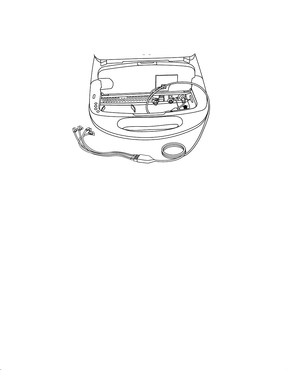
Figure 1. Programmer components - front view
1 Telephone cord (not supplied)
2 Emergency VVI button
3 Microphone jack
4 Display screen
5 Headphone jack
6 Power cord
7 Printer paper
8 Printer controls
9 Keyboard cover
10 Keyboard
11 Disk drive, PC card cover
12 Reference guide
13 Programming head (ordered separately)
14 Touch pen
15 Electrode leads
16 ECG cable with plug
17 Ethernet cable (not supplied)
Note: Only accessories approved by the manufacturer should be used.
Display screen – Display can be positioned smoothly from closed to nearly horizontal.
Programming options are selected on the screen with the touch pen.
Reference Manual 21

Medtronic MEDTRONIC CARELINK® 2090
Emergency VVI button – Used to deliver bradycardia VVI operation.
Microphone jack – Intended for future use.
Headphone jack – Intended for future use.
Keyboard cover – Slides forward to protect the keyboard.
Keyboard – Used to enter information.
Printer controls – Select paper speeds of 12.5, 25, or 50 mm/s. Push a button once to
select printing speed. Push it again to stop printing. The Paper Advance button allows the
user to align the paper properly.
Telephone cord – Connects the programmer modem to a telephone jack. The telephone
cord must be 26 wire gauge minimum. (Not supplied by Medtronic.)
Ethernet cable – Used to connect the programmer to the clinic’s network. The Ethernet
cable must be Category 5 or better. (Not supplied by Medtronic.)
Printer paper – Paper for the internal printer.
Programming head – Provides the communication link between the programmer and the
patient’s implantable device. The programming head contains a strong permanent magnet,
radio-frequency (RF) transmitter and receiver, and light array. It must be held over the
implantable device during a program or interrogate operation. (Ordered separately; not
supplied with the programmer.)
Touch pen – Used to select options on the display screen. Predetermined options are
selected by applying the pen to the screen.
Electrode leads/ECG cable – Connects the programmer to skin electrodes on the patient
for ECG and measurement functions requiring surface detection of cardiac and implantable
device signals. Five color-coded lead wires connect the cable to standard, disposable skin
electrodes applied to the patient. (Not supplied by Medtronic.)
Note: If you are using a five-lead cable with a plug, the plug can be removed for five-lead
ECG applications.
Reference guide – Programmer Reference Guide, provides information about setting up
the programmer and between session features.
Disk drive, PC card cover – Provides access to the disk drive and the PC card. If applicable
to your programmer hardware, also provides access to USB port(s) and either Integrated
Ethernet or parallel connector.
Power cord – Connects the programmer to an AC power outlet.
22 Reference Manual

Medtronic MEDTRONIC CARELINK® 2090
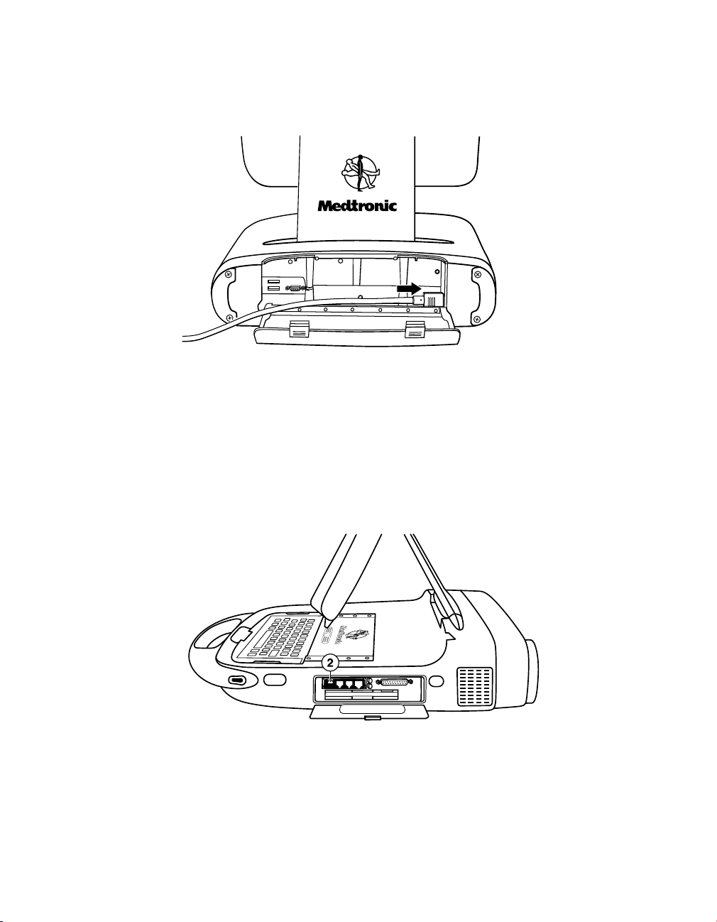
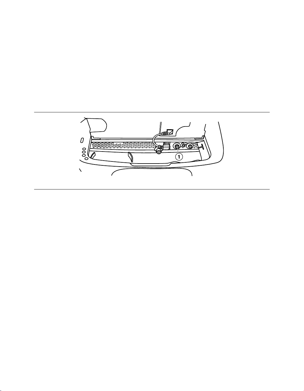
Figure 2. Front connectors (keyboard turned up)
1 Programming head (yellow marker)
2 Analog Input/Output (green marker)
3 ECG cable (black or blue marker)
Programming head – The programming head connector has a yellow marker.
Analog Input/Output – Allows an external monitor or recorder to be connected to the
programmer. This connector has a green marker.
ECG cable – Connects the ECG cable to the programmer. This connector has a black or
blue marker.
Figure 3. Left view
1 ON/OFF switch
2 Cooling fan
3 Expansion slot (shown with Analyzer
installed)
4 Printer
ON/OFF switch – Controls power (AC) to the programmer. Once the programmer is turned
off, wait 2 seconds before turning it on again.
Cooling fan – Internal fan provides continuous airflow to prevent the internal circuitry from
overheating.
Reference Manual 23

Medtronic MEDTRONIC CARELINK® 2090
Expansion slot – Allows for additional features to be added, such as the Analyzer that is
available as an option.
Printer – Integral thermal printer with text and graphic output capabilities. According to the
selected function, the printer provides data reports or it can print out a continuous ECG with
accompanying Marker Channel telemetry, EGM, or both when available.
Figure 4. Right view
1 Disk drive, PC card cover
2 Infrared window
Disk drive, PC card cover – Provides access to the disk drive and the PC card. If applicable
to your programmer hardware, also provides access to USB port(s) and either Integrated
Ethernet or parallel connector.
Infrared window – Intended for future use.
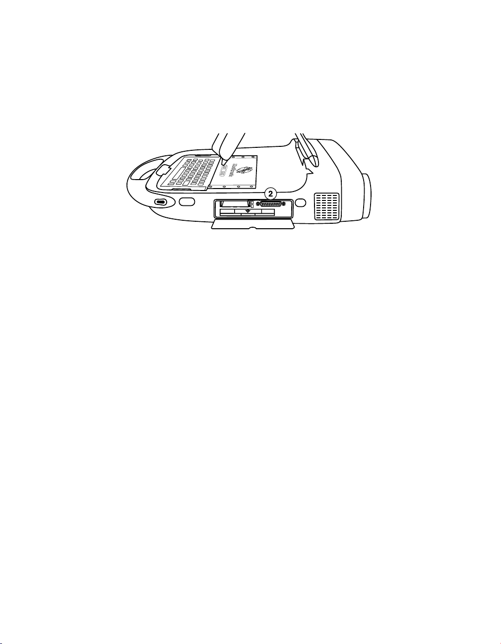
Figure 5. Disk drive, with parallel connector, PC card cover open
1 PC card slot
2 Parallel connector
3 Disk drive
24 Reference Manual

Medtronic MEDTRONIC CARELINK® 2090
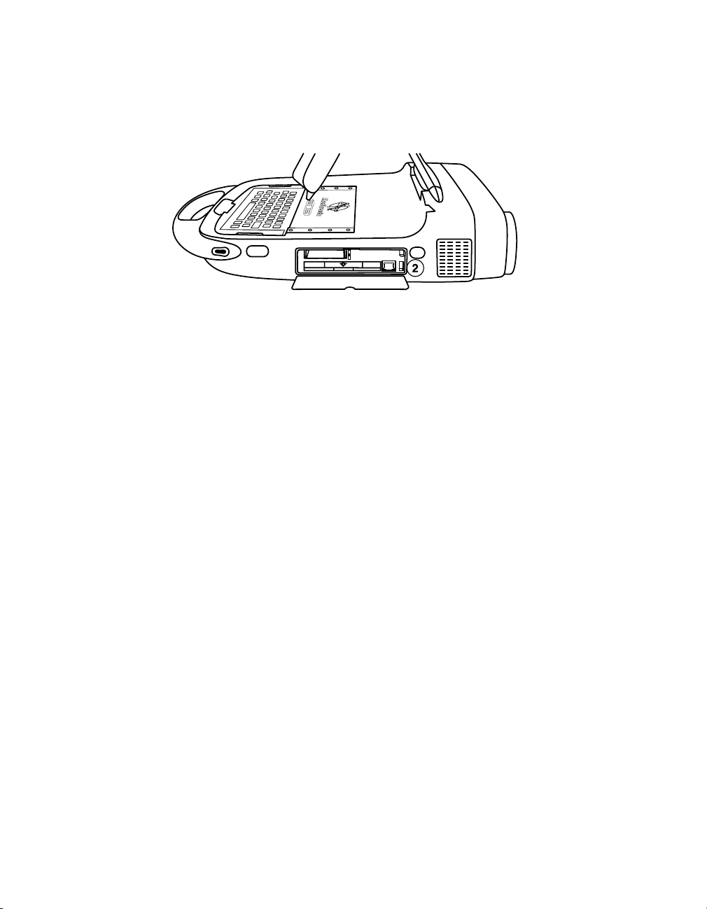
Figure 6. Disk drive, with USB port, PC card cover open
1 PC card slot
2 Disk drive
3 Integrated Ethernet
4 USB port
PC card slot – There are different types of PC cards that can be plugged into the PC card
slot:
●
The Modem card.
●
The Combination Ethernet/Modem Network card, referred to as the combo card.
These PC cards can be used to connect to the Software Distribution Network or to connect
the programmer to a consultant’s computer.
Warning: When using a modem or combo card, make sure that the telecom voltage does not
exceed 125 V. Excessive voltage may damage the programmer.
Parallel connector – Allows a printer to be connected to the programmer.
Disk drive – Accommodates a 90 mm formatted diskette that is IBM-compatible.
Integrated Ethernet – Allows the programmer to connect to the Software Distribution
Network and the Paceart data management system using an Ethernet connection.
USB port(s) – Allows installation of software, software updates, and future device
application installations. The USB port can also be used to connect to a USB printer, a USB
flash drive, or a USB network adapter (contact a Medtronic service representative).
Reference Manual 25

Medtronic MEDTRONIC CARELINK® 2090
Figure 7. Back view (power cord door open)
1 USB port(s)
3 Power cord
2 VGA output port
VGA output port – Allows porting the screen image of the programmer to an external VGA
monitor or for conversion of the output signal to NTSC/PAL format for presentation on a
television monitor.
Power cord – Connects the programmer to an AC power outlet.
2.2 Basic setup
Before setting up the programmer, select a sturdy location for it without blocking the air vents
on the right and left sides. The programmer uses a power cord, so the location must be near
an AC outlet.
This section describes how to:
●
Position the display
●
Connect the ECG cable
●
Connect the programming head
●
Connect the power cord
●
Connect the telephone line
●
Connect the Ethernet cable
●
Turn on the programmer
●
Troubleshoot potential interference
26 Reference Manual

Medtronic MEDTRONIC CARELINK® 2090
2.2.1 Position the display
1. Press inward on the two buttons on each end of the handle.
2. Lift the display
3. Place it at a comfortable viewing angle.
Reference Manual 27
Medtronic MEDTRONIC CARELINK® 2090
2.2.2 Connect the ECG cable
1. Slide the keyboard cover all the way back. Press the latch and flip up the keyboard.
2. Line up the arrow on the ECG cable with the red dot on the ECG connector.
3. Plug the cable into the connector with the black or blue marker on the right.
4. Flip down the keyboard, making sure that the cable passes through the notch on the
right or left side.
2.2.3 About the ECG cable
The Medtronic Model 2090 EC/ECL ECG cable and lead wires connect the programmer to
skin electrodes for ECG and measurement functions requiring surface detection of cardiac
and implantable device signals.
The ECG cable is designed for use with five lead wires. However, some physicians prefer to
use only four lead wires. If four lead wires are used, insert the chest ECG plug into the middle
cable port of the ECG cable.
Note: Improper insertion of the cable plug may damage the connector pins.
28 Reference Manual

Medtronic MEDTRONIC CARELINK® 2090
Cautions:
●
Upon opening the package, if the ECG cable appears damaged, do not use it. Contact
your local Medtronic or Vitatron representative.
●
Do not pull on the insulated cable wire to disconnect the cable. Tension on the insulated
cable wire may result in damage to the cable.
2.2.4 Connect the programming head
1. Slide the keyboard cover all the way back. Press the latch and flip up the keyboard.
2. Line up the red dots on the programming head cable and the programming head
connector.
3. Plug the cable into the programming head connector with the yellow marker on the left.
4. Flip down the keyboard, making sure that the cable passes through the notch on the
right or left side.
Reference Manual 29
Medtronic MEDTRONIC CARELINK® 2090
2.2.5 Connect the power cord
1. Open the back cover by pressing both latches.
2. Plug the power cord into the programmer.
3. Plug the power cord into AC power outlet. The programmer automatically adjusts to the
available line power.
4. Make sure the power cord passes through the notch on the left side and close the cover.
2.2.6 Connect the telephone line
1. Locate the disk drive/PC card cover on the right side of the programmer and flip down
the cover.
2. Connect the telephone line to the RJ-11 connector on the modem card or combo card.
(The combo card is shown.)
30 Reference Manual

Medtronic MEDTRONIC CARELINK® 2090
3. Connect the opposite end of the telephone line to an analog telephone jack.
4. If you replaced the card, reboot the programmer before using it.
2.2.7 Connect the Ethernet cable (as applicable to your hardware)
1. Locate the disk drive/PC card cover on the right side of the programmer and flip down
the cover.
2. Connect the Ethernet cable to the Integrated Ethernet connection.
3. Alternatively, the Ethernet cable can be connected to the RJ-45 connector on the
combo card instead of using the integrated Ethernet connection.
4. Connect the opposite end of the Ethernet cable to a network jack.
2.2.8 Turn on the programmer
Reference Manual 31

Medtronic MEDTRONIC CARELINK® 2090
1. Locate the ON/OFF switch on the left side of the programmer.
2. Press inward on the top of the ON/OFF switch.
2.2.9 About turning on the programmer
The first time the programmer is turned on following one of these changes, the start-up takes
2 minutes:
●
When a new keyboard language is installed
●
When the keyboard is removed (the programmer has been previously turned ON with a
keyboard)
●
When a keyboard has been added (the programmer has been previously turned ON
without a keyboard)
●
When the PC card has been removed (the programmer has been previously turned ON
with a PC card)
●
When a PC card has been added (the programmer has been previously turned ON
without a PC card)
2.2.10 Troubleshoot potential interference
To address possible harmful interference between the programmer and other devices, you
are encouraged to take one or more of the following measures to address the situation:
●
Reorient or relocate the devices.
●
Increase the separation between the devices.
●
Connect the equipment to an outlet on a different circuit.
●
Consult Medtronic or Vitatron for help.
2.3 Connect peripheral devices
An analog input/output connector under the keyboard allows the use of a peripheral isolated
medical grade recorder or monitor. A special adapter accessory (not included with the
programmer) is needed to use the input/output connector. Contact your Medtronic or
Vitatron representative for more information. The signals present at the output depend on the
software application, but may include the following:
●
ECG
●
Marker Channel telemetry
32 Reference Manual
Medtronic MEDTRONIC CARELINK® 2090
●
EGM
●
Software-specific waveforms
All electronic devices that are connected to the programmer must meet the electrical safety
requirements of IEC-60950-1.
2.3.1 Locate the peripheral device connector
Figure 8. Locating the peripheral device connector
1 Analog Input/Output connector with green marker (under the keyboard)
2.4 Use external printers
Connecting a compatible printer to the programmer allows you to print full, page-size reports
of session data when available. For more information, see the reference guide for the
implanted device. This section describes how to connect a printer to your programmer.
All printers listed by this software are certified to IEC 60950, UL 60950 or equivalent. Only
printers listed by this software may be connected to the programmer.
2.4.1 Printer compatibility
The programmer is compatible with many printers. A list of compatible printers can be
accessed from the Print Queue screen.
Note: When programming a Vitatron device, refer to the applicable Vitatron reference guide
for information about printing.
Reference Manual 33
Medtronic MEDTRONIC CARELINK® 2090
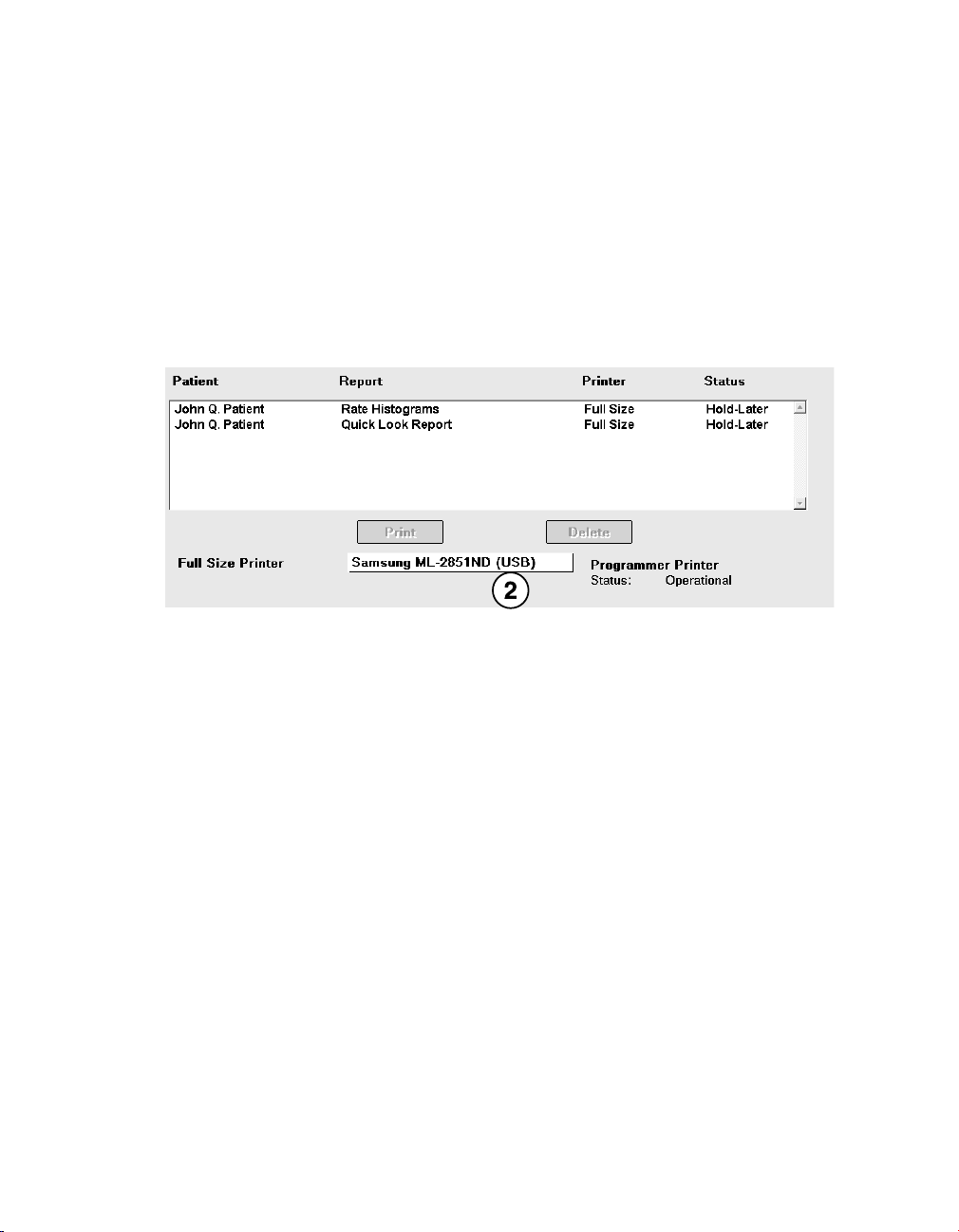
2.4.2 View a list of supported printers
Some devices only support the internal programmer printer. In these cases, the Print Queue
window is not displayed during a session; it is displayed from the desktop when not in a
session. Refer to the applicable device reference guide.
For those devices that support an external printer, refer to the following procedure.
1. If you are conducting a patient session, press the Reports icon, and then select
Print Queue.
If you are not conducting a patient session, press the Print Queue icon.
2. On the Print Queue screen, select the Printer field to open the list of supported printers.
2.4.3 Materials you need
To connect a printer to the programmer, you need a USB printer cable or a Parallel Interface
printer cable. For a USB printer cable, one end must be a USB Type A connector. The other
end of the cable must fit the USB port on your printer. For a Parallel Interface printer, one end
of the cable must fit the parallel interface port on your printer. The other end of the cable must
be a standard 25-pin male D connector.
2.4.4 Connect the printer
Before connecting a printer to your programmer, exit the patient session and turn off the
programmer.
Note: The connection method you use depends on your programmer hardware.
34 Reference Manual
Medtronic MEDTRONIC CARELINK® 2090
2.4.4.1 Connect to a programmer that supports both parallel and USB printing
The following steps apply to programmers with hardware that support both parallel and USB
printing.
1. To connect a printer, locate the correct port.
●
For USB cable printers, use a USB port located in the power cord compartment of
the programmer.
●
For Parallel Interface printers, the Parallel Interface port is located under the disk
drive/PC card cover on the right side of the programmer. Open the cover by pushing
down on the small latch at the top center of the panel.
2. Connect the printer cable to the USB port or parallel connector on the programmer.
3. Connect the other end of the cable to the printer. Connect the printer power cord to an
outlet and turn on the printer. Make sure that the printer has paper.
Note: Refer to the technical information provided with your printer for information about
connecting and operating the printer.
4. Turn on the programmer and select the Print Queue icon.
Note: Be sure to select the correct printer driver from the options listed when you select
the Printer field on the Print Queue window. You are now ready to use your programmer
with the connected printer.
Reference Manual 35
Medtronic MEDTRONIC CARELINK® 2090
2.4.4.2 Connect to a programmer that supports only USB printing
The following steps apply to programmers with hardware that supports only USB printing.
1. To connect a printer, locate the correct port. There is one USB port located under the
disk drive/PC card cover and two ports located under the power cord door on the back
of the programmer.
2. Connect the printer cable to a USB port on the side or back of the programmer.
3. Connect the other end of the cable to the printer. Connect the printer power cord to an
outlet and turn on the printer. Make sure that the printer has paper.
4. Turn on the programmer and select the Print Queue icon.
Note: Be sure to select the correct printer driver from the options listed when you select
the Printer field on the Print Queue window. You are now ready to use your programmer
with the connected printer.
2.5 Install printer paper
The internal printer requires a special thermal paper supplied in flat packs. You may obtain
this paper directly from Medtronic or Vitatron. One package of printer paper contains six
individual packs of paper. Each pack contains approximately 200 perforated sheets.
36 Reference Manual
Medtronic MEDTRONIC CARELINK® 2090
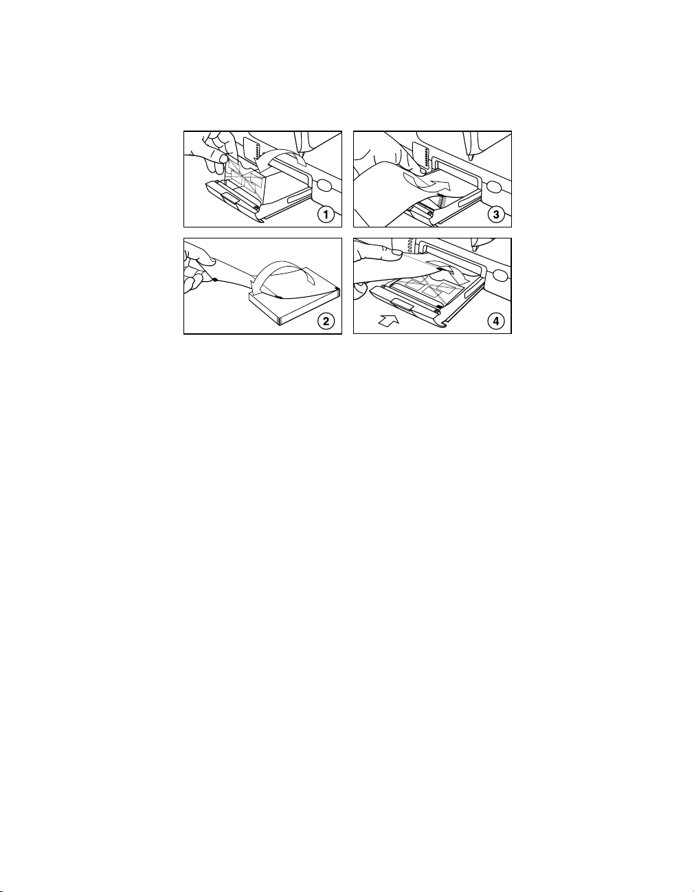
2.5.1 How to load printer paper
1. Press the latch on the top of the tray on the left side of the programmer. Slide the tray out.
Flip the paper holder over the end of the tray and remove any remaining paper.
Note: The tray may be taken out of the programmer to make removing any remaining
paper easier. Press down on the lever on the side of the tray toward the front of the
programmer.
2. Remove the wrapping from a new flat pack of printer paper, dispose of the cardboard,
and unfold the top sheet.
Note: The shiny side of each sheet of paper with two black squares should be facing up
as the paper is loaded into the tray. The black squares must be positioned toward the
front of the programmer.
3. Slide the paper pack toward the back of the tray. Flip the paper holder over the paper
pack.
4. Fold the top sheet of paper over the paper holder. Slide the tray back into position.
Reference Manual 37
Medtronic MEDTRONIC CARELINK® 2090
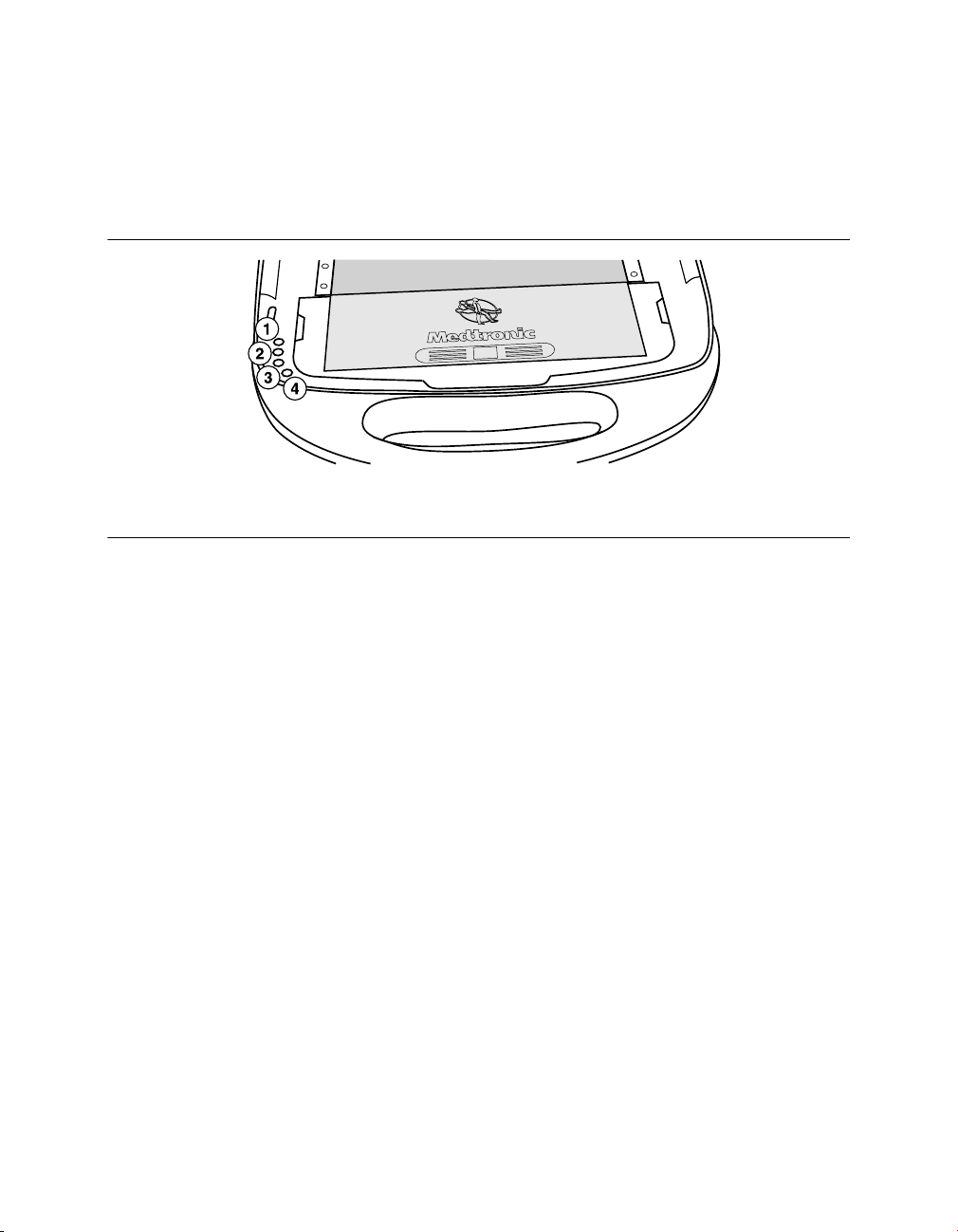
2.6 Printer buttons
The following four buttons control certain printer functions.
Figure 9. Printer buttons
1 50 mm/s
2 25 mm/s
50, 25, or 12.5 mm/s – Three buttons allow for selection of a desired paper speed for ECG,
Marker Channel telemetry, and EGM recording. Pressing a button selects the printer speed
and turns on the indicator light. Pressing a lit button stops the printout. The selected paper
speed is printed once along the top edge of the chart recording. Paper speed for text printing
is not affected by these buttons.
Paper Advance – Pressing Paper Advance advances the printer paper to its next
perforation for tearing off.
3 12.5 mm/s
4 Paper Advance
2.7 Tear off a printout
To tear off a printout, separate the paper strip at a perforation. To tear off the printout at the
printer, press Paper Advance. This action advances the paper to the next perforation. Grasp
the printout near the printer, and pull.
38 Reference Manual

Medtronic MEDTRONIC CARELINK® 2090
Figure 10. Tearing off printouts
2.8 Low paper supply
As the paper supply nears its end, a red stripe appears along the edge of the paper. A new
paper pack should be installed as previously described in this chapter. When the paper
supply runs out, the printer stops operating.
Note: The thermal paper used in this programmer is intended for immediate use. As the
quality of thermal paper diminishes over time, the image fades. Medtronic and Vitatron
recommend that you make photocopies for your files.
Reference Manual 39

Medtronic MEDTRONIC CARELINK® 2090
3 Configure the programmer
3.1 Display screen features
The programmer display screen is an interface that displays text and graphics. It is also a
control panel that displays buttons and menu options that you can select using the touch pen.
3.1.1 Features and conventions of the display screen
This section provides an overview of the features of the display screen. For more information,
see the reference guide for the implanted device. The main elements of a typical display
screen before you select a model, when you turn the programmer on, and when you end a
patient session, are shown in Figure 11.
Figure 11. Main elements of the display screen
1 Task bar
2 Status bar
3 Live Rhythm Monitor window
4 Waveform adjustment bars
40 Reference Manual
5 Task area
6 Command bar
7 Buttons
8 Tool palette

Medtronic MEDTRONIC CARELINK® 2090
Vitatron display screens may be different. For more information, see the reference guide for
the implanted device. If you see a Medtronic/Vitatron switch button, press it to display the
Vitatron Select Model screen.
3.1.1.1 Task bar
The task bar can contain these icons/indicators:
Table 1. Task bar icons/indicators
Icon Name Function
Position head light
array
SessionSync icon Provides information about the connection and data
Diskette indicator Turns green to indicate diskette drive is available for sav-
USB indicator Turns green to indicate USB flash drive is available for
RemoteView icon Provides information about the connection between the
Analyzer indicator/selector
Device indicator/selector
Turns green to indicate successful communication
between the programming head and the device. The
greater the number of green bars on the array, the better
the communication. A minimum of two green bars should
be lit.
transfer status between the Programmer and the data
management system. SessionSync is an optional feature. If your device does not support SessionSync, a red
symbol will be superimposed over the icon. For more
information, see Section 8.1.
ing PDF reports and patient data. When diskette indicator is green, USB flash drive is not available.
saving PDF reports and patient data. When USB indicator is green, diskette is not available. When inserting a
USB flash drive, you may experience a slight delay
before device is available for use.
programmer and the remote system. Allows the user to
initiate and terminate a RemoteView connection, and
indicates if the RemoteView feature is available. The icon
changes to indicate the connection status between the
programmer and the remote system. For more information, see Section 7.2.
Used to start an analyzer session or, if your device supports concurrency, to switch to an analyzer session from
a patient session. During an analyzer session, the indicator box turns green. (For more information on the
optional Analyzer, see the 2290 Analyzer Reference
Guide.)
Used to go to the Select Model screen on the programmer desktop or, if your device supports concurrency, to
switch to a patient session from an analyzer session.
During a patient session, the indicator box turns green.
Reference Manual 41

Medtronic MEDTRONIC CARELINK® 2090
3.1.1.2 Status bar
Before selecting a model, the status bar has no information. For specific information about
the status bar, refer to the reference guide for the implanted device. After model selection,
the status bar may include:
●
The present pacing mode.
●
Test condition status.
●
The device model.
3.1.1.3 Live Rhythm Monitor window
This window is a partial view of the full-screen display of the ECG, and contains a Status bar
and a Waveform adjustment bar that allows you to change the waveform display. You can
expand this window to full size by selecting the small square button in the upper-right corner
of the window or by pressing [Adjust…].
After model selection, Marker Channel and telemetered EGM waveform traces may be
available.
Refer to the appropriate reference guide for the implanted device for more information about
the Live Rhythm Monitor. Refer to the 2290 Analyzer Reference Guide for information about
the controls on the Waveform Adjustment bar.
3.1.1.4 Task area
The portion of the screen between the Live Rhythm Monitor window near the top of the
screen and the command bar at the bottom of the screen changes according to the task or
function you select.
3.1.1.5 Command bar
The bar at the bottom of the screen shows the command buttons for automatically launching
the proper software application and displaying the Vitatron Select Model screen. For
information on what command buttons are available after selecting a model, see the
reference guide for the implanted device.
3.1.1.6 Buttons
Buttons allow you to operate the programmer using the touch pen. You can “press” a button
by touching it with the tip of the touch pen.
42 Reference Manual

Medtronic MEDTRONIC CARELINK® 2090
Buttons may directly execute a command, such as [Freeze], or they may open a window that
prompts another action. Buttons that open a window usually have a label ending with an
ellipsis, such as [Strips…] or [Adjust…].
A procedure may instruct you to “press and hold” a button. Press the tip of the touch pen to
the button and maintain pressure until it is time to “release” the button.
When a button is inactive, it appears a lighter color and does not execute a command when
you press it with the touch pen.
3.1.1.7 Tool palette
The collection of buttons and icons along the edge of the screen is referred to as the “tool
palette”. These buttons and icons are the controls you use to choose the task or function
screen you want to display. Each of the icons acts like a button. To select an icon, touch the
icon with the touch pen. For more information, see Section 3.2. For information about the
session tool palette, see the reference guide for the implanted device.
3.2 About the Between Patient Sessions tool palette
The Between Patient Sessions tool palette is located on the Select Model screen. The Select
Model screen appears before you select a model, when you turn the programmer on, and
when you end a patient session.
The tools that are available between patient sessions are described in Table 2.
Note: When programming a Vitatron device, refer to the applicable reference guide for
information about the tool palette.
Table 2. Between Patient Sessions tool palette.
Tool Selecting the tool (button or icon)…
Freezes a segment of the live rhythm display.
Note: A frozen strip can be viewed, printed, or saved to PDF (but not saved
to diskette or USB flash drive) between patient sessions. Markers and
EGM traces are not present between patient sessions.
The [Strips…] button is not available between patient sessions. Saved
rhythm strips can only be accessed during a patient session.
Opens a window of options for adjusting the live rhythm display.
Note: Additional adjustment options are present during a patient session.
Displays the screen for selecting a model and starting a patient session.
Reference Manual 43

Medtronic MEDTRONIC CARELINK® 2090
Table 2. Between Patient Sessions tool palette. (continued)
Tool Selecting the tool (button or icon)…
Displays a queue of print requests from previous sessions as well as frozen waveform reports requested between sessions. Refer to the reference
guide for the implanted device to determine if these features are available.
Displays the programmer setup options.
Preferences
Time and Date
Artifact Detection
Software
Demonstrations
Programmer Profile
SessionSync Status
SessionSync Network Configuration…
RemoteView Network Configuration…
Network Configuration
Other Software
Tools
Licensing
Selects the Analyzer for analyzing the electrical performance of a cardiac
lead system (requires optional hardware - for more information, see
the 2290 Analyzer Reference Guide.)
Note: When some functions are active on the display, pressing a tool button or icon has no
effect. Closing the active window restores operation of the tool palette.
3.3 View and update programmer location and hardware information
Information about the location of the programmer and its hardware is on the Programmer
Profile screens.
The Programmer Profile location screen has the following information:
●
Clinic’s name, address, telephone number, contact person, and customer account
number
●
Service representative’s name, telephone number, fax number, and e-mail address
The Programmer Profile hardware screen has the model number for the Analyzer, and model
and serial numbers for the programmer and the programming head.
Information on the screen may be updated by selecting the appropriate field and then using
the keyboard.
44 Reference Manual

Medtronic MEDTRONIC CARELINK® 2090
3.3.1 Verify Programmer Profile information
Each programmer has a profile screen that contains identifying information about the
installed hardware, the programmer location, and contact information for the Medtronic
service representative.
Typically, the profile is completed when the programmer is first installed, and then updated
only when necessary.
1. Press the Programmer icon, and then select Programmer Profile. Location
Information appears by default.
2. Complete the location information or verify that the information shown is correct.
3. To view hardware information, select Hardware Information.
Figure 12. Programmer Profile screen
3.4 Adjust programmer time and date
If the time or date displayed and printed by the programmer is incorrect, use the following
procedure to enter the correct settings. For Vitatron devices, see the applicable reference
guide.
Reference Manual 45

Medtronic MEDTRONIC CARELINK® 2090
3.4.1 Set the time and date
1. Press the Programmer icon, and then select Time and Date.
2. From the Programmer Time and Date screen, press the up or down button to increase
or decrease the value for the unit of time that you want to change. Press and release the
button for single unit changes, or press and hold the button to make larger changes.
3. When all fields show the correct time and date, press [Apply]. Select another tool
palette icon to close the Programmer Time and Date screen.
Figure 13. Programmer Time and Date screen
Note: Time must be entered based on a 24-hour clock, with 00:00 being midnight, and
12:00 being noon.
3.5 Select audible tones
Certain events in the operation of the programmer result in an audible signal. The following
tones alert you to the success or failure of an action.
●
A two-tone beep (low-to-high) indicates confirmation of a successful Interrogate or a
Program command.
●
A double low-tone beep indicates that an Interrogate, Program, or Emergency
command was not confirmed. It can also indicate that the selected command cannot be
executed.
46 Reference Manual

Medtronic MEDTRONIC CARELINK® 2090
Note: For some devices, the tones may not be turned off. For more information, see the
reference guide for the implanted device. For Vitatron devices, see the applicable reference
guide.
3.5.1 Turn tones on or off
1. Press the Programmer icon, and then select Preferences.
2. From the Preferences screen, select [Audio ON] or [Audio OFF] as desired.
Figure 14. Audio Preferences screen
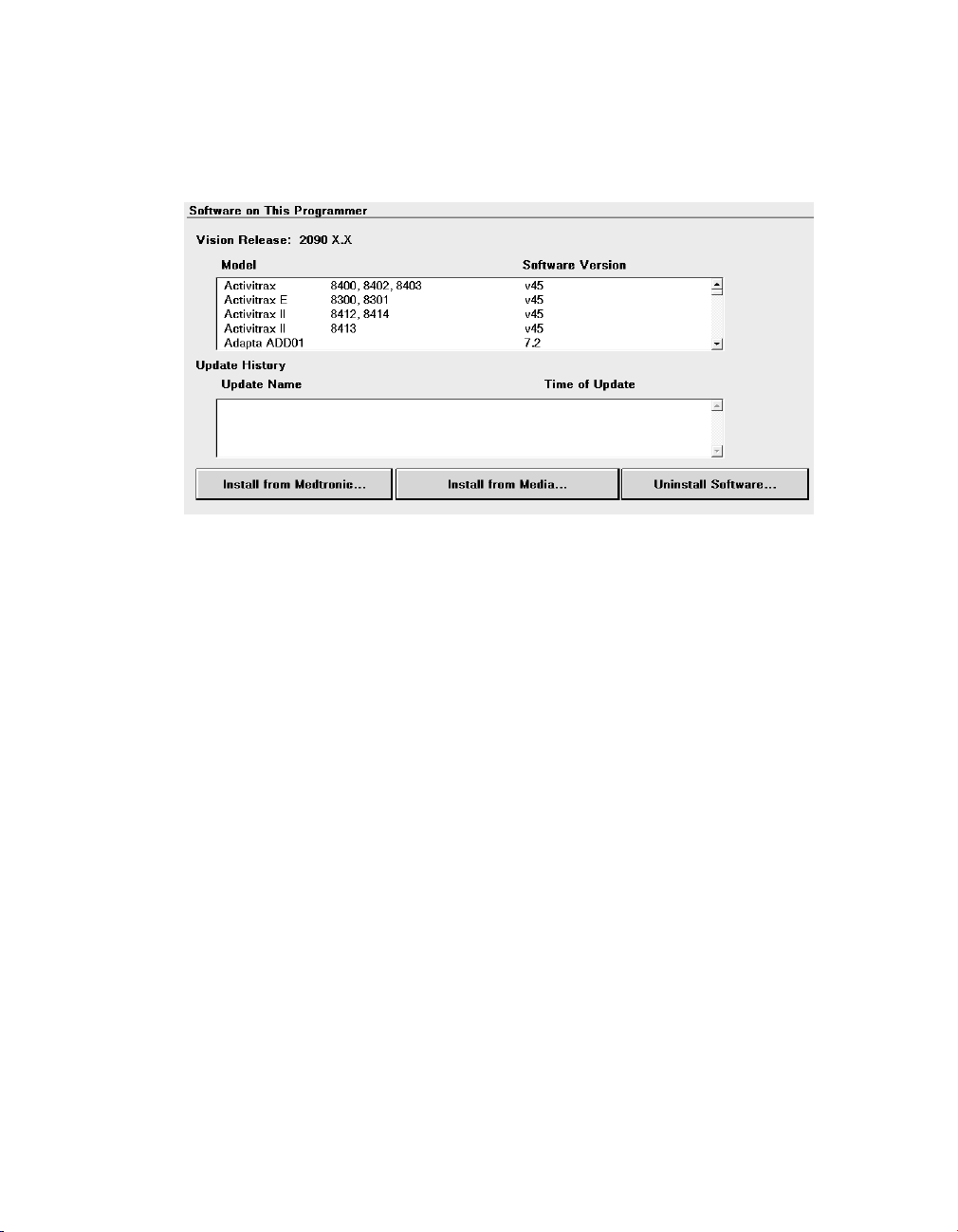
3.6 Check the software version
This section describes how to determine the version of software that is loaded on the
programmer.
If you need to know what version of software is currently loaded on the programmer for any
of the device models, use the following procedure.
For Vitatron devices, see the applicable reference guide.
3.6.1 To check the software version number
1. Press the Programmer icon, and then select Software.
2. For each device model with software loaded on the programmer, the screen displays
the software version number next to the model number.
Reference Manual 47

Medtronic MEDTRONIC CARELINK® 2090
Figure 15. Software on This Programmer screen
Note: If the model that you require is not displayed, the software to support that model is not
currently loaded on the programmer. Contact your Medtronic or Vitatron representative.
3.7 Select other software
In addition to the standard application software, there are some programmers that have
other applications installed. These applications may include supplemental software or
software used in clinical studies for research. If you have other software installed, you may
access the software, using the following procedure.
1. Press the Programmer icon, and then select Other Software.
2. When the programmer displays the list of available software, select the application and
press [Start].
3.8 Remove other software applications
Programmers with other software installed, such as supplemental software or those used in
clinical studies for research, may allow the applications to be removed from the programmer
desktop. If you have software installed that permits removal, you may remove it using the
following procedure.
1. Press the Programmer icon, and then select Software.
2. Press [Uninstall Software…].
48 Reference Manual

Medtronic MEDTRONIC CARELINK® 2090
3. When the programmer displays the list of removable software, select the application to
be removed, and then press [Uninstall].
4. Select the check box next to the acknowledgment statement, and then press
[Continue].
5. The software is removed, and the programmer reboots.
6. Verify that the software has been removed.
3.9 Improve the detection of pacing artifacts
The Artifact Detection function allows you to improve the detection of pacing artifacts when
interference causes either false artifacts or no artifacts to appear on the patient’s ECG.
Pacing artifacts are displayed on the patient’s ECG when the artifact detection option (Show
Artifacts) has been enabled.
To determine if this feature is applicable, see the reference guide for the implanted device.
3.9.1 Enable artifact detection
1. Press the Programmer icon, and then select Artifact Detection.
2. Make sure the current settings include ARTIFACT DISPLAY IS ON.
3. Make sure the current settings include MV FILTER IS ON.
3.10 Start the Demonstrations option
The demonstrations option allows you to run a demonstration program on the programmer.
For Vitatron devices, see the applicable reference guide.
Note: Device applications and reference manuals may still refer to using the “demonstration
disk” or “demonstration diskette” to run a demonstration program. The need for a
demonstration diskette to access demonstration mode is no longer required. All references
to a demonstration diskette can be ignored. If a demonstration diskette is inserted
inadvertently, operation of the demonstration mode is not affected. All demonstration mode
features are accessible with or without a demonstration diskette.
Reference Manual 49

Medtronic MEDTRONIC CARELINK® 2090
3.10.1 Access demonstrations
1. Press the Programmer icon, and then select Demonstrations.
2. From the Demonstration Model Selection screen, select the desired View option to list
the available demonstration programs.
3. Select the desired demonstration program and press [Start].
50 Reference Manual

Medtronic MEDTRONIC CARELINK® 2090
4 Update programmer software using the Software Distribution Network
4.1 The Software Distribution Network
Programmer software can be updated by Medtronic customers or Medtronic personnel by
accessing the Medtronic Software Distribution Network (SDN) and downloading the
software. The SDN uses a world-wide network to connect to servers in the United States.
These servers are able to download software to many programmers simultaneously through
secure connections.
The SDN is available 24 hours per day, 7 days per week and always contains the most current
software. For this reason, it is recommended that you download the software from the SDN
rather than from the flash drive.
You can connect to the SDN using a network connection (wired or wireless) or a dial-up
connection. It is recommended that you use a network connection whenever possible, since
software downloads are faster using a network connection than using a dial-up connection.
Notes:
●
It is recommended that the SDN be checked on a regular basis. Checking regularly
reduces the size of the download and the time it takes to receive the software.
●
If the download was interrupted, the download will resume the next time the programmer
attempts to access the SDN.
●
Normal programmer functions are unavailable during software installation.
4.2 Connect to the SDN using a network connection
You can connect to the SDN using your clinic’s network. By connecting through your network,
software download time can be reduced.
Before you begin, make sure your network connection is configured properly.
Reference Manual 51
Medtronic MEDTRONIC CARELINK® 2090
4.2.1 How to connect to the SDN using a network connection
1. Press the Programmer icon, and then select Software.
The programmer displays the Software on This Programmer screen and lists the
software already installed on the programmer. For each model, the screen displays the
software version.
Note: The SDN cannot be accessed from Vitatron screens. Change to the Medtronic
Select Model screen.
2. Press [Install from Medtronic…].
3. Press [Accept].
or
Press [Cancel]. The download process is cancelled and the programmer redisplays the
Software on This Programmer screen.
52 Reference Manual

Medtronic MEDTRONIC CARELINK® 2090
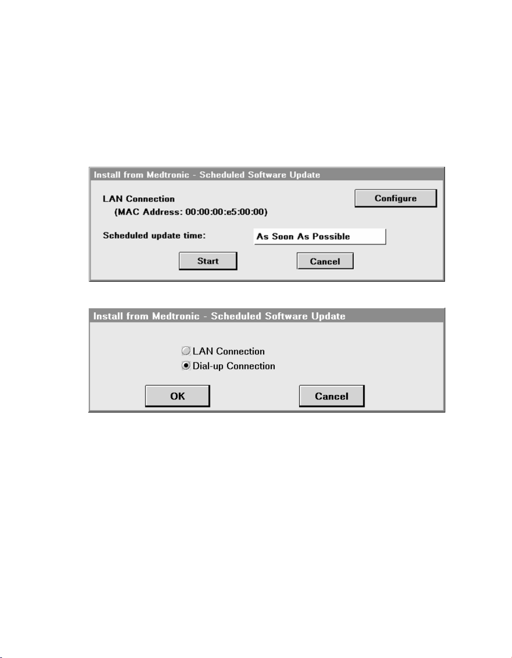
4. The programmer displays the Scheduled Software Update screen.
Either choose to start the download at a particular time by selecting a time from the
Scheduled Update Time pull-down menu, or begin the download as soon as possible
by pressing [Start].
5. The Scheduled Software Update window displays a countdown window showing how
much time remains until the download begins. Press [Start Now] to override the
countdown or press [Cancel] to interrupt the countdown and the download request and
return to the Software on This Programmer screen.
Reference Manual 53
Medtronic MEDTRONIC CARELINK® 2090
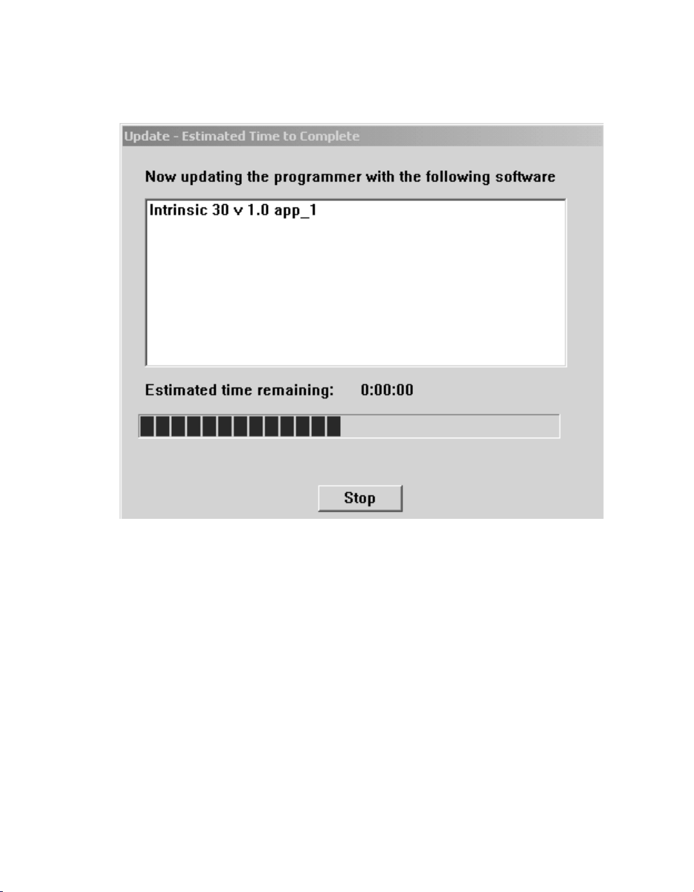
6. The programmer displays a list of software that will download and install.
Note: Individual software cannot be selected or rejected.
You may press [Stop] during the software download and resume the download at a
future time.
7. When the download is complete and the progress bar is approximately 50% filled,
software installation begins.
8. The [Stop] button disappears.
Note: Do not power-off the programmer while software is being installed.
9. When software installation is complete, the programmer disconnects from the SDN,
automatically reboots, and displays a screen listing the software that was downloaded
and installed.
10. To obtain technical manuals for the new software, see Section 1.12.1, “Access the
Medtronic Manual Library website”, page 20.
11. Press the Select Model icon. The programmer is then available for patient use.
54 Reference Manual

Medtronic MEDTRONIC CARELINK® 2090
Note: The first time the newly downloaded software is accessed, some additional
installation steps may be completed but these steps are automatic and no user intervention
is required
4.3 Connect to the SDN using a dial-up connection
You can connect to the SDN using the programmer combo card or modem card, and a
connection to an analog telephone line. In most cases, the modem connection to the SDN
can be made using a local telephone number. There is a toll-free number provided, however,
it should only be used if a local number is not available.
Before you begin, make sure that the telephone line is correctly connected to the combo or
modem card. For more information, see Section 2.2.6.
4.3.1 How to connect to the SDN using dial-up
1. Press the Programmer icon, and then select Software.
Note: The SDN cannot be accessed from Vitatron screens. Change to the Medtronic
Select Model screen.
2. For each device model with software loaded on the programmer, the screen displays
the software version number next to the model number.
3. Press [Install from Medtronic…].
Reference Manual 55
Medtronic MEDTRONIC CARELINK® 2090
4. Press [Accept].
or
Press [Cancel]. The download process is cancelled and the programmer redisplays the
Software on This Programmer screen.
5. If the programmer has the combo card installed, the Scheduled Software Update
window appears showing the LAN connection by default.
Press [Configure] to choose Dial-up Connection.
Then, select the Dial-up Connection radio button and press [OK].
The Scheduled Software Update window redisplays, now showing Dial-up Connection.
Press [Start] to continue.
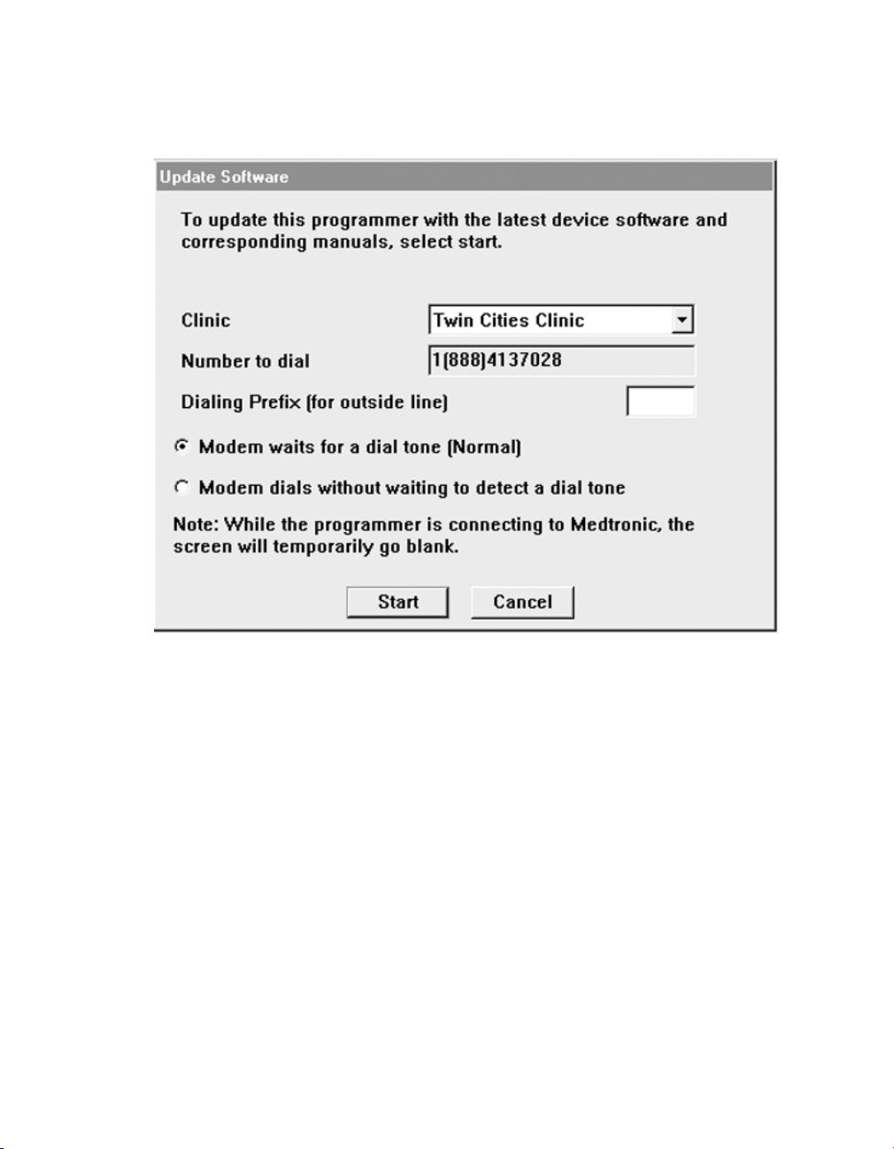
6. If the programmer has the modem card installed, the programmer automatically
displays the Update Software screen.
56 Reference Manual
Medtronic MEDTRONIC CARELINK® 2090
7. Review the Update Software screen.
To select a different clinic location, press the down arrow.
If your clinic location is not listed, refer to Section 4.3.2 for instructions on how to edit,
create, or remove a location.
8. Enter a dialing prefix, if needed.
9. Press [Start] to begin the software download.
10. While the programmer is connecting to Medtronic, the screen temporarily goes blank.
Reference Manual 57

Medtronic MEDTRONIC CARELINK® 2090
11. The programmer reboots, connects to the SDN and then displays a list of software that
will download and install.
Note: Individual software cannot be selected or rejected.
You may press [Stop] during the software download and resume the download at a
future time.
12. When software downlad is complete and the progress bar is approximately 50% filled,
software installation begins.
13. The [Stop] button disappears.
Note: Do not power-off the programmer while software is being installed.
14. When software installation is complete, the programmer disconnects from the SDN,
automatically reboots, and displays a screen listing the software that was downloaded
and installed.
15. To obtain technical manuals for the new software, see Section 1.12.1.
58 Reference Manual

Medtronic MEDTRONIC CARELINK® 2090
16. Press the Select Model icon.
The programmer is then available for patient use.
Note: The first time the newly downloaded software is accessed, some additional
installation steps may be completed but these steps are automatic and no user
intervention is required.
4.3.2 Edit locations
Part of the dial-up software download process involves confirming the programmer location
on the Update Software screen. If the clinic location does not appear in the clinic pull-down
menu or if information about an existing location needs to be changed, select Edit
Locations from the pull-down menu.
The following procedures describe how to create a new location, change an existing
location, or remove a location from the programmer.
To create, edit or remove a location, you must be on the Update Software screen. The Update
Software screen appears as one of a series of screens that are accessible only during the
software update process.
Reference Manual 59

Medtronic MEDTRONIC CARELINK® 2090
4.3.3 How to create a new location
1. Using the clinic pull-down menu, select Edit Locations. When the Edit Locations
screen appears, press [New].
2. When the new dialog window opens enter the name of the location.
3. Using the pull-down menus, identify the location by selecting the Country, Region, and
Nearest City.
4. Using the pull-down menu for Number to dial, select the number to dial to access the
SDN.
5. In the Dialing Prefix field, enter the digits of a dialing prefix, if a prefix is required to
access an outside line.
6. To set this location as the default location on the Update Software screen, select Set as
default location.
7. Press [OK] to save this location information.
8. When the Update Software screen is redisplayed, select the clinic and press [Start] to
begin the download process or press [Cancel] to exit from the download operation.
60 Reference Manual

Medtronic MEDTRONIC CARELINK® 2090
4.3.4 How to change location information
1. On the Edit Location screen use the pull-down menu to select an existing location.
Then, beginning with the Nearest City, use the pull-down menu to select a different city
if it needs to be changed.
2. To select a different SDN access number, use the pull-down menu opposite the
Number to dial field. The list of SDN access numbers shown is based on the Nearest
City selected.
3. In the Dialing Prefix field, enter the digits of a dialing prefix, if a prefix is required to
access an outside line.
4. To set the currently displayed location as the default location on the Update Software
screen, select Set as default location.
5. Press [OK] to save this location information.
6. When the Update Software screen is redisplayed, select the clinic and press [Start] to
begin the download process or press [Cancel] to exit from the download operation.
Reference Manual 61

Medtronic MEDTRONIC CARELINK® 2090
4.3.5 Remove a location
1. On the Edit Location screen use the pull-down menu to select the name of the clinic you
want to remove from the programmer.
2. Press [Remove].
3. Press [Yes] to confirm the deletion.
4. On the Edit Location screen, select the clinic to be used from the pull-down menu, then
press [OK].
5. When the Update Software screen is redisplayed, press [Start] to begin the download
process or press [Cancel] to exit from the download operation.
62 Reference Manual

Medtronic MEDTRONIC CARELINK® 2090
5 Conduct a patient session
5.1 Prepare for a patient session
Familiarize yourself with the information in this section before beginning a patient session.
5.1.1 Connect the programmer to skin electrodes
At the start of each patient session, ECG cable leads must be connected to the patient to
detect cardiac and pulse artifact signals.
Note: The quality of disposable skin electrodes used with the programmer is important to the
performance of the programmer signal sensing functions. Chemical reactions occur at the
electrode/paste interface and produce small DC voltages that can block the ECG signal.
Using high quality silver/silver chloride (Ag/AgCl) electrodes can minimize this problem.
Electrodes should be fresh and from the same box. The patient’s skin should be prepared
according to the directions provided with the electrodes.
Protocols covering attachment of leads to disposable skin electrodes may vary. Leads may
be attached to the electrodes either before or after the electrodes are applied to the patient.
The order of the following procedure is arbitrary.
Warning: Do not connect the programmer to wires or electrodes internal to the body. The
programmer is designed to be medically safe only when attached to surface electrodes.
Reference Manual 63

Medtronic MEDTRONIC CARELINK® 2090
5.1.2 Attach electrodes
Attach five standard, disposable electrodes to the patient in the positions shown.
5.1.3 Connect the ECG cable
64 Reference Manual

Medtronic MEDTRONIC CARELINK® 2090
1. As shown, attach a color-coded lead wire to each of the five electrodes. Match a color
to each electrode as in Table 3.
Note: Connecting the chest lead is optional. If the chest lead is not used, insert the
chest ECG plug into the middle cable port of the ECG cable.
2. Connect each lead wire to the ECG cable as in Table 4. Match each lead connector to
the proper cable port.
Table 3. Electrode lead wire color coding
AHA Coding
a
IEC Coding
Black Yellow to left arm
Red Green to left leg
Brown White to left chest area
Green Black to right leg
White Red to right arm
a
American Hospital Association
b
International Electrotechnical Commission
c
Connecting the chest lead is optional. If the chest lead is not used, insert the chest ECG plug into the middle cable
port of the ECG cable.
b
Body Area
c
Table 4. ECG cable color coding
AHA Coding IEC Coding
Black to LA Yellow to L
Red to LL Green to F
Brown to V
Green to RL Black to N
White to RA Red to R
a
Labeled C on some cables
a
White to C
Note: Occasionally, mutual interference occurs between the programmer skin electrode
signals and signals from an external ECG recorder or monitor attached directly to the patient.
This interference may cause erratic operation of the programmer functions that depend on
surface signal detection. If interference occurs, temporarily disconnect the leads from the
attached ECG recorder or monitor. This interference does not affect the programming
functions of the programmer.
Reference Manual 65

Medtronic MEDTRONIC CARELINK® 2090
5.1.4 Use the touch pen
The touch pen is used to select programming functions provided by the software. Proper use
of the pen is described in Figure 16 and in Section 5.1.5.
Figure 16. Using the touch pen
66 Reference Manual

Medtronic MEDTRONIC CARELINK® 2090
5.1.5 Select an option on the screen
1. Move the tip of the pen to a position directly over the desired option. If the desired option
is a displayed key or button, position the pen tip within the rectangular outline. If the
desired option is a name or number, such as a parameter or parameter value, position
the pen directly over the letters or numbers forming the option.
2. Touch the pen to the screen to select an option.
5.1.6 Use the keyboard
Certain fields on the screen allow you to enter data, such as the patient’s name or chart
number. The programmer has a compact computer keyboard for entering data.
Reference Manual 67
Medtronic MEDTRONIC CARELINK® 2090
Figure 17. Programmer keyboard
5.1.7 Position the programming head
During most applications of the programmer, the programming head must be positioned
over the implantable device. Positioning the programming head is required for any
interaction between the programmer and the implantable device.
5.1.8 When to position the programming head
Caution: Do not position the programming head over an implanted device during
electrocautery or external defibrillation procedures.
During a patient session, properly position the programming head over the implanted device
before any of the following actions:
●
Selection of any command that initiates a programming transmission. The programming
head must be held in position until completion of the transmission, which usually is
indicated by a confirmation message.
●
Selection of any command that initiates data transmission from the implantable device.
The programming head should be held steady until data reception is complete, which
usually is indicated by a confirmation message.
●
Selection of a measurement function that requires the implantable device to be
operating asynchronously as a result of the programming head magnet.
68 Reference Manual
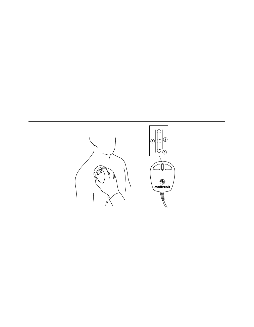
Medtronic MEDTRONIC CARELINK® 2090
For any temporarily programmed state or function or for reception of continuous data such
as Marker Channel telemetry or EGM waveforms, the programming head must be held in
place over the implantable device for the duration of the function or until termination is
desired. Lifting the programming head cancels a temporary program and terminates
continuous telemetry. The implantable device reverts to permanently programmed values.
5.1.9 Determine the correct position
For an implantable device, the programming head should be held directly against the
patient’s skin. The face of the programming head must be parallel to and typically within 5 cm
of the implantable device. Optimum position of the programming head may not be directly
centered over the implantable device.
Figure 18. Position the programming head
1 Light array
2 Green
3 Amber/green
Correct placement of the programming head is indicated in two places: the position head
array in the top left corner of the screen and the array of seven lights on the programming
head (see Figure 18).
Programming and Interrogation are not recommended when fewer than two green lights are
lit.
Reference Manual 69

Medtronic MEDTRONIC CARELINK® 2090
5.1.10 Program and interrogate the implanted device
1. Select the appropriate software parameters according to the reference guide for the
implanted device.
2. Position the programming head near the implanted device.
Programming and Interrogation can begin when the LED lights on the position head array
indicate satisfactory positioning and telemetry strength.
Notes:
●
For Medtronic devices, the programming head array shows the signal strength of the
communication link. Medtronic recommends moving the programming head to
maximize the number of green lights. All lights may not illuminate for all models. For more
information, see the reference guide for the implanted device.
●
Misalignment of the programming head could result in failure of a programming
transmission and/or failure to receive data from the implantable device. Medtronic
recommends that you interrogate the device after programming to confirm that any
setting changes were successful.
●
Reveal Plus and some older Vitatron devices respond with only one light in the position
head array. In programming mode, the light turns green, to indicate that the programming
head is in the correct position and that it is communicating with the device; the light turns
solid amber if the programming head is misaligned.
5.1.11 Use the P and I buttons
The P button and I button on the programming head (Figure 19) correspond to commands
that appear on the display screen of the programmer. Refer to the appropriate reference
manual to determine which commands the buttons correspond to. For convenience, you
may press the P button or the I button on the programming head in place of selecting the
corresponding option from the display.
70 Reference Manual

Medtronic MEDTRONIC CARELINK® 2090
Figure 19. Programming head buttons
1 P button
2 I button
5.1.12 The programming head magnet
The programming head contains a strong magnet. For more information about the effects of
a magnet, see the reference guide for the implanted device.
The programming head may attract metal instruments or may be attracted to metal surfaces.
The magnet is susceptible to partial demagnetization when it is subjected to opposing
magnetic fields, such as those present when forcing the programming head against another
magnet. The programming head should be stored as shown in Figure 21 when not in use.
Caution: Keep the programming head away from any device or material that will be
damaged by the magnetic field, including magnetic media, watches, and other electronic
devices.
5.2 Initiate a patient session
A patient session involves the application of the various programmer functions to such
procedures as programming implantable device parameters, analyzing or assessing
implantable device operation, troubleshooting, and routine follow-up. The instructions for
using each programmer function are covered in the reference guide for the implanted device.
Note: Before proceeding, ensure that all preparations covered in Section 2.2 and
Section 5.1 have been completed.
Reference Manual 71

Medtronic MEDTRONIC CARELINK® 2090
5.2.1 Programmer checklist
1. Is the programmer set up according to the procedures in Section 2.2?
2. Are the ECG cable, touch pen, and programming head connected to the programmer?
3. Does the power cord connect the programmer to an AC power outlet?
4. Has the appropriate software been installed? Refer to Section 3.6 for a description of
how to verify the software version.
5. Are the programmer ECG cable leads connected to electrodes on the patient as
described in Section 5.1.1?
Specific information related to each implantable device model or family of models is included
in the reference guide for the device.
Refer to the reference guide for the implanted device before beginning a patient session.
5.2.2 Model identification
Because the programmer collects and stores data on a session-by-session basis, it is
important to start and end each session correctly.
The programmer supports both a Medtronic and Vitatron desktop. Whichever desktop is in
use when the programmer is powered down, that same desktop appears when the
programmer is powered on. To switch from the Vitatron desktop to the Medtronic desktop
and vice versa, press the Vitatron/Medtronic switch button that appears on the bottom of the
screen.
There are two ways to begin a patient session:
●
Before turning on the programmer, position the programming head over the patient’s
device. When you turn on the programmer, the programmer attempts to interrogate the
device. Depending on the device, either the software application is launched
automatically or a message appears with further instructions.
●
After turning on the programmer, position the programming head over the patient’s
device. During the first 5 minutes, the Medtronic desktop displays the Find Patient
screen. Afterward, it displays the Select Model screen. The Vitatron desktop displays
the Select Model screen immediately. A patient session can begin at either the Find
Patient screen or the Select Model screen. Follow the instructions on the screen that is
displayed.
72 Reference Manual
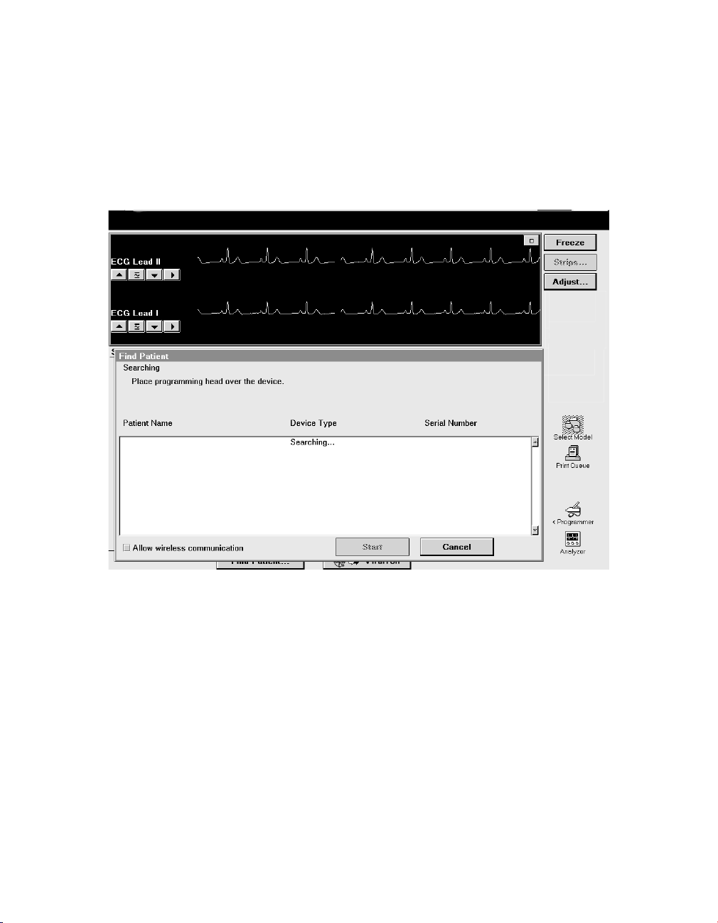
Medtronic MEDTRONIC CARELINK® 2090
5.2.2.1 Find Patient screen
When the programmer is first turned on, the Medtronic desktop displays the Find Patient
screen. If it does not detect a device within about 5 minutes, the programmer removes the
Find Patient screen to reveal the Select Model screen.
When the Find Patient screen is displayed, you may begin a patient session.
Place the programming head over the patient’s device and hold it steady. For most devices,
the programmer identifies the device model and automatically starts up the proper software
application. If a device cannot be automatically identified, the programmer displays a
message at the top of the Find Patient screen. Perform one of the following steps, depending
on the message instructions:
●
Press [Cancel] and manually select the software application from the Select Model
screen.
●
Press [Cancel] and then press the Vitatron/Medtronic switch button to go to the Vitatron
desktop.
●
If the message indicates that the needed software application has not been installed,
contact your Medtronic or Vitatron representative.
Reference Manual 73

Medtronic MEDTRONIC CARELINK® 2090
5.2.2.2 Select Model screen
A patient session may also begin from the Select Model screen. The Select Model screen
appears after one of the following actions:
●
Shortly after the programmer has been turned on
●
After you end a patient session
If the Select Model screen is not displayed, use the touch pen to press the Select Model icon.
If the Select Model icon is not displayed, a patient session is in progress. You must end that
session before starting a new session.
If you are between patient sessions, you can access other screens by using the icons and
buttons described in Section 3.2.
If the device is a Vitatron device and it is not listed on the Select Model screen, refer to the
Vitatron Software Programming Guide.
If the Select Model screen does not look like this example and you see a different button in
the command bar, press the Vitatron/Medtronic switch button to display this screen.
Position the programming head over the patient’s device and hold it steady. Press [Find
Patient] shown on the Medtronic desktop or manually select the device from the displayed
list of devices and press [Start].
74 Reference Manual

Medtronic MEDTRONIC CARELINK® 2090
When a device is manually selected from the list of devices, the programmer starts up the
application that corresponds to your selection, not the device that is under the programming
head. The Starting Application screen is displayed briefly as the programmer starts up the
proper software application. If the software application has not been installed, the
programmer displays a message indicating that the software must be installed before
proceeding.
The programmer may automatically interrogate the patient’s implanted device to retrieve
most of the data that might be needed during the session. To take advantage of this
automatic interrogation, position the programming head over the implanted device and
continue to hold it in place until the interrogation is complete.
For more information about determining the model, see the reference guide for the implanted
device.
Note: If you are using the optional Analyzer and your device does not support concurrency
with the Analyzer, you must exit the Analyzer before you can start a patient session. If you use
the task bar to switch from the Analyzer to the Select Model screen and then press [Find
Patient], the programmer displays the message: “This application is not able to run
concurrently with the Analyzer. Please exit the Analyzer and try again.”
5.3 Emergency VVI button
The red emergency VVI button on the display panel provides immediate access for
emergency VVI pacing during a patient session (Figure 20). (Specific parameter values are
determined by each application.)
●
For all Medtronic pacemaker applications, the red emergency VVI button is active when
the [Emergency] button is displayed on screen.
Note: The [Emergency] button is also implemented in the software and appears on the
display. It functions similarly to the VVI button on the panel. For more information on the
[Emergency] button, see the reference guide for the implanted device.
●
For some ICD applications, the red emergency VVI button is active at all times. When
pressed, this button delivers VVI pacing and displays the emergency screen options.
Reference Manual 75

Medtronic MEDTRONIC CARELINK® 2090
Figure 20. VVI button on the display panel
1 Red emergency VVI button
Warning: The red emergency VVI button is disabled for the following devices: PCD, Jewel
PCD, Micro Jewel II, MicroJewel, Jewel CD, Jewel Plus, Model 7202 Jewel CD, Models 7218
and 7211, Model 7201 CD, and Jewel AF. Use the touch pen to press the on-screen
[Emergency] button.
5.3.1 Deliver emergency bradycardia pacing
To initiate emergency pacing, correctly position the programming head over the implanted
device and press the red emergency VVI button. A message confirms programming, and
emergency VVI operation begins.
5.3.2 Deliver emergency tachyarrhythmia therapy
To deliver therapy, press the red emergency VVI button to display the emergency screen on
the programmer and press the on-screen [Deliver] button with the touch pen.
For specific applications, refer to the appropriate device Reference Guide, System
Reference Guide, or Clinician Manual for complete instructions regarding the use of the
[Deliver] button.
76 Reference Manual

Medtronic MEDTRONIC CARELINK® 2090
5.4 End a patient session
When you want to end a patient session, you may save data to a supported storage device
or end the session without saving.
Refer to the reference guide for the implanted device for specific information on saving
device data.
5.5 Store components
The following diagrams show the proper way to store components.
Figure 21. Storing components
Reference Manual 77

Medtronic MEDTRONIC CARELINK® 2090
6 Manage session data and reports
6.1 Session data
Patient session data may be saved to a diskette or a USB flash drive.
6.2 Reports
Depending on the implanted device model, various types of reports can be created. Refer to
the reference guide for the implanted device for specific information on report types and
contents. During an active session, reports may be printed, or saved as PDF files on a
diskette or USB flash drive. Reports held for later printing may be printed while at the desktop
or when returning to a session. Reports might not be available for later printing from the
desktop, depending on the device application and on the current print queue deletion
schedule. For more information, see Section 6.7.
6.3 Save to a PDF file
Printable reports, frozen strips, and other data may be saved to a PDF file. A PDF file is an
electronic version of a printed document; therefore, the feature is accessible under the
printing commands.
Note: The Save to PDF File feature works for all applications that can print to a full-size
printer.
To save to a PDF file, perform the following steps:
1. Open or create the report or file.
2. Press [Print…] or [Print Options…] to display the Print – Options dialog box.
Note: If the Print – Options dialog box does not display, open Preferences, and then
select the Printing: Pop up these options when any print button is selected check
box.
3. From the Print – Options dialog box, select the Printer: Full Size radio button. A list
of supported printers is displayed.
4. From the list of printers, select the Save to PDF File option. The report is saved to an
attached USB flash drive, or to a diskette, if a diskette is present in the diskette drive and
a USB flash drive is not connected. For more information on saving to USB, see
Section 6.5.
78 Reference Manual

Medtronic MEDTRONIC CARELINK® 2090
6.4 Save to diskette
For specific information on saving and reading device data using a diskette, see the
reference guide for the implanted device . The diskette drive is functional only when a USB
flash drive is not in use. Before using the diskette drive, ensure that a USB flash drive is not
connected to the programmer.
When no USB flash drive is connected, the diskette indicator is green to indicate that the
diskette drive is available for use. Inserting a diskette allows all session data and PDF file
saving operations to take place on the diskette.
6.5 Save to USB
Many device applications support the use of diskettes for saving and loading session data.
The programmer is also able to perform these operations using a USB flash drive. When a
USB flash drive is connected to the programmer, the diskette drive becomes unavailable.
Note: Device applications and reference manuals may still use the terms “disk” or “diskette”
in the context of saving and retrieving device data. When a USB flash drive is connected to
the programmer and available for use as described below, the terms disk or diskette should
be interpreted as applying to the USB flash drive, rather than the diskette.
6.5.1 Supported USB storage devices
In order to ensure the integrity and security of patient health information, it is recommended
that you use USB flash drives that are dedicated to storing programmer data only.
6.5.2 Operation
A USB flash drive should be connected or disconnected while at the desktop or in a session.
Connect a writable USB flash drive to the programmer using any available USB port. A slight
delay may occur while the USB flash drive is authorized. The USB indicator on the task bar
turns green to indicate that the USB flash drive is available for use. The diskette icon turns
gray to indicate that the diskette drive is not available.
Reference Manual 79

Medtronic MEDTRONIC CARELINK® 2090
USB flash drives should not be connected or disconnected while the following actions are in
progress:
●
Programming a device
●
Performing a Save to Disk or Media
●
Performing a Read from Disk or Media
●
Saving a report as a PDF file
Notes:
●
While a Save to Disk or Media action is in progress, the progress indicator and the
message “Saving…” display. The progress indicator displays the completion
percentage. Before removing the USB flash drive, wait a few seconds after the progress
indicator shows 100%.
●
After a report is saved as a PDF file, the message “PDF report(s) saved to media” is
displayed for about 5 seconds. Wait a few seconds after the message goes away before
removing the USB flash drive.
●
If an active session is ended while reports are currently printing or pending, the reports
are cancelled and may not be available from the desktop print queue.
Any operation that normally uses a diskette to read or write data (such as Save to Disk or
Media, Read from Disk or Media, save reports to a PDF file) will use the USB flash drive after
it is connected. Refer to the reference guide for the implanted device for specific information
on saving device data. For more information on saving reports to PDF file, see Section 6.3.
Connect only one writable USB flash drive at a time. Connecting two or more USB flash
drives results in an error during data-saving operations. This condition is indicated by the
USB disabled icon.
6.6 View reports that are saved to media
Reports that have been saved to media may only be viewed on a computer; they cannot be
viewed on the programmer itself. After saving, remove the storage media (diskette or USB
flash drive) containing the reports and insert it into a computer equipped to display files that
are in PDF format.
80 Reference Manual

Medtronic MEDTRONIC CARELINK® 2090
All reports from one patient’s session are contained in one PDF file. File names are
automatically assigned according to a naming convention that ensures uniqueness on the
storage media:
●
Patient’s name (if previously provided in Patient Information)
●
Device serial number
●
“Session Report”
●
Clinic visit date in MM_DD_YY format
●
Version number (the first PDF saved to this storage media gets “1”)
For example: John Q Patient_aaannnnnna_Session Report_06_25_10_1.PDF
6.6.1 Recommendations for viewing and printing PDF files
Due to computer and software variations, some PDF files may not be displayed properly
when viewed on a computer monitor.
The use of Adobe Reader 9 or later is recommended. Adjusting the following settings may
reduce or eliminate display imperfections:
●
Replace document colors with white page background and black text (in Adobe Reader
9, select: Edit > Preferences > Accessibility > Replace Document Colors > Custom
Color)
●
Deselect the option to enhance thin lines (in Adobe Reader 9, select: Edit > Preferences
> Page Display)
Imperfections that may be seen on screen:
●
On graphs that contain rectangles drawn with thin lines, e.g., bar graphs, the thin lines
may not be displayed at various zoom levels.
●
On Pacing and Tachy Trigger Episode reports, unfilled circles may be displayed as filled
circles.
PDF reports print properly at a resolution of 300 dpi or greater.
6.7 Set the interval for report deletion
For patient data security, the programmer permanently deletes reports automatically from
the Medtronic desktop print queue at the time when the programmer is powered up. You can
control how long reports are retained in the print queue before automatic deletion.
Reference Manual 81
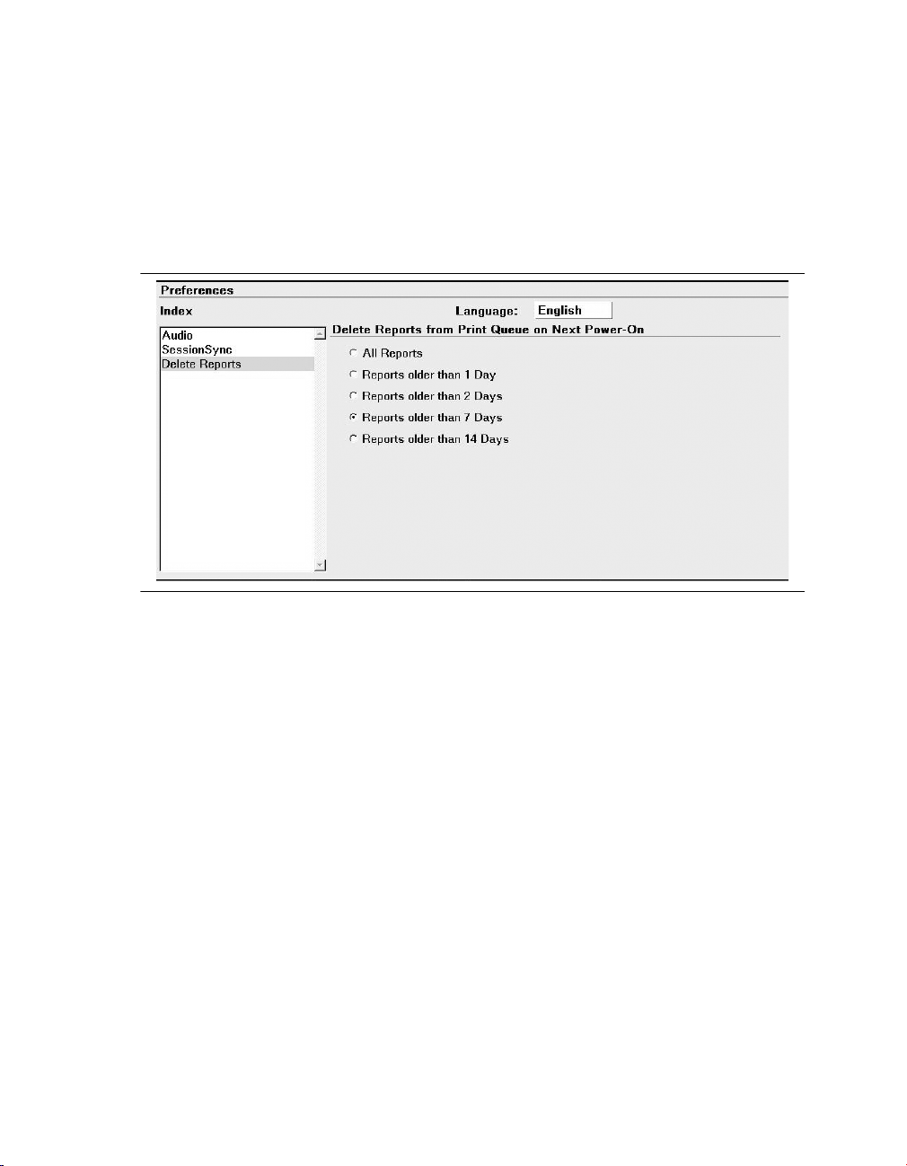
Medtronic MEDTRONIC CARELINK® 2090
6.7.1 Select a report deletion interval
1. Press the Programmer icon, and then select Preferences.
2. From the Preferences screen, select Delete Reports. The programmer displays the
Delete Reports screen as shown in Figure 22.
Figure 22. Delete Reports screen
3. Select a radio button to specify which reports the programmer deletes:
●
All Reports
●
Reports older than 1 Day
●
Reports older than 2 Days
●
Reports older than 7 Days (Default)
●
Reports older than 14 Days
The age of a report is determined by the date and time it was created. When the programmer
is powered on, reports that meet the deletion criteria are permanently deleted.
82 Reference Manual
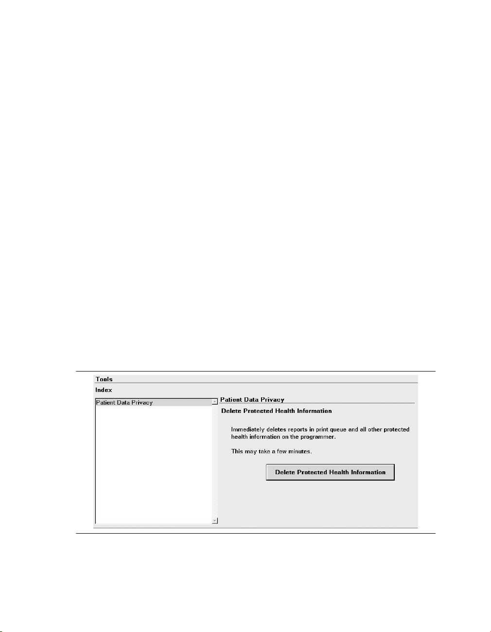
Medtronic MEDTRONIC CARELINK® 2090
6.7.2 Delete a report immediately
To delete a report immediately, directly access it from the print queue and press [Delete].
6.8 Manage patient data privacy
You can immediately remove from the programmer all Protected Health Information (PHI).
This feature deletes all of the following files:
●
Contents of the Print Queue (unless files are currently being printed or copied)
●
Temporary files residing on the programmer
●
Memory dumps (applies to Vitatron devices only)
You cannot delete any PHI data if a session is in progress or while files are being printed or
copied to media. If deletion is interrupted manually, some PHI remains on the programmer.
Note: The user of the programmer is responsible for the use of this feature, as well as for
management of patient data that has already been removed from the programmer (for
example on paper, diskette, or a USB flash drive).
6.8.1 Delete Protected Health Information
1. Press the Programmer icon, and then select Tools. The programmer displays the
Tools screen as shown in Figure 23.
Figure 23. Tools screen with Patient Data Privacy index item selected
Reference Manual 83
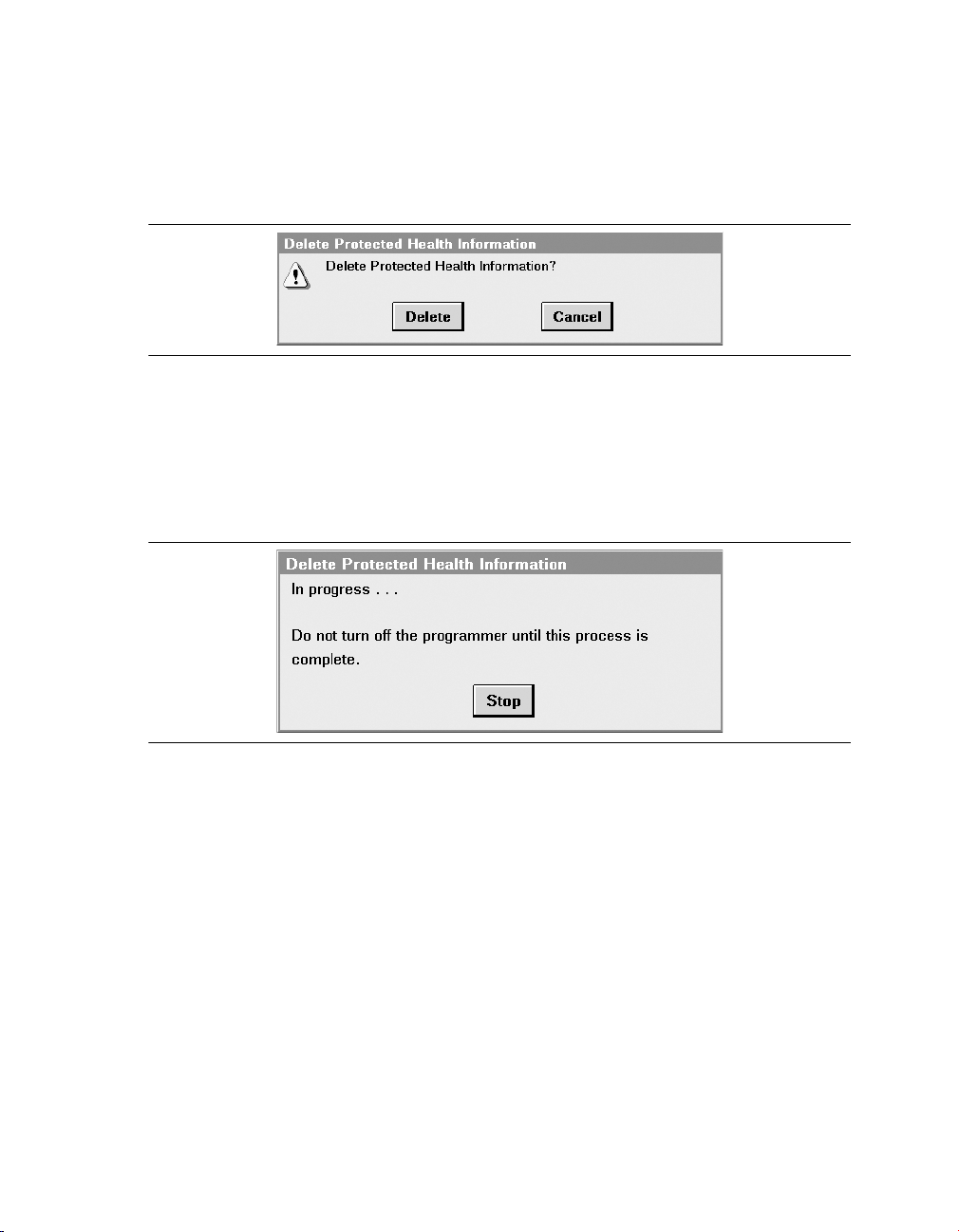
Medtronic MEDTRONIC CARELINK® 2090
2. Press [Delete Protected Health Information]. The programmer displays the dialog box
as shown in Figure 24.
Figure 24. Delete Protected Health Information confirmation dialog box
3. Press [Delete] to continue.
One of the following events may occur:
The programmer displays an “In progress…” dialog box as shown in Figure 25. Deletion
may last several minutes, depending on the amount of data to delete.
Figure 25. In progress dialog box
Note: On the In progress dialog box, press [Stop] if you want to halt further deletion. For
example, you may want to end a deletion process that is taking too long.
If you press [Stop], some protected health information remains on the programmer.
Or,
If there are reports currently printing, the programmer displays a message directing you
to wait until printing is complete, as shown in Figure 26. Press [Close].
84 Reference Manual

Medtronic MEDTRONIC CARELINK® 2090
Figure 26. Printing in progress dialog box
4. If pressing [Delete] in Step 3 resulted in protected health information deletion, the
programmer displays a message stating that deletion was successful, as shown in
Figure 27. Press [Close].
Figure 27. Deletion successful dialog box
Or,
If the programmer is unable to complete deletion of files, it displays a message stating
that there was an error and that some data may remain on the programmer, as shown in
Figure 28. Press [Close]. Contact Medtronic Technical Support if the message recurs.
Figure 28. Error deleting files dialog box
Reference Manual 85

Medtronic MEDTRONIC CARELINK® 2090
6.9 Vitatron Manual-Guided Reset
Manual-guided reset is a diskette-based tool that allows recovery of Vitatron DDD3, DIVA,
and (Co)DEMA devices that have lost data such as losing trim values on a device reset.
Before attempting to use the MGR diskette, ensure that no USB flash drives are connected.
86 Reference Manual
Medtronic MEDTRONIC CARELINK® 2090
7 RemoteView™ Programmer Consultation
7.1 About RemoteView
Medtronic RemoteView provides the ability for a programmer user to share the programmer
screen with a remote viewer, located in a different physical location anywhere in the world via
the Internet. RemoteView uses software on both the programmer and the remote viewer’s
system. The programmer user and remote viewer each establish a network connection to a
Medtronic RemoteView server. After the server provides authentication, screen sharing
occurs.
Notes:
●
RemoteView does not allow remote programming or remote control of the programmer;
it is only for viewing.
●
Also, patient data may be viewed on the remote system during a RemoteView
connection. For a review of potential data privacy issues, see Section 7.4.
7.2 RemoteView status icon
The RemoteView status icon on the programmer provides information about the connection
between the programmer and the remote system. The icon changes to indicate the
connection status between the programmer and the remote system.
Table 5. RemoteView status icon states
RemoteView status icon state Color What the icon indicates
Grayed out
(not selectable)
Gray RemoteView is available but not connec-
RemoteView is disabled. Clicking the
icon will cause the programmer to beep.
RemoteView is not available because
the device application is not supported or
you have a programmer that does not
meet the hardware system requirements. If your programmer does not
meet the hardware system requirements, contact Medtronic Technical
Support.
ted. There is no connection between the
programmer and the remote system.
Reference Manual 87
Medtronic MEDTRONIC CARELINK® 2090
Table 5. RemoteView status icon states (continued)
RemoteView status icon state Color What the icon indicates
Gray with
flashing
green
Green A successful connection has been
Gray with redXThe connection attempt has failed. You
The connection is being established
between the programmer and the remote
system, but it is not yet connected.
established between the programmer
and the remote system.
can attempt to reconnect by clicking the
icon again. Any of the following conditions may cause a connection attempt to
fail:
Network card error
Network cable connection error. Check
to see if the network cable is connected.
No internet access. Check with clinic network support staff to ensure HTTPS on
port 443 is allowed to connect to the
Internet.
Incorrect server configuration selected.
The server on the programmer and the
remote viewer’s system need to match.
See Section 7.3.1 for more specific information related to the Medtronic servers.
Invalid session key entered. Try to
re-enter the session key.
7.3 Use RemoteView
To use RemoteView, the programmer needs to be connected to your clinic’s network. Before
you begin, make sure your network is configured correctly.
Note: The remote viewer must have the appropriate remote viewing software installed to use
RemoteView.
7.3.1 Configure RemoteView network
The programmer user needs to configure the RemoteView Network the first time the
RemoteView Network is used by selecting the correct geographic designation as follows:
●
United States and World–choose this designation if the programmer user is physically
located in the United States or anywhere else in the world except for Europe, as defined
below.
88 Reference Manual

Medtronic MEDTRONIC CARELINK® 2090
●
Europe–choose this designation if the programmer user is physically located in Europe.
●
“Europe” means: Austria, Belgium, Bulgaria, Cyprus, Czech Republic, Denmark,
Estonia, Finland, France, Germany, Greece, Hungary, Ireland, Italy, Latvia,
Liechtenstein, Lithuania, Luxembourg, Malta, Netherlands, Norway, Poland, Portugal,
Romania, Slovakia, Slovenia, Spain, Sweden, Switzerland, or the United Kingdom.
1. Press the Programmer icon, and then select RemoteView Network
Configuration….
2. From the RemoteView Network Configuration screen, select the available field to
display the geographic designation options.
3. Select either “United States and World” or “Europe”, depending on your location.
4. Press [OK].
7.3.1.1 Server locations
These geographical designations correspond to the location of the Medtronic server,
through which the connection between the programmer user and the remote viewer is
established. The server corresponding to the “United States and World” designation is
located in the United States. The server corresponding to the “Europe” designation is
located in a Western European country.
7.3.1.2 Match programmer to the remote viewer’s system
When installing the remote viewing software, the remote viewer must select the
geographical location that matches the designation chosen by the programmer user. For
example, if the programmer user has chosen “Europe,” the remote viewer must also have
chosen “Europe” when installing the remote viewing software, regardless of the remote
viewer’s physical location. In this example, if the remote viewer has initially chosen “United
States and World,” the remote viewer will need to download a second copy of the remote
viewing software and choose “Europe” during this subsequent installation.
7.3.2 Enter RemoteView session key
A RemoteView session key is used by the remote viewer’s server to authenticate the
connection with the programmer user. At the start of each session, the remote viewer will
generate the session key on the remote user’s system and then share it with the programmer
user by telephone. Programmer users use the following steps:
Reference Manual 89

Medtronic MEDTRONIC CARELINK® 2090
1. Call the remote user to start the consultation conversation and obtain the session key.
2. Press the RemoteView icon on the programmer task bar.
3. Enter the 7-digit session key generated by the remote system using the number keys
and press [Enter].
7.3.3 End RemoteView connection
A RemoteView connection can be ended by either the programmer user or the remote viewer
using one of the following methods:
●
The programmer user ends a device application session and presses [End Session] on
the programmer screen. An active RemoteView connection will automatically terminate
when the application software is exited.
●
The programmer user presses the RemoteView icon when RemoteView is connected to
terminate a RemoteView connection.
●
The remote viewer clicks the “X” in the upper right corner of the connection window and
clicks End Session.
When the connection has ended, the RemoteView icon on the programmer task bar will
change from the green, connected state back to the gray, not connected state. The
programmer screen image will be blank for the remote viewer.
7.4 Data privacy
Patient data may be viewed on the remote system during a RemoteView session. Medtronic
provides the software on the programmer as well as the connectivity via a Medtronic server,
which enables this to occur. Medtronic does not, however, collect, use, or retain any patient’s
personal or health data via RemoteView.
The programmer user is responsible for complying with all applicable data privacy and data
protection laws and regulations when choosing to allow a remote viewer to view the patient
data via RemoteView, including obtaining consents and other agreements that may be
required. Allowing the viewing of patient data by a remote viewer in another country could
constitute a data transfer under the laws where the programmer user is located. For this
purpose, please see Section 7.3.1 for the RemoteView server locations.
90 Reference Manual

Medtronic MEDTRONIC CARELINK® 2090
8 SessionSync (Optional)
8.1 About SessionSync
SessionSync is an optionally installed feature that provides network connectivity between
the programmer and the Medtronic Paceart data management system. Using your clinic’s
network, the programmer can send downloaded device data and reports through
SessionSync to the data management system. Reports are only sent to Paceart systems
that accept them.
The SessionSync status icon and the SessionSync status screen provide information on the
connection status of the programmer to the data management system.
You must configure the programmer network settings to allow for this data transfer.
8.2 Configure SessionSync
8.2.1 Configure the SessionSync network connection
Before you begin, make sure your network is configured correctly.
1. Press the Programmer icon, and then select SessionSync Network
Configuration….
2. Enter the Clinic Name.
3. Enter the SessionSync network configuration information.
Note: If you do not have your SessionSync network configuration information, contact
your clinic’s technical support or Medtronic Technical Support.
4. Press [OK].
Reference Manual 91

Medtronic MEDTRONIC CARELINK® 2090
Figure 29. SessionSync Network Configuration
8.3 Enable and disable SessionSync
1. Select Programmer > Preferences.
2. Select SessionSync from the Index menu.
3. Select [Enabled] to enable SessionSync or Select [Disabled] to disable SessionSync.
Note: The SessionSync icon in the task bar will be grayed out when the feature is disabled.
SessionSync functions are not available within a patient session unless you have enabled
this feature prior to starting a patient session.
92 Reference Manual

Medtronic MEDTRONIC CARELINK® 2090
Figure 30. Preferences screen with Session Sync selected
8.4 SessionSync Status icon
The SessionSync status icon provides information on the network connection between the
programmer and the data management system.
Figure 31. The task bar with the SessionSync Status icon
1 The SessionSync Status icon
If SessionSync is not installed on the programmer, the icon is not visible in the task bar.
Figure 32. Parts of the SessionSync Status icon
1 The data management system status
2 The connection status between the programmer and the data management system
3 The programmer status
Reference Manual 93

Medtronic MEDTRONIC CARELINK® 2090
The sections of the SessionSync Status icon change colors to indicate data ready for
transfer, a valid connection between the programmer and the data management system,
and successful data transfer to the data management system.
Note: When the whole icon is grayed out, SessionSync has been disabled under the
programmer preferences.
Table 6. SessionSync Status icon states
Part of SessionSync Status Icon Color What the color indicates
Programmer Gray No session data files are in the Transfer
Queue.
Note: The transfer queue is the list of
session data files that have been saved
to the programmer hard disk but are waiting for transfer.
Blue Session data files exist in the Transfer
Queue
Connection Not visible No valid connection exists between the
programmer and the data management
system
Green Valid connection exists between the pro-
Red circle
with a line
through it
Data Management System Gray No session data has been transferred to
Blue All session data has been successfully
grammer and the data management system
Device application in use does not support SessionSync
the data management system
transferred to the data management system
8.5 Use Automatic SessionSync
Automatic SessionSync allows you to perform a SessionSync automatically at the end of a
patient session. This feature is available for all SessionSync enabled devices.
8.5.1 Create SessionSync Report(s) to send to Paceart
1. Press the Reports icon, and then select Print Queue.
2. Select SessionSync PDF printer from full-size printer menu.
94 Reference Manual

Medtronic MEDTRONIC CARELINK® 2090
Notes:
●
SessionSync PDF is not available in the Print Queue window on the desktop.
●
SessionSync PDF is available only if SessionSync is installed and enabled, and is only
availabe to SessionSync enabled device applications.
8.5.2 Save the patient session with Manual SessionSync
1. Press the Session icon.
2. Select SessionSync….
3. The SessionSync - Saving Session Data On Programmer window is opened and for
some devices an interrogation is automatically started. The SessionSync - Saving
Session Data On Programmer window shows the progress of the save. The
Programmer side of the SessionSync Status icon turns blue after the data has been
saved on the Programmer hard disk. If the subsequent transfer is successful, the data
management system side of the SessionSync Status icon turns blue.
4. Any reports that were printed using SessionSync PDF printer will be transmitted to
Paceart systems that accept them.
8.5.3 End a patient session with Automatic SessionSync enabled
1. Press [End Session…]. If an interrogation is required before the SessionSync data
transfer, the Interrogation Required window is displayed.
2. Verify that the Automatic SessionSync box is checked, and then press [End Now].
3. The SessionSync - Saving Session Data On Programmer window is opened. For some
devices, an interrogation is automatically started. The SessionSync - Saving Session
Data On Programmer window shows the progress of the save. The programmer side of
the SessionSync Status icon turns blue after the data has been saved on the
programmer hard disk. If the subsequent transfer is successful, the data management
system side of the SessionSync Status icon turns blue.
4. Any reports that were printed using SessionSync PDF printer will be transmitted to
Paceart systems that accept them.
8.6 Use Manual SessionSync for supported devices
Manual SessionSync allows you to send interrogated data to the Paceart data management
system without ending the patient session on the Programmer.
Reference Manual 95

Medtronic MEDTRONIC CARELINK® 2090
Manual SessionSync is not available for all SessionSync supported devices. If manual
SessionSync is available for a device, the SessionSync… option appears in the Session
menu.
8.7 SessionSync error message descriptions
You may receive error or information messages at different times in the SessionSync
process. For a list of error messages, see Table 7. If you have any issues with the
programmer contact Medtronic Technical Support at the telephone number on the back
cover of this manual.
Table 7. SessionSync error messages
Error Message What it means
Data Transfer Failed A device communication error has occurred during the interrog-
ation and you have cancelled out of the interrogation window. The
session data has not been saved on the programmer hard disk.
Do one of the following:
Press [Retry] to retry the operation.
Press [Cancel] to close the window.
Ending a Session without Automatic SessionSync
Interrogation Required You must conduct an interrogation before starting a SessionSync
Interrogate - Unsuccessful The programmer cannot interrogate the device. You must reposi-
Unable to Save Session Data The session data cannot be saved on the programmer hard disk.
You have cleared the Automatic SessionSync check box on the
End Session window before pressing the [End Now] button.
data transfer for this device.
Press [OK] to close the window.
tion the programming head.
Do one of the following:
Press [Retry] or [Continue] after repositioning the programming
head.
Press [Cancel] to close the window.
Do one of the following:
Press [Save to Media] or [Save Session] to save the session data
to media.
Press [End Now] to end the session without saving the device
data.
Press [Cancel] to close the window without saving the device
data.
96 Reference Manual

Medtronic MEDTRONIC CARELINK® 2090
8.8 View SessionSync Status screen
The SessionSync Status screen displays information on the data files being transferred to
the data management system using SessionSync. Each message includes the date, time,
and event information for the associated SessionSync event.
8.9 Update SessionSync status
1. Select Programmer > SessionSync Status.
2. Select [Update Status].
Note: SessionSync status does not dynamically update when the window is open. To
update, press the [Update Status] button.
8.10 Test the SessionSync network connection
Use the Test SessionSync feature when instructed to do so by Medtronic Technical Support,
or if your clinic’s network is having difficulty connecting to the SessionSync network. If the
SessionSync is enabled but no connection is made, clinic network support staff may wish to
use results of the network connection tests to troubleshoot the connection. Contact
Medtronic Technical Support if you need assistance in interpreting results.
Reference Manual 97
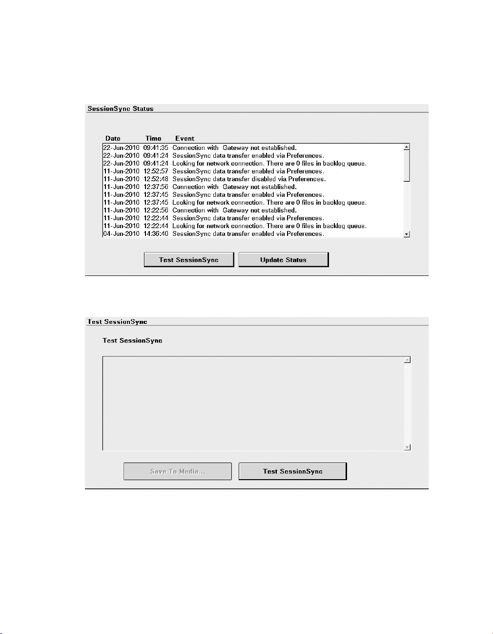
Medtronic MEDTRONIC CARELINK® 2090
8.10.1 Run the tests
1. Select Programmer > SessionSync Status.
2. Press [Test SessionSync].
The programmer displays the Test SessionSync dialog.
98 Reference Manual
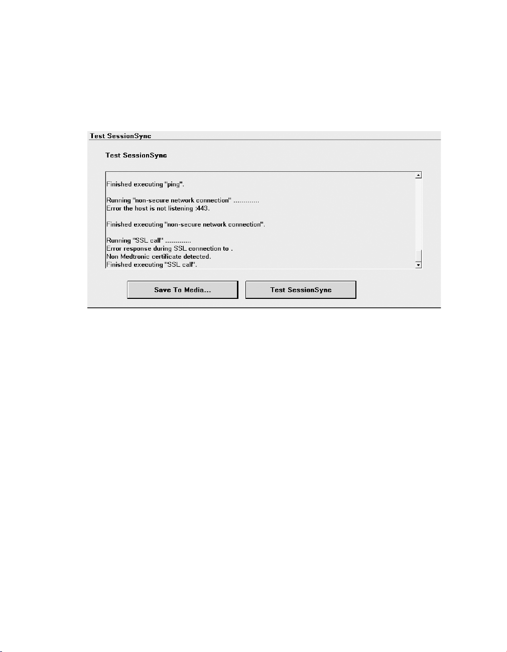
Medtronic MEDTRONIC CARELINK® 2090
3. Press [Test SessionSync].
Several diagnostic tests are run, and their results are listed on the dialog. The tests
include ipconfig command, nslookup command, tracert command, ping command,
and telnet command.
After tests are complete, the programmer screen displays “Finished executing SSL
call”.
8.10.2 Save network connection test results to media
1. Insert a diskette or connect a USB flash drive to the programmer.
2. On the Test SessionSync dialog, press [Save To Media].
Note: This button is available only if the Test SessionSync tests have been run.
The programmer displays the Save to Media dialog.
3. Press [Save].
A text file (ntwk_debug.log) containing the test results is saved to the diskette or USB flash
drive. Download the file to a compatible computer for viewing and/or transfer to Medtronic
personnel.
Reference Manual 99

Medtronic MEDTRONIC CARELINK® 2090
9 Service the programmer
9.1 Clean the system components
The exterior surfaces of the programmer and its accessories may be cleaned with a sponge
or soft cloth moistened with water, mild detergent, hydrogen peroxide, or alcohol.
Thoroughly clean the surfaces of the programmer wires; the bottom surface of the
programming head; and the wire connecting the programming head to the programmer.
Caution: Take care to prevent liquid from entering the programmer and programming head.
Do not immerse the programmer or any accessories in any liquid or clean them with aromatic
or chlorinated hydrocarbons.
The lead wires may be cleaned by wiping each lead wire with a sponge or soft cloth
moistened with the cleaning material, then wiped with a sponge or soft cloth moistened with
clean water, and then wiped dry.
The exterior surfaces of the lead wires can be cleaned up to 15 times with each of the
following materials without functional degradation:
●
Green soap, green soap tincture, or alcohol-free hand soap
●
2% gluteraldehyde solution (such as Cidex)
●
Sodium hypochlorite (bleach solution 10% in water)
9.2 Sterilize the programming head, ECG cable, and lead wires
Except for the programming head or ECG cable and lead wires, the programmer and its
accessories cannot be sterilized.
Caution: Do not autoclave the programming head or ECG cable and lead wires.
Visually inspect the cable and connections of the programming head after sterilizing. Do not
use the programming head if it appears damaged. Damage includes, but is not limited to,
deterioration of the cable insulation (brittleness, cracking, thinning, or bare spots). Do not
use the programming head if the conductive wires are exposed.
100 Reference Manual
 Loading...