

Page 1

User’s Guide
REF
Integrated Power Console (IPC™) System
1898001
Page 2

Symbols
EUR · USA · JPN · AUS
IPX1
EC REP
IPX7
ACC
IPX8
DEHP
STERILE
NIM
Accessory
REF
LOT
SN
REFURBISHED
!USA
On/O Button Package Contents Follow
EMC Compliance
Mark
Instructions For
Use
Do Not Oil Do Not Immerse
105345
Conforms to ANSI/AAMI ES60601-1,
Certied to CAN/CSA-C22.2 No.60601-1,
IEC/EN 60601-1
Caution: Federal law (USA) restricts this device
to sale by or on the order of a physician.
>120 VAC
ON
<120s
Fuse
Use By Date
Accessory
AC Power Type BF Applied Part Foot Pedal
Output Start/Stop Fine Irrigant
Is Approximately
Equal To
Non-Sterile Consult Instructions
Non-Sterile
Quantity
Not Greater Than
120vac
Caution
Applied Part
OFF
Duty Cycle
>180s
Catalog Number Manufacturer
Lot Number
Serial Number Ergonomically
XX° C
>X° C
BUR
EHS
Fr
Protected Against
Vertical Water Drops
Protected Against
The Eects Of
Temporary
Immersion In Water
Protected Against
The Eects Of
Temporary
Immersion In Water
RF Transmitter
(Interference May
Occur)
for Use
Stim Bur Connector
NIM Console
Connector
Electrical High
Speed Handpiece
Connector
World Wide Standard
for Medical Tubing
Diameter
Date of Manufacture Handpiece
<XX° C
Temperature
XX° C
Limitation
Outer Limits =
Transport
Inner Limits = Use
Engineered
F
R
1
2
Oscillate
Forward
Reverse
Connector
Adjustment
Left Foot Control
Unit Button /
Mode Button
Right Foot
Control Unit
Button / Control
Button
Top Foot Control
Unit Button
/ Handpiece
Button
Locked
Unlocked
Pump Head 1
Pump Head 2
Refurbished
Authorized Representative in the European
Community
Precaution: Pinch Hazard. Keep Fingers Clear
Of Rollers
PHT
Contains DEHP (di-2-ethyl hexyl phthalate)
Protective Earth
Equipotential Ground Connector
Use With
RoHS - Environmental friendly use period China (SJ/T11364-2006)
Do Not Dispose Of This Product In The
Unsorted Municipal Waste Stream. Dispose Of
This Product According to Local Regulations.
See
Recycling.Medtronic.com for Instructions On
Proper Disposal Of This Product.
If the single use symbol is on the device
label then this device is designed for single
patient use only. Do not reuse, reprocess, or
resterilize this product. Reuse, reprocessing, or
resterilization may compromise the structural
integrity of the device and/or create a risk of
contamination of the device, which could result
in patient injury, illness, or death.
Adapter
Attachment
Bone Mill
Brush
Control Unit
Dissecting Tool
Instrument Case
Lubricant/Diuser
Motor
Multi-Use Disposable Attachment
Regulator
USA Only Speed Range
<NNNN
min
For use up to
“NNNN” RPM
Page 3

Table of Contents
Symbols .......................................................................................................................................................... 2
IPC™ System .................................................................................................................................................... 4
Glossary ............................................................................................................................................................................................................................... 4
Indications for use ...........................................................................................................................................................................................................4
Device description ........................................................................................................................................................................................................... 4
Contraindications ............................................................................................................................................................................................................4
Additional IPC™ congurations ..................................................................................................................................................................................4
Warnings .............................................................................................................................................................................................................................4
Precautions .........................................................................................................................................................................................................................6
System requirements and specications ................................................................................................................................................................6
System sounds ..................................................................................................................................................................................................................7
System gures ...................................................................................................................................................................................................................8
Pre-and Post-operating instructions ...................................................................................................................................................................... 11
IPC™ components ......................................................................................................................................................................................................... 13
Guidance and Manufacturer’s Declaration – Electromagnetic Immunity ............................................................................................... 15
Limited warranty ........................................................................................................................................................................................................... 17
For items contaminated with TSE agents ............................................................................................................................................................ 17
Endo-Scrub™ 2 .............................................................................................................................................. 18
StraightShot™ M5, StraightShot™ M4, StraightShot™ Magnum™ II, and StraightShot™ III .................... 21
Skeeter™ Ultra-Lite Oto-Tool ....................................................................................................................... 26
Indigo™ High-Speed Otologic Drill ............................................................................................................. 28
Visao™ High-Speed Drill ............................................................................................................................... 32
Troubleshooting ........................................................................................................................................... 35
Error codes .................................................................................................................................................... 37
Cleaning and sterilization ............................................................................................................................ 39
Reprocessing Instructions - Endo-Scrub™ 2 Finger Switch ........................................................................................................................... 40
Reprocessing Instructions - StraightShot™ M5, StraightShot™ M4, StraightShot™ Magnum™ II, StraightShot™ III .................. 41
Reprocessing Instructions - Skeeter™ Oto-Flex Burs ........................................................................................................................................ 43
Reprocessing Instructions - Skeeter™ Handpiece ............................................................................................................................................. 44
Reprocessing Instructions - Indigo™ High-Speed Otologic Drill ................................................................................................................. 45
Reprocessing Instructions - Indigo™ High-Speed Otologic Drill Attachments ...................................................................................... 46
Reprocessing Instructions - Visao™ Handpiece .................................................................................................................................................. 47
Reprocessing Instructions - Frontal Sinus 2mm Mini Trephine Drill ........................................................................................................... 48
Reprocessing Instructions - Medtronic Burs ....................................................................................................................................................... 49
Customer service .......................................................................................................................................... 50
Integrated Power Console (IPC™) System
Page 4

IPC™ SYSTEM
IPC™ System
Glossary
The following words and acronyms may be used in this guide.
FCU Foot Control Unit
FWD Forward - Rotation is clockwise
I.V. Intravenous
IPC™ Integrated Power Console
NIM™ Nerve Integrity Monitor - One or all of the Nerve Integrity Monitor units: NIM-Response™ 2.0, NIM-Neuro™ 2.0, NIM-
Response™ 3.0 and NIM-Neuro™ 3.0
NIM-Eclipse™ Nerve Integrity Monitor for spinal surgeries
OSC Oscillate
REV Reverse - Rotation is counter-clockwise
XPS Xomed Power System
Tool Surgical cutting device
Motor Handpiece/drill
Accessory Any compatible product that can be used with the IPC™
Attachment Any compatible product that can be secured to a handpiece
Indications for use
The IPC™ System is indicated for the incision/cutting, removal, drilling and sawing of soft and hard tissue and bone in Head & Neck/ENT
(Otologic, Neurologic, Neurotologic, Sinus, Rhinologic, Nasopharyngeal/Laryngeal), Oral/Maxillofacial and Plastic/Reconstructive/Aesthetic
surgical procedures.
Device description
The IPC™ System is a powered microdebrider, drill and saw system that will remove soft tissue, hard tissue and bone during surgical procedures.
The system consists of a power control console, foot pedal, connection cables and assorted handpieces to drive various burs, blades, drills, rasps,
cannulae and saws. It includes integrated irrigation pumps for irrigation of blades, burs and for motor coolant.
In addition to the handpieces and pumps there is a connection for continuous stimulation of the Visao™ straight burs that enables nerve
integrity monitoring during surgical procedures. The Nerve Integrity Monitor (NIM™) is a separate device that stimulates and monitors the nerve.
This system has connections that allow the NIM™ to be connected with the Visao™ handpiece and stimulating bur guard, enabling the NIM™ to
stimulate and monitor the nerve at the surgical site.
This device is intended for use by physicians trained in the procedures described.
Contraindications
None.
Additional IPC™ congurations
Additional IPC™ congurations are available. Refer to the following User’s Guides for related information.
• IPC™ POWEREASE™ System Model: 2340000 (IPC™ User’s Guide)
• Neurosurgical IPC™ System Model: EC300 (IPC™ User’s Guide CFN 175027)
Consult the appropriate User’s Guide for indications, contraindications, warnings, and component information specic to each system.
Warnings
System warnings
W1 It is important that the IPC™ system operator be familiar with the system User’s Guide, its precautions, procedures and safety issues.
W2 Do not use the IPC™ system in the presence of ammable anesthetics. Avoid potential ignition or explosion of gases.
W3 To avoid the risk of electric shock, this equipment must only be connected to a supply main with protective earth.
W4 To avoid the risk of electrical shock, achieve electrical grounding reliability with proper connections. Connect the IPC™ system to hospital
grade receptacles only.
W5 Do not attach any system component or accessory other than Medtronic approved components to the IPC™ system as this may result in
electrical shock, component damage, substandard performance, increased emissions, or decreased immunity.
1-4
Integrated Power Console (IPC™) System
Page 5

IPC™ SYSTEM
W6 Disconnect power to the IPC™ system before cleaning the unit to avoid electrical shock.
W7 This medical device complies with EN60601-1-2 safety standard for electromagnetic compatibility, requirements and test. However, if this
equipment is operated in the presence of high levels of electromagnetic interference (EMI) or highly sensitive equipment, interference may
be encountered and the user should take whatever steps are necessary to eliminate or reduce the source of the interference. Diminished
performance may lengthen operating time for the anesthetized patient.
W8 Do not operate the IPC™ system in the presence of Magnetic Resonance Imaging devices.
W9 Medical Electrical Equipment needs special Precautions regarding EMC and needs to be installed and put into service according to the EMC
information provided in this User’s Guide.
W10 The IPC™ system should not be used adjacent to or stacked with other equipment. If adjacent or stacked use is necessary, the IPC™ system
should be observed to verify normal operation in the conguration in which it will be used.
W11 Portable and mobile RF communications equipment can aect Medical Electrical Equipment.
W12 Keep NIM™ Muting Probe cable away from IPC™ system cables to prevent unintended EMG interference or muting.
W13 After each procedure, properly clean all reusable system components.
W14 All service must be performed by Medtronic qualied personnel only. Repair and/or modication to the IPC™ system by anyone other than
qualied service personnel may signicantly compromise the unit’s ability to perform eectively and/or void the equipment warranty.
W15 Auxiliary Power Outlet with protective cover is for use with the Hydrodebrider or Bone Mill only. Consult Hydrodebrider and Bone Mill
instructions prior to use.
Component Warnings
W16 Always inspect the components before and after use for any damage or malfunction. If damage or malfunction is observed, do not use
damaged part until it is repaired or replaced. Use of damaged or malfunctioning parts can increase risk of injury.
W17 Motors and attachments may fail due to extended use and allow a component to detach and fall from the motor or attachment, causing
patient injury.
W18 Do not use an overheated device as it may cause thermal injury. Smoke and/or excessive heat may be caused by:
• Applying excessive force while cutting (e.g. side loading)
• Long operating periods (exceeding handpiece duty cycle)
• Attachment not fully locked in handpiece
• Inadequate or loss of irrigation
• Component failure or wear
W19 The handpieces will not run properly unless the attachment is in the locked or secured position.
W20 Do not change accessory with handpiece running to prevent laceration of user and cross-contamination through compromised glove.
W21 Do not place motor, attachment and tool on the patient or in an unsecured location during surgery.
W22 Do not activate foot pedal without conrming the safe position and handling of the handpiece. Accidental handpiece activation could
result in unintended tissue, bone, or nerve resection.
W23 Verify reusable device was cleaned and sterilized prior to use. If not sterilized, do not use.
W24 For warnings & precautions related to reprocessing, refer to Cleaning and sterilization instructions.
W25 This system requires insulated connectors for the StraightShot™ M4 Microdebrider, StraightShot™ Magnum™ II Microdebrider,
StraightShot™ III Microdebrider, Midas Rex™ Spine Shaver (SC1), Visao™, or Skeeter™ handpieces and the multifunction foot pedal.
W26 When using StraightShot™ microdebrider handpieces with non-rotatable tools, ensure rotation lock is engaged to prevent inadvertent
rotation. When using with optical Image Guided Surgery (IGS), engage the rotation lock prior to calibration and verication of the tip.
Disposable Warnings
W27 Tools are available for resection of soft tissue and bone for surgical procedures. Use of tools depends on the intended application and
patient needs. Sharp cutting powered tools induce bleeding and removal of signicant tissue and bone.
W28 Do not use accessory if package is opened or damaged. Broken seal oers no protection against cross-contamination.
W29 Operate the tool only after the appropriate anatomical landmarks and the intended surgical site have been conrmed. Ensure adequate
visualization when using powered accessories. Discontinue powered application in the event of lack of visualization of the surgical site.
W30 Use methods at the operative site to control bleeding that do not compromise patient safety during at-risk surgery.
W31 Always keep the cutting area of the tool away from ngers and loose clothing to prevent laceration of user and cross-contamination
through compromised glove.
W32 Excessive noise from the tool when drilling close to the cochlea or ossicular chain may cause hearing damage.
W33 Improper use of high speed burs can result in damage to the eye and/or orbit, vascular damage, nerve damage, and/or cerebral damage.
Use appropriate caution when operating this device in the vicinity of critical anatomy.
W34 Excessive pressure applied to tool may cause tool fracture. Should a tool fracture in use, extreme care must be exercised to ensure that all
fragments of the tool are retrieved and removed from the patient. Unremoved tool fragments may cause tissue damage to the patient.
W35 Do not use excessive force to pry or push bone with the attachment, tool or blade during dissection.
W36 Do not apply excessive side loading. Excessive side loading could cause angled attachments to unlock accidentally from motor.
Integrated Power Console (IPC™) System
1-5
Page 6

IPC™ SYSTEM
W37 Do not modify any system components or accessories. Use of modied components or accessories may increase risk of injury or diminish
performance of the system.
W38 Insertion of metal objects in accessory tip may cause the accessory to break leaving fragments in the wound. The fragments may be
dicult to remove, causing irritation, inammation and foreign-body response at surgical site.
W39 Bending or prying may break the accessory, causing harm to patient or sta.
W40 Inspect tools prior to and during use for signs of wear, fragmentation, eccentricities, or other defects. Replace and discard damaged tools.
Do not attempt to re-sharpen tools.
W41 Test attachments for excessive vibration at desired speed before use. Vibration may be caused by eccentricity of the tool or worn
components. Replace tool, attachment, or handpiece, or change handpiece speed.
W42 Test for wobble at desired speed prior to use. Discontinue use of accessory if tip begins to wobble and replace accessory to prevent
unintended tissue removal from patient.
W43 Powered blades should be operated in the Oscillate mode only. Operating in the Forward mode may cause damage to the blade.
W44 Do not use the burs above the speed indicated on the bur label.
W45 If an airway blade becomes clogged during use, 1-5 cc of irrigant could be aspirated by the patient before detection by the user.
W46 Do not attempt to sterilize disposable devices. The disposables are packed sterile and are intended for single use. Devices lose sterility
upon removal from packaging.
Precautions
P1 Do not kink cables. Inspect cables and pins for cracks, tears or corrosion.
P2 When using a Y-Splitter, only one multifunction foot pedal shall be active at a time.
P3 Do not connect multiple Y-Splitters.
P4 StraightShot™ handpieces are intended to operate at speeds greater than 6,000 rpm only when used with the high speed bur line.
P5 Do not use anti-fog on scope or sheath, as weeping or leaking may result.
P6 Do not use excessive force to insert the endoscope into the Endo-Scrub™ 2 sheath. this will damage the endoscope as well as the Endo-
Scrub™ 2 sheath.
P7 If the endoscope tip can be seen extending beyond the tip of the Endo-Scrub™ 2 sheath, then the sheath has been damaged. Damaged
product must be immediately discarded.
P8 Remove and discard accessories following local regulations for proper disposal of contaminated materials.
P9 When using an angled attachment, hold the handpiece assembly by the attachment so that the attachment does not inadvertently loosen
from the handpiece.
P10 Always examine operation of each tool in a handpiece before use.
P11 Powered burs and drills should be operated in the Forward mode only.
P12 To prevent damage to tools, disconnect suction tube prior to changing tool during procedure.
P13 Ensure the blade or bur is fully engaged in the microdebrider. For blades, verify the tip is fully engaged with the outer cannula prior to use.
P14 T&A blades: Gently remove the inner tube from the outer tube. The inner tube may elongate upon removal from the outer tube. If this
occurs, the inner tube may not lock properly into the handpiece or the blade may not work properly.
P15 T&A blades: Rotate the inner tube when removing and inserting it in the outer tubes to prevent damage to the internal seal. If the seal is
damaged, the blade will leak at the handpiece.
System requirements and specications
Console Specications
Functional Standards for Electrical Systems
ANSI/AAMI ES60601-1 Medical electrical equipment - Part 1: General requirements for basic safety and essential
performance
IEC 60601-1 Medical electrical equipment - Part 1: General requirements for basic safety and essential
performance
EN 60601-1 Medical electrical equipment - Part 1: General requirements for basic safety and essential
performance
IEC 60601-1-4 Medical electrical equipment - Part 1: General Requirements for Safety, Part 4: Programmable
Electrical Medical Systems
IEC 60601-1-2 Medical electrical equipment - Part 1-2: General Requirements for Safety - Collateral Standard:
Electromagnetic Compatibility - Requirements and Tests
CAN/CSA C22.2 #60601-1 Medical Electrical Equipment - Part 1: General Requirements for basic safety and essential
performance
1-6
Integrated Power Console (IPC™) System
2005, 2012
2005, 2012
2006, 2014
1996, 1999
2007, 2014
2005, 2014
Page 7

Physical Dimensions
Size 277 mm Width x 353 mm Height x 267 mm Depth
Weight 7.3 kg
Operational Environment
Temperature +10 °C to +33 °C
Humidity 30 % to 75 % RH
Barometric Pressure 700 - 1060 hPa
Transport and Storage Environment
Temperature -40 °C to +70 °C
Humidity 10 % to 95 % RH
Barometric Pressure 500 to 1060 hPa
Display / Touchscreen
Type High contrast, digital, graphic color, visible in complete darkness
Resolution Display 21 cm diagonal, resolution 480 X 640 pixels
Audio Output
Baseline Audio Sound Level 60 dBA minimum SPL (1 m)
Electrical
Input Voltage 100 V-240 V ± 10%
Frequency 50/60 Hz
Power Consumption 500 VA
Auxiliary AC output 200 VA Max.
Internal Fuse 5 x 20 mm T. L. 5 A, 250 V
Medtronic Xomed P/N 11270066
Duty Cycle for Applied Part Maximum On Time 120 Seconds
Minimum O Time 180 Seconds
IPC™ SYSTEM
System power cords
Region Part Number Region Part Number Region Part Number
USA, Barbados, Belize,
Bolivia, Canada,
Colombia, Ecuador,
Venezuela
Standard
EA600 or 1895820
6 meter
EA650 or 1897821
United Kingdom,
Ireland, Hong Kong,
Malaysia, Singapore
EA606 Austria, Belgium, Finland,
France, Germany, Greece,
Korea, Luxembourg,
Netherlands, Norway,
Portugal, Spain, Sweden
EA602 or 1895822
China EA604 India, South Africa EA607 Switzerland EA601
Argentina EA608 Israel EA609 Denmark EA610
Australia, New Zealand EA605 Japan EA603 or 1895823 Italy, Chile EA611
System sounds
The following tones can sound while using the IPC™ Console.
IPC™ Tone Cause(s)
1 Tone • Conrmation of change button pressed.
• Change from Forward to Oscillate.
• Change of active handpiece.
2 Tones Change from Oscillate to Forward.
3 Tones • Audible Alarm. Error detected. See screen for error message.
• Active handpiece is in Reverse and foot pedal pressed.
• First time accessory changes from Forward to Reverse.
Long Tone Change from handpiece to drill.
Integrated Power Console (IPC™) System
1-7
Page 8
IPC™ SYSTEM
12
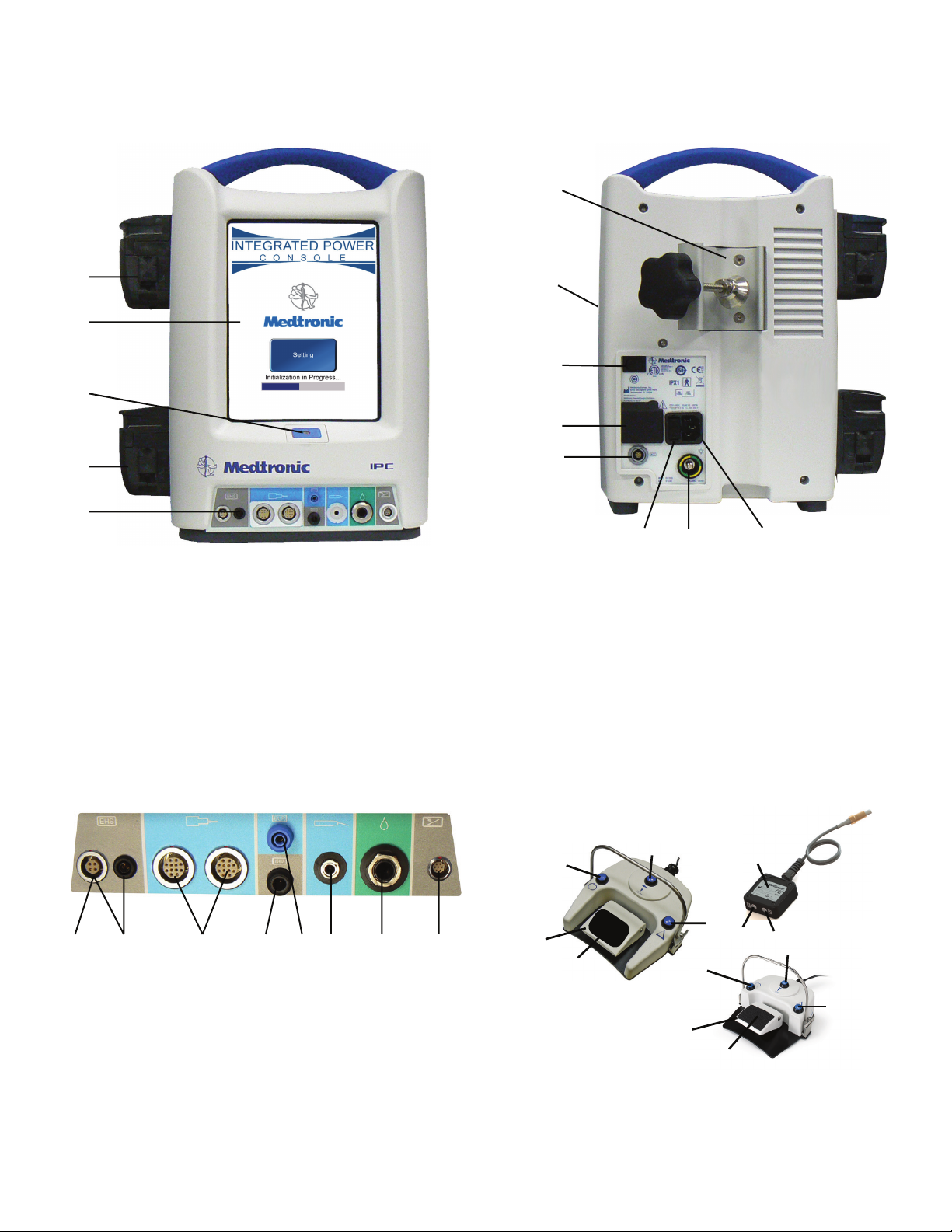
System gures
Figure 1-1. IPC™ Console Front
1
2
3
4
5
1 Pump 1: Coolant, lens cleaning or irrigation
2 Touchscreen
3 Power on/o
4 Pump 2: Irrigation or lens cleaning
5 Console connector panel for peripheral devices
Figure 1-2. IPC™ Console Back
1
2
3
4
5
67 8
1 Pole clamp
2 Compact ash card port (Medtronic Use)
3 Manual start/stop
4 Auxiliary power outlet
5 Endo-Scrub™ 2 connector
6 Fuse access
7 Equipotential Ground Connector.
Apply potential equalization conductor.
8 Hospital grade power cord connector
1 Not applicable 4 Stimulus input from patient interface
2 Not applicable 5 Stimulus output to stim bur guard or
3 StraightShot™ M5 microdebrider,
StraightShot™ M4 microdebrider,
StraightShot™ Magnum™ II
microdebrider, StraightShot™ III
microdebrider, Visao™ drill, Indigo™
drill
1-8
Figure 1-3. IPC™ Console Connector Panel
3567 8
4
(NIM™ or NIM-Eclipse™)
POWEREASE™
6 Skeeter™ handpiece
7 Endo-Scrub™ 2 nger switch, Endo-
Scrub™ 2 foot pedal, IntelliFlow™
irrigation remote control
8 Multifunction foot pedal
Figure 1-4. Multifunction Foot Pedal & Y-Splitter
1
5
4
2
3
1
5
1 Mode button 5 Foot pedal
2 Handpiece button 6 Y-Splitter
3 Control button 7 Port 1
4 Slip-resistant foot pad 8 Port 2
6
7
8
2
4
Integrated Power Console (IPC™) System
3
Page 9

IPC™ SYSTEM
Figure 1-5. IPC™ Touchscreen
1
Speed
2
3
4
5
1 Displays active handpiece 5 Opens Help screen
2 Accessory control panel 6 Irrigation accessory panel
3 Foot pedal variable control 7 Inactive handpiece
4 Opens Pumps screen 8 Set active handpiece settings as default
Acceleration
Pump 2
Pumps
?
?
Help
Handpiece Name
+
60000
100
+
+
%
+
+
0
cc/min
EndoScrub 2
Flow
+
RPM
Prime
(Handpiece Name)
Setting
Finger
3
Control
+
+
Mode
FWD
REV
Foot
Both
PrimeOn
Figure 1-6. IPC™ Pumps Screen
Prime
Pump 1
None
None
3
Pump 2
8
None
7
6
4
1 Close Pumps screen 3 Pump 1 panel available accessories
2 Prime/Flush pump 4 Pump 2 panel available accessories
None
M4
M4
Irrigation
Irrigation
Prime
Endo-Scrub® 2
Endo-Scrub® 2
Prime
Endo-Scrub® 2
Endo-Scrub® 2
1
2
Figure 1-7. Operating Room Setup
3
2
1
10
4
9
7
8
1 Mode anesthesia equipment 6 Microscope
2 IPC™ system 7 Surgeon
3 Nursing supplies/Surgical
instruments
4 Scrub nurse 9 Anesthesiologist
5 NIM™ Monitor 10 Patient
Integrated Power Console (IPC™) System
8 Electro-Surgical unit
5
6
1-9
Page 10

IPC™ SYSTEM
Figure 1-8. IPC™ System Conguration
1
Figure 1-9. IntelliFlow™ Remote Control
1
2
2
3
11
3
4
10
9
5
6
8
7
1 Irrigation and coolant bags 7 Irrigation pole base diameter
2 Irrigation pole 8 Irrigation pole basket
3 IPC™ console 9 Power cord
4 Console connector panel 10 Pump 2
5 Accessory cables 11 Pump 1
6 Console height
1 Pause/On-O
2 Increase/Decrease Fine Adjustment
3 Increase/Decrease Coarse Adjustment OR
Select stainless steel tubing size (French size) for suction
irrigator.
1-10
Integrated Power Console (IPC™) System
Page 11

IPC™ SYSTEM
Pre-and Post-operating instructions
The following are general IPC™ pre- and post-operating instructions. Refer to other sections of this IFU for operating instructions specic to
individual handpieces or accessories.
When the system arrives
• Verify the contents of the box match the packing slip. If incomplete or damaged, notify Medtronic Customer Service.
• If container is damaged, or cushioning material shows stress, notify carrier and Medtronic Customer Service. Keep shipping materials for
carrier inspection.
• Save the cartons and packing material. If the instrument is to be shipped the shipping package will provide proper protection.
Set up the IPC™
Refer the related topics for detailed instruction.
1. Install pump cartridges or irrigation tubing.
2. Prepare IPC™ for use.
3. Calibrate touchscreen, if necessary.
4. Change system settings, if necessary.
5. Set up and prime pumps.
6. Conrm system operation.
7. Press the manual start/stop button on the back of the console (Figure 1-2) and verify you can start/stop the handpiece, irrigation and/or
coolant ow.
Install the pump cartridges or irrigation tubing
1. Locate the correct pump and lift up the lock (Figure 1-10).
Pump 1: Coolant, lens cleaning or irrigation
Pump 2: Irrigation
Note: The number on the pump must match the number on the cartridge (either 1/1
or 2/2). If the cartridge does not have a pump designator number, use the Pump Setup
Screen to install the pump cartridge.
2. Insert the pump cartridge.
3. Snap the pump lock shut.
Note: Ensure the pump cartridge does not crimp the tubing.
Figure 1-10. Install Pump Cartridge
1
2
3
Prepare IPC™ for use
1. Verify Operation Room set up (Figure 1-7). The surgeon may have preferences to the location and visibility.
2. Verify the wheels are locked on the IPC™ cart.
3. Inspect all components for damage and determine if the system is ready for use.
4. Mount the IPC™ and irrigation/coolant bags on the I.V. pole (Figure 1-8).
Notes:
• Mount irrigant and coolant bags above the IPC™ to ensure adequate ow.
• It is recommended to use an irrigation pole with minimum base diameter of 53 cm and to mount all items as low as possible to increase
stability during use.
• For transport or uneven oor conditions greater than 10 degrees, maximum height to mount the console is 38 cm if irrigation and coolant
bags are at fully extended pole height.
5. Plug the IPC™ into the power source. Position the IPC™ so that it does not obstruct the power source for the purpose of disconnecting the
Main voltage by the power cord.
6. Locate the correct foot pedal or accessory connection port on the connector panel (Figure 1-3), align the mark on the connector to the mark
on the console, and then insert the connector.
7. Connect suction, cooling and/or irrigation tubing.
8. Turn on the IPC™ and verify the system passes the self-test and the accessory screen appears on the IPC™ monitor.
Note: If the IPC™ does not detect a handpiece or foot pedal the Connect Handpiece/Connect Foot Switch screen appears. Do the following:
• Verify the cable is connected to the correct connection port.
• Press [OK] in the Connect Handpiece/Connect Foot Switch message window to continue use of the IPC™ without the handpiece or foot
pedal.
Calibrate touchscreen
Note: This step is optional.
1. Turn on the IPC™ console.
2. When the system starts, on the Splash screen, press [Settings].
3. On the Settings screen, press Touch Screen Calibration and follow the screen prompts.
Integrated Power Console (IPC™) System
1-11
Page 12

IPC™ SYSTEM
Change system settings
Note: During surgery, system settings can be overwritten.
1. Turn on the IPC™ console.
2. While the system starts, on the Splash screen, press [Settings].
3. To change the language, press the appropriate language.
4. To change the default settings, press [Default].
• On the Default screen, press the Forward or Backward arrow to change the accessory.
• Make changes to the default settings.
• To conrm system settings and return to the Splash screen, press [OK].
5. For accessories with audible tones, press the REV Audible Tones button to control the following:
• The system delivers one set of reverse beeps when the Reverse mode is activated.
• The system delivers one set of reverse beeps the rst time the drill is used in Reverse mode after the Reverse mode has been activated.
6. To conrm system settings and continue to the IPC™ touchscreen, press [OK].
7. To restore settings to factory default, press [Restore].
Handpiece default settings
The system conguration is dependent on the handpiece(s) connected to the console. The following table denes the default congurations,
default settings (X) and default options (O).
Note: During use, update the default settings for the active handpiece by pressing the Set active handpiece settings as default settings
button (Figure 1-5).
Table 1. IPC™ Touchscreen Default Congurations
Speed Mode or Mode Select Switch
Handpiece rpm cpm % Forward Oscillate Reverse Acceleration Deceleration Size Flow Irrigation Control
Visao™ 80000 X O 30
Indigo™ 52000 X O 30
StraightShot™ M5 5000 O X 05
StraightShot™ M4 5000 O X 05
StraightShot™ III, Magnum™ II 5000 O X 30
Skeeter™ 16000 X O v 0
Endo-Scrub™ 2 3
Suction Irrigator 8 50 %
Set up and prime pumps
• The IPC™ turns on pump 1 and/or 2 long enough to purge air out of the tubing set(s) the rst time the prime button is pressed.
• The IPC™ resets the prime feature when you turn IPC™ power O and On.
• After you prime the pump, the prime button and functionality become ush functionality.
1. Connect tubing from an IPC™ cartridge to irrigation or coolant port on an accessory.
2. On the irrigation tubing, turn the clamp to OPEN.
3. If an accessory uses the clear drip chamber (Visao™), ll the clear drip chamber with coolant. To ll, squeeze and release the chamber until
full.
4. On the IPC™ touchscreen (Figure 1-5), press the pumps button.
Note: The IPC™ pumps screen is also available from the Connect Handpiece/Connect Foot Switch screen which the system displays during
IPC™ preparation for use if a handpiece or foot switch is not detected by the system.
5. On the IPC™ pumps screen (Figure 1-6), select the accessory for each pump.
6. For each pump, press the prime button and verify the following:
• Pump(s) run until air is completely purged from tubing.
• Small amount of lubricant ows at the tip of the irrigation device.
• Pump(s) turns o.
7. Press the close button.
1-12
Integrated Power Console (IPC™) System
Page 13

IPC™ SYSTEM
+
Pump default congurations
The pump conguration is dependent on the handpiece(s) connected to the console. The following table denes the pump default settings (X)
and default options (O).
Table 2. IPC™ Pumps Screen Default Congurations
Pump 1 Pump 2 Endo-Scrub™ 2 Suction Irrigator
Handpiece Cooling Irrigation Irrigation Pump 1 Pump 2 Pump 1 Pump 2
Visao™ X X O O
Indigo™ O X O O O O
StraightShot™ M5 O X* X O
StraightShot™ M4 O X* X O
StraightShot™ III, Magum II O X* X O
Skeeter™ O O O O
Endo-Scrub™ 2 X O X O
Suction Irrigator O O O O
* When the IPC™ detects both the StraightShot™ M4 or StraightShot™ M5 and the Legend EHS Stylus Touch handpiece, by default, the system sets
pump 2 as a “shared” irrigation pump. You must manually connect the irrigation tubing to the active handpiece.
Conrm system operation
1. Conrm the irrigation pedal starts handpiece and irrigation ow. Verify the speed changes from white to yellow in the Speed box on the
touchscreen.
2. Conrm the foot pedal buttons operate. Refer to Multifunction foot pedal for details.
3. On the touchscreen, verify you can do all of the following:
• Adjust Speed: In the Speed box, press the plus and minus buttons.
• Change Modes: In a Mode box, press any mode button.
• Adjust Flow Rate: In the Irrigation box, press the plus and minus buttons.
+
+
+
Disassemble the IPC™
1. Remove irrigation tubing or cartridge from IPC™ pump.
Note: Before removing the tubing from the pump, adjust the clamp on the intravenous tubing to the CLOSED position to prevent excessive
drainage of irrigant from the intravenous bag.
2. Disconnect components and cables. To disconnect non-silicone multi-pin cables from the console, push the cable toward the console and
then pull out by the lock ring.
Note: Silicone insulated multi-pin and single pin cable connectors do not have a lock ring. Remove these types of cable connectors straight
from the connector panel.
3. After disconnecting insulated connectors from the console, connectors that have debris under the insulator must be cleaned according to
Cleaning and Sterilization instructions. If debris is still present after cleaning and sterilization, return for warranty servicing.
4. See Cleaning and sterilization section of this User’s Guide for instructions.
IPC™ components
Auxiliary power to console
• The auxiliary power outlet is available for use with the Hydrodebrider™ and Bone Mill consoles only.
• The auxiliary power outlet is for use at grid voltage ≤120 VAC only.
Multifunction foot pedal
You can use the multifunction foot pedal (Figure 1-4) to start/stop the handpiece, control handpiece speed, handpiece selection and mode of
operation. Refer to the Multifunction foot pedal controls topic for each handpiece for specic use and control.
Y-Splitter
Y-Splitter (Figure 1-4) allows using a maximum of two multifunction foot pedals connected to a single IPC™. In this conguration, the Y-Splitter
shall be connected to the IPC™, and the multifunction foot pedal(s) shall be connected to the Y-Splitter. When connecting a single foot pedal to
the Y-Splitter, you may connect to either Port 1 or 2.
Integrated Power Console (IPC™) System
1-13
Page 14

IPC™ SYSTEM
IntelliFlow™ irrigation remote control
Use the IntelliFlow™ irrigation remote control (Figure 1-9) to start/stop and change irrigation ow while in the sterile eld.
If you are using handpiece irrigation:
• To pause irrigation ow, press the Pause/On-O button.
• To adjust ow rate, press the Fine Adjustment or Coarse Adjustment Increase/Decrease button.
If you are using the Suction Irrigator:
• To pause or turn on/o the Suction Irrigator, press the Pause/On-O button.
• To adjust ow rate, press the Fine Adjustment Increase/Decrease button.
• To select the stainless steel tubing size (French size), press the Stainless Steel Tubing Size button.
1-14
Integrated Power Console (IPC™) System
Page 15

IPC™ SYSTEM
Electromagnetic compatability
Environment of Intended Use: Professional healthcare facility environment
Guidance and manufacturer’s declaration – electromagnetic emissions
The IPC™ System is intended for use in the electromagnetic environment specied below. The customer or the user of the IPC™ System should assure that it is used in such an
environment.
Emissions test Compliance Electromagnetic environment - guidance
RF emissions
CISPR 11
RF emissions
CISPR 11
Harmonic
emissions
IEC 61000-3-2
Voltage
uctuations/icker
emissions
IEC 6100-3-3
The IPC™ System is intended for use in the electromagnetic environment specied below. The customer or the user of the IPC™ System should assure that it is used in such an
environment.
Immunity test IEC 60601-1-2 test level Compliance level Elec tromagnetic environment - guidance
Electrostatic
discharge (ESD) IEC
61000-4-2
Electrical fast
transient/burst
IEC 61000-4-4
Surge
IEC 61000-4-5
Voltage dips, short
interruptions and
voltage variations
on power supply
input lines
IEC 61000-4-11
Power frequency
(50/60 Hz)
magnetic eld
IEC 61000-4-8
NOTES:
1. UT is the mains voltage prior to application of the test level.
2. When the console is powered and connected to the footswtich, application of -15KV air discharge onto the footswitch buttons may cause the console to freeze. Power cycle the
console to re-establish normal operation.
Group 1 The IPC™ System uses RF energy only for its internal function. Therefore, its RF emissions are very low and are not likely to cause
Class A The IPC™ Systems suitable for use in all establishments, ther than domestic and those directly connected to the public low-
Class A
Complies
any interference in nearby electronic equipment.
voltage power supply network that supplies buildings used for domestic purposes.
Guidance and manufacturer’s declaration – electromagnetic immunities - part I
± 8 kV contact
± 15 kV air
± 2 kV for power supply lines
± 1 kV for input/output lines
± 1 kV line to line
± 2 kV line to earth
0% UT (100% dip in UT)
for 0.5 cycle at 0°, 45°, 90°, 135°,
180°, 225°, 270°, and 315°
0% UT (100% dip in UT)
for 1 cycle at 0°
40% UT (60% dip in UT) for
5 cycles
70% UT (30% dip in UT) for 0.5 sec
0% UT (100% dip in UT) for 5 sec
30 A/m 30 A/m Power frequency magnetic elds should be at levels characteristic of a typical location
± 8 kV contact
± 15 kV air
± 2 kV for power supply lines
± 1 kV for input/output lines
± 1 kV line to line
± 2 kV line to earth
0% UT (100% dip in UT)
for 0.5 cycle at 0°, 45°, 90°, 135°,
180°, 225°, 270°, and 315°
0% UT (100% dip in UT)
for 1 cycle at 0°
40% UT (60% dip in UT) for
5 cycles
70% UT (30% dip in UT) for 0.5 sec
0% UT (100% dip in UT) for 5 sec
The relative humidity should be at least 5% Note-1.
Mains power quality should be that of a typical commercial or hospital environment.
Mains power quality should be that of a typical commercial or hospital environment.
Mains power quality should be that of a typical commercial or hospital environment.
If the user of the IPC™ System requires continued operation during power mains
interruptions, it is recommended that the IPC™ System be powered from an
uninterruptible power supply or a battery.
in a typical commercial or hospital environment.
Integrated Power Console (IPC™) System
1-15
Page 16

IPC™ SYSTEM
Guidance and manufacturer’s declaration – electromagnetic immunities - part II
The IPC™ System is intended for use in the electromagnetic environment specied below. The customer or the user of the IPC™ System should assure that it is used in such an
environment.
Immunity test IEC 60601-1-2 test
Conducted RF
IEC 61000-4-6
Radiated RF
IEC 61000-4-3
NOTE: These guidelines may not apply in all situations. Electromagnetic propagation is aected by absorption and reection from structures, objects and people.
level
3 Vrms
150 kHz to 80 MHz
6 Vrms
150 kHz to 80 MHz
in ISM bands and
amateur radio bands
3 V/m
80 MHz to 2.7 GHz
9–28 V/m
Spot frequencies
385 MHz–5.785 GHz
Pulse modulation
Compliance level Electromagnetic environment - guidance
3 Vrms
150 kHz to 80 MHz
6 Vrms
150 kHz to 80 MHz
in ISM bands and
amateur radio bands
3 V/m
80 MHz to 2.7 GHz
9–28 V/m
Spot frequencies
385 MHz–5.785 GHz
Pulse modulation
Portable RF communications equipment (including peripherals such as antenna cables and external antennas)
should be used no closer than 30cm (12 inches) to any part of the IPC™ System, including cables specied by
the manufacturer. Othewise, degradation of the performance of this equipment may result.
Portable and mobile RF communications equipment should be used no closer to any part of the IPC™ System
including cables, than the recommended separation distance calculated from the equation applicable to the
frequency of the transmitter.
Recommended separation distance
where P is the maximum output power rating of the transmitter in watts (W) according to the transmitter
manufacturer, E is the immunity test levels in volt per meter (V/m), and d is the recommended separation
distance in meters (m).
Interference may occur in the vicinity of equipment marked with the following symbol:
d = (6/E) √P
Recommended separation distances between
portable and mobile RF communications equipment and the IPC™ System
The IPC™ System is intended for use in an electromagnetic environment in which radiated RF disturbances are controlled. The customer or the user of the IPC™ System can help prevent
electromagnetic interference by maintaining a minimum distance between portable and mobile RF communications equipment (transmitters) and the IPC™ System as recommended
below, according to the maximum output power of the communications equipment.
Rated
maximum
output
power of
transmitter
P(W)
0.01 0.03 0.03 0.07 0.03 0.03 0.03 0.07
0.1 0.07 0.07 0.21 0.07 0.07 0.07 0.21
1 0.22 0.22 0.67 0.22 0.22 0.22 0.67
10 0.7 0.7 2.12 0.7 0.7 0.7 2.12
100 2.2 2.2 6.7 2.2 2.2 2.2 6.7
For transmitters rated at a maximum output power not listed above, the recommended separation distance d in metres (m) can be determined using the equation applicable to the
frequency of the transmitter, where P is the maximum output power rating of the transmitter in watts (W) according to the transmitter manufacturer.
NOTE: These guidelines may not apply in all situations. Electromagnetic propagation is aected by absorption and reection from structures, objects and people.
380 MHz–390MHz
d = 0.22√P
430 MHz–470MHz
d = 0.22√P
Separation distance according to frequency of transmitter m
704 MHz–787MHz
d = 0.67√P
800 MHz–960MHz
d = 0.22√P
1.7 GHz–1.99GHz
d = 0.22√P
2.4 GHz–2.57GHz
d = 0.22√P
5.1 GHz–5.8GHz
d = 0.67√P
1-16
Integrated Power Console (IPC™) System
Page 17

IPC™ SYSTEM
Limited warranty
A. This Limited Warranty provides the following assurance for the customer who purchases a Medtronic IPC™ System. This Limited Warranty is
extended only to the buyer purchasing the IPC™ System directly from Medtronic or from its aliate or its authorized distributor or representative. The IPC™ System includes the console, motor or handpiece, foot control, motor cables, instrumentation cases and trays (hereafter referred
to as System Components), straight and angled motor attachments (hereinafter referred to as “Attachments”), bur guards and telescoping
tubes (hereinafter referred to as Semi-reusable Components) and dissecting tools, irrigation and coolant tubing, and Intelliow remote control
(hereinafter referred to as Single Use Components) and jointly referred to as the IPC™ System, unless specically noted.
i. Should a System Component fail to function to Medtronic’s published specications during the term of this Limited Warranty (one [1] year
from the date of sale of a new System Component or ninety [90] days from the date of sale of a refurbished or used System Component),
Medtronic will either repair or replace the Motor Component or any portion thereof.
ii. Should an Attachment fail to function to Medtronic’s published specications during the term of this Limited Warranty (ninety [90] days
from the date of sale of a new Attachment), Medtronic will either repair or replace the Attachment or any portion thereof.
iii. Should a Semi-reusable Component fail to function to Medtronic’s published specications during the term of this Limited Warranty (thirty
[30] days from the date of sale of a new Semi-reusable Component), Medtronic will replace the Semi-reusable Component or any portion
thereof.
iv. Should a Single Use Component fail to function to Medtronic’s published specications prior to its “use by” date Medtronic will replace the
Single Use Component.
B. To qualify for this Limited Warranty, the following conditions must be met:
i. The Product must be used on or before its “Use By” or “Use Before” date, if applicable.
ii. The Product must be used in accordance with its labeling and may not be altered or subjected to misuse, abuse, accident or improper
handling.
iii. Medtronic must be notied in writing within thirty (30) days following discovery of a defect.
iv. The Product must be returned to Medtronic within thirty (30) days of Medtronic receiving notice as provided for in (3) above.
v. Upon examination of the Product by Medtronic, Medtronic shall have determined that: (i) the Product was not repaired or altered by any-
one other than Medtronic or its authorized representative, (ii) the Product was not operated under conditions other than normal use, and
(iii) the prescribed periodic maintenance and services, if applicable, have been performed on the Product.
C. This Limited Warranty is limited to its express terms. THIS LIMITED WARRANTY IS IN LIEU OF ALL OTHER WARRANTIES, EXPRESSED OR IMPLIED
WHETHER STATUTORY OR OTHERWISE, INCLUDING ANY IMPLIED WARRANTY OF MERCHANTABILITY OR FITNESS FOR A PARTICULAR PURPOSE.
In no event shall Medtronic be liable for any consequential, incidental, prospective or other similar damage resulting from a defect, failure, or
malfunction of the IPC™ System, whether a claim for such damage is based upon the warranty, contract, negligence or otherwise.
D. The exclusions and limitations set out above are not intended to, and should not be construed so as to, contravene mandatory provisions of
applicable law. Users may benet from statutory warranty rights under legislation governing the sale of consumer goods. If any part or term of
this Limited Warranty is held by any court of competent jurisdiction to be illegal, unenforceable, or in conict with applicable law, the validity
of the remaining portion of the Limited Warranty shall not be aected, and all rights and obligations shall be construed and enforced as if this
Limited Warranty did not contain the particular part or term held to be invalid.
For items contaminated with TSE agents
Medtronic recommends incineration of devices that have directly or indirectly contacted patients suspected or conrmed with prions or a
Transmissible Spongiform Encephalopathy (TSE) such as Crutzfeldt-Jakob disease (CJD).
Integrated Power Console (IPC™) System
1-17
Page 18

ENDOSCRUB™ 2
(5)
Endo-Scrub™ 2
Device description
The system can be used to clear the end of a rigid rod endoscope in order to maintain good visualization of endoscopic procedures without
having to remove the scope from the surgical site.
Indications for use
The device is indicated for use during routine diagnostic procedures and during endoscopic sinus surgery with standard mechanical
instruments.
The IPC™ System incorporates Endo-Scrub™ 2 functionality by using irrigation pump number one (1) and controlling operation with the touch
screen and an external foot pedal or nger switch.
DO NOT use the Endo-Scrub™ 2 for infusion, for disinfection or sterilization of an endoscope, or for suction removal of blood and debris.
Use the Endo-Scrub™ 2 sheath only with an endoscope listed on the sheath product label, as malfunction or poor performance could result.
Figure 2-1. Endo-Scrub™ 2 Finger Switch Figure 2-2. Endo-Scrub™ 2 Foot Pedal
(1)
(2)
1 Finger switch 4 Light connection
2 Endo-Scrub™ 2 sheath 5 Finger Switch cable
3 Irrigation connection
(3)
(4)
Endo-Scrub™ 2 assembly
1. Inspect the endoscope to ensure that it is in good condition. Imperfections will prevent complete retraction of irrigant. The scope lens should
be free of ne pits, microcracks, or rough seals. The endoscope barrel should be free of mineral deposits or other encrustation.
2. Wet interior insertion port of the plastic sheath hub and outer surface of the endoscope shaft prior to assembly. Wetting both surfaces of
each item allows for easier positioning.
3. Slowly, slide the approved endoscope into the Endo-Scrub™ 2 sheath (Figure 2-3). The endoscope tip MUST NOT extend past the sheath end
as irrigation run-in will occur.
Note: Do not force the endoscope fully into the plastic hub. The sheath may be damaged beyond use if the endoscope is pushed fully into
the plastic hub.
4. Connect the irrigation tubing and a light source (Figure 2-4).
Figure 2-3. Endo-Scrub™ 2 Assembly Figure 2-4. Endo-Scrub™ 2 Assembly
Endo-Scrub™ 2 nger switch assembly
If using the Endo-Scrub™ 2 nger switch, complete the following:
1. Slide the nger switch onto the Endo-Scrub™ 2 sheath (Figure 4-1). Align the cutout section of the ring with the luer connector of the tubing
set. The nger switch is properly installed when the cutout section of the ring is rmly seated against the luer connector.
2. Activate the pump by pressing the actuator button located on the nger switch.
1-18
Integrated Power Console (IPC™) System
Page 19

ENDOSCRUB™ 2
Endo-Scrub™ 2 activation
1. To activate the Endo-Scrub™ 2 wash cycle, press and release the nger switch or multifunction foot pedal.
2. To initiate a continuous ow of irrigant, press and hold the nger switch or multifunction foot pedal.
Note: Do not use the Endo-Scrub™ 2 as a suction device. If blood or debris are suctioned into the sheath, it may be necessary to briskly ush
out the empty sheath by using a syringe lled with sterile normal saline solution.
Connect Endo-Scrub™ 2 to IPC™ console
1. Locate the Endo-Scrub™ 2 connector cover on the back of the IPC™ console (Figure 1-2).
2. Insert a small screwdriver in the notch on the cable connector cover and pull.
3. Connect the control switch cable to the cable connector.
4. Connect the Endo-Scrub™ 2 nger switch (Figure 2-1) or the multifunction foot pedal (Figure 2-2) to the console (Figure 2-5).
Endo-Scrub™ 2 touchscreen controls
To set or adjust Endo-Scrub™ 2 controls, on the IPC™ touchscreen, in the Flow section of the Endo-Scrub™ control box (Figure 2-6), do the
following:
• To enable the Endo-Scrub™ 2 , press the On/O check-box.
• To adjust the ow rate, press the plus button to increase ow rate or the minus button to decrease ow rate.
• To prime the pump, press the prime button.
Figure 2-5. IPC™ Endo-Scrub™ 2 Connection Port Figure 2-6. IPC™ Endo-Scrub™ 2 Touchscreen
(1)
1 Finger switch or foot pedal connection port
Endo-Scrub™ 2 in standalone mode
The Endo-Scrub™ 2 can operate as a standalone device by changing the IPC™ system defaults.
1. On the Defaults menu (Figure 2-7), in the Stand Alone section, select Endo-Scrub™ and then press [OK].
2. On the Handpiece Connection screen (Figure 2-8), in the Endo-Scrub™ box, press [OK].
Figure 2-7. IPC™ General System Default
Menu
Figure 2-8. Handpiece Connection Screen
Integrated Power Console (IPC™) System
1-19
Page 20

ENDOSCRUB™ 2
Endo-Scrub™ 2 cleaning and sterilization instructions
Refer to document 68E4005 in the Cleaning and Sterilization section.
Endo-Scrub™ 2 foot pedal cleaning
If debris is found under the foot pedal boot, return for warranty service.
Do not immerse or sterilize the foot pedal unit.
Do not use alcohol, other solvents or abrasive cleaners.
1. Wipe down the Endo-Scrub™ 2 foot pedal with a cloth dampened with a neutral enzymatic detergent, pH 6.0-8.0 or phenol based
disinfectant.
2. Dry the unit with a clean, non-abrasive cloth.
1-20
Integrated Power Console (IPC™) System
Page 21

STRAIGHTSHOT™ M5, STRAIGHTSHOT™ M4, STRAIGHTSHOT™ MAGNUM™ II, AND STRAIGHTSHOT™ III
12 3
2
StraightShot™ M5, StraightShot™ M4, StraightShot™ Magnum™ II, and StraightShot™ III
Device description
The StraightShot™ M5 Microdebrider handpiece is an accessory to the IPC™ system and uses a cannulated motor that provides a suction path
through the motor. The handpiece can operate at speeds of 30,000 rpm forward and 7500 rpm oscillate. The higher forward operating speeding
allows the handpiece to support high speed burs.
The StraightShot™ M4 Microdebrider, features a nger wheel that enables the user to rotate the cutting tip of specially designed straight and
curved rotatable blades. It is also compatible with non-rotating blades and burs. It includes a locking mechanism to prevent inadvertent rotation
of non-rotating blades. The lightweight design combines high power and precision performance and can operate in forward mode of 12000 rpm
for bur operation and 5000 rpm in oscillate for blade operation. The StraightShot™ M4 also provides irrigation tubing management grooves to
keep tubing out of the surgeon’s way during a procedure.
Note: The StraightShot™ III and the StraightShot™ Magnum™ II are not for sale in the United States.
The IPC™ incorporates the microdebrider at pump 2. Control operation of the microdebrider with the IPC™ touchscreen and the multifunction
foot pedal.
When the IPC™ detects both the StraightShot™ M4 or StraightShot™ M5 and the Legend EHS Stylus handpieces, the system defaults Pump 2 to
the Shared conguration. You must manually move the irrigation tubing from the inactive to the active handpiece. Use the pumps screen to
override the Shared default by selecting the StraightShot™ M4 or the Legend EHS Stylus for Pump 1. Refer to “Set up and Prime Pumps” for more
information.
Figure 3-1. StraightShot™ M5 Handpiece Figure 3-2. StraightShot™ Magnum™ II and III Handpiece
1
45
1 Finger wheel 4 Finger wheel lock 1 Suction barb 2 Locking collar
2 Irrigation tubing groove 5 Locking collar
3 Suction barb
StraightShot™ M4 and StraightShot™ M5 blade or bur assembly
1. Insert the tool aligning the tabs with the notches (Figure 3-3). Orientate the irrigation barb to the left or right side.
Note: The StraightShot™ M4 and the StraightShot™ M5 use a four-tab alignment system.
• For rotating straight blades, orient the irrigation barb at the 3 o’clock position for right-handed surgeons and 9 o’clock for left-handed
surgeons.
• For rotating curved blades, orient the irrigation barb at 3 o’clock.
• For rotatable blades, adjust the nger wheel with small back-and-forth motions until the blade is engaged.
2. Press the locking collar (Figure 3-4).
3. Release the locking collar.
Note: If the collar does not return to full out position adjust the nger wheel with small back-and-forth motions until collar pops out.
4. Pull on the blade or the bur to ensure engagement and visually check to make sure the distal tip of the inner blade is in contact with the
distal tip of the outer cannula (Figure 3-5).
Figure 3-3. Blade or Bur Assembly Figure 3-4. Blade or Bur Assembly Figure 3-5. Blade or Bur Assembly
Integrated Power Console (IPC™) System
1-21
Page 22

STRAIGHTSHOT™ M5, STRAIGHTSHOT™ M4, STRAIGHTSHOT™ MAGNUM™ II, AND STRAIGHTSHOT™ III
12
StraightShot™ M4 and StraightShot™ M5 suction and irrigation tube assembly
1. Attach a suction tube to the suction source and an irrigation tube on the irrigation barb (Figure 3-6).
2. Secure suction and irrigation in the irrigation groove on the handpiece (Figure 3-7).
Figure 3-6. Suction and Irrigation Assembly Figure 3-7. Suction and Irrigation Assembly
StraightShot™ Magnum™ II and StraightShot™ III blade and bur assembly
1. Press the collet and insert blade in collet (Figure 3-8).
2. Release the collet (Figure 3-8).
3. Pull on the tool to ensure engagement and check distal tip of inner blade is in contact with the distal tip of the outer cannula.
StraightShot™ Magnum™ II and StraightShot™ III suction and irrigation assembly
1. Attach a suction tube to the suction source and an irrigation tube on the irrigation barb (Figure 3-9).
2. Secure suction and irrigation tubing with tubing clips.
Figure 3-8. StraightShot™ II and III Blade and Bur Assembly Figure 3-9. StraightShot™ II and III Suction and Irrigation
Assembly
Connect StraightShot™ to IPC™ console
Locate the StraightShot™ connection port on the connector panel (Figure 3-10) and insert the connector.
Note: To insert multi-pin connectors (indicated by a silver or red mark on the connector), align the mark on the connector to the mark on the
console, then insert the connector.
Figure 3-10. IPC™ Connection Ports
1-22
1 Handpiece connection port
2 Multifunction foot pedal connection port
Integrated Power Console (IPC™) System
Page 23

STRAIGHTSHOT™ M5, STRAIGHTSHOT™ M4, STRAIGHTSHOT™ MAGNUM™ II, AND STRAIGHTSHOT™ III
StraightShot™ touchscreen controls
Note: The StraightShot™ Magnum™ II and StraightShot™ III handpiece screens feature the same controls as those shown on the StraightShot™
M4 touchscreen.
Note: When you stop the blade, one of the following occurs:
• If the IPC™ button is visible on the touchscreen, the inner blade returns to the same position it began.
• If the XPS button is visible on the touchscreen, the inner blade stops the current position.
To set or adjust StraightShot™ controls, on the IPC™ touchscreen, in the StraightShot™ Handpiece control box (Figure 3-11, 3-12), do the
following:
• To change rotation mode, select OSC (oscillating) or FWD (forward).
Note: The system displays the default Oscillating or Forward mode speed.
• To adjust speed for the StraightShot™ M4, StraightShot™ Magnum™ II, and StraightShot™ III, in the Speed control box, press the plus to
increase speed or the minus button to decrease speed.
Forward Mode: Default, 12000 rpm; variable adjustment from 50 to 12000 rpm.
Oscillate Mode: Default, 5000 rpm; variable adjustment from 50 to 5000 rpm.
• To adjust speed for the StraightShot™ M5, in the Speed control box, press the plus to increase speed or the minus button to decrease speed.
Forward Mode: Default, 12000 rpm; variable adjustment from 50 to 30000 rpm.
Oscillate Mode: Default, 5000 rpm; variable adjustment from 50 to 7500 rpm.
• To adjust the irrigation ow rate, in the Pump control box, press the plus button to increase ow rate or the minus button to decrease ow
rate. If intermittent ow is available, pressing the plus or minus button progresses the system through intermittent and continuous ow. The
system displays Intermittent when in intermittent ow mode.
Forward Mode: Default, 30 cc per minute.
Oscillate Mode: Default, 5 cc per minute.
Note: To adjust ow rate, you can use the touchscreen or the IntelliFlow Irrigation remote control.
• To rotate outer blade, use the nger wheel (Figure 3-1).
• In oscillating mode only, you can use the Blade Position control box to do any of the following:
Note: The motion indicator indicates rotation direction of the blade.
To enable the multifunction foot pedal to change rotation displacement, press the delta button.
To rotate inner blade in small increments, press the counter-clockwise buttons.
Figure 3-11. StraightShot™ M4 Touchscreen Figure 3-12. StraightShot™ M5 Touchscreen
Integrated Power Console (IPC™) System
1-23
Page 24

STRAIGHTSHOT™ M5, STRAIGHTSHOT™ M4, STRAIGHTSHOT™ MAGNUM™ II, AND STRAIGHTSHOT™ III
1
24
Microdebrider blade control
Note: Periodically submerse blade tip in sterile water, with suction on, to keep blades clear during the procedure.
• To rotate the outer blade (Figure 3-13), use the nger wheel (Figure 3-1).
• To rotate the inner blade, use the Blade Position control box on the IPC™ touchscreen. Refer to the related accessory Controls topic for further
information.
Multifunction foot pedal controls
By default, press each button on the foot pedal for at least 100 ms for the selection to become active. Use the IPC™ touch screen Settings screen
to change the default value.
To use the multifunction foot pedal (Figure 3-14) to control the handpiece do the following:
• To select forward or oscillate mode, press the mode button.
• To start or adjust the speed of a handpiece in variable mode, press the foot pedal.
• To rotate the inner blade (60 or 180), press the control button.
• To change the handpiece, press the handpiece button.
Figure 3-13. Blade Dissection Figure 3-14. Multifunction Foot Pedal & Y-Splitter
1
5
4
2
1
5
3
1 Suction ow in through inner blade irrigation ow between inner and outer blades 1 Mode button 5 Foot pedal
2 Outer blade 2 Handpiece button 6 Y-Splitter
3 Inner blade 3 Control button 7 Port 1
4 Outer sleeve 4 Slip-resistant food pad 8 Port 2
6
3
7
8
2
4
Cleaning and sterilization instructions
Refer to document 68E3282 in the Cleaning and Sterilization section.
StraightShot™ M4 technical specications
StraightShot™ M4 1898200T
Size 14.3 cm Length x 1.8 cm Width (1898200T)
Weight 228 g 1898200T
Speed 50-5000 rpm oscillate
50-12000 rpm forward
Duty Cycle for Applied Part The StraightShot™ M4 handpiece under full load is rated for intermittent operation per the following:
Maximum On Time: 60 seconds
Minimum O Time: 30 seconds
3
1-24
Integrated Power Console (IPC™) System
Page 25

STRAIGHTSHOT™ M5, STRAIGHTSHOT™ M4, STRAIGHTSHOT™ MAGNUM™ II, AND STRAIGHTSHOT™ III
StraightShot™ M5 technical specications
StraightShot™ M5 1899200
Size 12.5 cm Length x 2.0 cm Width (1899200)
Weight 203 g 1899200
Speed 50-7500 rpm oscillate
50-30000 rpm forward
Duty Cycle for Applied Part The StraightShot™ M5 handpiece under full load is rated for intermittent operation per the following:
Maximum On Time: 60 seconds
Minimum O Time: 30 seconds
StraightShot™ Magnum™ II and StraightShot™ III technical specications
StraightShot™ Magnum™ II 1897200
StraightShot™ III 1897201
Size 17 cm Length x 1.6 cm Width (1897200/1897201)
Weight 240 g 1897200, 1897201
254 g 1897200T
Speed 50-5000 rpm oscillate
50-12000 rpm forward
Duty Cycle for Applied Part Under full load is rated for intermittent operation per the following:
Maximum On Time: 60 seconds
Minimum O Time: 30 seconds
Integrated Power Console (IPC™) System
1-25
Page 26

SKEETER™ ULTRALITE OTOTOOL
4
Skeeter™ Ultra-Lite Oto-Tool
Device description
The Skeeter™ handpiece and burs may be used with the IPC™ via direct connection with the Skeeter™ handpiece connector. The lightweight
Skeeter™ Ultra-Lite Oto-Tool Handpiece weighs 57 grams. The drill shaft diameter is approximately 2mm and is angled approximately 15 degrees
from the plane of the handpiece. The shaft angulation and small diameter maximize visualization of the surgical eld during drill use.
The Skeeter™ is used with the Oto-Flex bur. The Oto-Flex bur, designed for use with the Skeeter™, are composed of a exible stainless steel shaft
with a bur and a PTFE bearing at one end, and the handpiece engagement at the other. The inside of the PTFE bearing is lightly coated with
silicone spray to reduce operating friction.
Oto-Flex bur color coding
For identication of size, all Oto-Flex Burs are color coded. Diamond burs are further dierentiated from carbide burs by a white band on the
shaft of each diamond bur. A color code chart is provided in the base of the Oto-Tool System sterilization case. The bur size identication color
codes are as follows:
Color Bur Size Color Bur Size Color Bur Size
Violet 0.5 mm Yellow 0.8 mm Brown 1.8 mm
Blue 0.6 mm Orange 1.0 mm Red 2.3 mm
Green 0.7 mm Gray 1.4 mm Black Specialty
Skeeter™ assembly
1. Press the bur release button (Figure 4-1).
2. Load the desired bur for the procedure into the handpiece by inserting the bur shaft through the distal end of the handpiece with a slight
twisting motion while simultaneously pressing the bur release button.
3. The bur is locked into place when a “click” is noted. Locking of the bur should be checked prior to use by rmly pulling on the bur after the
“click” is noted.
4. Tug the bur to ensure it ts securely in the handpiece.
5. To remove the bur from the handpiece, press the bur release button on the handpiece and pull the bur out.
Connect Skeeter™ to IPC™ console
On the IPC™ Console, locate the Skeeter™ accessory connection port on the connector panel (Figure 4-2), align the mark on the connector to the
mark on the console, then insert the connector.
The Skeeter™ does not use irrigation. By default, the system sets both pumps to None.
Control the operation of the Skeeter™ with the IPC™ touchscreen and the multifunction foot pedal.
Figure 4-1. Skeeter™ Handpiece Assembly Figure 4-2. IPC™ Connection Port
3
2
1
(1) (2)
5
1 Bur at distal end 4 Bur shaft 1 Skeeter™ handpiece connection port
2 Bur color code 5 Bur release button 2 Multifunction foot pedal connection port
3 PTFE bearing
1-26
Integrated Power Console (IPC™) System
Page 27

SKEETER™ ULTRALITE OTOTOOL
Skeeter™ touchscreen controls
To set or adjust Skeeter™ controls, on the IPC™ touchscreen, in the Skeeter™ control box (Figure 4-3), do the following:
• To change rotation mode, in the Mode control box, select FWD (forward) or REV (reverse).
• To adjust speed, in the Speed control box, press the plus button to increase speed or the minus button to decrease speed.
Default, 16000 rpm; variable adjustment from 1000 to 16000 rpm.
Skeeter™ multifunction foot pedal controls
By default, press each button on the foot pedal for at least 100 ms for the selection to become active. Use the IPC™ touch screen Settings screen
to change the default value.
To use the multifunction foot pedal (Figure 4-4) to control the handpiece do the following:
• To select Forward or Reverse mode, press the mode button.
• To start or adjust the speed of a handpiece in variable mode, press the foot pedal.
• To toggle between the start/stop mode and variable speed mode, press the control button.
• To change the handpiece, press the handpiece button.
Figure 4-3. Skeeter™ Touchscreen Figure 4-4. Multifunction Foot pedal and Y-Splitter
Skeeter
Speed
16000
RPM
+
+
Mode
FWD
REV
1
5
4
2
1
6
3
7
8
2
1 Mode button 5 Foot pedal
2 Handpiece button 6 Y-Splitter
3 Control button 7 Port 1
4 Slip-resistant food pad 8 Port 2
Skeeter™ cleaning and sterilization instructions
Refer to documents 68E3968 and 68E3969 in the Cleaning and Sterilization section.
Skeeter™ technical specications
Skeeter™ 3055601
Size 17 cm Length x 1.6 cm Diameter
Weight 57 g
Speed 1000-16000 rpm forward/reverse
Duty Cycle for Applied Part Continuous run
Storage Temperature -40 C to +70 C
Humidity 10 % to 100 % RH
Barometric Pressure 500 to 1060 hPa
3
5
4
Integrated Power Console (IPC™) System
1-27
Page 28

INDIGO™ HIGHSPEED OTOLOGIC DRILL
1 Correct Alignment
Indigo™ High-Speed Otologic Drill
Device description
The Indigo™ High-speed Otologic drill is a small, compact high-speed, high-torque, reversible electric drill that can be used to dissect bone and
biomaterial at variable speeds from 200 to 60000 rpm. The cable cannot be removed from the drill.
The Indigo™ drill is designed to work only with Medtronic burs and Indigo™ attachments. The use of other burs and attachments may result in
sub-standard performance and will void the manufacturer’s warranty.
Indigo™ drill straight attachment assembly
1. Verify the alignment marks on the motor collet are in alignment (Figure 6-1).
Note: If the marks are misaligned, turn the collet until the marks are aligned.
2. Slide the attachment over the motor collet (Figure 6-2) so that the alignment mark on the attachment aligns with the alignment mark
(unlocked symbol) on the motor collet.
3. Insert the bur with a slight twisting motion until you feel it seat into position.
4. Turn the attachment so the alignment mark aligns with the locked symbol on the motor collet. You will hear two clicks while rotating the
attachment.
5. To ensure a secure t, gently pull the tool.
Note: The Indigo™ motor will not run correctly unless the attachment is in the locked position.
Indigo™ drill angled attachment assembly
1. Verify the alignment marks on the motor collet are in alignment (Figure 6-1).
Note: If the marks are misaligned, turn the collet until the marks are aligned.
2. Slide the attachment over the motor collet (Figure 6-3) so that the alignment mark on the attachment aligns with the alignment mark
(unlocked symbol) on the motor collet.
3. Turn the attachment so the alignment mark aligns with the locked symbol on the motor collet. You will hear two clicks while rotating the
attachment.
4. Verify the alignment marks on the tool lock ring align with the unlocked symbol on the attachment.
5. Insert the bur with a slight twisting motion until you feel it seat into position.
6. Turn the lock ring so the alignment mark aligns with the locked symbol on the attachment. You will hear two clicks while rotating the
attachment.
7. To ensure a secure t, gently pull the tool.
Note: The Indigo™ motor will not run correctly unless the attachment and lock ring is in the locked position.
Figure 6-1. Indigo™ Alignment
Indigo™
High-Speed Otologic Drill
23
6 Incorrect Alignment
Indigo™
High-Speed Otologic Drill
1 Correct Alignment 4 Indigo™ Motor
2 Stationary Collet 5 Cable
3 Rotating Collet 6 Incorrect Alignment
4
5
1-28
Integrated Power Console (IPC™) System
Page 29

Figure 6-2. Indigo™ Straight Attachment Assembly Figure 6-3. Indigo™ Angled Attachment Assembly
12
Indigo™
High-Speed Otologic Drill
Indigo™
Indigo™
High-Speed Otologic Drill
High-Speed Otologic Drill
1
1 Tool Lock Ring
High-Speed Otologic Drill
High-Speed Otologic Drill
Indigo™ drill irrigation and tubing clip assembly
1. Snap or slide the irrigation clip on to the attachment (Figure 6-4).
Note: The irrigation clip is designed with two nodules that t in the grooves on the attachment.
2. Bend the irrigation tube to a desirable angle and adjust the clip closer to or farther from the bur, as necessary.
3. Snap the tubing clip on the handpiece or angled attachment.
INDIGO™ HIGHSPEED OTOLOGIC DRILL
Indigo™
High-Speed Otologic Drill
Figure 6-4. Irrigation and Tubing Clip Assembly
1
2
3
Connect Indigo™ drill to IPC™ console
Locate the Indigo™ drill connection port on the connector panel (Figure 6-5) and insert the connector.
Note: To insert multi-pin connectors (indicated by a silver or red mark on the connector), align the mark on the connector to the mark on the
console, then insert the connector.
The IPC™ incorporates Indigo™ on-drill irrigation at pump 2. If you do not use drill irrigation, select None for pump 2. If you will use a suction
irrigator, you must manually select it for pump 1 or pump 2.
Figure 6-5. IPC™ Connection Ports
Integrated Power Console (IPC™) System
1 Handpiece connection port 2 Multifunction foot pedal connection port
1-29
Page 30

INDIGO™ HIGHSPEED OTOLOGIC DRILL
Mode
Mode
Indigo™ drill touchscreen controls
To set or adjust Indigo™ drill controls, on the IPC™ touchscreen, in the control box (Figure 6-6), do the following:
• To change rotation mode, in the Mode control box, select FWD (forward) or REV (reverse).
Note: System conguration may be dierent from the default. If the REV (reverse) button appears raised and does not have a selectable radio
button (Figure 5-7), you cannot select the Reverse mode. If the REV button appears concave (Figure 6-7) and has a selectable radio button,
you can select the Reverse mode via the touchscreen or the multifunction foot pedal.
• To adjust speed, in the Speed control box, press the plus button to increase speed or the minus button to decrease speed. Default, 52000
rpm; variable adjustment from 200 to 60000 rpm in increments of 200, 500 and then 1000 until 60000.
Note: The speed you set remains constant when you switch between modes.
• To adjust the irrigation ow rate, in the Pump control box, press the plus button to increase ow rate or the minus button to decrease ow
rate. If intermittent ow is available, pressing the plus or minus button progresses the system through intermittent and continuous ow of
irrigation at 5, 10, 15 and 20 cc per minute. The system displays Intermittent when in intermittent mode.
Default, 30cc per minute.
Note: To adjust ow rate, you can use the touchscreen or the IntelliFlow Irrigation remote control.
Indigo™ drill multifunction foot pedal controls
By default, press each button on the foot pedal for at least 100 ms for the selection to become active. Use the IPC™ touchscreen Settings screen
to change the default value.
To use the multifunction foot pedal (Figure 6-8) to control the handpiece do the following:
• To select Forward or Reverse mode, press the mode button.
• To start or adjust the speed of a handpiece in variable mode, press the foot pedal.
• To toggle between the start/stop mode and variable speed mode, press the control button.
Note: Functionality of the control button may be changed in the handpiece Defaults menu to pause irrigation. Refer to Change System
Settings in the Pre-Operating Instructions section.
• To change the handpiece, press the handpiece button.
Figure 6-6. Indigo™ Touchscreen Figure 6-8. Multifunction Foot pedal and Y-Splitter
Indigo
Speed
Pump 2
30
cc/min
+
60000
+
+
+
RPM
Prime
Figure 6-7. Indigo™ Mode
FWD
REV
FWD
REV
Mode
FWD
REV
1
5
4
1 Mode button 5 Foot pedal
2 Handpiece button 6 Y-Splitter
3 Control button 7 Port 1
4 Slip-resistant food pad 8 Port 2
2
1
5
6
3
7
8
2
4
3
1-30
Integrated Power Console (IPC™) System
Page 31

INDIGO™ HIGHSPEED OTOLOGIC DRILL
Indigo™ drill cleaning and sterilization instructions
Refer to documents 68E4187 and 68E4188 in the Cleaning and Sterilization section.
Indigo™ drill technical specications
Indigo™ Drill 1845000
Size 11.9 cm Length x 1.53 cm Diameter
Weight 102 g
Speed 60000 rpm forward/reverse
Duty Cycle for Applied Part For continuous use in operating room temperatures up to 40°C, the Indigo™ motor is rated for 3 minutes at
60000 rpm, followed by 25 minutes of rest.
For normal operating room temperatures (typically 20°C), the Indigo™ motor is rated for continuous cutting
indenitely at 60000 rpm.
Integrated Power Console (IPC™) System
1-31
Page 32

VISAO™ HIGHSPEED DRILL
Visao™ High-Speed Drill
Device description
The Visao™ Hi-Speed Drill is used with the IPC™, which incorporates the Visao™ coolant at pump 1 and irrigation at pump 2. The Visao™ coolant
pump cartridge uses both a pump tube and a drip chamber return tube. The lightweight design is used in otologic bone drilling operations.
It may be used with either standard burs or with Visao™ High Speed Curved Burs to meet the needs of the surgeon, eliminating the need for
handpiece attachments.
Set up Visao™ pump
Fill the clear-drip chamber with coolant before you prime the coolant system. Refer to Set up and Prime Pumps for instruction. If irrigation will
not be used, select None for pump 2. Refer to Set up and Prime Pumps for instruction.
Note: During use, maintain free ow irrigation to the cooling sleeve and bur by dribbling saline or DI water along the entire length of the cooling
sleeve.
Visao™ bur guard assembly
On the Visao™, a bur guard (Figure 5-2) is required for use with all burs.
Slide bur guard over the front end of the Visao™ until fully seated (Figure 5-1).
Figure 5-1: Bur Guard Assembly
Figure 5-2. Visao™ Bur Guards
Visao™ reusable bur guards with and without irrigation. Visao™ single use bur guard with irrigation. Visao™ single use STIM bur guard with and without
irrigation. The STIM bur guard also provides nerve
stimulation to standard burs in static and dynamic modes
when used with both the Medtronic Nerve Integrity
Monitor (NIM™) and the IPC™ System.
Visao™ straight bur assembly
On the Visao™, a bur guard (Figure 5-2) is required for use with all burs.
1. Align the alignment point on the Visao™ locking collar with the unlock symbol (Figure 11-3).
2. Insert the tool until fully seated.
3. Move the locking collar so that the alignment point aligns with the lock symbol.
4. To ensure a secure t, gently pull the tool.
Visao™ curved bur assembly
On the Visao™, a bur guard (Figure 5-2) is required for use with all burs.
1. Align the alignment point on the Visao™ locking collar with the unlock symbol (Figure 11-4).
2. Align the notch on the tool with the notch on the Visao™ collar.
3. Gently press on the tool until full seated.
4. Align the alignment point on the Visao™ locking collar with the lock symbol.
5. To ensure a secure t, gently pull the tool.
1-32
Integrated Power Console (IPC™) System
Page 33

VISAO™ HIGHSPEED DRILL
1
12
Figure 5-3. Visao™ Straight Tool Assembly Figure 5-4. Visao™ Curved Bur Assembly
Visao™ irrigant and cooling tube assembly
Do not confuse the coolant tube with irrigation tube.
1. Connect one coolant tube to each coolant port (Figure 5-5). The coolant can ow in the left or right port if you connect the return tubing to
the opposite port.
2. Connect the free end of the irrigation tube to the irrigation barb.
3. Conrm the coolant pedal starts the handpiece and coolant ow.
Note: The coolant pump runs for 1 minute after you release the pedal
4. Prior to initial use, soak the cooling sleeve in a cup of saline or DI water.
5. During use, maintain copious irrigation of the cooling sleeve and bur by dribbling saline or DI water along the entire length of the cooling
sleeve.
Connect Visao™ to IPC™ console
Locate the Visao™ connection port on the connector panel (Figure 5-6) and insert the connector.
Note: To insert multi-pin connectors (indicated by a silver or red mark on the connector), align the mark on the connector to the mark on the
console, then insert the connector.
Figure 5-5. Visao™ Irrigant and Cooling Assembly Figure 5-6. IPC™ Connection Ports
2
1 Coolant tubing 2 Irrigation tubing 1 Visao™ handpiece connection port 2 Multifunction foot pedal connection port
Visao™ touchscreen controls
To set or adjust Visao™ controls, on the IPC™ touchscreen, in the Visao™ control box (Figure 5-7), do the following:
• To change rotation mode, in the Mode control box, select FWD (forward) or REV (reverse).
• To adjust speed, in the Speed control box, press the plus button to increase speed or the minus button to decrease speed.
Default, 80000 rpm; variable adjustment from 200 to 80000 rpm.
• To adjust the irrigation ow rate, in the Pump control box, press the plus button to increase ow rate or the minus button to decrease ow
rate. If intermittent ow is available, pressing the plus or minus button progresses the system through intermittent and continuous ow. The
system displays Intermittent when in intermittent mode.
Forward Mode: Default, 30 cc per minute.
Note: To adjust ow rate, you can use the touchscreen or the IntelliFlow Irrigation remote control.
Integrated Power Console (IPC™) System
1-33
Page 34

VISAO™ HIGHSPEED DRILL
Visao™ multifunction foot pedal controls
By default, press each button on the foot pedal for at least 100 ms for the selection to become active. Use the IPC™ touch screen Settings screen
to change the default value.
• To use the multifunction foot pedal (Figure 5-8) to control the handpiece do the following:
• To select Forward or Reverse mode, press the mode button.
• To start or adjust the speed of a handpiece in variable mode, press the foot pedal.
• To toggle between the start/stop mode and variable speed mode, press the control button.
Note: Functionality of the control button may be changed in the handpiece Defaults menu to pause irrigation. Refer to Change System
Settings in the Pre-Operating Instructions section.
• To change the handpiece, press the handpiece button.
Figure 5-7. Visao™ Touchscreen Figure 5-8. Multifunction Foot pedal and Y-Splitter
Visao
Speed
Pump 2
80000
+
+
0
cc/min
RPM
Prime
+
+
Mode
FWD
REV
1
5
4
2
1
5
6
3
7
8
2
3
4
1 Mode button 5 Foot pedal
2 Handpiece button 6 Y-Splitter
3 Control button 7 Port 1
4 Slip-resistant food pad 8 Port 2
Visao™ cleaning and sterilization instructions
Refer to document 68E3281 in the Cleaning and Sterilization section.
Visao™ technical specications
Visao™ 3334800
Size 16.0 cm Length x 2.0 cm Diameter
Weight 148 g
Speed 200-80000 rpm forward/reverse. Visao™ High-Speed Drill, water cooled
Duty Cycle for Applied Part The Visao™ High-Speed Drill under full load is rated for intermittent operation per the following:
Maximum On Time: 60 seconds
Maximum O Time: 30 seconds
Visao™ use with IPC™ and NIM™
To use the NIM™ with the IPC™ use the stim bur guard (Figure 5-2). The stim bur guard connects the IPC™ to the NIM™ via the stim bur stimulus
output port (Figure 5-6). The stim bur guard carries stimulating current to the tool’s tip and provides nerve stimulation to standard burs in static
and dynamic modes. Refer to the NIM™ User’s Manual and stim bur guard product information and instructions for further information.
1-34
Integrated Power Console (IPC™) System
Page 35

TROUBLESHOOTING
Troubleshooting
For any troubleshooting items not corrected by the actions below, contact Customer Service.
General system troubleshooting
Issue Possible Cause Action
Pump(s) does not run. Failed internal components. Contact Customer Service
Little or no irrigation ow. Tubing Set improperly seated in pump. Reposition tubing in pump, verify pump lid
is fully closed with the uid ow from left to
right.
Tubing is pinched or kinked. Check tubing at side of pump, see Irrigation/
Coolant Pumps.
Check remaining tubing for pinched or kinked
areas, if necessary replace tubing.
Tubing clamps are restricting ow. Set tubing clamps in “open” position.
Irrigation ow rate setting low. Adjust irrigation ow rate.
Irrigator obstructed. Replace irrigator.
Pump stall error. Tubing set improperly placed in pump. Reposition tubing in pump, verify pump lid
is fully closed with the uid ow from left to
right.
Tubing is pinched or kinked. Check tubing is not pinched or kinked on side
of pump (see section on “Irrigation/Coolant
Pumps”).
Handpiece connected but console reads
“Connect Handpiece.”
Handpiece connected but console displays
incorrect handpiece.
Console does not power up. Power cord not properly connected. Connect power cord.
Power switch light is on but Touchscreen does
not come on.
Console does not power down. Power switch failure. Unplug power cord, Contact Customer Service.
Touchscreen does not respond. Screen gasket displaced or failed internal
Touchscreen does not work properly. Touchscreen not calibrated. Calibrate Touchscreen.
Console displays wrong handpiece / motor type. Console misidentied the handpiece /
Moisture in cable conicts with handpiece
recognition.
No power. Check power available (i.e. power strip is on,
Power Inlet Fuses blown. Replace fuses with 5.00 A, 250 V, time delayed
Failed internal components. Contact Customer Service.
Failed internal components. Contact Customer Service.
components.
motor.
Run a dry cycle when sterilizing.
circuit breaker is closed, etc.).
fuses (P/N 11270066 Fuse Kit 1898125 ).
Contact Customer Service.
Disconnect and reconnect the motor cable.
Turn console o then on.
Integrated Power Console (IPC™) System
Moisture in cable conicts with handpiece
recognition.
Change motor, motor cable, or console to
isolate the problem.
Run a dry cycle when sterilizing.
1-35
Page 36

TROUBLESHOOTING
Issue Possible Cause Action
Foot control unit buttons or pedal does not
respond.
Faulty Y-Splitter. Disconnect Y-Splitter and connect FCU to IPC™
directly.
Incorrect use. Press and hold buttons for at least 1 second,
wait for console conrmation beep.
Top button does not respond. One (1) handpiece connected (top button has
no function with 1 handpiece connected).
Connector not fully inserted. Disconnect and reconnect the FCU cable
connector.
Try dierent FCU or console to isolate the
problem.
Internal component failure. Contact Customer Service.
Handpiece fails to rotate. Failed foot switch. Disconnect foot switch, use manual start/stop
rocker switch on rear of console.
Failed handpiece motor or motor driver. Contact Customer Service.
Cables are not property connected. Ensure handpiece cable is properly connected.
Cables are damaged. Check cables for cracks, splits, or bent
connector pins.
Handpiece is too hot to touch/hold. Blade, bur, and/or attachment transferring
heat to handpiece.
Remove and reinstall or change blade, bur,
and/or attachment. Ensure the part is properly
seated before resuming use.
Inadequate irrigation and/or coolant. Ensure adequate irrigation and/or coolant is
present.
XOMED Blades or Burs
Issue Possible Cause Action
Appears to be damaged or defective. Damaged or defective. Remove and replace.
Tool vibrates excessively, abnormal noise
movement.
Tool is not rmly seated. Microdebriders, pull back locking collet and
re-seat the tool.
Visao, unlock collar, check/re-seat notch, lock
collar.
No suction. Blade opening is obstructed. Use stylet to clear blade.
Remove blade from surgical site and
submerse the blade tip in sterile water with
suction connected to the handpiece to
evacuate the obstruction.
Tubing obstructed. Remove and inspect suction tubing, and if
obstructed, remove obstruction, reconnect
tubing.
Tool is leaking irrigant. Tool not seated correctly in collet. Check for proper tool insertion by pulling
back locking collet, and re-seating tool.
Low or no suction. See Possible Cause, No Suction.
Tool wobbles in handpiece. Tool wobbles in handpiece. Reduce handpiece operating speeds.
Use tools that are rated for the console speed
selected.
If necessary, use bur guard with burs medium,
long and X-long.
Operate handpiece at 50 % of full speed for
medium, long and X-long burs.
Select a new tool.
Tool vibrates excessively, abnormal noise
movement.
Tool is not rmly seated. Microdebriders, pull back locking collet
and reseat the tool. If applicable for model,
thumbwheel may be rotated slightly to check.
Visao, unlock collar, check/reseat notch, lock
collar.
1-36
Integrated Power Console (IPC™) System
Page 37

Error codes
Code # Title Cause Description
1 MCB does not report that it booted within 5 seconds of AI telling it
to start and subsequent reattempts fail.
2 NOT USED. NOT USED. NOT USED
3 UI-MCB Com Failure - Max resends exceeded. System Error. Power o. Wait 10 seconds. Power on. If
4 UI-MCB Com Failure - Get answer failed.
5 UI-MCB Com Failure - No status message received.
6 UI-MCB Com Failure - Serialization ID error.
7 UI-MCB Com Failure - Timeout exception.
8 UI-MCB Com Failure - Variable not recognized.
9 Pump 1 stalled (no transitions on opto sensor). Pump #1
10 Pump 2 stalled (no transitions on opto sensor). Pump #2
11 Unrecognized/damaged handpiece plugged in on port 1 (rst 12
pin).
12 Unrecognized/damaged handpiece plugged in on port 2 (second
12 pin).
13 Unrecognized/damaged handpiece plugged in on port 3 (4 pin).
14 Unrecognized/damaged handpiece plugged in on port 4
(Skeeter™).
15 Handpiece stalled. Handpiece
16 MCB motor overcurrent detected. Motor
17 Unrecognized/damaged multifunction foot pedal plugged in. Foot Pedal
System Error. Power o. Wait 10 seconds. Power on. If
error persists, call Customer Service.
error persists, call Customer Service.
Check tubing connection.
stalled.
Check tubing connection.
stalled.
Handpiece. Unplug handpiece and plug back in. If error
persists, replace handpiece.
Check accessory.
stalled.
Unplug handpiece and plug back in. If error
overcurrent.
persists, replace handpiece.
When using foot pedal only, unplug foot
Connection
error.
pedal and plug back in. If error persists,
replace foot pedal or switch to manual
control.
ERROR CODES
When using Y-Splitter, disconnect foot pedal
and Y-Splitter, then connect foot pedal
directly to IPC™. If after reconnecting foot
pedal, the error goes away, replace Y-Splitter
with another unit. If error persists, replace
foot pedal and reconnect both Y-Splitter
and foot pedal or switch to manual control.
18 Damaged handpiece or nger lever base out of position. Finger Control
Not applicable.
error.
19 UI self test failure - culture (language) registry entry. Self Test Failed. Power o. Wait 10 seconds. Power on. If
20 UI self test failure - sector conguration registry entry.
error persists, call Customer Service.
21 UI self test failure - corrupt usage data le or unable to create usage
data le.
22 NOT USED. NOT USED. NOT USED.
Integrated Power Console (IPC™) System
1-37
Page 38

ERROR CODES
Code # Title Cause Description
23 MCB non-specic self test failure. Self Test Failed. Power o. Wait 10 seconds. Power on. If
24 MCB self test failure - port 1.
error persists, call Customer Service.
25 MCB self test failure - port 2.
26 MCB self test failure - port 3.
27 MCB self test failure - port 4.
28 MCB self test failure - bridge transitor 1 shorted.
29 MCB self test failure - bridge transitor 2 shorted.
30 MCB self test failure - bridge transitor 3 shorted.
31 MCB self test failure - bridge transitor 4 shorted.
32 MCB self test failure - bridge transitor 5 shorted.
33 MCB self test failure - bridge transitor 6 shorted.
34 MCB self test failure - A/D converter.
35 MCB self test failure - motor error.
36 MCB self test failure - 3.3 volt supply.
37 MCB self test failure - 12 volt supply.
38 MCB self test failure - 48 volt supply.
39 MCB self test failure - FCU port.
1-38
Integrated Power Console (IPC™) System
Page 39

CLEANING AND STERILIZATION
Cleaning and sterilization
Reprocessing Instructions are subject to change. Refer to manuals.medtronic.com for current Reprocessing Instructions.
Clean the multifunction foot pedal
• If debris is present under the foot pedal’s boot, return for warranty service.
• Do not immerse or sterilize the foot pedal.
• Do not use alcohol, other solvents or abrasive cleaners.
1. On the slip resistant foot pad ONLY, spray a neutral enzymatic detergent, pH 6.0-8.0, or a phenol based disinfectant, mixed according to
manufacturer’s instructions.
2. Leave the solution on the foot pad for approximately 10 minutes.
3. Dampen a cloth with a neutral enzymatic detergent, pH 6.0-8.0, or a phenol based disinfectant, mixed according to manufacturer’s
instructions.
4. Wipe the foot pedal with the damp cloth until visually clean.
5. Dry the unit with a clean, non-abrasive cloth.
Clean the Y-Splitter
1. Do not immerse or sterilize the Y-Splitter.
2. Do not use alcohol, other solvents or abrasive cleaners.
3. Dampen a cloth with a neutral enzymatic detergent, pH 6.0 – 8.0, or a phenol based disinfectant, mixed according to manufacturer’s
instructions.
4. Wipe the Y-Splitter with a damp cloth until visually clean.
5. Dry the unit with a clean, non abrasive cloth.
Integrated Power Console (IPC™) System
1-39
Page 40

Reprocessing Instructions
Reprocessing Instructions
Cleaning and Sterilization instructions are
subject to change. Up to date instructions are
Endo-Scrub 2 Finger Switch
Warnings and
Precautions
Limitations After cleaning and sterilization, verify functionality prior to re-use.
Point of Use • This product is provided non-sterile and must be cleaned and sterilized before the rst use and any reuse.
Containment and
Transportation
Preparation for
Decontamination
Cleaning: Automated
(Do NOT use
ultrasonic washer)
Cleaning: Manual • Dip the nger switch housing in a diluted mixture of mild (pH 7.0 - 8.5) enzymatic detergent. (Follow detergent manufacturer’s instructions for proper
Disinfection Do not cold soak in glutaraldehyde, chlorine, or ammonium solutions, or dry heat sterilize, as damage to the instrument nish may occur.
Packaging • A standard, sterilization wrap may be used. In the US, an FDA approved surgical wrap must be used. Ensure that the pack is large enough to contain the
Sterilization
(Temperatures are
minimum required,
times are minimum
required)
Maintenance,
Inspection and
Testing
Storage Store in a clean, dry area.
Additional
Information
Note: The instructions provided above have been validated by the manufacturer as being CAPABLE of preparing the product for re-use. It remains the responsibility of the processor to
ensure that the reprocessing is actually performed using equipment, materials and personnel in the reprocessing facility to achieve the desired result. This normally requires validation
and routine monitoring of the process.
Note: All validations performed per current AAMI TIR12, Designing, testing, and labeling reusable medical devices for reprocessing in health care facilities: A guide for medical device
manufacturers.
Medtronic recommends incineration of devices that have directly or indirectly contacted patients suspected or conrmed with prions or a Transmissible Spongiform Encephalopathy
(TSE) such as CreutzfeldtJakob disease (CJD).
Disconnect the nger switch from the Endo-Scrub 2 pump before cleaning.
• After use, remove the nger switch from the sheath and disconnect the plug from the pump.
• Thoroughly rinse with water following use.
It is recommended that devices are reprocessed as soon as is practical following use.
Promptly and thoroughly rinse with deionized water after each use.
Not validated
dilution.)
• Thoroughly clean the housing with a soft instrument brush to remove any blood and tissue.
• Rinse the housing thoroughly with tap water and wipe dry.
• Note: If wiping the cord dry, be sure to hold the cord and not the housing to avoid stressing or breaking the electrical connections located inside the
housing.
instrument without stressing the seals.
• In sets: Instruments may be loaded into dedicated instruments trays or general purpose sterilization trays. Ensure that cutting edges are protected. Wrap
trays using appropriate method.
• Check the cleanliness and operation of the instrument. Clean again if debris is present and remove from use any damaged instrument. Close instruments
with catches and racks on the rst notch. Arrange the instruments in sterilization containers with perforations on the top and bottom, and on supports
such as those used in microsurgery. Follow the appropriate cycle listed in the table below.
• The sterilization parameters given below should be used for devices that are fully disassembled when disassembly is possible. Use basic aseptic technique
during post-sterilization assembly to maintain the sterility of the instruments.
• All steam cycles have been validated in the wrapped conguration and can be sterilized wrapped or unwrapped. These devices have only been validated
for steam sterilization methods.
Steam Sterilization
Cycle Gravity Pre-Vac Pre-vac (UK)
Temperature 132 C 132 C 134 C
Time 10 minutes 4 minutes 3 minutes
Drying 15-30 minutes, or until visibly dry.
STERRAD Not validated.
100% EtO Sterilization Parameters Not validated.
• Inspect nger switch for any damage before and after each use. If damage is observed do not use the nger switch until it is repaired or replaced.
• After cleaning and sterilization, verify functionality prior to re-use.
None
available online at manuals.medtronic.com.
68E4005 F
Page 41

Reprocessing Instructions
Microdebriders
StraightShot M5, StraightShot M4, StraightShot Magnum II, StraightShot III or
Midas Rex Spine Shaver
Warnings and
Precautions
Limitations After cleaning and sterilization, verify functionality prior to re-use.
Point of Use • This product is provided non-sterile and must be cleaned and sterilized before the rst use and any reuse.
Containment and
Transportation
Preparation for
Decontamination
Cleaning: Automated
(Do NOT use ultrasonic
washer)
Cleaning: Manual • Remove instruments and equipment from instrument tray.
• Disconnect the power before cleaning.
• Do not fully immerse, or ultrasonically clean, this instrument.
• Do not cold soak sterilize this instrument in glutaraldehyde. This will void the warranty.
• Do not use organic solvents to clean the bur chuck.
• For Microdebrider handpiece cleaning, cover handpiece cable connector end with one of the following handpiece cable caps:
• Handpiece Cleaning Cap, Universal - catalog number 3318520.
• Handpiece Cable Cap, Small - catalog number 3318510.
• Use 3318520 for StraightShot M4, Spine Shaver, StraightShot Magnum II, and StraightShot III.
• Using 3318520 is optional for StraightShot M5.
• Use Catalog number 3318510 for other Microdebriders.
• After completion of the cleaning steps, remove Handpiece Cable Cap or other protective components installed prior to cleaning.
• To remove occasional residual buildup on handpiece cable connector, use a soft brush and isopropyl alcohol.
It is recommended that instruments are reprocessed as soon as is practical following use.
Remove the bur from the handpiece, otherwise disassembly is not required.
• Remove instruments and equipment from any instrument trays.
• Use alkaline (pH ≤10.5) or neutral pH detergent.
• Do not immerse the handpiece.
Auto Wash Pre-Cleaning Instructions - Neutral Detergent
• Manually rinse the handpiece, cable, and tubing management clips with running tap water to remove all visible soil from the device. Using a soft bristled
brush and a neutral detergent solution, gently and thoroughly clean the entire open lumen of the device. Actuate the collet while rinsing and turn the
thumbwheel. Hold the handpiece with collet end down when rinsing and run stream of water through the suction port.
• Place devices in the washer with the collet facing downward to facilitate drainage.
Auto wash Cycle - Neutral Enzymatic Detergent
Phase Minimum Time Temperature Detergent
Pre-wash 1 02:00 Cold tap water Not applicable
Enzyme wash 05:00 < 50°C neutral pH enzymatic detergent,
Rinse 1 01:00 Hot tap water Not applicable
Thermal rinse 01:00 82°C minimum Not applicable
Visually examine for cleanliness.
Auto Wash Pre-Cleaning Instructions - Alkaline Detergent
• Manually rinse the handpiece, cable, and tubing management clips with running tap water to remove all visible soil from the device. Using a soft bristled
brush and a neutral detergent solution, gently and thoroughly brush the entire open lumen of the device. Actuate the collet while rinsing and turn the
thumbwheel. Hold the handpiece with collet end down when rinsing and run stream of water through the suction port.
• Place devices in the washer with the collet facing downward to facilitate drainage.
Auto wash Cycle - Alkaline Detergent
Phase Minimum Time Temperature Detergent
Pre-wash 1 02:00 Cold tap water Not applicable
Wash 1 05:00 66°C (set point) alkaline detergent
Rinse 1 01:00 Hot tap water Not applicable
Thermal rinse 01:00 82°C minimum Not applicable
Visually examine for cleanliness.
• Do not immerse the handpiece.
• Wipe the handpiece and cable with neutral detergent applied to a clean, non-abrasive cloth.
• Manually rinse the handpiece, cable, and tubing management clips with running tap water to remove all visible soil from the device. Hold the handpiece
with collet end down when rinsing and run stream of water through the suction port.
• Use an enzymatic detergent solution to loosen and remove collected tissues from the unit.
• Using an enzymatic detergent solution and a soft cloth dampened with the detergent, wipe the motor and cable. Gently clean the handpiece, cable, and
tubing management clips with a soft bristle brush wetted with the enzymatic detergent. Using a soft bristled brush, gently and thoroughly clean the
entire open lumen of the device. Actuate the collet while cleaning and turn the thumbwheel. Use the brush to thoroughly clean the tubing management
clips.
• Manually rinse the handpiece, cable, and tubing management clips with running tap water to remove all visible soil from the device.
• Hold the handpiece with collet end down when rinsing the lumen thoroughly.*
* Additional Cleaning Instructions for XPS Straightshot M5/M4/Spine Shaver Microdebrider:
• During the normal cleaning cycle, run a gentle stream of warm water into the collet (front end), and into the lock lever of the Straightshot M4/Spine
Shaver handpiece.
• While warm water is running into the collet, rotate the mechanism for several revolutions (rotate the wheel); and while water is running into the lock
lever, actuate the lock lever several times (locking and unlocking).
• Shake excess water from the handpiece.
• PRECAUTION: Ensure the use of a very gentle stream of warm clean water during this additional cleaning step.
Reprocessing Instructions
Cleaning and Sterilization
instructions are subject to change.
Up to date instructions are available
online at manuals.medtronic.com.
68E3282 G
manufacturer’s recommended
concentration
pH ≤ 10.5
Page 42

Drying and
Lubrication
Disinfection Do not cold soak in gluteraldehyde.
Packaging • A standard, sterilization wrap may be used. In the US, an FDA approved surgical wrap must be used. Ensure that the pack is large enough to contain the
Sterilization
(Temperatures are
minimum required,
times are minimum
required)
Maintenance,
Inspection and Testing
Storage It is extremely important that the handpiece be rapidly and completely vacuum dried before storage to prevent corrosion and residue deposits in the
Additional
Information
* This 40 minutes and 121C gravity sterilization cycle is not considered by the United States Food and Drug Administration (USFDA) to be a standard sterilization cycle. Users should
only use sterilizers and accessories (such as sterilization wraps, sterilization pouches, chemical indicators, biological indicators, and sterilization containers) that have been cleared by the
USFDA for the selected sterilization cycle specications (40 minutes and 121°C).
Note: The instructions provided above have been validated by the manufacturer as being CAPABLE of preparing the product for re-use. It remains the responsibility of the processor to
ensure that the reprocessing is actually performed using equipment, materials and personnel in the reprocessing facility to achieve the desired result. This normally requires validation
and routine monitoring of the process.
Note: All validations performed per current AAMI TIR12, Designing, testing, and labeling reusable medical devices for reprocessing in health care facilities: A guide for medical device
manufacturers.
Medtronic recommends incineration of devices that have directly or indirectly contacted patients suspected or conrmed with prions or a Transmissible Spongiform Encephalopathy
(TSE) such as CreutzfeldtJakob disease (CJD).
• Dry the handpiece and cable with a lint-free towel. Make sure to dry o the electrical connection on the cable ends.
• Apply a small amount of silicone spray into the front-end collet and outside of the handpiece.
• Sterilize the handpiece immediately after cleaning.
instrument without stressing the seals.
• In sets: Instruments may be loaded into dedicated instrument trays. Wrap trays using appropriate method.
The sterilization parameters given below should be used for devices that are fully disassembled when disassembly is possible. Use basic aseptic technique
during post-sterilization assembly to maintain the sterility of the instrument(s). All steam sterilization cycles have been validated in the wrapped
conguration and instruments can be sterilized wrapped or unwrapped.
Steam Sterilization
Cycle Gravity* Gravity
Temperature 121C 132C
Time 40 minutes 15 minutes
Drying 25 minutes, or until visibly dry
100% EtO Sterilization Parameters (set points)
Preconditioning 54°C, 60% relative humidity, 60 minutes
Sterilization Temperature
Relative Humidity
Ethylene oxide concentration
Gas exposure time (full-cycle)
Aeration
• Inspect components for any damage before and after each use. If damage is observed do not use the instrument until it is repaired.
• After cleaning and sterilization, verify functionality prior to re-use.
bearing and motor.
Increase temperatures higher than those stated when necessary to satisfy governmental or health care facility requirements so long as the temperature
does not exceed 149° C. Heating above 149° C may damage the handpiece and will void the warranty.
Page 43

Reprocessing Instructions for
Reusable Instruments
Skeeter Oto-Flex Burs
Warnings and Precautions Remove bur from handpiece before reprocessing of bur and/or handpiece.
Limitations Discard any burs that shows signs of damage or wear.
Point of Use Remove burs from the handpiece before cleaning and sterilizing.
Containment and
Transportation
Preparation for
Decontamination
Cleaning: Automated R emove burs from any instrument trays before placing into washer baskets.
Cleaning: Manual Soak in lukewarm (less than 43 °C), mild (pH 7.0 - 8.5), enzymatic detergent and deionized water for a minimum of 2 minutes.
Disinfection Do not cold soak in gluteraldehyde.
Packaging A standard sterilization wrap may be used. In the US, an FDA approved surgical wrap is required. Ensure that the pack is large enough to contain the instrument without stressing the
Sterilization
(Temperatures are
minimum required; times
are minimum required)
Maintenance, Inspection
and Testing
Storage Store burs in a clean, dry area.
Additional Information None
Note: The instructions provided above have been validated by the manufacturer as being CAPABLE of preparing the product for re-use. It remains the responsibility of the processor to ensure that the reprocessing
is performed using validated equipment to achieve the desired result. This normally requires validation and routine monitoring of the process.
Some devices have specic assembly instructions. In this case, refer to the assembly insert provided with the device for additional instructions.
All validations performed per current AAMI TIR12, “Designing, testing, and labeling reusable medical devices for reprocessing in health care facilities: A guide for medical device manufacturers.”
Medtronic recommends incineration of devices that have directly or indirectly contacted patients suspected or conrmed with prions or a Transmissible Spongiform Encephalopathy (TSE) such as CreutzfeldtJakob
disease (CJD).
Before sterilization, carefully inspect the bur tips.
Burs exhibiting the following conditions should be replaced:
nicks on cutting surfaces
noticeable wear on PTFE bearings
severe bends or crimps on bur shaft
Cold soak in glutaraldehyde, chlorine, or ammonium solutions, or dry heat sterilization is not recommended as damage to the bur may occur.
Store burs in a clean, dry area.
Promptly and thoroughly rinse instruments with deionized water after each use.
It is recommended that instruments are reprocessed as soon as is practical following use.
Promptly and thoroughly rinse instruments with deionized water after each use.
Orient burs following recommendations of washer/disinfector manufacturers.
Use alkaline or neutral pH detergent recommended by washer/disinfector or detergent manufacturers.
Following cleaning, apply a light coating of silicone spray or Pana Spray in the following manner: grasp the PTFE bearing and rotate the bur to assure application of the spray inside the
bearing.
Phase Recirculation Time Water Temperature Detergent Type
Pre-wash 1 3 minutes Cold tap water Not applicable
Enzyme Wash 5 minutes Hot tap water Neutral pH enzymatic detergent
Wash 1 5 minutes 66 oC set point Neutral pH detergent
Rinse 1 3 minutes Hot tap water Not applicable
Then clean ultrasonically in lukewarm solution of mild detergent (less than 43 °C; pH 7.0 - 8.5) and deionized water for at least 10 minutes.
Rinse thoroughly with deionized water and wipe dry.
Following cleaning, apply a light coating of silicone spray or Pana Spray in the following manner: grasp the PTFE bearing and rotate the bur to assure application of the spray inside the
bearing.
Note: When using an ultrasonic cleaner or a spray washing machine, follow the manufacturer’s recommendations, particularly with regard to articulated instruments and positioning of
instruments.
seals.
In sets: Instruments may be loaded into dedicated Medtronic Xomed instrument trays. Ensure that cutting edges are protected. Wrap trays using appropriate method.
The sterilization parameters given below should be used for devices that are fully disassembled when disassembly is possible. Use basic aseptic technique during post-sterilization
assembly to maintain the sterility of the instrument(s).
All steam cycles have been validated in the wrapped conguration and can be sterilized wrapped or unwrapped.
Cycle Gravity Gravity Pr e-Vac Pre-Vac (FR/
Temperature 121 °C 132 °C 132 °C 134 °C 134 °C
Time 30 minutes 10 minutes 4 minutes 18 minutes 3 minutes
Drying 15 minutes, or until visibly dry
STERRAD Not validated.
100 % EtO Sterilization Parameters
Conditioning in Chamber Sterilization
Temperature 54 +/- 2 °C Temperature 54 +/- 2 °C
Relative Humidity 60 +/- 5 % Relative Humidity 60 +/- 5 %
Vacuum Set Point 1.3 psia Ethylene Oxide Concentration 600 +/- 25 mg/L
Preconditioning Time 30 minutes Gas Exposure Time (full cycle) 120 minutes
Aeration 8 hours heated aeration at 48-52 °C or 24 hours aeration at ambient temperature
Discard any burs that shows signs of damage or wear.
WHO)
Reprocessing Instructions
Cleaning and Sterilization instructions are
subject to change. Up to date instructions are
available online at manuals.medtronic.com.
68E3968 G
Pre-vac (UK)
Page 44

Reprocessing Instructions
Reprocessing Instructions
Cleaning and Sterilization instructions are
subject to change. Up to date instructions are
Skeeter Handpiece
Warnings and
Precautions
Limitations After cleaning and sterilization, verify functionality prior to re-use.
Point of Use • This product is provided non-sterile and must be cleaned and sterilized before the rst use and any reuse.
Containment and
Transportation
Preparation for
Decontamination
Cleaning: Automated
(Do NOT use
ultrasonic washer)
Cleaning: Manual • Carefully clean with an enzymatic detergent. Do not fully immerse.
Drying and
Lubrication
Disinfection Do not cold soak in gluteraldehyde.
Packaging • A standard, sterilization wrap may be used. In the US, an FDA approved surgical wrap must be used. Ensure that the pack is large enough to contain the
Sterilization
(Temperatures are
minimum required,
times are minimum
required)
Maintenance,
Inspection and
Testing
Storage It is extremely important that the handpiece be rapidly and completely dried before storage to prevent corrosion and residue deposits in the bearing and
Additional
Information
Note: The instructions provided above have been validated by the manufacturer as being CAPABLE of preparing the product for re-use. It remains the responsibility of the processor to
ensure that the reprocessing is actually performed using equipment, materials and personnel in the reprocessing facility to achieve the desired result. This normally requires validation
and routine monitoring of the process.
Note: All validations performed per current AAMI TIR12, Designing, testing, and labeling reusable medical devices for reprocessing in health care facilities: A guide for medical device
manufacturers.
Medtronic recommends incineration of devices that have directly or indirectly contacted patients suspected or conrmed with prions or a Transmissible Spongiform Encephalopathy
(TSE) such as CreutzfeldtJakob disease (CJD).
• Disconnect the power before cleaning.
• Do not fully immerse, or ultrasonically clean, this instrument.
• Do not use any cleaning instruments in the cannulated shaft of the handpiece.
• Do not cold soak sterilize this instrument in glutaraldehyde. This will void the warranty.
• Do not use organic solvents to clean the bur chuck.
• To remove occasional residual buildup on handpiece cable connector, use a soft brush and isopropyl alcohol.
It is recommended that instruments are reprocessed as soon as is practical following use.
Disassembly not required, other than removal of the bur.
• Remove instruments and equipment from any sterilization trays before placing into washer baskets.
• Orient devices following recommendations of washer/disinfector manufacturers.
• Use alkaline or neutral pH detergent recommended by washer/disinfector or detergent manufacturers.
• These products have been validated for eective cleaning using an automatic washer/disinfector cycle consisting of a minimum 44 minutes total time,
including a pre-wash, main wash & rinse, and thermal rinse. The thermal rinse shall be at least 10 minutes long at a minimum temperature of 60 °C.
• The cannulated needle nose should be cleaned by immersing in the detergent solution up to the level of the Bur Release button. Do not use any cleaning
instruments in the cannulated shaft of the handpiece.
• Rinse by immersing the distal end of the handpiece (up to the Bur Release button) in distilled water, using a gentle swirling motion to ush away residual
cleaning solution.
• Avoid water accumulation in the motor housing by shaking excess water out with a downward motion.
• Silicone spray or Pana Spray should be sprayed into the cannulated shaft of the handpiece prior to sterilization. Apply silicone spray or Pana Spray until
surplus lubricant is noted on the outside of the Bur Release Button. Wipe away excess lubricant from the handpiece. Following this procedure will ensure
that the bur release mechanism is well lubricated for proper functioning.
• Sterilize the handpieces immediately after cleaning.
instrument without stressing the seals.
• In sets: Instruments may be loaded into dedicated instrument trays or general purpose sterilization trays. Wrap trays using appropriate method.
• The sterilization parameters given below should be used for devices that are fully disassembled when disassembly is possible. Use basic aseptic technique
during post-sterilization assembly to maintain the sterility of the instrument(s).
• All steam sterilization cycles have been validated in the wrapped conguration and instruments can be sterilized wrapped or unwrapped.
Steam Sterilization
Cycle Gravity Gravity Pre-vac Pre-vac (FR/WHO) Pre-vac (UK)
Temperature 121 C 132 C 132 C 134 C 134 C
Time 30 minutes 10 minutes 4 minutes 18 minutes 3 minutes
Drying 15 minutes, or until visibly dry.
STERRAD 100S Compatible
100% EtO Sterilization Parameters
Conditioning in Chamber Sterilization
Temperature 54 +/- 2 °C Temperature 54 +/- 2 °C
Relative Humidity 60 +/- 5 % Relative Humidity 60 +/- 5 %
Vacuum Set Point 1.3 psia Ethylene Oxide Concentration 600 +/- 25 mg/L
Preconditioning Time 30 minutes Gas Exposure Time (full cycle) 120 minutes
Aeration 8 hours heated aeration at 48-52 °C or 24 hours aeration at ambient temperature
• Inspect components for any damage before and after each use. If damage is observed do not use the instrument until it is repaired.
• After cleaning and sterilization, verify functionality prior to re-use.
motor.
None
available online at manuals.medtronic.com.
68E3969 H
Page 45

Reprocessing Instructions
Reprocessing Instructions
Cleaning and Sterilization instructions are
subject to change. Up to date instructions are
available online at manuals.medtronic.com.
68E4187 E
Warnings and
Precautions
Limitations
Point of Use
Containment and
Indigo High-Speed Otologic Drill
• Do not soak/submerge devices.
• Do not use ultrasound to clean devices.
• Do not use chlorine based or corrosive cleaning agents such as bleach, lye, acetone, sodium hypochlorite/bleach, sodium hydroxide, formic acid, or
solutions containing glutaraldehyde.
• The use of a washer-disinfector for cleaning may cause a pre-mature degradation in performance.
• Allow an adequate cooling period after steam sterilization.
Verify functionality prior to re-use.
This product is provided non-sterile and must be cleaned and sterilized before the rst use and any reuse.
It is recommended that devices are reprocessed as soon as is practical following use.
Transportation
Preparation for
Follow hospital procedures.
Decontamination
Cleaning:
Detergent
Cleaning:
Automated (Do
NOT use ultrasonic
washer)
Cleaning: Manual
Disinfection
Packaging
Sterilization
(Temperatures
are minimum
required, times
are minimum
required)
Maintenance,
Inspection and
Use a cleaning agent that is suitable for use on aluminum surfaces. A neutral enzymatic to mild alkaline agent (pH 6.0 to 10.5) is preferred. If a washerdisinfector is used, see the instructions supplied with the washer-disinfector machine to select the recommended cleaning agent.
• Remove devices from instrument trays before placing into washer baskets.
• Prior to cleaning, cover the drill cable connector end with Handpiece Cleaning Cap, catalog number 3318520.
• Orient devices following recommendations of the washer/disinfector manufacturers.
• After completion of the cleaning steps, remove Handpiece Cleaning Cap or other protective components prior to sterilization.
Recommended Washer Cycle Phase Recirculation Time Water Temperature Detergent Type and Concentration
Pre-Wash 2 minutes Cold tap water Not applicable
Wash 5 minutes 66 C (set point) Neutral enzymatic to mild alkaline
detergent, pH 6.0-10.5
Rinse 1 minute Hot tap water Not applicable
• Prior to cleaning, cover the drill cable connector end with Handpiece Cleaning Cap, catalog number 3318520.
• Wipe all external surface of the motor and cable with a cloth dampened with the detergent prepared with lukewarm tap water.
• Brush motor case and collet with a nylon brush dampened with a neutral enzymatic detergent.
• Rinse motor thoroughly under running water, collet end pointed down.
• Dry collet and motor with lint free towel
• After completion of the cleaning steps, remove Handpiece Cleaning Cap or other protective components prior to sterilization.
• Verify that devices are visually clean after manual cleaning
Follow hospital procedures.
Place devices in instrument tray, and double wrap instrument case with 1-ply polypropylene wrap. In the US, an FDA approved surgical wrap must be used.
Steam Sterilization
Cycle Gravity P re-Vac Pre-Vac (FR/WHO) Pre-vac
(UK)
Temperature 132 C 132 C 134 C 134 C
Time 25 minutes 4 minutes 18 minutes 3 minutes
Drying 20 minutes
STERRAD Not validated
100% EtO Sterilization Parameters
Preconditioning 55 C, 70 % relative humidity, 30 minutes
Sterilization Temperature 55 C
Relative Humidity 70 %
Ethylene oxide concentration 725 mg/L
Gas exposure time (full-cycle) 240 minutes
Aeration 53-57 C, 18 hours
• Inspect components for any damage before and after each use. If damage is observed do not use the instrument until it is repaired.
• After cleaning and sterilization, verify functionality prior to re-use.
Testing
Storage
Additional
Store with other sterile devices.
None
Information
Note: The instructions provided above have been validated by the manufacturer as being CAPABLE of preparing the product for re-use. It remains the responsibility of the processor to
ensure that the reprocessing is actually performed using equipment, materials and personnel in the reprocessing facility to achieve the desired result. This normally requires validation
and routine monitoring of the process.
Note: All validations performed per current AAMI TIR12, Designing, testing, and labeling reusable medical devices for reprocessing in health care facilities: A guide for medical device
manufacturers.
Medtronic recommends incineration of devices that have directly or indirectly contacted patients suspected or conrmed with prions or a Transmissible Spongiform Encephalopathy
(TSE) such as CreutzfeldtJakob disease (CJD).
Page 46

Reprocessing Instructions
Indigo High-Speed Otologic Drill Attachments
Reprocessing Instructions
Cleaning and Sterilization instructions are
subject to change. Up to date instructions are
available online at manuals.medtronic.com.
68E4188 E
Warnings and
Precautions
Limitations Verify functionality prior to re-use.
Point of Use This product is provided non-sterile and must be cleaned and sterilized before the rst use and any reuse.
Containment and
Transportation
Preparation for
Decontamination
Cleaning: Detergent A neutral enzymatic to mild alkaline agent (pH 6.0 to 10.5) is preferred. If a washer-disinfector is used, see the instructions supplied with the washer-disinfector machine
Cleaning: Automated
(Do NOT use ultrasonic
washer)
Cleaning: Manual • Use the detergent, prepared with lukewarm tap water for the cleaning process.
Drying and
Lubrication
Disinfection Follow hospital procedures.
Packaging Place devices in instrument tray, and double wrap instrument case with 1-ply polypropylene wrap. In the US, an FDA approved surgical wrap must be used.
Sterilization
(Temperatures are
minimum required,
times are minimum
required)
Maintenance,
Inspection and Testing
Storage Store with other sterile devices.
Additional Information None
Note: The instructions provided above have been validated by the manufacturer as being CAPABLE of preparing the product for re-use. It remains the responsibility of the processor to ensure that the reprocessing is
actually performed using equipment, materials and personnel in the reprocessing facility to achieve the desired result. This normally requires validation and routine monitoring of the process.
Note: All validations performed per current AAMI TIR12, Designing, testing, and labeling reusable medical devices for reprocessing in health care facilities: A guide for medical device manufacturers.
Medtronic recommends incineration of devices that have directly or indirectly contacted patients suspected or conrmed with prions or a Transmissible Spongiform Encephalopathy (TSE) such as CreutzfeldtJakob
disease (CJD).
• Do not soak/submerge devices.
• Do not use ultrasound to clean devices.
• Do not use chlorine based or corrosive cleaning agents such as bleach, lye, acetone, sodium hypochlorite/bleach, sodium hydroxide, formic acid, or solutions
containing glutaraldehyde.
• The use of a washer-disinfector for cleaning may cause a pre-mature degradation in performance.
• Allow an adequate cooling period after steam sterilization.
It is recommended that devices are reprocessed as soon as is practical following use.
Follow hospital procedures.
to select the recommended cleaning agent.
• All attachments must be thoroughly rinsed manually with tap water, ensuring all hard to reach areas are rinsed, prior to transfer to automatic washer for processing.
• Remove devices from instrument trays before placing into washer baskets.
• Orient devices following recommendations of the washer/disinfector manufacturers.
Recommended Washer Cycle Phase Recirculation Time Water Temperature Detergent Type and Concentration
Pre-Wash 2 minutes Cold tap water Not applicable
Wash 5 minutes 66C (set point) Neutral enzymatic to mild alkaline
Rinse 1 minute Hot tap water Not applicable
• Thoroughly wipe the straight and angled attachments with a cloth dampened with the detergent.
• Wipe entire attachment until all gross soil has been removed.
• Using a brush wetted with the detergent, brush the attachments to clean the external surfaces and internal connecting surfaces.
• For the angled attachment: Wet an appropriately sized cleaning brush (Ø 2.4mm) with the detergent. Insert the brush into the bore at the front of the attachment.
Brush the bore to loosen debris trapped inside. Rinse the bore to remove debris.
• For the straight attachment: Wet an appropriately sized cleaning brush (Ø 2.4mm) with the detergent. Push the brush through the straight attachment from the rear
to front to loosen and remove debris trapped inside. Rinse bore to remove debris.
• Place one half of the straight or angled attachment into the detergent. Do not immerse the entire attachment. Gently agitate the attachments in the detergent and
actuate any moveable parts.
• Place the other half of the attachment into the detergent and repeat. Do not immerse the entire attachment.
• Rinse the attachment thoroughly with tap water. Flush both ends to remove detergent.
• Thoroughly dry the attachments. An air gun may be used on the straight attachment to blow moisture out from the rear to front.
• Using an aerosol spray lubricant (such as Pana Spray), perform the following steps to lubricate attachments:
• Holding the can approximately 10-15 cm (3-6 inches) away from the attachment, spray all components that move, rotate, or slide with three quick squirts.
• Articulate movable components to ensure proper lubrication.
• Remove excess lubricant with a clean cloth.
Steam Sterilization
Cycle Gravity Pr e-Vac Pre-Vac (FR/WHO) Pre-vac (UK)
Temperature 132 C 132 C 134 C 134 C
Time 25 minutes 4 minutes 18 minutes 3 minutes
Drying 20 minutes
STERRAD Not validated
100% EtO Sterilization Parameters
Preconditioning 55 C, 70 % relative humidity, 30 minutes
Sterilization Temperature 55 C
Relative Humidity 70 %
Ethylene oxide concentration 725 mg/L
Gas exposure time (full-cycle) 240 minutes
Aeration 53-57 C, 18 hours
• Inspect components for any damage before and after each use. If damage is observed do not use the instrument until it is repaired.
• After cleaning and sterilization, verify functionality prior to re-use.
detergent, pH 6.0-10.5
Page 47

Reprocessing Instructions
Cleaning and Sterilization instructions are subject to
change. Up to date instructions are available online at
manuals.medtronic.com.
68E3281 G
Warnings and
Precautions
Limitations
Point of Use
Containment and
Reprocessing Instructions
Visao
• Disconnect the power before cleaning.
• Do not fully immerse, or ultrasonically clean, this instrument.
• Do not cold soak sterilize this instrument in glutaraldehyde. This will void the warranty.
• Do not use organic solvents to clean the bur chuck.
• For Visao handpiece cleaning (and Xcalibur Hi-Speed with angled cable), cover handpiece cable connector end with Handpiece Cleaning Cap, Universal,
catalog number 3318520.
• After completion of the cleaning steps, remove Handpiece Cable Cap or other protective components installed prior to cleaning.
After cleaning and sterilization, verify functionality prior to re-use.
• This product is provided non-sterile and must be cleaned and sterilized before the rst use and any reuse.
• To remove occasional residual buildup on handpiece cable connector, use a soft brush and isopropyl alcohol.
It is recommended that instruments are reprocessed as soon as is practical following use.
Transportation
Preparation for
Remove the bur from the handpiece, otherwise disassembly is not required.
Decontamination
Cleaning:
Automated
Cleaning: Manual
Disinfection
Packaging
Sterilization
(Temperatures
are minimum
required, times
are minimum
required)
Maintenance,
Inspection and
• Remove instruments and equipment from any sterilization trays before placing into washer baskets. Orient devices following recommendations of
washer/disinfector manufacturers.
• Use alkaline or neutral pH detergent recommended by washer/disinfector or detergent manufacturers.
• These products have been validated for eective cleaning using an automatic washer/disinfector cycle consisting of a minimum 44 minutes total time,
including a pre-wash, main wash & rinse, and thermal rinse. The thermal rinse shall be at least 10 minutes long at a minimum temperature of 60°C.
• After surgery, clean the irrigation sleeves and bur guards with an enzymatic detergent solution. Wipe the handpiece and cable with disinfectant applied to
a clean, non-abrasive cloth.
• A chuck brush cleaner (REF 3112500) or an appropriately sized small (plastic bristle) bore brush may be inserted into the distal end of the Visao handpiece,
irrigation sleeves and bur guards to assist in removing uids, tissue, or bone fragments, making sure to clean all passages. Use an enzymatic detergent
solution to loosen and remove collected tissues from the unit.
• Rinse out the distal end of the handpiece. Shake excess water from the handpiece.
• Ensure all water is drained from the cooling housing. If saline was used for cooling during surgery, use distilled water to rinse the housing prior to
draining.
• Using distilled water, rinse saline from the irrigation nozzles. Drain the nozzle of all water.
• Sterilize the handpiece immediately after cleaning.
Do not cold soak in gluteraldehyde.
• A standard, sterilization wrap may be used. In the US, an FDA approved surgical wrap must be used. Ensure that the pack is large enough to contain the
instrument without stressing the seals.
• In sets: Instruments may be loaded into dedicated instrument trays or general purpose sterilization trays. Wrap trays using appropriate method.
The sterilization parameters given below should be used for devices that are fully disassembled when disassembly is possible. Use basic aseptic technique
during post-sterilization assembly to maintain the sterility of the instrument(s). All steam sterilization cycles have been validated in the wrapped
conguration and instruments can be sterilized wrapped or unwrapped.
Steam Sterilization
Cycle Gravity P re-Vac Pre-Vac (FR/WHO) Pre-vac (UK)
Temperature 121 C 132 C 134 C 134 C
Time 40 minutes 4 minutes 18 minutes 3 minutes
Drying 8 minutes, or until visibly dry
STERRAD 100S Compatible (Handpiece Only)
100% EtO Sterilization Parameters
Preconditioning
Sterilization Temperature 54-55 C
Relative Humidity 60 +/- 5 %
Ethylene oxide concentration 600 +/- 25 mg/L
Gas exposure time (full-cycle) 120 minutes
Aeration 48-52 C, 8 hours
• Inspect components for any damage before and after each use. If damage is observed do not use the instrument until it is repaired.
• After cleaning and sterilization, verify functionality prior to re-use.
Testing
Storage
Additional
Information
Note: The instructions provided above have been validated by the manufacturer as being CAPABLE of preparing the product for re-use. It remains the responsibility of the processor to
ensure that the reprocessing is actually performed using equipment, materials and personnel in the reprocessing facility to achieve the desired result. This normally requires validation
and routine monitoring of the process.
Note: All validations performed per current AAMI TIR12, Designing, testing, and labeling reusable medical devices for reprocessing in health care facilities: A guide for medical device
manufacturers.
Medtronic recommends incineration of devices that have directly or indirectly contacted patients suspected or conrmed with prions or a Transmissible Spongiform Encephalopathy
(TSE) such as CreutzfeldtJakob disease (CJD).
It is extremely important that the handpiece be rapidly and completely vacuum dried before storage to prevent corrosion and residue deposits in the
bearing and motor.
Increase temperatures higher than those stated when necessary to satisfy governmental or health care facility requirements so long as the temperature does
not exceed 149 °C. Heating above 149 °C may damage the handpiece and will void the warranty.
Page 48

Reprocessing Instructions for
Reusable Instruments
Reprocessing Instructions (Per ISO17664)
Cleaning and Sterilization instructions are subject to
change without notice. Up to date instructions are
available online at manuals.medtronic.com.
68E3963 C
Frontal Sinus 2mm Mini Trephine Drill
When applying dry times to Medtronic instrument trays and their accessories, dry times outside the standard healthcare prevacuum parameters may be required. The current recommended dry
times may range from a standard 15 minutes to an extended time of 40 minutes. This is especially important for polymer-based (plastic) instrument trays. The user should have adequate means to
verify drying time, such as visual inspection.
Reuse
The Mini Trephine 2mm Drill is provided sterile for rst time convenience. Maintaining a quantity of sterile provided drills is recommended. All drills must be cleaned and sterilized using the
following process before each reuse. The Mini Trephine 2mm Drill has been tested for reuse use up to ve (5) times without noticeable performance degradation.
Warnings and
Precautions
Limitations • Discard any device that shows signs of damage or wear.
Point of Use • This product must be cleaned and sterilized before any reuse.
Containment and
Transportation
Preparation for
Decontaimination
Cleaning: Automated • All instruments shall be thoroughly rinsed with tap water prior to placement in the automatic washer.
Cleaning: Manual • Soak in lukewarm (less than 43°C), mild (pH 7.0 - 8.5), enzymatic detergent and deionized water for a minimum of 2 minutes.
Disinfection Note: Do not cold soak in glutaraldehyde, chlorine, or ammonium solutions, or dry heat sterilize, as damage to the instrument nish may occur.
Packaging • A standard sterilization wrap may be used. In the US, an FDA approved surgical wrap is required.
Sterilization
(Temperatures are
minimum required;
times are minimum
required)
Maintenance,
Inspection and Testing
• Before use, carefully inspect the device for any irregularities or eccentricities.
• Damaged or worn product should be replaced.
• Do not cold soak in glutaraldehyde, chlorine, or ammonium solutions, or dry sterilize, as damage to the instrument nish may occur.
• After cleaning and sterilization, verify functionality prior to re-use.
• Rinse instrument immediately after use in distilled or demineralized water. Keep instrument moist (for example, cover with a wet drape or saturate with tap water - do
not use saline) after use and prior to decontamination, cleaning and sterilization to ensure adequate cleaning.
• Instruments with cleaning ports and/or suction tubes shall be ushed with neutral pH enzymatic detergent, followed by a tap water rinse.
It is recommended that devices are reprocessed as soon as is practical following use.
• Promptly and thoroughly rinse with deionized water after each use.
• Fully disassemble modular designed instruments for eective cleaning.
• Place instruments so they do not touch each other.
Note: Flushing in running water is essential between decontamination and cleaning to prevent any risk of reaction between the two solutions.
• Remove instruments and equipment from any sterilization trays before placing into washer baskets. Orient devices following recommendations of washer/disinfector
manufacturers.
• Use mildly alkaline or neutral pH detergent (pH 7.0 - 8.5) recommended by washer/disinfector or detergent manufacturers.
• These products have been validated for eective cleaning using an automatic washer/disinfector cycle consisting of the following:
Phase Recirculation Time Water Temperature Detergent Type
Pre-wash 1 3 minutes cold tap water not applicable
Enzyme Wash 5 minutes hot tap water neutral pH enz ymatic detergent
Wash 1 5 minutes 66oC set point neutral pH detergent
Rinse 1 3 minutes hot tap water not applicable
Thoroughly examine instruments for any residual soil.
• Use a soft instrument brush to scrub instruments while submerged in cleaning solution to remove organic matter. Rinse with deionized water, then clean ultrasonically
in a lukewarm (less than 43°C), mild (pH 7.0 - 8.5), detergent and deionized water for 10 minutes.
• To prevent stains, use distilled or demineralized water as a nal rinse prior to sterilization.
• In sets: Instruments may be loaded into dedicated Medtronic Xomed instrument trays. Ensure that cutting edges are protected. Wrap trays using appropriate method.
• Check the cleanliness and operation of the instrument. Clean again if debris is present and remove from use any damaged instrument. Close instruments with catches
and racks on the rst notch. If applicable, arrange the instruments in the dedicated instrument tray. Follow the appropriate cycle listed in the table below.
• All steam cycles have been validated in the wrapped conguration and can be sterilized wrapped or unwrapped. These devices have only been validated for steam
sterilization methods.
Instruments Only Instruments Only or Instruments in Medtronic Xomed Instrument Trays
Cycle Gravity Gravity Pr e-Vac Pre-Vac (FR/WHO) Pre-vac (UK)
Temperature 121°C 132°C 132°C 134°C 134°C
Time 30 minutes 10 minutes 4 minutes 18 minutes 3 minutes
Drying 15 – 40 minutes, or until visibly dry
• Inspect components for any damage before and after each use. If damage is observed do not use the instrument until it is repaired or replaced.
• After cleaning and sterilization, verify functionality prior to re-use.
Storage Store instruments in a clean, dry area.
Additional Information None
Note: The instructions provided above have been validated by the manufacturer as being CAPABLE of preparing the product for re-use. It remains the responsibility of the processor to ensure that
the reprocessing is performed using validated equipment to achieve the desired result. This normally requires validation and routine monitoring of the process.
Some devices have specic assembly instructions. In this case, refer to the assembly insert provided with the device for additional instructions.
All validations performed per current AAMI TIR12, “Designing, testing, and labeling reusable medical devices for reprocessing in health care facilities: A guide for medical device
manufacturers.”
Medtronic recommends incineration of devices that have directly or indirectly contacted patients suspected or conrmed with prions or a Transmissible Spongiform Encephalopathy (TSE) such as
CreutzfeldtJakob disease (CJD).
Note: In France, soaking the device in one mole of Soda (NaOH) per liter of solution is the recommendation of French Instruction DGS/RI3/2011/449 in order to prevent Creutzfeld-Jakob Disease
transmission.
Page 49

Reprocessing Instructions for
Reusable Instruments
Medtronic Burs
When applying dry times to Medtronic instrument trays and their accessories, dry times outside the standard healthcare prevacuum parameters may be required. The current recommended dry
times may range from a standard 15 minutes to an extended time of 40 minutes. This is especially important for polymer-based (plastic) instrument trays. The user should have adequate means to
verify drying time, such as visual inspection.
Warnings and
Precautions
Limitations • Discard any device that shows signs of damage or wear.
Point of Use • This product must be cleaned and sterilized before any reuse.
Containment and
Transportation
Preparation for
Decontaimination
Cleaning: Automated • All instruments shall be thoroughly rinsed with tap water prior to placement in the automatic washer.
Cleaning: Manual • Soak in lukewarm (less than 43°C), mild (pH 7.0 - 8.5), enzymatic detergent and deionized water for a minimum of 2 minutes.
Disinfection Note: Do not cold soak in glutaraldehyde, chlorine, or ammonium solutions, or dry heat sterilize, as damage to the instrument nish may occur.
Packaging • A standard sterilization wrap may be used. In the US, an FDA approved surgical wrap is required.
Sterilization
(Temperatures are
minimum required;
times are minimum
required)
Maintenance,
Inspection and Testing
• Before use, carefully inspect the device for any irregularities or eccentricities.
• Damaged or worn product should be replaced.
• Do not cold soak in glutaraldehyde, chlorine, or ammonium solutions, or dry sterilize, as damage to the instrument nish may occur.
• After cleaning and sterilization, verify functionality prior to re-use.
• Rinse instrument immediately after use in distilled or demineralized water. Keep instrument moist (for example, cover with a wet drape or saturate with tap water - do
not use saline) after use and prior to decontamination, cleaning and sterilization to ensure adequate cleaning.
• Instruments with cleaning ports and/or suction tubes shall be ushed with neutral pH enzymatic detergent, followed by a tap water rinse.
It is recommended that devices are reprocessed as soon as is practical following use.
• Promptly and thoroughly rinse with deionized water after each use.
• Fully disassemble modular designed instruments for eective cleaning.
• Place instruments so they do not touch each other.
Note: Flushing in running water is essential between decontamination and cleaning to prevent any risk of reaction between the two solutions.
• Remove instruments and equipment from any sterilization trays before placing into washer baskets. Orient devices following recommendations of washer/disinfector
manufacturers.
• Use mildly alkaline or neutral pH detergent (pH 7.0 - 8.5) recommended by washer/disinfector or detergent manufacturers.
• These products have been validated for eective cleaning using an automatic washer/disinfector cycle consisting of the following:
Phase Recirculation Time Water Temperature Detergent Type
Pre-wash 1 3 minutes cold tap water not applicable
Enzyme Wash 5 minutes hot tap water neutral pH enz ymatic detergent
Wash 1 5 minutes 66oC set point neutral pH detergent
Rinse 1 3 minutes hot tap water not applicable
Thoroughly examine instruments for any residual soil.
• Use a soft instrument brush to scrub instruments while submerged in cleaning solution to remove organic matter. Rinse with deionized water, then clean ultrasonically
in a lukewarm (less than 43°C), mild (pH 7.0 - 8.5), detergent and deionized water for 10 minutes.
• To prevent stains, use distilled or demineralized water as a nal rinse prior to sterilization.
• In sets: Instruments may be loaded into dedicated Medtronic Xomed instrument trays. Ensure that cutting edges are protected. Wrap trays using appropriate method.
• Check the cleanliness and operation of the instrument. Clean again if debris is present and remove from use any damaged instrument. Close instruments with catches
and racks on the rst notch. If applicable, arrange the instruments in the dedicated instrument tray. Follow the appropriate cycle listed in the table below.
• All steam cycles have been validated in the wrapped conguration and can be sterilized wrapped or unwrapped. These devices have only been validated for steam
sterilization methods.
Instruments Only Instruments Only or Instruments in Medtronic Xomed Instrument Trays
Cycle Gravity Gravity Pr e-Vac Pre-Vac (FR/WHO) Pre-vac (UK)
Temperature 121°C 132°C 132°C 134°C 134°C
Time 30 minutes 10 minutes 4 minutes 18 minutes 3 minutes
Drying 15 – 40 minutes, or until visibly dry
• Inspect components for any damage before and after each use. If damage is observed do not use the instrument until it is repaired or replaced.
• After cleaning and sterilization, verify functionality prior to re-use.
Reprocessing Instructions (Per ISO17664)
Cleaning and Sterilization instructions are subject to
change without notice. Up to date instructions are
available online at manuals.medtronic.com.
68E3971 D
Storage Store instruments in a clean, dry area.
Additional Information None
Note: The instructions provided above have been validated by the manufacturer as being CAPABLE of preparing the product for re-use. It remains the responsibility of the processor to ensure that
the reprocessing is performed using validated equipment to achieve the desired result. This normally requires validation and routine monitoring of the process.
Some devices have specic assembly instructions. In this case, refer to the assembly insert provided with the device for additional instructions.
All validations performed per current AAMI TIR12, “Designing, testing, and labeling reusable medical devices for reprocessing in health care facilities: A guide for medical device
manufacturers.”
Medtronic recommends incineration of devices that have directly or indirectly contacted patients suspected or conrmed with prions or a Transmissible Spongiform Encephalopathy (TSE) such as
CreutzfeldtJakob disease (CJD).
Note: In France, soaking the device in one mole of Soda (NaOH) per liter of solution is the recommendation of French Instruction DGS/RI3/2011/449 in order to prevent Creutzfeld-Jakob Disease
transmission.
Page 50

Page 51

Customer service
For further information regarding the use of this product or to report any problems, please contact Medtronic using the
appropriate information provided on the blue and white contact information card packaged with each device; or contact your
local distributor.
Medtronic Xomed, Inc.
6743 Southpoint Drive North
Jacksonville, Florida 32216 USA
www.medtronic.com
US Help Line
800 874 5797
International Service
International Customers should contact their local Medtronic Xomed oce.
The following are trademarks or registered trademarks of Medtronic, Inc. in the United States and other countries: Endo-Scrub™, Indigo™, Intelliow™, IPC™, Skeeter™,
StraightShot™, Magnum™, NIM™, Visao™. All other trademarks, service marks, registered trademarks or registered service marks are the property of their respective
owners in the United States and other countries.
The information contained in this document is accurate at time of publication. Medtronic reserves the right to make changes to the product described in this manual.
Refer to manuals.medtronic.com for the current version.
Page 52

Medtronic Xomed
6743 Southpoint Drive North
Jacksonville, Florida 32216-0980
USA
medtronic.com
+1 800 874 5797
EC REP
Authorized Representative in the European Community
Medtronic B.V.
Earl Bakkenstraat 10
6422 PJ Heerlen
The Netherlands
+31 45 566 8000
Europe/Middle East/Africa
Medtronic International Trading Sàrl
Route du Molliau 31
Case Postale 84
CH- 1131 Tolochenaz
Switzerland
+41 21 802 7000
Australia
Medtronic Australasia Pty Ltd
2 Alma Road
Macquarie Park, NSW 2113
Australia
Canada
Medtronic of Canada Ltd
99 Hereford Street
Brampton, Ontario L6Y 0R3
Canada
+1 905 460 3800
Technical manuals
medtronic.com/manuals
© 2018 Medtronic
M988682A001 A
1898851
2018-10
 Loading...