

Page 1

BIS™ Complete
0123
Monitoring System
Operator’s Manual
PN: PT00087175B
Page 2

About this Manual
2
BIS™ Complete Monitor
Copyright Information
©2020 – 07 Medtronic. All rights reserved.
COVIDIEN, COVIDIEN with logo, and Covidien logo and Positive
Results for Life are U.S. and internationally registered trademarks
of Covidien AG.™* brands are trademarks of their respective
owners. Other brands are trademarks of a Covidien company.
Covidien is a Medtronic company.
Page 3

About this Manual
BIS™ Complete Monitor
3
Table of Contents
1. Introduction 11
1.1. About this Manual 11
1.2. Introducing the BIS™ Complete Monitoring System 11
2. Safety Precautions 15
2.1. Introduction 15
2.2. Safety Symbol Definitions 15
2.3. Warnings 16
2.4. Cautions 20
2.5. Key to Symbols 23
3. Installation and Preparation for Use 31
3.1. Introduction 31
3.2. BIS™ Complete Monitor Installation and Checkout 31
3.3. Environment 33
3.3.1. Shipping and Storage Environment 33
3.3.2. Operating Environment 34
3.3.3. Power Requirements and System Grounding 35
3.3.4. Electromagnetic Compatibility Requirements 35
3.3.5. Site Preparation: Mounting the Monitor 36
3.4. The BIS™ Complete Monitoring System—Equipment and
Supplies 38
3.5. Cable Connections 50
3.6. Start Procedure / Standby Mode 51
3.7. Initial Menu Settings 54
3.4.1. BIS™ Complete Monitor 44
3.4.2. BISX™ Unit 48
3.4.3. Patient Interface Cable (PIC) 49
3.4.4. BIS Sensors 49
3.6.1. Starting the Monitor for the First Time 51
3.6.2. Starting the Monitor from Standby Mode 51
3.6.3. Power-Up Messages 52
3.7.1. Language Selection 54
Page 4

About this Manual
4
BIS™ Complete Monitor
Date and Time 55
3.7.2.
3.7.3. View/Save Settings 55
4. Operating the BIS™ Complete Monitoring System 57
4.1. Introduction 57
4.2. Preparing for Operation 57
4.3. Sensor Check 61
4.4. BIS™ Trend Data Screen 64
4.4.1. BIS™ (Bispectral Index) Value 66
4.4.2. Signal Quality Indicator 66
4.4.3. Electromyograph (EMG) Indicator 67
4.4.4. EEG Waveform Display 67
4.4.5. Message Region 67
4.4.6. BIS™ Trend Graph 68
4.4.7. Additional Screen Information 71
4.5. Main Screen Touch Keys 76
4.5.1. Alarm Touch Keys 76
4.5.2. Menu, Home, Sensor Check and Review Touch Keys
77
4.6. Menu Selections 78
4.6.1. Target Range 79
4.6.2. Secondary Variable 81
4.6.3. Chart Data 83
4.6.4. Alarm Volume 84
4.6.5. Display Modes 86
4.6.6. View/Save Settings 87
4.6.7. Help 90
4.6.8. Snapshot 90
4.6.9. Display Suppression Ratio (SR) 91
4.6.10. Monitor Mode 92
4.6.11. Export Data 95
4.6.12. BIS™ Smoothing Rate 99
4.6.13. Print (Snapshot) 100
4.6.14. Configuration Information 102
4.6.15. EEG Channels 102
Page 5

About this Manual
BIS™ Complete Monitor
5
Date and Time 103
4.6.16.
4.6.17. Language 105
4.6.18. Filters 106
4.6.19. Impedance Checking 107
4.6.20. Maintenance Menu 108
4.6.21. Demo Case 108
4.6.22. Diagnostic Menu 109
4.7. Reviewing and Printing Stored Trend Data 109
4.7.1. Review Mode Touch Keys 110
4.7.2. Printing Stored Data 112
4.8. EEG Display 113
4.9. DSA Display 114
4.10. Ending a Case 116
4.11. Data Transfer 117
4.12. How the BIS™ Complete Monitoring System Works 118
4.12.1. Bispectral Index (BIS™) 120
4.12.2. Artifact Detection 120
4.12.3. System Self-Checks 120
4.12.4. Monitor Data Memory 122
4.12.5. BISX™ Data Memory 122
4.12.6. Battery Operation 123
4.12.7. The BIS™ Bilateral System 124
5. Quick Reference Guide 141
5.1. Introduction 141
5.2. Basic Operation 141
6. Preventive Maintenance, Care and Cleaning 143
6.1. Introduction 143
6.2. Care and Cleaning 143
6.3. Maintenance 145
6.2.1. Cleaning the Monitor and BISX™ 144
6.2.2. Disinfecting the Monitor and BISX™ 144
6.2.3. Cleaning the Monitor Display 145
6.3.1. Replace the PIC (Patient Interface Cable) 145
Page 6

About this Manual
6
BIS™ Complete Monitor
Checking Cable Integrity 146
6.3.2.
6.3.3. System Checkout 146
6.3.4. Checking the Battery 147
6.3.5. Checking Battery Expiry Date 149
6.3.6. Replacing the Battery 149
6.3.7. Replacing the Power Supply 150
6.3.8. Checking Leakage Current 151
6.4. Technical Documentation 153
6.5. Instrument Identification 153
6.5.1. BIS™ Complete Monitor 153
6.5.2. BISX™ 153
6.5.3. Software Revision Numbers 153
7. Diagnostics and Troubleshooting 155
7.1. Introduction 155
7.2. Maintenance Menu 155
7.2.1. Display BISX™ Connection History 156
7.2.2. Serial Protocol 156
7.2.3. Software Update 157
7.2.4. Restore Default Settings for All Modes 158
7.2.5. Audio Off Reminder 158
7.2.6. Calibrate Touch Screen 159
7.3. Diagnostics Menu 159
7.3.1. Diagnostic Codes 159
7.3.2. DSC Self Test 160
7.4. BIS™ Complete System Messages and Corrective Actions 160
7.5. Using the Reset button 174
7.6. What to do if the BIS™ Complete Monitoring System
Requires Service 175
8. Menus, Processed Variables and Glossary 177
8.1. Menu Map 177
8.2. Menu Listing 178
8.3. Processed EEG Variables 183
8.4. Glossary 186
Page 7

About this Manual
BIS™ Complete Monitor
7
9. Specifications, Warranty and Software License Agreement
189
9.1. Specifications 189
9.2. Electromagnetic Compatibility Specifications 195
Guidance 196
9.3. Warranty 210
9.4. Software License Agreement 212
10. Password Protected Features 215
9.1.1. General Specifications 189
9.1.2. EEG Specifications 190
9.1.3. BISX™ Unit Specifications 192
9.1.4. Product Compliance 193
9.1.5. Essential Performance 194
9.1.6. Classification 195
9.2.1. Accessories 196
9.2.2. IEC 60601-1-2:2001 Electromagnetic Compatibility
Page 8

About this Manual
8
BIS™ Complete Monitor
List of Figures
Figure 1. Pole Clamp 37
Figure 2. The BIS™ Complete Monitoring System 43
Figure 3. Rear Panel 45
Figure 4. BISX™ Unit and PIC 48
Figure 5. Connecting the PIC 60
Figure 6. Sensor Check Graphic Screen (Values not Shown) 62
Figure 7. Sensor Check Graphic Screen with Values Shown 63
Figure 8. Screen Features – BIS™ Trend Data Screen 65
Figure 9. BIS™ Trend Data Screen with Battery Icon, Target Range,
SR, and Burst Count 70
Figure 10. BIS™ Main Screen on 2-Channel BIS™ System 74
Figure 11. BIS™ Main Screen on Bilateral (4-Channel) BIS™ System
74
Figure 12. Target Range 79
Figure 13. Secondary Variable for 2-Channel System 81
Figure 14. Secondary Variables for Bilateral (4-Channel) System 82
Figure 15. Chart Data 84
Figure 16. Alarm Volume 85
Figure 17. BIS™ Display Modes for the 2-Channel System 86
Figure 18. BIS™ Display Modes for the Bilateral (4-channel)
System 86
Figure 19. View/Save Settings 88
Figure 20. Passkey Entry Screen 89
Figure 21. Help 90
Figure 22. Snapshot 90
Figure 23. Display SR 91
Figure 24. Export Data 95
Figure 25. Smoothing Rate 99
Figure 26. Print Touch Key 100
Figure 27. Configuration Information 102
Figure 28. EEG Channels 103
Figure 29. Date and Time 104
Figure 30. Language Menu 105
Figure 31. Filters 106
Figure 32. Impendance Checkin ON/OFF 107
Page 9

About this Manual
BIS™ Complete Monitor
9
Figure 33. Review Screen (Case Mode) 110
Figure 34. Review Screen (Cursor Mode) 111
Figure 35. EEG Display 114
Figure 36. DSA Display (DSA + Amplitude) on 2-Channel BIS™
System 116
Figure 37. DSA+BIS Display on 2-Channel BIS™ System 116
Figure 38. BIS™ Range Guidelines 119
Figure 39. The BIS™ Complete Bilateral Monitoring System 125
Figure 40. Sensor Check (Values not Shown) 127
Figure 41.Sensor Check with Values Shown 128
Figure 42. BIS™ Number Display/Bilateral Touch Key 129
Figure 43. Main Display (DSA) and Small Display (BIS™ Trend) 130
Figure 44. DSA Display 131
Figure 45. DSA Vertical Display on Bilateral (4-Channel) BIS™
System 132
Figure 46. DSA Horizontal Display on Bilateral (4-Channel) BIS™
System 133
Figure 47. BIS™ Trend Display 133
Figure 48. Four-channel EEG with ASYM Display 134
Figure 49. Bilateral Display Menu 136
Figure 50. Secondary Variables Menu (Bilateral) 138
Figure 51. Chart Data Screen 139
Figure 52. Demo Case 140
Figure 53. Replacing the Power Supply 150
Figure 54. Audio Off Reminder ON/OFF 158
Figure 55. Diagnostic Codes ON/OFF 159
Figure 56. BISTM Complete Menu Map for 2-Channel System 177
Figure 57. BISTM Complete Menu Map for Bilateral (4-Channel)
System 178
Page 10

About this Manual
10
BIS™ Complete Monitor
List of Tables
Table 1. Safety Symbol Definitions 15
Table 2. Symbol Key 23
Table 3. Shipping and Storage Environment 33
Table 4. Operating Environment 34
Table 5. Current vs. Legacy BIS Complete Monitoring System
Product Names 39
Table 6. Summary of Cables used with the BIS Complete
Monitoring System 42
Table 7. Summary of Settings Restored after System Start 52
Table 8. Alarm Touch Keys 76
Table 9. Menu, Home, Sensor Check and Review Mode Touch
Keys 77
Table 10. Monitor Mode Settings 93
Table 11. High-Priority Alarm Conditions - Messages and
Corrective Actions 160
Table 12. Low-Priority Alarm Conditions - Messages and
Corrective Actions 162
Table 13. Other System Messages and Corrective Actions 172
Table 14. Essential Performance 194
Table 15. Guidance and Manufacturer's Declaration -
Electromagnetic Emissions 197
Table 16. Guidance and Manufacturer's Declaration -
Electrommagnetic Immunity 199
Table 17. Recommended Separation Distances between Portable
and Mobile RF Communications Equipment and the BIS™
Complete Monitor 204
Table 18. Proximity Field Immunity Compliance 206
Page 11

BIS™ Complete Monitor
11
1. Introduction
1.1. About this Manual
This Operator’s Manual contains all of the information you need to set
up and operate the Covidien BIS™ complete monitoring system. It also
includes specific cleaning and test procedures you may occasionally be
required to perform. Although this manual is intended for trained
medical personnel, it does not assume prior knowledge or experience
with operator-programmable medical electronics devices.
Keep this Operator’s Manual with the BIS™ complete monitor for use by
the operator. This manual is also intended to be a service information
manual for service technicians or biomedical engineering personnel.
Before attempting to set up or use the BIS™ complete system, please
familiarize yourself with the safety information provided in this chapter.
Within this manual the terms BISX™ and BIS™ LoC 2 Channel are
used interchangeably. For additional information, see Table 5.
Current vs. Legacy BIS Complete Monitoring System Product
Names on page 39.
1.2. Introducing the BIS™
Complete Monitoring System
The BIS™ complete monitoring system is a user-configurable patient
monitoring system designed to monitor the hypnotic state of the brain
based on acquisition and processing of EEG signals. The BIS™ complete
Note:
Page 12

Introducing the BIS™ Complete Monitoring System
12
BIS™ Complete Monitor
system processes raw EEG signals to produce a single number, called the
Bispectral Index™, or BIS, which correlates with the patient's level of
hypnosis.
The BIS Complete monitor display consists of:
• The current BIS™ number
• Raw EEG waveforms in real time
• Various signal quality indicators (EMG, SQI)
• Trend graphs of processed EEG parameters (including various
options)
• Suppression Ratio (SR, displayed upon activation by the user)
• Suppression Time (ST, a new feature, displayed upon
activation by the user, available for SW revision 3.50 and
higher)
• Alarm Indicator and Messages
• Burst Count number (when a 4-channel BIS™ system and a BIS™
bilateral sensor are in use)
The system performs self-tests to ensure that the monitor and its
components are functioning properly and that impedance levels of
patient sensors are within acceptable limits. Touch screen menus allow
the user to change the data display and review stored data.
The BIS™ system also includes a number of methods for downloading
data from the system.
Page 13

Introducing the BIS™ Complete Monitoring System
BIS™ Complete Monitor
13
Important Information about Using BIS™ Monitoring
The BIS™ EEG complete monitor system is intended for use under
the direct supervision of a licensed healthcare practitioner or by
personnel trained in its proper use. The system, and all its
associated parameters, is intended for use on adult and pediatric
patients within a hospital or medical facility providing patient care
to monitor the state of the brain by data acquisition of EEG signals.
The BIS™ index, one of the Complete Monitor output parameters,
may be used as an aid in monitoring the effects of certain anesthetic
agents; and its usage with certain anesthetic agents may be
associated with a reduction in primary anesthetic use and a
reduction in emergence and recovery time.
Use of the BIS™ index for monitoring to help guide anesthetic
administration may be associated with the reduction of incidence of
awareness with recall in adults during general anesthesia and
sedation.
BIS™ is a complex monitoring technology intended for use as an
adjunct to clinical judgment and training. Clinical judgment should
always be used when interpreting BIS™ in conjunction with other
available clinical signs. Rel iance on BI S™ alone for intraoperative anestheti c
management is not recommended. As with any monitored parameter,
artifacts and poor signal quality may lead to inappropriate BIS™
values. Potential artifacts may be caused by poor skin contact (high
impedance), muscle activity or rigidity, head and body motion,
sustained eye movements, improper sensor placement and unusual
or excessive electrical interference. BIS™ values should also be
interpreted cautiously with certain anesthetic combinations, such
as those relying primarily on either ketamine or nitrous
oxide/narcotics to produce unconsciousness. Due to limited clinical
experience in the following applications, BIS values should be
interpreted cautiously in patients with known neurological
disorders and those taking other psychoactive medications.
Page 14

Introducing the BIS™ Complete Monitoring System
14
BIS™ Complete Monitor
The BIS™ education site, www.biseducation.com, offers relevant
information and published articles on the clinical use of BIS™. In
addition, there is a “Monitoring Consciousness Using the Bispectral
Index during Anesthesia” Clinician’s Pocket Guide available on the
website and through your local Covidien Representative.
For more information, please contact Covidien at (800) 442-2051. If you
require additional information on the use of BIS, please contact Covidien
at 800-442-8655 or 617-559-7655 if calling from outside of the USA.
Page 15
BIS™ Complete Monitor
15
2. Safety Precautions
2.1. Introduction
Carefully read this entire manual before using the monitor in a clinical
setting.
2.2. Safety Symbol Definitions
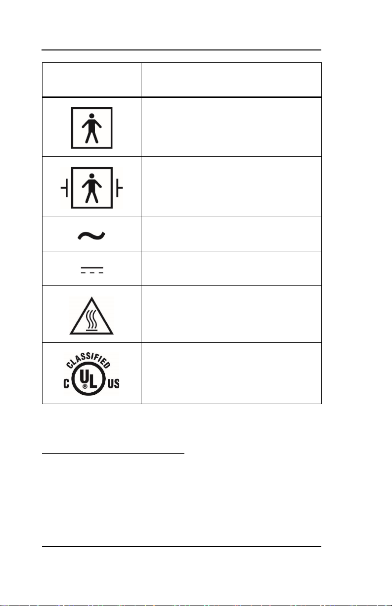
Table 1. Safety Symbol Definitions
Symbol Definition
WARNING
Warnings alert users to potential serious outcomes
(death, injury, or adverse events) to the patient, user, or
environment.
Caution
Cautions alert users to exercise appropriate care for safe
and effective use of the product.
Note
Notes provide additional guidelines or information.
Page 16

Warnings
16
BIS™ Complete Monitor
2.3. Warnings
WARNING:
Explosion hazard: do not use the BIS™ complete system in a
flammable atmosphere or where concentrations of flammable
anesthetics may occur.
WARNING:
Monitor is not designed for use in MRI environment.
WARNING:
Use only the power cord supplied by the manufacturer. Never
adapt the plug from the monitor to fit a non-standard outlet.
WARNING:
U.S.A. requirement: for proper grounding, the power
receptacle must be a three-wire grounded outlet. A hospital
grade outlet is required. Never adapt the three-prong plug
from the monitor to fit a two-slot outlet. If the outlet has only
two slots, make sure that it is replaced with a three-slot
grounded outlet before attempting to operate the monitor.
WARNING:
If the integrity of the external protective earth ground is in
doubt, the BIS™ complete system shall be operated from its
internal battery power source only.
WARNING:
Be sure the monitor is mounted securely in place to avoid
personal or patient injury.
WARNING:
The BIS™ complete monitor should not be used adjacent to or
Page 17

Warnings
BIS™ Complete Monitor
17
stacked with other equipment. If adjacent or stacked use is
necessary, the BIS™ complete monitor should be observed to
verify normal operation in the configuration in which it will be
used.
WARNING:
When connecting external equipment (e.g., data capture
computer), the system leakage current must be checked and
must be less than the IEC 60601-1-1 limit.
WARNING
Using accessories other than those specified may result in
increased electromagnetic emissions or decreased
electromagnetic immunity of the BIS™ complete monitoring
System.
WARNING:
The use of accessory equipment not complying with the
equivalent safety requirements of this equipment may lead to a
reduced level of safety of the resulting system. Consideration
relating to the choice shall include:
o Use of the accessory in the patient vicinity.
Evidence that the safety certification of the accessory
has been performed in accordance to the appropriate
IEC 60601-1 and/or IEC 60601-1-1 harmonized
national standard.
Due to elevated surface temperature, do not place the BISX™
unit in prolonged direct contact with patient’s skin, as it may
cause discomfort.
The conductive parts of electrodes or sensor and connectors
should not contact other conductive parts, including earth.
WARNING:
WARNING:
Page 18

Warnings
18
BIS™ Complete Monitor
WARNING:
To reduce the hazard of burns during use of high-frequency
surgical equipment, the sensor or electrodes should not be
located between the surgical site and the electro-surgical unit
return electrode.
WARNING:
To reduce the hazard of burns during use of brain-stimulating
devices (e.g., transcranial electrical motor evoked potential),
place stimulating electrodes as far as possible from the BIS™
sensor and make certain that sensor is placed according to
package instructions. The sensor must not be located between
defibrillator pads when a defibrillator is used on a patient
connected to the BIS™ complete system.
WARNING:
To minimize the risk of patient strangulation, the patient
interface cable (PIC) must be carefully placed and secured.
WARNING:
Shock Hazard: Do not attempt to disconnect the power cord
with wet hands. Make certain that your hands are clean and dry
before touching the power cord.
WARNING:
Universal precautions shall be observed to prevent contact
with blood or other potentially infectious materials. Place
contaminated materials in regulated waste container.
WARNING:
Do not mix disinfecting solutions (e.g., bleach and ammonia),
as hazardous gases may result.
Page 19

Warnings
BIS™ Complete Monitor
19
WARNING:
Electrical Shock Hazard: Do not remove monitor covers during
operation or while power is connected to monitor.
WARNING:
Electrical Shock Hazard: The manufacturer's inspection of this
apparatus verified that the ground leakage current and the
patient safety current were less than the specified limits
established by the applicable safety standards. As a matter of
safe practice, the institution should conduct periodic tests to
verify these currents.
WARNING:
Whenever an event such as spillage of blood or solutions
occurs, re-test ground leakage current before further use.
WARNING:
Leakage current must be checked by a qualified biomedical
engineering technician whenever instrument case is opened.
WARNING:
Power supply is internally fused. Replace power supply only
with Covidien BIS Complete power supply.
Portable RF communications equipment (including peripherals
such as antenna cables and external antennas) should be used
no closer than 30 cm (12 inches) to any part of the BIS™
complete monitoring system, including cables specified by the
manufacturer. Otherwise, degradation of the performance of
this equipment could result.
Check Target Range alarm limits to ensure they are appropriate
WARNING:
WARNING:
Page 20

Cautions
20
BIS™ Complete Monitor
for the patient being monitored with each use. Ensure Target
Range alarm limits do not exceed the standard thresholds set
by the institution.
WARNING:
Do not decrease the adjustable alarm volume below ambient
sound levels. Decreasing the alarm volume below ambient
levels may compromise patient safety.
2.4. Cautions
Caution:
Read this entire manual carefully before using the monitor in a
clinical setting. Do not autoclave the BISX™ unit or monitor.
Autoclaving will seriously damage both components.
Caution:
Do not set the Target Range alarm limits to extreme values that
render the monitoring system useless. Ensure Target Range alarm
limits are appropriate for each patient.
Caution:
Do not block ventilation inlet holes on the underside of monitor.
Caution:
Do not open BISX™ unit for any reason. The seal to prevent liquids
from entering the BISX™ unit may be damaged if opened.
Caution:
Service or repairs must be performed only by qualified biomedical
technicians.
Page 21

Cautions
BIS™ Complete Monitor
21
Caution:
The BIS™ complete system has been designed to operate with a
BIS sensor. The sensor is a silver/silver chloride electrode array
that utilizes Covidien's patented Zipprep™ technology and uses a
proprietary connector. Use of other electrodes is not
recommended.
Caution:
To completely remove power from the unit: put the monitor in
Standby mode, disconnect power cord from the power receptacle
of the monitor, then remove the battery from the monitor.
Caution:
Continuous impedance checking may need to be disabled if the 1
nanoampere 128 Hz impedance check signal interferes with other
equipment (e.g., evoked potential monitors).
Caution:
Considerations when using Electro-Convulsive Therapy (ECT)
equipment during BIS™ monitoring: Place ECT electrodes as far as
possible from the BIS sensor to minimize the effect of
interference. Certain ECT equipment may interfere with the
proper function of the BIS™ monitoring system. Check for
compatibility of equipment during patient setup.
Caution:
Check the battery annually by operating a BIS™ complete monitor
that has been disconnected from the wall socket and that has
been charged to full capacity (at least 6 hours of charge time).
After long periods of storage, charge the battery for 6 hours to
assure full capacity. If the BIS™ complete monitor fails to operate
reliably from the battery for approximately 3 hours (or 2 hours
with BISX™ or BISX4™ unit attached), battery replacement is
required.
Page 22

Cautions
22
BIS™ Complete Monitor
Caution:
Check the battery pack annually to ensure that the expiration date
listed on the battery pack is not exceeded. If the expiration date is
exceeded, then dispose of the battery.
Reference 6.3.5 Checking Battery Expiry Date on page 149, for
instructions on how to access battery and expiration date.
Caution:
The BIS™ complete monitor contains an internal Lithium ion
battery. The battery must be removed by a qualified service
technician and disposed of or recycled in accordance with the
national laws of the country. Contact Covidien or the local
distributor for a replacement battery: Covidien part number 186-
0208.
Caution:
Avoid liquid ingress to the Patient Interface Cable. Contact of
fluids with the PIC sensor connector can interfere with PIC
performance. Service or repairs must be performed only by
qualified biomedical technicians.
Caution:
The BIS™ complete system complies with the electromagnetic
compatibility requirements of IEC 60601-1-2. Operation of this
device may affect or be affected by other equipment in the
vicinity due to electromagnetic interference (EMI). If this occurs:
o Increase separation between devices.
Re-orient device cabling.
Plug devices into separate outlet circuit branches.
Reference 9.2 Electromagnetic Compatibility Specifications
on page 195.
Caution:
Do not disconnect the BISX™ unit during the software update.
Page 23
Key to Symbols
BIS™ Complete Monitor
23
Caution:
When connecting or disconnecting BISX™ unit, take care not to
touch the exposed contacts of either connector. Damage due to
electrostatic discharge may result.
Important: The BIS™ complete system complies with the European
Medical Device Directive (MDD) and applicable regulatory requirements
of the country distributed to and carry the CEXXXX Marking.
Declarations of Conformity provided upon request where appropriate.
2.5. Key to Symbols
A key to the symbols that may appear on the BIS™ Complete system
appears below.
Table 2. Symbol Key
Symbol
Description
Latex Free product
Do Not Reuse
Page 24
Key to Symbols
24
BIS™ Complete Monitor
Symbol
Description
Caution: Consult Accompanying
Documents
Follow Instructions for Use
Consult Instructions for Use
Storage Temperature Limits
Packaging Labeling: Fragile
Packaging Labeling: Do Not Get Wet
Page 25
Key to Symbols
BIS™ Complete Monitor
25
Symbol
Description
Packaging Labeling: This Side Up
Recyclable
Product marked with the “e” does not
contain any toxic or hazardous substances
or elements, and is green and
environmental. The product can be
recycled.
Product marked with a number contains
certain toxic or hazardous substances or
elements, and can be used safely during its
Environment-Friendly Use Period (EFUP).
The product should be recycled. The
Environment-Friendly Use Period is valid
only when the product is operated under
the conditions defined in the product
manual.
1
In regards to European Union Directive 2006/66/EC on batteries and accumulators and waste
batteries and accumulators: The Batteries Directive, 2006/66/EC, introduced new
Crossed out wheelie bin indicates separate
treatment from general waste at end of life
1
Page 26
Key to Symbols
26
BIS™ Complete Monitor
Symbol
Description
Type BF Equipment
Type BF Equipment Defibrillator-proof
Alternating Current
Direct Current (D/C)
Caution: Hot Surface
Classified by Underwriters Laboratories
Inc.® with respect to electric shock, fire and
mechanical hazards only, in accordance
with UL 60601-1 and IEC60601-2-26
requirements, effective September 26, 2008, regarding removability of batteries from
waste equipment in EU Member States. To comply with this Directive, this device has
been designed for safe removal of the batteries at end-of-life by a qualified service
technician. Infected units should be de-contaminated before they are sent for recycling,
in accordance with Ca
Directive 2002/96/EC on waste electrical and electronic equipment (WEEE). All waste
electrical and electronic equipment (WEEE) should be disposed of and collected
separately. This product is Electrical and Electronic Equipment and should be disposed of
in accordance with national and local legislation and requirements.
re and Clea ning (6.2) o
f this manual. In regards to European Union
Page 27
Key to Symbols
BIS™ Complete Monitor
27
Symbol
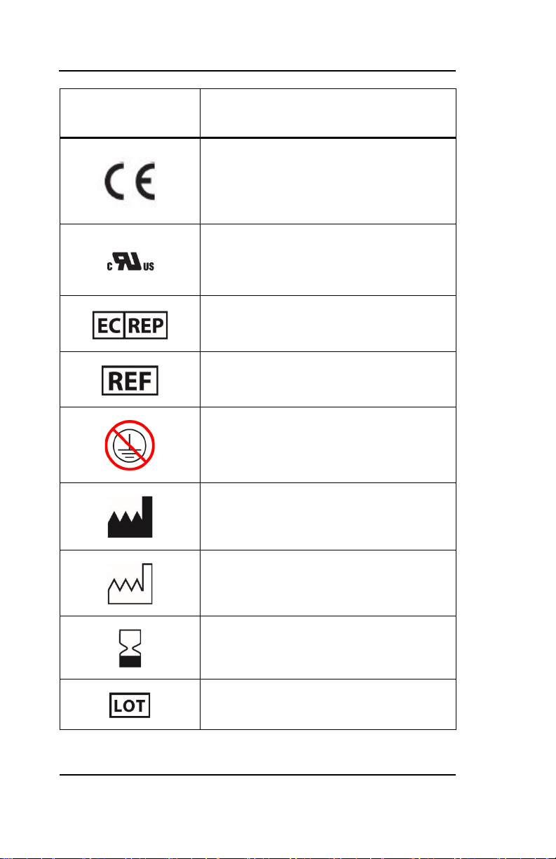
Description
Conformité Européenne (CE) Marking of
Conformity to European Medical Device
Directive. CEXXXX represents the Notified
Body number
Recognized under the Component
Recognition Program of Underwriters
Laboratories Inc.
Authorized Representative in the European
Community
Catalog Number
Not connected to protective earth
Manufacturer
Manufacturer Date
Use by YYYY-MM-DD or YYYY-MM
Batch Code
Page 28
Key to Symbols
28
BIS™ Complete Monitor
Symbol
USB-A
USB-B
Description
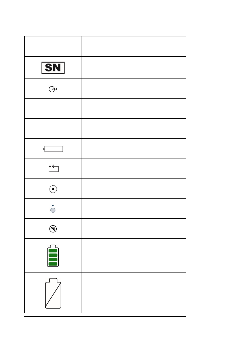
Serial Number
Data I/O, RS-232 Serial Port
Universal Serial Bus: Type A
Universal Serial Bus: Type B
Battery Location
Reset Button
Monitor Power ON
Monitor Power OFF or Standby Mode
PVC-free product
Operating on Battery
No Battery is Installed in Monitor
Page 29
Key to Symbols
BIS™ Complete Monitor
29
Symbol
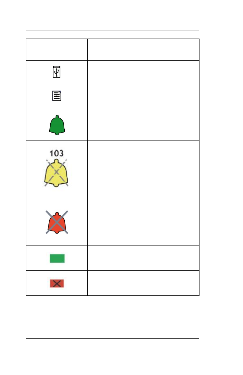
Description
USB Drive: Data Export is in Progress
A Printable File Is Being Transferred to the
USB Drive
Green Bell Icon – Alarms Active
Yellow Bell with Countdown Timer – Alarms
Paused
Red Bell with ‘X’ – Alarms Silenced
NOTE: When alarms are silenced, an audible
reminder sounds at 3-minute intervals. This
reminder can be disabled via the
Maintenance Menu (passkey protected).
A green box denotes ON or active
condition.
A red box with an ‘X’ denotes OFF or cancel.
Page 30

Page 31

3. Installation and
Preparation for Use
3.1. Introduction
This chapter provides installation instructions for the BIS™ complete
monitor, BISX™ unit, and accessories. It includes:
• Installation checklist
• Proper environment
• Required equipment and supplies
• Cable connections
• Start and shutdown procedures
• Initial menu settings
The system is seen in Figure 2. The BIS™ Complete Monitoring System on
page 43.
3.2. BIS™ Complete Monitor
Installation and Checkout
1. Open packages and inspect for all components:
• Monitor
• Power cord
Page 32

BIS™ Complete Monitor Installation and Checkout
32
BIS™ Complete Monitor
• Pole clamp
• BISX™ unit
• PIC (Patient interface cable, connects BISX™ unit to patient)
Sensors are sold separately. For a list of available sensors please contact
Covidien or your local distributor.
2. Connect power cable to monitor, plug power plug into
appropriate wall outlet. Ensure that the outlet used for the
monitor is easily accessible; disconnection from the outlet is
the only way to completely remove AC power to the monitor.
• Verify that light to right of ON/Standby button is yellow.
3. Start up monitor by pressing the ON/Standby button (lower
right corner).
• Verify that light to right of ON/Standby button is green.
• Verify all self-tests complete successfully.
• Verify next screen says “Connect BISX.”
4. Connect BISX™ with PIC to monitor.
• Verify screen says “BISX Initialization Complete.”
• Verify screen says “Connect sensor or cable.”
5. Connect PIC and sensor.
• Verify SENSOR CHECK begins.
6. Disconnect power cord from monitor.
• Verify ‘OPERATING ON BATTERY BACKUP’ is displayed.
• Verify battery icon displays below BIS™ number.
Page 33

Environment
BIS™ Complete Monitor
33
7. Reconnect power cord.
Item
Value
Temperature
-20°C to +60°C (-4°F to 140°F)
Humidity
15% to 95% (non-condensing)
Pressure
800 mm Hg (1500 feet below sea level) to
• Verify battery icon is not displayed below BIS™ banner.
• Verify “OPERATING ON BATTERY BACKUP” is not displayed.
8. End of install.
3.3. Environment
3.3.1. Shipping and Storage
Environment
The monitor and its accessories can be stored or shipped within the
following environmental limits. Note that these limits apply to nonoperational storage and shipping situations.
Table 3. Shipping and Storage Environment
360mm Hg (20,000 feet above sea level)
Protect the monitor from sudden temperature changes that can lead to
condensation within the instrument. To minimize condensation, avoid
moving the system between heated buildings and outside storage. Once
moved inside, allow the monitor to stabilize in the unopened shipping
container at the inside ambient temperature before unpacking and
Page 34

Environment
34
BIS™ Complete Monitor
Item
Value
Temperature
0°C to +40°C (32°F to 104°F)
Humidity
15% to 95% (non-condensing)
Pressure
800 mm Hg (1500 feet below sea level) to
placing into service. Before operation, wipe down all visible
condensation and allow the system to reach equilibrium at room
temperature.
3.3.2. Operating Environment
The BIS™ complete monitoring system is not designed for use in areas
containing flammable gases or vapors.
WARNING:
Explosion hazard: do not use the BIS™ complete system in a
flammable atmosphere or where concentrations of flammable
anesthetics may occur.
WARNING:
Monitor is not designed for use in MRI environment.
The BIS™ complete monitor is designed to operate safely under the
following conditions. Conditions outside these ranges could affect
reliability.
Table 4. Operating Environment
360mm Hg (20,000 feet above sea level)
Page 35

Environment
BIS™ Complete Monitor
35
3.3.3. Power Requirements and System
Grounding
The BIS™ complete monitoring system requires a power source of 100–
240 VAC, 50–60Hz. Current consumption is 0.7 ampere maximum.
To protect operating personnel and patients, the monitor must be
properly grounded. Accordingly, the monitor is equipped with a hospital
grade line cord. The power cord grounds the system to the power line
ground when plugged into an appropriate three-wire receptacle.
WARNING:
Use only the power cord supplied by the manufacturer. Never
adapt the plug from the monitor to fit a non-standard outlet.
WARNING:
U.S.A. requirement: For proper grounding, the power
receptacle must be a three-wire grounded outlet. A hospital
grade outlet is required. Never adapt the three-prong plug
from the monitor to fit a two-slot outlet. If the outlet has only
two slots, make sure that it is replaced with a three-slot
grounded outlet before attempting to operate the monitor.
If the integrity of the external protective earth ground is in
doubt, the BIS™ complete monitor shall be operated from its
internal battery power source only.
3.3.4. Electromagnetic Compatibility
The BIS™ complete monitoring system should be used only with the
power cord and accessories recommended and supplied by Covidien.
The system must be installed and put into use according to the
WARNING:
Requirements
Page 36

Environment
36
BIS™ Complete Monitor
specifications described in
.
(B.2)
Electromagnetic Compatibility Specifications
Caution:
The BIS™ complete system complies with the electromagnetic
compatibility requirements of IEC 60601-1-2. Operation of this
device may affect or be affected by other equipment in the
vicinity due to electromagnetic interference (EMI). If this occurs:
o Increase separation between devices.
Re-orient device cabling.
Plug devices into separate outlet circuit branches.
Refer to 9.2 Electromagnetic Compatibility Specifications on
page 195.
3.3.5. Site Preparation: Mounting the
Monitor
Covidien strongly recommends permanent mounting of the BIS™
complete monitor to the anesthesia machine to enhance safety and
facilitate ease-of-use. Please contact your local representative or
Covidien to discuss mounting options.
Mounting the Monitor using the Pole Clamp
To mount the monitor to a secure vertical pole (1/2" – 1½" in diameter):
1. Place pole within clamp bracket and tighten screw using the
WARNING:
Be sure the monitor is mounted securely in place to avoid
personal or patient injury.
black finger knob. Make sure that there is enough space above
the clamp so that you have a few inches to slide the monitor in
from above.
Page 37

Environment
BIS™ Complete Monitor
37
2. Line up the clamp shoe (on back of monitor) with the slot on
pole clamp and slide monitor down to fit. The bottom of the
clamp shoe should be seen well below the bottom of the pole
clamp, and the monitor should snap securely into place.
Figure 1. Pole Clamp
To remove the monitor, press tab on top of clamp shoe before sliding
monitor up.
The pole clamp may be locked onto the monitor so that the two do not
get separated. To do this:
Page 38

The BIS™ Complete Monitoring System—Equipment and Supplies
38
BIS™ Complete Monitor
1. Line up the clamp shoe (on back of monitor) with the slot on
pole clamp and slide monitor down to fit. The bottom of the
clamp shoe should be seen well below the bottom of the pole
clamp and the monitor should snap securely into place.
2. Make sure that set screw hole on pole clamp aligns with
corresponding hole on clamp shoe.
3. Remove black knob screw from pole clamp.
4. Using the Allen wrench supplied, secure pole clamp to monitor
with the set screw provided.
5. Replace black knob screw.
6. To attach to pole, place pole within clamp bracket and tighten
screw using the black finger knob.
3.4. The BIS™ Complete
Monitoring System—
Equipment and Supplies
The BIS™ complete monitoring system consists of the following basic
components:
• BIS™ complete monitor
• BISX™ unit
• Patient Interface Cable (PIC)
• BIS™ sensor
• Detachable Power Cord
Sensors are sold separately. For a list of available sensors please contact
Covidien or your local distributor.
Page 39

The BIS™ Complete Monitoring System—Equipment and Supplies
BIS™ Complete Monitor
39
A pole clamp is also included; however, its use is optional. Contact
Covidien or your local representative for information on additional
equipment and accessories.
Product names for some components of the BIS™ complete monitoring
system have changed. For current vs. legacy product names, refer to
Table 5. Current vs. Legacy BIS Complete Monitoring System Product
Names, below.
Table 5. Current vs. Legacy BIS Complete Monitoring System
Product Names
Current
Product Name
BIS™ complete
monitor
Legacy
Product Name
BIS™ Vista
monitor
LoC 2 Channel BISX™
Description or
Application
BIS™ monitor
that can be
used with
either a 2 or 4
Channel LoC
device.
Monitor is
connected to
the LoC device
by a BIS Host
Cable which is
packaged with
the LoC
device.
Processes 2
channels of
EEG
information
(one side of
the brain) and
calculates an
index (0-100)
that provides a
direct measure
Part Number
185-0151
186-1100
185-1014-
xxx
Page 40

The BIS™ Complete Monitoring System—Equipment and Supplies
40
BIS™ Complete Monitor
of the patient's
Current
Product Name
Legacy
Product Name
LoC 4 Channel BISX4™
Description or
Application
level of
consciousness.
Connects to a
BIS sensor by
the 10-pin
Patient
Interface Cable
(PIC) which is
packaged with
the LoC
device.
Processes 4
channels of
EEG
information
(both sides of
the brain) and
calculates an
index (0-100)
that provides a
direct measure
of the patient's
level of
consciousness.
Part Number
185-1016-
xxx
Connects to a
BIS sensor by
the 12-pin
Patient
Interface Cable
(PIC) which is
packaged with
the LoC
device.
Page 41

The BIS™ Complete Monitoring System—Equipment and Supplies
BIS™ Complete Monitor
41
Current
of the LoC 4
Product Name
BIS™ Sensors
Legacy
Product Name
Description or
Application
Part Number
Quatro Quatro
Extend Extend
Pediatric Pediatric
Bilateral Bilateral
Sensor for
adult patients
undergoing
general
anesthesia or
sedation.
Sensor for
adult patients
undergoing
general
anesthesia or
sedation in
environments
such as the
ICU.
Sensor for
pediatric
patients ages
four and up.
Sensor that
detects
hemispheric
differences in
the brain (for
advanced
monitoring
applications).
Requires use
186-0106
186-0160
186-0200
186-0212
Page 42

The BIS™ Complete Monitoring System—Equipment and Supplies
42
BIS™ Complete Monitor
Channel
Current
Product Name
Legacy
Product Name
Description or
Application
Part Number
device.
Table 6. Summary of Cables used with the BIS Complete
Monitoring System
Cable Location Comment
AC Power Back of Monitor
Provided by
Manufacturer
USB (Type A)2 Back of Monitor Provided by Customer
USB (Type A) Port is
used with removable
drive only
RS-232 Back of Monitor Provided by Customer
(1m < Length < 3m)
Monitor Interface
Cable
Front of Monitor Side of LoC
Provided by
Manufacturer
(see
Specifications
192)
2
USB (Type B) Port is for manufacturing use only. See 4.11 Data Transfer 106
9.1.3 BISX™ Unit
on page
Page 43

The BIS™ Complete Monitoring System—Equipment and Supplies
BIS™ Complete Monitor
43
Cable Location Comment
1
Monitor Interface Cable
4
Patient Interface Cable
2
BIS™ complete monitor
5
BISX™
3
BIS™ sensor
Patient Interface
Cable
Figure 2. The BIS™ Complete Monitoring System
Side of LoC – BIS™
Sensor
Provided by
Manufacturer
(see
9.1.3 BISX™ Unit
Specifications
192)
on page
(PIC)
Page 44

The BIS™ Complete Monitoring System—Equipment and Supplies
44
BIS™ Complete Monitor
3.4.1. BIS™ Complete Monitor
Front Panel
The front panel of the BIS™ complete monitor contains the Touch Screen,
BISX™ port and the ON/Standby button. See Figure 2. The BIS™ Complete
Monitoring System on page 43.
Touch Screen
The BIS™ complete monitor is designed so that all controls (with the
exception of the ON/Standby button) are accessible by touching a
designated area on the monitor screen. This area is called a touch key.
The touch keys are designed to function even when the user is wearing
examination gloves.
ON/Standby Button
The ON/Standby button is located in the lower right corner of the
monitor and indicates whether the monitor is ON or in Standby mode.
When the small LED light to the right of the ON/Standby button is green,
the unit is running and providing power to the BISX™ unit. When it is
yellow, the battery is charging, and the system is in Standby mode.
When it is not lit, no A/C power is available to the unit; pressing the
ON/Standby button will start up the monitor using the battery.
Rear Panel
The rear panel components are pictured in Figure 3. Rear Panel on page
45. They include: two USB ports (Type A and B), the clamp shoe, an RS-
Page 45

The BIS™ Complete Monitoring System—Equipment and Supplies
BIS™ Complete Monitor
45
232 port, the Reset button, the Battery/Power Supply cover, and the
1
Battery/Power Supply Cover
5
Serial Port
power cord receptacle.
Note:
Do not touch the patient and the RS-232 or USB ports at the
same time.
Figure 3. Rear Panel
Page 46

The BIS™ Complete Monitoring System—Equipment and Supplies
46
BIS™ Complete Monitor
2
USB Port (Type B)
6
Power Cord Receptacle
3
USB Port (Type A)
7
Clamp Shoe
4
Reset Button
There are two USB ports on the rear of the monitor. The Type A port is
used to export data to a removable drive. It is also used to update
monitor and BISX™ software.
The clamp shoe allows the monitor to slide into the pole clamp so that it
can be attached to a ½" – 1 ½" diameter vertical pole.
The RS-232 serial port can be used to transfer data from the monitor.
WARNING:
When connecting external equipment (e.g., data capture
computer), the system leakage current must be checked and
must be less than the IEC 60601-1-1 limit.
WARNING:
The use of accessory equipment not complying with the
equivalent safety requirements of this equipment may lead to a
reduced level of safety of the resulting system. Consideration
relating to the choice shall include:
o Use of the accessory in the patient vicinity
Evidence that the safety certification of the accessory
has been performed in accordance to the appropriate
IEC 60601-1 and/or IEC 60601-1-1 harmonized
national standard.
Under normal operation, power is cycled through the ON/Standby
button. The Reset button can be used to reset the software functions of
Page 47

The BIS™ Complete Monitoring System—Equipment and Supplies
BIS™ Complete Monitor
47
the BIS™ monitor (and the BISX™ unit if it is attached) in the unlikely case
that it is required. See 2.5 Key to Symbols on page 23.
The Battery/Power Supply cover contains the BIS™ complete monitor’s
power supply and allows access to its battery.
The power cord receptacle, located on the side of the Battery/Power
Supply cover, is used to plug in the power cord provided by the
manufacturer. It provides power to the monitor and to the BISX™ unit
when it is attached.
Caution:
The BIS™ complete monitoring system complies with the
electromagnetic compatibility requirements of IEC 60601-1-2.
Operation of this device may affect or be affected by other
equipment in the vicinity due to electromagnetic interference
(EMI). If this occurs:
o Increase separation between devices.
Re-orient device cabling.
Plug devices into separate outlet circuit branches.
Refer to 9.2 Electromagnetic Compatibility Specifications on
page 195.
Integral Battery
A rechargeable lithium ion battery inside the monitor provides
approximately 45 minutes of back-up power when power cannot be
supplied via the power cord. Recharge time is approximately 6 hours.
The battery charges continually as long as the unit is plugged into A/C
power.
When the system is running on battery, a battery icon displays indicating
the battery status. A battery icon with four green bars indicates that the
battery is fully charged. When the battery reaches a low power
condition, the monitor beeps and the battery symbol displayed on the
screen changes color. In addition, a “Battery Voltage Low” message
blinks in the Message area of the screen.
Page 48

The BIS™ Complete Monitoring System—Equipment and Supplies
48
BIS™ Complete Monitor
1
Monitor Interface Cable
2
Patient Interface Cable
Caution:
Check the battery annually by operating a BIS™ complete monitor
that has been disconnected from the wall socket and that has
been charged to full capacity (at least 6 hours of charge time).
After long periods of storage, charge the battery for 6 hours to
assure full capacity. If the BIS™ complete monitor fails to operate
reliably from the battery for approximately 45 minutes, battery
replacement is required.
Caution:
The BIS™ complete monitor contains an internal lithium ion
battery. The battery must be removed by a qualified service
technician and disposed of or recycled in accordance with the
national laws of the country. Contact Covidien or the local
distributor for a replacement battery.
3.4.2. BISX™ Unit
Figure 4. BISX™ Unit and PIC
(PIC)
Page 49

The BIS™ Complete Monitoring System—Equipment and Supplies
BIS™ Complete Monitor
49
The BISX™ unit receives, filters, and processes patient EEG signals. It is
located close to the patient's head where the EEG signal is less subject to
interference from other medical equipment.
The BISX™ unit is shown in Figure 4. BISX™ Unit and PIC on page 48. Its
long flexible Monitor Interface Cable connects to the front of the
monitor. The Patient Interface Cable (PIC) connects the BIS™ sensor to
the BISX™ unit.
The attachment clip on the BISX™ unit is used to secure it in a convenient
location near the patient's head.
WARNING:
Due to elevated surface temperature, do not place BISX™ unit
in prolonged direct contact with patient’s skin, as it may cause
discomfort.
Caution:
Do not open BISX™ unit for any reason. The seal to prevent liquids
from entering the BISX™ unit may be damaged if opened. Service
or repairs must be performed only by qualified biomedical
technicians.
3.4.3. Patient Interface Cable (PIC)
Covidien BIS™ sensor patient interface cable (PIC) (see Figure 2. The BIS™
Complete Monitoring System on page 43) connects the BISX™ unit to the
BIS™ sensor.
3.4.4. BIS Sensors
The sensor is the single use component of the BIS™ monitoring system
and should be replaced after each use. For details on how to apply the
sensor to the patient and how to connect to the BIS™ monitoring system,
Page 50

Cable Connections
50
BIS™ Complete Monitor
refer to the BIS™ sensor instructions for use. All sensors, including the
BIS™ extended use sensor, utilize the monitor’s saved settings (such as
smoothing rate).
3.5. Cable Connections
After you have familiarized yourself with the safety information in the
introductory section of this manual and have prepared a suitable
environment, follow these steps to prepare the BIS™ complete system
for operation.
1. Connect the BISX™ unit to the monitor
Holding the cylindrical connector with the flat side up, plug the BISX™
monitor interface cable into the BISX™ port on the front of the monitor.
Once connected, the BISX™ unit need not be disconnected again.
However, if you wish to disconnect the BISX™ cable from the monitor,
carefully grasp the connector and pull. DO NOT pull on the cable.
2. Connect the PIC to the BISX™ unit.
Attach the gray connector of the Patient Interface Cable to the BISX™
unit.
Note:
Connect with the BIS™ logo facing up for proper pin alignment.
To disconnect the PIC, grasp the connector housing and pull
firmly. DO NOT pull apart by the cable wire.
Page 51

Start Procedure / Standby Mode
BIS™ Complete Monitor
51
3.6. Start Procedure / Standby
Mode
3.6.1. Starting the Monitor for the First
Time
To start the instrument for the first time, after it has been reset with the
RESET button, or after battery replacement:
1. Attach one end of the power cord to the receptacle on the left
side of the monitor.
2. Plug the other end of the power cord into a properly grounded
hospital-grade AC power outlet. A yellow light illuminates to
the right of the ON/Standby button.
3. Press the ON/Standby button. The light changes to green and
diagnostics tests run to verify that the system is operating
properly. A beep indicates that the tests are complete. If there
is a problem, the system halts and an error message appears.
Error messages are explained in the Troubleshooting section of
this manual.
When not in use, the monitor should be placed in Standby mode. To put
the system in Standby mode, press and hold the ON/Standby button for
two seconds before releasing. The light will change from green to
yellow. If the monitor is running on battery, the light will go off
completely.
3.6.2. Starting the Monitor from Standby
When the monitor is in Standby mode (yellow light), you may start it by
pressing the ON/Standby button. The light will change to green.
Mode
Page 52

Start Procedure / Standby Mode
52
BIS™ Complete Monitor
Setting
Description
Alarm volume
Saved alarm volume setting will be restored
Charting
Saved charting interval setting will be restored
Device will restore date and time based on the last
Diagnostic
Saved diagnostic codes setting will be restored
When not in use, the monitor should be placed in Standby mode. To put
the system in Standby mode, press and hold the ON/Standby button for
two seconds before releasing. The light will change from green to
yellow. If the monitor is not connected to A/C power, the light will go off
completely.
3.6.3. Power-Up Messages
At power-up, the following message will appear in the Message Region
of the screen:
• “Saved settings restored”
This message appears at each power-up, both after normal shutdown
and after an unexpected shutdown. See Table 7. Summary of Settings
Restored after System Start, below for the list of settings restored.
After an unexpected shutdown, such as a power failure, a black screen
with a Hardware Timer error message will be shown, with a [Continue]
button.
Table 7. Summary of Settings Restored after System Start
interval
Date and time
time saved on the monitor and elapsed time since
that time
codes
Page 53

Start Procedure / Standby Mode
BIS™ Complete Monitor
53
Display SR
Saved SR setting will be restored
Filters
Saved EEG Filters setting will be restored
Impedance
Checking
Saved Impedance Checking setting will be
Language
User selected language will be restored
Monitor Mode
User Selected Mode will be restored
DSA graph
Saved DSA graph direction (vertical or horizontal)
Secondary
Saved secondary variable displayed in the BIS
Sensor Check
Saved Sensor Check Values setting will be
Serial Protocol
Saved Serial Protocol setting will be restored
Target High
Target Low
restored
Orientation
Variable
Values
will be restored
trend display will be restored
restored
Limit Saved target high alarm limit will be restored
Limit Saved target low alarm limit will be restored
Page 54

Initial Menu Settings
54
BIS™ Complete Monitor
For all other user-adjustable settings, the manufacturer recommends
that the user re-check these settings after a system restart, to ensure
that the settings meet user requirements.
3.7. Initial Menu Settings
Before using the BIS™ complete monitor for the first time, you may need
to select the proper language and set the current date and time. Other
setting options are discussed in detail in
Monitoring System (4)
The BIS™ complete monitor utilizes a touch screen. To access the Menus,
press the [MENU] icon on the left side of the screen. Press the [Next] or
[Previous] touch keys to scroll through the menu options. At any time,
you may press the [HOME] touch key to return to the main display
screen.
.
3.7.1. Language Selection
The BIS™ complete monitor is designed to support multiple languages. If
the screen does not display the desired language, follow these steps:
Opera ting the BIS™ Complete
To change the language:
1. Press [MENU].
2. Press [Next] to go to the second menu, then [Next] again to go
3. Press [Language]. The current language is displayed.
4. Use the [+] or [-] keys to scroll through the list of languages
5. Press [HOME] to return to the main screen.
to the third menu.
until the desired language appears. All screens will now display
in the selected language.
Page 55

Initial Menu Settings
BIS™ Complete Monitor
55
3.7.2. Date and Time
To set the current date and time:
1. Press [MENU].
2. Press [Next] to go to the second menu, then [Next] again to go
to the third menu.
3. Press [Date and Time]. A new screen displays the current date
and time. “Day” is displayed in blue letters.
4. Use the up and down arrows to set the day of the month.
5. Press [Month]. “Month” is displayed in blue letters.
6. Use the up and down arrows to set the month.
7. Repeat this process for the “Year,” “Hour,” “Minute” and
“Second” displays.
8. Press [Apply Changes] to apply the changes that you have just
made.
9. When you have finished, you may press [Return to Previous
Menu] or press [HOME] to return to the main screen.
The time/date is initially set for the Eastern Standard or Eastern
Daylight Time zone (USA). It will be necessary for you to change
the time twice per year using the Time/Date feature if you are
located in a time zone that alters its clocks at the beginning or
end of Daylight Savings Time.
3.7.3. View/Save Settings
The BIS™ complete monitor will always start up configured to settings
that have been saved in memory.
Note:
Page 56

Initial Menu Settings
56
BIS™ Complete Monitor
To save the current configuration settings,
1. Press [MENU].
2. Press [View/Save Settings]. The current settings display.
3. Press [Save Active]. A passkey is required to save the settings
3.7.3 View/Save Settings
(see
entering the passkey). The message, “Settings Saved” appears.
The settings displayed will be saved except as noted below.
4. Press [Previous] or [HOME] to exit.
on page 55 for information about
Note:
The “Save Active” option is disabled when in Battery BackupLow Power condition.
Monitor Mode in current use is also saved when the “Save
Active” button is pressed. The following settings are not saved
by the “Save Active” option: Impedance Checking (always
returns to ON), Filters (returns to ON), and Display Type
(returns to BIS™).
Settings are set and saved for the current Monitor Mode only. See 4.6.10
Monitor Mode on page 92.
See 3.7.3 View/Save Settings on page 55 for instructions on restoring
factory default values.
Page 57

BIS™ Complete Monitor
57
4. Operating the BIS™
Complete Monitoring
System
4.1. Introduction
This chapter covers:
• Preparing for operation
• The sensor check
• The monitor screen display
• Software menus and menu selections
• Reviewing stored data
• The EEG display
• Ending a case
Read this chapter before operating the monitor in a clinical setting.
4.2. Preparing for Operation
After you have familiarized yourself with the safety information in the
introductory section of this manual, prepared a suitable environment,
properly connected the BISX™ unit and PIC cables, and completed the
initial settings described in 3.7 Initial Menu Settings on page 54, follow
Page 58

Preparing for Operation
58
BIS™ Complete Monitor
these steps to prepare the BIS™ complete monitoring system for
operation.
1. Startup and System Check
Press the ON/Standby button on the lower right corner of the monitor to
start the monitor. The light changes from yellow to green, and the
system initiates a self-test to make sure that all equipment is operating
properly.
2. Attach BIS™ Sensor to Patient
Prepare sensor site and place the BIS™ sensor on the patient in
accordance with the instructions included on the sensor packaging.
Caution:
The BIS™ complete monitoring system has been designed to
operate with a BIS™ sensor. The sensor is a silver/silver chloride
electrode array that utilizes Covidien’s patented Zipprep™
technology and uses a proprietary connector. Use of other
electrodes is not recommended.
The conductive parts of electrodes or sensor and connectors
should not contact other conductive parts, including earth.
To reduce the hazard of burns during use of high-frequency
surgical equipment, the sensor or electrodes should not be
located between the surgical site and the electro-surgical unit
return electrode.
The sensor must not be located between defibrillator pads
WARNING:
WARNING:
WARNING:
Page 59

Preparing for Operation
BIS™ Complete Monitor
59
when a defibrillator is used on a patient connected to the BIS™
complete system.
WARNING:
To minimize the risk of patient strangulation, the patient
interface cable (PIC) must be carefully placed and secured.
WARNING:
Portable RF communications equipment (including peripherals
such as antenna cables and external antennas) should be used
no closer than 30 cm (12 inches) to any part of the BIS™
complete monitoring system, including cables specified by the
manufacturer. Otherwise, degradation of the performance of
this equipment could result.
3. Secure the BISX™ unit
Using the attachment clip, secure the BISX™ unit to a convenient
location near the patient's head.
4. Attach the BIS™ sensor to the PIC
Page 60

Preparing for Operation
60
BIS™ Complete Monitor
1
PIC Sensor Connector
3
Sensor Tab
2
Release Button
Figure 5. Connecting the PIC
To insert the sensor into the PIC, line up as shown and insert the sensor
tab into the PIC sensor connector without pausing, until an audible
“click” is heard. The blank side of the sensor tab (i.e. the side without the
computer chip) should be facing up.
When disconnecting the sensor, press the release button on
the PIC.
Note:
Page 61

Sensor Check
BIS™ Complete Monitor
61
The Sensor Integrity Check is initiated each time that a sensor is
connected to the PIC to make certain that a valid, unexpired sensor is in
use.
4.3. Sensor Check
The Sensor Check tests the impedance of each electrode on the BIS™
sensor to verify that it is within an acceptable range for monitoring. A
Sensor Check is initiated automatically when the sensor and PIC are
connected to the BISX™ unit. It may also be initiated by the user by
pressing the [Sensor Check] touch key.
The message, “Sensor Check in Progress” appears. When the sensor
successfully passes the test, the Main Screen displays and monitoring
begins.
If the sensor does not immediately pass the test, or if the user has
manually initiated the test, the Sensor Check Graphic Screen displays.
This screen shows the sensor with each electrode numbered. Colors
indicate the status of each electrode:
• Hollow circle – No status is available. The electrode label will
appear after a few seconds.
• Green circle with Checkmark – The electrode impedance is
within the acceptable range. When all circles are green,
monitoring can begin.
• Red blinking circle with ‘X’ – The electrode impedance is not
within the acceptable range. Press the edges of the sensor to
ensure adhesion and then press each circle for 5 seconds to
ensure proper contact. Check all connections. If the problem
persists, remove sensor, clean skin thoroughly, and reapply
sensor or apply new sensor in accordance with instructions on
the sensor packaging.
• Gray circle with Question Mark – The electrode impedance
cannot be determined due to electrical interference (noise)
Page 62

Sensor Check
62
BIS™ Complete Monitor
from another source. Monitoring will not commence until the
source of the noise has been removed and all electrodes have
passed the sensor check.
If the user has requested the Sensor Check and all electrodes pass the
test, the circles return to their original display color (blue) and the label,
“PASS” displays at the bottom of the screen.
Figure 6. Sensor Check Graphic Screen (Values not Shown)
If user action is required, messages in the message region of the screen
issue instructions.
The monitor continues updating the values until all impedance values
are acceptable. The [EXIT] touch key allows the user to exit the screen
before the test has completed, however, the Sensor Check impedance
test must be successfully completed before normal processing resumes.
For more detailed impedance information, press the [Show Values]
touch key.
Page 63

Sensor Check
BIS™ Complete Monitor
63
Figure 7. Sensor Check Graphic Screen with Values Shown
In this display, the impedance value for each electrode, in kilo ohms (a
measure of electrical resistance), appears on the screen along with its
status:
• PASS - An electrode passes if the impedance for that electrode
is less than 7.5 kilo ohms. The ground electrode (electrode #2)
must be less than 30 kilo ohms to pass.
• HIGH - An electrode is labeled “HIGH” if its impedance value is
above 7.5 kilo ohms (30 kilo ohms for the ground electrode). As
long as the combined impedance of electrodes #1 and #3 and
the combined impedance of electrodes #1 and #4 are less than
15 kilo ohms, and the ground electrode is less than 30 kilo
ohms, the sensor check will be considered successful.
• NOISE - If the signal from the electrode goes beyond the
measurable range, the label “NOISE” displays.
• POOR CONTACT - If the impedance check indicates that the
electrode is not in contact with the patient, the label “POOR
CONTACT” displays.
Page 64

BIS™ Trend Data Screen
64
BIS™ Complete Monitor
To return to the previous display, press the [Hide Values] touch key.
To save this screen as the default screen, return to the menu system,
press the [View/Save Settings] touch key, then press [Save Active].
4.4. BIS™ Trend Data Screen
Once the sensor check has successfully completed, monitoring begins
and the corresponding information appears on the screen.
Note that the figures below display the screen as seen for SW Revision
3.50 and higher. There will be slight differences for earlier versions of the
device.
Page 65

BIS™ Trend Data Screen
BIS™ Complete Monitor
65
Figure 8. Screen Features – BIS™ Trend Data Screen
1
Sensor Check Touch Key
11
Secondary Variable
2
Menu/Home Touch Key
12
Current Time and Date
3
Alarm Pause/Silence Touch
13
Target Range
4
BIS™ Trend Unit Labels
14
Secondary Variable
7 8 9
20
19
18
17
16
15
14
13
12
11
10
1
2
3
4 5 6
Key
Unit Labels
Page 66

BIS™ Trend Data Screen
66
BIS™ Complete Monitor
5
Primary Variable Name
15
Trend Time Scale
6
BIS™ Value
16
Secondary Trend
7
Signal Quality Indicator
17
Snapshot Event Marker
8
EMG Indicator
18
BIS™ Trend
9
EEG Waveform(s)
19
Artifact Bar
10
Case ID
20
Review Arrow
4.4.1. BIS™ (Bispectral Index) Value
The current numeric value of the BIS™ is displayed in the upper left
corner of the screen. The BIS™ number is displayed and continuously
updated during all display modes as long as signal quality is sufficient.
4.4.2. Signal Quality Indicator
The Signal Quality Indicator (SQI) is a measure of the signal quality for
the EEG channel source and is calculated based on impedance data,
artifact, and other variables. It is displayed in the upper left corner of the
screen, to the right of the “BIS” label. Signal quality is optimal when all
five bars of the SQI icon are green. When signal quality is too low to
accurately calculate a BIS™ value, the BIS™ value and other trend
variables that are adversely affected by artifact will not be displayed on
the screen.
Page 67

BIS™ Trend Data Screen
BIS™ Complete Monitor
67
4.4.3. Electromyograph (EMG) Indicator
Message Priority
Background Color
The EMG bar graph displays the power (in decibels) in the frequency
range 70–110 Hz. This frequency range contains power from muscle
activity (i.e., electromyography or “EMG”) as well as power from other
high-frequency artifacts. When the indicator is low, it indicates that EMG
activity is low. BIS™ monitoring conditions are optimal when the bar is
empty.
1 bar represents power in the 30–38 range
2 bars represent power in the 39–47 range
3 bars represent power in the 48–55 range
4 bars represent power greater than 55.
4.4.4. EEG Waveform Display
Filtered electroencephalogram (EEG) waveforms are displayed above
the BIS™ trend graph with a sweep rate of 25 millimeters per second and
a scale of 25 microvolts (1 channel) or 50 microvolts (2 channels) per
division. One or two channels of EEG may be displayed in this area. For
the bilateral display, 4 channels of EEG can also be displayed. EEG filters
can be turned off, if desired.
An alternate screen display is available to view the waveforms in a larger
format. Refer to 4.8 EEG Display on page 113 for information.
4.4.5. Message Region
The Message Region is a space reserved for status and error messages.
These messages are prioritized so that a high priority message displays
before a lower priority message.
The BIS™ complete monitor has two alarm priorities (High and Low) and
information messages. The background color of the message indicates
its priority:
Page 68

BIS™ Trend Data Screen
68
BIS™ Complete Monitor
High
Red (Flashing)
Low
Yellow (Solid)
Information only
Dark Blue or Grey
Diagnostic codes may be displayed above the messages by activating
them in the Diagnostic Menu. Specific error messages are explained in
the Troubleshooting section of this manual (7 Diagnostics and
Troubleshooting on page 155).
4.4.6. BIS™ Trend Graph
The BIS™ trend graph plots the values of the Bispectral Index over time.
The BIS™ trend is indicated with a thick yellow line for 2-channel systems
and, in 4-channel systems, as a thick yellow line for the left hemisphere
and a thick blue line for the right hemisphere. Its unit labels appear on
the left axis. The name BIS™ is displayed above the left corner of the
graph (in a color that matches the BIS™ trend line) and the current date
and time display in the center. (See Figure 8. Screen Features – BIS™ Trend
Data Screen on page 65 and Figure 9. BIS™ Trend Data Screen with Battery
Icon, Target Range, SR, and Burst Count on page 70)
On the right, a unique Case ID number is displayed. A new case number
is assigned when a new sensor is attached to the PIC and passes the
Sensor Check.
If a target range for BIS™ has been set, the target area displays as either a
colored bar or two horizontal lines showing the upper and lower target
ranges (depending on the user setting). If the BIS™ value falls outside of
the target range, a message displays in the Message Region of the
screen, and if an audible alarm was requested in the target range setup
screen, the alarm sounds (unless alarms have been silenced). The alarm
continues to sound until the BIS value returns to the target range or the
Page 69

BIS™ Trend Data Screen
BIS™ Complete Monitor
69
alarm is silenced by pressing the alarm touch key. See 4.6.1 Target Range
on page 79 for more information.
A secondary variable may be added to the display by selecting one of
the available choices as a secondary variable in the menu system. See
4.6.2 Secondary Variable on page 81 for instructions. The secondary
trend is shown with a thin line and its unit labels appear on the right
axis. The secondary trend name is displayed above the right corner of
the graph. Note that Burst Count is only available as a secondary
variable when a BIS™ extend sensor is in use.
During periods of poor signal quality, an artifact bar appears along the
horizontal axis at the bottom of the graph. When signal quality is
considered too low to calculate a BIS value, the bar becomes bright
yellow and any trend variables that are adversely affected by artifact will
not be displayed.
A Data Snapshot may be taken to save up to 10 minutes of data leading
up to a significant event. A Data Snapshot Marker (a camera icon)
displays at the bottom of the BIS™ trend graph at the time the snapshot
was taken. Only one set of data is saved in memory at a time. When a
second snapshot is taken, the snapshot marker from the first snapshot
changes from a camera to a diamond and its data are overwritten.
Snapshot data may be saved to a removable drive. To export snapshot
data, see 4.6.11 Export Data on page 95. To save snapshot data in a
printable (PDF) format, see 4.6.13 Print (Snapshot) on page 100.
If desired, EEG may be displayed in place of the BIS™ trend graph by
selecting the EEG display mode in the menu system. See 4.6.5 Display
Modes on page 86 for details. During the sensor check procedure, this
area of the screen is used to issue instructions and report current status.
Page 70

BIS™ Trend Data Screen
70
BIS™ Complete Monitor
1
Battery Icon
4
Suppression Ratio
2
Extend Mode Indicator
5
Target Range
3
Burst Count
1 2 5 3 4
Figure 9. BIS™ Trend Data Screen with Battery Icon, Target
Range, SR, and Burst Count
Page 71

BIS™ Trend Data Screen
BIS™ Complete Monitor
71
4.4.7. Additional Screen Information
Battery Icon
The battery icon is displayed below the BIS™ number when the monitor
and BISX™ unit are running on battery power. When the battery icon
contains four green bars, the battery is fully charged. When the icon
turns orange, the battery is nearly depleted.
If an empty battery icon displays on the screen with a slash across it,
there is no battery in the monitor.
USB Export Icon
The USB Export icon is displayed below the BIS™ number during data
export to a removable USB drive inserted in the rear of the monitor.
Print Icon
Page 72

BIS™ Trend Data Screen
72
BIS™ Complete Monitor
The Print icon is displayed below the BIS™ number while printable files
are being written to a removable USB drive inserted in the rear of the
monitor.
Extend Mode
The message, “EXTEND MODE ON,” displays below the BIS™ number
when a BIS™ extended use sensor is in use. Note that the monitor
automatically changes to the smoothing rate that was set in Mode II
(ICU) when a BIS™ extend sensor is attached.
Suppression Ratio (SR) Number
The Suppression Ratio (SR) is displayed in the upper right corner of the
screen only when it has been requested by the user. Suppression ratio is
a calculated parameter designed to indicate when an isoelectric (flatline)
condition may exist. Suppression ratio is the percentage of time over the
last 63-second period that the signal is considered to be in the
suppressed state. For example: SR=11 (isoelectric over 11% of the last
63 second review).
When SR reaches 100%, the message “Isoelectric EEG Detected” will
notify the user. Suppression ratio can be plotted over time as a
secondary trend on the BIS™ Trend Graph.
Suppression Time (ST)
ST is a new feature, displaying the cumulative time spent in suppressed
(isoelectric) state, and is displayed in hours:minutes:seconds format as a
numeric and in hours:minutes format on the graph. This feature is
available for SW revision 3.50 and higher. Suppression Time (ST) is a
secondary variable available in both 2-channel and 4-channel BIS™
systems. It is displayed at the top of the main screen as a numeric value,
and on the BIS™ trend graph by a trend line, when selected by the user
as described below.
SR and ST can be selected for display at the top of the main monitoring
screen, where SR is displayed as a percent and ST as a number in h:mm:ss
Page 73

BIS™ Trend Data Screen
BIS™ Complete Monitor
73
(hours:minutes:seconds) format. For an example of this display, see
Figure 10. BIS™ Main Screen on 2-Channel BIS™ System
Figure 11. BIS™ Main Screen on Bilateral (4-Channel) BIS™ System
on page 74 and
on page
74.
The ST trend can also be selected to be displayed on the BIS™ trend
graph through the Secondary Variables menu. For an example of this
display, see
System
Figure 11. BIS™ Main Screen on Bilateral (4-Channel) BIS™
on page 74. The ST is displayed as an additional line, in purple, on
the graph.
The ST is seen on the right-side Y axis on the BIS™ trend graph in h:mm
format in a scale of 0-2 hours (in increments of 20 minutes) for the first 2
hours of display; for an additional two hours, ST data is displayed in a
smaller scale of 0-4 hours, in increments of 40 minutes.
ST is seen only for a maximum of 4 hours; after 4 hours of measurement,
the ST will be displayed on the top part of the graph as a dashed line, for
both 2-channel and 4-channel BIS™ systems. The exact time that exceeds
the 4 hours limit of the graph is displayed as follows:
In the 2-channel BIS™ system, the time that exceeds the 4-hour limit will
be seen in the ST numeric value on top of the screen.
In the 4-channel BIS™ system, the time that exceeds the 4-hour limit will
be displayed alternately with the SR numeric value at the top right side
of the screen.
For both systems, after 10 hours of measurement, the numeric display
will be displayed as a dash.
SR and ST can be displayed as numeric values or as trends on the BIS™
graph; neither, just one, or both forms of data can be selected and
displayed. In
below, ST is shown both as a numeric value in hours:minutes:seconds
format at the top of the screen and as the purple line on the graph. The
right side Y axis of the graph indicates ST time in an hours:minutes
format. The numeric value shows the cumulative ST, while the graph
Figure 10. BIS™ Main Screen on 2-Channel BIS™ System
,
Page 74

BIS™ Trend Data Screen
74
BIS™ Complete Monitor
ST Trend
ST in
format
SR in %
ST and SR
ST Trend Line;
axis
shows the cumulative ST as a trend. In
Bilateral (4-Channel) BIS™ System
Figure 11. BIS™ Main Screen on
, below, only the graph is shown.
Figure 10. BIS™ Main Screen on 2-Channel BIS™ System
Figure 11. BIS™ Main Screen on Bilateral (4-Channel) BIS™
System
format
h:mm:ss
ST shown in
h:mm format
on right side Y
alternately,
ST in h:mm:ss
(as seen in
Figure 10) and
SR in %
Line; ST
shown in
h:mm
format on
right side Y
axis
Page 75

BIS™ Trend Data Screen
BIS™ Complete Monitor
75
The user may choose whether to display the Suppression Ratio (SR) and
Suppression Time (ST) at the top of the main monitoring screen.
To display ST:
1. Navigate to and select [MENU].
2. Navigate to and select [Next].
3. Navigate to and select [Display SR].
4. The grey square at the bottom left of the button will turn
green, indicating that SR is being displayed at the top of the
main screen. When SR is displayed, ST will be displayed as well.
5. To turn off SR Display, select [MENU]>[Next]>[Display SR]>[X]
will appear at bottom right of Display SR window.)
The user may choose whether to display the Suppression Time (ST) on
the screen as part of the BIS™ trend graph. The ST trend line can be
displayed as a secondary variable on the BIS™ graph only.
To display ST on the BIS™ graph:
1. Navigate to and select [MENU].
2. Navigate to and select [Secondary Variable].
3. Navigate to and select [ST]
4. Navigate to and select [Home} to return to the Home screen.
5. If ST already appears in the graph and the user wants to turn it
off, navigate to and select another option or [None] in the same
screen. Navigate to and select [Home} to return to the Home
screen.
Page 76

Main Screen Touch Keys
76
BIS™ Complete Monitor
A green bell icon indicates that the alarms are
It is recommended to display ST in both numeric and
graphic format for clarity.
Burst Count (Bursts/Minute)
When a 4-channel BIS™ system and a BIS™ bilateral sensor are in use, the
Burst Count is displayed above the EEG waveform display. Burst Count is
an alternative method of quantifying suppression, reported as the
number of EEG bursts per minute. The system defines a “burst” as a short
period of EEG activity, preceded and followed by periods of inactivity.
When the signal quality is low or when the Suppression Ratio is less than
5, the Burst Count is not displayed.
The Burst Count may also be graphed as a secondary variable on the
BIS™ trend graph.
4.5. Main Screen Touch Keys
4.5.1. Alarm Touch Keys
Alarms sound to alert the user to possible problems with the patient or
the equipment. Alarm conditions are prioritized so that high priority
alarms take precedence over lower priority alarms. The user may silence
all alarms. Alarm volume may be set in the menu system.
Table 8. Alarm Touch Keys
active and will sound if activated. Pressing this
icon changes the alarm status to “Alarms Paused”
and the yellow bell icon displays.
Alarms Active
Page 77

Main Screen Touch Keys
BIS™ Complete Monitor
77
Alarms Paused
A yellow bell indicates that all alarms have been
The red bell with a solid “X” over it indicates that
The MENU/HOME touch key:
Alarms Silenced
4.5.2. Menu, Home, Sensor Check and
silenced for two minutes. A countdown timer
counts down the seconds until the alarm sounds
again. Pressing this icon changes the alarm status
to “Alarms Silenced” and the red bell icon
displays.
all alarms have been silenced indefinitely.
Pressing this icon restores the active alarms and
the green bell icon displays.
NOTE: When alarms are silenced, an audible
reminder sounds at 3-minute intervals. This
reminder can be disabled via the Maintenance
Menu (passkey protected).
Review Touch Keys
Table 9. Menu, Home, Sensor Check and Review Mode Touch Keys
The [MENU] touch key is used to enter the Menu
system.
Page 78

Menu Selections
78
BIS™ Complete Monitor
When a menu displays, the [MENU] touch key
The SENSOR CHECK touch key:
The Review Mode Arrow
becomes the [HOME] touch key.
The [HOME] touch key is used to return to the
main display screen.
This touch key is used to begin a sensor
impedance check. Sensor Check is initiated
automatically when the PIC and sensor are
attached to the BISX™ unit. You may initiate
another check at any time by selecting this option.
When an automatic check has been completed
successfully, the screen will exit automatically.
Otherwise, the user may press the [EXIT] key at
any time to exit. For details on the sensor check
procedure, refer to
4.3 Sensor Check
on page 61.
This touch key is used to enter Review Mode
4.6. Menu Selections
Before using the BIS™ complete monitor for the first time, you may want
to update the monitor with your desired screen settings and the current
date and time. You should also familiarize yourself with the various
menu options available. This section describes the menu options
available and how they work. These menu options are discussed below.
For more detail on what the settings mean, refer to 4.4 BIS™ Trend Data
Screen on page 64.
Page 79

Menu Selections
BIS™ Complete Monitor
79
4.6.1. Target Range
To access the Target Range, press [MENU].
Figure 12. Target Range
To aid in patient management, a target range of desired BIS™ values may
be set. When the Target Range is activated, the selected range displays
on the BIS™ trend graph. The BIS™ complete monitor will notify the user
when the patient’s BIS value is outside of the intended range. The Target
Range menu has four components:
1. Activating the Target Range feature so that the range displays
on the BIS™ trend graph.
2. Setting the Target Range display format (colored band or two
horizontal lines).
3. Setting the audible alarm to sound when a BIS™ value falls
outside of the range.
4. Setting a Target Range of desired BIS™ values.
Page 80

Menu Selections
80
BIS™ Complete Monitor
Caution:
Do not set the Target Range alarm limits to extreme values that
render the monitoring system useless. Ensure Target Range alarm
limits are appropriate for each patient.
To set the Target Range options, press [Target Range]. The Target Range
Screen displays.
1. To activate the Target Range so that it displays on the BIS™
trend graph, or deactivate it so that it does not, press [Target
Range Active].
• When the Target Range is active, a green box displays.
• When the Target Range is inactive, a red box with an ‘X’ displays.
2. To change the Target Range display format, press the [Target
Range Format] touch key. When the left side of the [Target
Range Format] key is illuminated, the Target Range will display
as a colored band. When the right side of the [Target Range
Format] touch key is illuminated, the Target Range displays as a
pair of horizontal lines denoting the upper and lower limits.
3. To activate or deactivate the target alarm, press [Target
• A green bell indicates that the Target Alarm is active. Alarms will sound
when the BIS value falls outside of the Target Range, unless the alarms
have been silenced on the main screen.
• A red bell with an ‘X’ indicates that the Target Alarm is inactive. Audible
Target Alarms will not sound.
4. The Target Range upper (High) and lower (Low) limits are
Alarm].
displayed between minus and plus signs. To change the Target
Range, use the [+] and [-] touch keys to increase or decrease the
Target Range limits. Each key press will change the limit by a
factor of 5. The system will not allow the difference between
Page 81

Menu Selections
BIS™ Complete Monitor
81
the upper and lower limits to be less than 5. A high value of 100
= none, and a low of 0 = none.
To permanently save this change, press the [View/Save Settings] touch
key in the menu system, then press [Save Active].
Note:
A passkey is required to save settings. See 4.6.6 View/Save
Settings on page 87.
4.6.2. Secondary Variable
To access Secondary Variable, press [MENU].
Figure 13. Secondary Variable for 2-Channel System
Page 82

Menu Selections
82
BIS™ Complete Monitor
Figure 14. Secondary Variables for Bilateral (4-Channel) System
This option allows the user to add a secondary trend variable to the
Trend Graph:
• Selecting “Suppression Ratio” will plot the suppression ratio.
• Selecting “EMG” will plot electromyograph or high frequency
signal detection.
• Selecting “Signal Quality” will plot a number (0–100) that
indicates the quality of the EEG signal received and processed.
• Selecting ST will display ST as a secondary variable (only on the
BIS™ trend graph).
Page 83

Menu Selections
BIS™ Complete Monitor
83
• Selecting “Bursts/Minute” will plot the burst count in number
of bursts per minute. Note that this is available only when a
BIS™ extend sensor is attached to the PIC. If a BIS™ extend
sensor is not connected, this menu option does not appear.
• Selecting “None” removes the secondary variable from the
graph.
To specify a secondary variable:
1. Press [MENU] to access menu options.
2. The [Secondary Variable] touch key displays the options
available. The current setting displays in green.
3. Press the desired touch key (Suppression Ratio, EMG, Signal
Quality, Bursts/Minute, or None).
4. When the desired setting is displayed in green letters, press
[Return to Previous Menu] or [HOME] to exit.
To permanently save this change, press the [View/Save Settings] touch
key in the menu system, then press [Save Active].
A passkey is required to save settings. See 4.6.6 View/Save
Settings on page 87.
4.6.3. Chart Data
To access Chart Data press [MENU].
Note:
Page 84

Menu Selections
84
BIS™ Complete Monitor
Figure 15. Chart Data
When selected, this option provides a listing of BIS™, SQI and EMG values
at a selected interval, so that they can be recorded on the patient chart.
The charting interval can be changed by the user. Available intervals are
1, 5, 10, 15, 30, and 60 minutes. If a data snapshot was taken during the
case, the snapshot icon appears on the chart at the corresponding time.
To chart data:
1. Press [MENU] to enter the menu system.
2. Press the [Chart Data] touch key. The Chart display appears.
3. To change the charting interval, use the [+] and [-] touch keys.
4. Use the [
5. Press [Return to Previous Menu] or [HOME] to exit.
To access Alarm Volume, press [MENU] and select [Alarm Volume].
Available intervals are 1, 5, 10, 15, 30 and 60 minutes.
] and [] arrows to scroll through the data.
4.6.4. Alarm Volume
Page 85

Menu Selections
BIS™ Complete Monitor
85
Figure 16. Alarm Volume
The alarm volume can be set within a range, from low to high. The user
may listen to the loudness of the current alarm by pressing the “Test”
button.
WARNING:
Do not decrease the adjustable alarm volume below ambient
sound levels. Decreasing the alarm volume below ambient
levels may compromise patient safety.
To change the Alarm Volume:
1. Press [Alarm Volume]. The Alarm Volume screen appears.
2. Press a number from 1-5 on the touch screen to select the
desired volume.
3. Press and hold the “Test” key to listen to the alarm volume you
have set.
4. When the volume is set to the desired level, press [Return to
Previous Menu] or press [HOME] to exit.
Page 86

Menu Selections
86
BIS™ Complete Monitor
To permanently save this change, press the [View/Save Settings] touch
key in the menu system, then press [Save Active].
Note:
A passkey is required to save settings. See 4.6.6 View/Save
Settings on page 87.
4.6.5. Display Modes
To access Display, press the [MENU] touch key and then the {Display}
touch key.
Figure 17. BIS™ Display Modes for the 2-Channel System
Figure 18. BIS™ Display Modes for the Bilateral (4-channel)
Page 87

Menu Selections
BIS™ Complete Monitor
87
System
For the 2-channel system, starting with SW revision 3.50 and higher, the
main display area of the BIS™ complete monitor can display either BIS™
trend graph, EEG, DSA, or DSA+ BIS. (For earlier devices, less options are
available.) For the 4-channel system, the main display area can show BIS,
EEG, or DSA. In the 4-channel system, the desired BIS™ side (right or left)
and orientation (horizontal or vertical) can also be selected.
Select the desired display by pressing the Main display button until the
desired display option appears in green. The Top display can show one
of the display options not seen in the Main display. Select the desired
Top display by pressing the Top display button until the desired display
option appears in green. Select the desired DSA Layout (horizontal or
vertical) and the desired BIS™ side (right or left) in the same manner.
Press [HOME] to exit.
The system defaults to the BIS Trend Data Screen display.
4.6.6. View/Save Settings
To access the View/Save Settings function, press [MENU].
Page 88

Menu Selections
88
BIS™ Complete Monitor
Figure 19. View/Save Settings
Whenever the monitor is started up from Standby mode, it reverts to
user settings that have been set up and then saved using the [Save
Active] touch key on the View/Save Settings screen. Settings are saved
to the current Monitor Mode (I, II, III, or IV).
Operating settings may be changed for an individual use. However, to
save settings, a passkey is required. Only qualified personnel (as
determined by hospital administration) are authorized to save changes
to system operating parameters. Passkey information is available in the
Service Manua l
To view or save the current configuration settings, press [View/Save
Settings]. The current settings display on the screen. Settings that are
active but have not been saved are displayed in yellow.
WARNING:
Check Target Range alarm limits to ensure they are appropriate
for the patient being monitored with each use. Ensure Target
Range alarm limits do not exceed the standard thresholds set
by the institution.
.
Page 89

Menu Selections
BIS™ Complete Monitor
89
Save Active: Press this touch key to save the settings on display (the
“Active” Settings) to the current Monitor Mode.
Enter the passkey using the numerical buttons provided, then press
[OK].
Figure 20. Passkey Entry Screen
The message “Settings Saved” appears.
The settings displayed will be saved except as noted below:
• The “Save Active” option is disabled when in Battery BackupLow Power condition.
• The following settings are not saved by the “Save Active”
option: Impedance Checking (always returns to ON), Filters
(returns to ON), and Display Type (returns to BIS™).
Settings are set and saved for the current Monitor Mode only. See 4.6.10
Monitor Mode on page 92.
Restore Saved: Press this touch key to return the current settings to the
previously saved settings. This applies to the current Monitor Mode only.
Restore Default: Press this touch key to restore the factory default
settings. This applies to the current Monitor Mode only. This restores the
default values until the next time the monitor is re-started. To
permanently restore the default settings for the selected monitor mode,
press [Restore Default] and then press [Save Active].
Page 90

Menu Selections
90
BIS™ Complete Monitor
To restore the factory settings to all Monitor Modes, go to the
Maintenance Menu and press [Restore Default Settings for All Modes].
To save settings for all monitor modes, each mode must be selected and
saved separately.
Press [Previous] or [HOME] to exit.
4.6.7. Help
To access Help, press [MENU].
Figure 21. Help
The [Help] touch key allows the user access to information on use of the
BIS™ complete monitoring system including: sensor placement, BIS
guidelines, troubleshooting and system features. Press the [Help] key,
then follow the on-screen instructions.
To access the Snapshot function, press [MENU].
This option is used during operation to mark a significant event on the
trend screen display and to save the previous 10 minutes of data leading
up to the event. Snapshot data is saved in memory until another
snapshot is taken.
4.6.8. Snapshot
Figure 22. Snapshot
Page 91

Menu Selections
BIS™ Complete Monitor
91
To take a data Snapshot, press [MENU] and then[Snapshot]. The event is
immediately marked with a snapshot marker (a camera icon) on the time
scale of the BIS™ trend graph. If a snapshot is already in memory, the
message “Warning: Snapshot in memory will be erased. Press ‘Save
Snapshot’ button to save new snapshot” notifies the user. If the new
snapshot is saved, the previous snapshot marker displayed on the time
scale changes to a diamond, and the new snapshot marker displays as
the camera icon.
Snapshot data may be sent to a removable drive. To export snapshot
data, see 4.6.11 Export Data on page 95. For snapshot data in a printable
(PDF) format, see 4.6.13 Print (Snapshot) on page 100.
4.6.9. Display Suppression Ratio (SR)
To access Display SR:
1. Press [MENU].
2. Press [Next]. Select [Display SR].
Figure 23. Display SR
The user may choose whether or not to display the Suppression Ratio
(SR) on the main screen.
To change the setting, press [Display SR].
• When the key shows a green box, the Suppression Ratio will
display on the main screen.
• When the key shows a red box with an ‘X’, the Suppression
Ratio will not be displayed.
Page 92

Menu Selections
92
BIS™ Complete Monitor
To permanently save this change for the current Monitor Mode, press
the [View/Save Settings] touch key in the menu system, then press [Save
Active].
Note:
A passkey is required to save settings. See 4.6.6 View/Save
Settings on page 87.
4.6.10. Monitor Mode
To access Monitor Mode:
1. Press [MENU].
2. Press [Next]. Select [Monitor Mode].
The BIS™ complete monitor has four preset configurations (I, II, III, and
IV) for use in different types of cases. Each mode has its own settings,
which are set up during installation.
The default settings for each mode are shown in Table 10. Monitor Mode
Settings, below.
WARNING:
Check Target Range alarm limits to ensure they are appropriate
for the patient being monitored with each use. Ensure Target
Range alarm limits do not exceed the standard thresholds set
by the institution.
Page 93

Menu Selections
BIS™ Complete Monitor
93
Table 10. Monitor Mode Settings
Variable Default Value
I II III IV
Trend Time
1 1 1 1
Scale (hours)
Alarm
3 3 3 3
Volume
Target Range Inactive Inactive Inactive Inactive
Target
On On On On
Alarms
Audible
Target Range
Color Bar Color Bar Color Bar Color Bar
Display
Format
BIS™
15 30 10 15
Smoothing
Rate
Display SR on
No Yes No No
Main Screen
Secondary
Variable
EMG EMG EMG EMG
Page 94

Menu Selections
94
BIS™ Complete Monitor
Variable Default Value
I II III IV
Maximum
1 1 1 4
3
Number of
EEG
Channels
Charting
Interval
Sensor Check
15
minutes
15
minutes
15 minutes 15 minutes
Hide Hide Hide Hide
Values
Settings may be changed for the current mode. When the settings are
saved using the “View/Save Settings” function, they are saved for the
current mode only.
Factory settings for the current mode may be restored using the
“View/Save Settings” function. To restore factory settings for all modes,
use “Restore Default Settings for All Modes” in the Maintenance Menu.
To change the monitor mode:
1. Press [MENU] to access menu options.
2. Press [Monitor Mode].
3. Press the desired Mode.
3
Only two channels display unless a BIS Bilateral Sensor and BISX4™ unit are in use.
Page 95

Menu Selections
BIS™ Complete Monitor
95
4. Press [Return to Previous Menu] or press [HOME] to exit.
To permanently restore the default settings, press [Restore Default] and
then press [Save Active].
Note:
A passkey is required to save settings. See 4.6.6 View/Save
Settings on page 87.
4.6.11. Export Data
To access the Export Data function:
1. Press [MENU].
2. Press [Next].
Figure 24. Export Data
This selection allows the user to send data to a removable drive via the
USB port (Type A) at the rear of the monitor, or to a device connected to
the monitor’s serial port. For a list of acceptable USB drives, please
contact Covidien. (Contact information is listed on the back cover of this
manual.)
Page 96

Menu Selections
96
BIS™ Complete Monitor
The various types of data that may be exported are listed below.
• Live Data: When this option is selected, live case data (BIS™
values, SQI, EMG and unfiltered EEG waveforms) are exported.
Live data files are named using the format LMMDDHHMM,
where ‘L’ stands for Live Data, MM is the two-digit month, DD
the two-digit day, HH is the two-digit hour and MM the twodigit minute that the data were exported.
• History Data: When this option is selected, case data stored in
the BISX™ unit are exported. BIS™ values, SQI and EMG are
reported at one-minute intervals. History data files are named
using the format HMMDDHHMM, where the initial ‘H’ stands for
History data, followed by the two-digit month, day, hour, and
minute that the data were exported.
• BISX™ Connection History: This option reports which BISX™
units were connected to the monitor. The BISX™ serial number
and the date and time of each connect and disconnect are
noted. Files are named using the format
nx_bisxcDDMMYYYYHHMMSS_SNxxxxxxx.log, where
‘nx_bisxc’ stands for BISX™ connection, followed by the twodigit day and month, four-digit year, and two-digit hour,
minute, and second that the data file was created and xxxxxxx
is the monitor serial number.
• Monitor Error Log: This option reports all system errors,
including those related to the monitor, BISX™ unit, PIC or
sensor. The monitor error log contains monitor critical events,
as well as any monitor errors. Files are named using the format:
nx_error
DDMMYYYYHHMMSS
_SN
XXXXXXXX
.log
DDMMYYYYHHMMSS
where
is the time stamp (day, month,
year, hour, minute, second) reflecting the first error in the file.
XXXXXXXX
is the monitor serial number, which may be up to 8
alpha-numeric characters.
Examples of entries in the error log are:
Page 97

Menu Selections
BIS™ Complete Monitor
97
29 Mar 2015 14:58:23,[
29 Mar 2015 14:58:18,[
NNNN
],Sensor Disconnected
NNNN
],Sensor Invalid
NNNN
where [
] is a unique error number.
The log is maintained when system power is cycled and/or lost,
but time of power event is not necessarily captured. The last
5000 event entries are downloaded to a single file. Events are
downloaded in reverse time order (latest event first).
• Sensor Data: This option lists sensor information stored in the
BISX™ unit. Files are named using the format SDMMDDHHMM
where ‘SD’ indicates Sensor Data, followed by the two-digit
month, day, hour and minute that the data were exported.
• Snapshot: This option sends the most recent snapshot data.
Files are named using the format SMMDDHHMM where ‘S’
stands for Snapshot, followed by the two-digit month, day,
hour and minute that the data were exported.
• History Raw Data (a new feature, available for SW revision 3.50
and higher): During monitoring, case data is continuously
internally recorded in the background. The recorded data can
be downloaded to an external USB storage device.
• The History Data option presents processed BIS™ values
(average BIS™ value and other parameters) every minute. A
new option for download of raw history data (History Raw
Data) is available; this provides the raw EEG data used to
compile the BIS™ values, in a format similar to that provided
during Live Data Export. This option is useful for detailed
analysis and study.
• To access these and other export options, navigate to and
select [Menu]>[Next]>[Export Data]>[History Raw Data].select
desired export option>[Begin Export].
Page 98

Menu Selections
98
BIS™ Complete Monitor
• The monitor provides the following options for downloading
History Raw Data:
o The entire data contents stored on the monitor
o Data from the last recorded 72 hours
o Data from the last recorded 24 hours
o Data from the last recorded 12 hours
• History Raw Data is useful for researchers for analysis purposes.
Information on the data file format may be obtained by contacting
Covidien. (See back cover for contact information.)
The BIS™ value is not processed during History Data or Sensor Data
Exports. For all other exports, when a case is in process, the BIS™ number
will continue to update and display during the export process.
In order to export data, the system must be powered ON and the BISX™
unit must be connected to the monitor. If the removable drive has a
“write protect” switch, it must be set to the “unlock” position. Plug the
removable drive into the USB-A port on the back of the monitor. To
export data:
1. Press the [Export Data] touch key. The display shows the data
2. Press the desired data type, then press [Begin Export].
3. Export begins. If you press [Return to Home Menu] the export
4. During Export, the USB Export icon displays on the screen
types available for export.
process will continue to run in the background. The status of
the export can be viewed at any time by selecting [Export] from
the Menu system.
below the BIS™ number. (See
USB Export Icon
on page 71.)
Page 99

Menu Selections
BIS™ Complete Monitor
99
5. When the export status screen displays “100% complete,” the
drive may be removed from the back of the monitor. To stop
Live Export, press [Stop Export] before removing the drive.
To exit while the export is still running, press [HOME]. To stop the export,
press [Stop Export].
Caution:
Do not remove drive while export is in progress.
4.6.12. BIS™ Smoothing Rate
To access the BIS™ Smoothing Rate:
1. Press [MENU].
2. Press [Next].
Figure 25. Smoothing Rate
The BIS™ complete system offers three choices of smoothing rates over
which the BIS™ value is averaged:
• 10 seconds: Provides increased responsiveness to state
changes, such as induction or awakening. This is the default
setting for Monitor Mode III.
• 15 seconds: This is the default setting for Monitor Modes I and
IV.
• 30 seconds: Provides a smoother trend with decreased
variability and sensitivity to artifact. This is the default setting
for Monitor Mode II.
Page 100

Menu Selections
100
BIS™ Complete Monitor
To change the Smoothing Rate, press the [BIS™ Smoothing Rate] touch
key. The current Smoothing Rate displays in green letters. Press the key
until the desired rate displays in green. Press [HOME] to exit.
To permanently save this change, press the [View/Save Settings] touch
key in the menu system, then press [Save Active].
Note:
A passkey is required to save settings. See 4.6.6 View/Save
Settings on page 87.
4.6.13. Print (Snapshot)
Snapshot and Review data may be printed to PDF and saved using the
BIS™ complete monitor. To print Review data, see 4.7 Reviewing and
Printing Stored Trend Data on page 109. To print Snapshot data, use the
Print menu selection. To access Print:
1. Press [MENU].
2. Press [Next].
This Print option allows the user to create a PDF file of the most recent
Snapshot data or DSA data and send it to a removable drive on the USBA port. The removable drive can then be used to transfer the data to a
personal computer for viewing or printing.
To “Print” Snapshot (send a printable file to a removable drive):
1. Attach the removable drive to the USB-A port.
2. Press [MENU], then [Next] to get to the second menu.
Figure 26. Print Touch Key
 Loading...