

Medrad Vistron CT Service manual
I N J E C T I O N S Y S T E M
Service Manual
VSM 600 1
TM
95403-T-140 Rev. E

System Service Manual
INJECTION SYSTEM
Catalog Number: VSM 600 1
TM
95403-T-140 Rev. E
95403-T-140 REV. D
Copyright 2009 MEDRAD, INC.
All Rights Reserved
MEDRAD

Table of Contents
MEDRADTable of Contents
Section 1
Introduction . . . . . . . . . . . . . . . . . . . . . . . . . . . . . . . . . . . . . . . . . . . . . . . . . . . . . . . . . . . . .1 - 1
Copyright Notice. . . . . . . . . . . . . . . . . . . . . . . . . . . . . . . . . . . . . . . . . . . . . . . . . . . .1 - 1
Trademarks . . . . . . . . . . . . . . . . . . . . . . . . . . . . . . . . . . . . . . . . . . . . . . . . . . . . . . .1 - 1
Patents. . . . . . . . . . . . . . . . . . . . . . . . . . . . . . . . . . . . . . . . . . . . . . . . . . . . . . . . . . .1 - 1
Restricted Sale Notice . . . . . . . . . . . . . . . . . . . . . . . . . . . . . . . . . . . . . . . . . . . . . . .1 - 1
Disclaimers. . . . . . . . . . . . . . . . . . . . . . . . . . . . . . . . . . . . . . . . . . . . . . . . . . . . . . . .1 - 1
Address / Telephone . . . . . . . . . . . . . . . . . . . . . . . . . . . . . . . . . . . . . . . . . . . . . . . .1 - 2
Applicability . . . . . . . . . . . . . . . . . . . . . . . . . . . . . . . . . . . . . . . . . . . . . . . . . . . . . . .1 - 2
Manual Purpose . . . . . . . . . . . . . . . . . . . . . . . . . . . . . . . . . . . . . . . . . . . . . . . . . . . .1 - 2
Safety Notice . . . . . . . . . . . . . . . . . . . . . . . . . . . . . . . . . . . . . . . . . . . . . . . . . . . . . .1 - 2
Statement of Intended Use. . . . . . . . . . . . . . . . . . . . . . . . . . . . . . . . . . . . . . . . . . . .1 - 2
RF Emission Standards . . . . . . . . . . . . . . . . . . . . . . . . . . . . . . . . . . . . . . . . . . . . . .1 - 2
Injector Symbols and Descriptions. . . . . . . . . . . . . . . . . . . . . . . . . . . . . . . . . . . . . .1 - 3
Introduction to Warnings and Cautions . . . . . . . . . . . . . . . . . . . . . . . . . . . . . . . . . .1 - 5
Warnings . . . . . . . . . . . . . . . . . . . . . . . . . . . . . . . . . . . . . . . . . . . . . . . . . . .1 - 6
Cautions . . . . . . . . . . . . . . . . . . . . . . . . . . . . . . . . . . . . . . . . . . . . . . . . . . . .1 - 7
Section 2
Maintenance and Checkout Procedures . . . . . . . . . . . . . . . . . . . . . . . . . . . . . . . . . . . . . . .2 - 1
Maintenance. . . . . . . . . . . . . . . . . . . . . . . . . . . . . . . . . . . . . . . . . . . . . . . . . . . . . . .2 - 1
Recommended Maintenance Schedule . . . . . . . . . . . . . . . . . . . . . . . . . . . . . . . . . .2 - 2
Inspection Procedures . . . . . . . . . . . . . . . . . . . . . . . . . . . . . . . . . . . . . . . . . . . . . . .2 - 3
Cleaning Procedure . . . . . . . . . . . . . . . . . . . . . . . . . . . . . . . . . . . . . . . . . . . . . . . . .2 - 5
Electrical Leakage Check. . . . . . . . . . . . . . . . . . . . . . . . . . . . . . . . . . . . . . . . . . . . .2 - 6
Ground Continuity Check. . . . . . . . . . . . . . . . . . . . . . . . . . . . . . . . . . . . . . . . . . . . .2 - 6
Operational Checkout Procedure. . . . . . . . . . . . . . . . . . . . . . . . . . . . . . . . . . . . . . .2 - 6
Section 3
Troubleshooting . . . . . . . . . . . . . . . . . . . . . . . . . . . . . . . . . . . . . . . . . . . . . . . . . . . . . . . . . .3 - 1
General Troubleshooting Guidelines . . . . . . . . . . . . . . . . . . . . . . . . . . . . . . . . . . . .3 - 1
Message Code Summary. . . . . . . . . . . . . . . . . . . . . . . . . . . . . . . . . . . . . . . . . . . . .3 - 2
“U” codes . . . . . . . . . . . . . . . . . . . . . . . . . . . . . . . . . . . . . . . . . . . . . . . . . . .3 - 3
“P” codes . . . . . . . . . . . . . . . . . . . . . . . . . . . . . . . . . . . . . . . . . . . . . . . . . . .3 - 4
“d” codes . . . . . . . . . . . . . . . . . . . . . . . . . . . . . . . . . . . . . . . . . . . . . . . . . . .3 - 4
“C” codes . . . . . . . . . . . . . . . . . . . . . . . . . . . . . . . . . . . . . . . . . . . . . . . . . . .3 - 5
Other malfunctions . . . . . . . . . . . . . . . . . . . . . . . . . . . . . . . . . . . . . . . . . . . . . . . . . .3 - 7
TOC - 1

MEDRAD Vistron CT Injection System
Section 4
Disassembly and Reassembly Procedures . . . . . . . . . . . . . . . . . . . . . . . . . . . . . . . . . . . . .4 - 1
Injector Head - Covers . . . . . . . . . . . . . . . . . . . . . . . . . . . . . . . . . . . . . . . . . . . . . . .4 - 2
Injector Head - Pivot Knuckle Adjustment . . . . . . . . . . . . . . . . . . . . . . . . . . . . . . . .4 - 3
Injector Head - Armed Indicator Lens . . . . . . . . . . . . . . . . . . . . . . . . . . . . . . . . . . .4 - 4
Injector Head - Armed Indicator Lamp . . . . . . . . . . . . . . . . . . . . . . . . . . . . . . . . . . .4 - 5
Injector Head - Keypad Overlay . . . . . . . . . . . . . . . . . . . . . . . . . . . . . . . . . . . . . . . .4 - 6
Injector Head - PC Boards . . . . . . . . . . . . . . . . . . . . . . . . . . . . . . . . . . . . . . . . . . . .4 - 7
Injector Head - Head Extension Cable. . . . . . . . . . . . . . . . . . . . . . . . . . . . . . . . . . .4 - 11
Injector Head - Heater/Handswitch Card (HHC) . . . . . . . . . . . . . . . . . . . . . . . . . . .4 - 12
Injector Head - Drive Belt . . . . . . . . . . . . . . . . . . . . . . . . . . . . . . . . . . . . . . . . . . . . .4 - 13
Injector Head - Motor . . . . . . . . . . . . . . . . . . . . . . . . . . . . . . . . . . . . . . . . . . . . . . . .4 - 14
Injector Head - Potentiometer . . . . . . . . . . . . . . . . . . . . . . . . . . . . . . . . . . . . . . . . .4 - 16
Injector Head - Front Seal . . . . . . . . . . . . . . . . . . . . . . . . . . . . . . . . . . . . . . . . . . . .4 - 17
Injector Head - Syringe Size Sensors . . . . . . . . . . . . . . . . . . . . . . . . . . . . . . . . . . .4 - 21
Injector Head - Syringe Sensor Card (SSB). . . . . . . . . . . . . . . . . . . . . . . . . . . . . . .4 - 23
Remote Monitor - Cable . . . . . . . . . . . . . . . . . . . . . . . . . . . . . . . . . . . . . . . . . . . . . .4 - 25
Remote Monitor - Overlay Switchcard . . . . . . . . . . . . . . . . . . . . . . . . . . . . . . . . . . .4 - 26
Remote Monitor - PC Cards. . . . . . . . . . . . . . . . . . . . . . . . . . . . . . . . . . . . . . . . . . .4 - 28
Remote Monitor - Covers . . . . . . . . . . . . . . . . . . . . . . . . . . . . . . . . . . . . . . . . . . . . .4 - 30
System Power Console (SPC) - Power Supply . . . . . . . . . . . . . . . . . . . . . . . . . . . .4 - 32
System Power Console (SPC) - Power Switch . . . . . . . . . . . . . . . . . . . . . . . . . . . .4 - 33
System Power Console (SPC) - Interface Card . . . . . . . . . . . . . . . . . . . . . . . . . . . .4 - 34
Section 5
Theory of Operation. . . . . . . . . . . . . . . . . . . . . . . . . . . . . . . . . . . . . . . . . . . . . . . . . . . . . . .5 - 1
Modes of Operation . . . . . . . . . . . . . . . . . . . . . . . . . . . . . . . . . . . . . . . . . . . . . . . . . . . . . . .5 - 2
Power Distribution . . . . . . . . . . . . . . . . . . . . . . . . . . . . . . . . . . . . . . . . . . . . . . . . . . . . . . . .5 - 4
Common System Functions. . . . . . . . . . . . . . . . . . . . . . . . . . . . . . . . . . . . . . . . . . . . . . . . .5 - 6
Power Control Unit (PCU) Block Diagram . . . . . . . . . . . . . . . . . . . . . . . . . . . . . . . .5 - 7
Power Control Unit (PCU) . . . . . . . . . . . . . . . . . . . . . . . . . . . . . . . . . . . . . . . . . . . .5 - 8
Main Processing Unit (MPU) Overview . . . . . . . . . . . . . . . . . . . . . . . . . . . . . . . . . .5 - 10
Main Processing Unit (MPU) Block Diagram - CPU. . . . . . . . . . . . . . . . . . . . . . . . .5 - 11
Main Processing Unit (MPU) Block Diagram - Motor Control . . . . . . . . . . . . . . . . .5 - 12
Main Processing Unit (MPU) . . . . . . . . . . . . . . . . . . . . . . . . . . . . . . . . . . . . . . . . . .5 - 13
Display Processor Unit (DPU) Overview . . . . . . . . . . . . . . . . . . . . . . . . . . . . . . . . .5 - 21
Display Processor Unit (DPU) Block Diagram . . . . . . . . . . . . . . . . . . . . . . . . . . . . .5 - 22
Display Processor Unit (DPU) . . . . . . . . . . . . . . . . . . . . . . . . . . . . . . . . . . . . . . . . .5 - 23
Remote Monitor (Intelligent Hand Unit - IHU) Overview . . . . . . . . . . . . . . . . . . . . .5 - 26
Remote Monitor (Intelligent Hand Unit - IHU) Block Diagram . . . . . . . . . . . . . . . . .5 - 27
Remote Monitor (Intelligent Hand Unit - IHU) . . . . . . . . . . . . . . . . . . . . . . . . . . . . .5 - 28
AutoLink Interface - ISI Overview. . . . . . . . . . . . . . . . . . . . . . . . . . . . . . . . . . . . . . .5 - 30
AutoLink Interface - ISI Block Diagram . . . . . . . . . . . . . . . . . . . . . . . . . . . . . . . . . .5 - 31
AutoLink Interface - ISI . . . . . . . . . . . . . . . . . . . . . . . . . . . . . . . . . . . . . . . . . . . . . .5 - 32
TOC - 2

Table of Contents
Section 5 (continued)
Interconnection Diagram . . . . . . . . . . . . . . . . . . . . . . . . . . . . . . . . . . . . . . . . . . . . . . . . . . .5 - 34
Power Supply Wiring Diagram . . . . . . . . . . . . . . . . . . . . . . . . . . . . . . . . . . . . . . . . . . . . . . .5 - 35
Cable Wiring Diagrams
Injector Head Extension Cable. . . . . . . . . . . . . . . . . . . . . . . . . . . . . . . . . . . . . . . . .5 - 36
IHU Cable. . . . . . . . . . . . . . . . . . . . . . . . . . . . . . . . . . . . . . . . . . . . . . . . . . . . . . . . .5 - 36
Handswitch Cable . . . . . . . . . . . . . . . . . . . . . . . . . . . . . . . . . . . . . . . . . . . . . . . . . .5 - 36
AutoLink Interface Cable . . . . . . . . . . . . . . . . . . . . . . . . . . . . . . . . . . . . . . . . . . . . .5 - 36
Power Switch . . . . . . . . . . . . . . . . . . . . . . . . . . . . . . . . . . . . . . . . . . . . . . . . . . . . . .5 - 36
Section 6
Replacement Parts . . . . . . . . . . . . . . . . . . . . . . . . . . . . . . . . . . . . . . . . . . . . . . . . . . . . . . .6 - 1
Injector Head - External Assembly. . . . . . . . . . . . . . . . . . . . . . . . . . . . . . . . . . . . . .6 - 2
Injector Head - Internal Assembly . . . . . . . . . . . . . . . . . . . . . . . . . . . . . . . . . . . . . .6 - 4
Injector Head - Front Plate Assembly . . . . . . . . . . . . . . . . . . . . . . . . . . . . . . . . . . .6 - 6
Injector Head - Mechanical Assembly . . . . . . . . . . . . . . . . . . . . . . . . . . . . . . . . . . .6 - 8
Remote Monitor . . . . . . . . . . . . . . . . . . . . . . . . . . . . . . . . . . . . . . . . . . . . . . . . . . . .6 - 10
Power Supply Unit . . . . . . . . . . . . . . . . . . . . . . . . . . . . . . . . . . . . . . . . . . . . . . . . . .6 - 12
TOC - 3

MEDRAD Vistron CT Injection System
TOC - 4

Introduction
1Introduction
Copyright Notice Copyright 1999 by MEDRAD INC. All rights reserved. No part of this
manual may be reproduced in any form without prior written permis
sion of MEDRAD. Printed and assembled in the U.S.A.
Trademarks MEDRAD Vistron CTTM, Qwik-Fit Syringe®, FluiDot®, Quality for Life®,
and MEDRAD
Patents The MEDRAD Vistron CT Injector and related syringes are the subject
of the following U.S. patent numbers: 4,677,980 and 5,383,858.
Restricted Sale Federal (U.S.A.) law restricts the sale of this device on or by the order
of a physician.
®
are registered trademarks of MEDRAD Incorporated.
-
Disclaimers MEDRAD makes no warranties on the contents of this manual, and
specifically disclaims any implied warranties of merchantability or fit
ness for any purpose.
MEDRAD reserves the right to change specifications and the contents
of this manual without obligation.
External wiring modification disclaimer: MEDRAD disclaims liability
for any modifications or interfaces with other equipment which are not
in conformity with the specifications and information contained within
this manual. Such unauthorized action could jeopardize injector opera
tion, safety, or reliability.
Accessory equipment connected to the analog and digital interfaces
must be certified according to IEC 601-1 standards. Furthermore, all
configurations shall comply with the system standard IEC 601-1-1.
Anyone who connects additional equipment to the signal input or out
put, configures a medical system, and is therefore responsible that the
system complies with the requirements of the system standard IEC
601-1-1. To obtain on-site consulting or consulting references, contact
MEDRAD Service.
All drawings in this manual are for reference purposes only, and may
not reflect the construction of units produced prior to the publication of
this manual. Reproduction quality of these drawings may have been
effected by the level of reduction required. Call MEDRAD Service if
assistance in drawing interpretation is required.
-
-
-
The MEDRAD Vistron CT Injector is not for portable use.
1 - 1

MEDRAD Vistron CT Injection System
Problems or
Questions
Applicability This manual applies to the VCT 600 Series MEDRAD Vistron CT Injec-
If you experience problems with the MEDRAD Vistron CT System, contact your MEDRAD authorized dealer or:
MEDRAD Service MEDRAD EUROPE B.V.
One MEDRAD Drive Postbus 3084
Indianola, PA 15051-0780 6202 NB Maastricht
USA The Netherlands
Phone: 1-412-767-2400 Phone:(31) (0) 43 3585601
1-800-MEDRAD-S FAX: (31) (0) 43 3650020
1-800-633-7237
FAX: 1-412-767-4126 Nihon MEDRAD K.K.
2-4-9 Umeda, Kita-ku,
Osaka, 530-0001
Japan
Phone:81-0-66-133-6250
Fax: 81-0-66-344-2395
tion Systems, and is referred to as the MEDRAD Vistron CT Injection
System, Vistron CT Injection System, MEDRAD Vistron CT Injector, or
Vistron CT Injector throughout this manual.
Purpose The purpose of this manual is intended to provide instructions for servic-
ing the MEDRAD Vistron CT Injection System safely and accurately. It is
intended for those qualified to service the injection system, whether they
be MEDRAD Service Personnel, Certified Laboratory Service Techni
cians or MEDRAD authorized international dealers.
Important
Safety Notice
Intended Use This device is designed specifically for the injection of intravenous con-
RF Emission
Standards
The information in this manual is intended for people with adequate
backgrounds and experience in electronics and electromechanical
devices. Any attempt to repair a sophisticated medical device such as
the injector may result in personal injury, property damage, or patient
injury.
trast media into humans for diagnostic studies in Computed Tomography
(CT) applications.
MEDRAD Vistron CT Injection Systems are equipped to operate at 100 240 VAC, 50/60 Hz, and designed to be in compliance with EN 60601 -1
(Safety), and EN 60601-1-2 (EMC/Emissions). The MEDRAD Vistron CT
Injector is classified per EN 60601-1 as a Class 1, with a Type BF
applied part. The following pictograph is displayed in recognition of this
international status:
-
1 - 2
Introduction
Symbols and
Descriptions
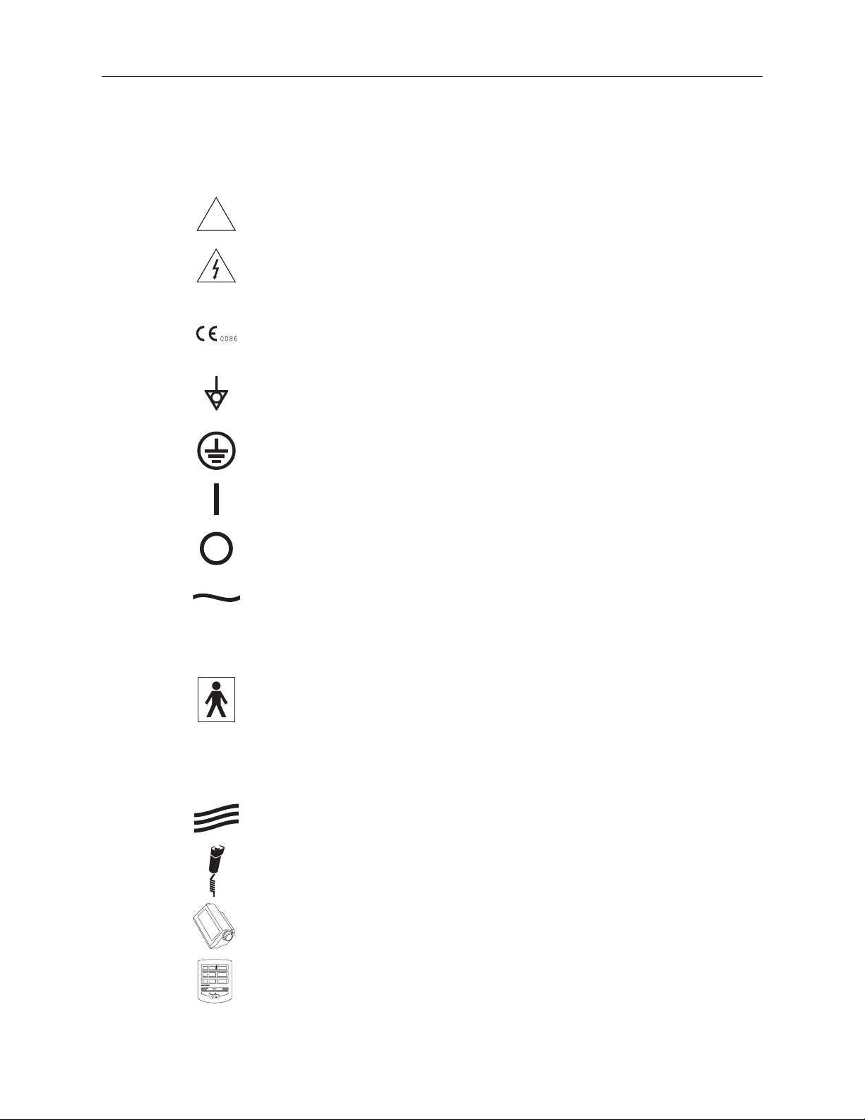
The following international symbols are used on the MEDRAD Vistron CT
Injector and throughout this manual.
!
Attention, consult accompanying instructions.
Attention, indicates hazardous voltages.
Indicates that this device conforms to the requirements of the European Medical Device Directive 93/42/EEC.
Identifies the equipotential ground.
Identifies the earth ground.
Identifies the ON switch position.
IPX1
CLASS 1
Identifies the OFF switch position.
Indicates alternating current.
Identifies the degree of protection against fluid as drip proof.
Identifies a type BF applied part complying with EN60601-1 standards.
Indicates the system is Class 1 medical equipment as defined by EN60601-1
standards
Identifies the connection on the Injector Head for the syringe heater.
Identifies connection of the remote Start/Hold Switch.
Identifies connection of the injector head cable.
Identifies connection of the remote monitor.
1 - 3
MEDRAD Vistron CT Injection System
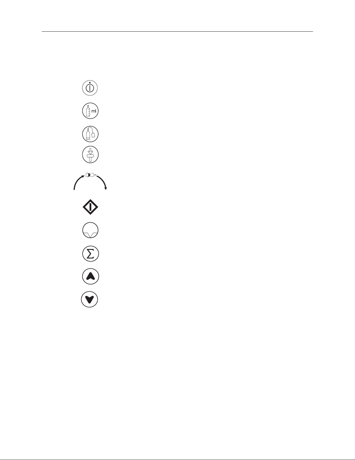
Symbols and
Descriptions (cont.)
Identifies the Standby key.
Identifies the Fill Select key.
Identifies the Autofill key.
Identifies the Retract key.
Identifies rotation direction on the Manual Knob for manually moving the piston. Clockwise is forward movement.
J302
Identifies the START key.
Identifies the HOLD key.
Identifies the SUMMARY key.
Identifies the UP Arrow key. Use to increase values when programming
Identifies the DOWN Arrow key. Use to decrease values when programming
Identifies the AutoLink connector.
1 - 4

Introduction
INTRODUCTION TO
WARNINGS / CAUTIONS
This manual contains important information about safe servicing of the
MEDRAD Vistron CT Injection System.
MEDRAD urges the service technician to read this manual carefully,
become familiar with the procedures and system functions that it
describes, and follow its recommendations to assure proper servicing
of the system.
Warning labels on the MEDRAD Vistron CT system or Warning statements in this manual preceeded by any of the following words and/or
symbols are of special significance:
WARNING: Indicates a potentially hazardous situation. If
!
not avoided, this could result in death or serious injury.
WARNING: Indicates electrical hazards which could result
in death or serious injury.
CAUTION: Indicates potential hazards or unsafe practices
!
which could cause product, system, or property damage.
NOTE: Indicates helpful information is being offered.
1 - 5

MEDRAD Vistron CT Injection System
WARNINGS Injury may result from exposure to hazardous voltages
existing within the system. The system should be opened
and serviced by qualified service personnel only. Disconnect
the system from line power before cleaning or attempting to
perform any maintenance.
Explosion hazard in the presence of flammables. Do not
!
!
use the system in the presence of anesthetic gases and
equipment.
Patient or operator injury can occur from use of worn
power cords or control cables. Examine power cords and
cables for cuts, frays, or any other visible damage. Do not
use the system if any of the cords or cables show signs of
damage. Any damaged or worn connection cables or power
cords should be replaced.
Patient or operator injury can occur from a falling injector head or pedestal. Do not move the head, pedestal, or
counterpoise system by pulling on the injector head or
cabling. Move the injector by grasping the center of the ped
estal or vertical arm on the counterpoise.
-
Unsafe operation may result from using improper acces-
!
sories and replacement parts. Use only accessories,
options, and parts provided by MEDRAD, and designed for
this system.
1 - 6

Introduction
CAUTIONS
Damage may occur as a result of failure to follow electro-
!
!
!
!
static discharge (ESD) protection practices. ESD protection
practices must be followed when servicing any component of
this system.
Damage could result from improperly handled components. Before touching any of the circuit cards in the system,
discharge yourself to grounded metal. If memory components
are to be shipped, place the components in conductive carriers
(as supplied through MEDRAD).
Damage can occur as a result of incorrect voltages. Check
the voltage and frequency marked on the back of the Power
Supply. Ensure that the outlet providing power to the injector
supplies a voltage, frequency, and volt-ampere rating within
the range specified on the unit.
Environmental damage may result from improper disposal
of system components or accessories. Electronic assem
blies contain potentially hazardous materials. Follow all local
regulations for the recycling or disposal of electronic assem
blies, or contact MEDRAD Service for assistance.
-
-
Damage can occur as a result of abrupt interruption or
!
!
!
!
application of supplies. To avoid damage to sensitive circuits
on the boards, disconnect the power cord before removing or
replacing PC boards.
Allow system temperature to stabilize before use. To avoid
damage to sensitive electronic circuits, allow the system to sta
bilize to room temperature before servicing when exposed to
extreme temperature changes.
Perform regular preventive maintenance. To ensure that
your MEDRAD Vistron CT System remains properly calibrated,
and that all primary and backup circuits are functioning prop
erly, regular preventive maintenance is recommended. An
annual preventive maintenance package is not included in the
new machine warranty. Contact your local MEDRAD Service
Representative for details.
Damage may result from improper or careless cleaning
methods. While cleaning any outside portion of the system,
avoid allowing any water to seep inside system components.
NOTE: All relevant guidelines for institutional, local, or
national safety recommendations related to cable routing
and installation should be followed.
-
-
1 - 7

MEDRAD Vistron CT Injection System
CAUTIONS
(cont.)
!
!
The injector may disarm or fail to operate when exposed to
high magnetic fields. Do not use radio transmitters, cellular
phones, or devices generating electrostatic discharge in the
vicinity of this system.
Condensation may cause electrical damage to the injector.
Do not use the injector immediately after it has been brought
indoors from extreme outside temperatures. Allow the injector
he stabilize at room temperature before use.
1 - 8

Maintenance and Checkout
Maintenance and
2
Checkout Procedures
This section contains recommended procedures for maintenance, and
an operational checkout of the
Routine maintenance and inspection will:
• Ensure continued performance of the injection system
• Reduce the possibility of equipment malfunction
MEDRAD Vistron CT Injection System.
Maintenance General maintenance of the MEDRAD Vistron CT injection system
should consist of four primary procedures: Inspection, cleaning, elec
trical leakage and ground continuity checks, and operational checkout. This section contains guidelines and recommended methods for
each of these procedures:
1. Inspection: This first step should encompass inspection of the
entire system, looking for obvious signs of damage, such as;
cracks in the housing, frayed or worn cables, and contrast media
spills which may have leaked into the system.
-
2. Cleaning: This procedure involves the thorough cleaning of all
system components to remove any deposits of contrast medium. If
any substances have leaked into any part of the system, the sub
assembly should be disassembled and thoroughly cleaned.
3. Electrical Leakage / Ground Continuity Checks: To ensure the
safety of the patient and hospital personnel in injection system
operations.
4. Operational Checkout: A complete functional performance checkout of the injection system.
-
2 - 1

MEDRAD Vistron CT Injection System
Recommended
Maintenance
Schedule
Your MEDRAD Vistron CT Injection System must be properly main-
tained to ensure that it is in peak operating condition. Your individual
maintenance system and schedule depends upon how your injection
system is used; the type of procedures performed, and frequency of
use. The following maintenance schedule is recommended for the
system:
Daily:
The piston rod should be thoroughly cleaned after each use. Before
use each day, the system should be cleaned and inspected, using the
procedures outlined in this section. Ensure that all system safety and
warning labels are in place and are legible.
Monthly:
Once a month, the entire system should be thoroughly inspected and
cleaned, and an Operational Checkout should be performed.
Annually:
Once per year, both Electrical Leakage and Ground Continuity checks
should be performed.
NOTE: Local regulations or hospital protocol may require
electrical leakage checks at more frequent inter
vals. If this applies, local regulations for leakage
must be followed.
-
MEDRAD also recommends that a complete system calibration and per-
formance checkout, by a qualified MEDRAD Service Representative or
authorized dealer, be performed once a year. Cont
Service, or your local
In the United States, Canada, and Europe, the MEDRAD Service
Department offers Preventive Maintenance Programs. These annual
programs greatly assist in maintaining accuracy and reliability, and
can also extend the life of the system. Contact
In Europe, contact your local MEDRAD office or your local authorized
dealer for further information. Refer to the Introduction Section of this
manual for address, telephone and FAX information.
NOTE: Failures which occur due to lack of proper mainte-
nance will not be covered under warranty.
MEDRAD office for complete details.
act MEDRAD Factory
MEDRAD for details.
2 - 2
Maintenance and Checkout
Inspection
Procedures
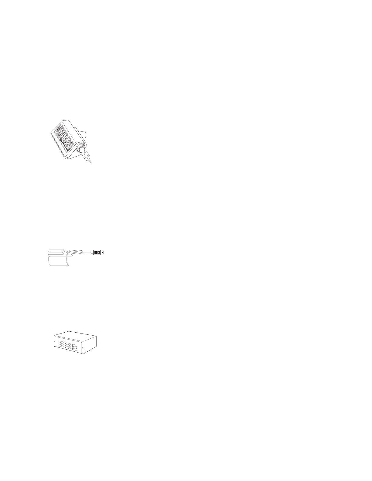
Injector Head /
Control Panel
The following procedures are recommended for daily inspection of all
components in the M
are detected, either repair the system, or call M
not use the system until the problem is corrected.
1. Inspect the housing for any damage or cracks that could allow
fluid to leak inside, or weaken the structural integrity of the unit.
2. Examine the handswitch and cable: Look for cuts, cracks, or worn
spots in the cable; look for cracks and loose parts in the switch
and housing. Ensure that the switch operates without sticking.
3. Inspect all cables connected to the unit: Look for cuts, cracks,
worn spots or other obvious damage to the cables. Ensure that all
connectors are properly seated.
4. Inspect for contrast media build-up in the syringe interface area.
Follow the cleaning procedures outlined in this section.
5. Verify proper operation of all LED displays.
EDRAD Vistron CT Injection system. If any defects
EDRAD for service. Do
Syringe Heater 1. Ensure that the device is warm to the touch.
2. Ensure that the LED indicator is not illuminated or flashing.
3. Inspect the cable and connector for cracks, worn areas, or other
obvious damage.
System Power
Console
1. Inspect all cables connected to the unit: Look for cuts, cracks, or
worn spots, or other obvious damage. Ensure that all connectors
are properly seated.
2 - 3
MEDRAD Vistron CT Injection System
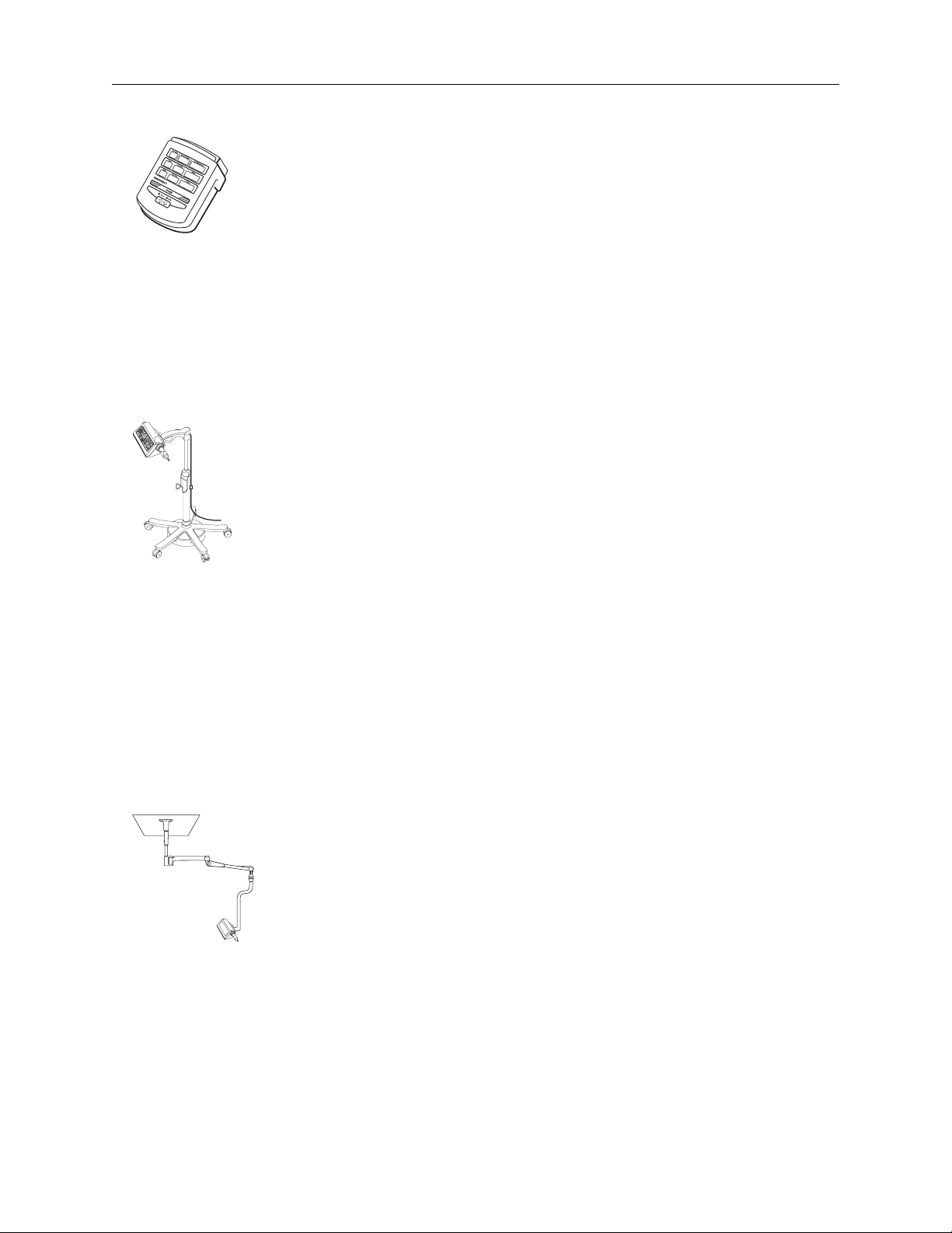
Remote Monitor 1. Inspect the housing for any damage or cracks that could allow
fluid to leak inside, or weaken the structural integrity of the unit.
2. Inspect the cable connected to the Remote Monitor: Look for cuts,
cracks, or worn spots in the cables; look for loose pins or strain
reliefs on the connectors. Ensure that the connector is properly
seated.
3. Inspect all parts of the wall mounting bracket for cracks or other
defects that would weaken the assembly. Ensure that the bracket
remains firmly attached to the wall.
Pedestal Mounts 1. Inspect the stand, base, and support arm for cracks and other
defects that could weaken the structure.
2. Ensure that all mounting bolts and screws are secure.
3. Ensure that the casters roll smoothly, with no binding or scraping.
CS Mounting
Systems
4. Ensure that all locking mechanisms on the casters are functional.
5. If applicable, verify that the vertical height adjustment of the column shaft moves freely, without binding or scraping.
6. Inspect the injector head pivots. The head and stand arm must
pivot freely. The injector head should rotate no more than 180
o
The stand pivot should not rotate more that 350
.
o
.
1. Inspect all parts of the arm and mounting system for cracks and
other defects that would weaken the system.
2. Ensure that the mounting system is securely assembled, with no
loose parts. The arm should be stable with the head installed.
3. Ensure that the arm moves smoothly in all directions, with no binding or scraping.
4. Verify that all cabling is tied back and does not interfere with the
movement of the supporting parts or the injector head.
2 - 4
NOTE: All relevant guidelines for institutional, local, or
national safety recommendations related to cable
routing and installation should be followed.

Maintenance and Checkout
Cleaning
Procedure
Deposits of contrast media can interfere with proper operation of the
Medrad Vistron CT Injection System. The following guidelines should be
followed when removing deposits, or cleaning any portion of the system.
WARNING: Injury may result from exposure to hazardous voltages existing within the system. Disconnect the
system from line power before cleaning or attempting to per
form any maintenance.
CAUTION: Improper or careless cleaning methods may
!
• If contrast medium has leaked inside any component of the system,
the effected subassembly should be disassembled and cleaned.
This cleaning procedure can be done in the field by trained Medrad
Service personnel, or returned to Medrad Factory Service. If the
cleaning will be performed in the field, do not disturb any internal wir
ing or components.
result in equipment damage. Do not soak or immerse any
part of the injection system in water. While cleaning any out
side portion of the system, avoid allowing any water to leak
inside system components.
-
-
-
• Care must be taken not to get water or cleaning solutions inside any
system components. Do not use strong industrial cleaning agents or
solvents such as acetone. Warm water and a mild disinfectant such
as antibacterial hand soap are all that is required.
• To clean the syringe interface area of the injector head, fully retract
the piston. Using a paper towel moistened with warm water or a mild
disinfectant, gently wipe the inner syringe installation area. Do not
insert any sharp instruments into this area during the cleaning pro
cess.
• The 100 ml syringe adaptor plate and piston extensions may be
removed and soaked or submerged in water or mild cleaning solu
tion. Ensure that the adaptor plate is completely dry before installing
onto the injector head.
• Check all System Safety and Warning Labels for legibility. Ensure
that the labels are not damaged or missing.
WARNING: Injury may result from exposure to hazardous voltages existing within the system. Ensure that the
system is completely dry before connecting to the power
source and applying power.
-
-
2 - 5

MEDRAD Vistron CT Injection System
Electrical
Leakage
Check
To ensure safe operation of the Medrad Vistron CT Injection System,
an electrical leakage check must be part of regular maintenance.
Use a commercial leakage tester such as one of the following:
MANUFACTURER MODEL
Bio-Tek Instruments, Inc. Model 601 PRO
Electrical Safety Analyzer
Bender Unimet 1000 ST
Bapco IEC601L
1. With the AC ground open, power applied, and the line at normal,
leakage should be less than 100 micro amps at 110V, or 300 micro
amps at 220V.
2. With the AC ground open, power applied and the line reversed,
leakage should be less than 100 micro amps at 110V, or 300 micro
amps at 220V.
3. Disconnect the leakage test device.
Ground
Continuity
Check
Operational
Checkout
A ground continuity check must also be part of regular maintenance of
the Medrad Vistron CT system.
1. Disconnect the system from the power source.
2. Using an ohm meter, measure the resistance between the ground
terminal on the power cord and the Power Supply housing. The
resistance measured must be less than 0.2 ohms.
A basic functional checkout of the Medrad Vistron CT Injection System should be included as part of regular maintenance. Verifying
proper operation of the injection system will help in detection of any
problems that may not be noticed in day to day operation. The follow
ing procedure represents a suggested series of activities which
encompass typical operation of the system. Read the following proce
dure carefully before beginning the checkout. If problems are
detected, refer to the General Troubleshooting Procedures found in
Section 3.
NOTE: Any problems detected during this or any other
procedure should be corrected before using the
injection system in patient procedures.
-
-
2 - 6

Maintenance and Checkout
System Labels Ensure that all system safety and warning labels are in place and legible.
Power Up Apply power to the injector. Verify that the injector beeps and that all indi-
cators on the injector head and remote monitor illuminate. After the injector
completes the diagnostic tests, use the Enable key and the Forward/
Reverse motion controls to fully advance and reverse the piston.
Programming 1. Enter the following protocol. Verify that all of the increment/decrement
keys function properly.
Flow Rate Volume
Phase 1: 9.9 ml/sec 40 ml
Phase 2: 6.5 30
Phase 3: 3.0 20
Phase 4: 1.0 10
Pressure Limit: 200 psi
2. Press the Summary key to verify that the total and maximum values
display on the control panel.
3. Install a 125 or 200 ml Qwik-Fit syringe.
4. Fully advance the piston plunger.
5. Use Fill Select to select 100 ml.
6. Use the Autofill key to reverse the piston plunger to the 100 ml posi-
tion.
7. ARM in the Single Injection mode. Start the injection by pressing the
Start key on the injector head.
8. Verify that the Scan Delay timer beeps during the last 10 seconds of
the countdown, and when the countdown completes.
9. During one of the phases, press the Hold key to pause the injection for
at least 10 seconds. Press the Hold key again to resume the injection.
10. Verify that the injection progresses and completes normally.
11. Remove the syringe and press the Retract key to fully retract the piston.
12. Use the Disarm/Reset key to delete the entire protocol.
2 - 7

MEDRAD Vistron CT Injection System
13. Enter the following protocol (with a Scan Delay of 15 seconds):
Phase 1: 2.0 ml/sec 45 ml
Pressure Limit: 200 psi
14. Reinstall the syringe and arm in the Multi Injection mode.
15. Press the remote Start switch to start the injection.
16. Verify that the injection completes successfully and that the injector
remains armed.
17. Use the remote monitor the start another injection. Verify that the
Scan Delay timer on the remote monitor beeps during the last 10
seconds of the countdown and when the countdown is complete.
18. Verify that the injection completes successfully, and that the injector remains armed.
Flow Rate Volume
19. Disarm the injector by pressing the Disarm key on the
remote monitor.
20. Remove power from the unit.
AutoLink Check 1. Enter an injection protocol in which the injector will start and stop
the CT scanner. Verify that the scanner will start and stop in
response to the injector scanner relay signal.
2. Enter an injection protocol in which the CT scanner will start and
disarm the injector. Verify that the injector will start and disarm in
response to the AutoLink control on the CT scanner.
2 - 8

3 Troubleshooting
Troubleshooting
System Malfunction
Codes
General
Troubleshooting
Guidelines
Conditions can occur which will prevent the injection system from being
armed, or even interrupt an injection that is in progress. These conditions
may be operator induced or caused by a system malfunction. Error Codes
which inform the user of these conditions are displayed on the control
panel.
Consider the following guidelines before troubleshooting any condition.
These guidelines may help in resolving the condition quickly: Remember,
try the simple things first.
CAUTION: Damage may occur as a result of failure to follow electrostatic discharge (ESD) protection practices.
!
ESD protection practices must be followed when servicing any
component of this system.
CAUTION: Damage could result from improperly handled
components. Before touching any of the circuit cards in the
!
system, discharge yourself to grounded metal. If memory com
ponents are to be shipped, place the components in conductive
carriers (as supplied through MEDRAD).
CAUTION: Disconnect the power cord before removing or
replacing PC boards. Sensitive circuits on the boards can be
!
damaged by abrupt interruption or application of supplies.
-
• Try removing power for one minute. Allow the system to reset completely, then reapply power and retry. The condition could be intermittent, or caused by a voltage transient. If the condition persists,
continue troubleshooting.
• To verify the existence of a condition, attempt to re-create the problem.
Follow the Checkout Procedure outlined in Section 2 of this manual to
check for proper (or improper) operation of the system.
• Some faults can be caused by a noisy electrical environment. If these
conditions persist, contact MEDRAD Factory Service* for further assis
tance.
* Indicates contact MEDRAD Factory Service or an Authorized Dealer.
3 - 1
-

MEDRAD Vistron CT Injection System
Message Codes [U] Message Codes
Identify conditions which require attention. These messages will clear
the control panel within 5 seconds (press any key to clear the message
after 2 seconds). The [U] code list is on page 3 - 3.
[P] Message Codes
Identify conditions which require action. These messages will clear the
control panel when the operator responds to the condition which caused
the message to appear. The [P] code list is on page 3 - 4.
[d] Message Codes
Identify conditions which cause the system to disarm. These messages
will clear the control panel within 5 seconds (press any key to clear the
message after 2 seconds) when the condition which causes them to
appear is corrected. The [d] code list is on page 3 - 4.
[C] Message Codes
identify errors that require additional attention. These errors fall into two
categories: errors that may be operator correctable, and errors that indi
cate the activation of an injector safety back-up system. The [C] message code list and troubleshooting instructions begin on page 3 - 5.
-
3 - 2

Troubleshooting
[U] Codes Display Description
U103 Cannot continue with injector head operation - Invalid
piston or manual knob movement detected.
U110 Cannot arm - Total Volume of the protocol exceeds syringe
capacity. Attach a larger syringe or adjust volume.
U121 Cannot continue injector head operation - Syringe or
adapter is not fully engaged. This message will also appear
if the Retract key is pressed while a syringe is engaged.
U122 Cannot continue injector head operation - Syringe or
adapter plate has been installed.
U131 Cannot activate Autofill. Press Enable/Forward Motion
control or use manual knob to extend piston fully (0 - 1 ml
syringe volume).
U132 100 ml Systems: Cannot activate Autofill - 100 ml adapter
is attached.
Non-100 ml systems: A system failure occurred. Disconnect the patient and contact MEDRAD Service*.
U133 Cannot activate Autofill - The system has detected a pre-
filled syringe attached.
U141 Cannot continue with injector head operation - Operator
pressed a control panel key or Start switch.
U153 Cannot Arm - ISI Injector Start Input/Disarm Control is
active (J302 pins 20 and 25 are shorted).
U161 Cannot program Duration before programming Volume.
U162 Cannot change phases with an invalid or incomplete phase.
U171 Cannot arm with an incomplete or invalid phase.
U172 Cannot arm - Scroll to highest phase before proceeding.
U175 Cannot arm - Syringe volume is 0 ml.
U321 Arming - System diagnostics in progress. Press any key to
interrupt process.
3 - 3

MEDRAD Vistron CT Injection System
[P] Codes Display Description
P100 Is air expelled from syringe and fluid path? Press
Disarm/Reset key to cancel or Arm/Yes to continue.
P123 100 ml syringe adapter is detected. Press Inject Mode key
to confirm that an adapter plate has been installed.
(100 ml configurations only)
P124 100 ml syringe adapter is not detected. Press Inject Mode
key to confirm that adapter plate has been removed.
(100 ml configurations only)
P123, 124 (Non-100 ml configurations)
A system failure occurred. Disconnect patient and contact
MEDRAD Service.
P125 Cannot continue self diagnostics with syringe attached.
Remove syringe to continue.
P151 AutoLink available? Press Inject Mode key to confirm that
the system is interfaced with the scanner.
P152 AutoLink not available? Press Inject Mode key to confirm
that the system is not interfaced with the scanner.
[d] Codes Display Description
d101 System disarmed - Control panel key or Disarm/Reset key
was pressed.
d108 System disarmed - Injector stalled.
d115 System disarmed - Hold time exceeded 10 minutes.
3 - 4
d116 System disarmed - Start switch was inserted or removed.
d117 System disarmed - Manual knob was rotated.
d118 System disarmed - Syringe or adapter was detached.
d119 System disarmed - Backlash timer expired. Syringe pres-
sure was greater than backlash pressure.
d120 System disarmed - AutoLink Start/Disarm input (J302 pins
20 and 25) opened during an injection.

Troubleshooting
[C] Codes
C500 Check Remote Start/Hold Switch
This error code typically indicates a problem with the remote start
switch (VHS 600) connected at J102. If a remote start switch is not
present, contact MEDRAD Service. If one is present, take the following
steps to attempt to return the injector to service:
1. Check the remote start switch connection at the head to assure the
connector is fully seated. If the connection is loose, remove and
reattach the connector.
2. Press the Standby key on the injector head to reset the system.
3. Disconnect the patient and perform a trial injection using the
remote Start/Hold switch. If the system performs correctly, return
the system to use.
4. If the error code reappears, remove the Start/Hold switch from the
injector head.
5. Press the Standby key, and perform another trial injection, using
the Start/Hold switch on the injector head. If the system performs
correctly, contact MEDRAD Service for a replacement remote
Start/Hold switch.
6. If the error persists, contact MEDRAD Service.
C510 Check Remote Monitor
This error code typically indicates a problem with the Remote Monitor
(VRM 600). If a Remote Monitor is not present, contact MEDRAD Ser
vice*. If a Remote Monitor is present, take the following steps to
attempt to return the injector to operating status:
1. Check the remote monitor connection at the system power console
to assure the connector is fully seated. If the connection is loose,
turn off the AC power at the system power console, remove and
reattach the connector.
2. Turn on the AC power to the system, or press the Standby key on
the injector head.
-
3. Disconnect the patient and perform a trial injection using the Start/
Hold key on the remote monitor. Observe the remote monitor dis
plays during the injection. If the system performs correctly, return
the system to use.
-
3 - 5

MEDRAD Vistron CT Injection System
4. If the error code reappears, turn off the AC power and disconnect
the remote monitor from the system power console.
5. Apply the AC power and perform another trial injection using the
Start/Hold key on the injector head. If the system performs
correctly, contact MEDRAD Service* for a replacement remote
monitor.
6. If the error persists, contact MEDRAD Service*.
Error codes C520, C530 and C540 indicate that the safety back-up
subsystems in the Vistron CT injector have detected a pressure
(C520), volume (C530), or flow rate (C540) in excess of the specifica
tion limits for the programmed value. Disconnect the patient immediately and examine the patient for injury. Contact MEDRAD Service*
before using the system again.
C520 System Pressure Exceeded Pressure Limit
-
This may occur as a result of injecting into a blockage or a small catheter/needle with the maximum pressure limit selected. Check the fluid
path for blockages, then press the Standby key to restart the injector.
If no blockage exists, reduce the flow rate or pressure limit according
to the instructions of the physician.
C530 Injected Volume Exceeded Programmed Value
C540 Flow Rate Exceeded Programmed Value
C560 Head Overlay Failure Detected
This error indicates that an overlay key press was detected during
power-up or arming when none should have been present. This may
have been due to an accidental key press from the operator, or a fault
in the overlay itself. Restart the system by pressing the Standby key,
and do not press any keys until self diagnostics are complete. If the
error code is displayed again, Contact MEDRAD Service*.
3 - 6

Troubleshooting
C570 A Failure Occurred in the AutoLink Interface
This error may occur when the interface cable and circuit are being
tested. This condition can be caused by a loose or improper connec
tion. Verify the connection of the cable at the power supply and scanner. If all cable connections are secure and this code persists,
disconnect the interface cable and contact MEDRAD Service. The
injection system will function, but AutoLink will not be operational.
C599 System Error, Call MEDRAD Service*
A C599 error indicates that a failure has occurred within the system.
Disconnect the patient, and contact MEDRAD Service*.
OTHER MALFUNCTIONS
If after pressing the Standby key to power up the system the injector
head or remote monitor displays are blank:
-
• Check the power cord, all cables, and connections.
• Verify that the Main Power switch on the System Power
Console is in the ON position
• If the problem persists, call MEDRAD Service*.
Failure of individual displays or keys, damage to system components,
or any other misoperation should also be brought to the attention of
MEDRAD Service*.
3 - 7
 Loading...