

Page 1
PRELIMINARY
VerisTM 8600
Vital Signs Monitor
Operation Manual
3010796 Revision 0
Date 10/04
Page i
Page 2

VerisTM 8600
Operation Manual
Copyright 2004, MEDRAD Inc. All rights reserved.
Reproduction of this manual is str ictly prohibited
without express written consent of MEDRAD, Inc.
For more information about MEDRAD products
and services, please visit www.medrad.com
Page ii
Page 3

Contents
Contents................................................................................................................iii
In Case of Emergency Contact.............................................................................xi
MEDRAD Subsidiaries.................. ...................................................................xi
International Offices.........................................................................................xi
Symbols.............................................................................................................. xiii
Regulatory Symbols.......................................................................................xiii
Safety Symbols...................................... ......................... ......................... ...... xiii
System Symbols............................................................................................xiv
Port Symbols.................................................................................................xiv
Miscellaneous Symbo l s................................. ......................... .......................xiv
Safety ...................................................................................................................xv
Definitions.......................................................................................................xv
Warnings.........................................................................................................xv
Cautions........................................................................................................xvii
Introduction .........................................................................................................xxi
Description.....................................................................................................xxi
Intended Use .................................................................................................xxi
Clinical Use...................................................................................................xx i i
Section 1 - Panel Features
Front Panel ................................................................................................................... 1-1
Menu Knob..... .................................................................................................... 1-2
Color Display...................................................................................................... 1-2
Water Trap and Gas Sampling Connection .......................................................1-2
Left Side Panel (Main Monitor) .....................................................................................1-3
Communication Port (Main Monitor)........................................... .................................. 1-4
Main Monitor Base Connections...................................................................................1-5
Chassis Ground .................................................................................................1-5
DC Connection...................................................................................................1-5
Exhaust Port....................................................................................................... 1-5
Air Intake Port ....................................................................................................1-5
Remote Display..................................................................................................1-6
Printer...........................................................................................................................1-8
Accessory Tray.............................................................................................................1-8
Veris 8600 Configurations........................................................................... ....... .. .... .. .. .1-9
Section 2 - Monitor Setup
Battery Power............................................... ......................... .......................... ............. 2-1
Charging the Battery ..........................................................................................2-1
Battery Indicator s....................... ......................... ......................... ......................2-2
System Start and Auto-calibration ................................................................................2-3
Sensor and Probe Messages.............................................................................2-4
Gas Calibration.................................................................................................. 2-4
Screen Display and Interface........................................................................................ 2-5
Waveform Slots..................................................................................................2-6
Numerical Parameter Boxes................................... ......................... ..................2-9
Main Menu....................................................................................................... 2-11
Alarm and Message Areas...............................................................................2-12
System Status Box...........................................................................................2-12
Patient Information and Clock.......................................................................... 2-12
Keypad........................................................................................................................2-13
Softkey Functions (Main Menu).................................................................................. 2-14
Changing Settings............................................................................................2-14
Saved Setting Profile s............................................... .......................... ............. 2-15
Page iii
Page 4

MEDRAD
ALARMS Softkey............................ .......................... ......................... ......................... .2-16
PARAMS Softkey (Physiological Parameters)........... ......................... ........................2-21
DISPLAY Softkey ........................................................................................................2-27
ADM/DIS Softkey (Admit/Discharge)...........................................................................2-31
CONFIG Softkey (System Configuration)....................................................................2-34
PRINT Softkey.............................................................................................................2-37
Default Settings.................................................................... ......................... ..............2-38
Veris
8600
Primary ALARMS Window................................................................................2-17
Invasive Blood Pressure Alarm Settings ..........................................................2-18
Agent Gas Alarms ............................................................................................2-19
Primary PARAMS Window ...............................................................................2-21
, Respiration, Temperat u re Menu............. ......................... ......................2-24
SpO
2
Gas Settings.................... ......................... .......................... ......................... .....2-25
Waveform Description......................................................................................2-27
Double Height Slots........................................................................ .. .. .. ..... .. .. .. .2-28
Cascaded Slots............................................... .................................................2-29
Gain and Sweep...............................................................................................2-30
Admitting and Discharging Patients..................................................................2-31
Adult/Pediatric/Neonatal (Patient Size) ............................................................2-32
Patient Information ...........................................................................................2-32
Procedure for Admitting a Patient.....................................................................2-32
Procedure for Discharging a Patient.................................................................2-33
Password Protection.........................................................................................2-35
Date Format......................................................................................................2-35
Time/Date Setting................................. ................................................... .........2-35
Freeze Timeout................................................. ......................... ......................2-35
Standby Timeout ..............................................................................................2-35
Standby Tone...................................................................................................2-35
Alarm Tone Warning.........................................................................................2-35
Print Device............... .................................................. .....................................2-35
Language Settings............................................. .. .... .. .. .. .. ..... .. .. .... .. .. .. .. ..... .. .. .. .2-36
Factory Defaults............................................ .................................................. .2-38
Section 3 - Alarms and Messages
Alarm Description................................ .................................................. ........................3-1
Remote Display Alarms.................... ..................................................................3-1
Audible Alarms.............................................. ......................... ......................... ...3-1
Visible Alarms....................................................................................... ..............3-2
Waveforms Frozen.............................................................................................3-2
Alert Icons.............................. .......................... ......................... ......................... .3-3
Special Alarm Conditions..............................................................................................3- 3
Alarms at Start Up.......................... ......................... ......................... ..................3-3
Alarm Silence.................... ......................... .......................... ......................... .....3-3
Alarms tone warning (Warning Tone)............................................................ .... .3-4
Alarm Volume.................... ......................... .......................... ......................... .....3-4
Minimum Volume Auto-Reset............................................... ......................... .....3-4
Standby Mode ....................................................................................................3-5
Agent Standby Mode............................................................................ ....... .... .. .3-5
Standby Mode Timeout ......................................................................................3-5
Low Limit Auto-Reset................................................................................3-5
SpO
2
SpO
Low Limit Off Alarm..................................................................................3-5
Triggering an Alarm.......................................................................................................3-6
Alarms Testing..................... ......................... .................................................. ..............3-6
2
Page iv
Page 5

Contents
Alarm Message List ...................................................................................................... 3-7
Shared Source Alarms.......................................... ......................... ....................3-7
ECG Alarms.......................................................................................................3-7
Alarms......................................................................................................3-7
SpO
2
Temperature Alarms .......................................................................................... 3-8
NIBP Alarms....................................................................................................... 3-9
IBP Alarms....................................................................................................... 3-10
Capnometry (CO
Agent Gas Alarms and Messages....................................................................3-11
Oxygen Monitoring (O
System Alerts.............................................................................................................. 3-14
) Alarms and Messages....................................................... 3-11
2
) Alarms.......................................................................3-13
2
Section 4 - Trends
Description.................................................................................................................... 4-1
Trend Interval..................................................................................................... 4-1
Capacity.............................................................................................................4-1
Trend Screen Update............................................................... .... .... ......... .. .... ...4-1
Trend Setup.................................................................................... .. .... .. .. .. ..... .. .... .. .. .. .4-2
Graphical Trends .................................................................................. .. .... ......... .... .... .4-4
Scrolling the Graph ............................................................................................4-4
Interruption Due to Power Cycling or Standby Mode.........................................4-4
Graphical Trend Display.....................................................................................4-5
Tabular Trends....................................................................................................... .... ...4-6
Tabular Trend Markers.......................................................................................4-6
Trend Messages ................................................................................................4-6
Data Format................ ..................................................... ......................... ......... 4-7
Clearing the Memory...... ......................... .................................................. ..................4-10
Section 5 - ECG
Theory of Operation...................................................................................................... 5-1
Heart Rate................................ ......................... .................................................5-1
ECG Measurement............................................................................................5-1
ECG module....................................................................................................... 5-2
Gating Signals....................................................................................................5-3
ECG Monitoring (Electrocardiogram)............. ............................................................... 5-4
Protection...........................................................................................................5-6
ECG Performance..............................................................................................5-6
Electrode Selection............................................................................................5-6
ECG Module Interface .................................................................................................. 5-7
ECG Module Ports And Switches ......................................................................5-7
Battery Condition................................................................................................ 5-8
Charging the Battery ..........................................................................................5-9
ECG Monitoring..........................................................................................................5-11
Patient Preparation ..........................................................................................5-11
Lead Placement. ..............................................................................................5-12
Connecting Patient to the Monitor....................................................................5-14
Completion of ECG Monitori n g................... ..................................................... 5-15
ECG Auto Lead Switching .......................................................................................... 5-16
Primary Lead . . .................................................................................................. 5-16
Alternate Lead Priority......................................................................................5-17
Gating Interface ..........................................................................................................5-18
Page v
Page 6

MEDRAD
Veris
8600
Section 6 - NIBP
Theory of Operation ................................................................... ....... .... .... .. .... ....... .... ...6-1
Heart Rate..........................................................................................................6-1
Comfort Cuff™ Technology................................................................................6-1
Description of NIBP Meas u rement.................... .................................................6-1
NIBP Clinical Testing and Accuracy...................................................................6-1
Cuff Inflation and Pressure Protection................................................................6-2
NIBP Monitoring ............................................................................................................6-3
Selecting Cuffs and Hoses............................................................................................6-5
Placing the NIBP Cuff....................................................................................................6-6
Procedure......................................................................................................................6-7
Taking NIBP Measurement s............................................ ......................... ....................6-8
Section 7 - SpO
Theory of Operation ................................................................... ....... .... .... .. .... ....... .... ...7-1
Heart Rate..........................................................................................................7-1
Definition.............................................................................................................7-1
DOX™ Digital Oximetry.............. .................................................... ....................7-1
Method................................................................................................................7-1
SpO
Clinical Testing and Accuracy...................................................................7-2
2
Gating Signals.................................................................................. .. .. ..... .. .. .. .. .7-2
Monitoring Procedures (Pulse Oximetry).............................................................7-3
SpO
2
Attaching the Probe to the Monitor................................................................................7-4
Attaching the Probe to the Patient.................................................................................7- 4
Finger Probe Application for Adults....................................................................7-6
Neonate Probe Placement .................................................................................7-7
Peripheral Gating ..............................................................................................7-10
SpO
2
2
Section 8 - IBP
Theory of Operation ................................................................... ....... .... .... .. .... ....... .... ...8-1
Heart Rate..........................................................................................................8-1
Method of Measurement.....................................................................................8-1
IBP Clinical Testing and Accuracy......................................................................8-1
IBP Monitoring...............................................................................................................8-2
Invasive Blood Pressure Transducers and Interface Cables ........................................ 8- 3
IBP Interface Cable ............................................................................................8-3
IBP Monitoring Procedure.............................................................................................8-5
IBP Safety...........................................................................................................8-6
Setup and User Calibration .......................................................... .... .. ....... .... .. ...8-6
Zero Calibration (Quic k).....................................................................................8-8
Clinical Use and Arterial Waveforms..................................................................8-9
Section 9 - Temperature
Theory of Operation ................................................................... ....... .... .... .. .... ....... .... ...9-1
Temperature Monitoring Procedures.............................................................................9-2
Directions for Use with Skin Surface Probe..................................................................9-4
Preparing the Equipment....................................................................................9-4
Attaching the Temperature Probe to the Patient................................................9-4
Page vi
Page 7

Section 10 - Anesthetic Agents
Contents
Theory of Operations..................................................................................................10-1
Integrated CO
and Agent Gas Detector ......................................................... 10-1
2
Agent Gas Measurement ............................................................... ........... .... ...10-1
Gas Monitoring Procedures........................................................................................10-2
Sampling Circuit Connections.......................................................................... 10-2
Gas Monitoring Safety...................................................................................... 10-3
Water Trap................ ......................... ................................................... ........... 10-4
Sampling Devices...................... ......................................................................10-5
Intubated Patients............................................................................................10-5
Calibration and Startup .................................................................................... 10-6
Procedure for Gas Monitoring.......................................................................... 10-7
Occlusions........................................................................................................10-7
Anesthetic Gas Exhaust Recovery...................................................................10-7
Section 11 - CO2, O2, and N2O
Theory of Operation....................................................................................................11-1
Respiration.......................................................................................................11-1
Capnometry (Measurement of CO
Measuring Oxygen (O
Monitoring Procedure..........................................................................................11-4
CO
2
Monitoring Procedures ..........................................................................................11-5
O
2
Interfering Gasses for O
O Monitoring.............. .................................................. ......................... ..................11-5
N
2
)...................................................................................11-2
2
.................................................................................11-5
2
)................................................................11-1
2
Section 12 - Printing and Data Ports
Description.................................................................................................................. 12-1
Snapshot Size..................................................................................................12-1
History Size......................................................................................................12-1
Safety..........................................................................................................................12-1
Print Modes................................................... .... ......... .... .. .... ......... .... .. .... .... ......... .... .. .12-2
Demand Print................ ......................... ................................................... ....... 12-2
Continuous Print............................................................................................ ...12-2
Alarm Print...................... ................................................... ......................... ..... 12-2
BP Print.................................. .................................................. ........................12-2
Interval Print.....................................................................................................12-2
Freeze Print......................................................................................................12-2
Trend Print ....................................... .. .. ....... .... .. .. .... .. ....... .. .... .. .... .. .. ....... .... .. ...12-3
Print Formats............................................................. ......................... ........................12-4
Tabular Printing............................................................................................. .. .12-4
Graphical Printing................................................................. .... .. .. .... ....... .. .... .. .12-4
Changing Printer Paper ..............................................................................................12-7
Data Output Ports........................... ......................... .................................................. .12-9
COM1 Port.......................................................................................................12-9
COM2 Port.....................................................................................................12-11
Video Port................................................................................................................. 12-11
CSV Data Format............................................................. ......................... ................12-12
Page vii
Page 8

MEDRAD
Veris
8600
Appendix A: Maintenance
Cleaning and Disinfecting........................................................................ .. .... .. ....... .... ..A-1
Pulse Oximeter Sensors....................................................................................A-2
Blood Pressure Cuffs......................................................................................... A-2
Temperature...................................................................................................... A-3
Accidental Wettin g. ................................................... .................................................. ..A-4
Annual Safety Tests..................................................................................................... A-5
System Testing............ .................................................... .......................... ........ A-5
Service Checks...................................................... ......................... ................... A-5
Maintenance Schedule . ................................................................................................ A-6
Long-Term Storage...................................................................................................... A-7
Disposal........................................................................................................................A-7
Appendix B: Unit and Configuration Defaults
Restoring the Unit Default Profile.......................... ........................................ ............... B-1
Default Settings.................................................................... ......................... ............... B-1
Unit Default Settings.......................................................................................... B-1
Configuration Default Settings........................................................................... B-3
Configuration Settings for Unit Defaults ....................................................................... B-5
PARAMS Menu Settings ................................................................................... B-5
PRINT Menu Settings........................................................................................ B-6
DISPLAY Menu Settings ...................................................................................B-6
ALARMS Menu Settings.................................................................................... B-7
Other Alarm Settings ....................................................................................... B-11
Appendix C: Specifications
ECG..............................................................................................................................C-1
ECG System................................................................ ......................... ............. C-1
ECG Module.................................................................. ....... .. .... .. .. .... .. ....... .. .. ..C-1
Leadset..............................................................................................................C-1
ECG Module Charger................................................................................ .. .... ..C-2
............................................................................................................................ C-2
SpO
2
Heart Rate....................................................................................................................C-2
Gating...........................................................................................................................C-3
Temperature................................................................................................................. C-3
NIBP.............................................................................................................................C-3
Invasive Blood Pressure............................................................................................... C-4
Transducer........................................................................................................C-4
Capnometry (CO
CO
Respiration...........................................................................................................C-4
2
Halogenated Agents.....................................................................................................C-5
Nitrous Oxide (N
Oxygen Monitoring (O
Pneumatics...................................................................................................................C-6
Alarms..........................................................................................................................C-6
Trend Reports .......................... .. .. .. .. ..... .. .. .. .. .. .. .. .. ..... .. .... .. .. .. .. .. ..... .. .. .. .. .. .. .. .. ..... .... .. ..C-7
Printer (Remote Displa y onl y) ..................... .................................................................C-7
Controls........................................................................................................................C-7
System Outputs (Remote Disp la y Only)........................... ............................................C-7
Environmental..............................................................................................................C-7
Mechanical/Electrical....................................................................................................C-8
Remote Display................. ................................................................................ C-8
Main Monitor.............. .................................................. ......................................C-8
) .......................................................................................................C-4
2
O).....................................................................................................C-6
2
) ...............................................................................................C-6
2
Page viii
Page 9

Contents
Appendix D: Accessories
ECG Accessories..........................................................................................................D-1
ECG Module.......................................................................................................D-1
ECG Electrode Accessories...............................................................................D -1
ECG Gating Accessories ...................................................................................D-1
SpO
Accessories.........................................................................................................D-1
2
Probes ......................................................................................................D-1
SpO
2
Peripheral Gating Accessories.................................................................D-1
SpO
NIBP Accessories.........................................................................................................D-2
IBP Accessories............................................................................................................D-2
Temperature Accessories.............................................................................................D-2
Agent Accessories ........................................................................................................D-2
Miscellaneous Accessories................................................................................ ...........D-3
Publications...................................................................................................................D-3
2
Reusable Cuffs...................................................................................................D-2
Disposable Cuffs................................................................................................D-2
Operation Manuals.............................................................................................D-3
Help Cards.........................................................................................................D-3
Installation and Service......................................................................................D-3
Appendix E: Troubleshooting
General Troubleshooting ............................................... .. .... .. ....... .... .. .... .. .. ......... .. .... .. .E-1
Troubleshooting Table......... .... .. ......... .... .. .... .... ....... .... .. .... .... ....... .... .... .. .... ....... .... .... .. .E-1
Appendix F: IBP Transducer Specifications
IBP Specifications..............................................................................................F-1
Transducer Specifications................ ......................... .........................................F-1
Transducer Cables............................................................... ......................... ..... F-1
Compliance........................................................................................................F-1
Defibrillation Protection...................................................................................... F-1
High Frequency Interference..............................................................................F-2
Appendix G: Wireless Communication
Wireless Network Communication Interface................................................................ G-1
Operation..................................................................................................................... G-1
Appendix H: Battery and Fuse Specifications
Battery Specifications ................................................................... ......................... .......H-1
Main Monitor Batt eries .......................................................................................H-1
Fuse Specification s................................................ ......................... ......................... .....H-2
Remote Display Fuses.......................................................................................H-2
Main Monitor Fuses............................................................................................H-2
Power Supply Fuses ..........................................................................................H-2
Fuse Removal/Replace men t.................................................. .......................... .............H-3
Remote Display..................................................................................................H-3
Power Supply.....................................................................................................H-4
Page ix
Page 10

This page intentionally left blank.
Page 11

In Case of Emergency
Contact
MEDRAD, Inc. Corporate Office MEDRAD, Inc. Service Repair
One Medrad Drive One Medrad Drive
Indianola, PA 15051-0780 USA Indianola, PA 15051-0780 USA
Telepho ne: 1 ( 412 ) 767-2 400 Telepho ne: 1 ( 412 ) 7 67-24 00
FAX: 1 (412) 767-4128 FAX: 1 (412) 767-4126
OTHER: 1 (800) 633-7231 OTHER: 1 (800) 633-7237
MEDRAD Subsidiaries
International Offices
Imaxeon Pty. Ltd.
Rydalmere Metro Centre (Alternate address:)
Unit 2, 38-46 Sout h Str ee t P.O. Box 150
Rydalmere NSW 2116 Rydalmere BC
Australia NSW 1701
Telepho ne: +6 1 2 88 45 499 9 Sydney, Australia
FAX: +61 2 8845 4998
MEDRAD Europe B.V. Nihon MEDRAD K.K.
P.O. Box 205 9F Central Shin-Osaka Bl dg.
6190 AE Beek 4-5-36, Miyahara
The Netherland s Yodogawa-ku
Telepho ne: +3 1 ( 0) 43- 35 85 600 Osaka 532-0003, Japan
FAX: +31 (0) 43-3 656 59 8 Telepho ne: +8 1 (0 ) 6-6 35 0- 068 0
(Visiting MEBV address:) FAX: +81 (0) 6-6398- 06 70
Horsterweg 24
6199 AC Maastricht Air p ort
The Netherland s
MEDRAD do Brasil ltda. Mediwest Denmark ApS
Av. Fagundes Filho, 191 - Naverland 2
conjuntos 51 a 54 e 57 2600 Glostrup
Ed. Houston Office Cen te r Denmark
Vila Monte Alegre Telepho ne: +4 5 38- 1 6 16 16
04304-000 - São Paulo - SP FAX: +45 38-16 16 46
Telepho ne: +( 11 ) 5 079 -650 0
FAX: +(11) 5584-89 51
MEDRAD Middle East & Africa
92 Al Lasilky Street
New Maadi Ca i r o
Egypt
E-mail: Medrad_ME&A@medrad.com
(If contacti ng Andre directly, please
phone or fax)
+00.20.2.754.88.29
Page xi
Page 12

MEDRAD
MEDRAD France S.a.r.l. MEDRAD, Inc. (Asia)
8, rue des Pyrén ée s — Sil ic 51 4 200 Jalan Sultan #09- 01
Wissous Textile Centr e
F-94623 Rungis Singapore 199018
France Teleph on e: +( 65) 6 29 2 53 57
Telephon e: +33 (0 ) 1 .4 6.86. 98 .8 4 FAX: +(65) 6 292 7276
FAX: +33 (0) 1.46.86.98.83
MEDRAD Italia S.r.l. MEDRAD Medizinische Systeme
Via Togl iat ti , 11 1 Indust riestraße 2b
27051 Cava Manara (PV) 97332 Volkach
Italy Germany
Telephon e: +39 (0 ) 3 82 5528 82 Telephone: +49 (0) 9381/8 0 36 80
FAX: +39 (0) 382 55 2876 FAX: +4 9 (0 ) 9381 /8 0 36 85
MEDRAD Mexicana S. de Mediwest Norway AS
R.L. de C.V.
Leibnitz, 204 Aslakveien 14 A
Col. Anzures Del. Migu el H id algo NO-075
CP. 11 59 0 Mexico City 3
Mexico D. F. 160 18 Oslo, Norway
Telephon e: +52 (5 55 ) 250- 65 75 Teleph on e: +47 (0) 22 -0 6 57 10
FAX: +52 (555) 250- 9 762 FAX: +47 (0) 22-06 57 15
Veris
8600
GmbH
Mediwest Scandinavia AB MEDRAD UK Ltd.
Lona Knapes gata 5, pla n 2 25 Lancaster Way Business Park
S-421 32 Västra Frölunda Witchford, Ely
Sweden Cambridgeshire
Telephon e: +46 (0 ) 3 1-74 8 2 88 0 CB6 3NW
FAX: +46 (0) 31-74 82 9 9 9 Teleph on e: +44 (0 ) 13 53 -6 450 24
FAX: +44 (0) 1353-645037
Page xii
Page 13
Symbols
Symbol Definition
Regulatory Symbols
Safety Symbols
IPX0
IPX1
IPX2
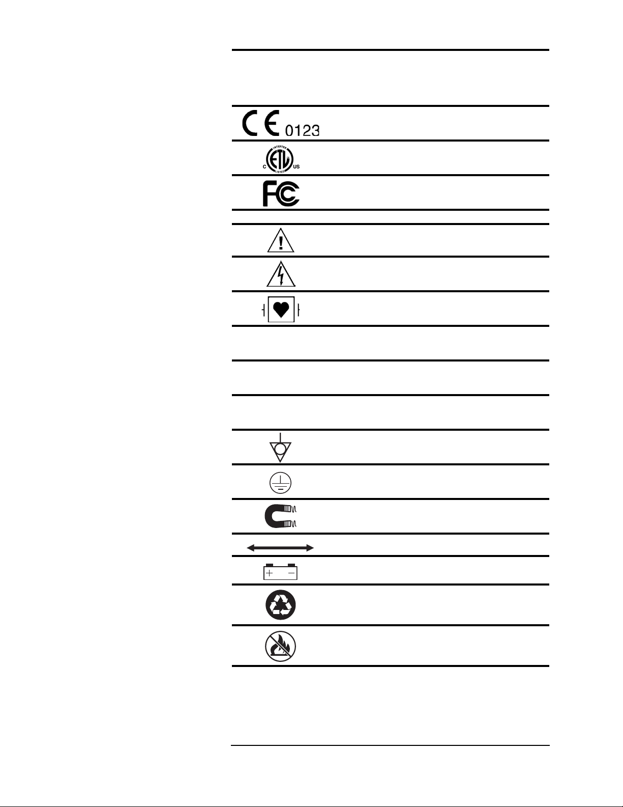
European Community Mark
ETL Mark
FCC (US Federal Commu nicat io ns Commi ssi on)
Mark
ATTENTI ON ! Re fer to O p erati on Manu al for
Information
Shock Hazard
Type CF Equipment, defib proof
Indicates no pr o te ctio n ag ai ns t i ngres s of wate r
(remote display)
Identifies th e d egree of prot ec ti on agai nst fl uid a s
drip-pro of (main monitor)
Identifies th e d egree of prot ec ti on agai nst fl uid a s
drip-proof (power supply)
Equipotential Terminal
Protective Earth
Indicates the MR magnet and power
Indicates distance between MR magnet and monitor
Indicates the presence of a battery
Recycle batte r ies following ho spit al prot oc ols an d
local environme nt al re gu la tion s.
Do not incinera te! Keep away from fire or other
sources of extreme heat.
Page xiii
Page 14
MEDRAD
Symbol Definition
Veris
8600
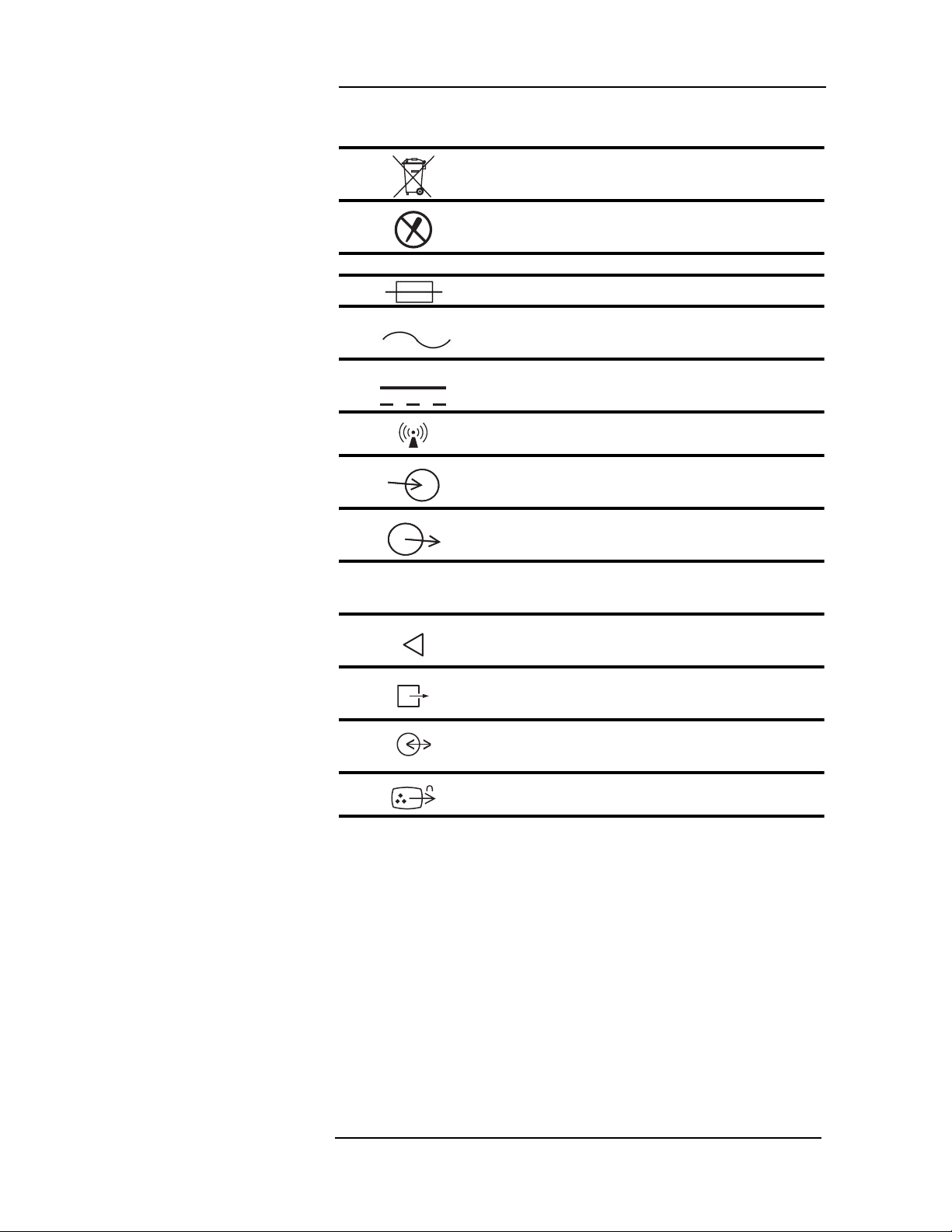
Dispose of batt er i es prop er l y in acc orda nc e wit h
hospital and local regulations.
Risk of electrical shock! Do not remove cover.
Refer servicing to qualified personnel.
System Symbols
Port Symbols
IOIOI
Fuse
Alternating Current (AC)
Direct Current (DC)
Wireless Device
Signal Inpu t
Signal Outpu t
Digital Output
Air Intake
Scavenging Port
Communication Port
Video Out
Page xiv
Page 15

Symbols
Miscellaneous Symbols
Symbol Definition
Technical Supp ort Phone Nu mbe r
Manufacturing Contac t
SN
REF
2
Serial Number
Part Reference Number
Place this side against the skin (Blood Pressure Cuff)
Placement of the cuff over the brachial artery.
Single use device o nly. Do not reuse.
Page xv
Page 16

Safety
Definitions
Warnings
Definitions for Warning, Caution, and Note symbols:
WARNING
!
CAUTION
!
NOTE: Indicates that important information follows, a tip that can help
you recover from an error, or point you to related details in the
manual.
• Read this manual entirely before using the monitor.
• Inspect For Damage! User should inspect th e sy ste m for signs
of damage. Do not use the system if failure is evident or
suspected.
• Possible burn hazard! Do not coil cables inside the MR scanner.
• Possible explosion hazard! Do not use the monitor in the
presence of flammable anesthetics. The equipment is not
suitable for use in the presence of a flammable anesthetic
mixture with air or with oxygen or Nitrous Ox ide.
!
!
Designates a p oss ible da nger ou s situ at i on.
Non-observance may lead to death or the most
severe injuries.
Designates a p oss ible da nger ou s situ at i on.
Non-obser vanc e may lead to min or in ju r ie s or
damage to the pr odu ct.
WARNING
!
!
• Possible ex plosion hazard! Do not use the monitor in the
presence of gas mixtures which m ay be flammable.
• Cables, tubing, and lead wires may present a risk of
entanglement or strangulation! Ve ri fy safe and proper
positioning of these items at all times.
• Unapproved modifications to the monitor may cause unexpected
results and present a hazard to the patien t.
• Risk of electrical shock! Do not remove cover . Ref er servicing to
qualified personnel.
• All cords must have hospital grade plugs and be plugged into
hospital grade outlets. (The electrical installation of the relevant
room must comply with NFPA 70: Nati onal Electric Code or
NFPA 99: Standard for Health Care Facilities. Outside the
United States, the relevant room must comply with all electrical
installation regulations mandated by the local and regional
bodies of government).
• Do not bring tools cont ainin g ferrous material in to the m agnet
room. Risk of serious inju ry and/or damage to equipment ca n
occur.
Page xvi
Page 17

Safety
WARNING
!
• Do not route gating cables near or within the s canning volume.
• Apply brakes to preven t movement.
• Do not re-use accessories labeled as single use. Risk of patient
contamination may occur.
• Improper disposal of batteries may result in explosion, leakage,
or personal injury. Do not open batteries. Do not dispose of
batteries in a fire. Follow all local regulations concerning the
disposal of spent Lead-acid and Lithium-Ion batteries or contact
MEDRAD for assistance.
• Connect only MEDRAD approved three-lead or five-lead ECG
cables from the patient to the ECG module. Do not connect any
other signal source to the ECG module.
• There is no defibrillator sync hronizati on ou tput on the Veris
monitor. Make no connections between the Veris and a
defibrillator.
• Leakage currents may increase if other equipment is
interconnected to the patient. The incr ease d lea kage cur rents
may present a hazard to the patient.
!
• PACEMAKER PATIENTS: This device does not inclu de
pacemaker spike rejection capability. Heart rate readouts
derived from the ECG patient connections ar e li kely to display
erroneous high or erratic rates when a pacemaker is in use.
Keep pacemaker patients under close surveillance. For
pacemaker patients it may be advisable to select the SpO
function as the primary heart rate sourc e.
• High Frequency (HF) surgical equipment may affect ECG
operation. The system is not designed to operate in the
presence of ESU interference. The patient may be burned.
Patient burns can also result from defective HF surgical
equipment neutral electrode connectio n.
• The heart rate calcul ated by the monitor may be affected by
cardiac arrhythmia.
• Do not take the remote display or the ECG module battery
charger into the MR scanner room. These contain ferromagnetic
material and can be strongly attracted to the magnet caus ing a
safety hazard.
• Do not use with an open MRI. Use of the moni tor in an open
MRI may result in erratic or unavailable monitoring.
• Do not stand or sit on monitor ac ces sor ie s tray. Possible injur y
can result from falling.
2
Page xvii
Page 18

MEDRAD
• Do not lift the monitoring system by the tray. Possible injury can
• U.S. Federal l aw restri cts this device to sal e by or on the or der
Veris
8600
WARNING
!
result from heavy weight.
of a physician.
!
Cautions
CAUTION
!
• Use only accessories des igna ted for use with this m onitor. Use
of accessories not designated for use with the Veris monitor can
cause inaccurate measurements and/or a sa fety hazard for the
patient.
• Equipment accuracy may be affected at extreme temperatures.
• Do not store equipment at extreme temperature. Temperatures
exceeding specified storage temperatures could damage the
system.
• Avoid routing the DC cable through the magnet room do or.
Possible damage can occur to the DC cable and/or the scanner
room door.
• Do not press on the keys with sharp or hard objects. This c ould
damage the keys. Use only your fingertips to press on the keys.
• Changes or modifications not expressly approved by MEDRAD,
Inc., may void the user's authority to operate the equipment and
may also void the warranty.
• Do not use the monitor in the path of a Li near Ac cel erator or
Positron Emission Tomography (PET) scanner beam. This could
result in inaccurate physiologic parameters or waveforms.
!
• Transporting the m onitor in a mob ile sc anner trailer can l ead to
damage from shock, vibration, or extreme temperatures.
• Do not allow the conductive parts of the pati ent el ectr odes to
contact other conductive parts, includin g ground (ea rth).
• Do not tip the monitor. Possible injury can res ult from falling.
• Do not stand on power supply enclosure. Injury fr om tr ipp ing o r
falling can occur.
• Do not stand on the base. Possible injury can result from falling.
• Do not pinch cables between the table and the bore. This can
damage the cables.
• Do not roll the monitor over or step on cables. This can damage
the cables.
Page xviii
Page 19
CAUTION
!
• Do not bend fiber optic cables too tightly. Follow cable
manufacturers specifications for bend allowance.
• If a probe falls on the floor or into liquid, clea n the probe
following proper cleaning methods. If the probe is not properly
cleaned, inaccurate physiologic parameters or waveforms may
result.
• Do not place more than 40 pounds (18 kg) on the tray.
!
Safety
Leakage Current
Voltage Fluctuations
Equipotential Ground
The monitor complies with leakage current limits required by medical
safety standards for patient-connected devices. The Veris monitor
conforms to EN 60601-1 standards. A haz ard c aused by the
summation of leakage currents is poss ible, when several pieces of
equipment are interconnected.
When operated in the line voltage range specified in this manual any
minor fluctuations will have a negligible effect. Very low line voltage
will cause the monitor to revert to battery power. Very high li ne
voltage may cause damage to the charger circuits. The monitor is
designed with circuitry that will turn the unit off before spurious
readings can be caused by a low batter y condition.
Health care providers and patients are subj ect to dange rous,
uncontrollable compensating currents for electrical equi pment.
These currents are due to the potential differences between
connected equipment and touchable conducting parts as found in
medical rooms.
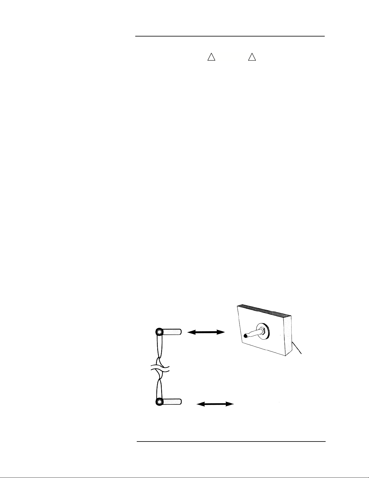
The safety solution to the problem is accomplished wi th c onsistent
equipotential bonding. Medical equi pment i s fitted with con necti ng
leads made up with angled sockets to the equipotential bondi ng
network in medical rooms.
Equipotential
Connection Lead
(Socket)
Terminal
Equipotential
Connector
Earth Ground
Page xix
Main
Body
Page 20

MEDRAD
Veris
8600
Software Error Related
Hazard Mediation
Potential Interference
MEDRAD, Inc., has quality control practices and procedures in place
to review potential hazards as they relate to software. The monitor
utilizes a four-digit year for all date, time, and leap year calculations.
This device has been tested to 60601-1-2 specifie d levels for
emissions of and immunity to electrical interference. External
disturbances which exceed these levels, such as motor driven tools,
may cause operational issues with this device. Other devices which
are sensitive to a lower level of emissions than those allowed by
IEC 60601-1-2 2nd Edition may experience operational issues when
used in proximity to this device.
MAGNETIC FIELDS
Always position the Veris Base, Base Plus, and Cardiac monitors at
or outside the 2000 Gauss line. Always position the Veris Anesthesia
monitor at or outside of the 500 Gauss lin e. This m onitor is designed
specifically for MR compatibility and is 1.5 and 3T c ompa tible. It will
not cause interference with MRI image quality, nor will its
performance be affected by the magnet field.
The "T" wave may become excessively large or inverted with the
patient in the magnetic field. T his effect is due to hem odyn amic flow
induced voltage and may interfere with QRS detection. Tr y other
leads and/or electrode placements for best results.
Use of Anesthetics
Biocompatibility
CONDUCTED TRANSIENTS
The monitor conforms with IEC 1000-4-4, and IEC 100 0-4-5 for
conducted transients, and will operate with negligible adverse effects.
X-RAY, CT, ULTRASOUND, AND/OR NUCLEAR MEDICINE
The monitor will operate with negligible adverse effects in these
environments. However, the monitor should not be placed directly in
the radiated beam, which could damage the internal electronics of the
monitor.
OTHER INTERFERENCE
There is a negligible adverse effect to the monitor from infrared
energy and defibrillation.
Do not use this device in conjunction with flammable anesthetics
such as cyclopropane and ether. The monitor can sample from pur e
oxygen environments, but the monitor itself should never be placed
inside an oxygen rich environment, such as a n oxygen tent or gas
containment apparatus. Proper anesthetic gas waste recovery should
be used.
All patient-contact or user-contact m ater ials in this moni tor and i t's
accessories have passed ISO 10993-5, -10, & -11 bioc ompati bil ity
tests or have been in use in clinical environments in l arge num bers
over an extended period of time predating these standards.
Page xx
Page 21

Safety
Probes Fall in Fluids
FCC and Industry Canada
Compliance
Audible Pulse Tone
Whenever probes fall and land in fluids, clean the probes according to
the cleaning instructions in “Cl eanin g and Disi nfecting” on page A-1.
This device complies with Part 15 of the F CC Rules.
Operation is subject to the following two conditions:
1. This device may not cause harmful interference, and
2. This device must accept any interference received, including
intereference that may cause undesired operation.
WARNING
!
• Changes or modifications no t expressly approved by the par ty
responsible for compliance could void the user’s authority to
operate the equipment.
The term “IC” before the certification/registration number only
signifies that the Industr y Canad a tec hnical s pec ific ations were m et.
IC: 5338A-CSI8600
The amplitude of the audible pulse tone remains constant regardless
of changes in patient parameter measureme nts.
!
Disposal Accessory Disposal
Latex Content
Discard disposable medical waste according to your instituti on's
policies and procedures to prevent biological contaminati on. Se e
“Disposal” on page A-7.
This MEDRAD product (patient monitor s and ap proved accessori es)
are free from latex in any location that may result in patient co ntact.
Page xxi
Page 22

Introduction
Description
Intended Use
The VerisTM 8600 patient monitor is design ed for use in the MRI
environment. It interprets and displays physiologic data as waveforms
and numeric information which, depending on the configuration of the
system, may include ECG, NIBP, SpO
temperature, O
and alerts may be set for each parameter. Monitored parameter data
is stored as tabular trend information and may be pri nted or
downloaded.
The system is intended to moni tor physiological paramete rs of
patients within any health care environment, sp ecifi cal ly in the MR
environment. The user, responsible to interpret the monitored data
made available, will be a professional health care provider.
Physiological data, gas monitoring, sy stem alarms, and patient
analysis will be available to the care provider from the monitor.
The monitor shall be MR compatible based on the FDA guidelines for
equipment to be used in MR.
There are two distinct needs for patient monitors in MR:
• Vital signs monitoring, to monitor medically unstable patients or
patients under conscious sed ation, as r equi red by the JCAHO.
• And, provide image gating, to gate image ac quis ition to a
physiological parameter, such as the cardiac cycle.
, anesthetic gases, and IBP. User defined alarm limits
2
, CO2, respiration,
2
There is the additional requirement for the accurate functi on of th e
equipment in the MR environment. The monitor us ed in the scan
room shall not be affected by the radio frequency pulse or gradient
fields and shall not produce any RF interference on the image.
The monitor (including accessories) shall be capable of monitor ing a
full range of patients from neonate to adul t.
Page xxii
Page 23

Introduction
Clinical Use
Before you Begin
This manual provides separate sections for measured parameters.
These sections provide instr ucti ons for patient connections and
monitoring. The caregiver is expected to be fully familiar with patient
monitoring techniques and with the functi ons of this mo nitor before
using it with a patient.
This system is designed to onl y m onitor one patien t at a time p er
monitoring system.
Protect yourself and your patient. Read the precautions for each
measured parameter that appears in each meas ure d parameter
section.
These instructions d esc r i be the use of the basi c sampl ing devices
and accessories that come with your monitor. An extended list of
approved accessories can be found in “Accessories” in Appendix D of
this manual.
The monitor should always be checked by the caregiver before use
for actual patient monitoring. Perform the following procedure before
using the monitor with each patient.
1. Make sure the monitor has been fully charged b efore use.
Check that the AC (Mains) power cord is plugged in for longterm monitoring situ ations.
2. Check the menus and default settings to confirm that the
monitor is setup correctly.
3. Examine the accessor ies for wear, damage or contamination.
Replace or disinfect the accessories as req uir ed.
4. Turn the de sired monitoring modules to ON in the PARAMS
softkey window.
5. Select the correct mode of operation (Adul t /Pediatric/Neonate)
by entering the patient size in the ADM/DIS softkey window.
CAUTION
!
• All accessories connected to the pa tient m onitor must compl y
with all applicable UL (Underwriters Laborator ie s) sta ndards
and IEC standards for such products.
• Substitution of recommended sensor and sampling accessories
may cause inaccurate measurements and degrade patient
safety, or may damage the monitor.
!
Page xxiii
Page 24

Page 25
1 — Panel Features
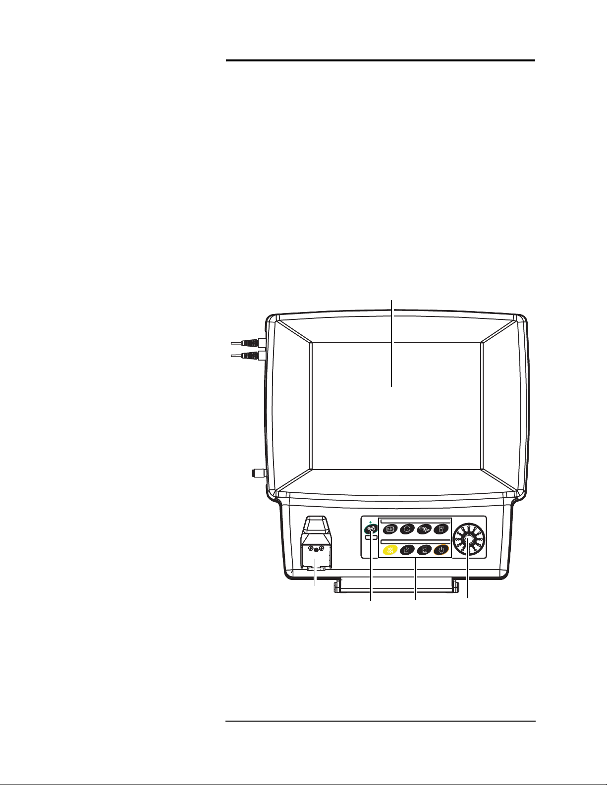
Front Panel
This section provides an overview of the
panels, switches, accessory connections, and communicati on
sockets.
The front panels of the monitor an d the o ptiona l r emote d isp lay
feature a color flat-screen display. Located bel ow the screen i s the
primary c ontrol pa nel equipped with the power button, eight
dedicated function keys and a menu knob. Menu selections are
displayed on the screen and can be selected via the menu knob. The
keypad is push-button style, composed of a touch-sensitive
membrane.
The water trap receptacle is also located on the front of the main
monitor (Anesthesia units only) .
Color Display
Veris
8600 monitor’s control
Water Trap
Receptacle
(Anesthesia
Monitors only)
Figure 1-1:
Power
Switch
Veris
8600 Front Controls
1 —1
Keypad
Menu
Knob
Page 26
MEDRAD
Veris
8600
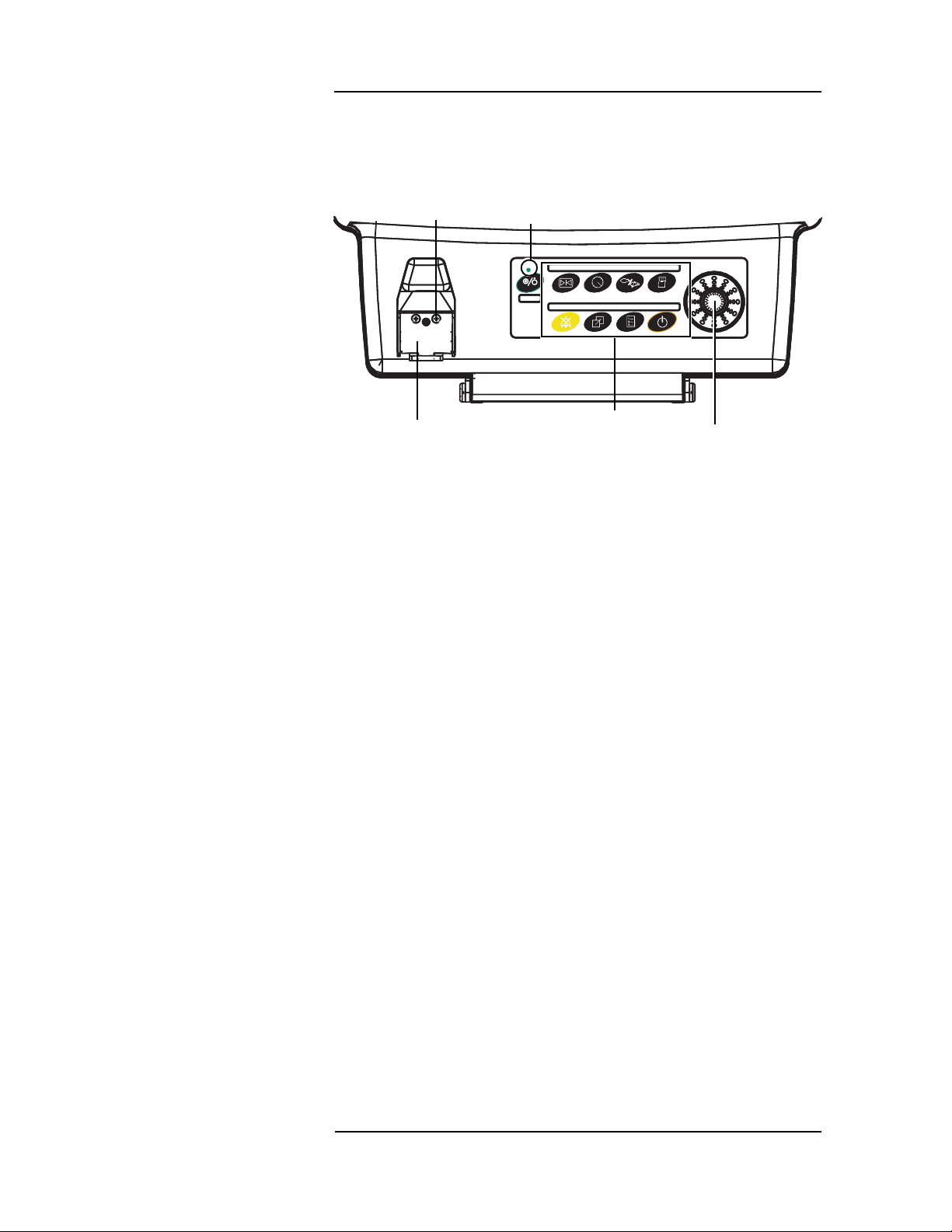
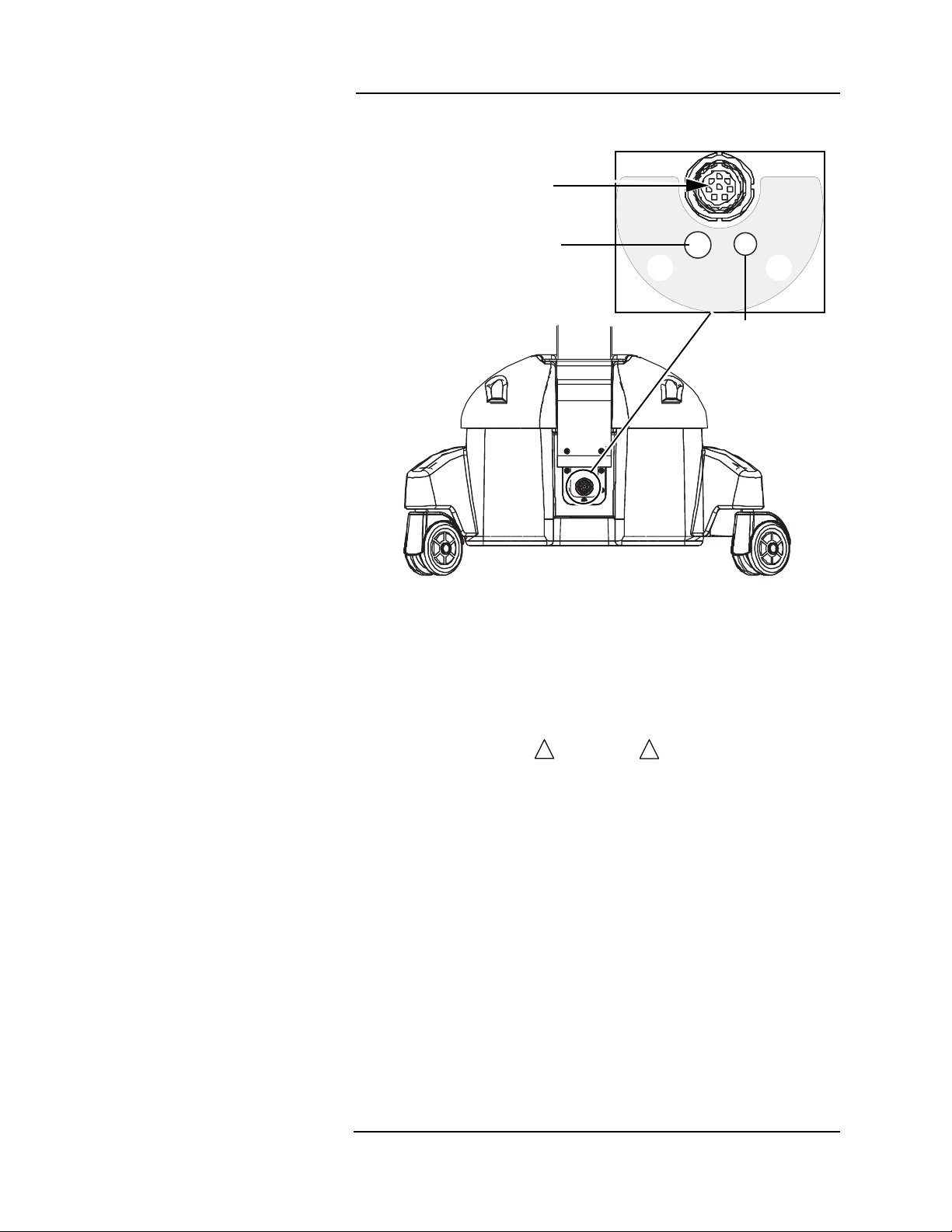
A green LED indicator is located above the power (ON/OFF) key. The
indicator is on if AC power is present.
Sampling
Line
Connection
AC Power
Indicator
Menu Knob
Color Display
Water Trap and
Gas Sampling Connec tion
Water Trap
Keys
Menu Knob
Figure 1-2: Detail of Lower Front Panel
The menu knob can be turned le ft or r ight to make selections from
any of the menus that appear on the front display. The selected menu
option can then be activated by pressing in on the menu knob.
The display provides real-time waveform and numerical data of the
measured parameters. Additional menus and menu options whic h
may be selected and activated by the menu knob are also displayed
on this and the optional remote dis play screen.
The water trap connection is a feature on Anesthesia and Anesthesia
Function
with Temperature models only. MEDRAD
analysis capability have a blank plate in this loc ation. The water trap
is easily accessed on the fron t of the monito r. The gas samp ling line
is connected to the water trap and it is used for CO
agent monitoring. The sample li ne fi tting is a stan dard female Luerlock connector when using the WaterChek
Veris
monitors without gas
, O2, N2O, and
2
™
2+ water trap accessory.
1 —2
Page 27
1 —Panel Features
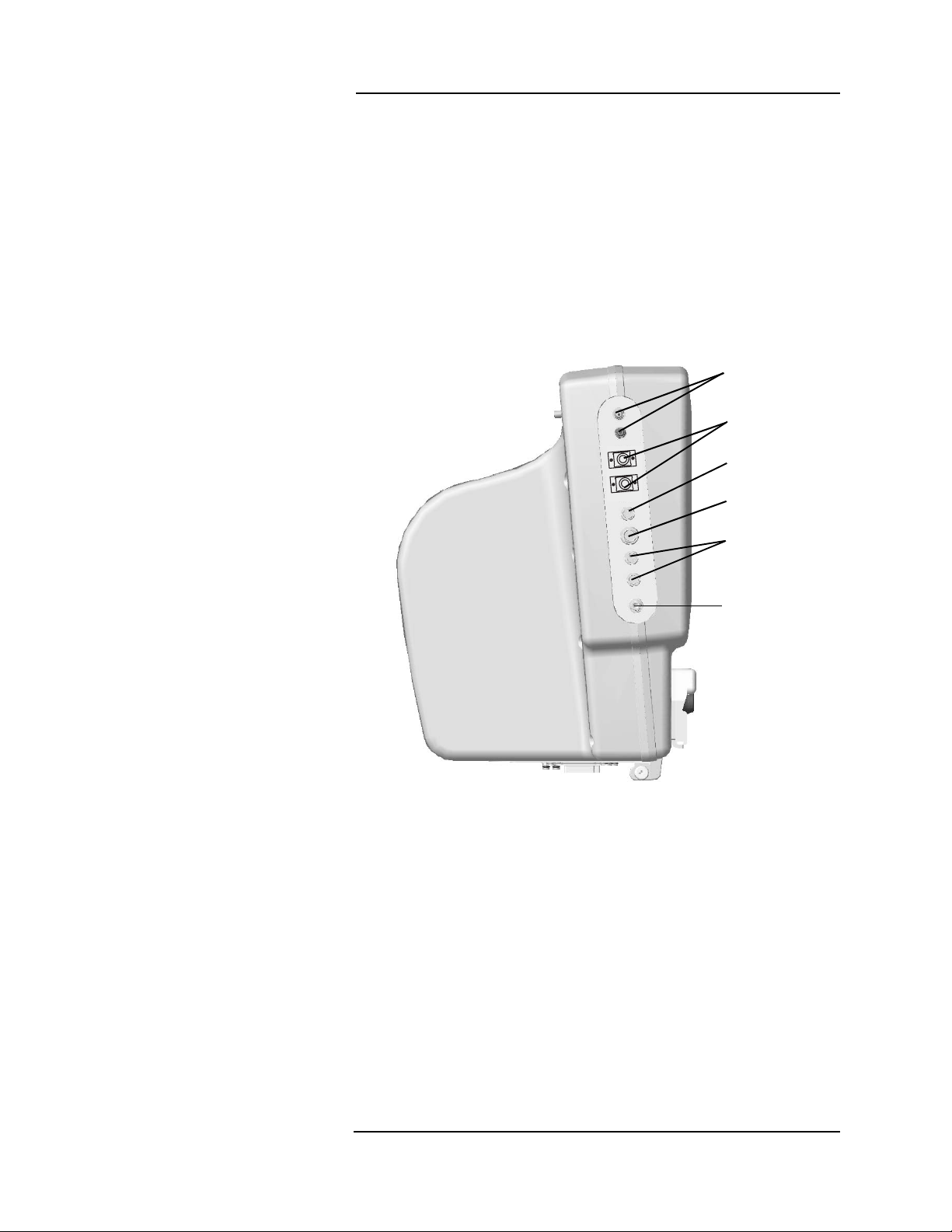
Left Side Panel (Mai n Monitor)
The left side of the main monitor has u p to ni ne c onnections for
patient monitoring. The electrocardiogram (ECG), pulse oximetry
(SpO
), and the non-invasive blood pressure (NIBP) connections are
2
standard on all
All potential
Veris
8600 models.
Veris
main monitor connections are desc ribed in the
picture below.
The optional remote display has no patient c onnections.
More information about accessory connections can be found in the
patient monitoring sections of this ma nual.
ECG Input/
Output
Temperature
Gating
Signal
SpO
2
IBP
Figure 1-3:
Veris
8600 Left Side
NIBP
1 —3
Page 28
MEDRAD
Veris
8600
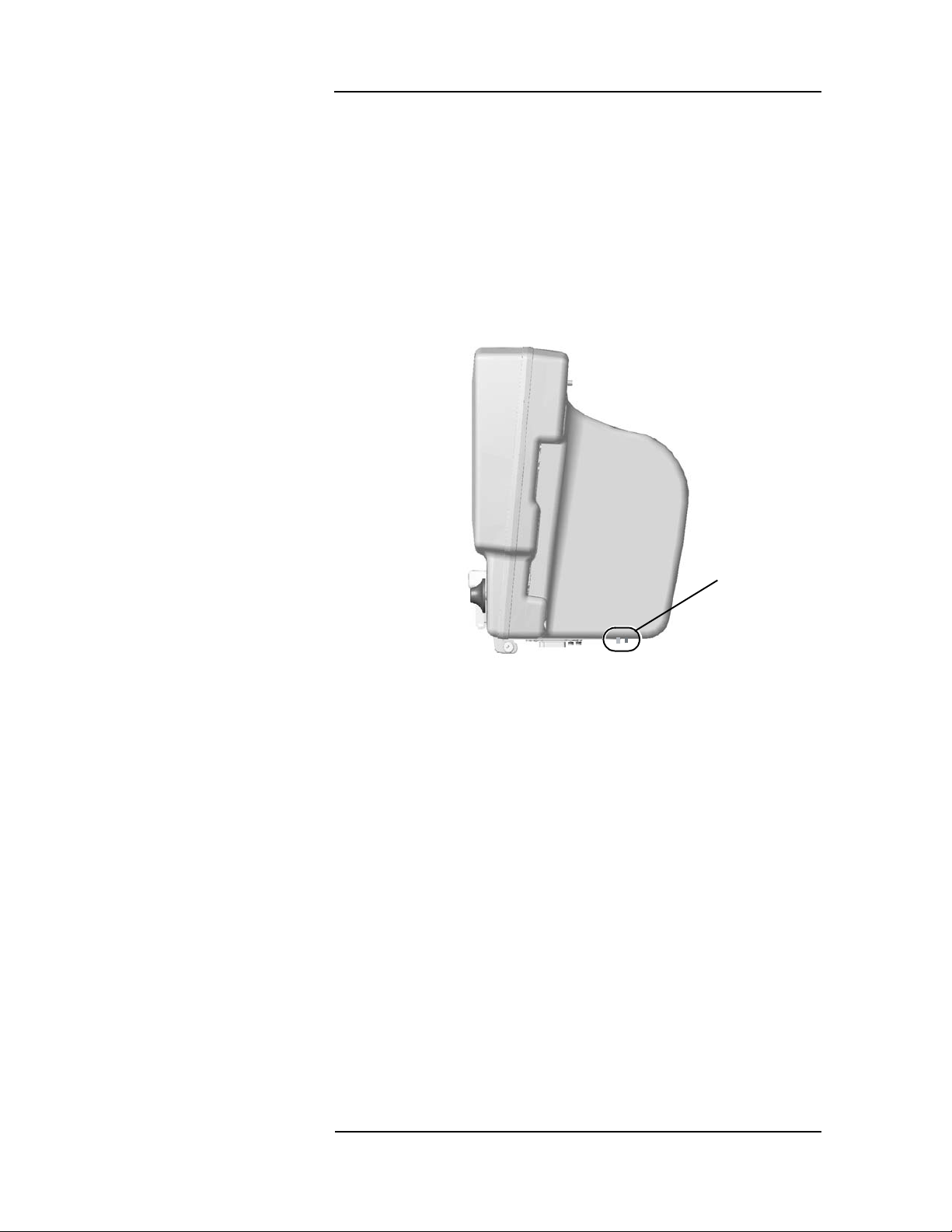
Communication Port
(Main Monitor)
There are two fiber optic ports at the bottom of the monitor. One is an
input port and the other an output port. These ports, on both the main
monitor and the remote display, are for fiber optic com munication
between the main monitor and the remote dis play. See the
Installation Instructions for installing the fibe r o ptic com municatio ns.
See “Figure 1-8:: Remote Display Fiber Optic Connection s” on
page 1-7 for the location of the fiber optic ports on the remote display.
NOTE: These connections have pro tec tive co ve rs that nee d to be
removed before use.
Fiber Opti c
Input and
Output
Connectors
Figure 1-4: Main Monitor Fiber Optic Connections
1 —4
Page 29
Main Monitor Base
Connections
1 —Panel Features
DC Connection
Exhaust Port
Air Intake
Port
Chassis Ground
DC Connection
Exhaust Port
Air Intake Port
DC Connection & Exhaust Port
Figure 1-5: Main Monitor Base Connections
The
Veris
monitor has an interna l c hassis ground.
A DC power cable connection is located at the center of the base of
the patient monitor. Attach the cable from the power supply in this
socket.
CAUTION
!
• Ensure that the cable from the power source to the monitor base
is placed in an area free from traffic to prevent tripping and/or
damage to the cable.
The exhaust port is located o n the base of the Anes thesi a mon itor
assembly by the DC connection. The scavenging kit fits this nozzle.
Use the scavenging kit and a waste gas recovery system when
anesthetic agents are present in gas sample s.
An ambient air intake port (located next to the exhaust port on the
base of the Anesthesia monito r asse mbly) is used for making zero
gas concentration calibrations. Do not block or attach anything to the
air intake port.
!
1 —5
Page 30
MEDRAD
r
e
Veris
8600
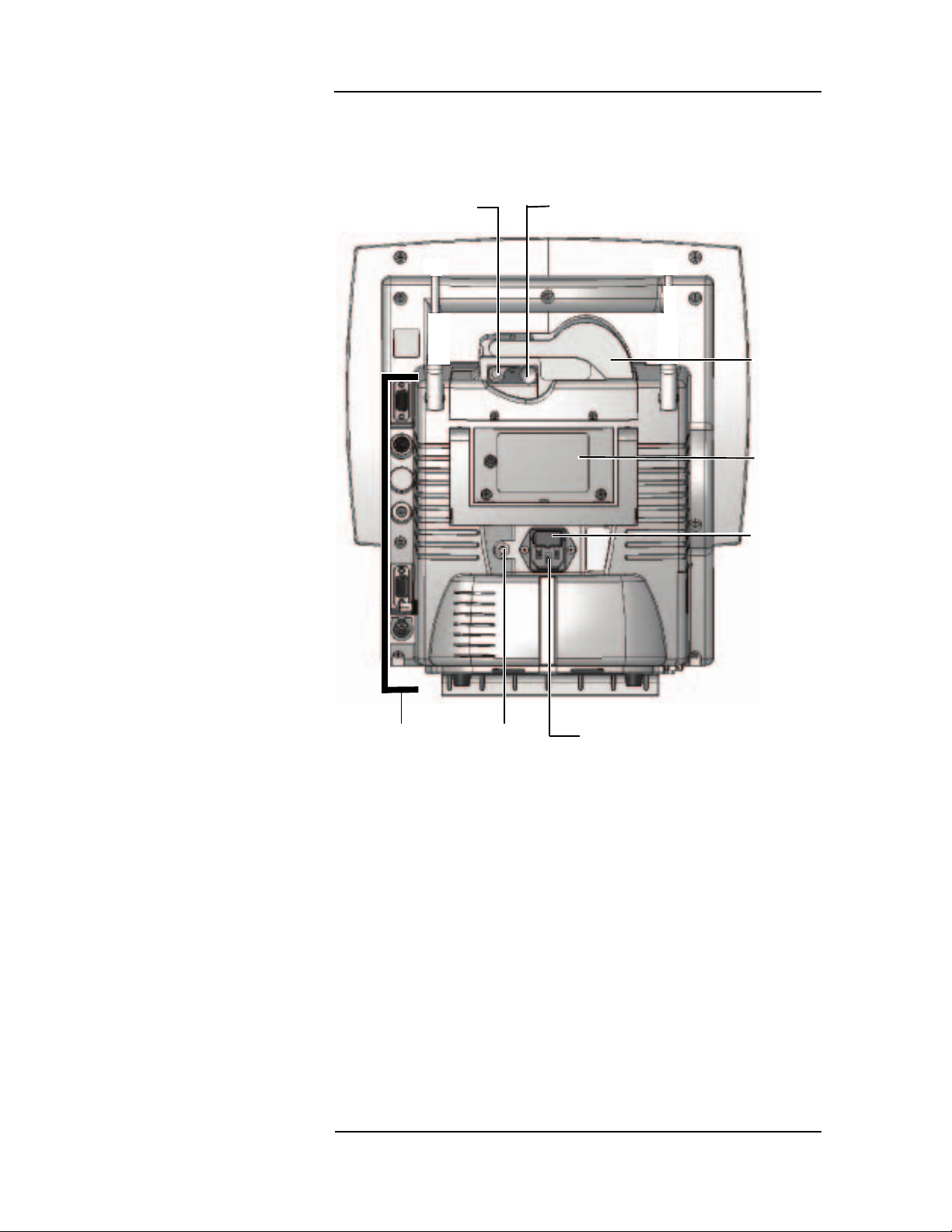
Remote Display
The remote display displays the patient data in another location .
Changes to the display can be made from the re mote displ ay and be
effected on the patient monitor.
Printer Release
Lever
Printer Feed
Advance
Printe
Door
Servic
Access
Panel
Fuse
Access
Panel
Communication
Connections
Figure 1-6: Remote Display Rear View
Chassis
Ground
AC Power
Connection
1 —6
Page 31

1 —Panel Features
COMMUNICATION PORTS (REMOTE DISPLAY)
There are three communications sockets available along the back
edge of the remote display. These connections provide links to
external printers, computers, and other medical d evices. See
“Printing and Data Ports” in Secti on 12 for more information about
serial printing and c ommunica tions
COM Port 1
Serial DB-9
COM Port 2
Mini DIN 8
Not Used
Video Port
Not Used
Figure 1-7: Communication Port s (Remote Display)
There are also two fiber optic ports on the right side o f the remote
display. These ports, on both the main monitor and the remote
display, are for fiber optic communicatio n between the m ain monitor
and the remote display. Se e the In stall ation Instructions for installing
the fiber optic communications.
NOTE: These connections have pr otecti ve cov ers that need to be
removed before use.
Fiber Optic
Input and
Output
Connectors
Figure 1-8: Remote Display Fiber Optic Connections
1 —7
Page 32

MEDRAD
Veris
8600
Printer
Accessory Tray
This printer door provides quick acces s to the in ternal printer paper
spool. The printer lever releases the printer rol lers for removing
jammed paper. The knob can be turned to feed paper. See “Printing
and Data Ports” in Section 12 for additional printer in formati on.
Printers are only available on
The monitor has an integral accessor ies tray where the user can
store and hang accessories.
• Do not stand or sit on monitor ac ces sor ie s tray. Possible injur y
can result from falling.
• Do not lift the monitoring system by the tray. Possible injury can
result from heavy weight.
• Do not place more than 40 pounds (18 k g) o n the tray.
Veris
8600 remote displays.
WARNING
!
CAUTION
!
!
!
Figure 1-9: Accessory Tray
1 —8
Page 33

Veris
8600 Configurations
1 —Panel Features
There are six factory-set confi gurations and one o ptional r emote
display available. See below fo r c onfig uration o ptions.
Number Description Features
3011991 Base MR Monitor Standard 3-lead ECG, SpO2, and NIBP
3011992 BasePlus MR Monitor Base plus Remote Display
3011993 Cardiology configuration Base plus 5-lead ECG, ECG Gating,
SpO
Gating, IBP.
2
The Remote Display is optional.
3011994 Cardiology with Temperature Cardiology plus Temperature.
The Remote Display is optional.
3011995 Anesthesia configur at ion Base plus 5-lead ECG, ECG Gating,
SpO2 Gating, IBP, O2, CO2, N2O,
agents.
The Remote Display is optional.
3011996 Anesthesia with Temperature Anesthesia plus Temperature.
The Remote Display is optional.
3010482 Remot e Display Remote display with printer and fiber
optic communications.
The instructions in this manual cover the operation of each of the
option packages listed above. For those models that do not include a
particular mo nitor ing modul e ( i.e. Agents), the system functions as if
that module is turned off.
1 —9
Page 34

Page 35

2 — Monitor Setup
This section provides an overview of the setup procedures for the
Veris
8600 monitor. Also see the appr opr ia te chapters on patient
parameter monitoring for parameter setup information.
The monitor should be set up by the health care provider before using
it on patients:
• Load paper (if remote display is present). See paper loa ding
instructions in “Changi ng Pr i nter Paper” on page 12-7.
• Charge all batteries (ECG module battery, main monitor
batteries.)
Preparations such as charging the batteries should be performed if
the monitor is new.
Battery Power
Charging the Battery
The monitor base contains two lead-acid gel batteries that when fully
charged provide a minimum of ten hours of operati onal use.
The
Veris
monitor is battery powered. The monitor inte rnally
recharges the battery when it is conn ected to the power supply. The
monitor can operate in continuous use for a minimum of 10 hou rs on
a fully charged battery. Charge the battery from the power supply
over night for approximately 12 hours.
WARNING
!
• If the electrical integrity of the earth ground is in doubt, the
power cord should be disconnected and the machine should be
operated from its internal elec tr ic al power source.
• Explosion hazard. Keep lighted cigarettes, spar ks, and fla mes
away from the battery.
• Avoid contact with battery acid! The batteries c ontai ns sulfu ri c
acid electrolyte which can cause severe burns and eye damage,
as well as illness from sulfur oxide fumes. Use necess ary
precautions when serv ici ng batte ri es.
• Do not short circu it the battery terminals. The resulting high current discharge can cau se bur ns.
!
• Do not operate the monitor with discharged or defective
batteries. Monitor failure could occur during AC power loss
which can compromise patient safety.
• Do not use the monitor if the batter i es ar e m issing .
2 —1
Page 36

MEDRAD
The
Veris
8600
Veris
monitor can function on AC or batter y power. MEDRAD
recommends that batteries be ful ly charged at all time s. If the
batteries are insufficiently cha rged, battery life is degraded and
shortened. If defective batteries are sus pected , con tact M EDRAD
Service or your local repres entative.
Battery Ind ic a tors
The battery icons are located on the lower portion of the main screen
as described in “Scre en Dis play and Interface” on page 2-5. The
battery icons change c olor to i ndicate the statu s of the batte r i es and
appear when using DC (batter y) or AC (Mains) power.
When AC is connected to the monitor (green light above ON/OFF ke y
is lit), the battery ic on color s are:
Amber: Batter y is char ging.
Green: Battery is fully charged .
When AC is not connected to the monitor (green light above ON/OFF
key is not lit), the battery icon colors are:
Green: Battery life is greater than 1 hour.
Yellow: Batte ry is weak. (less than 1 hour and more than 1 5
minutes of charge remains). A LOW BAT message
also appears.
Black: Batte ry is nearly drained. (less than 1 5 minutes of
charge remain). The LOW BAT message remains.
While using battery power there is a short delay between a change in
battery status and the updated dis play of the battery icons.
If the monitor is currently operating under AC power, the monitor may
take up to two minutes to display a change in battery s tatus.
The monitor also displays the battery s tatus for the E CG modul e in
the heart rate (HR) parameter box. The battery icon colors are:
Green: Battery life is greater than seven (7) hours.
Yellow: Batte ry life is less than seven (7) hours. Charge the
module battery soon
Black: This can indi cate the E CG m odule is not c onnected
to the monitor. Verify the module is connected to the
monitor.
If the module is connected to the monitor, the battery
is drained. ECG module will not operate. Charge the
module battery immediately.
2 —2
Page 37

2 —Monitor Setup
ALARMS PARAMS DISPLAY
Adult
V000 - NO ADMIT
SPO2: SENSOR
ZERO IP1
ZERO IP2
ADM/DIS CONFIG PRINT
14:12:59
SpO2
II
20
T1
T2
x1
x1
x2
aVR
CO2
CO2
EXP
INS
INS
INS
MAP
CYCLE OFF
200
1mV
ECG
SpO2
IBP1 ART
mmHg
mmHg
150 ml/min
IBP2 CVP
BPM
RESP Br/m
1mV
--
--
--
-
--.-
--.-
--
--
(---)
O2 HAL
GAS
ISO
17 0.4 1.1
21 2.3 3.8
---/---
+
ART1
CVP2
---/---
(---)
+
System Start and
Auto-calibration
To power up the main monitor, press the ON /OFF key located on the
front, left side of the control panel. If your system has a remote
display, power is applied via the s ame key on that component.
ON/OFF Key
Figure 2-1: ON/OFF Key
Immediately upon power up, the monitor displays the
screen. The software version appears on the scree n. For systems
with a remote display, a paper feed automatically activates.
• The informational message NO ADMIT is reser ved for future
use.
• Audible alarms are suspended for each parameter until the first
valid measurement has been taken for each parameter. Visual
alerts are always active.
Veris
splash
• If a patient had been previously admitted by the monitor, a
notice message RESUME MONITORING appears in a yellow
box. Press the knob to continue monitoring with th e cu rr ent
patient. Select NO to change the patient.
MAP
Adult
HRHRBPM
--
ECG
SpO2
RESP Br/m
%
--
CO2
EXP
INS
INS
INS
GAS
%
%
IBP1 ART
---/---
IBP2 CVP
150 ml/min
--
-
O2 HAL
17 0.4 1.1
21 2.3 3.8
--
14:12:59
--
ISO
mmHg
(---)
mmHg
1mV
II
x1
1mV
aVR
x2
SpO2
x1
CO2
200
ART1
0
20
CVP2
0
T1
--.-
T2
--.-
ALARMS PARAMS DISPLAY
ADM/DIS CONFIG PRINT
Same patient?
Resume Monitoring
YES
---/---
CYCLE OFF
ZERO IP1
ZERO IP2
(---)
SPO2: SENSOR
V000 - NO ADMIT
- +
- +
Figure 2-2: “Resume Monitoring” Dialogue Box
2 —3
Page 38

MEDRAD
Veris
8600
The monitor is comprise d of a number o f modul es which meas ur e
physiologic parameters. Some modules such as the oximeter are
ready for use within seconds of power up. Others such as the gas
bench take a few minutes to equilibrate.
Sensor and Probe Messages
Gas Calibration
Depending on the accessories attached to the monitor upon start up,
various messages concerni ng detached se nsor s an d prob es appe ar.
These are only visual alarms until valid measurements are taken by
the accessories, after which a low level alarm sounds when the
sensors and probes are disco nnec ted.
NOTE: LEADS OFF messages can be s et by the user to be Low,
Medium, or High level alarms.
If sensor and probe messages from unused m odule s be come a
distraction, these messages may be eliminated by turning the
respective module off. The OFF settings are located in the PARAMS
windows described in “PARAMS Softkey (Physiological Parameters)”
on page 2-21.
Units with invasive blood pressure capability indicate that either there
is no transducer attached (NO XDUCER) or that the transducer has
not been calibrated by the user (NOT ZEROED). In either case it is
not necessary to attach or zero the transducers in ord er to use the
other features of the monitor.
The agent gas detector may require a short warm up period and autocalibration sequence similar to an internal capnometer. The message
AGT:WARMING appears in the information message area. The
informational message AGT:MANUAL or AGT:AUTOMAT I C als o
appears indicating that the monitor is in either ma nual or automati c
primary agent identification mode. AG T: AUTO CAL indicates that the
agent calibration is in progress.
Respiration waveforms, capnogram, and numerical breath rate are
available in one minute from applying power to the monitor. The
monitor reaches full accuracy for agent concentrations in less than 20
minutes.
If the
Veris
system fails to auto-calibrate upon power up, the message
AGT:BAD CA L appears. If the syst em continues to fail autocalibration, contact MEDRAD Service or your local representative.
The oxygen monitoring module also requ ires au to-cali bration, wh ich
is performed at the same time as the agen t benc h calibrati on. If th e
O
module fails to calibrate, the message O2:SENSOR appear s.
2
Upon successfully completin g auto-cal ibratio n the m onitor di spl ays
values for monitored gases.
2 —4
Page 39

2 —Monitor Setup
Screen Display and Interface
The display is divided into dedicated areas for data and in terface
functions. The left side of the scre en is r eserved for wave form (up to
six) or graphic display. The uppermost waveform slot is factory set for
ECG. The remaining five waveform slots can be configured by the
user. The alarm silence icon (2 minutes or permanent) is shown in
the upper right cor ner of the first waveform.
The far right column is dedicated to reporting numerica l data, except
for NIBP and temperature which appear below the waveforms. The
color of each parameter is use r selec table. Therefore, any given
waveform and its corresponding numeric data appear in the same
color.
ECG Module
Battery
Gating
Remote
Communication
Status
Waveform Slot 1
Waveform Slot 2
Heart Rate
Numerical
Parameters
IBP Channel 1
Parameters
IBP Channel 2
Waveform Slot 3
Parameters
Waveform Slot 4
Waveform Slot 5
Waveform Slot 6
Temperature 1
Temperature 2
ALARMS
ADM/DIS
Patient Data Date Time
PA RA M S
CONFIG
DISPLAY
PRINT
NIBP Parameters
ZERO IP1
ZERO IP2
Priority Alarms
Info Messages
System Status
SpO2
CO
Gas Numerical
Respiration
2 Numerical
Parameters
Parameters
Figure 2-3: Screen Diagram
Main menu shown in grey above. The arrangement of the numerical
parameter boxes varies depending upon the waveforms selected to
be viewed and the waveform slot selected for the waveform. The
parameter box displays to the right of its corresponding waveform if
displayed in a wavefor m sl ot. T he s creen d isp lay is the sam e on th e
patient monitor and the remote display. Changes to the display can
be made at the patient monitor or at th e re mote displ ay.
The bottom porti on of th e dis play has spac e de dicated to the
following message types and functions.
• The main screen menu of selectable softkeys.
• Two message lines for alarms a nd al erts.
• A system status line for battery statu s an d patient s ize mode.
• The patient information bar, date stamp, and clock.
2 —5
Page 40

MEDRAD
ALARMS PARAMS DISPLAY
Adult
V000 - NO ADMIT
SPO2: SENSOR
ZERO IP1
ZERO IP2
ADM/DIS CONFIG PRINT
AUG-16-04 14:12:59
SpO2
II
20
T1
T2
x1
x1
x2
aVR
CO2
CO2
EXP
INS
INS
INS
MAP
CYCLE OFF
200
1mV
ECG
SpO2
IBP1 ART
mmHg
mmHg
200 ml/min
IBP2 CVP
HR
BPM
RESP Br/m
1mV
60
98
37
8
96.4
97.7
20
13
(125)
O2 HAL
GAS
N2O
17 0.4 39
21 2.3 64
145/105
ART1
CVP2
149/106
(127)
CO2
NIBP AGE 21:13 min
mmHg
Mixed ENF E 10.5 I 10.0
SpO2
II
20
x1
x1
x2
aVR
CO2
200
1mV
1mV
ART1
CVP2
Veris
8600
1mV
II
x1
1mV
aVR
x2
SpO2
x1
CO2
200
ART1
0
20
CVP2
0
T1
NIBP AGE 21:13 min
96.4
T2
97.7
ALARMS PARAMS DISPLAY
ADM/DIS CONFIG PRINT
149/106
CYCLE OFF
ZERO IP1
ZERO IP2
mmHg
(127)
MAP
SPO2: SENSOR
V000 - NO ADMIT
- +
- +
Adult
HR
BPM
- +
60
ECG
O2 HAL
GAS
%
17 0.4 39
E
21 2.3 64
I
Mixed ENF E 10.5 I 10.0
SpO2
%
98
CO2
EXP
INS
INS
INS
IBP1 ART
145/105
IBP2 CVP
37
8
13
AUG-16-04 14:12:59
N2O
RESP Br/m
20
CO2
200 ml/min
mmHg
(125)
mmHg
1mV
II
x1
1mV
aVR
x2
SpO2
x1
CO2
200
ART1
0
20
CVP2
0
Waveform Slots
Figure 2-4: Sample Interface Screen
The monitor has the capability to d isplay up to six waveforms
simultaneously.
The first trace is factory set to only disp lay an ECG waveform. The
user may select the lead type for this trace. All other displayed
waveforms are user selectable.
Each waveform slot disp lays the parameter or so urce al ong the left
edge of the screen. Amplitude bar and range ar e s hown at the
beginning of the slot if applicable to that typ e of waveform. The color
of each waveform may be selected by the user. The waveform slo ts
can be combined to form double high waveforms and waveforms can
be cascaded to fill multiple slots. See “Double Height S lots ” on
page 2-28 and “Cascaded Slots” on pa ge 2- 29 for details.
NOTE: The SpO
proportional to puls e volume. The SpO
automatically gain adjusted.
waveform display is not necessarily directly
2
waveform display is not
2
2 —6
Page 41

2 —Monitor Setup
VISUAL ALARMS WITH WAVEFORMS
The waveform slots are also used to display physiological alarms that
will appear at the top center of each slot. For a high priority alarm the
color of the message is red. For a medium priority alarm, the color of
the message is yellow.
The bottom five slots may be covered by menus and messages.
Since the top waveform slot is dedicated to ECG, the ECG waveform
and the ECG high and medium priority messages are always visible if
ECG is currently being monitored and the top s lot i s active.
See “Visible Alarms” on page 3-2 for a complete description of visual
alarms.
SILENCE ALERT STATUS
The silence alert visual icon appears in the upper right area of the top
waveform.
• The silence icon shows a bell with an "X" and an infinity symbol
when the SILENCE hard key has been pressed and held for
more than two seconds.
• The Alarm Suspend icon shows a bell with an “X” and the words
2 Min when the SILENCE hard key has been momentarily
pressed.
ALARM INHIBIT
The alarm inhibit icon appears in the parameter boxes when one or
more of an individual parameter’s alarms are tur ned OFF.
ECG WAVEFORM
The lead number and scale setting are displayed in the top left corner
of each slot set for ECG waveforms. The amplitude bar, shown in
white, indicates the scale in millivolts (mV).
SPO2 WAVEFORM
The wavef orm is auto ranging where the monitor attempts to keep the
waveform centered in the slot at all times. No amplitude bar is shown.
CO2 WAVEF ORM
The CO2 waveform, capnogram, is always displayed in percent
regardless of the units selected for displaying the numerical data. The
maximum range of the capnometer waveform is 12.5%.
BREATH BY BREATH BAR GRAPH (B×B)
The breath by breath bar graph is a method of representing the
concentration of CO
at the end of each breath. The data is al ways
2
displayed in percent with a maximum range of 12.5%.
O2 WAVEFORM
The maximum range of the oxygen waveform is 100%. The units are
always in percent.
2 —7
Page 42

MEDRAD
PRIMARY AGENT WAVEFORM
Veris
8600
The primary agent wavef orm is displayed in percentage only as is the
display for primary agent numer ical data. The wavefo rm is autoranging within the slot. Secondar y agen ts are no t dis played as
waveforms.
NITROUS OXIDE (N2O)
The N2O waveform is derived from the agent detector o f the
Veris
monitor.
IBP WAVEFORMS
The labels identifying the sour ce of the IBP waveforms appear
between the upper and lower range values at the beginning of the
waveform.
The waveform has both manual and auto-ranging features. The
selected range appears at the left si de of the waveform. The scaling
for IBP slots are locked at x1 and cannot be changed. Use the range
settings to adjust the appearance of the waveform on the screen. See
“Alarms and M ess ages” in S ecti on 3 for details.
Selectable IBP sites are as follows:
• Arter ia l ( ART)
• Pulmonary Artery (PA )
• Central Ven ous (CVP)
• Right Atrial (RA)
• Left Atrial (LA)
• Intracranial (ICP)
• Left Ventricle (LV)
• Right Ven tri cle (RV)
There are two IBP channels. The color of each ch annel can be
selected independently.
If the amplitude of the waveform exceeds the selected range the
waveform is clipped. An informatio nal l evel alarm OFF SCALE
appears in the Info Messages Box of the main screen display.
2 —8
Page 43

2 —Monitor Setup
ECG
HR
BPM
60
%
SpO2
98
RESP Br/m
20
CO2
CO2 mmHg
EXP
INS
INS
INS
200 ml/min
37
Numerical Parameter Boxes
HR
BPM
60
ECG
- +
The numerical parameter box area is directly to the r ight of the
waveform area. The area is broken into seven numerical boxes.
There are three additional numerical boxes below the waveforms.
The numerical parameter boxes display the measured value of the
vital sign being monitored, the uni t of me asure, and parameterdependent information (such as the source for the heart rate or
inspired/expired values for gases).
If a module is turned off in the PARAMS menu, the numerical
parameters are replaced by the word OFF in each location. Smart
parameters such as heart rate switch to another available module if
possible. An alarm inhibit icon a ppears i n the upper r ight corner or
right center of a parameter box if an alar m l imit is set to OFF. The
alarm inhibit icon is r ed with a whi te “ X” indi cati ng tha t an al arm is
turned OFF.
ECG BOX
The top parameter box, in the upper right hand corner, is dedicated to
display the heart rate. The source of the heart rate (i.e. ECG, IBP,
SpO
, or NIBP) is shown in the lower left corner of this box. The color
2
of the numeric display for heart rate matches the color of the
waveform source data.
The right half of the ECG parameter box displays the gating output,
the ECG module battery statu s, and an icon i ndic ating that the
monitor and remote display are communicating. The col or of the
gating icon matches the color of the waveform and numerical data of
the source (i.e., ECG gating reflects the color of the E CG waveform
and numerics).
CO2 mmHg
EXP
INS
INS
INS
37
8
SpO2
98
RESP Br/m
20
CO2
200 ml/min
%
SPO2 BOX
The SpO2 box displays the oxygen saturation in percent.
RESPIRATION BOX
The Respiration box, to the right of the SpO2 box, displays the
respiration rate and respiration source (i.e. CO
CO2 BOX
This box displays numerical values for expired and inspired CO2. The
label EXP stands for expired (end-tidal) CO
inspired CO
corner.
. The current Flow Rate is dis played in the upper ri ght
2
).
2
and INS stands for
2
2 —9
Page 44

O2 HAL
O2 HAL
GAS
N2O
17 11.0 39
21 10.5 64
Mixed ENF E 10.5 I 10.0
IBP1 ART
mmHg
mmHg
IBP2 CVP
( 13)
(125)
145/105
GAS
%
17 11.0 39
E
21 10.5 64
I
Mixed ENF E 10.5 I 10.0
N2O
MEDRAD
GAS BOX
Numeric data for oxygen and agent gases appear in the same box.
The oxygen value is listed first followed by the primary halogenated
agent and nitrous oxide concentrations. The top line lists expired
values and the second line lists inspired values. Values are always
shown in percent. An alarm inhi bit i con displays to the r ight of each
header to indicate alar m l imits s et to OFF.
The label Mixed appears before secondary agent concentrations
listed at the bottom of the gas parameter b ox. This indicate s that
more than one agent is detected in the sy stem and m easu res the
secondary agent detec ted. The abbreviated name of the secondary
agent is located after the Mixed label.
The label Wrong appears before secondary agent concentrations
listed at the bottom of the gas parameter box. The system detects an
agent other than one set in the configu ration of the s ystem. If us ing
more than one agent, set the Agent to Monitor sel ecti on in the
PARAMS menu to Auto. The abbreviated name of the secondary
agent is located after the Wrong label.
Veris
8600
IBP1 ART
145/105
(125)
IBP2 CVP
( 13)
mmHg
mmHg
If the internal gas features are shut off i n the PARAMS menu, the
displayed values are replaced by the word OFF in each location.
IBP BOXES
The monitor displays the systolic, diastolic, and mean press ur e
pulsatile waveforms. The systolic and diastolic values are shown in
large text. The mean value (MAP) is displayed below the systolic and
diastolic values in smaller characters. All MAP values ar e sh own in
parenthesis.
Non-pulsatile waveforms have only a mean value. Non-pulsatile
waveforms mean values are shown in large text and are centered in
the box.
2 —10
Page 45

MAP
CYCLE OFF
149/106
(127)
NIBP AGE
NIBP AGE
21:13
min
mmHg
MAP
CYCLE 4:00:00 ET 3:45:37
149/106
(127)
NIBP AGE
21:13
min
mmHg
T1
T2
96.4
97.7
149/106
CYCLE OFF
21:13
min
(127)
2 —Monitor Setup
NIBP BOX
The NIBP numerical box is located ne ar th e ce nter of the screen
mmHg
below the waveforms. It displays the systolic, diastolic, and mean
MAP
pressure after a NIBP reading has completed. The systolic and
diastolic values are shown in large text. The mean value (MAP) is
displayed to the right of the systolic and diastol ic values in small er
characters. MAP values are shown in parenthesis.
When there is no valid reading, dashes are displayed. A valid reading
is dashed after 30 minutes. If a valid reading is displayed, the age of
the reading is displayed. After 30 minutes the age of the
measurement goes to dashes; if there i s n o valid reading, the age
also appears as dashes.
NIBP AGE
149/106
CYCLE 4:00:00 ET 3:45:37
T1
21:13
min
(127)
96.4
T2
97.7
Main Menu
If a cycle time is set, the interval is displayed. Otherwise the cycle
mmHg
time displays the word OFF in the NIBP box. If a cycle time is ac tive,
MAP
the amount of time remaining until the next NIBP reading is
scheduled is displayed at the bottom right of the box.
TEMPERATURE BOXES
F
The top temperature numerical box is dedicated to temperature
channel 1. The lower box is dedicated to channel 2. The units (°F or
F
°C) appear in the upper right corner of each box.
The main menu area is directly under the Temperature and NIBP
boxes on the left-hand side of the screen. There are up to eight
selectable soft keys located on the screen as shown below.
NOTE: The
Veris
8600 screen layout depends on the configuration of
the monitor.
ALARMS PARAMS DISPLAY ZERO IP1
ADM/DIS CONFIG PRINT ZERO IP2
Figure 2-5: Main Menu
One of the eight softkeys is always highlighted. If the user pushes the
menu knob the menu window associated with the highlighted softkey
is displayed and the menu knob control goes to that new window.
Different soft keys are selected by turning the menu knob clockwise
or counterclockwise until the desired key is highlighted .
ZERO IP1 and ZERO IP2 do not access s ettings windows. On units
without IBP the ZERO IP1 and ZERO IP2 boxes are blank.
More information about the soft keys and their function is explained in
“Softkey Functions (Main Menu)” on page 2-14.
2 —11
Page 46

MEDRAD
Veris
8600
Alarm and Message Areas
System Status Box
- +
The two alarm lines are loc ated under the NIB P numerical box. All
alarm and error messages for NIBP, respiration, and temperature are
displayed in this area. ECG, SpO
, CO2, O2, N2O, Agent, and IBP
2
high and medium alar ms ar e di splayed here if there is not an active
wavef orm associated with them. All low level messages are displayed
in the top alarm line. The bo ttom line i s for informational me ss ages
and advisory level alerts only.
The informational, low, and medium level alarm warnings are colored
yellow and the high alarm warning mes sage s are r ed. For more
information about alarms see “A larm Description” on page 3-1.
The system status box is located directly below the two lines reserved
for alarms and messages.
BATTERY WARNING ICONS
There is space reser ved for two battery ic ons. The battery icons
represent the state of the inter nal rechar geable batter ies. See
“Battery Indicator s” on page 2-2 and “ Cha rging the Battery” on
page 2-1 for a complete description of the icons and battery charging.
PATIENT SIZE MODE
The next item in the status line is the patient mode. This message lets
the user know what the patient size or mode the system is in: ADULT,
PEDIATRIC, or NEONATE. The default physiological alarm limits may
change depending on which mode is cur re ntly in u se.
Patient Information and Clock
A Patient Information Bar runs along the bottom of the disp lay. This
area displays the last name (12 characters), the first nam e (1 0
characters) and middle initial (one c haracter) of the patient, the
hospital identification number for the patient (16 characters), and the
patient’s room number (five characters).
A clock appears to the extreme right of the patient information. Th is
displays both current date and time.
2 —12
Page 47

2 —Monitor Setup
Keypad
There are nine keypad buttons, including the ON/OFF button and the
eight dedicated function keys. Some of the keys have two functions.
The primary function i s a ctivated with a momentary press of the key.
A secondary function, if present, is activated when the key is pressed
and held for two seconds.
Key
Function
On/Off Power button. Press to activate the patient monitor
and press and hold to tur n the m onitor off.
Freeze A single press of this key freezes all waveforms on
the screen. Numeric data continues to be updated for
monitored parameters.
A second press of this key resumes conti nuous
waveform displ ay.
N
IBP Cycle/Stat Press th e key momentar ily to d isp lay the NIBP cy cle
popup menu on the screen.
Press and hold this key to begin a Stat measurement.
NIBP NIBP measurement star t key.
Press the key again to cancel an NIBP measurement.
Print Press once to begin printing or for serial output.
Press a second time to stop pr inti ng.
Silence Press this key momentarily to begin a 2 minute alarm
silence.
Press and hold the key to permanently sil enc e the
alarms.
Press the key again, a second time, to resume
normal alar ms.
Default Press this key momentarily to access custom default
profiles.
Press and hold the key to alter custom default profiles
(password MEDRAD
required).
Trend Displays the trend table when pressed momentar il y.
Press the key to exit the trend window.
While the trend table displays, press and hold to
access the trend settings menu.
Stand By Press this key momentarily to enter s tandby mode.
Press the key again to exit the standby mode.
When any of the keys is pressed once, a single audible beep notifies
the user that a primary function has been activated. When a key is
pressed and held a double beep notifies the us er that a secondary
function is selected.
2 —13
Page 48

MEDRAD
Veris
8600
Softkey Functions
(Main Menu)
Softkeys are selected by turning the me nu knob clockwise or
counterclockwise until the desired softkey is highlighted. In the
sample below the ALARMS softkey is highlighted indic ating that the
alarm settings window displ ays if the menu knob is pressed.
ALARMS PARAMS DISPLAY ZERO IP1
ADM/DIS CONFIG PRINT ZERO IP2
Figure 2-6: Main Screen Menu
If the menu knob is rotated, any window associated with the
highlighted softkey is displayed when the menu knob is pressed. The
menu knob then controls scrolling through that new menu window.
NOTE: For monitors without invasive blood pressure the two softkeys
at the right end of the main menu are dis abled and blank. The
invasive bl ood pr essur e zero buttons do not activate windows.
The top item (EXIT) on each menu window automatical ly highlights
when the window is activated. The user may simply press the menu
knob a second time to exit each window without making changes.
At the bottom of the first window there may be selections all owing
access to subordinate windows. Some windows an d se ttings
discussed in this manual may not be present if the feature is not
installed in the monitor. If an alarm has been turned OFF in the
PARAMS window, settings in other windows, such as alar m li mits,
may be disabled.
Changing Settings
Turn the menu knob to highlight items on these menu windows. Press
the menu knob to select the ite m. A sin gle s hort beep is generated.
The key press beep is audible even when alarms are silenced.
Some of the settings require a letter or number to be entered. Rotate
the menu knob to select the desir ed c haracter. Press the menu knob
to select the character.
If an error is made while entering in the ADM/DIS screen, a left arrow
character can be selected in order to back over the existing text. The
down arrow character can be selected to jump to the next line.
The arrow characters are not available when entering passwords.
2 —14
Page 49

2 —Monitor Setup
Saved Setting Profiles
Alarms and parameter default settings may be independently
modified as part of a customized default profile. Setting changes
generally remain after the monitor is power cycled.
• Changes made to the settings remain in cur rent memory until a
patient is discharged or the monitor i s left with out power.
• If the monitor loses its current setting it returns to the last profile
selected from the memor y. If no profile has ever been selected,
the initial profile is CUSTOM DEFAULTS and begins with the
same settings as the Factory Default Settings listed in “ Factory
Defaults” on page 2-38.
• The permanent Factory Default profile can be ac ces sed and
restored in the CONFIG window.
• The user defined profiles can be acces sed and res tored by
pressing the DEFAULT key.
Making and saving settings profiles is des cribed later in this manual.
Also see “Unit and Configuration Defaults” in Appendix B for
instructions for loading CONFIGURATION defaults (Base System,
Cardiac System or An esthesia Sys tem, dependi ng upo n your unit’s
configuration).
2 —15
Page 50

ALARMS Softkey
MEDRAD
Veris
8600
ALARMS PARAMS DISPLAY ZERO IP1
ADM/DIS CONFIG PRINT ZERO IP2
Figure 2-7: ALARMS Softkey Selected
This softkey allows access to all the parameter alarm settings. When
the menu is activated by pressing the menu knob, an alarm limit
settings window appears. The alarm window appears as the Ad ult ,
Pediatric, or Neonate window as set in the third item Patient size.
EXIT
Alarm Volume 5
ECG Lead Fail MEDIUM
Patient size Adult
HIGH LOW
Heart Rate 150 40
SpO2 OFF 90
NIBP Systolic 200 50
NIBP Diastolic 100 30
NIBP Mean 150 50
Temperature 1 °F 100.0 93.0
Temperature 2 °F 100.0 93.0
Respiration 36 OFF
CO2 Ins mmHg 10 5
CO2 Exp mmHg 55 20
O2 Ins % 100 18
O2 Exp % 100 OFF
Apnea 20 seconds
Other Alarms No Action
Figure 2-8: Alarm Settings Window (Adult)
The pediatric and adult setting s i nitia lly ar e ide ntic al, as factory
defaults, but can be adjusted independently and saved as desired.
EXIT
Alarm Volume 5
ECG Lead Fail MEDIUM
Patient size Neonate
HIGH LOW
Heart Rate 180 90
SpO2 OFF 90
NIBP Systolic 140 35
NIBP Diastolic 80 30
NIBP Mean 100 35
Temperature 1 °F 100.0 93.0
Temperature 2 °F 100.0 93.0
Respiration 60 14
CO2 Ins mmHg 10 5
CO2 Exp mmHg 55 20
O2 Ins % 100 18
O2 Exp % 100 OFF
Apnea 20 seconds
Other Alarm Setups No Action
Figure 2-9: Alarm Settings Window (Neonate)
2 —16
Page 51

2 —Monitor Setup
Primary ALARMS Window
ALARM VOLUME
The alarm volume can be set from 1 to 10. If the volume is set to 1 it
returns as 2 if the monitor is power cycled. To turn off the alarms use
the SILENCE key. See “Alarms an d Mess ages ” in Secti on 3 for more
information about alarms.
ECG LEAD FAIL
This is an adjustable alar m l evel setting for a condition where the
monitor cannot detect connected ECG l eads. Set thi s acco rding to
the protocols of the facility or to the specific patient nee d.
ALARMS SETTINGS BY PATIENT SIZE
The monitor retains separate alarm settings for three different patient
sizes. When the patient size mode is changed to Adult, Pediatri c, or
Neonate, the monitor recalls alarm li mit settin gs s pecific to ea ch
patient size.
The extended alarm limit windows for the optional features also have
size specific versions. As in the main screen, the p ediatr ic al ar m
settings are the same as adult in the Factory Default profile.
To set all the alarm limits, adjust the settings as ne ces sary including
the extended windows that appear under Other Alarm Setups. Then
change to the next patient size and adjust the settings again including
the extended windows. Repeat setting changes as necessary for
each patient size.
ALARM LIMITS
Alarms activate when a high alarm limit is exceeded or the measured
value drops below a low alarm limit. High and Low limit values can be
set to the same values. In such a case the monitor al ar m s wh en any
value but the selected value is measured.
CAUTION
!
!
• Turning an alarm limit off disables both the audible and visual
portion of the alarm.
• Some alarms automatic ally rese t when the monitor is power
cycled. See “Alarms at S tart Up” on page 3-3 for details.
The low limit alarm can never be set higher than the high limit alarm.
The high limit adjustment is simi lar ly restricted. When adjusting limit
values some of the range may not be available because the monitor
does not display ranges beyond the point that the other limit is set.
Alarm limits cannot be changed for monitoring modules that are
turned off. If an alarm limi t ca nnot be sel ected , che ck the PARAMS
menu to confirm the module i s turned on.
2 —17
Page 52

MEDRAD
OTHER ALARM SETUPS
Veris
8600
Activation of the Other Alarm Setups option at the botto m of the first
alarms window may reveal additional alarms screens if other
parameter modules are detected when the sy stem is powered up.
Invasive Bloo d Pressure
Alarm Settings
This selection is not available in Base or BasePlus configurations.
Select Inv. BP Setup to view the window. Alarm limits can be set by
IBP channel or by IBP site location.
EXIT
Systolic Diastolic Mean
HIGH LOW HIGH LOW HIGH LOW
IBP 1 200 50 100 30 150 50
IBP 2 15 1
Default Alarm Limits by Site
Systolic Diastolic Mean
HIGH LOW HIGH LOW HIGH LOW
ART 200 50 100 30 150 50
PA 40 15 15 5 20 10
LV 200 60 40 0 120 60
RV 50 20 20 0 30 10
LA 15 1
RA 15 1
CVP 15 1
ICP 15 1
<<< BACK
Figure 2-10: IBP Alarm Settings Window
The alarm limits in effect (current) are the two IBP channels shown at
the top of the screen. These can be s et to p ulsa tile or non-puls atile
sites. The limits at the bottom of the screen ar e us ed if the IB P s ite
location is changed in the PARAMS window.
The site alarm limits are for defaults settings only. Invasive blood
pressure for LA, RA, CVP, and ICP are non-puls atile and do not
report values for systolic and diastoli c p ressur e.
2 —18
Page 53

2 —Monitor Setup
Agent Gas Alarms
EXIT
Inspired Expired
HIGH LOW HIGH LOW
Agent 2.3 OFF 1.5 OFF
N2O 75 OFF OFF OFF
Default Alarm Limits by Agent
Inspired Expired
HIGH LOW HIGH LOW
HAL 2.3 OFF 1.5 OFF
ENF 4.8 OFF 3.2 OFF
ISO 3.6 OFF 2.4 OFF
DES 18.0 OFF 12.0 OFF
SEV 5.1 OFF 3.4 OFF
<<< BACK
Figure 2-11: Agent Gas Alarm Setting W ind ow
This selection is only available in Anesthetic and A nesth etic with
Temperature configurations. Select Agent Setup from Ot her Al arm
Setups to view the window shown above.
The agent alarm window appears i nitial ly the same for adult,
pediatric, and neonate mode. Agent alar m l imits c an be set
independently and saved, or stored as defaults if desired.
Any changes made are saved immediately to current memory.
PRIMARY HALOGENATED AGENT ALARM LIMITS
The first setting of the agent alarm window is the primary
halogenated alarm limi ts. The primary agent is determined in the
PARAMS menu and i s disc uss ed l ater in th is section.
The settings for the current primary agent can be changed in the
PARAMS menu. If the primar y agent is changed, the correspond ing
limits for the new primary agent are appli ed from th e default alarm
limits listed for each specific gas. Each time the prim ary agent gas is
changed any previous changes made directly to the first s etting
“primary agent” ar e l ost.
NOTE: Parameter limit alarms for the remaining four monitored nonprimary agents are not active even though their numerical values may
appear on the main screen as a mixed (secondary) agent. Any
halogenated agent not designated or determined as the primary
agent (that exceeds its threshold limit) is treated as a component of a
mixed gas for alarm purposes.
2 —19
Page 54

MEDRAD
NITROUS OXIDE ALARM LIMITS
Veris
8600
The second setting is for the nitrous oxide (N2O) alarm limits.
MONITORED HALOGENATED AGENTS
The
Veris
8600 monitor provides alarm limit settings for halothane,
enflurane, isoflurane, desflurane and sevoflurane. Only one of these
five monitored gases has active alarm limits depending on which has
been designated or automatically determined as the primary agent
for monitoring.
The anesthetic agents go by other names, as shown in the table
below. It is the responsibili ty o f the physician to corr ectly r ec ognize
and administer anesthetic gases. Th e
Veris
8600 monitor uses
international standard abbreviations, also shown in the table below.
International
Standard
Generic Agent Name Alternate Agent Name
Abbreviation
Halothane Fluothane HA L
Enflurane Ethrane ENF
Isoflurane Forane ISO
Desflurane Suprane DES
Sevoflurane
SEV
2 —20
Page 55

PARAMS Softkey
(Physiological Parameters)
2 —Monitor Setup
ALARMS PARAMS DISPLAY ZERO IP1
ADM/DIS CONFIG PRINT ZERO IP2
Figure 2-12: P ARAMS So f tkey Selected
When this softkey is activated a parameter settings window appears.
This softkey allows access to the physiological parameter settings.
Each of the sampling modules is listed her e and can be turned on
and off. Gaps may appear in the menu if features are not installed.
EXIT
HR Source Smart
Gating OFF
ECG ON
Cable 5 lead
Filter Monitor
Display Range MEDIUM
Auto lead switching YES
Color ¤
IBP 1 SITE ART RANGE 0 TO 200 ZERO None Color ¤
IBP 2 SITE CVP RANGE 0 TO 20 ZERO None Color ¤
Primary PARAMS Window
NIBP ON GASES ON
NIBP tone NONE
Color ¤
ECG/IBP/SPO2 Tone Vol 5
Other Params Menus No Action
Figure 2-13: Parameter Window
Selecting Other Params Menus activates additional windows:
•SPO
• Gas Menu
MONITORING MODULE ON/OFF SELECTION
Each monitoring module (
and Respiration) can be turned OFF or ON in the PARAMS softkey
window. The waveforms, numerical parameters, and messages for
that module do not display. T he au dible alarms associated with that
module are also disabled. The ON/OFF setting or absence of a
monitoring module can als o affect the Smart Heart Rate functi on.
COLOR SETTINGS
At the end of some monitoring mo dule s ettin gs, Color appears to the
right with color samples. The color sample indicates the current color
selected for the display of the numerical values and waveforms for the
monitoring module. The numerical values and th e waveforms always
have matching colors with the exception of the breath by breath
display, which is always in white.
, RESP, TEMP Menu
2
SpO2, ECG, NIBP, IBP, Temperature, Gas,
2 —21
Page 56

MEDRAD
Veris
8600
The colors can be changed as de sir ed. S elect the color settin g to
access the color sample box. Tu r n the k nob to sc roll through the
possible colors and press the knob to enter the selection. Colors red,
yellow, blue, green, orange, violet, light gold, and white may be
selected.
SMART HEART RATE
When Smart is selected for HR Source, the monitor generates a
numerical heart rate value from the remaining operating modules if a
higher lever module is turned off or lost. If the ECG signal is los t or
turned off, the monitor automatically switches to another available
source. The order is:
•ECG
•IBP
•SpO
2
•NIBP
The monitor generates a hear t rate from th e ECG mod ule, the IBP
module, the SpO
module, or from the NIBP (in that order of
2
preference). The NIBP heart rate is updated with each NIBP
measurement rather than being continuously updated with the ECG ,
IBP, or SpO
waveform data. When the heart rate is based on NIBP
2
data the numerical heart rate value is removed 2 minutes after the
last NIBP measurement was completed.
If a specific parameter is selected for HR Source, and that parameter
is lost, the monitor does not switch to another parameter for the heart
rate.
GATING
The gating function can be set to OFF, ECG Wave, SpO2 Wave, ECG
Pulse, or SpO
ECG CABLE
Pulse.
2
The monitor can be set to 3 lead or 5 le ad E CG.
NOTE: Base and BasePlus models only have 3 lead cap abili ties.
ECG FILTER
The ECG is set to Monitor mode for optimal filtering and cannot be
changed by the user.
DISPLAY RANGE
This setting controls the ECG signal gain. If it is set too high, the signal
may exceed the valid range for monitoring. The high level alarm
message ECG: SENS TOO HIGH displays. If this occurs, lower the
sensitivity setting. For general monitoring use the medium setting.
2 —22
Page 57

2 —Monitor Setup
ECG AUTO LEAD SWITCH
The PARAMS window settings for Auto Lead Switching are described
in “ECG Auto Lead Switching” on page 5-16. For general use, these
can both be set to the On posi tion.
IBP SETTIN GS
The two IBP channels can be configured separately. The choices are:
• Arter ia l ( ART),
• Pulmonary Artery (PA),
• Left Atrial (LA),
• Right Atrial (RA),
• Central Ven ous (CVP),
• Right Ven tri cle (RV),
• Left Ventricle (LV),
• Intracranial (ICP), or
•Off.
The ranges for IBP waveform display are also independe ntly
selectable.
The IBP channels can be zeroed using the setting from the PARAMS
window or from the main menu softkey, whichever is more
convenient.
IBP AUTO-RANGING
The monitor provides auto-ranging for each IBP channel indiv idu ally.
When auto-ranging is selected for a channel in the PARAMS window,
the monitor determines the bes t displ ay range based on previous
extremes of the waveform.
The scale changes to exceed the waveform maximums by at least 5
mmHg. The auto-ranging occurs when the PARAMS window is
exited. If the past extremes of the waveforms are exceeded, clipping
occurs. The new range remains until auto ranging is selected again or
specific range values are set in the PARAMS window.
NIBP SETTINGS
The NIBP can be set to generate a tone upon c ompl etion of eac h
measurement.
NOTE: Press the NIBP CYCLE/STAT key to access the cycle
settings.
HEART RATE TONE VOLUME
This feature can be set at the bottom of the first PARAMS window.
The tone can be set to volumes 1 through 10 or OFF. This setting only
controls the tone volume associated with the heart rate rhythm. It is
not affected by adjustments to Alarm Volume or the SILENCE feature.
2 —23
Page 58

SpO2, Respiration,
Temperature Menu
MEDRAD
<<<Exit
SpO2 ON
Average 12 seconds
Search time 20 seconds
Low limit alarm HIGH
Color ¤
Respiration ON
Temperature 1 ON
Temperature 2 ON
Unit of measure °F
Color ¤
<<<Back
Veris
8600
Figure 2-14: SpO2, Respiration, T emperature Parameter
Window
SPO2 SETTINGS
There are three settings specif ic to the S pO2 module; Average,
Search Time, and Low Limit Alarm.
SpO2 Average sets the duration of the inter val over which the SpO2
value is averaged. The settings for each are listed in seconds.
SpO2 Search Time sets the time interval from the time the pulse signal
is lost until the
The
SpO2 Low Limit Alarm can be set to either high or medium priority
SpO2 SEARCH message appears.
as desired. The monitor generates an alarm of that level when the low
limit threshold is passed.
RESPIRATION
Respiration is only available if the
Veris
monitor has CO2 (Anesthetic
and Anesthetic with Temperature models only). The source is always
CO
.
2
TEMPERATURE SETTINGS
The temperature channels can be turned ON or OFF and can be set
to read in either Celsius (C) or Fahrenheit (F).
2 —24
Page 59

2 —Monitor Setup
Gas Settings
EXIT
CO2 ON
Unit of measure mmHg
Color ¤
O2 ON
Color ¤
Agent
Agent to Monitor Auto
Flow Rate 200 ml/min
Flow Mode Exhaust
Agent Color ¤
N2O Color ¤
<<< BACK
Figure 2-15: Gas Settings
CO2 UNIT OF MEASURE
The CO2 numerical data can be dis played as mm/hg, Torr, kPa , or
volume percent.
AGEN T TO MONITOR
The primar y a gent for monitori ng must be corr ectly entered
depending on the monitoring alarm characteristic desired by the user.
The monitor has two modes of agent gas moni tor ing. T he user may
select a specific haloge nated a gent to be des igna ted as the primary
agent. The user may otherwise set the monitor to automati cally
detect and identify the current pr im ary gas of a mixture.
NOTE: If the user manually selects the primary agent for monitoring it
must be correctly entered.
WARNING
!
!
• Always confirm the primar y agent selection before use.
Incorrect primar y agen t setti ng may result in er roneous li mit
alarms. Alarm charac ter is tics of the moni tor are altered when
automatic primary agent detection is activated.
• Never substitute a primary agent setting for a different
halogenated agent, or any agent not listed! The agent detection
is specific to the listed gases only.
• The alarm WRONG AG ENT appears when the primar y agent
(that is manually selected by the physician) does not match the
primary ag ent detec ted. The WR ONG AG ENT alarm is
deactivated when automatic primary agent detection is
selected.
2 —25
Page 60

MEDRAD
Veris
8600
WARNING
!
!
• The halogenated agent waveform and waveform label may
automatically change to a di fferent halogenated agent when
automatic primar y agen t detec tion is used. If no p r im ary agent
is detected, dashes appear in the waveform label when
automatic primary agent detection is used.
The primar y a gent i s the halo genated agent having the highest
concentration during mixed gas conditions. Where only one
halogenated agent is to be used, the si ngle agent shoul d al ways be
the primary agent. The primary agent can be set to haloth ane,
isoflurane, enflurane, desflurane, sevoflurane, or automatic.
The selected primary halogenated agent has its own set of alarm
limits as described earlier in this section. This is for use when the
primary ag ent is s elec ted manually. When automatic primary a gent
detection is used, the agent alarm limits are updated at the time of
identification from the Default Alarm Limits by Agent settings. If the
primary ag ent is redefined automatically, the alarm limits are agai n
updated from the agent specific limits defin ed in the me nu.
FLOW RATE
The Flow Rate setting adjusts the amount of air that is drawn in by the
gas monitoring system. The monito r p rovides accurate values in
either 100, 150, or 200 ml/min settings. It is recommen ded tha t the
200 ml/min setting be used for better response tim e.
FLOW MODE
The flow mode of the
Veris
monitor is permanently set to exhaust and
cannot be changed.
2 —26
Page 61

DISPLAY Softkey
2 —Monitor Setup
ALARMS PARAMS DISPLAY ZERO IP1
ADM/DIS CONFIG PRINT ZERO IP2
Figure 2-16: DISPLA Y Softkey Selected
This softkey allows access to the display settings. When activated,
the display settings window appears. The monitor can display up to
six waveforms and has user selectable waveform slot configurations.
See “Waveform Slots” on page 2-6 for a list of displayed waveforms.
EXIT TYPE GAIN SWEEP SIZE
MM/S
Waveform 1 ECG II x1.0 25.0 50mm
Waveform 2 OFF x1.0 25.0 25mm
Waveform 3 ECG I x1.0 25.0 25mm
Waveform 4 PLETH x1.0 25.0 12mm
Waveform 5 aVL x1.0 25.0 12mm
Waveform 6 aVR x1.0 25.0 12mm
External Display OFF
Wa veform Description
Figure 2-17: Display Settings Window
The waveform area is located in the upper left-hand portion of the
display. The monitor ha s the capa bili ty to dis play six waveforms
simultaneously. The top waveform slots 1, 2, and 3 are 25 mm in
height. Wavefor m sl ots 4 , 5, and 6 ar e 12 .5 mm i n hei ght. Sl ots can
be configured in a variety of ways as described in the following text.
The wavefo rms may be adjusted in size and dimension by using the
settings provided. The gain listed on the D ISPLAY wi ndow settings
increases the display size of the waveforms. It does not control the
amplification gain of the source si gnal or th e height of the slot where
the waveform appears.
The parameters for the waveforms displayed are user selectable with
the exception of the first slot, which is always an ECG waveform. The
user can select which lead to dis play for the ECG waveform in the
first slot.
2 —27
Page 62

MEDRAD
ALARMS PARAMS DISPLAY
Adult
V000 - NO ADMIT
SPO2: SENSOR
ZERO IP1
ZERO IP2
ADM/DIS CONFIG PRINT
SpO2
II
T1
T2
x1
x1
x2
aVR
CO2
CO2
EXP
INS
INS
INS
1mV
ECG
SpO2
IBP1 ART
mmHg
mmHg
150 ml/min
IBP2 CVP
HR
BPM
RESP Br/m
1mV
60
98
37
8
96.4
97.7
20
13
(125)
145/105
+
+
CO2
O2 HAL
GAS
N2O
17 0.4 39
21 2.3 64
Mixed ENF E 10.5 I 10.0
MAP
CYCLE OFF
149/106
(127)
NIBP AGE 21:13 min
mmHg
AUG-16-04 14:12:59
Veris
8600
Double Height Slots
The monitor can display waveforms in three 25mm slots and three
smaller 12.5mm slots.
• Two 25mm slots can be c ombin ed to for m one 50mm slot.
• Two 12.5mm slots in the, bottom group, can be combined
together to form one 25mm slot.
• No more than two slots can be com bined to form a la rger
waveform display area
NOTE: Slots 3 and 4 cannot be combined.
Figure 2-18: Display Settings Window with Combined
1mV
II
x1
1mV
aVR
x2
SpO2
x1
CO2
T1
T2
ALARMS PARAMS DISPLAY
ADM/DIS CONFIG PRINT
To combine slots to form larger areas to display waveforms set the
lower slot TYPE to OFF. The slot above automatically increases in
size to fill the space.
EXIT TYPE GAIN SWEEP SIZE
MM/S
Waveform 1 ECG II x1.0 25.0 50mm
Waveform 2 OFF x1.0 25.0 25mm
Waveform 3 ECG aVR x1.0 25.0 25mm
Waveform 4 PLETH x1.0 25.0 25mm
Waveform 5 OFF x1.0 25.0 12mm
Waveform 6 ET CO2 x1.0 25.0 12mm
External Display OFF
Slots
HR
145/105
GAS
96.4
97.7
NIBP AGE 21:13 min
149/106
CYCLE OFF
ZERO IP1
ZERO IP2
SPO2: SENSOR
V000 - NO ADMIT
- +
- +
Figure 2-19: Double Height Slots
2 —28
(127)
Adult
mmHg
MAP
60
ECG
IBP1 ART
BPM
- +
mmHg
(125)
IBP2 CVP
mmHg
13
37
8
RESP Br/m
%
CO2
150 ml/min
20
N2O
SpO2
98
O2 HAL
%
17 0.4 39
E
21 2.3 64
I
Mixed ENF E 10.5 I 10.0
CO2
EXP
INS
INS
INS
AUG-16-04 14:12:59
Page 63

2 —Monitor Setup
ALARMS PARAMS DISPLAY
Adult
V000 - NO ADMIT
SPO2: SENSOR
ZERO IP1
ZERO IP2
ADM/DIS CONFIG PRINT
SpO2
II
T1
T2
x1
x2
aVR
CO2
EXP
INS
INS
INS
1mV
ECG
SpO2
IBP1 ART
mmHg
mmHg
150 ml/min
IBP2 CVP
HR
BPM
RESP Br/m
1mV
60
98
37
8
96.4
97.7
20
13
(125)
145/105
+
+
CO2
O2 HAL
GAS
N2O
17 0.4 39
21 2.3 64
Mixed ENF E 10.5 I 10.0
MAP
CYCLE OFF
149/106
(127)
NIBP AGE 21:13 min
mmHg
AUG-16-04 14:12:59
Each waveform slot disp lays the parameter or so urce al ong the left
edge of the screen. The colors of the waveforms are user selectable
in the PARAMS window. The numerical parameters colors match the
selected waveform color whenever possible.
Cascaded Slots
The monitor can cascade a waveform into the next lower slot and it is
then displayed as twice or three times its o ri ginal len g th.
The cascaded data is a continuous band of waveform using the
sweep speed as set in the original waveform slot. The gain and range
settings are the same for the entire cascaded waveform. The
waveform label and scale are not shown for slots where data h as
been cascaded from a higher slot.
EXIT TYPE GAIN SWEEP SIZE
MM/S
Waveform 1 ECG II x1.0 25.0 25mm
Waveform 2 Cascade x1.0 25.0 25mm
Waveform 3 ECG aVR x1.0 25.0 25mm
Waveform 4 PLETH x1.0 25.0 12mm
Waveform 5 Cascade x1.0 25.0 12mm
Waveform 6 Cascade x1.0 25.0 12mm
External Display OFF
Figure 2-20: Display Window, Cascaded Slots
1mV
II
x1
1mV
aVR
x2
SpO2
HR
ECG
GAS
%
E
I
Mixed ENF E 10.5 I 10.0
SpO2
BPM
60
O2 HAL
17 0.4 39
21 2.3 64
CO2
37
EXP
8
INS
INS
INS
98
IBP1 ART
T1
96.4
T2
97.7
ALARMS PARAMS DISPLAY
ADM/DIS CONFIG PRINT
NIBP AGE 21:13 min
149/106
CYCLE OFF
ZERO IP1
ZERO IP2
(127)
SPO2: SENSOR
V000 - NO ADMIT
- +
- +
Adult
Figure 2-21: Cascaded Slots
2 —29
145/105
mmHg
IBP2 CVP
MAP
13
AUG-16-04 14:12:59
150 ml/min
RESP Br/m
%
CO2
(125)
- +
N2O
20
mmHg
mmHg
Page 64

MEDRAD
Veris
8600
To cascade a waveform into the next lower slot, set the lower slot
TYPE to CASCADE. The waveform above automatically cascades
into the next lower slot. You can cascade slots 1-2-3, or sl ots 4-5-6.
NOTE: The display is set up in separate groups of three slots so a
waveform cannot be cascaded from slo t 3-4 .
Cascade and the double height feature can be applied to the upp er
and lower groups of slots independently. It is also not possible to
cascade (double height) waveforms.
Gain and Sweep
The GAIN and SWEEP settings found in the DISPLAY menu can also
be used to modify the way waveforms are displayed on the screen.
The upper three (25mm) slots of the di spl ay allow for larger
waveforms to display. Gain settings from the upper set of slots do not
correspond to the gain settings of the lower three slots. In order to
obtain identical waveform sizes in the top and bottom slots, set the
gain of the lower three slots one step higher than the top thre e sl ots.
A minimum of four and a half seconds worth of data at a sweep speed
of 25mm per second is displayed. Waveforms can have sweep
speeds of 50, 25, 12.5 or 6.25 mm per se cond.
2 —30
Page 65

ADM/DIS Softkey (Admit/
Discharge)
2 —Monitor Setup
ALARMS PARAMS DISPLAY ZERO IP1
ADM/DIS CONFIG PRINT ZERO IP2
Figure 2-22: ADM/DIS Softkey Selected
A patient may be admitted or discharged in the ADM / D IS win dow,
however it is only necessary to correctly specify the Patient Size
since this adjusts the monitoring defaults.
EXIT
Admit NO
Discharge NO
Patient Size Adult
Update NO
Last Name xxxxxxxxxxxx
First Name xxxxxxxxxx
Middle Initial x
Room Number xxxxx
ID Number xxxxxxxxxxxxxxxx
Unit Label
000
Admitting and
Discharging Patients
Figure 2-23: Admit/Discharge Window
NOTE: Patient Size can be also s et i n the ALARM S wi ndow. This is
the same setting and it can be chan ged i n eith er l oca tion.
NOTE: The Unit Label is for future use.
CAUTION
!
• It is recommended that the admit and discharge feature be used
between each patient so that there is a clear break between
patient histories in the me mory. This al so ensures that l abel
headers are properly pr inted out for each patient.
• It is possible to admit a blank patient. If this is done, there is no
patient data label on printed reports. Data from various patients
could appear to merge together onto one tr end table or graph.
• It is not necessar y to admit a pati ent for the monitor to fun ction
properly. T here i s n o audi ble alar m for the “no admit” c ondition.
A message appears in the informational message box indicating
that no patient has been admitted.
!
2 —31
Page 66

MEDRAD
Veris
8600
CAUTION
!
!
• The discharge feature returns the monitor to the us er default
profile last selected. If no use r profil es h ave ever been selected
on a new monitor the CUSTOM DEFAULTS found in the first
position in the defaults window is used.
Adult/Pediatric/Neonatal
(Patient Size)
Patient Inf o rmation
The monitor is designed to look a t the P atient Size in formati on
selected in the ADM/DIS window and determine whether the monitor
should use the Adult, Pediatric, or Neonatal alarm settings while
monitoring.
The patient mode is determined by patient size and is displayed in the
System Status Line.
When Patient Size is cha nged in the AD M/DIS window, the monitor
determines which window appears whe n the ALARMS softkey is
selected. By changing Pati ent S ize, the user effectively changes all
the alarm limits for all the monitor ing m odule s. The Patient Siz e
setting also adjusts the maximum NIBP pr ess ure li mit. For Adult and
Pediatric the limit is 300 mmHg. The li mit for Neonate is 150 mmHg.
To enter, change, or update patient information:
1. Set the menu to ADM/DIS and press the knob.
2. Go to Patient Size and check that it is correct. Change to Adult,
Pediatric, or Neonate as necessar y.
3. Turn the knob to Update and set to YES. Press the knob. The
patient data field can now be selected.
4. Go to the patient name and identity fie lds. Turn the knob to
select the desired field. Press the k nob to go to the blank line.
Turn the k nob to select the correct letter.
NOTE: Letters and digits may be entered using the rotary knob.
Two arrow characters also appear among the letters and digi ts.
Selecting the back arrow allows corrections to be made. The
down arrow skips directly to the next line when finished entering
a line.
5. Fill in the remaining patient i nforma tion blanks as desired.
6. Select EXIT to retur n to the m ain scr een. The patie nt data is
updated on the main screen.
7. Exit the ADM/DIS window and re-enter before attempting to
admit a patient.
2 —32
Page 67

2 —Monitor Setup
Procedure for
Admitting a Patient
Procedure for
Discharging a Patient
To admit a patient, proceed a s follows:
1. Set the menu to ADM/DIS and press the knob. the ADM/DIS
window appears. If the patient data needs to be updated use the
patient information procedure.
2. Rotate the knob to highlight Admit. The admit selection i s not
available if a patient has already been admitted.
3. Press the knob to select Adm it. Turn the knob to YES. The
message NEW PATIENT is also entered into the trend memory.
NOTE: If there is no patient data a blank patient is admi tted.
4. Turn the knob b ack to EXIT to return to the main screen, or
proceed to update patient information.
To discharge a patient, proc eed as follows:
1. Set the menu to ADM/DIS and press the knob. the ADM/DIS
window appears.
2. Rotate the knob to highlight Discharge. The discharge selection
is not available if a patient has not been admitted.
3. Press the knob to select Discharge. Turn the knob to YES.
4. The monitor responds with a confirmation screen.
5. Turn the knob to YES and press to confirm.
6. The monitor clears the patient data fields and retu r ns the
monitor to the last user default profile that was selected .
7. The monitor enters Standby Mode (or Agent Standby Mode if
the monitor has anesthetic options).
NOTE: The monitor enters Standby Mode after a patient is
discharged so that the monitor does not record extraneous data
into the trend memory whi le senso rs and elec trode s are
removed from the patient. The message NEW PATIENT is also
entered into the trend memory at the point of discharge.
8. Press the orange STAND BY key to return to the mai n s creen.
2 —33
Page 68

CONFIG Softkey
(System Configuration)
MEDRAD
Veris
8600
ALARMS PARAMS DISPLAY ZERO IP1
ADM/DIS CONFIG PRINT ZERO IP2
Figure 2-24: CONFIG Softkey Selected
This softkey allows access to the configuration settings. When
activated a configuration settings window appears.
EXIT
Date Format DD-MM-YYYY
Date DAY 10 MONTH JUL YEAR 2004
Time 17:47
Freeze timeout 2 minutes
Standby timeout 30 minutes
Standby tone ON
Alarm tone warning ON
Print Device Internal Printer
Language ENGLISH
Line Frequency 60
Serial Format TEXT Baudrate 38400
Analog Out Select ECG I
Restore Factory Defaults NO
Enter Service Mode NO
Enter Simulation Mode NO
Figure 2-25: System Configuration Window
This window contains settings that are related to the general function
of the overall monitor. The window also has some settings that may
affect physiological monitoring.
CAUTION
!
• The Alarm Tone Warning and Standby Timeout settings can
permanently disable alarm functions. See “ECG” in Section 5 for
more information on Alar ms.
• The Line Frequency setting affects the SpO
• The Return to Factory Defaults setting may make changes
affecting all of the physiological monitoring modul es.
The printing and communications settings are discussed in “Pr i nting
and Data Ports” on page 12-1 of this manual. Ser v ic e mod e and
Simulation Mode are descri bed in the
!
filter function.
2
Veris
8600 Service Manual.
2 —34
Page 69

2 —Monitor Setup
Password Protection
Date Form at
Time/Date Setting
Freeze Timeout
Standby Timeout
Several settings on the CONFIG and the Enter Network Config
screens are password protected. These are functio ns th at gene rally
should not be changed during use and their settings should b e
adjusted by supervisory personn el, your MEDRAD representative, or
other qualified ser vice personnel. These include; Standby Timeout,
Alarm Tone Warning, Line Frequency, Enter Service Mode, and Enter
Simulation Mode. Contact MEDRAD Service or your local
representative about service passwords.
The date format can be set to display or print Day- Month- Year or
Month-Day-Year.
The Time and Date are set in the CONFIG softkey window. Changing
the time and date while monitori ng a patien t does not a ffect the
accurate display of patient data, but it clears any recorded trend data.
The FREEZE function can be set to fr eeze the waveform frame from
30 seconds to five minutes. Choosing OFF causes the FREEZE key
to hold the screen per manen tly until the FREE ZE key is pressed
again. The FREEZE key also captures waveforms that are obscured
by dialog boxes and pop-up windows. When the FREEZE key is
pressed the waveforms are redrawn on the screen. The FREEZE
function forces an exit from the current pop-up window or dialog box.
The Standby Timeout can be set to disable the monitor from 5
minutes to 2 hours. Choosing OFF causes the S TAND BY key to
disable the monitor permanently unti l the STAND BY key is pressed
again. This setting is password protected. The factory default value is
30 minutes.
Standby Tone
Alarm Tone Warning
Print Device
When set to ON the monitor produces a single low pitched beep
every minute during Standby Mode. When set to OFF there is no tone
to remind the user that the monitor is in Standby Mode.
When set to ON the monitor produces a low pitch ed double beep
every two minutes during the permanent silence conditi on. When set
to OFF there is no tone to remind the user that the s ilenc e condi tion
is active.
NOTE: Set this safeguard according to your facility protocols and
according to local safety regulations for medical devices.
The print device can be set to Internal Printer, Serial, or OFF.
•Set to Internal Printer to print data to the th ermal printer on the
optional remote display.
•Set to Serial to print to an external pr inter or download to a
computer.
•Set to OFF to disable the printing feature.
See “Printing and Data Ports” on page 12-1 for more information.
2 —35
Page 70

MEDRAD
Veris
8600
Language Settings
The following languages are available in the monitor; ENGLISH,
FRENCH, GERMAN, ITALIAN, S PANISH, JAPANE SE, and
PORTUG. (Portuguese).
To change the language:
1. Press the ON/OFF key to start the monitor.
2. Turn the me nu knob u ntil the CONFIG softkey is highlighte d.
3. Press the menu knob in to select the CONFIG softkey. The
configuration window appears.
4. Turn the k nob u ntil the Lang uage s etting is high ligh ted.
5. Press the knob to select the Language setting. The current
language shown to the right is high lighte d.
6. Turn the k nob u ntil the des ired la nguage appear s.
7. Press the knob again to select the new language.
8. Exit the configuration window.
The language should be properly set when saving user default
profiles. The correct language can then be r estored usi ng on ly the
DEFAULT key and the default profile dialog box when an unfamiliar
language is set on the monitor.
In situations where the monitor has been left for over 24 hours without
power or charged batteries, the Language setting as well as othe r
defaults may be lost. In this condition the monitor reverts to the
Language set in the last selected user default profile. ENGLISH is the
default language when no other has been selected.
2 —36
Page 71

PRINT Softkey
2 —Monitor Setup
ALARMS PARAMS DISPLAY ZERO IP1
ADM/DIS CONFIG PRINT ZERO IP2
Figure 2-26: PRINT Softkey Selected
NOTE: The printer is only found in the remote display . Printer settings
may be adjusted from the main monitor or the remote dis play.
The PRINT softkey allows access to the printer settings window.
EXIT
Print Type Graphical
Alarm Print OFF
BP Print OFF
Interval Print OFF
INTERVAL PRINT TYPE TABULAR
Snapshot Size 6 Seconds
History Size 6 Seconds
Waveform 1 ECG II
Gain x1.0
Waveform 2 Pleth
Gain x1.0
Printer Speed 25 mm/sec
Figure 2-27: Print Configuration Window
If the internal thermal printer does not respond, check the CONFIG
menu. The Printer Devic e must b e set to Inter nal Printer. If the
monitor returns to factory defaults the CONFIG setting returns to
Serial.
The setting Alarm Print causes the monitor to print all parameters
upon the activation of a new high or medium level alarm.
See “Printing and Data Ports” on page 12-1 for more information o n
printing.
TABULAR PRINTING
Numerical values for all current parameters are pr in ted.
GRAPHICAL PRINTING
If both Waveform 1 and 2 have been set to a physical parameter the
print out is a split dual waveform. If only one of the waveforms is
turned on, a single waveform is printed using the entire waveform
area. If both waveforms are turned off, the waveform area of the print
out is blank.
2 —37
Page 72

Default Settings
MEDRAD
Veris
8600
Factory Defaults
ALARMS SETTINGS
Alarm Type Range Adult Pediatric Neonate
Alarm Volume 1-10 5 5 5
ECG lead fail high, medium, low medium medium medium
Heart Rate High 80-250, Off 150 150 180
Heart Rate Low 20-160, Off 40 40 90
SpO
SpO
2
2
High 70-98, Off Off Off Off
Low 1-98, Off 90 90 90
NIBP Systolic High 75-240, Off 200 200 140
NIBP Systolic Low 50-150, Off 50 50 35
NIBP Diastolic High 50-180, Off 100 100 80
NIBP Diastolic Low 15-50, Off 30 30 30
NIBP Mean High 70-200, Off 150 150 100
NIBP Mean Low 25-125, Off 50 50 35
Temperature 1 High 68.0-111.0°F, Off 100.0°F 100.0°F 100.0°F *
Temperature 1 Low 68.0-111.0°F, Off 93.0°F 93.0°F 93.0°F *
Temperature 2 High 68.0-111.0°F, Off 100.0°F 100.0°F 100.0°F *
Temperature 2 Low 68.0-111.0°F, Off 93.0°F 93.0°F 93.0°F *
Respiration High 6-120, Off 36 36 60 *
Respiration Low 6-120, Off 4 4 14 *
CO
Inspired High 0-100 mmHg, Off 10 mmHg 10 mmHg 10 mmHg *
2
CO
Inspired Low 0-100 mmHg, Off 5 mmHg 5 mmHg 5 mmHg *
2
CO
Expired High 0-100 mmHg, Off 55 mmHg 55 mmHg 55 mmHg *
2
CO
Expired Low 0-100 mmHg, Off 20 mmHg 20 mmHg 20 mmHg *
2
O
Inspired High 18-100%, Off 100 100 100 *
2
O
Inspired Low 18-100% 18 18 18 *
2
O
Expired High 18-100%, Off 100 100 100 *
2
O
Expired Low 18-100% , O ff Off Off Off *
2
Apnea 5-60, Off 20 20 20 *
IBP1 Systolic High 0 to 240, Off 200 200 140 *
IBP1 Systolic Low 0 to 240, Off 50 50 50 *
IBP1 Diastolic High 0 to 240, Off 100 100 80 *
IBP1 Diastolic Low 0 to 240, Off 30 30 30 *
IBP1 Mean High -10 to 240, Off 150 150 100 *
IBP1 Mean Low -10 to 240, Off 50 50 40 *
IBP2 Systolic High 0 to 240, Off *
IBP2 Systolic Low 0 to 240, Off *
IBP2 Diastolic High 0 to 240, Off *
IBP2 Diastolic Low 0 to 240, Off *
IBP2 Mean High -10 to 240, Off 15 15 15 *
IBP2 Mean Low -10 to 240, Off 1 1 1 *
* Only on units with these parameters.
2 —38
Page 73

2 —Monitor Setup
Alarm Type Range Adult Pediatric Neonate
ART Systolic High 0 to 240, Off 200 200 140 *
ART Systolic Low 0 to 240, Off 50 50 50 *
ART Diastolic High 0 to 240, Off 100 100 80 *
ART Diastolic Low 0 to 240, Off 30 30 30 *
ART Mean High -10 to 240, Off 150 150 100 *
ART Mean Low -10 to 240, Off 50 50 40 *
PA Systolic High 0 to 240, Off 40 40 40 *
PA Systolic Low 0 to 240, Off 15 15 15 *
PA Diastolic High 0 to 240, Off 15 15 15 *
PA Diastolic Low 0 to 240, Off 5 5 5 *
PA Mean High -10 to 240, Off 20 20 20 *
PA Mean Low -10 to 240, Off 10 10 10 *
LA Mean High -10 to 240, Off 15 15 15 *
LA Mean Low -10 to 240, Off 1 1 1 *
LV Systolic High 0 to 240, Off 200 0 0 *
LV Systolic Low 0 to 240, Off 60 0 0 *
LV Diastolic High 0 to 240, Off 40 0 0 *
LV Diastolic Low 0 to 240, Off 0 0 0 *
LV Mean High -10 to 240, Off 120 0 0 *
LV Mean Low -10 to 240, Off 60 0 0 *
RA Mean High -10 to 240, Off 15 15 15 *
RA Mean Low -10 to 240, Off 1 1 1 *
RV Systolic High 0 to 240, Off 50 0 0 *
RV Systolic Low 0 to 240, Off 20 0 0 *
RV Diastolic High 0 to 240, Off 20 0 0 *
RV Diastolic Low 0 to 240, Off 0 0 0 *
RV Mean High -10 to 240, Off 30 0 0 *
RV Mean Low -10 to 240, Off 10 0 0 *
CVP Mean High -10 to 240, Off 15 15 15 *
CVP Mean Low -10 to 240, Off 1 1 1 *
ICP Mean High -10 to 240, Off 15 15 15 *
ICP Mean Low -10 to 240, Off 1 1 1 *
Primary InspiredHigh 0.1-20.0%, Off 2.3 2.3 2.3 *
Primary InspiredLow 0.0-10.0%, Off OFF OFF 1.5 *
Primary ExpiredHigh 0.1-20.0%, Off 1.5 1.5 1.5 *
Primary ExpiredLow 0.0-10.0%, Off OFF 1.5 OFF *
N
O Inspired High 20-100%, Off 75 75 75 *
2
N
O Inspired Low 1-50%, Off OFF OFF OFF *
2
N
O Expired High 20-100%, Off OFF OFF OFF *
2
N
O Expired Low 1-50%, Off OFF OFF OFF *
2
* Only on units with these parameters.
2 —39
Page 74

MEDRAD
Veris
8600
Alarm Type Range Adult Pediatric Neonate
HAL Inspired High 0.1-20.0%, Off 2.3 2.3 2.3 *
HAL Inspired Low 0.0-10.0%, Off OFF OFF OFF *
HAL Expired High 0.1-20.0%, Off 1.5 1.5 1.5 *
HAL Expired Low 0.0-10.0%, Off OFF OFF OFF *
ENF Inspired High 0.1-20.0%, Off 4.8 4.8 4.8 *
ENF Inspired Low 0.0-10.0%, Off OFF OFF OFF *
ENF Expired High 0.1-20.0%, Off 3.2 3.2 3.2 *
ENF Expired Low 0.0-10.0%, Off OFF OFF OFF *
ISO Inspired High 0.1-20.0%, Off 3.6 3.6 3.6 *
ISO Inspired Low 0.0-10.0%, Off OFF OFF OFF *
ISO Expired High 0 .1-20.0%, Off 2.4 2.4 2.4 *
ISO Expired Low 0.0-10.0%, Off OFF OFF OFF *
DES Inspired High 0.1-20.0%, Off 18.0 18.0 18.0 *
DES Inspired Low 0.0-10.0%, Off OFF OFF OFF *
DES Expired High 0.1-20.0%, Off 12.0 12.0 12.0 *
DES Expire d Low 0.0-10 . 0%, O ff OFF OFF OFF *
SEV Inspired High 0.1-20.0%, Off 5.1 5.1 5.1 *
SEV Inspired Low 0.0-10.0%, Off OFF OFF OFF *
SEV Expired High 0.1-20.0%, Off 3.4 3.4 3.4 *
SEV Expired Low 0.0-10.0%, Off OFF OFF OFF *
* Only on units with these parameters.
2 —40
Page 75

2 —Monitor Setup
MONITORING PARAMETERS
Parameter Selectable Options Factory Default
HR Source Smart, ECG, IB P, SPO2, NI BP Sma rt
Gating Off, ECG Wave, SpO
ECG Pulse, SpO
Wav e, O ff *
2
Pulse
2
ECG On, Off On
ECG Cable 5 Lead, 3 Lead 3 Lead (Base, BasePlus)
5 Lead (Other models)
ECG Filter Monitor Monitor
Sensitivity High, Medium, Low Medium
Auto lead switching Yes, No Yes
IBP 1 Site ART, PA, LA, RA, LV, RV,
CVP, ICP, OFF A RT *
IBP 1 Range -10 to 10, 0 to 20, 0 to 30, 0 to 40,
0 to 60, 0 to 100, 0 to 150, 0 to 200,
0 to 300, and Auto-ranging 0 to 200 *
IBP 1 Zero None, One, All None *
IBP 2 Site ART, PA, LA, RA, LV, RV,
CVP, ICP, OFF CVP *
IBP 2 Range -10 to 10, 0 to 20, 0 to 30, 0 to 40,
0 to 60, 0 to 100, 0 to 150, 0 to 200,
0 to 300, and Auto-ranging 0 to 20 *
IBP 2 Zero None, One, All None *
NIBP On, Off On
NIBP Tone End, None None
Heart Rate
Tone Volume 1-10, Off 5
SpO
2
SpO
Average 3, 6, 9,12,15,18, 21 12
2
SpO
Search Time 10, 20, 30, 40 20
2
SpO
Low
2
On, Off On
Limit Alarm High, Medium High
Respiration On, Off On
Temperature 1 On, Off On *
Temperature 2 On, Off On *
Unit of measure °F, °C °F *
CO
Unit of measure Percent, mmHg, KPa, Torr mmHg *
2
Agent to Monitor Halothane, Enflurane, Isoflurane, Automatic *
(Primary) Desflurane, Sevoflurane, Automatic
Gas Flow Rate 100, 150, 200 mL 200 mL *
Flow Mode Exhaust Exhaust *
* Only on units with these parameters.
2 —41
Page 76

MEDRAD
CONFIGUR ATION SE TT IN G S
Veris
8600
Configuration Selectable Options Factory Default
Date Format DD-MM- YYY Y; MM-DD-YYYY DD- MM-YYY Y
Date Day, Month, Year (Not Applicable)
Time Hour, M i n ut e (Not App l ic ab le )
Freeze Timeout 30 seconds, 1, 2, 3, 4, 5 minutes, Off 2 min
Standby Timeout 5, 10, 15, 30, 45 minutes, 1, 2 hrs, Off 30 min
Standby Tone On, Off On
Alarm Tone Warning On, Off On
Printer Device Serial, Internal Printer, Off
Internal Printer
(w/remote)
Serial (w/o remote)
Language English, French, German, Italian,
Spanish, Portuguese, Japanese English
Line Frequency 50, 60 Hz (By Destination)
Serial Format TEXT, CSV, CUSP CUSP
Baud Rate 2400, 4800, 9600, 19200, 38400,
57600, Hi Speed Hi Speed
Analog Out Select ECG I, II, III, aVR, aVL, aVF, V;
Resp, Pleth, IBP 1, IBP 2, EtCO
O
, Agent, Off ECG I
2
,
2
Restore Factory Defaults Yes, No No
Enter Service Mode Yes, No No
Enter Simulation Mode Yes, No (password protected) No
Enter Network
Configuration Yes, No (password protected) No
NETWORK CONFIGURATION SETTINGS
Sync Type Serial, Fiber Optic, Fiber-Wireless,
Wireless Serial
IP Address nnn.nnn.nnn.nnn Set at factory
Netmask nnn.nnn.nnn.nnn Set at factory
Port nnnnn Set at factory
Connect Type Peer-to-Peer, Access Point Peer-to-Peer
Channel 1-14 10
SSID 16 characters Set at factory
* Only on units with these parameters.
2 —42
Page 77

2 —Monitor Setup
PRINTER SETTINGS
Setting Selectable Options Factory Default
Print Type (Demand) Graphical, Tabular Graphical
Alarm Print Off, Graphical, Tabular Off
BP Print Off, Graphical, Tabular Off
Interval Print Off, 1, 2, 5, 10, 15, 30, 60 minutes
2, 4, 8,12, 24 hours Off
(1, 2, 5, 10, 15, 20, 30 seconds only
if
Printer Device
is set to
Serial
)
Interval Print Type Graphical, Tabular Tabular
Snapshot Size 6,12,18, 24 seconds 6 seconds
History Size 6,12 seconds 6 seconds
Waveform 1 ECG I, II, III, V, aVR, aVL, aVF,
PLETH, IBP 1, IBP 2, EtCO
Agent, N
O, Off ECG II
2
, O2,
2
Gain (waveform 1) x0.5, x1.0, x2.0, x4.0 x1.0
Waveform 2 ECG I, II, III, V, aVR, aVL, aVF,
PLETH, IBP 1, IBP 2, EtCO
Agent, N
O, Off PLETH
2
, O2,
2
Gain (waveform 2) x0.5, x1.0, x2.0, x4.0 x1.0
Printer Speed 12.5, 25.0, 50.0 mm/sec 25.0 mm/sec
DISPLAY SETTINGS
Setting Selectable Options Factory Default
Waveform 1:
Type: Lead I, Lead II, Lead III, Lead V,
Lead avL, Lead avR, Lead avF, and
Off ECG II
Gain: 0.5x, 1x, 2x, or 4x 1x
Sweep: 6.25, 12.5, 25, or 50 mm per second 25 mm per second
Size: 25 o r 50 m m 5 0 m m
Waveform 2:
Type: Lead I, Lead II, Lead III, Lead V,
Lead avL, Lead avR, Lead avF,
Pleth, IBP 1, IBP 2, EtCO
Primary Halogenated Agent, N
, O2,
2
O,
2
Breath by Breath, Cascade, and Off Off
Gain: 0.5x, 1x, 2x, or 4x 1x
Sweep: 6.25, 12.5, 25, or 50 mm per second 25 mm per second
Size: 25 o r 50 m m 2 5 m m
2 —43
Page 78

MEDRAD
Veris
8600
Setting Selectable Options Factory Default
Waveform 3:
Type: Lead I, Lead II, Lead III, Lead V,
Lead avL, Lead avR, Lead avF,
Pleth, IBP 1, IBP 2, EtCO
Primary Halogenated Agent, N
, O2,
2
2
O,
Breath by Breath, Cascade, and Off ECG I
Gain: 0.5x, 1x, 2x, or 4x 1x
Sweep: 6.25, 12.5, 25, or 50 mm per second 25 mm per second
Size: 25 mm 25 mm
Waveform 4:
Type: Lead I, Lead II, Lead III, Lead V,
Lead avL, Lead avR, Lead avF,
Pleth, IBP 1, IBP 2, EtCO
Primary Halogenated Agent, N
, O2,
2
2
O,
Breath by Breath, and Off PLETH
Gain: 0.5x, 1x, 2x, or 4x 1x
Sweep: 6.25, 12.5, 25, or 50 mm per second 25 mm per second
Size: 12 o r 25 m m 1 2 m m
Waveform 5:
Type: Lead I, Lead II, Lead III, Lead V,
Lead avL, Lead avR, Lead avF,
Pleth, IBP 1, IBP 2, EtCO
Primary Halogenated Agent, N
, O2,
2
2
O,
Breath by Breath, Cascade, and Off aVL
Gain: 0.5x, 1x, 2x, or 4x 1x
Sweep: 6.25, 12.5, 25, or 50 mm per second 25 mm per second
Size: 12 o r 25 m m 1 2 m m
Waveform 6:
Type: Lead I, Lead II, Lead III, Lead V,
Lead avL, Lead avR, Lead avF,
Pleth, IBP 1, IBP 2, EtCO
Primary Halogenated Agent, N
, O2,
2
2
O,
Breath by Breath, Cascade, and Off aVR
Gain: 0.5x, 1x, 2x, or 4x 1x
Sweep: 6.25, 12.5, 25, or 50 mm per second 25 mm per second
Size: 12 o r 25 m m 1 2 m m
2 —44
Page 79

3 — Alarms and Messages
Alarm Description
Remote Display Alarms
Audible Alarms
The
Veris
monitor provides both audible and visible alar m i ndic ator s
to alert the operator of sy ste m status changes and physiological
parameter alarms.
Alarms are provided for all monitored parameters. Each parameter
limit alarm condition triggers both audible and visible alarms until one
of the following events occurs:
• The parameter value returns to within the al ar m li mit.
• The alarm limit is s et beyond the present parameter value.
• The SILENCE key is pressed. (Audible alarms only)
• The monitor is placed in Standby Mode.
NOTE: The Alarm Limits menu only displays the parameters present
in the configuration.
The alarms that appear and sound on the patient monitor also appear
and sound on the optional remote dis play. The delay time for the
alarm from the patient mo nitor to th e re mote di spl ay is less than 1
second. Alarms can be silenced or turned off from the remote display
as if they were silenced or turned off at the patien t moni tor.
All alarms conform to EN 475 requirem ents. Informational mes sage s
and system alerts do not have an audible alarm c ompone nt.
HIGH PRIORITY ALARMS
The high priority alarm consists of a pair of audible bursts. Each burst
consists of 5 tone pulses. The pair of bursts repeat every eight
seconds. For each burst there is a short delay between the third a nd
fourth pulse. The frequency of each pu lse is 1000 Hz.
MEDIUM PRIORITY ALARMS
Each medium prior ity alarm consists of an audible burst of three
pulses repeated approximately every 25 seconds. The frequency o f
each pulse is 800 Hz.
LOW PRIORITY ALARMS
Each low priority alarm consists of an audible burst of two pulses
repeated approximately every 15 seconds. The frequency of eac h
pulse is 350 Hz.
ADVISORY ALERTS
Each advisory alert consists of an audible burst of two pulses
repeated approximately every 5 minutes. The frequency of each
pulse is 300 Hz.
3 —1
Page 80

MEDRAD
SpO2
98
Adult
V000 - NO ADMIT
SPO2: SENSOR
+
+
II
x1
1mV
Veris
8600
Visible Alarms
SpO2
98
SPO2: SENSOR
V000 - NO ADMIT
- +
- +
1mV
HIGH PULSE RATE
II
x1
Adult
%
In addition to audible alarms, visua l text and symbol alarms are
displayed on the screen. Each message or symbol is specific to its
respective parameter or condition.
FLASHING NUMERICAL PARAMETERS
If a physiological parameter exceeds a high limit or falls below a low
limit value, the numerical value displayed flashes. This function
cannot be suspended and is visible when pop-up m enus are
activated.
ALARM MESSAGE LINES
There is space for two text lines provided directly below the NIBP box.
If multiple alarms are active, they alternate in the al arm area. The
bottom line is used for the informational m ess ages and a dvi sory
alerts.
Low level alarms and informational level messages are displayed in
this area for the vital signs that have a waveform displayed. For
parameters that do not have a waveforms displayed, all level of
alarms are reported in the Alarm Mess age Lines.
Informational, low, and medium level alarm text messages appear in
yellow and high alarm warning m essages appea r i n red.
WAVEFORM SLOT VISUAL ALARMS
When a high or medium alarm occurs for a vital sign that has an
active waveform, the message appears in the top c enter of the
waveform traces in large text. If there are multiple aler ts to be
displayed in a waveform slot, the messages alternate.
Wa veforms Frozen
If the waveform exists in multiple slots, either through cascad e or
duplicate waveforms from alternate leads, the waveform messages
only occur in the top most sl ot.
Waveform Slot Alarms are not visible during the following conditions.
• The wavefo rm is not selected to be dis played.
• A pop-up window or menu covers the waveform slot.
If a high or medium level alarm message cannot be di spl ayed in the
waveform slot due to a pop-up window, the alarm message displays
in the Alarm Messag e Lin es n ear the botto m of the sc reen.
If a waveform is “frozen” and data is sti ll b eing acqui re d, high and
medium alarm messages a ppear bas ed on the real- time data b eing
acquired, not the “frozen” waveform.
3 —2
Page 81

3 —Alarms and Messages
Alert Icons
Special Alarm Conditions
There are three aler t icon s tha t may appear on th e mai n sc reen.
SUSPENDED ALARM ICONS
The alarm inhibit ic on a ppears i n the parameter boxes when an
individual parameter’s alarms are tur n ed OFF.
When a red bell icon appears in the top waveform slot, all the
monitor’s audible alarms have been silenced. The duration of the
silence condition appears to the right of the bell icon.
2 Min = 2 minutes
= permanent
∞
Visual alarms con tinue to be displayed as described.
BATTERY ICONS
Battery icons appear i n the S ystem S tatus Line indicati ng batte ry
status when AC (Mains) power is not available and battery charging
status when AC (Mains) is connected. The batteries c hange c olo r
depending on their charge status. A batter y ic on wi th a car diac
waveform also appears in the Heart Rate parameter box to indicate
the status of the ECG module battery. See “Battery Indicators” on
page 2-2 for more information about battery statu s and charging.
The monitor’s alarms may be adjusted to suit the specific needs of
the clinical environment. Special functions are included for the benefit
of the user, so that “nuisance alarms” during patie nt se tup do not
become distracting to the caregiver. Alarm Silence and Standby
Mode are available for this purpose. There are additional safeguards
included to protect against the misuse of thes e fun ction s.
Alarms at Start Up
Alarm Silence
Audible alarms do not occur until the first valid measuremen t has
occurred for that parameter. Visual messages and alarms are present
immediately when a module is activated.
A SILENCE key is provided on the front panel of the monitor.
SILENCE 2 MINUTES
Pressing this key momentarily begins a two minute alarm silence.
The alarm icon appea rs in the System status Line followed by the
message 2 Min in white text.
New high and medium level alarms end the two minute silence when
the alarm condition occur s.
Pressing the SILENCE key a second time ends the s ilenc e c ondition
and normal alar m s resu me.
3 —3
Page 82

MEDRAD
PERMANENT SILENCE
Veris
8600
CAUTION
!
!
• All alarms are silenced, including those at higher levels, until the
permanent silence is ende d.
Press and hold the SILENCE key to per mane ntly si lenc e the alarms.
The alarm icon appears in the S ystem S tatus Line followed by an
infinity symbol. Notice that the long key-press tone occurs after
holding the key in for two seconds, confirming that permanent silence
was selected.
Pressing the SILENCE key a second time ends the silence condition
and normal alarms resume.
Alarms tone warning
(Warning Tone)
Alarm Volume
Minimum Volume Auto-Reset
During a permanent alarm silence condition, and when this safeguard
is activated, an Alarms tone warning (Warning Tone) occurs when a
new high or medium level alar m is generated. The tone is a low
pitched double beep the same as the long key press tone.
A password is required to turn this functi on off. The Alarms tone
warning function can be set in the CONFIG menu.
The alarm volume can be set to levels 1 to 10 with 10 being the
loudest. This can be set in the ALARMS menu.
The alarm volume cannot be set to OFF. To pe rmanently silence the
monitor press and hold the SILENCE key.
NOTE: This function does not change the volume of the audible heart
rate. The pulse tone volume is adjusted separately in the PARAMS
menu.
NOTE: The Alarm Limits menu only displays the parameters present
in the configuration.
When the monitor is powered on, the last alarm volume setting
resumes, except when the previous volume setting was 1. In this case
the monitor returns with a volume setting of 2. This function cannot be
disabled.
3 —4
Page 83

3 —Alarms and Messages
Sta ndby Mode
Agent Standby Mode
This is a function on Base, Base Plus, and all Car diolo gy systems.
This function may be set in the CONFIG menu. It is not password
protected. All functions and alarms are suspended in Standby Mode.
The screen appears blank and the message S TANDBY MODE
displays in large red characters.
If the Standby Tone is set to ON, The monitor beeps once every
minute when in Standby Mode. There is a single low pitched beep to
alert the user that the moni tor has been l eft in Standby Mode.
This is a function on all Anesthesiology systems. The
MODE
message appears in the top waveform slot in large red letters.
AGENT STANDBY
The symbol for permanent alarm silence also appears at the top of
the display.
The SILENCE key is not active during Agent Sta ndby Mode. All
audible alarms are suspended until the STAND BY key is pressed.
The Agent Standby Mode is provided so that the
Veris
monitor can be
set up and checked with an anesthetic delivery system prior to clinical
use without generating distracting alar ms.
Perfo rm any preparatory procedures a s requi red by your hospital’s
protocols.
St andby Mode Timeout
SpO2 Low Limit Auto-Reset
SpO2 Low Limit Off Alarm
Press the STAND BY key to begin patient mon itoring. The standby
message disappears and nor m al a larms resume. The SILENCE key
also returns to normal operation.
This is a function on Base, Bas e Pl us, and all Car diolo gy systems
and affects the Standby Mode. The Standby Mode Timeout can be
set in the CONFIG softkey menu. The monitor automatically returns
to monitoring within a specified amount of time. The range can be set
from 5 minutes to 2 hours, or OFF. A password is required to cha nge
the setting for this safeguard.
If the SpO2 alarm limit level is set below 85%, the monitor
automatically returns to the value 90% each time the monitor is
turned on. If the CUSTOM DEFAULTS are set with an SpO
low limit
2
value above 85%, the monitor automatically returns to the hi gher
value each time the monitor is turn ed on. Thi s functi on c annot be
disabled.
There is an alarm mess age gen erated if the SpO2
Low Limit is set to
OFF. The message LOW SAT OFF appears in yellow te xt in the Alarm
Message Lines. This alarm mess age c onti nues to display regardless
of the SpO
module being set to on or off in the PARAMS menu.
2
The monitor also displays the alarm alarm inhibit icon in the lower
right corner of the SpO
icon is normally disp layed when any SpO
numerical display box. The red alarm inhib it
2
limit is turned off.
2
3 —5
Page 84

MEDRAD
Veris
8600
Triggering an Alarm
Alarms Testing
A patient alarm is ac tivated only when the value of one of th e
patient's parameters exceeds one of the alarm li mits. For example, if
the high saturation limit is set to 97%, the
when the patient’s SpO
reaches 98%. It will not alarm at 97%.
2
Veris
monitor sounds an alarm
Similarly, if the low saturation limit is set to 90%, the alarm sounds
when the patient's SpO
falls to 89% or below.
2
WARNING
!
!
• To trigger an alarm, the patient's value must exceed the
parameter's limit.
To check and ensure that the audible and vis ual a larm limit settings
are operating as expected, the user may do so by performing the
following suggested procedure:
1. Apply power to the monitor. Observe that all displays and LEDs
illuminate.
2. Place the SpO
probe on your finger. Allow readings to stabilize.
2
3. Observe the pulse rate that is bein g dis played and adjust the
low pulse rate limit to a value greater than the observed pulse
rate value.
4. Verify that the low pulse rate violation message is dis played on
the LCD message bar and that the alarm tone sounds.
5. Once verified, return the low pulse rate or SpO
waveform limit
2
to the previously set value, or to one that is required for the
patient to be monitored.
3 —6
Page 85

3 —Alarms and Messages
Alarm Message List
Shared Source Alarms
LOW PULSE RATE High The heart rate value has dropped below the value set
HIGH PULSE RATE High The heart rate value has exceeded the value set in
ECG:LA LEAD OFF
ECG:LL LEAD OFF
ECG: V LEAD OFF
Included here is a list of messages, alerts, and alarms that may
appear in the waveform slots or in the system message lines of the
display.
Alarms and messages for heart rate may be generated by more than
one parameter.
Priority Description
in the ALARMS menu. This can be generated from
the ECG, IBP, SpO
, or the NIBP module.
2
the ALARMS menu. This can be generated from the
ECG, IBP, SpO
, or the NIBP module.
2
ECG Alarms
Priority Description
ECG:LOST High The ECG ampli tude i s too low. Check electrodes,
lead wires, and cables. If necessary, change to a
different lead.
User Selectable The left arm lead is off. Reconnect the lead.
User Selectable The left leg lead is off. Reconnect the lead.
User Selectable The chest lead is off. Reconnect the lead.
ECG:LEADS OFF
User Selectable The ECG leads are off. Either the right leg is off or
there is more than one lead off. Check the lead(s).
SpO2 Alarms
Priority Description
SpO2: ERROR Low The monitor has detec ted a fault with the SpO2
function. Contact MEDRAD Ser v ice or your local
representative.
SpO
:SENSOR Low The SpO2 sensor is not properly positioned.
2
SpO
:HIGH AMBIENT Low The SpO2 module is reading excessive light. Shield
2
the sensor or reduce the amount of am bient light.
SpO
:SEARCH Low The mo dule canno t find a pulse in SpO2 signal.
2
SpO
:SIGNAL Low The S pO2 signal is too weak to measure. Check
2
sensor site for low perfusion and reposition sensor if
necessary.
SpO
:LOST Medium The mo nitor is r ecei ving no SpO2 signal. Check
2
sensor site for low perfusion and reposition sensor if
necessary.
SpO
:NO SENSOR Low The SpO2 sensor or extension cable is missing or
2
defective. Connect or replace the sensor or the
extensio n cable.
3 —7
Page 86

MEDRAD
Veris
8600
Priority Description
LOW SpO2High/Medium The Sp O2 value has dropped below the value set in
the ALARMS menu. This alarm can be set to high or
medium priority in the PARAMS menu.
HIGH SpO
Medium The Sp O2 value has exceeded the value set in the
2
ALARMS menu.
LOW SAT OFF Informational The Sp O
low limit has been set to OFF in the
2
ALARMS menu.
Temperature Alarms
Priority Description
TEMP1: NO PROBE Low Pr obe i s not pr esen t for temperature channel 1.
TEMP1:BAD PROBE Low Temperature probe for temperature channel 1 is
defective.
TEMP1: NOT READY Low Set-up period for temperature channel 1
TEMP1:ERROR Low The monitor has detected a fault with the temperature
module for temperature channel 1. Contact the
MEDRAD Service Department.
LOW TEMP1 Medium Temperature value for temperature channel 1
dropped below the value set in the ALARMS menu.
HIGH TEMP1 Medium The temperature value for temperature channel 1 has
exceeded the value set in the ALARMS menu.
TEMP2: NO PROBE Low Pr obe i s not pr esen t for temperature channel 2.
TEMP2:BAD PROBE Low Temperature probe for temperature channel 2 is
defective.
TEMP2: NOT READY Low Set-up period for temperature channel 2
TEMP2:ERROR Low The monitor has detected a fault with the temperature
module for temperature channel 2. Contact the
MEDRAD Service Department.
LOW TEMP2 Medium Temperature value for temperature channel 2
dropped below the value set in the ALARMS menu.
HIGH TEMP2 Medium The temperature value for temperature channel 2 has
exceeded the value set in the ALARMS menu.
3 —8
Page 87

3 —Alarms and Messages
NIBP Alarms
Priority Description
BP: SYS HIGH Medium The sy stol ic value has exceeded the value set in the
ALARMS menu.
BP: SYS LOW Medium The systolic value has dropped below the value set in
the ALARMS menu.
BP: DIA HIGH Medium The diastolic value has exceeded the value set in the
ALARMS menu.
BP: DIA LOW M edium The diastolic value has dropped below the value set
in the ALARMS menu.
BP: MAP HIGH Medium The mean arter ial pre ssure value has exceeded the
value set in the ALARMS menu.
BP: MAP LOW Medium The mean arterial pressure value has dropped below
the value set in the ALARMS menu.
BP: CALIB ERROR Low The monitor had detected a fault with the calibration.
Cycle the power to the monitor. If the problem
persists, contact MEDRAD Service or your local
representative.
BP: CHECK CUFF Low Displayed when a neonatal cuff is used while the
monitor is in the adult or pediatr ic mode. Switch to
neonatal mode when using a neonatal cuff. Can also
indicate a leak in the cuff, or the cuff is wrapped too
loosely.
BP: EXCES MOTION L ow Patient motion or shivering is interfering with an
accurate reading.
BP: LO PULSE AMP Low Pulse amplitude is too low. Reposition cuff.
BP: NO DEFLATE Low The monitor was unable to deflate the NIBP cuff.
Disconnect the cuff and contact MEDRAD Service or
your local representative.
BP: MAX TIME Low Maximum time (2 minutes) allowed for measuring the
blood pressure has been exceeded. Repeat
measurement.
BP: MAX PRESSURE Low Maximum allowed cuff pressure (300 mmHg adul t or
150 mmHg neonatal) has been attained.
BP: PLEASE WAIT In formatio nal The cuff has not completely deflated. Wait for
deflation and then press NIBP key again.
BP: ERROR Low The monitor has detecte d a fault with the NIBP
function. Contact MEDRAD Servi ce or your local
representative.
BP: NOISE Low The monitor was unable to take a blood pressure
reading due to noise on the NIBP si gnal. Keep the
patient still while the NIBP reading is being taken.
BP: NOT TA KE N L ow The monitor was unable to take a blood pressure
reading. Check cuff position.
3 —9
Page 88

MEDRAD
Veris
8600
IBP Alarms
Priority Description
HR LOST High The hear t rate value has droppe d below the
detectable limit for the channel. Verify that the correct
site has been selected for the channel. This message
is only generated for channels set to ART or PA sites.
HIGH SYS Medium The s ys tolic value has exceeded the value set in the
ALARMS menu.
LOW SYS Medium The systolic value has dropped below the value set in
the ALARMS menu.
HIGH DIA Medium The diastolic value has exceeded the value set in the
ALARMS menu.
LOW DIA Medium The diastolic value has dropped below th e value set
in the ALARMS menu.
HIGH MAP Medium The mea n arterial pressure value has exceeded the
value set in the ALARMS menu.
LOW MAP Medium The mean arterial pressure value has dropped below
the value set in the ALARMS menu.
OFF SCALE Informational The IBP value has exceeded the sca le for the
channel, and the waveform has been clipped. Adjust
the range to display the entire waveform.
NO XDUCER Informational Tran sduc er is not c onnected to the c hannel . Check
cable connections and verify that the correc t
transducer is being used.
BAD XDUCER Informational An inc orrect or damage d transd ucer is c onnec ted to
the channel. Specified transducers must have an
impedance greater than 300 ohms.
FACT CAL Medium There is an error in the factory cal ibration memo ry.
IBP monitoring is suspended until corrected. Contact
MEDRAD Service or your lo cal repres entative.
ZERO GOOD Informati onal The IBP zero calibration for the channel was
successful. The zero pressure point has been
adjusted to the current ambient room pres sure.
ZERO FAIL Informational The zero calibration was unsuccessful. Calibration
was aborted due to de tectio n of be at or press ure
fluctuations. Contact MEDRAD Service or your local
representative if the monitor continues to fail
calibration.
NOT ZEROED Informational T he transducer ne eds to be zeroed. Cali brate the
monitor with the transducer.
NOTE: IBP alarms are preced ed by the specifi c site and c hannel
number such as ART1:NO XDUCER.
3 —10
Page 89

Capnometry (CO2)
Alarms and Messages
LOW EtCO2Medium The end-tidal CO2 value has dropped below the value
3 —Alarms and Messages
Priority Description
set in the ALARMS menu.
HIGH EtCO
Medium The end-tidal CO2 value has exceeded the value set
2
in the ALARMS menu.
LOW INCO
Medium The inspired CO2 value has dropped below the value
2
set in the ALARMS menu.
HIGH INCO
Medium The ins pired CO2 value has exceeded the value set
2
in the ALARMS menu.
LOW RESP Medium The respiration value has d ropp ed bel ow the value
set in the ALARMS menu. This is generated from the
capnography module.
HIGH RESP Medium The respiration value has exceeded the value set in
the ALARMS menu. This is generated from the
capnography module.
Agent Gas
Alarms and Messages
Priority Description
AGT:NO BREAT H High No breath detected. Check patient for apnea. Check
sampling device and adjust placement if necessary.
May indicate a leak in the breathing circuit.
AGT:OCCLUSION Medium The sampling line or water trap to the
completely blocked. The
Veris
monitor attempts to
Veris
monitor is
clear the block by drawing the occlusion into the
water trap. Replace sampling line as necessary.
CO
: BENCH FAIL Low A hardware failure has been detected. Contact
2
MEDRAD Service or your local r epr ese ntative.
CO
: NO EXHAUST Low Scavenging line on the
2
Veris
monitor is blocked or the
scavenging system is defective. Remove blockage or
correct gas scavenging system.
AGT:IR FAIL Low A hardware failure has been detected. Contact
MEDRAD Service or your local r epr ese ntative.
AGT:PNEUMATICS Low A hardware failure has been detected. Co ntact
MEDRAD Service or your local r epr ese ntative.
O
:SENSOR Low The O2 cell inside the monitor is expended and must
2
be replaced. Contact MEDRAD Service or your local
representative.
REPLACE TRAP Medium The
AGT: BAD CAL Low The
Veris
monitor trap needs to be replaced.
Veris
monitor was unable to calibrate agent gas
detector. Contact MEDRAD Service or your local
representative.
3 —11
Page 90

MEDRAD
Veris
8600
Priority Description
AGT: AUTO CAL Quiet Medium The agent bench is doing an auto cali bration.
AGT: WARMING Informational The
Veris
monitor has not attained full accuracy for
agent concentrations.
AGT: DISCONNECT Informational There is an agent bench hardware error.
WRONG AGENT High The primar y a gent tha t the op erator has selected
does not match the highest concentration agen t
detected by the analyzer. Check the primary agent
setting and the agent delivery s ystem i mmed iately.
This alarm is not ac tive when automatic pr im ary
agent detection is selected.
MIXED AGENT Mediu m More than one halogenated ag ent is prese nt.
LOW INS AGENT Medium The inspired agent value has dropped be low the
value set in the ALARMS menu.
HIGH INS AGENT Medium The inspired agent value has exceeded the value set
in the ALARMS menu.
LOW EXP AGENT Medium The expired agent value has dropped below the value
set in the ALARMS menu.
HIGH EXP AGENT Mediu m The expired agent value has exceeded the value set
in the ALARMS menu.
LOW INS N
O Medium The inspired N2O value has dropped below the value
2
set in the ALARMS menu.
HIGH INS N
O Medium The inspired N2O value has exceeded the value set
2
in the ALARMS menu.
LOW EXP N
O Medium The expired N2O value has dropped below the value
2
set in the ALARMS menu.
HIGH EXP N
O Medium The expired N2O value has exceeded the value set in
2
the ALARMS menu.
AGT:INSERT TRAP Medium The water trap on the
Veris
monitor is not inserted.
Trap is par tial ly blocked, wrong type of trap, or
defective. Replace trap.
AGT:MANUAL MODE Informational The monitor is set to manual identi fica tion of a
selected primary agent. The WRONG AGENT
warning appears if the selec ted a gent do es no t
match the detected primary agent.
AGT:AUTOMATIC Informational The monitor is set to automatic identification of the
current primar y agent.
3 —12
Page 91

Oxygen Monitoring
(O
) Alarms
2
LOW EtO
2
3 —Alarms and Messages
Priority Description
Medium The expired O2 value has dropped below the value
set in the ALARMS menu.
HIGH EtO
LOW INO
HIGH INO
Medium The expired O2 value has exceeded the value set in
2
the ALARMS menu.
Medium The in spir ed O2 value has dropped below the value
2
set in the ALARMS menu.
Medium The in spir ed O2 value has exceeded the value set in
2
the ALARMS menu.
3 —13
Page 92

MEDRAD
Veris
8600
System Alerts
Priority Description
LOW BATTERY Advisory Battery power is low. Recharge batteries.
NO ADMIT Informational The patient has not been a dmitted in th e ADM/DIS
menu.
WAVEFORM FROZEN Informational The us er has selected the waveforms to be frozen.
Press the FREEZE key again to resume normal
display.
ECG OFF Informational The ECG module has been turned off.
PRINT: PAPER OUT Informational The printer on the remote display has detected the
end of the paper roll.
PRINT: HEAD UP Informational Paper is loaded and manual lev er is up on the remote
display. Move the lever to the down position. Check
for paper jam.
PRINT: Vp ERROR Informational Internal printer co mmunication pr oblem on the
remote display. Contact MEDRAD Service.
PRINT: TEMP ERR Informational The thermal printing element on the remote display is
not at the correct temperature. Contact MEDRAD
Service or your local repres entative.
Vxxx - NO ADMIT Informational The patient has not been a dmitted and wi reless
communication is not setup. The numbers following
the “Vxxx” indicate the unit’s wireless network
indentifier.
CONM H/W ERROR Low Indicates that th e NIBP boar d i s not com municati ng.
VSM H/W ERROR Low Indicates that th e Vi tal S igns Module (VSM) board is
not communicating.
IBP H/W ERROR Low Indicates that th e IBP board i s no t com municating.
3 —14
Page 93

4 — Trends
Description
Trend Interval
The trend memory stor es patie nt data at regular in tervals for review
at a later time. Trend data can be reviewed by printing it out on the
remote display’s built-in printer, through the serial port, or on the
screen. Trend data is date an d time stamped.
To view the tabular trend, press the TREND key and the table
appears in the lower channels of the waveform display.
The trend interval can be changed by pressin g and holdi ng the
TREND key while viewing the tabular trend. A second window
appears which allows you to change the trend interval by rotating the
control knob.
Trend data for each parameter is stored as follows:
•SpO
• The precedent heart rate is stored every 30 seconds at the zero
• Respiration value is stored every 30 seconds at the zero and 30
• NIBP storage is determined by cycl e time interval, demand and
value is stored every 30 seconds at the zero and 30
2
seconds mark.
and 30 second marks. This data i s rec orde d fr om secondary
sources if the primary sources are unavailable.
seconds mark.
stat readings. Every NIBP reading is st ored in the tr end
memory.
Capacity
Trend Sc reen Update
• Continuous temperature readings are stored every 30 se cond s
at the zero and 30 seconds mar k.
• Inspired and expired CO
seconds at the zero and 30 seconds mar k.
• IBP data is stored every 30 seconds at the zero and 30 seconds
mark.
• Agent and N
30 seconds mark.
The trend memory can stor e up to 24 hours o f trend data at 30
second intervals, with a maximum of 480 NIBP readings and/or
tabular trend markers in a 24 hour inter val.
When the trend memory is filled to maxi mum capa city, the new trend
data begins to overwrite the oldest trend data in the memo ry.
The table is not updated while it is being viewed. Scroll up to view
data that is recorded after the trend screen i s activated. The tren d
screen automatically returns to the main screen after 45 s econd s.
O data is stored every 30 seconds at the zero and
2
and O2 data is stored every 30
2
4 —1
Page 94

MEDRAD
Veris
8600
Trend Setup
Up to two parameters may be viewed in graphical format in the trend
window. Change the trend view in the Trend Setup window.
To view trends:
1. Press the TREND key to enter the trend window.
2. Either the Tabular or Graphi cs Trend appears.
3. Press and hold the TREND key to enter the Trend Setup
window.
4. Set the trend type to Graphical or Tabular.
5. Press the TREND key. The tren d displays.
6. Rotate the knob clockwise to see older data.
7. Press and hold the TREND key to exit trends.
Selecting EXIT returns to the main screen. Press the T REND key
again to return to the trend di spl ay after changing the settin gs.
NOTE: The trend setting window defaults to Tabular Trend. The
Settings for Trend Interval, First Trend Parameter and Second Trend
Parameter are not visible until the Trend Type is set to Graphical.
4 —2
Page 95

4 —Trends
If Graphical is selected, set the Trend Interval and Trend Parameters
as desired.
EXIT
Trend Type Graphical
Trend Interval 4 Hours
First Trend Parameter HR Color ¤
Second Trend Parameter SPO2 Color ¤
Trend Screen Normal
Clear Trend NO
Figure 4-1: Graphical Trend Setup W indow
If Tabular is selected, the Trend Screen is set to Basic Trend Display
for Base and Cardiology models. On Anesthesia models select Basic
Tr end Dis play or Advanced Trend Display. Select YES or NO for Use
parameter colors.
EXIT
Trend Type Tabular
Trend Interval 4 Hours
Trend Screen Basic Trend Display
Use Parameter Colors YES
Clear Trend NO
Figure 4-2: Tabular Trend Setup Window
4 —3
Page 96

MEDRAD
Veris
8600
Graphical Trends
Scrolling the Graph
The graphical trend window covers the lower five w av ef orm slots. The
physiological parameter and the unit of measurement i s lis ted
vertically on the left side for the first displayed line graph. The second
line graph is labeled vertic ally on the r ight sid e.
The graphical trend window displays for about 45 seconds before
timing out. The trend window does not update automatic all y. The
trend window updates each time it is acc essed.
The most current data is always displayed on the right side. Time
stamps for the selected Trend Interval are indicated below the line
graphs.
The trend window can be set to display up to 24 hours o f data.
Rotating the knob clockwise scrolls the graph to show older data.
Rotating the knob counter-clockwise scrolls back towards the most
current data.
The rate of advance varies with the selected Trend Interval.
Trend Interval Minutes per each click
2 hours 1
4 hours 2
8 hours 4
12 hours 6
24 hours 12
Interruption Due to
Power Cycling or Standby Mode
The time stamps are updated eac h time the knob i s rotated . It is not
possible to scroll past the current ti me.
The trend graph resets to the current time sta mp upo n exiting to the
main screen and returning to the trend window. The trend graph
remains at the selected time location whil e entering and returning
from the trend settings window.
The graphical trend has gaps due to power cycling of the moni tor. If
the period of missing data is within the l ast 2 4 hour period the gaps
appear where the power was turned off. The graphical trend also has
gaps when the monitor is placed in Standby Mode. These gaps are
defined with gray backgrounds.
If the power was turned off or the Standby Mode existed for a period
of more than a day, a blank period is inserted between the new and
old data. The new data begins on a new window with new time
stamps. The gap between the monitoring sessions i s eq ual to the
Tr end Interval in length.
4 —4
Page 97

4 —Trends
ALARMS PARAMS DISPLAY
ADM/DIS CONFIG PRINT
Art1:NO XDUCER
14:12:59
II
T1
T2
IBP1 ART
EXP
INS
MAP
ZERO IP1
ZERO IP2
CYCLE OFF
NIBP AGE 24;18 min mmHg
Br/m
1mV
SpO2
IBP2 CVP
mmHg
150 ml/min
mmHg
mmHg
CO2
GAS O2
HAL
N2O
HR
EXP
INS
BPM
RESP
60
98
37.1
27
37.1
20
8
ECG:LEADS OFF
17
11.0 39
21
10.5 64
+
147/89
(107)
+
John Smith
(125)
(13)
145/105
SpO2
300
10:12
JUN-18-04
10:12
JUN-18-04
-10
145
150
300
22:12
CO2
IBP1
mmHg
BPM
HR
Adult
Graphical Trend Display
1mV
II
300
HR
150
BPM
0
10:12
T1
ECG:LEADS OFF
4:00 PM
JUN-18-04
NIBP AGE 24;18 min mmHg
ºC
37.1
ºC
T2
37.1
ALARMS PARAMS DISPLAY
ADM/DIS CONFIG PRINT
John Smith
147/89
CYCLE OFF
Figure 4-3: Graphical Trend Screen
Two physiological parameters may be displayed at the same time in
the graphical trend window. F or IBP and NIBP the pressure values for
diastolic, systolic and mean will be represe nted. T he line graphs are
shown in the color selected by the user for trend displays.
HR
BPM
- +
60
SpO2
RESP
Br/m
20
CO2
mmHg
mmHg
N2O
14:12:59
22:12
ZERO IP1
ZERO IP2
10:00 PM
300
IBP1
4:00 AM
JUN-18-04
145
mmHg
-10
10:12
(107)
MAP
Art1:NO XDUCER
- +
- +
Adult
SpO2
%
98 98
IBP1 ART
145/105
(125)
IBP2 CVP
(13)
mmHg
CO2
EXP
27
INS
GAS O2
%
EXP
INS
8
17
21
HAL
11.0 39
10.5 64
150 ml/min
The sample graphical trend screen above shows HR and arterial IBP
data from IBP channel one (IBP1). The IBP data is displayed as a set
of thinner black lines for systolic, MAP, and diastol ic values
respectively. (On the monito r screen th e IBP data is rep resented i n
the color selected by the user.) The lowest of the four lines is the HR
information. The color of the heart rate line is user-selectable in the
Trend Setup menu.
NOTE: The color of the hear t rate waveform remains the color the
user set it as. The illustration above shows changes merely to
highlight the waveform as it changes its source.
10:12 a.m. Monitoring began.
4:00 p.m. IBP event is recorded.
10:00 p.m. ECG leads rem oved. (HR defaults to IBP)
4:00 a.m. IBP lines removed. (HR defaults to SpO
10:12 a.m. Current HR from SpO
4 —5
source.
2
)
2
Page 98

Tabular Trends
MEDRAD
Veris
8600
Tabular Trend Markers
Trend Messages
Various messages appear in the tabular trend to indicate that system
events have oc cur red. A com p lete list is as follows:
STNDBY ON STNDBY OFF
AGT STNDBY ON AGT STNDBY OFF
AUDIO ON AUDIO OFF
FREEZE ON FRE EZ E OFF
SIM ON SIM OFF
NEW PAT POWER
NOTE: Permanent silence and two minute silence are both record ed
as an AUDIO ON/OFF event in the tabular trend table.
The trend also records messages in th e tr end table that ind icate the
status of the monitor at that time. The time and date stamp is also
recorded when a marker is recorded. Al l mes sa ges appear in the
trend table regardless of the interval selected for the table or the time
that the message occurred. Markers are recor ded for:
• Standby Mode is entered or exited (STNDBY ON/STNDBY
OFF);
• Agent Standby Mode is entered or exited (
AG T
STNDBY ON/
AGT
STNDBY OFF);
• Silence Mode (both two minute and per manent) is ente red or
exi ted (AU DIO ON /AUDIO OFF);
• Waveforms ar e frozen or unfro zen (FREEZ E ON /FREEZE
OFF);
• Power is turned on or off ( POWER); or
• A new patient is admitted or discharged via the ADM/DIS
window (NEW PAT).
NOTE: If the patient size is changed while admi tting a new
patient all the previous trend data is cleared.
At midnight the monitor records the date c hange into th e trend table.
This does not occur if the monitor was turned off at midnight.
4 —6
Page 99

4 —Trends
Data Format
The parameters are listed in the first column followed by the units.
• Time stamps at the half minute mar k are di spl ayed with a plus
“+” sign.
• Measured parameters that exceed or drop below alarm l imi ts
are highlighted.
• When a sampling module is on and no value can be determined
for the parameter, three dashes “---” are displayed in the trend
table.
• If a sampling module is turned off in the PARAMS window, the
word OFF displays in the trend.
• If a sampling module is turned on and no valid measurement
has been taken, the word ERR displays in the trend if the
parameter has an error condition.
• If there is no NIBP data for a par ticular time stamp, the NIBP
trend area is left blank.
NOTE: The Trends are automatically cleared when the DATE/TIME is
changed.
_______________________________________ _______ _______ __
18-JUN-04 11:45+ 11:45 11:44+ 11:44 11:43+ 11:43
RATE BPM 60E 60E 60E 60E
SpO2 % 99 99 99 98 NEW POWER
NIBP SYS mmHg PAT
DIA mmHg
MAP mmHg
TEMP 1 °F 98.6 98.6 98.6 98.6
TEMP 2 °F 98.6 98.6 ERR ERR
RESP Br/m 20C 20C 20C 20C
IBP1 SYS mmHg 145 144 144 146
DIA mmHg 105 105 105 105
MAP mmHg 125AR 124AR 124AR 126AR
IBP2 SYS mmHg
DIA mmHg
MAP mmHg 13CV 13CV 13CV 13CV
_______________________________________ _______ _______ __
Figure 4-4: Sample T rend Table (Base and Cardiology)
For the trend table shown the interval is set to 30 seconds.
4 —7
Page 100

MEDRAD
Veris
8600
Anesthesia units display two trend screens. The default is Basi c
Tr end Display. Select Advanced Trend Display for Trend Screen in
the Trend Setup Window to view the second tabular trend scr een.
The Basic Trend Display screen displays:
• Heart rate
•SpO
2
• NIBP (Systolic, Diastolic, and MAP)
• Temp 1 and 2
• Respiration
•CO
•O
(Inspired and Expired)
2
(Inspired and Expired)
2
• Agent (Inspired and Expired)
•N
O (Inspired and Expired)
2
________________________________________ _______ _______ _
18-JUN-04 11:45+ 11:45 11:44+ 11:44 11:43+ 11:43
RATE BPM 60E 60E 60E 60E
SpO2 % 99 99 99 98 NEW POWER
NIBP SYS mmHg PAT
DIA mmHg
MAP mmHg
TEMP 1 °F 98.6 98.6 98.6 98.6
TEMP 2 °F 98.6 98.6 ERR ERR
RESP Br/m 20C 20C 20C 20C
CO2 INS mmHg 8 8 8 8
EXP 27 27 27 27
O2 INS % 21 21 21 21
EXP 17 17 17 17
AGT INS % 10.5H 10.5H 10.5H 10.5H
EXP 11.0 11.0 11.0 11.0
N2O INS % 64 63 64 64
EXP 39 39 39 39
________________________________________ _______ _______ _
Figure 4-5: Sample Basic T rend Display Table
The Advanced Trend Display screen displays:
• IBP1 (Systolic, Diastolic, and MAP)
• IBP2 (Systolic, Diastolic, and MAP)
________________________________________ _______ _______ _
18-JUN-04 11:45+ 11:45 11:44+ 11:44 11:43+ 11:43
IBP1 SYS mmHg 145 144 144 146
DIA mmHg 105 105 105 105
MAP mmHg 125AR 124AR 124AR 126AR
IBP2 SYS mmHg
DIA mmHg
MAP mmHg 13CV 13CV 13CV 13CV
________________________________________ _______ _______ _
Figure 4-6: Sample Advanced T rend Display Table
NOTE: The Advanced Trend Display screen only displays IBP
information. To view trend data of the other pa rameters, you must
reset Trend Screen in the Trend Setup Window to Basic Trend
Display.
4 —8
 Loading...