

Page 1

Page 2

Page 3

North America Headquarters
MEDRAD Service Department
One Medrad Drive
Indianola, PA 15051-0780
U.S.A.
Tel: 412-767-2400
Fax: 412-767-4120
Nihon MEDRAD KK
2-4-9, Umeda, Kita-ku,
Osaka, 530-0001
Japan
Tel: +81(0)66-133-6250
Fax:+81(0)66-344-2395
European Headquarters
MEDRAD Europe B.V.
P.O. Box 205
6190 AE Beek
The Netherlands
Tel: +31 (0) 43-3585600
Fax:+31 (0) 43-3656598
© 2009-2012 MEDRAD, INC. All rights reserved.
Reproduction of this manual is strictly prohibited without express written
consent of MEDRAD, INC.
For more information about MEDRAD products and services, please visit
www.medrad.com
Page 4

Page 5

TABLE OF CONTENTS
1 - Introduction......................................................................................................1-3
Important Safety Notice ...................................................................................................... 1-3
Certifications .......................................................................................................................1-3
Indications for Use ..............................................................................................................1-3
Contraindications ................................................................................................................ 1-3
Restricted Sale.................................................................................................................... 1-3
Required Training ...............................................................................................................1-3
Trademarks......................................................................................................................... 1-3
Disclaimers .........................................................................................................................1-3
The Equipotential Connector (EPC)....................................................................................1-4
Understanding Symbols...................................................................................................... 1-4
Warnings............................................................................................................................. 1-6
Cautions.............................................................................................................................. 1-8
2 - System Basics .................................................................................................2-9
About the Injection System ................................................................................................. 2-9
Pressure Safety Limit........................................................................................................ 2-10
Response to Occlusions ................................................................................................... 2-10
Volume and Rate Protection ............................................................................................. 2-10
Control Room Unit ............................................................................................................ 2-11
Scan Room Unit................................................................................................................2-12
Injector Head..................................................................................................................... 2-13
Battery Charger.................................................................................................................2-14
Optional Control Room Unit Accessories..........................................................................2-15
Touch Screen Calibration ................................................................................................. 2-16
Help Mode......................................................................................................................... 2-16
Setup Mode....................................................................................................................... 2-17
3 - Preparing to Inject .........................................................................................3-19
Applying Power ................................................................................................................. 3-19
Main Screen...................................................................................................................... 3-20
Battery Maintenance......................................................................................................... 3-21
Syringe and Disposable Accessory Installation ................................................................ 3-22
Retracting the Pistons................................................................................................ 3-22
Installing a Syringe .................................................................................................... 3-23
Loading a Syringe...................................................................................................... 3-25
Reinstalling a Syringe ................................................................................................ 3-27
Programming ....................................................................................................................3-28
Flow Rate and Volume ..............................................................................................3-28
Pressure Limit............................................................................................................ 3-28
Multiple Phases ......................................................................................................... 3-29
Hold and Pause Phases ............................................................................................ 3-29
Programmed Delay.................................................................................................... 3-30
Scan Delay ......................................................................................................... 3-30
Inject Delay ......................................................................................................... 3-30
Stopwatch ...........................................................................................................3-31
KVO (Keep Vein Open) ............................................................................................. 3-31
i
Page 6

MEDRAD Spectris Solaris EP MR Injection System
Storing a Protocol .............................................................................................................3-33
Recalling a Stored Protocol .............................................................................................. 3-34
4 - Arming and Injecting.....................................................................................4-35
Arming............................................................................................................................... 4-35
Single and Multi-Arm.........................................................................................................4-35
Insufficient Volume............................................................................................................4-36
Injecting............................................................................................................................. 4-36
Disarming.......................................................................................................................... 4-37
Injection History ................................................................................................................4-39
Clean Up...........................................................................................................................4-40
Appendix A: System Messages........................................................................ A-43
Type 1 Messages..............................................................................................................A-43
Type 2 Messages..............................................................................................................A-44
Type 3 Messages..............................................................................................................A-44
Appendix B: Maintenance and Checkout ....................................................... B-45
Recommended Maintenance Schedule............................................................................B-45
Inspection Procedures ......................................................................................................B-46
Cleaning Guidelines..........................................................................................................B-48
Operational Checkout .......................................................................................................B-48
Appendix C: Specifications .............................................................................. C-51
Scan Room Unit............................................................................................................... C-51
Control Room Unit ........................................................................................................... C-52
Battery Dimensions.......................................................................................................... C-52
Battery Charger................................................................................................................ C-53
Power Cords .................................................................................................................... C-53
System Capabilities ......................................................................................................... C-54
Executable Flow Rates .................................................................................................... C-54
System Performance ....................................................................................................... C-55
Forward and Reverse Controls........................................................................................ C-55
EMI/RFI............................................................................................................................ C-56
Electrical Requirements................................................................................................... C-56
Power Supply DC Output Voltage.................................................................................... C-56
Electrical Leakage............................................................................................................ C-56
Ground Continuity............................................................................................................ C-56
Environmental Specifications........................................................................................... C-56
Classifications.................................................................................................................. C-57
Appendix D: Options and Accessories............................................................ D-59
Appendix E: System Installation ...................................................................... E-61
Unpacking the Injection System........................................................................................E-62
Installation Considerations................................................................................................E-63
Fiber Optic Cable Installation............................................................................................E-65
Control Room Unit Setup..................................................................................................E-66
Handswitch Mounting........................................................................................................E-67
ii
Page 7

1 - Introduction
1 - Introduction
This manual applies to the MEDRAD Spectris Solaris® EP MR Injection
System, Catalog Number 3012011. Read all of the information contained in
this section. Understanding the information will assist you in operating the
device in a safe manner.
Important Safety Notice
This device is intended to be used by medical professionals with adequate
training and experience in magnetic resonance imaging (MRI) studies.
Certifications This device is equipped to operate at 100-240 VAC, 50/60 Hz, 180 VA
(Single), and is designed to comply with EN 60601-1/IEC 60601-1 Second/
Third Edition, and EN 60601-1-2 Second Edition and IEC 60601-1-2 Second/
Third Edition Standards.
Indications for Use This system is intended for the purposes of injecting intravenous MR contrast
media and common flushing solutions into the human vascular system for
diagnostic studies in magnetic resonance imaging (MRI) procedures.
Contraindications This device is not to be used in the arterial side of the vascular system, for
drug infusion, chemotherapy, or any other use for which the device is not
indicated. The system should not be used with a magnetic resonance imaging
scanner having a magnetic field strength greater than 3.0 Tesla.
Restricted Sale Federal (USA) law restricts this device to sale by or on the order of a
physician.
Required Training This device is intended to be used by individuals with adequate training and
experience in diagnostic image studies.
Trademarks MEDRAD, FluiDot, Qwik-Fit, Spectris Solaris, MEDRAD Radiology,
Performance for Life are federally registered trademarks of MEDRAD, INC.
The trademarks Becton Dickinson, Daiichi, NSKK, Multihance, Gadovist,
Magnevist, Optimark, Prohance, and Omniscan appear in this manual, and
are the property of their respective companies.
Disclaimers External wiring and modifications disclaimers: MEDRAD disclaims liability for
any modifications or interfaces with other equipment which are not in
conformity with the specifications and information contained within this
manual.
Accessory equipment connected to the device must be certified according to
IEC 60601-1 Second/Third Edition standard. Furthermore, all configurations
shall comply with system standard EN 60601-1/IEC 60601-1-1. Anyone who
connects additional equipment to the signal input or output part configures a
medical system and is therefore responsible that the system complies with the
requirements of the standard IEC 60601-1-1. To obtain on-site consulting or
consulting references, contact MEDRAD Service.
The MEDRAD Spectris Solaris EP MR Injection System is not intended for
portable use.
1 - 3
Page 8
MEDRAD Spectris Solaris EP MR Injection System
The Equipotential Connector (EPC)
Understanding Symbols
The Equipotential Connector (EPC) is an electrically bonded terminal on the
injector that is used as a connection point between other medical electrical
equipment. The EPC’s function is to minimize any voltage potentials
differences between all connected equipment. The EPC is not designed to be
an electrical safety ground.
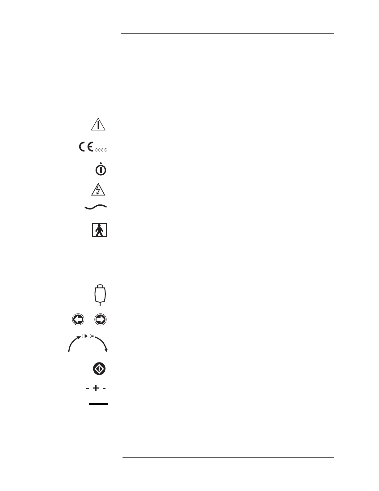
The following symbols are used on the MEDRAD Spectris Solaris EP Mobile
MR Injection System and components.:
Attention, consult accompanying instructions.
Indicates that this device conforms to the requirements of the European
Medical Device Directive 93/42/EEC.
Indicates on/off switch for the Control Room Unit.
Indicates hazardous voltages.
Indicates alternating current.
Identifies a type BF applied part complying with EN 60601-1 standards.
CLASS 1
IPX1
Indicates the injection system is Class 1 medical equipment as defined by
EN 60601-1 standards.
Identifies the degree of protection against fluid as drip proof for the
Spectris Solaris EP Injector system.
Identifies connection of the handswitch.
Identifies injector head forward and reverse piston control keys.
Identifies the direction of manual knob rotation relative to plunger
movement.
Identifies the ENABLE key.
Identifies polarity of the battery pack terminals.
Indicates DC power supply.
1 - 4
Page 9
1 - Introduction
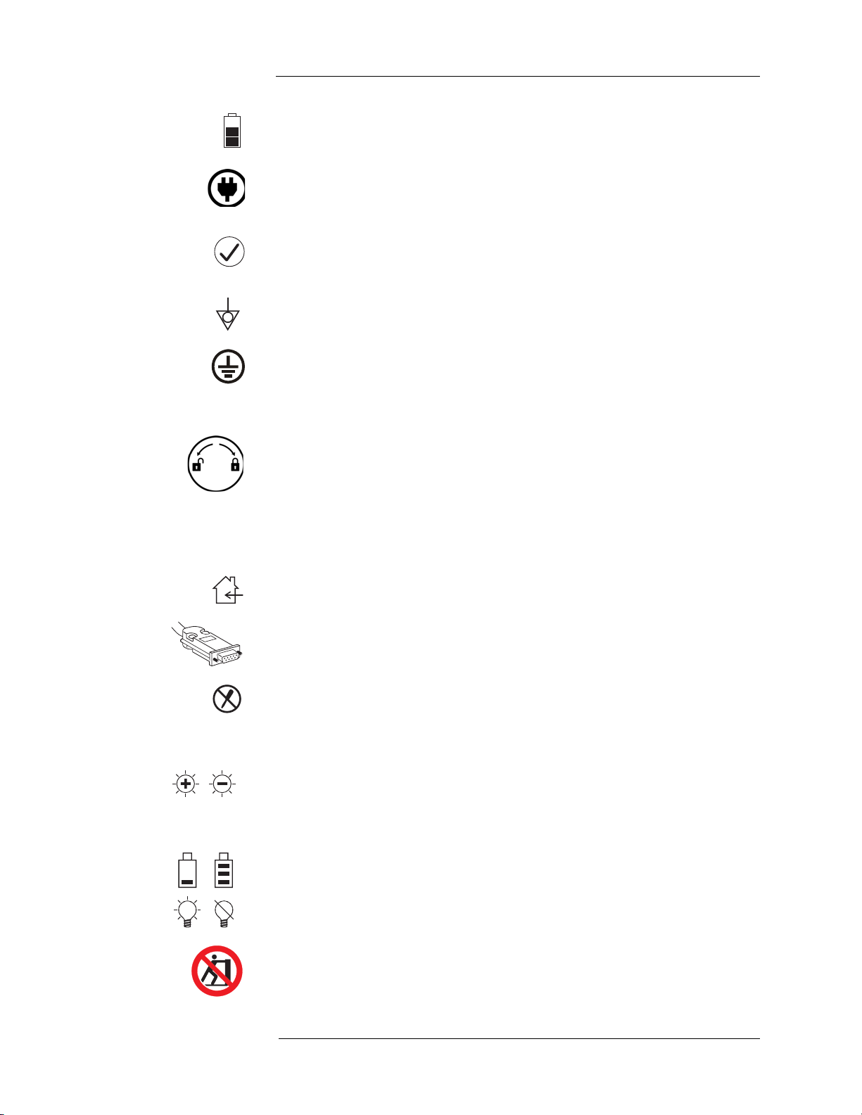
Indicates the current charge level of the system battery.
Identifies Integrated Continuous Battery Charger system activity on
Graphical User Interface. When illuminated yellow this indicates that the
Continuous Battery Charger system is present and functioning.
Indicates the AIR EXPELLED button on the injector head. When
illuminated yellow on the touch screen, also indicates that the operator has
acknowledged inspecting the fluid path for air.
Identifies the Equipotential connection.
Identifies the Earth Ground point.
IOIO
TX
RX
Identifies the Service Connection Port.
Identifies the Locking Bracket. Indicates which direction to turn Locking
Bracket knob to “lock” and “unlock” the bracket.
Identifies the Communication Cable Transmit connection.
Identifies the Communication Cable Receive connection.
Indicates design for indoor use only.
Identifies the Integrated Continuous Battery Charger System power supply
connection.
Indicates the presence of no serviceable parts.
I
Indicates the presence of AC power at the battery charger.
Identifies the Control Room Unit brightness controls.
P109
Reserved for future use.
Indicates the status of the battery charger. When a battery is properly
inserted, the LED will illuminate while charging, and extinguish when the
battery is fully charged.
Pushing Prohibited. Do not push at or above this point on the Injector.
1 - 5
Page 10
MEDRAD Spectris Solaris EP MR Injection System
This manual contains important information about use of the MEDRAD
Spectris Solaris EP MR Injection System.
MEDRAD urges you to read this manual carefully, become familiar with the
procedures and system functions that it describes, and follow its
recommendations to assure proper use of the system.
Labels on the system or statements in this manual preceeded by any of the
following words and/or symbols are of special significance, intended to help
you to operate the system in a safe and successful manner:
WARNING: Indicates that the information is a warning. Warnings
advise you of circumstances that could result in injury or death to the
patient or operator. Read and understand the warnings before
operating the injection system.
CAUTION: Indicates that the information is a caution. Cautions advise
you of circumstances that could result in damage to the device. Read
and understand the cautions before operating the injection system.
Note: Indicates that the information that follows is additional
important information or a tip that will help you recover
from an error or point you to related information within the
manual.
Warnings Patient injury may result from a system malfunction. If a system
malfunction occurs, immediately remove unit power (by pulling the battery
from the Scan Room Unit), and disconnect the unit from the patient. If a fault
message is displayed that cannot be corrected, and/or the system is not
operating correctly, do not use the injection system. Call MEDRAD for
assistance.
Patient injury could result from leaks or ruptures during an injection. To
prevent leaks or ruptures in the event of a blockage, use only catheters and
connectors with pressure ratings compatible with this system.
Explosion hazard. The MEDRAD Spectris Solaris EP MR Injection System is
not suitable for use in the presence of a flammable anesthetic mixture with air,
oxygen, or nitrous oxide.
Fire hazard. To avoid an electrical fire, assure the correct type of fuse is used
for replacement. The fuse must be replaced with Type F, 250 V, 2.5 A fuse by
qualified personnel only.
Electrical shock hazard. Hazardous voltages exist within system
components. Do not remove or open any enclosure.
Electrical shock hazard. Avoid fluid entry into system components. Do not
immerse any components in water or cleaning solutions. Use a damp cloth
when cleaning on or around the battery and the Integrated Continuous Battery
Charger system power supply.
Electrical shock hazard. Serious injury or death may result from exposure to
hazardous voltages existing within the system. Disconnect the Battery
Charging System from line power and remove the battery from the Scan
Room Unit before cleaning.
1 - 6
Page 11

1 - Introduction
Electrical shock hazard. Equipment must only be connected to a supply
mains with protective earth.
Ventilation hazard. To avoid a build up of hydrogen gas from the battery,
assure the room is well ventilated while battery is charging.
Improper disposal of the battery pack may result in explosion, leakage,
or personal injury. Do not open, or dispose of in a fire! Follow all local
regulations concerning the disposal of spent lead-acid based batteries, or
contact MEDRAD for assistance.
System electronic assemblies contain potentially hazardous materials.
Dispose of system components or accessories properly. Follow local
regulations for proper disposal or contact MEDRAD Service for assistance.
Unsafe operation may result from using improper accessories. Use only
accessories and options provided by MEDRAD designed for this system.
Chemical burn hazard. Always carry the battery pack firmly by the battery
pack hand grips. Damage to the housing may result in a chemical burn
hazard. Do not use if the housing is severely cracked or damaged.
Voltage hazard from worn cabling or unit disassembly. To avoid exposure
to potentially hazardous voltages, do not disassemble the injection system in
any way. Worn cabling also creates voltage hazards. If any worn or damaged
cables are detected, do not use the injection system. Contact MEDRAD for
service or replacement.
The MEDRAD Spectris Solaris EP MR Injection System is a dual syringe
system. Always ensure that the proper syringes are loaded with contrast
media and flush solution prior to the injection. Failure to properly load and
install the syringes may require the procedure to be repeated. Syringe A is
designated for contrast agent use only. Syringe B is designated for flush
solutions only.
Injury or equipment damage may result from use of tools containing
ferrous materials. Use only non-magnetic tools to install any scanner/
magnet room components.
Patient injury and/or catheter damage may result from using connector
tubing (LPCT) that is too short. Operator must consider tubing length and
stretch limitations when moving the injector or the patient.
Serious injury or death may result from syringe failure. Do not retract
pistons with connector tubing installed. Retracting the pistons with the
connector tubing installed on syringes will create a vacuum in the syringe due
to the check valve in the connector tubing. This vacuum may accelerate the
plunger rapidly toward the tip of the syringe when it is removed from the
injector causing the syringe to break.
1 - 7
Page 12

MEDRAD Spectris Solaris EP MR Injection System
Cautions Condensation may cause electrical damage to the injection system. Do
not use the system immediately after it has been brought indoors from
extreme outside temperatures. Allow the system to stabilize at room
temperature before use.
Injector may disarm or fail to operate upon exposure to high
electromagnetic fields that may be generated by radio transmitters or cellular
phones, or upon exposure to high levels of electrostatic discharge.
This injector system is in compliance to IEC-60601-1-2 / Second and
Third Edition Standards. Special precautions regarding ElectroMagnetic
Compatibility (EMC), are required for installation and use of this injector
system. Detailed EMC information can be found in the MEDRAD Injector
Service Manual - Addendum, (label number: 202559).
Damage can occur as a result of incorrect voltage. Before plugging in the
system, check the following:
• Verify that the voltage and frequency marked on the serial tag on
the back of the unit matches the voltage and frequency of the
electrical outlet.
• Verify that the Control Room Unit and the Battery Charger power
supply have the appropriate power cord plugs for the power
outlet.
Additional warnings, cautions, and notes are located throughout this manual,
where applicable.
1 - 8
Page 13
2 - System Basics
2 - System Basics
About the Injection System
The MEDRAD Spectris Solaris EP MR Injection System is a programmable,
dual syringe system, designed to accurately administer controlled doses of
intra-venous MR contrast agents and common flushing solutions to patients
undergoing a contrast enhanced MR scan.
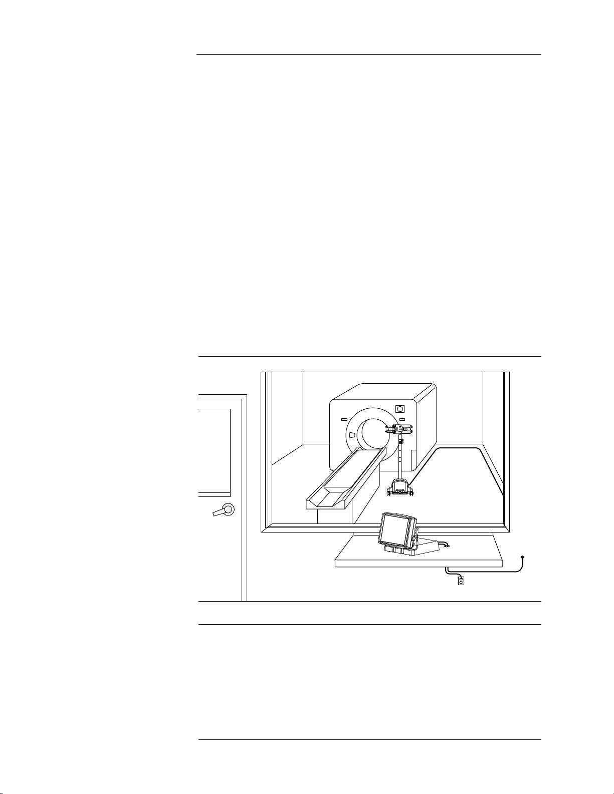
The system consists of two basic components that communicate by a direct
connection of fiber optic lines.
• The Control Room Unit houses the Touch Screen and electronic
components used to program the injection system.
• The Scan Room Unit, positioned near the magnet bore, contains
the Injector Head, system battery pack, and the mechanical
assemblies required for fluid delivery.
A battery charger is also supplied with the system, used to charge the Scan
Room Unit battery pack. For convenience, the charger can be used in the
control room, but should never be installed or operated in the scan room.
Note: Follow all institutional, local, or national safety regulations
related to routing cabling on the floor.
2 - 9
Page 14

MEDRAD Spectris Solaris EP MR Injection System
Pressure Safety Limit
Response to Occlusions
The MEDRAD Spectris Solaris EP MR Injection System is designed to allow
varied flow rates for contrast injections. By automatically reducing the flow
rate, the system can limit the pressure produced during an injection to prevent
damage or failure of any connecting devices or tubing. This feature is called
Pressure Safety Limit.
Inability to maintain the desired flow rate while remaining below the Pressure
Safety Limit can be caused by various conditions including contrast viscosity,
catheter sizing, connector tube sizing, and stopcock restrictions. If the system
is unable, for a period of three seconds, to maintain a flow rate of at least 10%
of the programmed rate, the system will disarm due to a stall condition.
If unable to automatically achieve the required level of flow rate reduction,
thus reaching the Pressure Safety Limit, the system will terminate the
injection and move to a disarm state.
When injecting into an occlusion, a stall condition (flow rate less than 10% of
programmed rate) will result. A stall condition lasting more than 3 seconds (3
minutes for programmed rates less than 0.1 ml/sec) will result in the injection
being automatically terminated.
If an occlusion occurs during KVO (Keep Vein Open) the system will detect
the condition after 4 or less KVO boluses fail to be delivered. This will
correspond to from 1 minute with a KVO interval of 15 seconds configured, to
5 minutes with a KVO interval of 75 seconds. Refer to the Setup screen to
determine the current KVO setting.
Volume and Rate Protection
If a stall occurs due to an occlusion, and the blockage is subsequently
removed, less than 10 ml will be delivered as the pressure in the
administration set dissipates.
The following means are provided to protect against over and under volume
or rate conditions:
• Warnings displayed on the Safety screen and during the arming
sequence remind the operator to check the programmed injection
parameters prior to the system being armed.
• An onscreen indication of insufficient volume is provided whenever the
total volume programmed to be delivered is greater than the amount of
fluid in the syringe.
• Injection monitoring is performed to detect over rate or over volume
conditions due to system faults. If either of these conditions is detected,
the injection will be stopped before an additional 10 ml of fluid above
programmed volume is delivered.
2 - 10
Page 15
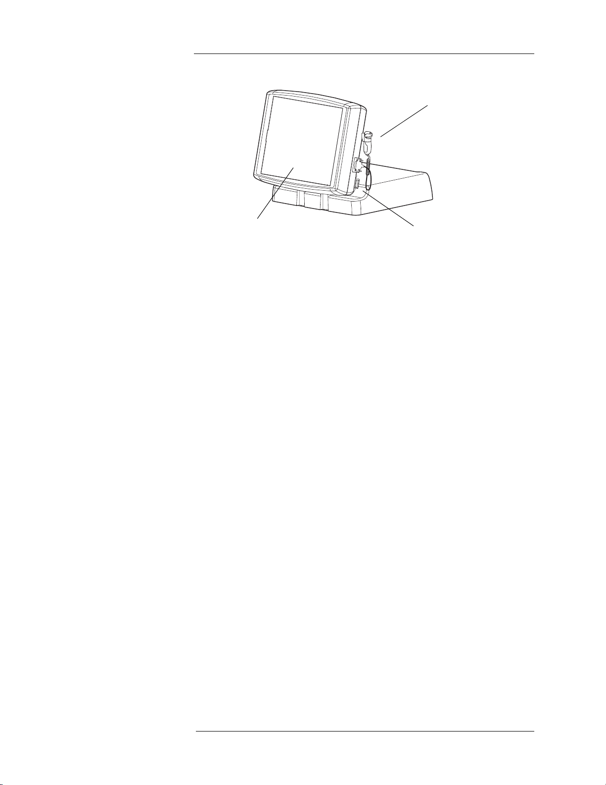
Control Room Unit
1
3
2
2 - System Basics
1. Handswitch
2. System Power Switch
3. Touch Screen
At rear of Touch Screen Assembly - Display Contrast Controls
2 - 11
Page 16
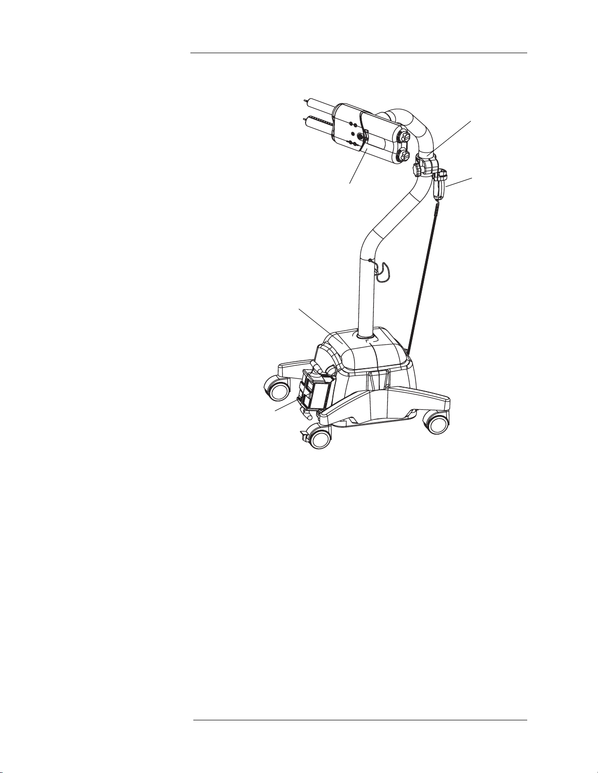
Scan Room Unit
1
3
4
2
5
MEDRAD Spectris Solaris EP MR Injection System
1. Injector Head
2. Handswitch
3. Lower Console
4. System Battery Pack
5. Middle Pivot Clamp
Not shown - Contrast Holder (optional)
2 - 12
Page 17
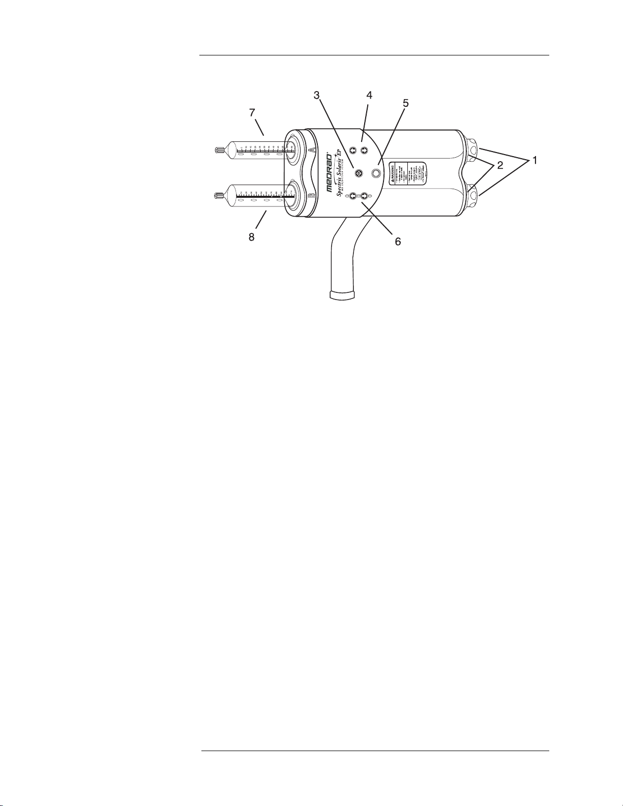
Injector Head
2 - System Basics
1. Manual piston movement knobs
2. Armed indicator lights
3. ENABLE button - Used to activate the forward/reverse controls - the
appropriate direction must be selected within 5 seconds.
4. Syringe A forward/reverse controls
5. AIR EXPELLED button/indicator
6. Syringe B forward/reverse controls
7. Syringe A: Contrast agent
8. Syringe B: Flush solution
2 - 13
Page 18
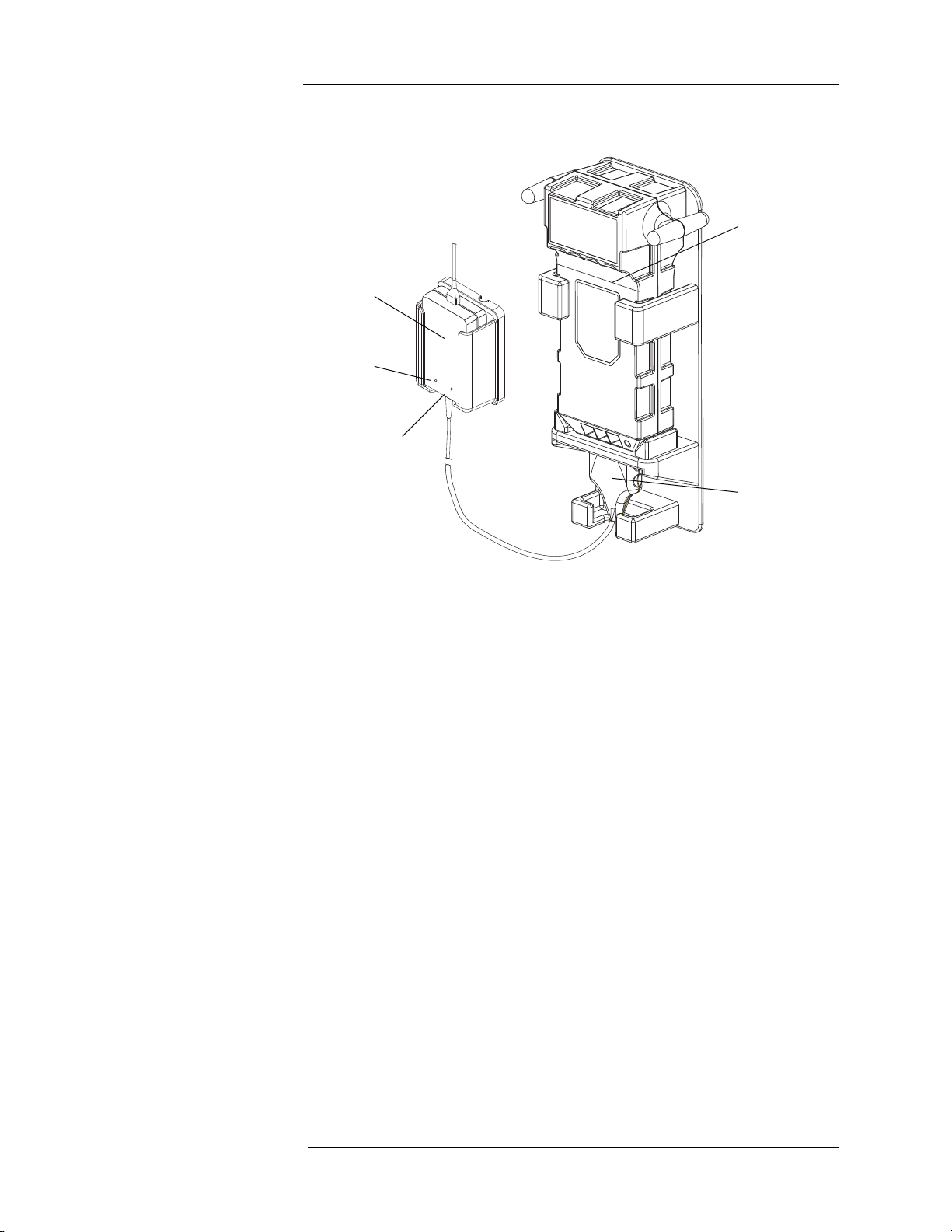
Battery Charger
1
3
4
5
2
MEDRAD Spectris Solaris EP MR Injection System
1. Battery Pack
2. Battery Charging Unit
3. Charging Indicator - Amber
4. Power Indicator - Green
5. Battery Charger Head
2 - 14
Page 19
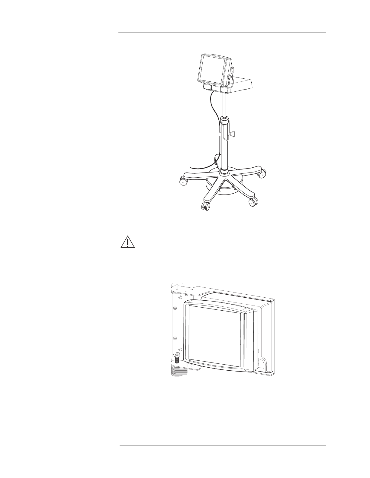
Optional Control Room Unit Accessories
2 - System Basics
Adjustable Height Pedestal
WARNING: Injury or equipment damage may result if the
adjustable height pedestal is taken into the scanner room. Do not
take the adjustable height pedestal in the scanner room. It
contains ferrous material that could be attracted toward the magnet.
Wall Mounting Bracket
Note: These accessories contain ferrous material and are
designed to be used in the Control Room only. Do not
install or operate in the Scan Room.
2 - 15
Page 20
MEDRAD Spectris Solaris EP MR Injection System
Touch Screen Calibration
To enter Touch Screen Calibration mode, simultaneously press both the
Contrast UP and DOWN keys on the rear of the touch screen housing. A
series of screens with instructions to press the appropriate calibration circles
will appear.
CAUTION: Do not touch the screen with a sharp object in order to
perform the calibration.
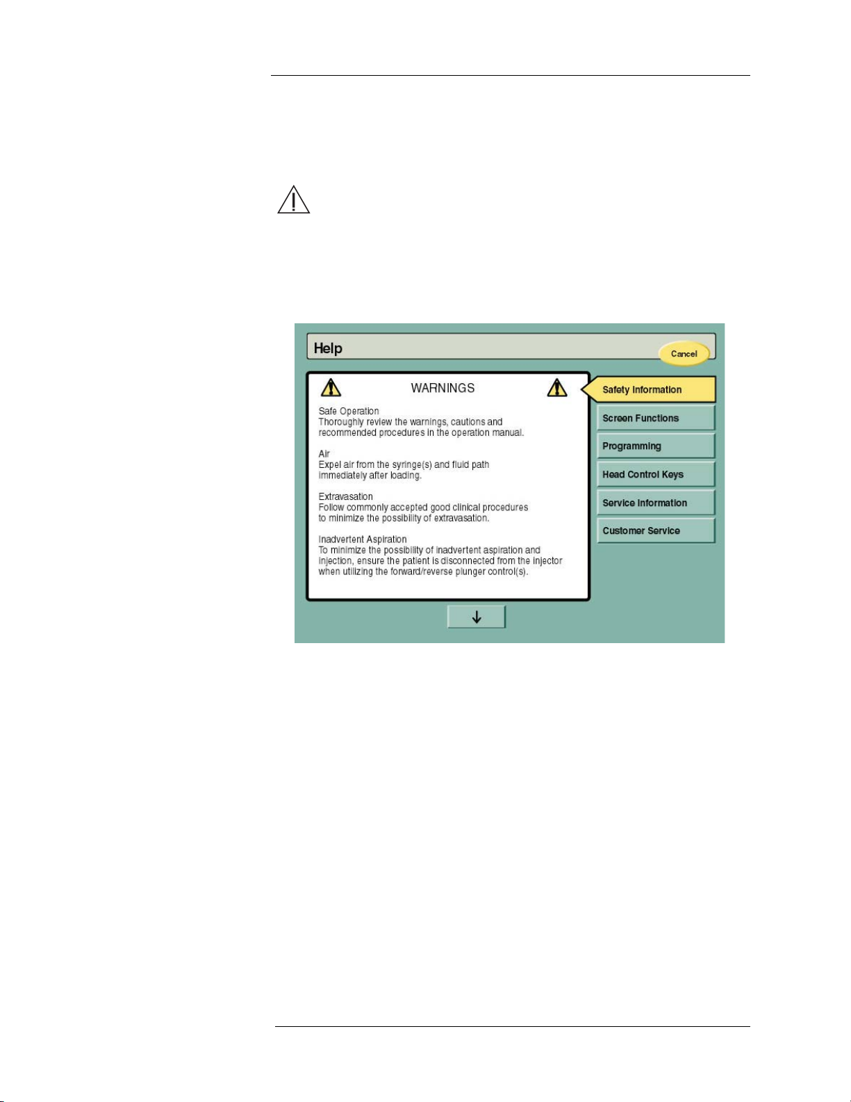
Help Mode The Help screen can be accessed by pressing the HELP button on the lower
right corner of the Main screen. Besides safety information, the Help screen
displays a variety of topics as displayed below.
2 - 16
Page 21
2 - System Basics
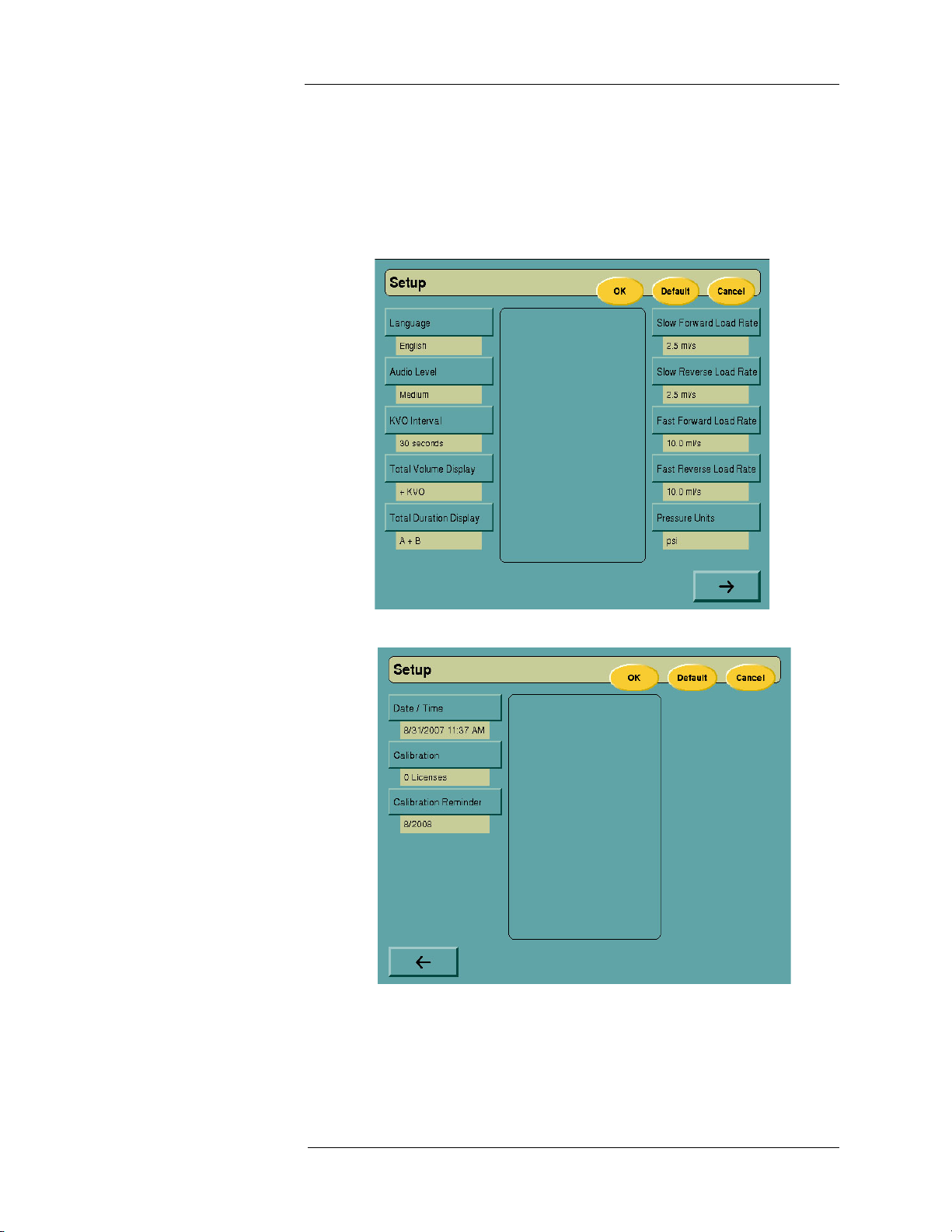
Setup Mode The Setup screen can be accessed by pressing the SETUP button at the
lower right corner of the Main screen. The Setup screen allows user
configurable options and preferences to be selected, along with setting of
date and time parameters.
Select the appropriate option, then choose from the available selections in the
display window. Select the DEFAULT key to return all options to original
factory settings.
The system provides a calibration and maintenance reminder. This reminder
will be displayed on the System Logo screen at each startup, beginning 30
days before the system is due to be recalibrated. The duration of time from
one calibration to the next is programmed during system installation or by
selecting the Calibration Reminder key and entering the correct due date.
2 - 17
Page 22

MEDRAD Spectris Solaris EP MR Injection System
2 - 18
Page 23

3 - Preparing to Inject
3 - Preparing to Inject
Applying Power Place the power switch located on the right side of the Control Room Unit in
the ON position. The System Logo screen will appear while the system
performs a series of self diagnostic tests.
Note: Do not touch the screen or activate any controls while
self diagnostics are in progress. If this occurs, diagnostic
tests will interpret this activity as a hardware failure and
halt the system. The system must then be powered
down/up to reset the error.
After diagnostics have successfully completed, the System Logo screen will
be replaced by the Safety screen
After reading the Safety screen, press CONTINUE to view the Main screen.
Apply power to the Scan Room Unit by inserting the battery into the
receptacle on the bottom of the Scan Room Unit. Upon power up of the CRU
and SRU, verify that the indicators, lamps, and speaker are operational.
Note: The Control Room Unit can be programmed for an
injection without power applied at the Scan Room Unit.
3 - 19
Page 24

MEDRAD Spectris Solaris EP MR Injection System
Main Screen The Main screen is entered from the Safety screen after power-up. The Main
screen is used during programming, arming, and injecting, with applicable
screen controls made visible based on the task currently being performed.
3 - 20
Page 25

3 - Preparing to Inject
Battery Maintenance WARNING: Explosion Hazard. Serious injury or death may result
from improper use of the battery charger. The battery charger,
MEDRAD Catalog Number 3012424, is intended for use in a well
ventilated area, with the injection system battery, MEDRAD Catalog
Number 3012070, only. Do not use the charger with non-rechargeable
batteries.
When the Main screen appears, check the status of the system battery in the
lower left corner of the screen. The battery icon will contain three horizontal
bars when indicating full charge, two when indicating medium charge, one for
low charge, and no indicators in the icon when the battery is fully depleted,
not connected, or communication is not detected between the Control Room
and Scan Room Units.
If the depleted battery is not replaced when only one bar is displayed, the
system will complete any injection that is in progress. However, the system
may not initiate a single or multi arm injection, the forward and reverse
controls on the injector head may not function and system communications
may be lost.
Each battery pack should last for 4 to 6 typical injections using a 20 minute
KVO, or approximately 5 hours in an idle state before requiring a recharge.
Monitor battery status per injection and on a daily basis. Each battery is
capable of being recharged approximately 300 times. When the life of a
battery pack becomes shortened, noticeably sustaining fewer injections per
charge, this signals that battery life is expiring and the battery pack should be
replaced. Call MEDRAD Service for battery pack replacement.
To charge the battery, place the 3-pronged, charging head into the battery,
then connect the charger to AC power. A green LED on the charger indicates
that AC power is applied. An amber LED indicates that the battery is charging.
The amber LED will turn off when full charge is reached. Battery charge time
is approximately 5 hours.
3 - 21
Page 26

MEDRAD Spectris Solaris EP MR Injection System
Syringe and Disposable Accessory Installation
Retracting the Pistons
Fully retract each piston by using the reverse switches on the injector head.
Note: When using the reverse switches, first press the Enable
switch; then within 5 seconds, press the reverse
switch(es). Both pistons may be reversed simultaneously.
The forward and reverse switches have dual speed capabilities:
When the switches are partially depressed, the pistons will move slowly.
When fully depressed, the pistons will move quickly. Forward and reverse
piston speeds are fully configurable (1 to 10 ml/sec) in the Setup mode.
The manual knobs may also be used to move the pistons in the forward or
reverse direction. Turn the knobs clockwise to advance the piston,
counterclockwise to retract.
3 - 22
Page 27

Installing a Syringe WARNINGS:
Patient or operator injury may result if damaged components are
used. Do not use damaged components. Visually inspect all
components before use.
Patient infection may result from the use of non-sterile
components. Maintain sterility of all disposable components. Do not
store pre-loaded syringes.
The use of single-use disposable devices on more than one
patient is a biological hazard. Do not reuse single-use disposable
components.
Patient injury could result if the syringe is not properly engaged.
Ensure the alignment marks on the syringe and injector head are
properly aligned, and the piston and plunger are interlocked. Improper
engagement may cause syringe damage or under-volume delivery.
CAUTION: Improperly engaged syringes may leak or be
damaged. Ensure proper engagement of syringe and injector. Syringe
and injector engagement points must align.
3 - Preparing to Inject
Note: Syringe A is intended for contrast media, and Syringe B
is intended for flushing solution only.
1. Align the flanges on the syringe with the notches in the injector head.
(The syringe is keyed to properly fit in only one way.)
2. Insert the syringe.
3. Twist 1/4 turn clockwise until the syringe snaps into place. (Graduations
will be facing the front of the injector head.)
3 - 23
Page 28

MEDRAD Spectris Solaris EP MR Injection System
Fig. 1 Empty
Fig. 2 Filled
WARNING: Air embolism can cause patient injury or death. Expel
all trapped air from the syringe(s), connectors, tubing, and catheterover-needle before injecting.
Note: Do not hit or tap the syringe to remove air bubbles.
To reduce the volume and size of air bubbles drawn into the syringe during
loading, a MEDRAD Fluid Dispensing Device (FDD or “spike”) is
recommended. Air removal from the syringe(s) will be much more difficult if a
small diameter tube, such as a catheter-over-needle, needle, or a tube longer
than 10 inches (25 cm), is used for loading.
Operator vigilance and care, coupled with a set procedure, is essential to
minimizing the possibility of an air embolism. The injector head should be
pointed upward during loading, enabling any air to accumulate at the syringe
tip and to be expelled. The injector head should be pointed downward during
an injection, enabling any small air bubbles which could still be in the fluid to
float to the rear of the syringe(s).
To help avoid air injection, MEDRAD syringes are equipped with FluiDot indicators. These FluiDot indicators should be observed as part of an arming pro-
cedure. When the FluiDot is viewed through an empty syringe, the dots
appear as small narrow ellipses as illustrated below in figure 1. However,
when viewed through a full syringe, the dots become larger, almost round (or
wider than round) as illustrated below in figure 2.
FluiDot indicators must be viewed in a properly illuminated environment, with
a light source behind the operator providing enough light to permit easy
viewing.
To minimize air embolization risks, ensure that one operator is designated the
responsibility of filling the syringe(s). Do not change operators during the
procedure. If an operator change must occur, ensure that the new operator
verifies that the fluid path is purged of air.
WARNING: If a blockage occurs, disposable components with a
lower pressure rating may leak or rupture. Use only catheter and
connectors with ratings that are compatible with the MEDRAD
Spectris Solaris EP MR Injection System.
During installation of the low pressure connector tubing (LPCT) with Tconnector to the syringe(s), and before arming, manually advance the syringe
plunger(s) to provide a very slow flow of fluid at the connection. An absence of
flow is an obvious indication of air or a blockage in the fluid path.
3 - 24
Page 29

Loading a Syringe WARNIN GS:
1. Position the injector head so that the syringes are
pointing upward.
2. Fully advance each piston plunger. The plungers
may be advanced simultaneously after pressing
ENABLE.
3. Attach a sterile filling device (spike or Female-toFemale Adaptor - MEDRAD Catalog Number FFA
50) onto the tip of the syringe. If loading contrast
media and/or saline from a bag or bottle, use a
spike. If loading contrast media from a pre-filled
syringe, use an FFA 50.
A. If using a spike, open the bottle(s) of contrast
and/or bag(s) of flushing solution, then draw the
contents (contrast for syringe A; flush for syringe B)
into the syringe(s) by depressing ENABLE, and
then the reverse load button for each syringe.
B. If using the FFA 50, attach it to the tip of syringe
A, then attach the pre-filled syringe to the FFA
50. Draw the contents from the prefilled syringe
into syringe A by pressing ENABLE, then the
reverse load button.
4. With the filling device still attached, advance the
plunger to expel any air that may remain in the top
of the syringe; then, if necessary, draw more fluid
into the syringe to replace fluid loss.
5. Remove the filling device and expel any air bubbles
from the syringes.
Remove all trapped air from the syringe, connector tubing, and
catheter-over-needle before connecting the patient to the injector.
Syringe sterility will be compromised, and patient infection may
result, if the plunger is removed from the syringe. Do not remove the
plunger to fill the syringe.
Bacterial contamination can occur if syringes are used to store
contrast media. Use loaded syringes immediately. Do not store loaded
syringes for later use. Discard any unused syringes.
Note: The presence of rounded FluiDot indicators does not
indicate the total absence of air bubbles in the syringe tip.
Note: FluiDot indicators must be viewed in a properly
illuminated environment, with a light source behind the
operator providing enough light to permit easy viewing.
3 - Preparing to Inject
3 - 25
Page 30

MEDRAD Spectris Solaris EP MR Injection System
6. Attach the long end of the T-connector to
syringe B.
7. While the injector head is still in a vertical
position, attach the short section of the Tconnector to syringe A.
8. Starting with syringe A, then syringe B,
prime the T-connector, then fill the
connector tubing with the appropriate
fluid. Ensure that all air is expelled from
the entire length of the tubing.
Saline Flush Contrast
Note: A MEDRAD SSIT 96VLD low pressure connector tube
(LPCT) holds approximately 7 ml of fluid. If syringe B is
used to flush, use at least 8 ml of flush to deliver this
volume to the patient.
Note: If the connector tube is filled with saline, contrast will be
delivered to the patient with a delay dependent on the
flow rate selected for syringe A.
Note: When the connector tube is filled with contrast the
volume remaining displayed on the protocol screen is
approximately 7 ml less than what was loaded into the
syringe.
9. Tilt the injector head downward before attaching to the vascular entry
device in the patient. After attaching the connector tube to the vascular
entry device verify that the connector luer fittings are secured. The
injector head must be maintained in this position during the injection.
WARNINGS:
Patient injury could result from movement of the Scan Room Unit
after the patient is connected to the fluid path. Lock the casters at
the base of the unit and the Middle Pivot Clamp to prevent unintended
movement.
Patient injury and/or catheter damage may result from using
connector tubing (LPCT) that is too short. Operator must consider
tubing length and stretch limitations when moving the injector or the
patient.
10. Secure the Scan Room Unit by locking the casters and the Middle Pivot
Clamp, then verify that all air has been expelled from the fluid path by
carefully inspecting all tubing and syringe(s). Acknowledge that the
inspection has occurred by pressing the AIR REMOVED confirmation
button/indicator on the injector head. The Air Removed Indicator will then
illuminate yellow on the touch screen.
Note: Reverse movement of the pistons after the AIR
EXPELLED button has been pressed will cancel the Air
Expelled status. Re-check the fluid path for air, then
press the AIR EXPELLED button again to continue.
3 - 26
Page 31

3 - Preparing to Inject
1. Insert the end of the syringe in
the horizontal cutouts in the
injector head.
2. Advance the piston until it is
past the plunger feet and the
piston/plunger interlock.
3. Rotate the syringe 1/4 turn
clockwise until the syringe
locks and alignment marks are
positioned.
4. Proceed as normal by
aspirating and dislodging any
air bubbles.
Reinstalling a Syringe
WARNING: Patient injury could result if the syringe is not
properly engaged. Ensure the alignment marks on the syringe and
injector head are properly aligned, and the piston and plunger are
interlocked. Improper engagement may cause syringe damage or
under-volume delivery.
If you remove a syringe from the injector, and then wish to reinstall it, perform
the following steps:
Note: If bubbles appear in the syringe DO NOT hit the syringe
to remove them. Reverse the plunger 3 to 5 ml, then rock
the head on the pivot to gather and accumulate the small
bubbles. Expel the remaining air.
3 - 27
Page 32

MEDRAD Spectris Solaris EP MR Injection System
Programming
If a program has not been previously entered or stored on the Main screen
when the unit is powered up, the Main screen will display default settings; 1.0
ml/s flow rate and 1.0 ml volume, KVO off and No Delay.
Flow Rate and Volume
Begin programming by selecting any programmable block, such as FLOW
RATE or VOLUME. When a programmable block on the screen is touched, a
keypad will be displayed to permit the selection of numeric values. The
numeric keypad is displayed when a Flow Rate, Volume or Delay value is
selected. The keypad window will also display the appropriate programmable
range for the parameter selected. To lock in values, press ENTER. Press <<
to edit a selection, or CANCEL to eliminate a selection if an error is made.
Pressure Limit The pressure limit can be programmed by choosing a value between 100-325
PSI up to the greater of the syringes’ maximum pressure.
3 - 28
Page 33

3 - Preparing to Inject
Multiple Phases If appropriate, select a second phase for the injection protocol by pressing the
triangle block below the first phase of the injection. The Phase Type selector
will appear in order to select the function of the new phase.
Hold and Pause Phases
A Hold or Pause phase can be programmed into a multi-phase injection. A
Pause phase will stop the total injection process for a preprogrammed length
of time, while the Hold phase will stop the injection until input from the
operator resumes the injection. A Hold phase can be maintained for up to 20
minutes, at which time the system will disarm.
After selecting the phase type, continue programming by entering Flow Rate
and Volume values for the new phase.
3 - 29
Page 34

MEDRAD Spectris Solaris EP MR Injection System
Programmed Delay After entering Flow Rate and Volume parameters, press SET in the Delay
Timer field to select the delay type (Scan Delay, Inject Delay, Stopwatch, or
No Delay.)
Note: There is no direct interface between the scanner and the
injector. The scanner cannot trigger the injector, nor can
the injector trigger the scanner.
Scan Delay Scan Delay time will elapse in the timer block on the screen. The time
remaining before the scan should be activated will decrement in one second
intervals. (The scan delay countdown will continue through multiple arm
injections.) When countdown is complete, the system will emit 5 beeps.
Inject Delay Inject Delay will also countdown in one second intervals, commencing when
the handswitch is pressed. The clock will display, in one second decrements,
the time remaining before the injection will begin. When inject delay is chosen
and the handswitch is pressed, the injection will automatically occur unless
the injector is disarmed. When countdown is complete, the system will emit 5
beeps and the injection will automatically begin.
If Hold is activated during an inject delay or a scan delay, the timer will stop
during the hold interval and resume when the handswitch is pressed.
For scan or inject delays that are longer than 3 minutes, the unit will beep 30
seconds before the delay is to terminate, then will beep every second from 5
seconds through 1 second before the delay is due to terminate.
3 - 30
Page 35

3 - Preparing to Inject
15 seconds
20 seconds
30 seconds (default)
45 seconds
60 seconds
75 seconds
Stopwatch The Stopwatch function initiates an incremental count of elapsed time from
initial fluid injection.
After selecting the delay type, enter the delay duration on the numeric keypad.
To lock in values, press ENTER. Press CANCEL to eliminate a selection if an
error is made.
KVO (Keep Vein Open)
The KVO function delivers small boluses of fluid from syringe B at
configurable intervals. KVO can run during:
• Programming
• Pre and post injection
• Between multiple injections
• During Pause and Hold
The delivery interval can be selected in the Setup mode, which is accessed
using the Setup button on the Main Screen.
After an initial KVO pulse of 2 ml, KVO delivery intervals include 0.25 ml
pulsed every:
3 - 31
Page 36

MEDRAD Spectris Solaris EP MR Injection System
The KVO field displays the time available to support
KVO based on the configured interval and the volume
remaining in syringe B less any volume programmed
from syringe B in the protocol.
Starting KVO:
On the Main Screen, press START in the KVO field to initiate KVO. When
KVO is running, “KVO” will appear, and the KVO Injecting arrows will flash in
the Syringe B touch screen indicator.
KVO will function during Pause, Hold and/or inject delay periods. KVO will
resume post-injection until no fluid remains in syringe B, or until STOP KVO is
pressed in the Injection Complete window.
Note: Volume displayed in the Volume Delivered window can
be configured in the Setup mode to include the total KVO
volume delivered in addition to volume delivered by the
programmed injection.
KVO may be stopped at any time by pressing STOP in the KVO field, or by
pressing any injector head control button (this will also disarm the system and
terminate any injection in progress). Other actions that disarm the injector,
such as syringe removal, disarm button press and injection stall, will also stop
KVO.
KVO and Occlusions
If an occlusion occurs during KVO the system will detect the condition after 4
or less KVO boluses fail to be delivered. This will correspond to from 1 minute
with a KVO interval of 15 seconds configured, to 5 minutes with a KVO interval of 75 seconds. Refer to the Setup screen to determine the current KVO
setting.
:
3 - 32
Page 37

3 - Preparing to Inject
Storing a Protocol To store a protocol for future use, press the STORE button on the upper right
corner of the Main screen.
An alpha-numeric keypad will appear with a flashing cursor in the title block.
Type in a title of up to 20 characters, including spaces. Use the arrow key to
backspace, individually erasing characters, and the CLEAR key to clear a
string of text. When title entry is completed, press ENTER.
To exit the Store screen without making changes, press the CANCEL button
in the upper right corner.
3 - 33
Page 38

MEDRAD Spectris Solaris EP MR Injection System
Recalling a Stored Protocol
To access program memory, press RECALL on the Main screen.
Select a previously stored injection protocol by pressing one of the names on
either side of the screen. Key parameters of the selected injection will be
displayed in the center of the screen. Once selected, the protocol can be
deleted by selecting DELETE at the upper right corner of the screen, or
brought to the Main screen by selecting OK.
3 - 34
Page 39

4 - Arming and Injecting
4 - Arming and Injecting
Before beginning the arming process, ensure that the casters on the Scan
Room Unit are locked, verify that all air has been expelled from the fluid path,
and that the programmed parameters are correct. Carefully inspect all tubing
and syringe(s), then acknowledge that the inspection has occurred by
pressing the AIR EXPELLED button/indicator on the injector head. A yellow
illuminated Air Expelled Indicator on the touch screen confirms that the button
has been pressed.
WARNINGS:
Air embolization can cause death or serious injury to the patient.
Do not connect a patient to the injector until all trapped air has been
cleared from the syringe and fluid path.
Patient injury could result from high flow rate venous injections.
Use extreme care when selecting flow rate and duration. Before
arming the injector, verify that high flow rate injection parameters have
not been unintentionally programmed.
Patient injury could result from inadvertent aspiration. To
minimize the possibility of inadvertent aspiriation and injection, ensure
the patient is disconnected from the injector when utilizing the forward/
reverse plunger control(s).
Extravasation can cause injury to the patient. Follow commonly
accepted good clinical procedures to minimize the possibility of
extravasation.
Arming To begin the arming and injecting process, press ARM on the Main screen. If
necessary, changes can be made to programmed injection parameters after
the arming sequence is complete. Select the required parameter, then enter
the correct value with the on-screen keypad. Pressure safety limit programmed by the user is indicated to the user and cannot be changed when
the injector is armed.
Note: If the AIR EXPELLED button on the injector head has not
been pressed, the system will request user confirmation
that air has been expelled before proceeding.
Single and MultiArm
Select either a Single or Multiple arming sequence by pressing either SINGLE
or MULTI. (The default is Single arm.)
A single arm injection will perform the protocol once, then disarm.
A multi-arm injection allows the protocol to be repeated, creating a series of
injections. After the protocol is completed, the system will automatically rearm in preparation for the protocol to be repeated. Each injection in the series
must be started with the handswitch.
4 - 35
Page 40

MEDRAD Spectris Solaris EP MR Injection System
Insufficient Volume If an insufficient volume condition occurs during a multi arm sequence, the
system will remain armed to permit the injection of the remaining volume.
However, the screen will update to display only the phases that are
achievable with the volume that remains. In a single arm sequence, the
screen will update when arming occurs to display only the phases that are
achievable.
While the system is armed, pressing DISARM or activating any injector head
controls will return the system to the idle state.
Injecting After the system has been armed, press the handswitch to begin the injection.
Additional presses of the handswitch will alternately “hold” and resume the
injection. The maximum duration for Hold is 20 minutes. If the maximum hold
time is exceeded the injection will abort automatically.
If an inject delay has been programmed, pressing the handswitch will
activate the countdown timer. The programmed injection will automatically
begin when the timer counts down to zero. If the handswitch is pressed during
an inject delay, the countdown timer will stop counting until the switch is
pressed again, or the Hold time is exceeded.
If a scan delay is programmed, the scan delay countdown and the injection
will start simultaneously. During the injection, additional presses of the hand
switch will alternately “hold” and resume the injection and the scan delay
timer.
If KVO is running: KVO will function during Pause, Hold and/or inject delay
periods as long as sufficient fluid remains in syringe B to complete the
programmed injection. KVO will run post-injection until no fluid remains in
syringe B, or until STOP KVO is pressed in the Injection Complete window. To
stop KVO the operator can also press any injector head control buttons.
If a Hold phase is entered, parameters for the remaining portion of the
injection protocol can be altered.
4 - 36
Page 41

4 - Arming and Injecting
On the Injecting Screen:
• As each phase is activated, the phase parameters will be highlighted to
display injection progress.
• The Duration window will also increment to display elapsed time.
• The Delivered window will increment as the injection proceeds to display
volume delivery (including KVO volume, if selected in Setup mode).
• The Volume Remaining display will decrement.
• The Programmed pressure limit and the current pressure will be indicated
on the display. If a pressure limit condition occurs, it will indicate on the
display.
• If KVO is selected, the time available for KVO will decrement in the KVO
Time Remaining window while KVO is active. (During an injection, KVO
will stop and the time display will not count-down.)
On the Injector Head
• While injecting, indicator lamps on the back of the injector head will be
illuminated (white for syringe A, blue for syringe B). The appropriate
lamps will be lit solid while injecting, and flash while either Armed or on
Hold.
• If multi-arm is selected, the indicator lamps will flash when the system
rearms.
• During KVO the blue indicator lamp for syringe B is illuminated.
• AIR EXPELLED Indicator is illuminated.
:
Disarming Pressing DISARM, activating any injector head controls, or touching any
portion of the touch screen while the system is injecting, will cause the system
to disarm.
The Hold mode can be entered at any time during an injection by pressing the
handswitch. The system will remain in this state until the handswitch is
pressed a second time, or the maximum hold time of 20 minutes is exceeded.
4 - 37
Page 42

MEDRAD Spectris Solaris EP MR Injection System
Note: A MEDRAD SSIT 96VLD low pressure connector tube
(LPCT) holds approximately 7 ml of fluid. If syringe B is
used to flush, use at least 8 ml of flush to deliver this
volume to the patient.
Note: If the connector tube is filled with saline, contrast will be
delivered to the patient with a delay dependent on the
flow rate selected for syringe A.
Note: When the connector tube is filled with contrast, the
volume remaining displayed on the screen is
approximately 7 ml less than what is present in the
system.
When an injection (single or all multi-arm sequences) is completed, the
following window, with a brief summary of the injection parameters, will be
displayed.
4 - 38
Page 43

4 - Arming and Injecting
Injection History To review injection parameters used in a procedure, along with actual
achieved values for the injection, press the HISTORY button on the Main
screen.
The Injection History screen displays an injection summary block containing
the following data:
• Time and Date Started
• Programmed Flow Rate
• Programmed Volume
• Programmed Protocol
• Total Fluid (plus KVO)
• Delay Type
• Delay Duration
• Pressure Limit Programmed
• Peak Pressure
• Pressure Limit Status (YES/NO)
• Premature Termination Status (YES/NO)
The system maintains status information of the 20 most recent injections,
sorted by date and time.
To delete any injection protocol history from the system, press DELETE while
the protocol is selected. To scroll to the next page of protocols, press the
ARROW key. To exit the Injection History screen, press CANCEL.
4 - 39
Page 44

MEDRAD Spectris Solaris EP MR Injection System
Clean Up Note: Do not resterilize or reuse any disposable items.
When cleaning the injector, remove and discard all used disposable items.
(Syringes should be removed without retracting the pistons.) It is not
necessary to remove the connector tubing when removing and discarding
syringes.
WARNING:
Serious injury may result from syringe failure. Do not retract
pistons with connector tubing installed.
• Disconnect the Control Room Unit from line power and remove
the battery from the Scan Room Unit before cleaning.
• Avoid fluid entry into system components. Do not immerse any
components in water or cleaning solution.
• Do not remove any covers or disassemble the injector.
Periodically inspect for loose or frayed cables, loose covers,
cracks, dents, or loose hardware. Contact MEDRAD Service for
repairs.
• Retracting the pistons with the connector tubing installed on
syringes will create a vacuum in the syringe due to the check
valve in the connector tubing. This vacuum may accelerate the
plunger rapidly toward the tip of the syringe when it is removed
from the injector causing the syringe to break.
CAUTIONS:
System malfunction may be caused by failure to perform regular
maintenance. Regular preventive maintenance is recommended to
ensure that the system stays calibrated and functions properly. Refer
to Appendix B of this manual or contact MEDRAD for additional
information.
Do not expose system components to excessive amounts of
water or cleaning solutions. Wipe components with a soft cloth or
paper towel dampened with cleaning solution.
Do not use strong cleaning agents and solvents. Warm water and
a mild disinfectant are all that is required. Do not use strong industrial
cleaning solvents such as acetone.
Note: For all body fluid spills, follow institutional
decontamination procedures.
Note: If contrast medium has leaked inside any component of
the system, the affected subassembly should be
disassembled and cleaned by MEDRAD Service
personnel or returned to MEDRAD Factory Service.
4 - 40
Page 45

4 - Arming and Injecting
Scan Room Unit Using a soft non-abrasive cloth, warm water, and a mild disinfectant, carefully
clean the assembly, paying particular attention to the following:
• Injector Head
• Syringe Piston Plunger
• Syringe Interface
• SRU Lower Console covers
To clean the injector head, piston, and syringe interface
1. Fully advance the piston.
2. Remove the battery from the Scan Room Unit.
3. Place the injector head in a vertical position.
4. Clean the piston with a soft cloth or paper towel dampened with cleaning
solution.
5. Thoroughly dry the piston with a paper towel.
6. Re-install the system battery, then fully retract the piston.
7. Remove the battery from the Scan Room Unit again.
8. Clean the inner area of the syringe interface with a soft cloth or paper
towel dampened with cleaning solution.
9. Wipe the injector head case and control panel with a soft cloth or paper
towel dampened with cleaning solution.
10. Thoroughly dry the injector head case and control panel with a paper
towel.
:
Control Room Unit CAUTION: Do not spray cleaning solutions directly onto the
touch screen. To prevent damage, wipe the touch screen with a soft
non-abrasive cloth or paper towel dampened with cleaning solution.
4 - 41
Page 46

MEDRAD Spectris Solaris EP MR Injection System
4 - 42
Page 47

Appendix A: System Messages
Appendix A: System Messages
The system will display messages on the screen as conditions or events
occur. There are three basic types of messages:
WARNING: Patient injury may result from a system malfunction.
If a system malfunction occurs, immediately remove Scan Room Unit
power (by pulling the battery from the head stand), and disconnect the
system from the patient. If a fault message is displayed that cannot be
corrected, and/or the system is not operating correctly, do not use the
injection system. Call MEDRAD for assistance.
Type 1 Messages Type 1 messages are messages which provide information regarding the
current status of the system, and will clear automatically from the screen.
These messages are typically displayed in the lower right corner of the
screen.
A - 43
Page 48

MEDRAD Spectris Solaris EP MR Injection System
A
System Error Detected
Immediately disconnect the patient from the injector.
Record the code below and contact MEDRAD Service.
Refer to the operation manual or www.Medrad.com for contact information.
Symcode = HSW
Errnum = -2600
Type 2 Messages Type 2 messages are messages that convey information that must be
explicitly acknowledged before proceeding. The message is displayed within
a yellow dialog box - a button (or buttons) must be pressed to acknowledge
and remove the message from the screen.
Type 3 Messages Type 3 messages are system malfunction messages which require power to
be removed from the system. Some Type 3 messages provide suggestions to
prevent the condition from recurring. If the condition cannot be corrected,
record the code and number from the lower left corner of the dialog box, then
call MEDRAD Service for assistance.
A - 44
Page 49

Appendix B: Maintenance and Checkout
Appendix B: Maintenance and
Checkout
This section contains recommended procedures for maintenance, and an
operational checkout of the MEDRAD Spectris Solaris EP MR Injection
System. Routine maintenance and inspection will:
• Ensure continued performance of the injection system
• Reduce the possibility of equipment malfunction
Recommended Maintenance Schedule
Your MEDRAD Spectris Solaris EP MR Injection System must be properly
maintained to ensure that it is in peak operating condition. Your individual
maintenance system and schedule depends upon how your injection system
is used, the type of procedures performed, and frequency of use. The
following maintenance schedule is recommended for the system:
Daily:
The piston rod should be thoroughly cleaned after each use. Before use each
day, the system should be cleaned and inspected, using the procedures
outlined in this section. Ensure that all system safety and warning labels are in
place and are legible.
Monthly:
Once a month, the entire system should be thoroughly inspected and
cleaned, and an Operational Checkout should be performed.
Annually:
As part of an annual maintenance program performed by a qualified
MEDRAD Service Representative or authorized dealer, both Electrical
Leakage and Ground Continuity checks should be performed.
NOTE: Local regulations or hospital protocol may require
electrical leakage checks at more frequent intervals. If
this applies, local regulations for leakage must be
followed.
MEDRAD also recommends that a complete system calibration and
performance checkout be performed annually. Contact MEDRAD Factory
Service, or your local MEDRAD office for complete details.
In the United States, Canada, and Europe, the MEDRAD Service Department
offers Preventive Maintenance Programs. These annual programs greatly
assist in maintaining accuracy and reliability, and can also extend the life of
the system. Contact MEDRAD for details. In Europe, contact your local
MEDRAD office or your local authorized dealer for further information. Refer
to the back of the title page of this manual for address, telephone and FAX
information.
B - 45
Page 50

MEDRAD Spectris Solaris EP MR Injection System
NOTE: Failures which occur due to lack of proper maintenance
will not be covered under warranty.
MEDRAD Service MEDRAD Service will make available upon request:
• Circuit diagrams, component parts lists, or other information that will
assist qualified technicians to repair components classified as repairable.
• On-site consulting or consulting references upon request.
Inspection Procedures
The following procedures are recommended for daily inspection of all
components in the MEDRAD Spectris Solaris EP MR Injection System. If any
defects are detected, either repair the system, or call MEDRAD for service.
Do not use the system until the problem is corrected.
Scan Room Unit 1. Inspect the housing for any damage or cracks that could allow fluid to leak
inside, or weaken the structural integrity of the unit.
2. Inspect all cables connected to the unit: Look for cuts, cracks, worn spots
or other obvious damage to the cables. Ensure that all connectors are
properly seated.
3. Inspect for contrast media build-up in the syringe interface area. Follow
the cleaning guidelines outlined in this section.
4. Inspect the stand, base, and support arm for cracks and other defects that
could weaken the structure.
5. Ensure that all mounting bolts and screws are secure.
6. Ensure that all locking mechanisms on the casters are functional.
7. Inspect the pivot points. The head and support arm must pivot freely. The
injector head should rotate on the support arm no more than 330
support arm should not rotate on the center post more than 350
NOTE: All relevant guidelines for institutional, local, or national
safety recommendations related to cable routing and
installation should be followed.
o
o
.
. The
Control Room Unit 1. Inspect all cables connected to the unit: Look for cuts, cracks, or worn
spots, or other obvious damage. Ensure that all connectors are properly
seated.
2. Inspect the housing for any damage or cracks that could allow fluid to leak
inside, or weaken the structural integrity of the unit.
B - 46
Page 51

Appendix B: Maintenance and Checkout
Wall Mount Bracket 1. Inspect all parts of the bracket for cracks and other defects that would
weaken the assembly.
2. Ensure that the bracket is securely attached to the wall.
3. Ensure that all cables are secured to the display control unit and do not
interfere with the movement of the mounting bracket.
Height Adjustable
Pedestal
1. Inspect the stand, base and support arm for cracks and other defects that
could weaken the structure.
2. Ensure all mounting bolts and screws are secure.
3. Ensure that the casters roll smoothly with no binding or scraping.
4. Ensure all locking mechanisms on the casters are functional.
5. Verify that the vertical height adjustment of the column shaft moves freely
without binding or scraping.
Battery Charger 1. Inspect all cables connected to the unit: Look for cuts, cracks, or worn
spots, or other obvious damage. Ensure that all connectors are properly
seated.
2. Inspect the housing for any damage or cracks that could allow fluid to leak
inside, or weaken the structural integrity of the unit.
3. Inspect all parts of the wall mounting bracket for cracks or other defects
that would weaken the assembly. If applicable, ensure that the bracket
remains firmly attached to the wall.
Communication Link 1. Inspect the cables for cuts, cracks or worn spots. Ensure that the
connectors are properly seated.
B - 47
Page 52

MEDRAD Spectris Solaris EP MR Injection System
Cleaning Guidelines
Deposits of contrast media can interfere with proper operation of the
MEDRAD Spectris Solaris EP MR Injection System. The following guidelines
should be followed when removing deposits, or cleaning any portion of the
system.
WARNING: Serious injury or death may result from exposure to
hazardous voltages existing within the system. Disconnect the
system from line power before cleaning or attempting to perform any
maintenance. Ensure that the system is completely dry before
connecting to the power source and applying power.
CAUTION: Improper or careless cleaning methods may result in
equipment damage. Do not soak or immerse any part of the injection
system in water. While cleaning any outside portion of the system,
avoid allowing any water to leak inside system components.
• If contrast medium has leaked inside any component of the system, the
affected subassembly should be disassembled and cleaned. This
cleaning procedure can be done in the field by trained MEDRAD Service
personnel, or returned to MEDRAD Service. If the cleaning will be
performed in the field, do not disturb any internal wiring or components.
• Care must be taken not to get water or cleaning solutions inside any
system components. Do not use strong industrial cleaning agents or
solvents such as acetone. Warm water and a mild disinfectant such as
antibacterial hand soap are all that is required.
• To clean the syringe interface area of the injector head, fully retract the
piston. Using a paper towel moistened with warm water or a mild
disinfectant, gently wipe the inner syringe installation area. Do not insert
any sharp instruments into this area during the cleaning process.
• Check all System Safety and Warning Labels for legibility. Ensure that the
labels are not damaged or missing.
Operational Checkout
A basic functional checkout of the MEDRAD Spectris Solaris EP MR Injection
System should be included as part of regular maintenance. Verifying proper
operation of the injection system will help in detection of any problems that
may not be noticed in day to day operation. The following procedure
represents a suggested series of activities which encompass typical operation
of the system. Read the following procedure carefully before beginning the
checkout. If problems are detected, contact MEDRAD Service.
NOTE: Any problems detected during this or any other
procedure should be corrected before using the injection
system in patient procedures.
B - 48
Page 53

Appendix B: Maintenance and Checkout
System Labels Ensure that all system safety and warning labels are in place and legible.
Power Up Apply power to the system. Verify that the Safety screen is displayed after
system diagnostics occur. Press OK to acknowledge the messages on the
Safety screen. Upon power up of the CRU and SRU, verify that the indicators,
lamps, and speaker are operational.
Programming After the Main screen is displayed, verify that the following controls are
functioning properly.
At the rear of the Control Room Unit, Press the Lighten Display Contrast
key until the screen is lightened to its fullest extent. Press the Darken Display
Contrast Key until the screen is darkened to its fullest extent. Adjust the
screen appearance to return to a desirable contrast level.
Fully advance and reverse the pistons by using the ENABLE key and the
forward/reverse controls. Verify that both pistons respond to the forward and
reverse controls.
Enter the following protocol:
Flow Rate
Phase 1: Syringe A: 10 ml/s 20 ml
Phase 2: Syringe B: 2.5 10
Phase 3: PAUSE 5 seconds
Phase 4: Syringe A: 5.0 10
Phase 5: Syringe B: 0.1 1
No Delay
KVO Off
Arm in single injection mode and inject. In one of the phases, activate the
HOLD feature for at least 10 seconds.
Verify that the injection completes normally.
When the injection is complete, access the Injection History screen and verify
volume accuracy; actual volume and programmed volume should be the
same (41 ml).
Add a 15 second inject delay to the program and activate KVO.
Install syringes and fill them with water.
Arm in single injection mode and inject.
Verify that:
Volume
A. When the handswitch is pressed, the inject delay begins counting
down.
B. The inject delay beeps 5 times when the delay timer elapses and that
the injection begins automatically at that time.
B - 49
Page 54

MEDRAD Spectris Solaris EP MR Injection System
Verify that when the injection completes, KVO resumes.
Remove and discard the syringe.
Remove power from the system.
B - 50
Page 55

Appendix C: Specifications
21.75"
55.25 cm
19.0"
48.26 cm
51.75"
131.45 cm
12.75" / 32.28 cm
18.5"
46.99 cm
Scan Room Unit Weight: 60 lbs. (27.3 kg.)
Appendix C: Specifications
C - 51
Page 56

MEDRAD Spectris Solaris EP MR Injection System
11.80"
29.97 cm
11.995"
30.46 cm
9.25"
23.5 cm
2.375"
6.03 cm
10.922"
27.91 cm
2.50"
6.35 cm
2.1"
5.3 cm
5.0"
12.7 cm
4.0"
10.2 cm
8.2"
20.8 cm
Control Room Unit Weight: 15 lbs. (6.8 kg.)
Battery Dimensions Weight: 7.7 lbs. (3.5 kg.)
C - 52
Page 57

Battery Charger Weight: 2 lbs. (0.9 kg.)
3.05"
7.74 cm
1.59"
4.03 cm
2.765"
7.02 cm
1.114"
2.90 cm
4.664"
11.84 cm
5.5 ft
1.68 m
5.08"
12.90 cm
Power Cords American 12 ft. (3.6 m), Continental 9.8 ft. (3 m)
Appendix C: Specifications
C - 53
Page 58

System Capabilities
MEDRAD Spectris Solaris EP MR Injection System
SYRINGE A: Disposable 63 ml
SYRINGE B: Disposable 115 ml
VOLUME: Syringe A: 0.5 ml to max. syringe volume in:
0.1 ml increments between 0.5 and 31 ml
1 ml increments for 31 ml and above
Syringe B: 1 ml to max. syringe volume in 1 ml increments
FLOW RATE
(Programmable):
KVO (Programmable): 15 seconds
0.25 ml pulsed every: 30 seconds (default)
PRESSURE SAFETY LIMIT: Factory set below 325 psi (2240 kPa)
PROGRAMMABLE
PRESSURE LIMIT (PSI/kPa):
DELAY: 1 to 300 seconds in 1 second increments
PAUSE PHASE: 1 to 900 seconds in 1 second increments
INJECTION CAPABILITIES 6 phases per protocol
STORAGE CAPACITY 32 Protocols of up to 6 phases each
0.01 to 10 ml/s in:
0.01 ml/s increments between .01 and 3.1 ml/s
0.1 ml/s increments between 3.1 and 10 ml/s
20 seconds
45 seconds
60 seconds
75 seconds
100/690
150/1035
200/1380
250/1725
300/2070
325/2240 (default)
Executable Flow Rates
Protocol and User Configuration memory is maintained when system power is
off.
These Flow Rates, with pressure safety limit set to 325psi/2240kPa, are
achievable with the MEDRAD Spectris Solaris EP MR Injection System, using
the Becton Dickinson
* catheters listed below and the SSQK 65/115VS
MEDRAD Syringe/Disposables Kit.
18 g IV Catheter 20 g IV Catheter 22 g IV Catheter 24 g IV Catheter
BD pn 381144 BD pn 381134 BD pn 381123 BD pn 381112
Multihance* 7.0 5.8 4.0 2.6
Gadovist* 7.3 6.0 4.2 2.7
Magnevist* 9.0 7.2 5.2 3.2
Optimark* 9.7 7.8 5.5 3.7
Prohance*,
Omniscan*
Saline 10.0 9.1 6.1 4.3
10.0 8.3 5.8 4.0
* Becton Dickinson (BD) is a trademark of Becton Dickinson, Inc.
C - 54
Page 59

System Performance
Forward and Reverse Controls
Appendix C: Specifications
Multihance, Gadovist, Magnevist, Optimark, Prohance, and Omniscan are
trademarks of their respective companies.
Volume Accuracy: Syringe A: +/- (1% + 0.1 ml)
Syringe B: +/- (5% + 0.1 ml)
Flow Rate Accuracy +/- (10% + 0.005 ml/s) when rate is 0.01 to 0.99 ml/s
+/- (10% + 0.02 ml/s) when rate is 1 to 10 ml/s
Programmed Delay/
Pause Accuracy
Displayed Pressure
Accuracy
KVO Volume Accuracy +/- 0.05 ml, averaged over 10 consecutive boluses
KVO Flow Rate Accuracy 1 ml/s +/- 0.2 ml/s
+/- (5% + 0.2 second)
+/- 10 psi
Low Speed: 2.5 ml/s (default)
High Speed: 10 ml/s (default)
Low speed is selectable from 1.0 to 10.0 ml/s in 0.5 ml/s increments
High speed is selectable from 1.0 to 10.0 ml/s in 0.5 ml/s increments
C - 55
Page 60

MEDRAD Spectris Solaris EP MR Injection System
EMI/RFI The MEDRAD Spectris Solaris EP MR Injection System is designed to be in
compliance with IEC/EN 60601-1 Second/Third Edition, EN 60601-1-2
Second Edition and IEC 60601-1-2 Second/Third Edition.
Electrical Requirements
Power Supply DC
100-240 VAC
50/60 Hz
Scanner Room Unit (Powered by Integrated Continuous Battery Charger): 100VA
Control Room Unit: 50VA
Nominal 15.5 VDC
Output Voltage
Electrical Leakage Unit < 100 microamperes
Patient < 10 microamperes
Ground Continuity The resistance from the earth ground connector at the plug-end of the AC
mains power cord to any exposed metal on the Control Room Unit shall be
less than 0.2 ohms.
Environmental
Non-Operating: (Transportation and Storage)
Specifications
Temperature:
Humidity: 5% to 100% R.H.
Air Pressure: 48kPa to 110 kPa (6.96 psi-16 psi)
° C to 70° C (-13° F to +158° F)
-25
Operating: (The system may not meet all performance specifications if
operated outside of the following conditions.)
Temperature:
Humidity: 20% to 90% R.H., non-condensing
Air Pressure: 69 kPa to 110 kPa
° C to + 40° C (+50° F to +104° F)
+10
C - 56
Page 61

Appendix C: Specifications
Classifications Protection Against Electrical Shock: Per IEC/EN 60601-1, the MEDRAD
Spectris Solaris EP MR Injection System is designed as Class 1 equipment
with Type BF applied parts.
Type BF corresponds to the degree of protection against electrical shock via
the applied parts. Class 1 applies to equipment which includes a means for
the connection of the equipment to protective earth in such a way that
accessible metal parts cannot become live in the event of failure of basic
insulation.
Flammable Anesthetics: The MEDRAD Spectris Solaris EP MR Injection
System is not suitable for use in the presence of a flammable anesthetic
mixture with air, oxygen, or nitrous oxide.
Protection Against Ingress of Fluids: Per IEC/EN 60601-1, the Scan Room
and Control Room Units have been classified as drip proof equipment. The
components of the MEDRAD Spectris Solaris EP MR Injection System Scan
Room and Control Room Units are provided with an enclosure that prevents
the entry of such an amount of falling liquid as might interfere with the safe
operation of the injector, indicated by the IPX1 designation. The battery
charger is not classified for protection against the ingress of fluids.
Mode of Operation: Per IEC/EN 60601-1 the mode of operation for the
Control Room Unit is continuous operation. It will operate under normal load
for an unlimited period, without excessive temperature being developed.
The Integrated Continuous Battery Charger power supply will operate under
normal load for an unlimited period, without excessive temperature being
developed.
The mode of operation for the Scan Room Unit is continuous operation with
intermittent loading. Although power is applied to the Scan Room Unit
continuously, intermittent use for loading and injecting will result in an internal
temperature less than continuous load operating temperatures, but greater
than no-load operating temperatures. Under normal operating conditions with
a minimum of 10 minutes between injections, the internal temperature of
the Scan Room Unit will not rise enough to degrade system performance or
reliability.
C - 57
Page 62

MEDRAD Spectris Solaris EP MR Injection System
C - 58
Page 63

Appendix D: Options and Accessories
Appendix D: Options and
Accessories
Catalog Number Part Number
Power Cord American
Continental
Integrated Continuous Battery Charger
System
Battery Charger Kit 3012424 3012424
Enhanced Battery Pack 3012070 3012070
Handswitch SSMR START 3006265
Contrast Holder
Tray (optional)
Control Room Unit Mounting System
Height Adjustable Pedestal
Wall Mounting Bracket
Service Manual SSMR-SERV 200880
SPC 300A
SPC 300C
3012080 3012080
CHD 100 MR
CHD 400 MR
SDP 300
SDW 300
535-0243-012
535-0127-012
404002295
404003227
401001277
401000775
D - 59
Page 64

MEDRAD Spectris Solaris EP MR Injection System
D - 60
Page 65

Appendix E: System Installation
Appendix E: System Installation
WARNINGS:
Serious injury or death may result from exposure to hazardous
voltages existing within the system. Use of an unapproved
extension cord, adapter, inverter, or multi-outlet strip may compromise
electrical safety. Plug the system directly into a properly grounded AC
outlet or contact MEDRAD for installation assistance.
Injury or equipment damage may result from improper placement
of the Battery Charger. Do not install the Battery Charger in the Scan
Room. Install the Battery Charger in the Control Room, or any
convenient location other than the Scan Room.
Serious injury or death can result from placing the Adjustable
Height Pedestal in the Scan Room. Do not install or operate the
Adjustable Height Pedestal in the Scan Room.
Injury or equipment damage may result from use of tools
containing ferrous materials. Use only non-magnetic tools to install
any scanner/magnet room components
CAUTIONS:
Condensation may cause electrical damage to the injection
system. Do not use the system immediately after it has been brought
indoors from extreme outside temperatures. Allow the system to
stabilize at room temperature before use.
Damage can occur as a result of incorrect voltage. Before
plugging in the system, check the following:
• Verify that the voltage and frequency marked on the serial tag on
the back of the power supply matches the voltage and frequency
of the electrical outlet.
• Verify that the injector has the appropriate power cord plug for the
power outlet.
Damage can occur to fiber optic cabling due to mishandling
during installation. Install following proper handling procedures or
contact MEDRAD Service for further assistance.
E - 61
Page 66

MEDRAD Spectris Solaris EP MR Injection System
Unpacking the Injection System
The entire standard configuration of the MEDRAD Spectris Solaris EP MR
Injection System is shipped in one shipping carton. The optional Control
Room Unit mounting accessories, the Adjustable Height Stand and the Wall
Mounting Bracket, along with the optional IV Pole, are packaged individually
and shipped in separate cartons. Prior to beginning installation, verify that the
following items are present:
Standard:
• Scan Room Unit
• Control Room Unit and power cord (110V or 220V)
• Fiber Optic Interconnection Cable - 200 ft. (60.96 m)
• Battery Charging Unit and power cord (110V or 220V) - with
mounting bracket and all hardware
• System Batteries (2)
• Hand Switch - with mounting bracket and all hardware
• Syringe Kit (w/ 65 and 115 ml syringes)
• Operation Manual
Optional*:
• Additional Battery Charging Unit and power cord (110V or 220V) with mounting bracket and all hardware
• Additional System Battery
• Additional Hand Switch - with mounting bracket and all hardware
• Service Manual
Optional (packaged separately)*:
• Adjustable Height Pedestal for Control Room Unit
• Wall Mounting Bracket for Control Room Unit
• IV Pole for Scan Room Unit Mounting
• Integrated Continuous Battery Charger System
*Refer to ”Instructions For Use” sheets for accessory and optional equipment
installation.
E - 62
Page 67

Installation Considerations
Appendix E: System Installation
WARNING: Injury or equipment damage may result from use of
tools containing ferrous materials. Use only non-magnetic tools to
install any scanner/magnet room components.
NOTE: System Installation requires that the suite have a 1.5 inch
(3.81 cm) minimum tuned port (either separate or within
the penetration panel) available for connections between
the Scan and Control rooms.
NOTE: Follow all institutional, local, or national safety regulations
related to routing cabling on the floor.
Tools Required: Non-magnetic #2 Phillips Head Screwdriver
E - 63
Page 68

MEDRAD Spectris Solaris EP MR Injection System
Scan Room
Control Room
Detail of Handswitch Connection
Rear Cover View
Opening for Fiber
Optic Cable
Detail of battery Charger Assembly
Review the following general connections prior to installing the MEDRAD
Spectris Solaris EP MR Injection System. Be sure to consider all specifications and requirements outlined in Appendix C of this manual, and follow all
applicable regulations of your locality.
NOTE: When using the Spectris Solaris EP MR Injector with a
Siemens MAGNETOM Avanto 1.5T or Siemens
MAGNETOM Espree 1.5T, it is recommended that the
Spectris Solaris EP be placed a minimum of 18 inches
from the facade of the scanner.
E - 64
Page 69

Appendix E: System Installation
Fiber Optic Cable Installation
Connection at the Scan Room Unit:
Special care should be taken with routing the fiber optic cable to ensure:
• there is no bend radius less than 1 in. (2.54 cm)
• the connector dust caps are not removed until connections are
made
• the cable does not run across any sharp edges
• the cable is run across a low traffic area of the floor
• established standards for fiber optic cabling installation should be
followed if routing through conduit.
1. Remove the four screws that secure the covers to the lower console of
the Scan Room Unit.
2. Install the strain relief 17 inch (43 cm) from the tip of the fiber optic cable.
3. Route the fiber optic cable (the end with the strain relief) through the hole
in the lower corner of the rear console cover and snap the strain relief into
the hole.
4. Remove the caps from the fiber optic cable connectors, then establish the
connections at the lower console - TX to TX, and RX to RX.
5. Carefully re-position the covers on the lower console and secure with the
four screws previously removed. Ensure that there are no tight bends in
the fiber optic cable.
6. Gather and loop any extra fiber optic cable, then hang the loop from the
cable hanger on the Scan Room Unit column.
E - 65
Page 70

MEDRAD Spectris Solaris EP MR Injection System
Fib
Fiber Optic
Rx/Tx
17 inches
(43 cm)
Strain
Relief
Cable
Sheathing
Gradual Bend
Severe Bend
Strain Relief
Location
Recommended
Routing
The strain relief should be placed 17" (43 cm) inches form the end of the Fiber
optic connectors. This ensures there is sufficient length to maneuver the
cable and minimize severe cable bends, which may damage the Fiber Optic
cable.
The recommended Routing of the FO cable after it enters the SRU rear cover
is as follows:
1. Route the cable to the right side of the Electric box
2. Next, route the cable up about 4-6 inches (10-15 cm).
3. Make a gradual
bend and connect the FO cable to the Electronic box.
(left side of drawing shows a gradual bend, right side of drawing shows a
severe bend)
Cable Routing: Route the fiber optic cable from the Scan Room Unit through the tuned port in
the wall between the Scan and Control Rooms. (The tuned port may be part
of the penetration panel connecting the two rooms).
NOTE: Follow all institutional, local, or national safety regulations
related to routing cabling on the floor.
Control Room Unit
1. Position the Control Room Unit near an appropriate AC power outlet.
Setup
2. Remove the caps from the fiber optic cable connectors, then establish the
connections at the rear of the Control Room Unit - TX to TX, and RX to
RX.
3. Connect the Handswitch at either the Scan Room Unit, or Control Room
Unit Handswitch connection port.
NOTE: Refer to the following procedure for Handswitch
mounting hardware installation instructions.
4. Attach the power cord to the Control Room Unit power inlet.
5. If required by local codes, connect the optional equal potential cable to
E - 66
Page 71

Appendix E: System Installation
the equal potential stud, and the equal potential bus.
6. Plug the AC power cord into an appropriate AC power outlet.
7. Insert a fully charged system battery in the Scan Room Unit battery
receptacle
8. Apply system power at the Control Room Unit power switch, then perform
an system operation checkout as outlined in Appendix B of this manual.
Handswitch Mounting
To allow convenience in use, the handswitch mount can be mounted in one of
the following ways:
On the wall
Attach the mount to the bracket using the two screws supplied. Apply the
supplied double sided adhesive tape to the back of the solid side (without
holes) of the mounting bracket. Affix the mount/bracket assembly to a
properly primed wall to ensure maximum adhesion.
On the Scan Room Unit
Route the supplied strap through the recesses in the back of the mount.
Secure the mount and strap to the upright column of the Scan Room Unit.
On either side of the Control Room Unit
:
:
:
Determine which side of the unit the mount and bracket will be attached to.
Secure the mount to the bracket using the two screws supplied. Apply the
supplied double sided adhesive tape to the front of the solid side (without
holes) of the mounting bracket. Affix the mount/bracket assembly to the
backof the Control Room Unit display.
E - 67
Page 72

MEDRAD Spectris Solaris EP MR Injection System
E - 68
 Loading...