

Page 1

READ BEFORE USING
Operation Manual
Page 2

Page 3

1 Information .......................................................................................................................1 - 1
1.1 Important Safety Notice..................................................................................................................................... 1 - 1
1.2 Disclaimers ....................................................................................................................................................... 1 - 1
1.3 Training Information .......................................................................................................................................... 1 - 1
2 About This Manual...........................................................................................................2 - 3
2.1 Intended Use..................................................................................................................................................... 2 - 3
2.2 Contraindications .............................................................................................................................................. 2 - 3
2.3 Certifications..................................................................................................................................................... 2 - 3
2.3.1 Safety Certifications................................................................................................................................ 2 - 3
2.3.2 EMC Certifications .................................................................................................................................. 2 - 3
2.4 Additional Information Regarding Compliance to IEC 60601-1-2/2007............................................................... 2 - 4
2.5 Restricted Sales ................................................................................................................................................ 2 - 7
3 Symbols and Icons ..........................................................................................................3 - 9
3.1 Notified Body..................................................................................................................................................... 3 - 9
3.2 Regulatory Classifications ................................................................................................................................. 3 - 9
3.3 Warnings........................................................................................................................................................... 3 - 9
3.4 Buttons and Icons ........................................................................................................................................... 3 - 10
3.4.1 Display Control Unit Buttons and Icons.................................................................................................. 3 - 10
3.4.2 Injector Head Buttons and Icons............................................................................................................ 3 - 11
3.4.3 Power Unit Icons................................................................................................................................... 3 - 12
3.5 Packaging ....................................................................................................................................................... 3 - 13
4 System Warnings, Precautions, and Notices .............................................................. 4 - 17
4.1 Warnings......................................................................................................................................................... 4 - 17
4.2 Cautions.......................................................................................................................................................... 4 - 18
4.3 Notices............................................................................................................................................................ 4 - 18
5 System Overview ...........................................................................................................5 - 19
5.1 Injection Protection.......................................................................................................................................... 5 - 19
5.2 Pressure Limiting ............................................................................................................................................ 5 - 20
5.3 System Technical Specifications ..................................................................................................................... 5 - 20
5.3.1 Input Power Requirements.................................................................................................................... 5 - 20
5.3.2 Technical Specifications ....................................................................................................................... 5 - 21
5.4 High Pressure Connector Tubing Specifications (Non-Twist & Go).................................................................... 5 - 21
5.5 Display Control Unit......................................................................................................................................... 5 - 22
5.5.1 Display Control Unit Sterile Sheath........................................................................................................ 5 - 22
5.6 Injector Head................................................................................................................................................... 5 - 22
5.7 Power Unit ...................................................................................................................................................... 5 - 23
5.8 Imaging System Interface................................................................................................................................ 5 - 23
5.9 MEDRAD® VFlow........................................................................................................................................... 5 - 23
5.10 Start Switches............................................................................................................................................... 5 - 23
5.10.1 Hand Switch and Foot Switch ............................................................................................................. 5 - 23
5.10.2 MEDRAD VFlow Hand Controller ......................................................................................................... 5 - 24
5.11 Pedestal and Stand Movement ...................................................................................................................... 5 - 25
5.11.1 Pedestal System ................................................................................................................................. 5 - 25
5.11.2 Head Stand (KMA 320 RT) and Adjustable Height Stand (KMA 330)..................................................... 5 - 26
5.11.3 Mark 7 Arterion Stand Mounting Kit Configuration............................................................................... 5 - 27
6 Using and Understanding the Display Control Unit Screen ......................................6 - 29
6.1 Home Tab ....................................................................................................................................................... 6 - 29
6.1.1 Programmed Window ........................................................................................................................... 6 - 29
i
Page 4

MEDRAD® Mark 7 Arterion Injection System
6.1.2 Actuals Window.................................................................................................................................... 6 - 30
6.1.3 Sentinel Window................................................................................................................................... 6 - 30
6.2 Protocols Tab .................................................................................................................................................. 6 - 30
6.3 History Tab...................................................................................................................................................... 6 - 30
6.4 Options Tab..................................................................................................................................................... 6 - 30
6.4.1 Modify Options ..................................................................................................................................... 6 - 31
6.5 Help Tab ......................................................................................................................................................... 6 - 31
6.6 Display Control Unit Lock-outs ........................................................................................................................ 6 - 32
6.7 Performing Touch Screen Calibration .............................................................................................................. 6 - 32
7 Using and Understanding the Injector Head............................................................... 7 - 33
7.1 Injector Head Components .............................................................................................................................. 7 - 33
7.2 Injector Head Position...................................................................................................................................... 7 - 34
7.3 Syringe Interface............................................................................................................................................. 7 - 34
7.3.1 Piston Auto Retract ............................................................................................................................... 7 - 35
7.4 Pressure Jacket .............................................................................................................................................. 7 - 35
7.4.1 Pressure Jacket Storage....................................................................................................................... 7 - 35
7.5 Injector Head Displays..................................................................................................................................... 7 - 36
7.5.1 Flow Rate (A) ........................................................................................................................................ 7 - 36
7.5.2 Volume (B)............................................................................................................................................ 7 - 36
7.5.3 Pressure Limit (C) ................................................................................................................................. 7 - 36
7.5.4 Volume Remaining (D) .......................................................................................................................... 7 - 36
7.6 Injector Head Controls ..................................................................................................................................... 7 - 37
7.6.1 Enable Button (F) .................................................................................................................................. 7 - 37
7.6.2 Fill Strip (H)........................................................................................................................................... 7 - 37
7.6.3 Auto-Fill Button (I)................................................................................................................................. 7 - 37
7.7 Armed Light .................................................................................................................................................... 7 - 37
7.8 Manual Knob................................................................................................................................................... 7 - 38
7.9 Syringe Heat Maintainer .................................................................................................................................. 7 - 38
7.10 Injector Head Lock-outs ................................................................................................................................ 7 - 38
8 Power Up and Shutdown the Injector.......................................................................... 8 - 39
8.1 Powering up the System.................................................................................................................................. 8 - 39
8.2 Shutdown........................................................................................................................................................ 8 - 39
8.3 Emergency Shutdown ..................................................................................................................................... 8 - 39
9 Setting and Managing Protocols..................................................................................9 - 41
9.1 Set Injection Parameters from the Home Tab................................................................................................... 9 - 41
9.1.1 Set Injection Parameters on Home Tab - Single .................................................................................... 9 - 41
9.1.2 Set Injection Parameters on Home Tab - Phased................................................................................... 9 - 42
9.1.3 Set Injection Parameters on Home Tab - Variable Flow Rate .................................................................9 - 43
9.2 Manage Protocols from the Protocols Tab........................................................................................................ 9 - 44
9.2.1 Create Protocols ................................................................................................................................... 9 - 44
9.2.2 Recall a Stored Protocol........................................................................................................................ 9 - 47
9.2.3 Edit an Existing Protocol ....................................................................................................................... 9 - 48
9.2.4 Delete a Protocol .................................................................................................................................. 9 - 49
10 Preparing for Injection ..............................................................................................10 - 51
10.1 Installing the Mark 7 Arterion or Twist & Go Syringe .................................................................................... 10 - 51
10.2 Filling and Purging the Mark 7 Arterion or Twist & Go Syringe ..................................................................... 10 - 53
10.3 Installing and Purging Standard High Pressure Connector Tubing ............................................................... 10 - 54
10.4 Installing and Purging Twist & Go HPCT....................................................................................................... 10 - 55
10.5 Installing the MEDRAD® VFlow Hand Controller .......................................................................................... 10 - 56
ii
Page 5

10.6 Connecting to and Purging the Catheter ...................................................................................................... 10 - 57
10.7 Enabling 15 mL Purge Feature and Choosing Configuration Options ............................................................ 10 - 58
10.7.1 15 mL Purge ON ............................................................................................................................... 10 - 58
10.7.2 15 mL Purge OFF.............................................................................................................................. 10 - 58
10.8 Defining a Protocol...................................................................................................................................... 10 - 59
10.9 Turning ISI On or Off.................................................................................................................................... 10 - 59
11 Arming and Injecting .................................................................................................11 - 61
11.1 Purged Air Confirmation .............................................................................................................................. 11 - 61
11.2 Arming the Injector...................................................................................................................................... 11 - 61
11.2.1 Arm Single Mode .............................................................................................................................. 11 - 62
11.2.2 Arm Multi Mode ................................................................................................................................ 11 - 64
11.3 Performing an Injection ............................................................................................................................... 11 - 65
11.3.1 Performing a Single mL/s Injection in Arm Single Mode .................................................................... 11 - 65
11.3.2 Performing a Single mL/m Injection in Arm Single Mode .................................................................. 11 - 65
11.3.3 Performing a Single mL/s or Variable Flow Rate Injection in Arm Multi Mode..................................... 11 - 65
11.3.4 Performing a Phased Injection ......................................................................................................... 11 - 66
11.3.5 Performing an Injection with Imaging System Interface (ISI) .............................................................. 11 - 66
11.4 Completing an Injection .............................................................................................................................. 11 - 69
11.5 Refilling Syringe During a Procedure ........................................................................................................... 11 - 70
11.5.1 Refilling Syringe with 15 mL Purge Feature Enabled ......................................................................... 11 - 71
12 Tear Down ..................................................................................................................12 - 73
12.1 Remove Disposables ................................................................................................................................... 12 - 73
12.2 Clean up ..................................................................................................................................................... 12 - 73
12.3 Storing the Injector...................................................................................................................................... 12 - 74
13 System Messages......................................................................................................13 - 75
13.1 Error Messages ........................................................................................................................................... 13 - 75
13.2 Sentinel Messages ...................................................................................................................................... 13 - 75
13.3 Popup Messages......................................................................................................................................... 13 - 77
14 VirtualCare Option .....................................................................................................14 - 81
15 Cleaning and Maintenance .......................................................................................15 - 83
15.1 Daily ........................................................................................................................................................... 15 - 83
15.1.1 Cleaning the Injector Head, Syringe Heat Maintainer, Drop Front Cover, Pressure Jacket, Piston, Syringe
Interface, and Table Bracket ....................................................................................................................................... 15 - 83
15.1.2 Inspecting the Injector Head.............................................................................................................. 15 - 85
15.1.3 Inspecting the Pressure Jacket ......................................................................................................... 15 - 85
15.1.4 Inspecting the Heat Maintainer ......................................................................................................... 15 - 86
15.1.5 Inspecting the Display Control Unit.................................................................................................... 15 - 86
15.1.6 Inspecting the Table Mount Bracket.................................................................................................. 15 - 86
15.1.7 Inspecting the Pedestal..................................................................................................................... 15 - 87
15.1.8 Inspecting the Power Unit ................................................................................................................. 15 - 87
15.2 Monthly....................................................................................................................................................... 15 - 87
15.2.1 Cleaning the Display Control Unit, Pedestal, Power Unit, and Table Bracket ...................................... 15 - 87
15.2.2 Inspecting and Cleaning the Internal Air Filter ................................................................................... 15 - 87
15.2.3 Performing an Operational Checkout................................................................................................. 15 - 88
15.3 Annually...................................................................................................................................................... 15 - 90
15.3.1 Injection System Calibration.............................................................................................................. 15 - 90
15.3.2 Checking Leakage ............................................................................................................................ 15 - 90
16 Installation - System and Accessory .......................................................................16 - 91
16.1 Unpacking the Injection System................................................................................................................... 16 - 91
iii
Page 6

MEDRAD® Mark 7 Arterion Injection System
16.2 Pedestal Mount Installation ......................................................................................................................... 16 - 92
16.3 Power Unit Installation................................................................................................................................. 16 - 95
16.3.1 Power Unit Connections.................................................................................................................... 16 - 96
16.3.2 Power Unit Floor Mount Bracket Assembly........................................................................................ 16 - 97
16.3.3 Relocate Power Unit Connectors ....................................................................................................... 16 - 98
16.4 Injector Head Mounting Options................................................................................................................... 16 - 99
16.4.1 Head Stand Installation (KMA 320RT)................................................................................................ 16 - 99
16.4.2 Adjustable Height Stand Installation (KMA 330)................................................................................. 16 - 99
16.4.3 Adjustable Table Bracket Installation (KMA 350) ............................................................................... 16 - 99
16.4.4 Overhead Counterpoised System Installation..................................................................................... 16 - 99
16.5 Display Control Unit Mounting Options......................................................................................................... 16 - 99
16.5.1 Fulcrum Mount Kit Installation........................................................................................................... 16 - 99
16.5.2 Desk Stand Kit Installation .............................................................................................................. 16 - 100
16.5.3 Fixed Table Mount Installation......................................................................................................... 16 - 101
16.5.4 Wall Mount Bracket Installation....................................................................................................... 16 - 103
16.6 Accessory Installation................................................................................................................................ 16 - 105
16.6.1 Syringe Heat Maintainer Installation................................................................................................ 16 - 105
16.6.2 Syringe Pressure Jacket Installation................................................................................................ 16 - 106
16.6.3 Hand Switch and Foot Switch Installation........................................................................................ 16 - 106
16.6.4 Hand Switch Mount Kit .................................................................................................................. 16 - 107
16.6.5 Display Control Unit Sterile Sheath Installation ................................................................................ 16 - 108
16.6.6 Cable Bracket Installation ............................................................................................................... 16 - 109
16.7 Stand Mounting Kit Installation .................................................................................................................. 16 - 116
16.8 Power Unit Bracket Installation.................................................................................................................. 16 - 116
16.9 Display Control Unit (DCU) Support Assembly Installation........................................................................... 16 - 118
17 Specifications...........................................................................................................17 - 121
17.1 System Component Weights and Dimensions ............................................................................................ 17 - 121
17.1.1 Pedestal System Weight and Dimensions........................................................................................ 17 - 121
17.1.2 Display Control Unit Weight and Dimensions ................................................................................... 17 - 122
17.1.3 Injector Head Weight and Dimensions............................................................................................. 17 - 122
17.1.4 Power Unit Weight and Dimensions ................................................................................................ 17 - 123
17.2 Mounting Components Weights and Dimensions ....................................................................................... 17 - 123
17.2.1 Pedestal Mount Weight and Dimensions ......................................................................................... 17 - 123
17.2.2 Head Stand Weight and Dimensions ............................................................................................... 17 - 124
17.2.3 Adjustable Height Stand Weight and Dimensions ............................................................................ 17 - 124
17.2.4 Stand Mounting Kit Components Weights and Dimension................................................................ 17 - 125
17.2.5 Adjustable Table Mount (KMA 350) Weight and Dimensions............................................................ 17 - 126
17.2.6 OCS Mount Weight and Dimensions................................................................................................ 17 - 126
17.2.7 Fixed Table Mount Weight and Dimensions..................................................................................... 17 - 129
17.2.8 Display Control Unit Desk Stand Mount Weight and Dimensions...................................................... 17 - 129
17.2.9 Display Control Unit Wall Mount Weight and Dimensions................................................................. 17 - 130
17.2.10 Power Unit Floor Mount Weight and Dimensions ........................................................................... 17 - 130
17.3 ISI Technical Specifications ....................................................................................................................... 17 - 131
17.3.1 ISI Output Specifications ................................................................................................................. 17 - 131
17.3.2 ISI Input Specifications.................................................................................................................... 17 - 132
17.3.3 ISI Connector Specifications............................................................................................................ 17 - 132
17.4 Environmental Specifications..................................................................................................................... 17 - 136
17.4.1 Operating........................................................................................................................................ 17 - 136
17.4.2 Non-Operating: (Transportation and Storage) .................................................................................. 17 - 136
17.4.3 EMI/RFI........................................................................................................................................... 17 - 136
17.4.4 Equipment Classification................................................................................................................. 17 - 136
17.4.5 Class I Product................................................................................................................................ 17 - 136
iv
Page 7

17.4.6 Type CF Defibrillation-proof Applied Part......................................................................................... 17 - 136
17.4.7 IPX1................................................................................................................................................ 17 - 136
17.4.8 Continuous Mode of Operation........................................................................................................ 17 - 137
17.4.9 EU Directive.................................................................................................................................... 17 - 137
18 Options and Accessories ........................................................................................18 - 139
18.1 Mark 7 Arterion Disposables/Syringe Kits .................................................................................................. 18 - 139
18.2 Mark 7 Arterion System Mount Options ..................................................................................................... 18 - 139
18.2.1 Injector Head Mount Options........................................................................................................... 18 - 139
18.2.2 Power Unit Mount Options .............................................................................................................. 18 - 139
18.2.3 Display Control Unit Mount Options ................................................................................................. 18 - 140
18.2.4 Cable Brackets ............................................................................................................................... 18 - 140
18.3 Mark 7 Arterion Accessory Devices and Kits.............................................................................................. 18 - 140
18.3.1 Switches......................................................................................................................................... 18 - 140
18.3.2 Accessory Devices and Kits ............................................................................................................ 18 - 140
18.4 Mark 7 Arterion Cords and Cables ............................................................................................................. 18 - 141
18.4.1 Power Cords................................................................................................................................... 18 - 141
18.4.2 Head Power and Communication Extension Cables ......................................................................... 18 - 141
18.4.3 Display Cables................................................................................................................................ 18 - 141
18.5 OCS Mounting Systems............................................................................................................................. 18 - 142
18.5.1 Stationary Ceiling Mount................................................................................................................. 18 - 142
18.5.2 Mobile Ceiling Mount ..................................................................................................................... 18 - 142
18.5.3 Wall Mount .................................................................................................................................... 18 - 142
18.5.4 Ceiling Mount Plate......................................................................................................................... 18 - 142
18.6 OEM Imaging System Interface Cables ...................................................................................................... 18 - 142
18.6.1 General Electric .............................................................................................................................. 18 - 142
18.6.2 Philips ............................................................................................................................................ 18 - 143
18.6.3 Siemens ......................................................................................................................................... 18 - 143
18.6.4 Ziehm............................................................................................................................................. 18 - 143
18.6.5 Universal Imaging System Interface Cables..................................................................................... 18 - 143
18.6.6 Equipotential Cables ....................................................................................................................... 18 - 143
v
Page 8

MEDRAD® Mark 7 Arterion Injection System
vi
Page 9

1Information
1.1 Important Safety Notice
This manual and the equipment it describes are for use by qualified medical professionals with
proper training and experience in angiographic procedures and the use of the MEDRAD
Arterion (Mark 7 Arterion) Injection System. The manual is intended as instructions on the proper
use of the Mark 7 Arterion Injector and Syringe.
The Mark 7 Arterion injector system is designed to operate with syringes from Bayer and that use of
other, unauthorized syringes, may result in syringe rupture or leaking. Accordingly, only authentic
syringes from Bayer should be used in the operation of Arterion Injector system.
The safe and effective use of the Mark 7 Arterion Injection System to a large degree depends upon
factors solely under the control of the medical professionals using the system. There is no
substitute for a properly trained and vigilant angiographic team. It is important that the operating
instructions and the user warnings and cautions supplied with this injection system be read,
understood and followed.
Before starting any angiographic injection procedure, the angiographic team should be trained in
the particular angiographic procedures to be performed. In addition, the angiographic team should
be familiar with the medical literature related to angiographic procedures and the benefits of
performing angiographic procedures with automated injection systems versus the potential
complications and risks, including but not limited to air embolism.
Read and understand all the information contained in this manual. Understanding this information
will assist you in operating the Mark 7 Arterion Injection System in a safe and effective manner.
®
Mark 7
1.2 Disclaimers
Operating specifications and feature availability may vary by country. Check with your local product
representative and county-specific operating instructions.
External wiring and modifications disclaimers: Bayer disclaims liability for any modifications or
interfaces with other equipment that are not in conformity with the specifications and information
contained in this manual.
Accessory equipment connected to the MEDRAD Mark 7 Arterion Injection System must be certified
according to EN 60601-1 / IEC 60601-1 standard. Furthermore, all configurations shall comply with
system standard EN 60601-1-1/IEC 60601-1-1 Second Edition and EN 60601-1/IEC 60601-1 Third
Edition. Anyone who connects additional equipment to the signal input or output part configures a
medical system and is therefore responsible that the system complies with the requirements of the
standard EN 60601-1-1/IEC 60601-1-1 Second Edition and EN 60601-1/IEC 60601-1 Third Edition. To
obtain on-site consulting or consulting references, contact Bayer HealthCare Services.
1.3 Training Information
This manual is intended as an extension of the user interface of the Mark 7 Arterion Injection System to
provide procedural and technical information. Additional Mark 7 Arterion training information will be
available in the following formats:
• On-site initial installation and additional training, as requested
• In-service video/DVD
• Syringe instruction for use (IFU)
• Service Manual
Please contact Bayer HealthCare Services or local Bayer representative if any of these resources are
needed.
1 - 1
Page 10

MEDRAD® Mark 7 Arterion Injection System
1 - 2
Page 11

2 About This Manual
This manual applies to the MEDRAD Mark 7 Arterion Injection System.
Read all of the information contained in this manual. Understanding this information will assist you in
operation of the MEDRAD Mark 7 Arterion Injection System in a safe manner.
2.1 Intended Use
The MEDRAD Mark 7 Arterion Injection System is intended to be used specifically for the purposes of
injecting contrast medium and common flushing solutions into humans for angiographic studies.
2.2 Contraindications
This device is not intended to be used for chemotherapy and is not intended to administer fluids other
than intravascular contrast agents and common flushing solutions.
2.3 Certifications
This device is equipped to operate at 100-240 VAC, 50/60 Hz, and is designed to comply with EN
60601-1 / IEC 60601-1 Second/Third Edition and EN 60601-1-2/IEC 60601-1-2 Third Edition.
2.3.1 Safety Certifications
The MEDRAD Mark 7 Arterion Injection System complies with the requirements of CAN/CSA-C22.2 No.
0-M91 - General Requirements - Canadian Electrical Code, Part II CAN/CSA-C22.2 No. 601.1-M90 Medical Electrical Equipment Part I: General Requirements for Safety UL 60601-1 - Medical Electrical
Equipment IEC 60601-1:2005 - Medical Electrical Equipment Part 1: General Requirements for Safety,
CAN/CSA-C22.2 No. 60601-1-08 Medical Electrical Equipment - Part 1: General Requirements for
basic safety and essential performance, ANSI/AAMI ES60601-1:2005 Medical electrical equipment,
Part 1: General requirements for basic safety and essential performance.
2.3.2 EMC Certifications
The MEDRAD Mark 7 Arterion Injection System complies with the requirements of:
EN 60601-1-2:2007, (3rd Ed.). Medical Electrical Equipment-Part 1: General Requirements for Safety,
Amendment No. 2. Collateral Standard: Electromagnetic Compatibility Requirements and Tests.
2 - 3
Page 12

MEDRAD® Mark 7 Arterion Injection System
NOTICE
d
3.5
V
1
-------
p=
d
3.5
E
1
-------
p=
d
7
E
1
----- -
p=
2.4 Additional Information Regarding Compliance to IEC 60601-1-2/2007
This section is intended to reflect conformance to IEC-60601-1-2 / 2007 3rd edition.
The following statements are notices. Notices advise of circumstances that could result in damage to
the device. Read and understand these cautions before operating the injector system.
Electro-Mechanical Hazard - Equipment Damage may result.
• For proper operation, use only accessories and options provided by Bayer that are
designed specifically for the injector system. Other non-Bayer approved accessories or
options may cause equipment damage or may result in increased emissions or decreased
immunity of the injector system. Injector system accessories listed in it’s operation
manual comply with the requirements of electromagnetic emissions and immunity
standards IEC 60601-1-2/2007 3rd edition.
• Injector may disarm or fail to operate when exposed to high magnetic fields. Portable and
mobile RF communications equipment can affect the injector.
• Do not use injector adjacent to or stacked with other equipment. If adjacent or stacked
use is necessary, the injector should be observed to verify normal operation in the
configuration in which it will be used.
Table 2 - 1: Recommended separation distances between portable and mobile RF communications equipment and the
injector
The injector is intended for use in an electromagnetic environment in which radiated RF disturbances are controlled. The
customer or the user of the injector can help prevent electromagnetic interference by maintaining a minimum distance
between portable and mobile RF communications equipment (transmitters) and the injector as recommended below,
according to the maximum output power of the communications equipment
Separation distance according to frequency of transmitter
Rated maximum output
power of transmitter W
150 KHz to 80 MHz
80 MHz to 800 MHz
800 MHz to 2.5 GHz
0.01 0.12 0.12 0.23
0.1 0.37 0.37 0.74
1 1.17 1.17 2.33
10 3.69 3.69 7.38
100 11.67 11.67 23.33
For transmitters rated at a maximum output power not listed above, the recommended separation distance d in meters (m)
can be estimated using the equation applicable to the frequency of the transmitter, where p is the maximum output power
rating of the transmitter in watts (W) according to the transmitter manufacturer.
NOTE 1 At 80 MHz and 800 MHz, the separation distance for the higher frequency applies.
NOTE 2 These guidelines may not apply in all situations. Electromagnetic propagation is affected by absorption and
reflection from structures, objects and people.
2 - 4
Page 13

About This Manual
INJECTOR REQUIRES SPECIAL PRECAUTIONS REGARDING EMC. Install and put into service according
to the EMC information provided below:
Table 2 - 2: Guidance and manufacturer's declaration - electromagnetic emissions
The injector is intended for use in the electromagnetic environment specified below. The customer or user of the injector
should assure that it is used in such an environment.
Emission Test Compliance Electromagnetic Environment - Guidance
RF emissions
CISPR 11
RF emissions
CISPR 11
Harmonic current emissions
IEC 61000-3-2
Voltage fluctuations/flicker
emissions
IEC 61000-3-3
Table 2 - 3: Guidance and manufacturer's declaration - electromagnetic immunity
The injector is intended for use in the electromagnetic environment specified below. The customer or user of the injector
should assure that it is used in such an environment.
Immunity test IEC 60601 test level Compliance level Electromagnetic environment - guidance
Electrostatic discharge
(ESD)
IEC 61000-4-2
Electrical/fast
transient/burst
IEC 61000-4-4
Group 1
Class A
Class A
Complies
6 kV contact
8 kV air
2 kV for power supply
lines
1 kV for input/output
lines
6 kV contact
8 kV air
2 kV for power supply
lines
1 kV for input/output
lines
The injector uses RF energy only for its internal function.
Therefore, its RF emissions are very low and are not likely
to cause any interference in nearby electronic equipment.
Notice: This injector is intended for use by healthcare
professionals only. This injector may cause radio
interference or may disrupt the operation of nearby
equipment. It may be necessary to take mitigation
measures, such as re-orienting or relocating the injector or
shielding the location.
Floors should be wood, concrete or
ceramic tile. If floors are covered with a
synthetic material, the relative humidity
should be at least 30%
Mains power quality should be that of a
typical commercial or hospital
environment.
Surge
IEC 61000-4-5
1 kV differential
mode
2 kV common mode
1 kV differential
mode
2 kV common mode
Mains power quality should be that of a
typical commercial or hospital environment
2 - 5
Page 14

MEDRAD® Mark 7 Arterion Injection System
d 1.17 p=
d 1.17 p=
Table 2 - 3: Guidance and manufacturer's declaration - electromagnetic immunity
<5% UT
(>95% dip in UT)
for 0.5 cycle
40% UT
(60% dip in UT)
for 5 cycles
70% UT
(30% dip in UT)
for 25 cycles
<5% UT
(>95% dip in UT)
for 5 sec
Voltage dips, short
interruptions and
voltage variations on
power supply input
lines
IEC 61000-4-11
<5% UT
(>95% dip in UT)
for 0.5 cycle
40% UT
(60% dip in UT)
for 5 cycles
70% UT
(30% dip in UT)
for 25 cycles
<5% UT
(>95% dip in UT)
for 5 sec
Power frequency
(50/60 Hz)
magnetic field
3 A/m 3 A/m
IEC 61000-4-8
NOTE: UT is the a.c. mains voltage prior to application of the test level.
Mains power quality should be that of a
typical commercial or hospital
environment. If the user of the injector
requires continuous operation during
power mains interruptions, it is
recommended the injector be powered
from an uninterruptible power supply or
battery
Power frequency magnetic fields should be
at levels characteristic of a typical location
in a typical commercial or hospital
environment.
Table 2 - 4: Guidance and manufacturer's declaration - electromagnetic immunity
The injector is intended for use in the electromagnetic environment specified below. The customer or user of the injector
should assure that it is used in such an environment.
Immunity test IEC 60601 test level Compliance level Electromagnetic environment - guidance
Portable and mobile RF communications
equipment should be used no closer to any
part of the injector, including cables, than
the recommended separation distance
calculated from the equation applicable to
the frequency of the transmitter.
Recommended Separation Distance
Conducted RF
IEC-61000-4-6
Radiated RF
IEC 61000-4-3
3 V rms
150 kHz to 80 MHz
3 V/m
80 MHz to 2.5 GHz
3 V rms
3 V/m
80 MHz to 800 MHz
2 - 6
Page 15
About This Manual
d 2.33 p=
Table 2 - 4: Guidance and manufacturer's declaration - electromagnetic immunity
800 MHz to 2.5 GHz
Where p is the maximum output power
rating of the transmitter in watts (W)
according to the transmitter manufacturer
and d is the recommended separation
distance in meters (m).
Field strengths from fixed RF transmitters,
as determined by an electromagnetic site
a
survey,
should be less than the
compliance level in each frequency range.
Interference may occur in the vicinity of
equipment marked with the following
symbol:
b
NOTE 1 At 80 MHz and 800 MHz, the higher frequency range applies.
NOTE 2 These guidelines may not apply in all situations. Electromagnetic propagation is affected by absorption and
reflection from structures, objects and people.
a Field strengths from fixed transmitters, such as base stations for radio (cellular/cordless) telephones and land mobile
radios, amateur radio, AM and FM radio broadcast cannot be predicted theoretically with accuracy. To assess the
electromagnetic environment due to fixed RF transmitters, an electromagnetic site survey should be considered. If the
measured field strength in the location in which the injector is used exceeds the applicable RF compliance level above, the
injector should be observed to verify normal operation. If abnormal performance is observed, additional measures may be
necessary, such as reorienting or relocating the injector.
b Over the frequency range 150 kHz to 80 MHz, field strengths should be less than 3 V/m.
2.5 Restricted Sales
Rx Only - U.S. Federal law restricts this device to sale by or on the order of a licensed health care
practitioner.
2 - 7
Page 16

MEDRAD® Mark 7 Arterion Injection System
2 - 8
Page 17
3 Symbols and Icons
IPX1
The symbols and icons discussed in the sections below describe the requirements to which the Mark 7
Arterion Injection System conforms, how warnings are displayed in manual, and the icons used on the
equipment and equipment packaging.
3.1 Notified Body
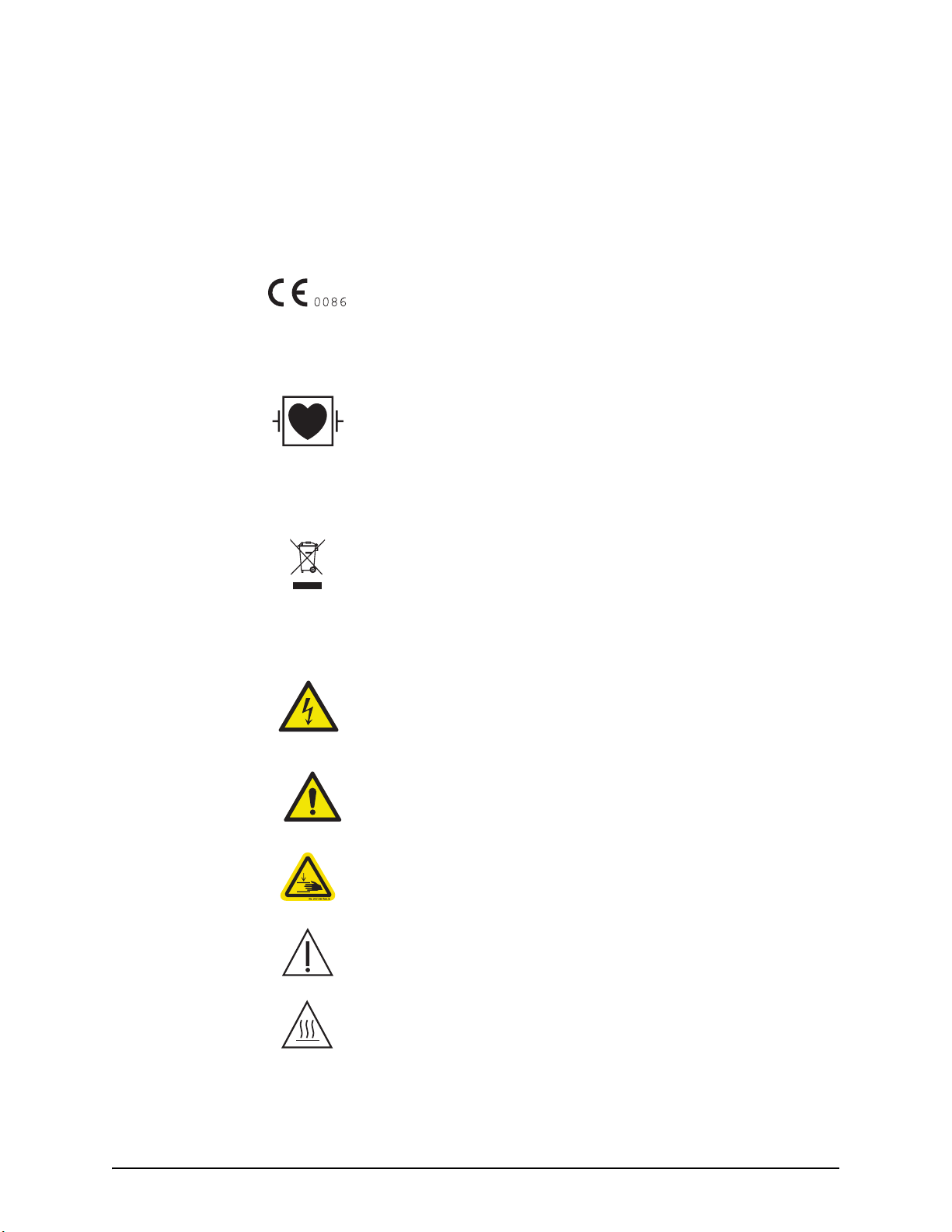
Indicates that this device conforms to requirements of the European Medical
Device Directive 93/42/EEC
3.2 Regulatory Classifications
.
3.3 Warnings
Type Cardial Floating (CF) Defibrillation-Proof applied part as defined by IEC
60417-2.
IPX1 Code that specifies the degree of protection against vertically falling water
drops (IEC 60529).
Indicates separate collection for Electrical and Electronic Equipment per
Directive 2002/96/EC . Refer to the following website for additional information:
http://www.medrad.com/en-us/resources/Pages/WEEE.aspx
Indicates risk of electric shock.
Warning: Refer to warnings and cautions on Instructions for Use packaged in
each carton.
Indicates a pinch or crush hazard.
Attention: Refer to warnings and cautions on Instructions for Use packaged in
each carton.
Indicates hot surface. Item can be hot and should not be touched without taking
care.
3 - 9
Page 18
MEDRAD® Mark 7 Arterion Injection System
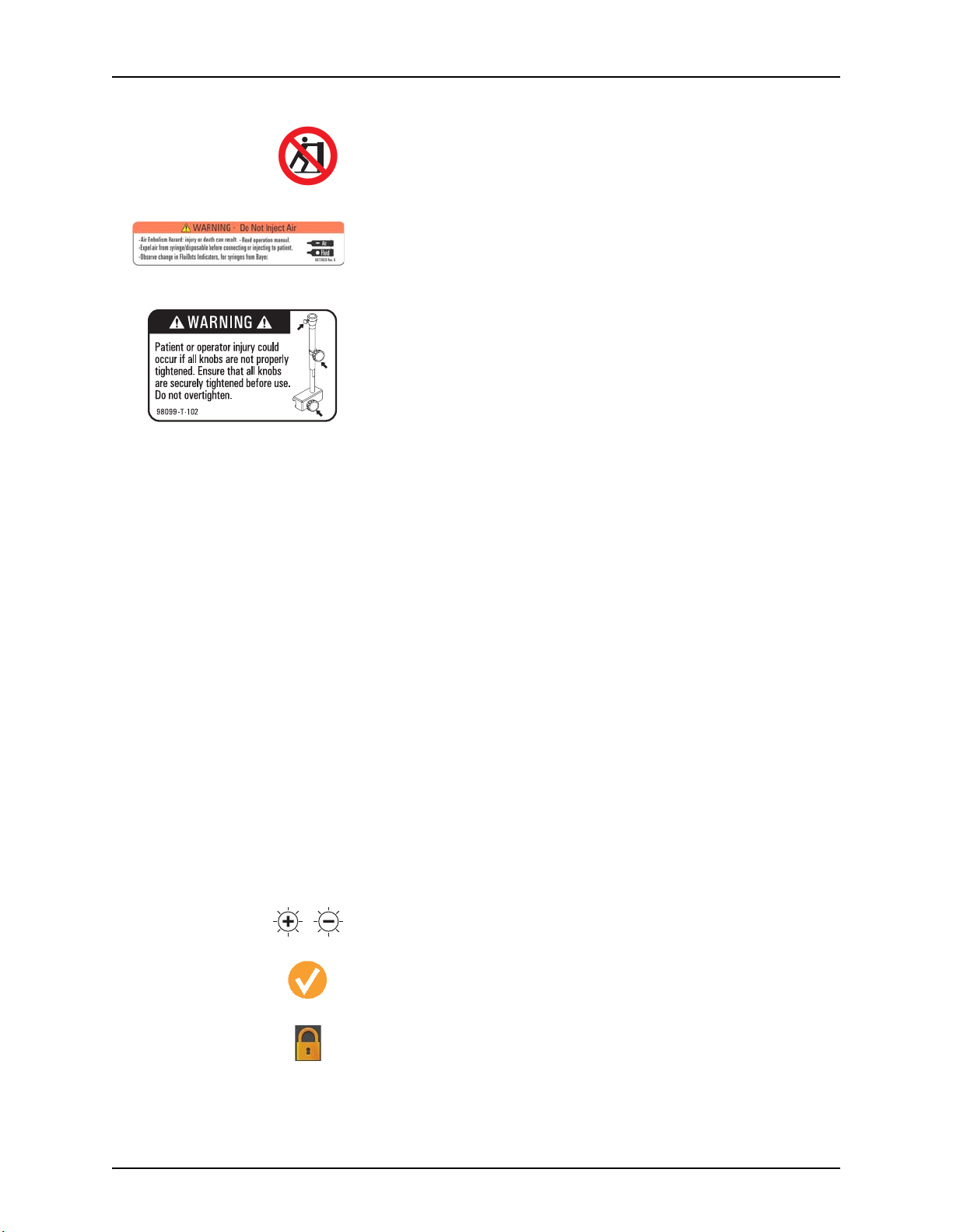
Pushing Prohibited. Do not push at or above this point on the Injector.
Air Warning Label
• Air Embolism Hazard: injury or death can result.
• Read operation manual.
• Expel air from syringe/disposable before connecting or injecting to patient.
• Observe change in FluiDots Indicators, for syringes from Bayer.
Table Mount Warning
Patient or operator injury could occur if all knobs are not properly tightened.
Ensure that all knobs are securely tightened before use. Do not overtighten.
Indicates that the information is a warning. Warnings advise you of
WARNING
circumstances that could result in serious injury or death to the patient or
operator. Read and understand the warnings before operating the injection
system.
Indicates that the information is a caution. Cautions advise you of
CAUTION
NOTICE
NOTE
circumstances that could result in minor or moderate injury to the patient or
operator. Read and understand the cautions before operating the injection
system.
Indicates that the information is a notice. Notices advise you of circumstances
that could result in damage to the device. Read and understand the notices
before operating the injection system.
Indicates that the information that follows is additional important information or
a tip that will help you recover from an error or point you to related information
within the manual.
3.4 Buttons and Icons
The buttons on the Display Control Unit (DCU), Injector Head, and Power Unit allow operators to access
functions on the injector system. The icons used on the DCU, Injector Head, and Power Unit notify
operators about system processes and identify connection ports.
3.4.1 Display Control Unit Buttons and Icons
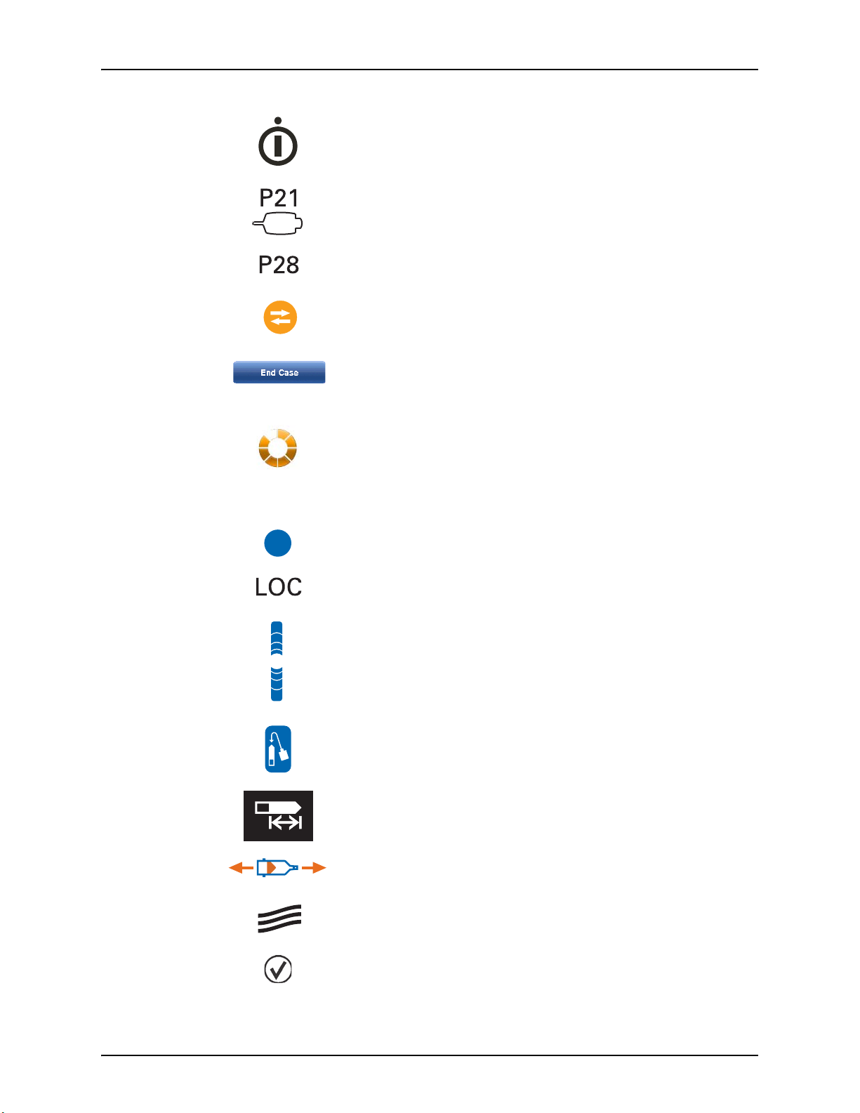
The Display Control Unit brightness controls.
Purged Air Confirmation icon - indicates that the operator has confirmed that all
air has been purged.
3 - 10
Indicates that Display Control Unit is locked because someone is accessing
another Display Control Unit or the Injector Head controls.
Page 19
Symbols and Icons
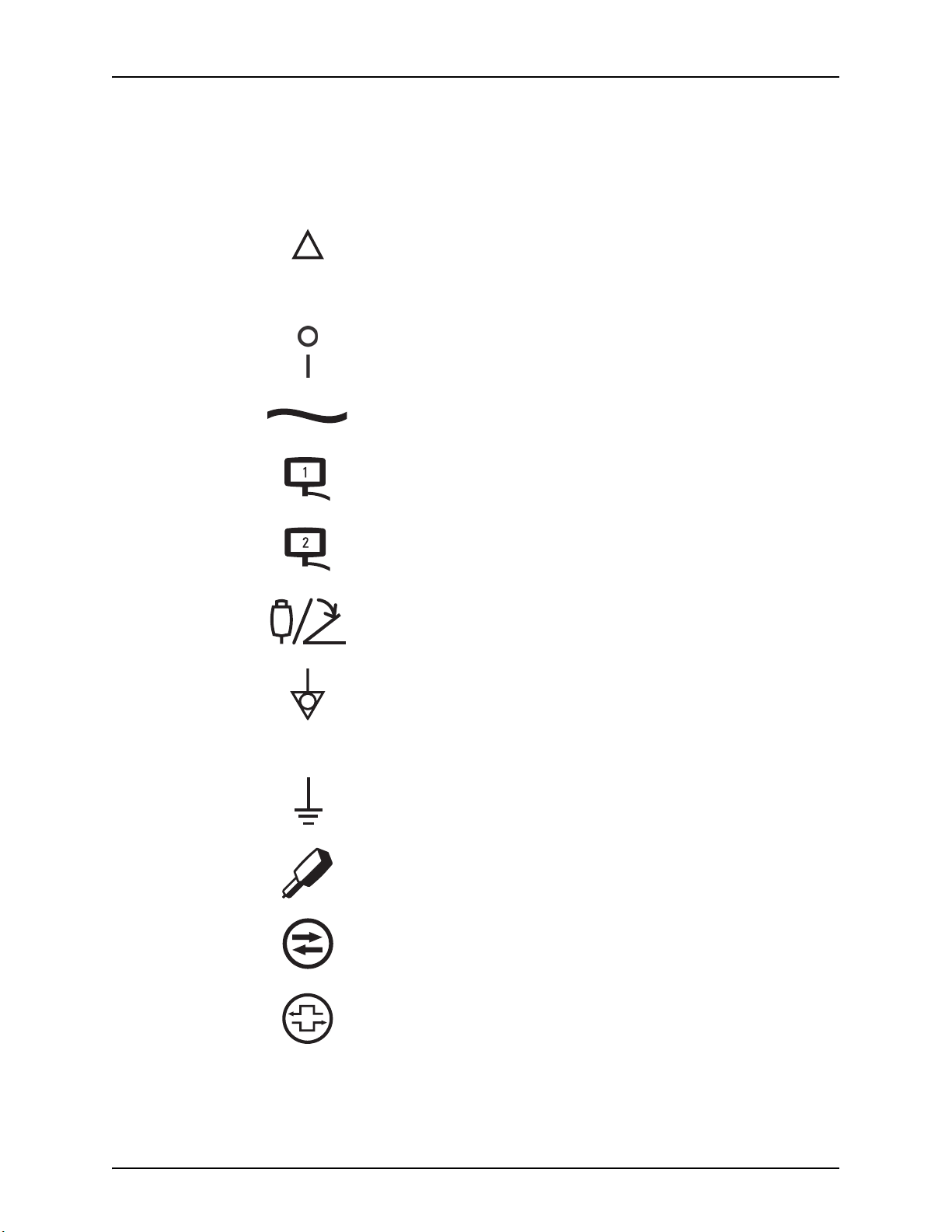
The On/Off Switch.
The hand switch connection location found on the back of the Display Control
Unit.
The Power Unit cable connection location found on the back of the Display
Control Unit.
Indicates that an Imaging System Interface (ISI) is enabled and functioning
properly.
This symbol is also used throughout the manual to indicate ISI specific steps.
Operators use the End Case button to end the injection for a patient case, to
retract the syringe plunger, to clear the Total Contrast number, and to create a
record of the case.
Injection Indicator displays during an injection.
3.4.2 Injector Head Buttons and Icons
The Enable button activates the Fill Strip and Auto-Fill button.
Displays in Volume Remaining LED on the Injector Head when an operator is
accessing the Display Control Unit.
The Fill Strip allows operators to retract and advance the piston from the
Injector Head.
The Auto-Fill button fills the syringe with a user defined contrast volume and at
a user defined speed.
Identifies the Volume Remaining LED.
Identifies rotation direction on the manual knob for manually moving
the piston. Clockwise is forward movement.
The Syringe Heat Maintainer connection location.
Future expansion port.
3 - 11
Page 20
MEDRAD® Mark 7 Arterion Injection System
J31
J32
Hand Controller.
Identifies the Service Port.
Pressure Jacket Syringe Alignment.
3.4.3 Power Unit Icons
Power Unit On/Off switch.
Indicates Alternating Current and identifies the Power Unit power cord
connection.
Identifies a connection for Display Control Unit1. The Power Unit has two
connection points.
Identifies a connection for Display Control Unit2. The Power Unit has two
connection points.
Identifies the hand switch or foot switch connection.
Identifies the Equipotential connection. The Equipotential Connector (EPC) is an
electrically bonded terminal on the injector, used as a connection point between
other medical electrical equipment. The EPCs function is to minimize any
voltage potentials differences between all connected equipment. The EPC is not
designed to be an electrical safety ground.
Identifies the Earth Ground point (this terminal is meant for supplementary
grounding please contact Bayer prior to using this terminal).
Identifies an Injector Head connection. The Power Unit has two connection
points.
Identifies the Imaging System Interface connection.
Identifies the CAN connection.
3 - 12
Page 21

3.5 Packaging
Rx Only
Symbols and Icons
Identifies the service port.
NOTE: Used by Bayer HealthCare Services or Bayer trained
personnel.
Future expansion port.
Future expansion port.
Future expansion port.
Catalog Number
Do not Re-sterilize.
Do not use if package is damaged.
Do Not Reuse
Batch Code
Date of Manufacture/Sterilization
Non-Pyrogenic Fluid Path
Prescription Device - U.S. Federal law restricts this device to sale by or on the
order of a (licensed health care practitioner).
Serial number
Sterilized using Irradiation.
3 - 13
Page 22
MEDRAD® Mark 7 Arterion Injection System
CB
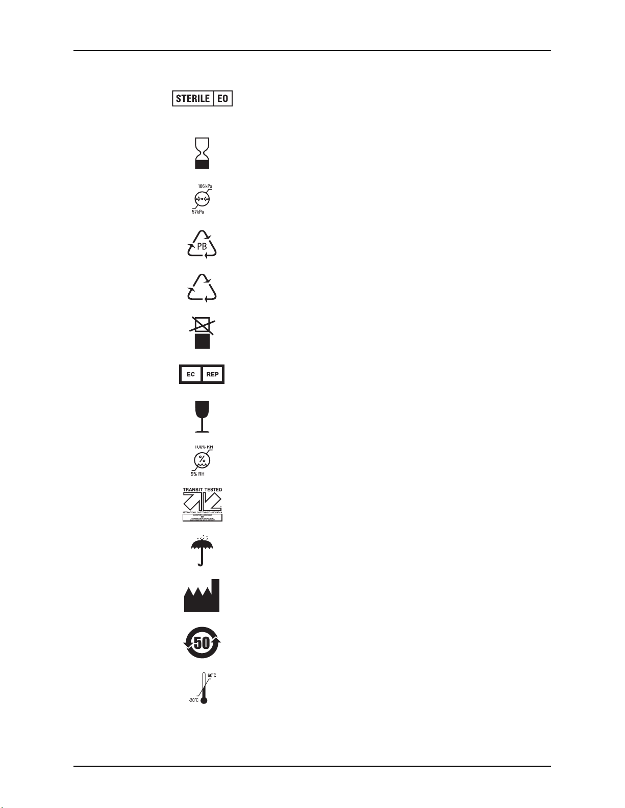
Sterilized with Ethylene Oxide.
Use By
Atmospheric Pressure Limitation
Chinese Recycling symbol for paperboard.
Chinese Recycling symbol for corrugated cardboard.
Do Not Stack
Authorized Representative in the European Community.
Fragile, Handle with care
Humidity limitation
ISTA tested
Keep Dry
Manufacturer
China ROHS - Environmental Protection use Period Mark.
Temperature Limitation
3 - 14
Page 23

This Way Up
Not made with natural rubber latex.
Symbols and Icons
3 - 15
Page 24

MEDRAD® Mark 7 Arterion Injection System
3 - 16
Page 25

4 System Warnings, Precautions, and Notices
4.1 Warnings
Air Embolism Hazard - Serious patient injury or death may result.
• Do not inject air.
• Purge all air from syringe and disposables before connecting or injecting to patient.
• Use only accessories and options provided by Bayer which are designed specifically for
the injection system.
• Inspect system and do not use when signs of damage are evident.
• Verify that the FluiDots indicators are rounded to ensure that fluid is present in the
syringe.
• No modification of equipment is allowed.
Serious patient and/or worker injury or death may result.
• Use of non-Bayer supplied disposables, including administration sets and additions to
administration sets, such as but not limited to bleed back control devices and pressure
transducers may cause patient injury if not properly connected or flushed. These devices
must be compatible with your system. Refer to manufacturer's instructions for proper use
of these devices.
Do not use if sterile package is opened or damaged.
• Patient or operator injury may result if package is opened or damaged, or if damaged
components are used. Visually inspect contents and package before each use.
Cross contamination hazard - Serious patient and/or worker injury or death may result.
• Ensure only syringes from Bayer are used on the system.
• Do not store filled syringes for later use.
• Discard previously filled unused syringes.
• Do not reuse disposables.
• For devices labeled for single use, please note: This product is intended for single
use only. Do not resterilize, reprocess or reuse. The disposable devices have been
designed and validated for single use only. Re-use of the single use disposable
devices pose risks of device failure and risks to the patient. Potential device failure
includes significant component deterioration with extended use, component malfunction,
and system failure. Potential risks to the patient include injury due to device malfunction
or infection as the device has not been validated to be cleaned or re-sterilized.
Procedure Delay Hazard - Serious patient and/or worker injury or death may result.
• Turn off any equipment that could generate an electrostatic discharge during procedure.
Electric Shock Hazard - Serious patient and/ or worker injury or death may result.
• The system should be opened and serviced by Bayer HealthCare Services or Bayer trained
service personnel.
• Use only power cord approved for use on Mark 7 Arterion.
• For U.S. installations, equipment shall only be connected to Hospital Grade or Hospital
Only outlets.
• Disconnect the system from line power before cleaning or attempting to perform any
maintenance or repairs.
• Avoid contact with pins.
• Ensure that connector covers are in place or cables are connected.
• Do not allow injector head to contact patient.
• Equipment must only be connected to supply mains with protective earth.
• Unplug system prior to servicing.
4 - 17
Page 26

MEDRAD® Mark 7 Arterion Injection System
CAUTION
NOTICE
4.2 Cautions
Environmental Contamination Hazard - Minor or moderate patient and/ or worker injury may
result.
• Follow sterile technique specifically, maintain sterility of the syringe tip and plunger,
syringe barrel internal surface, Quick Fill Tube, high pressure connector tubing, catheter,
and Display Control Unit Sheath.
• Properly discard disposables after use, in accordance with hospital hazard waste disposal
procedures.
Mechanical Hazard - Minor or moderate patient and/ or worker injury may result.
• Do not use injector head handle to move injector system.
• Do not use the cabling or syringe to position injector system.
• Do not use system in the presence of flammable or combustible gases or other agents.
• Turn off system power and disconnect patient when system malfunction occurs.
4.3 Notices
Mechanical Hazard - Equipment Damage may result.
• Do not hang items on the Display Control Unit or Wall Mounting Bracket.
• Do not oil the friction plate on the Wall Mount Bracket.
Electro-Mechanical Hazard - Equipment Damage may result.
• Do not use tools to over tighten connections or to assist in the removal of disposables.
• Do not roll pedestal over cables.
• Regular preventive maintenance is recommended to ensure that the system stays
calibrated and functions properly. Refer to maintenance section of this manual or contact
Bayer for additional information.
• Allow two hours for the injector to reach room temperature before use.
• Follow Electrostatic Discharge (ESD) protection practices.
• Disconnect the power cord before removing or replacing PC boards.
• Do not apply voltage to ISI connector.
• Provide only a switch closure if the injector is being started by an external start
connection.
• Do not block Power Unit vents.
• Installation clearance should be a minimum of 3 to 5 inches (8 to 13 cm).
• Before installing the Table Mount, ensure the table rail can withstand a minimum vertical
static load of 18 kg (40 lbs.) Refer to the table manufacturer documentation for weight
load information.
• Do not over tighten Table Mount knob.
• Do not force the Table Mount onto the table rail.
• Loosen Table Mount knob prior to removal of components.
4 - 18
Page 27
5 System Overview
This chapter describes:
• "Injection Protection"
• "Pressure Limiting"
• "System Technical Specifications"
• "High Pressure Connector Tubing Specifications (Non-Twist & Go)"
• "Display Control Unit"
• "Injector Head"
•"Power Unit"
• "Imaging System Interface"
• "Start Switches"
• "Pedestal and Stand Movement"
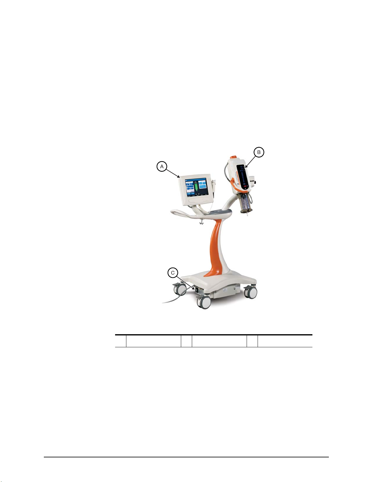
A Display Control Unit B Injector Head C Power Unit
5.1 Injection Protection
The following means are provided to protect against over and under injections:
An on-screen indication of insufficient volume is provided whenever the total volume programmed to
be delivered is greater than the amount of fluid in the syringe.
The system monitors injections to detect over rate or over volume conditions due to system faults. The
delivered volume is also monitored against the total programmed volume for the injection.
Once the system has disarmed a tone will sound and a disarm message displays on the Display Control
Unit screen.
When any fault condition is detected, the injection will stop.
Figure 5 - 1: Mark 7 Arterion Injection System
5 - 19
Page 28

MEDRAD® Mark 7 Arterion Injection System
5.2 Pressure Limiting
The purpose of the programmed pressure limit is to protect the patient, the catheter, and any
disposable device attached to the injector.
As a general rule, set pressure limit no higher than the max pressure rating of the weakest component
in the fluid path (tubing, stopcocks, connectors, catheters, administration sets, etc.).
Max pressure rating examples for an example scenario:
• Tubing - 1200 psi
• Stopcock - 1050 psi
• Catheter - 1200 psi
In this case, set the pressure limit no higher than 1050 psi because anything higher could potentially
cause the component to fail.
Typical factors to consider and how they affect Pressure:
Effects on Pressure
Factors
Fluid Viscosity Low High
Catheter and
Tubing Length
Catheter ID Large Small
Consider the above factors when setting pressure limit to achieve the desired injection flow rate.
Proper pressure limit setting optimizes the angiographic images.
The injector applies the minimum pressure needed to achieve the programmed flow rate. If the
pressure from the injector exceeds the programmed pressure limit, the system cannot achieve the flow
rate and a Sentinel message displays.
Pressure information can be found in the History tab.
5.3 System Technical Specifications
5.3.1 Input Power Requirements
100-240 VAC
50/60 Hz
1000 VA
Decrease
Pressure
Short Long
Increase
Pressure
5 - 20
Page 29

5.3.2 Technical Specifications
Flow Rate:
Volume: 1-150 mL in 1 mL increments
System Overview
Table 5 - 1: System Technical Specs
0.1-45.0 mL/s in 0.1 mL/s
increments (single and phased)
0.1-59.9 mL/m in 0.1 mL/m
increments (single mL/m)
1.0-10.0 mL/s in 0.1mL/s
increments (variable)
Pressure Limit (150 mL
syringe):
Rise Time: 0.0-9.9 seconds in 0.1s increments
Delay Time:
Manual Fill Speed: 1-20 mL/s in 1 mL/s increments
Auto Fill Speed: 1-10 mL/s in 1 mL/s increments
Fill Volume: 1-150 mL in 1 mL increments
Syringe Size: 150 mL
Protocol Memory: 39 Protocols (4 default, 35 storable)
Injection History Memory Approximately 50 injections
100-1200 psi in 1 psi increments
689-8273 kPa in 1 kPa increments
0.0-99.9 seconds in 0.1s
increments
5.4 High Pressure Connector Tubing Specifications (Non-Twist & Go)
The injection system was designed to use the MEDRAD Mark 7 Arterion Syringe and Twist and Go
Syringe. When using the Mark 7 Arterion Syringe, tubing should meet the following specifications to
operate in a safe and effective manner.
• Disposable tubing shall be rated to a minimum of 1200 psi
• Disposable tubing shall have a minimum internal diameter of .070" with a maximum length
of 72".
• Syringe interface luer shall be a standard female luer as defined in:
• ISO 594-1:1986
• EN 20594-1:1993/AC:1996/A1:1997.
• Catheter interface luer shall be a standard male luer as defined in:
• ISO 594-1:1986
• ISO 594-2: 1998
• EN 20594-1:1993/AC:1996/A1:1997.
• Disposable tubing shall be made from a clear polymeric material that allows for proper
visualization of fluid path to ensure all air has been adequately purged with fluid before
connection to a patient.
5 - 21
Page 30
MEDRAD® Mark 7 Arterion Injection System
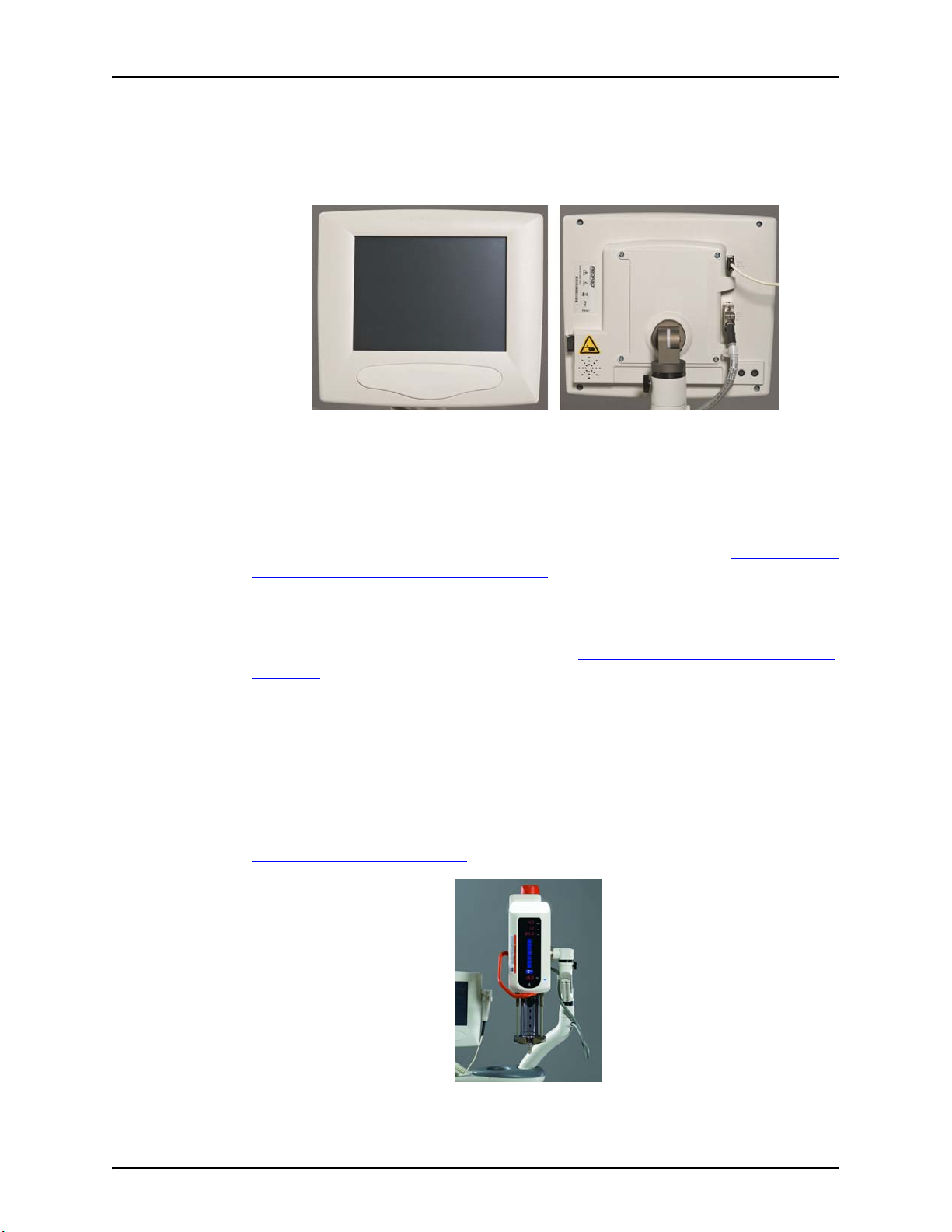
5.5 Display Control Unit
The injection system Display Control Unit consists of a touch screen display. From the Display Control
Unit, an operator can manage protocols, arm and disarm the injector, review injection history, set
options, and view help topics.
The injection system supports the connection of a second Display Control Unit. In a two Display Control
Unit system, both Display Control Units have the same controls and functionality. Depending on
operational situations, only one of the Display Control Units may be active at a time. For example, if an
operator is entering a protocol on a Display Control Unit in the Control room, the system locks-out the
Display Control Unit in the Scan room. See "6.6 - Display Control Unit Lock-outs"
Figure 5 - 2: Display Control Unit
for more information.
For more information about the navigating through Display Control Unit screens, see "Chapter 6 - Using
and Understanding the Display Control Unit Screen".
5.5.1 Display Control Unit Sterile Sheath
If the Display Control Unit will be used in the Sterile Field, a sheath such as the Display Control Unit
Sheath (AVA 500 DCOV) from Bayer should be used. See "16.6.5 - Display Control Unit Sterile Sheath
Installation".
5.6 Injector Head
The Injector Head has a handle that is used to rotate the head. The Injector Head position determines
what functions are active and what values display on the Injector Head. The Injector Head keypad and
Manual Knob can be used to fill and purge a syringe. A drop front allows operators to load syringes
from the front. The Syringe Heat Maintainer clamps onto the Pressure Jacket and connects to the
underside of the Injector Head and is designed to keep pre-warmed contrast in the syringe.
For more information about the Injector Head or the Syringe Heat Maintainer, see "Chapter 7 - Using
and Understanding the Injector Head".
5 - 22
Figure 5 - 3: Injector Head
Page 31

5.7 Power Unit
The injection system Power Unit supplies power to the Injector Head and the Display Control Unit. As
the main communications hub, the Power Unit provides system communications to all connected
components. A green light illuminates when the Power Unit is on.
The front plate on the Power Unit contains a serviceable air filter. For cleaning instructions, see
"Chapter 15 - Cleaning and Maintenance"
5.8 Imaging System Interface
The Imaging System Interface (ISI) allows the injection system to interface with an imaging system to
provide synchronization of an injection and an X-ray exposure. To use ISI on the injection system,
configure the system from the Display Control Unit Options tab. See "Chapter 6 - Using and
Understanding the Display Control Unit Screen". For more information on how ISI interacts with the
injection system, see "11.3.5 - Performing an Injection with Imaging System Interface (ISI)"
5.9 MEDRAD® VFlow
MEDRAD VFlow (VFlow) enables the use of Variable Flow Rate injections. In the Variable Flow Rate
injection mode, the injector automatically re-arms after each injection. A Variable Flow Rate injection
can be initiated by the Hand Controller and ranges from 1 - 10 mL/sec in increments of 0.1 mL/sec.
Variable Flow Rate is intended for use in those procedures where low volumes are injected and
Variable Flow Rate control is desired. The system has an option for receiving audible feedback when
using the Hand Controller. The feedback indicates the flow rate.
See "6.4 - Options Tab"
System Overview
.
.
for instructions on how to enable VFlow.
5.10 Start Switches
The injection system can be used with a hand switch, foot switch and/or hand controller. The switches
allow the operator to initiate an injection.
Single mL/s Phased Variable Flow Rate Single mL/m
Hand switch X X X
Foot switch X X X
Hand ControllerXXXX
5.10.1 Hand Switch and Foot Switch
For installation instructions, see "16.6.3 - Hand Switch and Foot Switch Installation"
Figure 5 - 4: Hand Switch and Foot Switch
.
5 - 23
Page 32

MEDRAD® Mark 7 Arterion Injection System
A
B
5.10.2 MEDRAD VFlow Hand Controller
The VFlow Hand Controller is a sterile device intended for single patient use.
The Hand Controller works in two different modes, Variable Flow Rate and Fixed Flow Rate. When in
the Variable Flow Rate injection mode, the flow rate increases incrementally as the Hand Controller
plunger (A) is depressed, and decreases as the Hand Controller is released. In the Fixed Flow Rate
injection mode, the Hand Controller acts as a start switch, and release of the device ceases all flow.
The Hand Controller button (B) is non-functional and will beep from the Injector head and DCU when
depressed.
Figure 5 - 5: Hand Controller
NOTE: The hand controller is required to perform Variable Flow Rate injections. For
installation instructions, see"10.5 - Installing the MEDRAD® VFlow Hand
Controller".
5 - 24
Page 33

5.11 Pedestal and Stand Movement
5.11.1 Pedestal System
Place pedestal system components into the approximate positions shown in Figure 5 - 6 prior to
moving the system. When necessary, lift pedestal by using the handle to move over obstacles.
System Overview
Figure 5 - 6: Approximate Component Positions for System Movement
5 - 25
Page 34

MEDRAD® Mark 7 Arterion Injection System
5.11.2 Head Stand (KMA 320 RT) and Adjustable Height Stand (KMA 330)
Place hands in the positions shown in Figure 5 - 7 to move an injector Head mounted on a Head Stand
and Adjustable Height Stand over obstacles.
5 - 26
Figure 5 - 7: Approximate Hand Positions to Move Head Stand and Adjustable Height Stand Over
Obstruction
Page 35

5.11.3 Mark 7 Arterion Stand Mounting Kit Configuration
Place the Mark 7 Arterion Stand Mounting Kit components into the approximate positions and place
hands in the positions shown in Figure 5 - 8 prior to moving the system.
System Overview
Figure 5 - 8: Approximate Hand Positions to Move Stand Mounting Kit Configuration over
Obstruction
5 - 27
Page 36

MEDRAD® Mark 7 Arterion Injection System
5 - 28
Page 37

6 Using and Understanding the Display Control Unit Screen
The Display Control Unit touch screen has five tabs from which an operator can manage protocols, arm
and disarm the injector, review injection history, set options, and view help topics.
6.1 Home Tab
NOTE: An operator will be locked-out from a Display Control Unit if another operator is
performing functions on the Injector Head or another Display Control Unit
connected to the same system.
The chapter discusses:
• "Home Tab"
• "Protocols Tab"
•"History Tab"
•"Options Tab"
•"Help Tab"
• "Display Control Unit Lock-outs"
• "Performing Touch Screen Calibration"
Operators can set protocols, select the Single or Phased protocol, or arm the injector on the Home tab.
This tab has a Programmed window (A), Actuals window (B), and Sentinel window (C). Each of these
windows is discussed below.
6.1.1 Programmed Window
The Programmed window displays the protocol parameters for an injection including Flow Rate,
Volume, Pressure, Rise time (Rise Time is not listed for Variable Flow Rate or mL/m protocols), and
Delay (Delay is not listed for phased and Variable Flow Rate or mL/m protocols).
Operators can set Single mL/s and mL/m, Phased, and Variable Flow Rate protocols from the
Programmed window. For more information, see "9.1 - Set Injection Parameters from the Home Tab"
Figure 6 - 1: Home Tab
.
6 - 29
Page 38

MEDRAD® Mark 7 Arterion Injection System
6.1.2 Actuals Window
The Actuals window displays Peak (maximum Flow Rate achieved), Delivered (actual total volume
delivered), Total Contrast (total volume delivered for the current case), and the End Case button. An
operator presses the End Case button after completing a patient procedure and before removing the
disposables to retract the syringe plunger. This button also zeroes the Total Contrast and creates a new
case entry on the History tab. For more information on cases, see "6.3 - History Tab"
6.1.3 Sentinel Window
The Sentinel window displays system messages, such as “Rotate head down to arm”. The Sentinel
window also displays the status of the last injection.
The Sentinel window message flashes momentarily when the system cannot arm.
A list of messages is available in Chapter 13 “System Messages.”
6.2 Protocols Tab
Operators can store new protocols, recall stored protocols, and edit existing protocols on the Protocols
tab. For information on how to manage protocols from the Protocols tab, see "9.2 - Manage Protocols
from the Protocols Tab".
NOTE:To set protocol parameters from the Home tab, see "9.1 - Set Injection Parameters
from the Home Tab".
.
6.3 History Tab
6.4 Options Tab
The History tab shows a list of recent injections with date and time of the injection and the
programmed parameters and actuals. Injections are grouped by case. Cases are reset when an
operator selects the End Case button from the Home tab.
For example, an operator may want to group all of the injections for one patient together. The operator
performs all of the injections for a patient. The operator then selects the End Case button after the last
injection has completed. The system groups all of the injections for that patient together. This group of
injections can be retrieved from the History tab.
Operators can modify system settings from the Options tab. A green LED displays beside the current
setting for each option. When an operator changes a setting, the system adds an asterisk next to the
option name to identify unconfirmed setting changes. To enable the new settings, select one of the
other tabs, such as Home. A popup displays requesting confirmation for the new value. Select Ye s to
confirm the setting. Select No to go to the selected tab without saving the changes; the system reverts
to the previous settings.
Table 6 - 1: Options
Option Description
Language Sets the Display Control Unit display language.
Flow Rate Select mL/m or mL/s.
6 - 30
Fill Volume
Fill Speed
Determines the volume of contrast drawn into the syringe when an
operator presses the Auto-Fill button on the Injector Head.
Determines the speed at which the injector draws contrast into the
syringe when an operator presses the Auto-Fill button on the Injector
Head.
Page 39

Using and Understanding the Display Control Unit Screen
Option Description
Table 6 - 1: Options
ISI
Auto Retract
Phased Enables or disables Phased protocols.
Date/Time Sets the system date and time and the calibration date.
Pressure Units Sets the pressure measurement to PSI or kPa. PSI is set by default.
Head Audio Volume Sets the audio volume level for the Injector Head.
DCU Audio Volume Sets the audio volume level for the Display Control Unit.
Upgrade
MEDRAD
Audio Feedback
15 mL Purge
®
VFlow
Enables or disables Imaging System Interface (Single mL/s protocols
only).
Enables or disables the piston auto retract feature. See "7.3.1 - Piston
Auto Retract" for more information.
Used by Bayer HealthCare Services or Bayer trained personnel to
activate features.
Enables Variable Flow Rate injections when this feature is activated
from Upgrade. Contact Bayer to enable this feature.
When VFlow
Controller plunger is depressed.
With this feature enabled, the system provides a choice between two
configurations (ON or OFF) of the 15 mL Purge Option. Contact Bayer
to enable this feature.
is enabled, the system provides a sound when the Hand
6.4.1 Modify Options
To modify an option:
6.5 Help Tab
The Help tab provides a list of help topics.
To view a help topic
1. Select the Options tab. A list of options displays. For an explanation of the options, see
Tabl e 6 - 1.
2. Select an option. A center panel displays with setting choices or a numeric keypad based on
the option.
3. Make the appropriate changes.
4. Select another tab to save the changes. A popup displays requiring confirmation to save the
changes or revert back to previous settings. Select Yes to save changes. Select No to revert
back to previous settings.
1. Select the Help tab.
2. Select the topic name.
6 - 31
Page 40

MEDRAD® Mark 7 Arterion Injection System
6.6 Display Control Unit Lock-outs
The Display Control Unit will be locked-out while an operator is interacting with the Injector Head
controls, or while an operator is accessing another Display Control Unit in a dual Display Control Unit
system.
The inactive Display Control Unit remains in lock-out until (A):
1. the operator finishes accessing the active Display Control Unit, and active Display Control
Unit displays the Home tab,
2. or, an operator has accessed the active Display Control Unit and doesn’t do anything for a
minute,
3. or, an operator has not interacted with the Injector Head controls for a period of several
seconds.
Figure 6 - 2: Display Control Unit Locked Out
6.7 Performing Touch Screen Calibration
Calibrate the Display Control Unit if the touch screen does not respond appropriately when pressing
buttons on the screen. To calibrate at the Safety Screen, simultaneously press the Brightness Up and
Brightness Down buttons on the back of the Display Control Unit. Follow the on-screen instructions
that display.
NOTE: Touch the center of the calibration targets to ensure proper touch screen
calibration.
Figure 6 - 3: Touch Screen Calibration
6 - 32
Page 41

7 Using and Understanding the Injector Head
This chapter describes:
• "Injector Head Components"
• "Injector Head Position"
• "Syringe Interface"
• "Pressure Jacket"
• "Injector Head Displays"
• "Injector Head Controls"
• "Armed Light"
• "Manual Knob"
• "Syringe Heat Maintainer"
• "Injector Head Lock-outs"
7.1 Injector Head Components
Figure 7 - 1: Injector Head
ADrop Front B
C Injector Head Handle. D
Injector Head Controls - See "7.6 - Injec-
E
tor Head Controls"
G Manual Knob - See "7.8 - Manual Knob"
F Armed Light - See "7.7 - Armed Light"
Pressure Jacket - See"7.4 - Pressure
Jacket"
Injector Head Displays - See "7.5 - Injec-
tor Head Displays"
7 - 33
Page 42

MEDRAD® Mark 7 Arterion Injection System
Z
X
Y
7.2 Injector Head Position
The Mark 7 Arterion Injector Head contains a sensor that monitors the head’s position: Purge (upright)
(X), Intermediate (Y), or Inject (downward) (Z). The head position determines how the data displays and
the available functions. Use the handle and the back of the Injector Head (but not the Manual Knob) to
rotate the head into position.
Functions
Fill Enabled Enabled Enabled
Inject Disabled Disabled Enabled
7.3 Syringe Interface
The syringe interface supports a single 150 mL syringe. Operators can attach a syringe to the head
from the front of the injector (front loading). The syringe locks into place when the drop front is fully
7 - 34
Figure 7 - 2: Injector Head Position
Table 7 - 1: Injector Head Position and Functionality
Injector Head Position
Purge (X) Intermediate (Y) Inject (Z)
Page 43

closed. An operator can remove the syringe from the piston rod at any point within the normal travel of
the piston by rotating the syringe 1/4 turn clockwise, while the Injector Head is powered on or off, and
without removing the disposable set from the syringe.
7.3.1 Piston Auto Retract
The Mark 7 Arterion Injection System has an auto retract option that automatically retracts the piston
when the Injector Head is in the Purge position. Below are the two scenarios that describe how this
feature functions when the Injector Head is in the Purge Position or in the Intermediate and Inject
Positions (see "7.2 - Injector Head Position"
• Purge position - The operator lowers the drop front and removes the syringe. The Injector
• Intermediate and Inject Positions - The operator lowers the drop front, removes the
7.4 Pressure Jacket
The Mark 7 Arterion has a Pressure Jacket designed to hold the syringe in place and help to maintain
syringe integrity during use.
Using and Understanding the Injector Head
for a description of the positions).
Head beeps three times and auto-retracts to the syringe ready position.
syringe, and rotates the Injector Head into the Purge (upright) position. The injector Head
beeps three times and auto-retracts to the syringe ready position.
NOTE: Press any key on the Injector Head to halt the auto retract.
NOTE: Enable the auto retract feature from the Options tab. See "6.4 - Options Tab"
more information.
for
The Pressure Jacket is manufactured from high impact resistant material; however, sharp impacts
such as from dropping, may cause small barely visible cracks to form, which may propagate during
subsequent pressure cycles.
7.4.1 Pressure Jacket Storage
When not in use, the Pressure Jacket should remain securely attached to the Injector Head.
Alternatively, the Pressure Jacket may be wrapped in a cloth and stored where it will not be hit or
dropped.
After each procedure, check the Pressure Jacket for contrast build up. For Pressure Jacket cleaning
and maintenance, see "Chapter 15 - Cleaning and Maintenance"
Figure 7 - 3: Pressure Jacket
.
7 - 35
Page 44

MEDRAD® Mark 7 Arterion Injection System
E
C
A
B D
H
F
G
I
7.5 Injector Head Displays
The Injector Head has two display areas. One area shows the programmed parameters for flow rate,
volume, and pressure limit. The other area shows the volume remaining in the syringe.
Figure 7 - 4: Injector Head Display
A Flow Rate B Volume
C Pressure Limit D Volume Remaining
E Volume Remaining Icon F Enable Button
G Enable Indicator H Fill Strip
I Auto-Fill Button
7.5.1 Flow Rate (A)
The flow rate displays the programmed rate. For Phased protocols, the Injector Head displays the
values of the current phase. The flow rate displays in per second or per minute mode based on the
protocol parameters. Operators can change the flow rate mode using the Options tab. See "6.4 -
Options Tab" for more information.
7.5.2 Volume (B)
The volume displays the programmed volume in milliliters. For Phased protocols, the Injector Head
displays the values of the current phase.
7.5.3 Pressure Limit (C)
The pressure limit indicates the maximum pressure that the system can use to inject contrast for the
programmed protocol. The limit displays in either psi or kPa. To understand more about pressure
limiting, see "5.2 - Pressure Limiting"
or the Display Control Unit Help Tab.
7.5.4 Volume Remaining (D)
The volume remaining indicates the amount of contrast currently in the syringe.
7 - 36
Page 45

7.6 Injector Head Controls
The Injector Head Controls on the injection head display contain the Enable button, Enable Indicator,
Fill Strip, and Auto-Fill button.
7.6.1 Enable Button (F)
The Enable button activates the Fill Strip and Auto-Fill button. After pressing the Enable button, the
Enable Indicator (G) illuminates and the Fill Strip and Auto-Fill button stay active while in use or for
five seconds of inactivity.
7.6.2 Fill Strip (H)
The Fill Strip allow operators to advance and retract the piston on the Injector Head. After pressing the
Enable button, press the forward arrows (closest to syringe) to advance the piston, or press the
reverse arrows (farthest from syringe) to retract the piston. The piston speed increases progressively
as an operator presses the arrows farther away from the Enable button.
7.6.3 Auto-Fill Button (I)
The Auto-Fill button fills the syringe with a user-defined contrast volume and at a user defined speed.
After pressing the Enable button, press the Auto-Fill button. Configure the volume and speed from the
Options tab. See "6.4 - Options Tab"
Using and Understanding the Injector Head
.
7.6.3.1 Auto-Fill Button with 15 mL Purge Configuration Options
Table 7 - 2: 15 mL Purge Configuration Options
15 mL Purge ON 15 mL Purge OFF
Auto-Fill available for use in any Injector position.
Auto-Fill only available for use in the Injector’s
upright position.
7.7 Armed Light
The Armed Light (J) remains illuminated when the system is armed. The light flashes once every
second when injecting
Figure 7 - 5: Armed Light
7 - 37
Page 46

MEDRAD® Mark 7 Arterion Injection System
7.8 Manual Knob
Use the Manual Knob (K) to manually advance or retract the piston. Turn the knob clockwise to
advance the piston and counterclockwise to retract the piston.
7.9 Syringe Heat Maintainer
The Syringe Heat Maintainer clamps onto the Pressure Jacket and connects to the underside of the
Injector Head and is designed to keep pre-warmed contrast in the syringe. For information on installing
the Syringe Heat Maintainer, see "16.6.1 - Syringe Heat Maintainer Installation"
7.10 Injector Head Lock-outs
The Injector Head will be locked-out while an operator is accessing a Display Control Unit. LOC displays
in the volume remaining.
The Injector Head remains in lock-out until:
1. An operator finishes accessing the active Display Control Unit, and active Display Control Unit
displays the Home tab,
2. Or, an operator has accessed the active Display Control Unit and doesn’t do anything for a
minute.
Figure 7 - 6: Manual Knob
.
7 - 38
Page 47

8 Power Up and Shutdown the Injector
CAUTION
CAUTION
This chapter describes:
• "Powering up the System"
• "Shutdown"
8.1 Powering up the System
Electric Shock Hazard - Minor or moderate patient and/ or worker injury may result.
• Verify that the voltage and frequency marked on the serial tag on the Power Unit matches
the voltage and frequency of the electrical outlet.
• Do not use extension cord or power adaptor with the system.
1. Press the Power Switch on the Power Unit.
2. Open the power switch cover on the Display Control Unit, and press the Power Switch. A
splash screen and then a safety screen displays.
3. Close the power switch cover.
4. Read the warnings and press Continue. The Home tab displays.
8.2 Shutdown
1. Open the power switch cover on the Display Control Unit, and press the Power Switch.
2. Close the power switch cover.
3. Press the Power Switch on the Power Unit.
8.3 Emergency Shutdown
Mechanical Hazard - Minor or moderate patient and/ or worker injury may result.
• Turn off system power and disconnect patient when system malfunction occurs.
In the event of an emergency such as a fire, explosion, or electrical shock, press the Power Switch at
either the Display Control Unit or Power Unit, or disconnect the power cord from the wall outlet to shut
down the system.
8 - 39
Page 48

MEDRAD® Mark 7 Arterion Injection System
8 - 40
Page 49

9 Setting and Managing Protocols
Over Volume Hazard - Serious patient injury or death may result.
• Do not program a protocol outside of the clinically accepted volume range.
• Ensure that the correct volume is programmed in the protocol for the target anatomy.
Vessel Dissection Hazard - Serious patient injury or death may result.
• Do not program a protocol outside of the clinically accepted flow rate range.
• Ensure that the correct flow rate is programmed in the protocol for the target anatomy.
• Do not program a protocol outside of the clinically accepted pressure limit.
• Ensure that the correct pressure limit is programmed in the protocol for the target
anatomy.
Foreign Body Embolism Hazard - Serious patient injury or death may result.
• Do not program a pressure greater than the lowest rated disposable’s pressure rating.
Bloodborne contamination hazard - Serious patient and/or worker injury or death may
result.
• Do not program a pressure greater than the lowest rated disposable’s pressure rating.
This chapter discusses how to:
• "Set Injection Parameters from the Home Tab"
• "Manage Protocols from the Protocols Tab"
Setting and Managing Protocols
9.1 Set Injection Parameters from the Home Tab
NOTE: Refer to syringe and disposable packaging to confirm lowest pressure rating prior
to programing an injection.
9.1.1 Set Injection Parameters on Home Tab - Single
A Single protocol injects a set Volume of contrast at one flow rate, pressure, rise time, and delay time
(if using ISI).
NOTE: Delay and rise time are not available for mL/m protocols.
1. Select the Single tab (A).
Figure 9 - 1: Set Single Protocol
9 - 41
Page 50

MEDRAD® Mark 7 Arterion Injection System
NOTE: The displayed values are based on the last used protocol or the default values.
2. Select the box corresponding to a parameter to change it.
3. Use the numeric keypad to enter the protocol parameter.
4. Commit the value by selecting Enter or another parameter.
5. Select Delay. A numeric keypad displays with X-Ray and Inject buttons. a. Enter the delay time. Setting delay time to zero is equivalent to having no delay.
b. Select X-Ray or Inject.
c. Select Enter to commit the value.
NOTE: A programmed delay parameter only functions when using ISI.
6. Repeat steps 2-4 to change additional parameters.
9.1.2 Set Injection Parameters on Home Tab - Phased
Phased Protocols have up to four different sets of flow rates and volumes for single continuous
injection. Operators can enter up to four phases per protocol. The pressure limit remains consistent for
each phase.
NOTE: The initial rise time is dependent on the value the operator enters. The intra-phase
rise time is fixed.
NOTE: If the Phased option is not visible, go to the Display Control Unit Options tab to
enable Phased injections. See "6.4 - Options Tab"
NOTE: ISI does not function with Phased protocols.
1. Select the Phased tab (A).
.
9 - 42
Figure 9 - 2: Set Phased Protocol
From the Programmed window, operators can modify protocol parameters and existing
phases, add phases, or delete phases.
• To modify an existing phase, go to step 2.
• To modify the pressure limit, rise time, or delay, go to step 3.
• To add a phase, go to step 4.
• To delete a phase, go to step 5.
2. To modify values for an existing Phase, select the Flow Rate or Volume to the right of the index number (B) for that phase.
a. Select either Flow Rate or Volume.
b. Use the numeric keypad to enter the protocol parameter.
c. Commit the value by selecting Enter or another parameter.
Page 51

Setting and Managing Protocols
d. Repeat this step to change additional parameters.
NOTE: When editing a phase, an operator cannot delete a phase.
3. Select Pressure Limit or Rise Time to change that parameter. a. Use the numeric keypad to enter the protocol parameter.
b. Commit the value by selecting Enter or another parameter.
4. To add a phase, select the index number (C) for the phase directly below the last entered
phase. A new phase is added with flow rate and volume both equal to “1”.
a. In the new phase, select either Flow Rate or Volume.
b. Use the numeric keypad to enter the protocol parameter.
c. Commit the value by selecting Enter or another parameter.
d. Repeat this step to add additional parameters.
5. To delete a phase, select the index number for the phase. If a lower numbered phase is
deleted, the higher number remaining phases are renumbered. For example, in a three phase
protocol, if Phase 1 is deleted, Phases 2 and 3 become Phases 1 and 2.
NOTE: If values for only one phase exist, that phase cannot be deleted.
9.1.3 Set Injection Parameters on Home Tab - Variable Flow Rate
A Variable Flow Rate protocol injects a set Volume of contrast at a Flow Rate determined by the Hand
Controller. As an operator depresses the Hand Controller plunger, the system increases the Flow Rate
until it reaches the maximum Flow Rate set by the operator.
NOTE: If the Variable Flow Rate option is not visible, go to the Display Control Unit Options
NOTE: ISI does not function with Variable Flow Rate protocols.
1. Select the Variable tab (A).
NOTE: The displayed values are based on the last used protocol or the default values.
2. Select the box corresponding to a parameter to change it.
3. Use the numeric keypad to enter the protocol parameter.
4. Commit the value by selecting Enter or another parameter.
5. Repeat steps 2-4 to change additional parameters.
tab to enable MEDRAD VFlow. See "6.4 - Options Tab"
Figure 9 - 3: Set Variable Flow Rate Protocol
.
9 - 43
Page 52

MEDRAD® Mark 7 Arterion Injection System
9.2 Manage Protocols from the Protocols Tab
NOTE: To store, view, or edit mL/m, Phased, or Variable Flow Rate protocols, enable that
protocol type from the Display Control Unit Options tab. See "6.4 - Options Tab"
the mL/m option is enabled, only mL/m protocols display.
9.2.1 Create Protocols
The injection system can store up to 40 protocols. The number of protocols stored on the system
displays in the upper right corner of the Protocols tab. Each protocol stores the volume, flow rate,
pressure limit, rise time, and delay.
NOTE: Refer to syringe and disposable packaging to confirm lowest pressure rating prior
to programing and injection.
9.2.1.1 Create a New Single mL/s or mL/m Protocol on the Protocols tab
A Single protocol consists of a single volume, flow rate, pressure limit, rise time, and delay.
NOTE: Delay and rise time are not available for mL/m protocols.
1. Select the Protocols tab.
. If
9 - 44
Figure 9 - 4: Protocols Tab - Single Protocols
2. Select the Type (B) button until Single is highlighted. A list of Single protocols displays.
3. Select the blank blue button (A).
NOTE: If a blank button is not visible, scroll through the list of protocols until one displays.
If a blank button is not available or 0 Available displays in the upper right corner,
the system cannot store any more protocols. Delete a protocol to add a new one.
4. Enter the protocol name.
5. Select a parameter and enter the values for the selected parameter.
NOTE: If an operator tries to commit a value outside of the acceptable range, an audible
beep sounds and the parameter range blinks in the keypad.
6. Select a different parameter to commit the values.
7. To enter a delay, select Delay. a. Enter the delay time. Setting the delay time to zero is equivalent to having no delay.
b. Select X-Ray or Inject.
NOTE: A programmed delay parameter only functions when using ISI.
8. Select Save.
Page 53

Setting and Managing Protocols
9.2.1.2 Create a New Phased mL/s Protocol on the Protocols tab
Phased protocols consist of multiple phases of Volumes and flow rates with a single pressure limit and
rise time.
NOTE: ISI does not function with Phased protocols.
1. Select the Protocols tab.
Figure 9 - 5: Protocols Tab - Phased Protocols
2. Select the Type (B) button until Phased is highlighted. A list of Phased protocols displays.
NOTE: If the Phased button on the Protocols tab is not displayed, go to the Options tab to
enable Phased Protocol. See "6.4 - Options Tab"
3. Select the blank blue button (A).
NOTE: If a blank button is not visible, scroll through the list of protocols until one displays.
If a blank button is not available or “0 Available” displays in the upper right corner,
the system cannot store any more protocols. Delete a protocol to add a new one.
4. Enter the protocol name.
5. To enter phases: a. Select Volume or Flow Rate. Phase 1 displays with default values.
b. Select Volume or Flow Rate for Phase 1 to modify the settings.
for more information.
9 - 45
Page 54

MEDRAD® Mark 7 Arterion Injection System
c. To enter a new phase, select an empty index number (C). A new phase is added with
default values for flow rate and volume.
d. Enter the phase values, as needed
Figure 9 - 6: Index Number
NOTE: The currently selected values update in the top row parameters. The value in the
Phased Selection pane does not update until the value is committed.
e. To commit the values, select a different parameter.
f. Repeat this step for each phase to be added.
6. Select Pressure or Rise Time. a. Enter the parameter values.
b. To commit the values, select a different parameter.
c. Repeat this step for each parameter to be set.
NOTE: The operator enters the initial rise time. The intra-phase rise time is fixed.
7. Select Save.
9.2.1.3 Create a New Variable Flow Rate Protocol on the Protocols tab
A Variable Flow Rate protocol injects a set Volume of contrast at a Flow Rate determined by the Hand
Controller. As an operator depresses the Hand Controller plunger, the system increases the flow rate
until it reaches the maximum Flow Rate set by the operator.
NOTE: If the Variable Flow Rate option is not visible, go to the Display Control Unit Options
tab to enable MEDRAD VFlow. See "6.4 - Options Tab"
NOTE: ISI does not function with Variable Flow Rate protocols.
1. Select the Protocols tab.
2. Select the Type button until Variable is highlighted. A list of Variable Flow Rate protocols
displays.
.
9 - 46
Page 55

Setting and Managing Protocols
Figure 9 - 7: Protocols Tab - Variable Flow Rate Protocols
3. Select the blank blue button (A).
NOTE: If a blank button is not visible, scroll through the list of protocols until one displays.
If a blank button is not available or 0 Available displays in the upper right corner,
the system cannot store any more protocols. Delete a protocol to add a new one.
4. Enter the protocol name.
5. Select a parameter and enter the values for the selected parameter.
NOTE: If an operator tries to commit a value outside of the acceptable range, an audible
6. Select a different parameter to commit the values.
7. Select Save.
9.2.2 Recall a Stored Protocol
An operator can recall a protocol for use, view the parameters, edit the parameters, or delete the
protocol.
1. Select the Protocols tab. The currently selected protocol (A) on the Home tab displays at the top of the list.
beep sounds and the parameter range blinks in the keypad.
Figure 9 - 8: Active Protocol
9 - 47
Page 56

MEDRAD® Mark 7 Arterion Injection System
2. Select the Type button to display the type of protocol to be recalled.
3. Select the Sort button to sort the protocols. The options are:
• Sort A-Z
•Sort Z-A
• Most Frequently Used
• Most Recently Used
4. Press the up or down arrow to locate the protocol.
5. Select the protocol name to load the protocol for use. The system returns to the Home tab
with the selected protocol parameters displayed.
9.2.3 Edit an Existing Protocol
9.2.3.1 Edit Single ml/s or ml/m or Variable Flow Rate Protocol
1. If in the Armed state, select Disarm.
2. Select the Protocols tab.
3. Select the Type button to display the protocol type to be edited.
NOTE: If the Variable Flow Rate type is not displayed, go to the Options tab to enable
MEDRAD
4. Navigate to the desired protocol.
5. Select the Edit button.
6. Select a parameter to change it.
7. Use the keypad to enter the new values.
8. Commit the value by selecting Enter or another parameter.
9.2.3.2 Edit Phased mL/s Protocol
1. If in the Armed state, select Disarm.
2. Select the Protocols tab.
3. Select the Type button to display the protocol type to be edited.
NOTE: If the Phased type is not displayed, go to the Options tab to enable Phased
Protocol. See "6.4 - Options Tab"
4. Navigate to the desired protocol.
5. Select the Edit button.
6. To edit phases: a. Select a parameter. The phased protocol displays.
b. Locate the phase to be edited.
c. Select a parameter, such as Volume or Flow Rate.
d. Use the keypad (A) to enter the values for the selected parameter.
®
VFlow. See "6.4 - Options Tab".
.
9 - 48
Page 57

Setting and Managing Protocols
Figure 9 - 9: Edit Phased Protocols
e. To commit the values, select a different parameter.
f. Repeat steps b through e for each parameter to be edited.
7. To add phases: a. Select an empty index number (B) for the phase. A new phase is added with Flow Rate
and Volume both equal to “1”and Flow Rate is selected.
b. Edit Flow Rate or select another parameter.
c. Use the keypad (A) to enter the values for the selected parameter.
d. To commit the values, select a different parameter.
8. To delete a phase, select the index number for the phase. If a lower numbered phase is
deleted, the higher number remaining phases are renumbered. For example, in a three phase
protocol, if Phase 1 is deleted, Phases 2 and 3 become Phases 1 and 2.
9. To edit the Pressure Limit or Rise Time select the corresponding box. a. Enter the values for the selected parameter.
b. To commit the values, select a different parameter.
c. Repeat this step for each parameter to be edited.
10. Select Save.
9.2.4 Delete a Protocol
1. Select the Protocols tab.
2. Select the Type button to display the protocol type to be deleted.
3. Navigate to the desired protocol using the page arrows or sort button.
4. Select the Edit button for the protocol to be deleted.
5. Select Delete.
6. Select Yes on the confirmation popup to delete the protocol.
NOTE: An operator cannot delete a protocol, if it is active on the Home tab.
9 - 49
Page 58

MEDRAD® Mark 7 Arterion Injection System
9 - 50
Page 59

10 Preparing for Injection
CAUTION
Cross Contamination Hazard - Serious patient and/or worker injury or death may result.
• Do not re-use disposables
Foreign Body Embolism Hazard - Serious patient injury or death may result.
• Follow contrast manufacturer recommendations for contrast use.
• Ensure that contrast has not crystallized in the system prior to use.
Thrombus Hazard - Serious patient injury or death may result:
• Do not leave injector system attached to a static fluid system for an extended period of
time.
Environmental Contamination Hazard - Minor or moderate patient and/ or worker injury may
result.
• Properly discard disposables after use, in accordance with hospital hazard waste disposal
procedures.
• Do not store contrast media in syringe.
• Follow contrast manufacturer recommendations for contrast use.
This chapter describes:
• "Installing the Mark 7 Arterion or Twist & Go Syringe"
• "Filling and Purging the Mark 7 Arterion or Twist & Go Syringe"
• "Installing and Purging Standard High Pressure Connector Tubing"
• "Installing and Purging Twist & Go HPCT"
• "Installing the MEDRAD® VFlow Hand Controller"
• "Connecting to and Purging the Catheter"
• "Enabling 15 mL Purge Feature and Choosing Configuration Options"
• "Defining a Protocol"
• "Turning ISI On or Off"
10.1 Installing the Mark 7 Arterion or Twist & Go Syringe
Air Embolism Hazard - Serious patient injury or death may result.
• Ensure that patient is not connected while purging air from syringe, or engaging or
advancing plunger.
• Inspect Pressure Jacket and replace when signs of damage are evident.
Environmental Contamination Hazard - Minor or moderate patient and/ or worker injury may
result.
• Visually inspect contents and package before use.
• Do not use if package integrity is compromised.
Cross Contamination Hazard - Serious patient and/or worker injury or death may result.
• Use caution when removing air from the syringe. Component damage may result from the
use of tools during air removal.
• Do not store filled syringes for later use.
Bloodborne Contamination Hazard- Serious patient and/or worker injury or death may result.
• Ensure only syringes from Bayer are used on the system.
10 - 51
Page 60

MEDRAD® Mark 7 Arterion Injection System
CAUTION
Environmental Contamination Hazard - Minor or moderate patient and/ or worker injury may
result.
• Visually inspect contents and package before use.
• Do not use disposables past Use By date identified on the package.
• Do not use if package integrity is compromised.
• Follow sterile technique principles, specifically, maintain sterility of the syringe tip,
plunger, syringe barrel internal surface, and Quick Fill Tube.
• Do not scrape off dried, potentially contaminated contrast into the head cavity during
syringe installation.
• Do not reuse disposables.
Prior to installing a syringe, ensure that the system is on and the pressure jacket is installed.
1. Ensure the syringe piston is fully retracted. To retract the piston, press the Enable button (A),
and then press reverse arrows (B) on the Fill Strip (C).
10 - 52
Figure 10 - 1: Install Syringe
NOTE: Your finger placement on the Fill Strip determines the speed at which the syringe
retracts or advances. Move your finger farther from the Enable button to increase
the speed.
2. Open the syringe package and remove the syringe.
3. Insert the syringe in the Pressure Jacket. Install the syringe with the raised syringe alignment
key (D) aligned with the triangle (E) on the Pressure Jacket.
4. Maintain syringe tip sterility, and raise and completely close the drop front (F).
5. On the Injector Head, press the Enable button, and then press the forward arrows (G) on the
Fill Strip to fully advance the plunger in the syringe.
Page 61

Preparing for Injection
CAUTION
10.2 Filling and Purging the Mark 7 Arterion or Twist & Go Syringe
Air Embolism Hazard - Serious Patient Injury or Death May Result.
• Ensure that one operator is designated as being responsible for filling and refilling the
syringe. Do not change operators during the procedure. If an operator change must occur,
ensure that the new operator verifies that the fluid path is purged of air.
• Ensure that patient is not connected while purging air from syringe, or engaging or
advancing plunger.
• Orient the Injector head to the Purge (upright) position during filling of syringe and purging
of air.
• Purge all air out of syringe and any and all disposables after filling.
• Tap syringe after filling to facilitate air removal.
• Verify that the FluiDots indicators are rounded to ensure that fluid is present in the
syringe.
Bloodborne Contamination Hazard - Serious patient and/or worker injury or death may
result.
• Do not grasp the drop front, pressure jacket, or syringe to rotate the Injector Head.
Cross Contamination Hazard - Serious patient and/or worker injury or death may result.
• Use caution when removing air from the syringe. Component damage may result from the
use of tools during air removal.
Environmental Contamination Hazard - Minor or moderate patient and/ or worker injury may
result.
• Follow sterile technique principles, specifically, maintain sterility of the syringe tip,
plunger, syringe barrel internal surface, and Quick Fill Tube.
Operators can fill a syringe using the Fill Strip or the Auto-Fill button.
1. Use the handle and the back of the Injector Head (but not the Manual Knob) to rotate the
Injector Head to the Purge (upright) position.
2. Remove the Quick Fill Tube from the syringe package.
3. Remove the dustcap from the syringe tip and set aside maintaining sterility.
4. Attach the short end of the Quick Fill Tube to the syringe tip.
NOTE: The Quick Fill Tube can be attached without repositioning the FasTurn nut (H) (Mark
5. Insert the long end of the Quick Fill Tube into the fluid source (usually contrast media). Raise
the contrast bottle until the Quick Fill Tube is fully inserted into the contrast.
NOTE: Use a Quick Fill Tube or equivalent device to reduce the volume and size of air
6. On the Injector Head, press the Enable button (A), and then press and hold the reverse
arrows (B) on the Fill Strip (C) until the system fills the syringe with the desired contrast
volume.
• Alternatively, on the Injector Head, press the Enable button and then press and release
7. If required, use your free hand to gently tap the base of the Pressure Jacket to facilitate
migration of air bubbles remaining within the syringe and on the syringe plunger to the
syringe tip.
7 Arterion Syringe only) attached to the syringe tip.
bubbles drawn into the syringe during filling. It is more difficult to remove the air
bubbles if you use smaller diameter tubes or a tube longer than 10 in. (25 cm.)
the Auto-Fill button (I). The Mark 7 Arterion fills the syringe with the preconfigured
contrast volume at the preconfigured speed. The volume and speed are configured from
the Display Control Unit Options tab.
10 - 53
Page 62

MEDRAD® Mark 7 Arterion Injection System
CAUTION
8. Carefully observe the FluiDots indicators to ensure that fluid is present in the syringe. Verify
that the FluiDots indicators are round in the filled portion of the syringe. The rounded shape
of the FluiDots indicators varies according to the type of contrast media, but an oblong shape
indicates the presence of air. Rounded FluiDots indicators do not indicate the total absence of
air bubbles in the syringe tip.
9. Purge all air out of syringe after filling. Turn the Manual Knob (J) clockwise to remove air from
the syringe.
10. Visually confirm that all air bubbles have been removed from the syringe. Tap syringe after
filling to facilitate air removal.
11. Remove the Quick Fill Tube from the syringe tip.
12. The system is ready to accept installation of the High Pressure Connector Tubing (HPCT). If
you are not installing the HPCT at this time, replace the sterile dustcap.
Figure 10 - 2: FluiDots Indicators
NOTE: Refer to "5.4 - High Pressure Connector Tubing Specifications (Non-Twist & Go)"
for high pressure connector tubing specifications.
10.3 Installing and Purging Standard High Pressure Connector Tubing
Air Embolism Hazard - Serious patient injury or death may result.
• Securely tighten the high pressure connector tubing to syringe connection. Component
damage may result from the use of tools during tightening.
• Remove all air from the high pressure connector tubing.
• Use caution when removing air from the syringe or tubing connections. Component
damage may result from the use of tools during air removal.
• Ensure that patient is not connected while purging air from high pressure connecting
tubing, or engaging or advancing plunger.
Bloodborne Contamination Hazard - Serious patient and/or worker injury or death may
result.
• Securely tighten the high pressure connector tubing to syringe connection. Component
damage may result from the use of tools during tightening.
• Use caution when removing air from the syringe or tubing connections. Component
damage may result from the use of tools during air removal.
• Avoid contact of and damage to syringe tip, tubing, and connections when manipulating
injector position.
• Do no reuse disposables.
• Do not exceed pressure identified on the disposable packaging.
10 - 54
Environmental Contamination Hazard - Minor or moderate patient and/or worker injury may
result.
• Follow sterile technique principles, specifically, maintain sterility of the syringe tip and the
high pressure connector tubing.
• Do not reuse disposables.
Page 63

Preparing for Injection
CAUTION
NOTE: Refer to "5.4 - High Pressure Connector Tubing Specifications (Non-Twist & Go)"
for high pressure connector tubing specifications.
1. Remove the Dust cap from the syringe tip if attached.
2. Insert the high pressure connector tubing into FasTurn nut (H) on the Mark 7
Arterion Syringe.
3. Turn the FasTurn nut clockwise to securely tighten the high pressure connector tubing to the
syringe tip.
4. Purge all air from the high pressure connector tubing. Turn the Manual Knob clockwise to
push contrast out until all of the air bubbles have been removed from the high pressure
connector tubing. Gentle tapping at any connection point may be needed to facilitate air
removal.
NOTE: Ensure at least 3.5mL of fluid has been purged.
5. Rotate the head to the downward position prior to arming and injecting. Do not grasp the
drop front, pressure jacket, syringe or tubing to rotate the injector head.
10.4 Installing and Purging Twist & Go HPCT
Air Embolism Hazard - Serious patient injury or death may result.
• Securely tighten the high pressure connector tubing to syringe connection. Component
damage may result from the use of tools during tightening.
• Remove all air from the high pressure connector tubing.
• Use caution when removing air from the syringe or tubing connections. Component
damage may result from the use of tools during air removal.
• Ensure that patient is not connected while purging air from high pressure connecting
tubing, or engaging or advancing plunger.
Bloodborne Contamination Hazard - Serious patient and/or worker injury or death may
result.
• Securely tighten the high pressure connector tubing to syringe connection. Component
damage may result from the use of tools during tightening.
• Use caution when removing air from the syringe or tubing connections. Component
damage may result from the use of tools during air removal.
• Avoid contact of and damage to syringe tip, tubing, and connections when manipulating
injector position.
• Do no reuse disposables.
• Do not exceed 1200 PSI.
• Use only Twist & Go High Pressure Connector Tubing with the Twist & Go Syringe.
Environmental Contamination Hazard - Minor or moderate patient and/or worker injury may
result.
• Follow sterile technique principles, specifically, maintain sterility of the syringe tip and the
high pressure connector tubing.
• Do not reuse disposables.
NOTE: Use Twist & Go HPCT only with Twist & Go Syringes.
1. Remove the dust cap from the syringe tip if attached.
2. Insert the Twist & Go High Pressure Connector Tube onto the Twist & Go syringe tip.
10 - 55
Page 64

MEDRAD® Mark 7 Arterion Injection System
3. Turn the (A) Luer nut clockwise to securely tighten the high pressure connector tubing to the
syringe tip (B).
4. Purge all air from the high pressure connector tubing. Turn the Manual Knob clockwise to
push contrast out until all of the air bubbles have been removed from the High Pressure
Connector Tube. Gentle tapping at any connection point may be needed to facilitate air
removal.
Figure 10 - 3: Twist & Go Connection
10.5 Installing the MEDRAD
1. Ensure that the injector is in the disarmed state.
2. Open the hand controller bag using sterile technique.
3. Using sterile technique, remove the hand controller from the bag.
4. Plug the hand controller into the underside of the Injector Head (see drawing below). Listen
for an audible “click” to confirm proper connection.
NOTE: If the hand controller is damaged or does not work properly, discontinue use and
®
VFlow Hand Controller
Figure 10 - 4: Hand Controller Connector
discard.
10 - 56
Page 65

10.6 Connecting to and Purging the Catheter
CAUTION
Air Embolism Hazard - Serious patient injury or death may result.
• Advance the piston prior to connection between the high pressure connector tubing and a
catheter or other non-Bayer disposables including administration sets and additions to
administration sets, such as but not limited to bleed back control devices and pressure
transducers.
• Aspirate via the manual knob when connecting to the high pressure connector tubing and
a catheter or other non-Bayer disposables including administration sets and additions to
administration sets, such as but not limited to bleed back control devices and pressure
transducers to ensure all air has been removed from the fluid path.
• Securely tighten the catheter to high pressure connector tubing connection to the catheter
or other non-Bayer disposables including administration sets and additions to
administrations sets, such as but not limited to bleed back control devices and pressure
transducers to ensure all air has been removed from the fluid path.
• Do not inject air.
• Purge all air from syringe and disposables before connecting or injecting to patient.
Bloodborne Contamination Hazard - Serious patient and/or worker injury or death may
result.
• Securely tighten the catheter to high pressure connector tubing connection to catheter or
other non-Bayer disposables including administration sets and additions to administration
sets, such as but not limited to bleed back control devices and pressure transducers to
ensure all air has been removed from the fluid path.
• Do not grasp the drop front, pressure jacket, or syringe to rotate the Injector Head.
Thrombus Hazard - Serious patient injury or death may result:
• Do not pull excessive blood back into syringe.
Preparing for Injection
Environmental Contamination Hazard - Minor or moderate patient and/or worker injury may
result.
• Follow sterile technique principles, specifically, maintain sterility of the high pressure
connector tubing, catheter, and other connection points.
This section assumes that the catheter has already been inserted into the patient and that air has been
removed from the high pressure connector tubing as outlined in "10.3 - Installing and Purging
Standard High Pressure Connector Tubing" or "10.4 - Installing and Purging Twist & Go HPCT".
1. Use the handle and the back of the Injector Head (but not the Manual Knob or tubing) to
rotate the Injector Head to the Inject (downward) position.
2. Secure the catheter hub in one hand and the distal rotating luer of the HPCT in the other
hand.
3. Advance the piston using the Manual Knob prior to connecting the high pressure connector
tubing to a catheter or other non-Bayer disposables including administration sets and
additions to administration sets, such as but not limited to bleed back control devices and
pressure transducers.
4. Securely tighten the high pressure connector tubing connection to the catheter or other non-
Bayer disposables including administration sets and additions to administration sets, such as
but not limited to bleed back control devices and pressure transducers.
5. Aspirate via the manual knob when connecting to the high pressure connector tubing and a
catheter or other non-Bayer disposables including administration sets and additions to
administration sets, such as but not limited to bleed back control devices and pressure
transducers to ensure all air has been removed from the fluid path.
10 - 57
Page 66

MEDRAD® Mark 7 Arterion Injection System
6. Stop aspirating with manual knob once blood is visualized in the high pressure connector
tubing.
7. Verify that there no air is in the high pressure connector tubing. a. If there is air in the tubing, disconnect from patient, remove air, and try fluid to fluid
connection again.
8. Once it has been established that all air has been removed, turn the Manual Knob clockwise to clear blood from high pressure connector tubing.
The system is ready to define protocols or arm.
10.7 Enabling 15 mL Purge Feature and Choosing Configuration Options
The operator can choose between two different configurations (ON or OFF) of the 15 mL Purge Option.
NOTE: Access the 15 mL Purge Configurations (ON or OFF) from the Options menu.
NOTE: Default configuration upon power-up is 15 mL Purge ON.
10.7.1 15 mL Purge ON
• The system will require a purge of 3.5 mL or more with the Injector in the upright position
with a plunger retraction of 15 mL or more, regardless of whether the Injector head is in the
upright or downward position.
• The system will NOT require a purge in the upright position with a plunger retraction of less
than 15 mL, regardless of whether the Injector head is in the upright or downward position.
• Auto-Fill will remain available for use with 15 mL Purge turned ON.
• With 15 mL Purge turned ON, the system will require a purge in the upright position during
system power-up, syringe installation, and new case.
10.7.2 15 mL Purge OFF
• The system will require a purge of 3.5 mL or more in the Injector’s upright position ONLY with
• Auto-Fill will be available for use ONLY in the Injector’s upright position.
• With 15 mL Purge turned OFF, the system will require a purge in the upright position during
NOTE: The operator can still choose to purge prior to arming, if desired, with a plunger
retraction of less than 15 mL but the system will not require it.
a plunger retraction of 15 mL or more in the Injector’s upright position.
system power-up, syringe installation, and new case.
NOTE: The operator can still choose to purge, if desired, with a plunger retraction of less
than 15 mL and/or upon plunger retraction in the Injector’s downward position.
10 - 58
Page 67

Preparing for Injection
Table 10 - 1: 15 mL Purge Configuration Options (ON or OFF)
15 mL Purge ON 15 mL Purge OFF
Arming
Requirements
NOTE: With 15 mL Purge turned ON or OFF, the system will require a purge in the upright
10.8 Defining a Protocol
Recall a protocol from the Protocols tab or set a protocol from the Home tab. For more information,
see "Chapter 9 - Setting and Managing Protocols"
The Injector is ready to be armed. For more information, refer to "Chapter 11 - Arming and Injecting"
≥15 mL Plunger
Retraction
MUST purge 3.5
mL or more with
Injector in upright
position
Auto-Fill remains available for use
NOTE: Operator can still choose to
purge prior to arming, if desired, with
plunger retraction of < 15 mL but
system will not require it
position during system power-up, syringe installation, and new case.
<15 mL Plunger
Retraction
NOT REQUIRED
to purge
.
≥15 mL Plunger
Retraction
MUST purge 3.5
mL or more ONLY
when retraction
occurs in
Injector’s upright
position
Auto-Fill only available in Injector’s
upright position
NOTE: Operator can still choose to
purge, if desired, with plunger
retraction of < 15 mL and/or upon
plunger retraction in Injector’s
downward position
<15 mL Plunger
NOT REQUIRED
to purge
Retraction
.
10.9 Turning ISI On or Off
NOTE: To use ISI, ISI must be enabled from the Options tab and turned on from the Home
1. Select the Single tab.
NOTE: If the ISI On/Off buttons are not available, confirm the ISI has been enabled on the
NOTE: The ISI tab is not available for ml/m, Phased, or Variable Flow Rate protocols.
2. Select On or Off. The ISI symbol (A) indicates that ISI is on.
tab.
Options tab.
10 - 59
Page 68

MEDRAD® Mark 7 Arterion Injection System
Figure 10 - 5: ISI Enabled
10 - 60
Page 69

11 Arming and Injecting
Vessel Dissection Hazard - Serious patient injury or death may result.
• Do not move injector head or pedestal while catheter is connected to patient.
This chapter discusses:
• "Purged Air Confirmation"
• "Arming the Injector"
• "Performing an Injection"
• "Completing an Injection"
• "Refilling Syringe During a Procedure"
11.1 Purged Air Confirmation
Air Embolism Hazard - Serious patient injury or death may result.
• Do not inject air.
• Purge all air from syringe and disposables before connecting or injecting to patient.
• Verify that the FluiDots indicators are rounded to ensure that fluid is present in the
syringe.
Before arming, the system prompts the operator to confirm that air has been purged from the syringe
and disposable set. Once in the armed stated, the system will not prompt the operator to check for air
unless the operator performs an action that may introduce air into the disposable set, such as opening
the drop front or a powered reverse piston movement. It is the operator’s responsibility to successfully
purge all air from the system.
The Purged Air Confirmation icon displays on the Display Control Unit after the operator confirms air is
expelled from syringe and disposable set. The icon remains active until the system requires the
operator to re-check for air.
11.2 Arming the Injector
Air Embolism Hazard - Serious patient injury or death may result.
• Do not inject air.
• Purge all air from syringe and disposables before connecting or injecting to patient.
• Use only accessories and options provided by Bayer which are designed specifically for
• Inspect system and do not use when signs of damage are evident.
• Verify that the FluiDots indicators are rounded to ensure that fluid is present in the
• Use the handle and the back of the Injector Head (but not the Manual Knob or tubing) to
• Avoid contact of and damage to syringe tip, tubing, and connections when manipulating
This section describes how to arm in arm single mode and arm multi mode.
the injection system.
syringe.
rotate the head to the Inject (downward) position prior to arming and injecting.
injector position.
11 - 61
Page 70

MEDRAD® Mark 7 Arterion Injection System
Before an operator performs the arming process, the Sentinel window displays messages to indicate
any remaining tasks that need to be performed to complete the arming process:
• a syringe is present.
• the Injector Head is in the Inject (downward) position.
• the drop front is closed.
• a purge has been completed.
The system removes the messages as each task is performed.
Operators can change the protocol parameters from the Home tab or Protocols tab when in the armed
state.
11.2.1 Arm Single Mode
NOTE: The term start switch is used in this section to refer to the hand switch, foot switch
or hand controller.
The Arm Single mode is used in Single (mL/s and mL/m) protocols and Phased protocols. This mode
allows for one injection.
Single and Phased mL/s Injection: The injection starts when the operator presses and holds the start
switch.
Single mL/m Injection: The injection starts when the operator presses the start switch.
1. Select the Home tab.
2. Single mL/s protocols: select Arm Single (A).
11 - 62
Figure 11 - 1: Single Arm
Page 71

Arming and Injecting
Single mL/m and Phased protocols: select Arm (B).
Figure 11 - 2: Phased protocol
3. Visually confirm that all air has been purged from the syringe and disposable set, and select
Yes.
NOTE: There is sufficient volume remaining in the syringe. For Single mL/s and mL/m
protocols with insufficient volume remaining in the syringe for the programmed
protocol, the system gives the option of overriding the programmed volume and
using the available volume remaining. If the operator selects Ye s, the system arms
with the new programmed volume. If the operator selects No, the system will not
arm. Adjust the protocol volume to be equal or less than the volume remaining in
the syringe. For Phased protocols with insufficient volume remaining in the syringe
for the programmed protocol, the system will not arm.
NOTE: If the injector is set in the mL/m mode, a confirmation popup displays confirming
NOTE: The system stays armed until:
4. The Armed Light illuminates solid and the system is ready for injection. For more information,
refer to "11.3-Performing an Injection"
that the injection will be performed using mL/m.
• the operator presses Disarm.
• any Injector Head button is pressed.
• a reverse piston motion of greater than 2 mL occurs via the Manual Knob.
• the drop front is lowered.
• the Injector Head is rotated out of the Inject position.
• a start switch is connected or disconnected.
• a 30 minute time-out occurs.
• ISI signals a disarm.
11 - 63
Page 72

MEDRAD® Mark 7 Arterion Injection System
11.2.2 Arm Multi Mode
NOTE: The term start switch in this section is used to refer to the hand switch, foot switch
The Arm Multi mode is available only for Single mL/s and Variable Flow Rate protocols. This mode
allows for multiple injections per arming sequence. An injection starts when the operator presses and
holds the start switch. After each injection, the system re-arms if all of the system tests described in
step 3 below pass.
1. Select the Home tab.
2. Single mL/s protocols: select Arm Multi (A). Variable Flow Rate protocols: select Arm (B).
or hand controller.
Figure 11 - 3: Arm Multi
Figure 11 - 4: Arm Variable
3. Visually confirm that all air has been purged from the syringe and disposable set, and select
Yes.
NOTE: There is sufficient volume remaining in the syringe. If there is not sufficient volume
remaining in the syringe for the programmed protocol, the system gives the option
of overriding the programmed volume and using the available volume remaining. If
the operator selects Yes, the system arms with the new programmed volume. If the
operator selects No, the system will not arm. The operator needs to adjust the
protocol Volume equal to or less than the volume remaining in the syringe.
11 - 64
Page 73

NOTE: The system will stay armed until:
• the user presses Disarm.
• any Injector Head button is pressed.
• a reverse piston motion of greater than 2 mL occurs via the manual knob.
• the drop front is lowered.
• the head is rotated out of the Inject position.
• a start switch is connected or disconnected.
• a 30 minute time-out occurs.
• ISI signals a disarm.
4. The Armed Light illuminates solid and the system is ready for injection. For more information,
refer to "11.3-Performing an Injection"
.
11.3 Performing an Injection
The Mark 7 Arterion Injection System can perform Fixed Flow Rate and Variable Flow Rate injections.
For Fixed Flow Rate, Arm Single mode injections, the injector disarms after the injection is complete or
an operator releases the hand switch, foot switch, or Imaging System start switch. For Fixed Flow Rate,
Arm Multi mode injections and Variable Flow Rate injections, the injector remains armed until one of
the disarm criteria are met.
NOTE: Ensure the fluid path is open before performing an injection.
11.3.1 Performing a Single mL/s Injection in Arm Single Mode
Arming and Injecting
NOTE: The term start switch in this section is used to refer to the hand switch, foot switch
1. Press and hold the start switch to start the injection, and continue holding until the injection
is complete.
The system stops injecting and disarms when:
• the programmed volume is delivered, or
• the operator releases the start switch, or
• the operator presses the Display Control Unit screen or Injector Head controls.
During the injection, the Injection Indicator displays below the syringe graphic and the Armed
Light flashes.
2. Go to "11.4-Completing an Injection"
or hand controller.
.
11.3.2 Performing a Single mL/m Injection in Arm Single Mode
NOTE: The term start switch in this section is used to refer to the hand switch, foot switch
or hand controller.
1. Press and release the start switch to start the injection.
The system stops injecting and disarms when:
• the programmed volume is delivered, or
• the operator presses and releases the start switch again, or
• the operator presses the Display Control Unit screen or Injector Head controls.
During the injection, the Injection Indicator displays below the syringe graphic and the Armed
Light flashes.
2. Go to "11.4-Completing an Injection"
.
11.3.3 Performing a Single mL/s or Variable Flow Rate Injection in Arm Multi Mode
NOTE: The term start switch in this section is used to refer to the hand switch, foot switch
or hand controller.
1. Press and hold the start switch to start the injection, and continue holding until the injection
is complete.
The system stops injecting and remains armed when:
11 - 65
Page 74

MEDRAD® Mark 7 Arterion Injection System
• the programmed volume is delivered and the volume remaining in the syringe is
sufficient to perform another injection, or
• the operator release the start switch and the volume remaining in the syringe is
sufficient to perform another injection, or
• the operator presses and release another start switch connected to the system and the
volume remaining in the syringe is sufficient to perform another injection.
The system disarms when:
• the operator releases the start switch and the volume remaining in the syringe is
insufficient to perform another injection, or
• the operator presses and releases another start switch and the volume remaining in the
syringe is in-sufficient to perform another injection, or
• the operator presses the Display Control Unit screen or Injector Head controls.
During the injection, the Injection Indicator displays below the syringe graphic and the Armed
Light flashes.
2. Repeat step step 1 to perform additional injections.
3. Go to"11.4-Completing an Injection"
11.3.4 Performing a Phased Injection
.
NOTE: The term start switch in this section is used to refer to the hand switch, foot switch
1. Press and hold the start switch to start the injection, and continue holding until the injection
is complete. The system injects the contrast per the parameters for each phase.
The system stops injecting and disarms when:
• the programmed volume is delivered, or
• the operator releases the start switch, or
• the operator presses and releases another start switch connected to the system, or
• the operator presses the Display Control Unit screen or Injector Head controls.
During the injection, the Injection Indicator displays below the syringe graphic and the Armed
Light flashes.
2. Go to "11.4-Completing an Injection"
or hand controller.
.
11.3.5 Performing an Injection with Imaging System Interface (ISI)
NOTE: To use ISI, it must enabled from the Options tab and turned on from the ISI tab.
The functionality of the Injector hand switch or foot switch and the Imaging System start switch is
determined by the interconnecting cable and the configuration within the Imaging System. The order in
which the systems are initiated determines whether an injection occurs, an X-ray occurs, or neither.
The typical operating scenarios are described in the following tables. Consult with the Field Engineer
for the Imaging System to confirm its internal configuration.
The tables in the subsections below show the Imaging Systems covered in this section and how each
functions with the Mark 7 Arterion Injection System.
NOTE: Call Bayer HealthCare Services to determine compatibility of other Imaging
Systems.
NOTE: The Bayer catalog numbers, for the Imaging Systems listed below, is located on the
cable near the Mark 7 Arterion Power Unit.
11 - 66
Page 75

11.3.5.1 Injection System Initiates Injection
Table 11 - 1 shows the results of pressing the Mark 7 Arterion Injection System hand switch or foot
switch to initiate the protocol.
Table 11 - 1: Injection System Initiates Injection
OEM Bayer Catalog Number Action
GE XMC 915R No Injection/No X-ray
XMC 917A No Injection/No X-ray
GE/OEC XMC 990R Injection Only
Philips XMC 925A No Injection/No X-ray
Arming and Injecting
XMC 927A
1 knob operation
XMC 927A
2 knob operation
XMC 928A
1 knob operation
XMC 928A
2 knob operation
XMC 945 40 No Injection/No X-ray
XMC 947R
1 knob operation
XMC 947R
2 knob operation
Siemens XMC 970A No Injection/No X-ray
XMC 977A No Injection/No X-ray
Toshiba XMC 906i Injection Only
Shimadzu XMC 906i Injection Only
Injection Only
No injection/No X-ray
Injection Only
No injection/No X-ray
Injection Only
No Injection/No X-ray
Hitachi XMC 906i Injection Only
Ziehm XMC 951A Injection Only
11.3.5.2 Imaging System Initiates Protocol
Table 11 - 2 shows the results of pressing the Imaging System start switch to initiate the protocol.
Table 11 - 2: Imaging System Initiates Injection
OEM Bayer Catalog Number Action
GE XMC 915R Injection and X-ray
XMC 917A Injection and X-ray
11 - 67
Page 76

MEDRAD® Mark 7 Arterion Injection System
Table 11 - 2: Imaging System Initiates Injection
OEM Bayer Catalog Number Action
GE/OEC XMC 990R Injection and X-ray
Philips XMC 925A No Injection/No X-ray
XMC 927A
1 knob operation
XMC 927A
2 knob operation
XMC 928A
1 knob operation
XMC 928A
2 knob operation
XMC 945 40 No Injection/No X-ray
XMC 947R
1 knob operation
XMC 947R
2 knob operation
Siemens XMC 970A Injection and X-ray
XMC 977A Injection and X-ray
Toshiba XMC 906i Injection and X-ray
Shimadzu XMC 906i Injection and X-ray
Injection and X-ray
No Injection/No X-ray
Injection and X-ray
No Injection/No X-ray
Injection and X-ray
No Injection/No X-ray
Hitachi XMC 906i Injection and X-ray
Ziehm XMC 951A Injection and X-ray
11.3.5.3 Injection System and Imaging System Initiate Protocol - (Philips Imaging Systems Only)
Table 11 - 3 shows the results of pressing the Mark 7 Arterion Injection System hand switch or foot
switch and the Philips Imaging System start switch simultaneously to initiate the protocol.
NOTE: For the Imaging Systems listed in this chapter, only Philips requires an operator to
OEM Bayer Catalog Number Action
Philips XMC 925A Injection and X-ray
press the injector hand switch or foot switch and Imaging System switch
simultaneously to initiate a protocol.
Table 11 - 3: Injection System and Imaging System Initiate Protocol
XMC 927A
1 knob operation
XMC 927A
2 knob operation
Independent Actions - See
Tables 10-1 and 10-2
Injection and X-ray
11 - 68
Page 77

Arming and Injecting
Table 11 - 3: Injection System and Imaging System Initiate Protocol
OEM Bayer Catalog Number Action
11.4 Completing an Injection
The injection system stops an injection when the programmed volume is delivered, or an operator
terminates the injection. In the Sentinel window, an Injection Complete message displays for a
completed injection, and a Premature Termination message displays for an operator terminated
injection. The system emits an audible beep when the injection is complete.
NOTE: If finished with a Case, proceed to "Chapter 12 - Tear Down"
NOTE: To continue with a case, proceed to "11.5-Refilling Syringe During a Procedure"
NOTE: If End Case pressed inadvertently, press No on the popup that appears to return to
NOTE: To continue with a case after inadvertently pressing End Case and then pressing
XMC 928A
1 knob operation
XMC 928A
2 knob operation
XMC 945 40 No Action
XMC947R
1 knob operation
XMC 947R
2 knob operation
refill a syringe, or return to "11.2-Arming the Injector"
the current Case.
Yes on the popup, disconnect the patient, rotate the Head in the Purge position
(upward), and purge the system of all air. Rearm the system.
Independent Actions - See
Tables 10-1 and 10-2
Injection and X-ray
Independent Actions - See
Tables 10-1 and 10-2
Injection and X-ray
.
to rearm.
to
11 - 69
Page 78

MEDRAD® Mark 7 Arterion Injection System
CAUTION
11.5 Refilling Syringe During a Procedure
Air Embolism Hazard - Serious patient injury or death may result.
• Ensure that one operator is designated as being responsible for filling and refilling the
syringe. Do not change operators during the procedure. If an operator change must occur,
ensure that the new operator verifies that the fluid path is purged of air.
• Ensure that patient is not connected while purging air from syringe, or engaging or
advancing plunger.
• Orient the Injector Head to the upright (Purge) position during filling of syringe and purging
of air.
• Purge all air out of both the high pressure connector tubing and syringe after refilling
syringe.
• Tap syringe after filling to facilitate air removal.
• Verify that the FluiDots indicators are rounded to ensure that fluid is present in the
syringe.
Cross Contamination Hazard - Serious patient and/or worker injury or death may result.
• Use caution when removing air from the syringe. Component damage may result from the
use of tools during air removal.
Environmental Contamination Hazard - Minor or moderate patient and/ or worker injury may
result.
• Follow sterile technique principles, specifically, maintain sterility of the syringe tip, high
pressure connector tubing, and catheter.
Refill only using the high pressure connector tubing from an appropriately labeled fluid source within
the sterile field as described below.
1. Disconnect the high pressure connector tubing from the catheter.
2. Secure the distal connector of the high pressure connector tubing while using the handle and
the back of the Injector Head (but not the Manual Knob) to rotate the Injector Head in the
Purge (upright) position.
3. Insert the distal connector of the high pressure connector tubing into the contrast medium.
4. On the Injector Head, press the Enable button, and then press the reverse arrows on the Fill
Strip until the system fills the syringe with the desired contrast volume.
• Alternatively, on the Injector Head, press the Enable button and then press the Auto-Fill
button. The Mark 7 Arterion fills the syringe with the preconfigured contrast volume at
the preconfigured speed. The volume and speed are configured from the Display Control
Unit Options tab.
NOTE: Refer to "7.6.3.1-Auto-Fill Button with 15 mL Purge Configuration Options"
Auto-Fill use with 15 mL Purge Configuration Options.
5. If air bubbles remain within the syringe, including the syringe plunger, use your free hand to
gently tap the base of the Pressure Jacket to facilitate migration of the bubbles to the syringe
tip to ensure that all air bubbles are expelled.
6. Carefully observe the FluiDots indicators to ensure that fluid is present in the syringe. Verify
that the FluiDots indicators are round in the filled portion of the syringe. The rounded shape
of the FluiDots indicators varies according to the type of contrast media, but an oblong shape
indicates the presence of air. Rounded FluiDots indicators do not indicate the total absence of
air bubbles in the syringe tip.
7. Turn the Manual Knob clockwise to purge all air out of the syringe.
for
11 - 70
Page 79

Arming and Injecting
8. Visually confirm that all air bubbles have been removed from the syringe. Tap the pressure
jacket after filling to facilitate air removal.
9. Secure the distal connector of the high pressure connector tubing.
10. Turn the Manual Knob clockwise to push contrast out until all of the air bubbles have been
removed from the high pressure connector tubing. Gentle tapping at any connection point
may be needed to facilitate air removal.
11. Use the handle and the back of the Injector Head (but not the Manual Knob or tubing) to
rotate the Injector Head to the Inject (downward) position.
12. Secure the catheter hub in one hand and the distal rotating luer of the high pressure
connector tubing in the other hand.
13. Advance the piston using the Manual Knob prior to connecting the high pressure connector
tubing to a catheter or other non-Bayer disposables including administration sets and
additions to administration sets, such as but not limited to bleed back control devices and
pressure transducers.
14. Securely tighten the high pressure connector tubing connection to the catheter or other non-
Bayer disposables including administration sets and additions to administration sets, such as
but not limited to bleed back control devices and pressure transducers.
15. Aspirate via the manual knob when connecting to the high pressure connector tubing and a
catheter or other non-Bayer disposables including administration sets and additions to
administration sets, such as but not limited to bleed back control devices and pressure
transducers to ensure all air has been removed from the fluid path.
16. Stop aspirating with manual knob once blood is visualized in high pressure connector tubing.
17. Verify that there is no air in the high pressure connector tubing. a. If there is air in the tubing, disconnect from patient, remove air, and try fluid to fluid
connection again.
18. Once it has been established that all air has been removed, advance the Manual Knob forward to clear blood from high pressure connector tubing.
11.5.1 Refilling Syringe with 15 mL Purge Feature Enabled
For a full explanation of the system’s purge options and configurations, refer to "10.7-Enabling 15 mL
Purge Feature and Choosing Configuration Options".
15 mL Purge ON 15 mL Purge OFF
Arming
Requirements
NOTE: With 15 mL Purge turned ON or OFF, the system will require a purge in the upright
≥15 mL Plunger
Retraction
MUST purge 3.5
mL or more with
Injector in upright
position
Auto-Fill remains available for use
NOTE: Operator can still choose to
purge prior to arming, if desired, with
plunger retraction of < 15 mL but
system will not require it
position during system power-up, syringe installation, and new case.
<15 mL Plunger
Retraction
NOT REQUIRED to
purge
≥15 mL Plunger
Retraction
MUST purge 3.5
mL or more ONLY
when retraction
occurs in Injector’s
upright position
Auto-Fill only available in Injector’s
upright position
NOTE: Operator can still choose to purge,
if desired, with plunger retraction of < 15
mL and/or upon plunger retraction in
Injector’s downward position
<15 mL Plunger
Retraction
NOT REQUIRED to
purge
11 - 71
Page 80

MEDRAD® Mark 7 Arterion Injection System
11 - 72
Page 81

12 Tear Down
Biological Contamination Hazard - Serious patient and/or worker injury or death may result.
• Properly discard disposables after use or if contamination may have occurred during
setup or use.
This chapter discusses how to tear down and immediate cleaning of the injection system.
12.1 Remove Disposables
Bloodborne Contamination Hazard - Serious patient and/or worker injury or death may
result.
• Press the End Case button on the Display Control Unit. Select Yes to acknowledge that
you want to end the case, and that the patient has been disconnected from the system.
• Alternatively, turn the Manual Knob counter-clockwise to retract the syringe plunger
• Properly discard disposables after use, in accordance with hospital hazard waste disposal
procedures.
1. Disconnect the disposable tubing set from the vascular entry device, such as a catheter or
sheath. The disposable tubing set does not need to be disconnected from the syringe.
2. Press the End Case button on the Display Control Unit. Select Yes to acknowledge that you
want to end the case, and that the patient has been disconnected from the system.
• Alternatively, turn the Manual Knob counter-clockwise to retract the syringe plunger at
3. Open the drop front.
4. Rotate the syringe 1/4 turn clockwise and gently pull the syringe out of the Pressure Jacket.
Discard the syringe with disposable tubing set into a bio-hazard container.
at least 2 mL.
least 2 mL.
12.2 Clean up
NOTE: Once the syringe is removed from the injector and the Injector Head is rotated into
the Purge position, the injector sounds an audible beep three times, and the piston
automatically retracts to the home position. Auto Retract must be enabled for this
feature to function.
5. If an operator used the Manual Knob to retract the syringe plunger, press End Case button on
the Display Control Unit to reset the Actuals window and History.
Cross Contamination Hazard - Serious patient and/or worker injury or death may result.
• Do not clean disposables.
• Do not contact disposables with cleaning agent during cleaning.
• Do not conduct cleaning process during injection procedure.
1. Wipe off contrast spills with warm water before they dry.
2. For all body fluid spills, follow institutional decontamination procedures.
3. Clean the Syringe Heat Maintainer. Remove the Syringe Heat Maintainer before cleaning. To
clean the Syringe Heat Maintainer, refer to "Chapter 15 - Cleaning and Maintenance"
4. Clean the Pressure Jacket. Remove the Pressure Jacket from the syringe interface before
cleaning. To clean Pressure Jacket, refer to "Chapter 15 - Cleaning and Maintenance"
5. If cleaning the piston is required fully advance the piston, then turn off the power.
.
.
12 - 73
Page 82

MEDRAD® Mark 7 Arterion Injection System
6. Wipe components with:
• a germicidal wipe, or
• a bleach wipe, for isolation patients
NOTE: If contrast media has leaked inside any system component, turn off the power
immediately. The affected subassembly should be disassembled and cleaned by
Services personnel or returned to Bayer HealthCare Services.
12.3 Storing the Injector
Move the injector to a safe place, away from extreme or changing temperatures (hot or cold), dust, and
spills.
12 - 74
Page 83

13 System Messages
CAUTIONCAUTION
The Mark 7 Arterion Injection System displays Sentinel Messages and Popups to alert the operator that
action is required.
This chapter describes:
• "Error Messages"
• "Sentinel Messages"
• "Popup Messages"
13.1 Error Messages
Electric Shock Hazard - Serious patient and/ or worker injury or death may result.
• Perform calibration when specific components listed in “Disassembly/Assembly &
Replacement Parts” are replaced in the system.
Mechanical Hazard - Minor or moderate patient and/or worker injury may result.
• Remove power and disconnect patient when system malfunction occurs.
Error messages are system malfunction messages which require power to be removed from the
system. Error messages are accompanied by three beeps. Some error messages provide suggestions
to prevent the condition from recurring. If the condition cannot be corrected, record the code and
number from the lower left corner of the dialog box, then call Bayer HealthCare Services for assistance.
Error messages are divided into categories of function level. Each category is also divided into specific
errors. Below is a list of the categories and suggested repair sequences. These are to be tried in order,
not to be performed all at once. For further assistance, contact Bayer HealthCare Services or an
authorized dealer.
NOTE: Before replacing any parts, cycle power to the system. This initiates a system self-
13.2 Sentinel Messages
Sentinel messages display in the Sentinel window located in the lower right of the touch screen. A
Sentinel message informs an operator of items that need attention. If multiple items need to be
corrected, the Sentinel window shows a list of the items that need to be corrected. As each item is
corrected, the system removes the corresponding message from the Sentinel window.
Sentinel Message Description/Resolution
Attach hand controller
Attach start switch or enable ISI Attach a start switch or enable ISI.
Install Syringe Install a syringe.
Close Drop Front Completely close the drop front.
Advance Plunger Fully advance the plunger in the syringe.
test. If this does not correct the problem, replacement of serviceable components
as needed may be required.
Table 13 - 1: Sentinel Messages
Attach hand controller
13 - 75
Page 84

MEDRAD® Mark 7 Arterion Injection System
Sentinel Message Description/Resolution
Rotate head up and purge
Rotate head down to arm
Table 13 - 1: Sentinel Messages
Use the handle and the back of the Injector
Head (but not the Manual Knob or tubing) to
rotate the Head in the Purge position (upward),
and purge the system of all air. A minimum
purge of 3.5 mL is required for the system to
recognize it as a purge.
Use the handle and the back of the Injector
Head (but not the Manual Knob or tubing) to
rotate the Injector Head in Inject position
(downward).
Flow Rate Reduced
Injection Complete The injection has completed.
Disconnect Patient
Case Ended
Rotate Syringe and Remove
Procedure Halt - Display touch
Procedure Halt - Head Touch
Procedure Halt - ISI
Procedure Halt - Low Volume
The system reduced the flow rate during the
injection.
An operator has selected End Case and Ye s on
the confirmation popup to end the case.
Disconnect the patient.
Displays after an operator has selected End
Case and Yes on the confirmation popup.
Displays after an operator has selected End
Case and Yes on the confirmation popup and a
Syringe is present.
The injection stopped, an operator touched the
display touch screen.
The injection stopped, an operator pressed a
button on the Injector Head.
The injection stopped, the imaging system
interface terminated the injection.
The injection stopped, an insufficient volume
condition occurs after an injection during a Multi
Arm injection.
13 - 76
Procedure Halt - Start Switch
Calibration Needed
The injection stopped, an operator released the
start switch during a mL/s injections or pressed
the start switch a second time during a mL/m
injection.
Have the system calibrated by Bayer HealthCare
Services or qualified Services personnel.
Page 85

13.3 Popup Messages
Popups display on the touch screen and require the operator to make a selection on the screen to close
the Popup.
Popup Message Description/Resolution
WARNING - Do Not Inject Air. Have you expelled
all air from syringe/disposable?
Ensure the patient is disconnected. Are you sure
you want to end the case?
System Messages
Table 13 - 2: Popup Messages
The Check for Air popup displays when initially
arming the injector.
This message displays again after any powered
reverse piston motion or the drop front
disengages.
Confirm the disposable system is free of air, and
select Yes.
Displays after an operator selects End Case.
Select Yes to acknowledge that you want to end
the case, and that the patient has been
disconnected from the system. Select No to
resume the case.
Purge Terminated. Check fluid path for
occlusion.
Insufficient volume. Continue with remaining
volume? (Single Protocol)
Lock released - User inactivity timeout.
Insufficient volume for phased protocol. Revise
protocol.
Unplug or replace Syringe Heat Maintainer.
The high pressure connector tubing or catheter
may be kinked limiting the flow of contrast.
The programmed volume exceed the remaining
volume in the syringe.
Select Yes to allow the system to adjust the
protocol to use the volume remaining in the
syringe.
Select No to abort the arming process. Refill the
syringe with the appropriate volume and rearm
the system.
The display control unit is no longer locked out.
The timeout period has elapsed.
The programmed volume exceed the remaining
volume in the syringe.
Fill the syringe with the sufficient volume or
revise the protocol. Rearm the system.
The syringe heat maintainer is non-functional.
Select OK to proceed with arming process.
Injector will keep syringe heat maintainer
disabled until it can determine that the fault is
corrected or the heat maintainer is removed.
System Disarmed - Fluid flow stopped. Check
for occlusion, reduce rate or increase pressure
limit.
The system was not able to achieve the
programmed flow rate.
The high pressure connector tubing or catheter
may be kinked limiting the flow of contrast.
The programmed pressure limit is insufficient.
Verify that the pressure limit matches the
pressure rating of the disposables being used.
13 - 77
Page 86

MEDRAD® Mark 7 Arterion Injection System
Popup Message Description/Resolution
System Disarmed - Pressure limit exceed.
Check for occlusion, reduce rate or increase
pressure limit.
System Disarmed - Drop front opened.
System Disarmed - Head position changed.
Table 13 - 2: Popup Messages
The system was not able to achieve the
programmed flow rate.
The high pressure connector tubing or catheter
may be kinked limiting the flow of contrast.
The programmed pressure limit is insufficient.
Verify the pressure limit matches the pressure
rating of the disposables being used.
Drop front has dislodged from the syringe.
Disconnect Patient.
Close the drop front, Purge the system, and
rearm the injector.
The Injector Head was rotated out of the inject
position.
Use the handle and the back of the Injector
Head (but not the Manual Knob or tubing) to
rotate injector head to the Inject (downward)
position.
System Disarmed - Piston moved more than
2mL.
System Disarmed - No start switch or ISI is
available.
System Disarmed – Start switch disconnected.
System Disarmed - Hand switch disconnected.
System Disarmed - Hand switch connected.
Rearm.
System Disarmed - Foot switch disconnected.
System Disarmed - Foot switch connected.
Rearm.
A reverse piston motion of more than 2mL
occurred via the manual knob. Rearm the
system.
All start switches have been disconnected from
the system, and/or ISI has been disabled.
Attach start switch and/or confirm ISI is
available, and rearm the system.
A start switch was disconnected during an
injection. Attach a start switch, and rearm the
system.
A hand switch was disconnected when the
system was armed. Reconnect the hand switch,
and rearm the system.
A hand switch was connected to the system
when the system was armed. Rearm the
system.
A foot switch was disconnected when the
system was armed. Reconnect the foot switch,
and rearm the system.
A foot switch was connected to the system
when the system was armed. Rearm the
system.
13 - 78
System Disarmed - Injector temperature
exceeded.
The temperature of the Injector Head exceeded
the limits. Check the system.
Page 87

Table 13 - 2: Popup Messages
Popup Message Description/Resolution
System Messages
System Disarmed - User Inactivity Timeout.
System Disarmed - ISI not ready
System Disarmed ISI interface module failure.
Disable ISI to proceed.
System Disarmed - ISI not synchronized
Local DCU communication lost.
Remote DCU communication lost.
Local DCU attempts to establish communication
with injector.
The system remained idle for 30 minutes.
Rearm the system.
ISI is not communicating correctly with the
system. Check ISI connections and
communication.
The ISI interface is not functioning properly.
Disable ISI at the injector system to continue
with the injection.
The ISI remote start is already on when the
injector is armed, or the ISI hand switch disable
is turned on after an injection is started using
the injector hand switch or foot switch.
The system lost communication withe Display
Control Unit. Check cable connections and
communication.
The system lost communication withe Display
Control Unit. Check cable connections and
communication.
The system lost communication withe Display
Control Unit. Check cable connections and
communication.
Are you sure you want to delete?
Settings changed. Confirm?
Select calibration Interval.
Protocol storage is full. Please delete a protocol
before adding a new one.
Please choose another name for this protocol.
Please enter a valid day.
Displays when an operator deletes a
protocol.
Select Yes to confirm the deletion.
Select No to return to the Protocol Edit screen.
Displays when an operator makes changes to
an option on the Options tab and selects
another tab without saving those changes.
Select Yes to save the change and go to the
selected tab.
Select No cancel the change and go to the
selected tab.
An interval has not been set for the calibration.
Enter a interval.
Displays when Protocol storage is full and an
operator attempts to save a new one. Delete a
protocol.
Displays when an operator attempts to save a
protocol using the same name as an existing
protocol.
Displays when an operator enters an invalid
date. Enter a valid date.
13 - 79
Page 88

MEDRAD® Mark 7 Arterion Injection System
Popup Message Description/Resolution
Table 13 - 2: Popup Messages
Please enter a valid month.
Change flow mode? Select Yes to change the flow mode to mL/m.
ISI interface module failure. Disable ISI to
proceed.
ISI not synchronized
ISI not ready
Displays when an operator enters an invalid
month. Enter a valid month.
The ISI interface is not functioning properly.
Disable ISI at the injector system to continue
with the injection.
The ISI remote start is already on when the
injector is armed, or the ISI hand switch disable
is turned on after an injection is started using
the injector hand switch or foot switch.
ISI is not communicating correctly with the
system. Check ISI connections and
communication.
13 - 80
Page 89

14 VirtualCare Option
VirtualCare is a Service expansion option that can be installed for the Mark 7 Arterion Injection System.
The VirtualCare provides remote service functionality that allows Bayer HealthCare Services to
remotely update injector firmware, diagnose injector errors, and retrieve logs.
Contact your local Bayer representative for additional information.
14 - 81
Page 90

MEDRAD® Mark 7 Arterion Injection System
14 - 82
Page 91

15 Cleaning and Maintenance
NOTICE
CAUTION
Cross Contamination Hazard - Serious patient and/or worker injury or death may result.
• Do not contact disposables with cleaning agent during cleaning.
• Do not conduct cleaning process during injection procedure.
Electro-Mechanical Hazard - Equipment Damage may result.
• Disconnect power before cleaning.
• Use a wipe or dampened cloth for cleaning.
• Do not soak or immerse components.
• Do not use strong cleaning agents.
• Perform routine cleaning and maintenance.
• Remove power when connecting or disconnecting cables.
• Do not clean the syringe.
This chapter identifies the proper methods for cleaning the injection system, the recommended
maintenance schedule, and an operational checkout of the injection system.
The injection system must be properly maintained to ensure it is in peak operating condition. Your
individual maintenance schedule depends upon how your injection system is used, the type of
procedures performed, and frequency of use.
Failures which occur due to lack of proper maintenance will not be covered under warranty.
NOTE: Bayer HealthCare Services will make available for purchase upon request:
• Service and schematic manuals that will assist qualified technicians to repair
components classified as repairable.
• On-site consulting services.
15.1 Daily
Mechanical Hazard - Minor or moderate patient and/or worker injury may result.
• Do not use an autoclave to sterilize the Pressure Jacket.
• Refer to Pressure Jacket cleaning instructions.
The following procedures are recommended for daily cleaning and inspection of all components on the
injection system. If any defects are detected, either repair the system, or call the local Bayer office or
the local authorized dealer for service. Do not use the system until the problem is corrected.
15.1.1 Cleaning the Injector Head, Syringe Heat Maintainer, Drop Front Cover, Pressure Jacket, Piston, Syringe Interface, and Table Bracket
Clean components, except Heat Maintainer and Pressure Jacket, with:
• a germicidal wipe, or
• a bleach wipe, for isolation patients
1. Do not remove any covers except the Drop Front Cover. Do not disassemble the injector.
2. Remove the Syringe Heat Maintainer.
15 - 83
Page 92

MEDRAD® Mark 7 Arterion Injection System
3. Clean the Syringe Heat Maintainer with a dampened cloth using soap and water.
4. Remove the Drop Front Cover.
5. Clean the Drop Front Cover with a soft cloth or a paper towel dampened with a cleaning
solution to remove contrast media and other contamination.
6. Remove the Pressure Jacket.
7. Clean the Pressure Jacket with a soft cloth or a paper towel dampened with a cleaning
solution to remove contrast media and other contamination.
Some cleaning agents react with the plastic material and may cause structural degradation.
Bayer recommends that the Pressure Jacket be washed in a solution of warm tap water (35°
– 45° C) and mild non-abrasive detergent (neutral grade low pH, enzymatic cleaner), and
then rinsed thoroughly and dried with a soft towel.
A solution of dish washing detergent and water is compatible with the Pressure Jacket. If a
germicidal cleaning agent is desired, contact the germicide manufacturer to check the
recommended dilution and compatibility with polycarbonates. If the solution is acceptable,
follow the manufacturer’s directions exactly. Do not clean the Pressure Jacket with an
automatic dishwasher. The Pressure Jacket is not dishwasher safe. Do not leave the
Pressure Jacket in germicide for extended periods of time. Do not expose the Pressure
Jacket to fluorocarbons (such as Freon), or other solvents (acetone, benzol, carbon
tetrachloride, MEK, MIBK, toluol, trichlor, and triclene). Gasses used to pressurize aerosol
cans can be damaging to the Pressure Jacket. Therefore, do not use aerosols in or around
the Pressure Jacket.
15 - 84
Page 93

8. Fully advance the piston
9. Turn off the system at the Power Unit.
10. Clean the piston.
11. Clean the inner area of the syringe interface.
12. Clean the drop front. The drop front cone should pivot freely back and forth. If it does not, it
may be contaminated with contrast.
13. Clean the Injector Head case.
14. Re-install the clean Pressure Jacket.
15. Re-install the clean Drop Front Cover.
16. Re-install the clean Syringe Heat Maintainer.
17. Clean any spilled contrast media from the Table Bracket and table rail to assure free
movement of the bracket along the rail.
15.1.2 Inspecting the Injector Head
• Inspect the housing for any damage or cracks that could allow fluid to leak inside, or weaken
the structural integrity of the unit.
• Inspect all cables connected to the unit.
• Look for cuts, cracks, worn spots or other obvious damage to the cables.
• Ensure that all connectors are properly seated.
• Ensure that all mounting bolts and screws are secure.
• Inspect for contrast media build-up in the syringe interface area, including the Syringe Heat
Maintainer and the Pressure Jacket. Follow the cleaning guidelines outlined in this chapter.
• Inspect the pivot points to ensure they move freely.
• Inspect the Injector Head Controls for damage or excessive wear.
Cleaning and Maintenance
15.1.3 Inspecting the Pressure Jacket
Prior to each procedure, inspect the Pressure Jacket for signs of deterioration or fatigue by looking
through it with light shining through the Pressure Jacket. Bayer recommends replacing the Pressure
Jacket if defects are found during daily inspection.
Rotate the Pressure Jacket while looking through it to view all areas. This includes the front edges and
the entire cylindrical surface and the grooves that interface with the injector head.
A Pressure Jacket should be rejected for cracks, crazing, scratches (if a fingernail can catch on the
scratch), and opacity. These conditions indicate that the Pressure Jacket has been weakened and may
fracture during a high pressure injection. The Pressure Jacket should NOT BE USED if any of these
conditions exist.
Cracks are usually the result of a sharp impact (such as from dropping). A crack may appear simply as
a line, usually originating at the radius or edge and may also appear in conjunction with crazing.
Figure 15 - 1: Cracks
15 - 85
Page 94

MEDRAD® Mark 7 Arterion Injection System
Stress Cracks may appear after the Pressure Jacket has been subjected to a number of pressure
cycles. These tiny cracks appear around the front area of the Pressure Jacket, and usually form a
pattern around the jacket’s circumference. Stress cracks are easiest to see while rotating the Pressure
Jacket in front of a light source.
Crazing can occur when non-compatible cleaning solutions or solvents are used on the Pressure
Jacket. Crazing can also occur when the Pressure Jacket has reached the end of its expected life.
Crazing appears as small lines that interfere with the transparency of the Pressure Jacket. Crazing
usually appears localized to a point of impact or fatigue.
Scratches result from objects striking or scraping the inside or outside surface of the Pressure Jacket.
Scratches may occur when the Pressure Jacket is improperly handled. Check depth of scratches by
pulling your finger across the scratch, perpendicular to the surface. If your fingernail catches on a
scratch, the Pressure Jacket should NOT BE USED.
Figure 15 - 2: Stress Cracks
Figure 15 - 3: Crazing
Normally the Pressure Jacket is transparent, enabling you to clearly see through the barrel.
15.1.4 Inspecting the Heat Maintainer
• Inspect the Heat Maintainer for cracks. Bayer recommends replacing the Heat Maintainer if
cracks are found during inspection.
15.1.5 Inspecting the Display Control Unit
• Inspect the cable connected to the Display Control Unit.
• Look for cuts, cracks, or worn spots, or other obvious damage.
• Ensure that the connector is properly seated and fastened securely.
• Inspect the housing for any damage or cracks that could allow fluid to leak inside, or weaken
the structural integrity of the unit.
15.1.6 Inspecting the Table Mount Bracket
• Inspect the Clamp knob to ensure that it is tightened.
• Inspect the Injector Head knob to ensure it is tight and the Injector Head fits securely in the
Table Bracket.
• Inspect for broken or damaged parts.
• Check the vertical motion of the Table Bracket. If the gas spring is not functioning properly,
do not use the bracket.
Figure 15 - 4: Scratches
Figure 15 - 5: Opacity
15 - 86
Page 95

Cleaning and Maintenance
NOTICE
15.1.7 Inspecting the Pedestal
• Inspect the base, column, casters and handle for cracks and other defects that could weaken
the structure
• Ensure all mounting bolts and screws are secure.
• Ensure that the casters roll smoothly with no binding or scraping.
• Ensure all locking mechanisms on the casters are functional.
15.1.8 Inspecting the Power Unit
• Inspect the cables connected to the Power Unit.
• Look for cuts, cracks, or worn spots, or other obvious damage.
• Ensure that the connectors are properly seated.
• Inspect the housing for any damage or cracks that could allow fluid to leak inside, or weaken
the structural integrity of the unit.
• Ensure that the air vents are not clogged.
15.2 Monthly
Once a month, the entire system should be thoroughly inspected and cleaned, and an Operation
Checkout should be performed using the procedures outlined in “15.2.3 Performing an Operational
Checkout”.
15.2.1 Cleaning the Display Control Unit, Pedestal, Power Unit, and Table Bracket
Electro-Mechanical Hazard - Equipment Damage may result.
• Remove power when connecting or disconnecting cables.
• Do not spray cleaning solutions directly onto the DCU touch screen.
Clean components, except Pressure Jacket, with:
• a germicidal wipe, or
• a bleach wipe, for isolation patients
Turn off the system at the Power Unit. Clean the Display Control Unit, Pedestal, and Power Unit.
Remove the table bracket from the rail and clean off accumulated contrast media using soapy water
and dry thoroughly.
15.2.2 Inspecting and Cleaning the Internal Air Filter
1. Turn off the system at the Power Unit.
2. Remove the two screws shown in the drawing below.
3. Pull out the air filter.
Figure 15 - 6: Power Unit Air Filter
15 - 87
Page 96

MEDRAD® Mark 7 Arterion Injection System
4. Vacuum or rinse the air filter with water and thoroughly dry before re-installing.
5. Re-install the clean, dry air filter (Note the direction of arrow for air flow - air should flow into
the unit).
6. Replace the two screws.
NOTE: Inspect the internal air filter monthly and clean at least once per year (this can be
done more frequently as needed).
15.2.3 Performing an Operational Checkout
Equipment Malfunction Hazard - Serious patient and/or worker injury or death may result.
• Do not use the injection system if any problems are detected during the operational
checkout.
A basic functional checkout of the injection system should be included as part of monthly maintenance.
Verify proper operation of the injection system to help detect any problems that may not be noticed in
day-to-day operation. The following procedure represents a suggested series of activities which
encompasses typical operation of the system. Read the following procedure carefully before beginning
the checkout. If problems are detected or any step fails this checkout, contact your Services
Representative.
An empty Syringe is required to perform this checkout.
1. Plug in the injection system.
2. Press the Power Switch on the Power Unit, and press the Power Switch on the Display
Control Unit. Both power switches should illuminate green.
a. Ensure that the system passes self-test with no error messages. When self-test
completes, a safety screen displays.
b. Press Continue to clear the safety information.
c. Ensure that the Home tab displays.
3. Press the brightness controls to ensure that the controls vary the display brightness without
completely obscuring information at either extreme. Adjust to a suitable brightness.
4. Use the handle and the back of the Injector Head (but not the Manual Knob) to rotate the
Injector Head to the Purge position (upright).
a. Ensure that the Volume Remaining display on the Injector Head is active and is properly
oriented.
b. Ensure that the Flow Rate, Volume, and Pressure Limit are not active.
5. Use the handle and the back of the Injector Head (but not the Manual Knob) to the Inject
position (downward).
a. Ensure that the Volume Remaining display inverts.
b. Ensure that the Flow Rate, Volume, and Pressure Limit display and are properly
oriented.
6. Insert an empty syringe into the syringe interface. a. Completely close the drop front.
b. Ensure that the Volume Remaining icon on the Injector Head illuminates.
7. Press the Forward and Reverse on the Fill Strip. a. Ensure the piston does not move.
8. Press the Enable button. a. Ensure the green indicator near the enable key illuminates.
b. Ensure the green indicator goes out after approximately five seconds.
9. Press the Enable button, and press Forward on the Fill Strip within five seconds. a. Ensure that the piston extends.
15 - 88
Page 97

Cleaning and Maintenance
b. Vary the position of your finger on the Fill Strip to ensure the piston load speed varies.
c. Ensure that the Volume Remaining display on the head decreases.
10. Press the Enable button, and press Reverse on the Fill Strip within five seconds. a. Ensure that the piston retracts.
b. Vary the position of your finger on the Fill Strip to ensure the piston load speed varies.
c. Ensure that the Volume Remaining display on the head increases.
d. Retract the piston to its rear limit. The Volume Remaining should read “150mL”.
11. From the Home tab, enter a protocol with the following parameters:
Volume - 20 mL
Flow Rate - 10 mL/s
Pressure Limit - 500 PSI
a. Ensure the Injector Head displays these value.
12. Select Arm Single to Arm the injector. a. Ensure that the display indicates that the injector is in the Armed state.
b. Ensure that the Armed light on the injector head is on solid.
13. Using the hand switch or foot switch, initiate an injection. a. Ensure that the Display Control Unit display indicates that the injector is in the
“Injecting” state and the Armed light on the injector head flashes.
b. Confirm that the injection completes in approximately 2 seconds.
c. Ensure that the Armed light on the Injector Head goes out.
d. When the injection is complete, release the switch.
e. Ensure the Actuals window on the Display Control Unit indicates that 20 mL volume was
delivered at a rate of 10 mL/s.
14. From the Display Control Unit touch screen, change the Volume to 50mL. a. Select Arm Single to arm the injector.
b. Use the hand switch or foot switch to initiate an injection.
c. Release it within 2 seconds.
d. Ensure the injection stops and disarms.
e. Ensure a “Premature Termination” message displays in the Sentinel window.
15. From the Home tab, select the Variable tab and enter a protocol with the following
parameters: Volume - 10mL, Flow Rate - 1 mL/s, Pressure Limit - 300 PSI
a. Arm the system. the armed light should be solid while armed and the system should
initially beep.
b. Initiate the Variable Flow Rate injection via the Hand Controller. Vary the flow during the
injection. Confirm that the rate can be varied from 0 to 1 mL/s. Volume delivered should
indicate 10 mL (if the injection is completed). No pressure limiting should occur.
c. The flow rate of the delivery should change in accordance with Hand Controller trigger
position. The DCU should display instantaneous flow rate during injection.
d. The armed light should switch from solid to flashing illumination during injection. The
injection should complete without error. If the system has sufficient fluid for another
injection, the system should return tot he armed state. If the system has insufficient
fluid, the unit will disarm at the end of the injection and display “Procedure Halt - Low
Volume” in the sentinel window.
16. Retract the piston to its rear limit. a. Select either Arm Single or Arm Multiple to arm the injector.
b. Open the drop front.
c. Ensure that the system disarms.
d. Close the drop front.
17. Select either Arm Single or Arm Multiple
a. Press the Disarm button on the Display Control Unit.
b. Ensure the system disarms.
to arm the injector.
15 - 89
Page 98

MEDRAD® Mark 7 Arterion Injection System
18. Select either Arm Single or Arm Multiple to arm the injector. a. Press any button on the Injector Head.
b. Ensure the system disarms.
19. Select either Arm Single or Arm Multiple to arm the injector. a. Use the handle and the back of the Injector Head (but not the Manual Knob) to rotate the
Injector Head to the Purge position (upright).
b. Ensure the system disarms and cannot be re-armed unless the head is rotated back to
the Injection position.
20. If a Syringe Heat Maintainer is connected to the Injector Head, ensure that it is warm to the touch.
a. Ensure the over-temperature message is not displayed in Sentinel window.
21. If ISI is connected, enable ISI and check for errors.
22. Power down the system and remove the syringe and dispose of it properly.
15.3 Annually
Bayer offers Preventative Maintenance Programs. These annual programs greatly assist in maintaining
accuracy and reliability, and can also extend the life of the system. Contact your local Bayer office or
your local authorized dealer for further information. Refer to the back of the title page of this manual for
address, telephone and fax information.
15.3.1 Injection System Calibration
Bayer recommends a complete system calibration and performance checkout be performed annually.
Contact Bayer HealthCare Services, or your local Bayer office for complete details.
15.3.2 Checking Leakage
As part of an annual maintenance program performed by a qualified Services Representative or
authorized dealer, both Electrical leakage and protective earth ground continuity checks should be
performed.
NOTE: Local regulations or hospital protocol may require electrical leakage checks at
more frequent intervals. If this applies, the local regulations for leakage must be
followed.
15 - 90
Page 99

16 Installation - System and Accessory
CAUTION
CAUTION
Mechanical Hazard - Minor or moderate patient and/ or worker injury may result.
• Do not create a trip hazard when routing cables.
• Follow installation procedures including use of proper screws and plugging all unused
holes.
This chapter describes:
• "Unpacking the Injection System"
• "Pedestal Mount Installation"
• "Power Unit Installation"
• "Injector Head Mounting Options"
• "Display Control Unit Mounting Options"
• "Accessory Installation"
NOTE: All relevant guidelines for institutional, local or national safety recommendations
related to cable routing and installation should be followed.
NOTE: After installation, it is recommended that an operational checkout be performed.
See "15.2.3-Performing an Operational Checkout"
16.1 Unpacking the Injection System
Mechanical Hazard - Minor or moderate worker Injury May Result.
• Use two persons to lift or move heavy or large packaging.
• Visually inspect contents and package before use.
• Do not use if package is damaged.
for more information.
The system is shipped in multiple cartons, with the number of cartons depending on the type of
installation. The major components of the injector system are shipped in two cartons.
Shipper cartons:
• Carton containing the injector head, display and base.
• Carton containing the accessory items/interconnect cables.
Additional Shipper Cartons:
• Carton containing the injector head mounting option, either a Pedestal or Overhead
Counterpoised System (OCS).
NOTE: Before installing, remove and inspect the contents from each carton and verify that
all components are present. Call Bayer immediately regarding damaged or missing
components.
16 - 91
Page 100

MEDRAD® Mark 7 Arterion Injection System
CAUTION
16.2 Pedestal Mount Installation
Air Embolism Hazard - Serious patient injury or death may result.
• Injector head shall be mounted on Articulating Arm.
Mechanical Hazard - Minor or moderate patient and/ or worker injury may result.
• Move Articulating Arm to upper position prior to removing head.
• Do not mount DCU to Articulating Arm.
The Mark 7 Arterion pedestal mount configuration ships in two boxes as noted in “Unpacking the
Injection System.” The installer needs to complete the pedestal assembly, attach the Injector Head and
Display Control Unit, route cables, and make the connections to the Power Unit.
1. Remove the pedestal from the box.
16 - 92
Figure 16 - 1: Pedestal
2. Insert the male end of the articulating arm into top of the upper mast (A).
• Tighten the thumb screw.
3. Attach the Injector Head to the articulating arm. a. Loosen the Injector Head Knob (B) by turning counterclockwise until it spins freely.
Figure 16 - 2: Loosen the Injector Head Knob
b. Insert the Injector Head mounting pin into the top of the Articulating Arm.
 Loading...