

Page 1
3031103 Rev. G
Operation Manual
Page 2

Page 3

English
Medrad™ Intego™ PET Infusion System
Operation Manual
© 2008 - 2013, MEDRAD, INC. All rights reserved.
MEDRAD is a federally registered trademark and Performance. For life. is a trademark of
MEDRAD, INC. U.S.A
Unless otherwise indicated, all trademarks are owned by MEDRAD, INC. or licensed for its
use.
Reproduction of this manual is strictly prohibited without express written consent of
MEDRAD, INC.
For more information about MEDRAD products and services, please visit www.medrad.com.
ii
Page 4

Medrad™ Intego™
PET Infusion System
iiii
Page 5

Table of Contents
Important Safety Notice to Users of the Medrad™ Intego™ PET Infusion
System ..........................................................................................................vii
1 - Introduction ...............................................................................................1
Certifications ..................................................................................................................... 1
Intended Use .................................................................................................................... 1
Indications for Use ............................................................................................................1
Restricted Sale ................................................................................................................. 1
Trademarks ....................................................................................................................... 1
Disclaimers ....................................................................................................................... 1
Required Training ............................................................................................................. 1
Contact Information .......................................................................................................... 2
Definitions ......................................................................................................................... 2
Symbols and Icons ........................................................................................................... 2
Product Symbols ....................................................................................................... 2
Warnings ................................................................................................................... 4
Display Icons ............................................................................................................ 5
Status Indicators ....................................................................................................... 6
Packaging ................................................................................................................. 7
2 - System Basics ...........................................................................................9
System Overview .............................................................................................................. 9
Safety Features .............................................................................................................. 10
Shielded Chamber Components ..................................................................................... 11
System Components ...................................................................................................... 12
Source Administration Set (SAS) Components .............................................................. 14
Patient Administration Set (PAS) Components .............................................................. 15
Vial Shield Components ................................................................................................. 16
Calibration Source Holder ............................................................................................... 16
Managing Power States .................................................................................................. 17
Powering On the System ........................................................................................ 17
Powering Off the System ........................................................................................ 18
Placing the System into Standby ............................................................................ 18
Taking the System out of Standby .......................................................................... 18
Securing the Intego™ PET Infusion System .................................................................. 19
Locking the Device ................................................................................................. 19
Unlocking the Device .............................................................................................. 20
Locking the Shielded Chamber ............................................................................... 21
Navigating the User Interface ......................................................................................... 22
Screen Overview .................................................................................................... 22
System Preparation Screen .................................................................................... 23
Schedule Screen .................................................................................................... 23
Dosing Screen ........................................................................................................ 24
Configuration Screen .............................................................................................. 24
Moving the Intego™ PET Infusion System INT SYS 200 ............................................... 25
Moving the System Using the Drive Override (For Emergency Use Only) ............. 26
Moving the Intego™ PET Infusion System INT SYS 100 ............................................... 27
3 - System Configuration .............................................................................29
System Settings .............................................................................................................. 29
Dosing Settings ............................................................................................................... 31
Maintenance Settings ..................................................................................................... 35
iiiiii
Page 6

Medrad™ Intego™ PET Infusion System
Security Settings ............................................................................................................. 37
4 - Daily Setup ..............................................................................................39
Placing the System into Clinical Mode ............................................................................ 39
Using the Schedule ......................................................................................................... 41
Manually Entering Schedule Information ................................................................ 42
Importing the Schedule Information via the USB Port ............................................ 42
Editing the Schedule ............................................................................................... 43
Exporting the Infusion History ................................................................................. 44
Performing Daily QC ....................................................................................................... 45
Entering RP Assay and Saline Information ..................................................................... 48
Installing the SAS ........................................................................................................... 50
Installing the Multi-Dose Vial .......................................................................................... 57
Installing the PAS ........................................................................................................... 59
Priming the SAS ............................................................................................................. 60
5 - Patient Infusion .......................................................................................61
Entering Patient Information ........................................................................................... 61
Priming the PAS ............................................................................................................. 63
Selecting the Flow Rate .................................................................................................. 64
Performing a Saline Test Inject ....................................................................................... 65
Entering the Requested Dose Activity ............................................................................ 66
Personalized Dose Entry ........................................................................................ 66
Manual Dose Entry ................................................................................................. 66
Requested Activity and the Activity Bar .................................................................. 67
Preparing an RP Dose .................................................................................................... 68
Infusing or Discarding the Dose ...................................................................................... 69
Start and Monitor Infusion ....................................................................................... 69
Infusion Completion ................................................................................................ 70
Discard Completion ................................................................................................ 71
Monitoring the Vial .......................................................................................................... 72
6 - Vial Shield and SAS Removal ................................................................75
7 - Training Mode ......................................................................................... 77
Appendix A - Cleaning and Maintenance ...................................................81
Cleaning Guidelines ........................................................................................................ 82
Recommended Maintenance Schedule .......................................................................... 83
Dose Calibrator Linearity Check ..................................................................................... 84
Dose Calibrator Calibration ............................................................................................. 88
Geometry Check ............................................................................................................. 92
Calibrating the Pinch Valves ........................................................................................... 93
Replacing the Printer Paper ............................................................................................ 94
Battery Maintenance and System Storage ..................................................................... 95
Disposal of Equipment .................................................................................................... 96
Appendix B - Specifications ........................................................................ 97
Mechanical ...................................................................................................................... 97
Radiation Shielding Profile .............................................................................................. 99
Environmental ............................................................................................................... 100
Electrical ....................................................................................................................... 100
Fluid Delivery ................................................................................................................ 101
Electromagnetic Compatibility (EMC) ........................................................................... 103
iviv
Page 7

Table of Contents
Mobility of INT SYS 200 ................................................................................................ 103
Mobility of INT SYS 100 ................................................................................................ 104
Appendix C - Troubleshooting Tips .........................................................105
Recovering from Priming Issues ................................................................................... 105
Recovering from Activation of Air Detector ................................................................... 105
During Priming ...................................................................................................... 105
During a Saline Test Inject .................................................................................... 105
During an Infusion ................................................................................................. 106
Recovering a Dose Due to a System Failure ................................................................ 106
With a Dose of RP in the Dose Calibrator ............................................................ 106
With RP in the Vial Shield ..................................................................................... 107
PAS Occlusion Recovery .............................................................................................. 109
System Messages ........................................................................................................ 111
Critical Error Messages ........................................................................................ 111
Recoverable Errors / Messages ........................................................................... 111
Appendix D - Vials and Vial Shields .........................................................115
Appendix E - Components and Catalog Numbers ..................................125
Index ............................................................................................................127
vv
Page 8

Medrad™ Intego™ PET Infusion System
vivi
Page 9

English
Important Safety Notice to Users of the
Medrad™ Intego™ PET Infusion System
This manual and the equipment it describes are for use only by qualified medical professionals
with training and experience in Nuclear Medicine procedures. It is intended as a guide for using
both the Intego™ PET Infusion System and dedicated Intego™ PET Infusion System
disposables.
The Intego™ PET Infusion System contains a gross air detection feature, which is intended to
assist qualified medical professional users/operators during the set up procedure to ensure
that all air is out of the system.
The safe and effective use of the Intego™ PET Infusion System to a large degree depends
upon factors solely under the control of the medical professionals using the system. There is no
substitute for a properly trained and vigilant device user. It is important that the operating
instructions and user warnings supplied with the Intego™ PET Infusion System be read,
understood, and followed.
Before starting any PET infusion procedure, the device user should be trained in the particular
procedures to be performed and should be familiar with the medical literature related to
procedures and the potential complications and risks verses the benefits of utilizing
radiopharmaceutical fluid infusion procedures.
This manual is intended as an extension of the user interface of the Intego™ PET Infusion
System to provide procedural and technical information. Additional Intego training information
is available in the following formats:
• On-Site in-service sessions
• Service manual
• Package inserts (IFU)
Please do not hesitate to contact MEDRAD if any of these resources are needed.
viivii
Page 10

Medrad™ Intego™
PET Infusion System
viiiviii
Page 11

1 - Introduction
1 - Introduction
Certifications The Intego™ PET Infusion System is equipped to operate at 100-240 VAC, 50/60Hz. Power
consumption is 250 VA for the INT SYS 100 and 300 VA for the INT SYS 200. The INT SYS
100 complies with EN/IEC 60601-1, 2nd Edition. The INT SYS 200 complies with EN/IEC
60601-1, 2nd and 3rd Editions.
Intended Use The Intego™ PET Infusion System is intended to deliver accurate doses of
18
Fluorodeoxyglucose (
commonly used flushing solutions to patients during molecular imaging (nuclear medicine)
diagnostic procedures. The Intego™ PET Infusion System is also intended to provide effective
radiation shielding to medical personnel from Fluorine-18 (
nuclear medicine diagnostic procedures.
F-FDG) or 18F-Sodium Fluoride (18F-NaF) radiopharmaceuticals and
18
F) radiation exposure during
Indications for Use The Intego™ PET Infusion System is indicated for the administration of
commonly used flushing solutions to patients during molecular imaging (nuclear medicine)
procedures.
NOTE: The Intego™ PET Infusion System is intended for use with
Intego™ PET Infusion System disposables intended for use with
18
be used to deliver
information.
F-FDG or 18F-NaF. Please contact MEDRAD for more
18
F-
18
F-FDG, 18F-NaF, and
18
F-FDG or 18F-NaF.
18
F-FDG may
Restricted Sale The United States Food and Drug Administration (FDA) restricts sale of this system to
physicians or those with written authorization from a physician.
Trademarks MEDRAD and Intego are trademarks of MEDRAD, INC. Unless otherwise indicated, all
trademarks are owned by MEDRAD, INC. Other trademarks that appear in this manual are the
property of their respective companies.
Disclaimers External wiring and modifications disclaimers: MEDRAD disclaims liability for any modifications
or interfaces with other equipment that are not in conformity with the specifications and
information contained within this manual.
Accessory equipment connected to the Intego™ PET Infusion System must be certified
according to IEC 60601-1 standard. Furthermore, all configurations shall comply with system
standard IEC 60601-1-1. Anyone who connects additional equipment to the signal input or
output port configures a medical system and is therefore responsible to ensure that the
Intego™ PET Infusion System complies with the requirements of the standard IEC 60601-1-1.
To obtain on-site consulting or consulting references, contact MEDRAD.
This manual applies to the Intego™ PET Infusion System, Catalog Numbers INT SYS 200 and
INT SYS 100. Read all the information contained in this manual. Understanding this
information assists in operating the Intego™ PET Infusion System in a safe manner.
Required Training This device is intended to be used by individuals with training and experience in nuclear
imaging studies.
1
Page 12
Medrad™ Intego™ PET Infusion System
IPX1
Contact Information The following is MEDRAD’s contact information:
MEDRAD, INC.
One Medrad Drive
Indianola, PA 15051
USA
Phone: 412-767-2400
Fax: 412-767-4120
Imaxeon Pty. Ltd.
Rydalmere Metro Centre
Unit 1, 38-46 South Street
Rydalmere, Sydney NSW 2116
Australia
Phone: +61 2 8845 4999
Fax: +61 2 8845 4998
MEDRAD Europe B.V.
P.O. Box 20 5
6190 AE Beek
The Netherlands
Phone: +31(0)43-3585600
Fax: +31(0)43-3656598
MEDRAD Asia Pte. Ltd.
Blk 5000 Ang Mo Kio Ave 5
#05-08 Techplace II
Singapore 569870
Phone: +65 67525318
Fax: +65 67525807
Definitions The following are definitions of the terms WARNING, CAUTION, and NOTE found throughout
this document.
WARNING Indicates that the information is a warning. Warnings advise of
circumstances that could result in injury or death to the patient or
operator. Read and understand the warnings before operating the
Intego™ PET Infusion System.
CAUTION Indicates that the information is a caution. Cautions advise of
circumstances that could result in damage to the system or
improper functioning of the system. Read and understand the
cautions before operating the Intego™ PET Infusion System.
NOTE Indicates that the information that follows is additional important
information, a tip that helps the clinician to recover from an error, or
points to related information within the manual.
Symbols and Icons The symbols and icons discussed in the sections below describe the requirements to which the
Intego™ PET Infusion System conforms, how warnings are displayed in the manual, and the
icons used on the equipment and equipment packaging.
Product Symbols
Indicates that this system conforms to requirements of the European Medical Device Directive 93/42/EEC.
Indicates that this system conforms to CSA requirements.
IPX1 Code that specifies the degree of protection against vertically
falling water drops (IEC 60529).
2
Page 13
1 - Introduction
CLASS 1
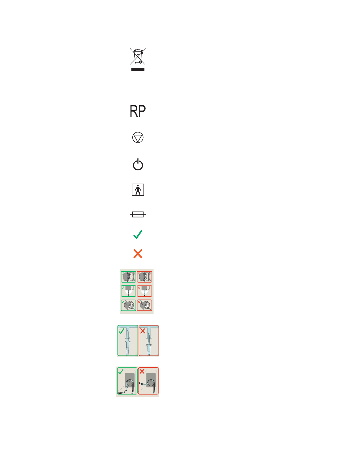
Indicates separate collection for electrical and electronic equipment per directive 2002/96/EEC.
The Intego™ PET Infusion System is a Class 1 electrical device as
determined by IEC 60601-1.
Radiopharmaceutical (
Stop button.
On/Shutdown/Standby button.
Applied parts rating. The infusion system is a BF applied part
device as determined by IEC 60601-1, indicating the degree of
protection against electric shock.
Fuse rating. See Intego address label for specific fuse rating information.
This symbol informs the user of the correct manner of use.
This symbol informs the user of the incorrect manner of use.
18
F-FDG or 18F-NaF).
Label showing the correct and incorrect routing of the Source
Administration Sets (SAS) through the Saline Pump.
Label showing the correct and incorrect insertion of the Saline
Spike into the Saline Container.
Label showing the correct and incorrect routing of the tubing
through the RP Pump.
3
Page 14

Medrad™ Intego™ PET Infusion System
Label showing the correct and incorrect direction to attach the
Needle Cartridge into the Needle Cartridge Holder.
Label showing the correct and incorrect insertion of the tubing into
the Air Detector.
Label showing the correct and incorrect orientation of the TConnector and the tubing in each of the Pinch Valves.
Label showing the correct and incorrect method of inserting the
tubing into a Pinch Valve.
The following Product Symbols apply only to INT SYS 200 systems.
Indicates Drive Speed Switch is in fast speed range position.
Indicates Drive Speed Switch is in slow speed range position.
The following Product Symbol applies only to INT SYS 100 systems.
Brake release triggers.
Warnings
Attention symbols used to identify warnings and cautions in
product labeling.
Pinch hazard. This symbol indicates there is the potential for pinch
injury.
Crush hazard. This symbol indicates there is the potential for
crush injury.
4
Page 15
1 - Introduction
1000mL
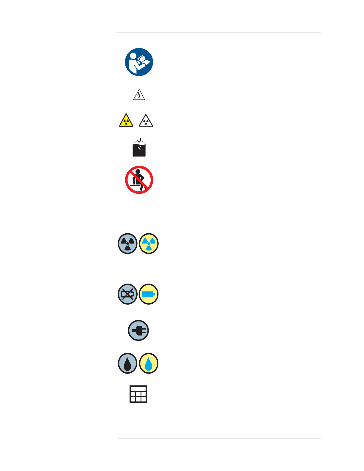
See accompanying documentation. This symbol indicates the user
should refer to the instructions-for-use to ensure safe operation.
Hazardous voltage. This symbol indicates there is a potential for
electrical shock injury.
Radiation exposure hazard. Both symbols indicate that opening
the Shielded Chamber when there is RP in the Intego™ PET
Infusion System could expose the operator or patient to radiation.
DO NOT place greater than 1000 ml Saline Container on the
Saline Hook.
Sitting on the unit is prohibited.
Display Icons
Radiation activity icon
• Not highlighted in yellow – Radioactivity may or may not be
present within the Intego™ PET Infusion System.
• Highlighted in yellow – Radioactivity is present within the
Dose Calibrator and assay information has been entered into
the Intego™ PET Infusion System.
Fluid delivery battery status icon
• Not highlighted in yellow – Battery not present or battery is
completely depleted.
• Highlighted in yellow – Unit is operating on battery power.
Plug icon
• Battery is present but the unit is operating on AC Power/
Charging.
Fluid icon
• If present, fluid is currently being pumped within the Intego™
PET Infusion System.
Calendar icon. Touch this icon to enter the desired date.
5
Page 16
Medrad™ Intego™ PET Infusion System
AM
PM
Day selector icon. Toggles between today and yesterday.
Configuration icon. Located on the configuration button; used to
open the Configuration screen.
Reset icon. Located on the reset button. Resets the RP field to the
configured default value or the current scheduled dose and resets
the patient infusion process back to entering patient information.
AM/PM icon. Press this icon to set AM or PM when entering time
data.
Approximately icon. Used to identify estimated values.
Attention icon. Used to identify items that require clinician
attention.
Partial infusion delivered.
Complete infusion delivered.
Status Indicators
The following Status Indicators are used on all Intego™ PET Infusion Systems.
System Power and Dose Calibrator Status (Green)
On – Intego™ PET Infusion System is On and Dose Calibrator is
ready for use.
Blinking – Intego™ PET Infusion System is On and Dose
Calibrator is warming up.
Off – Intego™ PET Infusion System is Shutdown.
Fluid Delivery Battery Backup Status (Amber)
On – Intego™ PET Infusion System is using battery backup.
Blinking – Only 5 minutes or less remain on battery before the
Intego™ PET Infusion System will completely Shutdown. Connect
the Intego™ PET Infusion System to AC power.
Off – Intego™ PET Infusion System is not using battery backup.
6
Page 17
The following Status Indicators apply only to the INT SYS 200 systems.
REF
Drive System Status (Blue)
On – Drive System is available for use.
Blinking – Low Drive System battery – Approximately 3 minutes or
less remain before the Drive System becomes unavailable for use.
Connect the Intego™ PET Infusion System to AC power.
Off – Drive System is not available for use.
NOTE: The Shielded Chamber Lid must be closed and
latched in order to use the Drive System.
System Battery Charging Status (Violet)
On – Batteries are charging.
Off – Batteries are not charging.
Packaging
1 - Introduction
Catalog Number.
Consult instructions for use.
Single use only.
For use with one vial of media only.
Do not use if package is opened or damaged.
Lot number.
Date of manufacture/sterilization.
Non-pyrogenic fluid path.
Fluid path sterilized using gamma radiation.
7
Page 18
Medrad™ Intego™ PET Infusion System
100% RH
5% RH
%
-20 C
o
+60 C
o
Fluid path sterilized with Ethylene Oxide.
Use by date.
Atmospheric pressure range.
Humidity range.
Temperature range.
Contains DEHP.
Do not stack.
This side up.
Keep dry.
Fragile.
8
Page 19

2 - System Basics
2 - System Basics
System Overview The Intego™ PET Infusion System delivers
PET/CT diagnostic procedure. In addition, the system provides effective radiation shielding to
18
medical personnel from
The Intego™ PET Infusion System meets the following clinical needs:
1. For a typical 555 MBq (15 mCi) infusion per patient, it limits
medical personnel to less than 60 μSv (6 mRem) finger dose and 3 μSv (0.3 mRem)
whole body dose.
2. Flexibility to program the required dose either by activity only or by activity per patient
weight.
3. Ability to deliver
measured dose, excluding Dose Calibrator calibration factor.
4. Capability to retain and print infusion history and dispensing records.
The Intego™ PET Infusion System is a self-contained, self-powered (available only on INT
SYS 200) mobile cart. A Multi-Dose Vial of RP (up to 27.75 GBq (750 mCi)) is stored within a
Shielded Chamber within the body of the system. A SAS is installed within the Shielded
Chamber at the same time a new Multi-Dose Vial of the RP indicated for use is installed. Just
prior to an infusion, the system measures a dose of RP along with a saline flush in the Dose
Calibrator. Once the correct radiation level is achieved, the RP dose and saline are infused into
the patient via a PAS. Rechargeable batteries provide sufficient power to keep the Dose
Calibrator warm so that the system can be unplugged and moved to a new location without
having to completely power Off.
F radiation exposure during nuclear medicine diagnostic procedures.
18
F-RP within ±10% of the prescribed dose and within ±2% of the
18
F-FDG or 18F-NaF to patients during a PET or
18
F radiation exposure for
The Intego™ PET Infusion System consists of the following:
1. RP Pump
2. Saline Pump
3. Dose Calibrator
4. Air Detector
5. System Shielding
6. Vial Shielding
NOTE: Radiation shielding performance is achieved by using the Vial Shield designed
by MEDRAD (or its equivalent).
9
Page 20

Medrad™ Intego™ PET Infusion System
Safety Features The Intego™ PET Infusion System incorporates the following safety features to help protect
patients and operators while the system is in use.
NOTE: These features are intended to augment the safety program of a site.
• The RP is stored in a Shielded Chamber within the Intego™ PET Infusion System. A
patient's dose of the RP indicated for use is created automatically while the dose remains
within the Shielded Chamber, greatly reducing the operator's exposure to radiation. Any
waste material left over after an infusion remains within the Shielded Chamber until time
for disposal. By employing a SAS, which is also contained within the Shielded Chamber, it
is not necessary to replace the tubing set directly connected to the Multi-Dose Vial for
each patient.
• Prior to infusing a dose of the RP indicated for use into the patient, the Intego™ PET
Infusion System measures the dose activity to ensure that the correct dosage will be
infused.
• The Intego™ PET Infusion System contains a Waste Container within the Shielded
Chamber. If it is necessary to discard a dose of RP, the dose is transferred into this Waste
Container to help prevent radiation exposure to the patient or operator.
• The Shielded Chamber Lid is secured by a heavy-duty latching system, which reduces the
likelihood of unintentionally opening the Shielded Chamber while radioactivity is contained
within. In addition, the Shielded Chamber Lid can be locked to prevent unauthorized
access to the Shielded Chamber.
•The Intego™ PET Infusion System Display can be locked to prevent unauthorized access
to the operating system.
• The Intego™ PET Infusion System has a saline test inject feature that may be used to
check vein patency prior to an infusion.
• The Intego™ PET Infusion System features an air detection system that automatically
disarms the Intego™ PET Infusion System if air is detected in the SAS.
• The Intego™ PET Infusion System PAS features a one-way check valve that prevents
backflow of fluids into the SAS.
The following is available only on INT SYS 200 systems.
• The Intego™ PET Infusion System is intended for use with a powered Drive System.
When the Drive System is being used, the system prevents test inject and dose delivery to
the patient.
The following is available only on INT SYS 100 systems.
• The Intego™ PET Infusion System employs a hydraulic braking system that is continually
engaged. The operator must continuously release the brakes to move the system.
10
Page 21
Shielded Chamber
INT SYS 100
INT SYS 200
Components
2 - System Basics
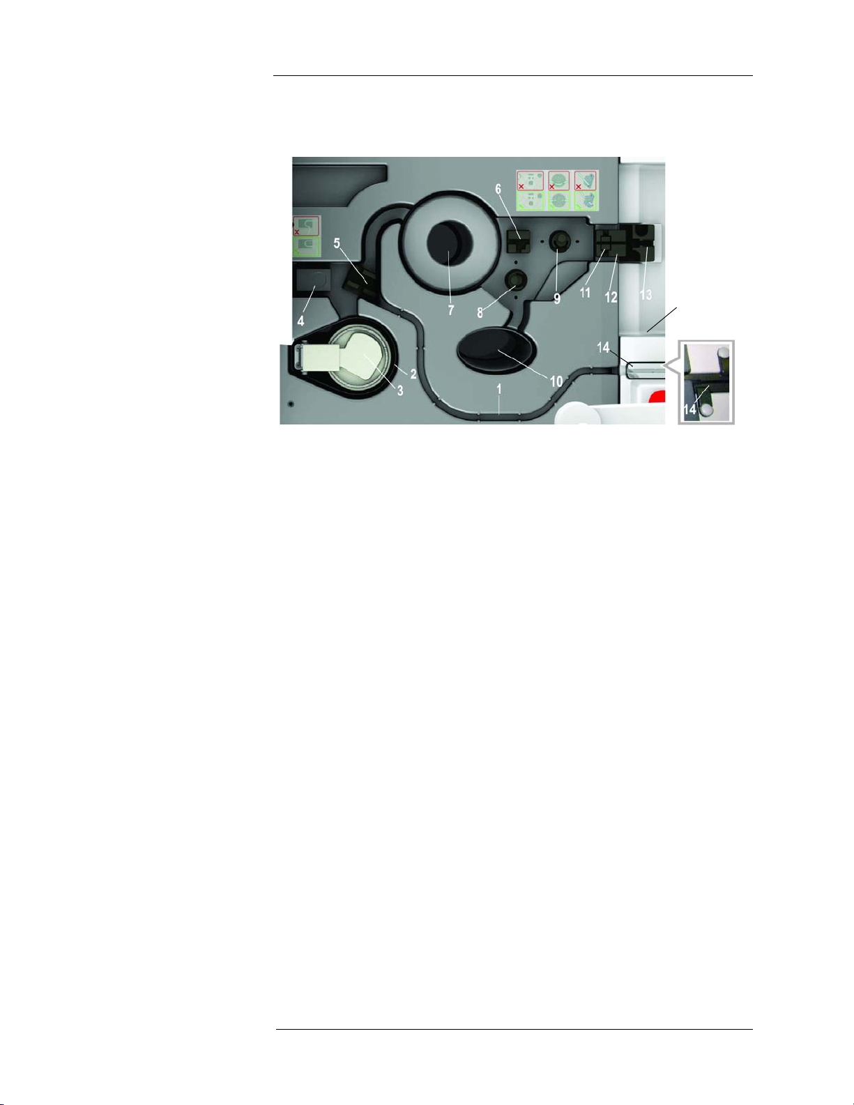
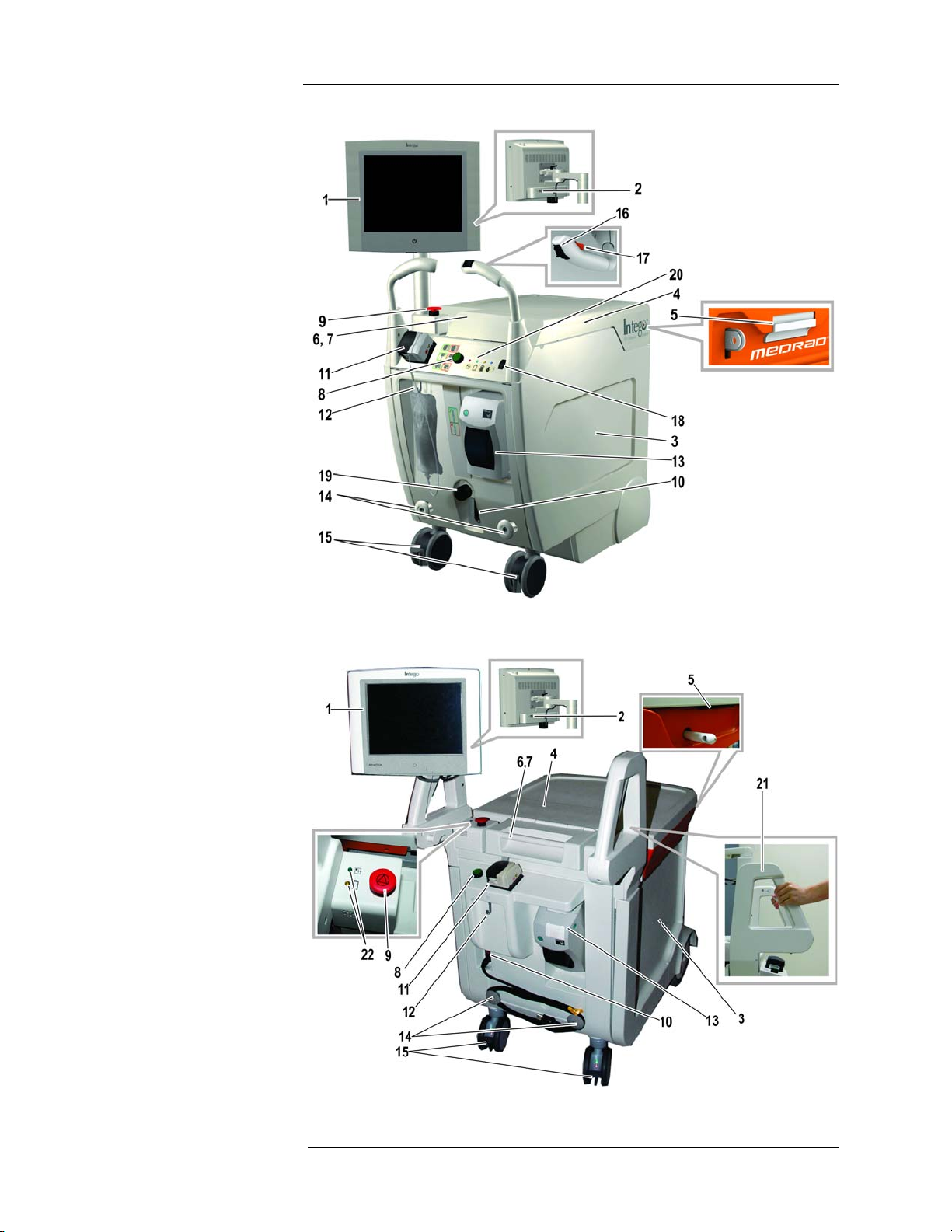
1. SAS Track – Recessed path used to hold the SAS and to prevent it from being damaged
as the Shielded Chamber Lid is opened or closed.
2. Vial Shield Compartment – The chamber where the Vial Shield is placed.
3. Needle Insertion Device – A tungsten shielded lid with a fold-down handle that holds the
SAS Needle Cartridge.
4. RP Pump – Precision pump used for RP dose preparation.
5. SAS Confluence Holder – Secures the SAS Confluence in the correct location and
orientation.
6. T-Connector Holder – Secures the SAS T-Connector in the correct location and
orientation.
7. Dose Calibrator
8. Waste Pinch Valve – Controls fluid flow to the Waste Container.
9. PAS Pinch Valve – Controls fluid flow to the PAS.
10. Waste Storage – The area where the SAS Waste Container is placed.
11. Air Detector – Used to detect air in the fluid as it passes from the SAS into the PAS.
12. Air Detector Holder – Secures the SAS within the Air Detector.
13. Swabbable Valve Holder – Secures the Swabbable Valve in the correct location for
joining the PAS and SAS together.
14. Saline Tube Holder – Holds the Saline Tube in the PAS Compartment.
11
Page 22
Medrad™ Intego™ PET Infusion System
INT SYS 100
System Components INT SYS 200
12
Page 23

2 - System Basics
1. Display – Color touch screen display used to control the Intego™ PET Infusion System,
view delivery data, and report radioactivity within the system.
2. USB Port – Provides the operator the capability of importing and exporting data.
3. Shielded Chamber – Lead shielded compartment that houses the SAS, RP, and various
other system components.
4. Shielded Chamber Lid – A sliding lid that allows access to the components and RP
contained in the Shielded Chamber.
5. Shielded Chamber Lid Latch – Used to secure the Shielded Chamber Lid from
unintentional opening.
6. PAS Compartment – not shown – A separate compartment of the Shielded Chamber.
Provides shielding for the PAS (located under the PAS Compartment Cover).
7. PAS Compartment Cover – Hinged cover to access the PAS Compartment.
8. On/Shutdown/Standby Button – Turns the Intego™ PET Infusion System On and Off.
Also used to place the Intego™ PET Infusion System into and out of Standby. Also used
to lock and unlock the system.
9. Stop Button – Used to stop current operation of the Intego™ PET Infusion System.
10. Power Switch – Rocker switch used to turn AC power On or Off.
11. Saline Pump – Peristaltic pump used to circulate saline in the SAS.
12. Saline Hook – Used for hanging the Saline Container.
13. Printer – Used to print patient-specific infusion records.
14. Cable Storage – Posts used for wrapping the power cable when the Intego™ PET
Infusion System is being moved or when not in use.
15. Caster Brakes – Used to secure the Intego™ PET Infusion System from movement when
parked.
The following apply only to INT SYS 200 systems.
16. Drive Controller – Thumb wheel to control forward/reverse variable speed.
17. Drive Engage Switch – Used to enable the Drive System.
18. Drive Speed Switch – Used to select the speed range of forward movement.
19. Drive Override – Mechanism to override the Drive System.
20. Status Indicators – Provides battery, Dose Calibrator, and Drive System status.
The following apply only to INT SYS 100 systems.
21. Brake Release – Located on each handle, used to release the primary brakes.
22. Status Indicators – Provides battery and Dose Calibrator status.
13
Page 24
Source Administration
Set (SAS) Components
Medrad™ Intego™ PET Infusion System
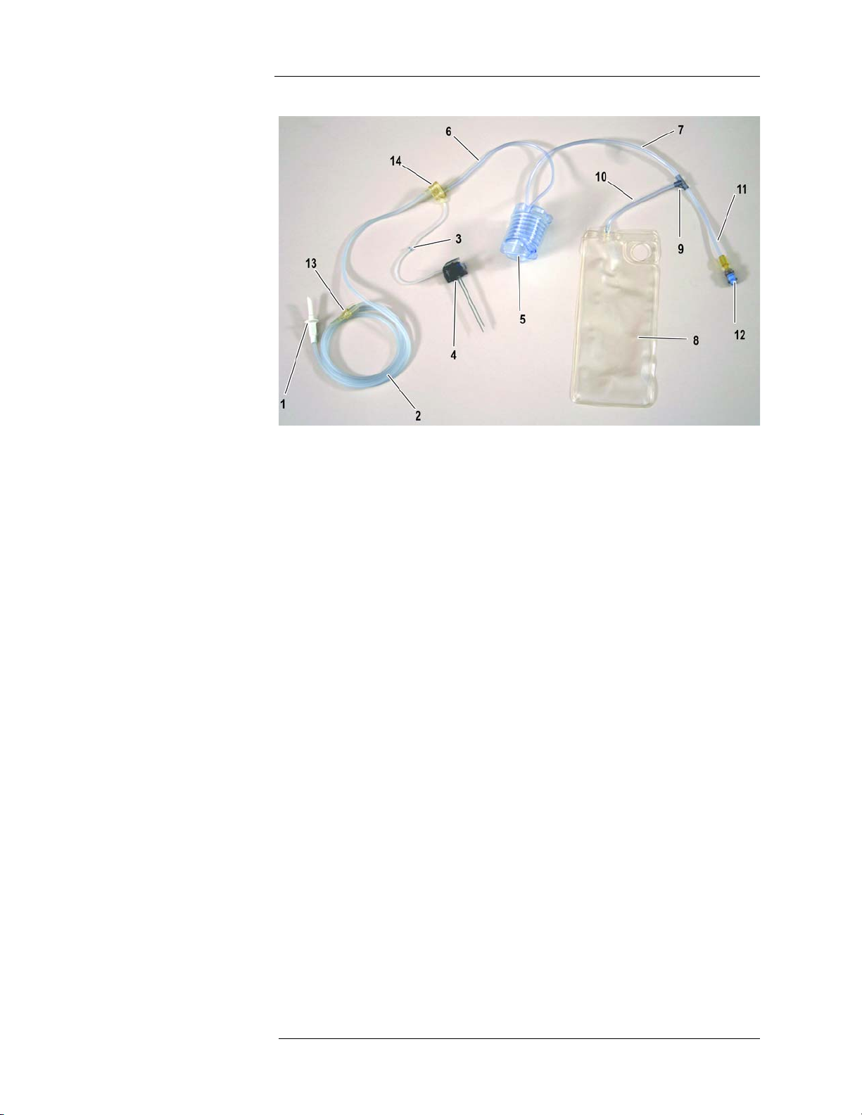
1. Saline Spike – Inserted into the Saline Container.
2. Saline Tube – Section of tube that is placed along the SAS Track and into the Saline
Pump.
3. RP Tube – Section of tube from the Needle Cartridge to the Confluence that is placed in
the RP Pump.
4. Needle Cartridge – Contains the needles used to draw the RP into the SAS.
5. SAS Coil – Inserted into the Dose Calibrator. It holds the RP dose being measured by the
Dose Calibrator.
6. Pre-Coil Tube – Section of tube from the Confluence to the SAS Coil.
7. Post-Coil Tube – Section of tube from the SAS Coil to the T-Connector.
8. Waste Container – Collects any discarded fluid.
9. T-Connector – Union of Waste Tube, Patient Tube, and the Post-Coil Tube.
10. Waste Tube – Section of tube from the T-Connector to the Waste Container.
11. Patient Tube – Section of tube from the T-Connector to the Swabbable Valve.
12. Swabbable Valve – Enables aseptic connection between the SAS and PAS.
13. Saline Disconnect Luer – Disconnects the Saline Tube from the Saline Container.
14. Confluence – Union of RP Tube, Saline Tube, and Pre-Coil Tube.
14
Page 25

Patient Administration
Set (PAS) Components
2 - System Basics
1. PAS Tubing
2. Removable Prime Tube – Captures excess saline during PAS priming.
3. One-Way Check Valve – Connected to the patient catheter or needle. Prevents fluid
backflow.
4. Luer Connector – Connects the PAS to the SAS Swabbable Valve.
15
Page 26
Vial Shield Components
1
2
3
4
Medrad™ Intego™ PET Infusion System
1. Vial Shield – Multi-Dose Vial radiation shielding vessel designed to work specifically with
the Intego™ PET Infusion System.
2. Vial Cap – Removable cap that provides access to the RP vial.
3. Access Cap – Removable cap that provides access to the RP vial septum.
4. Carrying Handle – Removable handle for transporting the Vial Shield and removing the
Access Cap.
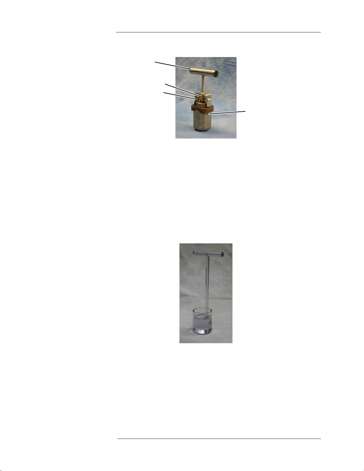
Calibration Source
Holder
NOTE: For more information regarding Vial Shields, refer to the "Appendix D - Vials and
Vial Shields."
Calibration Source Holder – Used to insert calibration sources into the Intego™ PET Infusion
System Dose Calibrator.
16
Page 27
Managing Power States Powering On the System
WARNING: To avoid risk of electric shock, this equipment must only be
connected to a supply mains with protective earth.
CAUTION: DO NOT use the Intego™ PET Infusion System immediately after it
has been brought indoors from extreme outside temperatures. Condensation
may cause electrical damage to the system. Allow the Intego™ PET Infusion System
to stabilize at room temperature before use.
1. Plug the Intego™ PET Infusion System power cable into an AC outlet and move the
Power Switch to the On position.
2. Press and hold the ON/SHUTDOWN/STANDBY button until a beep sounds. The
Introduction screen will appear.
2 - System Basics
17
Page 28
Medrad™ Intego™ PET Infusion System
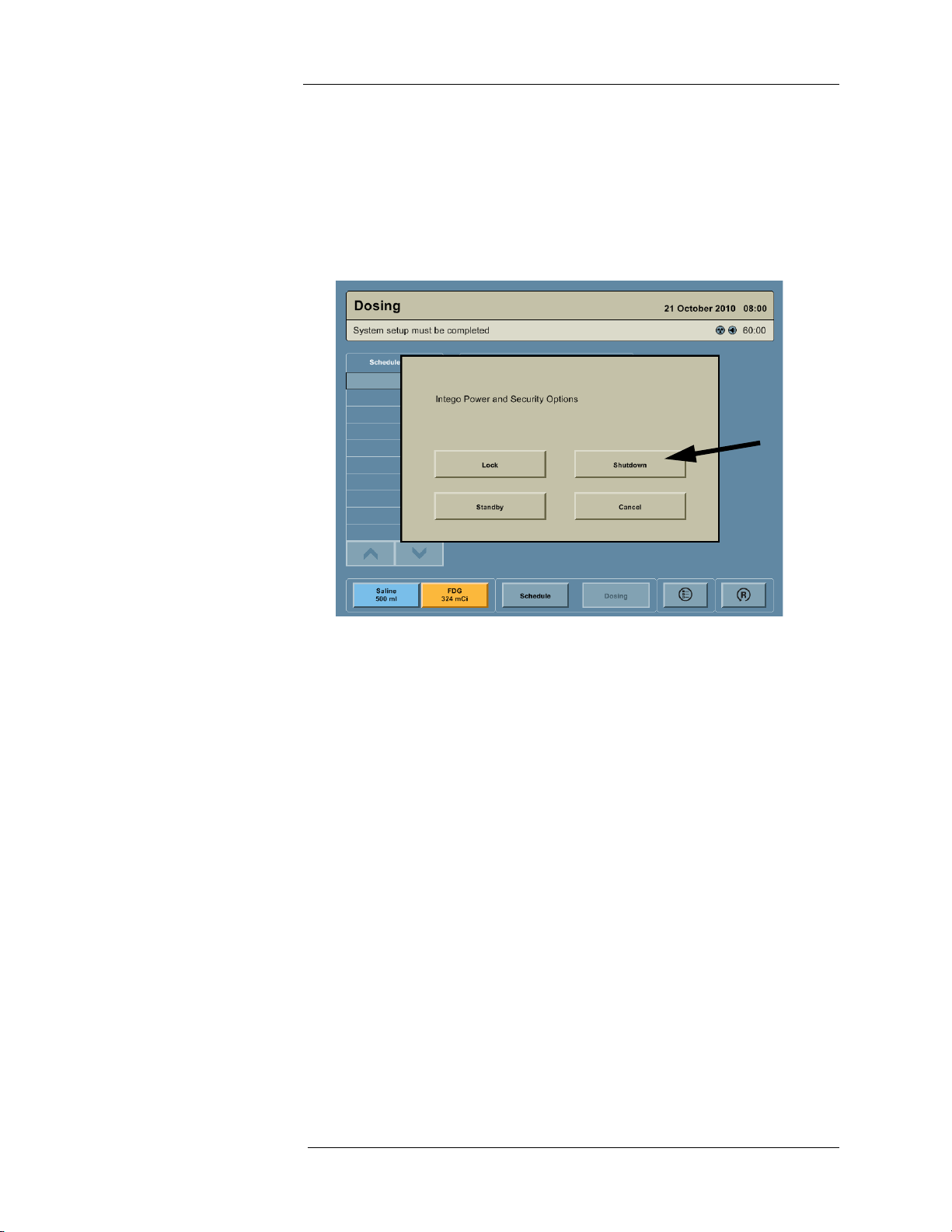
Powering Off the System
1. Press the ON/SHUTDOWN/STANDBY button.
2. A dialog box appears on the screen with the message “Intego Power and Security
Options.” Press the SHUTDOWN button.
NOTE: If the Display is not functional, the ON/SHUTDOWN/STANDBY button can be
pressed and held for 15 seconds to power Off the Intego™ PET Infusion
System.
Placing the System into Standby
1. Press the ON/SHUTDOWN/STANDBY button.
2. A dialog box appears on the screen with the message “Intego Power and Security
Options.” Press the STANDBY button.
NOTE: Placing the system into Standby eliminates the need to wait for the Dose
Calibrator to warm up and allows the system to be driven (INT SYS 200 only). If
the system is Shutdown, the user will need to wait up to 15 minutes to use the
Dose Calibrator and the INT SYS 200 systems cannot be driven.
NOTE: If the Intego™ PET Infusion System is in Standby and the power cable is not
plugged into AC power within 30 minutes, the system will completely power Off.
NOTE: If the power cable is removed from an AC outlet, the Display will remain
powered for 60 minutes. After 60 minutes, the system will automatically go into
Standby.
Taking the System out of Standby
1. Press the ON/SHUTDOWN/STANDBY button to activate the Intego™ PET Infusion
System.
18
Page 29
2 - System Basics
Securing the Intego™
PET Infusion
System
The Device Lock feature secures the display and disables the Drive System (for INT SYS 200
only). A Standard lock can be used to secure the Shielded Chamber.
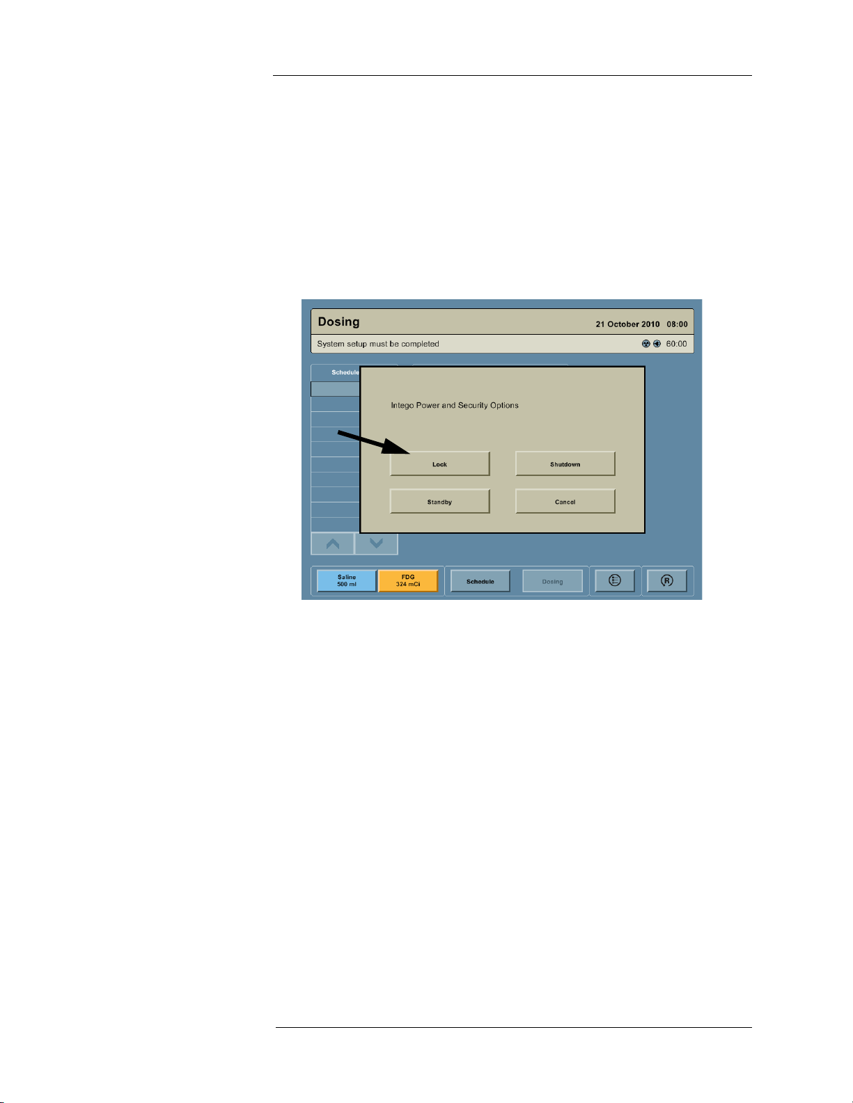
Locking the Device
NOTE: To enable the Device Lock feature, see "System Configuration."
1. Press the ON/SHUTDOWN/STANDBY button.
2. A dialog box appears on the screen with the message “Intego Power and Security
Options.” Press the LOCK button. A dialog box appears on the screen with the message
“Device Locked.”
19
Page 30
Medrad™ Intego™ PET Infusion System
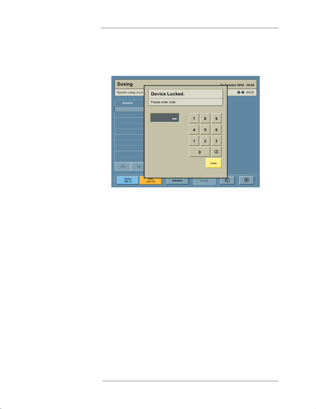
Unlocking the Device
1. If the Intego™ PET Infusion System is powered Off or in Standby, press the ON/
SHUTDOWN/STANDBY button.
2. In the “Device Locked” dialog box, enter the four digit security code and press the ENTER
button
NOTE: The factory set Security Code is 7237. It can be used to override any user
configured code.
20
Page 31

2 - System Basics
Locking the Shielded Chamber
A standard lock can be inserted in the mechanism shown below, if locking the Shielded
Chamber is desired.
INT SYS 200
INT SYS 100
21
Page 32

Medrad™ Intego™ PET Infusion System
6
1
2
3
4
5
7
Navigating the User
Interface
This section provides an overview of the main screens the operator will use with the Intego™
PET Infusion System.
Screen Overview
1. Title Bar – Located at the top of the screen. It identifies the current screen: System
Preparation, Schedule, Dosing, or Configuration.
2. Status Bar – Located below the title bar. Information about the current state during
operation is displayed here.
3. Navigation Bar – Located at the bottom left of the screen. It is used to move among the
System Preparation, Schedule, and Dosing screens. Press the SALINE button or the RP
button to access the System Preparation screen.
4. Configuration Button – Located at the bottom center of the screen. It is used to access
the Configuration screen.
5. Reset Button – Appears only on the Dosing screen. Located at the bottom right of the
screen. It resets the RP field to the configured default value or the current scheduled dose
and returns the user to the Patient Information panel.
6. Status Icons – Located at the top right of the screen. Refer to "User Interface Symbols
and Icons" section of this manual
7. Battery Meter – Located at the top right of the screen. Indicates the amount of time that
the system will operate on battery power.
22
Page 33

2 - System Basics
System Preparation Screen
This screen enables the user to enter RP assay and saline information. The Multi-Dose Vial
data, Saline Container remaining volume, activity in the SAS tubing, and the volume and
activity contained in the Waste Container are monitored from the System Preparation screen.
Daily QC and SAS priming are initiated from this screen.
Schedule Screen
This screen enables the user to manually enter the Multi-Dose Vial schedule, import the MultiDose Vial schedule via a USB memory device, export the patient infusion history via a USB
memory device, and clear the Multi-Dose Vial schedule.
23
Page 34

Medrad™ Intego™ PET Infusion System
Dosing Screen
This screen enables the user to monitor the Multi-Dose Vial schedule, prepare and deliver the
patient dose using Personalized Dosing or Manual Dosing, enter patient and operator data,
prime the PAS, perform test injections, change the flow rate, and monitor the RP activity being
delivered to the patient.
Configuration Screen
This screen enables the user to set preferences, such as language, date and time, units, audio
level, default values, security code, and Personalized Dosing formulas. Daily QC source assay
information is entered on the Configuration screen. Dose Calibrator quarterly linearity and
yearly calibration, and pinch valve calibration are performed from the Configuration screen.
NOTE: The Navigation Bar does not appear on the Configuration screen. To navigate
from the Configuration screen, it is necessary to press the OK button. The user
will be returned to the screen being used prior to the Configuration screen.
24
Page 35

2 - System Basics
Moving the Intego™ PET
Infusion System INT SYS
200
WARNING: Injury or damage to the system may occur if it is moved without the
Shielded Chamber Lid secured. Do not move system unless the Shielded Chamber
Lid is latched.
WARNING: Injury or damage may occur if the Intego™ PET Infusion System is
used on steep inclines. Do not use the system on a floor with an incline greater than
10 degrees.
WARNING: Radiation exposure hazard. Do not move the Intego™ PET Infusion
System unless the Shielded Chamber Lid is latched.
WARNING: Trip hazard. Injury may occur. Do not operate Drive System if the power
cable is plugged into an AC outlet.
CAUTION: DO NOT plug the Intego™ PET Infusion System power cable into an
extension cord or multi-outlet power strip. Only use the power cable supplied with
the system.
CAUTION: DO NOT hang clothing or other pieces of equipment from the
Intego™ PET Infusion System. Hanging clothes or equipment may impair the
movement of the system.
CAUTION: DO NOT move any portion of the Intego™ PET Infusion System by
force without disengaging the Caster Brakes or Brake Release.
1. Disconnect the PAS from the patient.
WARNING: Injury to patient may occur if system is moved without
disconnecting the PAS from the patient. Disconnect the PAS from the patient prior
to moving the Intego™ PET Infusion System.
2. Unplug the power cable from the AC outlet and wrap the power cable on the Cable
Storage.
NOTE: If the Intego™ PET Infusion System is not placed in Standby and the power
cable is unplugged from the AC outlet, the Display will remain powered for up to
60 minutes after which the system will go into Standby.
NOTE: If the Intego™ PET Infusion System is in Standby and the power cable is not
plugged into AC power within 30 minutes, the Intego™ PET Infusion System will
completely Shutdown.
3. Disengage the Caster Brakes
NOTE: The Intego™ PET Infusion System cannot be moved using the Drive System if
the Device Lock feature is enabled and the Display is locked.
NOTE: The Intego™ PET Infusion System cannot be moved using the Drive System
unless the Shielded Chamber Lid is closed and the Shielded Chamber Lid Latch
is engaged.
NOTE: The Drive System cannot be engaged when priming the SAS or PAS,
performing a test injection, preparing an RP dose, or delivering an RP dose to
the patient or Waste Container.
25
Page 36

Medrad™ Intego™ PET Infusion System
NOTE: The Intego™ PET Infusion System must be powered On or in Standby to use
the Drive System. If the system is powered Off, the Drive System will not
operate.
NOTE: The battery must be charged for the Drive System to function. The blue Status
Indicator will be illuminated when the Drive System is available for use. If the
blue Status Indicator is blinking, plug the Intego™ PET Infusion System power
cable into an AC outlet to charge the battery.
4. Choose either slow or fast on the Drive Speed Switch.
5. Firmly grip both of the handles on the Intego™ PET Infusion System at the Operator
Position. Squeeze the Drive Engage Switch.
6. To move forward, use the thumb of the right hand to slowly rotate the Drive Controller
forward while keeping the Drive Engage Switch pressed. To move backward, use the
thumb of the right hand to slowly rotate the Drive Controller backward while keeping the
Drive Engage Switch pressed.
NOTE: If the blue Status Indicator begins blinking while moving the Intego™ PET
Infusion System, there are approximately 3 minutes remaining before the Drive
System will stop functioning. When the blue Status Indicator begins blinking,
move the system to an AC outlet and plug in the power cable.
7. Move the Intego™ PET Infusion System by carefully pushing the handles to the left and
right to steer. The speed can be varied using the Drive Controller. The further the Drive
Controller is rotated from the center position, the faster the system will move.
CAUTION: Avoid making fast turns or sudden starts and stops.
NOTE: Use forward motion to cross thresholds while moving the Intego™ PET Infusion
System.
8. Once the Intego™ PET Infusion System is in its new location, release the Drive Engage
Switch or the Drive Controller to stop.
9. Apply the Caster Brakes.
10. Unwrap the power cable from the Cable Storage and plug into an AC outlet.
NOTE: To ensure that the battery is fully charged and has the maximum capacity, keep
the Intego™ PET Infusion System connected to AC power at all times except
when the system is being moved.
Moving the System Using the Drive Override (For Emergency Use Only)
NOTE: If the Drive System is not available, the Intego™ PET Infusion System can be
moved by using the Drive Override.
1. Disconnect PAS from patient.
2. Unplug the power cable from the AC Outlet. Wrap the power cable on the Cable Storage.
26
Page 37

2 - System Basics
3. Pull the Drive Override out until it is fully extended (approximately 15 cm (6 inches)).
4. Disengage the Caster Brakes.
WARNING: Crush hazard. Using the Drive Override disengages the Drive
System brakes. Ensure the Intego™ PET Infusion System is not on an incline or left
unattended when using the Drive Override and re-engage the Drive Override after
moving the system and engage the Caster Brakes.
Moving the Intego™ PET
Infusion System INT SYS
100
5. Firmly grip both handles on the Operator Position of the Intego™ PET Infusion System.
6. Move the Intego™ PET Infusion System using firm, steady force. Avoid making jerking
movements or sudden starts and stops. Leave approximately 1 m (3 ft) per side to
complete turns.
7. Once the Intego™ PET Infusion System is in its new location, apply the Caster Brakes.
8. Push the Drive Override in to the normal operating position.
9. Unwrap the power cable from the Cable Storage and plug into an AC outlet.
WARNING: Injury or damage to the system may occur if it is moved without the
Shielded Chamber Lid secured. Do not move system unless the Shielded Chamber
Lid is latched.
WARNING: Injury or damage may occur if the Intego™ PET Infusion System is
used on steep inclines. DO NOT use the system on a floor with an incline greater
than 10 degrees.
WARNING: Radiation exposure hazard. Do not move the Intego™ PET Infusion
System unless the Shielded Chamber Lid is latched.
CAUTION: DO NOT plug the Intego™ PET Infusion System power cable into an
extension cord or multi-outlet power strip. Only use the power cable supplied with
the system.
CAUTION: DO NOT hang clothing or other pieces of equipment from the
Intego™ PET Infusion System. Hanging clothes or equipment may impair the
movement of the system.
CAUTION: DO NOT move any portion of the Intego™ PET Infusion System by
force without disengaging the Caster Brakes or Brake Release.
27
Page 38

Medrad™ Intego™ PET Infusion System
1. Disconnect the PAS from the patient.
WARNING: Injury to patient may occur if system is moved without
disconnecting the PAS from the patient. Disconnect the PAS from the patient prior
to moving the Intego™ PET Infusion System.
NOTE: If the Intego™ PET Infusion System is not placed in Standby and the power
cable is unplugged from the AC outlet, the Display will remain powered for three
minutes. If the power cable is not plugged into the AC outlet within three
minutes, the system will go into Standby.
NOTE: If the Intego™ PET Infusion System is in Standby and the power cable is not
plugged into AC power within 30 minutes, the system will completely power Off.
2. Unplug the power cable from the AC outlet and wrap the power cable on the Cable
Storage.
3. Disengage the Caster Brakes
4. Firmly grip both handles on the Operator Position of the Intego™ PET Infusion System.
Squeeze the Brake Release on each handle to disengage the brakes.
NOTE: The Brake Release on each handle must be squeezed simultaneously to
disengage the brakes.
NOTE: To engage the brakes, stop squeezing either Brake Release.
5. Move the Intego™ PET Infusion System using firm, steady force. Avoid making jerking
movements or sudden starts and stops. Leave approximately 1 m (3 ft) per side to
complete turns.
6. Once the Intego™ PET Infusion System is in its new location, stop squeezing the Brake
Release to stop.
7. Apply the Caster Brakes.
8. Unwrap the power cable from the Cable Storage and plug into an AC outlet.
28
Page 39

3 - System Configuration
3 - System Configuration
To configure the Intego™ PET Infusion System, press the CONFIGURATION button on the
Navigation Bar.
NOTE: To save configuration changes, press the OK button. To return to the factory
settings, press the DEFAULT button.
System Settings On the left side of the Configuration screen, press the SYSTEM button to access the
configuration options. Languages, Date/Time, Units, and Audio tabs will be displayed along the
top.
1. Press the Languages tab to access the language configuration options.
a. Configure the Intego™ PET Infusion System by pressing the button with the desired
language.
29
Page 40

Medrad™ Intego™ PET Infusion System
2. Press the Date/Time tab to access the date and time configuration options.
a. Configure the date format by pressing the Date Format field. Five date formats will be
displayed. Press the button showing the desired date format.
b. Configure the time format by pressing the Time Format field. A 12-hour and a 24-
hour format will be displayed. Press the button showing the desired time format.
c. Configure the current date and time by pressing the EDIT button. The current date is
entered by pressing the Calendar icon. The current time is entered by pressing the
Current Time field.
NOTE: The system does not automatically adjust for Daylight Savings Time. The
system time must be adjusted manually.
3. Press the Units tab to access the weight and activity unit configuration options.
30
Page 41

3 - System Configuration
a. Configure the weight units by pressing either the POUNDS button or the
KILOGRAMS button.
b. Configure the activity units by pressing either the CURIE button or the BECQUEREL
button.
4. Press the Audio tab to access the audio configuration options.
a. Configure the audio level by pressing the HIGH button, NORMAL button, or LOW
button.
Dosing Settings On the left side of the Configuration screen, press the DOSING button to access the dosing
options. RP, Saline, Case, and Printing tabs will be displayed along the top.
1. Press the RP tab to access the RP configuration options.
31
Page 42

Medrad™ Intego™ PET Infusion System
a. Configure the default dose by pressing the Default Dose field and entering the
desired value via the keypad.
NOTE: If a vial schedule is entered using the Schedule screen, the Default Dose will be
overridden with the schedule value. For more information on when the Default
Dose is used and how a user may override it, refer to the "Patient Infusion"
section.
b. Configure the Intego™ PET Infusion System to use Personalized Dosing by default
by pressing the Default Setting ON button.
c. Configure the Intego™ PET Infusion System to use Manual Dosing by default by
pressing the Default Setting OFF button.
d. Up to five Personalized Dosing formulas can be entered by pressing the EDIT
FORMULAS button.
i. Press the Multiplier field to enter the RP activity per unit weight and then press
ENTER on the numeric keypad.
ii. Press the Minimum field to enter the minimum RP activity that can be prepared
regardless of the patient weight and then press ENTER on the numeric keypad.
iii. Press the Maximum field to enter the maximum RP activity that can be prepared
regardless of the patient weight and then press ENTER on the numeric keypad.
iv. Press the OK button.
NOTE: If more than one formula is created, a formula name must be entered when
entering the data. Press a NEW FORMULA button and enter the formula name
via the keypad.
NOTE: At least one formula must be entered to use the Personalized Dosing.
32
Page 43

3 - System Configuration
2. Press the Saline tab to access the saline configuration options.
a. Configure the default Saline Container volume by pressing the Default Volume field
and entering the desired value via the keypad.
b. Configure the additional flush volume by pressing the Additional Flush Volume field
and entering the desired value via the keypad.
WARNING: Injury or death may result from injecting air. If an additional flush
volume is used with extension tubing, the Intego™ PET Infusion System will not prime
the additional tubing automatically. Air may be injected into the patient if the extension
tubing is not primed before use. The additional tubing must be primed before
connecting to the patient by selecting the “Prime PAS” function until all air is purged
from the PAS.
NOTE: The additional flush volume is added to the fixed 35 ml saline flush used during
a patient infusion.
c. Configure the test inject volume by pressing the Test Inject Volume field and entering
the desired value via the keypad.
d. Configure the default flow rate by pressing either the 1.0mL/s or 0.5mL/s button.
33
Page 44

Medrad™ Intego™ PET Infusion System
3. Press the Case tab to access the Case configuration options.
a. Configure the Intego™ PET Infusion System by pressing the button with the desired
default infusion site.
NOTE: If a default infusion site is not configured, the user will be given the option to
select the infusion site when entering patient information on the Dosing screen.
If a default infusion site is configured, it can be overridden when entering patient
information on the Dosing screen.
4. Press the Printing tab to access the Printing configuration options.
a. Configure the Auto Print by pressing the ON or OFF button.
b. Press the Quantity field and enter the desired number of labels to automatically be
printed if the Auto Print option is set to On.
NOTE: If the Auto Print option is not configured to be On to print labels, the user may
still print manually.
34
Page 45

3 - System Configuration
Maintenance Settings 1. On the left side of the Configuration screen, press the MAINTENANCE button to access
the maintenance options. Daily QC, Linearity, Calibration, and Service tabs will be
displayed along the top.
2. Press the Daily QC tab to access the Daily QC configuration options.
a. Press the Lot Number field and enter the lot number of the
137
Cs calibration source
to be used for Daily QC.
b. Press the Activity field and enter the activity of the
137
Cs calibration source to be
used for Daily QC.
c. Press the EDIT button to enter the assay date and time.
d. Press the Calendar icon next to the Reference Date and enter the assay date of the
137
Cs calibration source to be used for Daily QC.
NOTE: When reading the date from the
137
Cs calibration source assay information, be
cognizant of the format. Some formats are dd/mm/yy and others are mm/dd/yy.
e. Press the Reference Time field and enter the assay time of the
137
Cs calibration
source to be used for daily QC. If a time is not included with the assay information,
enter 12:00.
NOTE: Pressing the Linearity and Calibration tabs will access these configuration
screens. Descriptions on how to perform linearity testing, pinch valve, and
yearly calibration are provided in the Cleaning and Maintenance Appendix.
35
Page 46

Medrad™ Intego™ PET Infusion System
3. Press the Service tab to access the service configuration options.
a. To configure a MEDRAD Service reminder, press the Calendar icon next to the
Reminder Date field and enter the desired date.
b. To export log files, insert a USB memory device into the USB Port. Press either the
30 DAYS or ALL LOGS button, then remove the USB Memory device after the
Intego™ PET Infusion System indicates the export is complete.
WARNING: Shock hazard. This port is intended for connection of USB-powered
devices, such as memory sticks, having no other electrical power connections.
Connection of devices having other electrical power connections to this port may
result in an electrical shock hazard.
c. MEDRAD contact information is on the Service Configuration screen.
36
Page 47

3 - System Configuration
Security Settings 1. On the left side of the Configuration screen, press the SECURITY button to access the
security options. A Manage Security Code dialog box will appear.
2. Under Device Lock, press the ON button to enable the Device Lock feature. Press the
OFF button to disable the Device Lock feature.
NOTE: Locking the device prevents unauthorized use or movement of the Intego™
PET Infusion System (for INT SYS 200 only) and requires a user to enter the
default or a user-specific security code after powering On.
3. To create a unique security code, enter the current security code by pressing the Current
Code field. The factory set security code is 7237. It can be used to override any user
configured code. If the current user code is unknown, enter 7237 in the Current Code
field.
4. Press the Enter New Code field. Enter a unique four digit security code.
5. Press the Re-enter New Code field. Enter the same four digit security code.
37
Page 48

Medrad™ Intego™ PET Infusion System
6. Press the ENTER button. The OK button will appear. Press OK to accept the new code.
38
Page 49

4 - Daily Setup
Placing the System into
Clinical Mode
4 - Daily Setup
WARNING: Patient injury could result from using improper components. Use
only components and options provided by MEDRAD designed for Intego™ PET
Infusion System.
WARNING: Explosion hazard. DO NOT use the Intego™ PET Infusion System
when flammable gases are present. Patient injury could result from using the
system in the presence of flammable gases (such as anesthetics).
WARNING: Trip hazard. Injury may occur. Do not operate Drive System if the power
cable is plugged into an AC outlet.
WARNING: No modification of this equipment is allowed.
WARNING: Do not use the Intego™ PET Infusion System in an oxygen rich
environment (Environment in which the concentration of oxygen is greater than 25%
for ambient pressures up to 110kpa).
1. Power On the Intego™ PET Infusion System.
NOTE: If the Device Lock feature has been enabled, the Intego™ PET Infusion System
will prompt the user to enter the Security Code. Press ENTER when complete.
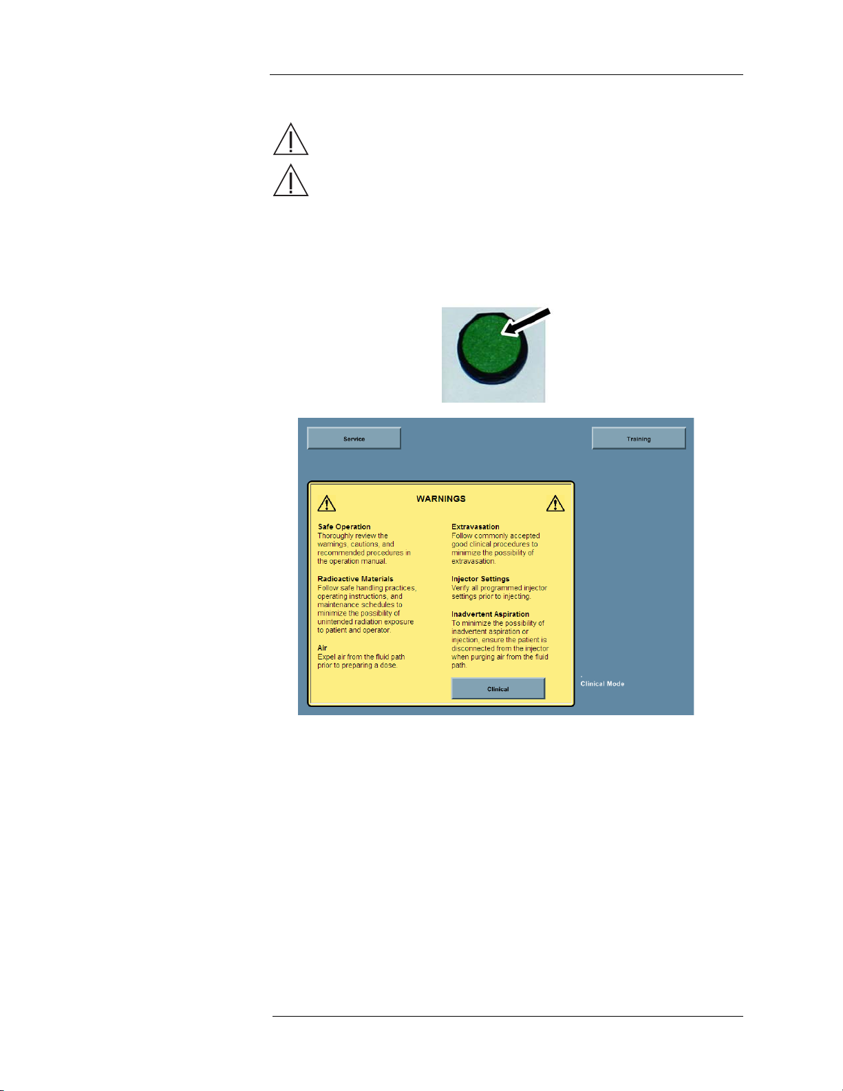
2. The Introduction screen appears. Press the CLINICAL button.
NOTE: The screen displays the current mode in the lower right corner of the
Introduction screen.
39
Page 50

Medrad™ Intego™ PET Infusion System
3. If the Intego™ PET Infusion System was in Training Mode, the system will display the
message “Changing from Training Mode to Clinical Mode requires a restart. Continue?”
Press OK to proceed.
4. The Intego™ PET Infusion System will display a progress bar while switching to Clinical
Mode. When complete, the system will display a message prompting the user to restart.
Press the RESTART button to Restart the system.
5. At the Introduction screen, press the CLINICAL button.
40
Page 51

4 - Daily Setup
NOTE: Only screens for
18
F-FDG are shown here. When using 18F-NaF, the text “FDG”
changes to “NaF” and RP-specific screen elements change from orange to
green (e.g., the RP button on the Navigation Bar).
6. When the System Preparation screen appears, press the OK button to proceed. Allow up
to 15 minutes for the Dose Calibrator to warm up before proceeding; the Status Bar
indicates the warm-up time remaining.
Using the Schedule To access the Schedule screen, press the SCHEDULE button on the Navigation Bar. The
Multi-Dose Vial schedule can either be entered manually or imported via the USB Port. The
user may edit the schedule as it changes throughout the day.
NOTE: The Intego™ PET Infusion System may highlight scheduled RP infusions. Refer
to the "Vial Monitoring" section of this document for more information.
41
Page 52

Medrad™ Intego™ PET Infusion System
Manually Entering Schedule Information
1. Press the ADD APPOINTMENT button or a blank row in the schedule.
2. Press the Time field to enter the planned infusion time.
3. Press the Activity field to enter the planned dose activity.
4. Repeat steps 1 through 3 until schedule entry is complete.
NOTE: More than six appointments can be added. Use the scroll bar to view
appointments not on the Schedule screen.
Importing the Schedule Information via the USB Port
NOTE: Importing a schedule replaces the existing schedule.
1. Create an electronic version of the schedule named “schedule.csv” and copy it to a USB
memory device. There are three ways to create an electronic schedule:
a. MEDRAD’s MVP software tool (Recommended).
b. Select third party nuclear medicine management software packages.
c. Using a spreadsheet program or text editor.
NOTE: Please contact MEDRAD for more information about creating an electronic
schedule.
2. Insert the USB memory device into the USB Port on the Display.
3. Press the IMPORT SCHEDULE button. The time and activity information automatically
populates for all scheduled RP infusions
42
Page 53

4 - Daily Setup
.
Editing the Schedule
1. To edit a scheduled RP infusion, press the Time field or Activity field and enter the new
value.
NOTE: The Intego™ PET Infusion System automatically sorts the schedule by infusion
time. Editing infusion time may reorder the schedule.
2. To delete a scheduled infusion, press the X button.
3. To remove the entire schedule, press the CLEAR SCHEDULE button.
43
Page 54

Medrad™ Intego™ PET Infusion System
Exporting the Infusion History
The Intego™ PET Infusion System creates an infusion history as each infusion is completed.
The infusion history consists of a .csv file for each of the last 31 days the Intego™ PET Infusion
System was used. To export the infusion history, insert a USB memory device in the USB Port
and press the EXPORT HISTORY button. Remove the USB memory device when the system
indicates the export has been completed.
44
Page 55

4 - Daily Setup
Performing Daily QC The Daily QC confirms proper operation of the Dose Calibrator. Daily QC can only be
performed without a Multi-Dose Vial or SAS installed. It is possible to perform RP infusions
without valid Daily QC results, but this is not recommended. An Attention icon is displayed on
the DAILY QC button when the system is being used without valid Daily QC results.
WARNING: Using the Intego™ PET Infusion System without performing the
necessary QC processes could result in the patient receiving an incorrect
dosage of the RP indicated for use. Be certain to perform all necessary QC checks
at the recommended intervals.
1. Access the System Preparation screen by pressing the SALINE button or RP button on
the Navigation Bar.
2. Press the DAILY QC button.
NOTE: Nearby radiation sources may cause the zero adjustment to fail. Remove any
nearby radiation sources before starting daily QC.
45
Page 56

Medrad™ Intego™ PET Infusion System
3. Press the START button. The Intego™ PET Infusion System will automatically proceed
with all listed Daily QC tests and check the box next to each test as it completes.
NOTE: The Bias Adjustment may compensate for a failed Zero Adjustment. The Daily
QC is valid if the Zero Adjustment fails but the Bias Adjustment is successful.
4. If the Zero Adjustment fails, check for and remove any nearby sources of radiation and
repeat the Daily QC test from Step 3.
5. Daily QC will pause at the Constancy/Accuracy test and produce the prompt shown
below.
a. If the
137
Cs calibration source is not available, press the SKIP button to bypass the
Constancy/Accuracy test and proceed to step 10.
b. If the
137
Cs calibration source is available but the displayed assay information is
incorrect, press the EDIT button, update the assay information, and proceed to step
6.
46
Page 57

4 - Daily Setup
NOTE: When the
137
Cs calibration source lot number is changed, the Constancy check
will establish a new reference activity for future Constancy checks instead of
testing Constancy against the previous reference.
6. Grasp the Shielded Chamber Lid Latch to release it, and open the Shielded Chamber Lid
to gain access to the Shielded Chamber.
7. Place the
137
Cs calibration source into the Dose Calibrator using the Calibration Source
Holder.
8. Close the Shielded Chamber Lid until the Shielded Chamber Lid Latch engages, then
press the OK button.
9. When prompted, open the Shielded Chamber Lid, remove the test source from the Dose
Calibrator, slide the Shielded Chamber Lid closed until the Shielded Chamber Lid Latch
engages, then press the OK button.
47
Page 58

Medrad™ Intego™ PET Infusion System
10. At the conclusion of the Daily QC, the Intego™ PET Infusion System displays a summary
screen. Print this screen to keep with the system's records.
11. Press the SUMMARY button to return to the main System Preparation screen.
Entering RP Assay and
Saline Information
WARNING: Radiation exposure hazard. Do not insert more than
27.75 GBq (750 mCi) into the Intego™ PET Infusion System.
NOTE: Entering RP Assay and Saline Information may be performed before or after
Installing the SAS or Installing the Multi-Dose Vial.
1. Access the System Preparation screen by pressing the SALINE or RP buttons on the
Navigation Bar.
2. If a Multi-Dose Vial is loaded in the Intego™ PET Infusion System, remove the Vial Shield
and SAS, then press the REMOVE button.
3. Press the NEW button to enter RP Assay information.
48
Page 59

4 - Daily Setup
4. The Vial Assay Information screen appears. Press the respective fields to enter the Lot
Number, Date, Reference Time, RP Type, Activity at Reference Time, and Volume. When
all data is entered, press the OK button.
WARNING: Radiation exposure hazard. Do not insert more than
27.75 GBq (750 mCi) into the Intego™ PET Infusion System.
NOTE: If the level of radioactivity in the Multi-Dose Vial exceeds 27.75 GBq (750 mCi),
the Intego™ PET Infusion System displays the message “Vial activity exceeds
safe shielding level. Immediately return vial to protective container.” If this
message appears, remove the Vial Shield from the system and return to hot lab
or other storage capable of providing adequate shielding for the contained
activity.
5. The System Preparation screen reappears with the usable activity in the Multi-Dose Vial
displayed within the vial symbol. The total Multi-Dose Vial volume and activity are
displayed to the right of the vial symbol.
49
Page 60

Medrad™ Intego™ PET Infusion System
6. Press the REPLACE button in the Saline section.
7. Enter the volume of the Saline Container using the keypad.
NOTE: The minimum recommended Saline Container volume is 750 ml.
Installing the SAS NOTE: Always install a new SAS before installing a new Multi-Dose Vial.
18
NOTE: The Intego™ PET Infusion System is intended for use with
NaF. Intego™ PET Infusion System disposables intended for use with
18
may be used to deliver
F-FDG or 18F-NaF. Please contact MEDRAD for more
information.
NOTE: Installing the SAS or installing the Multi-Dose Vial may be performed before or
after entering RP Assay and Saline Information.
NOTE: In the following steps, it will be helpful to refer to the diagrams of the Intego
Infusion System Components, Intego Shielded Chamber Components, and the
SAS Components.
WARNING: DO NOT use the SAS with more than one Multi-Dose Vial. Using the
SAS with more than one Multi-Dose Vial could result in injury to patient or operator.
1. Place the Saline Container onto the Saline Hook at the rear of the cart.
2. Open the PAS Compartment Cover.
3. Grasp the Shielded Chamber Lid Latch to release it, and slide the Shielded Chamber Lid
towards the front of the cart to gain access to the Shielded Chamber.
WARNING: Severe operator injury can occur if care is not taken when opening
or closing the Shielded Chamber Lid or the PAS Compartment Cover. Be certain
that all fingers are clear before opening or closing the Shielded Chamber Lid or the
PAS Compartment Cover.
F-FDG and 18F-
18
F-FDG
50
Page 61

WARNING: Radiation exposure hazard. Using the Shielded Chamber Lid as a
work space may expose the operator to excess radiation.
Chamber Lid as a work space while there are
Intego™ PET Infusion System
placing items on the Shielded Chamber Lid while it is open may damage the Shielded
Chamber Lid, hampering its ability to provide an adequate radiation shield.
4. Open the SAS Disposable Package.
WARNING: Patient injury may result if disposable package is opened or
damaged, or if damaged components are used. Visually inspect contents and
package before use.
WARNING: This product contains DEHP, a chemical known to the state of
California to cause birth defects or other reproductive harm. Please visit
www.medrad.com/DEHP for more information regarding DEHP in MEDRAD products.
WARNING: Patient infection may result from the use of non-sterile components.
Maintain sterility of all disposable components using aseptic techniques.
WARNING: Only the fluid path of the set is sterile and non-pyrogenic. Do not use
in a sterile or aseptic area without proper precautions.Place the Saline Container onto
the Saline Hook at the rear of the cart.
.
4 - Daily Setup
Do not use the Shielded
radioactive materials present within the
Using the Shielded Chamber Lid as a work space or
5. Load the Needle Cartridge into the Vial Shield Compartment:
WARNING: Puncture hazard. The SAS contains needles. To prevent injury, take
care when handling the SAS to control the needles. Dispose of the needles per
individual facility guidelines.
a. Grasp the Needle Insertion Device’s handle and lift the Needle Insertion Device
straight up until it stops.
b. Rotate the Needle Insertion Device counter-clockwise until it stops. Release the
handle. The Needle Insertion Device will remain in position.
c. Lift the hinged Needle Insertion Device cover to access the Needle Cartridge Holder.
51
Page 62

Medrad™ Intego™ PET Infusion System
d. Insert the Needle Cartridge into the holder so the RP Tube exits the cartridge away
from the holder.
e. Stow the needles safely in the Vial Compartment until ready to install the Multi-Dose
Vial by lowering the Needle Insertion Device cover, rotating the Needle Insertion
Device clockwise until it stops, then pushing down on the Needle Insertion Device
until it is back in its original position.
6. Insert RP Tube in the RP Pump:
a. Open the RP Pump door.
b. Insert the RP Tube into the RP Pump as shown in the left panel below. For proper
installation, the tubing collar must rest immediately outside the RP Pump on the side
closest to the Vial Shield Compartment.
c. Close the RP Pump door.
CAUTION: Incorrect installation of the SAS may result in improper functioning
of the Intego™ PET Infusion System.
7. Insert the Confluence into the SAS Confluence Holder.
52
Page 63

4 - Daily Setup
8. Insert the SAS Coil into the Dose Calibrator. Be sure the Pre-Coil Tube enters and the
Post-Coil Tube exits on top of the SAS Coil and the SAS Coil is placed at the bottom of the
Dose Calibrator.
9. Route the Pre-Coil Tube into the SAS track between the SAS confluence holder and the
Dose Calibrator. Be sure to press the tubing firmly into the SAS track.
10. Unroll the Waste Container and insert it into the Waste Storage.
11. Place the T-Connector into the T-Connector Holder.
12. Install the Waste Tube into the Waste Pinch Valve. Install the Patient Tube into the PAS
Pinch Valve.
NOTE: To install tubing in a Pinch Valve, open the valve by pressing the button on the
top. While holding the valve open and grasping the tubing on either side of the
valve, pull the tubing in from the side. The tubing must be inserted completely
as shown in the left panel below. Release the button on the valve to pinch the
tubing in place.
NOTE: The left panel in the picture below shows the correct layout of the SAS when the
tubing has been properly installed into the SAS T-Connector Holder, Waste
Pinch Valve, and PAS Pinch Valve.
53
Page 64

Medrad™ Intego™ PET Infusion System
CAUTION: Incorrect installation of the SAS may result in improper functioning
of the Intego™ PET Infusion System.
13. Firmly press the Patient Tube exiting the PAS Pinch Valve into the Air Detector Holder and
Air Detector. Insert the Swabbable Valve into the Swabbable Valve Holder.
NOTE: Make certain the tubing is fully inserted into the Air Detector as illustrated below.
CAUTION: Incorrect installation of the SAS may result in improper functioning
of the Intego™ PET Infusion System.
14. Insert the Saline Spike into the Saline Container. Verify the Saline Spike is fully inserted
into the container as illustrated below.
CAUTION: Incorrect installation of the SAS may result in improper functioning
of the Intego™ PET Infusion System.
15. Open the Saline Pump door, install the Saline Tube, then close the Saline Pump door.
54
Page 65

4 - Daily Setup
a. Center the Saline Tube on the Saline Pump rollers. The Saline Pump will not pump
fluid properly if the tubing falls below the rollers.
CAUTION: Incorrect installation of the SAS may result in improper functioning
of the Intego™ PET Infusion System.
b. Ensure the Saline Disconnect Luer rests against the edge of the Saline Pump.
CAUTION: Incorrect installation of the SAS may result in improper functioning
of the Intego™ PET Infusion System.
c. Center the Saline Tube in the Saline Pump door to prevent the tubing from being
pinched when the door is closed.
CAUTION: Incorrect installation of the SAS may result in improper functioning
of the Intego™ PET Infusion System.
WARNING: Air embolism or improper injection dosage may occur if Saline Line
is damaged. Make certain the Saline Tube is not pinched within the Saline Pump as
this may damage the administration set.
55
Page 66

Medrad™ Intego™ PET Infusion System
16. Route the Saline Tube along the SAS Track, starting at the SAS Confluence Holder and
moving towards the Saline Pump. Be sure to press the tubing firmly into the SAS Track.
17. Press the Saline Tube into the Saline Tube Holder between the Saline Pump and SAS
Track.
INT SYS 200
INT SYS 100
WARNING: Improper injection dosage or radiation spillage may result if the
Shielded Chamber Lid is closed onto the tubing set. Ensure that the tubing set
and all administration set components are properly installed before closing the
Shielded Chamber Lid.
18. Once the SAS has been installed, ensure all components are laying flat prior to closing
the lid.
56
Page 67

4 - Daily Setup
Installing the Multi-Dose
Vial
WARNING: DO NOT use any RP other than 18F-FDG or 18F-NaF with the Intego™
18
PET Infusion System. Use of radiopharmaceuticals other than
F-FDG or 18F-NaF
may cause inaccurate dose measurement and/or excessive radioactive exposure.
WARNING: Radiation exposure hazard.
18
F-FDG or 18F-NaF emit gamma
radiation. Operator should exercise extreme caution when handling
radiopharmaceuticals. Doses may exceed maximum permissible dose if appropriate
precautions are not properly exercised. Follow all individual facility guidelines for the
handling and disposal of radioactive materials. DO NOT open the Shielded Chamber
without first taking radiation precautions per facility procedures.
WARNING: Severe operator injury can occur if care is not taken when opening
or closing the Shielded Chamber Lid or the PAS Compartment Cover. Be certain
that all fingers are clear before opening or closing the Shielded Chamber Lid or the
PAS Compartment Cover.
WARNING: Radiation exposure hazard. Using the Shielded Chamber Lid as a
work space may expose the operator to excess radiation. Do not use the
Shielded Chamber Lid as a work space while there are radioactive materials present
within the Intego™ PET Infusion System. Using the Shielded Chamber Lid as a work
space or placing items on the Shielded Chamber Lid while it is open may damage the
Shielded Chamber Lid, hampering its ability to provide an adequate radiation shield.
WARNING: Radiation exposure hazard. Do not insert more than 27.75 GBq
(750 mCi) into the Intego™ PET Infusion System.
NOTE: Entering RP Assay and Saline Information may be completed before or after
installing the Multi-Dose Vial. Installing the SAS should be completed prior to
installing the Multi-Dose Vial.
NOTE: In the following steps, it will be helpful to refer to the diagrams of the Intego
Infusion System Components, Intego Shielded Chamber Components, and the
SAS Components.
57
Page 68

Medrad™ Intego™ PET Infusion System
1. Grasp the Needle Insertion Device’s handle, lift straight up until it stops, then rotate
counter-clockwise until it stops. Release the handle; the Needle Insertion Device will
remain in position providing access to the Vial Shield Compartment.
WARNING: Puncture hazard. The SAS contains needles. To prevent injury, take
care when handling the SAS to control the needles. Dispose of the needles per
individual facility guidelines.
2. Insert the Vial Shield containing a Multi-Dose Vial of RP into the Vial Shield Compartment.
DO NOT remove the Vial Shield’s Access Cap. Leave the carrying handle on the Vial
Shield until ready to insert the SAS Needles into the vial.
3. When ready to insert the SAS Needles into the Multi-Dose Vial, remove the Access Cap:
grasp the Vial Shield Carrying Handle and simultaneously push down and rotate counterclockwise 1/8 of a turn. After completing the turn, lift the handle straight up. The Access
Cap will lift from the Vial Shield, providing access to the Multi-Dose Vial septum.
WARNING: Radiation exposure hazard. Radiation activity exposure is increased
once the Access Cap is removed. The user should avoid working directly over the
open Vial Shield to minimize exposure.
WARNING: Biological contamination may occur if aseptic techniques are not
followed. Follow facility guidelines to disinfect the vial septum.
4. Insert SAS Needles into the Multi-Dose Vial:
a. Grasp the Needle Insertion Device's handle and rotate it clockwise until it stops; the
SAS Needles should be oriented over the Multi-Dose Vial septum.
b. Press down on the Needle Insertion Device's handle until the Needle Insertion
Device is in its original closed position as shown in the Intego Shielded Chamber
Components diagram. The SAS Needles will penetrate the Multi-Dose Vial as the
Needle Insertion Device is lowered.
c. Lower the Needle Insertion Device handle to rest on the cover.
5. Close the Shielded Chamber Lid until the Shielded Chamber Lid Latch engages and close
the PAS Compartment Cover over the PAS Compartment.
The Vial Shield is keyed such that it can be properly inserted into the Vial Shield Compartment
only one way. The posts in the Vial Shield Compartment must rest in the keyed areas located
on one flat surface of the Vial Shield.
58
Page 69

4 - Daily Setup
Installing the PAS NOTE: A PAS must be installed to prime the SAS and to infuse a patient. A new PAS
must be installed for each patient. The PAS installed to prime the SAS may be
used for the first patient after SAS priming.
WARNING: Biological contamination can result from reusing the PAS or failure
to follow sterile technique. DO NOT reuse or attempt to resterilize. Properly discard
disposable items after use. If there is any possibility that contamination may have
occurred during set-up or use, disassemble and set-up a new sterile product.
WARNING: Patient injury may result if disposable package is opened or
damaged, or if damaged components are used. Visually inspect contents and
package before use.
WARNING: Patient infection may result from the use of non-sterile components.
Maintain sterility of all disposable components using aseptic techniques.
CAUTION: Component damage may occur if not installed properly. Ensure all
connections are secure. DO NOT over-tighten.
NOTE: In the following steps, it will be helpful to refer to the diagrams of the Intego
Infusion System Components, Intego Shielded Chamber Components, and the
SAS Components.
1. Open the PAS Compartment Cover to expose the Swabbable Valve.
2. Clean the SAS Swabbable Valve following aseptic techniques described in facility
guidelines.
3. Open the PAS disposable package, being sure not to remove the Removable Prime Tube.
4. Attach the PAS Luer Connector to the SAS Swabbable Valve.
5. Route the PAS from the PAS Compartment.
NOTE: INT SYS 200: Route the PAS out the left, right, or rear of the PAS Compartment,
whichever is most convenient for connecting the PAS to the patient. INT SYS
100: Route the PAS out the left or right of the PAS Compartment, whichever is
most convenient for connecting the PAS to the patient.
6. Close the PAS Compartment Cover back over the PAS Compartment. Make sure the PAS
Compartment Cover does not pinch the PAS.
WARNING: Severe operator injury can occur if care is not taken when opening
or closing the Shielded Chamber Lid or the PAS Compartment Cover. Be certain
that all fingers are clear before opening or closing the Shielded Chamber Lid or the
PAS Compartment Cover.
59
Page 70

Medrad™ Intego™ PET Infusion System
Priming the SAS NOTE: Entering RP Assay and Saline Information, Installing the SAS, Installing the
Multi-Dose Vial, and Installing a PAS must be completed prior to Priming the
SAS. To prime the SAS:
1. Access the System Preparation screen by pressing the SALINE or RP buttons on the
Navigation Bar.
2. Press the PRIME SAS button.
3. A dialog box appears with the following message: “Ensure that a PAS is connected to the
SAS. Continue?” Install a PAS if necessary, then press the YES button.
4. SAS priming proceeds in three phases.
a. Priming saline - The Intego™ PET Infusion System fills the Saline Tube, Pre-Coil
Tube, SAS Coil, Post-Coil Tube, Waste Tube, and Patient Tube with saline. All RP is
still contained within the Vial Shield at this point, allowing safe correction of SAS
installation errors detected during this phase.
b. Priming RP - The Intego™ PET Infusion System fills the SAS Needles and RP Tube
with RP.
WARNING. Radiation exposure hazard. Once RP priming commences RP is in the
SAS and no longer contained within the Vial Shield. To minimize radiation exposure,
opening the Shielded Chamber Lid should be avoided once RP priming commences.
c. Verifying Concentration - The Intego™ PET Infusion System measures RP activity
concentration to ensure RP assay information has been entered accurately.
NOTE: During each phase of SAS priming, the Status Bar indicates the phase being
performed and displays a progress bar showing progress to completion.
5. When SAS Priming is complete, the Intego™ PET Infusion System will beep and the
Status Bar will state “System is Ready.”
NOTE: The attached PAS is not primed during this process; it is primed when preparing
for the first patient infusion. Excess fluid used during SAS priming is collected
within the Waste Container inside the Shielded Chamber.
NOTE: To resolve any priming issues, refer to "Appendix C - Troubleshooting Tips."
60
Page 71

5 - Patient Infusion
Entering Patient
Information
5 - Patient Infusion
WARNING: Explosion hazard. DO NOT use the Intego™ PET Infusion System
when flammable gases are present. Patient injury could result from using the
system in the presence of flammable gases (such as anesthetics).
Patient and operator information is used for dose infusion record-keeping. All patient and
operator information is optional. Fields that are not entered are left blank in the final dose
infusion record.
1. Press the DOSING button on the Navigation Bar to go to the Dosing screen.
2. To enter patient information, press the EDIT button located on the Patient Information
panel.
3. A patient information entry screen will appear.
NOTE: The patient information entry screen may appear with some or all patient
information populated with valid data. Pre-populated patient information can be
provided with an imported Multi-Dose Vial schedule or if retrying a patient for
which patient information was already entered. Pre-populating patient
information is a convenience feature to reduce the amount of hand-entry a user
must perform.
NOTE: The Intego™ PET Infusion System will prevent initiation of a patient infusion
with less than three minutes remaining on the battery meter.
61
Page 72

Medrad™ Intego™ PET Infusion System
4. Enter patient and operator information and update any information that is incorrect. To
enter a Case Identifier, Alternate Case Identifier, or Operator Identifier, touch the
corresponding data field and an on-screen keyboard will appear. To enter an Infusion Site,
press the desired Infusion Site button. Press OK when finished entering patient
information.
NOTE: The Intego™ PET Infusion System requires confirmation that the Patient Entry
field has been reviewed, even if information was not entered. To proceed
without entering information, press EDIT, then press OK.
62
Page 73

Priming the PAS 1. Install a PAS, if not already installed.
2. Hold the Removable Prime Tube on the PAS vertically so that the filter (white tip) is
pointed upward.
3. Press the PRIME button.
NOTE: The Intego™ PET Infusion System will prevent priming with less than three
minutes remaining on the battery meter.
5 - Patient Infusion
4. When priming is complete, the Intego™ PET Infusion System will beep. Confirm that fluid
is in the Removable Prime Tube and visually inspect the PAS for air.
WARNING: Air embolism hazard. Injury or death can result from infusing air.
Ensure air is expelled from the disposable sets before beginning infusion.
NOTE: If air is present within the tubing set after PAS priming is complete, evaluate the
risk to the patient and reprime as needed by pressing the PRIME button.
Repriming the PAS may overflow the Removable Prime Tube. Before repriming
the PAS, remove the Removable Prime Tube and place the end of the PAS in
an appropriate container for the excess fluid. If such a reservoir is not available,
replace the PAS with a new one. A dialog box is displayed stating that PAS
priming is already complete and asks whether the clinician wishes to prime
again. Press the YES button.
5. Remove the Removable Prime Tube from the end of the PAS and discard.
6. Connect the PAS to the patient.
CAUTION: Only catheters 24 gauge and larger, or steel needles 23 gauge or
larger, should be used with the Intego™ PET Infusion System. The system
performance may not be achievable if smaller gauge catheters or needles are used.
CAUTION: Only use the Intego™ PET Infusion System PAS to connect to the
patient catheter or needle. The system performance may not be achievable if tubing
extension sets, additional tubing, or tubing other than an Intego™ PET Infusion
System PAS is used.
63
Page 74

Medrad™ Intego™ PET Infusion System
WARNING: Biological contamination can result from reusing the PAS or failure
to follow sterile technique. DO NOT reuse or attempt to resterilize. Properly discard
disposable items after use. If there is any possibility that contamination may have
occurred during set-up or use, disassemble and set-up a new sterile product.
WARNING: Patient infection may result from the use of non-sterile components.
Maintain sterility of all disposable components using aseptic techniques.
WARNING: Radiation exposure hazard. Higher residual radiation may occur
when using an extension tube or additional tubing between the catheter and the
PAS . The flush volume needs to be increased to account for additional tubing.
WARNING: Injury to patient may occur if system is moved without
disconnecting the PAS from the patient. Disconnect the PAS from the patient prior
to moving the Intego™ PET Infusion System.
Selecting the Flow Rate 1. The FLOW RATE button displays the currently configured flow rate. If this flow rate is not
the desired flow rate, press the button and select the desired flow rate from the displayed
list.
2. The selected flow rate will be displayed.
64
Page 75

5 - Patient Infusion
Performing a Saline Test
Inject
NOTE: The Test Inject is optional.
NOTE: The Intego™ PET Infusion System will prevent a Saline Test Inject with less
than three minutes remaining on the battery meter.
1. On the Dosing screen, press the TEST INJECT button.
2. The Intego™ PET Infusion System displays a message asking the user to confirm that a
check for air has been completed. Inspect the PAS Tubing for air.
a. If the PAS contains air, press NO. Disconnect the PAS from the patient and return to
the "Priming the PAS" section of the manual.
b. If the PAS does not contain air, press YES. The Intego™ PET Infusion System will
infuse the patient with a small, preset volume of saline. See "System Configuration."
WARNING: Patient Injury could result from not following standard extravasation
minimizing techniques. To reduce the risks of extravasation conditions, follow all
standard extravasation risk minimizing techniques.
65
Page 76

Medrad™ Intego™ PET Infusion System
Entering the Requested
Dose Activity
The requested patient dose is displayed in the Requested Activity field. The requested patient
dose may be entered by using a personalized dosing formula or manually.
Personalized Dose Entry
To select Personalized Dose Entry, press the dosing method button until it reads "Dosing:
Personal." The requested patient dose is then established as follows:
1. The FORMULA button displays the currently selected formula. If this formula is not the
desired formula, press the button and select the desired formula from the displayed list.
NOTE: See "System Configuration" to create formulas.
2. Press the Patient Weight field, enter the patient’s weight on the keypad, and then press
ENTER.
3. The Intego™ PET Infusion System automatically calculates the requested patient dose
using the entered weight and selected formula.
Manual Dose Entry
To select Manual Dose Entry, press the dosing method button until it reads “Dosing: Manual.”
The requested patient dose is established via one of the following:
a. Default Dose: When there are no scheduled RP infusions, the requested patient
dose is automatically set to the default value when initiating dosing for a new patient
or when the RESET button is pressed.
b. Scheduled Dose: If there are scheduled RP infusions, the requested patient dose is
automatically set to the current scheduled patient dose when initiating dosing for that
patient or when the RESET button is pressed.
c. Direct Entry: Direct entry may be used to override either a default patient dose or a
scheduled patient dose. Press the Requested Activity field and use the keypad to
enter the activity value. The Intego™ PET Infusion System will only accept a value
within the displayed Valid Range (the range of patient doses the system is capable of
delivering at the time).
66
Page 77

5 - Patient Infusion
Requested Activity and the Activity Bar
Once the requested patient dose is established, it is displayed graphically on the Activity Bar
below the Requested Activity field. The Activity Bar shows the requested patient dose, valid
dosing range, and personalized dosing limits defined by the user selected formula within the
total patient dosing range of the Intego™ PET Infusion System.
NOTE: The filled color portion covers the valid range of doses the Intego™ PET
Infusion System can deliver under current conditions.
NOTE: The white dashed lines and pointers mark the upper and lower dosing limits
imposed by the currently selected formula (only visible when using Personalized
Dose Entry).
67
Page 78

Medrad™ Intego™ PET Infusion System
NOTE: If the requested dose activity is within the valid range, it is marked with a black
line and pointer.
NOTE: If the requested dose activity is not within the valid range, it is marked with a
yellow line and pointer. The valid range is also displayed within the Requested
Activity field under the requested dose activity value.
Preparing an RP Dose NOTE: When operating on battery power, the Intego™ PET Infusion System will
prevent Preparing an RP Dose with less than three minutes remaining on the
battery meter.
1. Press the PREPARE button to prepare the dose of RP to be infused.
2. If a test injection was not already performed, the Intego™ PET Infusion System displays a
message asking the user to confirm that the PAS has been inspected for air (see the
"Performing Saline Test Inject" section). Inspect the PAS Tubing for air:
a. If the PAS contains air, press NO, disconnect the PAS from the patient, and return to
the "Priming the PAS" section of the manual.
b. If the PAS does not contain air, press YES. The Intego™ PET Infusion System will
prepare the requested dose.
NOTE: Once a patient dose is prepared, the Requested Activity field displays the
patient dose’s actual activity as measured by the Dose Calibrator. The Activity
Bar changes to show the percent deviation of the measured dose with respect
to the requested dose on a scale of +/- 10%. If the measured dose is beyond
+/- 10% of the requested dose, the Intego™ PET Infusion System notifies the
user by displaying the triangle at the end of the Activity Bar as color-filled. The
Requested Activity field and Activity Bar continuously update as the prepared
dose decays.
WARNING: Radiation exposure hazard.
18
F-FDG or 18F-NaF emit gamma
radiation. Operator should exercise extreme caution when handling
radiopharmaceuticals. Doses may exceed maximum permissible dose if appropriate
precautions are not properly exercised. Follow all individual facility guidelines for the
handling and disposal of radioactive materials. DO NOT open the Shielded Chamber
without first taking radiation precautions per facility procedures.
68
Page 79

5 - Patient Infusion
Infusing or Discarding
the Dose
After the dose is prepared, the user may infuse the patient with the dose or discard the dose to
the Waste Container.
Start and Monitor Infusion
NOTE: When operating on battery power, the Intego™ PET Infusion System will
prevent Infusing or Discarding the Dose with less than three minutes remaining
on the battery meter.
1. To infuse the dose, press the INFUSE button. To discard the dose, press the DISCARD
button.
2. While infusing or discarding the dose, the Intego™ PET Infusion System displays a graph
showing the percentage of the prepared dose activity remaining in the Dose Calibrator
over the infusion or discard. The graph indicates whether activity is moving as expected or
if there is a possible occlusion restricting the activity being delivered to the patient or
Waste Container.
69
Page 80

Medrad™ Intego™ PET Infusion System
NOTE: The Intego™ PET Infusion System may detect an occluded line to the patient
during an infusion. Appendix C, PAS Recovery, provides instructions for
handling occlusions detected during an infusion.
WARNING: In case of occlusion, do not disconnect disposables before
discarding dose, as liquid leakage can occur.
Infusion Completion
After an infusion completes, the Intego™ PET Infusion System displays a summary screen that
shows the amount of RP delivered (both volume and activity), total fluid volume delivered, and
any patient information provided.
1. Press the PRINT button to print this summary.
2. Press the OK button to update the infusion history and close the summary window.
NOTE: The Intego™ PET Infusion System should not be put in Standby before
pressing the OK button.
NOTE: The printed label does not have all the information included on the Display.
NOTE: After the infusion completes, disconnect the PAS from the patient and Intego™
PET Infusion System. Although PAS residuals are negligible for infusions
without occlusions, the PAS should be disposed of using the facility procedure
for disposal of radioactive material.
NOTE: After pressing the OK button, the main Dosing screen appears.
70
Page 81

5 - Patient Infusion
NOTE: The Schedule Monitor will replace the last RP infusion schedule information
with the actual infusion results and marked with a Complete Infusion Delivered
icon to indicate a completed infusion.
NOTE: The Schedule Monitor on the left side of the screen will have moved its highlight
to the next RP infusion in the Multi-Dose Vial schedule.
NOTE: On the right side, only the patient information panel is visible. To start the next
patient, install a PAS, then proceed with "Entering Patient Information."
Discard Completion
After a discard completes, the Intego™ PET Infusion System displays a summary screen that
shows the RP activity delivered, RP activity discarded, and any patient information provided.
1. To retry infusing the same patient, press the RETRY button. The main Dosing screen
appears with the patient information panel visible on the right side. To start dosing the
patient, install a PAS, then proceed with entering the patient information (all information
will be pre-populated with previously entered patient information).
2. If the patient must be rescheduled or removed from the Multi-Dose Vial schedule, press
the RESCHEDULE button. The Schedule screen appears, from which the scheduled
infusion time can be changed or the RP infusion can be deleted.
a. To delete a scheduled infusion, press the X button.
b. To edit a scheduled RP infusion, press the Time field or Activity field and enter the
new value.
71
Page 82

Medrad™ Intego™ PET Infusion System
3. To start the next patient, install a PAS, go to the Dosing screen, and proceed with
"Entering Patient Information."
Monitoring the Vial The Intego™ PET Infusion System continuously analyzes if the activity and volume of the
currently loaded Multi-Dose Vial is sufficient to meet the dosing requirements of the Multi-Dose
Vial schedule. When the Multi-Dose Vial schedule cannot be satisfied with the Multi-Dose Vial,
the system alerts the user as follows:
1. On the Dosing screen: By displaying an Attention icon and message in the Status Bar, by
displaying an Attention icon at the top of the Schedule Monitor, and by highlighting the
unachievable RP infusions in yellow.
72
Page 83

5 - Patient Infusion
2. On the Schedule screen: By displaying an Attention icon and message in the Status Bar,
by highlighting the unachievable RP infusions in yellow, and by displaying the valid dose
range under the planned dose for the first unachievable RP infusions in the schedule.
While the Multi-Dose Vial is intended to meet the original Multi-Dose Vial schedule, there are
several reasons a schedule may become unachievable:
• Scheduled infusions were delayed.
• More activity is used per RP infusion than originally planned.
• Unplanned RP infusions are added during the day.
Users may temporarily enter schedule changes under consideration to determine if sufficient
RP activity is in the Multi-Dose Vial to support the new plan. Users should only commit to
schedule changes if the Vial Monitor does not raise an alert. If changes that create an
unachievable schedule cannot be avoided, the Vial Monitoring early warning alerts seek to
provide information and time for the clinician to plan for the potential Multi-Dose Vial activity
shortfall.
73
Page 84

Medrad™ Intego™ PET Infusion System
74
Page 85

6 - Vial Shield and SAS Removal
6 - Vial Shield and SAS Removal
Both the SAS and the Multi-Dose Vial may contain radiation even after the end-of-the-use
period. If possible, allow the used SAS and Multi-Dose Vial to decay to background levels (at
least 10 half-lives) before removing. If removal of the used SAS is required before decay to
background has been achieved, take radiation precautions per facility radiation safety
procedures.
NOTE: The Multi-Dose Vial and used SAS may be left within the Shielded Chamber
until the radiation level has decayed sufficiently for safe removal.
WARNING: Radiation exposure hazard.
radiation. Operator should exercise extreme caution when handling
radiopharmaceuticals. Doses may exceed maximum permissible dose if appropriate
precautions are not properly exercised. Follow all individual facility guidelines for the
handling and disposal of radioactive materials. DO NOT open the Shielded Chamber
without first taking radiation precautions per facility procedures.
WARNING: Puncture hazard. The SAS contains needles. To prevent injury, take
care when handling the SAS to control the needles. Dispose of the needles per
individual facility guidelines.
WARNING: Radiation exposure hazard. The Intego™ PET Infusion System may
contain radioactive materials. Do not reach under cart while the system contains
activity. Do not remove access panels while the system contains activity.
WARNING: Severe operator injury can occur if care is not taken when opening
or closing the lids over the Shielded Chamber or the Patient Administration Set
compartment. Be certain that all fingers are clear before opening or closing the
Shielded Chamber Lid or the PAS Compartment Cover.
1. Remove the Saline Tube from the Saline Pump and disconnect SAS from the Saline
Container. The Saline Container and/or the Saline Tube may leak when disconnected.
Take precautions to prevent spills.
2. Remove the Swabbable Valve and the Patient Tube from the Swabbable Valve Holder
and Air Detector.
3. Open the PAS Compartment Cover. Release the Shielded Chamber Lid Latch and slide
the Shielded Chamber Lid towards the front of the cart far enough to expose the two Pinch
Val ves.
4. Remove the Waste Tube from the Waste Pinch Valve and the Patient Tube from the PAS
Pinch Valve. Press the button on top of the Pinch Valve and pull the SAS out.
5. Completely open the Shielded Chamber Lid and remove the RP Tube from the RP Pump.
6. To remove the SAS Needles from the Multi-Dose Vial, grasp the Needle Insertion Device’s
handle, lift straight up until it stops, then rotate counter-clockwise until it stops. Release
the handle and the Needle Insertion Device will remain in position.
7. Using the Vial Shield Carrying Handle, insert and attach the Vial Shield Access Cap by
pushing down and rotating clockwise. Ensure that the Access Cap is fully engaged with
the Vial Shield. Do not remove the Vial Shield at this time.
8. Lift the hinged Needle Insertion Device cover to access the Needle Cartridge holder.
Remove the Needle Cartridge from the Needle Insertion Device.
18
F-FDG or 18F-NaF emit gamma
75
Page 86

Medrad™ Intego™ PET Infusion System
WARNING. Puncture hazard. Do not attempt to recap needles.
9. Remove the SAS Coil from the Dose Calibrator.
10. Using tongs, lift the Waste Container from the Waste Storage and remove the SAS from
the Shielded Chamber.
11. Discard the SAS in a designated hot waste disposal container per facility guidelines.
12. Using the Carrying Handle, remove the capped Vial Shield from the Shielded Chamber
and return it to the hot lab or radiopharmacy.
76
Page 87

7 - Training Mode
7 - Training Mode
WARNING: Radiation exposure hazard. DO NOT install RP into the Intego™ PET
Infusion System while in Training Mode. If the system detects radiation in the Dose
Calibrator while operating in Training Mode, it will indicate an error and operation will
stop.
WARNING: Explosion hazard. DO NOT use the Intego™ PET Infusion System
when flammable gases are present. Patient injury could result from using the
system in the presence of flammable gases (such as anesthetics).
WARNING: While in Training Mode, the Intego™ PET Infusion System should
only be used for training purposes. Do not use the system to infuse fluid into a
patient.
NOTE: The Intego™ PET Infusion System will simulate normal functionality in Training
Mode. The user can perform all of the tasks detailed in the "Daily Setup and
Patient Infusion" section of this manual. Saline or other non-radioactive fluid
must be substituted for an RP to simulate an infusion.
NOTE: The Intego™ PET Infusion System cannot perform the Daily QC Constancy and
Accuracy Test, Dose Calibrator Check, Linearity check, or Dose Calibrator
Calibration while in Training Mode. MEDRAD recommends that the user
performs these tasks prior to using the system in Training Mode.
NOTE: In Training Mode, the pinch valve calibration is simulated and not stored when
the system is powered Off.
NOTE: The Intego™ PET Infusion System cannot simulate occlusions in Training
Mode.
1. Power on the Intego™ PET Infusion System.
77
Page 88

Medrad™ Intego™ PET Infusion System
2. The Introduction screen appears. Press the TRAINING button.
NOTE: The screen displays the current mode in the lower right corner of the
Introduction screen.
3. If the Intego™ PET Infusion System was in Clinical Mode, the system will display the
message “Changing from Clinical Mode to Training Mode requires a restart. Continue?”
Press OK to proceed.
78
Page 89

7 - Training Mode
4. The Intego™ PET Infusion System will display a progress bar while switching to Training
Mode. When complete, the system will display a message prompting the user to restart.
Press the RESTART button to Restart the system.
5. At the Introduction screen, press the TRAINING button.
NOTE: When the Intego™ PET Infusion System is in Training Mode, the Title Bar is
colored red and the word “Training” is displayed.
6. At the conclusion of the training exercise, return the Intego™ PET Infusion System to
Clinical Mode (See "Daily Setup"). Remove and discard the used disposable sets per site
guidelines.
79
Page 90

Medrad™ Intego™ PET Infusion System
80
Page 91

Appendix A - Cleaning and Maintenance
Appendix A - Cleaning and
Maintenance
WARNING: Shock hazard. Patient or operator injury could result from worn
cabling or unit disassembly. To avoid exposure to potentially hazardous voltages,
DO NOT disassemble the Intego™ PET Infusion System in any way. Worn cabling
also creates hazards. If any worn or damaged cables are detected, DO NOT use the
system. Contact MEDRAD for service or replacement.
WARNING: Severe operator injury can occur if care is not taken when opening
or closing the lids over the Shielded Chamber or the Patient Administration Set
compartment. Be certain that all fingers are clear before opening or closing the
Shielded Chamber Lid or the PAS Compartment Cover.
WARNING: Radiation exposure hazard. The Intego™ PET Infusion System may
contain radioactive materials. Do not reach under cart while the system contains
activity. Do not remove access panels while system contains activity.
WARNING: Radiation exposure hazard. Radiation activity exposure is increased
once the Access Cap is removed. The user should avoid working directly over the
open Vial Shield to minimize exposure.
WARNING: Radiation exposure hazard. Using the Shielded Chamber Lid as a
work space may expose the operator to excess radiation.
Chamber Lid as a work space while there are
Intego™ PET Infusion System
placing items on the Shielded Chamber Lid while it is open may damage the Shielded
Chamber Lid, hampering its ability to provide an adequate radiation shield.
WARNING: Radiation exposure hazard.
radiation. Operator should exercise extreme caution when handling
radiopharmaceuticals. Doses may exceed maximum permissible dose if appropriate
precautions are not properly exercised. Follow all individual facility guidelines for the
handling and disposal of radioactive materials. DO NOT open the Shielded Chamber
without first taking radiation precautions per facility procedures.
WARNING: Puncture hazard. The SAS contains needles. To prevent injury, take
care when handling the SAS to control the needles. Dispose of the needles per
individual facility guidelines.
WARNING: Operator injury. Batteries are not user replaceable and must be
replaced by MEDRAD personnel. Contact MEDRAD service.
CAUTION: Do not remove any covers or disassemble the Intego™ PET Infusion
System. Periodically inspect for loose or frayed cables, loose covers, cracks, dents,
or loose hardware. Contact MEDRAD for repairs.
.
Using the Shielded Chamber Lid as a work space or
radioactive materials present within the
18
F-FDG or 18F-NaF emit gamma
Do not use the Shielded
81
Page 92

Medrad™ Intego™ PET Infusion System
Cleaning Guidelines CAUTION: DO NOT use strong cleaning agents and solvents. Warm water and a
mild soap solution are all that are required to clean the Intego™ PET Infusion System.
Allow all components to dry thoroughly before using.
CAUTION: DO NOT soak or immerse any part of the Intego™ PET Infusion
System or expose to excessive amounts of water or cleaning solutions while
cleaning. Avoid allowing any fluids to leak inside system components. Improper or
careless cleaning methods may result in equipment damage. Wipe components with
a gauze pad dampened with a mild soap and water solution.
NOTE: Follow facility guidelines for the clean-up of spilled radioactive pharmaceuticals.
NOTE: For all body fluid spills, follow institutional decontamination procedures. If fluid
has leaked inside any component of the Intego™ PET Infusion System, the
affected subassembly should be disassembled and cleaned by MEDRAD
personnel or returned to MEDRAD.
Cleaning Guidelines
Before beginning, disconnect the Intego™ PET Infusion System from AC power. If
necessary, remove the SAS and the Multi-Dose Vial from the system by following the
instructions outlined in the "Removing the Multi-dose Vial and SAS" section of the manual.
Equipment Cleaning
Guidelines
Interior of the Shielded
Chamber.
Exterior of the cart. Wipe clean and dry
Touch screen. Wipe clean. A soft, non-abrasive cloth or paper
Vial Shield. Wipe clean and dry
Needle Insertion Guide. Ensure that the
Wipe clean and dry
thoroughly.
thoroughly.
thoroughly. Ensure
the vial shield
exterior is free from
debris.
needle insertion
guide is free from
debris.
Cleaning Tools
A soft cloth or paper towel dampened
with mild cleaning solution.
A soft cloth or paper towel dampened
with cleaning solution or warm water.
towel dampened with cleaning
solution.
A soft cloth or paper towel dampened
with cleaning solution or warm water.
A soft cloth or paper towel dampened
with cleaning solution or warm water.
82
Page 93

Appendix A - Cleaning and Maintenance
Recommended
Maintenance Schedule
This section contains procedures for maintenance and operational checkout of the Intego™
PET Infusion System. Routine maintenance and inspection ensures continued performance of
the system and reduces the possibility of equipment malfunction.
MEDRAD offers Preventive Maintenance programs in the United States, Canada, and Europe.
These annual programs greatly assist in maintaining accuracy and reliability as well as
extending the life of the system. Contact MEDRAD for details. In Europe, contact the local
MEDRAD office or local authorized dealer for further information. Refer to the "Introduction"
section of this manual for address, telephone, and fax information.
WARNING: Using the Intego™ PET Infusion System without performing the
necessary QC processes could result in the patient receiving an incorrect
dosage of the RP indicated for use. Be certain to perform all necessary QC checks
at the recommended intervals.
CAUTION: Intego™ PET Infusion System malfunction may be caused by failure
to perform regular maintenance. Regular preventive maintenance is recommended
to ensure that the system functions properly. Refer to this manual or contact
MEDRAD for additional information.
NOTE: Remove all radioactive fluids from the Intego™ PET Infusion System in preparation
for a service call.
NOTE: Any problems detected during these or any other procedure should be corrected
before using the Intego™ PET Infusion System in patient procedures.
NOTE: Local regulations or hospital protocol may require electrical leakage checks at more
frequent intervals. If this applies, local regulations for leakage must be followed.
NOTE: Failures that occur due to lack of proper maintenance or abuse are not covered
under warranty.
NOTE: MEDRAD Service makes on-site consulting or consulting references available upon
request.
The Intego™ PET Infusion System must be properly maintained to ensure that it is meeting
product requirements. The individual maintenance system and schedule depends upon how
each system is used, the type of procedures performed, and the frequency of use. The
following maintenance schedule is recommended for the system.
Recommended Maintenance Schedule
Frequency Guidelines
Daily 1. Perform the Daily QC procedure before the first use of the day. Refer to
the "Daily Setup" section of this manual.
2. (INT SYS 200) With the Intego™ PET Infusion System powered Off,
check that the Forward/Reverse drive controller and drive engage switch
are not broken or damaged and that they return to the rest position when
pushed and released for both the forward and reverse directions. If there
is a problem, contact MEDRAD.
3. Thoroughly inspect the Intego™ PET Infusion System for any external
damage, which could indicate damage to the radiation shielding. If severe
damage is found, contact MEDRAD.
83
Page 94

Medrad™ Intego™ PET Infusion System
Weekly (INT SYS 200) With the Intego™ PET Infusion System powered Off, put
the Drive Controller to the full-speed forward position and power On the
system. The system should not move. If the system moves, contact
MEDRAD.
Monthly 1. Inspect and clean the entire Intego™ PET Infusion System thoroughly,
using the cleaning guidelines found earlier in this section.
2. Inspect the unit for any loose mechanical components and clean any
fluid or debris from the SAS tray, bulk dose well, dose calibrator well, or
waste container well.
3. Perform a complete operational checkout.
Quarterly Perform the Dose Calibrator Linearity check. Refer to the "Dose Calibrator
Linearity Check" section of this manual.
Annually As part of an annual maintenance program performed by MEDRAD or an
authorized dealer, MEDRAD recommends that the following checks and
procedures be performed.
1. Perform the Electrical Leakage check.
2. Perform the Ground Continuity check.
3. Perform the Dose Calibrator Calibration check (Refer to the "Dose
Calibrator Calibration" section of this manual).
4. Calibrate the Display.
5. Perform a complete system performance checkout. Contact MEDRAD
for complete details.
As Needed Perform Pinch Valve calibration. Refer to the "Calibrating the Pinch
Valves" section of this manual.
Dose Calibrator Linearity
Check
To perform the Dose Calibrator Linearity check, follow these steps:
NOTE: The Dose Calibrator Linearity check is a required procedure to be performed
during the quarterly maintenance schedule.
NOTE: Use
18
F to perform the Dose Calibrator Linearity check. The activity should be higher
than 925 MBq (25 mCi) to ensure the full range of programmable doses are checked.
NOTE: The Linearity check proceeds until the
18
F activity decays to 3.7 MBq (100 μCi). If
required, this limit can be configured by MEDRAD to be as low as 370 kBq (10 μCi).
NOTE: If the lower limit on the Linearity check is set to less than 3.7 MBq (100 μCi), the
decay time will increase.
84
Page 95

Appendix A - Cleaning and Maintenance
1. Press the CONFIGURATION button on the Navigation Bar to access the Configuration
screen.
2. The Configuration screen appears. Press the MAINTENANCE button and then press the
Linearity tab.
85
Page 96

Medrad™ Intego™ PET Infusion System
3. Press the NEW MEASUREMENT button to begin a new Linearity check.
4. Enter the activity.
NOTE: The Intego™ PET Infusion System automatically measures the activity level. If
the clinician enters a value for activity, that value will be retained for future
reference and reporting.
a. Press the Activity field.
b. Using the keypad, enter the activity and reference time from the assay information.
Press the ENTER button when complete.
5. Using the Calibration Source Holder, place vial of
the Shielded Chamber Lid.
86
18
F into the Dose Calibrator and close
Page 97

Appendix A - Cleaning and Maintenance
6. Press the BEGIN MEASUREMENT button.
7. While the check is in progress, the Intego™ PET Infusion System provides a progress
screen. To stop the Linearity check before it is complete, press the ABORT button.
NOTE: During the Linearity check, the system displays the measured activity every 10
minutes.
87
Page 98

Medrad™ Intego™ PET Infusion System
8. When the check is complete, the Intego™ PET Infusion System displays a summary
screen (the screen shown is an example). Press the PRINT button for a hard copy of the
results. Press the DONE button to exit.
Dose Calibrator
Calibration
9. To export the Linearity data, insert a USB memory device into the USB Port on the rear of
the Display and then press the EXPORT button.
WARNING: Using the Intego™ PET Infusion System without performing the
necessary QC processes could result in the patient receiving an incorrect
dosage of the RP indicated for use. Be certain to perform all necessary QC checks
at the recommended intervals.
NOTE: Dose Calibrator calibration requires
57
Co and
137
Cs sources.
NOTE: DO NOT use a rod calibration source to calibrate the system. Only a vial source
should be used to calibrate the Dose Calibrator.
88
Page 99

Appendix A - Cleaning and Maintenance
NOTE: MEDRAD recommends that the calibration source is greater than 3.7 MBq (100 μCi)
with a 3% source uncertainty. If a 3% or better source is not available, contact
MEDRAD.
1. Press the CONFIGURATION button on the Navigation Bar to access the Configuration
screen.
2. The Configuration screen appears. Press the MAINTENANCE button and then press the
Calibration tab.
3. Press the BEGIN CALIBRATION button.
89
Page 100

Medrad™ Intego™ PET Infusion System
4. The Intego™ PET Infusion System displays a dialog box prompting the clinician to insert
57
Co source into the Dose Calibrator. Using the Calibration Source Holder, insert the
the
57
Co source into the Dose Calibrator and close the Shielded Chamber Lid.
5. Confirm the assay information listed for the first source is correct. If it is not, press the
EDIT button to make changes. Once the information is correct, press the OK button.
90
 Loading...