

Page 1
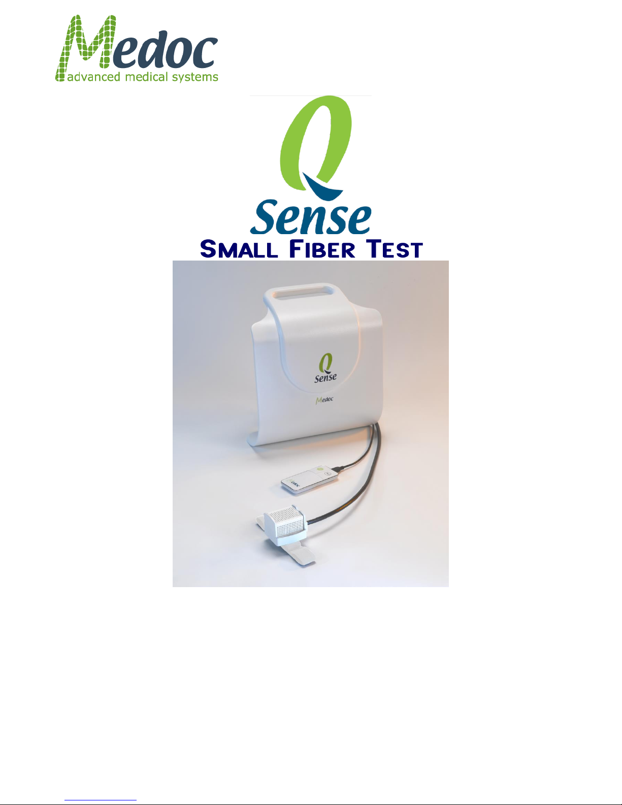
Service Reference Manual
Page 2
Pathway Technical Reference Service Manual Table of Contents
Proprietary 2 of 44
This Service Manual contains proprietary information of Medoc Ltd. and may not be reproduced in
any form without prior written consent from Medoc Ltd.
Q-Sense Technical Reference Service Manual 6th Edition, March 2018
Medoc Ltd.
1 Ha-Dekel St., PO Box 423 Ramat Yishai 3009500, ISRAEL
Tel: +972-4-9038800 / Fax: +972-4-9038808
E-Mail [email protected]
Medoc U.S.A
Compass Medical Technologies, Inc.
1502 West Highway 54 - Suite 404
Durham, North Carolina, 27707, U.S.A
Tel: +1-(919) 402-9600 / Fax: +1-(919) 402-9607
E-Mail: [email protected]
European Authorized Representative
CEpartner4U BV
Esdoornlaan 13 3951 DB Maarn, The Netherlands
Phone: +31 343 442.524 / Fax: +31 343 442 162
Mobile: +31 6 516 536.26
E-Mail: [email protected]
0473
This device complies with 93/42/EEC MDD
Page 3

Pathway Technical Reference Service Manual Table of Contents
Proprietary 3 of 44
Table of Contents
1 Safety Guidelines and Regulations ........................................................................... 6
1.1 User Manual Icons .......................................................................................................... 6
1.2 Intended use ................................................................................................................... 7
1.3 Safety and Regulatory Summary ................................................................................... 7
1.4 Safety Requirements ...................................................................................................... 7
1.4.1 Warnings .................................................................................................................................... 7
1.4.2 Cautions ..................................................................................................................................... 8
1.4.3 Equipment Classification ........................................................................................................... 8
1.5 System Protection .......................................................................................................... 9
1.5.1 System Self-Test ....................................................................................................................... 9
1.5.2 Temperature Safety Mechanisms .............................................................................................. 9
1.5.3 Thermode Detection .................................................................................................................. 9
1.6 Equipment Labels, Symbols, Warning Statements and Abbreviations .................... 10
1.7 Electromagnetic immunity ........................................................................................... 12
1.8 Recommended Separation Distance between Portable and Mobile RF
Communications Equipment and Q-Sense ........................................................................... 14
1.9 Technical Data .............................................................................................................. 15
2 Thermode Management ............................................................................................ 17
2.1 Enable/Disable Current Thermode .............................................................................. 17
2.2 Thermode File Management ......................................................................................... 18
2.2.1 List of Available Thermode File Options .................................................................................. 18
2.2.2 View Thermode List ................................................................................................................. 19
2.2.3 Create a New Thermode File .................................................................................................. 19
2.2.4 Delete a Thermode File ........................................................................................................... 20
2.2.5 Export a Thermode File ........................................................................................................... 20
2.2.6 Import a Thermode File ........................................................................................................... 20
2.2.7 Change the Thermode File Currently in Use ........................................................................... 21
2.2.8 Load Properties from Thermode Currently Used by the System............................................. 21
2.3 Thermode Properties .................................................................................................... 22
2.3.1 General .................................................................................................................................... 22
2.3.2 TEC1 / TEC2 ........................................................................................................................... 22
3 Thermode Calibration ............................................................................................... 24
3.1 Thermode Calibration Overview .................................................................................. 24
3.2 Calibration Kit ............................................................................................................... 24
3.3 Calibration Kit Setup .................................................................................................... 25
3.4 Automatic Calibration ................................................................................................... 27
3.4.1 Thermometer Communication Setup ....................................................................................... 27
3.4.2 Automatic Calibration Procedure ............................................................................................. 28
3.4.3 Concluding Steps ..................................................................................................................... 31
3.4.4 Automatic Calibration Properties ............................................................................................. 31
3.5 Manual Calibration ........................................................................................................ 33
3.5.1 Manual Calibration Procedure ................................................................................................. 33
3.5.2 Concluding Steps ..................................................................................................................... 35
3.5.3 Manual Calibration properties .................................................................................................. 35
3.5.4 Saving calibration tables and back-up: .................................................................................... 35
3.5.5 Error and Warning messages .................................................................................................. 36
Page 4

Pathway Technical Reference Service Manual Table of Contents
Proprietary 4 of 44
4 Q-SENSE Firmware ................................................................................................... 37
4.1 Preparing the System for Firmware Update ................................................................ 37
4.2 Firmware Update ........................................................................................................... 39
4.3 Firmware and License Update ..................................................................................... 42
5 Appendix A – RS232-USB Adaptor Driver ............................................................... 44
Page 5

Pathway Technical Reference Service Manual List of Figures
Proprietary 5 of 44
List of Figures
Figure 1: Q-Sense Label ............................................................................................................... 10
Figure 2: Hardware Settings Menu ................................................................................................ 17
Figure 3: Hardware Settings – Thermode tab................................................................................ 19
Figure 4: Thermode Properties ..................................................................................................... 22
Figure 5: Thermode Properties – LUT ........................................................................................... 23
Figure 6: Calibration Kit ................................................................................................................ 25
Figure 7: Thermode adaptor ......................................................................................................... 25
Figure 8: Thermode adaptor over mechanical body ...................................................................... 25
Figure 9: Screw the thermode adaptor to the mechanical body ..................................................... 25
Figure 10: Applying Thermal Grease ............................................................................................ 26
Figure 11: Secure Thermode on jig 1 ............................................................................................ 26
Figure 12: Secure Thermode on jig 2 ............................................................................................ 26
Figure 13: Secure Thermode on jig 3 ............................................................................................ 26
Figure 14: Hang the thermode and jig on the Q-Sense ................................................................. 26
Figure 15: Thermometer D-type Connector ................................................................................... 27
Figure 16: Thermometer Communication Connection ................................................................... 27
Figure 17: RS232-to-USB Adapter Connection ............................................................................. 28
Figure 18: USB cable connection ................................ .................................................................. 28
Figure 19: Calibration port selection .............................................................................................. 29
Figure 20: Hardware Settings Menu .............................................................................................. 29
Figure 21: Thermode Calibration – Thermode ............................................................................... 30
Figure 22: Thermode Automatic Calibration .................................................................................. 30
Figure 23: Automatic Calibration Progress .................................................................................... 31
Figure 24: Automatic Calibration tab ............................................................................................. 32
Figure 25: Automatic Calibration Properties tab ............................................................................ 32
Figure 26: Hardware Settings Menu .............................................................................................. 33
Figure 27: Thermode Calibration – General .................................................................................. 33
Figure 28: Thermode Calibration – Manual Calibration tab ........................................................... 34
Figure 29: Back of the Q-Sense cover .......................................................................................... 37
Figure 30: Opening Q-Sense ........................................................................................................ 38
Figure 31: JTAG Port Location ...................................................................................................... 38
Figure 32: JTAG USB Port connected .......................................................................................... 38
Figure 33: JTAG Firmware Update ............................................................................................... 39
Figure 34: Choose Image.............................................................................................................. 39
Figure 35: Closing Q-Sense .......................................................................................................... 40
Figure 36: Internal pins ................................................................................................................. 40
Figure 37: Communication USB port ............................................................................................. 40
Figure 38: JTAG Firmware Update ............................................................................................... 42
Figure 39: Firmware & License Update ......................................................................................... 42
Figure 40: RS232-USB driver installation notification .................................................................... 44
Page 6
Pathway Technical Reference Service Manual
Proprietary 6 of 44
Disclaimer
Medoc assumes no liability for use of this document if any unauthorized changes to the content
or format have been made. Every care has been taken to ensure the accuracy of the
information in this document. However, Medoc assumes no responsibility or liability for errors,
inaccuracies, or omissions that may appear in this document. Medoc reserves the right to
change the product without further notice to improve reliability, function or design. This manual
is provided without warranty of any kind, implied or expressed, including, but not limited to, the
implied warranties of merchantability and fitness for a particular purpose.
1 Safety Guidelines and Regulations
This manual is written for trained users of Medoc Products. The user includes the body with
authority over the equipment and those persons who actually handle the equipment.
Before attempting to work with this equipment, read, understand, note and strictly observe all
Warning notices, Cautions and Safety markings on the equipment.
Before attempting to work with this equipment, make sure that this manual and any Release
Notes delivered with the software media pack have been thoroughly read and fully understood,
paying particular attention to all:
1. Warnings
2. Cautions
3. Notes
4. Important Notices
5. User Notices
1.1 User Manual Icons
The following icons are used throughout the user manual:
Warning: A condition that could cause serious injury or death to a
patient and/or operator if instructions are not followed.
Caution: A condition that could cause possible damage to equipment or
cause the system to function inaccurately.
Note: Indicates important user information regarding the use of the
system.
Advice: Refer to instruction manual/ booklet
INSTRUCTION: Indicates an instruction where it is important to follow
the user manual literally as described.
Page 7
Pathway Technical Reference Service Manual
Proprietary 7 of 44
1.2 Intended use
The use of the Q-sense system should be as intended by Medoc Ltd. and as specified in the user
manual. The Q-Sense is a pain management and pain research system intended to be used for
the quantitative assessment of small nerve fiber dysfunctions. It measures sensory thresholds
such as cold and warm sensation and heat-induced pain.
1.3 Safety and Regulatory Summary
Read and follow all WARNINGS, CAUTIONS and NOTES provided in this manual. To avoid the
possibility of injury, damage to your system, or loss of data, always follow these precautions during
system operation.
The Q-SENSE system complies with safety requirements for medical electrical systems (based
on the IEC 60601-1 standard).
The Q-SENSE system complies with electromagnetic emission levels (based on table 201 in
the IEC 60601-1-2 standard).
The Q-SENSE system complies with electromagnetic immunity levels (based on tables 202
and 204 in the IEC 60601-1-2 standard).
This device complies with 93/42/EEC MDD.
It is recommend keeping a distance of 3 meters between portable and mobile RF
communications equipment and the Q-SENSE (based on table 206 in the IEC 60601-1-2
standard).
1.4 Safety Requirements
The Q-SENSE system can be tested according to IEC 62353 Recurrent test
and test after repair of medical electrical equipment.
Do not modify or replace any component of the Q-SENSE system.
Do not use any other power supply other than the one provided by the
manufacturer.
Connecting or replacing external Q-SENSE accessories is allowed.
Keep all liquids away from the Q-SENSE system.
Unplug the Q-SENSE system if it is not to be used for a long period of time.
Do not block airflow anywhere around the Q-SENSE system.
1.4.1 Warnings
Only personnel properly trained to operate the Q-SENSE system should use this system.
Do not turn on system power until all cables have been properly connected and verified.
Do not use any electrode paste, gel, or other material on the contact point between the
Thermode plate and the skin of the tested subject.
To reduce the risk of injury, attach the Thermode to the subject only prior to running a test
while MEDOC Main Station is in Test screen. Remove the Thermode from the subject skin
before leaving the Test Screen.
Page 8

Pathway Technical Reference Service Manual
Proprietary 8 of 44
Connect the Thermode to the patient's skin ONLY during the test; not during system Self-Test,
programming or maintenance.
The computer that is used to operate the Q-SENSE system must be powered through a
Medical Grade Isolation Transformer only.
The use of accessories or cables other than those specified, with the exception of accessories
or cables sold by the manufacturer as replacement parts, may result in increased emissions or
decreased electrical immunity of the device.
Connecting any device or accessory that has no medical grade certificate to the Q-SENSE
system is not allowed.
Using a Thermode without the appropriate calibration table may result in potential harm or
injury.
Using the Q-SENSE system not according to instructions may result in potential harm or injury.
Adverse Reaction: Skin irritation (in addition to pain sensation) beneath the probes has been
reported with the use of a stimulator, which was based on similar technology as the Q-Sense
device.
Be aware of potential risk of skin damage caused by wrong parameter combination.
1.4.2 Cautions
Proper use of this device depends on careful reading of all instructions and labels.
Turn OFF system power before connecting or disconnecting any system component(s) or
accessories. Otherwise, you may damage the device(s).
The Thermode is very delicate and can easily be damaged. Therefore, handle with care.
If you disconnect any cables, take care to reconnect them correctly to prevent damage to the
system or components.
This equipment uses a three-wire power cord with a hospital grade plug (for non-USA
applications, the IEC 60601-1-approved plug).
Inspect the power cord often for fraying or other damage. DO NOT operate the apparatus if the
power cord or plug is damaged.
The computer that is used to operate the Q-SENSE system must never be connected to a
network while it is used for running tests.
The Q-SENSE system does not require special precautions regarding EMC, and needs to be
installed and put into service according to this manual.
Portable and mobile RF communications equipment can affect medical electrical equipment.
Use caution when using the Q-SENSE Thermode on patients with suspected neuropathies as
they may be more susceptible to soft tissue or nerve damage at extreme temperatures. Also,
patients with neuropathies may not be able to properly discontinue use of the device during
prolonged hot or cold stimulation.
1.4.3 Equipment Classification
Degree of protection against electric shock: Class I
Type of protection against electric shock: BF
Type of Operation: Continuous
Protection against ingress of liquids: Not protected against ingress of liquids
Ordinary equipment.
Computer must comply with IEC 950 - EN 60950 - UL 60950.
Page 9

Pathway Technical Reference Service Manual
Proprietary 9 of 44
1.5 System Protection
1.5.1 System Self-Test
Upon start-up the system performs a self-test in which system sensors are being tested. If a
malfunction is detected, an appropriate message is displayed and the system cannot operate until
that malfunction is resolved.
1.5.2 Temperature Safety Mechanisms
Several safeguard mechanisms have been implemented in the system to safeguard against
extreme temperatures and to protect the tested subject and the unit.
Software protection mechanisms include:
Temperature upper and lower limits – In normal operation, Thermode temperature will always
be within these limits.
Time duration limits – Thermode temperature is limited in duration. If the Thermode
temperature maintains a specific temperature (or above) for a longer period of time then
specified for that temperature, the system will go into Safe Mode.
Safe Mode – a protective state of the system in which it is not possible to run tests. In any case
of suspected malfunction or if any modification is made to system hardware settings, system
will remain in safe mode until a system Self-Test is performed.
Hardware protection mechanisms include:
If the Thermode temperature reaches 57C an analog circuit overrides the system and lowers
the temperature gradually.
1.5.3 Thermode Detection
The system automatically detects that a Thermode is missing, and disables it in order to protect
both system and user.
Page 10
Pathway Technical Reference Service Manual
Proprietary 10 of 44
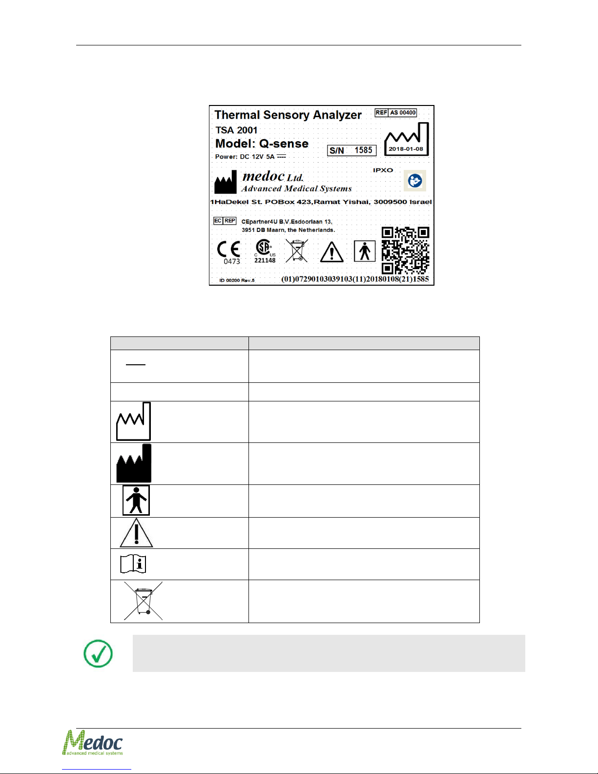
1.6 Equipment Labels, Symbols, Warning Statements and
Abbreviations
Figure 1: Q-Sense Label
Table 1: Equipment Labels
Equipment Label
Description
I
O
Power switch ON/OFF
COM
Communications connector.
Date of Manufacture (YYYY-MM)
Manufacturer
Degree of protection against electric shock –
Applied Part Type BF.
Warning - Connect the power cord to the power
outlet, according to the local electrical standards.
Refer to Manual
Disposal according to electronic scrap ordinance
Manual edition refers to current version of manufactured system
Page 11

Pathway Technical Reference Service Manual
Proprietary 11 of 44
Medoc reserves the right to change specifications without prior notice, in line
with the company policy of constant product improvement
Page 12

Pathway Technical Reference Service Manual
Proprietary 12 of 44
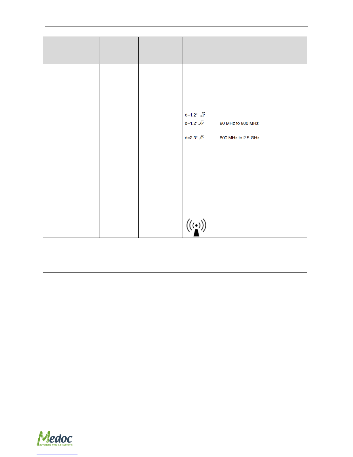
1.7 Electromagnetic immunity
The Q-Sense is intended for use in the electromagnetic environment specified below. The
customer or the user of the Q-Sense should assure that it is used in such an environment.
Immunity test
IEC 60601
test level
Compliance level
Electromagnetic environment –
guidance
Electrostatic
discharge (ESD)
IEC 61000-4-2
±6 kV contact
±8 kV air
±6 kV contact
±8 kV air
Floors should be wood, concrete
or ceramic tile. If floors are
covered with synthetic material,
the relative humidity should be at
least 30 %.
Power frequency
(50/60 Hz)
magnetic field
IEC 61000-4-4
3 A/m
50 & 60 Hz
3 A/m
50 & 60 Hz
Power frequency magnetic fields
should be at levels characteristic
of a typical location in a typical
commercial or hospital
environment.
Electrical fast
transient/burst
IEC 61000-4-4
±2 kV for power
supply lines
±2 kV for power
supply lines
Mains power quality should be
that of a typical commercial or
hospital environment.
Surge
IEC 61000-4-5
±1 kV line(s) and
neutral
±1 kV line(s) and
neutral
Mains power quality should be
that of a typical commercial or
hospital environment.
Voltage dips, short
interruptions and
voltage variations
on power supply
input lines
IEC 61000-4-11
<5 % UT
(>95 % dip in UT)
for 0,5 cycle
40 % UT
(60 % dip in UT)
for 5 cycles
70 % UT
(30 % dip in UT)
for 25 cycles
<5 % UT
(>95 % dip in UT)
for 5s
<5 % UT
(>95 % dip in UT)
for 0,5 cycle
40 % UT
(60 % dip in UT)
for 5 cycles
70 % UT
(30 % dip in UT)
for 25 cycles)
<5 % UT
(>95 % dip in UT)
for 5s
Mains power quality should be
that of a typical commercial or
hospital environment. If a dip or
an interruption of mains power
occurs, the current of the Qsense may be dropped off from
normal level, it may be necessary
to use uninterruptible power
supply or a battery.
NOTE UT is the a.c. mains voltage prior to application of the test level
Page 13
Pathway Technical Reference Service Manual
Proprietary 13 of 44
Immunity test
IEC 60601
test level
Compliance
level
Electromagnetic environment – guidance
Radiated RF
IEC 61000-4-3
3 V/m
80 MHz to
2.5 GHz
3 V/m
Portable and mobile RF communications
equipment should be used no closer to any
part of the Q-Sense, including cables, than
the recommended separation distance
calculated from the equation applicable to
the frequency of the transmitter.
Recommended separation distance
where P is the maximum output power rating
of the transmitter in watts (W) according to
the transmitter manufacturer and d is the
recommended separation distance in metres
(m).
Field strengths from fixed RF transmitters,
as determined by an electromagnetic site
survey* should be less than the compliance
level in each frequency range**
Interference may occur in the vicinity of
equipment marked with the following symbol:
NOTE 1 At 80 MHz and 800 MHz, the higher frequency range applies.
NOTE 2 These guidelines may not apply in all situations. Electromagnetic propagation is affected by
absorption and reflection from structures, objects and people.
* Field strengths from fixed transmitters, such as base stations for radio (cellular/cordless)
telephones and land mobile radios, amateur radio, AM and FM radio broadcast and TV broadcast cannot
be predicted theoretically with accuracy. To assess the electromagnetic environment due to fixed RF
transmitters, an electromagnetic site survey should be considered. If the measured field strength in the
location in which the Q-Sense is used exceeds the applicable RF compliance level above, the Q-Sense
should be observed to verify normal operation. If abnormal performance is observed, additional measures
may be necessary, such as reorienting or relocating the Q-Sense.
** Over the frequency range 150 kHz to 80 MHz, field strengths should be less than 3 V/m.
Page 14
Pathway Technical Reference Service Manual
Proprietary 14 of 44
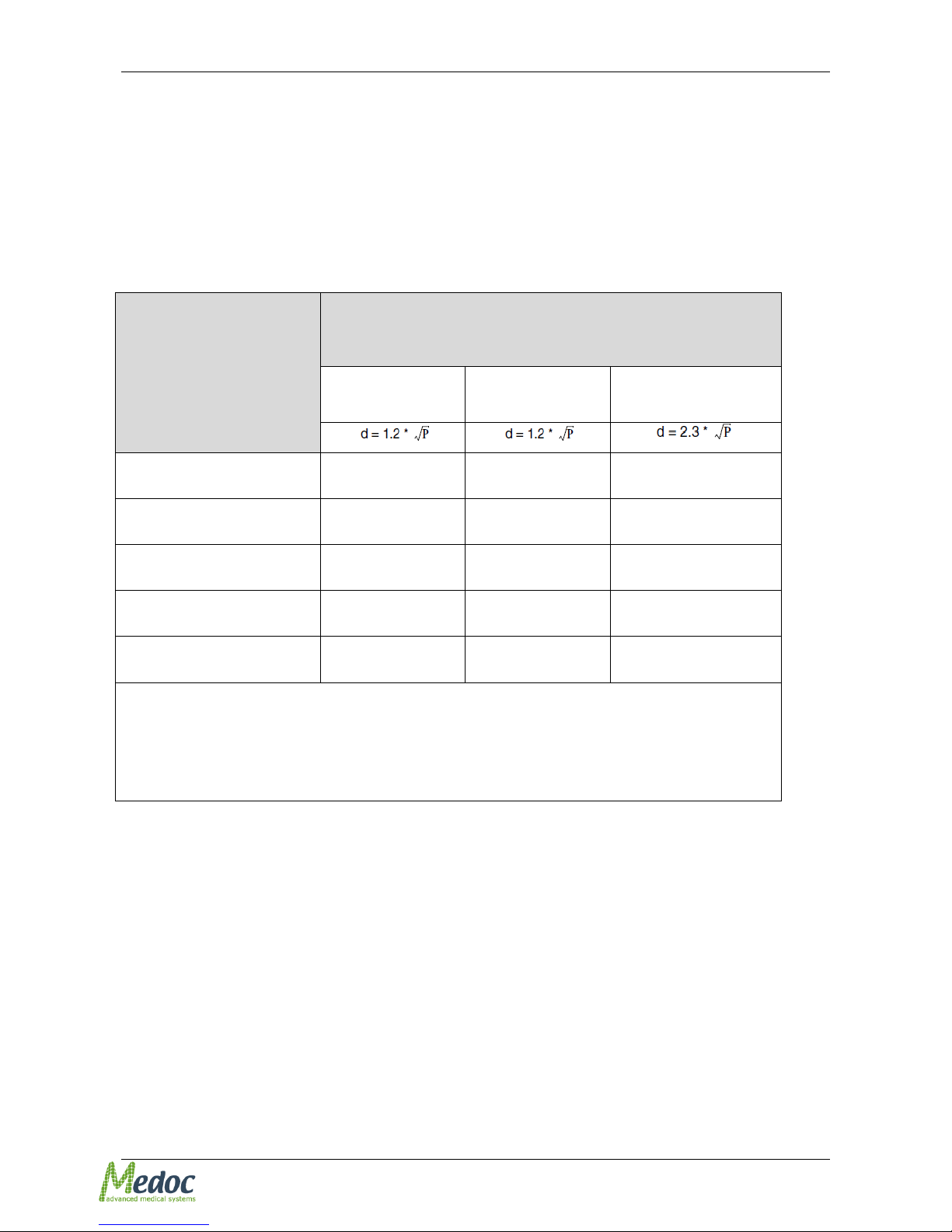
1.8 Recommended Separation Distance between Portable and Mobile
RF Communications Equipment and Q-Sense
The Q-Sense is intended for use in an electromagnetic environment in which radiated RF
disturbances are controlled. The customer or the user of the Q-Sense can help prevent
electromagnetic interference by maintaining a minimum distance between portable and mobile RF
communications equipment (transmitters) and the Q-Sense as recommended below, according to
the maximum output power of the communications equipment.
Rated maximum output
power of transmitter
(W)
Separation distance according to frequency of transmitter
(m)
150 kHz to 80
MHz
80 MHz to 800
MHz
80 MHz to 2.5 GHz
0.01
0.12
0.12
0.23
0.1
0.37
0.37
0.74
1
1.2
1.2
2.3
10
3.7
3.7
7.4
100
12
12
23
For transmitters rated at a maximum output power not listed above, the recommended separation
distance d in metres (m) can be estimated using the equation applicable to the frequency of the
transmitter, where P is the maximum output power rating of the transmitter in watts (W) according to
the transmitter manufacturer.
NOTE 1: At 80 MHz and 800 MHz, the separation distance for the higher frequency range applies.
NOTE 2: These guidelines may not apply in all situations. Electromagnetic propagation is affected
by absorption and reflection from structures, objects and people.
Page 15
Pathway Technical Reference Service Manual
Proprietary 15 of 44
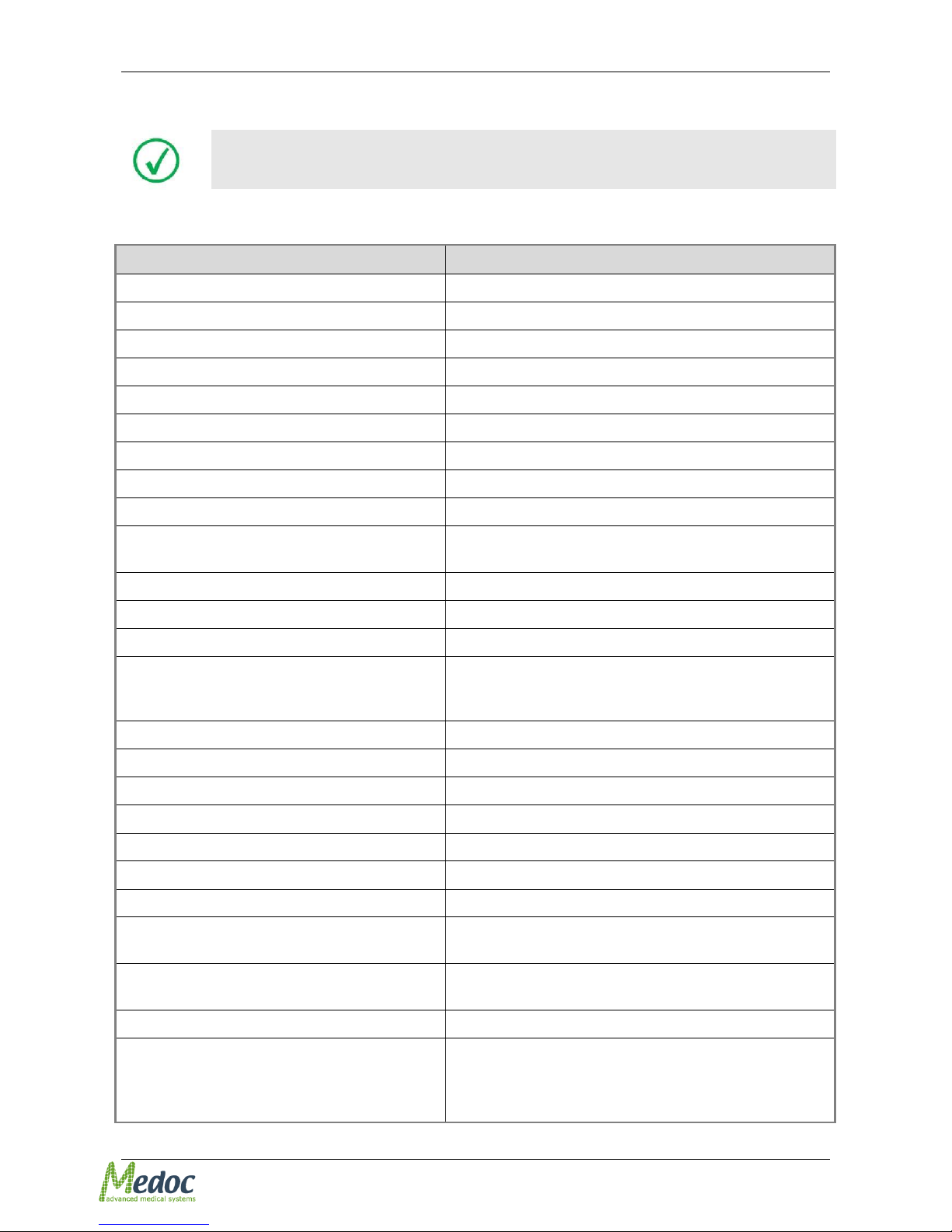
1.9 Technical Data
Medoc reserves the right to change specifications without prior notice, in line
with the company policy of constant product improvement
The table below describes the technical specifications and capabilities of the Q-Sense system.
Table 2: Q-SENSE Specifications
Parameter
Specification
Thermode Active Area
30x30 mm
Temperature Range
16– 50 °C
Heating Rate
0 – 2 °C/Sec ± 10%
Cooling Rate
0 - 1 °C/Sec ± 10%
Stimulation Methods
Limits, Levels & TSL
Set-Point Resolution
0.1 °C
Display Resolution
0.1 °C
Repeatability
± 0.3 °C
Absolute Accuracy
±0.3 °C
Operating Mode
Intervals*
*(Short pause between patients may be required)
Minimum Inter Stimuli Interval (ISI)
2 sec
Maximum Consecutive Stimuli
10
Baseline Temperature Range
28 – 40 °C
Programmable Parameters
Method, Adaptation Temperature, Heating Rate,
Cooling Rate, Number of Stimuli, ISI, Sound Option,
Randomize Option
Communication with PC
USB
Communication with Printer
Via PC
Standards
IEC 60601-1; IEC 60601-1-2
Approvals
CE, FDA
Operating Voltage
12 VDC, 5A
Power Supply
100 – 240 VAC, 4 – 2 A, 50/60 Hz
Power Consumption
Approx. 60W
Dimensions
31cm X 28 cm X 16cm (table or wall mount)
Shipping: 53cm X 34cm X 22cm
Weight
Approx. 8 Kg
Shipping: Approx. 10 Kg
Software
Propriety Software Application (Included)
Computer Requirements (PC not included)
Notebook PC (Atom CPU not supported)
At least 2 GB RAM, 6 GB Free disc space.
Windows 7/8 (32 & 64 bit) , Windows XP (32bit) sp.
3 and above
Page 16

Pathway Technical Reference Service Manual
Proprietary 16 of 44
Parameter
Specification
Screen Resolution
1366X768 and higher
Patient Response Unit
2 buttons (Yes / No) Response Unit
Product life time
10 years
Page 17

Pathway Technical Reference Service Manual
Proprietary 17 of 44
2 Thermode Management
Medoc Main Station software enables you to create and manage your Thermode database. This
section explains how to create a new Thermode file, load from existing file, edit, save and delete
files.
2.1 Enable/Disable Current Thermode
Enabling or disabling the current Thermode controls whether or not the Thermode will be activated.
If the Thermode is disabled, it can't be controlled by the system. The Thermode may be
automatically disabled if the Thermode is accidently disconnected or due to malfunction.
1. Turn ON the Q-SENSE system. Make sure that communication is established.
2. From the Settings menu, select Hardware Settings. Open the General tab
3. The following screen is displayed:
Figure 2: Hardware Settings Menu
4. Check the Thermode Enabled box at the top left side of the screen to Enable the Thermode
5. Click Apply
The Thermode needs to be enabled in order to manage the Thermode
database.
Page 18
Pathway Technical Reference Service Manual
Proprietary 18 of 44
2.2 Thermode File Management
Using the correct Thermode parameters is critical to ensure the safe and reliable use of the QSense Thermode. The Thermode properties are stored in Thermode files which are saved in the
Medoc Main Station database. The Thermode properties currently in use by the Q-Sense system
are also saved on the Q-Sense system memory.
The Thermode file contains of all Thermode data, including calibration tables
for all it temperature sensors and properties important for accurate
temperature control.
This section covers the all tasks related Thermode file database management.
For Thermode Calibration Procedure, refer to section 3, page 24
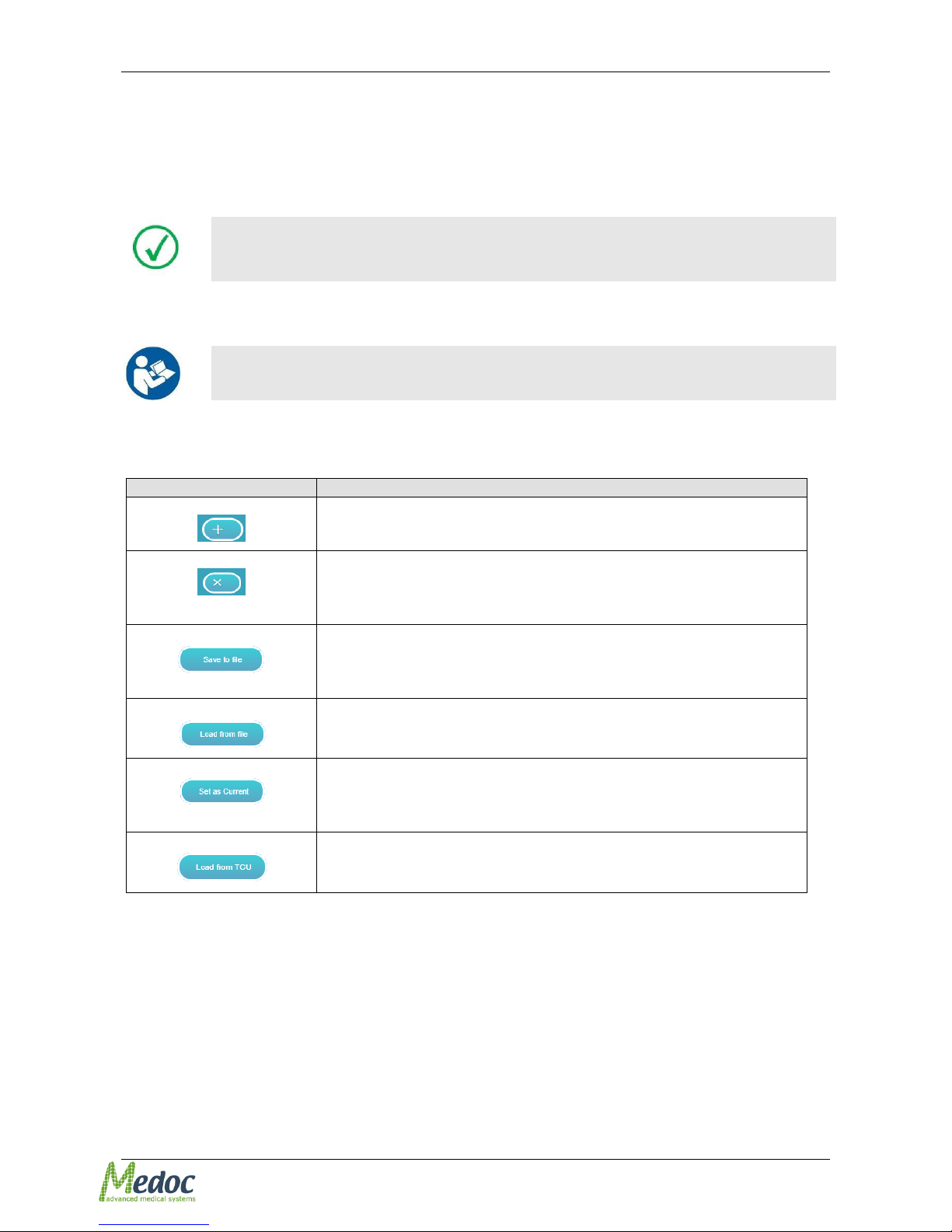
2.2.1 List of Available Thermode File Options
Table 3: List of Thermode File Options
Description
Create a New Thermode file in database. See section 2.2.3
Delete a Thermode file from the database. See section 2.2.4
It is not possible to delete a Thermode, when it is the only one in
the list.
Export a Thermode file from the database. See section 2.2.5
Medoc recommends using an identifiable name when saving the
Thermode file.
Import a Thermode file into the database. See section 2.2.6
Change the Thermode parameters currently used by the system.
See section 2.2.7
Load Thermode data from system into a database Thermode file.
See section 2.2.8
Page 19
Pathway Technical Reference Service Manual
Proprietary 19 of 44
2.2.2 View Thermode List
1. Turn ON the Q-SENSE system, and make sure that communication is established.
2. From the Settings menu, select Hardware Settings. Open the Thermode tab.
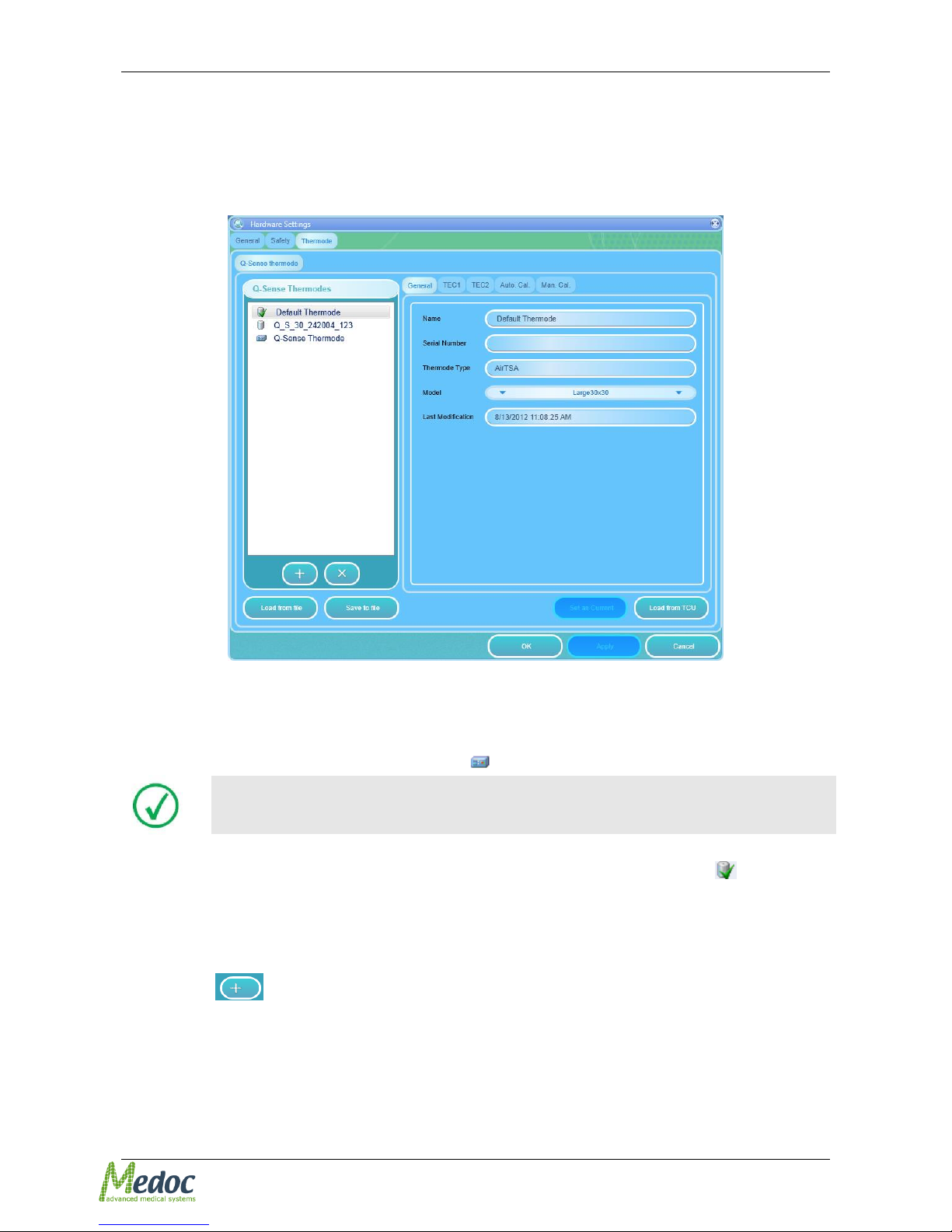
3. The following screen is displayed:
Figure 3: Hardware Settings – Thermode tab
4. The Thermode list on the left side panel contains a list of all Thermodes currently listed in the
database.
5. The last Thermode in the list is the Thermode file currently used in the Q-Sense device. This
Thermode is indicated by the following icon:
Only the Thermodes listed in the database can be edited. The Q-Sense
Thermode is for viewing only and shows the file currently used by the system.
6. A copy of the Thermode files used by the system should exist in the database and is indicated
The Thermode currently in use by the system is indicated by the following icon:
2.2.3 Create a New Thermode File
To create a new Thermode file in the database:
1. Open the Thermode tab in Hardware Settings (see section 2.2.2)
1. Click the button.
2. In the general tab enter Thermode details: Name (required) and Serial Number.
3. Click Apply.
4. Calibrate the new Thermode (see section 3, page 24)
Page 20
Pathway Technical Reference Service Manual
Proprietary 20 of 44
2.2.4 Delete a Thermode File
Delete Thermode files which are no longer relevant (for example if the Thermode is out of use or
has been replaced)
To delete a Thermode file from the database:
1. Open the Thermode tab in Hardware Settings (see section 2.2.2)
2. From the Thermode list in the left panel select the Thermode file to be deleted.
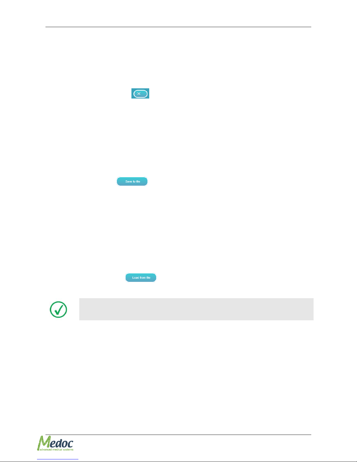
3. Click the Delete Thermode button
4. Click Yes to confirm.
2.2.5 Export a Thermode File
Export your Thermode files and save them for backup purposes. Thermode files are exported as a
.Thr file and can only be opened using Medoc Main Station software.
To export a Thermode file from the database:
1. Open the Thermode tab in Hardware Settings (see section 2.2.2)
2. From the Thermode list in the left panel select the Thermode file to be exported.
3. Click the Save to file button
4. Select the location where you want to save the Thermode file.
5. Type a meaningful name (Thermode type, serial number) and click the Save button.
2.2.6 Import a Thermode File
Import your Thermode files into the database when re-installing Medoc Main Station software or
restoring from backup. Thermode files are identified by a .Thr suffix and can only be opened using
Medoc Main Station software.
To Import a Thermode file into the database:
1. Open the Thermode tab in Hardware Settings (see section 2.2.2)
2. Click the Load from file button
3. Select the Thermode file to import and Click the Open button.
After initial Thermode installation, load the applicable Thermode calibration
tables from the Installation CD.
Page 21
Pathway Technical Reference Service Manual
Proprietary 21 of 44
2.2.7 Change the Thermode File Currently in Use
When switching Thermodes, or calibrating, you might want to change the Thermode file which is
currently used by the system.
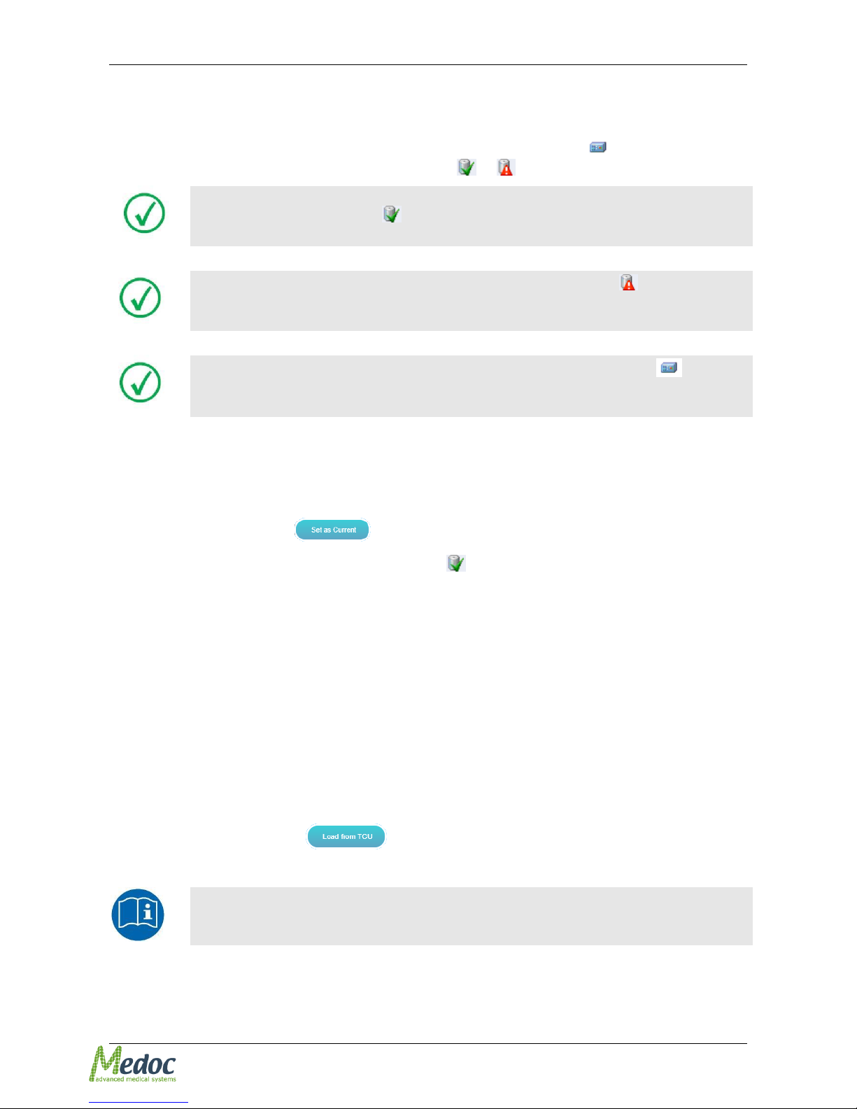
The Thermode currently in use by the system can be identified by the icon . The corresponding
Thermode file in the database is identified by the icon or .
The database Thermode file corresponding to the Thermode file used by the
system is identified by the icon. This symbol indicates that the Thermode
parameters in the database file match those used by the system.
If the database Thermode has the red exclamation mark on it , the
parameters don’t match those currently used by the system and may indicate
malfunction or that Thermode parameters have been changed.
Only the parameters that are displayed under Q-SENSE Thermode in the
Thermode list are saved on the System memory. The other Thermodes on the
list are stored only in Medoc Main Station database.
To set a database Thermode file as the one currently in use:
1. Open the Thermode tab in Hardware Settings (see section 2.2.2)
2. From the Thermode list in the left panel select the Thermode file to be set as current.
3. Click the Set as current button
4. The selected Thermode file should now have an icon on it.
5. In the Thermode list on the left side of the screen, select the Thermode you wish to use.
6. Click the Set as current button.
2.2.8 Load Properties from Thermode Currently Used by the System
Load properties currently stored in system memory into a new database Thermode file. This may
be needed when re-installing Medoc Main Station and no backup files for the Thermode exist.
To load Thermode parameters from the System:
1. Open the Thermode tab in Hardware Settings (see section 2.2.2)
2. Create a new Thermode file (see section 2.2.3) or select a Thermode file from list into which
you want to load Thermode parameters.
3. Click the Load from TCU button.
Medoc recommends that you manage a backup folder for all your Thermode
files, so that in case of damaged database, the calibration tables and other
Thermode parameters would not be lost!
Page 22
Pathway Technical Reference Service Manual
Proprietary 22 of 44
2.3 Thermode Properties
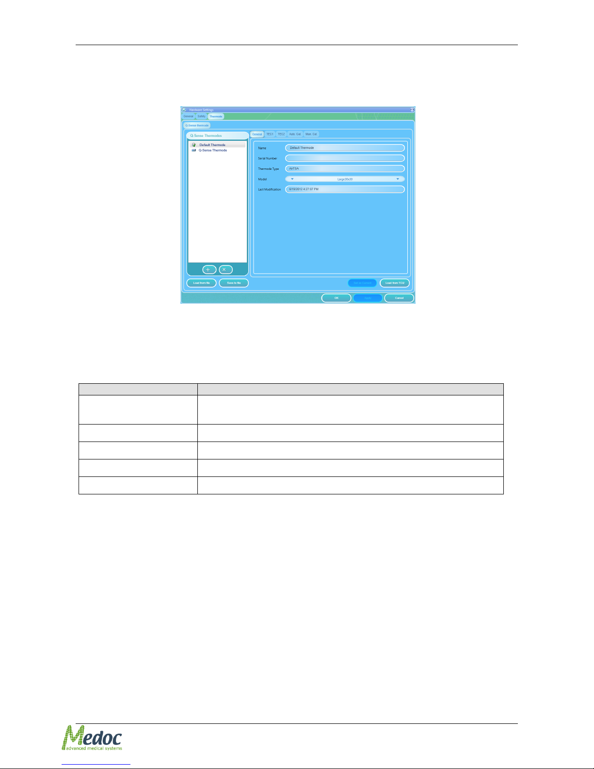
Thermode properties can be viewed from the Thermode tab in Hardware settings.
Figure 4: Thermode Properties
2.3.1 General
The General tab displays the Thermode identification details.
Table 4: Thermode Identification Details
Description
Name
The Thermode name, according to user selection. It is advisable to
use meaningful names.
Serial Number
The Thermode serial number.
Thermode Type
The selected Thermode type (Q-sense).
Model
The Thermode model, according to selection.
Last Modification
The date when the Thermode properties were last updated.
2.3.2 TEC1 / TEC2
The TEC1 and TEC 2 are the calibration tables for the temperature sensors (thermistors) used in
the Thermode.
Page 23

Pathway Technical Reference Service Manual
Proprietary 23 of 44
Figure 5: Thermode Properties – LUT
Page 24
Pathway Technical Reference Service Manual
Proprietary 24 of 44
3 Thermode Calibration
Thermode calibration is specific to Thermode and System. Therefore calibration tables can’t be
shared between Thermode and/or Q-Sense systems. Calibration must be performed for each
Thermode and System separately.
The calibration procedure must be performed using the Calibration kit supplied by Medoc and
Medoc Main Station software.
Calibration may only be performed by a trained person, and only by using
the Thermal Calibration Kit supplied by Medoc.
3.1 Thermode Calibration Overview
Thermode Calibration refers to the process of assigning a temperature with the digital input
received from the temperature sensors.
Calibration table consist of 30 temperature points. During calibration each temperature point is
assigned two ADC values referring to the calibrated measures according to Thermode type. All
values (ADC and temperatures) can be monotonically increasing only.
The calibrated measures in Q-sense Thermodes are two thermistors. Their ADC values are
referred to as TEC 1 and TEC 2.
Table 5: Complete calibration range
Thermode Type
License
Calibration range
Q-sense
Standard 16˚C - 50˚C
10˚C - 60˚C
For more information regarding calibration procedure please refer to:
Automatic calibration (section 3.4 , page 27 )
Manual calibration (section 3.5, page 33 )
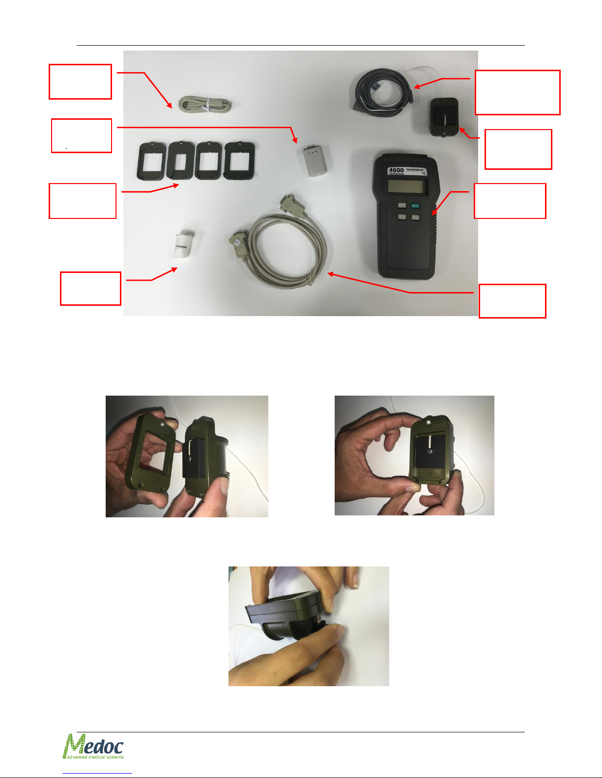
3.2 Calibration Kit
Thermal Calibration kit (AS00406):
Case
YSI Precision Thermometer, model 4600.
YSI Probe 4.8 mm diameter sensor, model 427
Thermal grease.
Calibration certificate of YSI Thermometer from the manufacture.
Mechanical jig body
Mechanical Thermode adaptor / mask
Thermode adaptor screw
Communication cables
Page 25
Pathway Technical Reference Service Manual
Proprietary 25 of 44
Figure 6: Calibration Kit
3.3 Calibration Kit Setup
1. Place the Thermode adaptor over the mechanical jig body (see Figure 7, Figure 8)
Figure 7: Thermode adaptor
Figure 8: Thermode adaptor over mechanical
body
2. Tight the thermode adaptor to the mechanical body using the screw (see Figure 9)
Figure 9: Screw the thermode adaptor to the mechanical body
Thermode
adaptors
YSI probe 4.8 mm
Sensor 427
USB Cable
Mechanical
jig body
Digital
Thermometer
Thermal
Grease
RS232 Cable
RS232
USB
Page 26
Pathway Technical Reference Service Manual
Proprietary 26 of 44
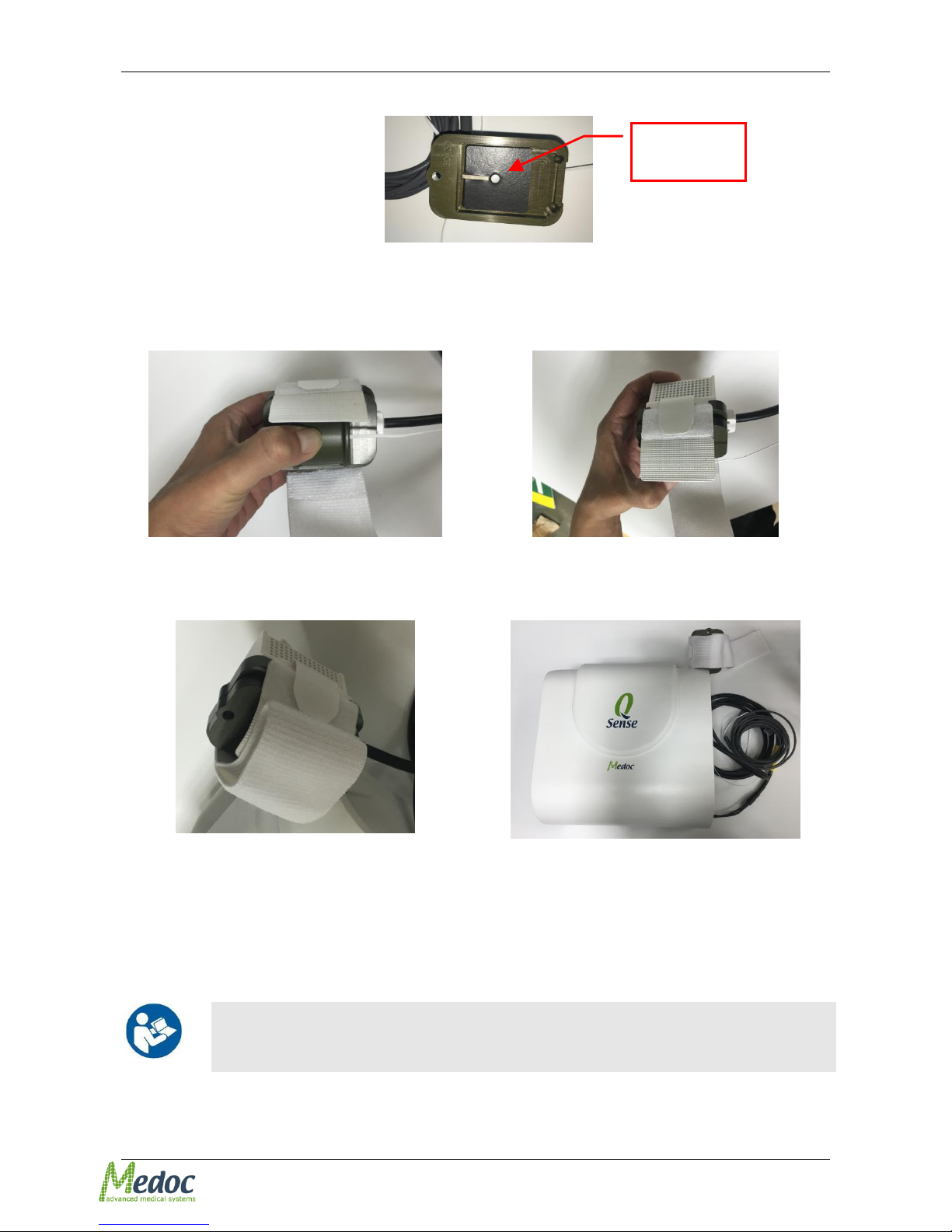
3. Apply Thermal grease (from the thermal calibration kit) to the Thermal sensor. See Figure 10.
Figure 10: Applying Thermal Grease
4. Connect the connector of the Thermal sensor to the Thermometer
5. Place the Thermode in the adaptor and secure with the strap (see Figure 11, Figure 12, Figure
13)
Figure 11: Secure Thermode on jig 1
Figure 12: Secure Thermode on jig 2
Figure 13: Secure Thermode on jig 3
Figure 14: Hang the thermode and jig on the
Q-Sense
6. Place the Thermode with the mechanical jig body on the Q-Sense device, see Figure 14
7. Turn ON the Thermometer, by pressing the ON button
8. Turn ON the Q-SENSE system, and advance to preferred calibration procedure
There are two options to continue the calibration procedure: Automatic
(section 3.4, page 27) or Manual (section 3.5, page 33) calibration. Follow
the instructions according to desired method.
Apply Thermal
grease here
Page 27
Pathway Technical Reference Service Manual
Proprietary 27 of 44
3.4 Automatic Calibration
Medoc highly recommends carefully reading the entire automatic
calibration procedure, prior to the actual Thermode calibration.
Make sure you have completed all instructions mentioned in section 3.3,
page 25 (Calibration Setup).
In order to use the automatic calibration, the decimal symbol on your PC
must be set to “.” (Decimal point).
3.4.1 Thermometer Communication Setup
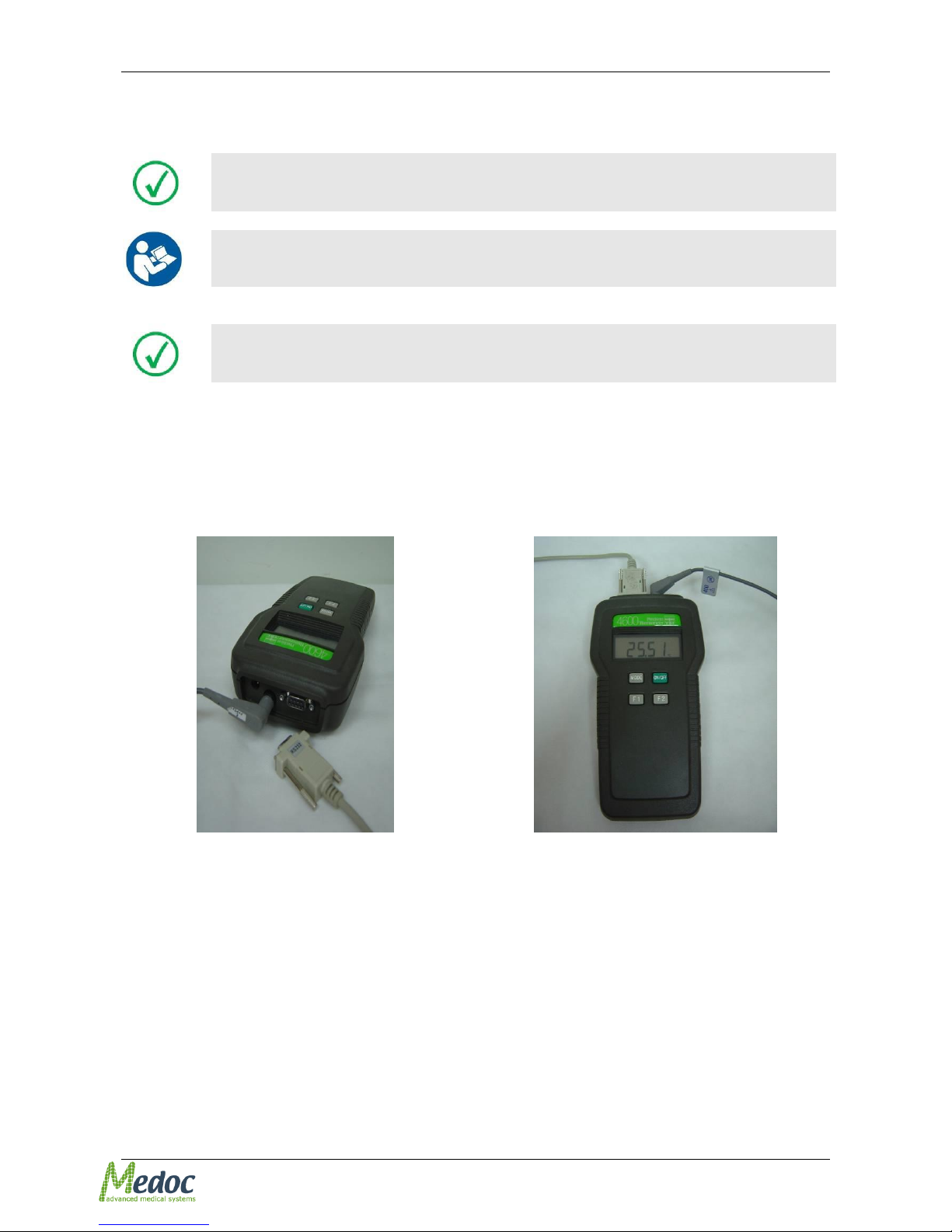
1. Connect the male RS232 communication cable to the 9 pin, D-type connector on the YSI
Precision thermometer.
Figure 15: Thermometer D-type Connector
Figure 16: Thermometer Communication
Connection
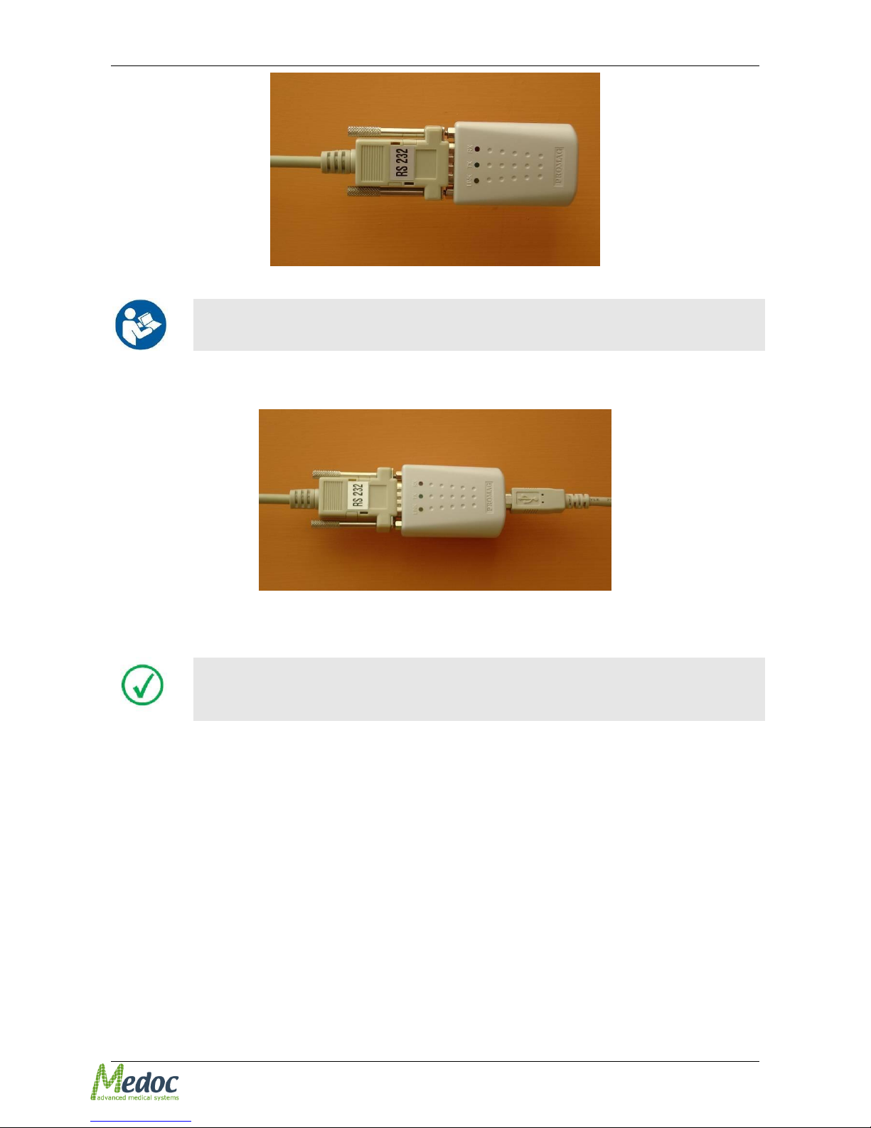
2. Connect the female end of the RS232 communication cable to the RS232- to-USB adapter.
Page 28
Pathway Technical Reference Service Manual
Proprietary 28 of 44
Figure 17: RS232-to-USB Adapter Connection
You may need to install the driver for the RS232-to-USB adapter on your
PC. Refer to section 5, Page 44.
Connect the RS232-to-USB adapter to the USB cable connector. Connect the cable to a USB port
on the same computer that is connected to Q-SENSE system.
Figure 18: USB cable connection
Check which COM port is used for communication between the YSI
Thermometer and your PC. This can be done by using the device
manager on your computer.
3.4.2 Automatic Calibration Procedure
1. Make sure you have completed all instructions mentioned in section 3.4.1, page 27
(Thermometer Communication Setup).
2. Turn the Thermometer ON.
3. Start the Q-SENSE program and make sure that communication is established between the PC
and the Q-SENSE system.
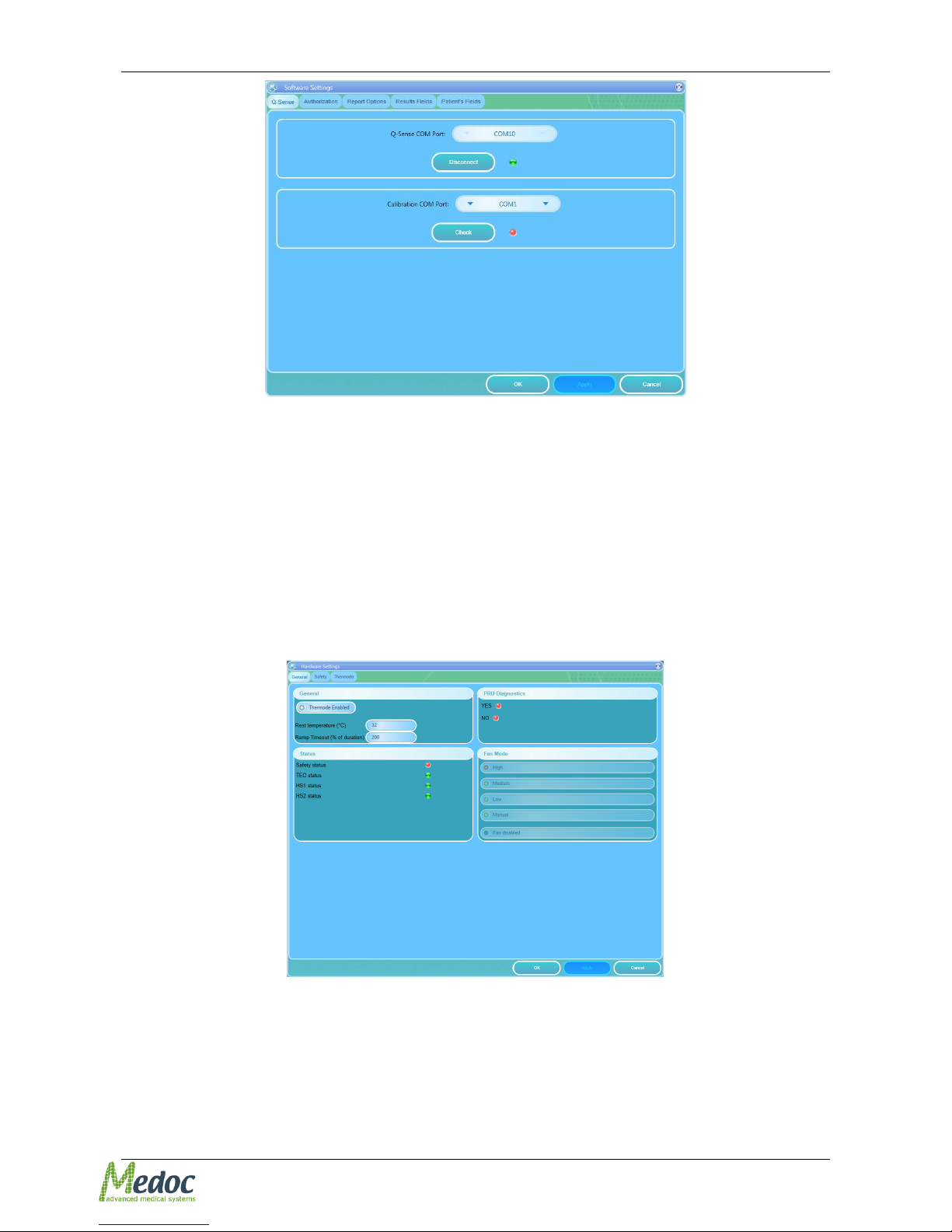
4. From the Settings menu, select the Software Settings option.
The following screen is displayed:
Page 29
Pathway Technical Reference Service Manual
Proprietary 29 of 44
Figure 19: Calibration port selection
5. From the Calibration COM port drop down list, select the appropriate COM port for the YSI
thermometer, according to the COM port to which it is connected.
6. Check whether communication with the YSI thermometer can be established, by pressing the
Check button.
Green light indicates “pass”.
Red light indicates “fail”. In case of a failure, make sure that all communication cables are
connected properly and that you have selected the correct COM port.
7. Click the OK button.
8. From the Settings menu, select the Hardware Settings option.
The following screen is displayed:
Figure 20: Hardware Settings Menu
9. Select the Thermode tab.
The following screen is displayed:
Page 30
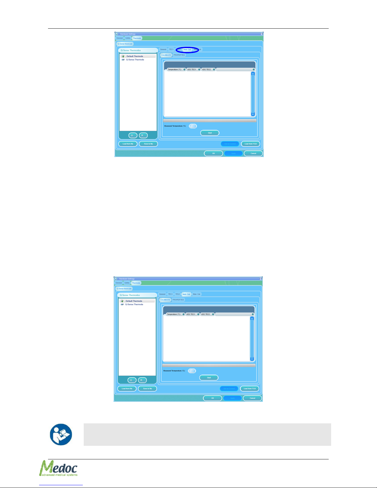
Pathway Technical Reference Service Manual
Proprietary 30 of 44
Figure 21: Thermode Calibration – Thermode
The displayed window includes additional tab:
Automatic Calibration tab (blue mark).
10. Select the required Thermode you wish to calibrate, according to your system configuration (Q-
sense).
11. From the Thermode name list on the left sidebar, select the Thermode you wish to calibrate (for
further details regarding Thermode type and Thermode name see the Thermode management
section 1, page 6).
12. Click the Set as current button. Make sure that the icon of the selected Thermode is marked
by a green check-mark.
13. Select the Automatic Calibrate tab.
The following screen is displayed:
Figure 22: Thermode Automatic Calibration
For further information and manual adjustment of the automatic
calibration properties see section 3.4.4, page 31.
Page 31
Pathway Technical Reference Service Manual
Proprietary 31 of 44
14. Make sure that the YSI thermometer is turned ON, that it is connected properly to your
computer, and that the selected Thermode is placed in the calibration jig.
15. Click the Start button.
A conformation message is displayed, reminding you to check the connection, and pay extra
attention to Thermode temperature.
16. Confirm by clicking YES. The automatic calibration procedure will start.
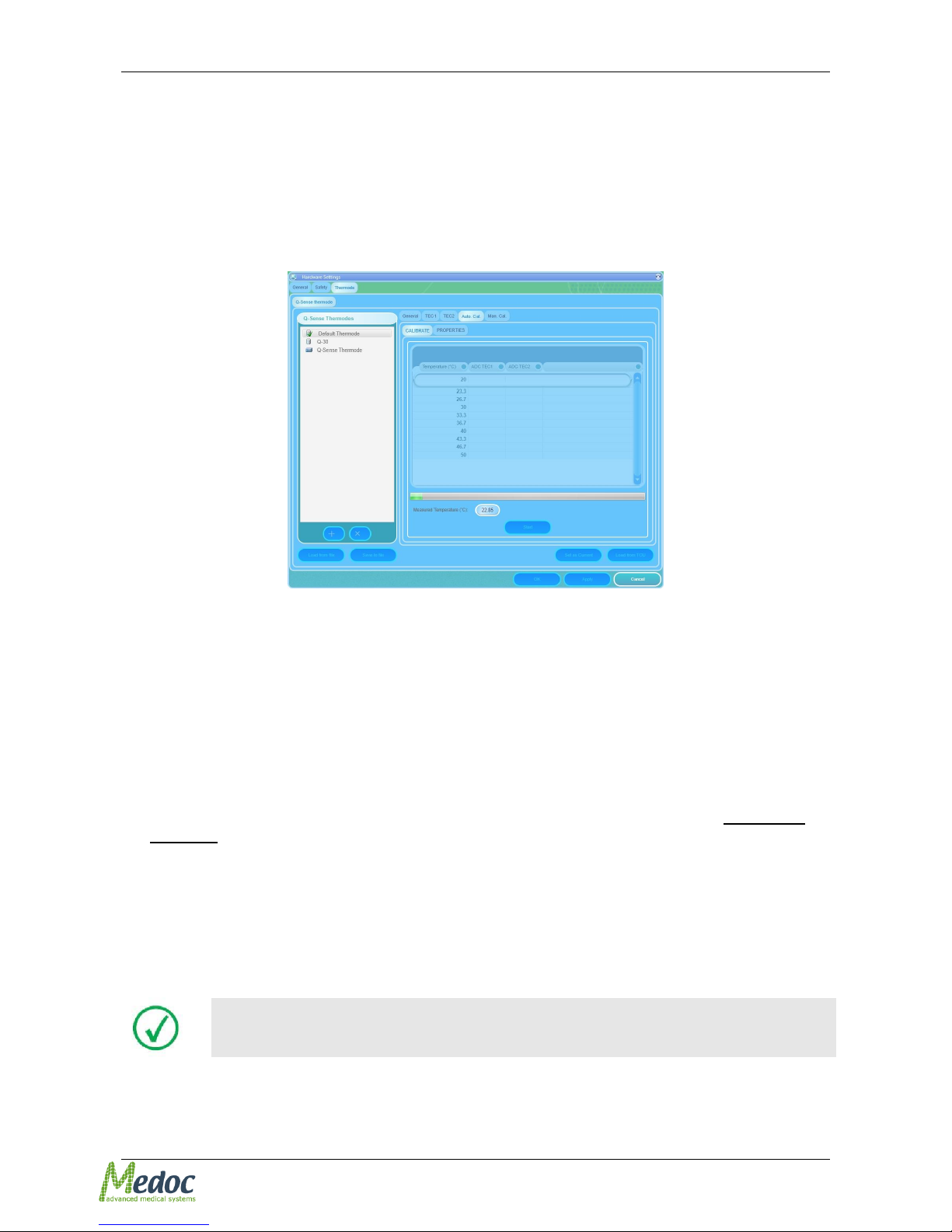
The following screen is displayed:
Figure 23: Automatic Calibration Progress
The calibration procedure is now in progress.
17. Wait until the automatic calibration procedure is complete.
The Q-SENSE system sets the new calibration table as current by default.
18. Click the OK button.
3.4.3 Concluding Steps
1. Remove the Thermode from the mechanical jig, by releasing the Velcro strips.
2. Clean the thermal grease from the sensor and Thermode, by using a clean cloth without any
detergent.
3. Remove the Thermode adaptor from the mechanical jig body.
4. Disconnect the YSI thermometer communication cable.
5. Pack the calibration kit into its case.
3.4.4 Automatic Calibration Properties
The automatic calibration properties allow you to manually adjust the calibration parameters.
Only software administrator is allowed to manually change calibration
properties!
In order to access and adjust the calibration properties follow these instructions:
1. From the Settings menu, select the Hardware Settings option Thermode tab.
Page 32
Pathway Technical Reference Service Manual
Proprietary 32 of 44
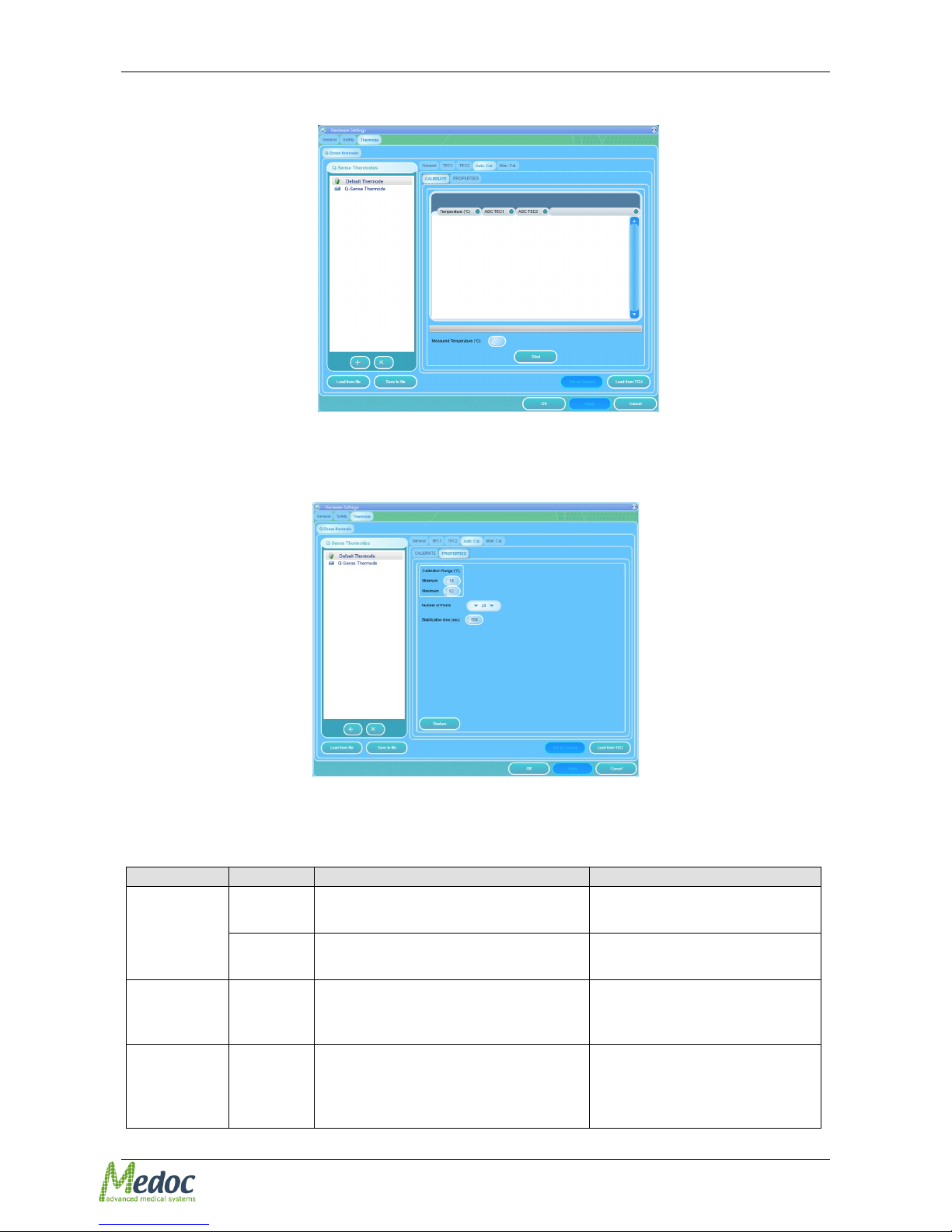
2. Select the Auto. Cal. tab.
the following screen is displayed:
Figure 24: Automatic Calibration tab
3. Select the Properties tab.
the following screen is displayed:
Figure 25: Automatic Calibration Properties tab
4. Automatic calibration properties can be changed according to the following table:
Table 6: Automatic Calibration Properties
Parameter
Description
Valid Range
Calibration
Range
Minimum
The minimum temperature that the
automatic calibration will check.
18°C - 22°C (Standard)
Maximum
The maximum temperature that the
automatic calibration will check.
48°C - 51°C (Standard)
Number of
Points
The number of points that the
automatic calibration procedure will
calibrate.
10 15 20 28
Stabilize
Time
The stabilization duration that is
required before sampling
temperature at each temperature
point.
120 – 1200 sec
Page 33
Pathway Technical Reference Service Manual
Proprietary 33 of 44
3.5 Manual Calibration
Medoc highly recommends reading carefully sections 3.5.1 through 3.5.4
before proceeding with Thermode calibration.
3.5.1 Manual Calibration Procedure
1. Make sure you have completed all instructions mentioned in section 3.3, page 25 (Calibration
Setup).
2. Start the Q-SENSE program and make sure that communication is established between PC
and the Q-SENSE system.
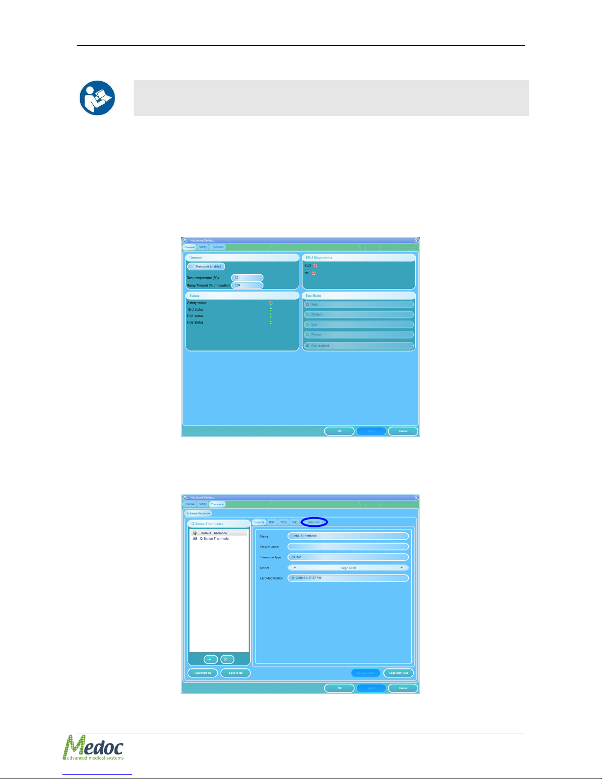
3. From the Settings menu, select the Hardware Settings option.
The following screen is displayed:
Figure 26: Hardware Settings Menu
4. Select the Thermode tab.
The following screen is displayed:
Figure 27: Thermode Calibration – General
Page 34
Pathway Technical Reference Service Manual
Proprietary 34 of 44
The displayed window includes additional tab:
Manual calibration tab (blue mark).
5. Select the required Thermode setting.
6. From the Thermode name list on the left side of the screen select the Thermode you wish to
calibrate (for further details regarding Thermode name see section 2, page 18).
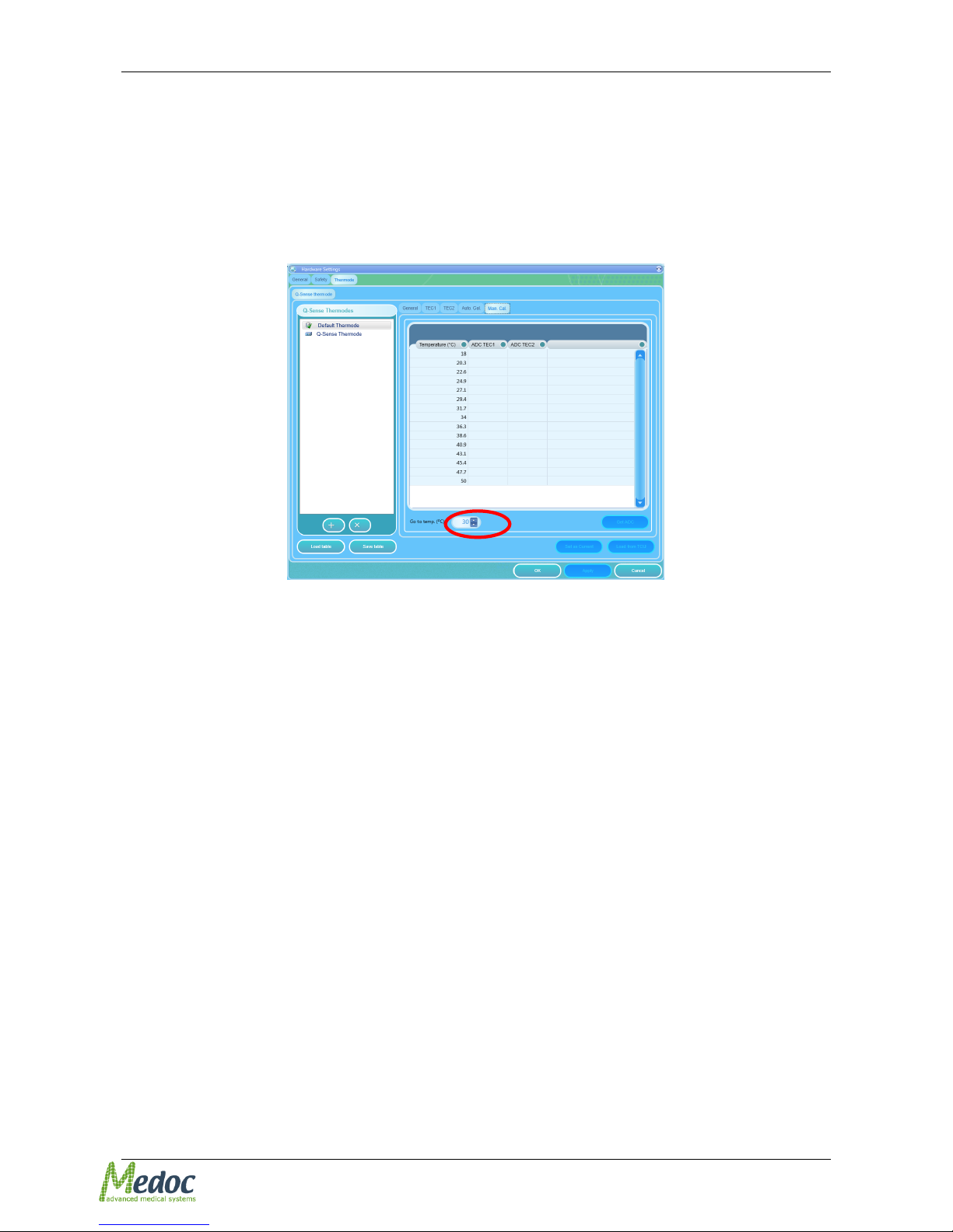
7. Select Man. Cal tab.
The following screen is displayed:
Figure 28: Thermode Calibration – Manual Calibration tab
The spin box (red mark) is used to set the required the Thermode temperature.
8. Select the first row in calibration field, corresponding to the first temperature.
9. Increase or decrease the temperature in the spin-box (circled in red, see Figure 28) using the
up / down arrows, until the temperature value displayed (in the spin box) is the same as the
Temperature (oC) value in the selected row. Alternatively, it is possible to type the required
value directly into the spin box.
10. Wait at least 2 minutes until you see that the temperature on the thermometer screen has
stabilized.
11. Replace the temperature value that appears in the selected row of the calibration screen with
the temperature value displayed on the thermometer screen.
For example: if the temperature in the selected row is 26.6, adjust the value in the spin-box to
26.6 by using the arrows (circled in red, see Figure 28). Wait about 2 minutes; then, type the
value that appears in the thermometer in the selected row, instead of the initial value of 26.6 in
this case.
12. Click the Get ADC button, and wait 3 seconds for Q-SENSE to calculate the corresponding
ADC value. After the calculated value is displayed in the row you can proceed.
13. Continue to the next row – to the next temperature you wish to calibrate.
14. Repeat steps 9-13, until the calibration table has been completed for all 15 temperature points.
15. Click the Apply button in order to save and complete the calibration calculations.
16. Click the General tab.
17. Click the Set as Current button in order to load the new calibration table to the Q-SENSE
system.
Page 35
Pathway Technical Reference Service Manual
Proprietary 35 of 44
3.5.2 Concluding Steps
1. Remove the Thermode from mechanical jig, by releasing the Velcro strips.
2. Clean the thermal grease from the sensor and Thermode, by using a clean cloth without any
detergent.
3. Remove the Thermode adaptor from the mechanical jig body.
4. Disconnect the YSI thermometer communication cable.
5. Pack the calibration kit into its case.
3.5.3 Manual Calibration properties
Only 15 out of the 30 pairs of values can be calibrated by the user. The remaining values are
calculated and filled-in automatically by Q-SENSE software.
The calibration range for user calibrated pairs is 18°C – 50°C
Calibrating temperature points that exceed the allowed range will cause
errors and calibration procedure will not be completed!
The required range is divided by default into 15 temperature points evenly spaced. These
temperatures are displayed in the calibration table and user is recommended to calibrate
according to these points.
The minimum number of pairs required to enable the automatic completion of the calibration
table is 10.
Q-SENSE system will automatically calculate and fill-in the remaining pairs according to
complete calibration range, see Table 5, Page 24
Medoc highly recommends performing a full calibration by calibrating all
15 temperature points.
3.5.4 Saving calibration tables and back-up:
Calibration table can be saved at any point during calibration procedure as a ".csv" file. To
save table click the Save table button and select location and file name for saving.
To load a saved table, click the Load table button. The loaded file must be in “.csv” fomat.
Medoc recommends saving the calibration table during the calibration
process in order to prevent any loses of data in case of communication
error during the process.
Page 36

Pathway Technical Reference Service Manual
Proprietary 36 of 44
3.5.5 Error and Warning messages
Table 7: Manual Calibration error and warning messages
Error/Warning Message
Reason
Resolution
“Sensor TEC : the number of defined
calibration table entries is less than
the required 10”
User calibrated less
than 10 points
Return to calibration
procedure and fill-in the
missing points.
“The number of defined calibration
table entries is more the than required
10, but less than the recommended
15”
User calibrated less
than recommended
15 points
Click YES to let Q-SENSE
program automatically fill-in
remaining points.
Click No to continue
calibration of remaining
values.
Page 37
Pathway Technical Reference Service Manual
Proprietary 37 of 44
4 Q-SENSE Firmware
Q-SENSE Firmware is the embedded software that runs and manages all system processes on the
Q-SENSE Main Board CPU.
Q-SENSE Firmware or license update should only be performed if required by Medoc or Medoc
local representative.
It is advisable that this procedure be carried out by a Q-SENSE system
administrator, and after consulting a Medoc service.
In order to update the system license and/or firmware the following equipment is required:
1. Allen screwdriver, size 4mm (not supplied with system)
2. JTAG Adaptor (not supplied with system, contact your local reprehensive if required)
3. Firmware update file
4. License file (required for license update)
4.1 Preparing the System for Firmware Update
1. Ensure Q-SENSE system is turned OFF, and disconnected from the power supply.
2. Disconnect Thermodes and accessories from the system.
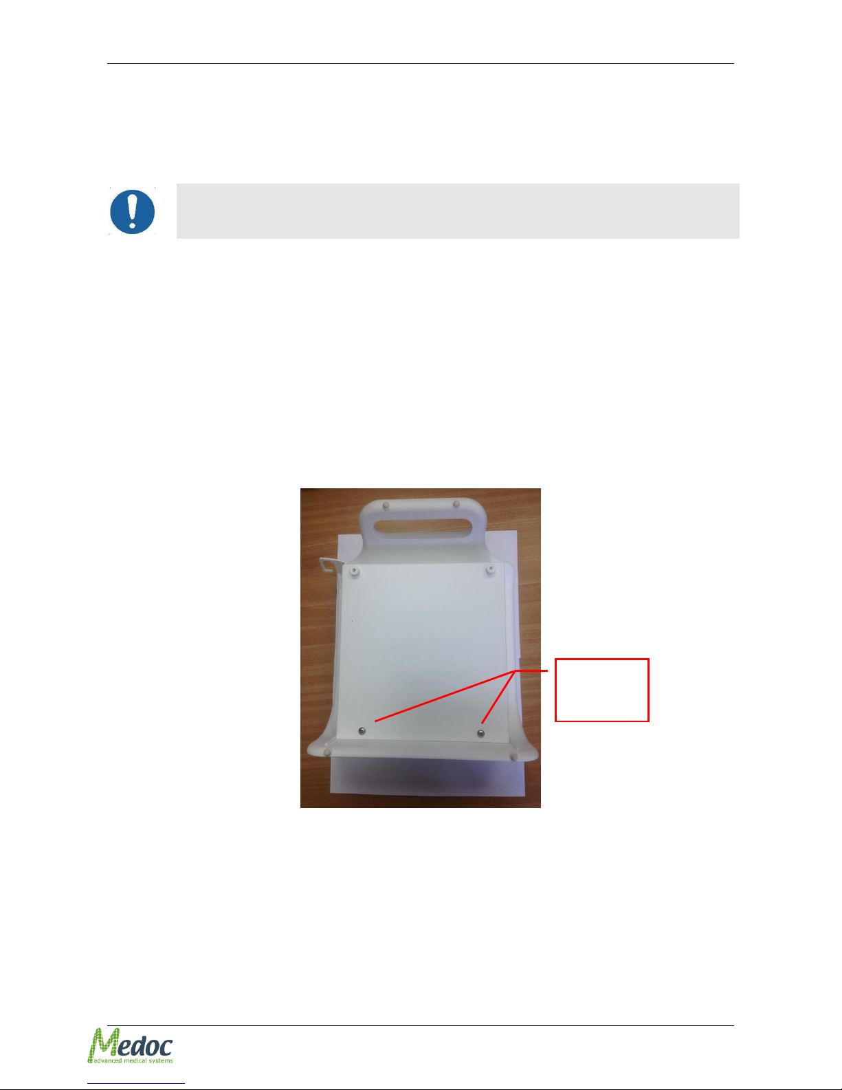
3. Unscrew the screws in the back of the Q-sense cover using Philips screwdriver.
Figure 29: Back of the Q-Sense cover
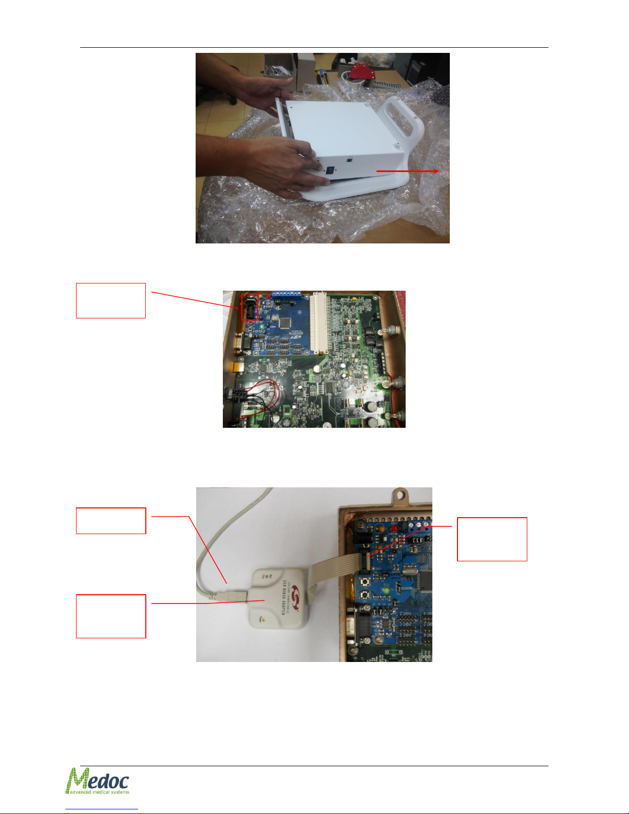
4. Lift gently the bottom part on the front (see Figure 30) and then push a little bit forward and
upward to release the internal pins (see Figure 36).
Back cover
screws
Page 38
Pathway Technical Reference Service Manual
Proprietary 38 of 44
Figure 30: Opening Q-Sense
5. Connect the JTAG adapter to the JTAG port on the Main Board (see Figure 31).
Figure 31: JTAG Port Location
6. Disconnect the communication USB cable from the COM USB port in the Q-SENSE system
and insert it into the JTAG USB port, see Figure 32
Figure 32: JTAG USB Port connected
There are few options for the firmware update as described below.
1. Firmware Update – Use this method when only firmware update is required. See section 4.2
2. Firmware and License Update – Use this method if license and firmware update is required.
See section 4.3
JTAG USB
port
USB cable
JTAG
adaptor
JTAG port
connection
Page 39
Pathway Technical Reference Service Manual
Proprietary 39 of 44
4.2 Firmware Update
In order to update the firmware alone, follow the instructions below:
1. Following instructions in section 4.1
2. Connect Q-Sense to the power Turn Q-SENSE system ON (do not reconnect the Thermode).
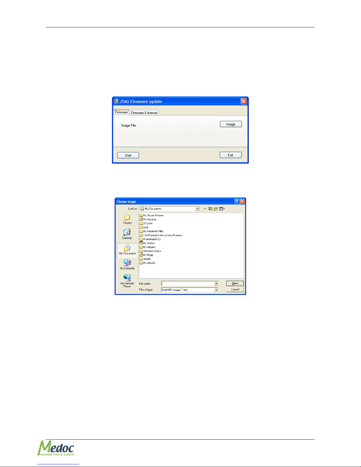
3. Start JTAG Firmware Update from the Start Menu: StartAll ProgramsMedoc Medoc
Main StationJTAG Firmware Update.
The following screen is displayed:
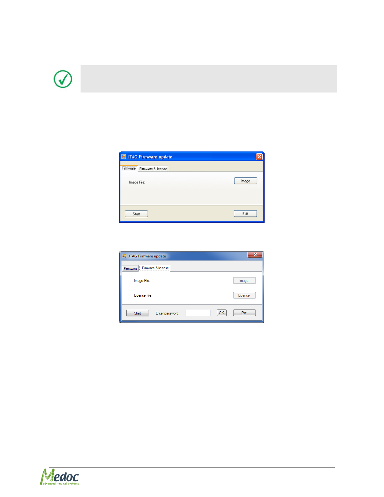
Figure 33: JTAG Firmware Update
4. Click the Image button
The Open screen is displayed
Figure 34: Choose Image
5. Browse to the location of the firmware update file (.hex file) and click Open button
6. Click the Start button, to start the firmware update process. The firmware update process
cannot be interrupted once it has started
7. After the update process has completed, a message will be displayed. Confirm the message
and click the Exit button to close the JTAG firmware update application.
8. Turn the Q-SENSE system OFF
9. Disconnect the JTAG adaptor from the main board
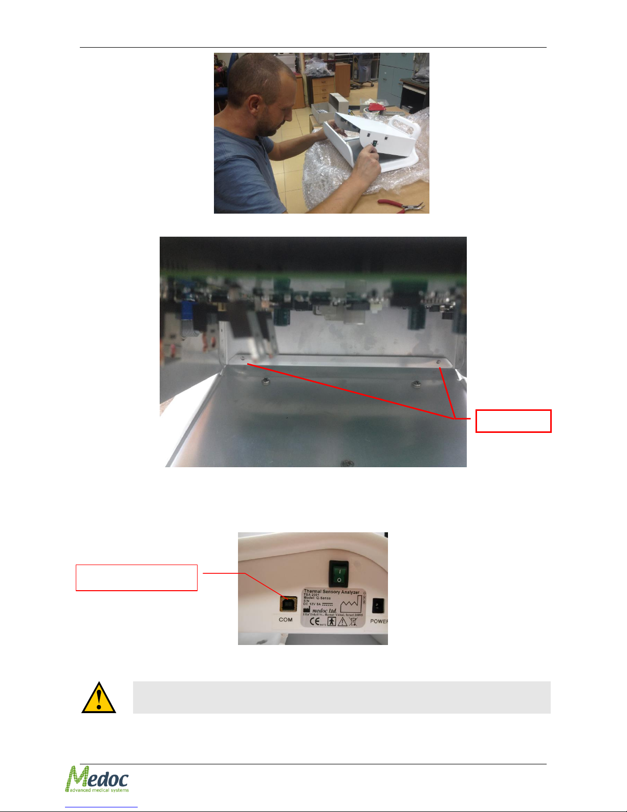
10. Close Q-Sense cover, make sure that internal pins are in place (see Figure 35, Figure 36) and
return the screws that connect top and bottom cover.
Page 40
Pathway Technical Reference Service Manual
Proprietary 40 of 44
Figure 35: Closing Q-Sense
Figure 36: Internal pins
11. Re-connect the USB to the COM port (Figure 37)
12. Connect the Thermode, Response Unit and Power supply.
Figure 37: Communication USB port
13. Turn the Q-SENSE system ON. System is now ready for use.
The Q-SENSE system must be restarted after the update process. It will
not work otherwise.
Communication port
Internal pins
Page 41

Pathway Technical Reference Service Manual
Proprietary 41 of 44
If the update process was not successful, repeat the entire procedure
from step 1. If there is still a malfunction, call Medoc service for
assistance.
Enable the Thermode after update procedure. For additional information
regarding Thermode Management refer to section 2.1 , page 17.
Page 42
Pathway Technical Reference Service Manual
Proprietary 42 of 44
4.3 Firmware and License Update
In order to update the firmware and license, follow the instructions below.
Make sure you have both firmware update file (*.hex) and license file (*.lir)
before starting the firmware and license update process.
1. Following instructions in section 4.1
2. Connect Q-Sense to the power Turn Q-SENSE system ON (do not reconnect the Thermode).
3. Start JTAG Firmware Update from the Start Menu: StartAll ProgramsMedoc Medoc
Main StationJTAG Firmware Update.
The following screen is displayed:
Figure 38: JTAG Firmware Update
4. Open the Firmware & License tab. The following screen is displayed:
Figure 39: Firmware & License Update
5. Enter the password and click OK to activate the screen (the password should be supplied by
Medoc / Medoc local representative in case firmware and license update is required).
6. Click the Image button and browse to the location of the firmware update file (*.hex). Click
Open to select.
7. Click the License button and browse to the location of the license file (*.lir). Click Open to
select.
8. Click the Start button, to start the firmware update process. The firmware update process
cannot be interrupted once it has started
9. After the update process has completed, a message will be displayed. Confirm the message
and click the Exit button to close the JTAG firmware update application.
10. Turn the Q-SENSE system OFF
11. Disconnect the JTAG adaptor from the main board
12. Close the top cover and return the screws that connect top and bottom cover.
13. Re-connect the USB to the COM port (Figure 37)
Page 43
Pathway Technical Reference Service Manual
Proprietary 43 of 44
14. Connect the Thermode, Response Unit and Power supply.
15. Turn the Q-SENSE system ON. System is now ready for use.
16. Start Medoc Main Station and establish communication with Q-Sense.
17. Enable the Thermode before performing system self-test for the first time after the firmware
update
The Q-SENSE system must be restarted after the update process. It will
not work otherwise.
If the update process was not successful, repeat the entire procedure
from step 1. If there is still a malfunction, call Medoc service for
assistance.
Enable the Thermode after update procedure. For additional information
regarding Thermode Management refer to section 2.1 , page 17.
Page 44
Pathway Technical Reference Service Manual
Proprietary 44 of 44
5 Appendix A – RS232-USB Adaptor Driver
Adapter type may vary; therefore the driver name may change during
installation.
Make sure the RS232-to-USB adaptor is not connected to your PC before
starting the driver installation procedure.
The RS-232 to USB driver is automatically installed during installation of Medoc Main Station. This
driver is used only for communication with Thermometer. In case it is needed to reinstall follow the
instructions below:
In order to install the RS232-USB adaptor, perform the following procedure:
1. Insert the installation CD supplied by Medoc to the CD drive in your notebook
2. Once the Q-sense installation wizard is displayed, click Cancel; then Yes; then Finish
The Q-sense installation wizard closes
3. Browse the installation CD folder for the USB-RS232 driver installation file: CDM20600.exe
(number may vary).
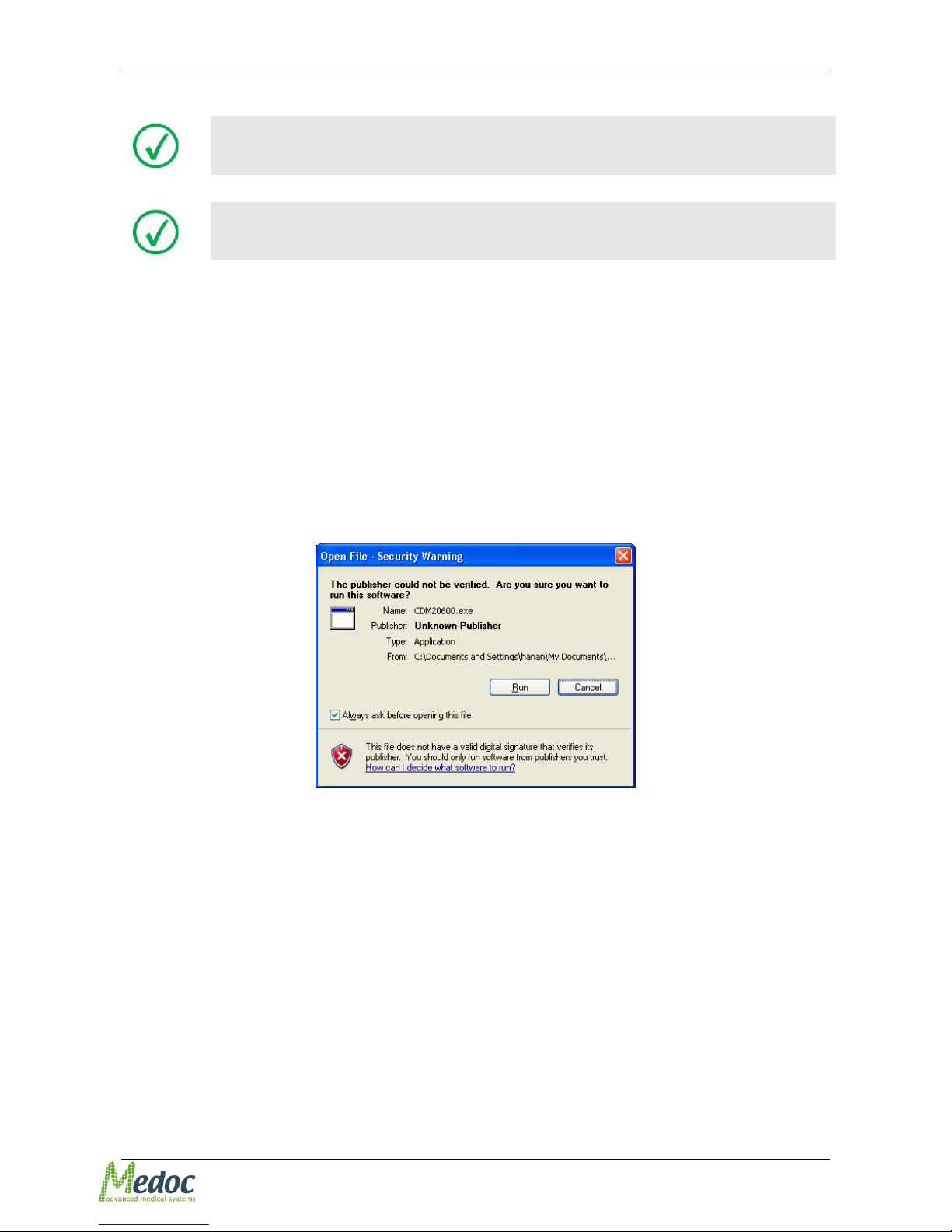
4. Double click the executable file CDM20600.exe
The following screen is displayed:
Figure 40: RS232-USB driver installation notification
5. Press Run to install the USB-RS232 driver
6. A window will open notifying that the driver installation is in process
7. When the window closes, Driver installation is complete
8. Connect the USB-RS232 adapter to the USB cable
9. You may verify the driver installation from the computer Device Manager, Ports (COM & LPT)
 Loading...