

Page 1
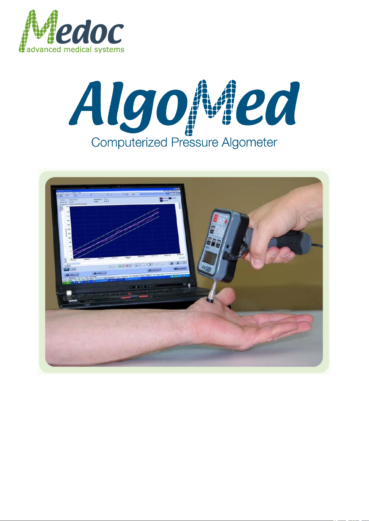
Technical Reference
Manual
Page 2
AlgoMed Technical Reference Manual Table of Contents
This device complies with 93/42/EEC
MDD
This User Manual contains proprietary information of Medoc Ltd. and may not be reproduced in
any form without prior written consent from Medoc Ltd.
DC 00408 AlgoMed Technical Reference Manual, 16th Ed. October 2018
Medoc Ltd.
1 Ha-Dekel St., PO Box 423 Ramat Yishai 3004627, ISRAEL
Tel.: +972-4-9038800 / Fax: +972-4-9038808
E-Mail [email protected]
Medoc U.S.A
Compass Medical Technologies, Inc.
1502 West Highway 54 - Suite 404
Durham, North Carolina, 27707, U.S.A
Tel.: +1-(919) 402-9600 / Fax: +1-(919) 402-9607
E-Mail: [email protected]
European Authorized Representative
CEpartner4U BV
Esdoornlaan 13 3951 DB Maarn, The Netherlands
Phone: +31 343 442.524 / Fax: +31 343 442 162
Mobile: +31 6 516 536.26
E-Mail: [email protected]
0473
Proprietary 2 of 110
Page 3

AlgoMed Technical Reference Manual Table of Contents
Table of Contents
1. Safety Guidelines and Regulations ............................................... 9
1.1 User Manual Icons.......................................................................................... 9
1.2 Intended use ................................................................................................ 10
1.3 Safety and Regulatory Summary .................................................................. 10
1.4 Safety Requirements .................................................................................... 10
1.4.1 Warnings ................................................................................................. 10
1.4.2 Cautions .................................................................................................. 11
1.4.3 Equipment Classification ............................................................................ 11
1.5 System Protection ........................................................................................ 12
1.6 Equipment Labels, Symbols, Warning Statements and Abbreviations .......... 12
1.7 Electromagnetic immunity ........................................................................... 13
1.8 Recommended Separation Distance between portable and mobile RF
communications equipment and AlgoMed ............................................................. 16
1.9 Technical Data.............................................................................................. 17
2. Overview .................................................................................... 19
2.1 AlgoMed Computerized Pressure Algometer ................................................. 19
2.2 System Status .............................................................................................. 19
2.3 Application Methods ..................................................................................... 19
2.3.1 Limits Method ........................................................................................... 20
2.3.2 Ramp and Hold Method .............................................................................. 20
3. System Components ................................................................... 21
4. Setup and Installation ................................................................ 24
4.1 Computer Requirements .............................................................................. 24
4.2 Installation USB Content .............................................................................. 25
4.3 Installation Main Steps ................................................................................ 25
4.4 Selecting a Location ..................................................................................... 25
4.5 Software Installation ................................................................................... 25
4.6 Unit Protection ............................................................................................. 26
4.7 Product Activation ........................................................................................ 26
5. Operation ................................................................................... 28
5.1 Safety ........................................................................................................... 28
5.2 Starting the AlgoMed System ....................................................................... 29
5.3 Connecting to the AlgoMed Manually............................................................ 31
5.4 Basic Operation – Terminology .................................................................... 32
5.4.1 Menu Bar ................................................................................................. 32
5.4.2 Toolbar .................................................................................................... 33
5.4.3 Search Row .............................................................................................. 33
5.4.4 Current Selection Information ..................................................................... 34
Proprietary 3 of 110
Page 4

AlgoMed Technical Reference Manual Table of Contents
5.4.5 Data Display Area ..................................................................................... 34
5.4.6 Status Line ............................................................................................... 34
6. Test Management ....................................................................... 35
6.1 Selecting a Patient ....................................................................................... 35
6.2 Selecting a Program ..................................................................................... 38
6.3 Selecting a Body Site .................................................................................... 40
6.4 Running a Test ............................................................................................. 41
6.4.2 Test Run Hot Keys ..................................................................................... 46
7. Program Management ................................................................ 47
7.1 Program List ................................................................................................ 47
7.2 Creating a New Program .............................................................................. 49
7.3 Editing Program Parameters ........................................................................ 50
7.3.1 Program Details ........................................................................................ 50
7.3.2 Standard Events ....................................................................................... 54
7.4 Unique Test Instructions .............................................................................. 55
7.5 Removing A Program ................................................................................... 55
7.6 Duplicate A Program .................................................................................... 56
7.7 Edit A Program ............................................................................................. 56
7.8 Import / Export Program ............................................................................. 56
8. Patient Management .................................................................. 57
8.1 Patients List ................................................................................................. 57
8.2 Add New Patient .......................................................................................... 59
8.3 Remove Patient ............................................................................................ 59
8.4 Edit Patient Details....................................................................................... 60
8.5 Department Management ............................................................................. 60
8.6 Import / Export Patient Lists ....................................................................... 60
9. Results Management .................................................................. 62
9.1 Results List .................................................................................................. 62
9.2 Import / Export Results ............................................................................... 64
9.3 Print Results and Reports ............................................................................. 65
9.3.1 Analysis Report Dialog ............................................................................... 65
10. System Configuration ................................................................. 76
10.1 Software Settings...................................................................................... 76
10.1.1 Communication ......................................................................................... 77
10.1.2 Patient Fields ............................................................................................ 78
10.1.3 Results Fields ........................................................................................... 80
10.1.4 Report Options ......................................................................................... 80
10.1.5 Buttons Configuration ................................................................................ 82
10.1.6 Users ....................................................................................................... 82
Proprietary 4 of 110
Page 5

AlgoMed Technical Reference Manual Table of Contents
10.2 Hardware Settings .................................................................................... 85
10.3 Test Settings ............................................................................................. 88
10.3.1 Test Configuration ..................................................................................... 89
10.3.2 Instructions Configuration .......................................................................... 90
10.3.3 Body Site Editor ........................................................................................ 92
10.3.4 Event Marker ............................................................................................ 93
10.3.5 Event Sound Configuration ......................................................................... 94
11. System Information ................................................................... 96
12. Appendix A – Accessories ........................................................... 98
13. Appendix B – System and Module Description ............................ 99
13.1 System Description ................................................................................... 99
14. Appendix C – Preventive and Periodical Maintenance ............... 100
14.1 Periodical Visual Check ........................................................................... 100
14.2 Calibration Verification ........................................................................... 100
14.3 Algometer Calibration ............................................................................. 102
15. Appendix D – Cleaning and Disinfecting ................................... 103
16. Appendix E – List of Accompanying Documents ........................ 104
17. Appendix F – Transportation and Storage conditions ............... 105
18. Appendix G – Environmental Conditions ................................... 106
19. Appendix H – Technical Specifications ...................................... 107
19.1 Hardware Specifications ......................................................................... 107
19.2 Software Specifications ........................................................................... 108
20. Appendix I – Troubleshooting .................................................. 110
Proprietary 5 of 110
Page 6

AlgoMed Technical Reference Manual List of Figures
List of Figures
Figure 1: AlgoMed Label ............................................................................................... 12
Figure 2: AlgoMed Computerized Pressure Algometer ....................................................... 19
Figure 3: AlgoMed Case ................................................................................................ 21
Figure 4: AlgoMed Case ................................................................................................ 21
Figure 5: Home screen product registration link .............................................................. 27
Figure 6: Warping the tip ............................................................................................. 28
Figure 7: AlgoMed On / OFF button ................................................................................ 29
Figure 8: Device selection Screen .................................................................................. 29
Figure 9: Login Screen ................................................................................................. 30
Figure 10: Welcome Screen .......................................................................................... 30
Figure 11: Connecting to the AlgoMed ............................................................................ 31
Figure 12: TEST Sceen - Main Menu ............................................................................... 32
Figure 13: Test Management Main Screen ...................................................................... 35
Figure 14: Patient Selection Menu ................................................................................. 36
Figure 15: Patient Details Screen .................................................................................. 37
Figure 16: Programs List .............................................................................................. 38
Figure 17: Program Details screen ................................................................................. 39
Figure 18: Select Body Site screen ................................................................................ 40
Figure 19: Select Body Site – Specific site selection ......................................................... 40
Figure 20: Algometer Pre-Test Screen ............................................................................ 41
Figure 21: Algometer Pre-Test Screen ............................................................................ 42
Figure 22: Algometer Test Screen ................................................................................. 43
Figure 23: Time before test countdown .......................................................................... 44
Figure 24: Start applying pressure message ................................................................... 44
Figure 25: Real-Time Algometer Limits Test .................................................................... 46
Figure 26: Program Management screen ........................................................................ 47
Figure 27: Program Management – Program Preview ....................................................... 48
Figure 28: Program graph preview................................................................................. 49
Figure 29: New Program Screen .................................................................................... 49
Figure 30: Algometer Program Menu – Limits .................................................................. 51
Figure 31: Algometer Program Menu – Ramp & Hold ........................................................ 52
Figure 32: Limits – Standard Events Dialog .................................................................... 54
Figure 33: Ramp & Hold – Standard Events Dialog .......................................................... 54
Figure 34: Test Instructions Editor ................................................................................. 55
Figure 35: Patients List ................................................................................................ 57
Figure 36: Patient Management – Patient details preview ................................................. 58
Figure 37: Patients Editor Screen .................................................................................. 59
Figure 38: Edit Department Menu .................................................................................. 60
Proprietary 6 of 110
Page 7

AlgoMed Technical Reference Manual List of Tables
Figure 39: Results List ................................................................................................. 62
Figure 40: Result preview display .................................................................................. 63
Figure 41: Analysis Reports Dialog ................................................................................ 65
Figure 42: Analysis Report ............................................................................................ 66
Figure 43: Algometer Example of Single Report ............................................................... 68
Figure 44: Algometer Example of Bilateral Report ............................................................ 70
Figure 45: Software Settings Dialog ............................................................................... 76
Figure 46: Patient Fields Configuration Screen ................................................................ 78
Figure 47: Results Fields Configuration Screen ................................................................ 80
Figure 48: Report Options tab ....................................................................................... 81
Figure 49: Buttons configuration Software Settings ......................................................... 82
Figure 50: User Authorization Software Settings .............................................................. 82
Figure 51: CoVas calibration ......................................................................................... 86
Figure 52: CoVAS calibration wizard .............................................................................. 86
Figure 53: CoVAS Slider Calibration ............................................................................... 87
Figure 54: CoVAS Calibration Results ............................................................................. 87
Figure 55: CoVAS Calibration Finish Screen .................................................................... 88
Figure 56: Test Configuration Settings ........................................................................... 89
Figure 57: Instructions Configuration ............................................................................. 90
Figure 58: Test Instructions Editor ................................................................................. 91
Figure 59: Audio save button ........................................................................................ 92
Figure 60: Body Sites Editor ......................................................................................... 92
Figure 61: Event Marker ............................................................................................... 94
Figure 62: Event Sound Configuration ............................................................................ 95
Figure 63: Sound effect library ...................................................................................... 95
Figure 64: System Information ..................................................................................... 96
Figure 65: Sysinfo File Sample ...................................................................................... 97
Figure 66: System Diagram .......................................................................................... 99
Figure 67: Set units to Kgf .......................................................................................... 101
Figure 68: End of synchronization................................................................................. 101
Figure 69: Placing weight ............................................................................................ 102
Figure 70: Weight placed ............................................................................................. 102
List of Tables
Table 1: Equipment Labels ........................................................................................... 12
Table 2: AlgoMed Specifications .................................................................................... 17
Table 3: Algomed model specifications differences ........................................................... 18
Table 4: AlgoMed system components............................................................................ 22
Table 5: Menu Bar options ............................................................................................ 32
Table 6: Algometer Test Run features and options ........................................................... 44
Proprietary 7 of 110
Page 8

AlgoMed Technical Reference Manual List of Tables
Table 7: Hot Keys ........................................................................................................ 46
Table 8: Program Details .............................................................................................. 51
Table 9: Program Parameters ....................................................................................... 51
Table 10: Program Details ............................................................................................ 53
Table 11: Program Parameters ...................................................................................... 53
Table 12: Events - Limits .............................................................................................. 54
Table 13: Events – Ramp & Hold ................................................................................... 54
Table 14: Report Analysis Configuration ......................................................................... 66
Table 15: Report Analysis Configuration ......................................................................... 75
Table 16: Software Settings - General............................................................................ 77
Table 17: Patient’s Field ............................................................................................... 78
Table 18: Patient’s Field ............................................................................................... 80
Table 19: Report Options.............................................................................................. 81
Table 20: Authorization parameters ............................................................................... 83
Table 21: Authorization Levels (main actions) ................................................................. 83
Table 22: Test Settings Options .................................................................................... 88
Table 23: Test Settings Options .................................................................................... 89
Table 24: Accessories .................................................................................................. 98
Table 25: Hardware Specifications ................................................................................ 107
Table 26: Software Specifications ................................................................................. 108
Table 27: Error Messages and Action Required ............................................................... 110
Proprietary 8 of 110
Page 9
AlgoMed Technical Reference Manual
Disclaimer
Medoc assumes no liability for use of this document if any unauthorized changes to the
content or format have been made. Every care has been taken to ensure the accuracy of
the information in this document. However, Medoc assumes no responsibility or liability for
errors, inaccuracies, or omissions that may appear in this document. Medoc reserves the
right to change the product without further notice to improve reliability, function or design.
This manual is provided without warranty of any kind, implied or expressed, including, but
not limited to, the implied warranties of merchantability and fitness for a particular purpose.
Warning: A condition that could cause serious injury or death to a patient
and/or operator if instructions are not followed.
Caution: A condition that could cause possible damage to equipment or
cause the system to function inaccurately.
Note: Indicates important user information regarding the use of the
system.
Advice: Refer to instruction manual/ booklet
1. Safety Guidelines and Regulations
This manual is written for trained users of Medoc Products. The user includes the body with
authority over the equipment and those persons who actually handle the equipment.
Before attempting to work with this equipment, read, understand, note and strictly observe all
Warning notices, Cautions and Safety markings on the equipment.
Before attempting to work with this equipment, make sure that this manual and any Release
Notes delivered with the software media pack have been thoroughly read and fully understood,
paying particular attention to all:
1. Warnings
2. Cautions
3. Notes
4. Important Notices
5. User Notices
1.1 User Manual Icons
The following icons are used throughout the user manual:
Proprietary 9 of 110
Page 10
AlgoMed Technical Reference Manual
INSTRUCTION: Indicates an instruction where it is important to follow
the user manual literally as described.
The AlgoMed system can be tested according to IEC 62353 Recurrent test
and test after repair of medical electrical equipment.
Do not modify or replace any component of the AlgoMed system.
Connecting or replacing external AlgoMed accessories is allowed.
Keep all liquids away from the AlgoMed system.
Unplug the AlgoMed system if it is not to be used for a long period of time.
1.2 Intended use
The use of the AlgoMed system should be as intended by Medoc Ltd. and as specified in the
user manual. The AlgoMed is a pain management and pain research system intended to be
used for the quantitative assessment of small nerve fiber dysfunctions. It measures sensory
pain thresholds and tolerance.
1.3 Safety and Regulatory Summary
Read and follow all WARNINGS, CAUTIONS and NOTES provided in this manual. To avoid the
possibility of injury, damage to your system, or loss of data, always follow these precautions
during system operation.
The AlgoMed system complies with safety requirements for medical electrical systems
(based on the IEC 60601-1 standard).
The AlgoMed system complies with electromagnetic emission levels (based on table 201 in
the IEC 60601-1-2 standard).
The AlgoMed system complies with electromagnetic immunity levels (based on tables 202
and 204 in the IEC 60601-1-2 standard).
This device complies with 93/42/EEC MDD.
It is recommend keeping a distance of 3 meters between portable and mobile RF
communications equipment and the AlgoMed (based on table 206 in the IEC 60601-1-2
standard).
1.4 Safety Requirements
1.4.1 Warnings
Only personnel properly trained to operate the AlgoMed system should use this system.
Do not turn on system power until all cables have been properly connected and verified.
The Algometer tip must be covered with a standard disposable biocompatible finger cot
before it is placed on the skin.
The computer that is used to operate the AlgoMed system must be powered through
Medical Grade Isolation Transformer only.
The computer that is used to operate the AlgoMed system must never be connected to
network while it is used for running tests.
Proprietary 10 of 110
Page 11

AlgoMed Technical Reference Manual
The use of accessories or cables other than those specified, with the exception of
accessories or cables sold by the manufacturer as replacement parts, may result in
increased emissions or decreased immunity of the device.
Connecting any device or accessory that has no medical grade certificate to the AlgoMed
system is not allowed.
Using the AlgoMed system not according to instructions may result in potential harm or
injury.
Use of this equipment adjacent to or stacked with other equipment should be avoided
because it could result in improper operation. If such use is necessary, this equipment
and the other equipment should be observed to verify that they are operating normally.
Use of accessories, transducers and cables other than those specified or provided by the
manufacturer of this equipment could result in increased electromagnetic emissions or
decreased electromagnetic immunity of this equipment and result in improper operation.
Portable RF communications equipment (including peripherals such as antenna cables
and external antennas) should be used no closer than 30 cm (12 inches) to any part of
the Algomed, including cables specified by the manufacturer. Otherwise, degradation of
the performance of this equipment could result.
NOTE The EMISSIONS characteristics of this equipment make it suitable for use in
industrial areas and hospitals (CISPR 11 class A). If it is used in a residential
environment (for which CISPR 11 class B is normally required) this equipment might not
offer adequate protection to radio-frequency communication services. The user might
need to take mitigation measures, such as relocating or re-orienting the equipment
1.4.2 Cautions
Proper use of this device depends on careful reading of all instructions and labels.
Inspect the USB cables often for fraying or other damage. DO NOT operate the
apparatus if the USB cable is damaged.
The AlgoMed system does not require special precautions regarding EMC, and needs to
be installed and put into service according to this manual.
Portable and mobile RF communications equipment can affect medical electrical
equipment.
Contraindications: Use caution when using the AlgoMed device on patients with
suspected neuropathies as they may be more susceptible to soft tissue or nerve damage
at extreme pressure. In addition, patients with neuropathies may not be able to
properly discontinue use of the device during prolonged stimulation.
Test Subject should be trained to use the response unit before performing any test with
the AlgoMed system.
It is advised to verify AlgoMed calibration using the calibration verification weight before
using the AlgoMed. Refer to section 14, page 100.
1.4.3 Equipment Classification
Degree of protection against electric shock: Class I
Type of protection against electric shock: BF
Type of Operation: Continuous
Protection against ingress of liquids: Not protected against ingress of liquids
Proprietary 11 of 110
Page 12
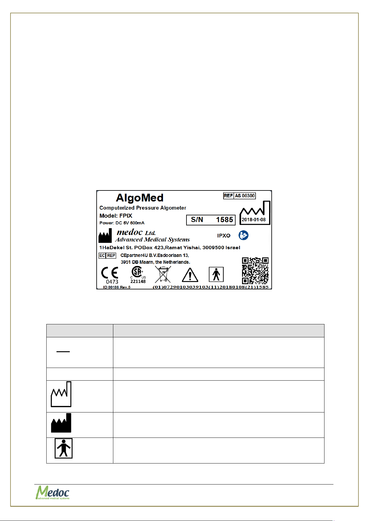
AlgoMed Technical Reference Manual
Equipment Label
Description
I
O
Power switch ON/OFF
COM
Communications connector.
Date of Manufacture (YYYY-MM)
Manufacturer
Degree of protection against electric shock – Applied Part Type
BF.
Ordinary equipment.
Computer must comply with IEC 950 - EN 60950 - UL 60950.
1.5 System Protection
Upon start-up the system performs a self-test in which system verify communication,
verify proper device configuration and reset load cell sensor
Upon test initialization the system performs reset load cell sensor
1.6 Equipment Labels, Symbols, Warning Statements and
Abbreviations
Figure 1: AlgoMed Label
Table 1: Equipment Labels
Proprietary 12 of 110
Page 13
AlgoMed Technical Reference Manual
Warning - Connect the device, according to the local electrical
standards.
Refer to Manual
Disposal according to electronic scrap ordinance
Manual edition refers to current version of manufactured system
Medoc reserves the right to change specification without prior notice, in line
with policy of constant product improvements
Immunity test
IEC 60601
test level
Compliance level
Electromagnetic
environment –guidance
Electrostatic discharge
(ESD) IEC 61000-4-2
8 kV contact
2, 4, 8, 15kV air
8 kV contact
2, 4, 8, 15kV air
Floors should be wood,
concrete or ceramic tile. If
floors are covered with
synthetic material, the
relative humidity should be
at least 30 %.
Power frequency
(50/60 Hz)
magnetic field
IEC 61000-4-4
3 A/m
50 & 60 Hz
3 A/m
50 & 60 Hz
Power frequency magnetic
fields should be at levels
characteristic of a typical
location in a typical
commercial or hospital
environment.
Electrical fast
transient/burst
±2 kV for power
supply lines
±2 kV for power
supply lines
Mains power quality should
be that of a typical
commercial or hospital
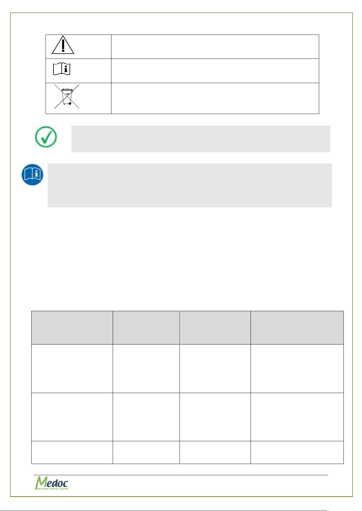
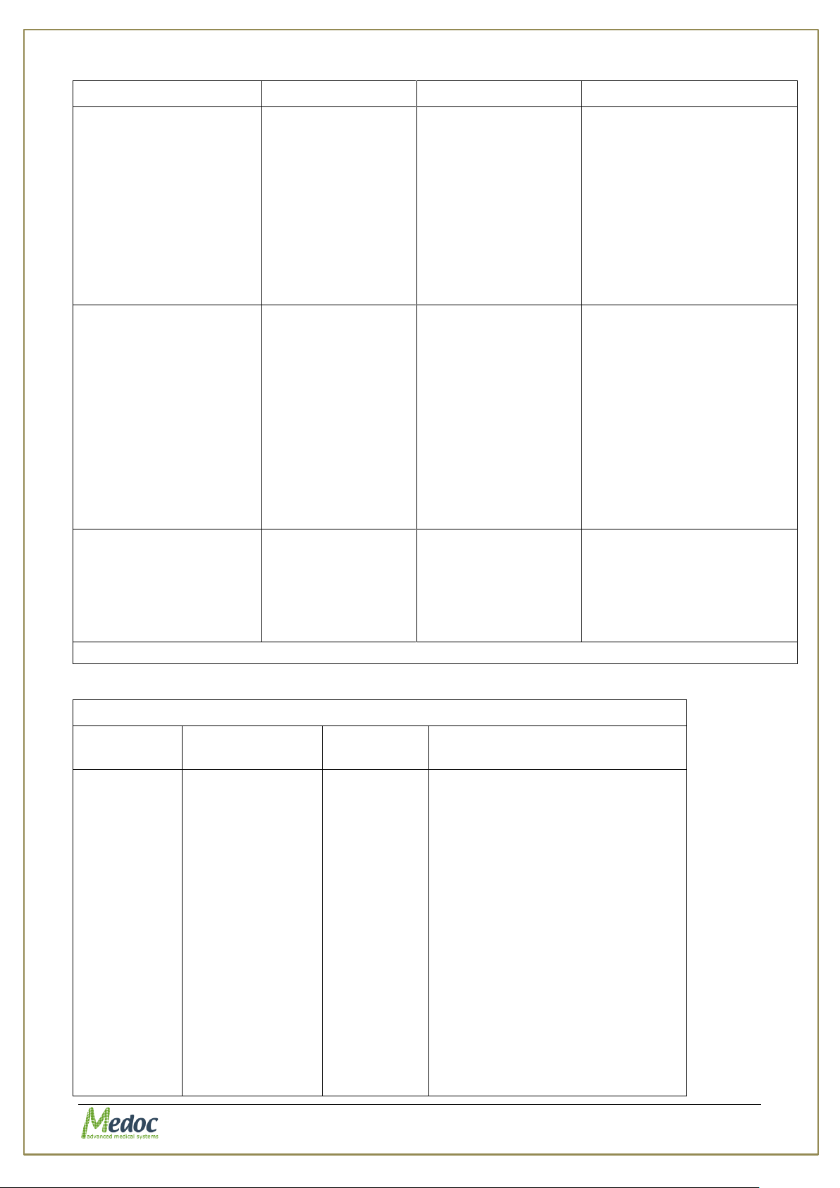
1.7 Electromagnetic immunity
The AlgoMed is intended for use in the electromagnetic environment specified below. The
customer or the user of the AlgoMed should assure that it is used in such an environment.
Proprietary 13 of 110
Page 14
AlgoMed Technical Reference Manual
Declaration – electromagnetic immunity
IMMUNITY
test
IEC 60601
TEST LEVEL
Compliance
level
Electromagnetic environment
– guidance
Conducted
RF
IEC 610004-6
Radiated RF
IEC 610004-3
3V, 6V
3V/m
3V from 0.15 to
80MHz;
3Vrms, 6V
3V/m
3V from
0.15 to
80MHz;
Portable and mobile RF
communications equipment
should be used no closer to any
part of the Algomed including
cables, than the recommended
separation distance calculated
from the equation applicable to
the frequency of the transmitter.
Recommended separation
distance
IEC 61000-4-4
environment.
Surge
IEC 61000-4-5
1 kV line(s) to
line(s)
2 kV line(s) to
earth
2 kV Signal
input/output) to
earth
1 kV line(s) to
line(s)
N/A
N/A
Mains power quality should
be that of a typical
commercial or hospital
environment.
Voltage dips, short
interruptions and
voltage variations on
power supply input lines
IEC 61000-4-11
0% UT; 0.5cycle at
0°, 45°, 90°,
135°,180°, 225°,
270° and 315°
0% UT; 1cycle and
70% UT; 25/30
cycles
Single phase at 0°
0% UT; 250/300
cycle
0% UT; 0.5cycle at
0°, 45°, 90°,
135°,180°, 225°,
270° and 315°
0% UT; 1cycle and
70% UT; 25/30
cycles
Single phase at 0°
0% UT; 250/300
cycle
Mains power quality should
be that of a typical
commercial or hospital
environment. If the user of
the Algomed requires
continued operation during
power mains interruptions,
it is recommended that the
Algomed
be powered from an
uninterruptible power
supply or a battery.
Power frequency (50/60
Hz) magnetic field
IEC 61000-4-8
30 (A/m)
30 (A/m)
Power frequency magnetic
fields should be at levels
characteristic of a typical
location in a typical
commercial or hospital
environment.
NOTE UT is the a.c. mains voltage prior to application of the test level
Proprietary 14 of 110
Page 15
AlgoMed Technical Reference Manual
6V from 0.15 to
80MHz and 80%
AM
at 1kHz
10V/m from
80MHz
to 2.7GHz
6V from
0.15 to
80MHz and
80% AM
at 1kHz
10V/m from
80MHz
to 2.7GHz
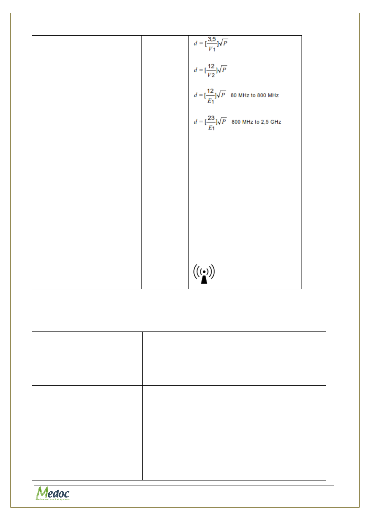
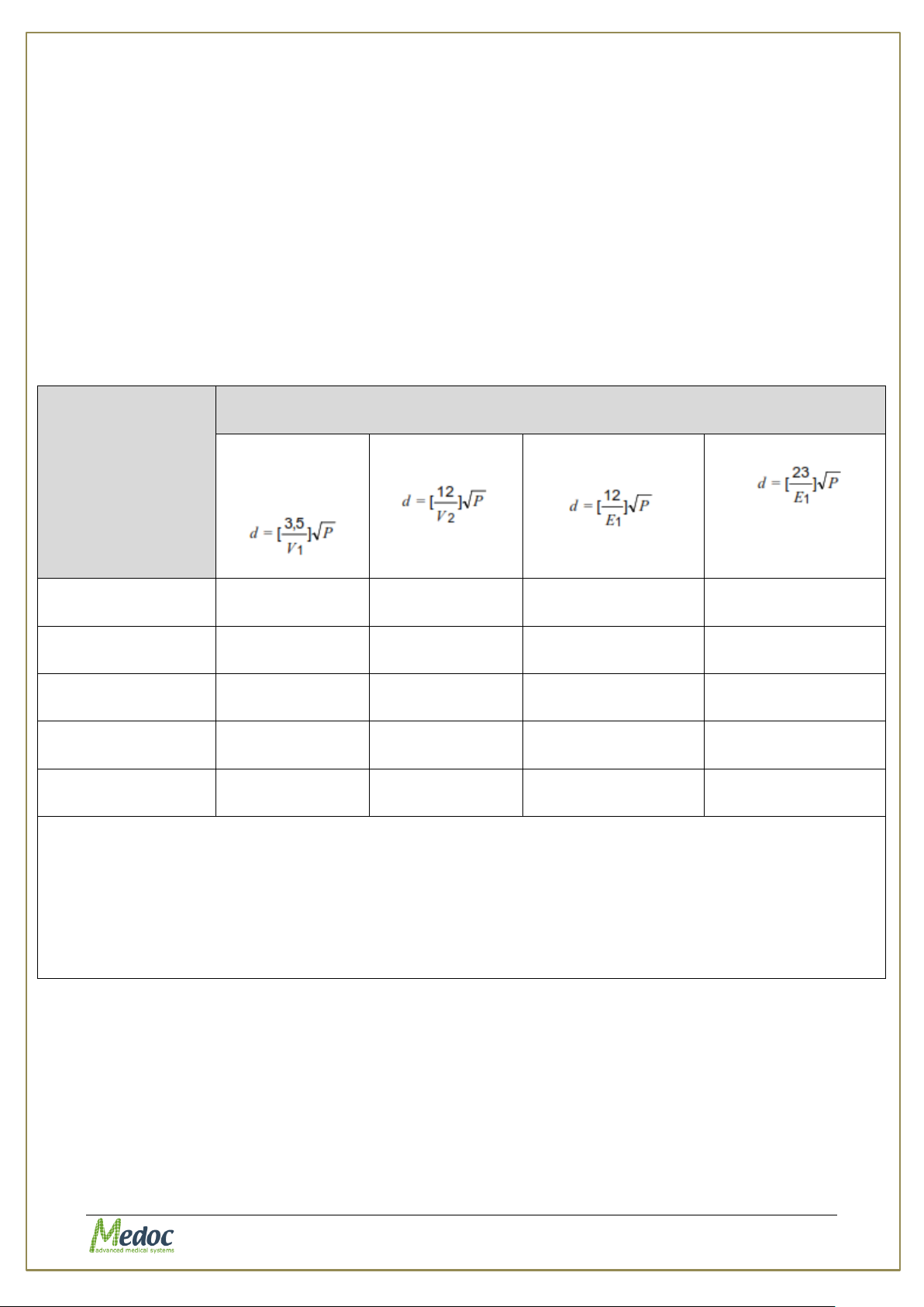
where P is the maximum output
power rating of the transmitter in
watts (W) according to the
transmitter manufacturer and d is
the recommended separation
distance in metres (m).
Field strengths from fixed RF
transmitters, as determined by an
electromagnetic site survey,
should be less than the
compliance level in each
frequency range.
D Interference may occur in the
vicinity of equipment marked with
the following symbol:
Declaration – electromagnetic emissions
Emissions
test
Compliance
Electromagnetic environment – guidance
RF emissions
CISPR 11
Group1 Class A
The Algomed uses RF energy only for its internal
function. Therefore, its RF emissions are very low and
are not likely to cause any interference in nearby
electronic equipment.
Harmonic
emissions
IEC
61000-3-2
Class A
The Algomed is suitable for use in all establishments
other than domestic, and may be used in domestic
establishments and those directly connected to the
public low-voltage power supply network that supplies
buildings used for domestic purposes, provided the
following warning is heeded: Warning: This
equipment/system is intended for use by healthcare
professionals only. This equipment/ system may cause
radio interference or may disrupt the operation of
nearby equipment. It may be necessary to take
mitigation measures, such as re-orienting or relocating
the Algomed or shielding the location.
Voltage
Fluctuations
And Flicker
IEC 61000-33:2013
Complies
Proprietary 15 of 110
Page 16
AlgoMed Technical Reference Manual
Rated maximum
output power of
transmitter
(W)
Separation distance according to frequency of transmitter (m)
150 kHz to 80 MHz
outside ISM
bands
150 kHz to 80 MHz
in ISM bands
80 MHz to 800 MHz
800 MHz to 2,5 GHz
0.01
0.12
0.2
0.4
1
0.1
0.37
0.64
1.3
2.6
1
1.17 2 4 8 10
3.7
6.4
13
26
100
11.7
20
40
80
For transmitters rated at a maximum output power not listed above, the recommended separation
distance d in metres (m) can be estimated using the equation applicable to the frequency of the
transmitter, where P is the maximum output power rating of the transmitter in watts (W) according to the
transmitter manufacturer.
NOTE 1: At 80 MHz and 800 MHz, the separation distance for the higher frequency range applies.
NOTE 2: These guidelines may not apply in all situations. Electromagnetic propagation is affected by
absorption and reflection from structures, objects and people.
1.8 Recommended Separation Distance between portable
and mobile RF communications equipment and AlgoMed
The AlgoMed is intended for use in an electromagnetic environment in which radiated RF
disturbances are controlled. The customer or the user of the AlgoMed can help prevent
electromagnetic interference by maintaining a minimum distance between portable and mobile
RF communications equipment (transmitters) and the AlgoMed as recommended below,
according to the maximum output power of the communications equipment.
Proprietary 16 of 110
Page 17
AlgoMed Technical Reference Manual
Medoc reserve the right to change specification without prior notice, in
line with the company policy of constant product improvements
Some of the specifications require specific license / hardware which are
not available in the standard configuration.
Parameter
Specification
Load Cell FPIX 50
50 lbf / 25 kgf
Accuracy
±3% of reading
Display
160 x 100 Graphic LCD
Reversible White Backlight
Selectable Brightness and Contrast
Display Update
8 per second
Power
USB connection
Rechargeable 9V NIMH battery
Battery Endurance
Up to 4 hours with backlight on high
Up to 20 hours with backlight off
Battery Charge
12 hours for typical charge (21 hours for full
charge)
Tip Size
1 cm
2
Communication with computer
USB
Calibration Verification Weight
1 Kg Weight
Used to verify device accuracy
Calibration Certificate
NIST calibration certificate of the unit
Calibration
Auto calibration
Internal Memory
500 Data Point Memory
Load Cell
Interchangeable load cell
Patient Response
USB Patient Response unit to record patient
response during stimulation
Safety
Complies with UL-2601-1:94 and EN-606011-1
Unit Weight
0.4 Kg (Shipping weight 2.5Kg)
Dimensions
70mm x 100mm x 30mm (w x h x d)
Ambient temperature
18 to 24ºC
Product life time
10 years
1.9 Technical Data
Table 2: AlgoMed Specifications
Proprietary 17 of 110
Page 18
AlgoMed Technical Reference Manual
Please note that the above specifications are correct only for the new
model of Algomed which are manufactured from 2015 and on. See in
below table the specifications differences.
Parameter
specifications for Algomed
manufactured before 2015
specifications for Algomed
manufactured from 2015
Display
5 digit, 0.5” LCD
160 x 100 Graphic LCD
Reversible White Backlight
Selectable Brightness and Contrast
Power
110 or 220 VAC charger-
Rechargeable 7.2V NIMH battery
USB connection
Rechargeable 9V NIMH battery
Battery Endurance
Up to 20 hours
Up to 4 hours with backlight on
high
Up to 20 hours with backlight off
Battery Charge
10 hours for full charge
12 hours for typical charge (21
hours for full charge)
Table 3: Algomed model specifications differences
Proprietary 18 of 110
Page 19
AlgoMed Technical Reference Manual
2. Overview
The AlgoMed Computerized Pressure Algometer is an advanced computerized pressure
stimulator, designed for clinical use, and research in the field of pain management.
The AlgoMed system enables the user to perform various pressure test paradigms including
the Methods of Limits, and Ramp and Hold. These test paradigms can be utilized for a wide
range of pressure pain measures such as pressure pain threshold and tolerance, temporal
summation, conditioned pain modulation and others.
The Medoc Main Station software package introduces new standards and capabilities into pain
management and pain research. The software includes an SQL data base to allow complete
Patient, Program and Results management. The user friendly interface simplifies test
management and provides real-time visual and auditory feedback. Results can be displayed in
color customizable reports or exported to MS Excel for further analysis.
AlgoMed can be utilized as a standalone unit or as an accessory to the Medoc PATHWAY
system.
2.1 AlgoMed Computerized Pressure Algometer
The AlgoMed Computerized Pressure Algometer provides pain diagnostic testing with digital
clarity and computer interface for data logging.
Pressure algometry is a reliable measure of pain in muscle, joints, tendons, and ligaments. The
AlgoMed proves the benefits of applied medication, physiotherapy or manipulation.
As treatment progresses, the AlgoMed quantifies improvements or setbacks.
Pain threshold measurements provide unique information not obtainable by any other method.
The objective measurements give reassurance to patients by confirming improvement.
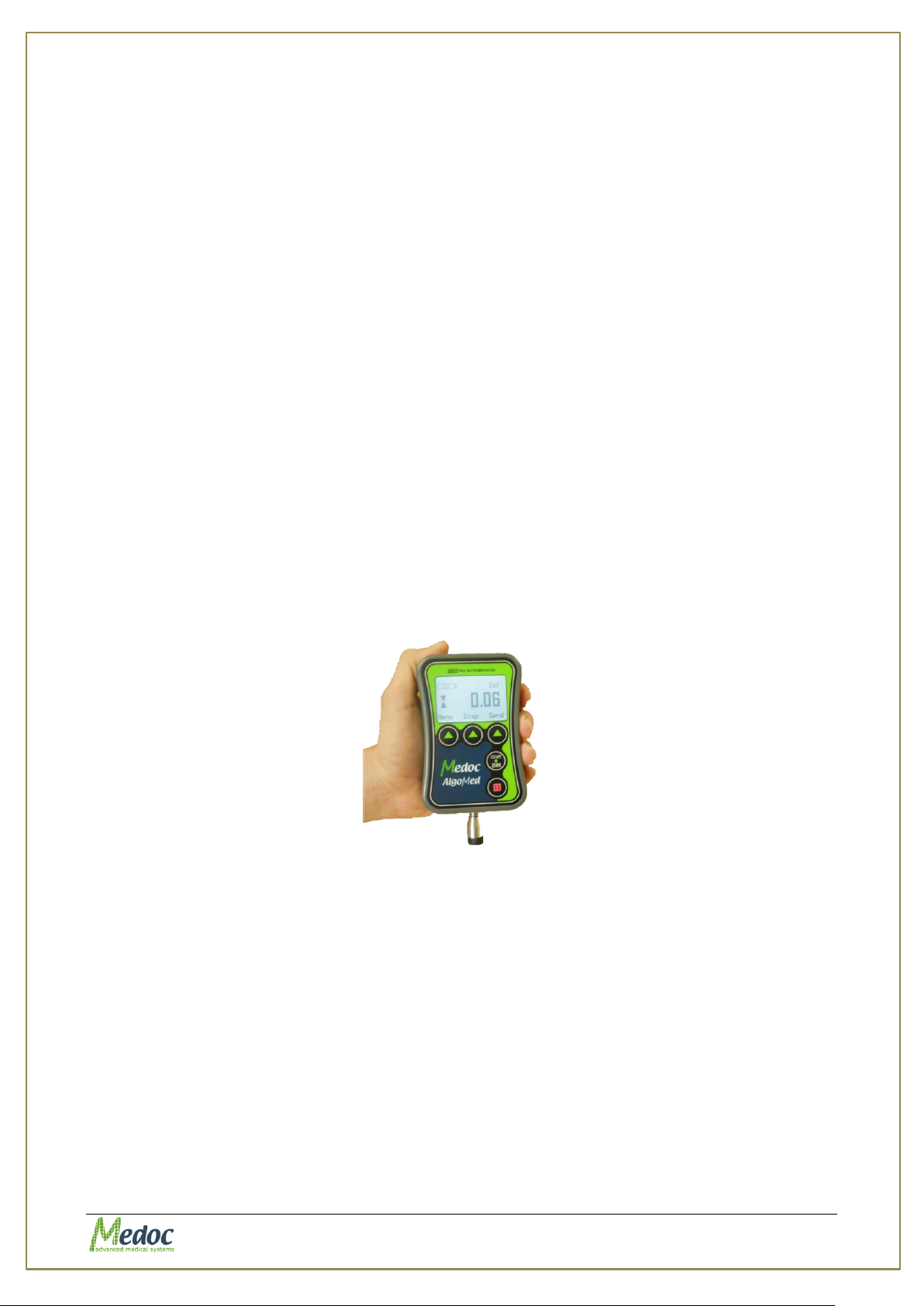
Figure 2: AlgoMed Computerized Pressure Algometer
2.2 System Status
Connected: This is the AlgoMed system full mode of operation and indicates full
communication between Medoc Main Station and the Algometer.
Not Connected: This is a demo mode of operation. The Algometer is not connected to
Medoc Main Station and it is not possible to perform any tests. Patient records,
programs and results can still be accessed.
2.3 Application Methods
The Method defines the type of protocol used for the test. The following methods are
supported:
Limits: A set of stimuli at a predetermined rate is given, and for each stimulus, the
subject is required to stop the stimulus when the required sensation is perceived.
Proprietary 19 of 110
Page 20

AlgoMed Technical Reference Manual
Ramp & Hold: The Pressure applied by the operator is given according to preset
parameters such as: pressure increase rate, destination, duration at destination
pressure and etc.
2.3.1 Limits Method
This reaction time inclusive method consists of stimuli of continuously changing intensity. With
each stimulus, when the subject perceives a predefined sensation, he/she notify the operator
who stops the stimulus.
The Limits method is the most widely used method for threshold and tolerance determination,
because it requires the shortest test procedure of all methods.
See section 7.3.1.1, page 50, for full description of program details and parameters.
2.3.1.1 Pain Threshold
Pain Threshold can be defined as the minimum pressure that induces pain in tender and
trigger points of tissue. The AlgoMed quantitatively assesses the tenderness of hypersensitive
areas. The AlgoMed, used for pain threshold testing, is appropriate for determining the
minimum pressure that triggers pain at the point of interest.
2.3.1.2 Pain Tolerance
Pain Tolerance can be defined as the point where painful pressure stimulus cannot be
tolerated. The AlgoMed assesses pain sensitivity for maximum tolerated pressure. AlgoMed is
used for pain tolerance testing; its wider range necessary for comparative tests between a
normal sensitivity control point and the area of interest.
2.3.2 Ramp and Hold Method
The ramp and hold method is a configurable method enabling the user to design a wide range
of pressure stimuli patterns which can be utilized for various applications such as temporal
summation and DNIC.
Proprietary 20 of 110
Page 21
AlgoMed Technical Reference Manual
Installation USB
Calibration
USB Patient
Response Unit
Algometer
USB
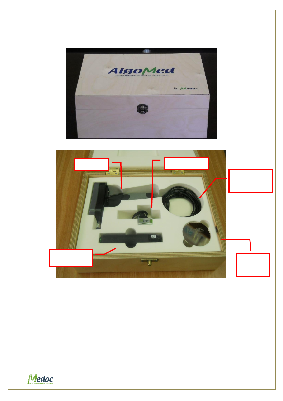
3. System Components
The system is packed in a case that includes all of the AlgoMed components.
Figure 3: AlgoMed Case
comminucation
cable
Verification
Weight
Figure 4: AlgoMed Case
Proprietary 21 of 110
Page 22
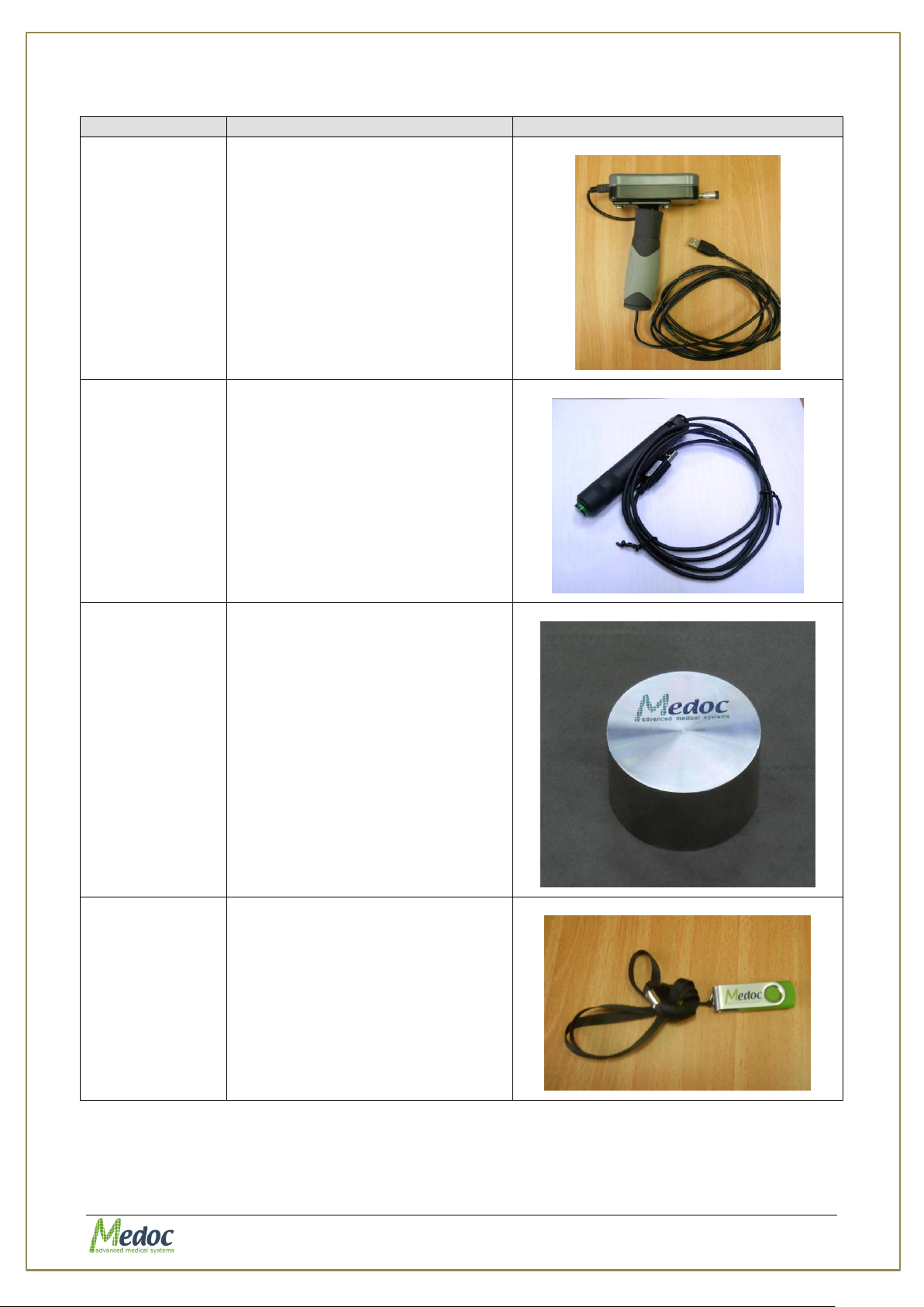
AlgoMed Technical Reference Manual
Component
Description
Picture
Algometer
FPIX 50
The AlgoMed Algometer with
maximum capacity of 50 lbf.
Include rubber hand grip and a
communication cable.
USB Patient
Response Unit
Response Unit that is used to
record tested subject response
Calibration
Verification
Weight
Weight which can be used to
verify Algometer Calibration
Installation
USB
Contain AlgoMed installation files,
manuals and recovery tools
Table 4: AlgoMed system components
Proprietary 22 of 110
Page 23
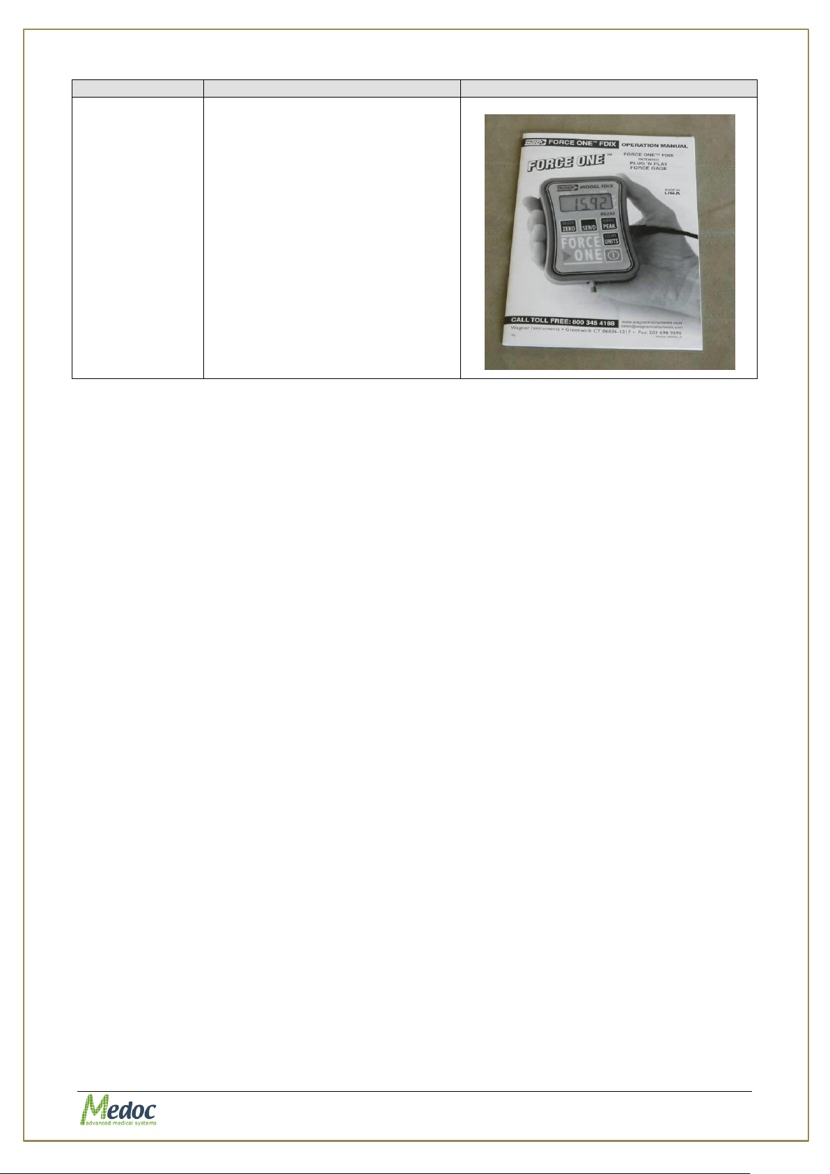
AlgoMed Technical Reference Manual
Component
Description
Picture
AlgoMed FPIX
Operating
Manual
Describe how the AlgoMed FPIX
algometer can be used without
the AlgoMed software package
Proprietary 23 of 110
Page 24
AlgoMed Technical Reference Manual
Complete and verify the entire AlgoMed setup and installation process
before using the system.
Safety
Computer must comply with IEC 950 – EN 60950 – UL 60950
Processor
Intel Core i3 4xxx or better
(avoid low power processors such as Atom, Pentium or Celeron)
Memory
4 GB RAM
Storage
128 GB
USB slots
2 free USB slots (3 for AlgoMed and Q-Sense CPM)
Monitor/Display
13’’ (15’’ recommended)
Screen
Resolution
1366 x 768 pixels, 96 DPI (max. 1920x1080)
Operating
System
Windows 7, 8, 10 32/64 bit
(Not recommended: Windows XP service pack 3. Please see note below)
Other
Microsoft Office 2007 or above (required for viewing results in excel)
The following Medoc Main Station updates will no longer support Windows
XP. Please avoid using Windows XP operating system if possible.
The computer used for Medoc Main Station software should be dedicated
for this purpose only. Medoc takes no responsibility for any conflicts which
may occur with other programs
For optimal performance disable any other resource heavy programs
running on the same computer such as Anti-Virus, Screen Saver, Hibernate
Mode, and Network connections.
4. Setup and Installation
The AlgoMed system installation is designed to be simple and fast. Follow the instructions
given below for selecting a location, installing and initial. Proper installation and operation of
the equipment is important for ensuring the safety of the tested subjects.
4.1 Computer Requirements
The requirements below are minimum requirements intended to be used as a guideline for
selecting a computer to use with Medoc Main Station software.
Proprietary 24 of 110
Page 25
AlgoMed Technical Reference Manual
The installation USB contains all of the unique system files. Keep it in a
safe place. It may be required for restoring the system configuration in
case of malfunction and/or service during remote control session by
Medoc.
Refer to the preceding chapters for further details on the system
components
Different type of walls requires different masonry anchors.
4.2 Installation USB Content
The installation USB contains the MEDOC Main Station setup program and additional features
that are required for system normal operation, as detailed below:
1. MEDOC Main Station setup program.
2. Software license files.
3. Technical Reference Manual.
4. Technical Reference Service Manual.
5. Remote assistance tools.
4.3 Installation Main Steps
The assembly procedure consists of the following steps:
1. Selecting a location for the system. See section 4.4, page 25.
2. Connecting the various connections and devices to the system.
3. Connecting the laptop and installing the MEDOC Main Station software. See section 4.4,
page 25.
4. Configuring the system.
4.4 Selecting a Location
An appropriate location for the AlgoMed system should meet the following criteria:
1. The room temperature should be kept between 18°C and 24°C.
2. The AlgoMed system should not be placed in a location, which is exposed to direct sunlight,
constant vibrations, or close to heaters or air conditioners.
3. The room in which the system will be located should be quiet, allowing the subject to
concentrate on the examination with minimum distractions.
4.5 Software Installation
The installation procedure of MEDOC Main Station software can only be performed by a user
with windows system administrator rights. Without appropriate access rights, the installation
procedure may fail.
Users with previously installed versions of Medoc Main Station should review the upgrade
instructions before proceeding.
Proprietary 25 of 110
Page 26
AlgoMed Technical Reference Manual
Depending on the current configuration of the computer, MEDOC Main
Station installer may require the installation of additional components. The
installation procedure may take several minutes.
Software installation can be performed only by Windows System
Administrators only
Disable any antivirus that runs on the PC before installing Medoc Main
Station.
Keep all liquids away from the AlgoMed system.
Turn off the AlgoMed device if it is not to be used for a long period of
time.
When all setup and installation procedures have been completed you can
start using the system in accordance with the operation instructions in
section 5
The following instructions will guide you through the installation procedure:
1. Insert the USB drive into an available USB port on the computer
2. Open the folder to view files.
3. Double-click Setup.exe to start software installation
4. Click Next to continue the installation.
5. Select the file location where Medoc Main Station should be installed. You can use the
location recommended by the installation. Click Next to continue.
6. Select the location of the Medoc Main Station shortcuts in the start menu. You can use the
location recommended by the installation. Click Next to continue.
7. Installing normative data – please read the agreement carefully. If you agree to the term
please choose to install normative data. Click Next to continue.
8. Privacy – please read the terms carefully. If you agree please choose to allow data
collection. You may cancel this option any time later if you choose to.
9. The installation is now in progress. Depending on your computer configuration it may take
up to several minutes.
10. After installation has completed, click Finish to close the wizard.
11. Restart your Computer.
12. Medoc Main Station software is now ready to be used.
4.6 Unit Protection
4.7 Product Activation
When starting Medoc Main Station software for the first time, you will be asked to register your
new system and activate the software. Product registration and software activation is simple
and fast and it will enable you to maintain full use of Medoc Main Station software as well as:
Warranty on your newly purchased Medoc systems
Proprietary 26 of 110
Page 27
AlgoMed Technical Reference Manual
Home screen product registration link
Access to Technical Support and Customer Service assistance
Software updates and new product notifications
Product support alerts
Please note that if you don’t activate the software within the designated time, the software will
work in demo mode only.
To complete the activation process, simply start Medoc Main Station software and follow the
instructions given in the activation wizard. If the activation wizard is not displayed when you
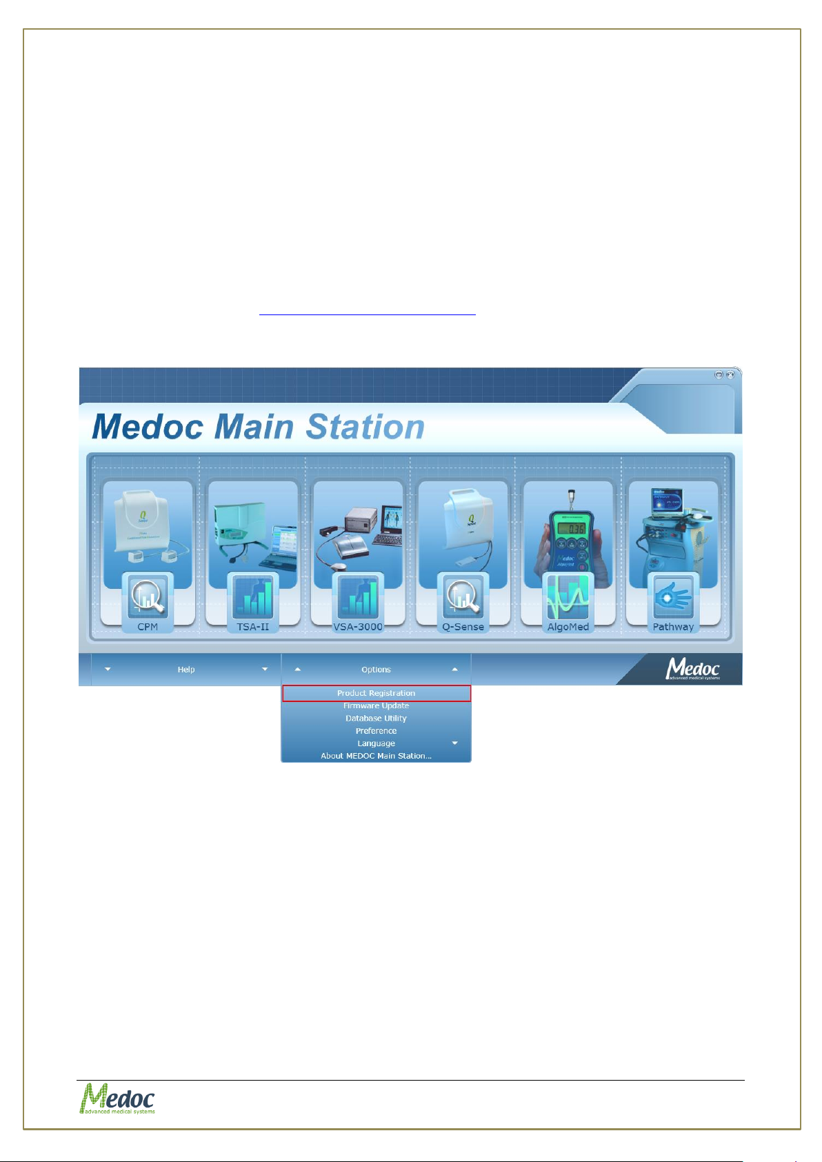
start Medoc Main station Software, go to the Home screen, select Options and then select
Product Registration. See Figure 5 below.
If at any point during the product activation process you encounter any difficulties please
contact Medoc support at [email protected] for assistance.
Figure 5: Home screen product registration link
Proprietary 27 of 110
Page 28
AlgoMed Technical Reference Manual
Do NOT Connect the AlgoMed computer to a network while performing
tests with the system!
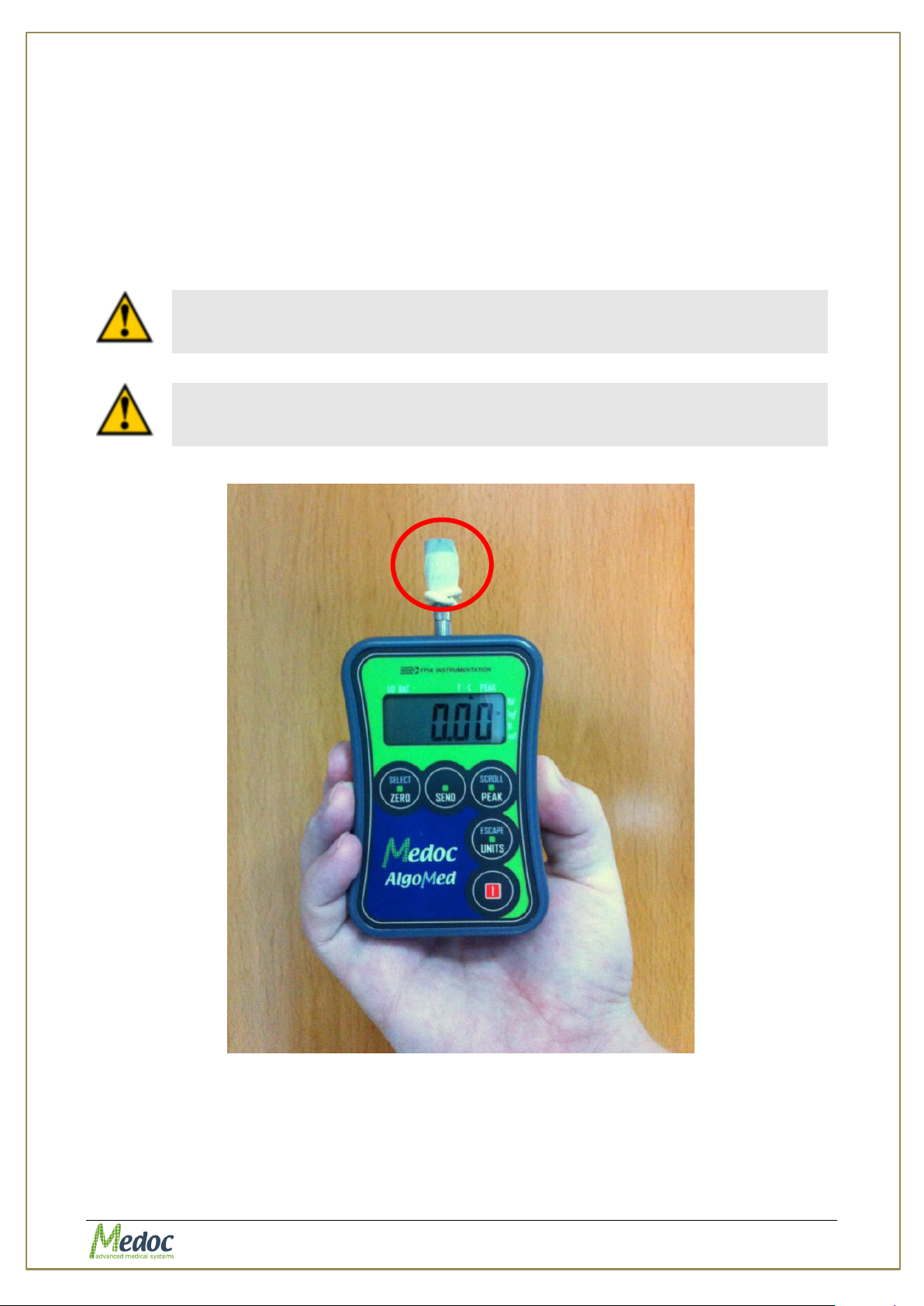
Before each patient wrap the AlgoMed tip with standard disposable
biocompatible finger cot (Figure 6)
5. Operation
The purpose of the following chapters is to specify the AlgoMed applications and to bring indetail step-by-step instructions for using the system.
This chapter specifies AlgoMed behavior at start up, and MEDOC Main Station basic
components.
5.1 Safety
Figure 6: Warping the tip
Proprietary 28 of 110
Page 29
AlgoMed Technical Reference Manual
Connect the AlgoMed USB Cable to the computer
The AlgoMed software is named MEDOC Main Station and is indicated by
the icon on your desktop.
5.2 Starting the AlgoMed System
1. Connect the AlgoMed USB cable to the computer
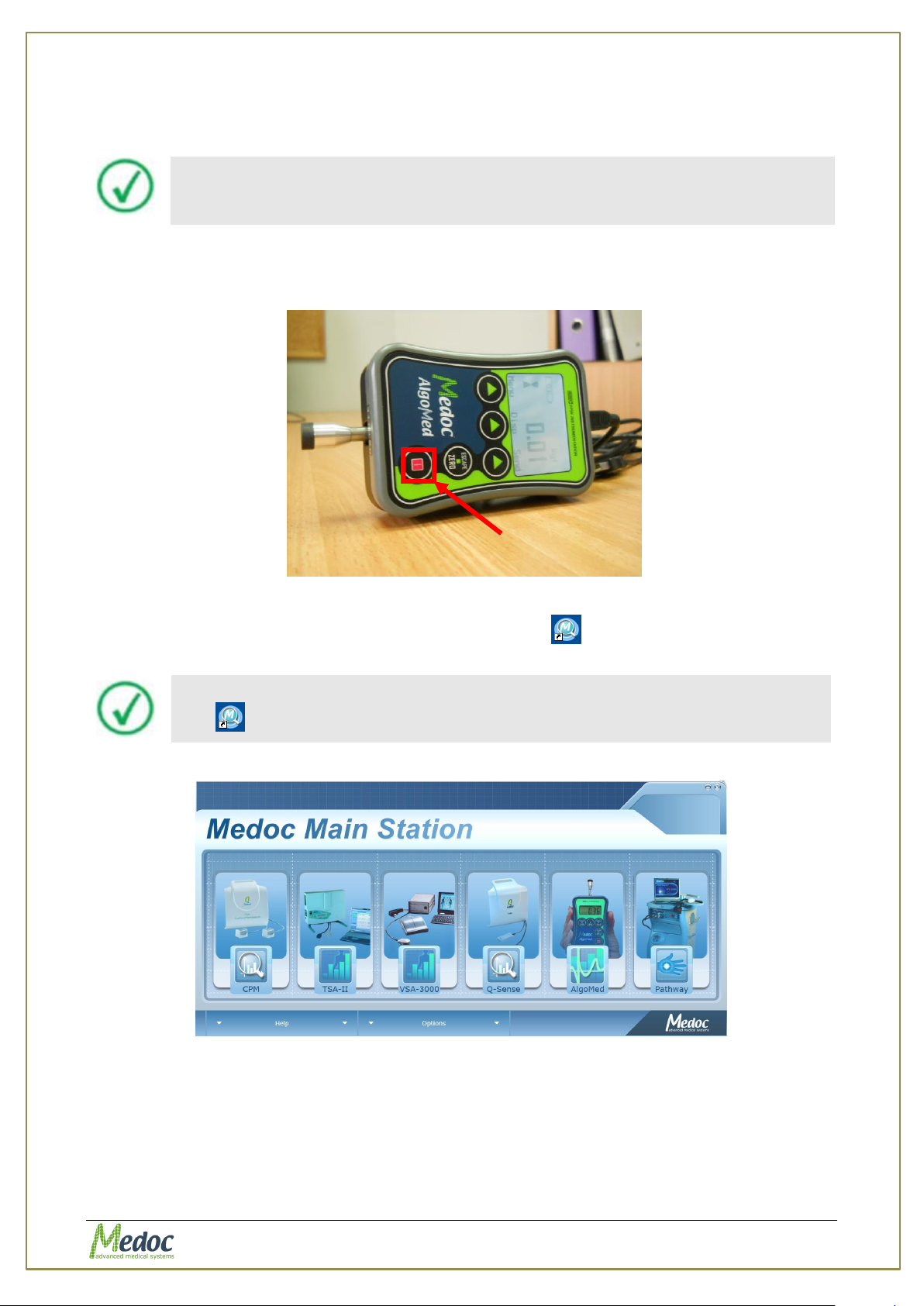
2. Turn on the AlgoMed device with the ON/OFF button.
Figure 7: AlgoMed On / OFF button
3. Start the AlgoMed Software by double clicking the icon . The welcome screen is
displayed.
Upon launching MEDOC Main Station, the following image is displayed:
Figure 8: Device selection Screen
The screen displays Medoc Main Station devices. Choose AlgoMed.
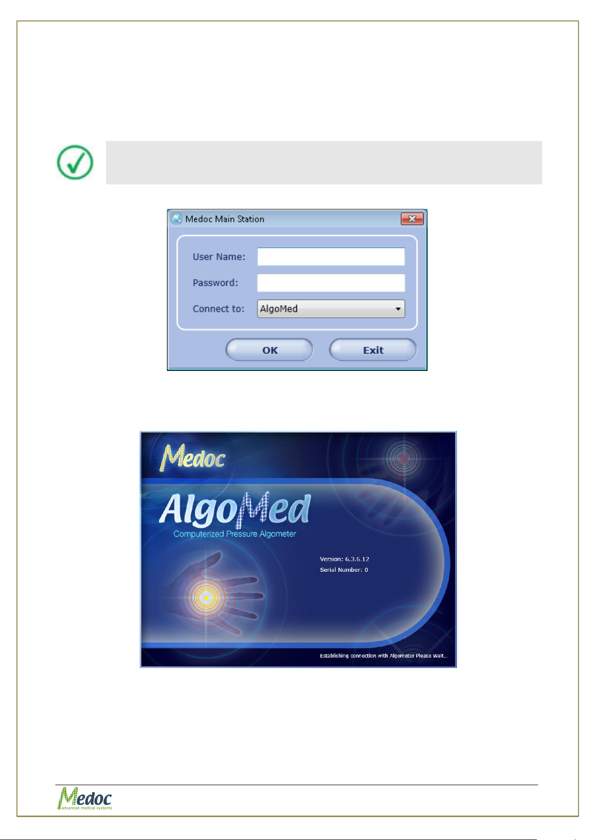
1. When the login screen is displayed, enter your user name and password and select a
connection option as described below; then click OK
1.1. The default user credentials are:
Username: admin
Proprietary 29 of 110
Page 30
AlgoMed Technical Reference Manual
Initial login Username and Password are both admin.
For more information on user management please refer to section 10.1.6
Password: admin
1.2. The available connections depend on your license agreement and purchased
devices.
Not Connected – software will start without connecting to any device
AlgoMed – software will establish communication with AlgoMed.
Figure 9: Login Screen
2. Software will attempt to establish communication with AlgoMed system.
the following screen is than displayed while the software is loading:
Figure 10: Welcome Screen
4. The software will check user authentication and start with TEST mode screen.
5. If communication was established successfully continue to section 5.4, page 32. Otherwise,
if you selected Not Connected continue to the next section in order to manually connect
the AlgoMed.
Proprietary 30 of 110
Page 31
AlgoMed Technical Reference Manual
5.3 Connecting to the AlgoMed Manually
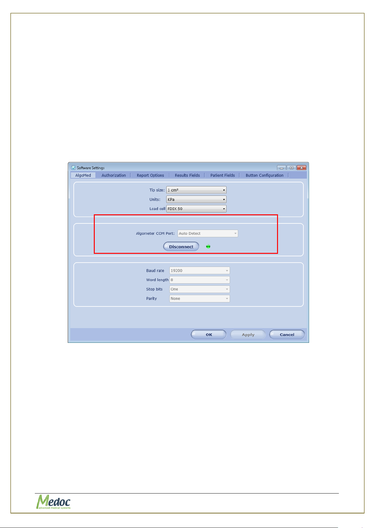
Medoc Main Station automatically connects to the AlgoMed device during startup. In case
software was started in the offline mode (“not connected” option was selected during software
login) or communication was disconnected accidently it is possible to reconnect from within the
software. To connect to the AlgoMed device follow the instructions below:
1. Select Settings from the top menu bar.
2. Select Software Settings from the settings sub-menu.
3. Select AlgoMed tab.
4. Select the specific COM port from the AlgoMed COM Port drop-down menu or select
Auto Detect. See Figure below.
5. Click Connect and wait for the indicator on the side to turn GREEN.
6. Press OK. AlgoMed Algometer is now connected and ready for use.
Figure 11: Connecting to the AlgoMed
Proprietary 31 of 110
Page 32
AlgoMed Technical Reference Manual
Menu
Option
Description
File
Export
Export selected Patient data, Program parameters or
Test Results to *.ats file format.
The *.ats file format is encoded and can be read only by
MEDOC software, enabling simple backup, export and import
option while maintaining patient confidentiality.
Import
Import Patients, programs and test results saved in *.ats
file format. See above description on Export.
Export to
Excel
Export Tests Results to MS Excel format, for data analysis.
Print
Print Test Results as a Report (enabled in the Results
screen). Refer to section 9.3 for further information.
Logoff
Log off and switch users without exiting the software
Switch device
Allows the user to switch between other MEDOC devices.
Exit
Exit MEDOC Main Station.
View
Test
Switch to Test Editor screen to perform and manage tests
from the available patient and program library.
Patients
Switch to Patient Editor screen for managing Patient lists.
Menu Bar
Toolbar
Data Display
Search Row
Current
Test
Status Line
5.4 Basic Operation – Terminology
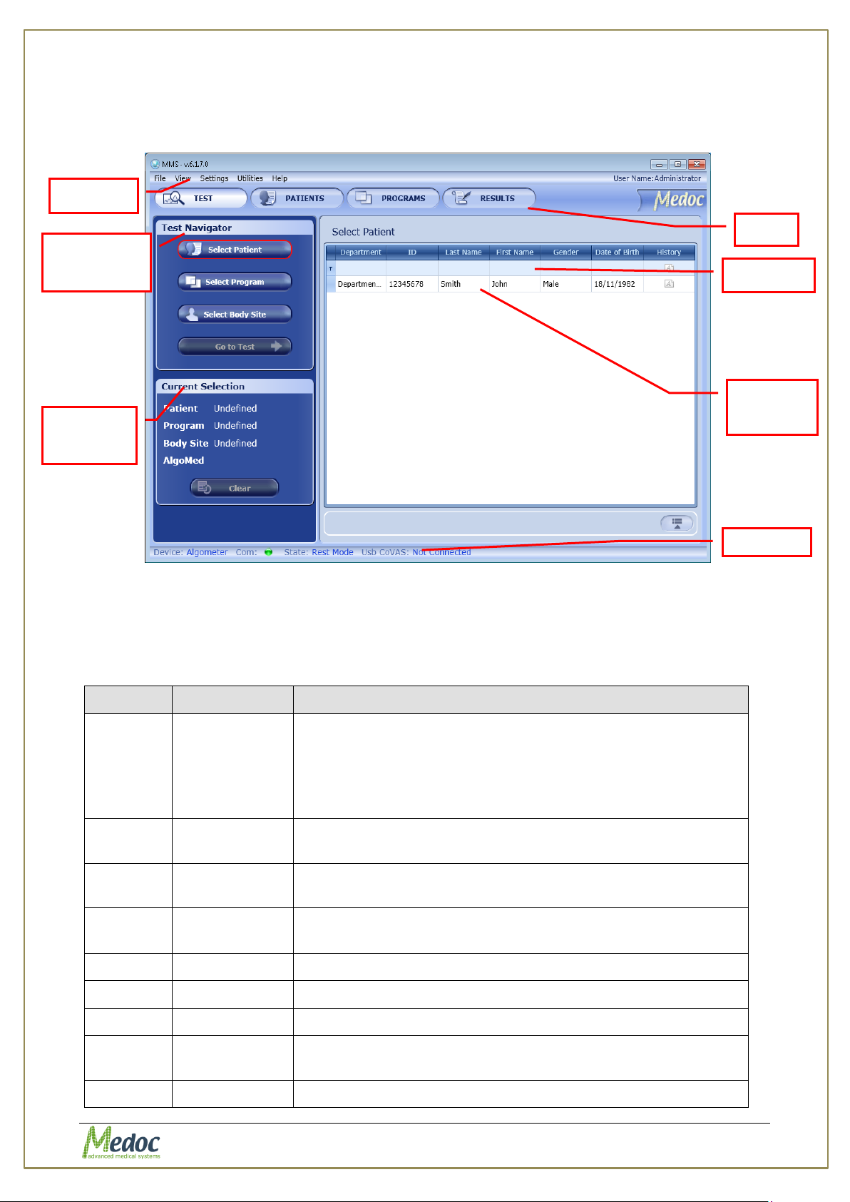
The following section describes the main components of MEDOC Main Station display:
Navigation
Selections
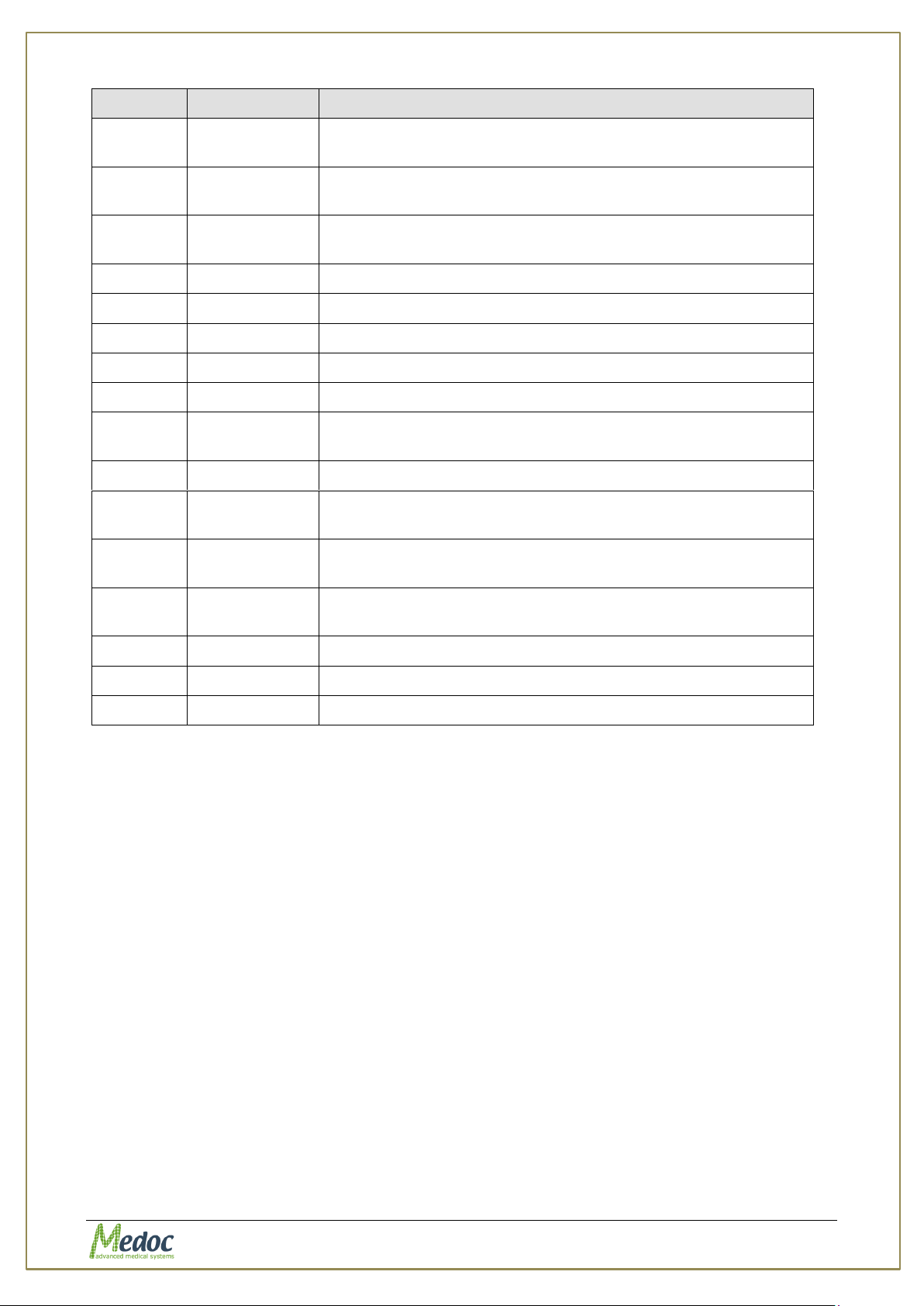
Figure 12: TEST Sceen - Main Menu
5.4.1 Menu Bar
The Menu bar consists of the following options:
Table 5: Menu Bar options
Proprietary 32 of 110
Page 33
AlgoMed Technical Reference Manual
Menu
Option
Description
Programs
Switch to Program Editor screen for managing programs and
protocols.
Results
Switch to Results screen to view and manage saved test
results.
Settings
Software
settings
MEDOC software related configuration and preferences.
Test settings
Test configuration and display preferences
Status
Allows to switch between on-line or off-line mode
Utilities
Department
Manage Department list
ICD 9
Manage list of ICD 9 codes
Log Files
Software log files
Normative
Data
Normative Data database and Editor.
Black box
System logs (populated only in case of suspected error)
Device
Recovery
Manually initiate PATHWAY system self-test in case safety
was triggered.
Help
Operating
Manual
Link to the AlgoMed Operating Manual digital file.
Service
Manual
Link to the AlgoMed Service Manual digital file.
About …
System and software information
Service Call
Submit a Service Call via Medoc web site*.
FAQ
FAQ on Medoc web site*.
5.4.2 Toolbar
The Toolbar consists of shortcuts to five items in the menu bar:
Test
Patients
Programs
Results
Exit
See the table above for a short description.
5.4.3 Search Row
The Search Row allows you to filter the displayed data, in order to find the required data
quickly. The following options are available:
1. Filter data
2. Last selection
3. Auto complete
4. Custom search
Proprietary 33 of 110
Page 34

AlgoMed Technical Reference Manual
5.4.4 Current Selection Information
Displays the current selection made by the AlgoMed user. Current selection information may
vary according to the displayed screen.
5.4.5 Data Display Area
Displays list of data which is relevant to the current screen.
5.4.6 Status Line
Display the Algometer status and state.
Proprietary 34 of 110
Page 35
AlgoMed Technical Reference Manual
Before starting a test, make sure that you are familiar with the stimulation
method.
Inform the subjects how to operate the applicable controls, and request
them to concentrate on the perceived sensations throughout the entire
test.
Do not press on the Algomed device Disp button during a test.
6. Test Management
Performing a test procedure is possible from the Test screen only.
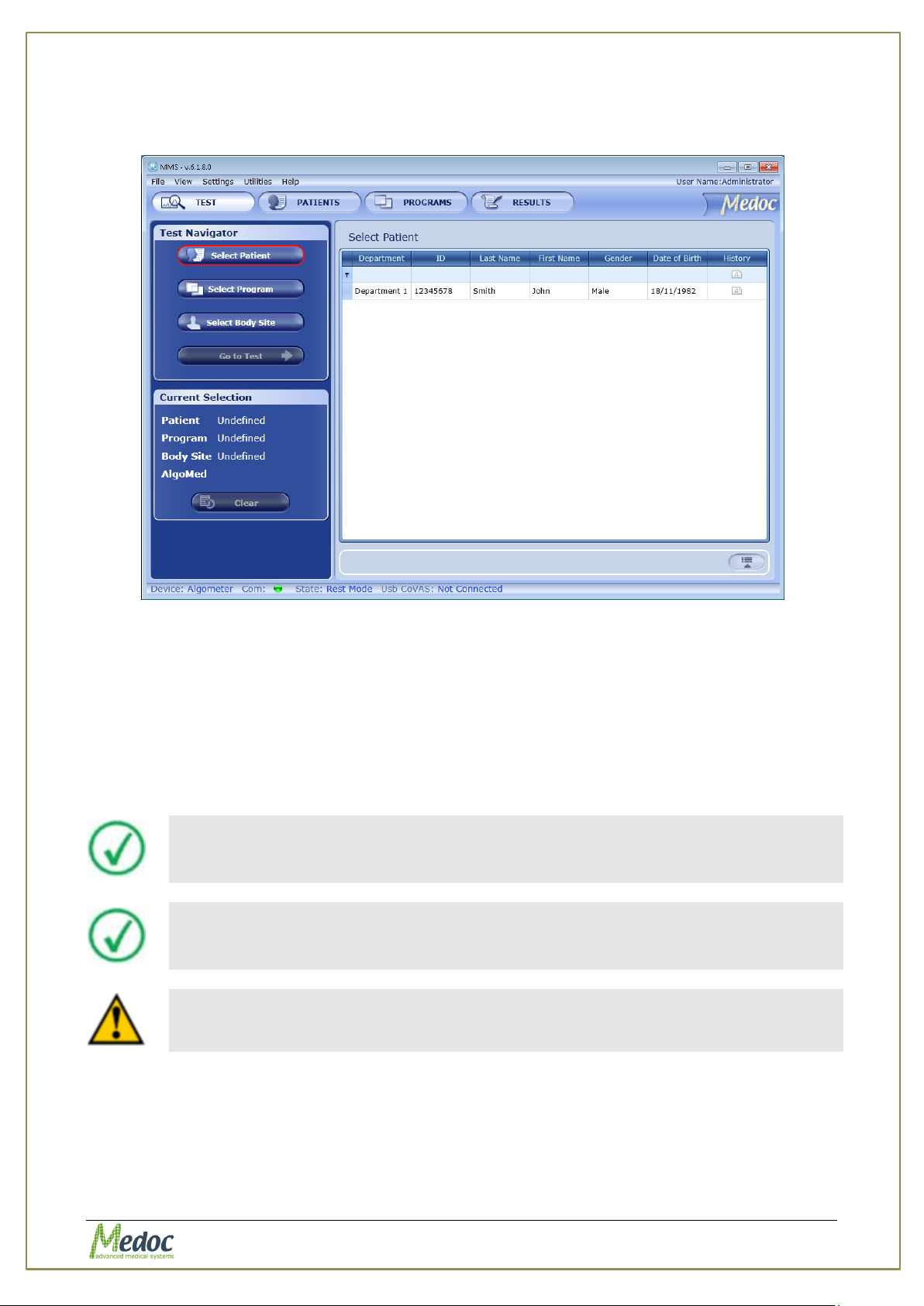
Figure 13: Test Management Main Screen
The stimulation procedure (test) is divided into the following sections:
Select Patient – Selection of the tested subject’s file from the database.
Select Program – Selection of the relevant program that will be used for the test.
Select Body Site – Selection of the body site and its details for the current test. This
step is optional.
Stimuli Administration – The process of delivering the stimulation and saving the
stimulation data. This section includes the subject’s name and pressure/time values.
6.1 Selecting a Patient
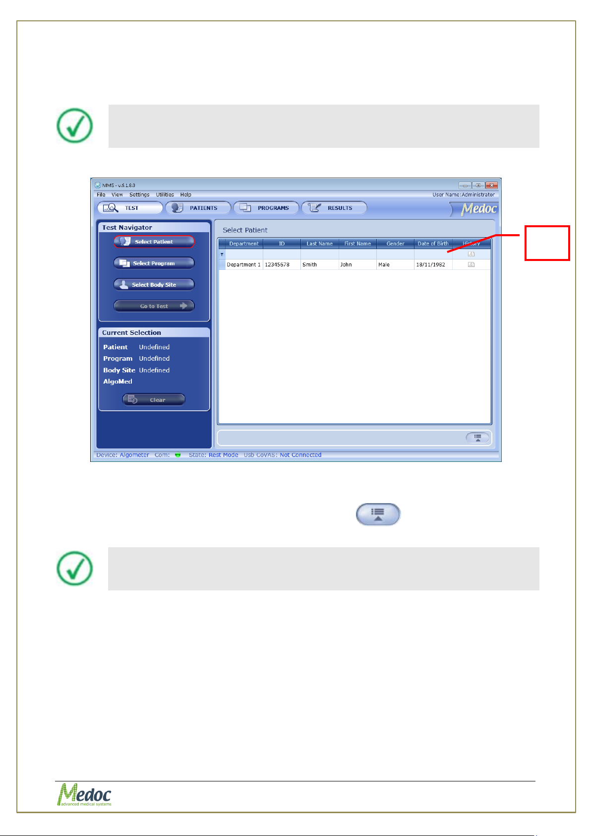
1. The AlgoMed software enables you to filter the patients list according to various criteria:
Department, First Name, Last Name, ID, and Date of Birth.
a. Use the filter row at the top of the patients list, in order to filter the list.
Proprietary 35 of 110
Page 36
AlgoMed Technical Reference Manual
The more criteria you define using the filter, the shorter the list that will
be displayed.
Patient details can only be viewed from the Test screen. For editing, refer
to Patient Management section (section 8, page 57).
Filter
Row
b. Use the drop down list at the top of each column to refine and narrow your
selection.
c. Auto complete of existing names is active.
d. To clear the filtered list, select the (All) option from the filter drop down list.
Figure 14: Patient Selection Menu
2. In order to select a patient, click on the patient entry and then press the Select button.
3. In order to view patient details, click the Open Details button or double-click the
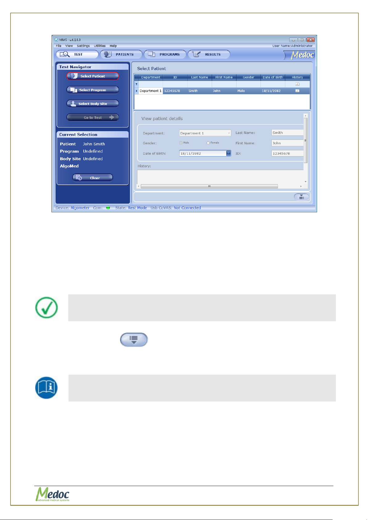
Patient entry (for editing patient details, refer to section 8.4, page 60).
a. The Patient Details preview is displayed:
Proprietary 36 of 110
Page 37
AlgoMed Technical Reference Manual
The patients list can be sorted according to any of the column headers.
Click the required column header to sort the list.
It is not possible to run a test before you select the tested subject and the
program. The “Go to Test” button will remain disabled as long as test
details are not complete.
Figure 15: Patient Details Screen
The following fields are displayed by default:
o Department: The Hospital Department.
o Last Name
o First Name
o ID Number
o Date of Birth
4. Click the Hide Details button to view the patients list only.
5. Click the Clear button to clear Current Test information if required.
6. Proceed to the Selecting a Program section.
Proprietary 37 of 110
Page 38
AlgoMed Technical Reference Manual
The more criteria you define using the filter, the shorter the list that will
be displayed.
Program details can only be viewed from the Test screen. For editing, refer
to Program Management section (section 7, page 47).
Filter
Row
6.2 Selecting a Program
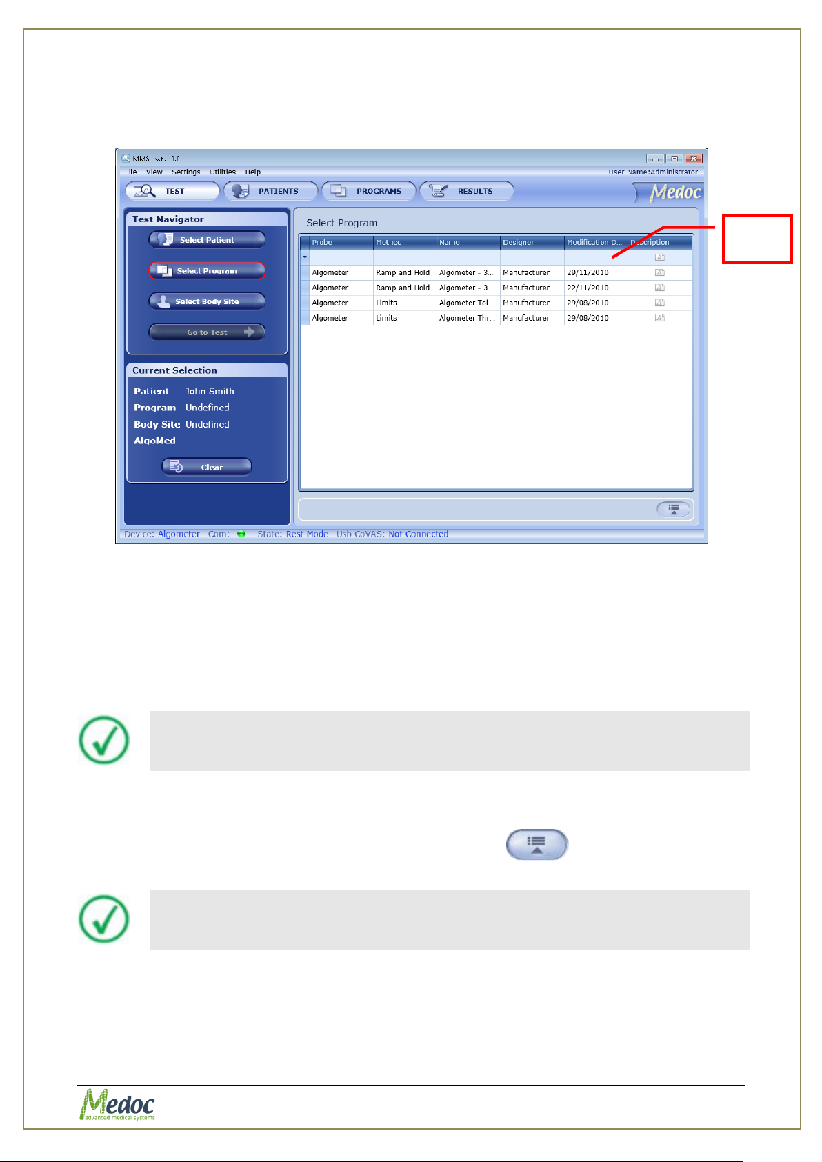
1. Click on the Select Program button.
The Programs List screen is displayed:
Figure 16: Programs List
2. The AlgoMed software enables you to filter the program list according to various criteria:
Probe, Method, Program Name, Designer, Description and Updated On date.
a. Use the filter row at the top of the programs list in order to filter the list.
b. Use the drop down list at the top of each column to refine and narrow your
selection.
c. Auto complete of existing names is active.
d. To clear the filtered list, select the (All) option from the filter drop down list.
3. In order to select a program, click on the program entry and then press the Select button.
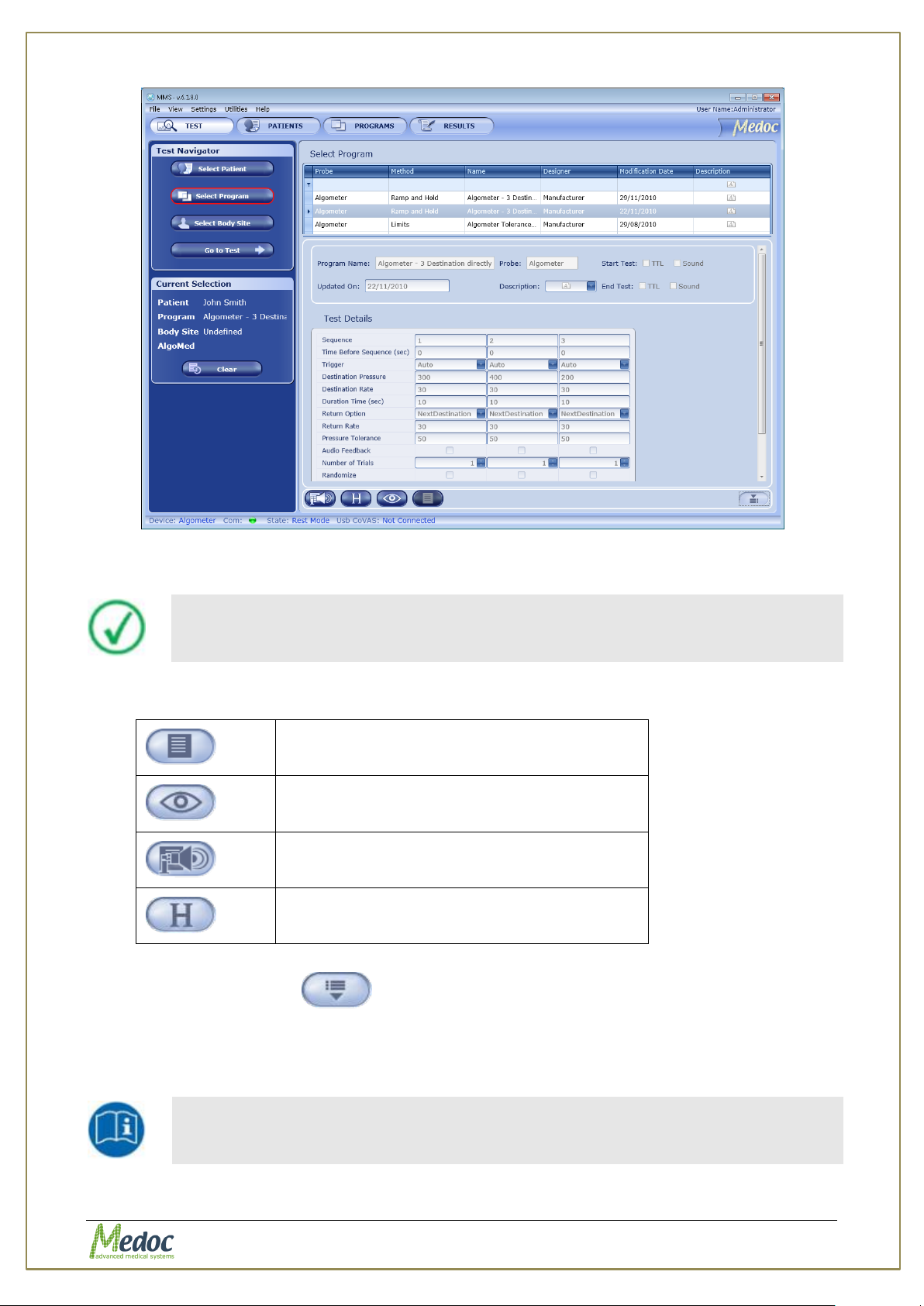
4. In order to view program details, click the Open Details button or double-click
the Program entry (for editing program details, refer to section 7.7, page 56).
a. The Patient Details preview is displayed:
Proprietary 38 of 110
Page 39
AlgoMed Technical Reference Manual
The programs list can be sorted according to any of the column headers.
Click the required column header to sort the list.
Display program details.
Display program graph preview. Available on
selected methods.
View selected test instructions.
View recent program modification dates.
It is not possible to run a test before you select the tested subject and
program. The “Go to Test” button will remain disabled as long as test
details are not complete.
Figure 17: Program Details screen
5. The following options are available in the Program Preview:
7. Click the Hide Details button to view the program list only.
8. Click on the Clear button to clear current selection if required.
9. Proceed to the Selecting Body Site section if you want to select site for the specific test,
or click Go to Test in order to run the test without specific body site selection.
Proprietary 39 of 110
Page 40
AlgoMed Technical Reference Manual
6.3 Selecting a Body Site
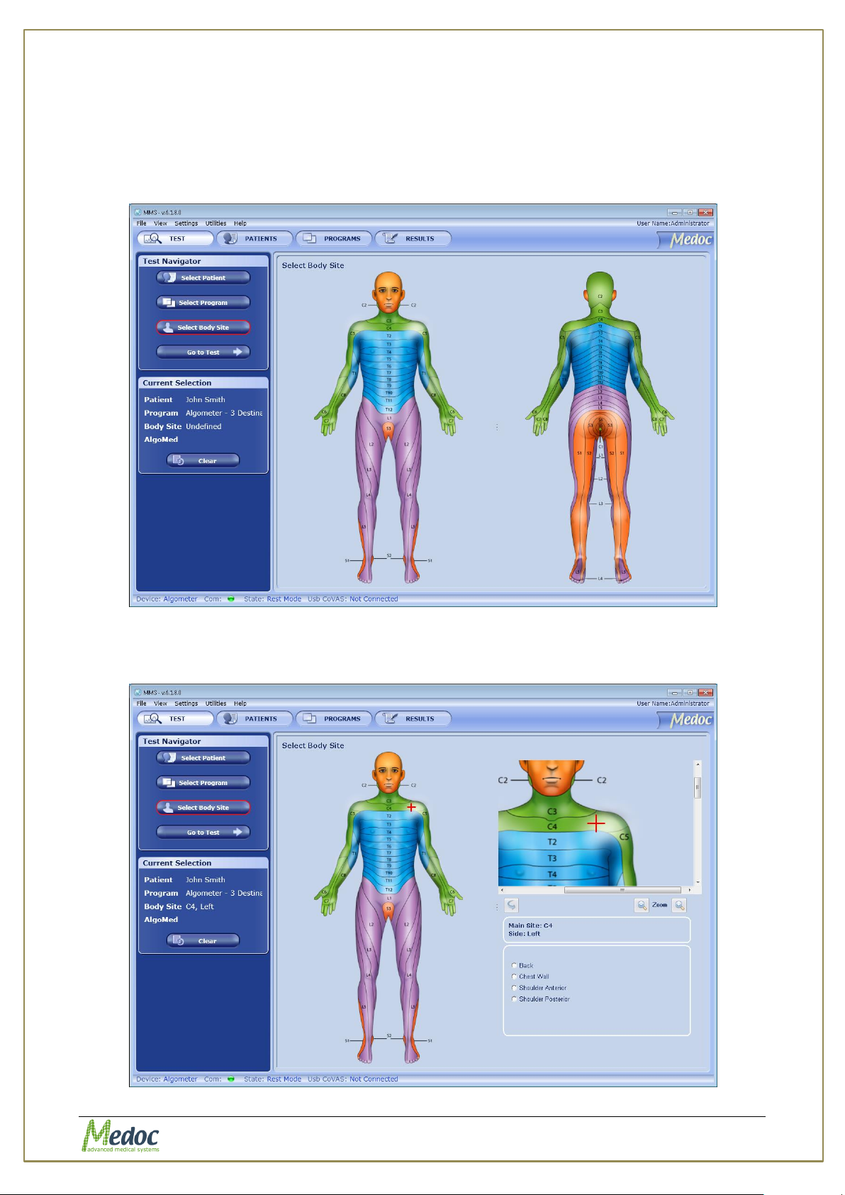
Selecting a tested body site is optional. A test can be initiated without selecting a body site.
1. Click on the Select Body Site button.
The Select Body Site screen is displayed:
Figure 18: Select Body Site screen
2. Click on the Dermatome (Dermatomic area) you wish to use in the current test.
the following screen is displayed:
Figure 19: Select Body Site – Specific site selection
Proprietary 40 of 110
Page 41
AlgoMed Technical Reference Manual
Make sure you have selected both Patient and a Program before you try to
proceed with an actual test.
Do not press on the Algomed device Disp button during a test.
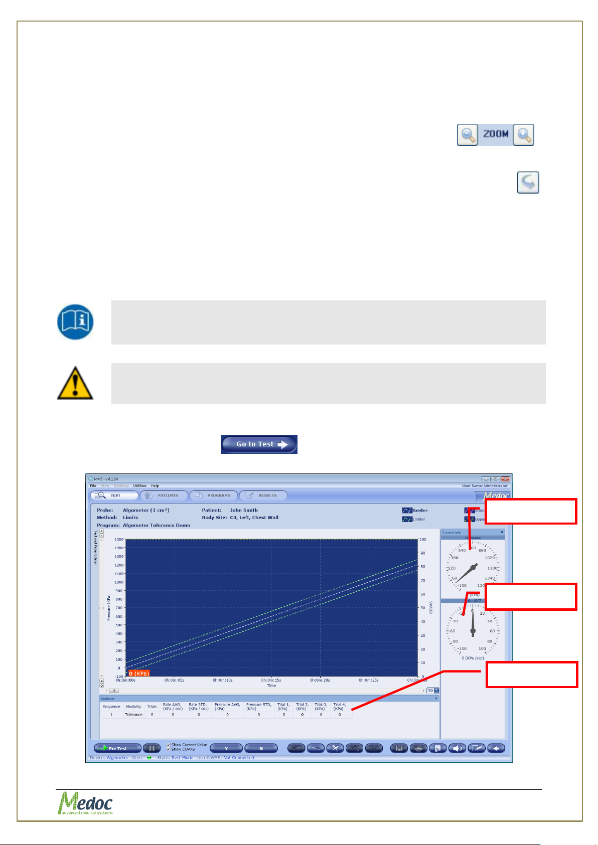
Pressure Gage
Rate Gage
Statistics Pan
3. The following options are available:
3.1. Modify selected Dermatome - by clicking on a different Dermatome.
3.2. Select a specific site for the test from the Specific Site list at the bottom right of the
screen.
3.3. Zoom In / Out the image in order to precisely locate the selected area .
3.4. Mark the Site you test with a red (+) mark.
3.5. Rotate the Dermatome image for Anterior / Posterior view, using the Flip Image
button.
4. Complete the site selection by selecting one of the Specific Sites and continue to Test Run
screen using the Go to Test button.
6.4 Running a Test
The instructions below refer to a Limits test however the procedure for a Ramp and Hold test is
essential the same.
1. Make sure that the Algometer is ON and connected to AlgoMed, see section 10.1.1, page
77.
2. Click the Go to Test button .
The following screen is displayed:
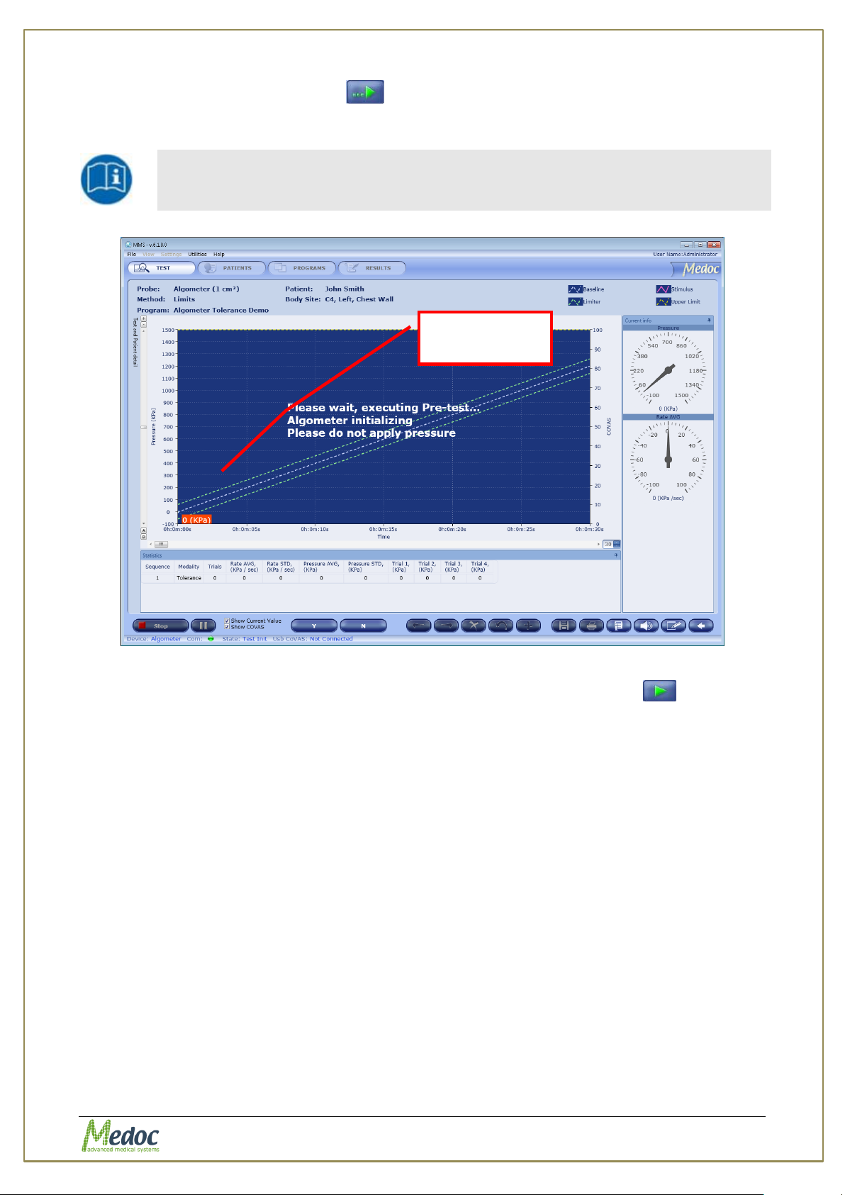
Figure 20: Algometer Pre-Test Screen
Proprietary 41 of 110
Page 42
AlgoMed Technical Reference Manual
Do NOT apply pressure while Algometer initialize as it may affect
measurement!
Trace and
Tolerance lines
3. Click the Start Pre-test button ( ).
The system performs a short pre-test, and initialize Algometer, while displaying a
message.
Figure 21: Algometer Pre-Test Screen
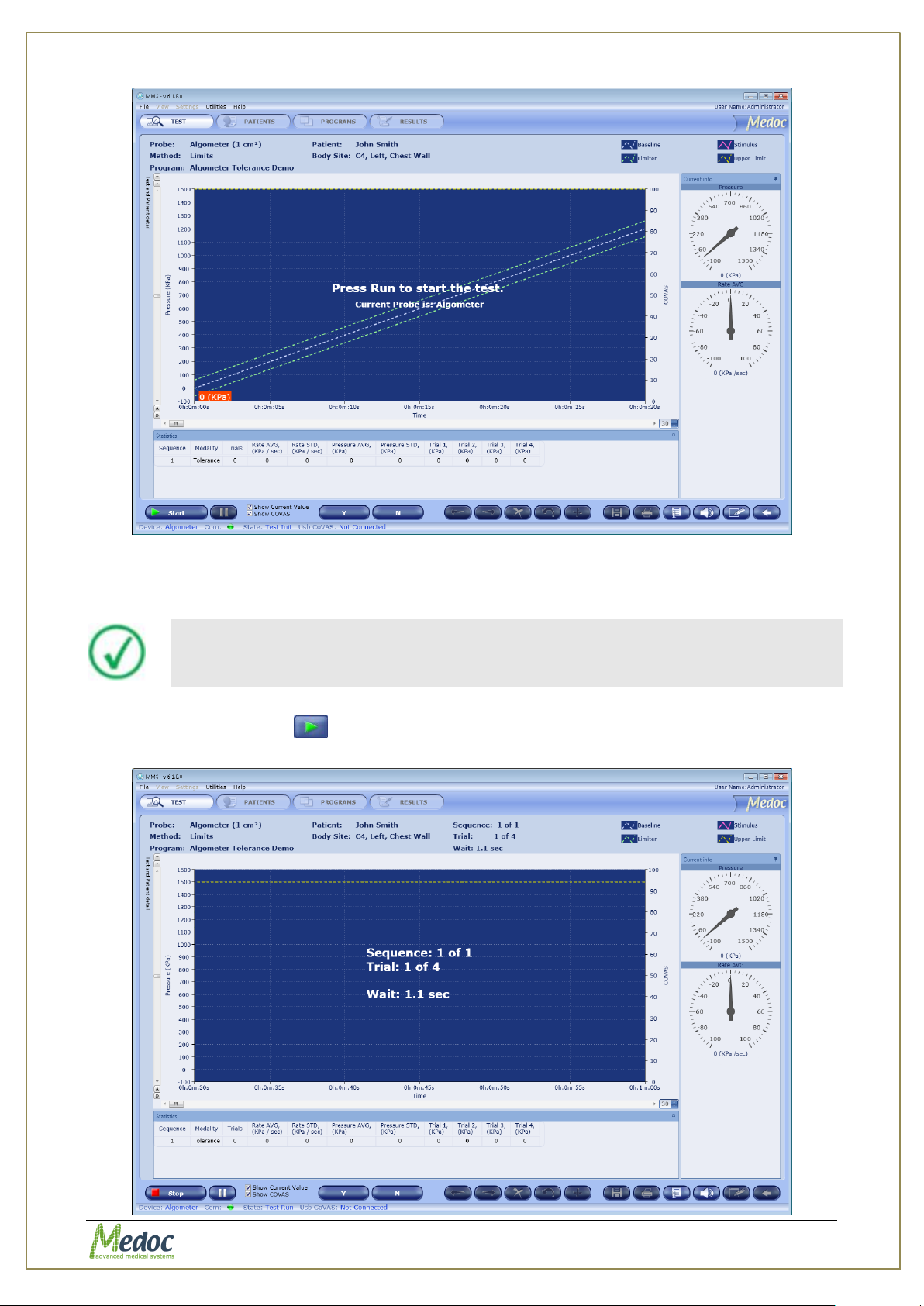
4. After initialization, the Pre-test button is replaced by a Test Run button ( ), and a
Press Run to start the test Message is displayed.
Proprietary 42 of 110
Page 43
AlgoMed Technical Reference Manual
In the Demo mode, a COVAS virtual slider is displayed.
Figure 22: Algometer Test Screen
If the Show COVAS checkbox is selected, you can see the COVAS graph. If it is not
selected, the COVAS graph is not displayed.
5. Click the Run button ( ) to start the test.
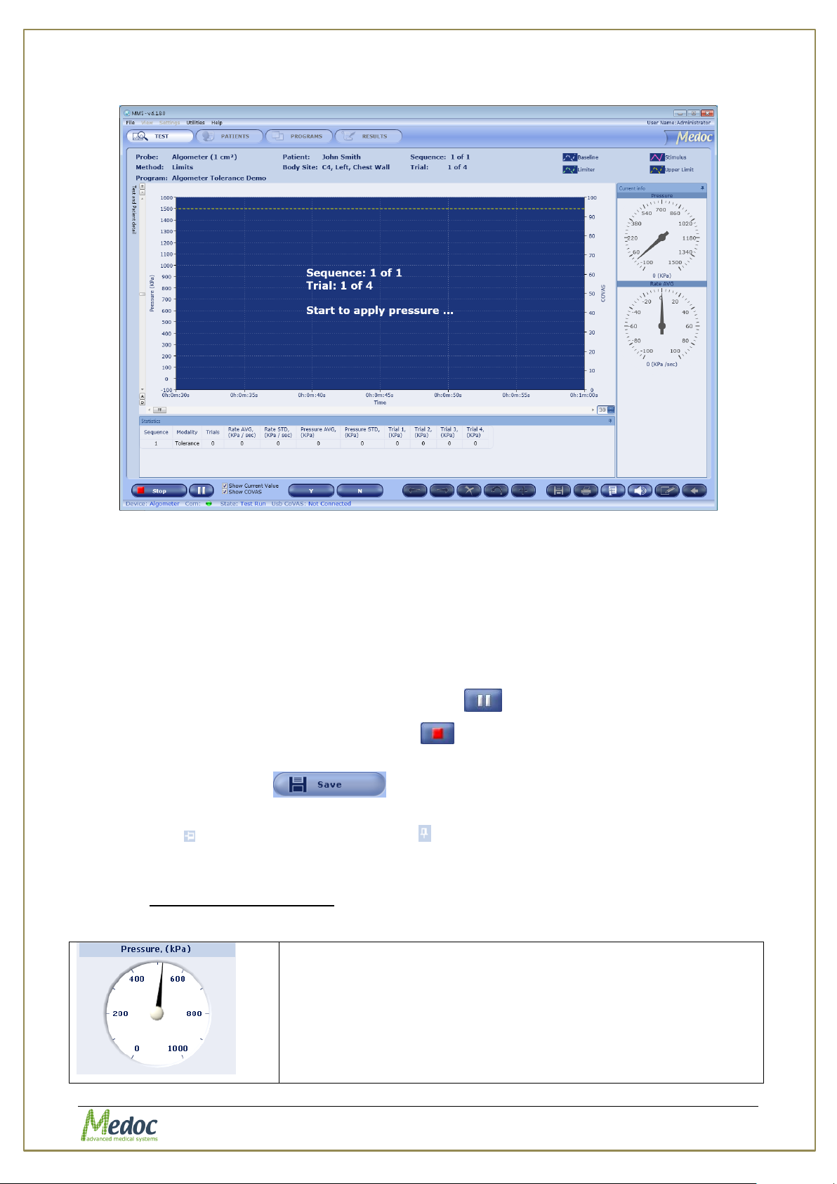
Countdown timer will display time before test and indicate when to start applying pressure.
Proprietary 43 of 110
Page 44
AlgoMed Technical Reference Manual
Pressure gage; displaying applied pressure during the test and
maximum value of each trail as soon as test is ended.
Figure 23: Time before test countdown
Figure 24: Start applying pressure message
6. Patient response may be recorded in the following way:
a. Patient use the USB patient response unit
b. Patient report sensation and operator remove Algometer and pressure drops
In both cases AlgoMed will identify the highest recorded pressure and continue with countdown
of next trail until all trails are complete.
7. To pause the stimulation, click the pause button ( ).
8. To stop the stimulation, click the stop test ( ) button.
The first click stops the test, and initiates the Finalizing test procedure.
9. Click the Save button ( ) to save the program.
For displaying test details permanently, click the pin icon at the top-right corner of the gages /
statistics pan ( ). The pin changes orientation ( ) and the details are displayed also when the
cursor moves away.
Click the pin icon again to release the details display.
6.4.1.1 Additional Features
Table 6: Algometer Test Run features and options
Proprietary 44 of 110
Page 45
AlgoMed Technical Reference Manual
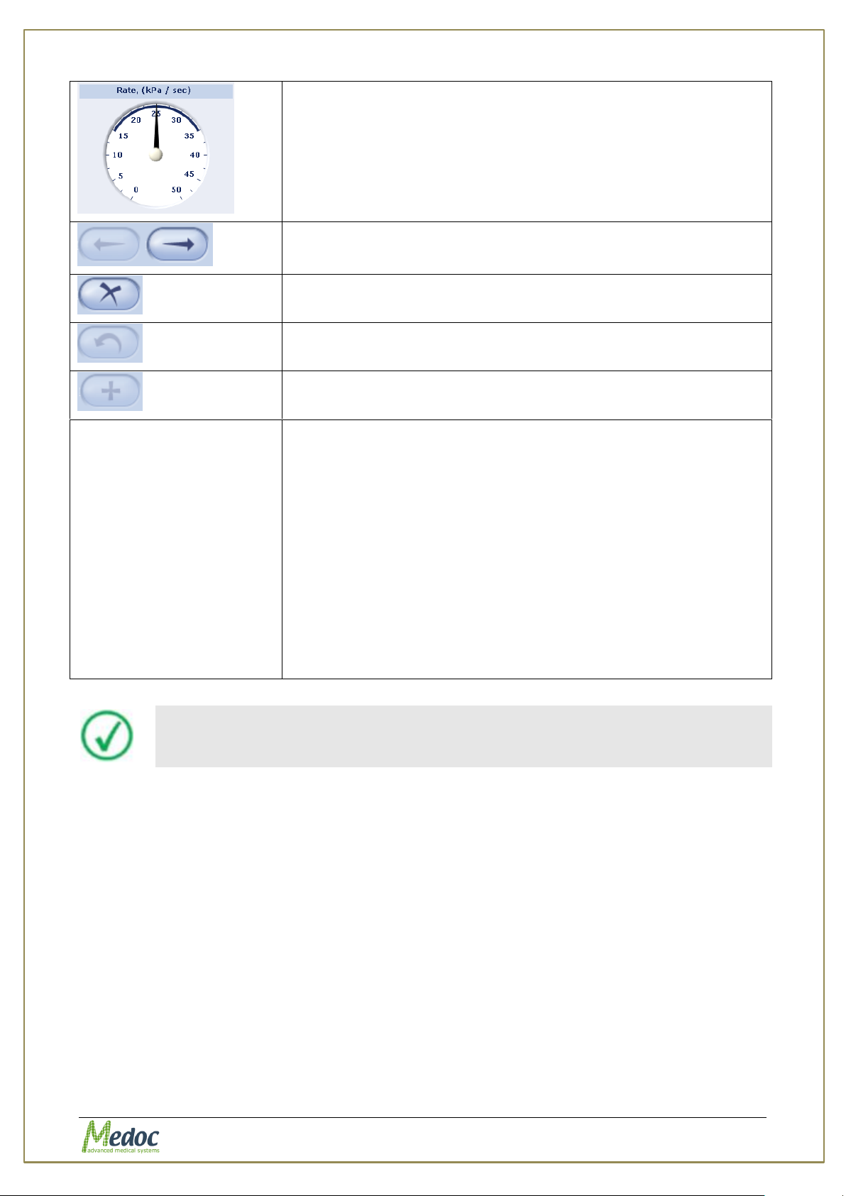
Pressure rate gage; display the applied pressure rate at each
point of time during the test. Tolerance range is displayed as well.
Trail navigation buttons. Can be used to navigate between trails
and sequences post test or while test is paused.
Remove trail button. Can be used to remove failure trail from
statistics.
Restore trail button. Can be used to restore deleted trail back into
statistics.
Mark trail to repeat during a test. Can be used only when test is
paused.
Statistic Pan
Statistic pan display various test parameters such as:
1. Sequence Statistics
1.1. Sequence number
1.2. Number of complete trails
1.3. Average rate applied during sequence
1.4. Standard deviation of rate applied during sequence
1.5. Average pressure recorded during sequence
1.6. Standard deviation of pressure recorded during sequence
2. Trail Information
2.1. Pressure recorded in each of the trails
The system prompts you to save the stimulation data whenever you
attempt to start a new stimulation session or exit the current session.
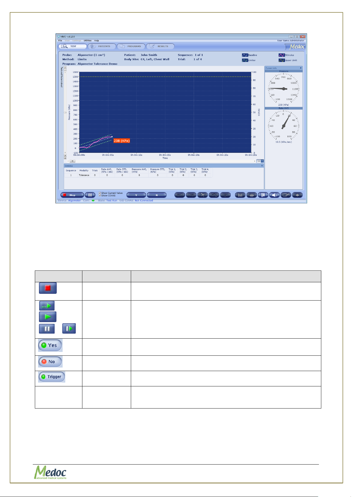
During the test, the test graph is generated and displayed on the screen. Following is an
example:
Proprietary 45 of 110
Page 46
AlgoMed Technical Reference Manual
Button
Key
Action
S
Can be used instead of the Stop button to finalize; then stop
the test.
/
/
/
Spacebar
Can be used instead of the following buttons in sequence:
pre-test / run test / pause / resume test.
Y
Can be used instead of the YES button.
N
Can be used instead of the NO button.
T
Can be use instead of the Trigger button.
Delete
To Delete / Undelete a trail from statistics of a Limits test.
Available only after test is complete and before it is saved.
Delete trail is colored in Yellow.
Figure 25: Real-Time Algometer Limits Test
6.4.2 Test Run Hot Keys
The AlgoMed program enables you to perform test functions, by using specific keyboard keys
(Hot Keys).
The following Hot Keys are available:
Table 7: Hot Keys
The hot keys are not case sensitive and perform same functions with upper case letters (when
the Caps Lock key is pressed.
Proprietary 46 of 110
Page 47
AlgoMed Technical Reference Manual
The more criteria you define using the filter, the shorter the list that will
be displayed.
It is possible to change column order by drag and drop it to required place.
Create a new program
Duplicate selected program
7. Program Management
This chapter describes how to manage your stimulation programs. Programs can be created,
duplicated or removed from the database. Following are the detailed individual parameters for
program.
7.1 Program List
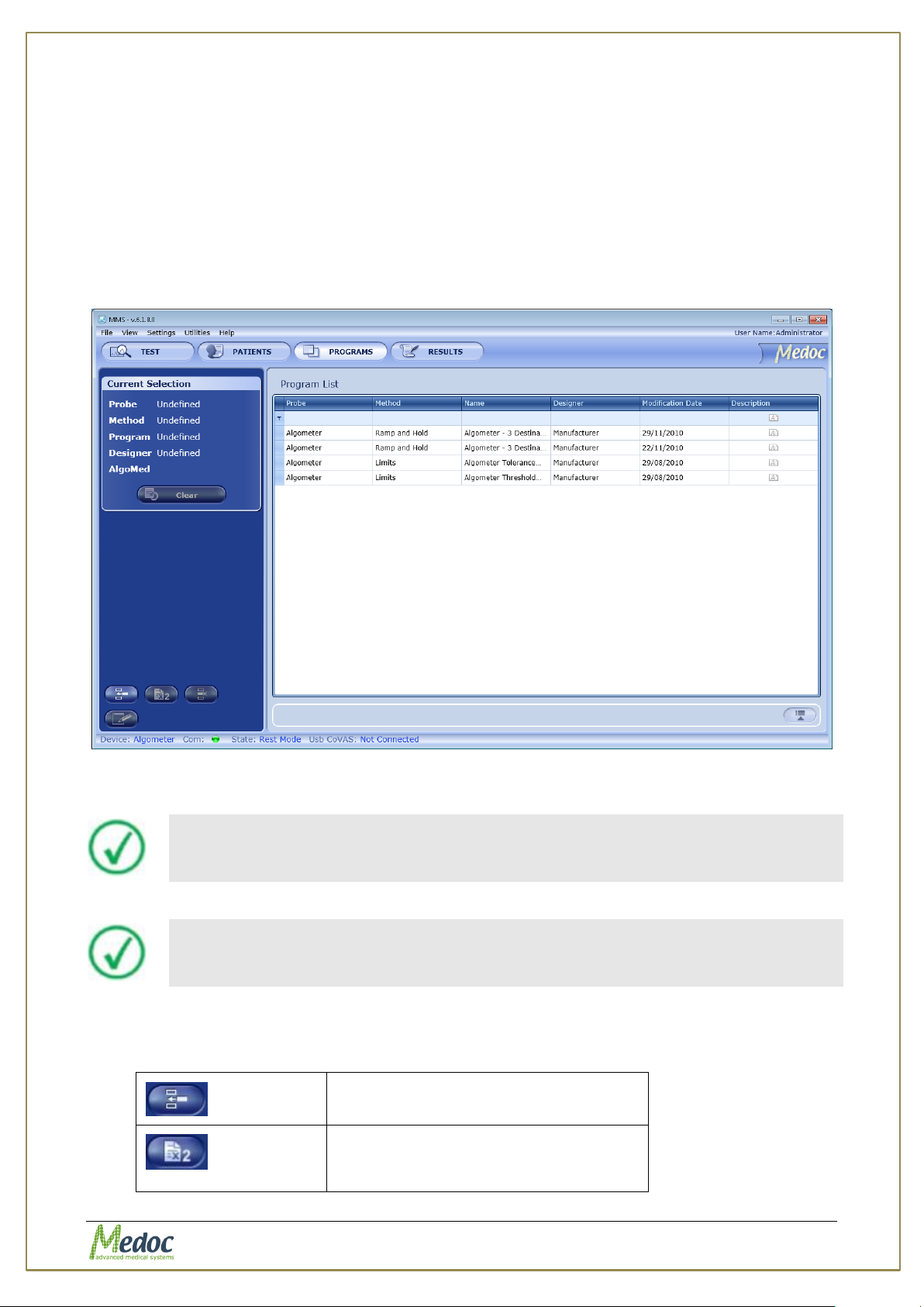
The Program screen enables you to manage programs (add, remove, edit etc.).
1. To access the program database, click the Programs button at the toolbar. The following
screen is displayed:
Figure 26: Program Management screen
2. To narrow down the displayed list use the filter row.
3. To clear the filtered list, select the (All) option from the filter drop down list.
The following options are available in the Program Management screen:
Proprietary 47 of 110
Page 48
AlgoMed Technical Reference Manual
Delete selected program
Edit selected program
or
Show or Hide program preview
Display program details.
Display program graph preview.
Available on selected methods.
View selected test instructions.
View recent program modification dates.
Current Selection control - displays the selected program information.
Current Thermode control - displays the Thermode that is used for the selected program.
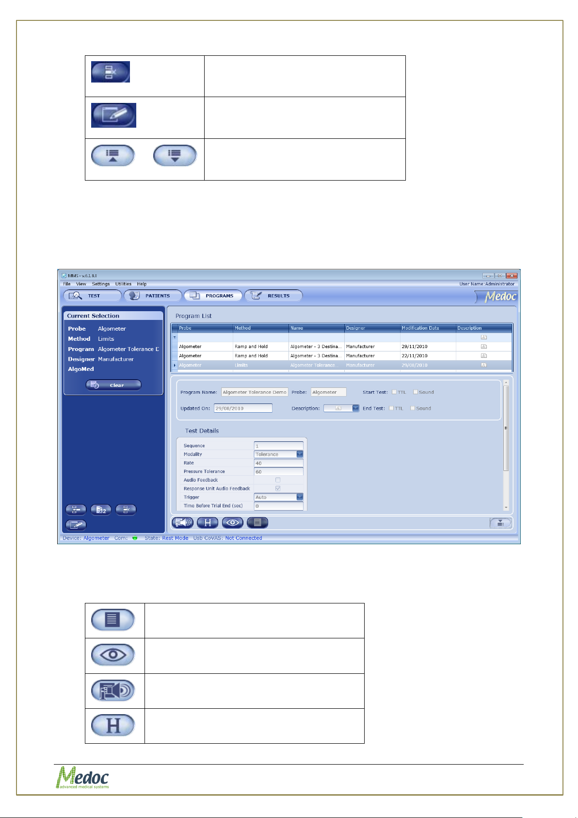
When you open the Program Preview bar, the following screen is displayed:
Figure 27: Program Management – Program Preview
The following options are available in the Program Preview:
Proprietary 48 of 110
Page 49
AlgoMed Technical Reference Manual
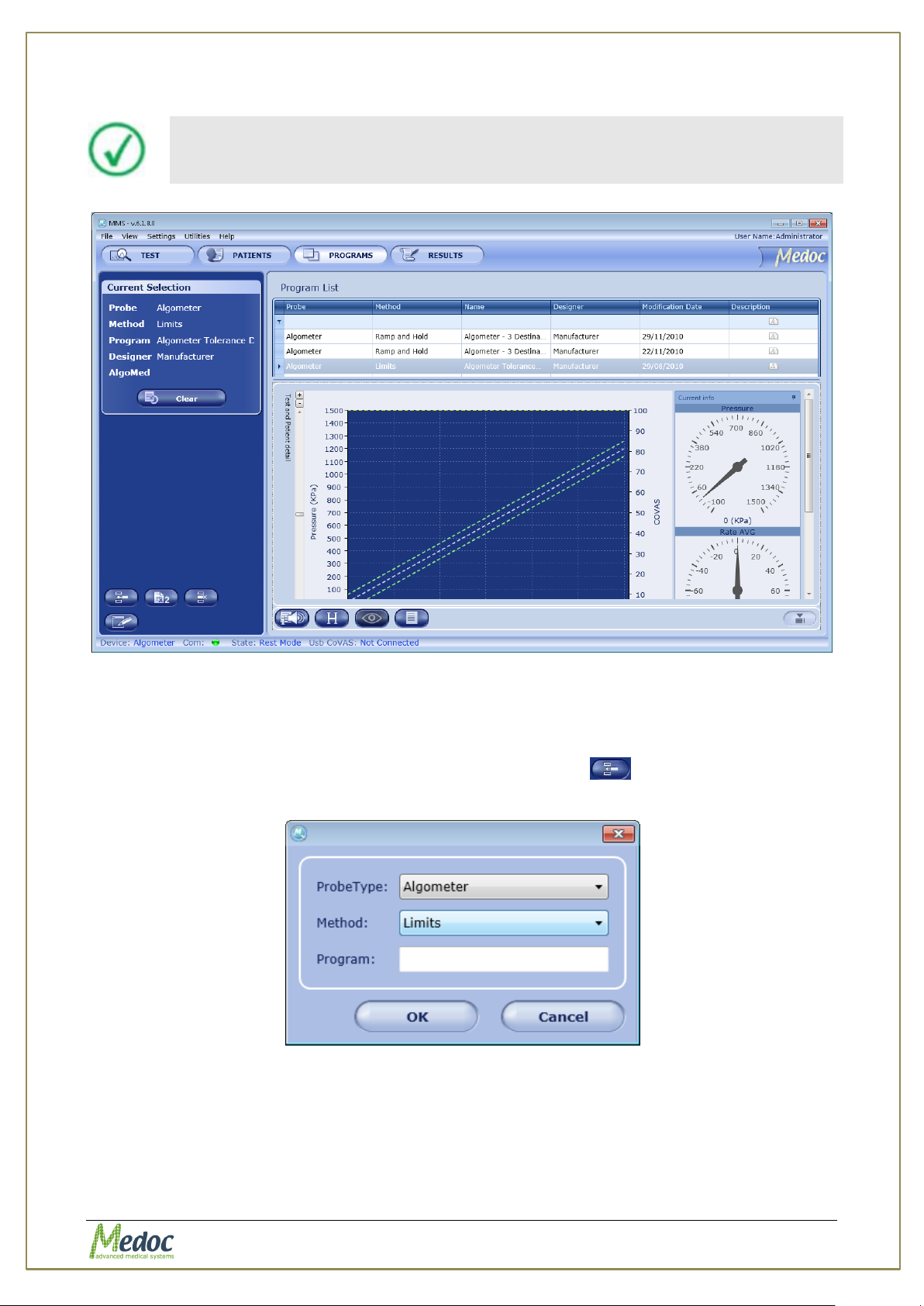
Program details cannot be edited from the preview screen.
Figure 28: Program graph preview
7.2 Creating a New Program
To create a new program, perform the following procedure:
1. From the Programs screen, click the Create New Program ( ) icon.
The following dialog is displayed:
Figure 29: New Program Screen
2. From the Probe Type drop-down list, select Algometer. Other options may be available
depending on your licensing agreement and supported devices.
3. From the Method drop-down list, select the required stimulation method: Limits or Ramp
and Hold.
Proprietary 49 of 110
Page 50
AlgoMed Technical Reference Manual
Displays a list of the program revision history by version date and username.
Displays the Test Instructions Editor for editing unique test instructions. Refer
to section X2X, page X55.
Returns to the previous menu.
Copies the selected record (sequence).
Pastes the copied record to the right of the selected record.
Adds a new record to the end of the current program.
Adds a new record to the left of the selected record.
Previews the program graph.
Checks program validity, and marks missing or incorrect parameters.
Saves the information displayed.
4. Type the program name.
For faster identification, it is advisable to type a meaningful name.
5. Click OK.
The Program Details screen is displayed (see below) where you can edit the program
parameters (see following section).
7.3 Editing Program Parameters
The program details screen enables the operator to edit the program details and parameters.
Below is a description of the available editing operations which are shown in the left side bar:
7.3.1 Program Details
The following screen enables the formation of program protocols.
Following are sampled menus:
7.3.1.1 Limits
In this method, the operator generates a number of stimuli of continuously changing intensity.
With each stimulus, when the subject perceives a predefined sensation, he/she notify the
operator who stops the stimulus. Optional Patient Response Unit is available to allow marking
of exact pressure.
Proprietary 50 of 110
Page 51
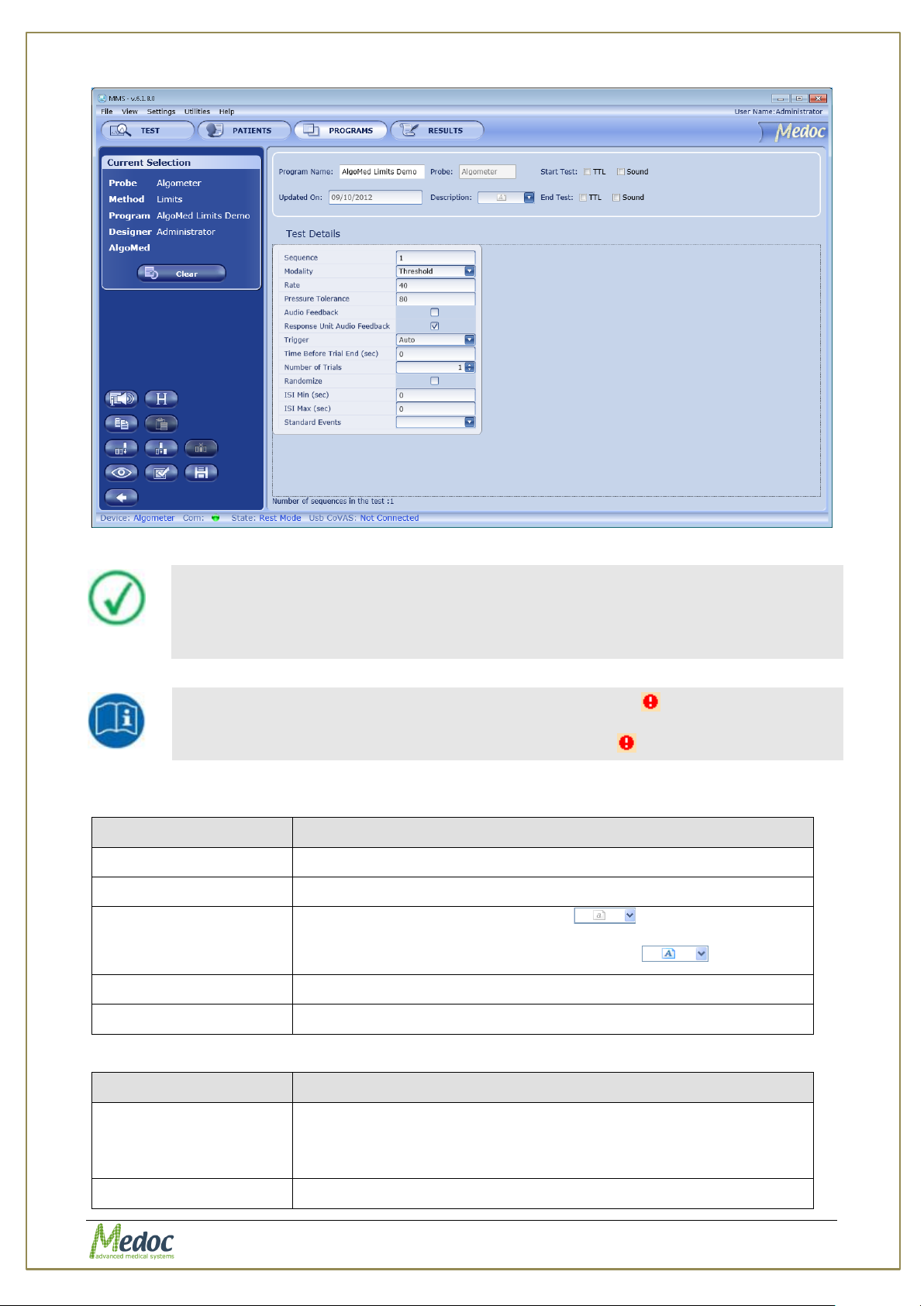
AlgoMed Technical Reference Manual
When adding or editing programs, follow these rules:
Enter meaningful information in the Program Description section of the
screen.
Define all the parameters of a sequence for that sequence to be valid.
Missing or incorrect parameters are identified by an icon that flashes
next to the relevant field. A short description of the malfunction can be
displayed by holding the cursor over the relevant icon.
Parameter
Description
Program name
The program name (editable).
Probe
The probes used with this program.
Description
Under Description, click the arrow ; then type free text
to describe the program.
The Description icon is indicated as active ( ).
Update on
The date on which the latest changes were made and saved.
Start test/End test
Defines how these events are indicated: TTL, sound, or both.
Parameter
Description
Modality
Two different types of sensation can be delivered to the
subject:
Threshold; Tolerance
Rate (KPa/sec)
The required rate which pressure will be applied to tested
Figure 30: Algometer Program Menu – Limits
The parameters available for program creation at this stage are as follows:
Table 8: Program Details
Table 9: Program Parameters
Proprietary 51 of 110
Page 52
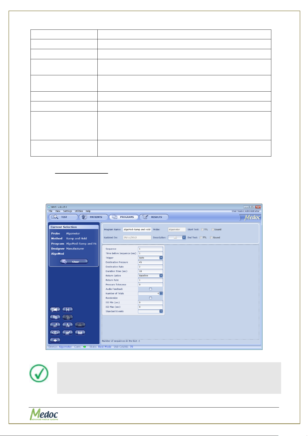
AlgoMed Technical Reference Manual
subject by the operator. 0.1 – 100 KPa/sec
Tolerance (KPa)
The required pressure tolerance during test, 0.1 – 1000 KPa.
Audio Feedback
Enable / disable the rate audio rate monitoring
Response Unit Audio
Feedback
Enable / disable the sound feedback when patient press
response unit
Time Before Trail
End (sec)
Time before trail end, after pressure drops, and before
continues to next trail countdown.
Number of Trials
The numbers of trials in the sequence, 1 – 100 trails.
Randomize with next
Randomizes the next trial or sequence.
ISI Min (sec) /
ISI Max (sec)
Inter Stimuli Interval. Defines the min. and max. Time between
successive trials (stimuli), and randomizes the actual time
between them. If these values are the same, then the interval
is fixed. – between 0 to 600
Standard Events
Event marked at the onset of the stimulus. Select event from
the available list: Onset1-Onset5. See section 7.3.2
When adding or editing programs, follow these rules:
Enter meaningful information in the Program Description section of the
screen.
Define all the parameters of a sequence for that sequence to be valid.
7.3.1.2 Ramp and Hold
In this method, the operator generates stimuli of changing intensity according to predefined
course. Pressure can be increased at predefined rate to a specific intensity level and
maintained manually during predefined time. Pressure course is displayed on the screen at real
time and adjusted accordingly to the required pressure intensity at each moment.
Figure 31: Algometer Program Menu – Ramp & Hold
Proprietary 52 of 110
Page 53
AlgoMed Technical Reference Manual
Missing or incorrect parameters are identified by an icon that flashes
next to the relevant field. A short description of the malfunction can be
displayed by holding the cursor over the relevant icon.
Parameter
Description
Program name
The program name (editable).
Probe
The probes used with this program.
Description
Under Description, click the arrow ; then type free text
to describe the program.
The Description icon is indicated as active ( ).
Update on
The date on which the latest changes were made and saved.
Start test/End test
Defines how these events are indicated: TTL, sound, or both.
Parameter
Description
Time Before
Sequence (sec)
The time interval before the first trial of the current sequence
between 0 to 600 seconds.
External Trigger /
Manual Trigger
Triggers the beginning of a stimulation sequence. Key board hot
key T can be used as a manual trigger.
External trigger is not active.
Destination Pressure
(Kpa)
The maximal pressure to be applied during the trial.
Destination Rate
(KPa/sec)
The required rate which pressure will be applied to tested
subject by the operator. 0.1 – 100 KPa/sec
Duration Time (sec)
Defines the duration in seconds, between the Destinations to
the End of duration of maximal trial pressure.
Return Option
Defines whether the pressure returns to the baseline or
proceeds to the destination pressure of the next sequence.
Select the relevant option from the drop-down menu.
Note that when the “next destination” option is selected certain
fields become inactive, because they are no longer relevant (for
example, the Number of Trials turns to ‘1’).
Return Rate
(KPa/sec)
The required rate which pressure will be reduced by the
operator. 0.1 – 100 KPa/sec
Pressure Tolerance
(KPa)
The required pressure tolerance during test, 0.1 – 1000KPa.
Audio Feedback
Enable / disable the rate audio rate monitoring
Number of Trials
The numbers of trials in the sequence, 1 – 100 trails.
Randomize with next
Randomizes the next trial or sequence.
ISI Min (sec) /
ISI Max (sec)
Inter Stimuli Interval. Defines the min. and max. Time between
successive trials (stimuli), and randomizes the actual time
between them. If these values are the same, then the interval
is fixed. – between 0 to 600
Standard Events
Event marked at the onset of the stimulus. Select event from
The parameters available for program creation at this stage are as follows:
Table 10: Program Details
Table 11: Program Parameters
Proprietary 53 of 110
Page 54
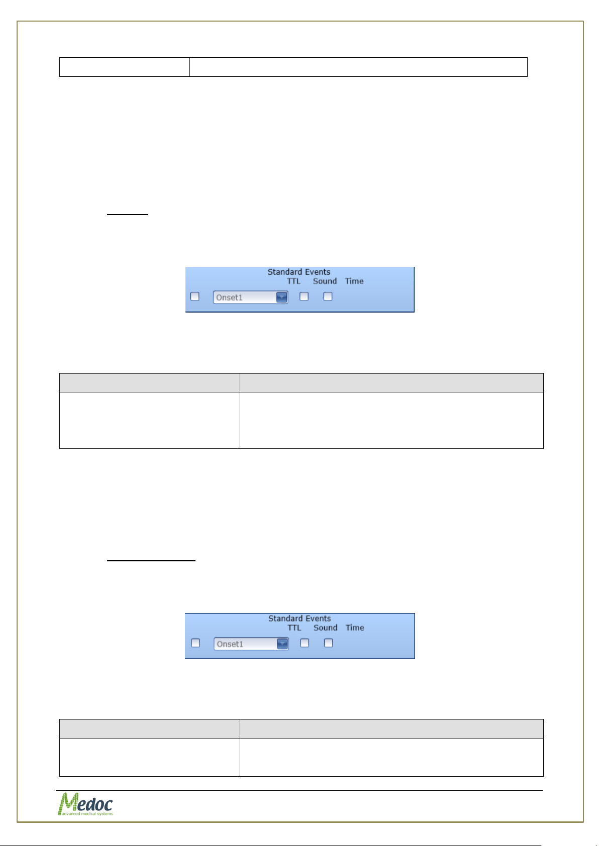
AlgoMed Technical Reference Manual
the available list: Onset1-Onset5. See section 7.3.2
Parameter
Description
Onset 1 – Onset 5
Marks the onset of stimulus. The event will be given at
the time the operator starts to apply pressure. The
different onset events (1-5) can be used to distinguish
between sequences if needed.
Parameter
Description
Onset 1 – Onset 5
Marks the onset of stimulus. The event will be given at
the time the operator starts to apply pressure. The
different onset events (1-5) can be used to distinguish
7.3.2 Standard Events
Standard events are used to mark defined and regular events during the test such as the onset
of stimulus. The available standard events vary depending on the test method. Currently the
AlgoMed only supports the onset event in both the limits and ramp and hold test methods. The
standard events can be noted by playing a sound, placing a mark on the display both. If a
display mark is used, the event is also saved with test results and can be viewed later in excel
export.
7.3.2.1 Limits
1. From the Program Details screen, click the Standard events arrow at the bottom of the
relevant sequence setting (column). The following dialog is displayed, listing the standard
events, applicable to the Limits method:
Figure 32: Limits – Standard Events Dialog
The following event can be marked:
Table 12: Events - Limits
2. Select the request mark type:
a. TTL – a mark will be displayed on screen and indication will be added to test results
and visible in excel export.
b. Snd – a sound will be played. To configure the sound refer to section 10.3.5.
3. Click anywhere on the screen, or on the X mark at the corner of the window, to close the
Standard Events dialog.
7.3.2.2 Ramp & Hold
1. From the Program Details screen, click the Standard events arrow at the bottom of the
relevant sequence setting (column). The following dialog is displayed, listing the standard
events, applicable to the Ramp & Hold method:
Figure 33: Ramp & Hold – Standard Events Dialog
The following event can be marked:
Table 13: Events – Ramp & Hold
Proprietary 54 of 110
Page 55
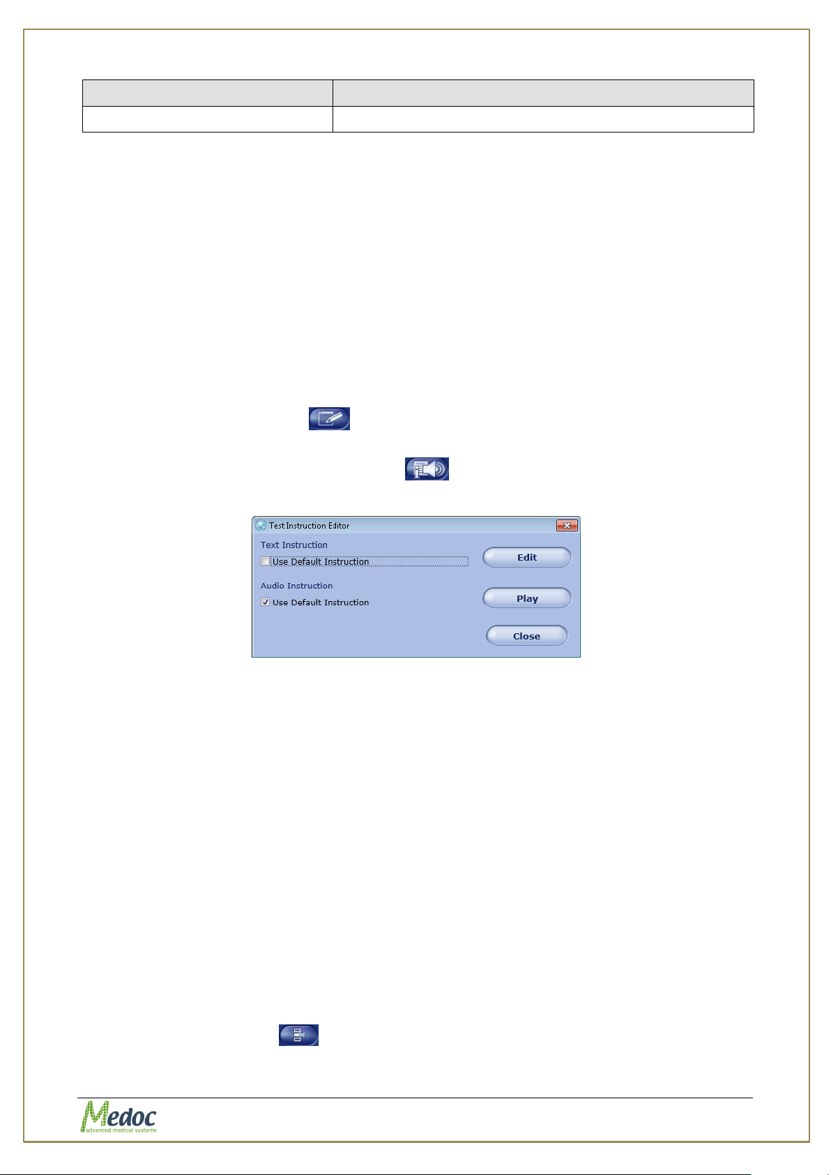
AlgoMed Technical Reference Manual
Parameter
Description
between sequences if needed.
2. Select the request mark type:
c. TTL – a mark will be displayed on screen and indication will be added to test results
and visible in excel export.
d. Snd – a sound will be played. To configure the sound refer to section 10.3.5.
3. Click anywhere on the screen, or on the X mark at the corner of the window, to close the
Standard Events dialog.
7.4 Unique Test Instructions
In some cases, the general program instructions do not fully apply to specific programs, and
unique instructions are required.
To enter unique instructions, perform to the following procedure. All other (standard) tests will
be assigned the standard instructions, as entered in section 10.3.2, page 90.
1. From the program list at the left, select the required program, and double-click, or click the
Edit program details button .
The Programs menu is displayed.
2. Click the Accesses test instructions button .
The following screen is displayed:
Figure 34: Test Instructions Editor
3. To edit the textual instructions,
3.1. Deselect the relevant Use default instruction checkbox.
The Edit button becomes enabled.
3.2. Click the Edit button.
The text editor is displayed, displaying the standard instructions.
3.3. Edit the instructions as required, as described in section 10.3.2.1, page 90.
4. To replace the audio instructions,
4.1. Deselect the relevant Use default instruction checkbox.
The Play button becomes an enabled Browse button.
4.2. Click the Browse button.
The Audio instruction screen is displayed.
4.3. Replace the instructions file, as described in section 10.3.2.2, page 91X
7.5 Removing A Program
To remove a program from the program list:
1. Click the Remove icon ( ).
2. Click Yes to the prompt.
The selected program is deleted.
Proprietary 55 of 110
Page 56
AlgoMed Technical Reference Manual
Program files can be imported to the AlgoMed program only if they were
saved by the same program version by which they are imported.
The AlgoMed software identifies and allows you to manually solve any
conflicts that may arise when importing programs. For example, programs
with the same name.
7.6 Duplicate A Program
To duplicate a program from the program list:
1. Click the Duplicate icon ( ).
2. The selected program was duplicated and given a unique name automatically (the name is
editable).
7.7 Edit A Program
To edit a program from the program list:
1. Click the Edit icon ( ).
2. The selected program details screen is open and can be edited.
7.8 Import / Export Program
It is possible to export and import program details, by using the AlgoMed software. The format
used is secure, and can be read only by the AlgoMed software. Its extension is .ats.
When exporting program details, multiple selections are available, by using the Ctrl and Shift
buttons.
In order to export AlgoMed programs follow the procedure below:
1. Open the program list in the Programs screen.
2. Select the programs to export.
3. Click File Export.
4. Select the location and name of the exported programs.
5. Click the Save button.
The selected programs are saved to the selected location under the selected name.
In order to import AlgoMed programs follow the procedure below:
1. Click File Import.
2. Browse to the location of the exported programs and select the program you want to
import.
3. Click on the Open button.
The imported programs are added to your program list.
Proprietary 56 of 110
Page 57
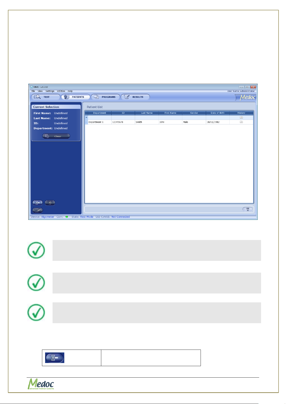
AlgoMed Technical Reference Manual
The more criteria you define using the filter, the shorter the list that will
be displayed.
In order to add / remove fields from Patient table, see section0, page 77.
It is possible to change column order by drag and drop it to required place.
Create a new program
8. Patient Management
8.1 Patients List
The Patients screen enables you to manage patients (add, remove, edits etc.) and department
information.
1. To access the patient database, click the Patients button at the toolbar. The following
screen is displayed:
Figure 35: Patients List
2. To narrow down the displayed list use the filter row.
3. To clear the filtered list, select the (All) option from the filter drop down list.
The following options are available in the Patient Management screen:
Proprietary 57 of 110
Page 58
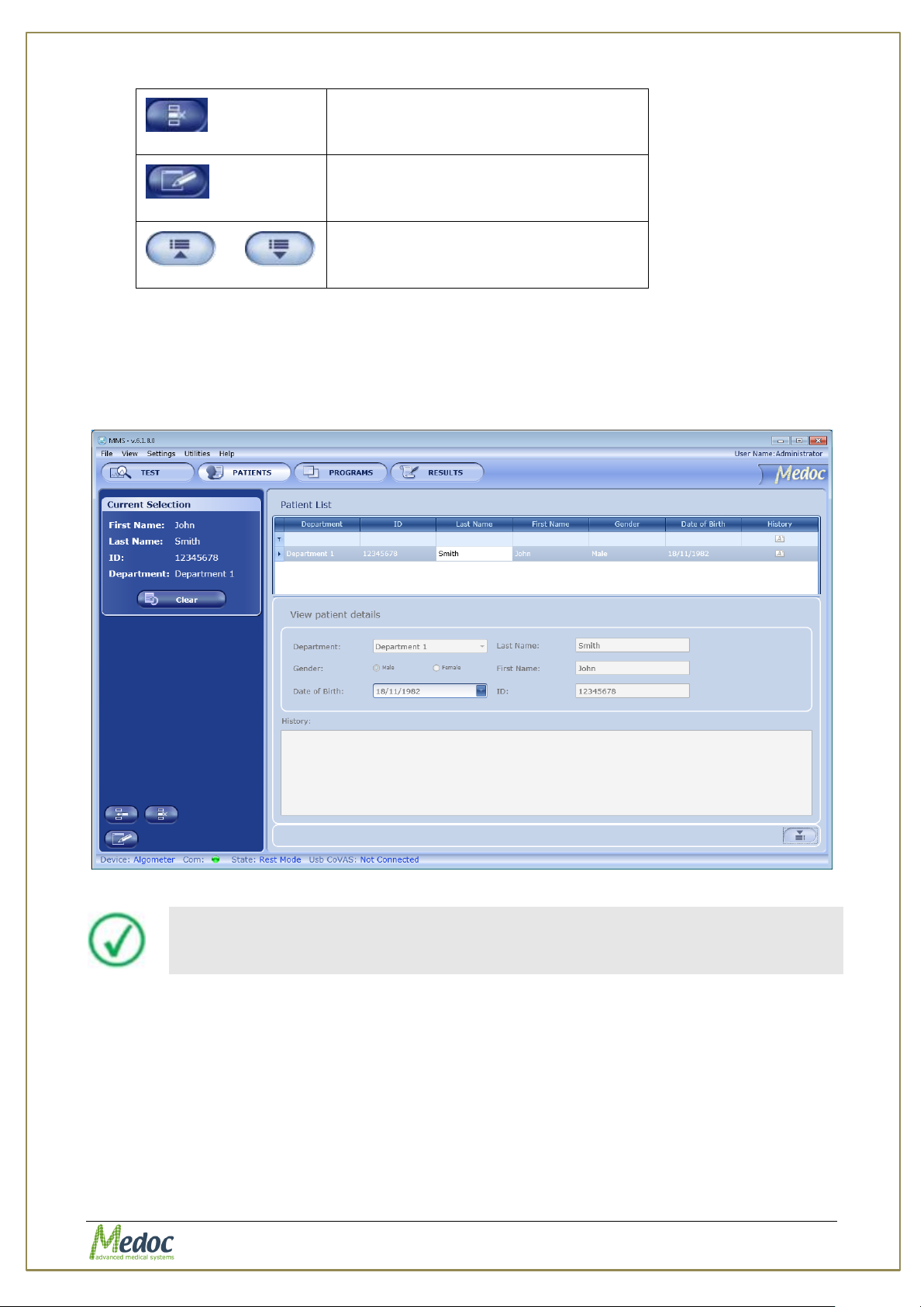
AlgoMed Technical Reference Manual
Delete selected program
Edit selected program
or
Show or Hide program preview
Patient details cannot be edited from the preview control screen
Current Selection control - displays the selected program information.
When you open the Patient Preview bar, the following screen is displayed:
Figure 36: Patient Management – Patient details preview
Proprietary 58 of 110
Page 59
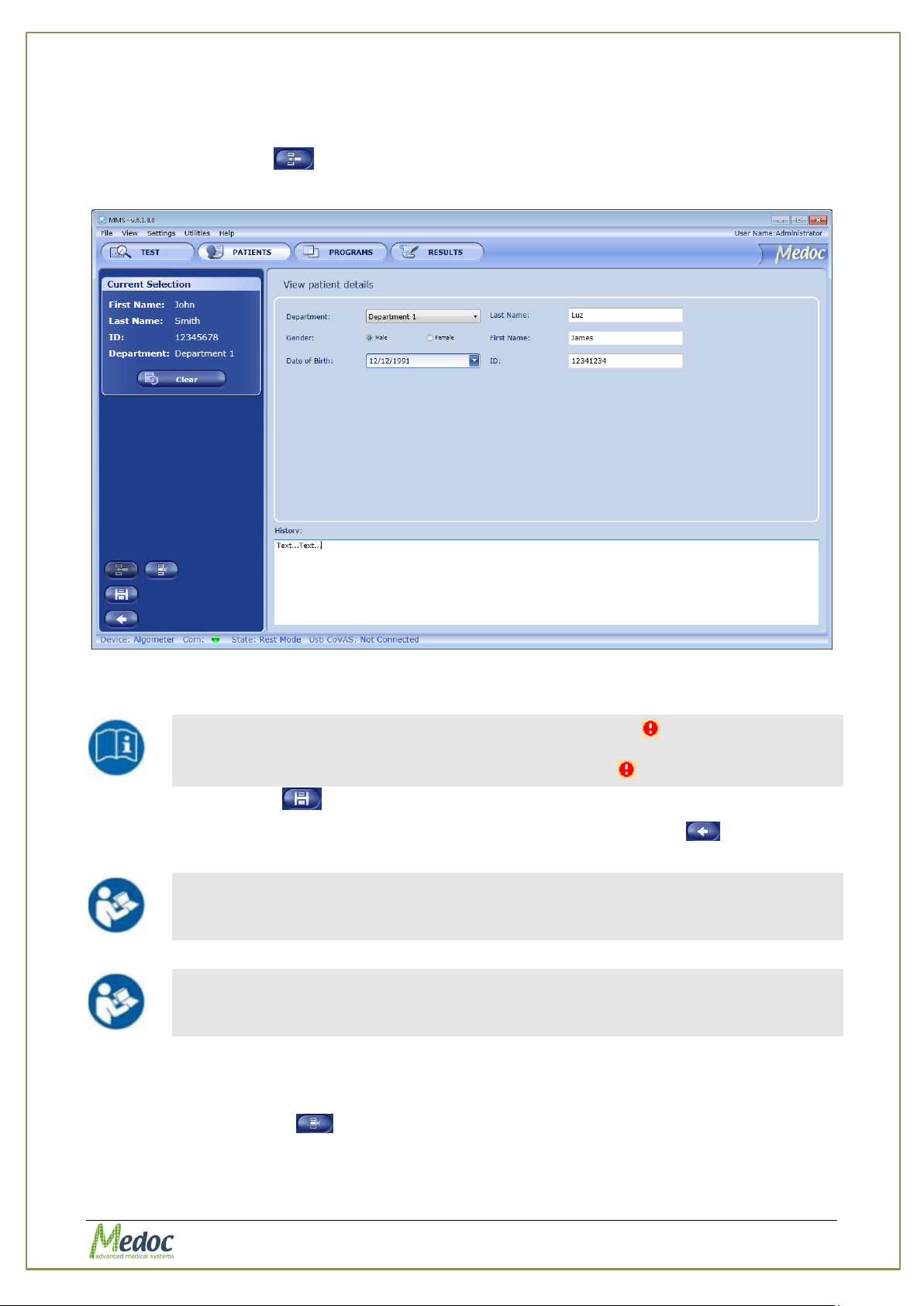
AlgoMed Technical Reference Manual
Missing or incorrect parameters are identified by an icon that flashes
next to the relevant field. A short description of the malfunction can be
displayed by holding the cursor over the relevant icon.
Adding a department can only be done by an administrator. See section
8.5 page 60.
The information displayed on the screen (field names) can be customized
according to the setup defined by each user. Refer to section 0, page 77.
8.2 Add New Patient
To add a patient to the patients list:
1. Click the Add icon ( ).
The Patient details screen is displayed:
Figure 37: Patients Editor Screen
2. Insert all the relevant patient data.
3. Click the Save icon ( ).
4. After adding and saving all the required patients, click the Return icon ( ) to return to
the Patients list screen.
8.3 Remove Patient
To remove a patient from the patients list:
3. Click the Delete icon ( ).
4. Click Yes to the prompt.
The selected patient is deleted.
Proprietary 59 of 110
Page 60
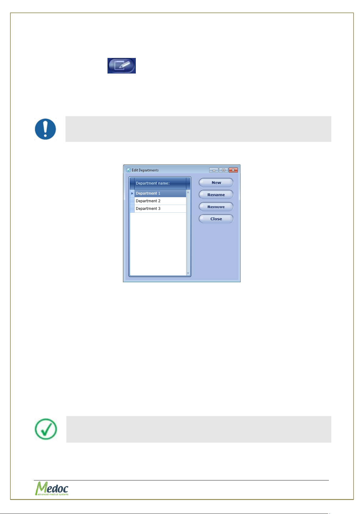
AlgoMed Technical Reference Manual
Department management is enabled according to the authorization level of
the current user. For further information, refer to Table 21, page 82.
Patient files can be imported to the AlgoMed program only if they were
saved by the same program version by which they are imported.
8.4 Edit Patient Details
To edit a patient from the patients list:
5. Click the Edit icon ( ).
6. The selected patient parameters screen is open and can be edited.
8.5 Department Management
The AlgoMed software enables you to mange (Add, Edit, Remove) your patient department.
1. From the Utilities menu at the top of the screen, select the Department option.
The Edit departments menu is displayed:
Figure 38: Edit Department Menu
2. To define a new department, click the New button; then, type the department name.
3. To rename a department, select the required department; then click the Rename button.
(Available only for System Administrators and Medical Supervisors)
4. To remove a department, select the required department; then click the Remove button.
At the prompt click the OK button.
(Available only for System Administrators and Medical Supervisors)
5. To close the dialog, click the Close button.
8.6 Import / Export Patient Lists
It is possible to export and import patient details, by using the AlgoMed software. The format
used is secure, and can be read only by the AlgoMed software. Its extension is .ats.
When exporting patient details, multiple selections are available, by using the Ctrl and Shift
buttons.
In order to export AlgoMed patients follow procedure below:
1. Open the patient list in the Patient screen.
Proprietary 60 of 110
Page 61
AlgoMed Technical Reference Manual
The AlgoMed software identifies and allows you to manually solve any
conflicts that may arise when importing patients. For example, patients
with the same unique field.
2. Select the patients to export.
3. Click File Export.
4. Select the location and name of the exported patients.
5. Click the Save button.
The selected patients are saved to the selected location under the selected name.
In order to import AlgoMed patients follow the procedure below:
1. Click File Import.
2. Browse to the location of the exported patients and select the patients you want to import.
3. Click on the Open button.
The imported patients are added to your patients list.
Proprietary 61 of 110
Page 62
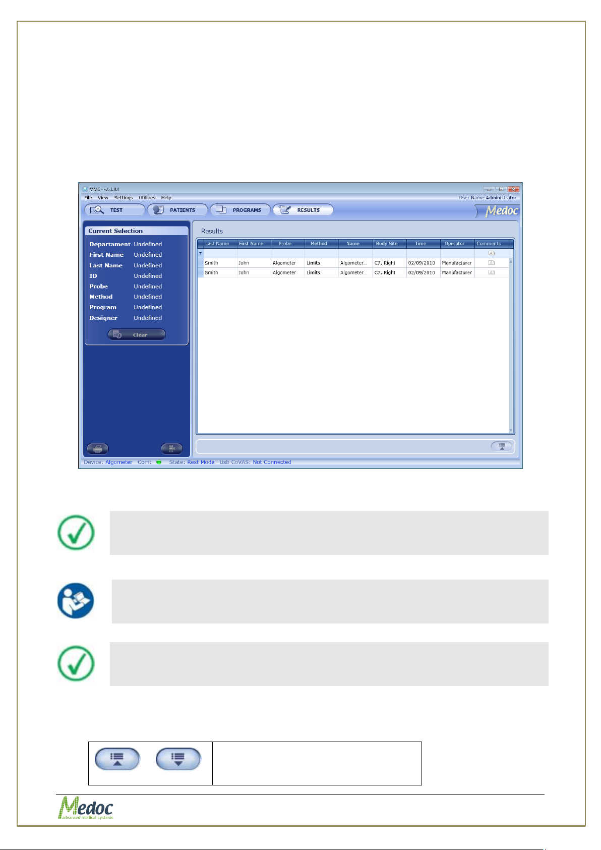
AlgoMed Technical Reference Manual
The more criteria you define using the filter, the shorter the list that will
be displayed.
In order to add / remove fields from Results table, see section 10.1.3,
page 80.
It is possible to change column order by drag and drop it to required place.
or
Show or Hide Results preview
9. Results Management
The Results List screen lists the results of the recent test.
9.1 Results List
The Results screen enables you to manage Results (view, print, delete, etc.).
1. To access the results database, click the Results button at the toolbar. The following
screen is displayed:
Figure 39: Results List
2. To narrow down the displayed list use the filter row.
3. To clear the filtered list, select the (All) option from the filter drop down list.
The following options are available in the results management screen:
Proprietary 62 of 110
Page 63
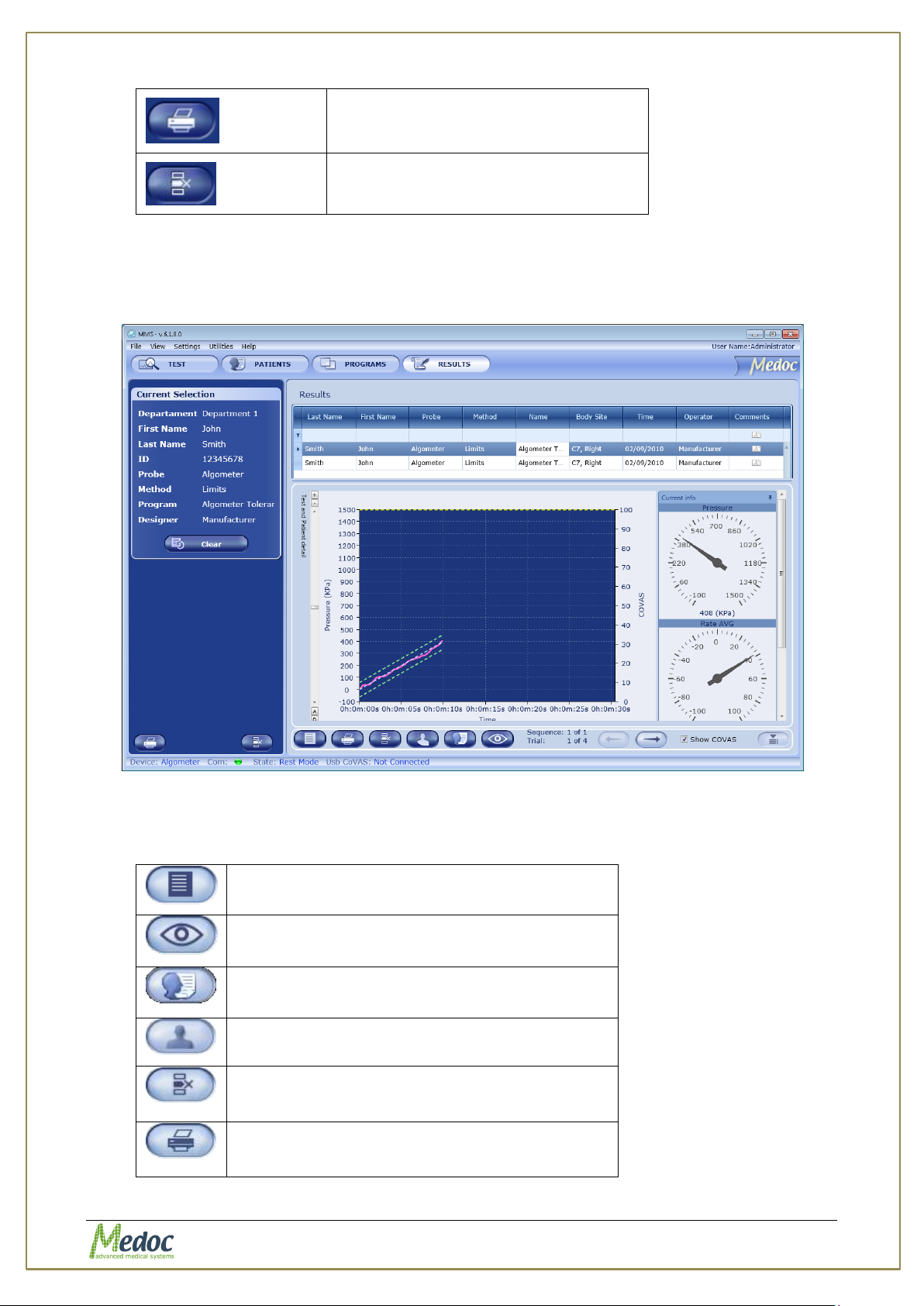
AlgoMed Technical Reference Manual
Print Selected Results file / files
Delete selected Results file from
AlgoMed Data Base
Display Results details.
Display Results graph preview.
Available on selected methods.
Display test subject details preview.
Display the Result Body Site.
Available only if a Body Site was selected.
Delete selected results file.
Print selected results file.
Current Selection control - displays the selected program information.
When you open the Results preview bar, the following screen is displayed:
Figure 40: Result preview display
The following options are available:
Proprietary 63 of 110
Page 64
AlgoMed Technical Reference Manual
Results files can be imported to the AlgoMed program only if they were
saved by the same program version by which they are imported.
The AlgoMed software identifies and allows you to manually solve any
conflicts that may rise when importing results. For example, results with
same patient name date and time.
Saved Results cannot be edited or modified.
9.2 Import / Export Results
It is possible to export and import test results, by using the AlgoMed software. The .ats format
used is secure, and can be read only by the AlgoMed software. An alternative export format is
.xls, selected according to user selection.
When exporting test results, multiple selections are available, by using the Ctrl and Shift
buttons.
In order to export AlgoMed Results to .ats format follow the procedure below:
1. Open the results list in the Results screen.
2. Select the results to export.
3. Click File Export.
4. Select the location and name of the exported results.
5. Click the Save button.
The selected results are saved to the selected location under the selected name.
In order to export AlgoMed Results to .xls format follow the procedure below:
1. Open the results list in the Results screen.
2. Select the results to export.
3. Click File Export to Excel.
4. Select the location for the exported results.
5. Click the Save button.
The selected results are saved to the selected location.
The name of each result file is automatically generated according to the patient name, date,
and time of test. Chain results are exported to a new folder containing all sub-programs of the
chain program.
In order to import AlgoMed results, follow the procedure below:
1. Click File Import.
2. Browse to the location of the exported results and select the results you want to import
(only for .ats format)
3. Click on the Open button.
The imported results are added to your results list.
Proprietary 64 of 110
Page 65
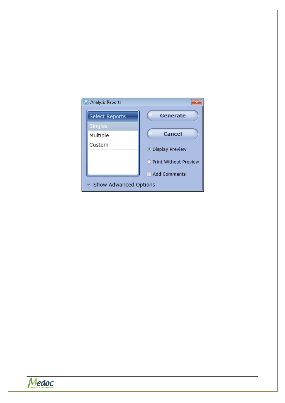
AlgoMed Technical Reference Manual
9.3 Print Results and Reports
AlgoMed program has a powerful Analysis and Results Report Generator that can be
customized for user needs.
Follow these steps to print your results:
1. Select the relevant results file or files from the list in the results screen.
2. Click on the Print button
The following screen is displayed:
Figure 41: Analysis Reports Dialog
3. Configure the Reports options according to your needs.
4. Press on the button of the Report Type you want to use from available options.
Only available reports type are enabled according to your results file selection.
5. Report is generated. Report may have Preview or not according to your preferences.
5.1. Print with Preview
Print Preview is displayed according to the active template and test method.
Press the Print icon or select one of the export options.
5.2. Print without Preview
Report is sent to a connected printer.
Select your Printing preferences according to the available printers and print your
report.
9.3.1 Analysis Report Dialog
The Analysis Report Dialog allows AlgoMed user to generate Reports of AlgoMed tests.
Proprietary 65 of 110
Page 66
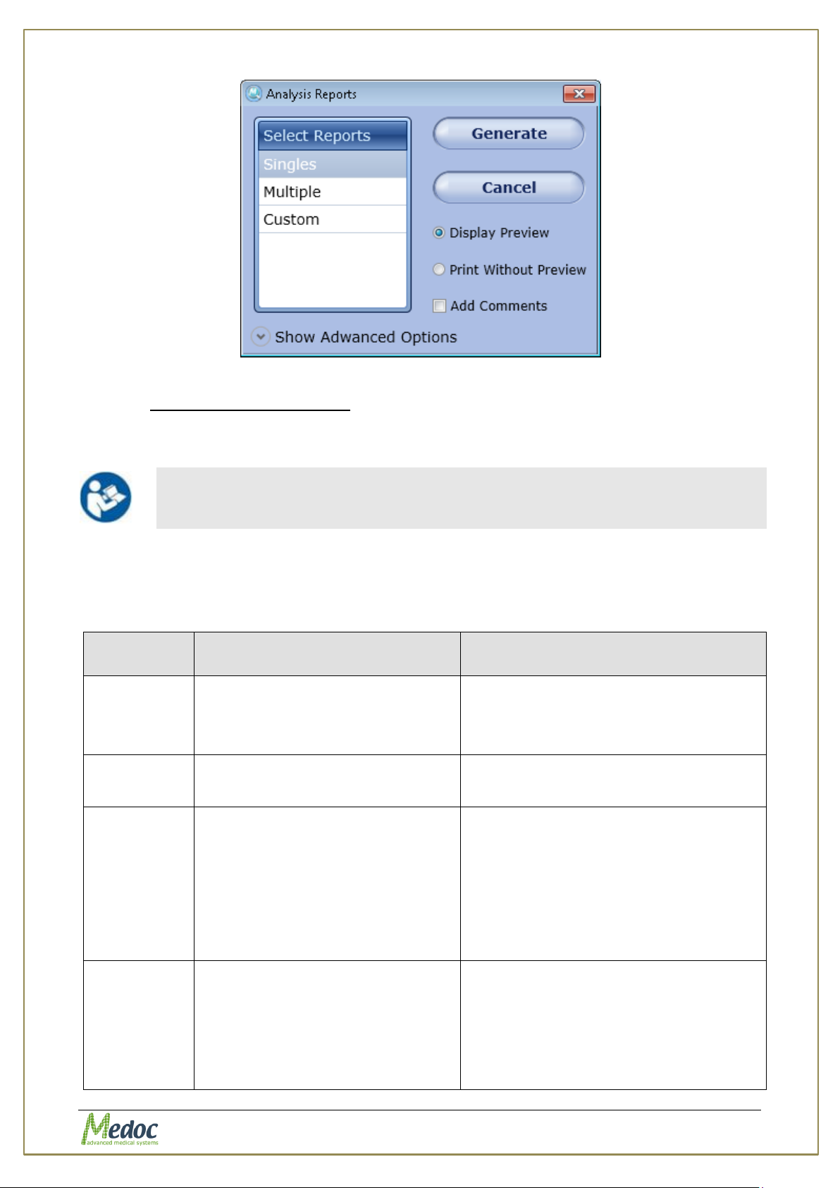
AlgoMed Technical Reference Manual
Report template can be edited and customized according to specific needs.
Refer to 2, page 78 for details
Report
Type
Description
Restrictions
Singles
Simple report which displays the
selected test results. One report
will be generated for each test
results.
None
Multiple
A Statistic summary of results
from more than one test.
1. Test Method:, Limits
2. Selection of 2 or more result files
Bilateral
Compares test statistics for both
sides (left and right) of the same
body site for the same patient.
1. Test Method: Limits
2. Selection of 2 result files
3. Identical Test Subject
4. Identical Test Program
5. Identical Main and Specific body site
6. Opposite body site sides
Site to Site
Compares test statistics for two
different body sites of the same
patient.
1. Test Method: Limits
2. Selection of 2 result files
3. Identical Test Subject
4. Identical Test Program
5. Different Main and / or Specific Site
Figure 42: Analysis Report
9.3.1.1 Analysis Report Type
Report type defines the template and content of the report and analysis to be displayed.
The following templates are available:
Table 14: Report Analysis Configuration
Proprietary 66 of 110
Page 67
AlgoMed Technical Reference Manual
Report
Type
Description
Restrictions
Pre / Post
Compares test statistics from two
separate tests performed at
different times for the same
patient.
1. Test Method: Limits
2. Selection of 2 result files
3. Identical Test Subject
4. Identical Test Program
5. Identical Body Site
Trend
Displays a trend graph from
results of more than one test.
1. Test Method: Limits
2. Selection of at least two test result
files
3. Identical Test Subject
4. Identical Test Program
5. Identical Body Site
Custom
Custom report with custom
analysis and restrictions.
Varies according to report analysis.
Contact Medoc Service for further
details.
Proprietary 67 of 110
Page 68
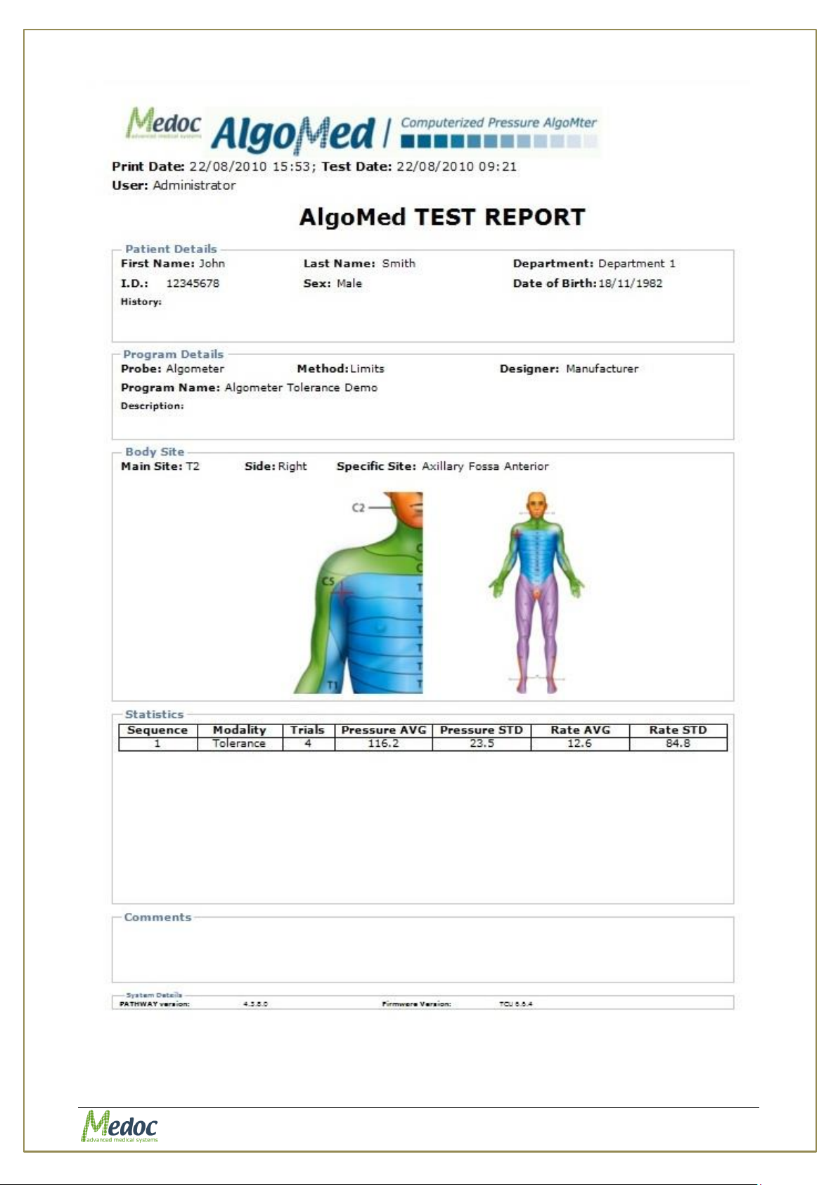
AlgoMed Technical Reference Manual
Figure 43: Algometer Example of Single Report
Proprietary 68 of 110
Page 69
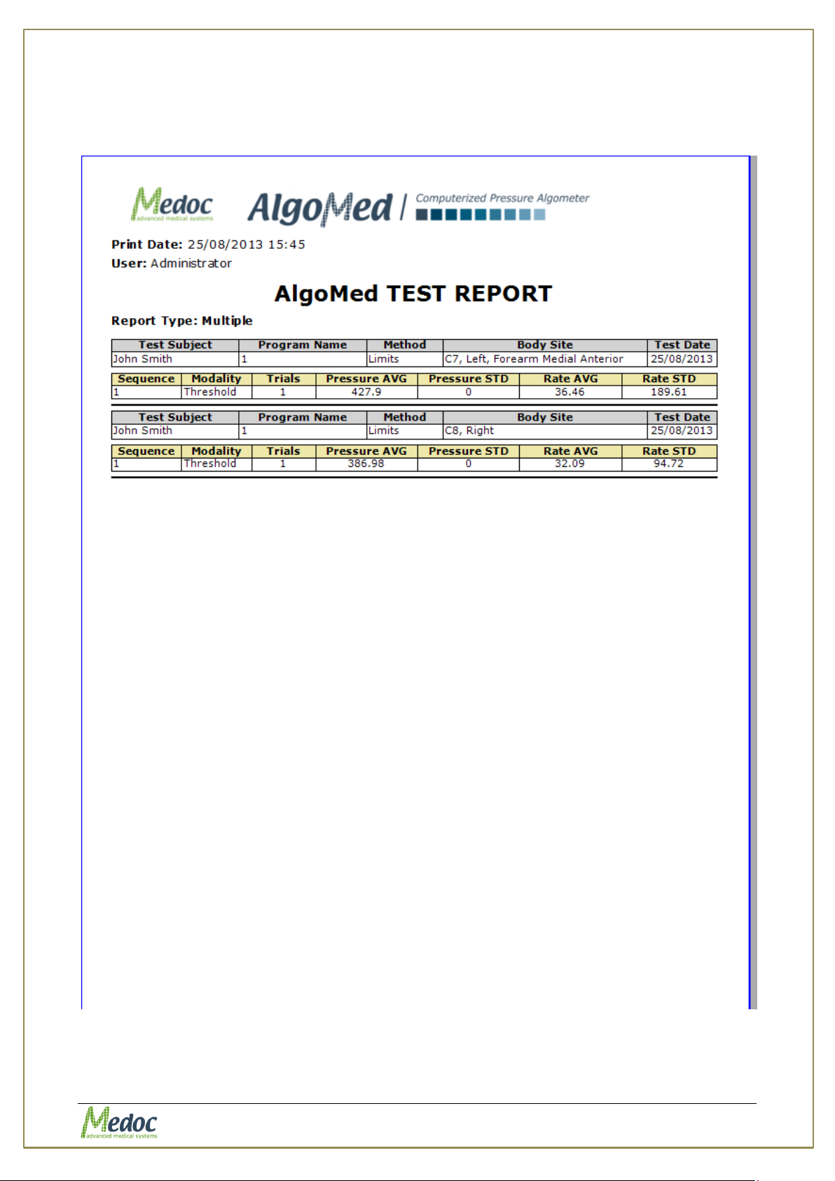
AlgoMed Technical Reference Manual
Figure 54: Algometer Example of multiple Report
Proprietary 69 of 110
Page 70
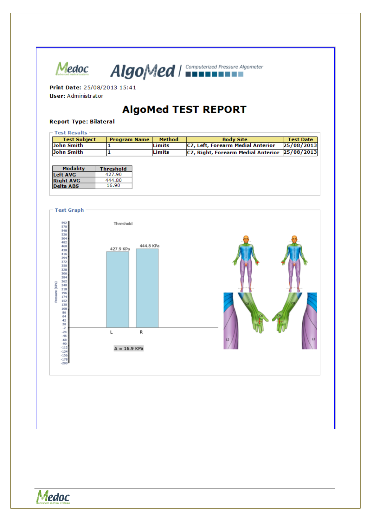
AlgoMed Technical Reference Manual
Figure 44: Algometer Example of Bilateral Report
Proprietary 70 of 110
Page 71
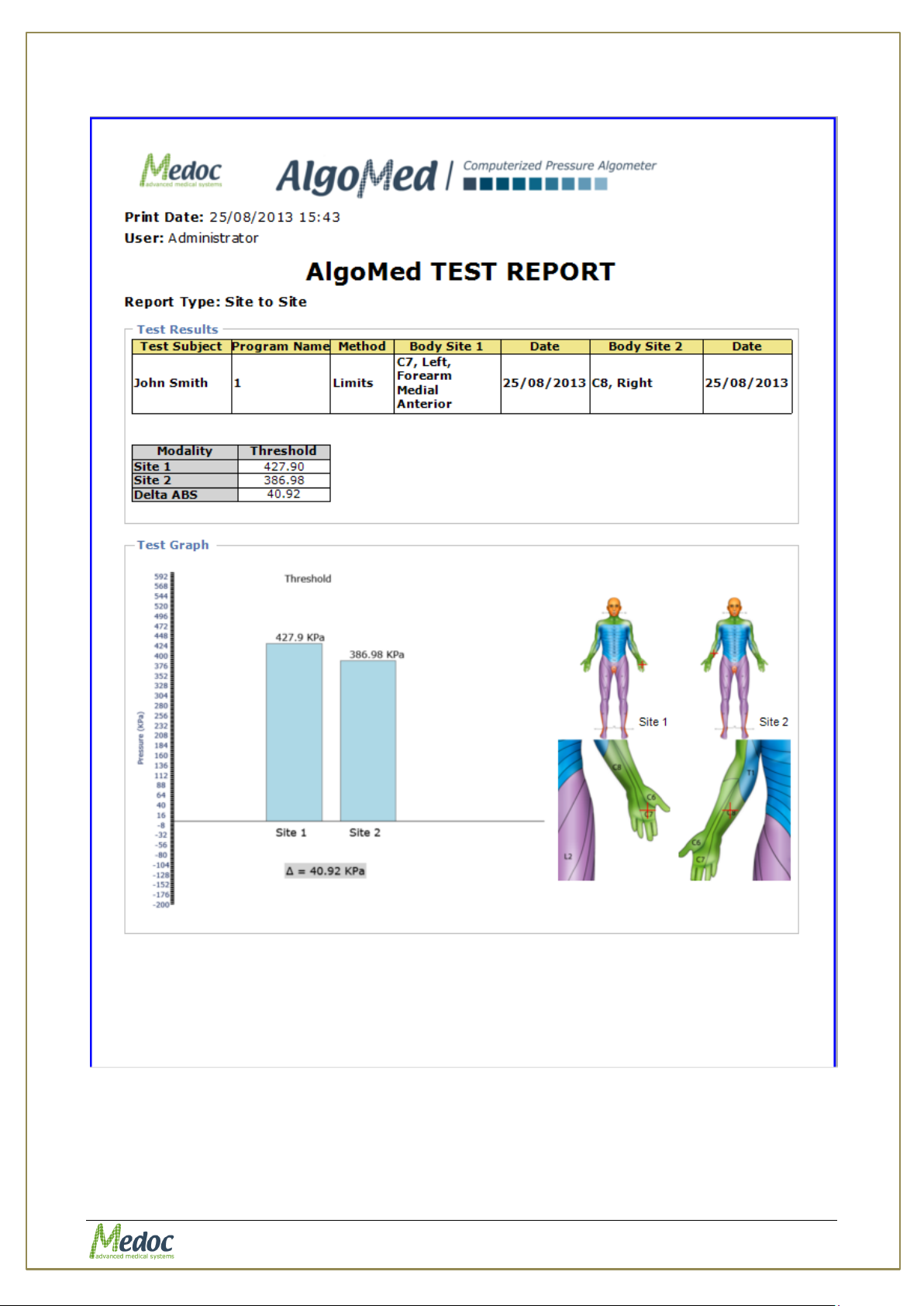
AlgoMed Technical Reference Manual
Figure 56: Algometer Example of Site to Site Report
Figure 57: Algometer Example of PrePost Report
Proprietary 71 of 110
Page 72
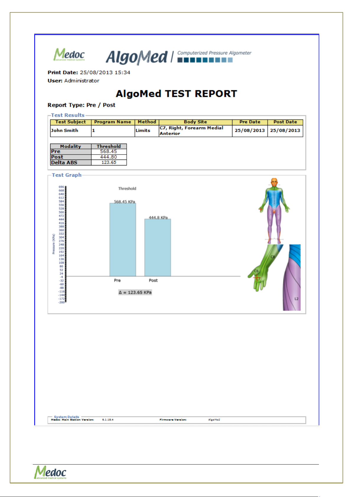
AlgoMed Technical Reference Manual
Proprietary 72 of 110
Page 73
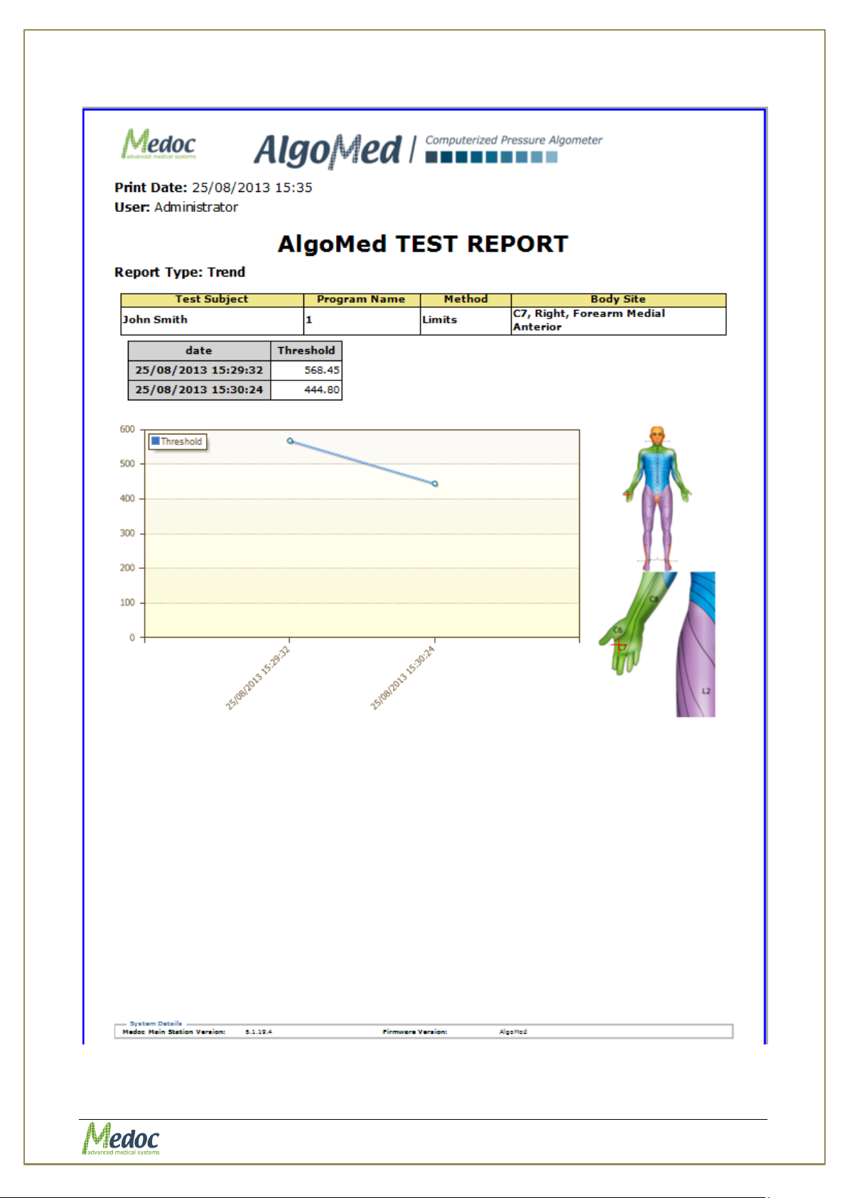
AlgoMed Technical Reference Manual
Figure 58: Algometer Example of Trend Report
Proprietary 73 of 110
Page 74
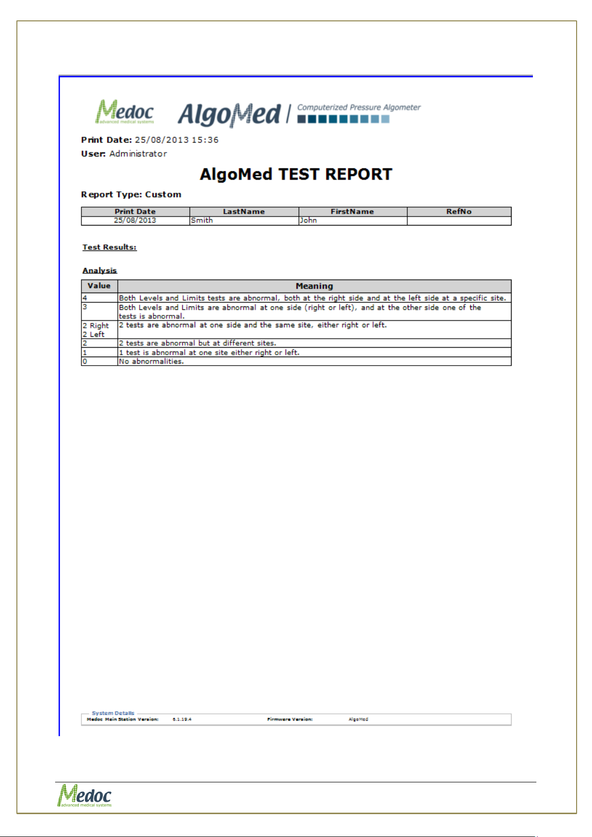
AlgoMed Technical Reference Manual
Figure 59: Algometer Example of Custom Report
Proprietary 74 of 110
Page 75
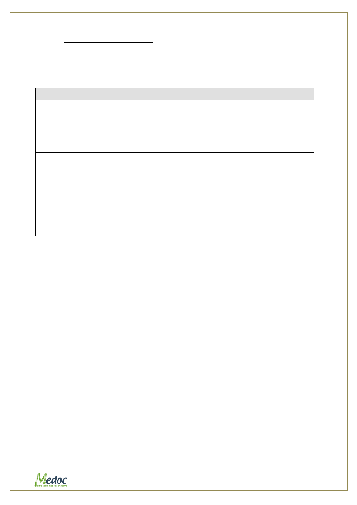
AlgoMed Technical Reference Manual
Parameter
Description
Display Preview
Displays report preview before sending to print.
Print Without
Preview
Send report to print without a preview.
Mode
Automatic Mode – automatically calculate test graph display
Manual Mode – Not relevant for Algometer
Number of Trails
Determine how many trails to display for trail based tests.
Available for Limits and Levels in Manual mode.
Start Time
Not relevant for AlgoMed
End Time
Not relevant for AlgoMed
Min. Temp.
Not relevant for AlgoMed
Max. Temp.
Not relevant for AlgoMed
Add Comments
Allow adding comments for the generated report.
Available for all report type beside Singles.
9.3.1.2 Reports Configuration
Report configurations allow defining basic reports settings and display options.
The following configurations are available:
Table 15: Report Analysis Configuration
Proprietary 75 of 110
Page 76
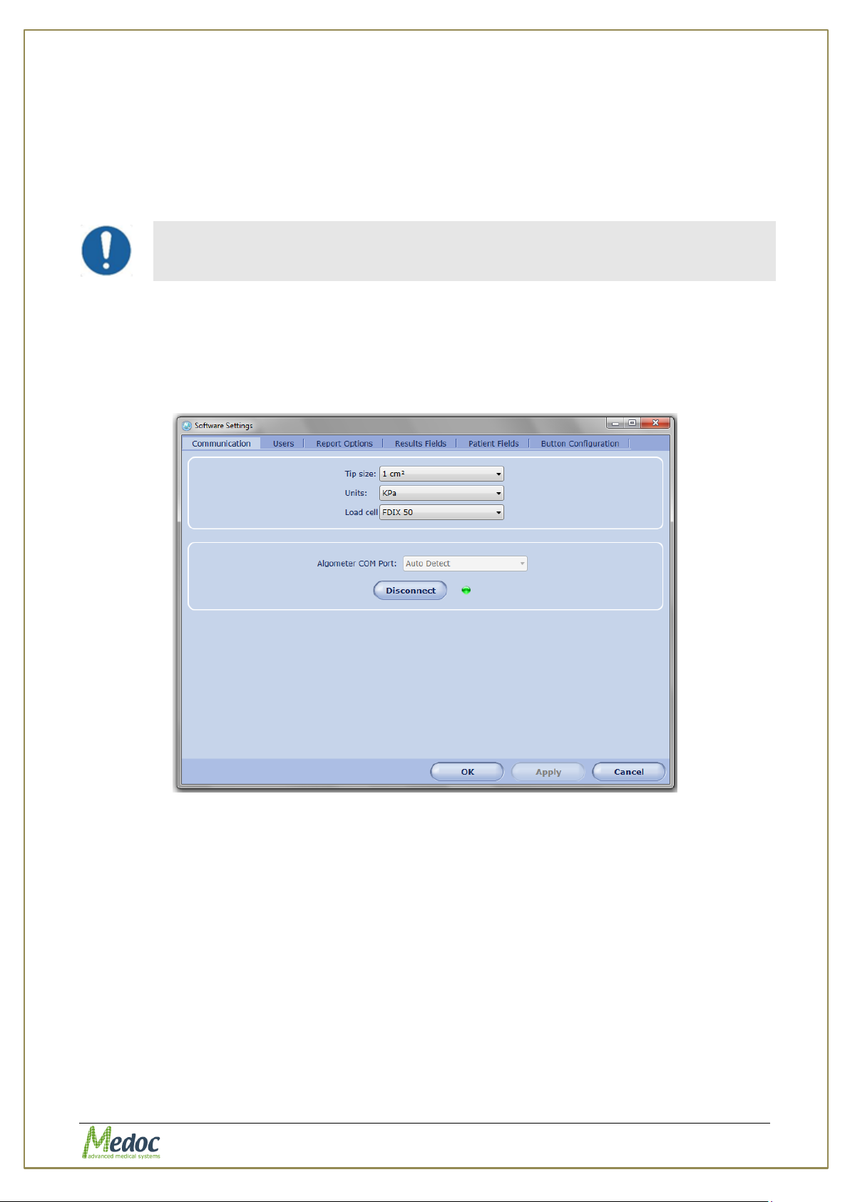
AlgoMed Technical Reference Manual
System configuration is allowed according to software authorization levels.
Refer to section 10.1.5, page 82.
10. System Configuration
AlgoMed system configuration is performed via three different settings:
1. Software Settings
2. Hardware Settings
3. Test Setting
10.1 Software Settings
This function is used to set up the user interface with the software.
To access the software settings screens, from the Settings option in the menu bar; select
Software settings.
The following screen is displayed:
Figure 45: Software Settings Dialog
The following options exist:
communication
Patient’s fields
Results Field
Report Options
Buttons Configuration
users
Proprietary 76 of 110
Page 77
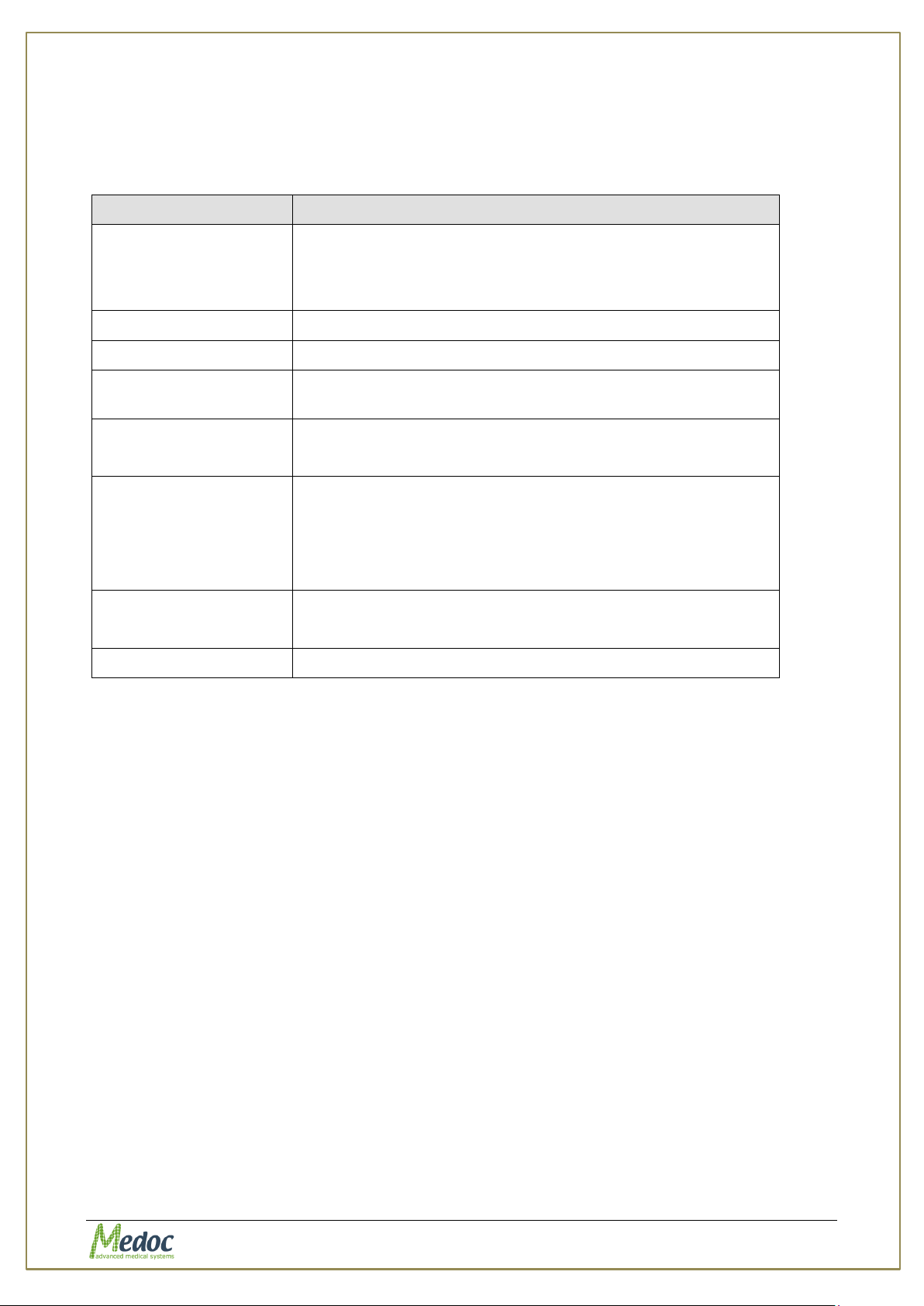
AlgoMed Technical Reference Manual
Parameter
Description
Main Station
Sets the name of the station (computer) on which the Main
Station is installed (possible also from the Viewing Station).
Clicking the This machine button, enters the name of the
current computer.
COM Port.
Not relevant for AlgoMed
Calibration COM Port
Not relevant for AlgoMed
Database server
name
Display the path of the database server, where all software
data is stored (including patients, programs, tests, etc.).
Tip size
Future option for setting the size of the Algometer tip
Set by default to 1 cm2
Units
Set Pressure units. The supported units are :
KPa (default)
Kgf/cm2
Lbf/in2
Load cell
Future option for seting AlgoMed Model
Set by default to FDIX 50
Algometer COM Port
Select the communication port for the Algometer
10.1.1 Communication
The AlgoMed Software Settings screen enables you to set the general software parameters and
Algometer software parameters (see X Figure 45 above):
Table 16: Software Settings - General
Proprietary 77 of 110
Page 78
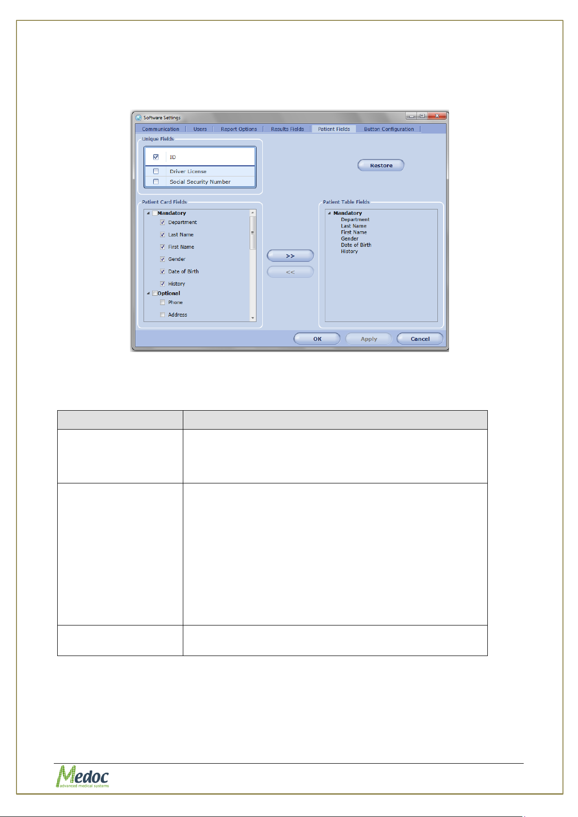
AlgoMed Technical Reference Manual
Parameter
Description
Unique Fields
The marked fields are used for conclusive patient
identification (more than one can be used). Any other field
can be repeated in various patients (for example, John can
appear as first name for more than one patient).
Patient Card Fields
The marked fields are displayed in the patient details
dialog.
1. Mandatory fields – used for patient identification and
cannot be deleted (unselected)
2. Optional fields – built in commonly used fields that can
be added / removed from patient card by check /
uncheck the field
3. User Defined fields – custom fields that can be edited
according to requirement and then added / removed
from patient card by check / uncheck the field
Patient Table Fields
The fields which are displayed in the patient list and can be
searched by.
10.1.2 Patient Fields
This dialog configures the displayed fields in the patient details dialog and patient table.
Figure 46: Patient Fields Configuration Screen
Table 17: Patient’s Field
To define and add Patient Card Fields to the Patient Details dialog:
1. From the Patient Card Fields list, select the required field or add field name.
2. Click the Apply button.
To add Patient Fields to Patient Table:
1. Select field to be added from the Patient Card Fields list.
Proprietary 78 of 110
Page 79
AlgoMed Technical Reference Manual
2. Click the button to add field to Patient Table Fields.
3. Click the Apply button.
To remove Patient Fields from Patient Table:
1. Select field to be removed from the Patient Table Fields list.
2. Click the button to remove field from Patient Table Fields.
3. Click the Apply button.
To restore the default Patient Fields:
1. Click the Restore button to restore default Patient Fields.
2. Click the Apply button.
Proprietary 79 of 110
Page 80
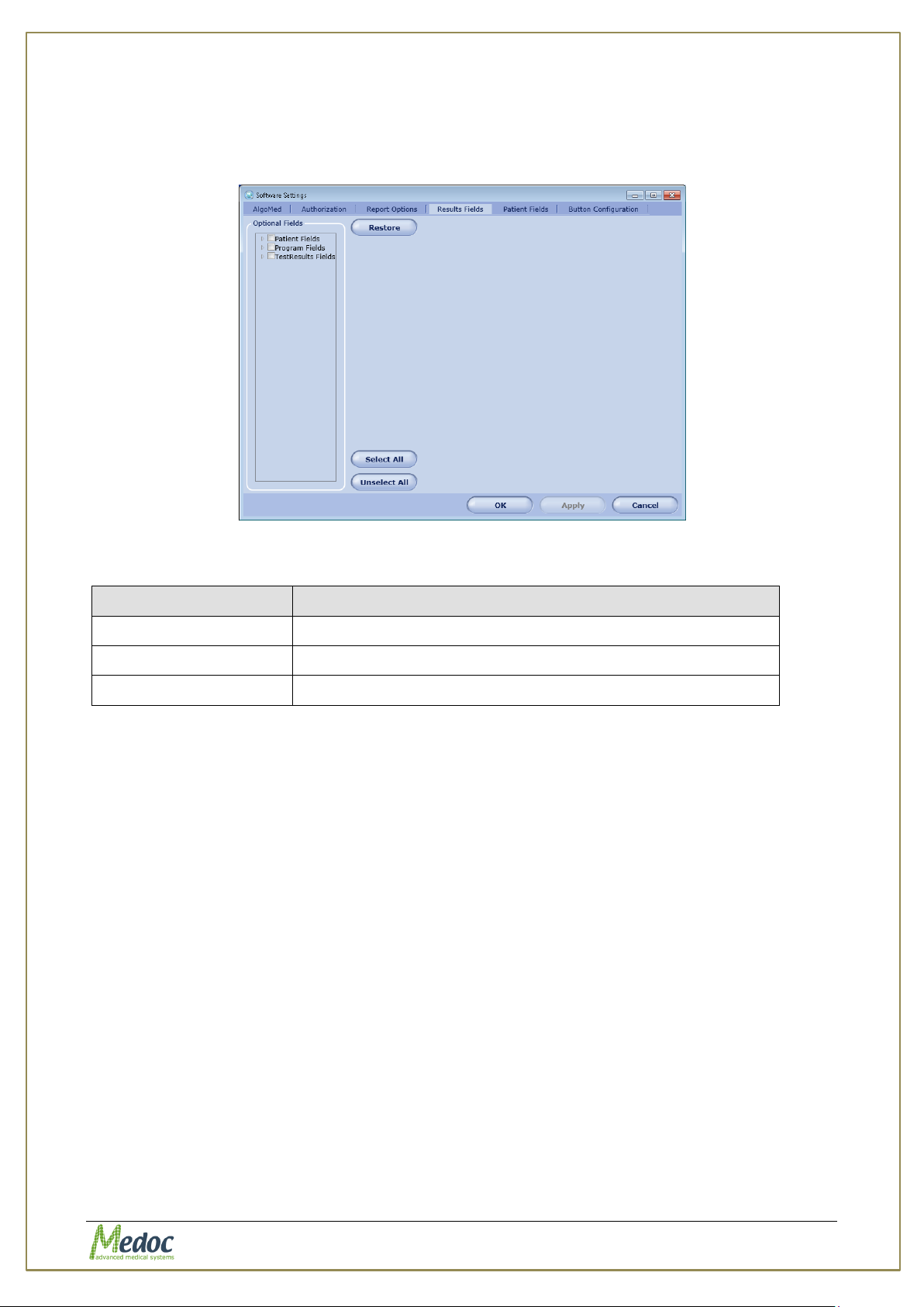
AlgoMed Technical Reference Manual
Parameter
Description
Patient Fields
Available fields from patient card
Program Fields
Program related fields
Test Results Fields
Test related fields
10.1.3 Results Fields
This dialog configures the displayed fields in the Results list.
Figure 47: Results Fields Configuration Screen
Table 18: Patient’s Field
To add field to the Results Table:
1. From Optional Fields list, select (check) field to be added to Results Table.
2. Click the Apply button.
To remove field from the Results Table:
3. In Optional Fields list, uncheck field to be removed from Results Table.
4. Click the Apply button.
To restore the default Results Fields:
1. Click the Restore button to restore Results Fields defaults.
2. Click the Apply button.
10.1.4 Report Options
AlgoMed software enables to generate test reports, which contain the test results and data
according to the system definitions when the test was saved.
AlgoMed test has a unique report template, which is used when the user selects to print the
test results.
Proprietary 80 of 110
Page 81
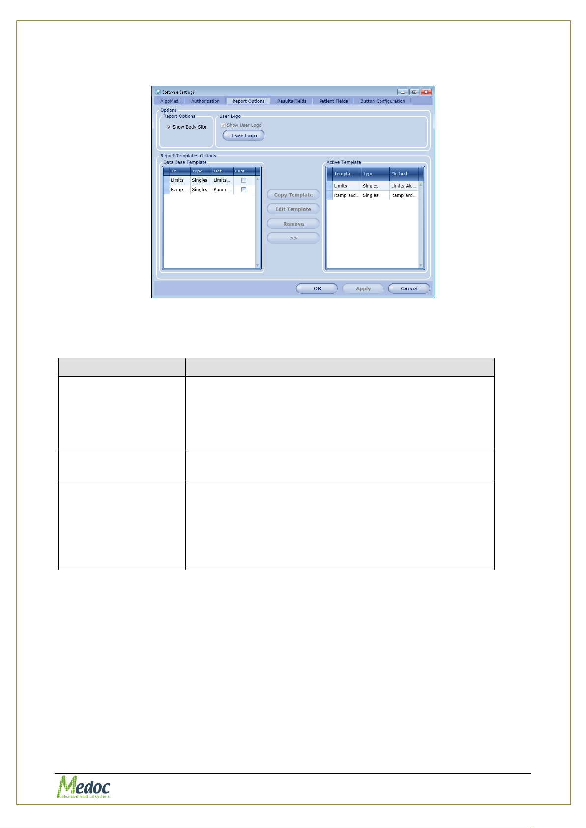
AlgoMed Technical Reference Manual
Parameter
Description
Report Options
Enables selection between two types of reports:
1. Detailed Report
1.1. Configure body site display using check box
2. Simple Print (basic information only)
User Logo
Enables and configure display of customized user Logo to
the report printouts
Report Templates
Options*
Enables editing Detailed Report templates:
1. Manage Report templates data base
2. Edit custom made reports
3. Manage Active Templates list
* Available Only when Detailed Report Option is selected
The Report Options tab enables PAHTWAY users to manage their reports and edit reports
templates.
Figure 48: Report Options tab
Available Options:
Table 19: Report Options
Proprietary 81 of 110
Page 82
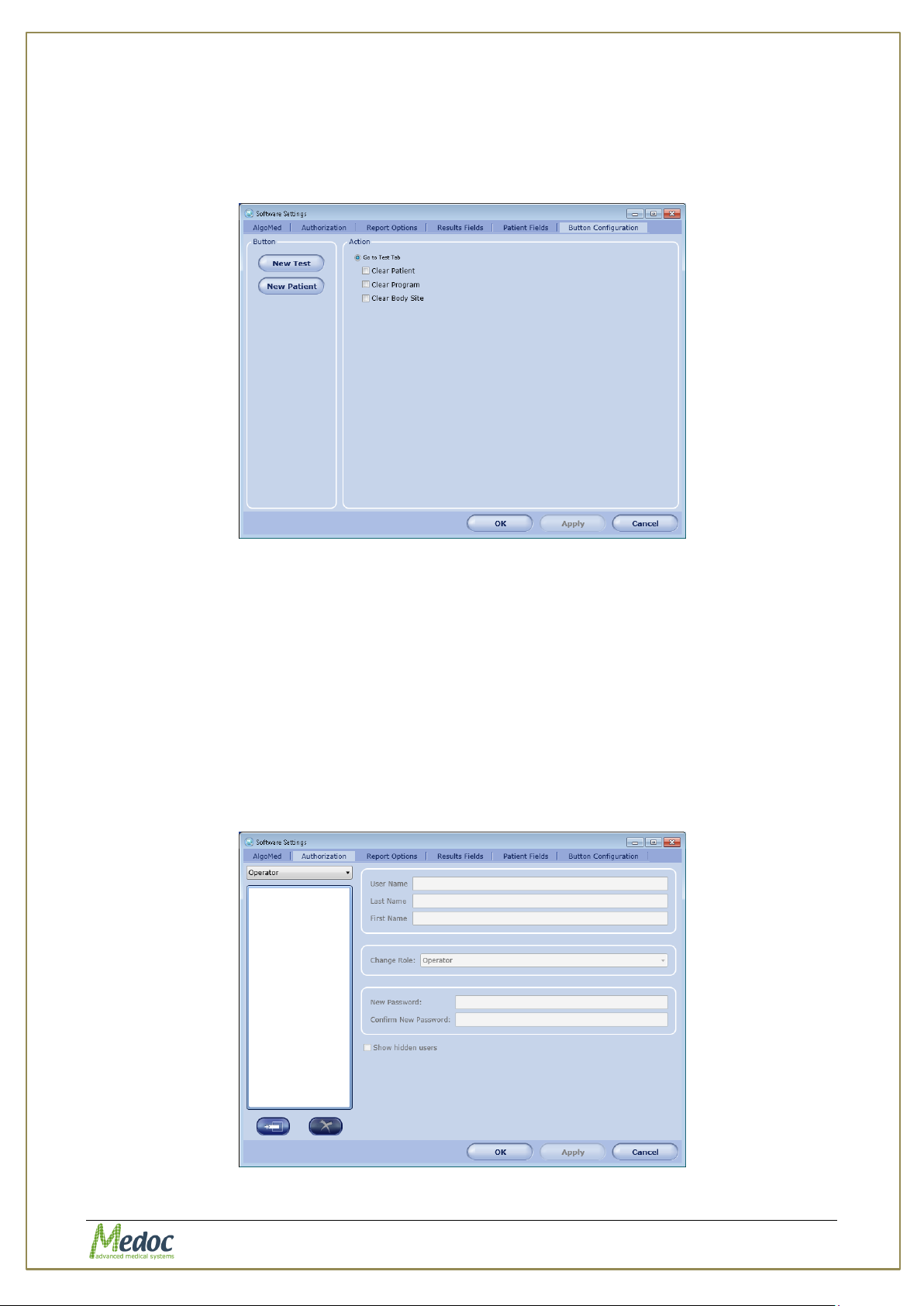
AlgoMed Technical Reference Manual
10.1.5 Buttons Configuration
This dialog enables action customization for various buttons in the AlgoMed software according
to user requirement.
Figure 49: Buttons configuration Software Settings
To customize button settings:
1. Select button to be customized from the Button list.
2. Select button Action from the available options.
3. Click the Apply button.
10.1.6 Users
The AlgoMed software can restrict user capabilities according to their authorization level.
There are four authorization levels in the AlgoMed software: Software Administrator;
Biomedical Engineer; Medical Supervisor; Operator.
This dialog sets the authorization level for the AlgoMed users.
Figure 50: User Authorization Software Settings
Proprietary 82 of 110
Page 83
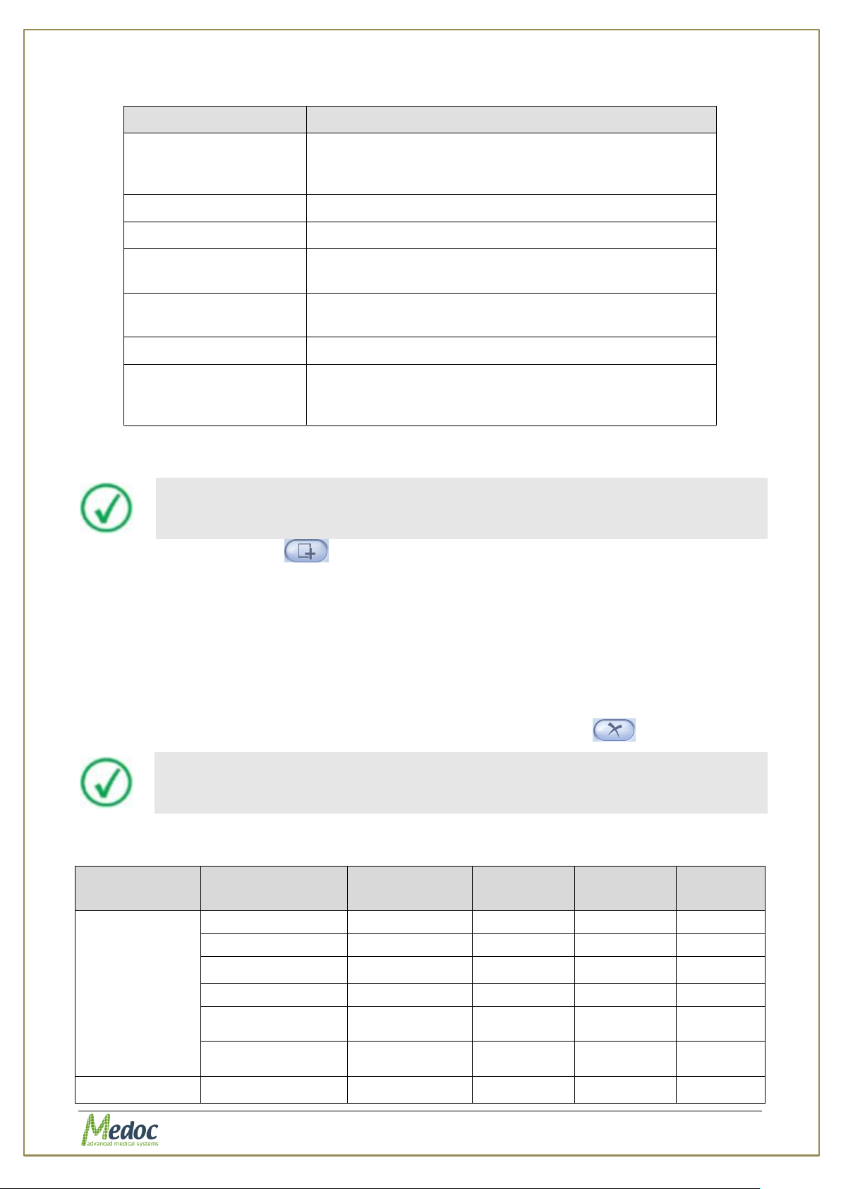
AlgoMed Technical Reference Manual
Parameter
Description
User name
The username, by which the user will be logged into
the system, and by which the user will be sorted by
other users.
Last name
The user’s last name.
First name
The user’s first name.
Change role
Drop-down menu for changing the user’s authorization
level.
New password
The password, by which the user is to log into the
system.
Confirm password
Password confirmation field.
Show hidden users
Enable viewing of unauthorized users that do not exist
in the current database or imported programs, but
exist only as a result of a retrieved database.
A user can create only equal or lower level authorized user.
See Table 17 for details regarding each authorization level capabilities.
Screen
Function
Software
Administrator
Biomedical
Engineer
Medical
Supervisor
Operator
Patient
Add Patient
√
√ √ √
Edit Patient
√
√ √ √
Delete patient
√
√
√
X
Add Department
√
√ √ √
Delete
Department
√
X √ X
Rename
Department
√
X √ X
Programs
Add Program
√
√
√
X
Table 20: Authorization parameters
In order to create AlgoMed user follow these instructions:
1. Click the add user button at the bottom of the user list.
2. Enter the relevant information, according to the table above.
3. From the Change role drop-down menu, select the required authorization level.
4. If you want to change the user’s authorization level, select the required user from the list;
then from the Change role drop-down menu, choose the required authorization level.
5. Click the Apply button.
6. Click the OK button.
7. To remove a user from an authorization list, click the remove button .
Table 21: Authorization Levels (main actions)
Proprietary 83 of 110
Page 84
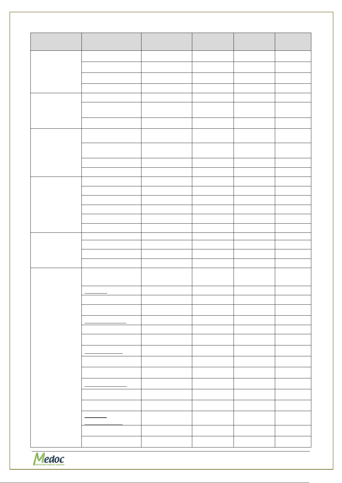
AlgoMed Technical Reference Manual
Screen
Function
Software
Administrator
Biomedical
Engineer
Medical
Supervisor
Operator
Edit Program
√
√
√
X
Delete Program
√
√
√
X
Duplicate Program
√
√
√
X
Program Preview
√
√ √ √
Results
View Graph
√
√ √ √
View Program
Details
√
√ √ √
Delete
√
X √ X
Test
View Patient
Details
√
√ √ √
View Program
Details
√
√ √ √
Clear √ √ √ √
Go to Test…
√
√ √ √
Tool bar - File
Export √ √ √ √
Import √ √ √ √
Export to Excel
√
√ √ √
Print √ √ √ √
Log Off √ √ √ √
Exit √ √ √ √
Tool bar View
Test √ √ √ √
Patient √ √ √ √
Programs
√
√ √ √
Results √ √ √ √
Tool bar Settings
Software
Settings
General
View √ √ √ √
Edit √ √
√
X
Patient’s fields
View √ √ √ √
Edit √ √
√
X
Results fields
View √ √
√
√
Edit √ √
√
X
Report options
View √ √
√
√
Edit √ √
√
X
Buttons
configuration
View √ √
√
√
Edit √ √
√
X
Proprietary 84 of 110
Page 85
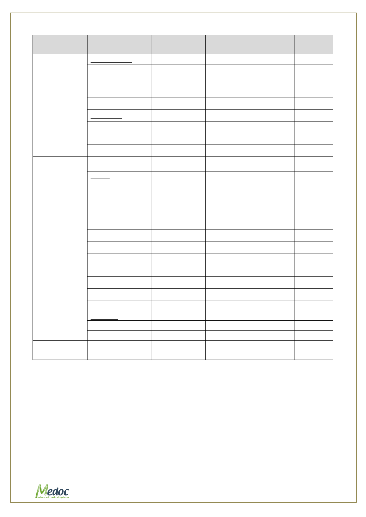
AlgoMed Technical Reference Manual
Screen
Function
Software
Administrator
Biomedical
Engineer
Medical
Supervisor
Operator
Authorization
View √ √ √ √
Add √ √
√
X
Edit √ √
√
X
Delete √ √
√
X
Algometer
View √ √
√
√
Edit √ √
√
x
Connect
√
√
√
√
Hardware
settings
CoVas
(calibration)
√
√
√
Tool bar Utilities
Test
Instructions
√
√ √ √
Department
View
√
√
√
√
Edit
√
√
√
X
Normative data
View
√
√
√
√
Edit
√
√
√
X
Delete
√
√
√
X
Import/Export
√
√
√
X
Black Box
Software
View √ √ √ √
Export √ √ √ √
Tool bar Help
About… √ √ √ √
10.2 Hardware Settings
This menu enables you to set up and test the parts of the system hardware. This can include
setting up CoVas system.
CoVAS calibration is required whenever a new CoVAS is connected to the system.
To perform CoVAS calibration, perform the following procedure:
1. Connect the CoVAS device using its USB cable to a USB COM in your computer.
2. From the Settings menu, select the Hardware Settings option.
3. The following screen is displayed:
Proprietary 85 of 110
Page 86
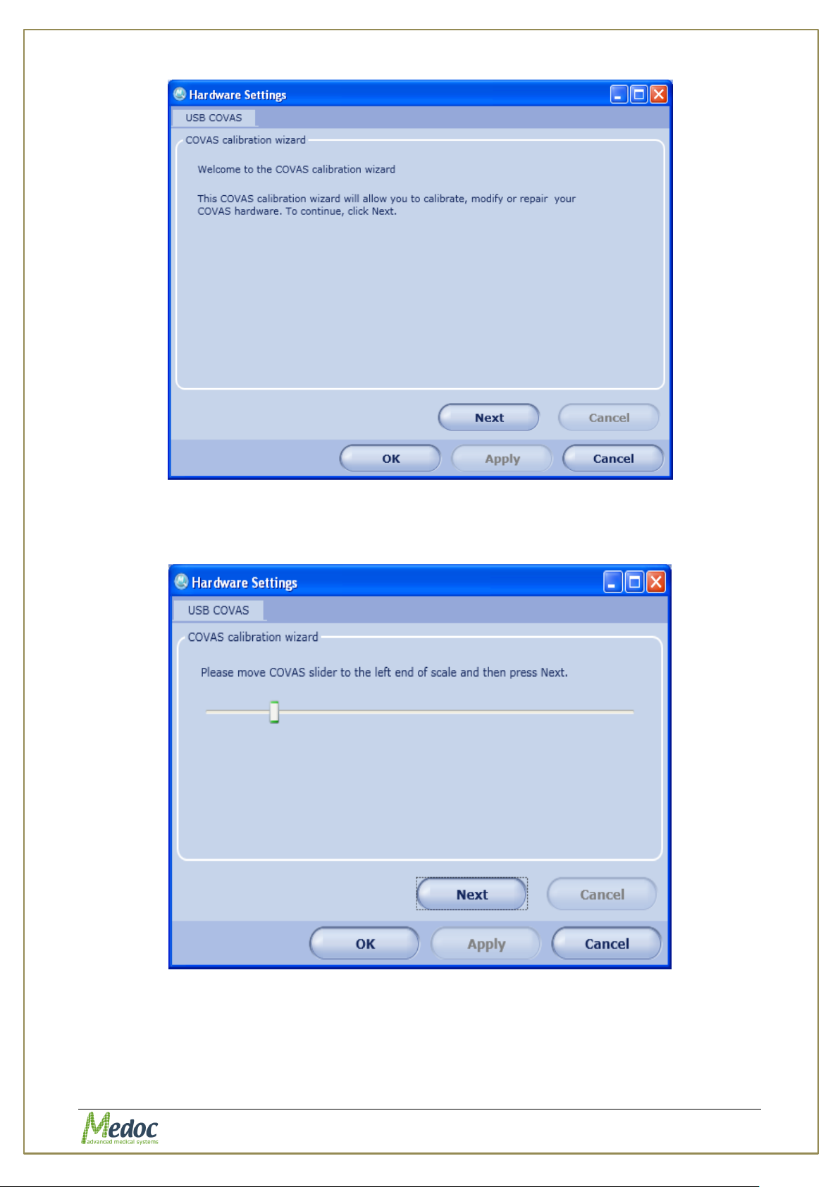
AlgoMed Technical Reference Manual
4. Click the Next button.
The following screen is displayed:
Figure 51: CoVas calibration
Figure 52: CoVAS calibration wizard
5. Move the CoVAS slider all the way to the left.
Click the Next button.
The following screen is displayed:
Proprietary 86 of 110
Page 87
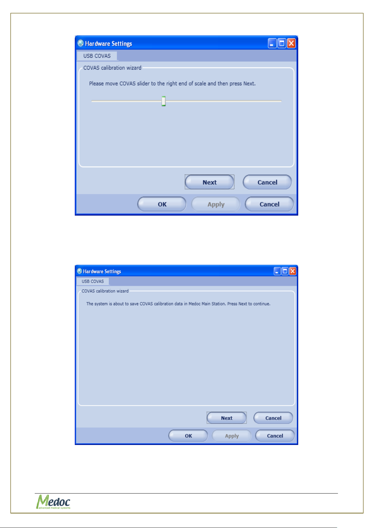
AlgoMed Technical Reference Manual
Figure 53: CoVAS Slider Calibration
6. Move the CoVAS slider all the way to the right.
Click the Next button.
The following screen is displayed:
Figure 54: CoVAS Calibration Results
7. Click Next to save the calibration results.
The following screen is displayed:
Proprietary 87 of 110
Page 88
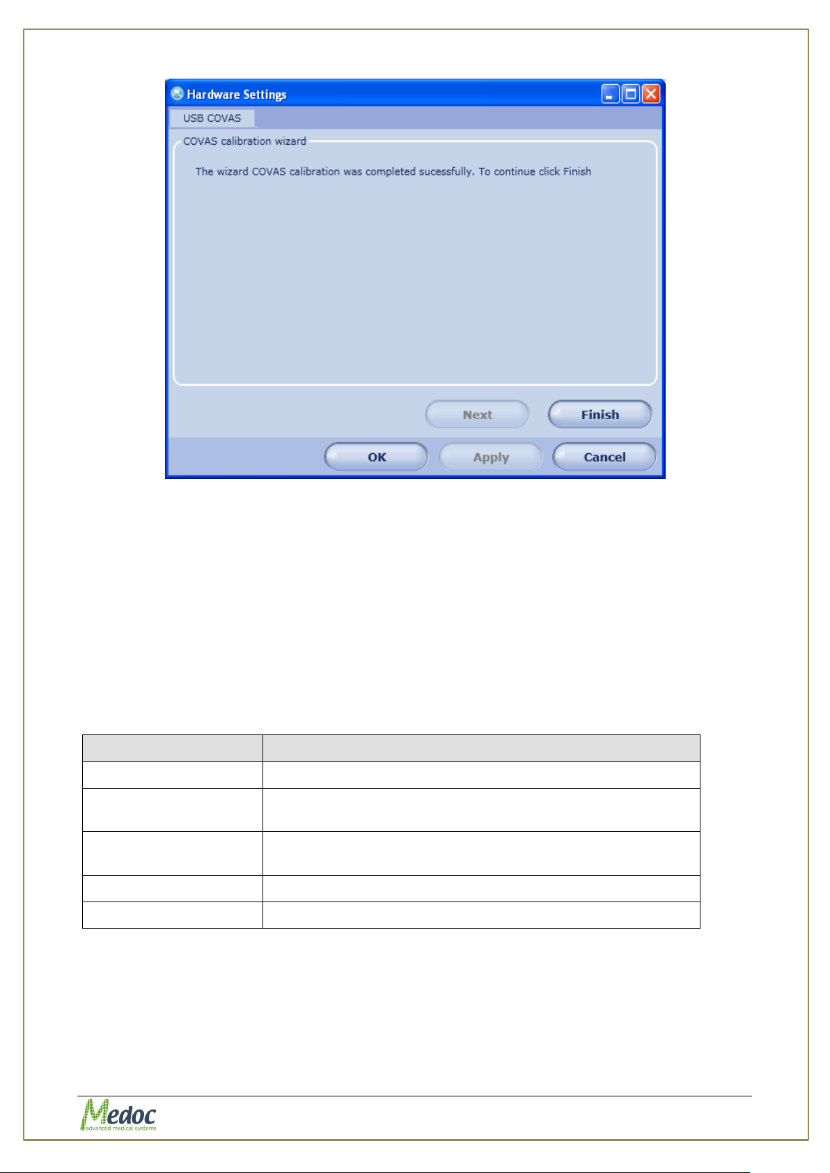
AlgoMed Technical Reference Manual
Parameter
Description
Test Configuration
Configure Test display settings
Instructions
Configuration
Configure and manage global test instructions
Event Sound
Configuration
Define customs sounds to mark events
Event Marker
Define custom messages to mark event
Body Sites
Configure custom body sites
Figure 55: CoVAS Calibration Finish Screen
8. Click the Finish button to complete the calibrating process; then click OK.
10.3 Test Settings
Test settings enable you to set up the basic test settings for all tests run on the current
system.
To access the Test Settings dialog select Test Settings from the Settings menu on the top
menu bar.
The following options are available:
Table 22: Test Settings Options
Proprietary 88 of 110
Page 89
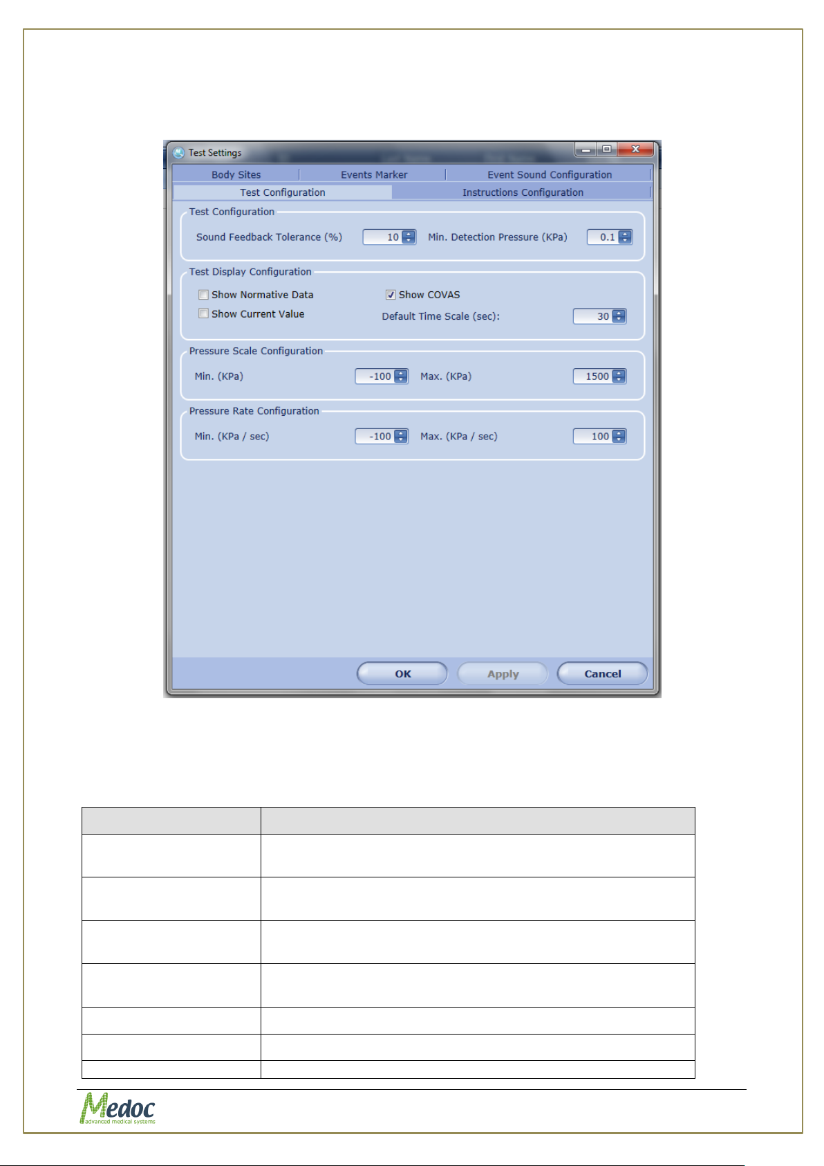
AlgoMed Technical Reference Manual
Parameter
Description
Sound Feedback
Tolerance
Define margins in percentage to sound feedback to be
display and heard
Min. Detection
Pressure
Minimum Pressure to be detect by software
Show CoVAS
View/Hide CoVAS display. CoVAS display is currently not
available for the AlgoMed system.
Show Normative
Data
Currently not available for AlgoMed
Default Time Scale
Default time display on screen
Show Current Value
Display pressure value in real time
Pressure scale
Default pressure range display (min, max) for Algometer
10.3.1 Test Configuration
The Test Configuration option enables you to set default test display parameters.
Figure 56: Test Configuration Settings
The available settings are described in the table below:
Table 23: Test Settings Options
Proprietary 89 of 110
Page 90
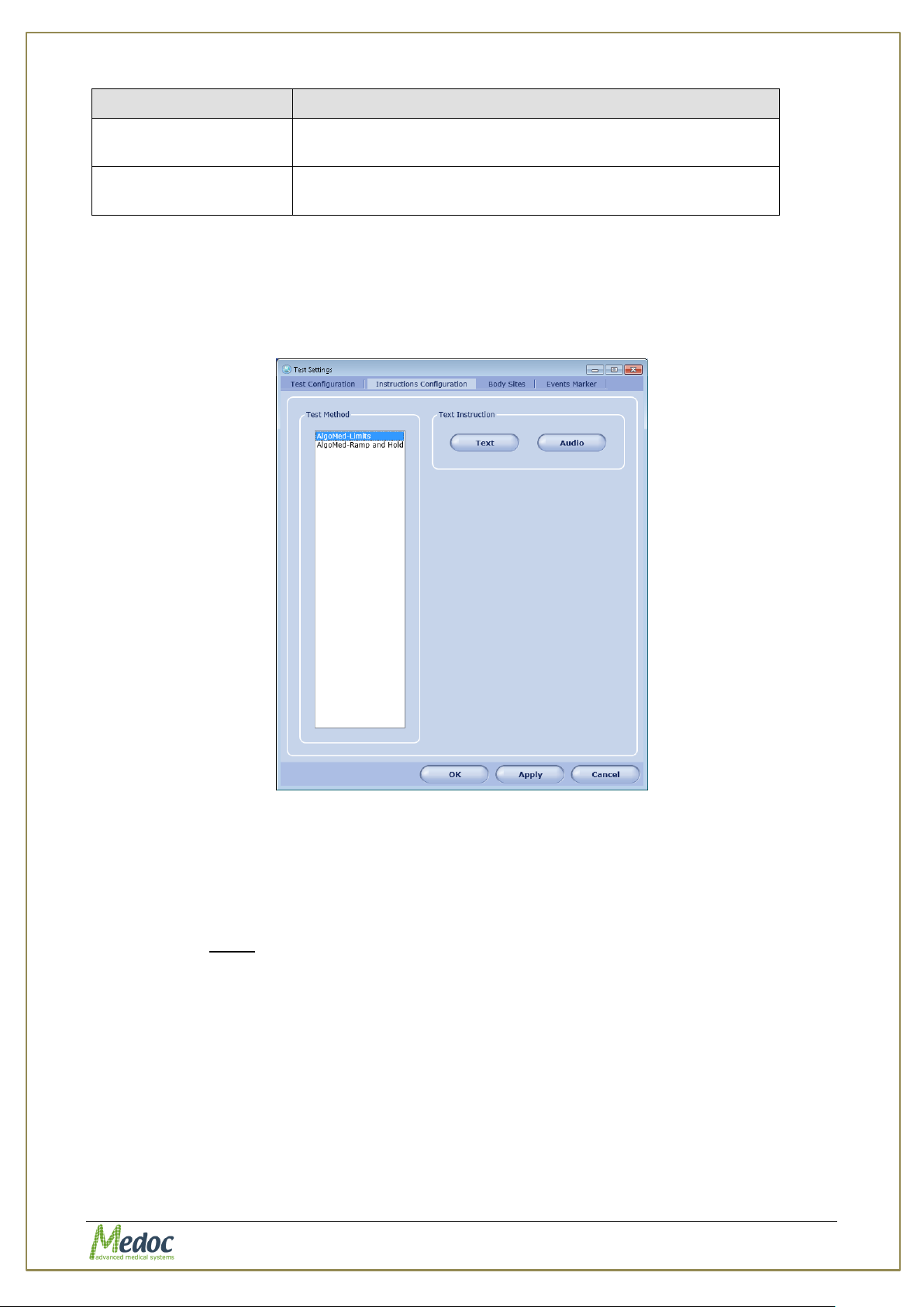
AlgoMed Technical Reference Manual
Parameter
Description
configuration
test screen and gage. Units depend in current user
settings.
Pressure Rate
configuration
Default pressure rate display (min, max) for Algometer
gage. Units depend on current user settings.
10.3.2 Instructions Configuration
The Instructions Configuration option sets the default text and audio instructions according to
test method. These instructions will be associated by default to each new program created
based on the test method. To configure custom instructions for a specific program (refer to
section 2).
Figure 57: Instructions Configuration
Test instructions are available in the following formats:
Text – written instructions.
Audio – vocal recording which will be played out to the patient. Supported file formats
are: wav, wma or mp3.
10.3.2.1 Text
To create written instructions for a test method:
1. Choose the desired test method for example AlgoMed-Limits.
2. Click the Text button.
The following screen is displayed:
Proprietary 90 of 110
Page 91
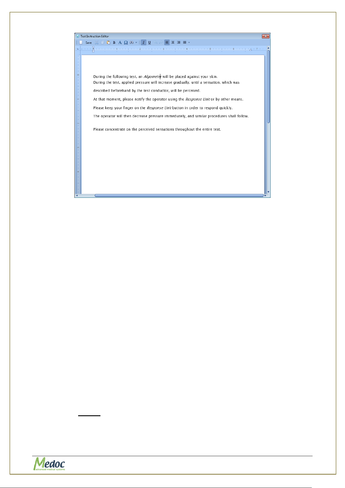
AlgoMed Technical Reference Manual
Figure 58: Test Instructions Editor
3. Edit the required text.
4. Click the Save button.
5. Close the window by clicking OK.
The following formatting functions are available:
New – clears the entire document for entering new instructions.
Save – saves the entered text.
Cut – cuts the selected text from the section to a virtual clipboard. The proceeding text
moves back to fill the blank space.
Copy – copies the selected text to a virtual clipboard.
Paste – pastes the text currently in the virtual clipboard to the location of the cursor.
B – Turns the selected text to bold typeface.
Find – invokes a text-locating tool.
I – turns the selected text to italicized typeface.
U – Underlines the selected text.
Undo – undoes the recent entries in the editor.
Redo – redoes the entries that were undone.
Left – left-adjusts the current paragraph.
Center – center-adjusts the current paragraph.
Right – right-adjusts the current paragraph.
10.3.2.2 Audio
To enter vocal instructions for a test method:
1. Create an audio file of the instructions in one of the following formats:
WAV, WMA, MP3
Proprietary 91 of 110
Page 92
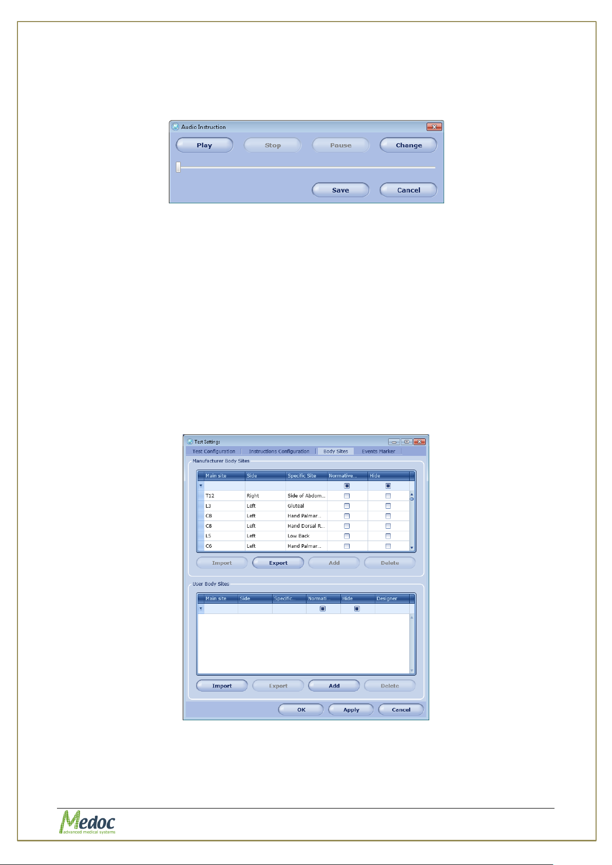
AlgoMed Technical Reference Manual
2. Choose the desired test method for example AlgoMed-Ramp and Hold.
3. Browse to the audio recording folder, and select the audio file.
4. Click the Open button.
Figure 59: Audio save button
5. Click the Save button.
6. Close the window.
The following functions are available:
Play – Plays the audio file.
Stop – Stops the playback. Play will start from the beginning.
Pause – Pauses playback. Play will continue from paused place.
Change – Reopens browser to allow replacing the current file with another
one.
10.3.3 Body Site Editor
The Body Site Editor option displays the complete Body Sites list as set by the Manufacturer,
and enables the user to create a personal list of tested body sites.
Figure 60: Body Sites Editor
The Body Site Editor is divided into two sections:
1. Manufacturer Body Sites
2. User Body Sites
Proprietary 92 of 110
Page 93

AlgoMed Technical Reference Manual
10.3.3.1 Manufacturer Body Sites
The Manufacturer Body Sites section displays the complete list of body sites (Dermatomic
areas) as set by the manufacturer.
The following information is available:
1. Main Site – C1…C8; T1…T12; L1…L5; S1…S5.
2. Side – Left or Right.
3. Secondary Site – matches the Dermatomic areas.
4. Normative Data – indicates if relevant normative data is available in the Normative Data
list.
5. Hide – enables the user to hide a site from the Body Site selection screen.
To narrow down the displayed list use the filter row.
The following actions are available in the Manufacturer Body Sites Editor:
1. Export Body Site list to an excel file.
2. Import .ats binary Body Site list.
3. Select Hide or Display site in the Body Site selection screen by using the check box.
10.3.3.2 User Body Sites
The User Body site section enables the user to manage a customized Body Site list according
to specific needs.
The following information is available:
1. Main Site – C1…C8; T1…T12; L1…L5; S1…S5.
2. Side – Left or Right.
3. Secondary Site – matches the Dermatomic area.
4. Normative Data – indicates if relevant normative data is available in Normative Data list.
5. Hide – enables the user to hide a site from the Body Site selection screen.
To narrow down the displayed list use the filter row.
The following actions are available in the User Body Sites Editor:
1. Export Body Site list to an excel file.
2. Import Body Site list from an excel file (Compatible files only).
3. Edit Body Site entry.
4. Delete Body Site entry.
5. Select Hide or Display site in the Body Site selection screen by using the check box.
10.3.4 Event Marker
The Event Marker option enables you to create custom messages that can be used to mark
events during the test. The events are also saved with the test and can be viewed when
exporting the test to excel.
Proprietary 93 of 110
Page 94
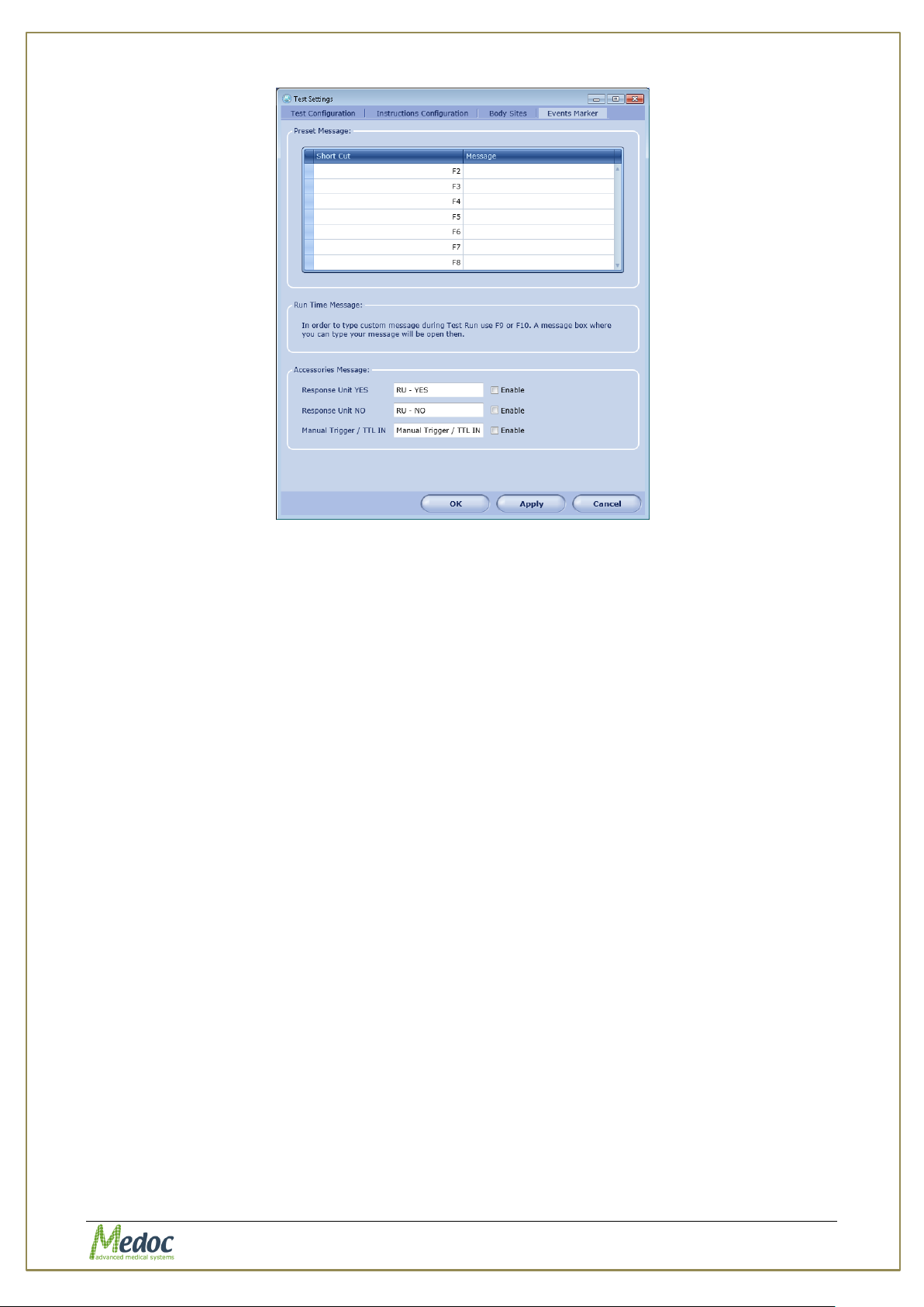
AlgoMed Technical Reference Manual
Figure 61: Event Marker
To use the event markers during a test, press one of the function keys F2 – F10 at the time
the event occurs. Events can be used to mark patient reaction, substance intake and etc.
There are 3 types of event messages that can be defined:
1. Preset Messages: Preset messages allow you to associate custom preset messages with
the function keys F2 – F8. Click the message line next to function key to save a preset
message. Preset message may contain Numbers, Letters and Symbols.
2. Run Time Messages: Run time messages are associated with function keys F9 – F10.
The messages are not pre-defined and can be edited during the test. When pressed during
a test, a dialog box will open enable you to enter a short message. Use Shift+Enter to
start a new line and Enter to close and save the message.
3. Accessories Messages: Currently not available for AlgoMed.
10.3.5 Event Sound Configuration
The Event Sound Configuration option allows you to associate a sound or recording to a
specific event. Event sounds can only be associated with Standard Events and Rate Feedback
(See sections 7.3.1and 7.3.2 for instructions on how to use these events during tests).
Event sounds can be configured for the following events:
1. Standard Events – Currently only the Onset event is available for AlgoMed Tests.
2. Patient Response Unit - Sound played when the Patient Response Unit is pressed.
3. Rate Feedback – Sound played when audio rate feedback is used. The sound can defined
separately for rate lower or higher than required.
Sound effects can be added from the sound effect library available with the software or can
add you own sound files.
Proprietary 94 of 110
Page 95
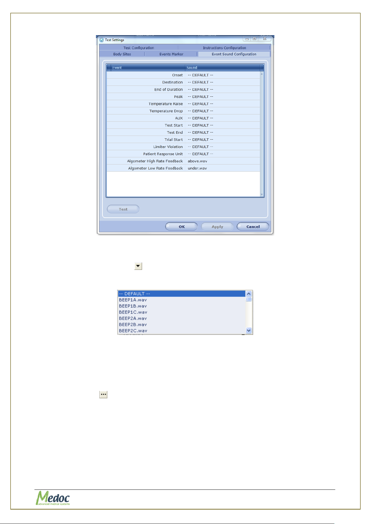
AlgoMed Technical Reference Manual
Figure 62: Event Sound Configuration
To add a sound from the sound effect library:
1. Click the drop-down arrow at the right end of the required event.
The sound effect list is displayed:
Figure 63: Sound effect library
2. Choose the required sound effect. The selected filename will be displayed in the sound
column next to the event.
3. Click the Test button, to listen to the selected sound effect.
To add a custom sound effect:
1. Click the ellipsis at the right end of the required event. Note that long sound files may
affect the test execution.
2. Click the OK button on the warning message dialog.
3. Browse to the required folder, and select the required file. The selected filename will be
displayed in the sound column next to the event.
4. Click the Test button, to listen to the selected sound effect.
Proprietary 95 of 110
Page 96
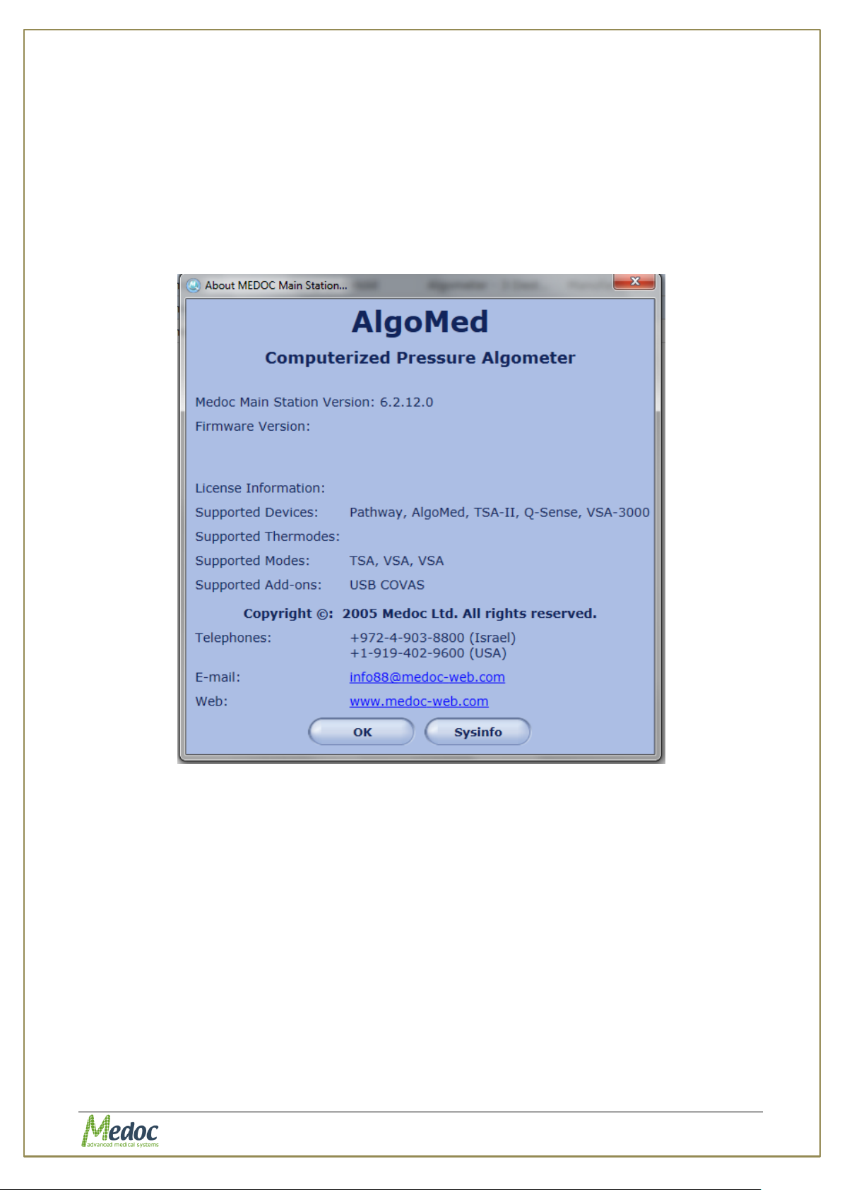
AlgoMed Technical Reference Manual
11. System Information
To view system information regarding system, software and license select About MEDOC
Main Station from the Help menu in the top menu bar. The information displayed includes:
Software version.
Firmware (PATHWAY) version – Not relevant for AlgoMed users.
Firmware serial number – For AlgoMed users this refers to the license number.
Supported Thermodes (according to license – Not relevant for AlgoMed only
users).
MEDOC contact information.
Figure 64: System Information
In order to send full system information to Medoc:
1. Click the Sysinfo button. A system information file similar to the following, is created and
displayed:
Proprietary 96 of 110
Page 97
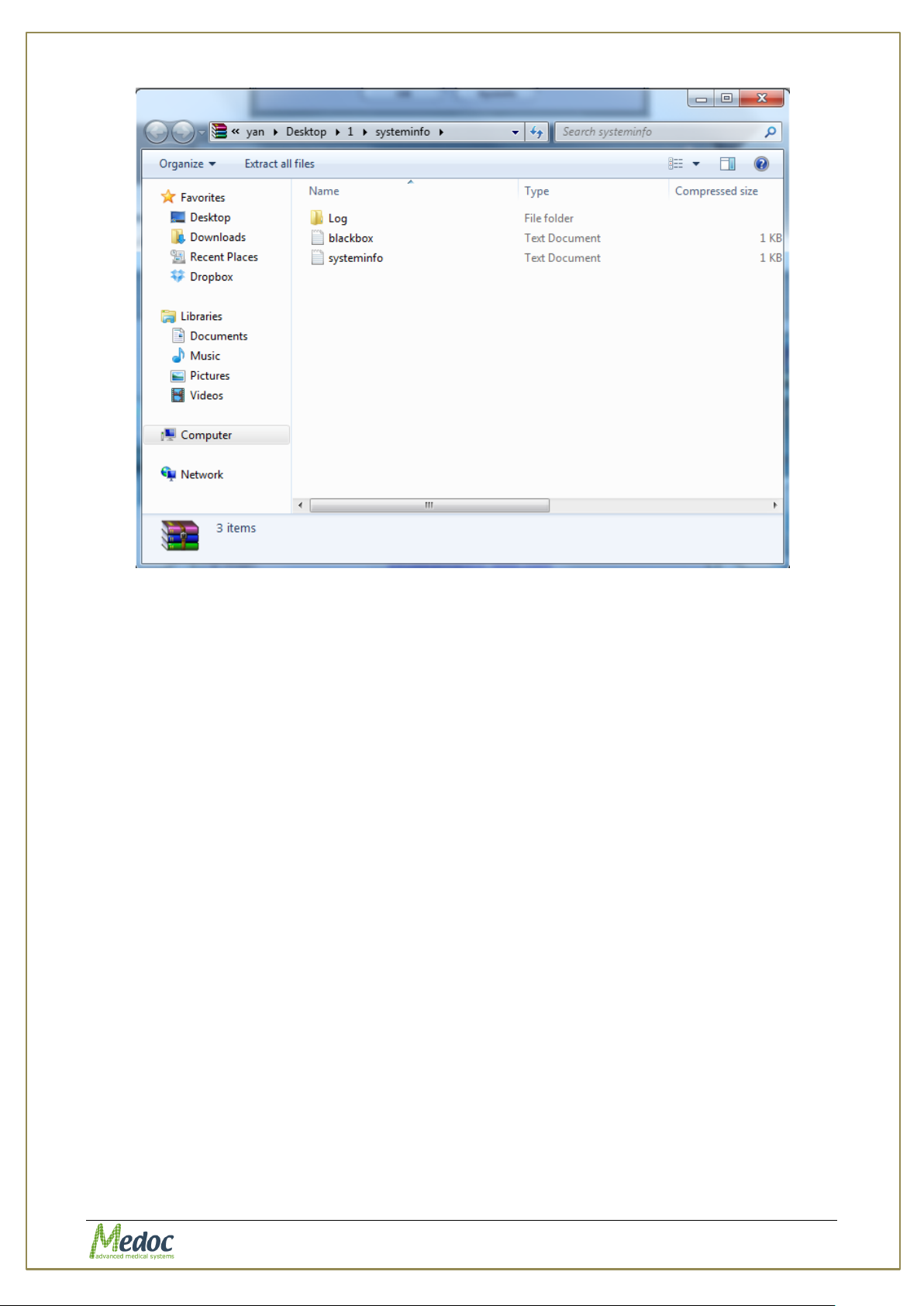
AlgoMed Technical Reference Manual
Figure 65: Sysinfo File Sample
2. Save the file and send it by mail to your Medoc Service contact.
Proprietary 97 of 110
Page 98
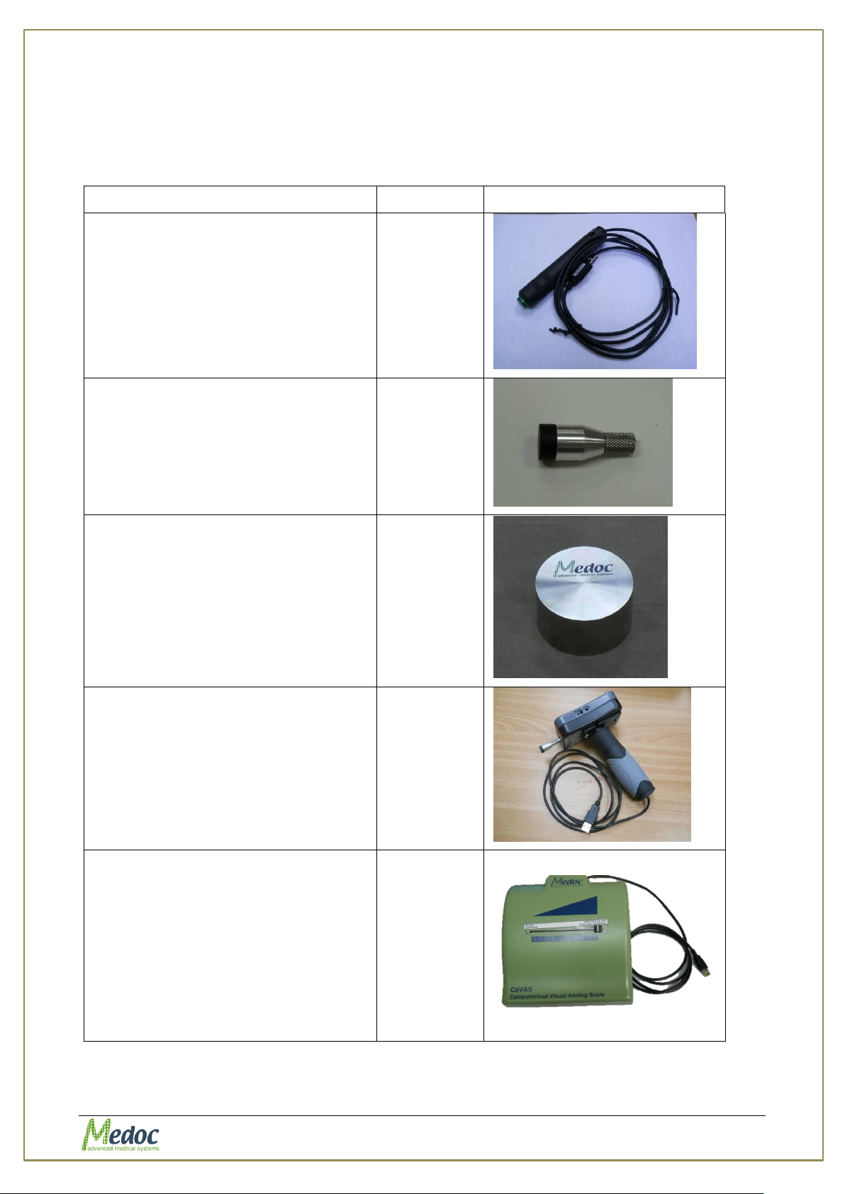
AlgoMed Technical Reference Manual
Description
Cat. No.
USB Patient Response Unit (PRU)
DT 00012
1 cm2 Rubber Tip
DT 00010-3
Calibration Verification Weight
MP 00351
Algometer Handle
MP 00350
USB CoVAS – Computerized Visual
Analog Scale
While the Q-sense delivers a heat
stimulus to a tested subject’s body
site, the subject simultaneously
moves the CoVAS slide. The
movement of the slide is between a
predefined minimum and maximum (0
to 100), which depicts the level of
pain he/she feels.
AS 00213
12. Appendix A – Accessories
The following list of accessories can be purchased from Medoc, and are listed with their
Catalogue numbers, which should be quoted when ordering a specific accessory.
Table 24: Accessories
Proprietary 98 of 110
Page 99
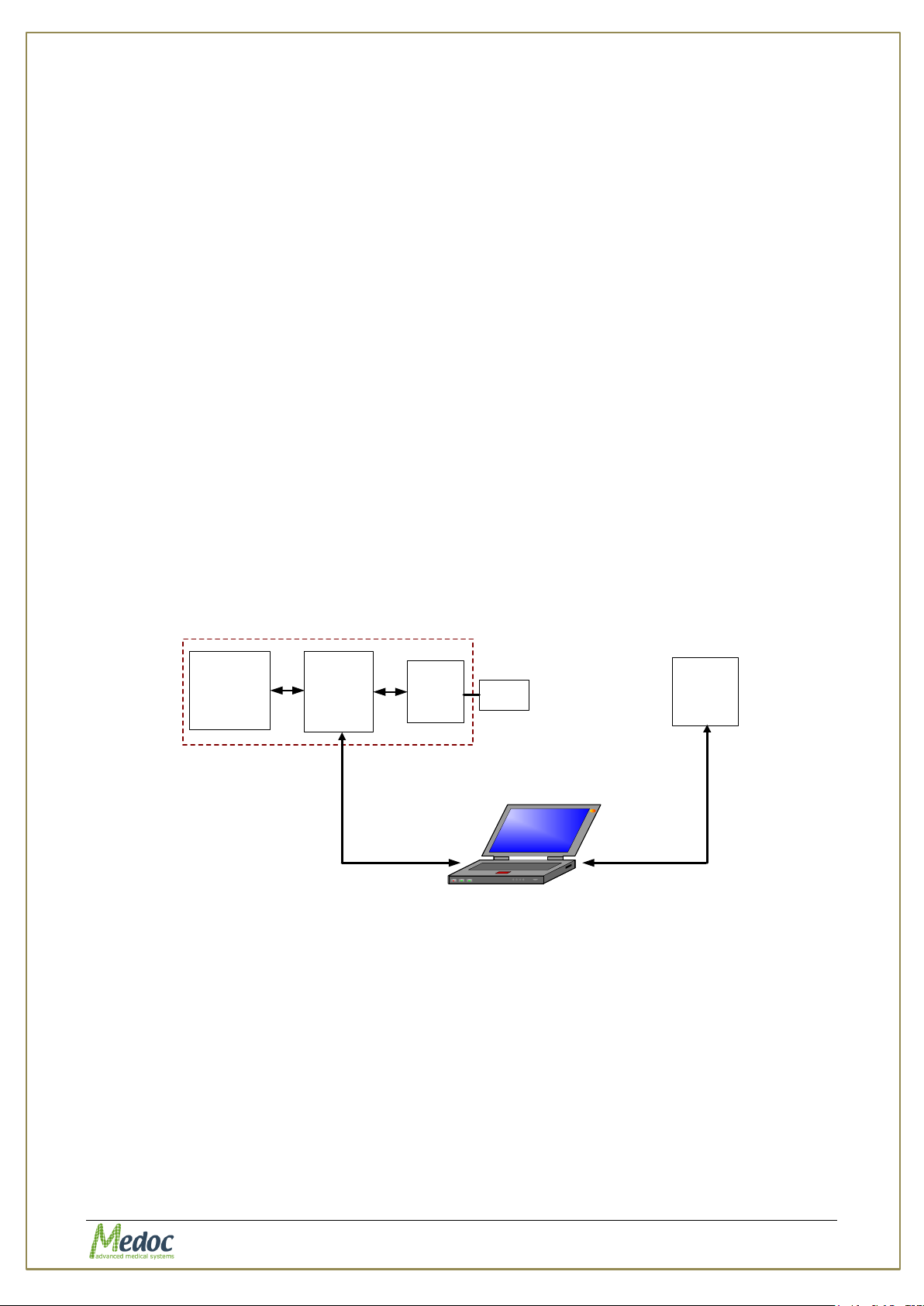
AlgoMed Technical Reference Manual
RS232 - USB
Rechargeable
Battery
Algometer box
Electronics Load Cell
Monitoring System
USB
Response
Unit
RS232 - USB
Rubber
Tip
13. Appendix B – System and Module Description
13.1 System Description
The Algometer design makes it easy to troubleshoot and replace parts.
The system consists of several main modules:
FPIX Algometer
Electronic circuits
Load cell
Algometer Accessories
Rubber tip 1cm
USB Response Unit.
Calibration verification weight
Ergonomic grip handle
Algometer Utilities
Laptop.
2
Printer.
Figure 66: System Diagram
Proprietary 99 of 110
Page 100
AlgoMed Technical Reference Manual
Do not perform calibration or maintenance to the AlgoMed
while in use.
If the Algometer is not planned to be used in the coming weeks, store it in
its original package supplied by Medoc.
In order to verify the Algometer calibration, use the Calibration
verification weight (supplied by Medoc).
14. Appendix C – Preventive and Periodical
Maintenance
This chapter describes periodic maintenance procedures.
14.1 Periodical Visual Check
A periodical visual check is necessary for the Algometer system performance. The visual check
keeps Algometer and its accessories in operational condition at all times.
1. Check Algometer and all accessories visually
1.1. Check that there is no visible damage to the Algometer
1.2. Check that the communication cable is intact
1.3. Check that accessories connector is intact
1.4. Check that accessories body is intact
2. Assemble Algometer and connect it to the PC
3. Run a few test protocols, using the AlgoMed software, to verify Algometer runs without
problems
14.2 Calibration Verification
It is recommended to periodically verify the Algometer calibration is within acceptable
tolerance.
Follow the steps below in order to perform Calibration Verification:
1. Make sure AlgoMed is turned OFF.
2. Position the AlgoMed with its tip pointing upright as displayed in the image below
3. Turn the AlgoMed ON, and wait until it finishes initialization
4. Set AlgoMed units to Kgf by using the UNITS button
Proprietary 100 of 110
 Loading...