

Page 1
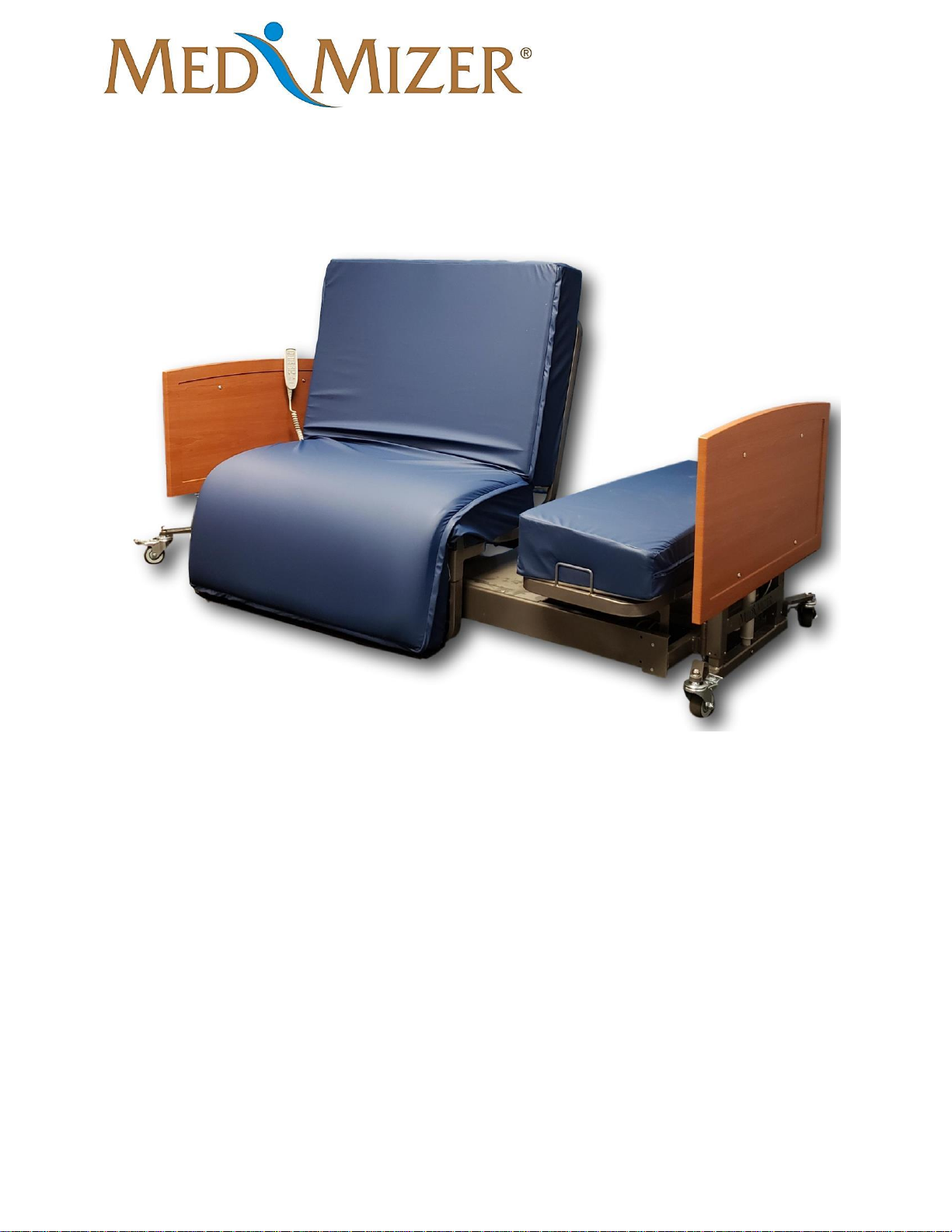
ActiveCare - Standard
User Manual
MAN-ActiveCare REV03 ActiveCare Standard USER MANUAL Page 1 of 33
ActiveCare-Standard
USER MANUAL
For Parts or Technical Assistance - (877) 867-7365
Page 2

ActiveCare - Standard
User Manual
MAN-ActiveCare REV03 ActiveCare Standard USER MANUAL Page 2 of 33
TABLE OF CONTENTS
Overview
Introduction
3
Intended Use
3
Safety Information
3
Specifications
6
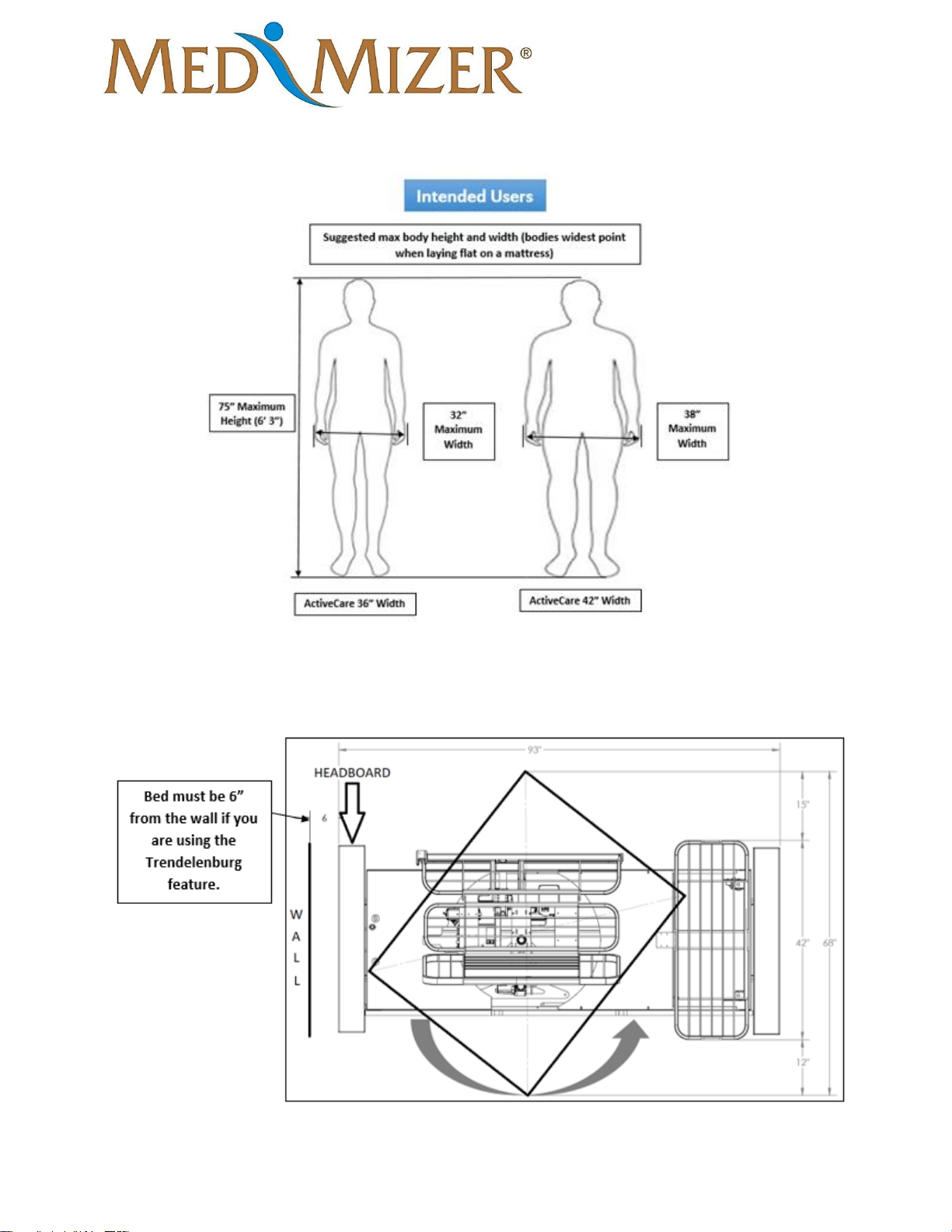
Intended Users
7
Bed Placement Dimension
7
Options and Accessories
8 Preparation for Use
Unpacking
9
Assembly
13
Pivot Alignment
18
Mattress Installation
20
Pivot Turn – Opposite Direction
22
Switching Hand Pendant to Opposite Side
24
Operation
Control Options
29
Bed Transport
30
Maintenance
Cleaning
30
Maintenance and Service
30
Service Part List
31
Warranty
33
Page 3

ActiveCare - Standard
User Manual
MAN-ActiveCare REV03 ActiveCare Standard USER MANUAL Page 3 of 33
Overview
Introduction
This manual provides instructions for use of the ActiveCare Bed. Do not operate the bed without
first reading and understanding the warnings and cautions provided herein.
NOTICE: The information in this document is subject to change without notice.
Intended Use
The ActiveCare Bed is intended to provide means for a single occupant to recline and sit, and to
assist the occupant in moving between reclining, sitting and standing positions.
The bed is intended for use in long and short-term care facilities, and homes.
The bed is intended to support a safe working load of 600 lbs. (evenly distributed), which
includes the weight of the occupant, mattress, bedding, and any other items on the bed deck.
The bed is intended for operation by adult users who have read and understand this User Manual.
The bed is intended for indoor use in environments where it will not get wet, where floors are
stable and level, and in ambient temperatures between 41°F and 104°F.
The bed is intended for operation on 120 VAC, 60 Hz mains power.
The bed is not intended to provide a means for transport of the occupant.
Safety Information
This symbol identifies a WARNING or CAUTION: IF SYMBOL IS ON BED
CONSULT USER MANUAL FOR EXPLANATION
WARNING represents potentially dangerous situations that can lead to serious physical
injury or death.
CAUTION represents potentially dangerous situations that can lead to minor physical
injury.
General Use Safety
WARNING Bed must be used as specified under the “Intended Use” heading. Use of the
bed outside of the specified conditions may result in personal injury or equipment
damage.
Page 4

ActiveCare - Standard
User Manual
MAN-ActiveCare REV03 ActiveCare Standard USER MANUAL Page 4 of 33
WARNING Close supervision by an adult who has read and understands this User
Manual is required when the bed is used around children or others who have not or
cannot read and/or understand this User Manual.
WARNING The bed mattress must be purchased from Med-Mizer Inc. to meet
entrapment zone dimensional guidelines published by the Food and Drug Administration.
WARNING Do not spill or spray liquid on the bed. Excessive liquid on the bed can
result in an electric shock hazard. In the event of a liquid spill or excessive liquid on the
bed, unplug the bed immediately. Remove excess liquid and allow bed to dry thoroughly
before restoring power.
WARNING Never permit anyone under the bed while the bed is being used. Failure to do
so could result in personal injury.
WARNING Never operate the bed if a cord or plug is damaged, or it is not working
properly. Contact Qualified Service Personnel for inspection and/or repair. Failure to do so
could result in personal injury.
WARNING DO NOT sit or lie on hand control. It can cause unintended movement of the
application.
WARNING Ensure the main power cord is routed where it is not pinched either under or
beside the bed. Failure to do so could result in personal injury or equipment damage.
CAUTION Ensure the grounding cable of the control box is securely fastened to the frame.
Failure to do so could result in personal injury or equipment damage.
CAUTION If a handset is used, the cord must be routed and secured properly to ensure
that cord does not become entangled. Failure to do so could result in equipment damage or
personal injury.
CAUTION Keep all moving parts free of obstruction (i.e. blankets, sheets, pads, tubing,
etc.)
CAUTION Never remove any labels applied to the bed. Failure to do so could result in
personal injury or equipment damage.
CAUTION Do not exceed the maximum allowable weight capacity on this bed. The
maximum weight is the sum of the resident/patient, mattress, bedding material, and
accessories.
Page 5

ActiveCare - Standard
User Manual
MAN-ActiveCare REV03 ActiveCare Standard USER MANUAL Page 5 of 33
CAUTION Keep the bed in low position when the occupant is unattended. High bed
positions increase the risk of injury from falling when getting in or out of bed, or while
reclined.
CAUTION To avoid a fire hazard; do not use the bed in an oxygen-enriched
environment or in the presence of explosive gases.
CAUTION To avoid an electric shock hazard; do not plug the power cord into a wall
outlet if the power cord is damaged, if the ground pin is missing, or if the wall outlet does
not provide for the power cord ground pin.
Bed Articulation Safety
WARNING Always confirm the area under the bed and end-boards are free and clear of
children, inattentive adults, pets, and objects when raising and lowering or pivoting the
bed.
WARNING Do not place body parts or objects under bed or moving part mechanisms.
Failure to do so could cause serious injury or equipment damage.
WARNING Electric drive bed mechanisms can cause serious injury if operated
improperly. Operate the bed only when persons are clear of the mechanisms.
CAUTION When lowering the bed or knee in chair position, always ensure limbs or
extremities are not under any portion of the bed or mattress.
CAUTION Always confirm limbs or extremities are within the perimeter of the mattress
and not in a position where they can be trapped or pinched by the support arms and assist
bars when adjusting head and knee elevation.
CAUTION Keep moving parts of bed free of obstructions, including bedding, heating
pads, tubes, cords and wires. Items caught in moving parts may be crushed, cut or pulled
during bed adjustment.
Side Rail and Assist Bar Safety
WARNING Always confirm the side rail and assist bars are locked in the raised position.
Improperly locked support arms and assist bars can result in a fall hazard due to sudden
unexpected movement.
Options and Accessories Safety
CAUTION Use only bed accessories and bed replacement parts supplied or approved by
Med-Mizer® for this bed. Third party accessories and replacement parts that are not
approved by Med-Mizer® may result in personal injury or equipment damage.
Page 6

ActiveCare - Standard
User Manual
MAN-ActiveCare REV03 ActiveCare Standard USER MANUAL Page 6 of 33
Cleaning Safety
WARNING Do not spill or spray liquid on the bed. Excessive liquid on the bed can
result in an electric shock hazard. In the event of a liquid spill or excessive liquid on the
bed, unplug the bed immediately. Remove excess liquid and allow bed to dry thoroughly
before restoring power.
CAUTION Follow manufacturer’s instructions for proper use of cleaning agent.
Improperly diluted or improperly applied cleaning agents can result in inadequate
disinfection or a caustic burn hazard.
CAUTION Clean the hand control regularly to ensure good hygiene standards.
Maintenance and Service Safety
WARNING Before performing bed maintenance or service, unplug the power cord to
avoid an electric shock hazard.
WARNING If a fault or problem is found during preventative maintenance inspections,
remove the bed from service until the appropriate repair or adjustment is made.
Specifications
“Low” Deck Height Range
13.5”
Maximum Head Angle
58º ± 3º
“High” Deck Height Range
27.5”
Maximum Head Angle(pivoted)
90º ± 3º
Safe Working Load
600 lbs.
Maximum Knee Angle
29º ± 3º
Overall Bed Widths
36", 42"
Power Requirements
120 VAC, 50 Hz
Overall Bed Length
94.00"
Maximum Current Draw
4.5 amps
Overall Bed Weight
(36”) 365lbs,
(42”) 375lbs
Controller Output Voltage
24 VDC
Weight with Standard
Boards
(36”), 395lbs
(42”), 405lbs
Page 7
ActiveCare - Standard
User Manual
MAN-ActiveCare REV03 ActiveCare Standard USER MANUAL Page 7 of 33
Intended Users
Bed Placement Dimensions
Page 8

ActiveCare - Standard
User Manual
MAN-ActiveCare REV03 ActiveCare Standard USER MANUAL Page 8 of 33
Options and Accessories
• UD Rails (1/4 rails for head)
• Pivoting Assist Bars (not available on same side of bed as Mobility Bar)
• Mobility Bar
• Trapeze
• Battery Backup
• Trend/Reverse Trend Handset
End Boards
Headboard and Footboard Finish Options
Custom Headboard and Footboards Available
Page 9
ActiveCare - Standard
User Manual
MAN-ActiveCare REV03 ActiveCare Standard USER MANUAL Page 9 of 33
Unpacking (If Shipped LTL/Commercial)
Tools Required:
• Utility knife/side cutting shears
• ½” Socket with rachet/impact driver
• 9/16” Wrench
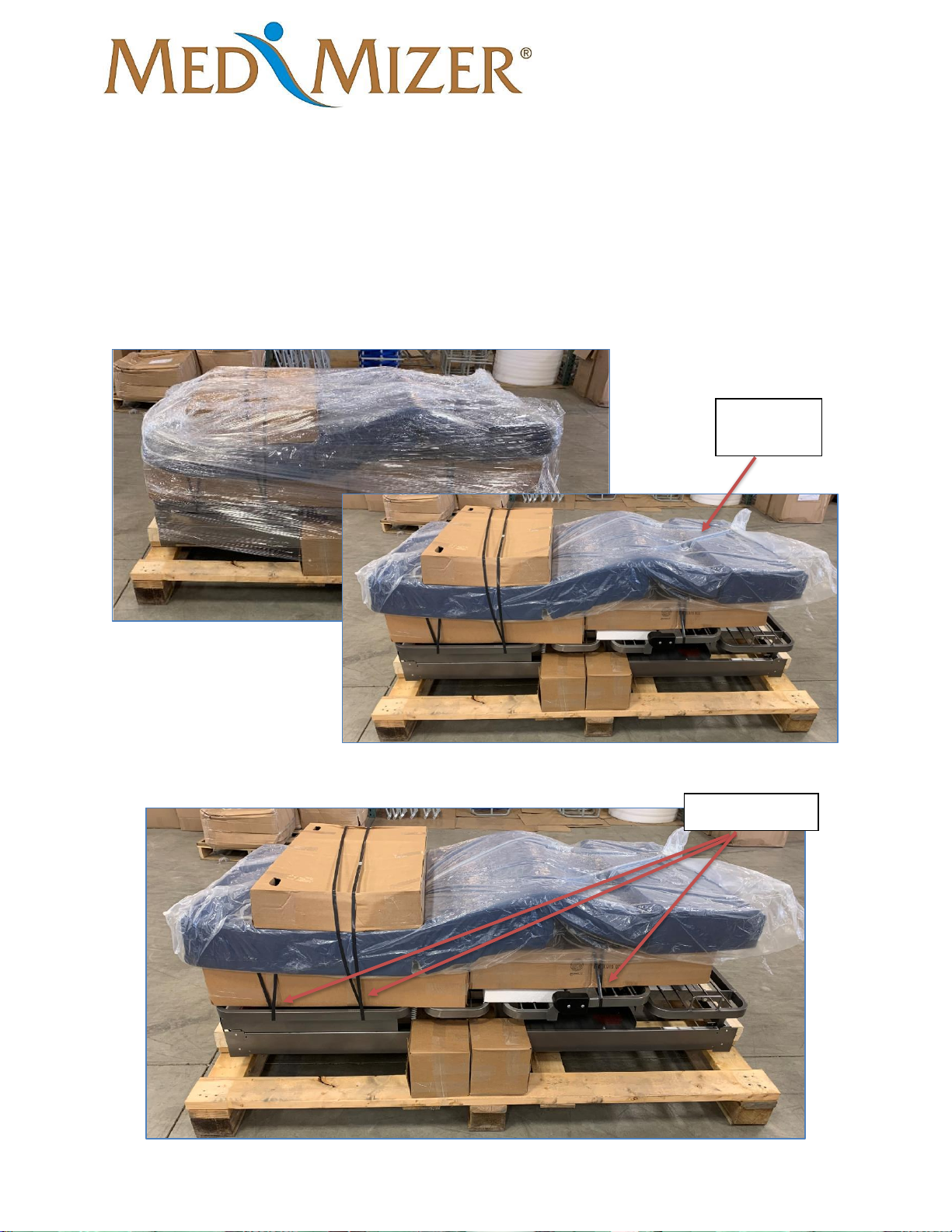
1. Carefully remove outside box and shrink wrap with utility knife. (Do not puncture boxes
or mattress)
2. Cut the three straps holding the boxes and
Bed
unwrapped
Cut the straps
Page 10
ActiveCare - Standard
User Manual
MAN-ActiveCare REV03 ActiveCare Standard USER MANUAL Page 10 of 33
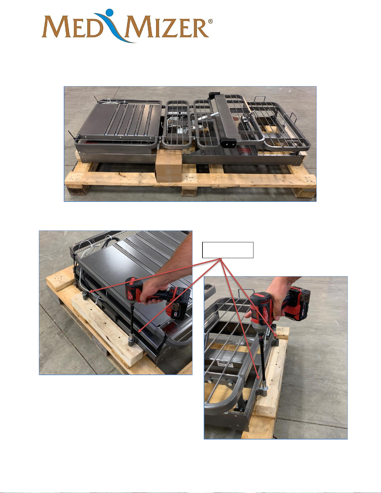
3. Remove boxes and mattress and put them off to the side.
4. Unbolt the four anchor bolts on each end of the bed.
Anchor bolts
Page 11
ActiveCare - Standard
User Manual
MAN-ActiveCare REV03 ActiveCare Standard USER MANUAL Page 11 of 33
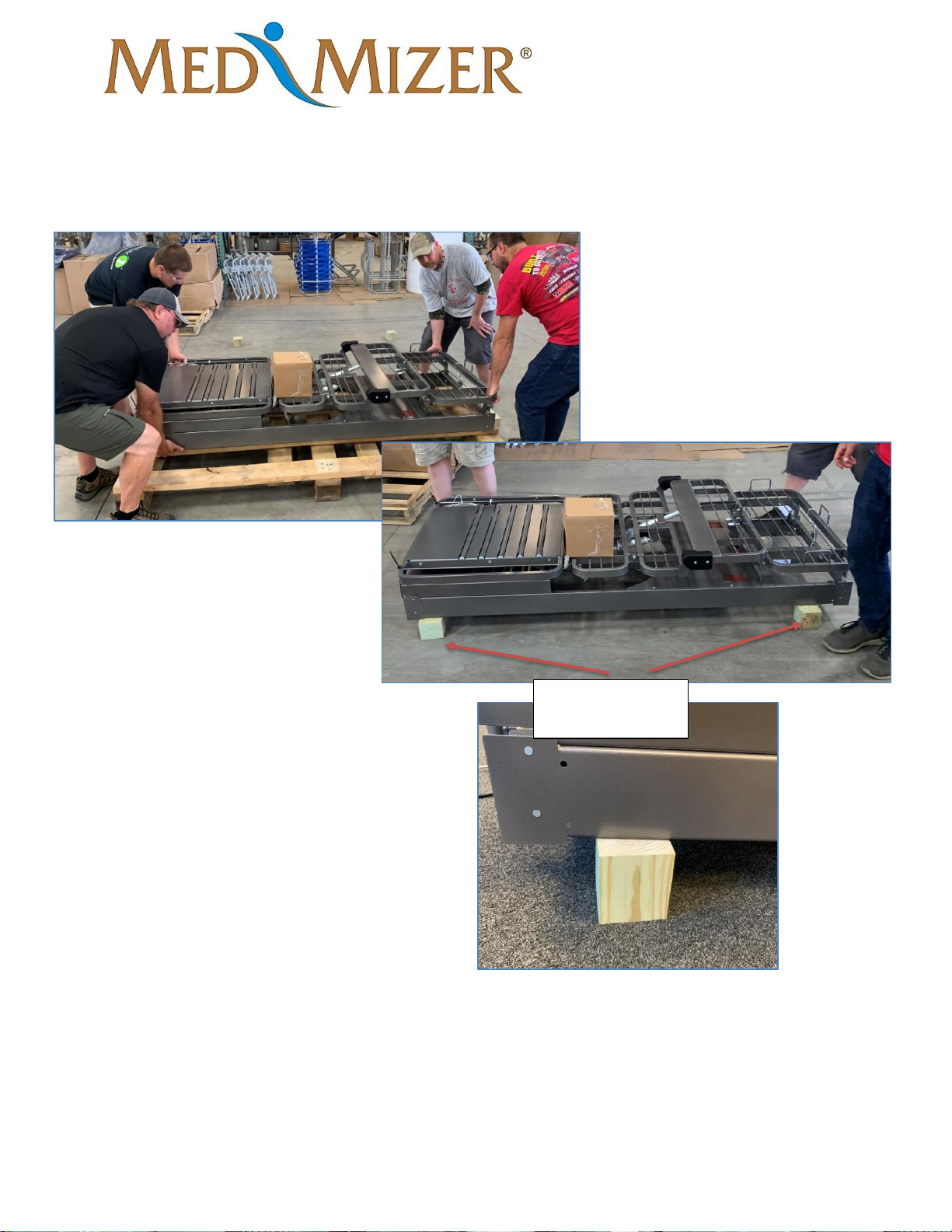
5. Lift bed off pallet and put on installation blocks (installation blocks included with bed, in
small box).
Frame resting on
assembly blocks
Page 12
ActiveCare - Standard
User Manual
MAN-ActiveCare REV03 ActiveCare Standard USER MANUAL Page 12 of 33
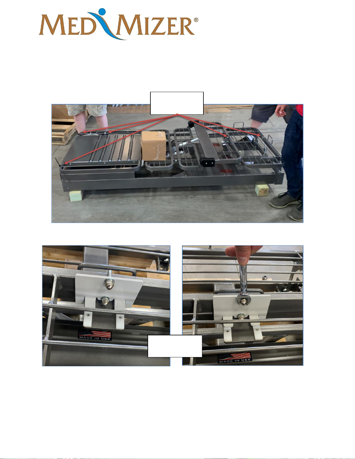
6. Remove cable ties from frame.
7. Remove white shipping bracket from frame. (use 9/16” wrench)
8. Remove Pendant from box
Cable tie
locations
White shipping
bracket
Page 13
ActiveCare - Standard
User Manual
MAN-ActiveCare REV03 ActiveCare Standard USER MANUAL Page 13 of 33
Assembly
Tools Required:
• 5/8 Wrench
• 5/8 Socket
• 6” Socket Extension
• Ratchet/Impact Driver
• Side Cutters
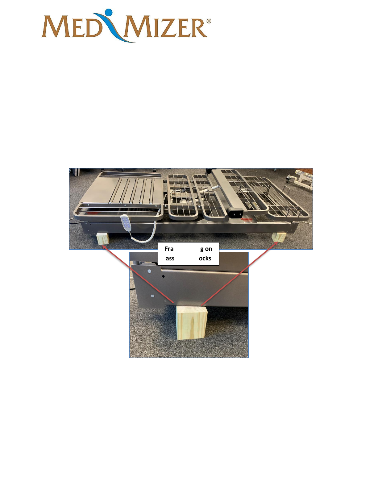
1. Begin with bed frame resting on installation block. (as seen in unpacking instructions)
Frame resting on
assembly blocks
Page 14
ActiveCare - Standard
User Manual
MAN-ActiveCare REV03 ActiveCare Standard USER MANUAL Page 14 of 33
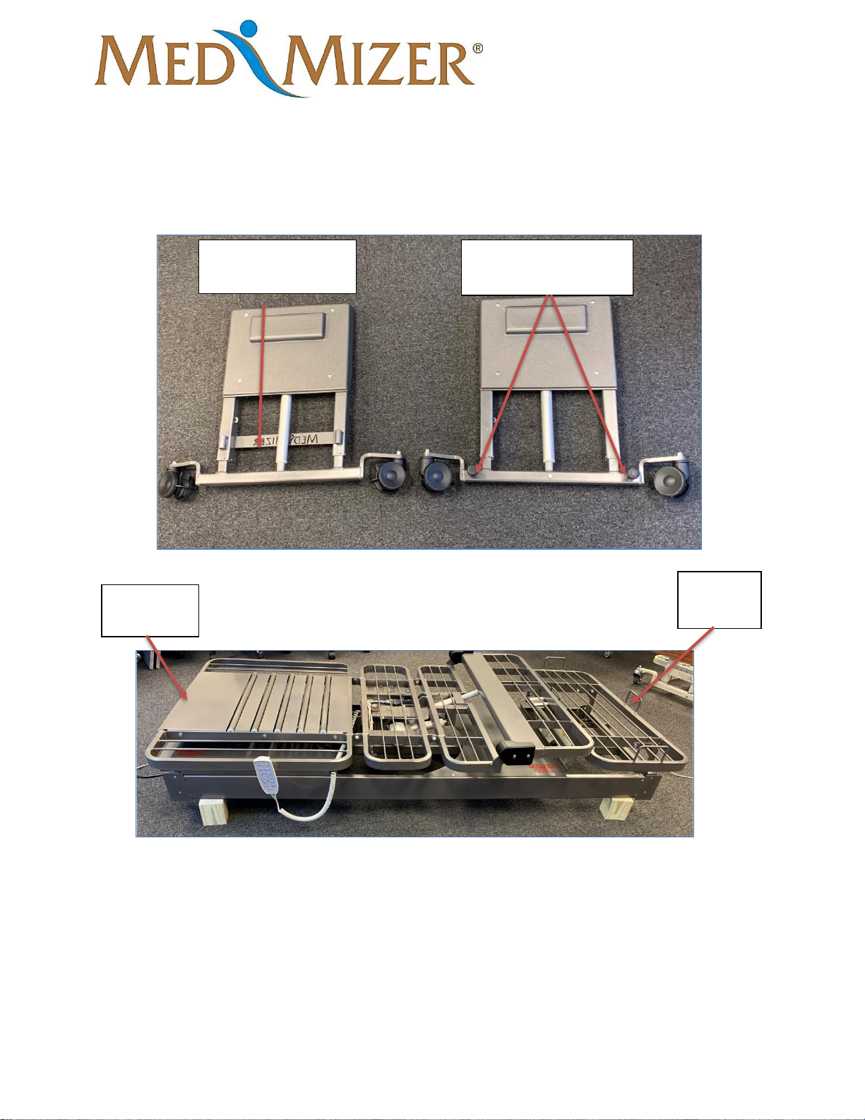
2. Determined which high/low assembly goes to the head and foot of the bed. The foot
weldment has the Med-Mizer logo welded on the bottom, and the head weldment has
wall bumpers at the bottom of the weldment.
Foot Weldment with
Med-Mizer strap
Head Weldment with
rubber wall bumpers
Head End
of Bed
Foot End
of Bed
Page 15
ActiveCare - Standard
User Manual
MAN-ActiveCare REV03 ActiveCare Standard USER MANUAL Page 15 of 33
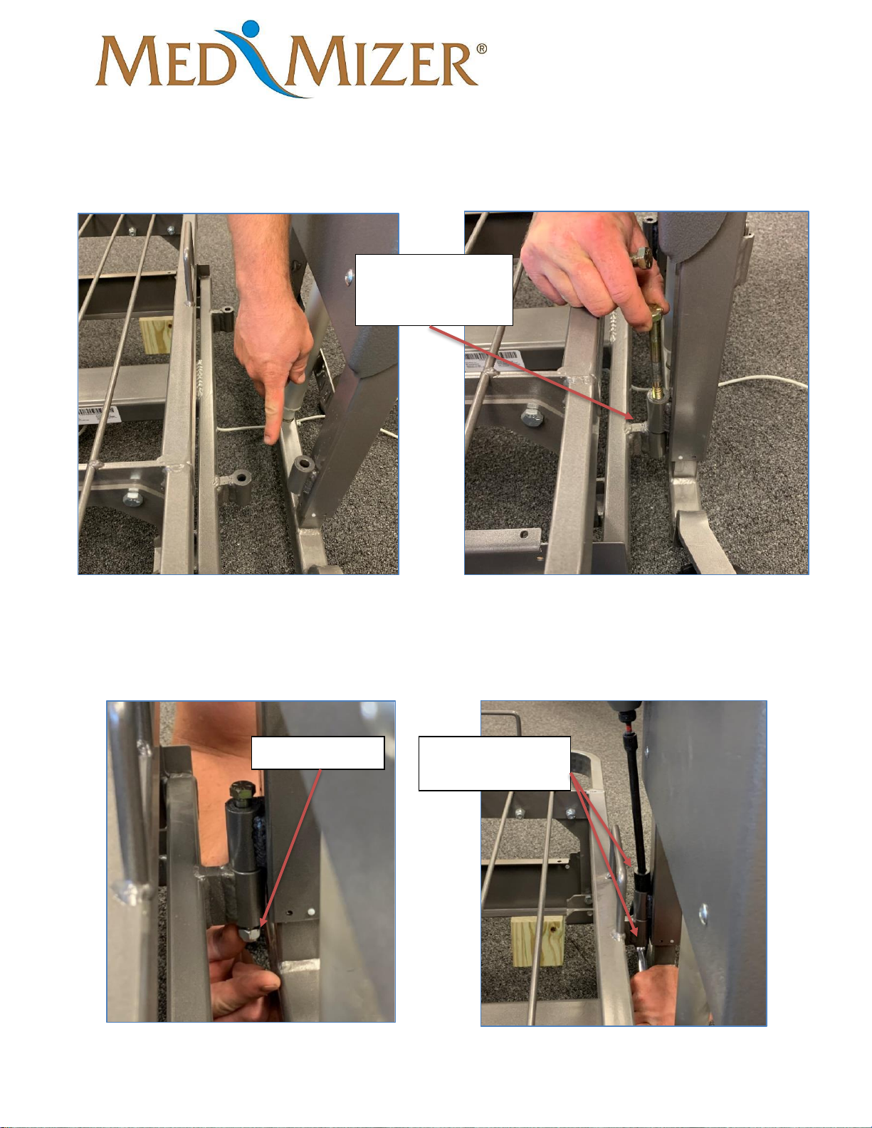
3. Install high/low weldments to the frame using the bolts and nuts provided. The high/low
assembly bosses must go on top of the frame bosses.
4. Hand tighten nuts to each bolt and fasten firmly using the 5/8” ratchet/impact and 5/8”
wrench.
High/Low weldment
mounted on top of
frame boss.
Hand tighten nut
Firmly fasten nuts
and bolts together
Page 16
ActiveCare - Standard
User Manual
MAN-ActiveCare REV03 ActiveCare Standard USER MANUAL Page 16 of 33
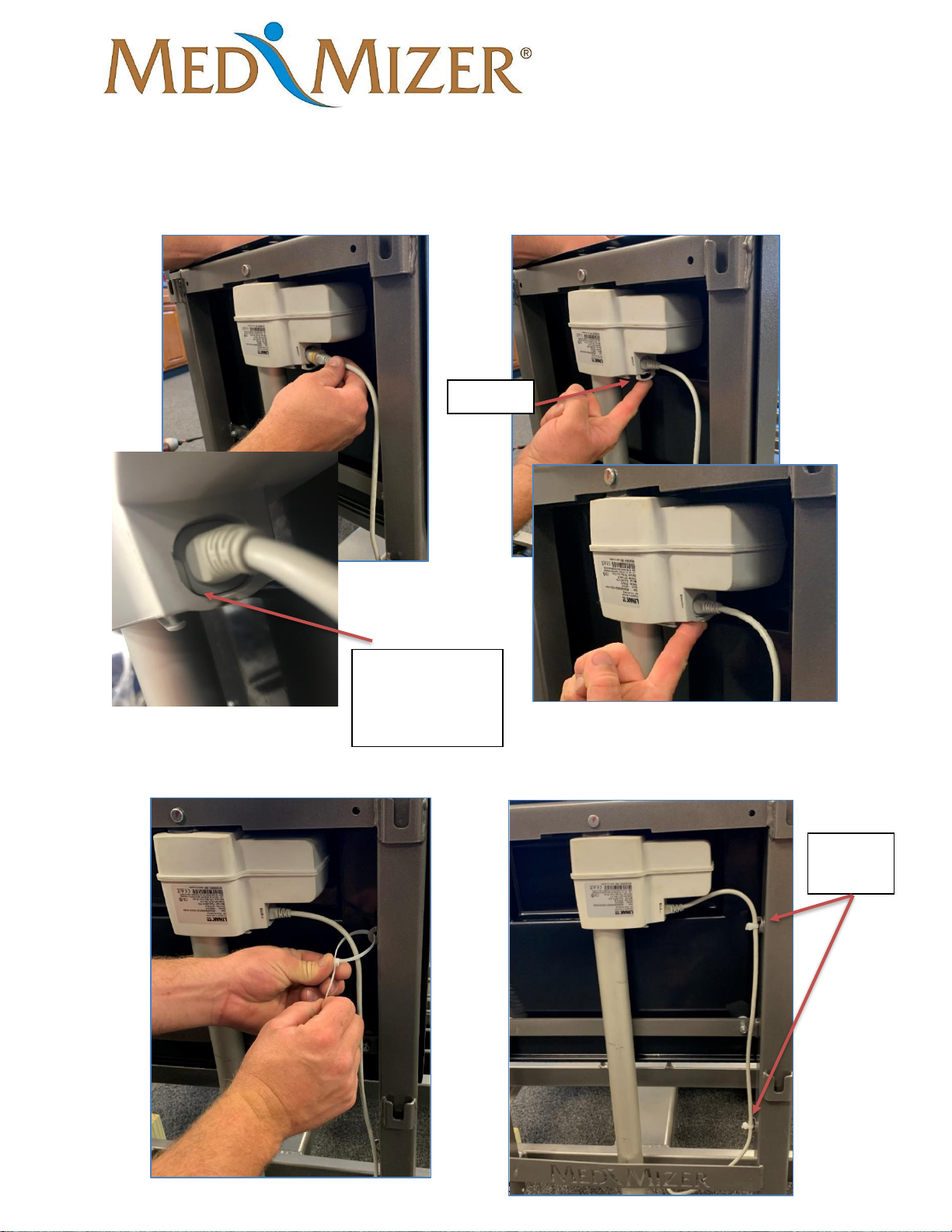
5. Install motor extension cable into actuator. Ensure cable is full inserted then install c-
clip.
6. Zip tie cable to the two attachment points and cut excess.
Two zip
ties
C-Clip
Cable should look
like this once clip
is installed
Page 17
ActiveCare - Standard
User Manual
MAN-ActiveCare REV03 ActiveCare Standard USER MANUAL Page 17 of 33
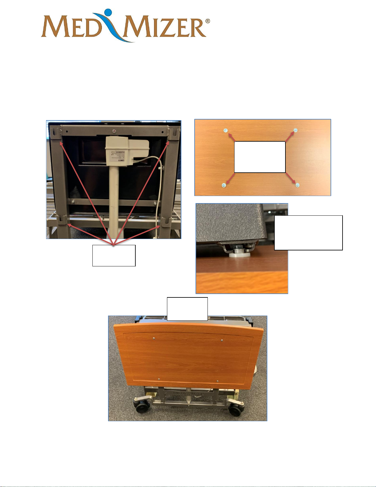
7. Install head/foot board to the weldment. Slide board mount brackets down into channel
brackets.
Board
mounting
brackets
Channel
Brackets
Installed
Board
To secure in place
push down on board
until it stops
Page 18
ActiveCare - Standard
User Manual
MAN-ActiveCare REV03 ActiveCare Standard USER MANUAL Page 18 of 33
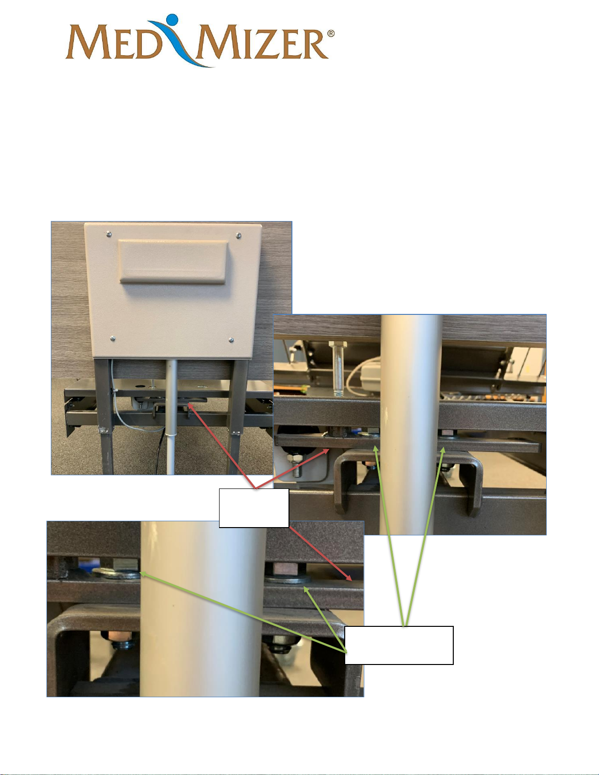
8. Repeat steps 3 through 7 to install opposite end high/low weldment.
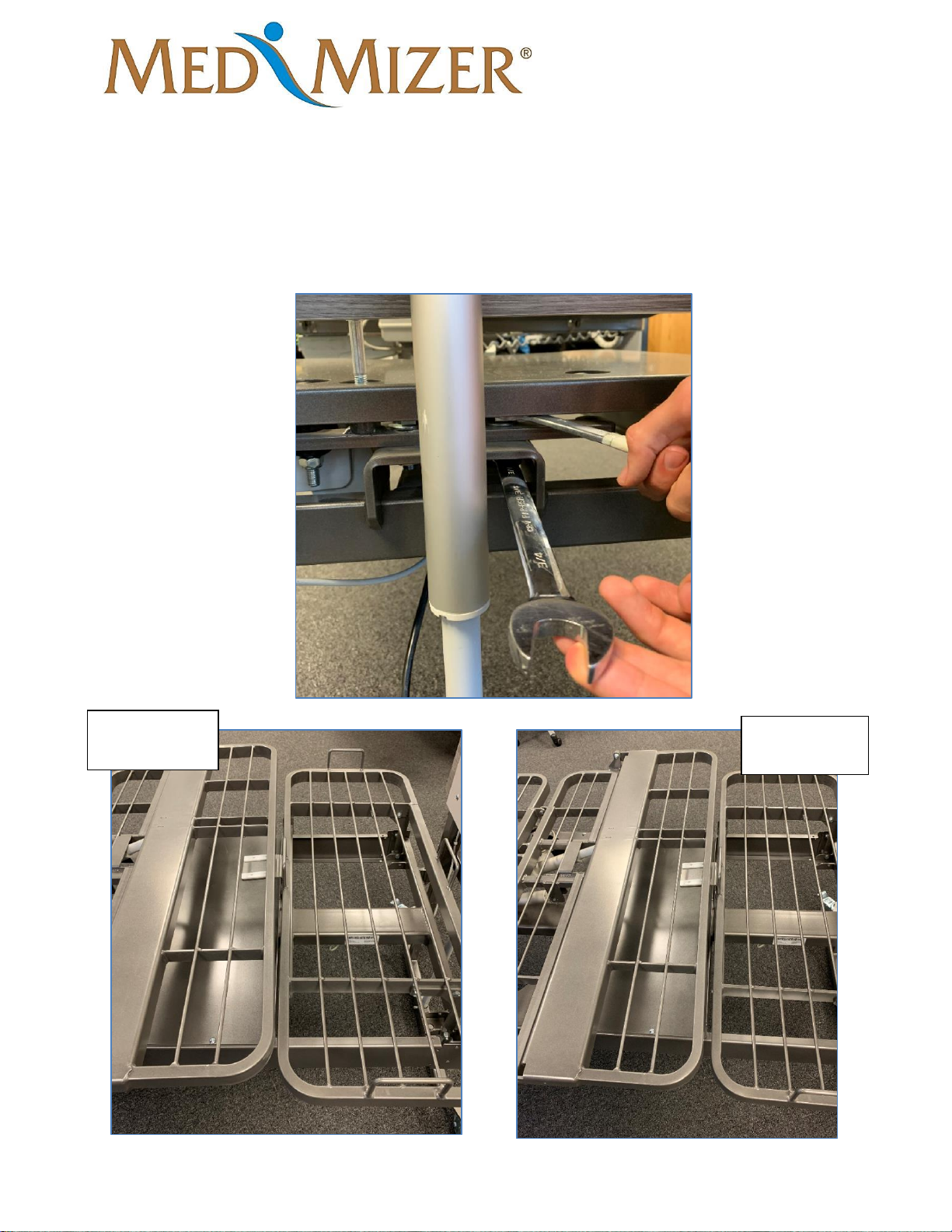
Pivot Alignment (If Needed)
Tools Required:
• (2) ¾” wrenches
1. Go behind the headboard of the bed and find the adjustment bracket and the two bolts.
Adjustment
bracket
Bolts holding
adjustment bracket
Page 19
ActiveCare - Standard
User Manual
MAN-ActiveCare REV03 ActiveCare Standard USER MANUAL Page 19 of 33
2. Using the two ¾” wrench loosen each bolt ¼ turn, do not fully disassemble. Once loose,
straighten the bed out. View images below to see incorrect alignment and correct
alignment. The pivoting and fixed sections of the bed should be parallel. Once straight
retighten the bolts.
Incorrect
Alignment
Correct
Alignment
Page 20
ActiveCare - Standard
User Manual
MAN-ActiveCare REV03 ActiveCare Standard USER MANUAL Page 20 of 33
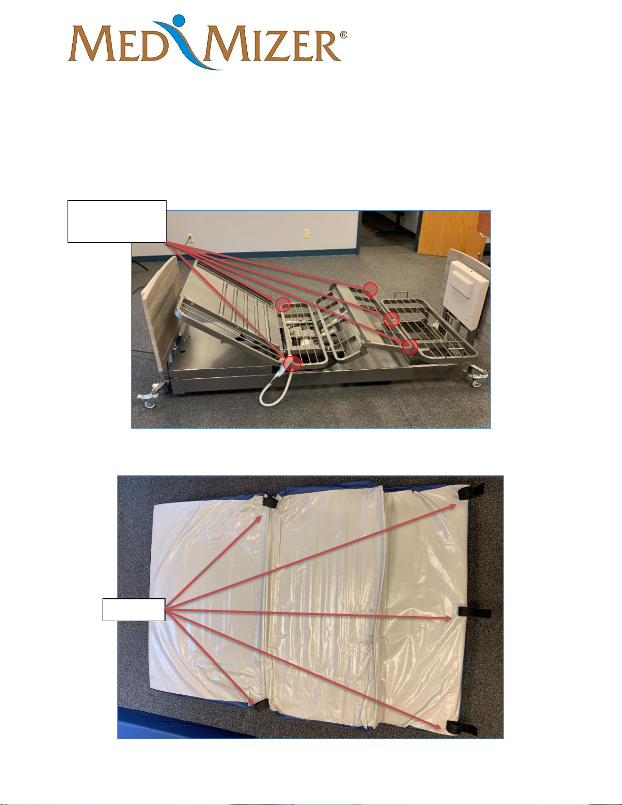
Mattress Installation
1. Using the auto-contour button raise the head and leg section of the bed.
2. Locate the straps on the back of the mattress.
Straps
Strap attachment
points
Page 21
ActiveCare - Standard
User Manual
MAN-ActiveCare REV03 ActiveCare Standard USER MANUAL Page 21 of 33
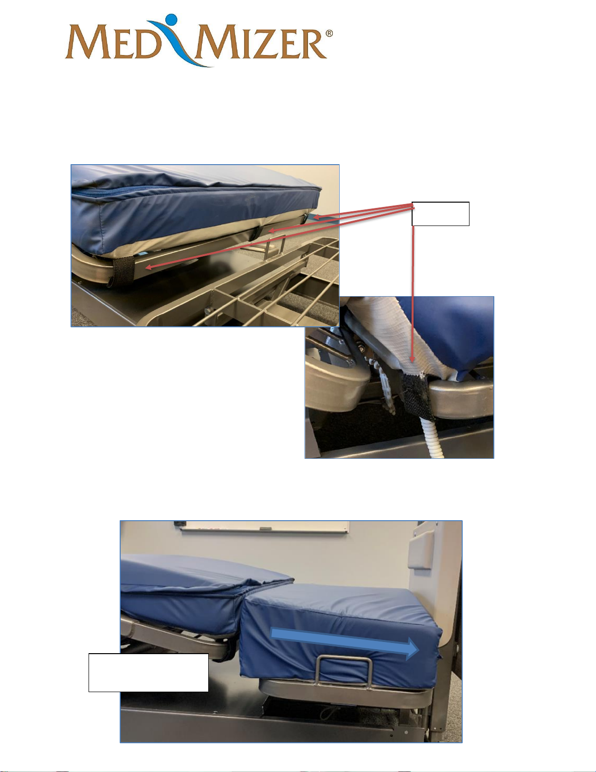
3. Place mattress on bed and Velcro the straps to the sleep surface.
4. Install foot portion of the mattress with the slope going towards the foot board.
Straps
Slope going towards
the footboard
Page 22
ActiveCare - Standard
User Manual
MAN-ActiveCare REV03 ActiveCare Standard USER MANUAL Page 22 of 33
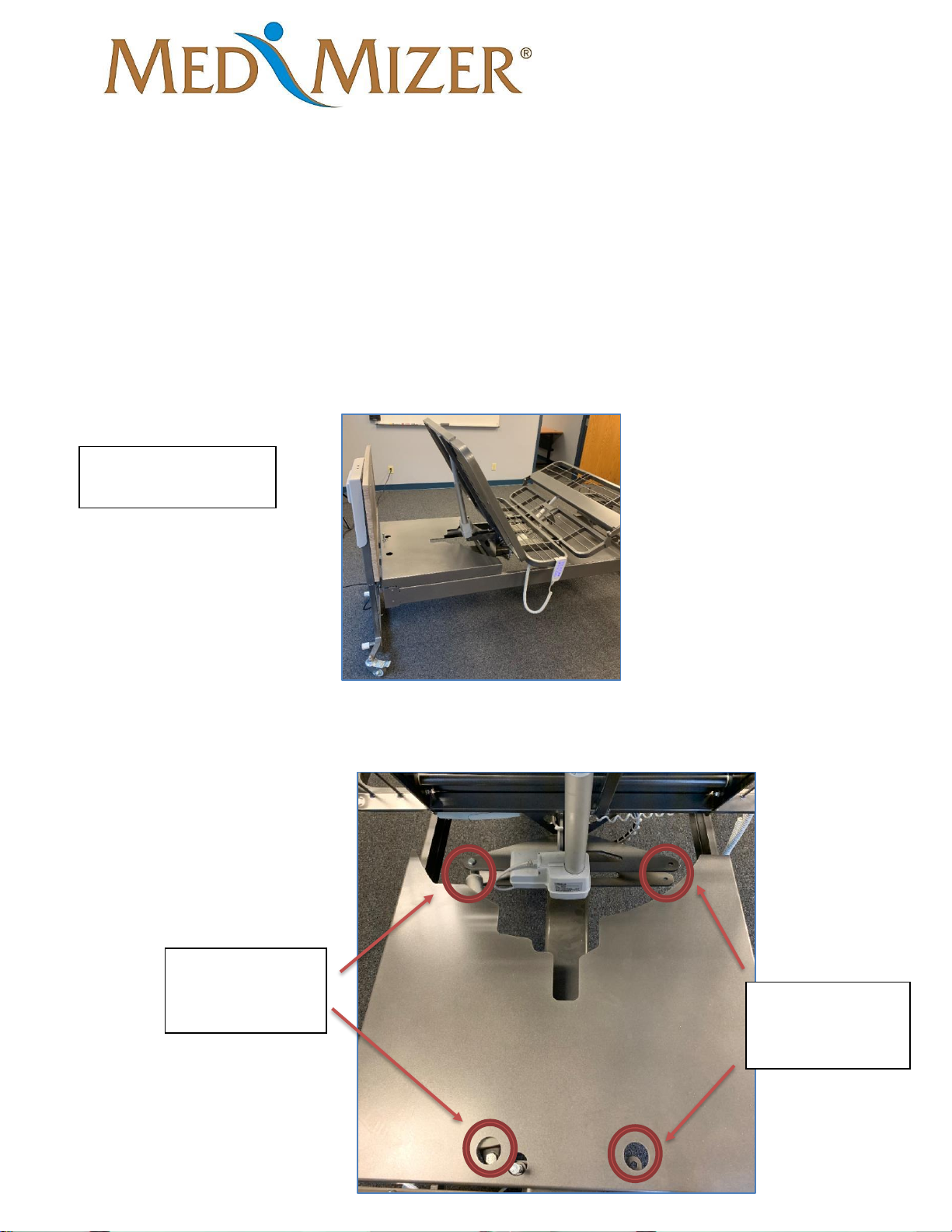
Pivot Bed Turn Left (factory installed to turn right)
Tools required
• 17mm wrench
• 17mm socket
• Drill/Impact
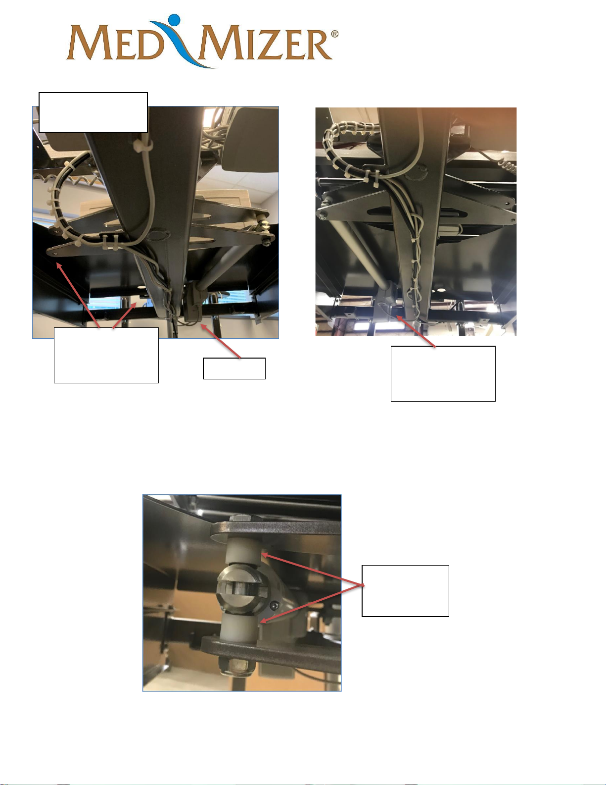
1. In the bed position, raise the height of the bed and head of the bed to its highest point.
2. Locate and remove the two bolts pictured below that hold the actuator into place. Once
removed, install the actuator to the corresponding holes on the opposite side of the bed.
Bed and head section
raised all the way up
Remove bolts
using 17mm
wrench and socket
Corresponding
locations to install
actuator
Page 23
ActiveCare - Standard
User Manual
MAN-ActiveCare REV03 ActiveCare Standard USER MANUAL Page 23 of 33
3. Install spacers and fasteners back in actuator mounts. Tighten the fastener so that
the bolt comes through the nylon nut but do not overtighten or the actuator will bind
causing damage. Actuator should pivot freely.
Image from
underneath the bed
Actuator
Corresponding
locations to install
actuator
Actuator mounted
in “Left turn
Position”
Reinstall
spacers as seen
in the picture
Page 24
ActiveCare - Standard
User Manual
MAN-ActiveCare REV03 ActiveCare Standard USER MANUAL Page 24 of 33
Swapping Hand Pendant (factory installed to the Left side of bed)
Beds without Trendelenburg handset
Tools Required
• 5/16” Socket
• Impact driver/ratchet
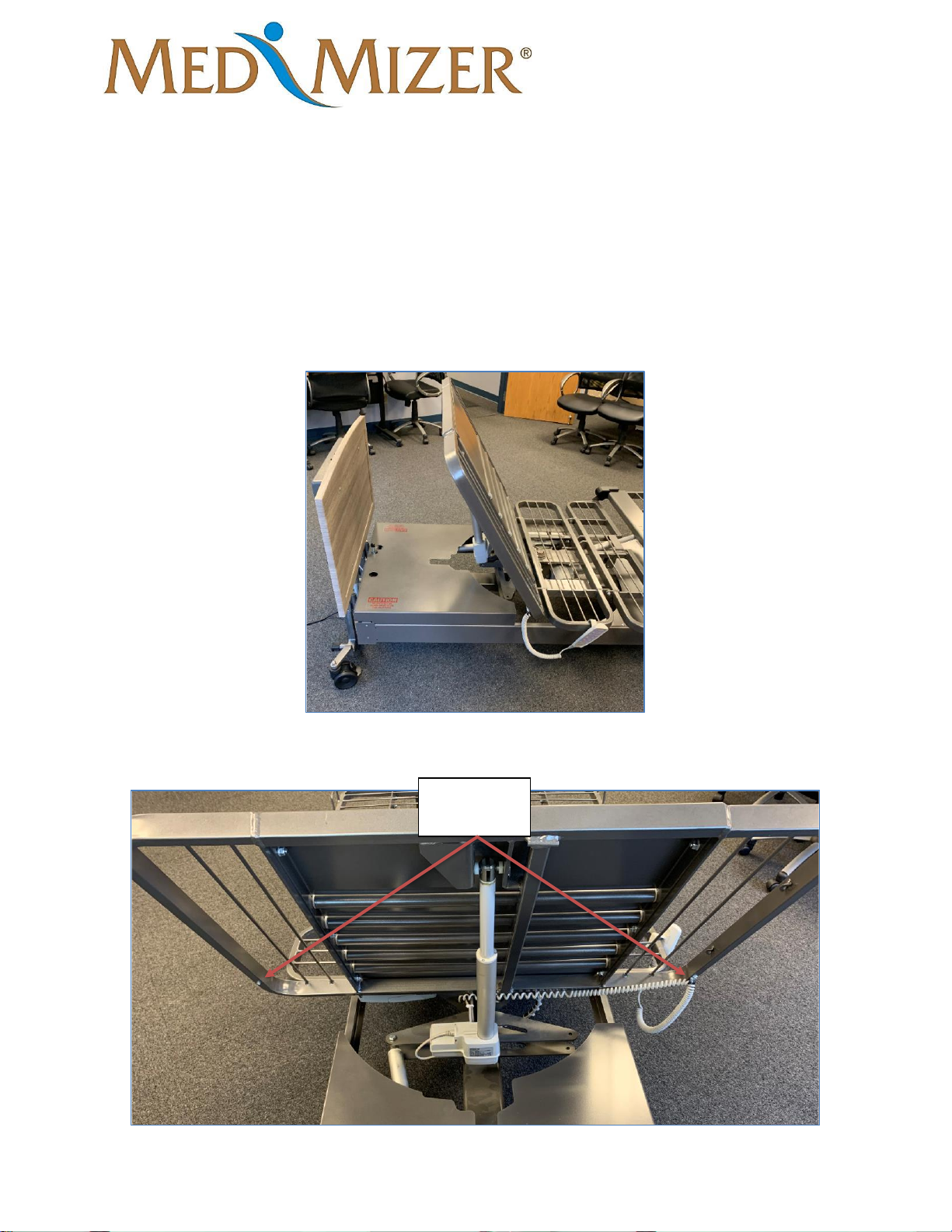
1. Raise head of the bed all the way up and locate pendant.
2. Locate the two attachment points for on the back of the head section.
Attachment
points
Page 25
ActiveCare - Standard
User Manual
MAN-ActiveCare REV03 ActiveCare Standard USER MANUAL Page 25 of 33
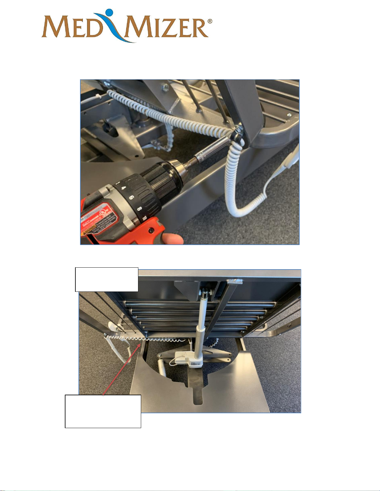
3. Unscrew the pendant clip and move to the opposite side of the head section.
Note: Ensure pendant cord is not wrapped around the head actuator
Pendant moved to
opposite side
Make sure pendant
cord is not wrapped
around actuator
Page 26
ActiveCare - Standard
User Manual
MAN-ActiveCare REV03 ActiveCare Standard USER MANUAL Page 26 of 33
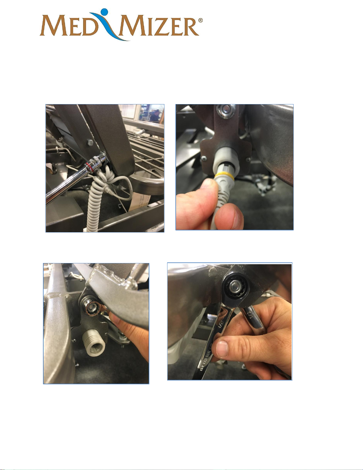
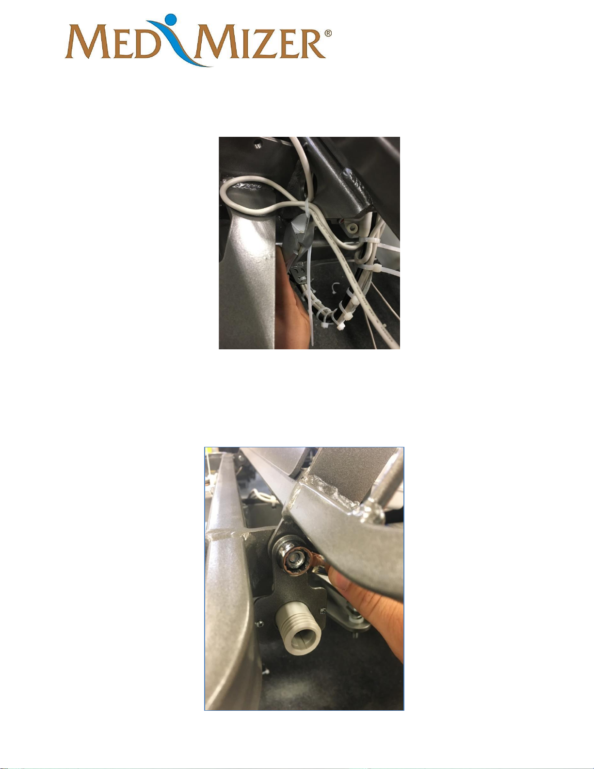
Bed with Trend Handset:
1) Remove wire clamp from bottom of head sleep surface using a 5/16 socket. And unplug
pendant.
2) Using two 1/2-inch wrenches, remove the nut from pivot bolt for the head sleep surface.
Remove the pendant cable mounting plate from the bolt and replace the nut and re-tighten.
Page 27
ActiveCare - Standard
User Manual
MAN-ActiveCare REV03 ActiveCare Standard USER MANUAL Page 27 of 33
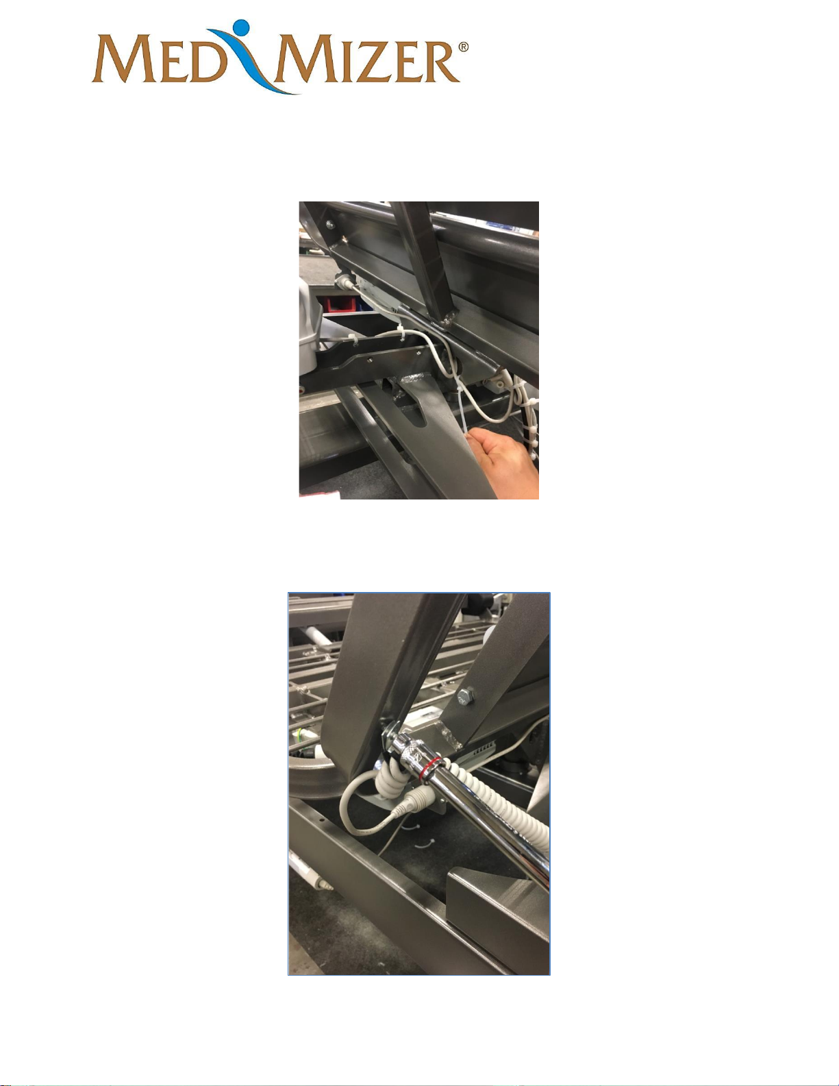
3) Cut the cable tie pictured to release excess cord.
4) On the left side of the bed, remove the pivot nut using two 1/2-inch wrenches as done on the
right side. Route the pendant cord to the left side of the bed in the same fashion as pictured
and hang the mounting bracket on the bolt. Re-tighten the nut while keeping the mounting
bracket hanging straight down.
Page 28
ActiveCare - Standard
User Manual
MAN-ActiveCare REV03 ActiveCare Standard USER MANUAL Page 28 of 33
5) Using a cable tie, remove the extra slack in the cable by fastening it in the same location as
the excess cable was tied originally. Be sure the cable slack is removed where it is routed across
the bed to prevent the cable from being pinched during normal bed operation.
6) Plug pendant back into the cord. Using a 5/16 socket, remove the self-tapping screw located
under the head sleep surface rail on the left side of the bed.
Page 29
ActiveCare - Standard
User Manual
MAN-ActiveCare REV03 ActiveCare Standard USER MANUAL Page 29 of 33
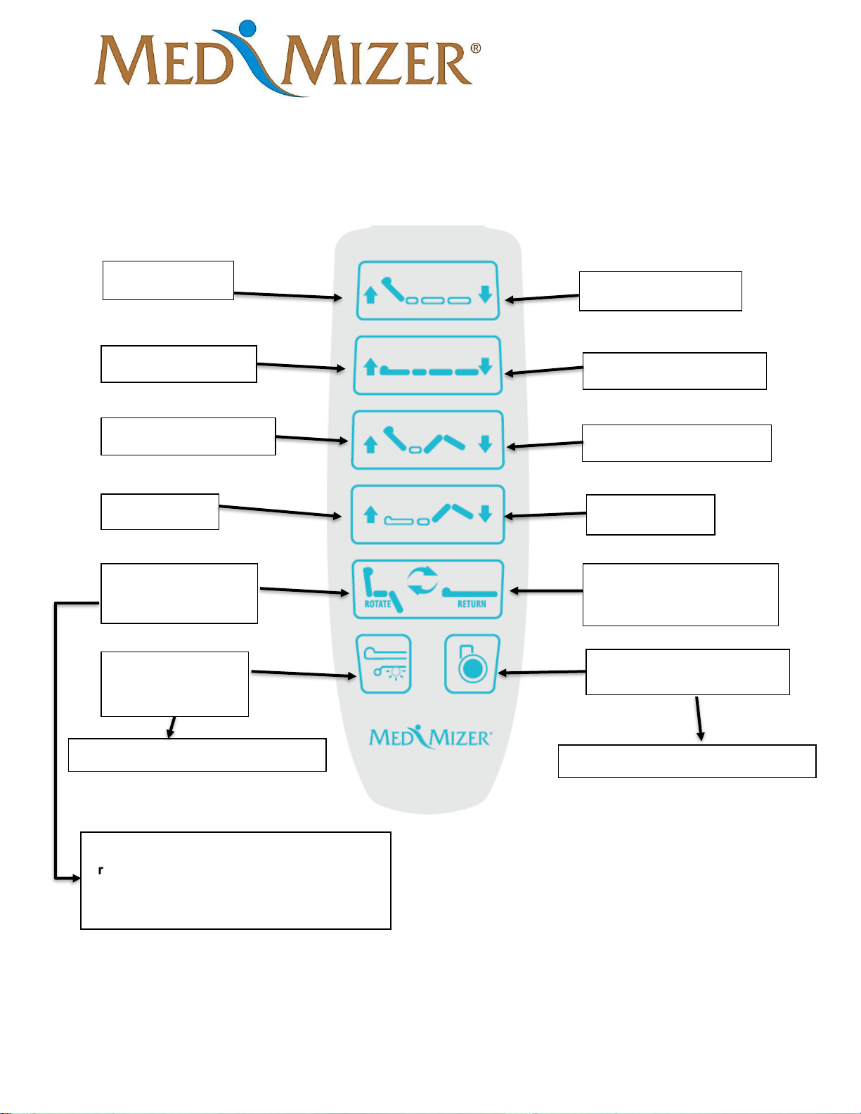
Control Options
Hand Pendant Control
Backrest Up
Backrest Down
Bed Height Up
Bed Height Down
Auto-Contour Up
Auto-Contour Down
Knee Up
Knee Down
Rotate Bed into
Chair Position
Return Bed to
Normal Bed Position
Under Bed
Lights Switch
Transport Mode
NOTE: Hold button to rotate entirely, once
rotated entirely release button. Then press
and hold button again to lower the legs to a
complete chair position.
Only available on the Deluxe Bed
Only available on the Deluxe Bed
Page 30

ActiveCare - Standard
User Manual
MAN-ActiveCare REV03 ActiveCare Standard USER MANUAL Page 30 of 33
Bed Transport
To transport an unoccupied bed, unlock the casters and use the footboard or headboard to move
the bed, do not move the bed using the rails, handheld pendant or assist bars as handles. When
bed is moved into intended space, lock casters.
NOTE: The bed is not intended to provide a means for transport of the occupant.
CAUTION: Never operate bed while casters are unlocked.
Maintenance
Cleaning
The frame can be cleaned/disinfected with a disinfecting wipe. Disinfectant should always be
applied to a cloth; never spray directly on frame or controls. After applying cleaning agent, allow
the surface to dry prior to placing unit back in service. Clean frame as needed.
Maintenance and Service
NOTICE: RECOMMENDED TO PERFORM PREVENTIVE MAINTENANCE EVERY 12
MONTHS FOR BEST PERFORMANCE.
1. Inspect the frame for weld cracks or tears.
2. Check that all bolts, pins and fasteners are still in working order.
3. Perform functional test on the frame.
4. Inspect the casters for wear and tear.
Preventative Maintenance Inspections
Problem Resolution
Inspect bed frame for cracks, tears or bending,
particularly at welds and joints.
Remove bed from service. Contact Med-Mizer®
customer service.
Inspect electrical enclosures for cracks or other
damage.
Remove bed from service. Contact Med-Mizer®
customer service.
Check that screws, bolts, pins and other fasteners are
in place, secured and properly tightened.
Remove bed from service. Tighten loose bolts and
screws. Contact Med-Mizer® customer service to order
missing or damaged fasteners.
Inspect actuators for excessive wear and
misalignment.
Remove bed from service. Contact Med-Mizer®
customer service.
Inspect power cord for damage including the plug
and strain relief.
Remove bed from service. Contact Med-Mizer®
customer service to order replacement power cord.
Page 31

ActiveCare - Standard
User Manual
MAN-ActiveCare REV03 ActiveCare Standard USER MANUAL Page 31 of 33
Verify that cables and wires are properly retained and
clear of moving parts.
Remove bed from service. Securely retain wires so they
are clear of moving parts. Contact Med-Mizer® customer
service to order replacement missing or damaged wire
fasteners.
Verify the plug connectors for the controls, drive
motors, and motor control box are fully engaged.
Fully engage connectors that are not properly engaged.
Verify the side rails/ assist bars latch securely in the
raised position.
Remove bed from service. Contact Med-Mizer®
customer service.
Verify all casters securely lock when activated.
Remove bed from service. Contact Med-Mizer®
customer service to order replacement non-locking
casters.
Verify that all bed control switches operate correctly.
Contact Med-Mizer® customer service.
Service Parts List
Contact Med-Mizer® customer service at (877) 867-7365 to order parts
PART
DESCRIPTION
6201
LINAK POWER CHORD 11 FOOT W/ GROUND CABLE (912143)
6947
HI/LO BARIATRIC ACTUATOR (400504000A0M0G26+12DB16134200)
6948
HI/LOW & HEAD (400402500A0M0G26+31DB142322000)
6949
KNEE ACTUATOR (400400550A0M0B26+11DB129342000)
6950
PIVOT ACTUATOR (400904000A0M0G26+11DB161332000)
6951
LEG ACTUATOR (400401300A0M0B26+11DB130012000)
6952
CONTROL BOX (CO61-U047-01)
6955
HB8X348-00 Active Care Handset Full
6958
CONTROL BOX MOUNTING BRACKET (1015W1001-C)
6974
POWER JUNCTION BOX - PJ2+19200S00000
7006
ACTUATOR CABLE HEAD/KNEE MOTOR 750MM (00914681-750-B)
7007
ACTUATOR CABLE PIVOT MOTOR 1575MM (00914681-1575)
7008
ACTUATOR CALE LEG MOTOR 600MM (00914681-600)
7009
ACTUATOR CABLE HI/LOW 3100MM (0965344-A)
7058
COVER, KNEE PIVOT LEFT
7059
COVER, KNEE PIVOT RIGHT
7213
4" DUAL WHEEL TOTAL LOCK CASTER BLACK
7174
CHERRY BOARD
7175
RIFT OAK BOARD
7176
OBSIDIAN BOARD
Page 32

ActiveCare - Standard
User Manual
MAN-ActiveCare REV03 ActiveCare Standard USER MANUAL Page 32 of 33
Troubleshooting
Issue
Potential Cause
Potential
Correction
The bed does not respond to the remote control.
The remote control is
not connected properly.
Reinstall the remote into
the female port in the
center of the control box
or on the head section
pivot for beds with
Trend
The remote is installed, but still no functions.
Defective Remote
Control
Replace remote with all
cables needed.
Loose actuator
connections
Ensure all actuators and
cabling are connected
properly.
Defective Control Box
Replace control box
Only some of the functions work but not all.
Actuator cable is loose
Reinstall actuator with c-
clip
Actuator is damaged
Replace actuator
Remote control is
defective
Replace hand control
Defective Control Box
Replace control box
Bed makes beeping sound with no function.
Motors need to be re-
initialized
See "Motor Re-
Initialization" in manual
Control Box Reinitialization (If needed)
To reinitialize the bed, hold down the Head up and down control buttons for 10 seconds until the
beeping stops (first row of buttons on pendant.) This will reset the control box. Once this is
reset the bed will need to be initialized. To perform this, hold the auto contour up button (third
row of pendant) several seconds until the head and leg raise up slightly, then hold the auto
contour down button until the bed returns to the flat position. Once the bed is flat hold the caster
button (bottom right button) until the bed lowers completely. Once the bed is all the way down
raise the bed back up several inches using the Bed height up button. At this point the bed should
be reinitialized and should function properly once raised back up.
Page 33

ActiveCare - Standard
User Manual
MAN-ActiveCare REV03 ActiveCare Standard USER MANUAL Page 33 of 33
Warranty
Med-Mizer, Inc. warrants to the original purchaser that its products shall be free of defects in
material and workmanship for a period of Lifetime on welds: 15 years on the bed frame: 2
years on the drive system; 1 year on wood products, casters, handsets, and miscellaneous
parts. Med-Mizer’s obligation under this warranty is expressly limited to supplying
replacement parts for, or replacing, at its option, any product which is, in the sole discretion
of Med-Mizer, found to be defective. This warranty does not cover failure due to negligence,
accident, abuse or installation not in accordance with the company’s instructions or failure to
follow maintenance instructions.
If requested by Med-Mizer, products or parts for which a warranty claim is made shall be
returned prepaid to Med-Mizer’s factory. Any improper use or any alteration or repair by others
in such manner as in Med-Mizer’s judgment affects the product materially and adversely shall
void this warranty.
 Loading...