

Page 1
Shenzhen Med-link Electronics Tech Co,.Ltd
Address: 4th and 5th Floor, Building Two, Hualian Industrial
Zone, Xinshi Community, Dalang Street, Longhua District,
518109 Shenzhen, PEOPLE'S REPUBLIC OF CHINA
Fax: +86 755-61120055 Email: [email protected]
Website: www.medxing.com
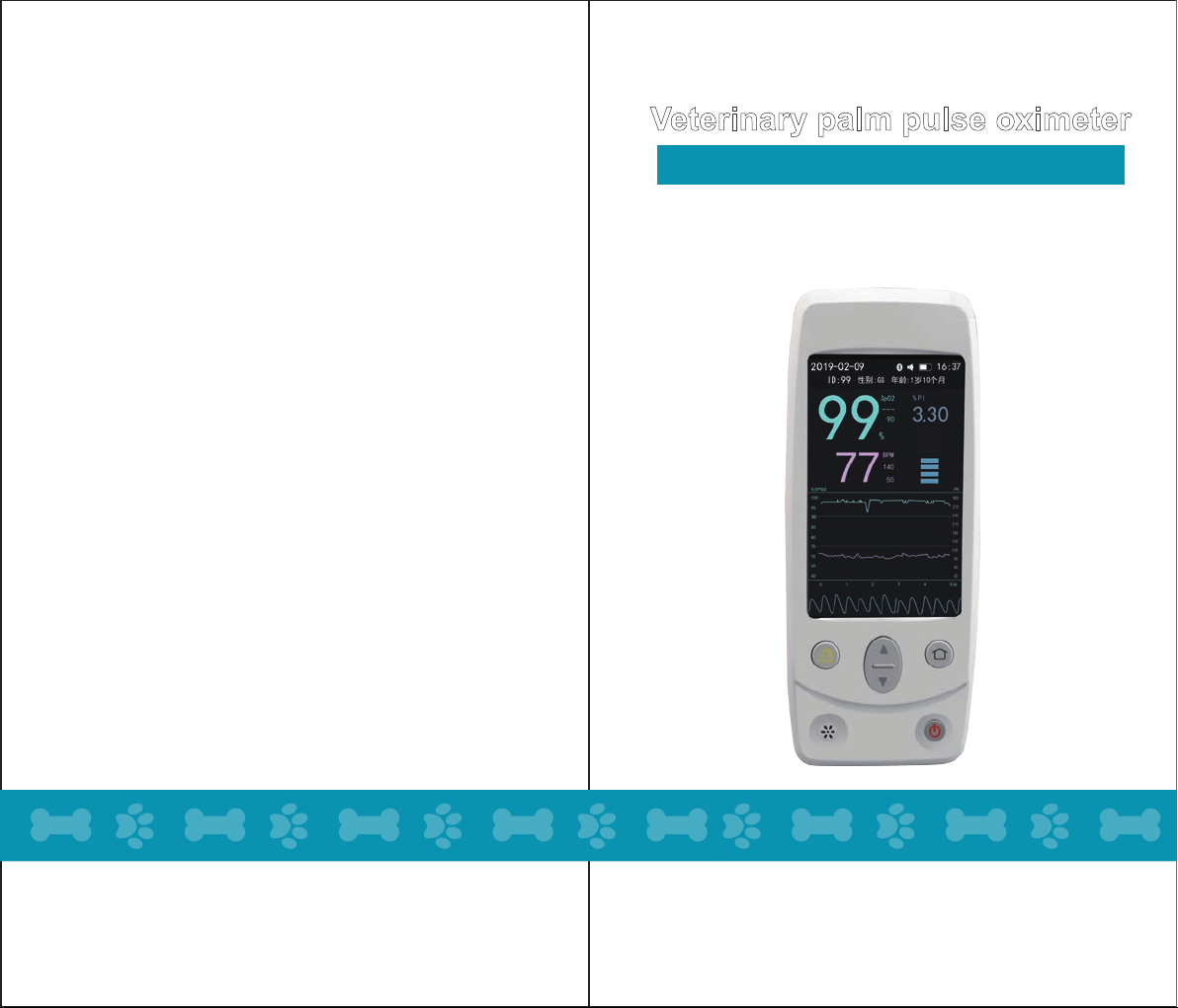
Veterinary palm pulse oximeter
COX801VB REV A.0
Revision date: October 23, 2019
manual for user
COX801VB
Please read this manual carefully before using
*Product picture is for reference only, please refer to the object
Page 2

Table of contents
1 Overview
1.1 Declaration
1.2 Product Description
1.3 Product Model
1.4 Intended use and scope of application
1.5 Contraindications
2 Product structure
2.1 Host structure composition
2.2 Key Function
3 General description of the parameters
3.1 SpO2
3.2 PR
3.3 PI
3.4 Plethysmographic waves
4 Working principle
5 Operation
5.1 Notes
5.2 Warning
6 System settings
6.1 Time setting
6.2 Brightness setting
6.3 Volume setting
6.4 Trend Map Interval Settings
6.5 Animal Information Settings
6.6 Alarm Settings
6.7 Communication Mode Settings
6.8 Restoring factory settings
7 The host machine USES the pulse blood oxygen
sensor alarm setting
7.1 SPO2 Upper limit alarm value adjustment range
7.2 SPO2Lower limit alarm value adjustment range
7.3 PR Upper limit alarm value adjustment range
7.4 PR Lower limit alarm value adjustment range
8 Measure
8.1 Precautions
8.2 Measurement process
8.3 Start measuring
8.4 Interpretation of measurement results
8.4.1 SpO2
1
1
2
2
2
2
3
3
3
4
4
4
4
4
4
5
5
5
5
6
6
6
6
6
6
6
6
8.4.2 PR
8.4.3 PI
8.4.4 Bar chart display area
8.4.5 Trace wave display area
8.4.6 Module status display area
8.4.7 Date display area
8.4.8 Time display area
8.4.9 Battery display area
8.4.10 The blood oxygen pulse rate trend chart display area
8.5 Reasons for inaccurate measurement results may be
8.6 Warning
8.7 Result of a measurement
9 Alarm System
9.1 Overview
9.2 Warning
9.3 Alarm light
9.4 Alarm sound characteristic
9.5 Alarm system deactivated
10 Technical specifications
11 Maintenance and cleaning
11.1 overview
11.2 Cleaning and maintenance of blood oxygen meter
11.3 Cleaning and disinfection of accessories
11.4 Precautions
12 Warranty
12.1 Maintenance Method
12.2 Exemptions and restrictions
12.3 Non-warranty principle
12.4 Special requirements for warranty time
13 Repackage
7
7
7
8
8
8
8
14 About after sales
14.1 Product registration / after sales information
14.2 open box to check
14.3 Packaged goods
Product Maintenance Card
Warranty Regulation
9
10
11
11
11
11
11
11
11
11
11
11
11
12
12
12
12
12
12
13
14
14
15
19
19
19
19
20
20
20
20
21
21
21
22
22
22
22
25
26
Page 3
1 Overview
* Please read the manual carefully before using this product.
1.1 Declaration
*This intellectual property copyright belongs to Shenzhen Med-link Electronics Tech Co., Ltd
(hereinafter referred to as the Med-link.
Disclaimer: The company owns all copyrights in this document, including published and
unpublished documents, and classifies the document as a confidential document. This
document is intended to be used as a reference, operation, and understanding of the
company's product or component repair policy. Any use for promotional or any other
misconduct will be considered illegal. In order to prevent infringement, the company has the
right to protect its legal rights and interests through legal channels in accordance with the
provisions of the Copyright Law. No partner may copy, use or disclose the information to any
other third party without the written authorization of the company. Our company is not
responsible for any illegal incidents or issues involving third party interests. In addition, all the
information contained in this manual has been confirmed. The company does not assume any
responsibility for accidental injury or life-threatening caused directly or indirectly due to
improper use or operation. All information contained in this manual is protected by law. Any
changes or modifications in the contents of this manual are subject to change without notice.
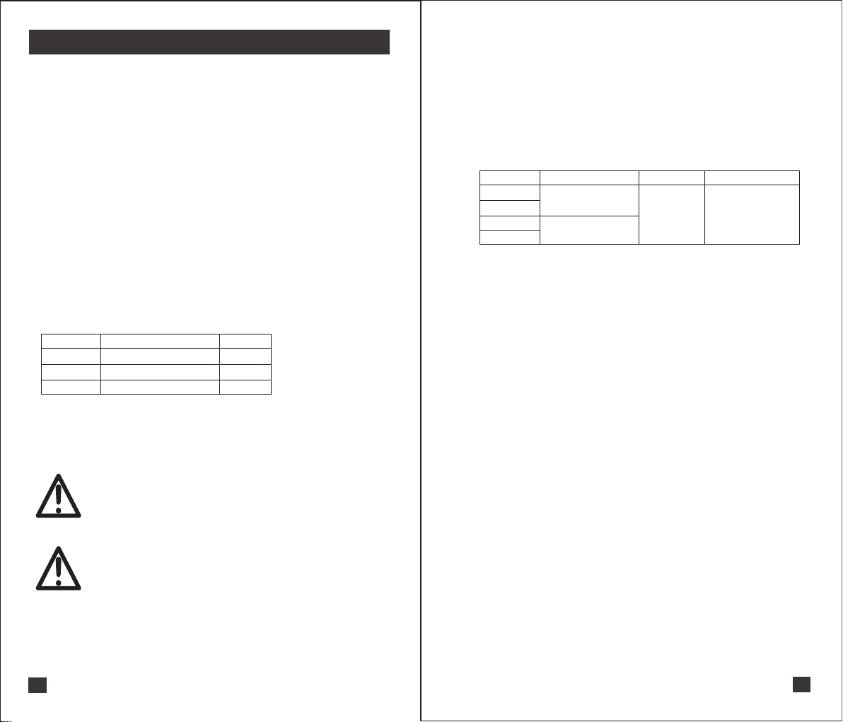
The definitions of the following symbols shown in this manual:
Symbol
SpO2
PI
PR
The materials used for the pulse oxycarbon oxygen saturation sensor or the pulse oxycarbon
oxygen saturation sensor and the contact part of the main casing and the human body are
TPU, ABS, and silica gel. These materials have been tested to comply with relevant national
regulations.
Note
Warning
Name Meaning
Arterial oxygen saturation
Perfusion Index
pulse rate
Note:
1.Technical parameters are subject to change without notice;
2.The circuit diagram, parts catalog, schematic diagram, calibration rules, etc.of the
product are only authorized by our professional engineers;
3.The product is calibrated at the factory and does not require calibration of the product
during use;
4.To ensure the accuracy of the probe measurement, replace the probe once a year.
Warning:
Please use the accessories specified by our company (see Appendix P);
Please note that this product is only used for veterinary.It can not be used for
human clinical!
If it is used for human rather than animal by the users and caused the direct
or indirect injury. Users should be totally responsable for it. It has nothing to do
with us!
Unit
%
%
BPM
1.2 Product Description
The COX801VB is a hand-held pulse oximeter that uses non-invasive measurement of
transmission.
A monitor that measures SpO2, PR, PI, pulse wave intensity, and pulse wave using a pulse
oximetry sensor.
The COX801VB features continuous measurement on a 5-inch TFT screen. The COX801VB
provides two display states for both horizontal and vertical screens.
1.3 Product model
Model
Main model
COX801VB
Cover model
COX802VB
Difference
Bluetooth module
No bluetooth module
structure Measuring principle
Handheld Transmission method
1.4 Intended use and scope of application
The pulse oximetry sensor can detect or continuously detect non-invasive SpO2, PR, PI,
etc. of the animal.
This product can be used in hospitals, homes, medical clinics, mobile medical aid
stations, etc.
1.5 Contraindications
Since the non-invasive pulse and blood oxygen saturation measurement are based on
●
the pulsation of the small arteries, the tester's blood should ensure a steady flow. When
a subject is weakly perfused due to vibration, low temperature environment, major
bleeding, or medication using systolic blood vessels, the waveform displayed by the
device will shrink and, therefore, sensitively interfere with the measurement of the
product.
9 kinds of heavily diluted colored drugs, such as: blue, indigo, green and acidic indigo
●
methylene, or carboxyhemoglobin, or methionine, or hemosin and some jaundice,
Measuring pulse oximetry with this device can lead to erroneous results.
Related drugs such as dopamine, procaine, prilocaine, lidocaine and budacaine tend to
●
be factors that affect serious errors in pulse oximetry.
●
Shock, anemia, hypothermia or the application of vasoconstrictor drugs cause arterial
blood flow to drop to an unmeasurable level;
●
Intravascular stains such as phthalocyanine or methylene blue may affect the
measurement.
Do not fix the sensor of this product in a location where the animal has tissue damage.
●
Not suitable for use in animals allergic to TPU, ABS, silicone plastic.
●
1
2
Page 4
2 product structure
This product consists of a host + accessories.
The host part includes: a display screen, a control button, and a lithium battery, which can
monitor the animal's SpO2, PI, PR, pulse wave intensity, and pulse wave shape.
Accessories for this product include: pulse oximetry sensor, Type-C line, see the attached list
for details.
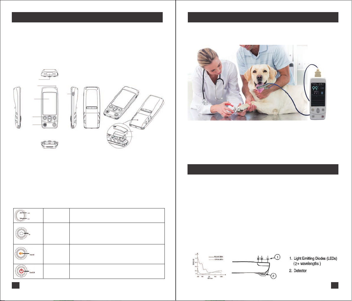
2.1 Host structure
血氧探头接口
报警指示灯
显示屏
按键
喇叭
(1)The sensors connected to the oximetry probe interface are listed in the attached list.
(2)The indication status of the alarm indicator is shown in the alarm indicator.
(3)The display is a 5-inch TFT display.
(4)Press the button to see the button function.
(5)See the alarm sound and the sound of the horn.
(6)Type-C power adapter charging port is shown in Appendix F.
(7)See Appendix F for lithium-ion batteries.
2.2 Key Function
Key
Key
Key
Key
3
Type-C
Up/down key
Set/confirm key
Alarm key
power button
Figure 1
Function: mainly used for parameter selection and adjustment,
Know <<Alarm Line Value Settings>>, <<System Settings>>
for details.
Function: Mainly used to enter the alarm parameter setting
function and enter the system setting interface,
know <<Alarm Line Value Settings>>, <<<System Settings>>
for details.
Function:mainly used for the pause of alarm or the activation
of alarm pause.
know <<Alarm Line Value Settings>>, <<System Settings>>
for details.
Function: It is mainly used for the switch of the device. Press
and hold for 2 seconds to turn off the power when the power
is turned on.
3 general description of the parameters
3.1 SpO2
COX801VB can continuously measure arterial oxygen saturation without non-invasive. Usually
a sensor is placed in the test site and connected to the COX801VB by cable.
3.2 PR
The COX801VB continuously measures pulse rate continuously.
Figure 2
3.3 PI
COX801VB can continuously measure the perfusion index without non-invasive.
3.4 plethysmographic wave
COX801VB continuous non-invasive measurement of plethysmographic waves
4 Working principle
The measurement principle of this product is spectrophotometry.
(1)Differences in the absorption of visible light and infrared light by oxyhemoglobin,
deoxyhemoglobin and plasma.(Such as figure 3)
(2)The amount of arterial blood varies with the pulse, so the amount of light absorbed by
different numbers of arterial blood also changes.
The COX801VB uses a 2-wavelength sensor to distinguish between oxyhemoglobin,
deoxygenated hemoglobin and plasma in the blood. The light of the light-emitting diode of the
COX801VB using the two-wavelength sensor is transmitted to the photodiode through the
measurement site, and the electrical signal obtained by the photodiode through the light
absorption change in the blood pulsation cycle is transmitted to the COX801VB, and the
COX801VB calculates the pulse rate according to the electrical signal returned by the sensor,
Pulse oximetry, perfusion index, plethysmographic wave, bar graph, etc.(Such as figure 4)
Figure 3
Figure 4
4
Page 5
5 Operation and use
5.1 Notes
(1) Ensure that this equipment is kept away from dust, vibration, corrosive substances, explosive
materials, high temperature and high humidity.
(2) After the COX801VB gets wet, stop using it.
(3) Do not use this product immediately if it is transferred from a low temperature environment to
a high temperature environment.
(4) The front panel buttons of this product cannot be operated with sharp materials.
(5) Do not immerse the device in a liquid. If you need to clean the product, wipe the surface of the
device with a soft cloth dampened with disinfectant. Please do not spray any liquid directly on this
device.
(6) When the oximeter is turned on, if the interface is not displayed or the information that should
be displayed is incomplete, stop using the oximeter. Next, please contact a qualified service
person, the agent of the local US company or directly contact the company's service department.
5.2 Warning
(1)Please do not use this oximeter in flammable and explosive anesthetic gases, oxygen,
nitrous oxide, etc.;
(2)To ensure the performance accuracy of this product and prevent malfunction of the
device, please do not use it in very humid places;
Warning
(3)Physiological conditions, treatment protocols, or external agents can interfere with the
detection and measurement of the oximeter, including hemoglobin dysfunction, arterial
staining, weak perfusion, melanin, and externally applied colored stains.
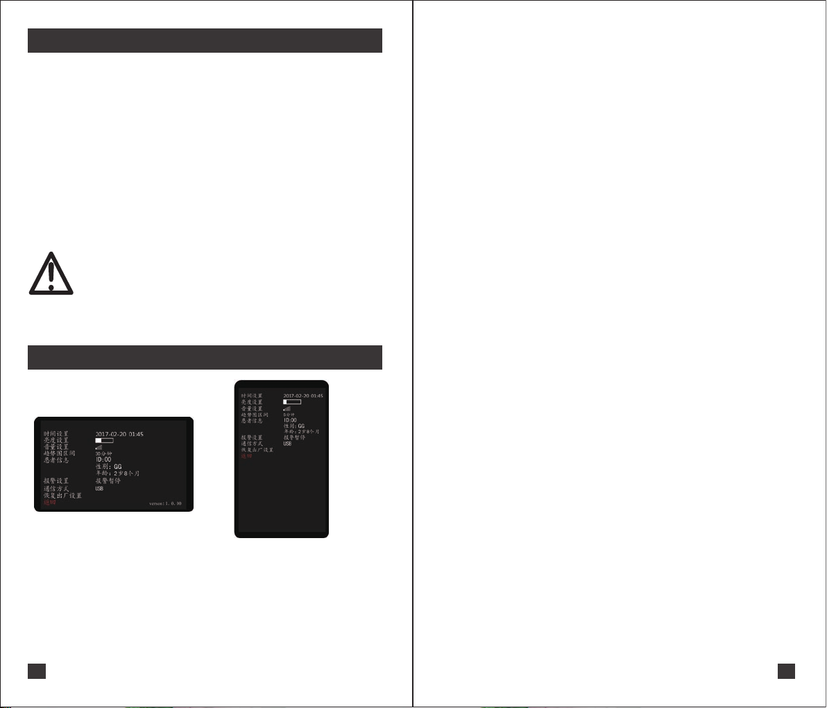
6 System settings
In the power on state, short press to enter the
setting interface:
Figure 5
(1)Setting contents include: time setting, brightness setting, volume setting, Trend Map Interval
Settings, animal information setting, alarm setting, communication mode, recovery of factory reset
and return
(2)Press up/down to select the content to be set. The selected setting item is displayed in red font;
Press the set/confirm key to enter the second level sub-content setting on the right side, and the
triangle icon appears, and then press the up/down key to set the sub-content; After setting, press
the set/confirm key, then the setting is completed.
(3)Select "back" Settings and exit the Settings screen.
5
6.1 Time setting
When the instrument is used for the first time, please set the correct time and date. Time and date
are important indicators of the measurement results.
Follow the steps below to set it up:
(1)Under the setting interface, press up/down button to select "Time Setting",and then press the
"setting/confirm" key to start setting the time "year";
(2)Press the up/down key to adjust the value of "year",then press the set key to switch "month" ->
"day" -> "hour" -> "minute" successively for setting. The time shows the 24-hour system.
6.2 Brightness setting
(1)Under the setting interface, press the up/down key to select"Brightness Setting";
(2)Click the setting/confirm button to select the setting brightness;
(3)Press the up/down to adjust the brightness, there are 18 levels in total, and the factory default
level is three.
6.3 volume setting
(1) Under the setting interface, press the up/down key to select "volume Settings";
(2) Click the setting/confirm button to select "volume settings";
(3) Press the up/down to adjust the volume, there are six levels, the factory default level is one
(It's silent mode).
6.4 Trend Map Interval Settings
(1) Under the setting interface,Press the up/down key to select "trend interval";
(2) Click the setting/confirm button to set the "trend interval";
(3) Press the up/down key to adjust the trend chart interval. There are six levels,which are 5
minutes /30 minutes /1 hour /6 hours /12 hours /24 hours. The factory default is 5 minutes.
6.5 Animal Information Settings
(1) Under the setting interface, press the up/down key to select "Animal Information";
(2) Click set/confirm key, select ID number setting, and press up/down to adjust ID number 0-99;
(3) Click the up/down key to select the gender;
(4) Click set/confirm to enter age selection. Press up/down to adjust age to X years and X months.
6.6 Alarming Settings
(1) In the setting interface, press up/down key to select "alarming setting";
(2) Click the set/confirm button to select the "Alarming Settings" time;
(3) Press the up/down key button to adjust the "alarming setting" function. There are two modes:
"alarming pause" and "alarming off". If the alarm is enabled, you need to enter the corresponding
password to activate (password: 1 2 3 4 5 6 ); factory default is alarming pause and the pause
time is 120s. (Non-professionals should not use the "alarming off" function)
Attention: When "Alarming Pause" is selected, the default "Alarming Off" is inactive.
6.7 Communication mode setting
(1) In the setting interface, press up/down key to select "Communication Method";
(2) Click the set/confirm button to select "Communication Method";
(3) press up/down key button can be adjusted to communicate by USB or Bluetooth.
6.8 Restore factory settings
(1) In the setting interface, press up/down key to select "Restore factory settings"
(2) Click the set/confirm button to select "Restore Factory Settings" and default "Cancel";
(3) Press the up/down key to select "Cancel" / "OK";
(4) Select "OK" and click the set/confirm button to restore the factory settings and restore the
brightness, sound,Trend Map Interval Settings and alarming limits.
6
Page 6
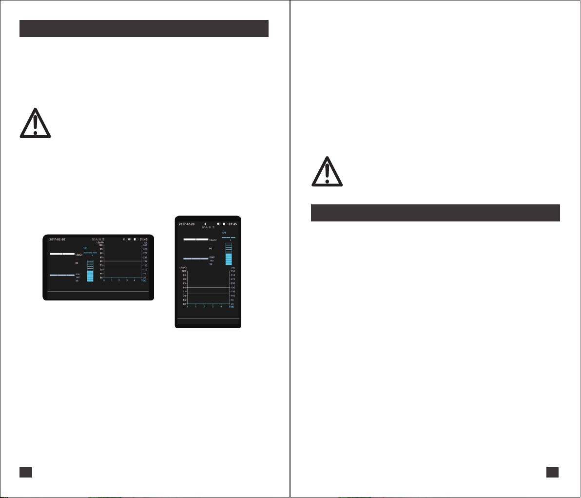
7 The host uses Spo2 sensor alarming settings
Overview:
The alarming system of this product has only a set of alarm preset alarm limits. See the factory
default alarming limit (Appendix H) for details.
Alarming limits can be changed and saved with the following alarming limit settings.
Alarming limit value previously saved will be used by default for each start-up of the power-on
alarming system.
If you want to restore the factory default alarming limit, please refer to <<Reset to Factory
Settings>> of <<System Settings>>.
Warning: Please observe whether the current alarming limit is in compliance with
this animal before use.
Note: When the power supply loses at any time, powering up again and starting
Warning
(1)Under the main menu interface, press the set/confirm button for 2 seconds to enter the
alarming Settings menu, as shown in the following figure;
(2)The short press the set/confirm button can switch the alarming value to be set, and the order
is as follows:
SpO2 upper limit alarming value-> SpO2 lower limit alarming value-> PR upper limit alarming
value-> PR lower limit alarming value-> Exit and save alarming value Long Press set/confirm
button can exit and save the alarming value setting, press the up/down button can adjust the
corresponding alarming value.
7.1 Adjustment range of SpO2 upper limit alarming value
(1) If the lower limit of the alarming line is not valid (i.e., "--"), the upper limit of the alarming line
can be arbitrarily selected from 40% to 99% or invalid (i.e., "--").
(2) If the lower limit of alarming line is 40% ~ 97%, the upper limit of alarming line can be
selected from (lower limit of alarming line +2) ~ 99% or invalid (i.e., "--").
(3) If the lower limit of alarming line is 98% ~ 99%, the upper limit of alarming line can only be
invalid (i.e., "--").
7.2 Adjustment range of SpO2 lower limit alarming value
(1) If the upper limit of the alarming line is not valid (i.e., "--"), the lower limit of the alarming line
can be arbitrarily selected from 40% to 99% or invalid (i.e., "--").
(2) If the upper limit of alarming line is 42% ~ 99%, the lower limit of alarming line can be
selected from 40% ~ (upper limit of alarm line-2) or invalid (i.e., "--").
(3) If the upper limit of the alarming line is between 40% and 41%, the lower limit of the alarming
line can only be invalid (that is, the "--").
7
the alarming system default to using the previously saved alarming limits.
Figure 6
7.3 Adjustment range of upper limit alarming value of PR
1) If the lower limit of the alarming line is not valid (i.e., "--"), the upper limit of the alarming line
can be arbitrarily selected from 30 bpm to 350 bpm or invalid (i.e., "--").
2) If the lower limit of the alarming line is 30 bpm ~ 348 bpm, the upper limit of the alarming line
can be selected from (lower limit of alarm line +2) ~ 350 bpm or invalid (i.e., "--").
3) If the lower limit of the alarming line is 349 bpm ~ 350 bpm, the upper limit of the alarming line
can only be invalid (i.e., the "--").
7.4 Adjustment range of lower limit alarming value of PR
1) If the upper limit of the alarming line is not valid (i.e., "--"), the lower limit of the alarming line can
be arbitrarily selected from 30 bpm to 350 bpm or invalid (i.e., "--").
2) If the upper limit of the alarming line is 32 bpm ~ 350 bpm, the lower limit of the alarming line
can be selected from 30 bpm ~ (upper limit of alarm line-2) or invalid (i.e., "--").
3) If the upper limit of the alarming line is 30 bpm to 31 bpm, the lower limit of the alarming line
can only be invalid (i.e., the "--").
Warning:
If different alarming line values are used for the same or similar equipment in any single
area, there may be dangerous. For example, intensive care unit, heart operating room
and so on. Please set different alarming limits according to the condition of each tested
Warning
animal, and ensure its safety and effectiveness.
8 Measurement
Statement: Please set the system and alarming limit before starting the measurement.
8.1 Precautions
(1)The sensor used in this equipment has a wavelength of red light: 660 nm, infrared light: 905 nm. These
light waves cannot directly illuminate the animal's eyes to avoid injury. When a treatment method similar
to photodynamic therapy is used during the measurement, the wavelength may be interfered to affect the
measurement.
(2)Periodically inspect the main components and accessories of the oximeter to confirm that there are no
obvious damages that may affect the safety and monitoring performance of animal. It is recommended to
check the product before each use. If the oximeter has obvious damage, stop using the product.
(3)when monitoring the tested animals for a long time, the position of the Spo2 sensor attached should be
checked every 2 hours, and the proper movement should be carried out when the skin changes. The
same measuring point should be measured continuously for up to 4 hours. Some tested animals may
need to be examined more frequently, such as those with perfusion disorders or skin sensitivity. Because
prolonged monitoring may increase unpredictable skin changes, such as allergies, redness, blistering or
compression necrosis.
(4)If there is an emergency to turn off the equipment, remove the probe from the sensor to stop the test,
unplug all the accessories in the equipmen and turn off.
(5)Please carefully check the equipment before using this product to confirm that it can be used normally.
(6)The sensor of this oximeter should not be used in the probe or other parts of the arterial catheter, blood
pressure cuff or intravenous injection.
(7)Make sure that the light source comes from the interior of the transparent silica gel. In addition, the light
source will affect the measurement results, including fluorescent lamps, red light source ,infrared water
heaters, direct sunlight and so on.
(8)Frequent activity of the subject or interference from external radio can affect the accuracy of the test.
(9)Only use the sensor specified in this manual and follow the instructions for use. Observe all warnings
and precautions.
(10)High frequency electrosurgical equipment and defibrillators can affect the use of the equipment.
(11)Use the equipment facing the operator and within 1 meter to view the measurement parameters.
8
Page 7
Explosion hazard—Please do not use this product in a flammable or
explosive gas environments, such as anesthetic or nitrous oxide.
Please do not use this product during animal MRI and CT scans.
Warning
Please do not use this product if you are allergic to silicone and ABS plastics.
Please dispose of used mainframes, accessories and packaging materials
in accordance with local laws and regulations.
8.2 Measurement process
(1)Select the appropriate spo2 sensor according to the type, weight and wearing position of the
tested animal.
(2)Insert the sensor plug into the socket of the monitor.
(3)Clean and disinfect the parts of the sensor in contact with the tested animal.
(4)Connect the sensor to the contact part of the tested animal.
(5)Start measuring.
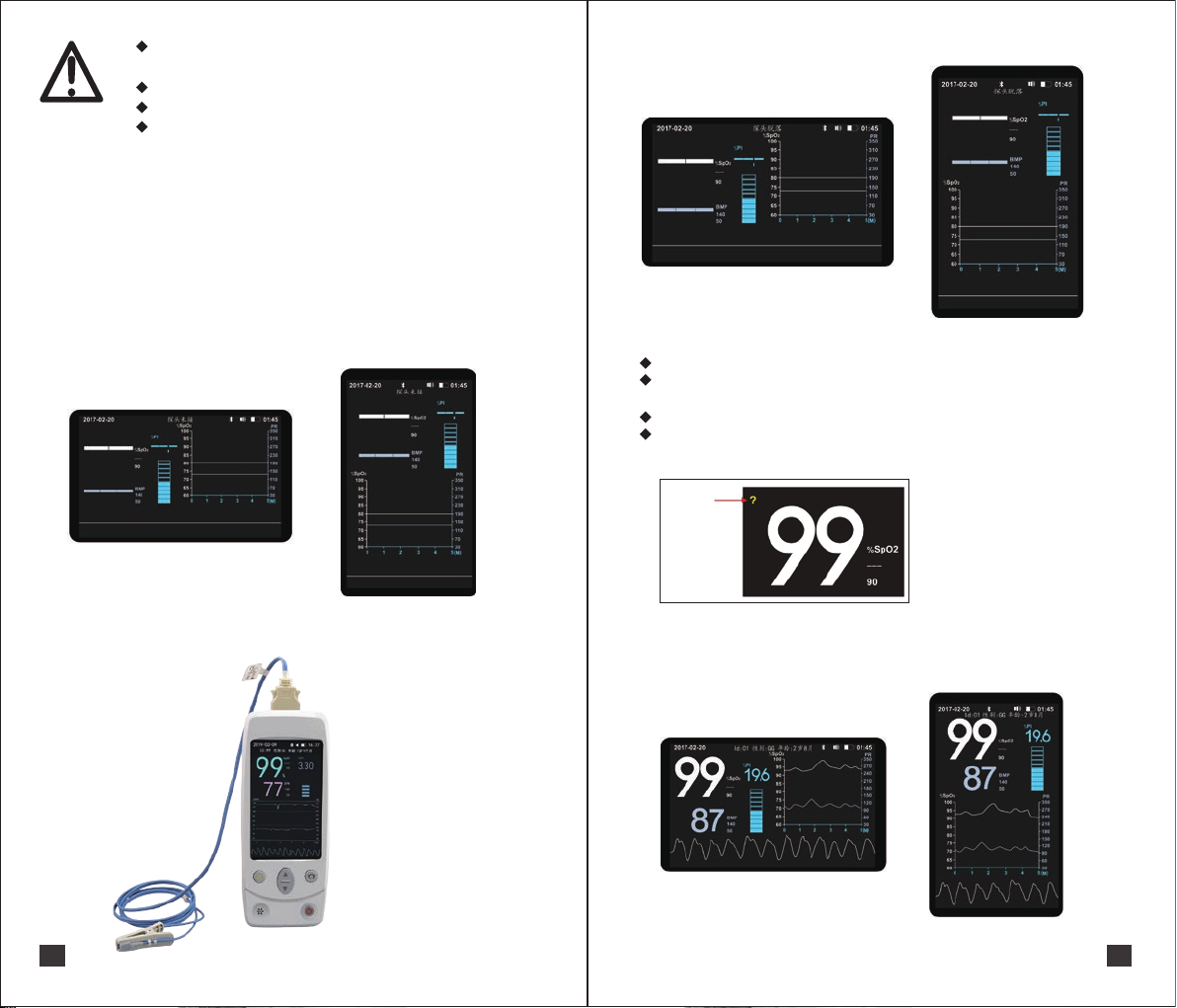
The Spo2 sensor is connected to the equipment as shown in the following figure. If the
equipment is not connected to the spo2 sensor or if the spo2 sensor is inserted incorrectly, the
"probe is not connected" will be displayed at the top of the equipment screen.
If the tested part and the probe are not in full contact,
"probe shedding" is displayed at the top of the screen
Figure 9
8.3 Start measuring
Data display interface
After connecting the Spo2 sensor for a few seconds, the measurement result is displayed
on the screen.
Horizontal vertical device can switch the display direction of the screen
The host uses a pulse carbon oxygen oximeter sensor to display content, range, resolution,
accuracy, and signal strength. See Appendix B.
weak signal
Figure 7
Prompt the user to properly connect the Spo2 sensor:
9
Figure 10
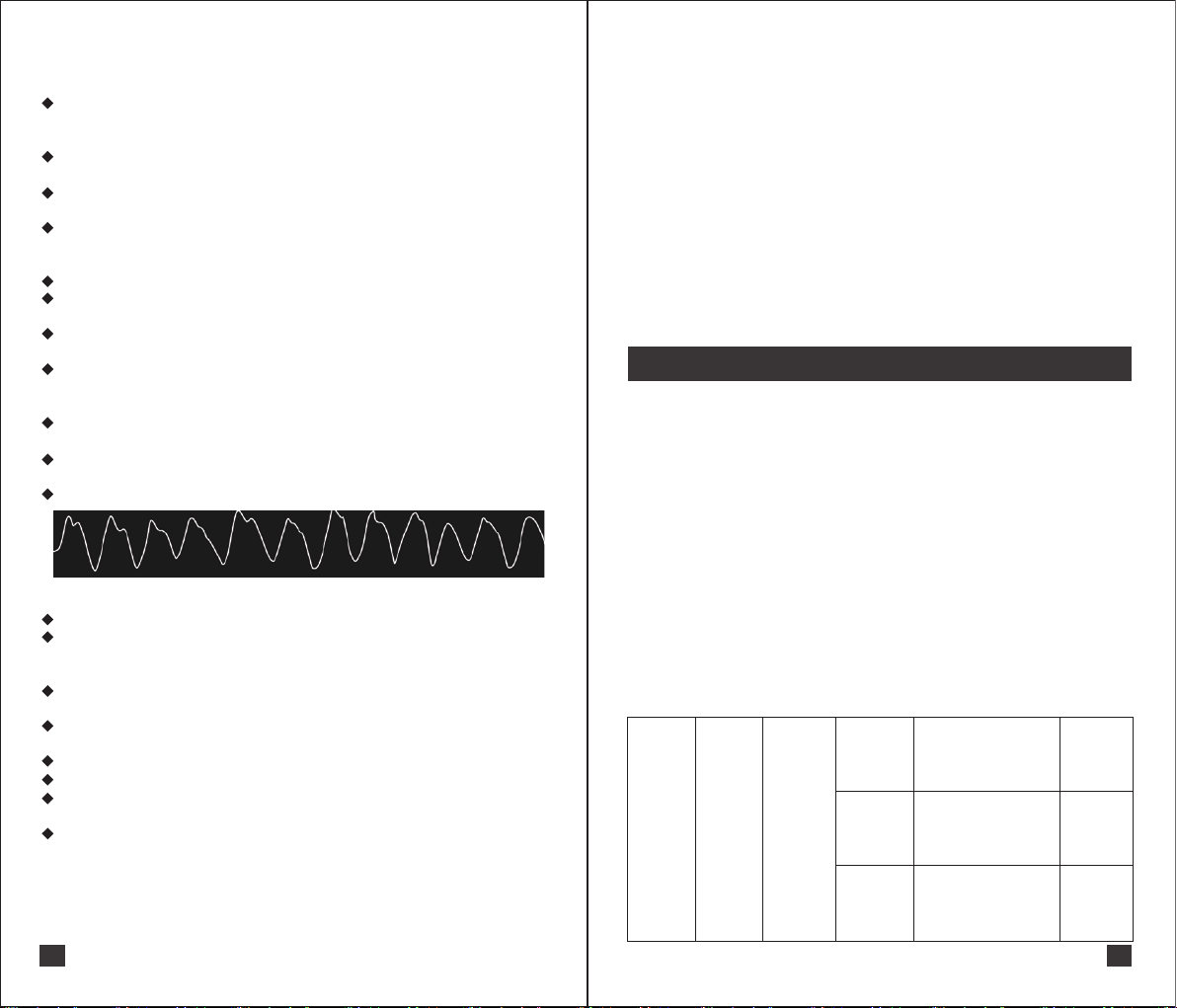
When the signal strength indicates "weak signal ", there is a "?" symbol appearing around the
SpO2. Indicates that the signal quality obtained by the Spo2 sensor is too poor or too weak. The
condition of the animal under test should be checked and the sensor placed in a suitable
location.
Figure 8: Correct connection
Figure 11
10
Page 8
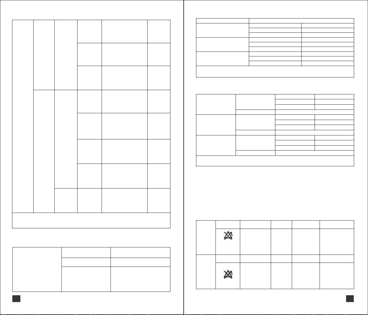
8.4 Explanation of measurement results
8.4.1 SpO2
Blood oxygen saturation (SpO2) refers to the percentage of blood oxygen-bound hemoglobin
(HbO2) in the total binding hemoglobin (Hb, hemoglobin concentration), which is an important
physiological parameter of respiratory circulation;
Spo2 alarming high limit value "---" means no ultra-high limit alarming value; SpO2 alarming
low limit value "90" means ultra- low limit alarming value;
If the measured Spo2 value is higher than the high limit value, the measured value turns
yellow, triggering an medium-level alarm;
If the measured Spo2 value is lower than the low limit value, the measured value turns red,
triggering an high-level alarm.
8.4.2 PR
Shows the number of beats of pulse per minute under normal measurement;
PR alarming high limit value "150" indicates the ultra-high limit alarming value; PR alarming
low limit value "50" indicates the ultra-low limit alarming value;
If the measured pulse rate value is higher than the high limit value, the measured value turns
red, triggering an high-level alarm;
If the measured pulse rate value is lower than the low limit value, the measured value turns
red, triggering an high-level alarm.
8.4.3 PI
Shows current blood flow perfusion capacity under normal measurement conditions.
8.4.4 Bar graph display area
Pulse amplitude indication under normal measurement.
8.4.5 Plethysmographic display area
Demonstrate pulse fluctuations under normal measurement.
8.4.6 Module Status Display Area
Display animal information under normal conditions, such as: ID: 01 gender Male Age 28;
Display the status of the module under abnormal measurement, such as: "The probe is not
connected", "The probe fault", etc.
8.4.7 Date display area
Display the current date of the device.
8.4.8 Time display area
Display the current time of the device.
8.4.9 Battery display area
Display the remaining battery power, there is a low battery prompt;
If it is less than 3.65V, the battery symbol will turn red to indicate low battery;
If it is less than 3.3V, it will automatically shut down.
8.4.10 Blood oxygen pulse rate trend graph display area
Choose to show trends in blood oxygen and pulse rate for different periods of time.
Note:
(1) The normal update period of the data is 1 second, and the invalid value is displayed if the data
is not updated for more than 30 seconds.
(2) The influence of other signal processing on the display and transmission of parameters is
within 1 second.
11
Figure 12
8.5 The inaccurate measurement results may be due to
● The improper use of Probe;
● An important indicator of hemoglobin dysfunction (such as carbonaceous hemoglobin or
methemoglobin);
● Intravascular staining exceeding the standard, such as indole cyan green or methylene blue;
● Strong ambient light such as surgical lights (especially Xenon lamps), bilirubin lamps,
fluorescent lamps, infrared light;
● High frequency electrosurgical equipment and defibrillators;
● Rhythmic beating of vein;
● Tight Spo2 sensor;
● Low perfusion index.
8.6 Warning
please use the attachment recommended in this manual(see attached list).
8.7 End of measurement
After the measurement is over, turn off the instrument.
9 Alarming system
9.1 Overview
(1) alarming signal generated by alarming system is divided into visual alarming signal and
auditory alarming signal.
(2) the visual alarming signal has indicator light alarming indication and display text alarming
indication.
(3) the alarming system is divided into three levels: high-level, medium-level, and low-level
alarms, and the alarming level cannot be changed.
(4) in addition, the alarming system also provides prompt information.
(5) the maximum delay time of the alarming system is less than 2 seconds.
9.2 Precautions
There are different between using a pulse carbon oximeter sensor and pulse oximeter sensor will
be different.
After entering the setup interface,
Audible alarm: The alarming sound is not broadcast after the alarming sound is broadcast.
The text displaying alarm: it is not displayed because it enters the setting interface.
Indicator alarm: always prompt the latest, highest priority alarm before entering the setup
interface and no longer update.
See the following table:
Host uses
Spo2
sensor
Technical
alarm
High-level
alarm
Probe is not
connected
Probe current
is too large
Probe fault
Appendix alarming indicator
characteristics; Appendix
alarming sound characteristics;
Display text alarming indication
"Probe is not connected".
Appendix alarming indicator
characteristics; Appendix
alarming sound characteristics;
Display text alarming indication
“Probe current is too large".
Appendix alarming indicator
characteristics; Appendix
alarming sound characteristics;
Display text alarming indication
"Probe fault".
The screen
display
"The probe is
not connected"
The screen
display
"The probe is
current is too
large"
The screen
display
"The probe
fault"
12
Page 9
Connected to the table:
Appendix alarming indicator
characteristics; Appendix
alarming sound characteristics;
Display text alarming indication
"Probe shedding".
Appendix alarming indicator
characteristics; Appendix
alarming sound characteristics;
Display text alarming indication
"Probe is short- circuit".
Appendix alarming indicator
characteristics; Appendix
alarming sound characteristics;
Display text alarming indication
"low battery".
Appendix alarming indicator
characteristics; Appendix
alarming sound characteristics;
Display text alarming indication
"No pulse".
Appendix alarming indicator
characteristics; Appendix
alarming sound characteristics;
Display text alarming indication
"Low SpO2".
Appendix alarming indicator
characteristics; Appendix
alarming sound characteristics;
Display text alarming indication
"High PR".
Appendix alarming indicator
characteristics; Appendix
alarming sound characteristics;
Display text alarming indication
"Low PR".
Appendix alarming indicator
characteristics; Appendix
alarming sound characteristics;
Display text alarming indication
"High SpO2".
Host uses
Spo2
sensor
Technical
alarm
Physiological
alarm
High-level
alarm
High-level
alarm
Medium-level
alarm
Probe
shedding
Probe is
short- circuit
Low battery
No pulse
The measurement
parameters of
SpO2 are lower
than the lower
limit of SpO2
alarm.
The measurement
parameter of PR
is higher than the
upper limit of the
PR alarm
The measurement
parameters of PR
are lower than the
lower limit of
PR alarm
The measurement
parameters of
SpO2 are higher
than the upper
limit of SpO2
alarm
Attention: the alarming level is not changed
Statement: the display text alarm indicates that it can be clearly observed at a distance of 1m.
9.3 Alarming Indicator
Alarming Indicator
Quantity
Color
Alarming indicator color
high-level alarm Red
medium-level alarm Yellow
low-level alarm Green
2
Red/Green
The screen
display
"probe
shedding"
The screen
display
"Probe is
short- circuit"
Battery
symbol
remaining
red
The screen
display
"No pulse”
Measurement
parameters
of SpO2
turn red
Measurement
parameters
of PR
turn red
Measurement
parameters
of PR
turn red
measurement
parameters of
SpO2
turn yellow
Alarming indicator characteristics
Alarming Level
Low-level alarm
Medium-level alarm
High-level alarm
Occupancy indicator
period
Duty Cycle
Occupancy indicator
period
Duty Cycle
Occupancy indicator
period
Duty Cycle
Indicator characteristics
Green
normally open
100%
Red, Green
About 2 seconds
50%
Red
About 0.5 seconds
50%
The alarm status of the above indicator light can be clearly observed at a distance of 4 m.
9.4 Alarm sound characteristic
Duration
Low-level alarm
Alarm sound feature
Sound pressure
Frequency
Harmonic number
About 55db
Duration
Medium-level alarm
Alarm sound feature
Sound pressure
Frequency
Harmonic number
About 60db
Duration
High-level alarm
Alarm sound feature
Sound pressure
Alarm sound pressure measurement: the sound pressure meter and the alarm generating device are
measured at a distance of about 1 m in the same plane.
Frequency
Harmonic number
About 62db
0.226 second
250Hz
Not less than 4pcs
About 1.1 second
250Hz
Not less than 4pcs
About 4.38 second
250Hz
Not less than 4pcs
9.5 Inactive alarm system
This system provides two kinds of inactive alarm shutdown and alarm suspension.
Note:
(1)The alarm sound continues until the alarm disappears or the alarm is turned off and paused.
(2)The alarm signal delay and alarm signal generation delay are less than 1 second.
(3)Warning: Do not easily use the alarm shutdown.
Screen tips Implementation Pause time Close content Activation method
Alarm
pause
Alarm
shutdown
And countdown
within 120
seconds
Click Alarm pause/
activation Key can
achieve alarm
pause
≤120
seconds
sound
alarm signal
Screen tips Implementation Pause time Close content Activation method
Shown as
chapter 6.6
Permanently
closed
Sound alarm
signal LED
indication alarm
signal,
Text alarm signal
click Alarm pause/
Activation key Can
be activated from
alarm pause or
waiting for the end
of pause time.
Shown as
chapter 6.6
13
14
Page 10
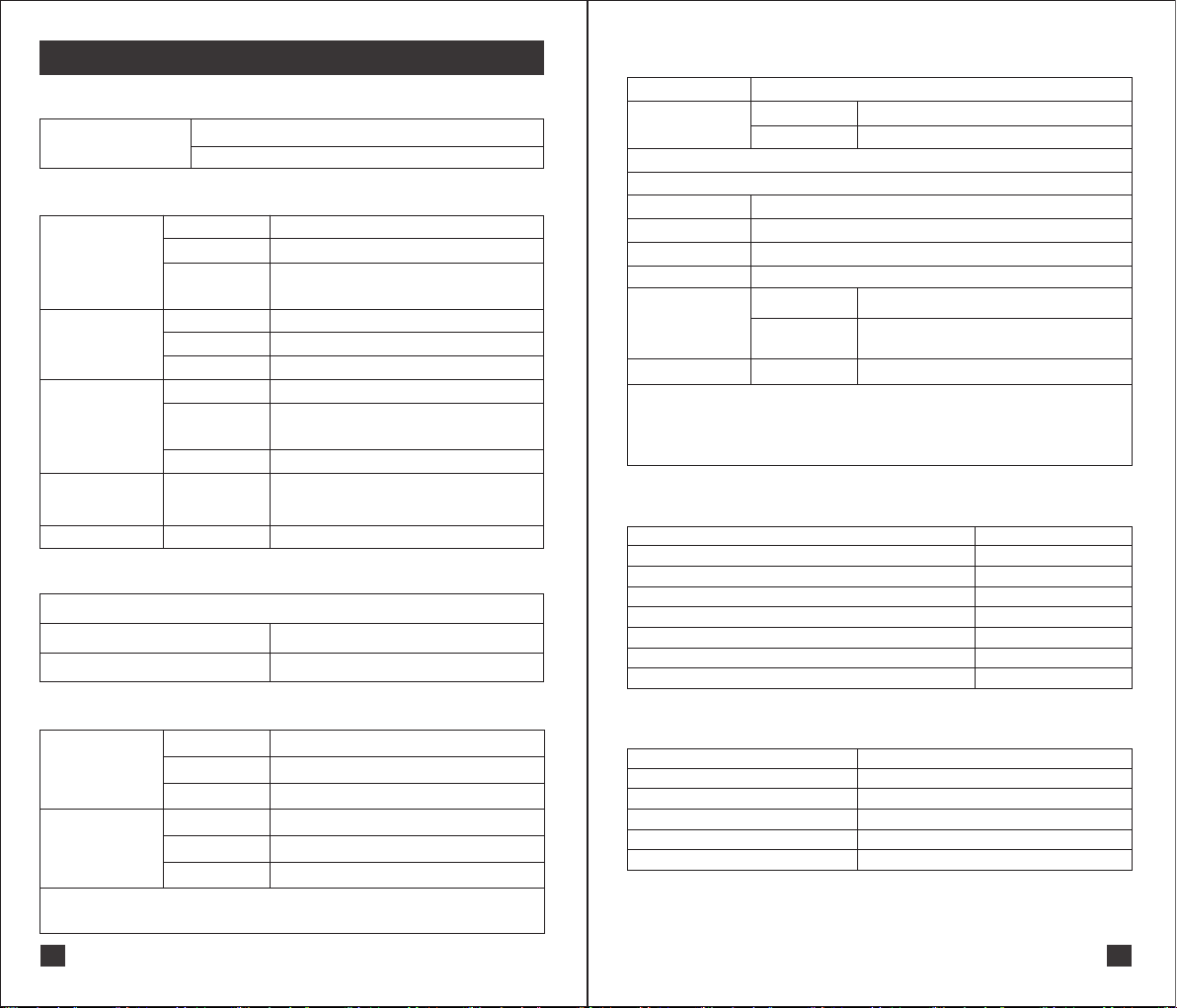
10 specifications
Appendix A
Pulse oximetry sensor
Appendix B
Pulse oximetry
SpO2
Pulse rate PR
Perfusion index PI
Signal intensity
indication
Data update cycle
Appendix C: Product specifications
weight
Specification
Wavelength: Red light: 660nm Error ±5nm; Infrared light: 905nm Error ±10nm
Power: ≤15mW
Measurement range
Display resolution
Measurement
accuracy
Measurement range
Display resolution
Measurement accuracy
Measurement range
Display resolution
Measurement accuracy
PI value is less than or
equal to 0.3% means
"weak signal weak"
displayed”?”
About1second
40%~100%
1%
Range 90% to 100%±2%
Range 70% to 89%±3%
Range <70%: NO PROVISION; follow YY 0784-2010
30 bpm~350 bpm
1bpm
±3bpm
0%~20%
When the display content is greater than or equal to 10.0,
the display resolution is 0.1%;otherwise,the display
resolution is 0.1%;
No definition
Less than or equal to 0.3% means "weak signal weak
Specifications and weight
355g
220mm×90mm×37mm
Appendix E
Power supply
Power consumption
Note: please charge the lithium battery to 3.6~3.9V and pull it out from the device if it is unused for long time (over 3 months).
lithium battery
Model
Rated voltage
Battery capacity
Service life
Long-term
transportation
storage
(over 3 months)
Power Adapter
Note: The power adapter used by the operator must comply with <<GB 4943.1-2011>>,<<YY 0709-2009>>,
<<GB 9706.1-2007>>,<<YY 0784-2010>>,<<YY 0505-2012>>.
Warning: If the lithium battery is bubbling, please stop using it and contact the manufacturer.
If the lithium battery needs to be replaced, please contact the manufacturer.
Powered by internal lithium battery
Normal work
Standby
YJ114055
3.7V
2750mAh
Cyclic charge and discharge 1000times
Environment
Storage description
OUTPUT: DC 5V 1A
≤500mA
About 35uA
Dry, cool place, Temperature: 23±5°C
Humidity: 65±20% RH no condensation
The lithium battery should be charged to 3.6~3.9V then
storaged;Besides,it should be charged and discharged
every 3 months
Appendix F: Safety specification
Classification
According to the type of electric shock protection
According to the operating mode
Device input supply voltage
Device input power
Whether the device has the proper protection against the defibrillation discharge effect
Whether the device has signal output or input section
Permanent or non-permanent installation
Device
Internal power supply
Continuous operation
DC 5V
5W
no
yes
non-permanent installation
Appendix D: Environmental specifications
temperature
Working
environment
Storage
transportation
Note: The lithium battery should be taken out from the device and storaged separately if it is unused for long time
(over 3 months), the storage environment for lithium battery is refer to attached file.
For the storage environment of the accessory sensor, please refer to the instruction manual of the accessory sensor.
humidity
Atmospheric
pressure
temperature
humidity
Atmospheric
pressure
15
5℃~40℃
0%~80% No condensation
86.0kPa~106.0kPa
-10℃~55℃
0%~80% No condensation
86.0kPa~106.0kPa
Appendix G: Factory default alarm limit
Category
SpO2 Upper limit of alarm
SpO2 lower limit of alarm
PR Upper limit of alarm
PR lower limit of alarm
Battery is too low
Defaults
no
90%
140BPM
50BPM
Appeared below about 3.65V
16
Page 11
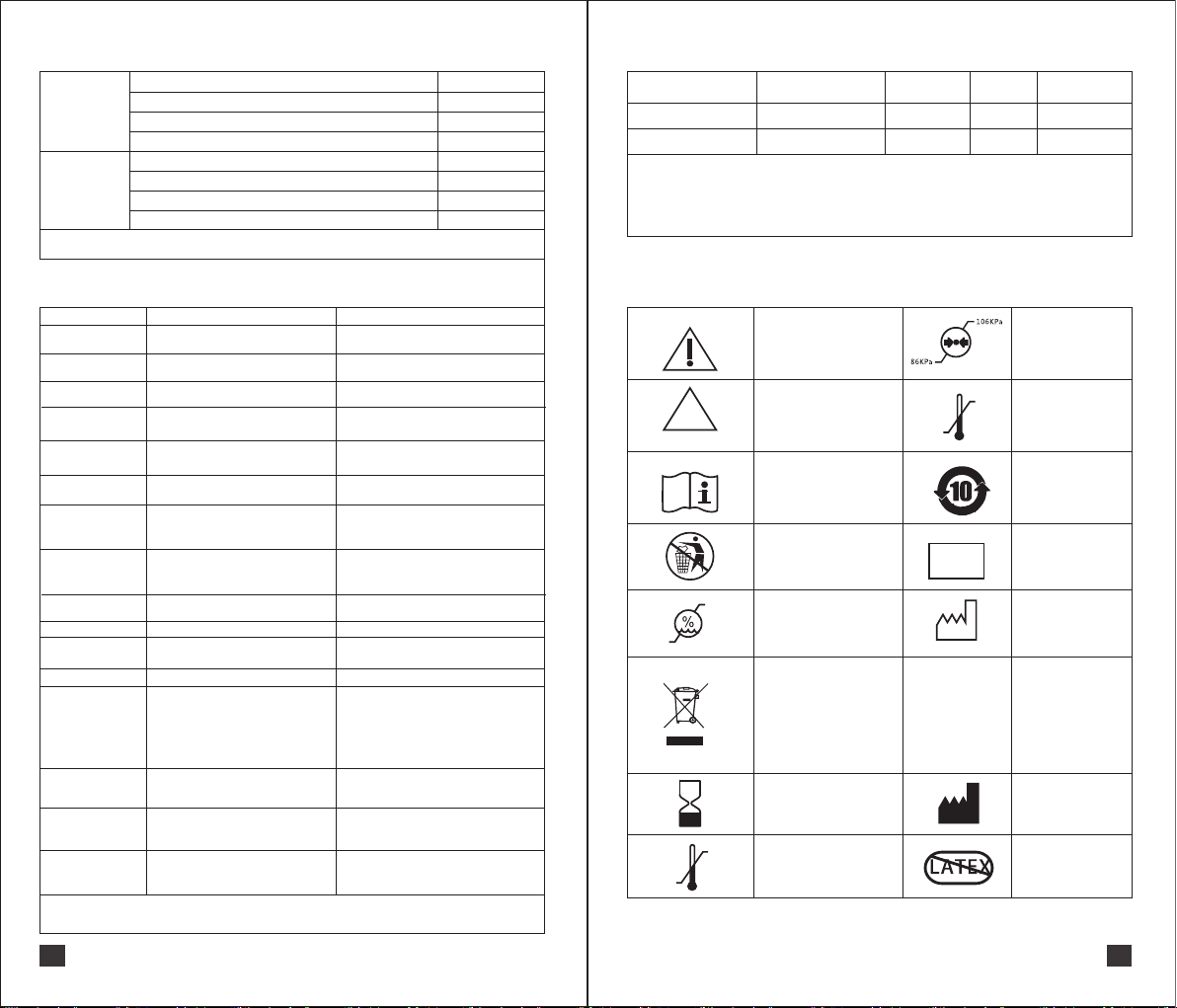
Appendix H: Hint sound characteristics
Sound pressure
Pulse sound
Pulse frequency
Number of harmonic components ±25db between 2KHZ and 4KHZ
Pulse duration
Sound pressure
Touch-tone
Pulse frequency
Number of harmonic components
Pulse duration
Hint sound pressure measurement: the sound pressure meter and the alarm generating device are measured
at a distance of about 1 m in the same plane.
About 50db~62db
1000 Hz
Not less than 1 piece
Not less than 100ms
About 50db~62db
About 938Hz,1.2kHz
No requirement
Not less than 80ms
Appendix S: List of accessories
Accessory
name
Pulse oximetry sensor
TYPEC
Warming:
Please use the specified accessories. Using other accessories may cause damage to animals or monitors.
Disposable accessories can only be used once, and repeated use may result in reduced performance or
cross-contamination. Do not use the accessory if it or it’s package is found to be damaged.
Operating period environmental requirements, etc.: please check attached manual
Accessory
specification
Tongue clip probe
Type-C Charging Cable
Accessory
model
603545123
DS-SMB-001
Using
range
Animal
Measuring
Earlobe, tongue
part
Appendix P: fault resolution
phenomenon possible reason Solution
Unable to boot
No pulse sound and
button sound
No alarm
Invalid button Internal cause
No data after
Bluetooth connection
No data on the
serial port
Probe
unconnected
Finding pulse
Probe off
Probe failure
Unnormal Pulseless
Overcurrent
Low perfusion
Blood oxygen values
don’t match clinical
estimates
Unnormal SpO2
No SpO2
Note: If the above method still cannot be measured normally, please call the after-sales
service line 400 058 0755 for consultation.
Battery is too low
Volume is 0 or the speaker is faulty
Alarm pause, alarm shutdown or horn failure
Communication code error
Communication code error
Probe and device are not connected firmly
Pulse is being searched
Probe off
Probe may be damaged Please replace the probe
Pulse undetected or probe may be damaged
Probe may be damaged Please replace the pulse
The probe type is not matched, the
measurement site is low in perfusion, the
probe is too tight, the hypothermia causes
capillary contraction, hypovolemia,
peripheral vascular disease or anemia, and
the probe is damaged
Low perfusion, the measuring position of
the probe is not suitable
Low perfusion index,
Inappropriate probe size,
Inappropriate measurement position
Probe that does not match the device
Inappropriate probe size
The lighting of the environment is too strong
Connect the base or charge the device through
TYPEC cable
Please check if the set volume is level 0
Please check if the alarm tone is off
Press multiple times, if it is still invalid, then
contact customer service
Please check if the communication mode of the
setting interface is Bluetooth communication
Please check whether the communication mode
of the setting interface is serial communication
Make sure the probe and device are securely
connected and the probe LED will flash. If the
probe LED does not flash, use another probe
If the "Finding Pulse" is displayed continuously
for more than 60 seconds, measure another
part quietly
Please check if the measuring part of
the probe is off
Please replace the measuring part or
replace the pulse
Choose the right probe for your animal,
Please ensure that blood flow is not restricted
and the probe should not be too tight
ensure temperature of animal/measurement
body is not too low
Replace the measurement site, etc
Check if the probe is too tight,
Change measurement position
Choose position with higher degree of perfusion,
Recommended blood laboratory test comparison
Choose the right probe
Choose the right probe for your animal, the
effect of shield the effect on the probe caused
by Ambient lighting
Appendix R: Symbols and signs
warming
Unsterilized Packaging
Please refer to the
instruction manual
This product can
be reused
80%
Working transport
storage environment
humidity
This symbol indicates that
electrical and electronic
equipment waste cannot be
disposed of as unsorted municipal
waste and must be recycled
separately. Dispose of in
accordance with the hospital
waste recycling regulations.
Period of use
55℃
Transport storage
environment temperature
0%
-10℃
NON
ST E RI LE
40℃
5℃
SN
INPUT:
5VDC-1A
Use and transport s
torage atmospheric
pressure limits
Working temperature
electronic product
Environmental
protection period
Serial number
Production Date
Input: DC 5V1A
manufacturer
No including emulsion
17
18
Page 12

11 Maintenance and cleaning
11.1 overview
Please keep your device and its accessories free of dust. To prevent damage of the equipment,
please obey the following strictly:
(1)Dilute the cleaner and disinfectant according to the manufacturer's instructions, or use
concentration as low as possible.
(2)Do not submerge the device in liquid
(3)Do not pour liquid onto equipment or accessories
(4)Do not allow liquid to enter the casing
(5)Do not use abrasive materials (such as steel wool or silver polish), and any strong solvents
(such as acetone or detergents containing acetone)
Warning
11.2 Cleaning and maintenance of blood oxygen meter
(1)Patient monitor can be cleaned by the most common hospital cleaning fluids and
non-corrosive detergents, but please note that many detergents must be diluted before they
used.
(2)Please follow the instructions of the detergent manufacturer.
(3)Avoid using ethanol-based, amino or acetone-based cleaners
(4)The monitor's case and screen should be kept free from dust and can be wiped with a soft,
lint-free cloth or a sponge dampened with detergent.
(5)Be careful not to pour liquid on the instrument during cleaning. Make sure that no liquid enters
the inside of the instrument.
(6)There are various types of cable sockets on the side panel of the monitor. Be careful when
wiping to ensure that no water can enter.
(7)Abrasive materials such as wire brushes or metal polishes are not permitted because they can
cause damage to the monitor panel and screen.
(8)Do not immerse the monitor in liquid.
(9)If you do not use it for a long time, Please take out the lithium battery from the device if it
unused for a long time..
(10)Maintenance once a year, please properly maintain this product to ensure normal use.
Warming: Remember to turn off the power and disconnect the power cord from
the outlet before cleaning the device or accessories.
Note: If you accidentally pour liquid onto the device or accessory, please contact
Maintenance or manufacturer immediately.
only if the hospital regulations you follow are deemed necessary.
Disinfection operations can cause a degree of damage to the monitor. It is recommended that
disinfection be operated that only cancel if it is deemed necessary in your hospital maintenance
plan.
Poison operation. Clean the equipment before disinfection.
Warming: Do not use ethylene oxide gas (ethylene oxide) or formaldehyde
for disinfection.
Note: The electrical schematic and component list are only provided for
qualified repair stations or personnel approved by the manufacturer.
Warning
11.4 Precautions
(1)Please follow local laws and regulations when you disposal instruments (including disposable,
recyclable) and batteries.
(2)Portable radio communication equipment may affect electronic medical equipment.
(3)The instrument should not be placed close to or stacked with other equipment.
(4)Please disassemble, install, or repair the equipment without authorization.
(5)If the instrument is to be connected to other equipment, please ensure that the external
equipment complies with IEC60601-1.
(6)If the red light in the blood oxygen sensor is dirty, it will affect the accuracy of the probe
measurement. So please make sure the probe is clean.
(7)For the regular maintenance of the instrument, please refer to <<Maintenance and
Cleaning>> in the manual.
(8)The waveform of the instrument has been normalized.
(9)There is no Tnatural latex for he material used to make the instrument
(10)Keep animals quiet before the instrument used
(11)A weak pulse or perfusion will affect the measurement.
(12)If the blood oxygen sensor is disposable , please do not reuse it.
(13)To avoid damage for the instrument, please remove the blood oxygen sensor first before
cleaning it.
(14)To avoid electrical hazards, please do not immerse the instrument in any liquid or clean it
with detergent. Please remove the battery first when cleaning the instrument.
(15)If the surface of the instrument is inadvertently wet during use, stop using it immediately.
When using it again, please make sure that the instrument and other accessories are dry. If
necessary, please contact your local distributor.
11.3 Cleaning and disinfection of accessories
Recommended disinfectant: 70% isopropanol solution. A 10% bleach solution can be used if a
lower standard disinfection is required. Do not use undiluted bleach (5% to 5.25% sodium
hypochlorite) or other undesired disinfection solutions to avoid damage to the sensor. For
cleaning and disinfection methods, please refer to the method of cleaning and disinfecting ECG
cables.
Note:
(1)Do not use radiation or steam to disinfect the sensor.
(2)Do not immerse the sensor directly in the liquid.
(3)To avoid long-term damage to the sensor, it is recommended that the product be disinfected
19
12 Warranty
12.1 Maintenance method
(a)Maintenance time: from 9:00 to 17:30(working days)
(b)Service method: Our company provides hotline service, email service and parts replacement
service.
Parts replacement: During the warranty period, we will replace equipment parts for free.
Parts are maintenance resources, if not specified, the user needs to return it to our company.
(c)We will upgrade the software system for users for free.
20
Page 13

12.2 Exemptions and restrictions
(a) We are not responsible for any damage caused by force majeure. Such as fires, lightning,
floods, hurricanes, hail, earthquakes, house collapses, riots, aircraft and traffic accidents,
deliberate damage, lack of fuel and water, labor disputes, strikes and lockouts and so on.
(b) Non-service item
Related expenses and insurance costs caused by disassembly, refurbishment, reassembly and
movement of equipment or its components.
Instrument adjusted, installed and equipment parts replaced by third-party companies which are
not recommended by us .
Equipment damage and malfunction caused by the users or representatives who did not operate
instrument in accordance with the operating manual.
(c) For equipment failures caused by equipment installation or connection to external equipment,
such as printers, computers, network cables, etc.If these operation without our permission ,
maintenance fee will be charged.
(d) Limitation of liability
During the validity period of the maintenance contract, if the user replaces the parts produced by
other manufacturers without our permission, we have the right to terminate the contract.
12.3 Non-warranty principle
● There are dirt and non-original marks that cannot be removed on the device housing.
● The device and accessories are physically damaged.
● Residual liquid and other foreign matter are present on the equipment, which causes short
circuit and trouble of the power strip.
● All probes and accessories are consumer products, not for free
● Damage of the probe caused by mechanical force is not included in the free range.
● Difficulties in measurement or inaccurate data due to limited measurement principles.
● Equipment damage caused by non-original packaging during transportation.
● Equipment failure caused by disassembly of equipment by professional or authorized
personnel who are not belong to our company.
● Equipment failure caused by incorrect operation without carefully reading the user manual.
12.4 Special requirements for warranty time
● The warranty period of our equipment is set according to the electronic product after-sales
service standards stipulated by national laws.
● The warranty period is one year for mainframe and three months for all accessories.
● Due to the fast update of electronic products, if the warranty time required by the user exceeds
the regulations, we will consider it as appropriate.
● For users who require more than three years warranty, we will not resell equipment parts to
them during the warranty period.
● We will upgrade the equipment or update the maintenance method, and the minimum price of
the new equipment will be charged if it is approved by the customer.
14 About after sales
14.1 Product registration / after sales information
Production date: shown as label
Manufacturer: Shenzhen Meid-link Electronics Tech Co., Ltd.
Address: Building A, Ying Tailong Ind Park, Dalang South Road, Dalang Street,
Longhua, Shenzhen, China, 518109
Hotline: 400-058-0755 Fax: +86 755 61120055
E-mail: [email protected] Website: www.medxing.com
14.2 open box to check
Remove the probe oximeter from the box and check if the shipping label is damaged, then check
that if all parts are complete according to the packing list.Please save the invoice, the bill of the
goods and all the packaging information. These can be used as a basis for negotiations with the
shipping company due to incomplete or damaged goods.If any parts are missing or damaged,
please contact our technical service department immediately.
Contact us:
Tel :+86 755 61120085
Fax:+86 755 61120055
E-mail:[email protected]
14.3 Packaged goods
Description
Veterinary palm pulse oximeter (host device)
Pulse oximetry sensor tongue clamp
user's manual
Type-C Charging Cable
Quantity
1 piece
1 piece
1 piece
1 piece
13 Repackaging
● Remove all accessories and put them in a plastic sleeve.
● Try to use the original box and packaging materials. During the transportation process, the
damage caused by improper packaging is borne by the user.
● If during the warranty period, please provide a copy of the relevant warranty card and invoice.
● Please describe the fault phenomenon in detail and provide the equipment at the same time.
21
22
Page 14
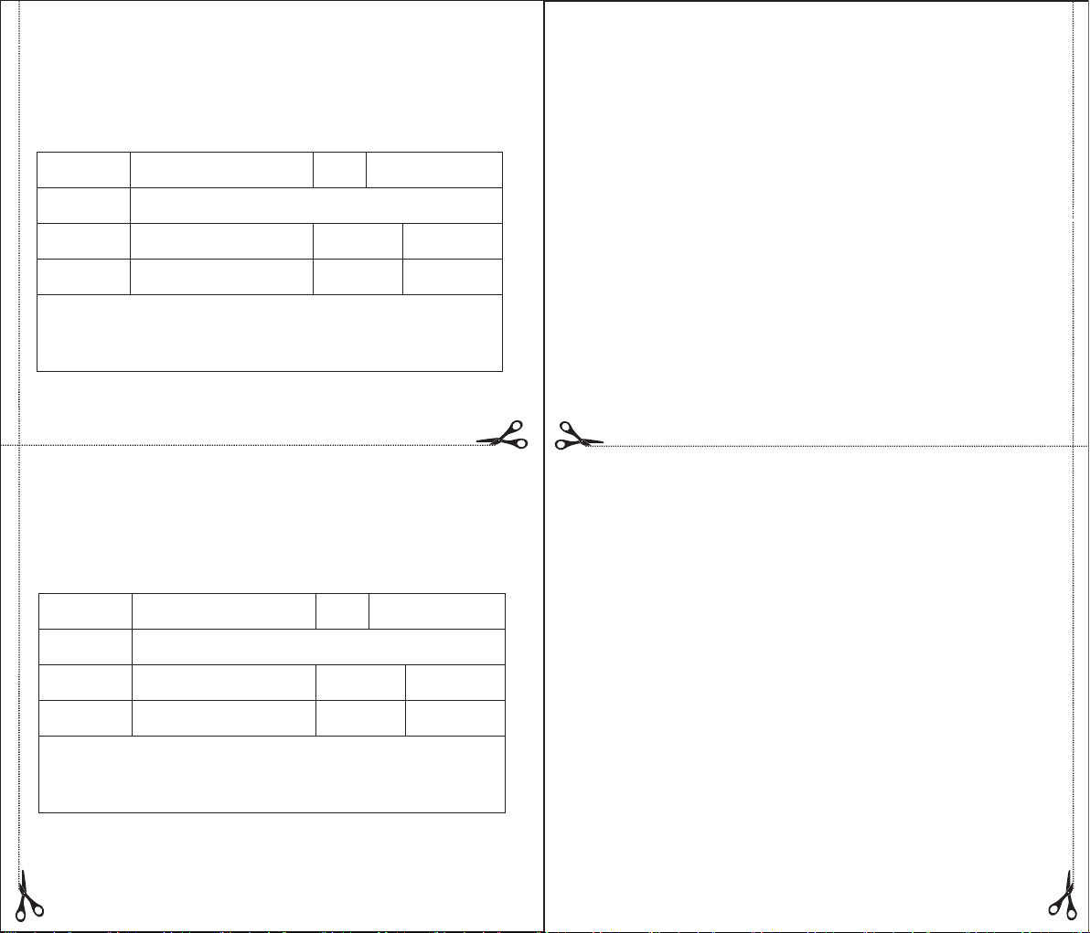
Product maintenance card
Warranty Regulation
(This joint is reserved for customers, with this card repair and return)
Customer
name
Tel.
Address
Product
Name
Purchase
Date
Product
REF NO.
City of
Purchase
Failure Description:
Product maintenance card
(This joint is reserved for customers, with this card repair and return)
Customer
name
Address
Product
Name
Purchase
Date
Failure Description:
Tel.
Product
REF NO.
City of
Purchase
1. Warranty period: within 1 year from the date of invoicing.
2. According to the use of the instructions and notices, the failure of the warranty period should be
repaired free of charge.
3. When you need to repair it for free, please carry and show the product maintenance card and
purchase invoice to the service agent.
4. The failure of this product during the warranty period should be accepted by the regional service
center or maintenance station of the company.
5. During the warranty period, the following conditions do not enjoy free repair:
● Failure and damage caused by improper or self-disassembly of the user.
● Due to improper storage, such as transportation failure, collision, battery leakage and other causes
of failure and damage.
● Damage caused by an irresistible force (e.g. earthquake fire, flood, lightning strike, etc.).
● Failure and damage caused by a place other than the use manual of this product.
● Without permission to alter this product maintenance card or invoice, the warranty is invalid.
● This product maintenance card acknowledges other circumstances
6. This product maintenance card is only valid in China, one card, no replacement.
7. The accuracy of this product is medical standard. To ensure the accuracy of your use, after the
warranty period, the company promises to continue to provide lifelong maintenance services such as
quality paid service and technical support.
Warranty Regulation
1. Warranty period: within 1 year from the date of invoicing.
2. According to the use of the instructions and notices, the failure of the warranty period should be
repaired free of charge.
3. When you need to repair it for free, please carry and show the product maintenance card and
purchase invoice to the service agent.
4. The failure of this product during the warranty period should be accepted by the regional service
center or maintenance station of the company.
5. During the warranty period, the following conditions do not enjoy free repair:
● Failure and damage caused by improper or self-disassembly of the user.
● Due to improper storage, such as transportation failure, collision, battery leakage and other causes
of failure and damage.
● Damage caused by an irresistible force (e.g. earthquake fire, flood, lightning strike, etc.).
● Failure and damage caused by a place other than the use manual of this product.
● Without permission to alter this product maintenance card or invoice, the warranty is invalid.
● This product maintenance card acknowledges other circumstances
6. This product maintenance card is only valid in China, one card, no replacement.
7. The accuracy of this product is medical standard. To ensure the accuracy of your use, after the
warranty period, the company promises to continue to provide lifelong maintenance services such as
quality paid service and technical support.
 Loading...