

Page 1

Annual
For
use
with
78399-880
XXXXX-XXX
Prior
to
performing
e
If
e
If
disassembling
e
Carefully
e
Precautions
Personnel
disinfectants.
DSD-201
PM
kit
possible,
the
disinfectant
Disconnect
Ra
Attach
Begin
If
software
Press
8,
Press
Repeat
Press
Start
the
purge
read
0,
CANCEL
anton
Con
PM
P/N:
the
preventative
schedule
the
on
side
ENTER,
ENTER
steps 3 — 6 for
flush
of
the
should
should
this
is
not
the
machine:
the
disinfectant
restrictor
A.
Enter
version
18
to
deactivate
twice
cycle
flush
cycle.
through
be
wear
Instructions
maintenance:
service
dumped
adapter
5.07
ENTER
to
for
the
taken
the
so
that
prior
filters.
in
both
the
diagnostics
or
above,
and
then
all
components.
side
B.
Press
exit
Diagnostics.
both
stations,
procedure
to
prevent
appropriate
it
coincides
to
the
basins.
mode,
press
O,
7,
ENTER
14,
ENTER
then
prior
to
spillage
personal
DRAFT
with
PM,
purge
SETUP
ENTER.
press
performing
If
to
purge
when
CANCEL
of
disinfectant
protective
COPY
the
replacement
the
disinfectant
88,
ENTER,
lower
level,
the
disinfectant
complete
and
the
PM.
when
equipment
135 and
proceed
with
the
ENTER
performing
when
of
the
lines
ENTER
to
out
steps
key
during
disinfectant.
prior
to
step
5.
of
the
pumps.
for
side
the
the
PM.
handling
B.
air
Tools
NOTE:
to
the
e
e
e
e
e
e
Required:
This
is a comprehensive
specific
7/16
instructions
in
nut
9/64-inch
5/16
nut
driver
Small
Flat-bladed
Asetof
3/8
“Philips”
open
end
driver,
and
3/32-inch
wrench
for
open
screw
screw
or
list
of
the
PM
end
wrench
hex
keys
driver
drivers
socket
all
tools.
kit
purchased.
wrench
Not
all
or
socket
Page 1 of
PM
kits
wrench
32
require
all
the tools
listed.
Please
refer
Page 2
Annual
e
Valve
e
John
ο
Lint
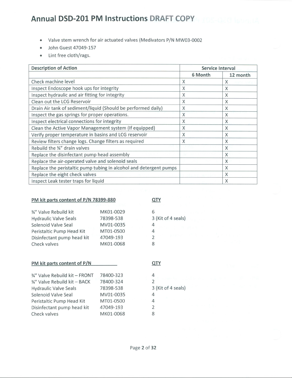
Description
Check
machine
Inspect
Inspect
Clean
out
Drain
Air
Inspect
Inspect
Clean
the
Verify
proper
Review
Rebuild
Replace
Replace
Replace
Replace
Inspect
Endoscope
hydraulic
the
tank
the
electrical
Active
filters
the
the
the
the
the
Leak
DSD-201
stem
wrench
Guest
47049-157
free
cloth/rags.
of
Action
level
hook
and
air
LCG
Reservoir
of
sediment/liquid
gas
springs
temperature
change
%” drain
disinfectant
air-operated
peristaltic
eight
tester
for
connections
Vapor
Management
logs.
valves
pump
check
traps
PM
for
ups
for
fitting
proper
for
in
basins
Change
pump
valve
tubing
valves
for
liquid
Instructions
air
actuated
integrity
for
integrity
(Should
operations.
integrity
and
filters
head
assembly
and
solenoid
in
be
system
LCG
as
alcohol
valves
performed
(If
reservoir
required
seals
(Medivators
equipped)
and
detergent
DRAFT
daily)
pumps
COPY
P/N
MW03-0002
Service
6
Month
X|x|xX|x|x|x|x|x|x|x
Interval
12
month
X|x|x|x|x|x|x|x|x|x|x|x|x|x|x|x
PM
kit
parts
%"
Valve
Rebuild
Hydraulic
Solenoid
Peristaltic
Disinfectant
Check
PM
%"
Valve
%"
Valve
Hydraulic
Solenoid
Peristaltic
Disinfectant
Check
valves
kit
valves
Valve
Valve
Pump
pump
parts
Rebuild
Rebuild
Valve
Valve
Pump
pump
content
kit
Seals
Seal
Head
head
content
kit—
kit — BACK
Seals
Seal
Head
head
of
P/N
Kit
kit
of
P/N
FRONT
Kit
kit
78399-880
MK01-0029
78398-538
MV01-0035
MT01-0500
47049-193
MK01-0068
78400-323
78400-324
78398-538
MV01-0035
MT01-0500
47049-193
MK01-0068
(Kit
of 4 seals)
A
(Kit
of 4 seals)
RUN
BP
EN
Page 2 of
32
Page 3
Annual
DSD-201
Preparation
Unplug
Close
the
If
equipped
Bleed
the
the
bleeder
1.
LEVELING:
The
disinfector
losses
of
fluids
floor, a unit
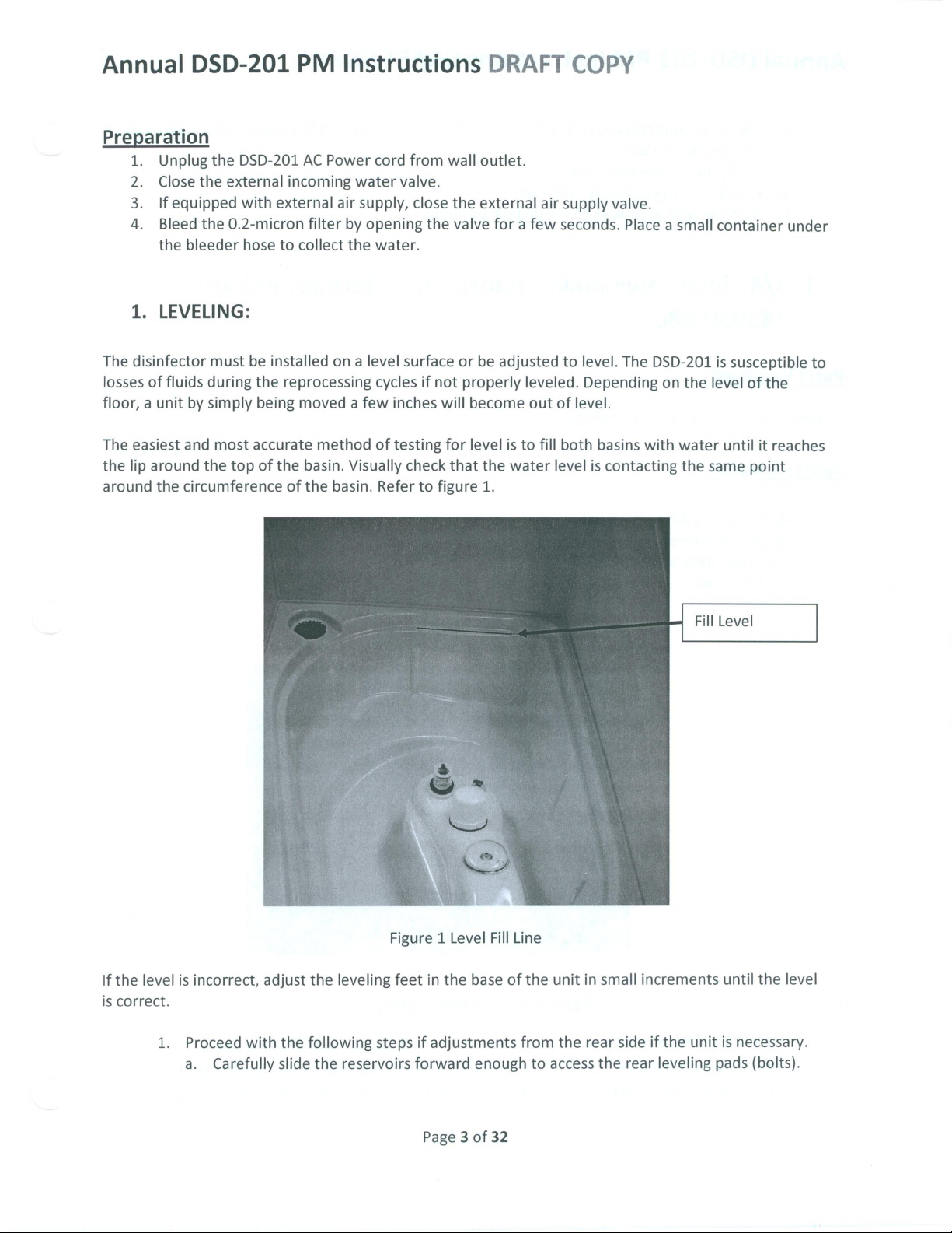
The
easiest
the
lip
around
by
and
around
the
circumference
the
DSD-201
external
with
0.2-micron
hose
must
be
during
simply
most
the
top
PM
AC
incoming
external
filter
to
collect
installed
the
reprocessing
being
moved a few
accurate
of
the
basin.
of
the
Instructions
Power
method
cord
water
valve.
air
supply,
by
opening
the
water.
on a level
cycles
inches
of
testing
Visually
basin.
Refer
from
close
surface
check
to
wall
the
if
not
will
for
figure
DRAFT
outlet.
the
external
valve
or
be
properly
become
level
that
the
1.
air
for a few
adjusted
leveled.
out
is
to
fill
water
COPY
supply
seconds.
to
level.
Depending
of
level.
both
basins
level
is
contacting
valve.
Place a small
The
DSD-201
on
with
water
the
the
level
same
container
is
susceptible
of
the
until
it
reaches
point
under
to
If
the
is
correct.
level
1.
is
incorrect,
Proceedwith
a.
Carefully
adjust
the
the
following
slide
leveling
the
reservoirs
Figure 1 Level
feet
in
the
steps
if
adjustments
forward
Fill
base
of
enough
Line
the
from
to
unit
in
the
rear
access
small
side
the
rear
Fill
increments
if
the
unit
leveling
Level
until
the
is
necessary.
pads
(bolts).
level
Page 3 of
32
Page 4
Annual
2.
δω
5.
1.
3/4
783990-880
DSD-201
Adjust
“A”
Verify
Ensure
Slide
and
the
the
the
“B”
that
disinfector
reservoirs
-inch
PM
appropriate
are
level.
is
the
reservoirs
back
valve
Instructions
leveling
level.
are
to
pads
clean.
the
original
until
the
positions.
maintenance
DRAFT
(Figure
COPY
1)
level
procedure
fill
lines
for
shows
PM
that
both
Kit
basin
Parts
%"
Drain
Tools
Required
valve
rebuild
Required
7/16-inch
Adjustable
Small
flat
Silicon
Grease
kit
nut
driver
wrench
blade
MKO1-0029
or
socket
or 1 1/8”
screw
driver
Qty
or
deep
6.
open
well
ended
socket
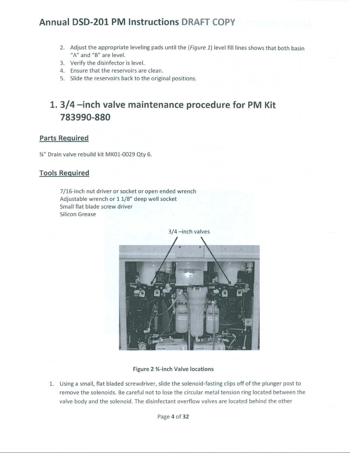
3/4
wrench
-inch
valves
1.
Using a small,
remove
valve
the
body
flat
bladed
solenoids.
and
the
solenoid.
Figure 2 %-inch
screwdriver,
Be
careful
not
The
disinfectant
Valve
slide
the
to
lose
the
Page 4 of
locations
solenoid-fasting
circular
overflow
32
metal
valves
clips
tension
are
located
off
ring
of
the
located
behind
plunger
between
the
other
post
to
the
Page 5
Annual
DSD-201
PM
Instructions
DRAFT
COPY
valves.
after
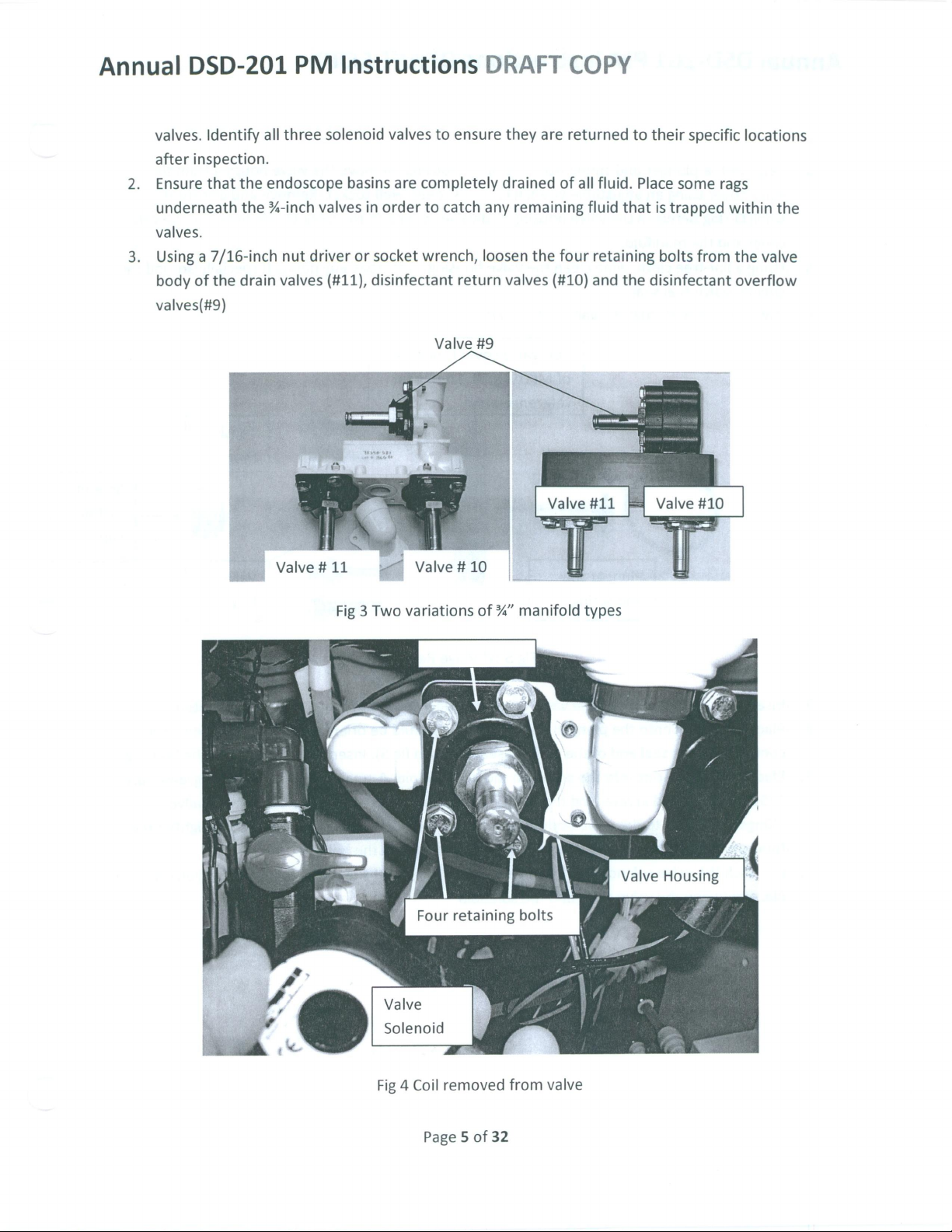
2.
Ensure
underneath
valves.
3.
Using a 7/16-inch
body
valves(#9)
Identify
inspection.
that
of
all
three
the
endoscope
the
%-inch
nut
the
drain
valves
Valve#11
solenoid
basins
valves
driver
(#11),
只
valves
are
in
order
or
socket
disinfectant
т
제
j=
Valve
to
ensure
completely
to
catch
any
wrench,
Valve
loosen
return
#9
#10
they
are
drained
remaining
the
valves
(#10)
Valve
ET
returned
of
all
fluid.
fluid
four
retaining
and
#11
to
their
Place
that
is
trapped
bolts
the
disinfectant
Valve
specific
some
rags
from
#10
locations
within
the
the
valve
overflow
Fig 3 Two
Valve
Solenoid
variations
of
%”
manifold
types
Fig 4 Coil
Page 5 of
removed
32
from
valve
Page 6
Annual
4.
Remove
valve
small
cover
5.
Using a lint-free
circular
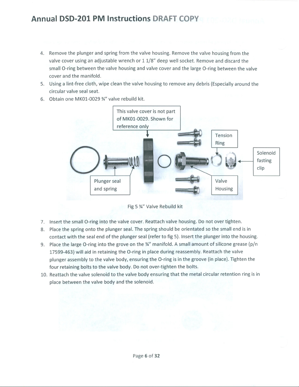
6.
Obtain
DSD-201
the
plunger
cover
using
O-ring
and
valve
one
between
the
manifold.
seal
MK01-0029
PM
and
an
adjustable
the
cloth,
wipe
seat.
Plunger
and
Instructions
spring
from
the
wrench
valve
housing
clean
%”
valve
This
of
reference
seal
spring
or 1 1/8”
and
the
valve
rebuild
MK01-0029.
kit.
valve
valve
valve
housing
cover
only
DRAFT
housing.
deep
cover
is
not
Shown
well
to
remove
part
for
COPY
Remove
socket.
and
the
the
large
any
valve
Remove
O-ring
debris
housing
(Especially
Tension
(
Valve
and
discard
between
Ring
|
)
而
に
Housing
from
the
around
A
を
the
the
valve
一
the
Solenoid
fasting
clip
7.
Insert
8.
Place
contact
9.
Place
17599-463)
plunger
four
10.
Reattach
place
the
small
the
spring
with
the
the
large
will
assembly
retaining
the
valve
between
O-ring
onto
seal
O-ring
aid
to
bolts
solenoid
the
valve
into
the
plunger
end
of
into
in
retaining
the
valve
to
the
valve
body
the
the
the
to
Fig 5 %”
valve
seal.
plunger
grove
the
O-ring
body,
body.
the
valve
and
the
Valve
cover.
on
ensuring
Reattach
The
spring
seal
the
%”
in
Do
not
body
solenoid.
Rebuild
should
(refer
to
manifold. A small
place
during
the
O-ring
over-tighten
ensuring
kit
valve
housing.
be
fig
5).
reassembly.
is
in
the
that
Do
orientated
Insert
the
amount
the
groove
bolts.
the
metal
not
over
so
the
small
plunger
of
silicone
Reattach
(in
place).
circular
retention
tighten.
end
into
the
grease
the
valve
Tighten
is
in
housing.
(p/n
the
ring
is
in
Page 6 of
32
Page 7
Annual
2.
3/4
783990-XXX
DSD-201
—inch
PM
valve
Instructions
maintenance
DRAFT
COPY
procedure
for
PM
Kit
Parts
Tools
Required
Required
Medium
#2
Phillips
___
Allen
____
Allen
flat
screw
blade
driver
screw
drive
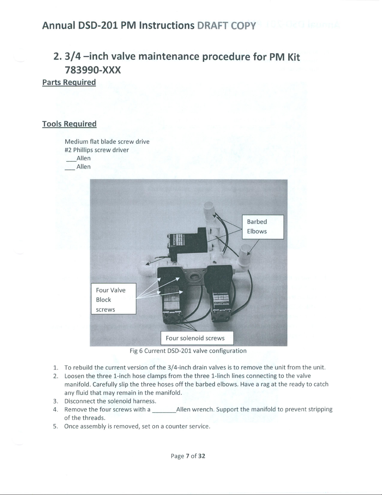
|
Barbed
Elbows
1.
To
2.
Loosen
manifold.
any
3.
Disconnect
4.
Remove
of
5.
Once
|
Four
Valve
|
Block
|
screws
rebuild
the
the
fluid
that
the
threads.
assembly
the
current
three
Carefully
may
the
solenoid
four
is
Fig 6 Current
version
1-inch
slip
the
remain
screws
removed,
hose
harness.
with
of
clamps
three
in
the
a
set
on a counter
Four
solenoid
DSD-201
the
3/4-inch
from
hoses
off
manifold.
Allen
Page 7 of
screws
valve
configuration
drain
valves
the
three
1-linch
the
barbed
wrench. Support
service.
32
elbows.
is
to
remove
lines
Have a rag
the
the
unit
connecting
at
manifold
from
to
the
the
to
prevent
the
valve
ready
unit.
to
catch
stripping
Page 8
Annual
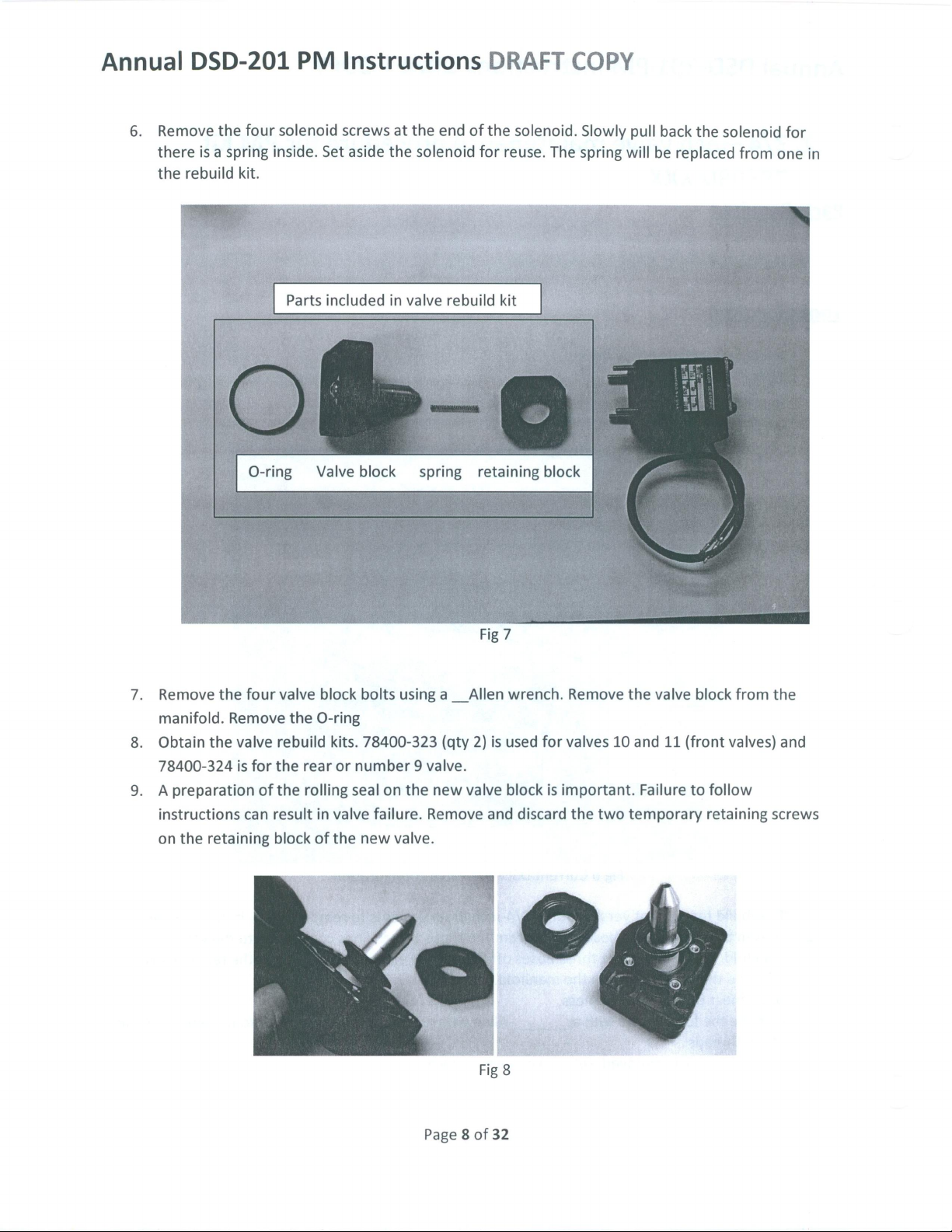
6.
Remove
there
the
DSD-201
the
four
is a spring
rebuild
kit.
PM
solenoid
inside.
Set
Parts
Instructions
screws
included
aside
at
the
the
solenoid
in
valve
end
of
rebuild
DRAFT
the
solenoid.
for
reuse.
kit
The
COPY
Slowly
spring
pull
will
back
be
replaced
the
solenoid
from
for
one
in
O-ring
7.
Remove
manifold.
8.
Obtain
78400-324
9. A preparation
instructions
on
the
the
retaining
the
four
Remove
valve
is
can
for
valve
the
rebuild
the
of
the
result
block
Valve
block
O-ring
kits.
rear
or
rolling
in
valve
of
the
block
bolts
78400-323
number 9 valve.
seal
new
spring
using
on
the
failure.
Remove
valve.
a__
(qty
new
retaining
Fig
7
Allen
wrench.
2)
is
used
valve block
and
discard
block
Remove
for
valves
is
important.
the
the
10
two
temporary
valve block
and
11
(front
Failure
from
valves)
to
follow
retaining
the
and
screws
Fig
8
Page 8 of
32
Page 9
Annual
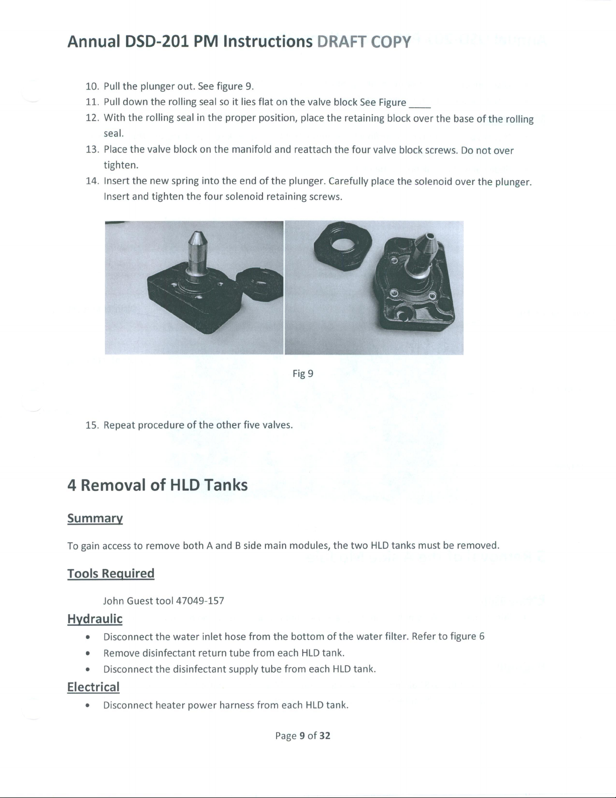
10.
Pull
11.
Pull
12.
With
seal.
13.
Place
tighten.
14.
Insert
Insert
DSD-201
the
plunger
down
the
rolling
the
rolling
the
valve
the
new
and tighten
PM
out.
See
seal
in
block
spring
the
Instructions
figure
9.
seal
so
it
lies
flat
the
on
the
into
four
proper
the
solenoid
position,
manifold
end
of
on the
and
the
retaining
valve
place
reattach
plunger.
DRAFT
block
the
the
Carefully
screws.
COPY
See
Figure
retaining
four
valve
place
|
block
block
the
over
the
screws.
solenoid
base
Do
over
of
the
not
over
the
plunger.
rolling
15.
Repeat
4
Removal
Summary
To
gain
access
Tools
Hydraulic
Required
John
e
Disconnect
e
Remove
e
Disconnect
procedure
of
to
remove
Guest
tool
the
disinfectant
the
of
the
other
HLD
water
disinfectant
Tanks
both A and B side
47049-157
inlet
hose
return
tube
supply
five
from
from
valves.
main
modules,
the
each
tube
from
Fig
9
bottom
HLD
each
the
of
the
tank.
HLD
two
water
tank.
HLD
filter.
tanks
must
Refer
be
to
figure
removed.
6
Electrical
e
Disconnect
heater
power
harness
from
each
HLD
Page 9 of
tank.
32
Page 10
Annual
e
Disconnect
e
Disconnect
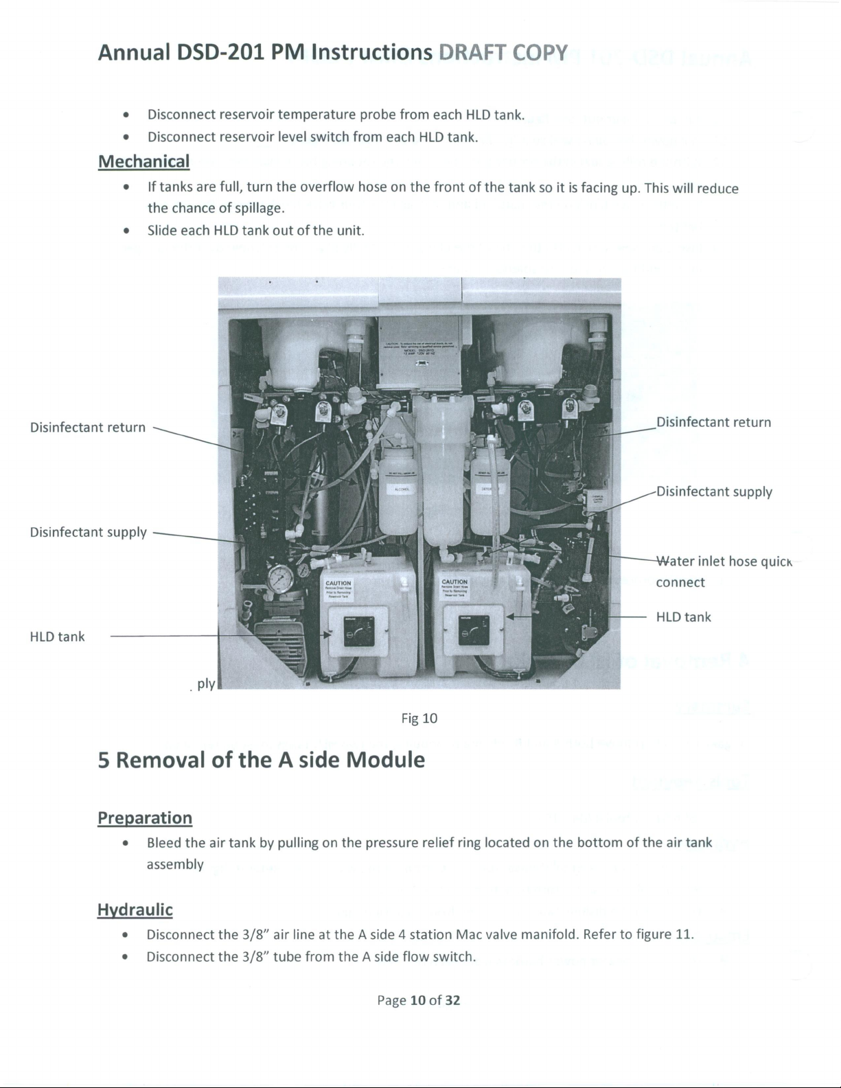
Mechanical
ο
If
tanks
the
e
Slide
DSD-201
reservoir
reservoir
are
full,
chance
each
of
HLD
PM
temperature
level
turn
the
spillage.
tank
out
Instructions
probe
switch
overflow
of
the
from
hose
unit.
each
on
from
HLD
the
DRAFT
each
tank.
front
ο
νο
HLD
of
tank.
the
ο.
COPY
tank
so
it
is
facing
up.
This
will
reduce
Disinfectant
Disinfectant
HLD
tank
return
supply
5
Preparation
Removal
of
the A side
Module
Fig
10
inlet
return
supply
hose
Disinfectant
Disinfectant
Water
connect
HLD
tank
quick
e
Bleed
assembly
Hydraulic
e
Disconnect
e
Disconnect
the
air
the
the
tank
3/8”
3/8”
by
pulling
air
tube
on
the
pressure
line
at
the A side 4 station
from
the A side
Page
relief
flow
10
ring
Mac
switch.
of
32
located
valve
manifold.
on
the
bottom
Refer
of
to
figure
the
air
11.
tank
Page 11

Annual
DSD-201
PM
Instructions
DRAFT
COPY
Disconnect
Disconnect
Disconnect
reservoir
Disconnect
valve
manifold
reassembly
Electrical
Disconnect
Disconnect
Disconnect
Disconnect
Disconnect
compressor
Disconnect
Disconnect
the
3/8”
tube
at
the
3/8”
tube
at
the
check
valve
side
of
the
break.
the
check
valve
side
of
the
break.
process.
the A side
the A side 4 station
the A side
the A side
the
and
the A side
the A side
flow
alcohol/detergent
compressor
spade
connector
the
air
tank.
disinfection
drain
switch
the
water
the
chamber
of
the A side
Refer
to
of
the A side
Separating
electrical
Mac
connector
located
pump
valve
connections.
valve
valve
alcohol
figure
detergent
valve
connector.
on
connector
inlet
if A side
inlet
line,
11.
the
two
connector.
manifold
the
black
valve
of A side
leaving
line,
check
connector.
wire
the
leaving
valves
Refer
to
that
manifold.
manifold.
check
valve
the
check
in
this
figure
7.
runs
between
with
valve
manner
the A side
the
with
will
alcohol
the A side
simplify
the
Main
4-station
Alcohol
Air
tank
Mechanical
Remove
Slide
valve
manifold
Mac
Valve
Flow
switch
and
detergent
check
valves
pressure
relief
pull
the
the A side
ring
three
module
bolts
that
out
secure
of
the
the A side
unit.
main
Fig
11
module
to
the
unit.
¡ue
Flow
switch
electrical
connection
Disinfection
(behind
compressor)
Compressor
pump
Page
11
of
32
Page 12

Annual
6.
Preparation
Hydraulic
DSD-201
Removal
Due
to
space
at
the
same
time,
proceeded
remove
PM
of
the B side
limitations
time.
to
the B side
Instructions
Module
at
many
facilities,
If
space
limitations
the
next
section
module
DRAFT
it
dictate
and
return
may
the
not
need
to
these
COPY
be
possible
to
work
instructions
on
to
one
remove
side
when
both
module
ready
sides
at
a
to
Disconnect
12.
Disconnect
Disconnect
Disconnect
Disconnect
alcohol
Disconnect
B
side
will
Electrical
Disconnect
Disconnect
Disconnect
Disconnect
Disconnect
Disconnect
the
the
the
the
the
reservoir
the
valve
simplify
the B side
the B side
the B side
the B side
the B side
the B side
3/8”
air
3/8”
tube
3/8”
tube
3/8”
tube
check
side
check
manifold
the
reassembly
line
at
the B side 6 station
from
the B side
at
the
water
at
the
chamber
valve
of
the B side
of
the
break.
valve
of
the B side
side
of
the
break.
process.
flow
switch
6-station
alcohol/detergent
compressor
chemical
disinfectant
Disconnect
electrical
Mac
valve
connector.
load
switch.
pump
flow
switch.
valve
inlet
valve
inlet
alcohol
detergent
Separating
connector.
manifold
connector.
connector.
Mac
valve
of
the B side
of
the B side
line,
leaving
line,
the
two
the
3/8”
Refer
connector.
manifold.
valve
the
leaving
check
tube
at
to
manifold.
manifold.
check
the
check
valves
the
main
figure
Refer
valve
in
12.
to
with
valve
this
water
Figure
the
with
the
manner
valve.
Mechanical
Remove
Slide
the
three
the B side
bolts
module
that
out
secure
of
the
Page
the B side
unit.
12
of
32
main
module
to
the
unit.
Page 13

Annual
DSD-201
PM
Instructions
DRAFT
COPY
Flow
switch
connection
electrical
7.
Valve
Parts
Seal
required
Replacement
Fig
12
6-station
(behind
manifold)
Main
Flow
Alcohol
check
Compressor
Disinfectant
Mac
main
Manifold
Switch
and
valves
Detergent
pump
valve
valve
Replacement
DSD-201
required 4 kits.
Tools
Allen
wrench
Allen
wrench
Valve
stem
John
Guest
Small
vise
Procedure
e
Lay
e
Note
valve
without
Required
9/64”
3/32”
wrench
Tool
grips
the
main
or
label
seal
kit
(4
re-circulation
MW03-0002
47049-157
or
small
channel
module
the
air
back
hose
seals,
option,
lock
on
the
that
connect
screws
and
requires 3 kits,
pliers
work
surface
the
loctite
Mac
valve
per
pack)
DSD-201
to
with
the
pneumatic
re-circulation
block
valves.
option
Page
13
of
32
Page 14

Annual
DSD-201
e
Usinga___
manifold.
e
Set
the
e
Pull
the
e
Use
the
loosen
release,
a
vice
screw
e
Ensure
mounting
e
Assemble
assemble
e
Tighten
16.
e
Reattach
with
your
deformation.
e
Repeat
station
PM
Instructions
Allen
Refer
valve
old
valve
the
retaining
do
grips
completely.
that the
area.
the
the
the
the
thumb,
the
above
water & disinfectant
to
on the
valve
seal
stem
not
attempted
pliers
and
valve
new
valve
valve
block
Do
not
wrench,
Figure
Refer
valve
seal
valve
tighten
procedure
work
surface
off
the
wrench
screw
unscrew.
to Fig
is
completely
seal
seal
to
retaining
to
the
over
13
tighten
remove
retaining
to
hold
in
the
center
to
remove
Once
15
apply
the
valve
screw
the
main
screws
for
each
valve.
DRAFT
the
four
so
the
valve
screw.
the
valve
of
with
released
clean;
one
drop
shaft.
until
manifold.
in a uniform
the
screws
valve
Refer
to
COPY
screws
the
the
remove
the
on
figure
holding
seal
is
facing
Refer
to
shaft
and
valve
seal.
wrench.
use the
any
of
Loctite
seal
deforms
While
diagonal
retaining
the A and B main
17.
the
up.
fig
14
using
the
If
the
Grip
the
3/32”
Allen
traces
of
to
the
screw
the
pressing
manner
screws.
top
valve
3/32”
screw
edges
wrench
Loctite
threads
shape.
down
to
manifold
to
the
Allen
does
not
of
the
to
from
Refer
on
the
minimize
and
main
wrench,
easily
screw
with
remove
the
and
to
block valve
the
the
screw
re-
Figure
the
side
B
Page
14
of
32
Page 15

Annual
DSD-201
PM
Instructions
DRAFT
Fig
14
COPY
Page
Fig
15
of
15
32
Page 16

Annual
DSD-201
PM
Instructions
DRAFT
COPY
Fig
17
“B"
Station
ASM1-0086
LOT#144581
Water & Disinfectant
Page
16
REV.D
of
32
manifold
Page 17

Annual
8.
DSD-201
Check
Each
DSD-201
the
B
station
a
check
valve
PM
valve
has
three
water
and
and
two
Instructions
replacement
check
valves
disinfectant
sealing
O-rings.
located
valves.
DRAFT
in
both
Each
check
COPY
the A and B main
valve
kit
MKO1-0068
manifold
is
comprised
and
two
in
of
Parts
Required
MK01-0068
DSD-201
Tools
Silicon
with
Allen
Grease
wrench
Procedure:
e
e
e
e
Qty
8
recirculation
With
the
main
retaining
Once
back
all
and
screws
four
forth
manifold.
With
the
block
imperative
Remove
both
holes
ends
on
the
both
requires
module
with a _Allen
retaining
gently
removed,
the
new
check
to
the
the
check
valve
check
check
12
on
lying
screws
to
release
note
valves
from
valve.
valve
check
on a table,
wrench.
are
the
the
be
the
The
block
valves.
remove
Refer
removed,
block
with
orientation
reinserted
check
valve
O-ring
and
may
the
to
figure
gently
the
of
the
in
the
block.
be
found
main
manifold.
the
four
18
rock
check
check
same
Remove
in
check
the
check
valves
valves.
direction.
the
both
the
valve
block
valve block
from
the
It
is
O-ring
from
check
main
valve
Page
17
of
32
Page 18

Annual
DSD-201
PM
Instructions
DRAFT
COPY
Fig
18
Fig
19
Page
18
of
32
Page 19

Annual
DSD-201
PM
Instructions
DRAFT
Fig
20
COPY
e
Insert
manifold.
valve
e
Insert
to
the
four
e
Repeat
manifold.
9.
Alcohol
Tools:
Small
Philips
Adjustable
Procedure:
e
wrench
Remove
coil,
21.
Retain
the
to
ease
the
main
screws
the
head
make
Older
this
new
O-rings
Coating
into
check
valves
manifold.
in a uniform
procedure
and
screw
the
large
note
of
DSD-201’s
spacer
into
check
the
the
O-ring
block
easier.
into
the
Insert
manner.
for
both
with a small
check
the
four
main
Detergent
driver
nut
on
top
of
the
the
position
will
for
reassembly.
of
have a spacer
valve
retaining
amount
valve
check
module
valve
alcohol and
the
coil.
washer
hole
of
block,
verifying
valve block
and
the
seal
detergent
Remove
the
located
and
the
hole
on
the
silicon
grease
the
retaining
“B”
station
will
allow
proper
direction.
screws
water & disinfectant
replacement
valves.
coil
by
between
Before
pulling
the
up.
coil
main
the
and
tighten
removing
Refer
to
and
valve
check
Attach
the
the
Figure
body.
Page
19
of
32
Page 20

Annual
DSD-201
e
Remove
Refer
to
e
Pull
the
press
back
e
Note:
lever;
e © Reattach
Each
this
PM
the
four
Figure
old
valve
onto
alcohol
will
the
valve
Instructions
Phillip
head
22.
seal
off
the
the
valve.
Refer
and
detergent
cause
the
valve
body
and
attach
screws
plunger
to
figure
valves
to
stay
the
DRAFT
from
the
valve
of
the valve.
23.
has a red
permanently
coil
and
COPY
and
lift
Obtain a mew
lever
on
open.
coil
retaining
the
valve
one
side.
screws.
off
valve
Do
the
manifold.
MV01-0035
not
rotate
and
the
Fig
Page
20
21
of
32
Page 21

Annual
DSD-201
PM
Instructions
Fig
DRAFT
22
COPY
10.
Disinfectant
Pump
Head
Page
21
replacement
of
32
Page 22

Annual
DSD-201
PM
Instructions
DRAFT
COPY
Tools
Large
John
Adjustable
required:
Phillips
Guest
Procedure
e
e
screw
driver
tool
wrench
for
Side
Disconnect
John
Guest
hoses
and
Refer
to
figure
the
motor assembly
head).
fittings
new
Remove
on
pump
A:
the
tool.
pump
the
input
head.
hose
from
Have a rag
head.
24
and
remove
(retain
the
pump
and
Discard
the
top
or
small
the
these
head.
output
the
pump
and
container
three
screws
Using
of
the
head.
bottom
screws
for
attaching
an
adjustable
pump
head.
of
the
ready
that
These
pump
to
capture
secure
the
replacement
wrench,
will
head
liquid
the
pump
remove
be
utilizing
reused
from
head
pump
the
on
the
two
the
to
the
Page
22
of
32
Page 23

Annual
DSD-201
PM
Instructions
DRAFT
COPY
Remove
three
these
screws
Remove
save
two
and
these
fittings
e
e
e
Unpack
three
screws.
shaft
from
Once
the
motor.
Apply
removed
Reattach
Refer
three
the
new
the
screws
to
from
the
pump
Please
motor
are
to
Figure
four
the
inlet
and
head
note
is
on
tighten,
25.
wraps
old
head.
outlet
Page
and
the
connection
an
eccentric,
the
of
Teflon
Reattach
hoses
23
of
32
fit
to
pump
tape
to
Fig
24
the
on
and
head
to
these
the
motor
the
will
will
the
threads
fittings
pump
assembly
pump
head
appears
line
properly
of
to
the
head.
using
to
be
the
new
the
that
not
with
two
pump
original
mates
with
centered.
the
pump
connectors
head.
the
Page 24

Annual
DSD-201
PM
Instructions
DRAFT
COPY
View
of
the
pump
head
side
that
mates
with
motor.
This
part
an
eccentric
and
will
not
center.
normal
type
head
of
This
for
pump
is
on
this
the
on
is
Procedure
for
side
e
Disconnect
John
hoses
e
Refer
the
head).
fittings
pump
ο
Rotate
e
Rotate
There
that
from
Discard
e
Apply
to
the
B:
Guest
and
to
motor
Remove
on
head.
the
the
is a
must
the
the
three
the
top
fitting
pump
figure
assembly
the
threaded
be
bottom
(output)
if
the
hose
tool.
Have a rag
head.
24
and
the
pump
input
silver
handle
three
way
coupling
retained
of
the
pump
head.
or
four
wraps
side
necessary.
from
the
remove
(retain
head.
and
output
on
valve
for
use
pump
Refer
of
of
the
top
and
or
small
the
three
these
screws
Using
of
the
the
three
counter
between
on
the
head
to
figure
Teflon
pump
bottom
container
screws
for
attaching
an
adjustable
pump
head.
way
valve
clockwise
the
pump
new
pump
for
reuse
27.
tape
to
the
head.
Apply
of
the
ready
that
These
90
degrees.
off
the
head
head.
on
the
threaded
Teflon
pump
head
to
capture
secure
wrench,
replacement
the
replacement
will
top
of
and
the
Remove
coupling
tape
the
pump
remove
be
Refer
the
three
the
to
utilizing
liquid
from
head
pump
the
reused
to
figure
pump
head.
way
coupling
pump
and
insert
both
ends
the
the
to
two
on
new
26
valve
head.
of
in
Page
24
of
32
Page 25

Annual
Three
rotated
position
the
valve
off
the
way
90
that
pump
valve
degrees
will
to
be
head.
DSD-201
e
e
e
handle
into
a
allow
rotated
PM
Screw
valve
Apply
removed
Reattach
Instructions
the
three
way
handle
three
to
from
the
90
degrees
four
the
inlet
wraps
old
and
valve
back
head.
outlet
DRAFT
back
on
to
of
Teflon
Reattach
hoses
top
the
original
tape
to
COPY
of
the
to
these
the
pump.
pump
position.
the
threads
fittings
to
head.
of
the
Return
the
two
new
pump
the
silver
connectors
head.
11.
Peristaltic
Pump
Retain
for
Tube
this
reuse.
Fig
threaded
27
coupling
Replacement
Page
25
of
32
Page 26

Annual
DSD-201
These
instructions
tubes.
PM
Instructions
should
be
followed
to
replace
DRAFT
the
COPY
detergent
and
alcohol
peristaltic
pump
Parts
Tools
Required
MT01-0500
Required
Phillips
John
Guest
Procedure
Place a small
disconnecting,
of
the
pump
The
two
housing
right
of
the
“A”
tubing
reassembly,
Peristaltic
Screw
Tool
alcohol
which
and
just
side
one
pump
Driver
container
small
amounts
tube.
pumps
is
in
the
behind
of
the
machine
at a time
label
each
Tube
or
rags
are
center
the
to
tube
Set
under
of
detergent
located
of
the
0.2
micron
and
the
avoid
before
each
of
the
and
alcohol
to
the
left
of,
machine.
filter
bottom
confusion
disconnection.
The
housing.
pump
with
tubing
connections
will
and
just
detergent
The
supply
the
plumbing.
be
lost
behind
pumps
top
pumps
the
“B”
when
during
the
0.2
are
on
side.
To
assist
replacement
micron
located
both
Replace
filter
to
side
the
with
the
supply
e
Identify
servicing.
e
Identify
e
Remove
pulling
gently
released.
e
Remove
e
Position
egual
e
Position
e
Lay
place
e
Replaced
e
Re-connect
and
and
the
pulling
length.
the
new
until
disconnect
remove
cover
to
tube
the
the
new
the
new
the
pinch
tube
the
tube
the
cover
the
expose
out
tube,
tube
tube
rollers
in
is
using
inlet
the
inlet
four
screws
pump
of
the
support
keep
set
from
over
the
as
in
the
recess
completely
the
and
outlet
Page
26
and
outlet
from
tube.
Remove
recess,
rotating
the
packaging.
pump
figure
29
and
rotate
installed.
screws
of
that
tubes
32
pump
and
head
were
that
tubing
covers.
the
rotate
pulling
so
that the
the
roller
Refer
removed
were
disconnected
from
Refer
tubing
the
pinch
until
the
inlet
as
you
to
figure
the
pump
to
Figure
from
the
roller
tube
and
feed
30.
earlier.
during
you
are
28.
pump
by
hand
is
completely
outlet
are
the
tube
removal.
hear
while
of
into
by
Page 27

Annual
DSD-201
e
PM
Priming
Instructions
of
the
pumps
will
DRAFT
be
performed
COPY
in
Section
14.
Remove
screws
these
Fig
28
Page
27
of
32
Page 28

Annual
DSD-201
PM
Instructions
DRAFT
COPY
12.
Preparation
Verify
all
work
Mechanical
Slide
Install
Hydraulic
Connect
Connect
Connect
Connect
Connect
Connect
valve
Reinstallation
is
complete
the A side
the
three
the
the
the
the
the
the
manifold
module
bolts
3/8”
3/8”
tube
3/8”
tube
3/8”
tube
check
check
side
on A side
out
that
air
line
to
to
to
valve
valve
of
the
of A side
module
of
secure
to
the A side 4 station
the A side
the
water
the
chamber
of
the A side
of
the A side
break.
the
unit.
the A side
flow switch.
valve
prior
valve
alcohol
detergent
Fig
30
Module
to
reinstallation.
main
module
Mac
valve
Refer
inlet
to A side
inlet
of A
line.
Refer
line,
leaving
to
manifold.
to
figure
valve
side
manifold.
to
figure
the
unit.
31.
manifold.
31.
the
check
Refer
valve
to
figure
with
31.
the A side
Electrical
Connect
the A side
flow
switch
electrical
connector.
Page
28
of
32
Refer
to
figure
31.
Page 29

Annual
Main
e
e
e
e
ο
e
valve
DSD-201
Connect
Connect
Reconnect
Connect
compressor
Connect
Connect
manifold
PM
Instructions
the A side 4 station
the A side
the A side
the
and
the A side
the A side
alcohol/detergent
compressor
spade
connector
the
air
disinfection
drain
tank.
valve
Mac
valve
manifold
connector.
connector
located
connections.
pump
on
connector
the
ve
DRAFT
connector.
black
wire
that
COPY
runs
between
the A side
Flow
switch
electrical
connection
4-station
Alcohol
tank
Air
Mac
Flow
and
detergent
check
pressure
pull
13.
Mechanical
Hydraulic
Valve
switch
valves
relief
ring
e | Slide
e
e
e
e
ο
e
Reinstallation
the B side
Insert
and
Reconnect
32.
Connect
Connect
Connect
Connect
Connect
the
the
the
the
the
module
tighten
the
3/8”
3/8”
3/8”
3/8”
check
check
of B side
into
the
three
air
line
tube
to
tube
to
tube
to
valve
of
valve
of
the B side
the
the
Fig
31
Module
the
unit.
bolts
that
secure
at
the B side 6 station
flow
switch.
water
valve
inlet
chamber
the B side
the B side
valve
alcohol
detergent
the B side
Mac
Refer
of
the B side
inlet
of
the B side
line.
Refer
line.
main
valve
to
Figure
to
module
manifold.
32.
valve
manifold.
manifold.
Figure
32.
to
the
Refer
Disinfection
(behind
compressor)
Compressor
unit
to
Figure
pump
Page
29
of
32
Page 30

Annual
Electrical
DSD-201
e
Connect
e
Disconnect
e
Disconnect
e
Disconnect
e
Disconnect
e
Disconnect
e
Disconnect
PM
the
3/8”
the B side
the B side
the B side
the B side
the B side
the B side
Instructions
tube
at
the
main
water
flow
switch
6-station
alcohol/detergent
compressor
chemical
disinfectant
electrical
Mac
connector.
load
pump
DRAFT
valve.
valve
manifold
connector.
switch.
connector.
COPY
connector.
connector.
Refer
to
Refer
figure
to
figure
32.
32.
14.
Final
Procedure:
Plug
the
up
correctly
Station A and
illuminated.
e
e
checks.
DSD-201
Open
Place a restrictor
power
and
is
Station B yellow
the
incoming
in
an
cord
idle
adaptor
back
state.
LED
water
into
the
Note:
the
indicators
supply
into
Page
valve.
each
30
of
Fig
12
power
unit
above
basin.
32
outlet.
is
in
the
and
Ensure
idle
below
that
state
the
the
when
LCD
machine
the
display
are
powers
not
Page 31

Annual
A.
B.
C.
D.
E.
F.
DSD-201
e
Fill
PM
the
reservoirs
instructions.
The
next
steps
will
appropriate
Using
pump
the
pump
Activating
e
e
Activating
e
valve
diagnostics
until fluid
and
run
appears
close
Side A Alcohol
Select
Station
Enter
diagnostics
valve
by
pressing
ENTER.
the
Once
pump
Side A Detergent
While
still
Activate
the
(detergent
restrictor,
Activating
Activating
Side B Alcohol
e | Select
e
Enter
diagnostics
valve
by
ENTER.
the
pump
Side B Detergent
e
While
Activate
restrictor,
e
Press
14,
CACNEL
Station
pressing
Once
still
the
ENTER
twice.
Commence a cycle
set
up
and
diagnostics
e
Cycle
parameters
e
e
e
e
e
Sensors
Proper
No
No
The
are
operation
leaks
occur
leaks
occur
external
requirements,
e
The
alcohol and
e
The
basins
Instructions
with
the
be
performed
or
alcohol)
the
appropriate
from
the
the
valves.
A.
fluid
and
valve.
in
diagnostics
pump
turn
off
B.
fluid
and
valve.
in
diagnostics
pump
turn
off
to
on
both
menus.
set
and
during
during
water
(35-40
detergent
fill
to
the
Repeat
pump:
by
pressing
12,
ENTER,
is
seen
pump:
by
pressing
the
pump
pump:
by
pressing
12,
ENTER,
is
seen
pump:
by
pressing
the
pump
open
sides,
are
adjusted
working
of
the
cycle.
the
the
pressure
PSI).
appropriate
DRAFT
disinfectant
once
the
unit
for
pump
scope
hook
the
above
88,
ENTER.
18,
ENTER.
coming
press
coming
press
the B side
performing
disinfectant
rinse
solutions
out
1,
ENTER,
19,
ENTER.
and
valves
88,
ENTER.
18,
ENTER.
out
1,
ENTER,
19,
ENTER.
and
valves
main
to
appropriate
properly.
cycle.
during
the
level
using
is
the
side
to
prime
up
of
of
the
cycle.
flush
are
during
by
by
Input
Then
the
which
Input
Then
the
which
water
injected
COPY
setup
1.
completely
of
the
machine
the
system.
or
restrictor.
process
Once
Once
following.
for
code
turn
the
restrictor,
opens
detergent
pressing
0,
code
turn
the
restrictor,
opens
detergent
pressing
0,
valve.
Refer
settings.
mode
meets
as
desired.
the
disinfectant
Refer
to
the
reassembled.
you
Continue
Once
fully
the
three
remaining
135,
ENTER.
pump
on
press
0,
Enter
the
valve,
then
is
seen
ENTER.
135,
ENTER.
pump
on
press
0,
Enter
the
valve,
then
is
seen
ENTER.
Exit
diagnostics
to
the
the
installation
REFER
and
use
manual
Open
are
working
running
primed,
Open
the
by
entering
to
18,
flowing
Open
the
by
entering
to
18,
flowing
by
service
TO
SECTION
rinse
phases.
for
the
on.
the
turn
off
pumps.
alcohol
3,
deactivate
Enter.
from
the
alcohol
3,
deactivate
Enter.
from
the
pressing
manual
for
Page
31
of
32
Page 32

Annual
DSD-201
e
No
e
When
located
plugged
order
step
b.
Ensure
During
the
housing
d.
Check
using
SETUP,
e.
Clean
PM
excessive
the
on
into
to
re-apply
where
that
the
the
cycle,
using
the
accuracy
2,
any
fluid
Instructions
noise,
fumes
disinfectant
the
inside
it.
Wait
it
had
DSD
ensure
the
of
ENTER
or
residue
cycle
back
five
AC
power.
stopped.
completes
that
bleeder
the
LCG
(for
the
from
or
orders
begins,
wall
of
seconds,
The
DSD
one
full
there
are
valve.
display
date)
and
the
cabinet
DRAFT
are
noted.
press
the
the
cabinet
and
then
depress
should
disinfection
no
for
date
SETUP,
resume
leaks inside the
and
3,
assembly.
COPY
TEST
and
cycle
time.
ENTER
button
has the
the
RESET
the
without
unit
If
incorrect,
(for
on
the
GFI
outlet
printer
transformer
button
Disinfectant
any
and
alarms.
bleed
cycle
any
reset
time).
on
the
which
the
GFI
from
air
from
valves
is
in
the
Page
32
of
32
 Loading...