

Page 1
DSD-201,
DSD-201LT
Endoscope Reprocessor
Domestic, U.S. only
Illustrated Parts Guide
50096-127 Revision A
Page 2

This document is designed to provide a quick and easy reference to the major replacement parts and
components for the DSD-201. It does not include some of the smaller items such as screws and washers.
The electronic circuit boards are also listed in a table.
The parts listed in this document are subject to change without notice.
To order parts or place a Technical Service call, contact the Technical Assistance Center at 800-848-9024.
2004, Medivators Reprocessing Systems
DSD-201 Illustrated Parts Guide
Page 3

Contents
Page
Electronic Circuit Boards and Accessories . . . . . . . . . . . . . . . . . . . . . . 3
DSD Front View . . . . . . . . . . . . . . . . . . . . . . . . . . . . . . . . . . . . . . . . . 8
DSD Top View . . . . . . . . . . . . . . . . . . . . . . . . . . . . . . . . . . . . . . . . . . 9
Basin, Top View . . . . . . . . . . . . . . . . . . . . . . . . . . . . . . . . . . . . . . . . 10
Basin, View of Underside . . . . . . . . . . . . . . . . . . . . . . . . . . . . . . . . . 11
Station A Main Module Assembly . . . . . . . . . . . . . . . . . . . . . . . . . . . . 12
Station B Main Module Assembly . . . . . . . . . . . . . . . . . . . . . . . . . . . 13
Detail of Main 6 Valve Manifold . . . . . . . . . . . . . . . . . . . . . . . . . . . . . 14
Alcohol / Detergent and Internal Water Filter Assembly . . . . . . . . . . . 20
LCG Reservoir Assembly . . . . . . . . . . . . . . . . . . . . . . . . . . . . . . . . . 24
Air Tank . . . . . . . . . . . . . . . . . . . . . . . . . . . . . . . . . . . . . . . . . . . . . . 27
GFI . . . . . . . . . . . . . . . . . . . . . . . . . . . . . . . . . . . . . . . . . . . . . . . . . . 28
Filters and Accessories . . . . . . . . . . . . . . . . . . . . . . . . . . . . . . . . . . . 29
50096-127 Revision A
Page 4
2
DSD-201 Illustrated Parts Guide
Electronic Circuit Boards, Cables and Assemblies
Item Part Number
Pg PC Boards / Power Supplies
4 CPU with Temperature Monitor MB01-0016
6 Digital I/O MB01-0017
6 Sensor MB01-0018
6 Leak Tester (S.I.T.) MB01-0020
10 Control Panel MB01-0022
4 Valve Drive (110V) MB01-0019
4 5 VDC P.S. MS06-0003
4 24 VDC P.S. MS06-0005
Cables
6 Digital Output / Sheath / Sensor MC08-0051
7 Digital Output / Sensor MC08-0510
4 CPU / Valve / Do Ribbon MC08-0511
4 Valve Board Interconnect MC08-0512
5 Control Panel Bus Line MC08-0508
Fuses
Main Fuse
4 1-1/2 Amp MF02-0004
Valve Drive Board
5 3.15 Amp (Qty 2) MF02-0014
5 5 Amp MF02-0017
Air Tank Wiring Harness Fuse
5 6.25 Amp MF01-0018
Page 5
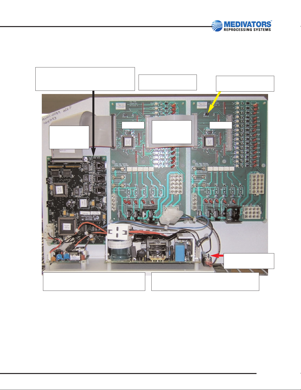
Main Electronic Panel Assembly: ASM1-0089
3
50096-127 Revision A
MC08-0512
Valve Board
Interconnect
A Side
B Side
MC08-0511
CPU to
Valve Board
MB01-0016
OPU Board (motherboard)
Shown w/Temp monitoring
5 VDC Power Supply MS06-0003
5 VDC Harness MH05-0011
24 VDC Power Supply MS06-0005
24 VDC Harness MH05-0053
1.5 Amp Fuse
MF02-0004
Valve Drive Boards
MB01-0019
Only B-side has the
jumper installed
Page 6
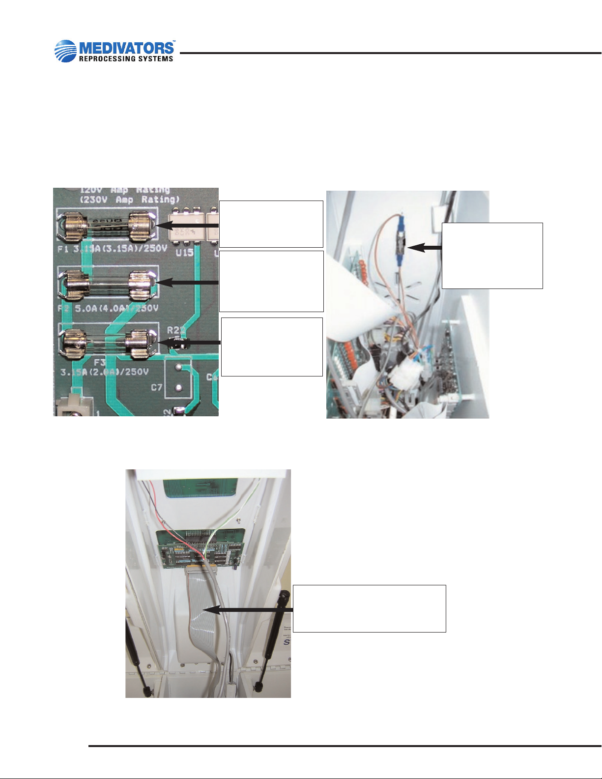
Close-up of Fuses
4
DSD-201 Illustrated Parts Guide
F1 - Fuse
3.15 Amp (Valves)
MF02-0014
F2 - Fuse
5 Amp (Compressor
LCG Pump)
MF02-0017
F3 - Fuse
3.15 Amp
(LCG Heater)
MF02-0014
Fuse 6.25 Amps
Air Line Pressure
Switch Harness
MF02-0018
Interconnect Cable: Control
Panel to Valve Board
MC08-0508
Page 7

Secondary Electronic Assembly: ASM1-0090
With Leak Tester Board
5
50096-127 Revision A
Leak Test Board showing
cables connected
Sensor Harness
MH05-0043
(Not pictured)
Connects to
sensor board
Digital I/O Board
MB01-0017
NOTE: CPU cable
connects here
MC08-0511
Sensor Board
MB01-0018
Leak Test Board (S.I.T.)
(S.I.T. Sheath Integrity Test)
MB01-0020
Digital Output Sheath Cable
MC08-0510
Page 8
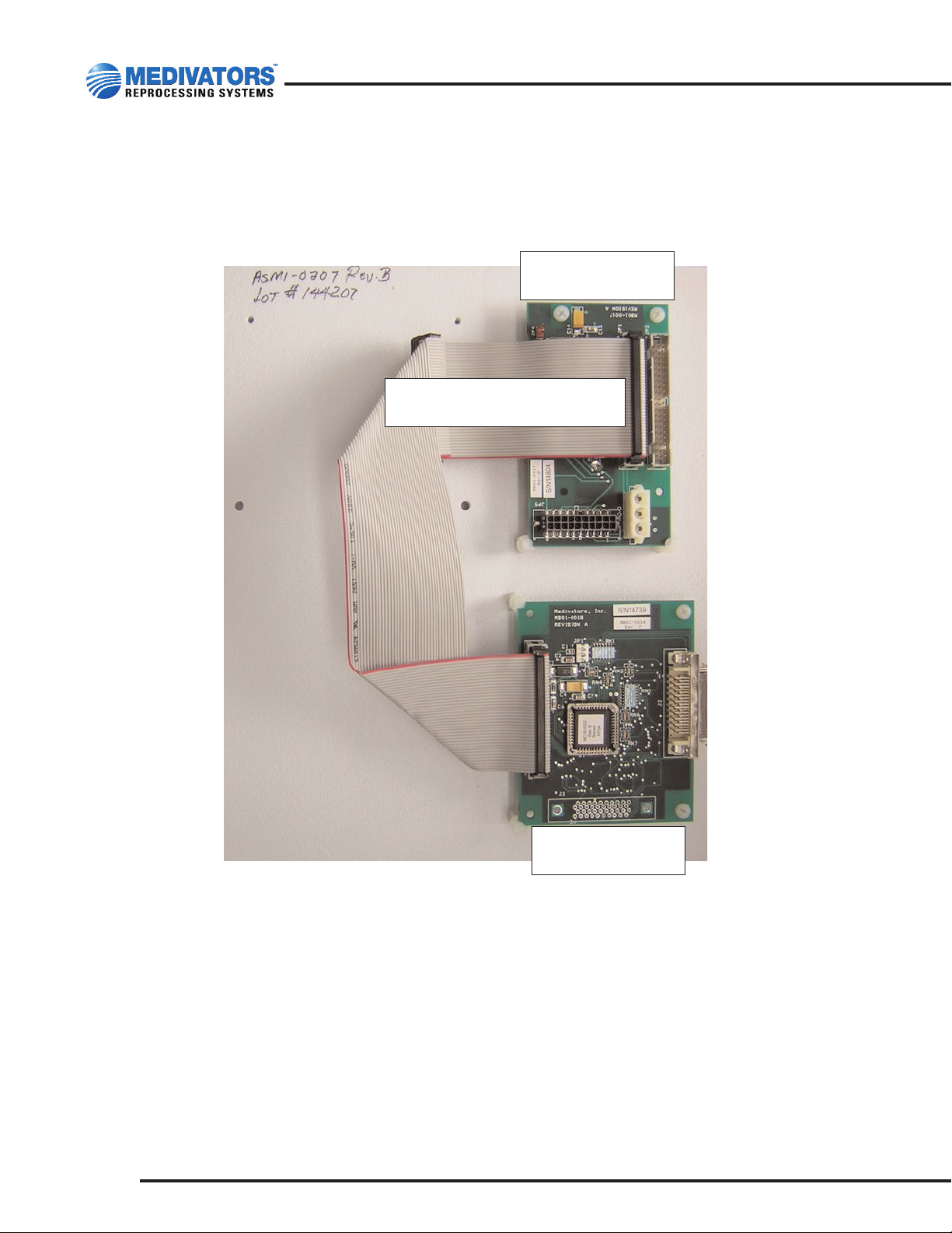
Secondary Electronic Panel
Without Leak Tester Board: ASM1-0207
6
DSD-201 Illustrated Parts Guide
Digital I/O Board
MB01-0017
Sensor Board
MB01-0018
Digital Output Sheath Cable
MC08-0510
Page 9
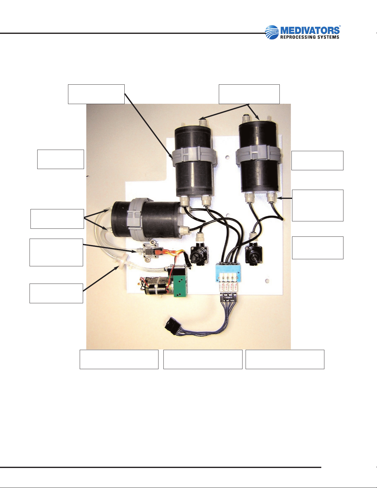
Leak Tester Assembly: ASM1-0080
7
50096-127 Revision A
Connectors
MC10-0019
Press Relief Valve (2)
MV01-0026
Manifold
MM01-0015
Compressor
ASM1-0096
Air Tanks (3)
MW04-0017
Tubing
MT01-0005
Air filter
MF01-0017
Pressure
Switch
MS07-0505
Adapters
(qty 10)
MA01-0048
Black Tubing
MT01-0025
Clamps (3)
MC02-0015
Connectors
MC10-0022
Page 10
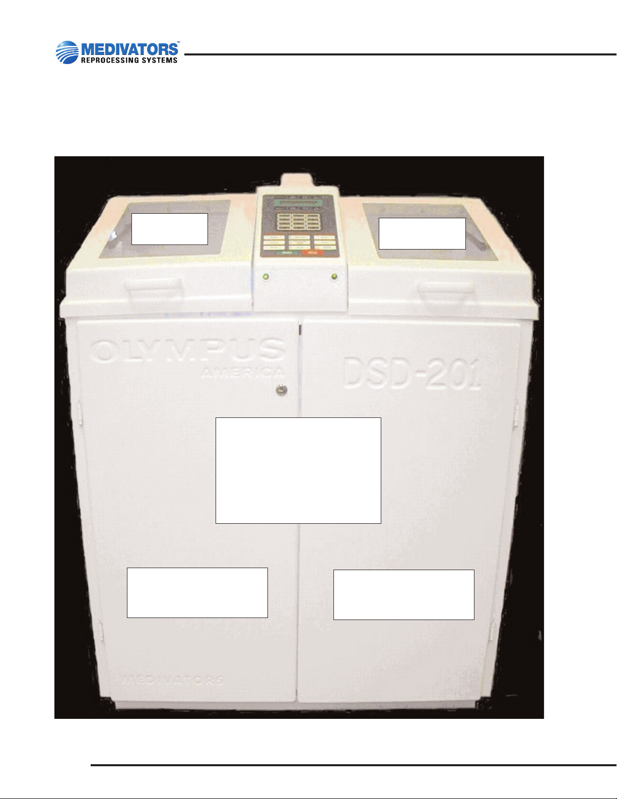
DSD Front View
8
DSD-201 Illustrated Parts Guide
Left Lid
DSD-1065
Right Lid
DSD-1066
Disk Tumbler Door Lock
ML05-0000
Locking Clip (inside of door)
ML05-0001
Key
MK02-0000
Left Door
“Olympus” Embossed
DSD-1058
Right Door
“DSD-201” Embossed
ASM1-0099
Page 11
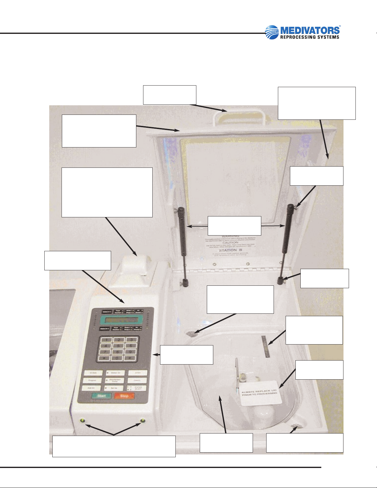
DSD, Top View
9
50096-127 Revision A
Hinge
MH01-0006
Cycle Complete Indicator Light 28v
ML05-0503
Stud Ball
MS02-0000
Gas Springs
MS01-0001
Handle
MH04-0002
Lids
DSD-1065 (left)
DSD-1066 (right)
Lid Gasket Material
(7 ft per side)
MG02-0001
Printer Door
MD01-0008
(large paper roll)
Spindle:
MS16-0000
Hinge:
MH01-0007
Center Console
DSD-1067
Control Panel
MB01-0022
Overflow Drain
Screen
MS09-0003
Temperature
Indicator Strip
ML02-0065
Label
ML02-0030
Floating Lid
DSD-1073
Upper Drain Screen
MS09-0001
Page 12

Basin, Top View
10
DSD-201 Illustrated Parts Guide
Proper basin sensor cap
orientation is show at left
Drain Screen
MS09-0001
Leak Tester
Connector
MC07-0020
Not pictured:
MA01-0048
John Guest Quick
Release Fitting, located
underneath the bulkhead connector
Basin Level Sensor
ASM1-0104
Basin Bridge
Thermistor
MT01-0501
Bulkhead Leak Tester
Connector
MC10-0030
Uses same seal, O-ring and
nut as Basin Sensor
Basin Level
Sensor Cover
MC13-0015
Basin
Connector
MC07-0002
Page 13

Basin, View of Underside
11
50096-127 Revision A
MC07-0014
MN03-0009
MO01-0005
MW02-0008
These items are the
hardware and gasket set
to hold the basin level
sensor.
ME01-0030
MA01-0049
Basin Connector
MC07-0002
Basin Level
Sensor Bulkhead
MB03-0011
Goes on
top side
of Basin
Goes to Bottom
side of Basin
Page 14

Station “A” Main Module Assembly: ASM1-0113
12
DSD-201 Illustrated Parts Guide
Flow Sensor
ASM1-0098
Regulator
Assembly
ASM1-0085
Connector to LCG
Flow Filter
MC07-0015
Side A Disinfectant Pump
78398-466
Adapter
MC07-0004
(to air filter)
Adapter
MA01-0049
Elbow
ME01-0005
Disinfectant Pump
Head Replacement Kit
47049-193
Black Tubing
MT01-0025
Large Tubing
MT01-0024
Air Compressor Assembly:
ASM1-0078
The following are a part of the assembly:
Regulator:
MR01-0001
Gauge: MG01-0000
Early models may not have this
regulator installed. This may have
been installed as an optional upgrade
under P/N:
78398-230
If installing a new compressor in a DSD that doesn’t have this upgrade, contact
Medivators for instructions and additional parts that may be needed.
Air / Valve Manifold
4-Station
MM01-0028
Bleed Valve Solenoid
MM01-0032
Main Manifold
6-Station
ASM1-0117
Page 15

Station “B” Main Module Assembly: ASM1-0115
13
50096-127 Revision A
Elbow
ME01-0005
Disinfectant Pump
Head Replacement Kit
47049-193
Adapter
(to air filter)
MA01-0049
Air / Valve Manifold 6-Station
MM01-0035
Main Manifold 6-Station
ASM1-0117
See next page for detail
Gray Connector to
LCG Flow Filter
MC07-0015
MC07-0011
Inlet Water Connector
(to the 0.2 Micron Filter Housing)
Disinfectant Pump
78398-467
Pump / Switch
Assembly
ASM1-0084
Flow Sensor
ASM1-0098
Regulator
Assembly
ASM1-0085
B-Side Air Compressor Assembly
ASM1-0111
On-Board Pump
Rocker Switch
MS07-0500
Manifold
2-Station
ASM1-0086
Adapter
MA01-0049
3-Way Valve
41600-088
Page 16

Detail of Main 6 Valve Manifold: ASM1-0117
14
DSD-201 Illustrated Parts Guide
Check Valves Alcohol and Detergent
MV01-0039
Main Manifold
6-Station 110V
MM01-0030
Red Locking Clip
(Quantity 5)
ML05-0001
AA
A
A
A
Tubing
MT01-0026
Elbow Swivel
ME01-0028
Adapter 3/8 Post 1/4
(Quantity 2)
MA01-0073
Elbow Swivel
(Quantity 5 - item A)
ME01-0026
Page 17

15
50096-127 Revision A
Valve Block Assembly with
Angled Connection
41600-124
Valve Block Assembly with
Straight Connections
41600-123
Main Manifold Block 6-Station: MM01-0030
Pneumatic Valve Assemblies
Valve Seal Kit
Contains: 4 seals,
screws and Loctite
78398-538
Valve Stem Wrench
is needed to remove
the valve stem
screw.
P/N: MW03-0002
Check Valve Kit
(contains: 1-check valve, 3 O-rings)
MK01-0068
Main Manifold Inlet Base
MB02-0550
Main Manifold Base
MB02-0551
Page 18

Alcohol / Detergent Valves
16
DSD-201 Illustrated Parts Guide
Valve Seal
MV01-0035
Retaining Nut
MN03-0020
Washer
MW02-0170
Valve
MV01-0034
Coil
MV01-0032
Wiring Harness:
43580-100
Detergent
Valve
Alcohol
Valve
Wiring Harness Retention Screw
Page 19

2-Valve Manifold: ASM1-0086
17
50096-127 Revision A
Valve Body
MM01-0020
Contains:
Tee
MT02-0017
Elbow
ME01-0026
Red Locking
Clips
ML05-0001
not seen in this
picture. These
secure the tee
and elbows.
Elbow (2):
ME01-0026
Small Elbow
(on valve block)
ME01-0033
Check Valves
2-Internal
MK01-0068
Top Manifold
Block
MB01-0549
Base
MB01-0552
Valve Block
Assembly
41600-124
Water line
Disinfect Valve
Main
Water
Inlet
Valve
Page 20

3/4” Drain, Cascade Overflow and
Disinfectant Return Valve Assembly: MV01-0022
18
DSD-201 Illustrated Parts Guide
GPVC Valve Cover
MV01-0021
Valve Cover (2)
MC13-0008
Valve Coil Assembly: MH05-0018
O-ring
MO01-0004
Coupling
MC07-0017
Bolts (4)
MS05-0042
Drain Valve
Disinfectant
Return Valve
Disinfectant
Overflow
Valve
Individual Coil
MC15-0000
Connector
MH03-0009
Electrical Contact Pins
30597-211
Page 21

Components of the 3/4” Valve Rebuild Kit: MK01-0029
19
50096-127 Revision A
Coil Retention Clip
MC02-0023
Spring
MS01-0003
NOTE: Proper orientation
is critical
MC13-0008 or MV01-0021
are not included in the
MK01-0029 Kit. Shown for
illustrative purpose only.
3/4” Valve Kit with Coil
MK01-0016
This includes the parts in the
MK01-0029
plus one Coil:
MC15-0000
Small O-ring
MO01-0022
Wave Washer
MW02-0019
Plunger Housing
MV01-0044
Bolts
MS05-0107
Washer
MW02-0004
Plunger
MP07-0507
Large O-ring
MO01-0018
Electrical Contact Pins
30597-211
Page 22
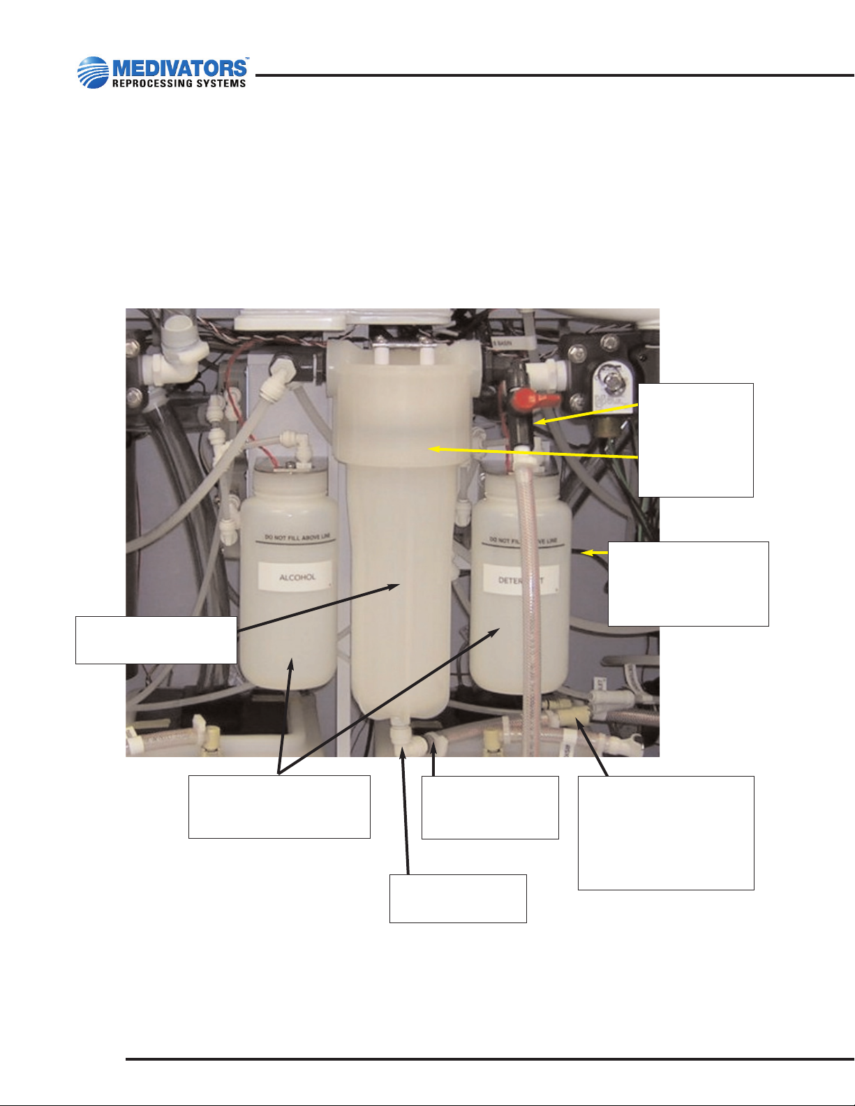
Alcohol / Detergent and Internal Water Filter Assemblies
ASM1-0127: Alcohol and Pump Assembly
ASM1-0128: Detergent, Pump and 0.2 Micron Filter Assembly
ASM1-0166: Alcohol / Detergent Bottle Sub-Assembly
used on above assemblies.
20
DSD-201 Illustrated Parts Guide
Coupling
MC07-0003
Connects to
MC07-0011 on
ASM1-0115
(pg. 13)
Bleeder Valve
MV01-0020
O-ring
MO01-0020
Detergent / Pump &
0.2 Micron Filter
Housing Assembly
ASM1-0128
3/8 Adapter with
Barbed Fitting
MC07-0021
Alcohol or Detergent
Bottle Sub-Assembly
ASM1-0166
Water Filter Housing
MH03-0030
Elbow
ME01-0028
Page 23

Alcohol Assembly: ASM1-0127
21
50096-127 Revision A
Alcohol / Detergent
Float Sensor
MS03-0011
Alcohol / Detergent
Cap
MC06-0511
Inlet Check
Valve
MV01-0040
Peristaltic Pump
Tube Set
MT01-0500
Alcohol or
Detergent
Bottle
MR06-0004
Elbow Fittings
ME01-0037
Tee Connector
MT02-0023
Peristaltic Pump
MP01-0013
Page 24

Early Style 0.2 Micron Internal Water Filter Housing
22
DSD-201 Illustrated Parts Guide
This Stainless Steel
0.2 Micron Water Filter
Housing is obsolete.
Replacement Kit
MK01-0071
(see next page)
3/8 Adapter
w/Barbed Fitting
MC07-0011
Elbow
ME01-0027
Page 25

Plastic Filter Housing : MK01-0071
Replacement for the Stainless Steel Filter Housing
23
50096-127 Revision A
Bleed Valve
MV01-0020
Water Inlet Line
Replace straight adapter
with elbow adapter
ME01-0027
Other parts needed:
ME01-0027 Qty 1
MT01-0024
Qty 4 ft. of Tubing
MK01-0071 is designed for the DSD-91E. To install in the DSD-201, contact the
Technical Assistance Center at 1-800-848-9024.
Page 26

LCG Reservoir Assembly with Heat: ASM1-0204
Heater Assembly: ASM1-0099
24
DSD-201 Illustrated Parts Guide
This LCG tank has
been phased out.
Repair parts will be
available. If
replacement tanks
are needed,
see pg. 26 for the
part numbers.
S/S Heater
500W-110V
MH02-0002
Temperature
Probe
MP09-0000
Connects to the
temperature
controller
Reservoir Level
Float Sensor
ASM1-0097
Heater
Temperature
Controller is
obsolete
MC06-0001
To replace this with
the Digital
Controller, order kit
P/N: 78398-131.
This includes
mounting bracket,
hardware and
instructions.
Reservoir
Thermistor
MT10-0500
Connects to the
CPU
Page 27

New Style LCG Reservoir Assembly
25
50096-127 Revision A
Side B Heated LCG
Reservoir Tank
78398-842
LCG Uptake Tube Assembly
(view is from inside the LCG tank)
78399-249
Side A Heated LCG
Reservoir Tank
78398-647
Digital Temperature
Control
39500-020
Page 28

New Style LCG Reservoir Assembly (continued)
26
DSD-201 Illustrated Parts Guide
Heater coil
39500-021
In-line
Coupling
MC07-0022
Temperature
Probe
MP09-0000
(Feeds back to
temperature
controller)
Caution Label
(paper towels)
67198-533
Reservoir
Thermistor
MT10-0500
(sends LCG
temperature to
CPU)
LCG Float
Level Sensor
35548-032
Nut
42600-018
LCG Reservoir
Lid
75227-345
Snap on Lid
43086-000
(Provides
access for
testing LCG)
Elbow Connector
ME01-0018
Connects to
47509-374 Quick
Connect Adapter
Page 29

Air Tank: MT03-0023
27
50096-127 Revision A
Pressure Switch
MS07-0508
Early model DSD’s
may have a Tee Fitting
P/N MT02-0023
Elbow & Threaded
Fitting
ME01-0028
Page 30

GFI Assembly: ASM1-0087
28
DSD-201 Illustrated Parts Guide
GFI Assembly
ASM1-0087
GFI Receptacle
MR06-0003
Power Cord Assembly
ASM1-0203
Page 31

Filters and Accessories:
All items in this section are ordered through Olympus Customer Service.
Water Filters come in a quantity of 1 each
29
50096-127 Revision A
MF01-0014
1 Micron Pre-Filter
A filter change log sheet is located on the
Medivators website at: www
.minntech.com.
Move your mouse to the Medivators
Reprocessing tab on the menu bar, click on
Resource Center, then User Library, then
select DSD-201 from the Document
Categories drop down menu. Go to the
Report Forms Section.
MF01-0015
0.45 Micron Pre-Filter
MF01-0013
0.2 Micron Final Water Filter
MF01-0011
LCG Filter (Pack of 12)
MF01-0028
Air Filter (Pack of 8)
Page 32

CB12-0002
Small Accessory Bag (Pack of 2)
MS07-0002
Rapicide MEC Test Strips (Pack of 2)
Endoscope Hook-ups
The endoscope hook-ups (or tubing sets) vary according to endoscope manufacturer and endoscope model
number. To determine the correct tubing set, have available each endoscope model number used and call the
Help Desk for assistance. This information is also available at the Medivators website located at:
www
.minntech.com. Move your mouse to the Medivators Reprocessing tab on the menu bar, click on Resource
Center, then User Library, then select DSD Hook-ups from the Documents Categories drop down menu. Go to
the second section, Hook-up Matrixes. If your endoscope manufacturer or model is not listed, contact Medivators
for assistance.
30
DSD-201 Illustrated Parts Guide
Page 33

Page 34

Minntech Corporation
14605 28th Avenue North
Minneapolis, MN 55447 USA
Phone: (763) 553-3300
Toll Free: (800) 328-3340
Fax: (763) 553-3387
website: www.minntech.com
Minntech BV
Sourethweg 11
6422 PC Heerlen
The Netherlands
Phone: +31 45 5471 471
Fax: +31 45 5429 695
email: info@minntechbv.com
Minntech International
Singapore Representative Office
No. 138 Robinson Road
#15-09/10 The Corporate Office
Singapore 068906
Tel: +65 6277 9698
Fax: +65 6225 6848
Minntech UK
Unit 1A, Willow House
4 Stubley Hollow
Dronsfield
Sheffield S18 1PA
United Kingdom
Tel: +44 1246 410 147
Fax: +44 1246 411 606
Minntech Beijing Representative Office
AVIC PLAZA, Room 1508B
No. 2 Dongsanhuan South Road
Beijing 100022, China
Tel: +8610 6567 8446
Fax: +8610 6567 8445
Manufactured in the USA by:
A Minntech Corporation Business Group
 Loading...