

Page 1
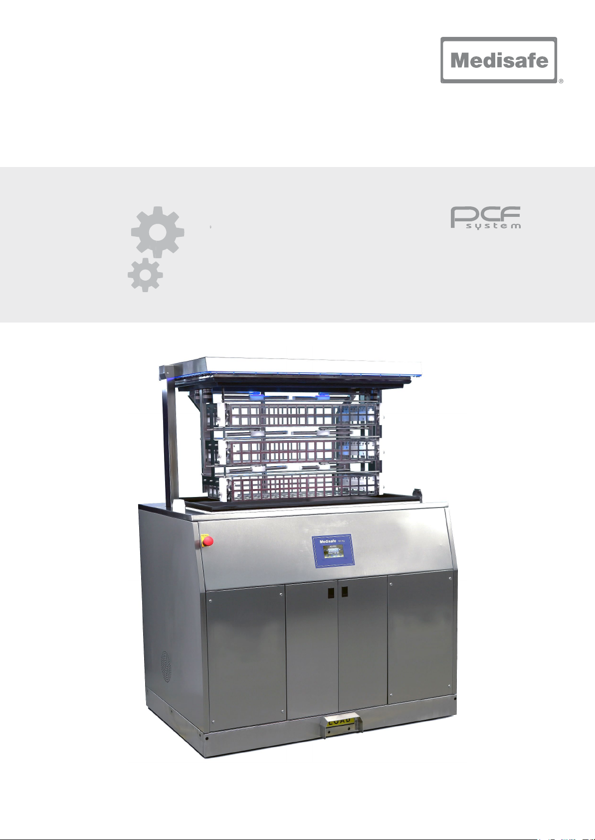
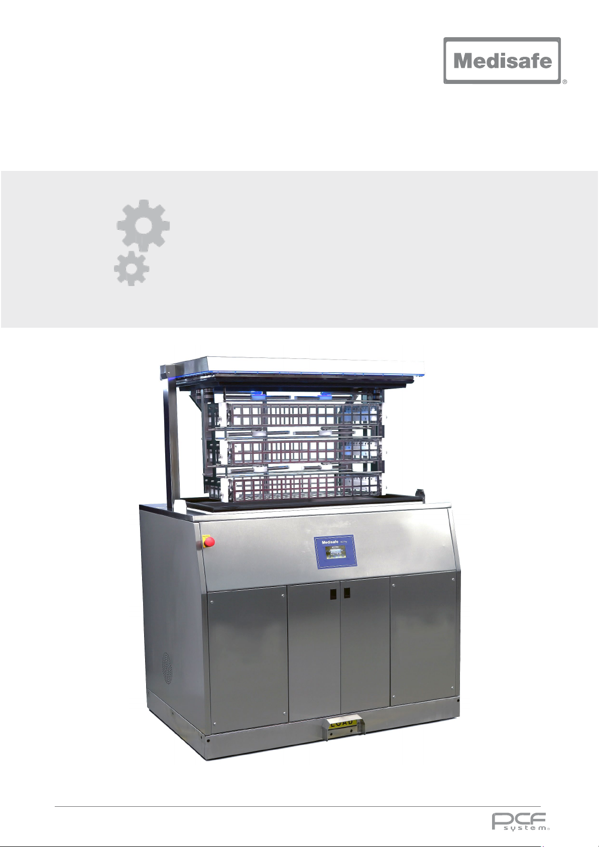
PCF Pro
User Manual
DOC01851
Page 2

PCF Pro User Manual
COPYRIGHT© 2018 MEDISAFE. ALL RIGHTS RESERVED
REPRODUCTION OF THIS MANUAL IN ANY MEDIUM WITHOUT THE EXPRESS PERMISSION OF
MEDISAFE IS PROHIBITED.
LIMITED RIGHTS NOTICE TECHNICAL DOCUMENTATION/DATA
This technical manual shall not, without the written permission of MEDISAFE be either (a) used,
released, disclosed, or reproduced in whole or in part or (b) used in whole or in part for manufacture
except that (i) such release, disclosure or use is necessary for emergency repair or overhaul; (ii) such
release, disclosure, or use is made subject to a prohibition that the person to whom the data is
released or disclosed may not further release, disclose, or use such data; (iii) MEDISAFE is notified of
such release, disclosure or use.
DOC01851 Page 2 of 74
Page 3
PCF Pro User Manual
R
D
BY
D
Amended Ultrasonics frequency in the general
Record of Revisions
EVISION
NUMBER
1 Original Issue. W. Leslie 12-Jan-17
ESCRIPTION OF CHANGE / LOCATION OF CHANGE
ATE
2 Updated certification section, direction pump, changed
carrier name to basket.
3 Updated PCF Pro parameters. Added copyright
information, table of revision, luer pipes sections.
specifications section. Amended daily check section.
E. De Bruijn 11-Aug-17
W. Leslie
A. Ahmed
24-Aug-17
30-Jan-18
DOC01851 Page 3 of 74
Page 4
PCF Pro User Manual
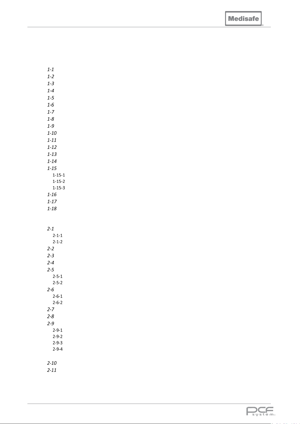
Table of Contents
1. INTRODUCTION ............................................................................................................................................ 7
Medisafe Contact Details ......................................................................................................................... 8
Independent Monitoring .......................................................................................................................... 9
Service and Maintenance Requirements ................................................................................................. 9
PCF Pro Warranty Registration .............................................................................................................. 10
Safety Precautions ................................................................................................................................. 12
Training Personnel ................................................................................................................................. 15
Compliance ............................................................................................................................................ 16
Product Identity ..................................................................................................................................... 16
Manufacturer Information ..................................................................................................................... 16
Intended Use ........................................................................................................................................ 17
Performance ........................................................................................................................................ 17
Cycle Record ......................................................................................................................................... 17
Cycle Failure ......................................................................................................................................... 17
Concept Summary ................................................................................................................................ 17
General Safety...................................................................................................................................... 18
Chemicals ....................................................................................................................................................... 18
Decontamination ........................................................................................................................................... 18
Heat................................................................................................................................................................ 18
Electrical Safety .................................................................................................................................... 18
Service Contracts & Warranty.............................................................................................................. 18
Validation Option ................................................................................................................................. 18
2. INSTALLATION ............................................................................................................................................ 19
Transport and Storage ........................................................................................................................... 20
Marking ............................................................................................................................................................ 20
Environmental .................................................................................................................................................. 20
Lifting ..................................................................................................................................................... 20
Unpacking .............................................................................................................................................. 20
Returns ................................................................................................................................................... 20
Enclosures Check List ............................................................................................................................. 21
PCF Pro Accessory Kit (MP21223) .................................................................................................................... 21
PCF Pro Plumbing Kit (MP21225) ..................................................................................................................... 21
Additional Accessories ........................................................................................................................... 22
Printer .............................................................................................................................................................. 22
Approved Chemicals ........................................................................................................................................ 22
Installation Requirements ...................................................................................................................... 23
Connecting the PCF Pro .......................................................................................................................... 25
Installation Drawings ............................................................................................................................. 26
Rear View Showing Services............................................................................................................................. 26
Front View ........................................................................................................................................................ 27
Left Side View with Lid Closed showing Drain Connection .............................................................................. 28
Left Side View Lid Open ................................................................................................................................... 29
CONNECTING TO THE RS232 PORT ........................................................................................................................... 30
Thermal Printer .................................................................................................................................... 30
Data Logging PC................................................................................................................................... 30
3. OPERATION ................................................................................................................................................ 31
DOC01851 Page 4 of 74
Page 5
PCF Pro User Manual
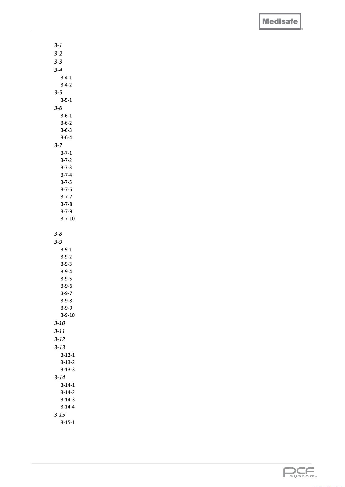
Menu ...................................................................................................................................................... 32
Power Up ............................................................................................................................................... 33
Authorisation code ................................................................................................................................. 33
Setting Time & Date ............................................................................................................................... 34
Set Time ........................................................................................................................................................... 34
Set Date ............................................................................................................................................................ 34
Selecting a program ............................................................................................................................... 35
Standard Program Parameters......................................................................................................................... 35
Chemical Handling ................................................................................................................................. 36
Chemical Consumption .................................................................................................................................... 36
Chemical Replacement .................................................................................................................................... 36
Disposal of chemical containers ....................................................................................................................... 36
Chemical Priming ............................................................................................................................................. 36
Baskets ................................................................................................................................................... 37
Basket Removal ................................................................................................................................................ 37
Basket Insertion ............................................................................................................................................... 37
Luer pipes ......................................................................................................................................................... 38
Instruments ...................................................................................................................................................... 39
Instrument Loading Precautions ...................................................................................................................... 39
Carrier Lift Controls .......................................................................................................................................... 40
Light Guard....................................................................................................................................................... 40
Safety Edge ...................................................................................................................................................... 40
Emergency Stop ............................................................................................................................................... 40
Testing Operation of the Safety Devices ........................................................................................................ 41
To check operation of the carrier lift:........................................................................................................................ 41
Starting a Cycle ...................................................................................................................................... 42
Automated Wash Cycle .......................................................................................................................... 43
Cycle Process .................................................................................................................................................... 43
Pre-wash .......................................................................................................................................................... 44
Wash ................................................................................................................................................................ 44
Rinse................................................................................................................................................................. 45
Final Rinse/Disinfection ................................................................................................................................... 45
Cooling ............................................................................................................................................................. 46
Drying ............................................................................................................................................................... 46
Cycle Complete ................................................................................................................................................ 46
Unload .............................................................................................................................................................. 46
Re-Wash Cycle ............................................................................................................................................... 47
Cycle Errors .......................................................................................................................................... 48
Aborting a Cycle ................................................................................................................................... 48
LED Edge .............................................................................................................................................. 49
Routine Maintenance........................................................................................................................... 49
Before Every Cycle ......................................................................................................................................... 49
Daily Checks ................................................................................................................................................... 50
Weekly checks ................................................................................................................................................ 51
Decontamination Guide ....................................................................................................................... 52
Daily Cleaning/ Procedure.............................................................................................................................. 52
Full Decontamination ..................................................................................................................................... 52
Pre Transport Procedure ................................................................................................................................ 52
Decontamination Certificate .......................................................................................................................... 53
Downloading the Cycle Log .................................................................................................................. 54
Download Logs ............................................................................................................................................... 54
4. TROUBLESHOOTING ................................................................................................................................... 55
DOC01851 Page 5 of 74
Page 6
PCF Pro User Manual
Error Messages ...................................................................................................................................... 56
Other Faults ........................................................................................................................................... 58
5. TECHNICAL ................................................................................................................................................. 59
General Specifications ............................................................................................................................ 60
Applied Standards .................................................................................................................................. 64
6. APPENDICES ............................................................................................................................................... 65
EMC .................................................................................................................................................................. 66
EMC & Electromagnetic Compatibility Data .......................................................................................... 66
Electromagnetic Emissions .................................................................................................................... 67
Electromagnetic Immunity ..................................................................................................................... 68
Separation Distances Between PCF Pro and Mobile RF Equipment ....................................................... 70
Warranty ................................................................................................................................................ 71
Service Record ........................................................................................................................................ 72
Operator PIN Number Codes.................................................................................................................. 73
Symbols Glossary ................................................................................................................................... 74
DOC01851 Page 6 of 74
Page 7
User Manual
1. Introduction
1. Introduction
DOC01851 Page 7 of 74
Page 8

PCF Pro User Manual
Medisafe Contact Details
United Kingdom
(Manufacturing, Sales, Customer Service & Technical Support)
Medisafe UK Ltd
Unit 1 Twyford Industrial Estate
Twyford Road
Bishop’s Stortford
Hertfordshire CM23 3LJ
England
Tel: +44 (0) 1279 461641
Fax: +44 (0) 1279 461643
E-mail [email protected]
www.medisafeinternational.com
DOC01851 Page 8 of 74
Page 9
PCF Pro User Manual
Introduction
Important
Read this entire manual before attempting to install, operate or perform any
maintenance on the Parametric Controlled Flow (PCF) Pro Ultrasonic Cleaning
System. Ensure all appropriate personnel understand the contents of this manual.
This Operating Manual contains important information on proper use and maintenance of the PCF Pro
Ultrasonic Cleaning System. All personnel involved in the use and maintenance of this equipment
must carefully review and comply with the warnings, cautions and instructions contained in this
manual. These instructions are important to protect the health and safety of personnel operating the
Ultrasonic Cleaning System and should be retained in a conveniently accessible area for quick
reference.
Advisory
A listing of the Safety Precautions to be observed when operating the PCF Pro Ultrasonic Cleaning
System is found in Section 1-5 of this manual. Do not operate the equipment until you have become
familiar with this information.
Independent Monitoring
Important Note for the Product Owner
It is advised that an independent monitoring system is fitted in accordance with ISO 15883-1:2009 Washer-disinfectors.
Service and Maintenance Requirements
The PCF Pro should be serviced on a regular basis to ensure that the product continues to perform in
accordance with its design parameter, see section 6-6 for more information.
DOC01851 Page 9 of 74
Page 10
PCF Pro User Manual
halts carrier lifting system
raises up by approximately 30mm
For one side test Safety Edge activation during upward
motion halts the lifting system
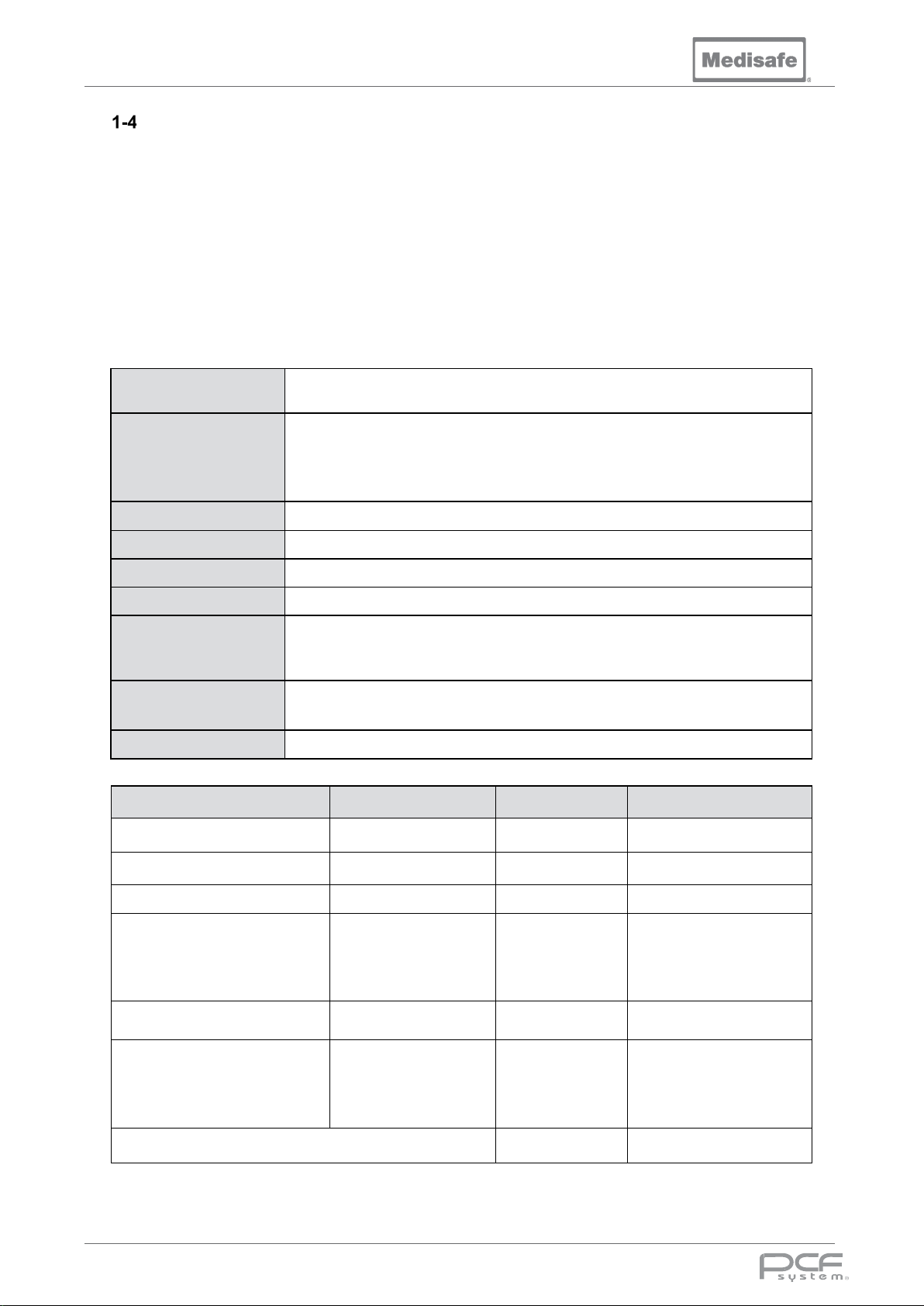
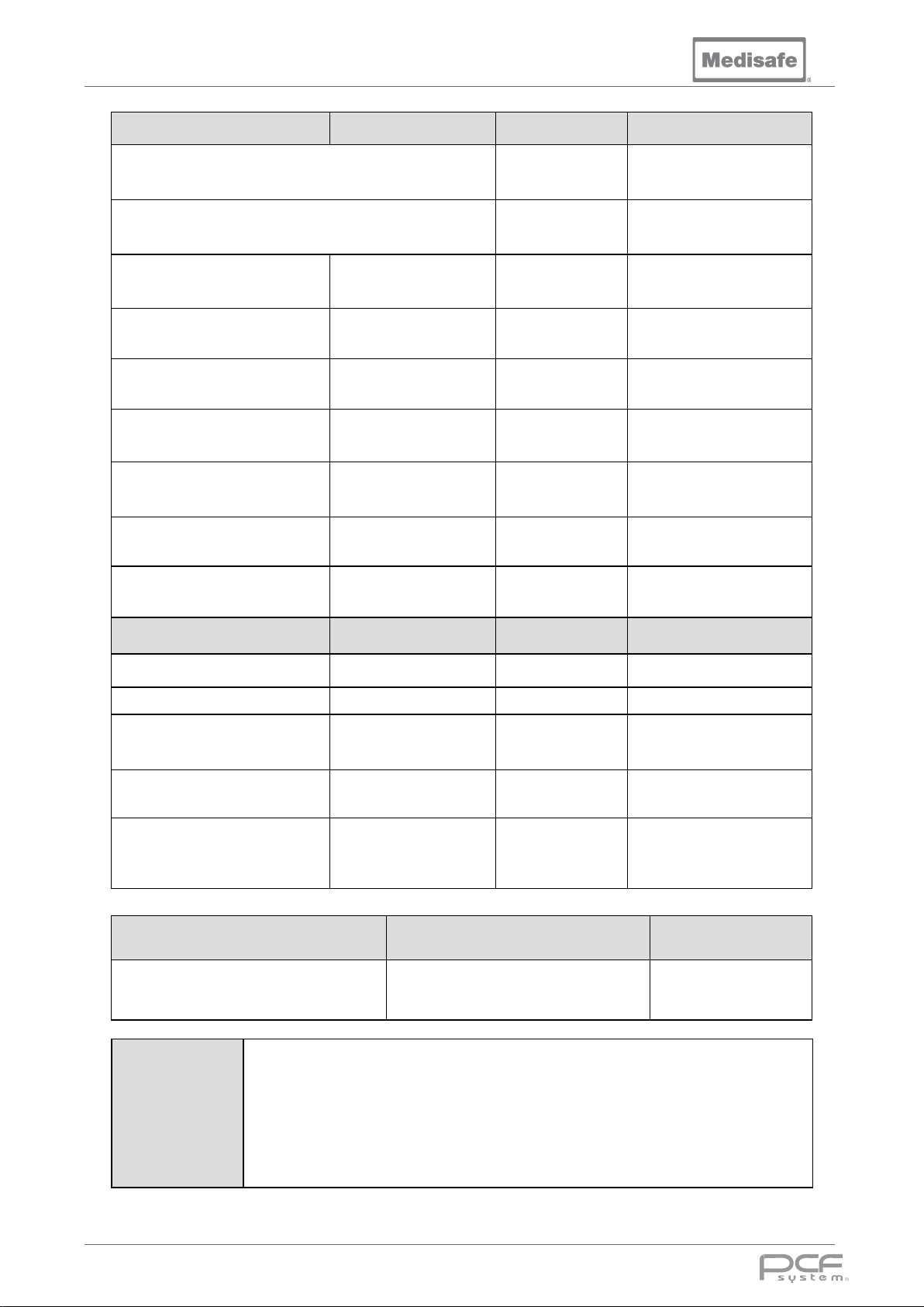
PCF Pro Warranty Registration
Important Note for the Installer
This Registration Form MUST be completed by the person undertaking installation and witnessed by
the owner of the product. In the event of a Warranty Claim, the information contained within this
Registration is your evidence that the product has been correctly installed. Failure to provide this
evidence in the event of a warranty claim may result in the claim being rejected (this does not affect
your statutory rights as a customer). A copy of this form must be sent to your local Medisafe
authorised distributor to validate the warranty.
Tests parts one and two must be completed by the engineer commissioning the PCF Pro for warranty
registration purposes. Where no value is required write pass or fail with a comment if necessary.
For installation instructions and contact information for qualified personnel who can perform the
installation, please contact Medisafe (see section 1-1).
Owner Name:
Installation Address:
Installation Date:
Model No:
Serial No:
Software Version:
Installed by:
Witnessed by:
Position:
Part 1, Test Type Acceptable Value Result Comments
Drains remove effluent effectively
Phase sequence, Pump Rotation
Support bases secure
There is no evidence of
interference to or from other
equipment connected to the
same services
-
-
-
-
Emergency stop operates and
For all 5 sections test Safety
Edge activation during downward
motion halts lifting system then
DOC01851 Page 10 of 74
-
-
Page 11
PCF Pro User Manual
Test Through beam sensor basket obstruction along
Test Through beam sensor basket obstruction along
<300µS/cm (Soft)
Part 1, Test Type Acceptable Value Result Comments
machine front edge during downward motion halts lifting
system then raises up by approximately 30mm
machine front edge during upward motion halts lifting
system
Compressed Air
Hot Water Hardness (As
specified by WD Manufacturer)
Cold Water Hardness (As
specified by WD Manufacturer)
Hot Water Temperature
Cold Water Temperature
Hot Water Pressure
Cold Water Pressure
5.5 – 7 bar
(80 - 100 psi)
125 ppm (max)
125 ppm (max)
50°C (122°F) min
80°C (176°F) max
5°C (41°F) min
30°C (86°F) max
2 - 5 bar
(30 – 70 psi)
2 – 5 bar
(30 - 70 psi)
Part 2, Final rinse water Acceptable Value Result Comments
Rinse water supply Type
If softened, Hardness
Water Pressure
Temperature
Electrical conductivity
RO, DI, Softened
< 125 ppm
2 – 5 bar
(30 – 70 psi)
5°C (41°F) min
80°C (176°F) max
<30µS/cm (RO)
<10µS/cm (DI)
Signed Name Date
Comments /
remedial work
DOC01851 Page 11 of 74
Page 12
PCF Pro User Manual
Wear appropriate Personal Protective Equipment (PPE) whenever handling
Wear appropriate Personal Protective Equipment (PPE) whenever removing
Since temperatures within the unit can reach 92°C (198°F) during and after
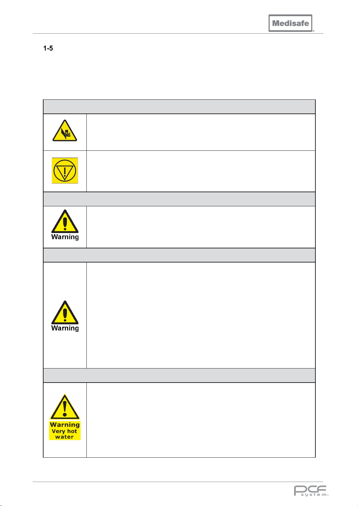
Safety Precautions
The following Safety Precautions must be observed when operating or servicing the PCF Pro.
WARNING indicates the potential for personal injury and CAUTION indicates the potential for damage
to equipment. For emphasis, certain Safety Precautions are repeated throughout the manual. It is
important to review ALL Safety Precautions before operating or servicing the unit.
Warning – Pinching Hazard
Pinch points are created during lid articulation. Keep hands clear when opening or
closing the lid.
In the unlikely event of an uncontrolled fault, the emergency stop button can be
pushed to cut power for the Carrier Lift and other critical outputs.
Warning – Breathing Hazard
Some cleaning solutions emit harmful vapours. Only use cleaning solutions in wellventilated areas. Do not inhale vapours. Do not permit solution vapours to exceed
maximum allowable concentrations in the work area. Ensure adequate ventilation.
Warning – Chemical Burn and/or Eye Injury Hazard
• Detergents are caustic and can cause adverse effects to exposed tissues. Do
not get in eyes, on skin or attempt to ingest by mouth.
• Read and follow precautions and instructions on detergent label and in the
Material Safety Data Sheet (MSDS) prior to handling chemical, refilling chemical
containers or servicing chemical injection pumps and lines.
•
chemicals or servicing chemical injection pumps and lines. This should include
plastic gloves, goggles or full-face visor, and disposable plastic apron.
•
baskets or parts from cleaning chamber.
• In case of body contact with chemical, always follow emergency procedure given
in that chemical’s MSDS or call emergency services.
• Use a funnel when transferring any chemical from one container to another.
Warning – Burn Hazard
•
operation, take care when opening lid at the end of a cycle. Allow sufficient time
for items to cool before handling, cleaning or maintenance procedures.
• Wear appropriate Personal Protective Equipment (PPE) whenever reaching into
Chamber after a thermal disinfection operation.
• Under no circumstances attempt to forcibly open the lid during operation.
• During reloading of instruments in the re-wash program the water temperature
within the unit can reach 60°C (140°F), when opening the lid and reloading the
instruments take care and wear appropriate PPE.
DOC01851 Page 12 of 74
Page 13
PCF Pro User Manual
detergent mix in cleaning chamber. Never use
or electric shock, do not expose equipment to
Isolate electrical supply by turning the buildings disconnect switch to OFF
immediately wipe up any spilled liquid or
condensation. If spills or leaks could contain detergents or other chemicals,
t or
. Maintenance performed by unqualified
Regularly scheduled preventive maintenance, in addition to the faithful
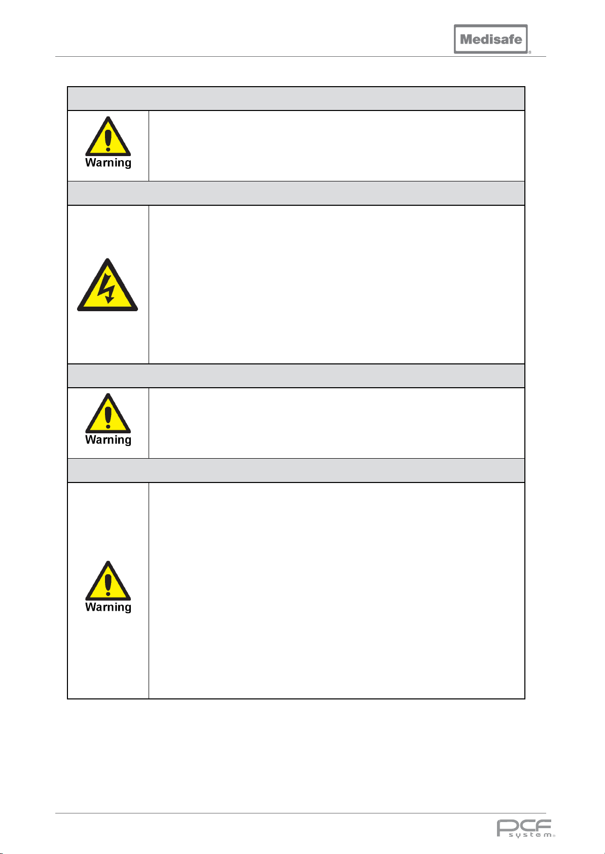
Warning – Explosion Hazard
Use only water or waterflammable or combustible cleaning liquids. Fire or explosion could result.
Warning – Electric Shock Hazard
• To prevent the risk of fire
unnecessary moisture. Always ensure that all external surfaces are dried after
each cycle.
• When removing a basket, allow to drain into the chamber before moving to the
next cleaning station. Excess water spillage may cause electrical shock and
serious injury.
• Disconnect all utilities to unit before servicing. Do not service unit unless all
utilities have been properly locked out. Always follow local occupational health
and safety regulations, as well as electric and plumbing codes.
•
before checking or replacing any parts. Electrical shock can cause serious
injury.
Warning – Slipping Hazard
To avoid slippery floor conditions,
follow safety precautions and handling procedures set forth on detergen
chemical label and/or MSDS.
Warning – Personal Injury and/or Equipment Damage Hazard
• Only Medisafe or Medisafe-trained service personnel must make repairs and
adjustments to this equipment
personnel or installation of unauthorized parts could cause personal injury,
result in improper equipment performance, invalidate the warranty, or result in
costly damage. Contact Medisafe regarding service options.
•
performance of routine maintenance described within the service manual, is
required for safe and reliable operation of this equipment. Contact Medisafe to
schedule preventive maintenance.
• Failure to perform periodic service inspections of the machine could result in
serious personal injury or equipment damage.
• Do not wear loose fitting clothing, neckties or jewellery that could become
entangled in moving parts.
• Never reach into a chamber when unit is in operation.
• Always use a basket to reprocess instruments within the unit.
• Never reach into a chamber if the carrier lift is jammed.
DOC01851 Page 13 of 74
Page 14
PCF Pro User Manual
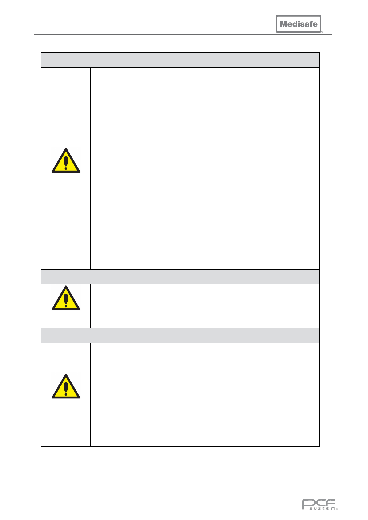
When choosing a detergent, select one with a low chloride content.
and forth motion, in same direction as surface grain.
into the tank.
port. Otherwise, wash
• Always confirm compatibility with the instrument manufacturer.
f any instruments became detached from the Medisafe connection tubing
connection is firmly seated.
Caution – Possible Equipment Damage
• Never place items or person(s) on the lid, this is particularly important while
operating the carrier lift.
• Ensure the thumb ball latches in the down position before moving the carrier
lift.
• Never place items on the machine which could obstruct the lid from closing.
• Never attempt to obstruct the lid from closing.
• All baskets must be fitted when running a cycle.
• Do not place items directly into the wash tank or allow them to make contact
with the tank sides.
• Never scratch chamber walls. This can increase cavitation erosion.
• Do not load basket with instruments pointing at the lid.
• Do not overload the basket, maximum load of 10kg (22lbs) per basket.
• Do not allow Luer pipes to protrude from the basket.
Caution
• Always use a Full DIN Tray Standard to hold instruments (M20044).
•
Detergents with a high chloride content can be harmful to stainless steel.
• Repeated fuse blows or circuit breaker trips indicate a short circuit or overload.
Have a fully trained technician locate and correct situation.
• Use nonabrasive cleaners when cleaning unit. Follow directions on container
and rub in a backAbrasive cleaners damage stainless steel. Cleaner rubbed in a circular motion
or applied with a wire brush or steel wool will scratch and dull stainless steel.
• Avoid running equipment into the Control Panel or Touch Screen to prevent
damage to controls.
• When removing baskets always tilt down to ensuring any retained water drips
Caution – Chemical
• Chemical bottles must be connected to the correct
efficiency and/or rinsing will be compromised. Ensure that the chemical type
Caution
matches the port shown on the display.
• Check chemical bottles are in date before use
Caution – Instrument Care
• Always follow the manufacturer’s instructions if processing instruments with
special characteristics e.g. fibre optics or rigid optics.
• Whether pre or post processing instruments, always follow the manufacturer’s
instructions.
• Always attach tubing to a suitable size distal connector for instruments being
Caution
cleaned or to a quick connect port if the instrument has one.
• Always open box jointed instruments.
• Always ensure taps are open on cannulated instruments.
• Always dissemble instruments that are designed to be taken apart.
• Visually inspect instruments after reprocessing
• I
during processing, they should be reprocessed after ensuring that the Luer
DOC01851 Page 14 of 74
Page 15
PCF Pro User Manual
Training Personnel
The owner of this equipment has the responsibility for training the users and keeping the appropriate
records.
There should be regular training of all personnel concerned with the operation and
maintenance of the equipment. The training schedule shall include:
• Operation of the machine (see section 2-10, 3-1, 3-4-1, 3-4-2, 3-5, 3-7 , 3-8, 3-9 and 3-
12).
• Safe use of machine (see section 1-5)
• Chemical handing (see section 3-6)
• Emergency Procedures e.g. how to handle the load in case of aborted cycle (see
section 3-9-10 and 3-11)
• Regular maintenance procedures (see section 3-13 and 3-14)
• Troubleshooting (see section 4)
The following table can be used for keeping training records.
Date Name Title of Training Signature of Trainer
DOC01851 Page 15 of 74
Page 16
PCF Pro User Manual
Compliance
The PCF Pro has been designed to perform
within the guidelines recommended by
international decontamination Standards. A
stringent quality control program ensures that
every unit is manufactured and tested under
controlled conditions to ensure that all
products perform identically.
Commitment to RoHS and WEEE
Requirements
Medisafe is committed to meeting or
exceeding the requirements of the RoHS CE
Marking directive (2011/65/EC) (Restriction of
the Use of Certain Hazardous Substances in
Electrical and Electronic Equipment).
Medisafe is also committed to meeting all
requirements of the WEEE directive
(2012/16/EU) (Waste Electrical and Electronic
Equipment).
WEEE and Battery Disposal
Waste electrical and electronic
products must not be placed in the
general refuse but collected
separately. Separately collected
WEEE products are to be sent to an approved
recycling or disposal operators for safe
recycling, recovery or reuse.
Medisafe UK Ltd is registered with the "B2B
Compliance" Scheme. B2B Compliance on
behalf of Medisafe, takes on the legal
responsibilities of the reporting, collection and
treatment of, all WEEE that Medisafe UK Ltd is
obligated for - and ensures that the
appropriate recycling targets are met. .For
independent confirmation of Medisafe UK Ltd
status can call B2B Compliance on 0845 680
9829 or visit www.b2bcompliance.org.uk
To fulfil our B2B WEEE take-back obligations,
B2B Compliance will undertake the
appropriate collection and disposal of
obligated products of Medisafe UK Ltd.
If a Medisafe Product has reached its end of
life, please contact B2B Compliance
collections team on 0845 680 9829 or
collection and treatment.
Otherwise, please recycle where facilities
exist. Check with your Local Authority or
Distributor for recycling advice.
.
to arrange
Declaration of CE Conformity
The PCF Pro is designed and manufactured in
the UK by Medisafe UK Ltd. and complies with
the essential requirements of the Medical
Devices Directive 93/42/ EEC (where
appropriate). All products are CE compliant
and are registered as Class IIb devices
through the application of rule 15 within Annex
IX of the Medical Devices Directive 93/42/
EEC.
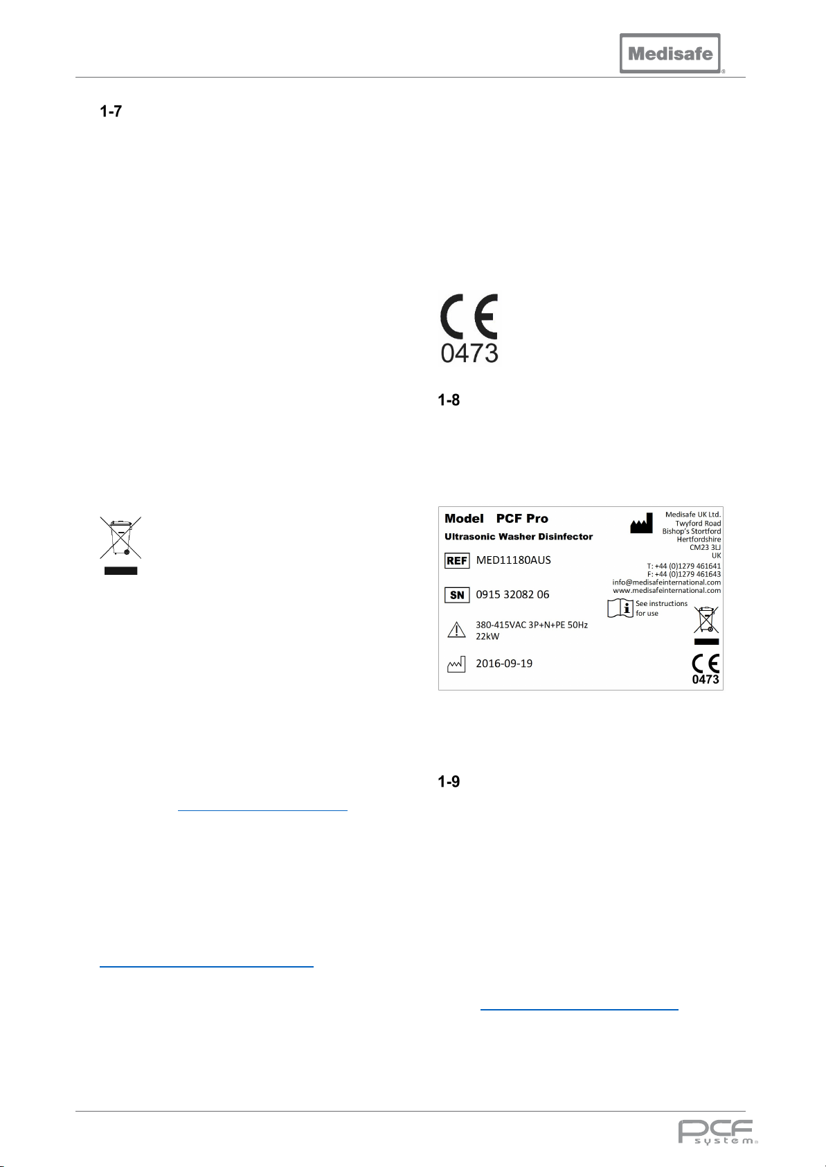
Product Identity
The model and serial number label are located
on the inside panel of the chemical
compartment.
Example of serial number label:
The software version is shown on the front
panel display when the unit is first switched on.
Manufacturer Information
Medisafe UK Ltd
Unit 1 Twyford Industrial Estate
Twyford Road
Bishop’s Stortford
Hertfordshire CM23 3LJ
England
Tel.: +44 (0) 1279 461641
Fax: +44 (0) 1279 461643
E-mail [email protected]
DOC01851 Page 16 of 74
Page 17
PCF Pro User Manual
Intended Use
The Medisafe Sonic Irrigator PCF Pro is a
High-Pressure, Ultrasonic, Flushing Washer
Disinfector for the medical market. It is
intended to provide cleaning and low-level
thermal disinfection of surgical instruments,
including complex lumen/cannulated devices,
such as robotic surgical instruments.
This is achieved through a combination of
ultrasonics and a flushing action to remove
debris from both the outside and inside (hollow
instruments only) of items placed within the
wash tank.
Note: If the equipment is used in a manner not
specified by the manufacturer, the
effectiveness and protection provided by the
equipment may be impaired.
Performance
Washing is achieved using a unique, specially
formulated and clinically validated
decontamination fluid (EDA+ or 3E-Zyme®),
which is introduced into the machine during
the cycle.
This machine has a class AB weir incorporated
into the tank design to comply with most water
authority regulations.
A stringent quality control program ensures
that every unit is manufactured and tested
under controlled conditions to ensure that all
units perform identically.
Cycle Record
During the cycle, parameters are reported at
key stages of the process as an ASCII serial
data steam via the RS232 port. This can then
be logged either on a printer (see section 2-6-1
and 2-10) or on a PC (see section 2-11).
The on-board cycle log can be download via a
USB flash drive (see section 3-15).
Cycle Failure
The PCF Pro is designed to perform within
strict and carefully controlled tolerances. If an
unexpected condition occurs during a wash
cycle, the system will abort the cycle and
report an error, see section 3-9-10 for more
details.
Concept Summary
The PCF Pro has been designed as a standalone high pressure sonic irrigation washer
disinfector, with the ability to wash up to sixty
instruments and offer the option of a
disinfection stage at the end of the wash.
There are six pre-defined user selectable
programs with Pre-wash, Wash, Rinse and
Disinfection stages tailored to clean a
multitude of different loads.
The program parameters can also be changed
within specified limits by an engineer during
installation or service.
Load Instruments
The user loads the instruments into the basket
using the foot switch to raise and then lower
the electrically actuated Carrier Lift in an
automated sequence.
Prewash
The cycle begins with a cold-water fill to the
mid-level; the spray and irrigation valves are
opened alternately with the pump running for
the specified time. The water is then drained.
Wash
At the main wash stage, the tank is filled to the
top level with a cold and hot water mix to attain
a set temperature. Detergent is also added at
this point. To even out the temperature, fill all
cavities, and to mix the chemical thoroughly
the pump is pulsed on and off. Once the tank
is full the ultrasonics degas the tank by pulsing
on and off to remove any dissolved air. A
period of irrigation follows in order to flush any
material from inside the instruments. The
ultrasonics then alternate with irrigation for the
set period of time. The water is then drained.
Rinse
The tank is filled with water to the mid-level;
the machine will then alternate between the
spray and irrigation for the pre-defined period
of time. The water is then drained.
For some programs this stage is repeated.
Disinfection
If disinfection is required, the machine is then
filled to the minimum level with hot water and
heated up to the pre-set temperature (91°C /
196°F) for 3 minutes. The water is then
drained.
Cooling
To disperse the vapour in the chamber, the
machine opens the drain valve and runs cold
water down the back wall of the tank.
Drying
To clear the excess water from the irrigation
and spray channels, compressed air is
alternately injected at regular intervals.
Unload
The user presses the foot switch to open the
Carrier Lift and unload one level at a time in an
automated sequence.
DOC01851 Page 17 of 74
Page 18
PCF Pro User Manual
General Safety
This equipment is not suitable for use with
flammable materials or gases, and should not
be used for any purpose other than that
defined by the manufacturer as a high
pressure sonic irrigation washer disinfector.
Chemicals
Since this equipment contains a high power
heating device, the use of substances or
chemicals, other than those specified by
Medisafe, may be hazardous. Therefore,
always read the manufacturer’s chemical
safety information before use and never use
toxic, corrosive, or flammable liquids.
Using non-approved chemicals may cause
damage to your machine and could void your
warranty and guarantee of performance.
Decontamination
In the event that this product needs to be
returned to the supplier, it MUST first be fully
decontaminated before transporting. The
Decontamination Certificate (see section 3-14-
4) must also be completed and displayed in a
prominent position when returned with the
product.
Heat
Since temperatures within the
unit can reach 92°C
during and after operation, take
care when opening lid at the
end of a cycle. Allow sufficient
time for items to cool before
handling.
(198°F)
Electrical Safety
Dangerously high voltages
are present inside the
machine. Do not remove any
panelling, or attempt to gain
access to the inside of the
machine. Refer servicing and
repair to qualified personnel
only.
To avoid risk of electric shock, this equipment
must only be connected by a fully qualified
electrician and to a mains supply with a
protective earth.
To prevent the risk of fire or electric shock, do
not expose equipment to unnecessary
moisture. Always ensure that all external
surfaces are dried after each cycle.
Service Contracts & Warranty
Your PCF Pro is supplied with a conditional
12-month parts warranty, which is effective
from the date of installation.
Medisafe (UK) offers a range of Service
Contracts and Extended Warranty Packages
to provide continuous maintenance and
breakdown cover once the original warranty
has expired.
Hazards can result from
unauthorized modification of the
machine. No modification of this
equipment is allowed. Any
modification to this equipment will
void the warranty.
Validation Option
Medisafe (UK) can also provide a Validation
Service to address the essential local
regulation requirement. The work will be
carried out by authorised Medisafe engineers
to ensure your PCF Pro continues to conform
to local and national guidelines.
For more information on service or any of
these options, please contact Medisafe or your
regional distributor.
It is expected that any person servicing or
repairing the PCF Pro will be a competent
engineer with an understanding of electrical
safety, and knowledge of three phase power. It
is also crucial to understand the risks of
working with electrical appliances that use
water. Caution must be taken at all times to
ensure a safe environment.
DOC01851 Page 18 of 74
Page 19
User Manual
2. Installation
2. Installation
DOC01851 Page 19 of 74
Page 20
PCF Pro User Manual
Transport and Storage
The permissible environmental conditions for
transport and storage of a new or used PCF
Pro must adhere to the environmental
conditions for altitude, temperature and relative
humidity.
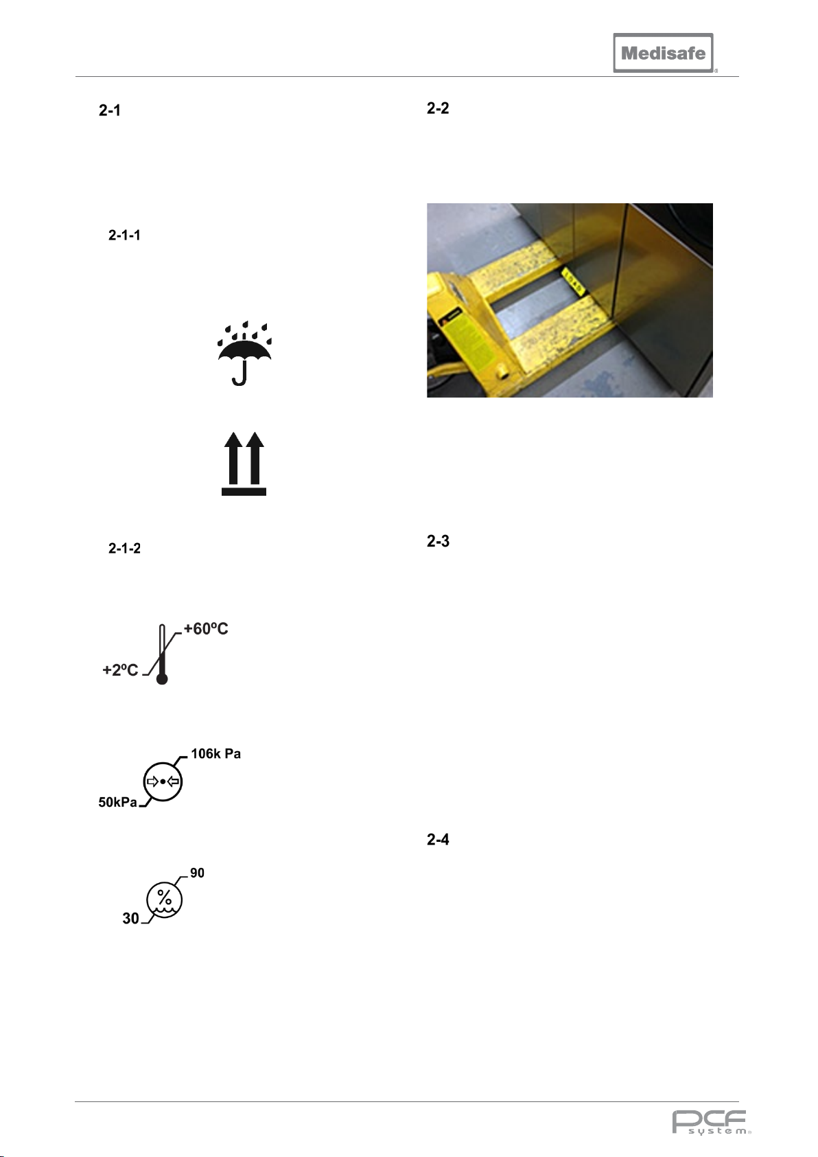
Marking
The markings on the packing crate stipulate the
machine’s storage conditions and handling
information.
Keep dry
This way up’
Environmental
This equipment can be transported and stored
safely, in the following environment:
Temperature Range:
+2°C to +60°C
50kPa to 106kPa
Pressure range
Humidity range
30% to 90% RH
(Non-condensing)
Lifting
Lifting and manoeuvring the PCF Pro in its
packing crate must be done using a pallet truck
or forklift truck able to take a load in excess of
550kg. Ensure that the forks are evenly spaced,
and central to the machine as shown:
Beware: The Load pedal and drain outlet is
vulnerable at this stage. Care must be taken
not to knock or crush it with the forks, as this
could result in irreparable damage to the drain
and tank assembly.
Unpacking
Retain all packaging materials, if for any reason
the unit needs to be returned to the supplier,
then the original crate and packaging materials
should be re-used.
Carefully unpack your PCF Pro by removing the
top panel first. The front panel of the packing
crate is designed to be used as a ramp to aid in
getting the machine off the crate. Once off its
base and unpacked, it can then be moved
across a level floor on its castors.
This equipment is not intended to be routinely
moved, wheels are provided only to facilitate
installation and servicing by a service engineer.
Returns
Before transporting a used PCF Pro, it is vital
that all fluid is thoroughly drained from the
machine. If returning the unit to your supplier or
Medisafe UK Ltd it MUST first be fully
decontaminated before transporting.
The Decontamination Certificate must also be
completed and displayed in a prominent
position when returned with the product (see
section 3-14-4).
DOC01851 Page 20 of 74
Page 21
PCF Pro User Manual
Enclosures Check List
The unit is supplied with a range of accessories to enable easy installation and efficient operation.
Ensure that all these items are present before attempting to install or operate the unit. Complete the
following Enclosures Check List and notify your supplier of any shortages or damaged components as
soon as possible.
The PCF Pro comes with three baskets, instrument tubing, and distal connectors for reverse flushing.
Replacement items can be ordered, see below list for details.
Note: The below depends on your machine type, please refer to what has been specified on your
order.
PCF Pro Accessory Kit (MP21223)
Quantity Part No. Description
1 HOSE002 Standard Washing Machine Hose – Blue
2 HOSE007 Stainless Steel Hose Assembly – Red Indicator
3 MP21225 PCF Pro Plumbing Kit
2 MP21224 Chemical Intake Tube
4 MED8558 Jubilee Clips (50-70mm)
1 MP21006 Elbow Drain Accessory E90-54 (54mm I/D)
1 MP21007 Drain Tube Accessory 54mm O/D x 2mm wall (1m)
1 MP20908 54mm Drain Hose (200mm)
PCF Pro Plumbing Kit (MP21225)
Quantity Part No. Description
2 MED1246.5.0 Distal Connector Box of 10 mixed
20 MP21226 Elbow Hose & Luer (240mm)
Checklist ✔
Checklist ✔
DOC01851 Page 21 of 74
Page 22
PCF Pro User Manual
Additional Accessories
A range of Medisafe approved accessories including replacement parts and consumables, may be
purchased from your supplier. The use of these compatible Medisafe approved products will ensure
the continued and reliable operation of your machine.
Note: Using non-approved chemicals, accessories, and replacement parts may cause damage to the
machine and could void both your warranty and your guarantee of performance.
Printer
Part No. Description
MED1014B Thermal printer including power supply, paper and USA plug
MED1014C Thermal printer including power supply, paper and European plug
MED1014F Thermal printer including power supply, paper and Australian plug
MED1014G Thermal printer including power supply, paper and UK plug
MED1014M Thermal printer including power supply, paper and South Africa plug
MED1014.1 Thermal printer paper (1 x 25m roll)
MED1017
Approved Chemicals
Part No. Description
MED7701 EDA+ 10L Bottle
MED8037 3Ezyme 10L Bottle
Printer Serial Data Cable
DB9 Male to Female Straight through
DOC01851 Page 22 of 74
Page 23
PCF Pro User Manual
Machine Position
see
Ambient Lighting
500 Lux minimum room lighting
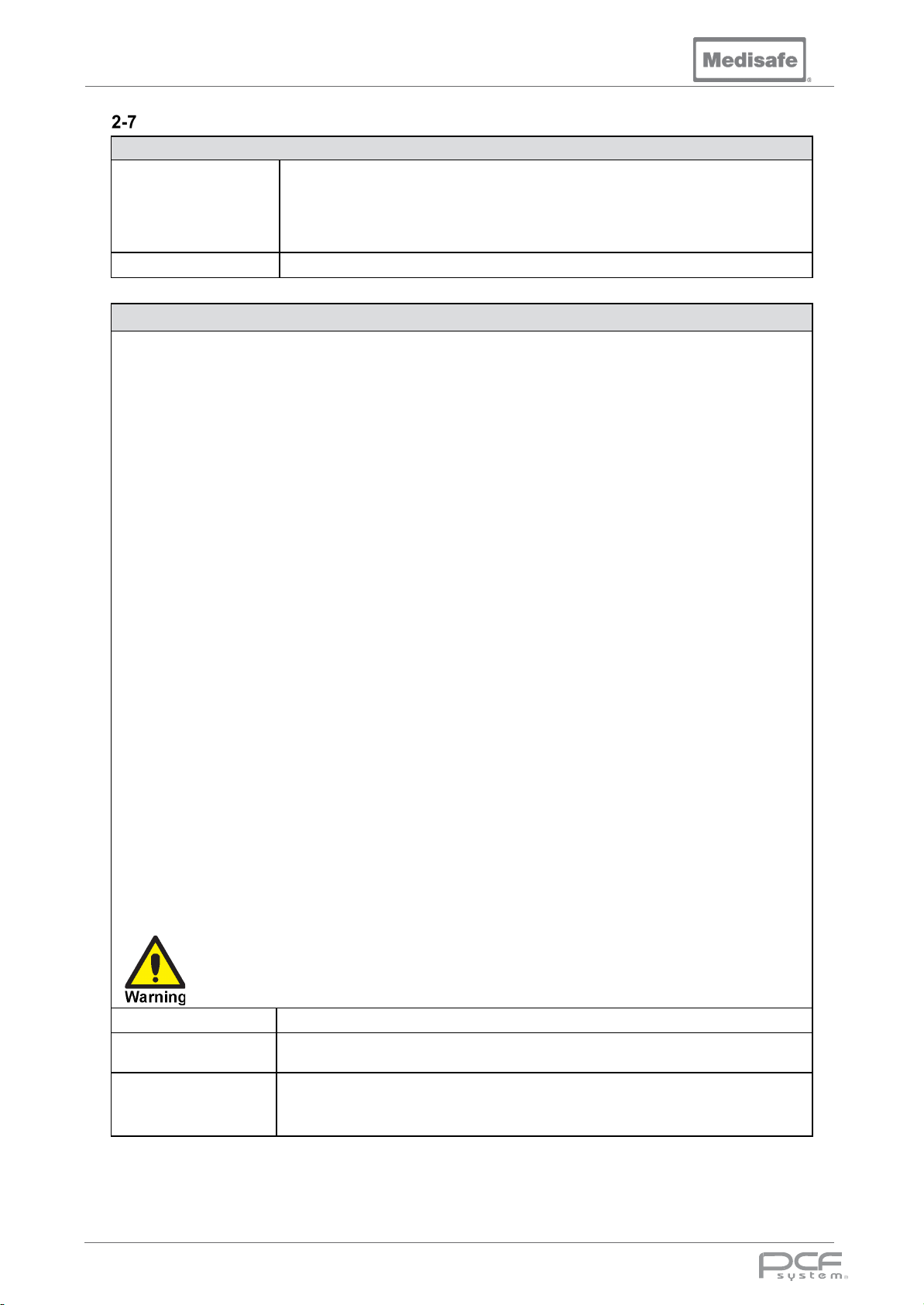
<1.8m from power cable exit. (Rear lower left of unit)
precautions regarding EMC and needs to
Installation Requirements
Level floor and at least 150mm (6in) away from surrounding walls for ventilation (
Site
Mains Supply
Cables shall be rated for maximum current of the equipment, meeting the requirements of IEC 60227 or IEC
60245. The PCF Pro is supplied with 2m of screened power cable.
200 - 230Vac 60Hz Models (only)
Power cable which must be wired using a plug and socket, conductors colour coded as follows:
• Live 1 Black
• Live 2 Black
• Live 3 Black
• Earth Green/Yellow
section 2-9 for dimensions and clearances).
There should be enough free space provided near the machine for safe and efficient
maintenance in the future.
For all Other Models
Power cable must be permanently installed by wiring directly into a switched wall panel. Under no
circumstances should it be wired using a plug and socket. Conductors colour coded as follows:
• Live 1 Brown
• Live 2 Black
• Live 3 Grey
• Neutral Blue
• Earth Green/Yellow
The cable must be protected with a 3phase Residual Current Device (RCD) and Miniature Current Breaker
(MCB). The RCD and MCB shall only be used to supply this equipment.
The disconnect switch must:
• Isolate all poles simultaneously
• Be lockable in the off position
• Comply with standards IEC/EN 61058-1 and IEC 60447 (creepage and clearances for 4kV transient
voltage)
• Be situated close to the equipment for ease of accessibility, and in a position where the operator can
turn it off in an emergency without leaning over the machine.
• Marked as the disconnection device for this equipment
• Disconnect device off-position should be clearly marked (O) and the on-position should be marked (l)
To avoid risk of electric shock, this equipment must only be connected by a fully qualified
electrician and to a mains supply with a protective earth.
.
Supply Voltage
See section 5-1
Position of supply
Electro Magnetic
Compatibility (EMC)
If >1.8m please advise
Medical electrical equipment needs special
be installed and put into service according to the EMC information provided in the
Appendix
DOC01851 Page 23 of 74
Page 24
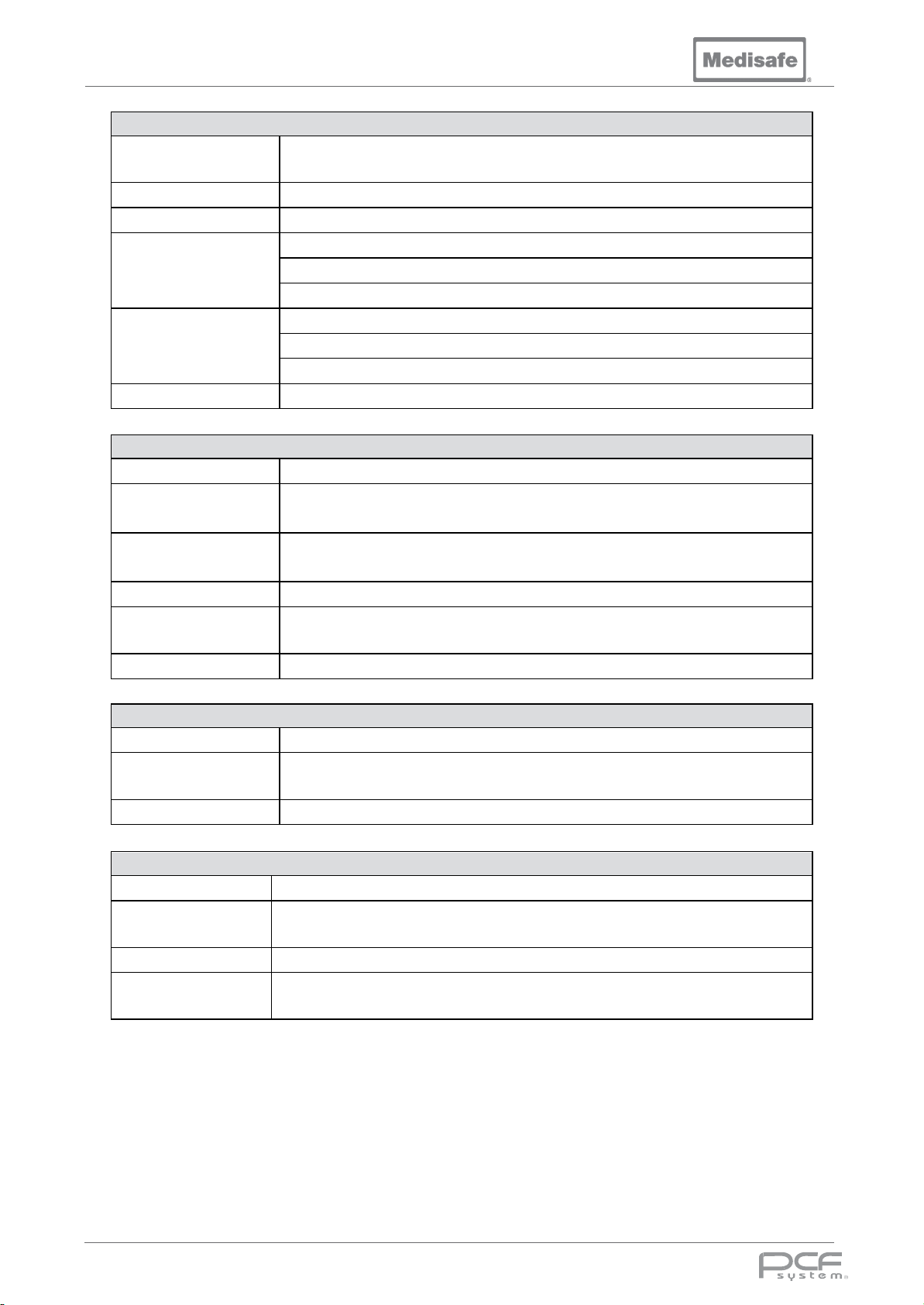
PCF Pro User Manual
Water Supply
Water Hardness
), Quality & Purity
<125ppm with water quality and purity tested and approved for Disinfection as per
Pressure
2 – 5 bar (
) for all water supplies
RO Water 5 – 80°C (
)
1x shut valve with ¾in BSP male thread for hose tail (
)
Position
Within 1m (40in) of proposed installation
Drainage System
Type
Gravity
Drain entry and the entire drain hose must be below the machine drain outlet
Internally connected within the machine to the drain pipe, downstream of the drain
Effluent Temp
95°C (
)
Compressed Air Supply
Pressure
5.5 – 7 bar (80 – 100 psi)
If medical grade compressed air is not used, an Eliminizer needs to be included at
Printer
Position of printer
Within 1m (
) from the machine, where it will not be affected by spillage, leakage
(CaCO
3
Flow Rate 12 – 30 l/m (3 – 8 US gal/m)
Temperature:
Connection
EN ISO15883-1:2009 (item 6.4.1 and 6.4.2)
30 – 70 psi
Cold Water 5 – 30°C (41 – 86°F)
Hot Water 50 – 80°C (122 – 140°F)
41 – 140°F
1x shut valve with ¾in BSP male thread for hose tail (Cold water)
1x shut valve with ¾in BSP male thread for hose tail (RO water)
Drain Connection
Position
Capacity > 180ltr/m (47.5 US gal/m)
54mm (2.125in) OD outlet from machine
Drain must be fitted with suitable traps
Drain gulley pipe ID at least 100mm (4in) to conform with EN ISO15883
Hot water
Overflow
Quality
Connection 8mm (0.315in) dia. Quick fit hose connector
valve
203°F
time of order
Dimensions W:230mm (9in) x D:280mm (11in)
Position
Supply Connection 90 - 230Vac 50/60Hz (single phase).
power supply
Above or to the side and at least within 1m (40in) from the machine, where it will not
be affected by spillage, leakage or condensation from the equipment.
40in
or condensation from the equipment.
DOC01851 Page 24 of 74
Page 25
PCF Pro User Manual
Connecting the PCF Pro
Note: Medisafe (UK) Ltd. recommends this product be installed & commissioned by Medisafe (UK)
Ltd (or suitably qualified personnel).
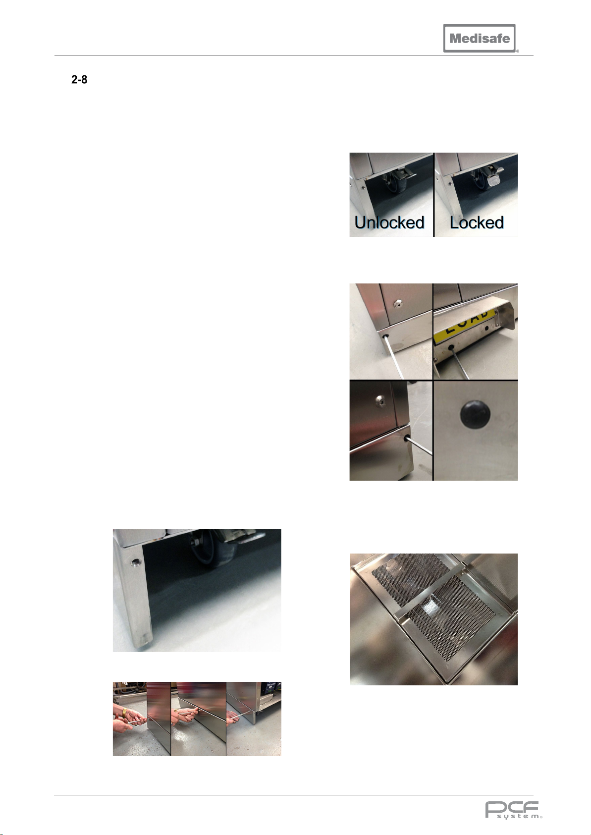
1. Unpack the machine and position it within
1m of the mains power supply, drain, and
mains water supplies.
2. Identify the drain hose supplied with the
unit. Connect the hose to the drain outlet
underneath the right hand side of the unit.
3. Secure the drain hose to the machine
using the supplied jubilee clip, and cut to
length. Refer to the drain connection
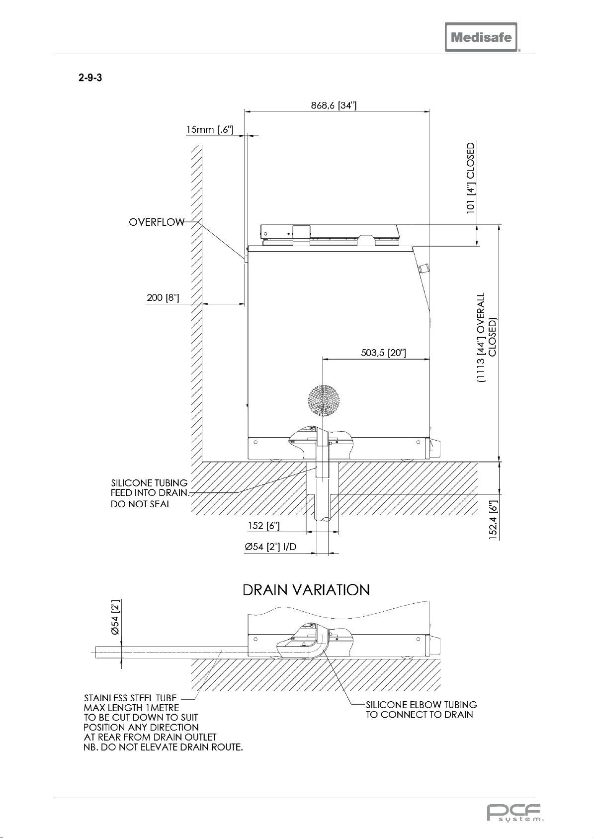
diagram in section 2-9-3 for connection
options.
4. Connect the machine drain to the site
drain.
5. Connect the compressed air hose to the
8mm connector on the lower rear of the
unit.
6. Identify the blue cold-water hose supplied
with the unit. Ensure the seal in the hose
end is in place and screw the elbow
connector onto the cold-water inlet at the
lower rear of the unit.
7. Connect the straight end of the hose to a
suitable cold water supply.
8. Identify a stainless steel water hose
supplied with the unit. Ensure the seal in
the hose end is in place and screw the
elbow connector onto the cold-water inlet
at the lower rear of the unit.
9. Connect the straight end of the hose to a
suitable hot water supply.
10. Repeat for the RO water if this has been
made available on site.
11. Turn on the water supplies and check for
leaks.
12. Fit the shorter of the kick plates to the
machines side, ensuring the nut insert
faces the front of the machine.
14. Move the machine into its final position,
ensuring the castors are aligned front to
back, and apply the front castor brakes
15. Fit the front kick plate over the load switch,
ensuing the switch operates. Screw the
front kick plate to the machine, and fit the
rubber hole covers.
16. Connect the machine to the electrical
mains supply (see section 2-7)
17. Apply power to the machine and open the
lid (see section 3-7-6)
18. Fit the tank filter ensuring it is inserted flat
into the tank recess.
13. Screw the side kick plates to the machine,
and fit the rubber hole covers.
19. Check carrier lift, emergency stop and
20. Carry out the commissioning procedure
DOC01851 Page 25 of 74
safety edge operation (see section 3-7-10)
defined within the PCF Pro Service
Manual.
Page 26
PCF Pro User Manual
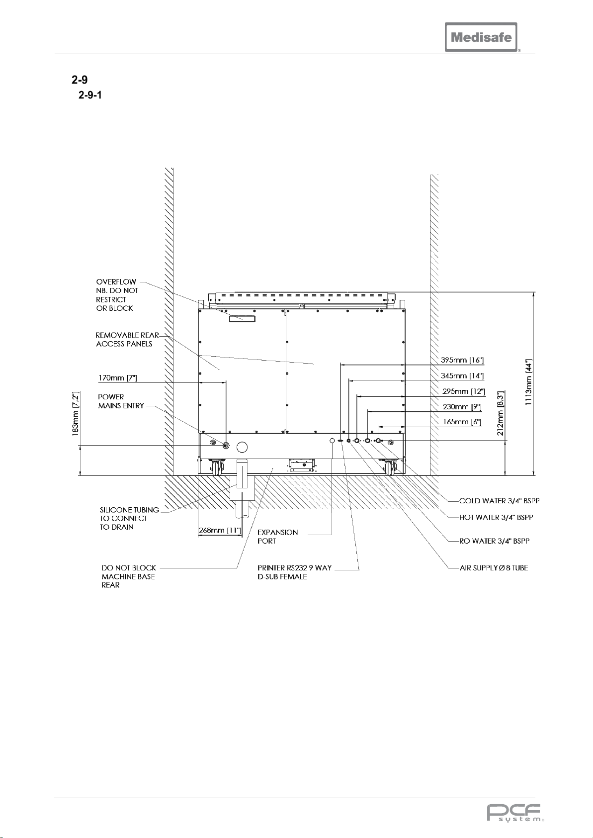
Installation Drawings
Rear View Showing Services
DOC01851 Page 26 of 74
Page 27
PCF Pro User Manual
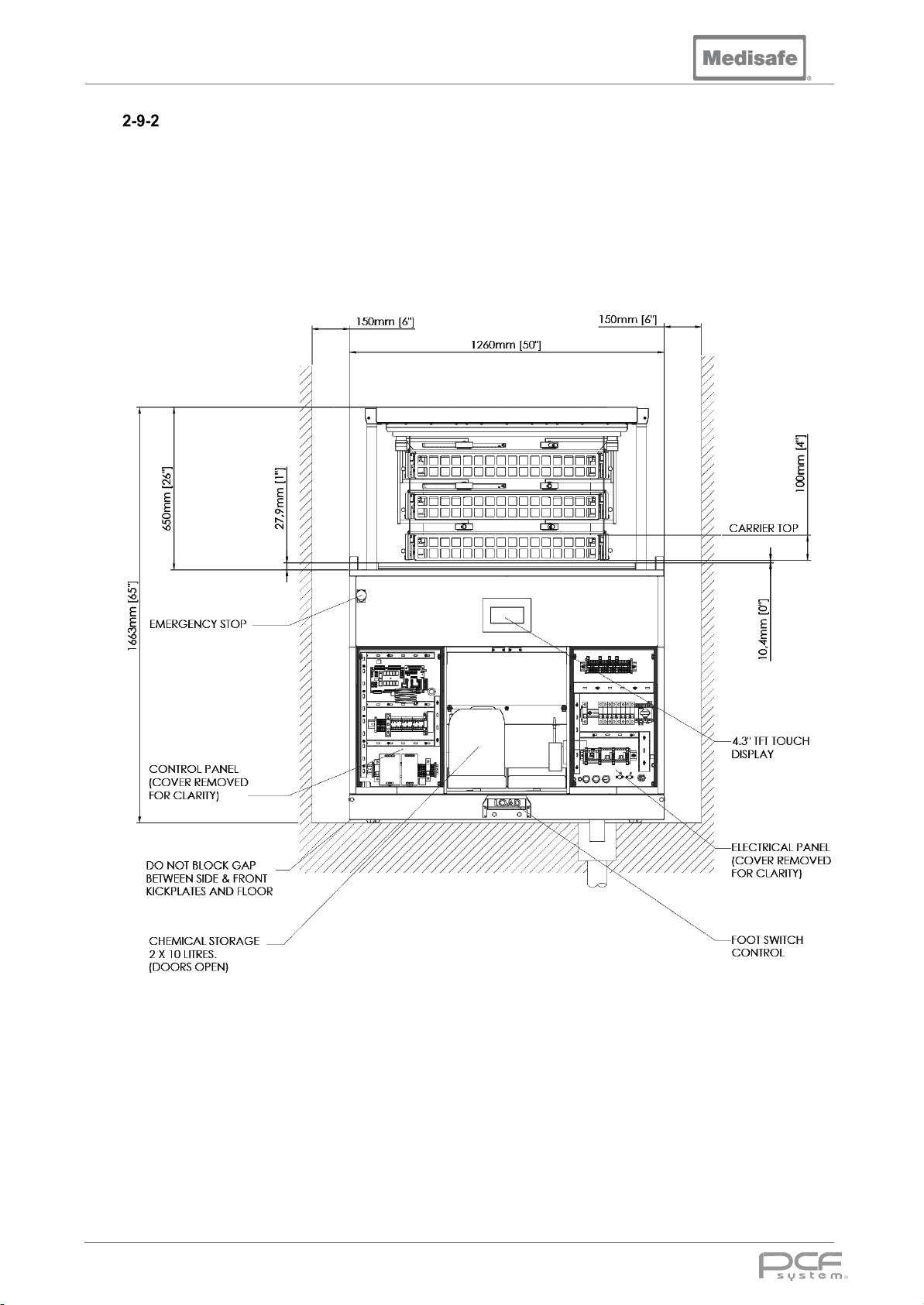
Front View
DOC01851 Page 27 of 74
Page 28
PCF Pro User Manual
Left Side View with Lid Closed showing Drain Connection
DOC01851 Page 28 of 74
Page 29
PCF Pro User Manual
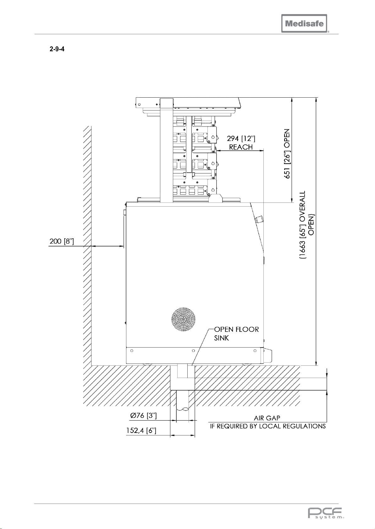
Left Side View Lid Open
DOC01851 Page 29 of 74
Page 30
PCF Pro User Manual
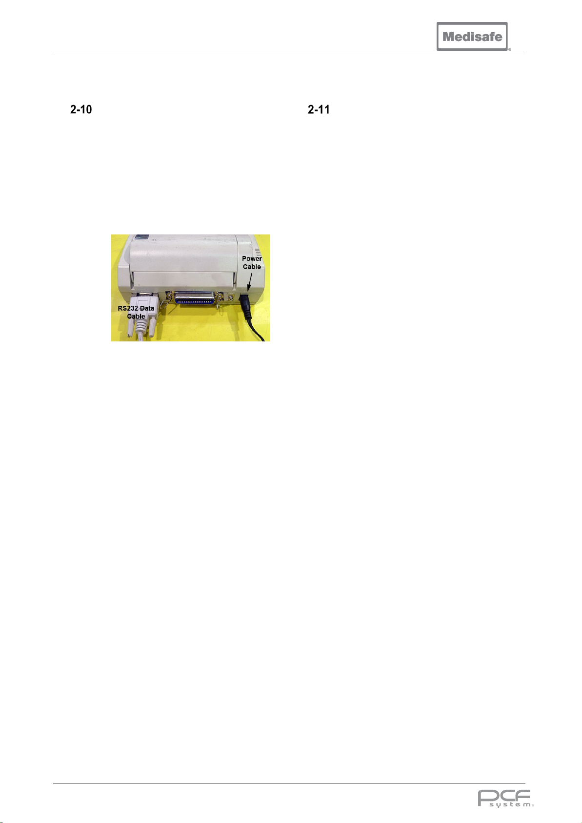
Connecting to the RS232 Port
Thermal Printer
21. Identify the RS232 Data Cable
supplied, and plug the correct end
into the socket located at the lower
right hand side at the rear of the unit.
22. Connect the other end of the RS232
data cable into the connector on the
rear of the thermal printer.
Data Logging PC
Wash cycle data is sent from the serial port to
a printer, however, as an alternative data may
be sent to a logging device or computer via the
serial port using a serial data logging program
of your choice.
Note: Only IEC/EN60950-1 certified
equipment should be connected.
Connect a suitable RS232 Null modem cable
between the data port on the rear panel and a
COM port on your PC. Run your serial data
logging program, ensuring it is configured in
the following manner:
• Baud Rate – 19200bps
23. Plug the printer power supply cable
into the rear socket of the printer,
and connect the mains power cable
into a suitable mains supply outlet,
then switch on the printer.
Note: When the printer paper shows red
stripes, this indicates the paper is about to
runout, and must be replaced. Once the paper
has been changed press the online button, the
green led will illuminate and printing will
resume.
The printer can store more than 10 cycles in
memory when the paper has run out. If the
power is not removed when changing the
paper, the stored cycles will be printed after
the paper has been changed.
• Data Bits – 8
• Parity – none
• Stop Bits – 1
• Flow Control – none
• Handshaking – off
• Buffer size > 500
• Append line feed to cartridge return
DOC01851 Page 30 of 74
Page 31
User Manual
3. Operation
3. Operation
DOC01851 Page 31 of 74
Page 32
PCF Pro User Manual
Menu
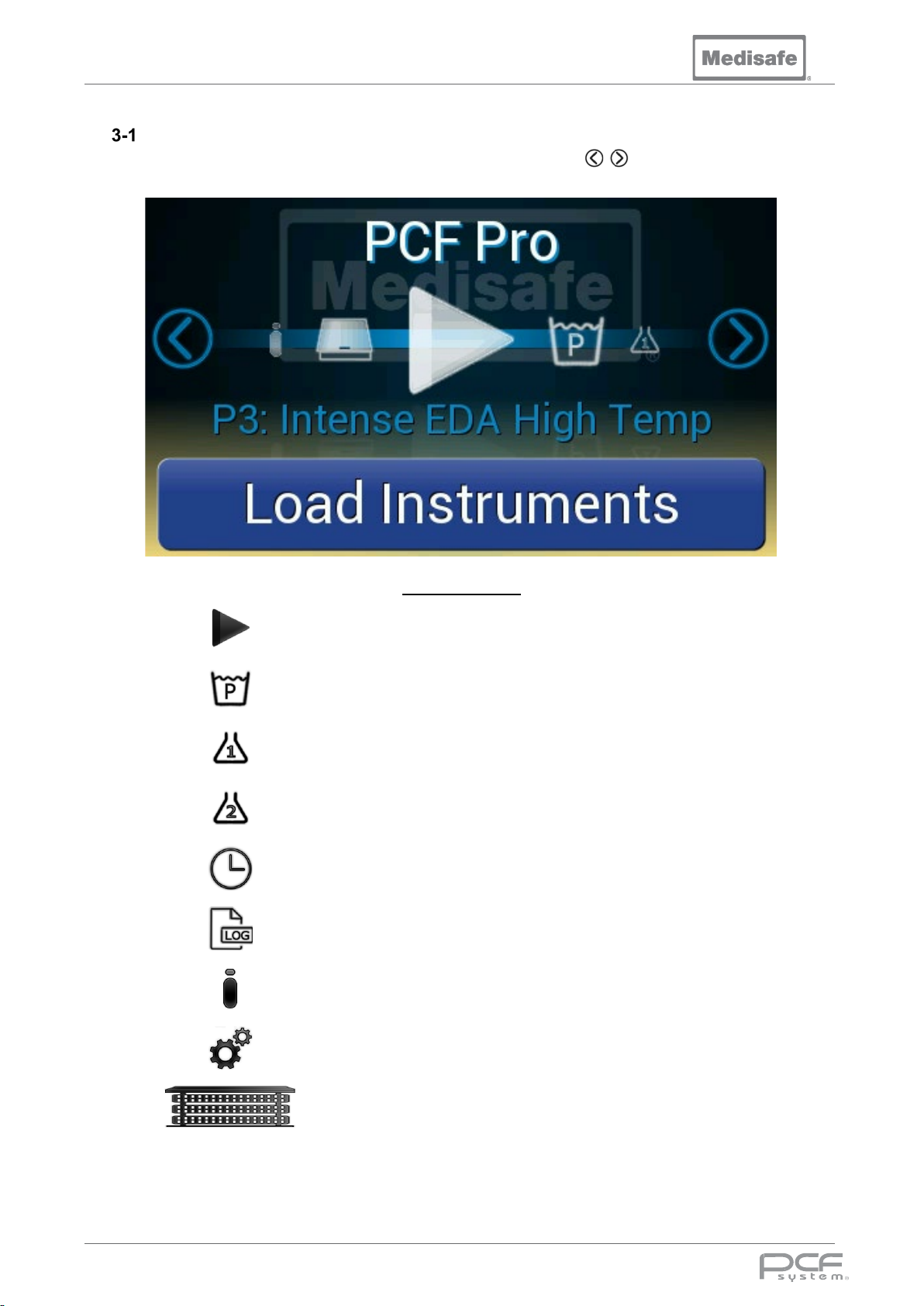
The PCF Pro is controlled using a touch screen menu. The scroll arrows are used to cycle
through the menu pages.
Menu Functions
Start
Wash Program Set the selected wash program
Chemical 1 Prime chemical pump 1
Chemical 2 Prime chemical pump 2
Clock Set the time and date
Data Logging
Information
Start the automated cycle
sequence
Download logged cycle data
onto a USB Flash Drive
Serial number, cycle count and
software version
Supervisor Menu
Carrier
Note: When the PCF Pro has been idle for 10 minutes the screensaver will start, touch the display to
exit.
DOC01851 Page 32 of 74
View and Edit Program
Parameters
Controls to raise and lower the
Carrier Lift
Page 33
PCF Pro User Manual
Power Up
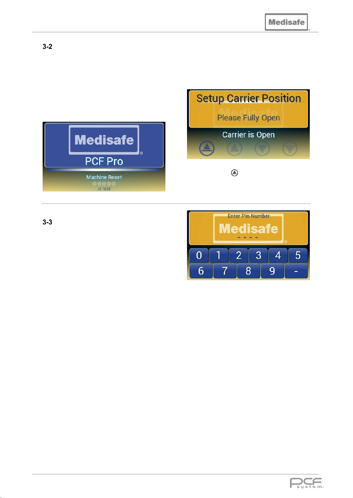
Turn on the power to the machine using the
isolation switch on the wall.
When the machine is turned on, it conducts a
Power-On Self-Test (POST) to ensure the
machine is ready for use.
This process takes a few seconds to configure
the machine and check the basic operation of
the control system, memory and sensor
interfaces.
Authorisation code
This is an optional feature, which can be
enabled by a service engineer. When enabled,
the user is required to enter a four-digit PIN
number to unlock the user control panel. A
valid PIN entry identifies the user and their
operator number is shown on the cycle
printout. There are 80 operator numbers each
with a unique PIN number, see Appendix 6-7
for details.
Before the carrier lift system can be used, it
must zero its position sensor. If the machine
was powered off and the carrier lift was not
fully open or closed, then the display will show:
.
Press and hold until the carrier lift is fully
open.
DOC01851 Page 33 of 74
Page 34
PCF Pro User Manual
Setting Time & Date
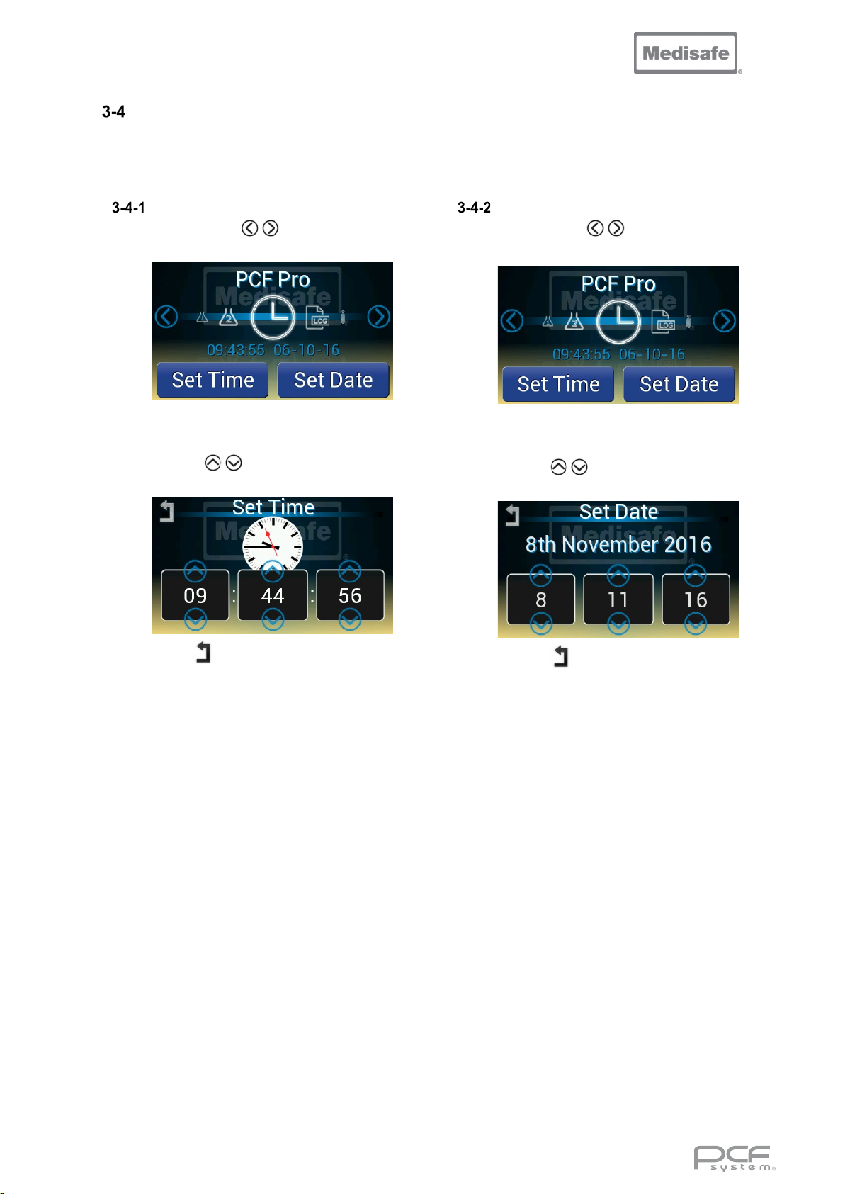
The time and date must be set correctly to ensure the accuracy of the cycle records, and MUST be
periodically checked by the user. There is no automatic provision for daylight saving hours. While the
machine is off, a backup battery maintains the time and date.
Set Time
Set Date
1. Use the scroll arrows to cycle
through to the clock icon
2. Press Set Time
3. Use the arrows to adjust the
Hours, Minutes and Seconds
1. Use the scroll arrows to cycle
through to the clock icon
2. Press Set Date
3. Use the arrows to adjust the
Date, Month and Year
4. Press to return to the main menu
4. Press to return to the main menu
DOC01851 Page 34 of 74
Page 35
PCF Pro User Manual
Express Deluge Wash
da Vinci Wash Cycle
Cannulated Instruments
General
da Vinci Disinfect Cycle
P1
P2
P3
P4
P5
P6
Pre-wash Chemical
ml
190 0 0 0 0 0 Pre-wash Time
Minutes
3 3 3 3 3 3 Wash Chemical 1
ml 0 0
1000
1000
1000
1000
Wash Temperature
ºC 0 0
52
40
52
52
Degas
Minutes
0 0 3 3 3 3 Wash Time
Minutes
0 0 20
10
10
20
Rinse Chemical 1
ml 0 0 0 0 0 0
Rinse Temperature
ºC
60 0 60
60
60
60
Rinse Time
Minutes
2 0 2 1 1
2
Rinses
- 1 0 2 1 2 2
Disinfection Temperature
ºC
0
91 0 91
91
91
Disinfection Time
Minutes
0 3 1 3 3 3 Typical Total Cycle Time
Minutes
21
41
83
87
97
101
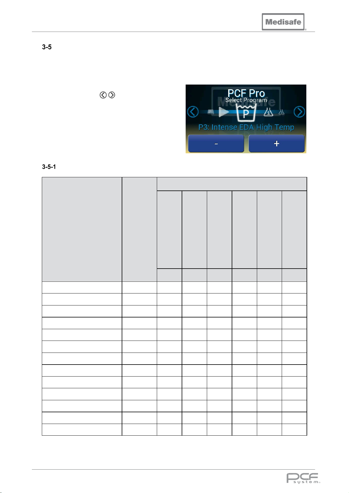
Selecting a program
The PCF Pro is installed with six pre-programmed wash cycles during manufacture. When starting a
cycle, the machine will use the currently selected program. To change the selected program, prior to
initiating a cycle:
1. Use the scroll arrows to cycle
through to the Wash program icon
2. Change the selected program with the
+ and – buttons
Standard Program Parameters
Program Number
Parameters Units
Disinfect Only
Inst. Mild Alkaline
DOC01851 Page 35 of 74
Page 36
PCF Pro User Manual
Caution
Warning
Chemical Handling
Users must read this section prior to any chemical handling.
• Detergents are caustic and can cause adverse effects to exposed tissues. Do not get in
eyes, on skin or attempt to ingest by mouth
• Read and follow precautions and instructions on detergent label and in the Material Safety
Data Sheet (MSDS) prior to handling chemical, refilling chemical containers or servicing
chemical injection pumps and lines
• Wear appropriate Personal Protective Equipment (PPE) whenever handling chemicals or
servicing chemical injection pumps and lines. This should include plastic gloves, goggles
or full-face visor, and disposable plastic apron
• Wear appropriate PPE whenever removing baskets or parts from cleaning chamber
• In case of body contact with chemical, always follow emergency procedure given in that
chemical’s MSDS or call emergency services
• Guidelines to be followed in case of emergency caused by chemical contact should be
prominently displayed near the machine
• Use a funnel when transferring any chemical from one container to another
Chemical Consumption
A 10-litre detergent bottle will give between
eight and eleven washes. The machine weighs
the chemical to detect when there is
insufficient chemical to run a cycle, prompting
the user to replace the bottle before the cycle
begins.
Chemical Replacement
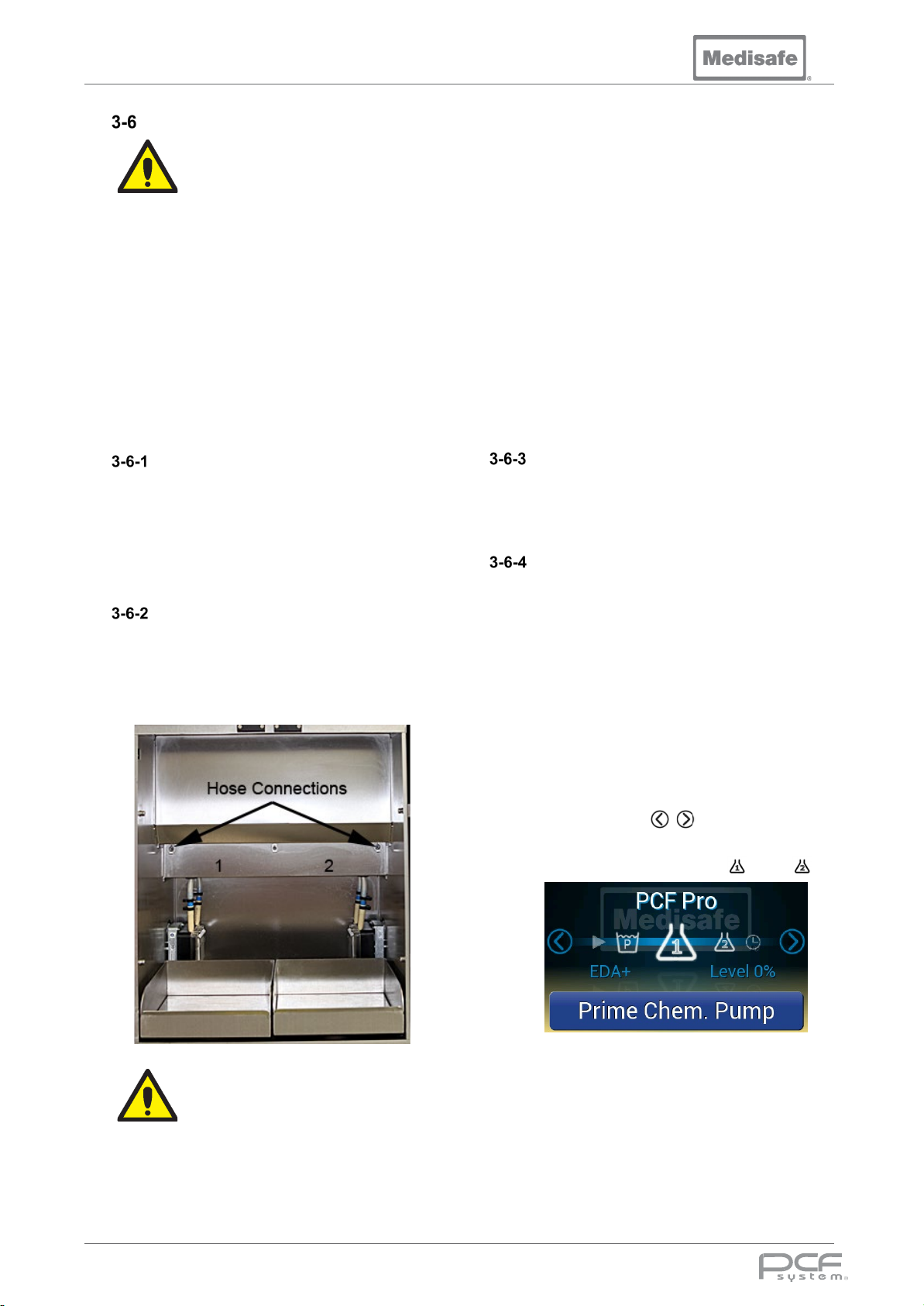
The two centre doors allow access to the
chemical storage compartment, where the
pickup connections are located. The pickup
tube for chemical 1 is on the left, and chemical
2 is on the right.
Disposal of chemical containers
For the correct disposal of chemical
containers, please refer to the manufacturer’s
instructions and local regulations.
Chemical Priming
When changing an empty detergent bottle, to
prevent unnecessary cycle errors the system
should be primed to ensure chemical fills the
entire hose, from the supply to the tank.
1. Remove the empty container
2. Place the new container in the tray
3. Check intake hose filter is clear of
debris
4. Place the intake hose in the container,
ensure any spillages are cleaned up
Chemical bottles must be connected to
the correct port. Otherwise, wash
efficiency and/or rinsing will be
compromised. Ensure that the chemical
type matches the port shown on the
display.
DOC01851 Page 36 of 74
5. Use the scroll arrows to cycle
through to the relevant Prime
Chemical Pump icon or
6. Press Prime Chem. Pump to start the
chemical pump
7. When chemical can be seen entering
the tank, press Prime Chem. Pump
again to stop the pump
Page 37
PCF Pro User Manual
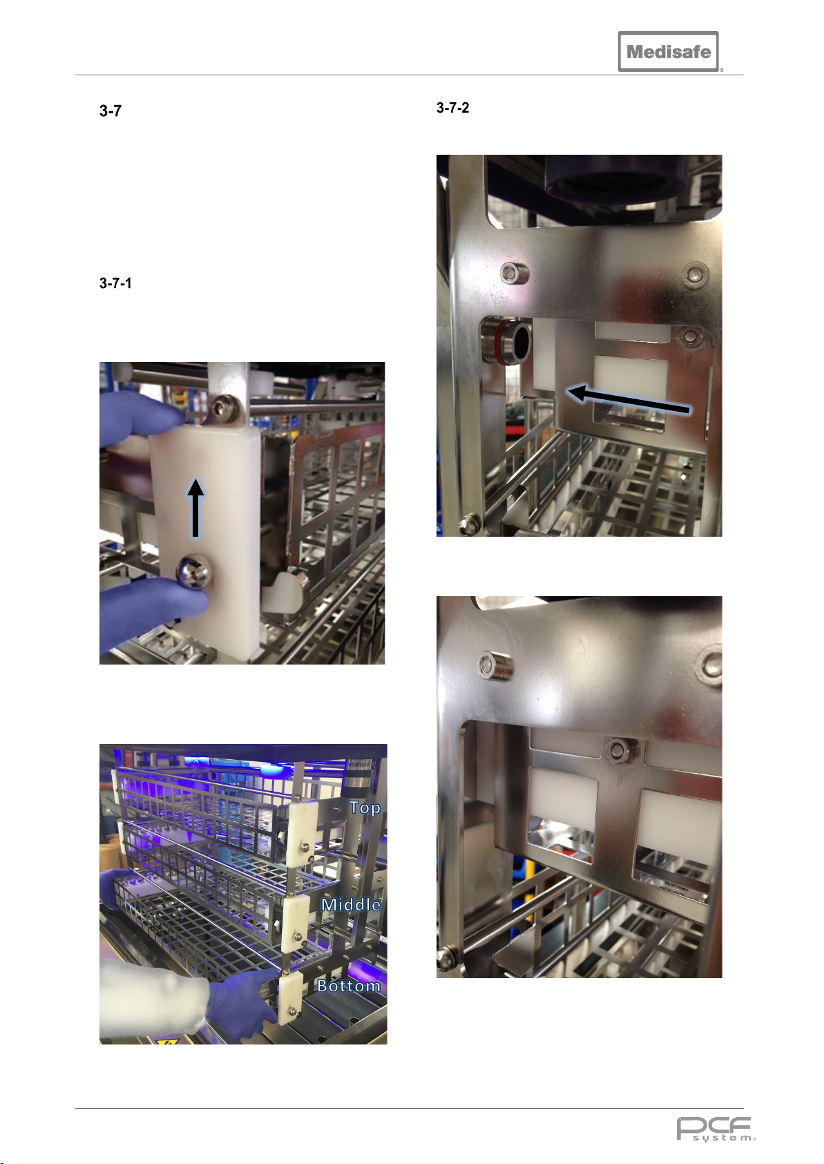
Baskets
The PCF Pro has three baskets, which are
used to house DIN baskets. Easily placed into
and removed from the machine, the baskets
are held in racks on three levels and dock onto
water supply spigots at the rear of the rack. To
prevent the baskets moving during operation
they are locked into position with securing
flags.
Basket Removal
To remove the basket push the thumb ball up
on both sides of the rack. The flags will drop
down allowing the basket to be pulled out of
the rack.
Basket Insertion
To insert the basket, place it on the white
guide rails and push it back
Pull the basket away from the machine, and tilt
down to ensuring any retianed water drips into
the tank.
ENSURE the basket docks onto the irrigation
spigots
DOC01851 Page 37 of 74
Page 38
PCF Pro User Manual
detached from the
during processing, they
should be reprocessed
ensuring that the Luer
Check the condition of
irrigation port Luer
Luer connector
Luer connector clip
Luer pipe
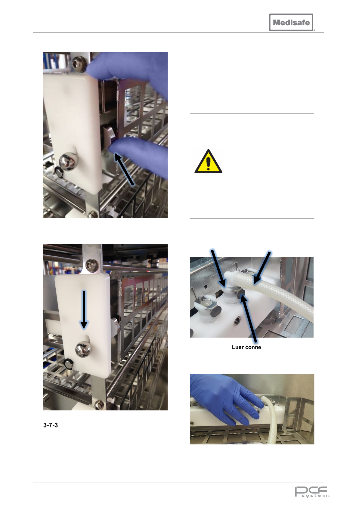
Push up the locking flags
ENSURE the thumb ball latches in the down
position before moving the carrier lift
In general, the luer pipes should be replaced
every 12 months. However, depending on use
of the machine, the luer pipes may require
replacement sooner than 12 months.
The user must inspect the luer pipes before
every use and replace if required.
Note: Replace all luer pipes at the same
time.
• Do not allow Luer pipes to
protrude from the basket.
• If any instruments became
Medisafe connection tubing
Caution
The luer pipe clips into the luer connector.
connection is firmly seated.
•
basket
hoses, ensure they are not
kinked or ruptured.
Luer pipes
The PCF Pro basket comes with luer pipe
connections. Luer pipes are connected to
these connections for cleaning of lumen
instruments.
DOC01851 Page 38 of 74
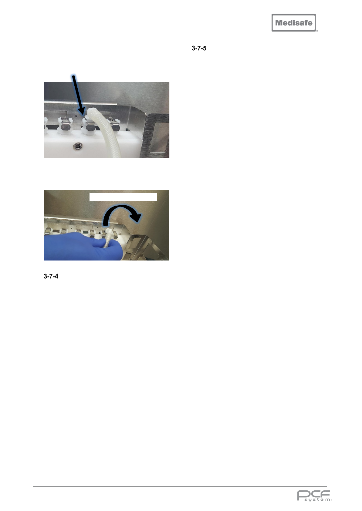
To remove the luer pipe, press the luer
connector clip.
Page 39
PCF Pro User Manual
Luer pipe disconnects
Lift luer pipe to remove
The luer pipe disconnects from the luer
connector as below.
Remove the luer pipe by lifting it away from the
luer connector.
Instrument Loading Precautions
When loading instruments into a basket
observe the following precautions:
• Do not place items directly into the
wash tank or allow them to make
contact with the tank sides.
• Do not load basket with instruments
pointing at the lid.
• Do not overload the basket, maximum
load of 10kg (22lbs) per basket.
• Do not allow Luer pipes to protrude
from the basket.
• Always use a Full DIN Tray Standard
to hold instruments (M20044).
• Always attach tubing to a suitable size
distal connector for instruments being
cleaned or to a quick connect port if
the instrument has one.
• Always open box jointed instruments.
• Always ensure taps are open on
cannulated instruments.
• Always dissemble instruments that
are designed to be taken apart.
Instruments
Each basket is equipped with twenty ports for
maximum pressure irrigation. These are
divided equally between each side to prevent
crossovers or shadowing of instruments.
When selecting Instruments for the PCF Pro:
• Always confirm compatibility with the
instrument manufacturer.
• Always follow the manufacturer’s
instructions if processing instruments
with special characteristics e.g. fibre
optics or rigid optics.
• Whether pre or post processing
instruments, Always follow the
manufacturer’s instructions.
DOC01851 Page 39 of 74
Page 40
PCF Pro User Manual
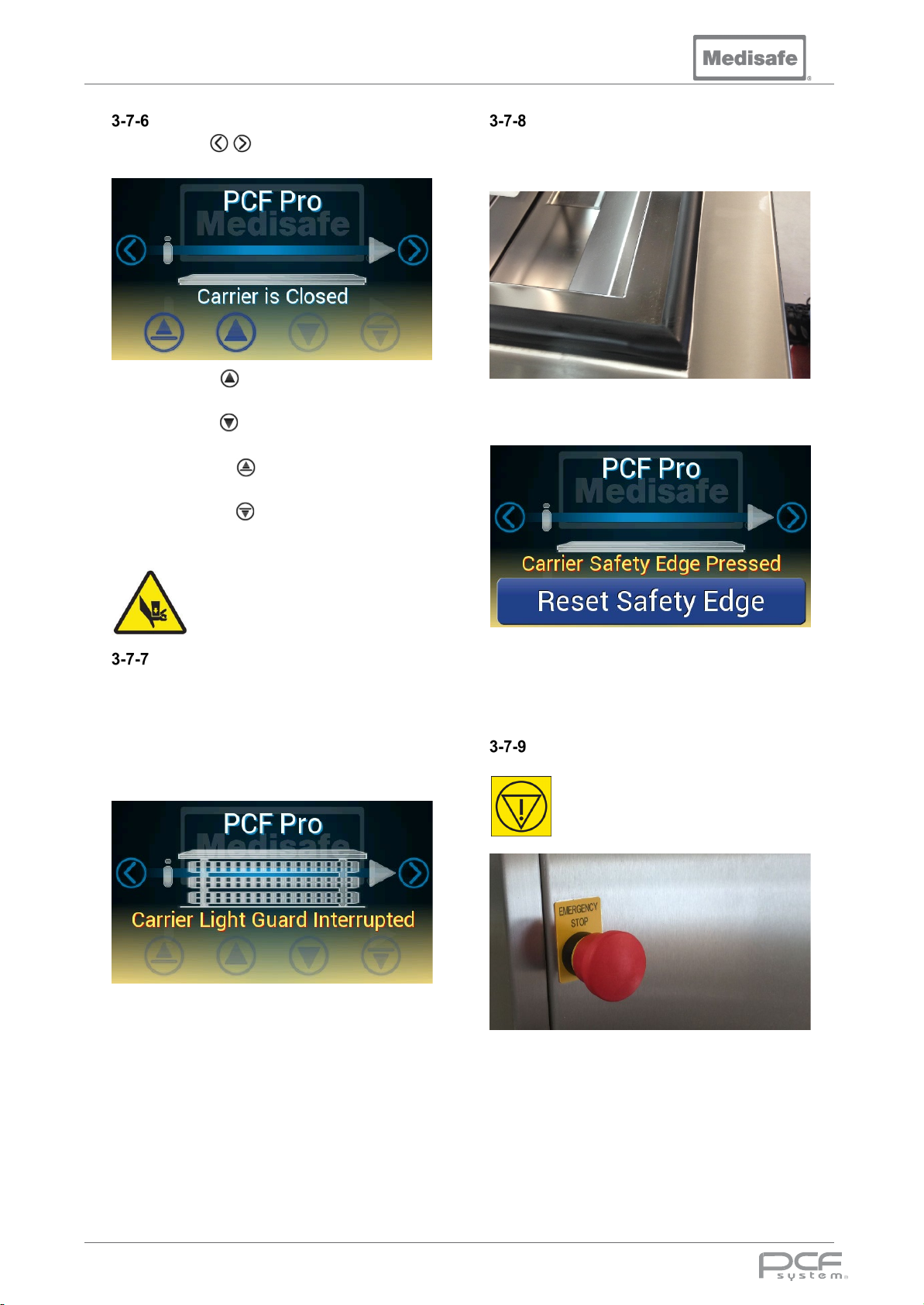
Carrier Lift Controls
Use the scroll arrows to cycle through to
the carrier lift icon.
Press and hold to index the carrier lift up to
the next level
Press and hold to index the carrier lift down
to the next level
Press and hold to open the carrier lift
without stopping at each level
Press and hold to close the carrier lift
without stopping at each level
Safety Edge
To protect the operator from crush injury a
Safety Edge pressure activated strip circles
the tank perimeter.
If the safety edge is pressed, the carrier lift will
stop and a message will be displayed:
Pinch points are created during
lid articulation. Keep hands clear
when opening or closing the lid.
Light Guard
To protect against accidental damage of the
baskets and Lifting system, a light beam
sensor monitors for obstruction along the front
of the Carrier Lift. If this beam is broken (i.e by
instruments, baskets or basket flags) the
carrier lift will stop and a message will be
displayed:
Note: If the Carrier Lift was travelling down
when a fault is detected, to release an
obstruction it will stop, reverse, travel up a few
centimetres and stop.
Once the obstruction is removed from the light
guard path, the machine will allow the Carrier
Lift to be operated again.
To allow the Carrier Lift to be operated again,
remove the obstruction and press Reset
Safety Edge on the display.
Emergency Stop
In the unlikely event of an
uncontrolled fault, the emergency
stop button can be pushed to cut
power to the Carrier Lift and other
critical outputs.
When the emergency stop is pressed, the
machine will display an error message and
abort a cycle if one was running (see section
3-9-10). Normal operation can only be
resumed once the emergency stop button has
been pulled out.
DOC01851 Page 40 of 74
Page 41
PCF Pro User Manual
Testing Operation of the Safety Devices
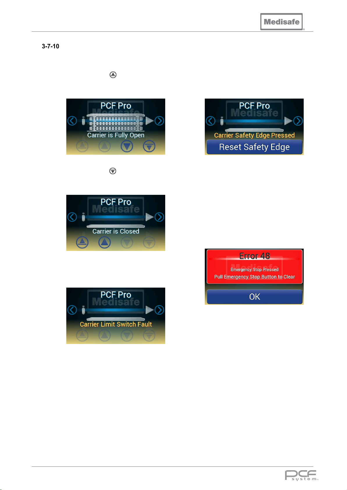
To check operation of the carrier lift:
1. Press and hold to fully open the
carrier lift and confirm the display
shows:
To check operation of the safety edge:
1. While moving the carrier press the
safety edge and confirm the carrier lift
stops and the display shows:
2. Press and hold to fully close the
carrier lift and confirm the display
shows:
3. If the carrier lift system encounters a
problem it will be shown on the
display:
4. If a carrier limit fault message is
shown please contact Medisafe to
resolve the fault.
2. Press Reset Safety Edge on the
display and confirm the carrier lift can
be moved again.
To check operation of the emergency stop:
1. While moving the carrier lift press the
emergency stop and confirm the
carrier lift stops and the display shows:
2. Pull out the emergency stop button
then press OK on the display, and
confirm the carrier lift can be moved
again.
DOC01851 Page 41 of 74
Page 42
PCF Pro User Manual
Starting a Cycle
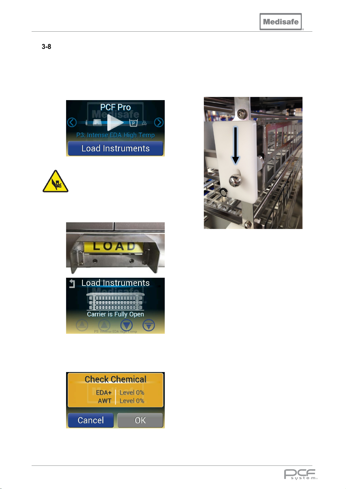
The load sequence is optimised for hands free
operation using the Load foot pedal to step
through an automated sequence:
1. Confirm program selection (to
change see section 3-5)
Pinch points are created during lid
articulation. Keep hands clear
when opening or closing the lid.
2. Press and hold the Load foot pedal
until the carrier lift is fully open
Replace chemical(s) (see section 36-2) and press OK to continue, or
press Cancel to abort the cycle start
3. Insert the bottom basket into machine
and latch (see section 3-7-2)
If there is insufficient chemical to
complete the cycle a warning will be
shown:
4. Press and hold the Load foot pedal
until the carrier lift indexes down to the
next level and stops
5. Insert the middle basket into machine
and latch (see section 3-7-2)
6. Press and hold the Load foot pedal
until the carrier lift indexes down to the
next level and stops
7. Insert the top basket into machine and
latch (see section 3-7-2)
8. Press and hold the Load foot pedal
until the carrier lift is closed, and the
cycle will start
Note: the touch screen controls may be used
to bypass the automated sequence (see
section 3-7-6)
DOC01851 Page 42 of 74
Page 43
PCF Pro User Manual
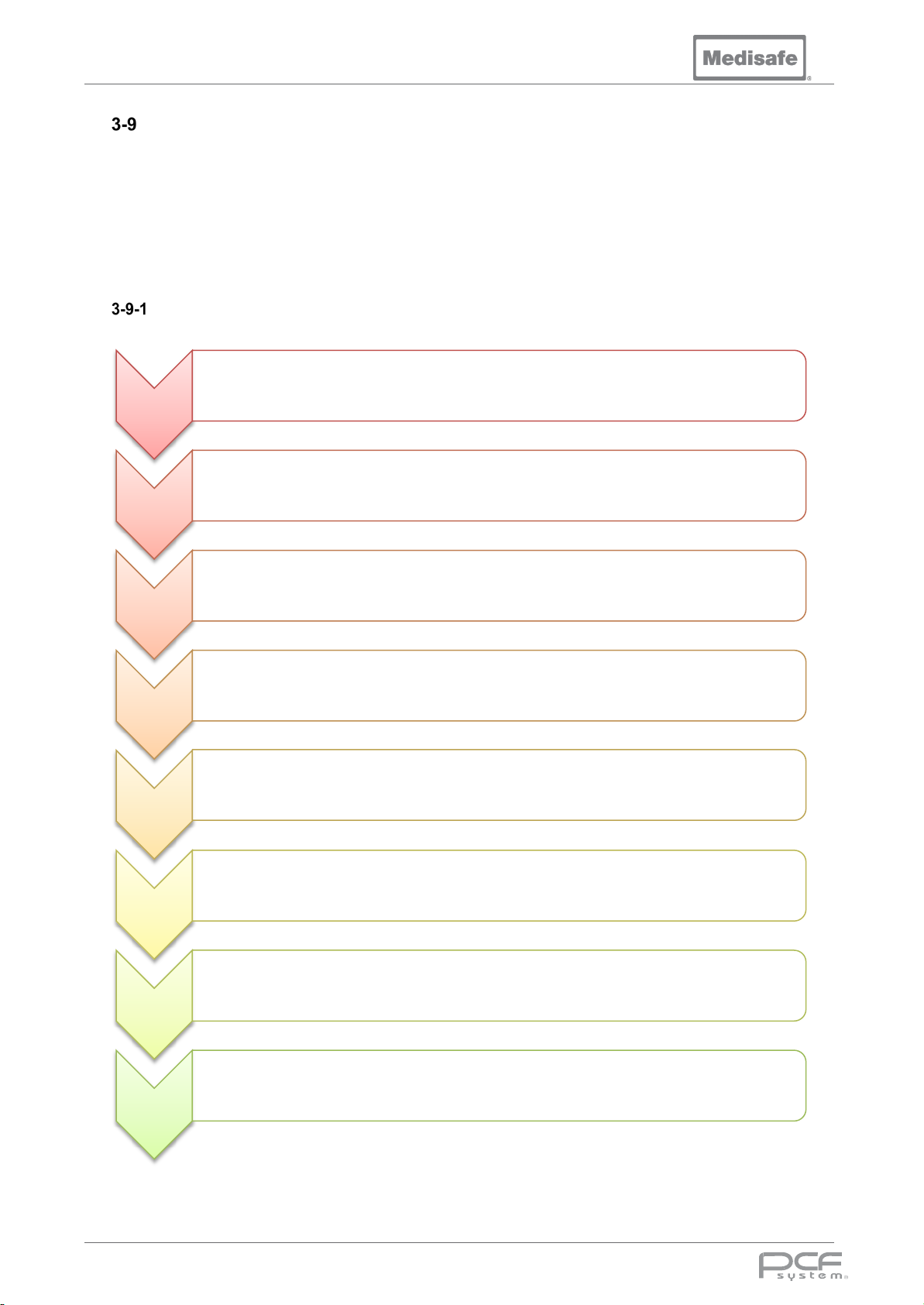
Automated Wash Cycle
The automated wash cycle consists of the stages Pre-wash, Wash, Rinse, Final Rinse/Disinfection,
Cooling and Drying. Every stage of the cycle is configured by the Program Parameters stored in the
machines memory (see section 3-5-1). These parameters allow the cycle to be customised to select
the fill water type, skip stages, repeat stages, control temperature set points, set stage duration etc.
During a cycle, the remaining time for each stage will be shown on the right hand side of the display,
and the temperature/pump pressure on the left.
Cycle Process
• Lock Lid The lid is sealed shut to prevent entry during the cycle
Start Cycle
• Fill Fill tank with cold water to the minimum level
• Cyclin g For a set pe riod alternate between spray arms (45s) and lumen flushing (15s), heating up to 35°C
Pre-wash
• Drain Drain until tank is empty, then for a further 20s
Wash
Rinse
Final Rinse /
Disinfection
Cooling
Drying
• Fill Fill tank with cold and hot water mix up to the top level
• Dose Detergent is added once the mini mum tank level is reached
• Heat Heat water to the set point, circulating through the lumens and spray arms
• Degas Pulse ultrasonics on and off for the degas period, with no recirculation
• Cyclin g Alternate between ultrasonics (45s) and lumen flushing (15s) for a set period
• Drain Drain until the tank is empty, then for a further 20s
• Fill Fill tank with Hot water upto the minimum level
• Cyclin g For a set pe riod alternate between spray arms (45s) and lumen flushing (15s), heating up to the set point
• Drain Drain until the tank is empty, then for a further 20s
• Fill Fill tank with Hot/RO water upto the minimum level
• Heat Heat water to the set point, circulating through the lumens and spray arms
• Cyclin g For a set period circulate through the lum ens and lid spray
• Drain Drain until the tank is empty, then for a further 20s
• Fill Add cold or RO water run down the back of the tank up to the bottom level
• Drain Continuouslydrai n the tank throughout
• Repeat Repeat the cooling process until cham ber temperature below 60°C
• Drain Drain until the tank is empty, then for a further 20s
• Soft -shot For a set period compressed air is alternately blown through the irrigation ports and spray arms
Cycle
• Confir m Acknowledge cycle complete by pressing unload on the display
Complete
DOC01851 Page 43 of 74
Page 44
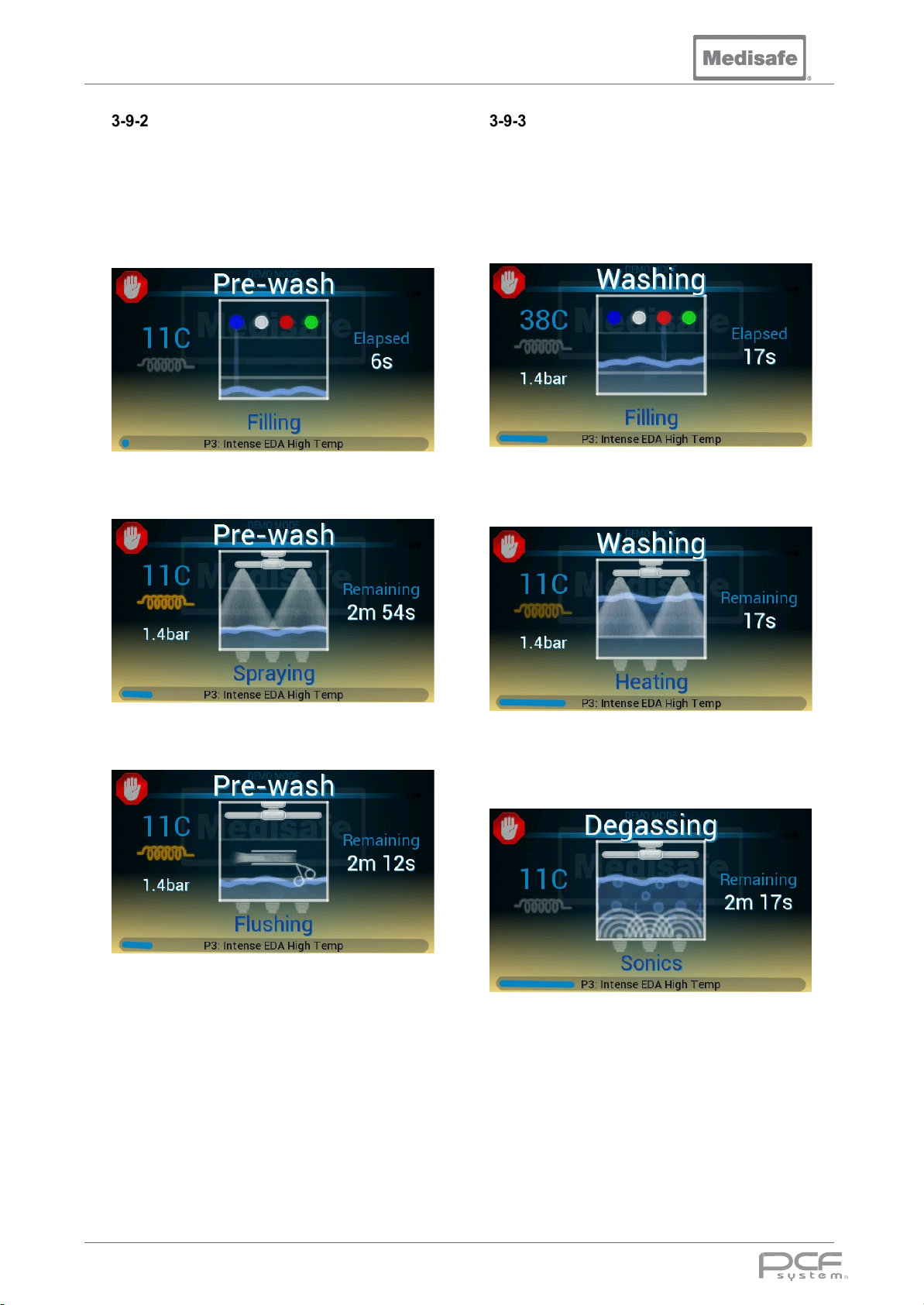
PCF Pro User Manual
Pre-wash
All water in the tank is drained. The machine
fills with cold water to the minimum level.
During filling for each stage, the spray and
irrigation valves are opened, and the pump is
operated at least once to ensure all voids are
filled.
The machine then washes for a set time,
alternating between spraying and flushing.
Wash
The tank is filled to the top level with a mix of
hot and cold water to attain the set
temperature. Once the water reaches the midlevel, a quantity of detergent is dispensed into
the tank. The pump is pulsed on and off to
even out the temperature, fill all cavities, and
to mix the chemical thoroughly.
Once the tank is full, if the temperature is
below the set point, the water heater will turn
on.
During flushing recirculated water is pumped
through the instruments.
Finally, all water in the tank is drained
When the set temperature is reached, the
ultrasonics degas the tank by pulsing on and
off for a pre-defined time to remove any
dissolved air.
At the end of the degas period the machine will
then alternate between irrigation and
Ultrasonics for a pre-defined time.
DOC01851 Page 44 of 74
Page 45
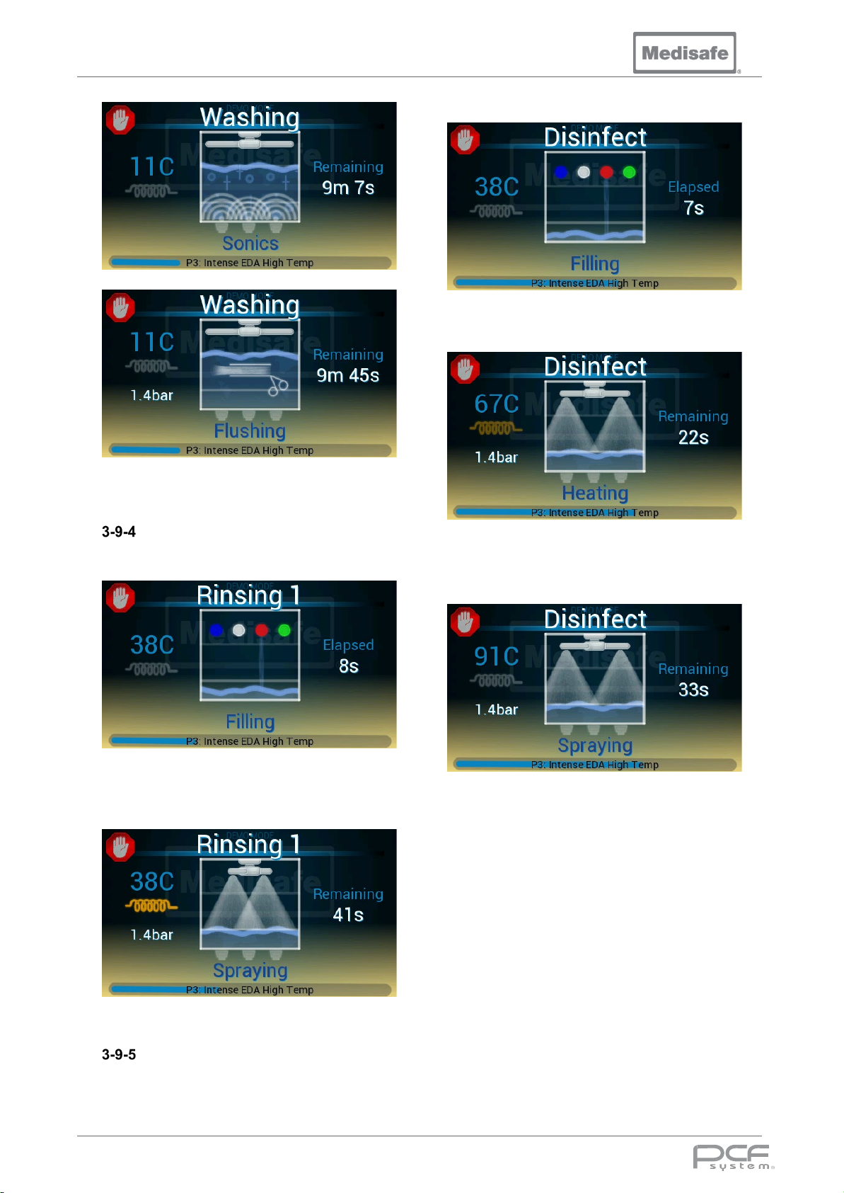
PCF Pro User Manual
Finally, all water in the tank is drained.
Rinse
The machine fills with hot water to the
minimum level.
to the minimum level.
Once the tank is filled, the water heater will
turn on to heat the water to the set point.
When the set point is reached, the machine
will alternate between Flushing and Spraying
for a pre-defined time.
The machine will alternate between Flushing
and Spraying for a pre-defined time while
heating the water up to the temperature set
point.
Finally, all water in the tank is drained.
Final Rinse/Disinfection
The machine fills with hot water (or RO if fitted)
Finally, all water in the tank is drained.
DOC01851 Page 45 of 74
Page 46
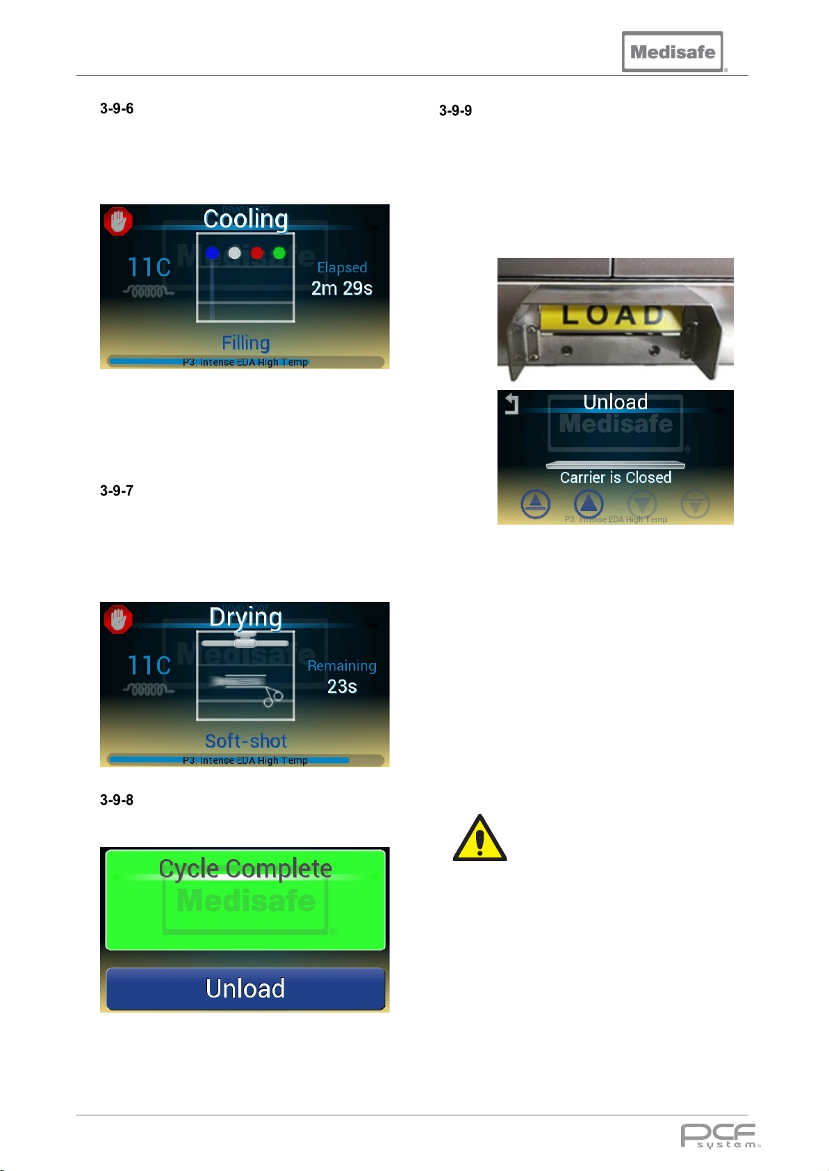
PCF Pro User Manual
Caution
Cooling
On completion of the last cleaning stage, the
inside of the machine will be hot. To reduce
the water vapour and temperature, cold water
is cascaded down the back wall of the tank
and into the drain a pre-defined time.
Note: this water does not come into contact
with the load.
Finally, all water in the tank is drained.
Drying
To aid the drying of cannulated instruments
and to remove excess water from manifolds
and pipework, compressed air is alternately
blown through the irrigation ports and spray
arms. This minimises spillage when the
baskets are removed from the machine.
Cycle Complete
When the cycle is complete, a sound is played
and the LED Edge flashes green.
Confirm cycle record is present and indicates
the cycle has completed with no errors.
Unload
The unload sequence is optimised for hands
free operation, where the Load foot pedal is
used to step through an automated sequence:
1. Press and hold the Load foot pedal
until the carrier lift indexes up to the
bottom basket and stops
2. Remove the top basket from the
machine (see section 3-7-1)
3. Press and hold the Load foot pedal
until the carrier lift indexes up to the
next level and stops
4. Remove the middle basket from the
machine (see section 3-7-1)
5. Press and hold the Load foot pedal
until the carrier lift indexes up to the
next level and stops
6. Remove the bottom basket from the
machine (see section 3-7-1)
If any instruments became
detached from the Medisafe
connection tubing during
processing, they should be
reprocessed ensuring that the
Luer connection is firmly seated.
7. The machine is now ready for the next
cycle
Note: the touch screen controls may be used
to bypass the automated sequence (see
section 3-7-6)
DOC01851 Page 46 of 74
Page 47
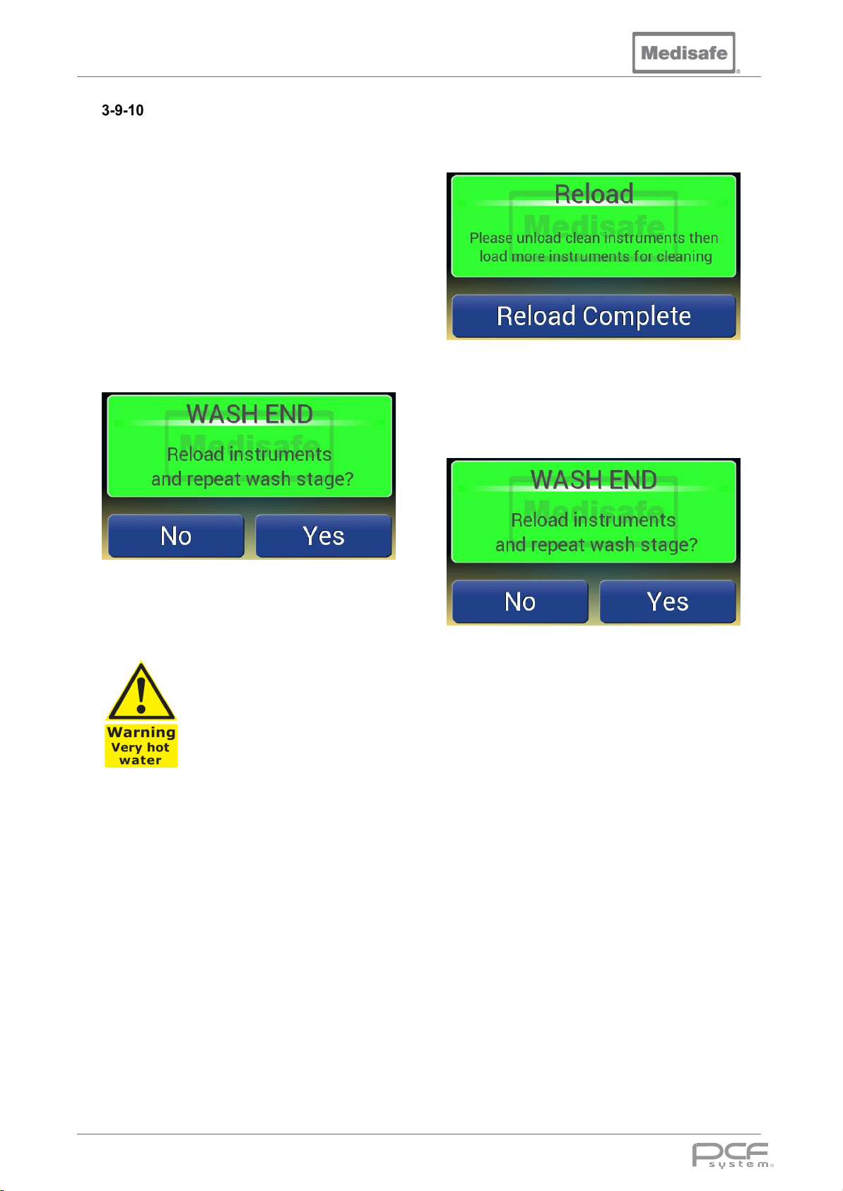
PCF Pro User Manual
Re-Wash Cycle
The PCF pro can be configured with a re-wash
program - a water and time saving feature.
This allows the wash water and chemical to be
reused. At the end of the wash, the user is
allowed to open the lid, add new instruments,
and repeat the wash stage using the same
water up to ten times.
Note: if the water temperature exceeds the set
point by more than 10°C the cycle will be
aborted (see section 3-9-10).
At the end of a wash stage press Yes on the
screen to reuse the water again.
Press Reload Complete on the screen to
begin another wash stage
To end the re-wash process, once the wash
stage is complete press No on the screen to
drain the water and end the cycle.
Unload the instruments (see section 3-9-9)
then load more instruments for cleaning (see
section 3-8).
Temperature of the water within
the unit can reach 60°C
(140°F), when opening the lid
and reloading instruments take
care and wear appropriate PPE.
DOC01851 Page 47 of 74
Page 48
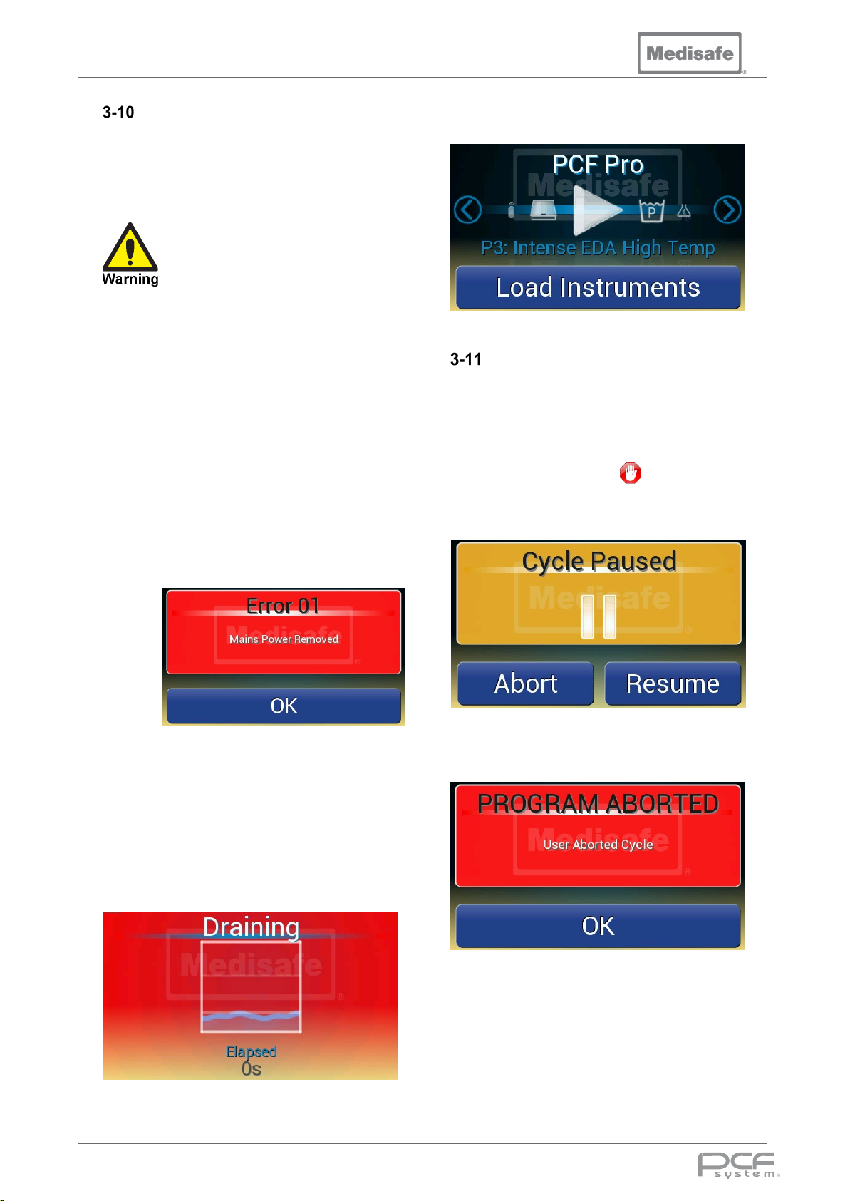
PCF Pro User Manual
Cycle Errors
If an unexpected condition occurs during a
wash cycle (i.e. low pump pressure, low water
temperature, see section 4-1 for a full list) the
system will abort the cycle and report an error.
When an error occurs during a
cycle the load may still be
contaminated, and will still require
processing. Check the printout to
see if the cycle completed before
the error, if it did not then repeat
the cycle to attempt to reprocess
the load. If the error persists use
another machine or alternative
cleaning and disinfection process
(according to facility procedure),
then contact a service engineer to
repair the machine.
If an error occurs:
• An audible alarm will sound
• The LED Edge will flash red (see
section 3-12)
Once the tank is drained, the machine will be
reset and return to the main menu.
Aborting a Cycle
While running a cycle in the PCF Pro, it may
be necessary to end (abort) the cycle
operation before scheduled completion,
because of a unit problem, wrong load, etc.
To abort a c ycle press in the top left
corner. This will pause the cycle, press Abort
to confirm or press Resume to continue the
cycle.
• An error code and description will be
shown on the display:
• The printer will output the Error code,
description, and diagnostic
information
Acknowledge the error by pressing OK.
If the tank is not empty, the water will be
automatically drained to allow access to the
load.
If the cycle is aborted, a cycle error will be
generated (see section 3-9-10)
DOC01851 Page 48 of 74
Page 49
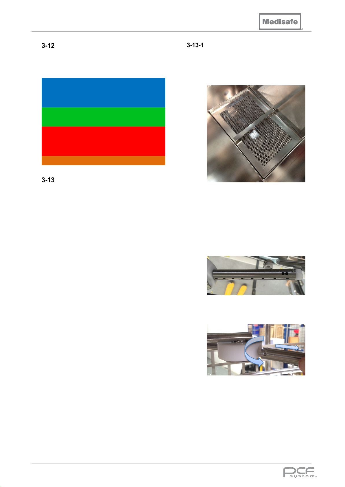
PCF Pro User Manual
LED Edge
The LED Edge colour status indicator on the
lid visually shows the current state of the
machine:
Panning Resetting
Blue
Green
Red
Amber Panning Test Mode
Static Idle
Pulsing Cycle Running
Flashing Cycle End
Static Cycle Completed
Flashing Cycle Halted
Static Error
Panning Carrier Lift Moving
Routine Maintenance
Important safety information:
Always ensure mains power is disconnected.
Always adhere to the recommended safety
precautions for cleaning products in use.
It is recommended that Personal Protection
Equipment (PPE) be worn during
loading/unloading, and cleaning or
decontaminating the equipment. This must
include apron, gloves and eye-protection.
For cleaning internal and external surfaces, a
disinfectant cleaner such as Isopropyl Alcohol
or a household kitchen cleaner can be used,
provided it is marked as a DISINFECTANT
cleaner.
In the interests of health and safety, all
medical washers should be cleaned on a
weekly basis as part of a routine maintenance
program. This will ensure the machine is safe
for operators and maintenance personnel. To
keep your machine operating within its design
parameters the following checks must be
performed on a regular basis. Please note that
completion of these checks is not a substitute
for regular servicing and maintenance by a
suitably qualified engineer.
All maintenance procedures should be carried
out in a well-lit environment, recommended
minimum lighting level is 500Lux.
Before Every Cycle
1. Visually check that there is enough
chemical for the next wash.
Replenish as necessary.
2. Clean the wash tank filter:
Ensure the tank filter is correctly
replaced such that it is inserted flat
into the recess.
3. Check the wash chamber is free from
any debris or deposits.
4. Check the spray arms rotate.
5. Remove each basket and check the
spray arms for blockage:
Remove the spray arm by first
rotating counter clockwise and then
pull.
DOC01851 Page 49 of 74
Page 50
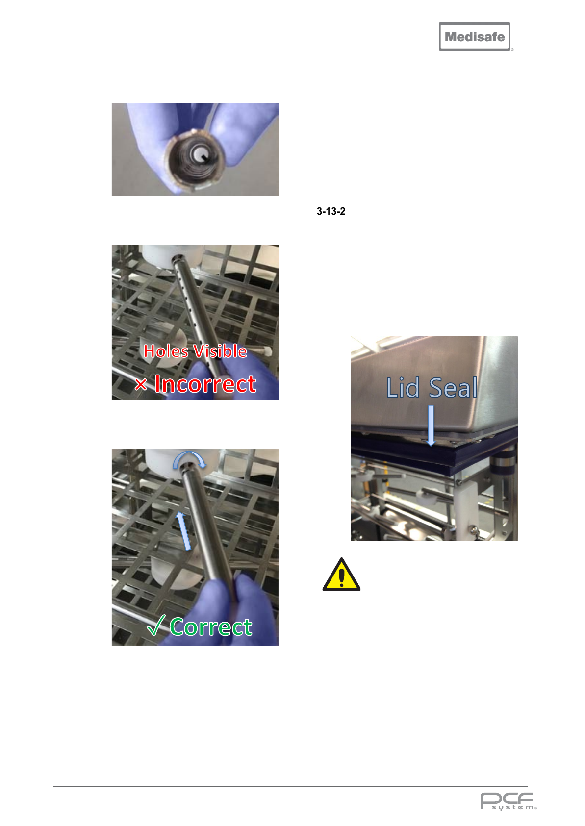
PCF Pro User Manual
Caution
Check inside the spray arm and clear
any debris.
To ensure correct spray direction the
spray arms are handed so they
cannot be inserted incorrectly:
6. Check the condition of basket
irrigation port Luer hoses, ensure
they are not kinked or ruptured.
In accordance to ISO15883, the
international standard for the performance
of Washer-Disinfectors, we advise the
checks stipulated below. However, each
hospital may follow its own checks to
comply with the applicable standards.
Daily Checks
1. Check that there is sufficient
chemical for the days planned use
2. Check and clean all internal surfaces
above the water line.
3. Check and clean all external
surfaces including lid seal.
4. Check lid and lid seal for any
damage.
To replace the spray arm, line up the
slot to the internal hub pin, push in
and then rotate clockwise:
If damage is found, please
contact a service engineer (see
section 1-17).
DOC01851 Page 50 of 74
Page 51
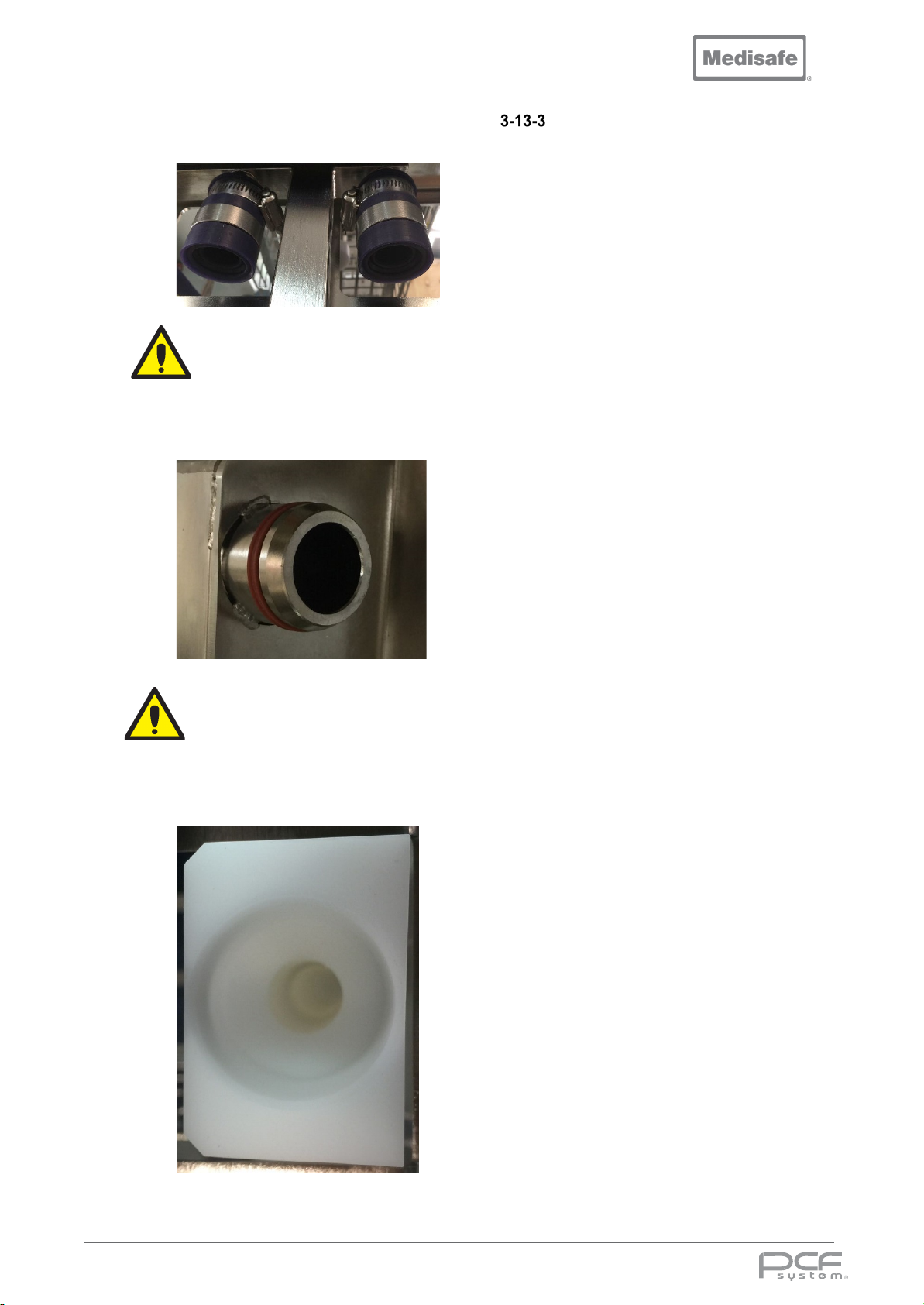
PCF Pro User Manual
Caution
Caution
5. Check the 4 lid docking seals for any
damage.
If damage is found, please
contact a service engineer (see
section 1-17).
6. Check the six basket docking seals
for any damage or debris.
If damage is found, please
contact a service engineer (see
section 1-17).
7. Check the six basket manifolds for
blockage.
Weekly checks
1. Carry out the daily checks.
2. Check water hardness of hot and
cold water supplies.
3. Check water conductivity of final
rinse water supply.
4. Check condition of mains water
Note: The use of a “Process Challenge Device
for Minimally Invasive Surgery” may be
required according to your local authority
guidelines, and the cleaning indicator
manufacturer’s instructions.
Ref:
supply hoses.
5. Visually inspect water and drainage
system for leaks.
6. Cleaning efficacy test by residual soil
detection
7. Run a full decontamination
procedure (see section 3-14).
8. Test operation of safety devices (see
section 3-7-10).
EN ISO15883-1:2009
DOC01851 Page 51 of 74
Page 52
PCF Pro User Manual
Decontamination Guide
Decontamination is defined as the cleaning and disinfection of the machine, and is vital to ensure the
machine is safe for operators and maintenance personnel.
Important safety information:
Always ensure mains power is disconnected.
Always adhere to the recommended safety
precautions for cleaning products in use.
Always work in a well-lit area, recommended
minimum lighting level is 500Lux.
It is recommended that Personal Protection
Equipment (PPE) be worn during
loading/unloading, and cleaning or
decontaminating the equipment. This must
include apron, gloves and eye-protection.
For cleaning internal and external surfaces, a
disinfectant cleaner such as Isopropyl Alcohol
or a household kitchen cleaner can be used,
provided it is marked as a DISINFECTANT
cleaner.
Daily Cleaning/ Procedure
Using a clean cloth or paper towel:
1. Wipe down all internal surfaces
above the waterline with your
disinfectant, including the inside of
the lid and around the seals.
2. Wipe all external surfaces, including
around the sides of the doors.
3. Remove any trace of cleaner from
internal and external surfaces with a
clean wet cloth.
4. Towel dry.
Note: By the nature of its operation, the
washer disinfector’s tank is immersed in water
during the cleaning/disinfection cycle.
Therefore, it should already be clean and
disinfected by the end of a cycle.
Full Decontamination
On a weekly basis:
1. Perform the daily cleaning procedure.
2. Fit luers to all basket ports to ensure
they are open.
3. Run Program 4 (see section 3-5 and
3-8).
If the machine has been idle for more than a
week:
1. Perform the daily cleaning procedure.
2. Fit luers to all basket ports to ensure
they are open.
3. To make a 5% disinfectant solution
place 1.9 litres (typically) of non-
foaming Sodium Hypochlorite based
disinfectant into a shallow heat
resistant container. Place the
container in the basket (this prevents it
from being drained at the start of the
cycle).
4. Select Program 4 (see section 3-5).
5. Start the cycle (see section 3-8).
6. 30 seconds before the Pre-wash stage
finishes, press to pause the cycle.
7. Wait 15 minutes then press Resume
to continue the cycle.
8. Allow the cycle to complete.
Pre Transport Procedure
In the unlikely event of a machine having to be
returned to Medisafe for any reason, the
following procedure must be carried out:
1. Drained and completely empty of fluid.
2. All external hoses removed.
3. Fully decontaminated prior to shipping,
(irrespective of when it was last
cleaned).
4. Accompanied by the relevant signed
Decontamination Certificate (see
section 3-14-4).
Note: If due to the nature of any fault present, the
unit cannot be run prior to return, the tank/chamber
must be decontaminated by hand.
Note: Failure to carry out this procedure will incur
an additional charge for a full decontamination.
DOC01851 Page 52 of 74
Page 53
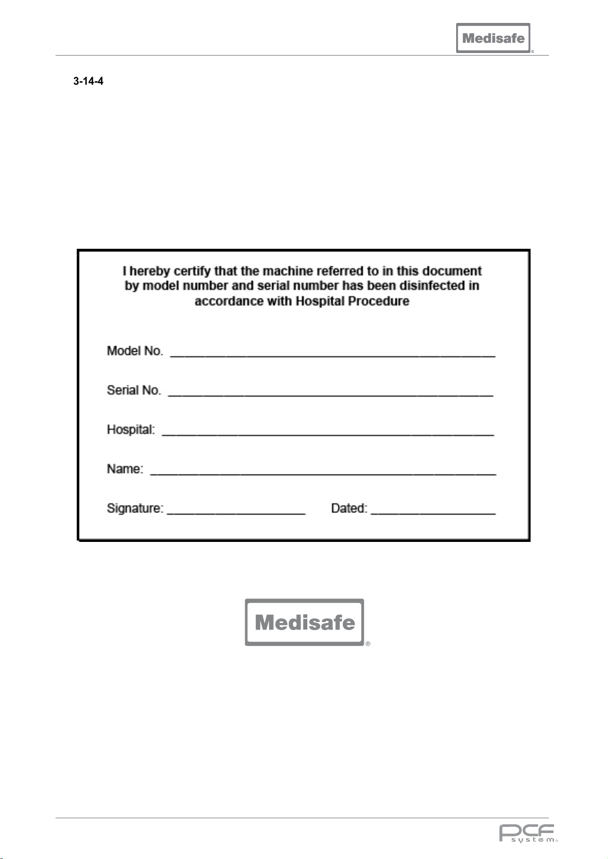
PCF Pro User Manual
Decontamination Certificate
Ensure that all items returned to your supplier are disinfected in accordance with the appropriate
hospital procedure for equipment of this type.
When returning this product to your supplier, the form must be completed and attached to the outside
of the crate/carton. If it is not visible, the courier and/or your supplier can refuse to handle this product.
DECONTAMINATION CERTIFICATE
Promoting a Clean and Safe Service
DOC01851 Page 53 of 74
Page 54
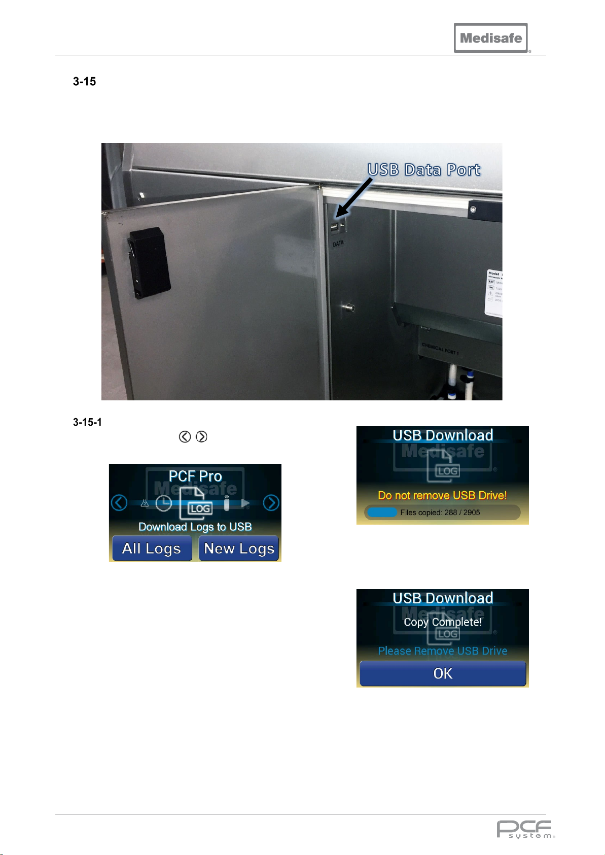
PCF Pro User Manual
Downloading the Cycle Log
The PCF Pro contains on board memory, which holds a record of every cycle run on the machine.
This Log can be downloaded to a USB flash drive via the USB Data port located in the chemical
cabinet on the right hand side of the machine.
Download Logs
1. Use the scroll arrows to cycle
through to the log icon.
2. Insert the USB flash drive into the USB
data port.
Note: the flash drive must be
formatted as FAT32.
3. Press All Logs to download all cycle
logs, or New Logs to download the
cycle logs since the last download.
4. Wait for the logs to be downloaded to
the USB drive. Do not remove the
USB Drive while downloading, as this
could corrupt its contents.
5. Once the log files have been
downloaded remove the USB drive
and press OK.
6. A file for each cycle will be stored in
the USB drive directory:
MEDISAFE\<machine serial number>\<cycle
range>\<cycle number>.txt
DOC01851 Page 54 of 74
Page 55
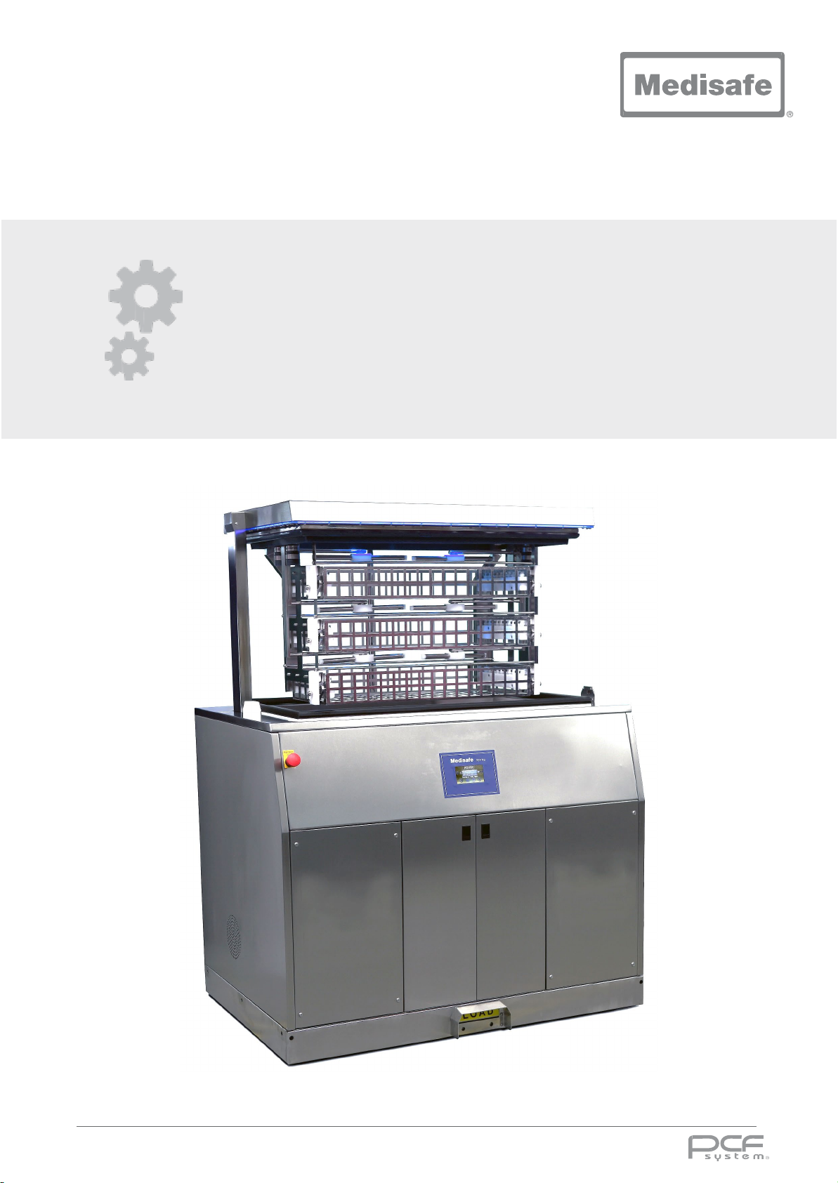
User Manual
4. Troubleshooting
4. Troubleshooting
DOC01851 Page 55 of 74
Page 56
PCF Pro User Manual
This section of the manual describes the types of PCF Pro problems which may occur, and indicates
probable causes/corrections.
If the situation cannot be corrected following the Troubleshooting Solutions, repeating the cycle, or if a
problem occurs which is not described, then please contact Medisafe. Service charges may be
incurred, consult your warranty for details. A trained service technician will promptly place your PCF
Pro in proper working order.
NOTE: Never permit unqualified persons to service the system. If a system problem cannot be
corrected using this section, please contact Medisafe.
Calling for Service: First, try to define the situation and determine whether it can be solved (see
section 4-1 and 4-2). If the situation cannot be solved, call Medisafe and provide the following
information:
• A description of the fault
• Model number
• Serial number
• A copy of the printout showing the error
Error Messages
Error
Code
1
2
3
4
5
6
7
10
Error Message Possible Causes and Solutions
Mains Power Removed Check mains supply to unit was not interrupted during a cycle
Chamber Overflow
Drain Timeout
Chamber Temperature
Sensor Mismatch
Chamber Fill Timeout
Chamber Opened Check lid is closed
Temperature Set Point Not
Maintained
Chamber Water Level Low
Switch the machine off then on again, if the problem persists turn the
machine and the water supply off and call a service engineer
Check tank filter clear, ensure drain is not blocked
Check that genuine Medisafe chemical is being used (EDA+ or 3E-
Zyme®)
Repeat cycle
Check water supply(s) to the machine are switched on
Check water inlet hose(s) for kinks
Repeat cycle, if the problem persists call a service engineer
Check that a non-foaming detergent is being used
Check for leaks
11
13
DOC01851 Page 56 of 74
Chamber Water Heat Rate
Low
Chemical Dosing
Repeat cycle
Temperature sensor or water heater element failure, please call a
service engineer.
Check chemical bottle level(s) and replace if required. Check chemical
pickup tube is inserted into the chemical container
Page 57
PCF Pro User Manual
Check the Cold water temperature is not above 35°C
Leave more time between washes for the machine to cool down.
16 17
Check tank filter is clear/clean
Check for leaks
Check baskets are docked properly
Check for leaks
39 40
47
Check water supply flow rate is sufficient
Repeat cycle
Sonic Cleaning Water Level
Low
Check tank filter is clear/clean
Check for leaks
Error
Code
14
15
18 19
51
20
21
22
23
38
Error Message Possible Causes and Solutions
Chamber Start Temperature
too High
Chamber Temperature Out of
Range
Level Sensor Invalid Repeat cycle
User Aborted Cycle Repeat cycle
Low Main Pump Pressure
High Main Pump Pressure
Temperature Set Point
Exceeded
Compressed Air Absent or
Pressure Low
The chamber has not cooled sufficiently since the last wash.
Switch the machine off then on again
Check baskets are docked properly
Check basket ports are not blocked
Check basket docking seals clean
Check basket ports are not blocked
Check basket docking seals clean
Repeat cycle
Check compressed air to the machine is turned on
41 43
45 46
42
44
48
49 57
58
50
52
53
54
56
Sonic Generator Fault Switch the machine off then on again
Maximum Cycle Time Expired
Emergency Stop Pressed
Microcontroller Error Switch the machine off then on again
Internal Ambient Temperature
too High
Real Time Clock Read Error Switch the machine off then on again
24V Power Supply Voltage
Out of Range
Overfill occurred during cool
down process
Low Wash Irrigation Pressure
Check tank filter clear, ensure drain is not blocked
Check for visual leaks
Determine reason why emergency stop was pressed before pulling the
button to release
Switch the machine off then check for blockages in the ventilation
holes
Switch the machine on again after an hour
Switch the machine off then on again
Check tank filter clear, ensure drain is not blocked
Repeat cycle
Check baskets are docked properly
Check basket ports are not blocked
Check basket docking seals clean
59
Unable to Store Cycle Log Repeat cycle
DOC01851 Page 57 of 74
Page 58
PCF Pro User Manual
Other Faults
Problem Possible Causes and solutions
• Insufficient detergent injected. Contact Medisafe
• Check that an approved chemical is being used
Poor Load Cleaning
Water Leaking from Lid
Area
Excessive Fill Time
Low Irrigation Port Flow
Rate
No Power to Unit or
Display is off
• Instrument basket is overloaded. Adjust load
• Instruments are excessively soiled
• Instruments have been left soiled for more than two hours
• Verify facility power meets Unit specifications
• Check instruments are lying flat in the basket and not pointing
up at the lid
• Check lid seal is undamaged
• Check incoming water pressure is above 2 bar (29 psi)
• Check water inlet valve is not blocked (beware of hot water
temperature!)
• Check all connectors are fully inserted
• Clean tank filter
• Check basket manifold ports are not blocked
• Check tank docked ports are not blocked
• Verify facility power meets Unit specifications
• Installation Main disconnect switch is in the OFF position
Turn main disconnect switch to the ON position
• Facility power is incorrect for unit. Correct facility power to
meet unit requirements
Access to the load in the
event of a power failure or
stuck lid mechanism
• Internal Circuit breaker has tripped, contact Medisafe
• The PCF Pro contains a manual override to allow the lid to be
opened, this must be carried out by trained service personnel.
Please contact Medisafe.
DOC01851 Page 58 of 74
Page 59
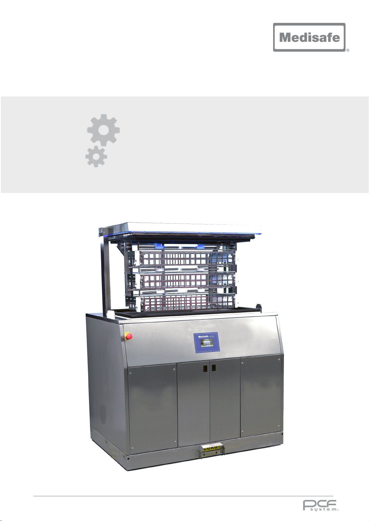
User Manual
5. Technical
5. Technical
DOC01851 Page 59 of 74
Page 60
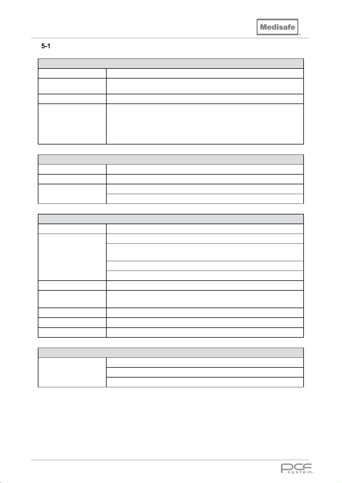
PCF Pro User Manual
General Specifications
General
Description Medical Device Class IIb
Intended Purpose
Operating Process Ultrasonic activity, Spray Arms and Irrigation Ports
Classifications
Internal and external cleaning of surgical instruments, hollow-ware, and
associated products
Class 1 electric shock protection, externally powered
No applied parts
IP rating – IPX0 (refer to BS EN 60601-1, para 6.3)
Not suitable for use in an oxygen rich environment
Mode of operation – intended for continuous use
User Interface
Display TFT Touch Screen
Foot Switch Used for hands free operation of carrier lifting system and cycle start and unload
Lighting
Lid Edge Multi Colour LEDs for visual indication of machine status
Blue LED Loading Illumination
Baskets
Quantity 3 baskets per machine
Two 10-way manifolds per standard basket, one on each end
With ten ports open each manifold outputs produces up to:
Features
3 bar (43.5psi) pressure with a flow rate of 50ml/s
2 Spray arms per basket
Soft-shot – Compressed air irrigation and spray arm water
Robot Instrument Capacity Up to 10 per basket (Total of up to 30)
Din Basket Compatibility
Tray Compatibility Size Length 657mm (25.9in) Width 343mm (13.5in) Height 79mm (3.1in)
Interior Dimensions Length 670mm (26.3in) Width 347mm (13.6in) Height 95mm (3.7in)
Max Load Weight 10kg / 22lb per basket (total 30kg / 66lb)
Full DIN Tray Standard to hold instruments (M20044) –
Length 484mm (19in) Width 253mm (10in) Height 76mm (3in)
Carrier Lift
Electrically actuated carrier lift
Features
Guided slide lock system, with retaining flag
Safety Edge strip and light beam for obstruction detection
DOC01851 Page 60 of 74
Page 61
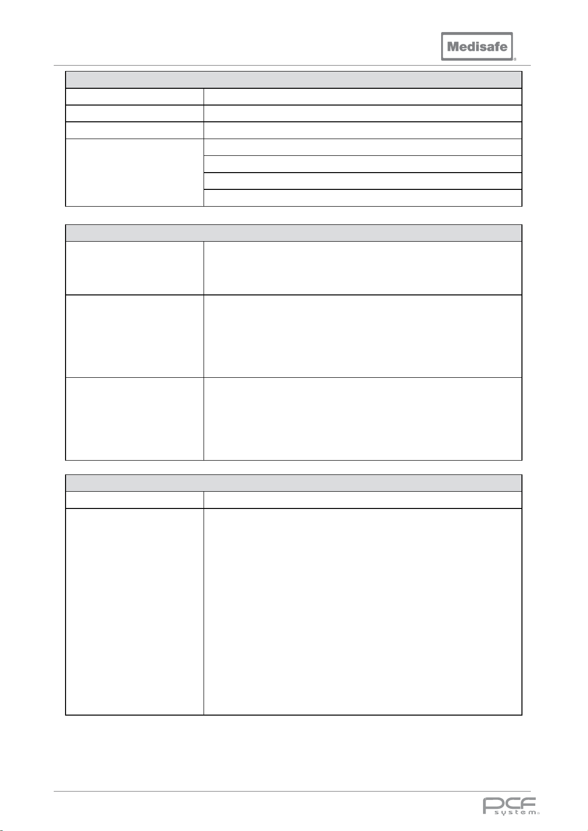
PCF Pro User Manual
Ultrasonics
Typical Frequency 38 to 40 kHz dependant on load
Transducers 84 piezo ceramic
Power 3kW
Pulsed Degas
Features
Electrical Supply
General
MED11180
(380 - 415VAC 50Hz)
MED11180
(200 - 230VAC 60Hz)
Water Supply
Auto-tune
Frequency Sweep
Reflectasonic Technology
Mains supply voltage fluctuations up to ±10% of the nominal voltage;
Transient over voltages typically present on the mains supply (Overvoltage
Category II).
Pollution Degree 2
Voltage: 380 - 415VAC 3P+N+PE (Three Phase + Neutral + Protective Earth)
Frequency: 50Hz
Power: 22kW
Site Current Capacity: ≥ 30A per phase
Site MCB and Disconnect Switch Current Rating: 40A
Site Wiring Cross-sectional area: 6 mm
Voltage: 200 - 230VAC 3P+PE (Three Phase + Protective Earth)
Frequency: 60Hz
Power: 18kW
Site Current Capacity: ≥ 48A per phase
Site MCB and Disconnect Switch Current Ratting: 63A
Site Wiring Cross-sectional area: 10mm
2
2
Back Siphonage Protection Integral AB type air gap and weir observing BS EN 1717
Per cycle stage:
• Pre-wash 40lts (10.5US gal)
• Wash 250lts (66US gal)
• Rinse 40lts (10.5US gal)
• Disinfection 40lts (10.5US gal)
• Disinfection Condensate 165lts (43.5US gal)
Consumption
(approximate)
• Cooling 105lts (28US gal)
Total Per supply:
• Cold 288lts (76US gal)
• Hot 247lts (65US gal)
• RO 145lts (38US gal)
Total Cycle 680ltrs (180US gal)
Consumption will vary depending on the cycle selected and the site facilities
DOC01851 Page 61 of 74
Page 62
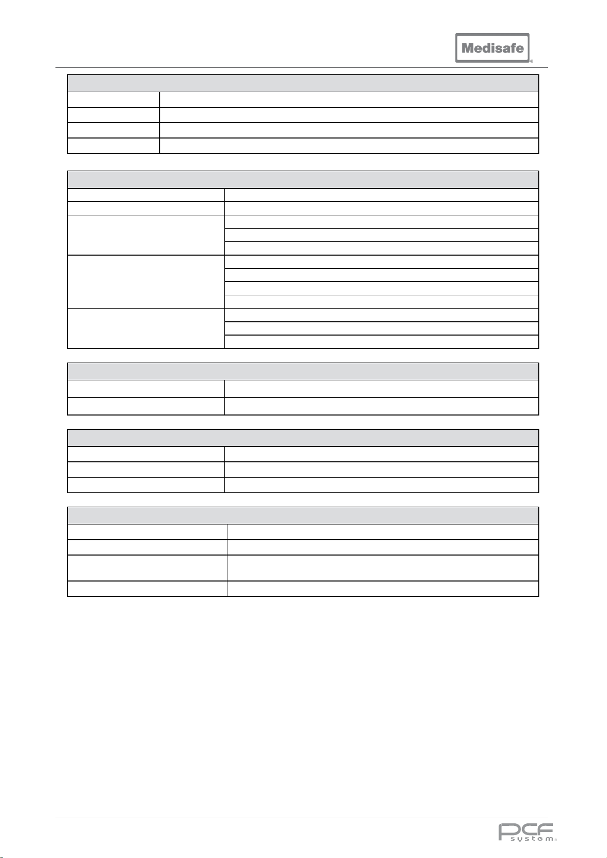
PCF Pro User Manual
Wash Chamber Liquid Volume
165 Litres (43.5US gal)
Wash Chamber Capacity
223 Litres (59US gal)
Width 925mm (36.4in)
Depth 385mm (15.2in)
Height 530mm (20.9in)
Width 1260mm (49.6in)
Depth 855mm (33.7in)
Height Lid Closed 1106mm (43.5in)
Height Lid Open 1650mm (65in)
Width 1510mm (59.5in)
Depth 1150mm (45.3in)
Height 1500mm (59.1in)
Drainage System
Type Gravity
Drain Connection 54mm (2.125in) OD outlet
Overflow Internally connected within the machine to the drain pipe, downstream of the drain valve
Effluent Temp 95°C (203°F)
Dimensions
Wash Chamber Dimensions
Outer Cabinet Dimensions
Shipping Container Dimensions
Weight
Operational weight (Dry)
Shipping weight 515kg (1135lb)
410kg (905lb)
Chemicals
Storage Integral Chemical cupboard for 2 bottles
Size and Nature of Bottles EDA+ or 3EZyme Fluid: 10L (2.6US gal) plastic bottle
Quantity Used per Cycle EDA+:1000ml (34fl.oz US) or 3EZyme:1380ml (47fl.oz US)
Environmental conditions
Use Indoor, Altitude up to 2000m (6562ft)
Ambient Operating Temperature 5°C - 40°C (41°F - 104°F)
Humidity
Noise Max SPL 69dBA @ 1m from the front of the machine
Maximum relative humidity 80% for temperatures up to 31°C (87.8°F)
decreasing linearly to 50% relative humidity at 40°C (104°F)
DOC01851 Page 62 of 74
Page 63
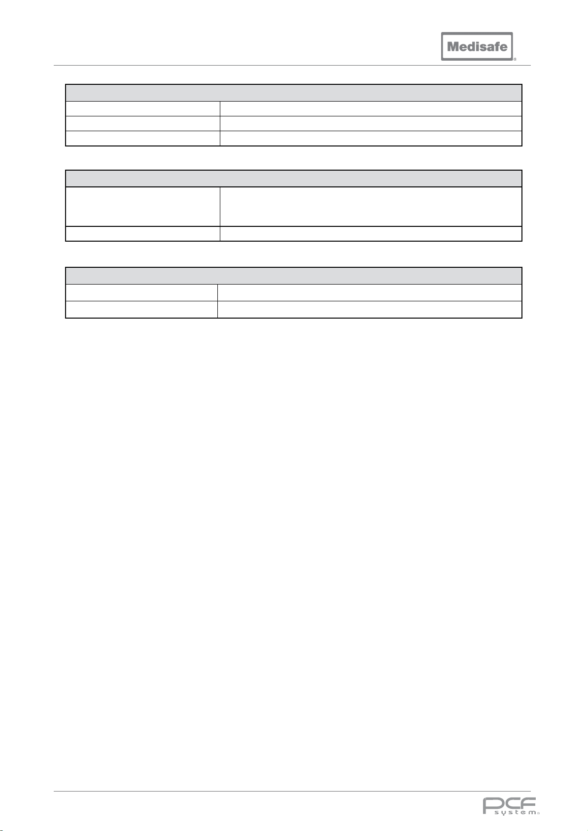
PCF Pro User Manual
Real Time Clock Battery
Type CR1220 (5012LC)
Typical Capacity 35 - 40 mAh
Standard Discharge Current 0.1 mA
Range and Accuracy
Measurement range 2Cº to 98Cº (36ºF to 208ºF)
Water Temperature
Time Displayed in minutes and seconds, accuracy ±0.5sec
Internal Data Storage
Type Micro SD FLASH Card
Typical Capacity 4GB (1 Million cycles)
Displayed and printed to the nearest ºC or ºF accuracy ±0.5ºC or ±0.9ºF
Max water temperature: 95ºC (limited by software and thermal trip)
DOC01851 Page 63 of 74
Page 64
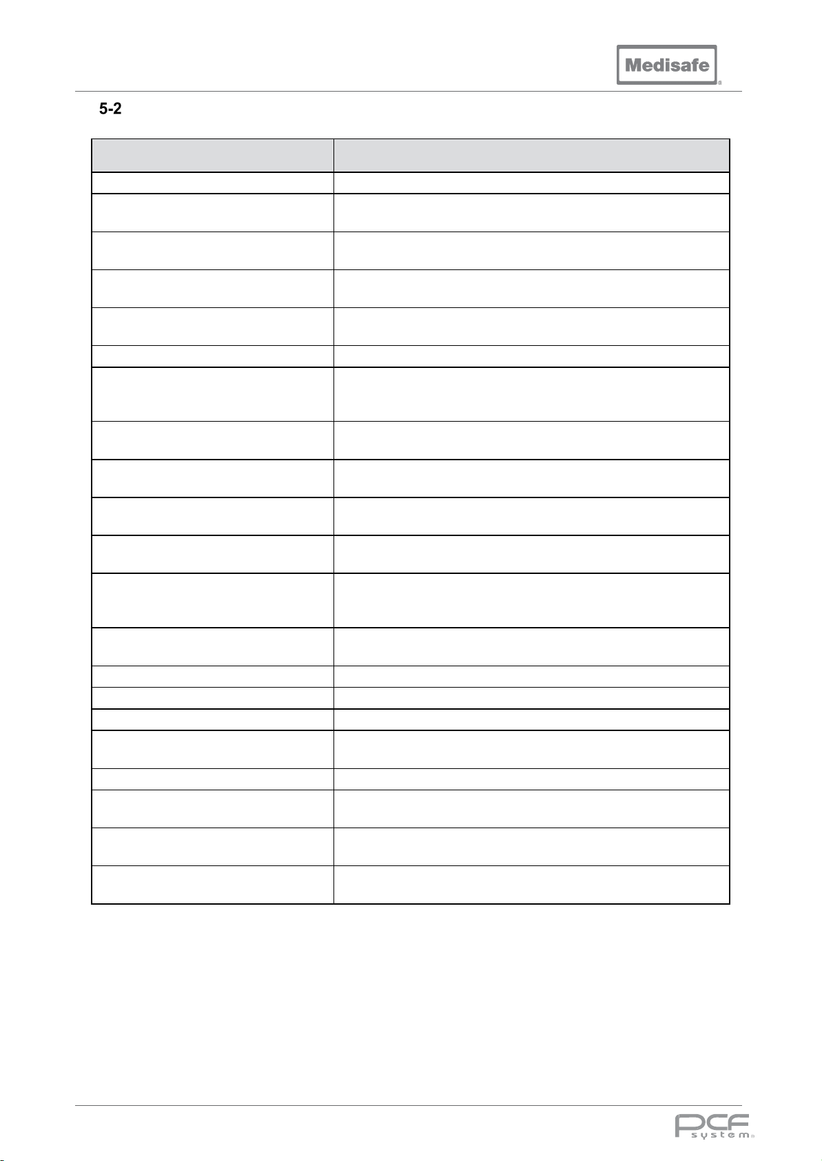
PCF Pro User Manual
1: General principles for design
requirements
MDD 93/42/EEC
Medical Device Directive
treat medical materials
and essential performance
devices
PD IEC/TR 60878:2015
Graphical symbols for electrical equipment in medical practice
PD 5304:2014
Guidance on the safe use of machinery
workers to the risks arising from physical agents (noise)
Applied Standards
Standard Description
2006/42/EC Machinery Directive
ISO 13849-1:2006
Safety of machinery - Safety-related parts of control systems -- Part
ISO 13849-1:2012
BS EN 60204-1:2006+A1:2009
BS EN ISO 15883-1:2009 +A1:2014
BS EN ISO 15883-2:2009
BS EN 61010-1:2010
BS EN 61010-2-040:2015
BS EN 60601-1-6:2010+A1:2015
BS EN 60601-1:2006 +A12:2014
BS EN 60601-1-2:2007
BS EN 62366-1:2015
Safety of machinery - Safety-related parts of control systems -- Part
2: Validation
Safety of machinery. Electrical equipment of machines. General
Washer-disinfectors. General requirements, terms and definitions
and test
Washer-disinfectors - Requirements and tests for washer-disinfectors
employing thermal disinfection for surgical instruments, anaesthetic
equipment, bowls, dishes, receivers, utensils, glassware, etc.
Safety requirements for electrical equipment for measurement,
control, and laboratory use
Particular requirements for sterilizers and washer-disinfectors used to
Medical electrical equipment. General requirements for basic safety
and essential performance
Medical electrical equipment. General requirements for basic safety
Medical electrical equipment. General requirements for basic safety
and essential performance. Collateral Standard. Electromagnetic
disturbances. Requirements and tests
Medical devices. Application of usability engineering to medical
BS EN ISO 13485:2012 Medical devices - Quality management systems
BS EN ISO 14971:2012 Medical devices - Application of risk management to medical devices
BS EN 1717:2000
EN 61326: 2013
2003/10/EC
2009/104/EC
Protection against pollution of potable water in water installations and
general requirements of devices to prevent pollution by backflow
Electrical equipment for measurement, control and laboratory use.
EMC requirements. General requirements
Minimum health and safety requirements regarding the exposure of
Minimum safety and health requirements for the use of work
equipment by workers at work
DOC01851 Page 64 of 74
Page 65
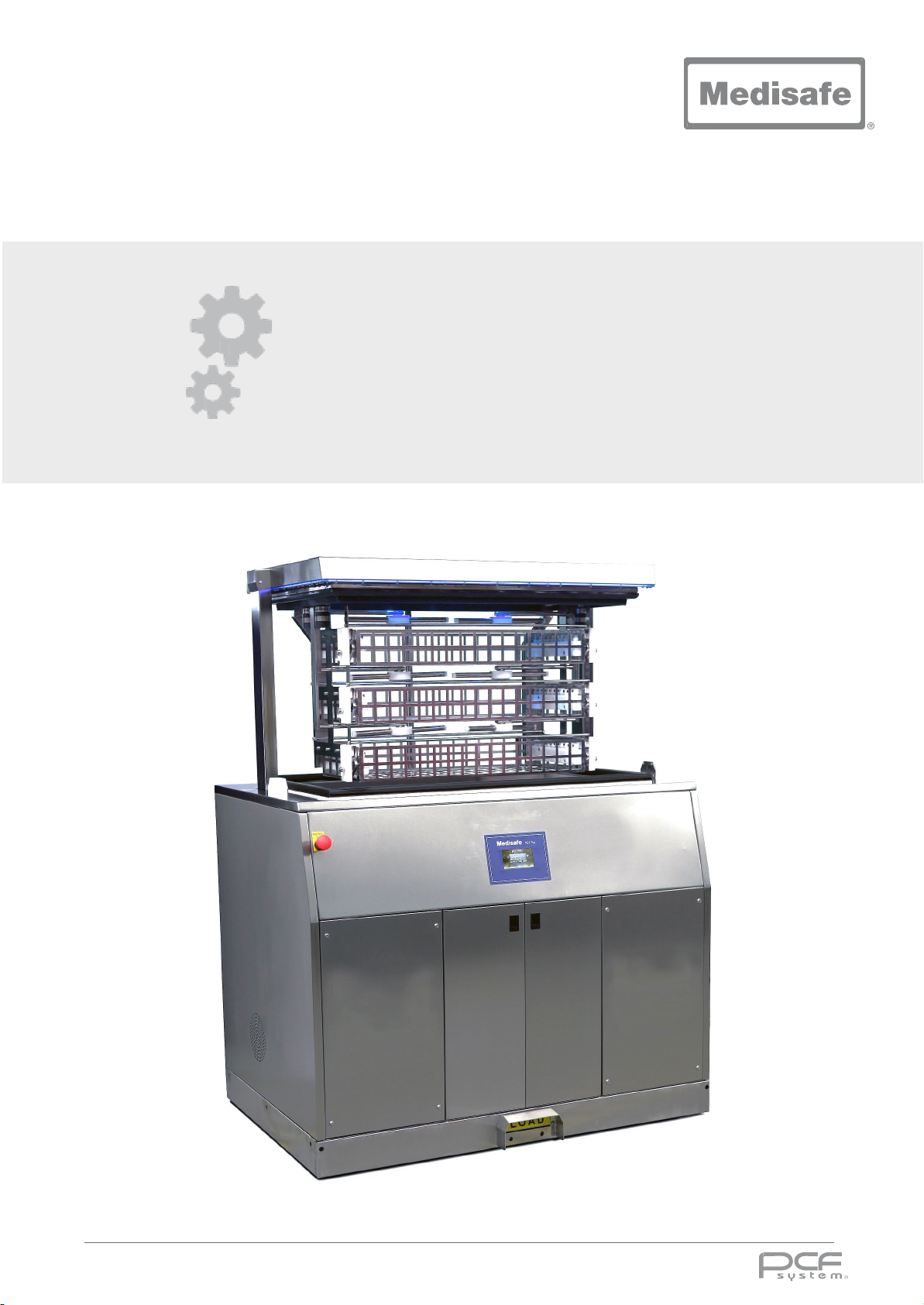
User Manual
6. Appendices
6. Appendices
DOC01851 Page 65 of 74
Page 66

PCF Pro User Manual
EMC
EMC & Electromagnetic Compatibility Data
Instructions/Notes regarding the PCF Pro and Electromagnetic compatibility (EMC) testing to
EN60601-1-2:2007
The PCF Pro has been tested regarding its ability to operate in an environment containing other
electrical/electronic equipment (including other medical devices).
The purpose of this testing is to ensure that the PCF Pro is not likely to adversely affect the normal
operation of other such equipment and that other such equipment is not likely to adversely affect the
normal operation of the PCF Pro.
Despite the testing of the PCF Pro that has been undertaken, normal operation can be affected by
other electrical or electronic equipment. Portable and mobile RF communications equipment can
affect medical electrical equipment.
As the PCF Pro is medical equipment, special precautions are required regarding EMC.
It is important that the PCF Pro is configured and installed/put into service, in accordance with the
instructions/guidance provided herein and is used only in the configuration as supplied.
The PCF Pro may be supplied with the following accessories: serial data cable (MED1017) and
thermal printer (MED1014.1)
The PCF Pro’s data cable must be restricted to less than 3m in length and should not be extended by
the user. If the PCF Pro is used with adapted cables or cables other than those supplied, this may
result in increased emissions or decreased immunity of the PCF Pro, in relation to EMC performance.
If the PCF Pro’s is used with a printer other than the one supplied this this may result in increased
emissions or decreased immunity of the PCF Pro, in relation to EMC performance.
It should be noted that the cables provided with the PCF Pro should not be used on other equipment.
To do so may result in increased emissions or decreased immunity of the other equipment in relation
to EMC performance.
The PCF Pro should not be used adjacent to or stacked with other equipment. If adjacent or stacked
use with other equipment is necessary, the PCF Pro and the other equipment should be observed /
monitored to verify normal operation in the configuration in which it will be used.
For the purposes of EN60601-1-2, the PCF Pro has an essential performance as follows:
Functions within the operating cycle should continue to operate as normal, and the product should
complete its operating cycle correctly.
DOC01851 Page 66 of 74
Page 67
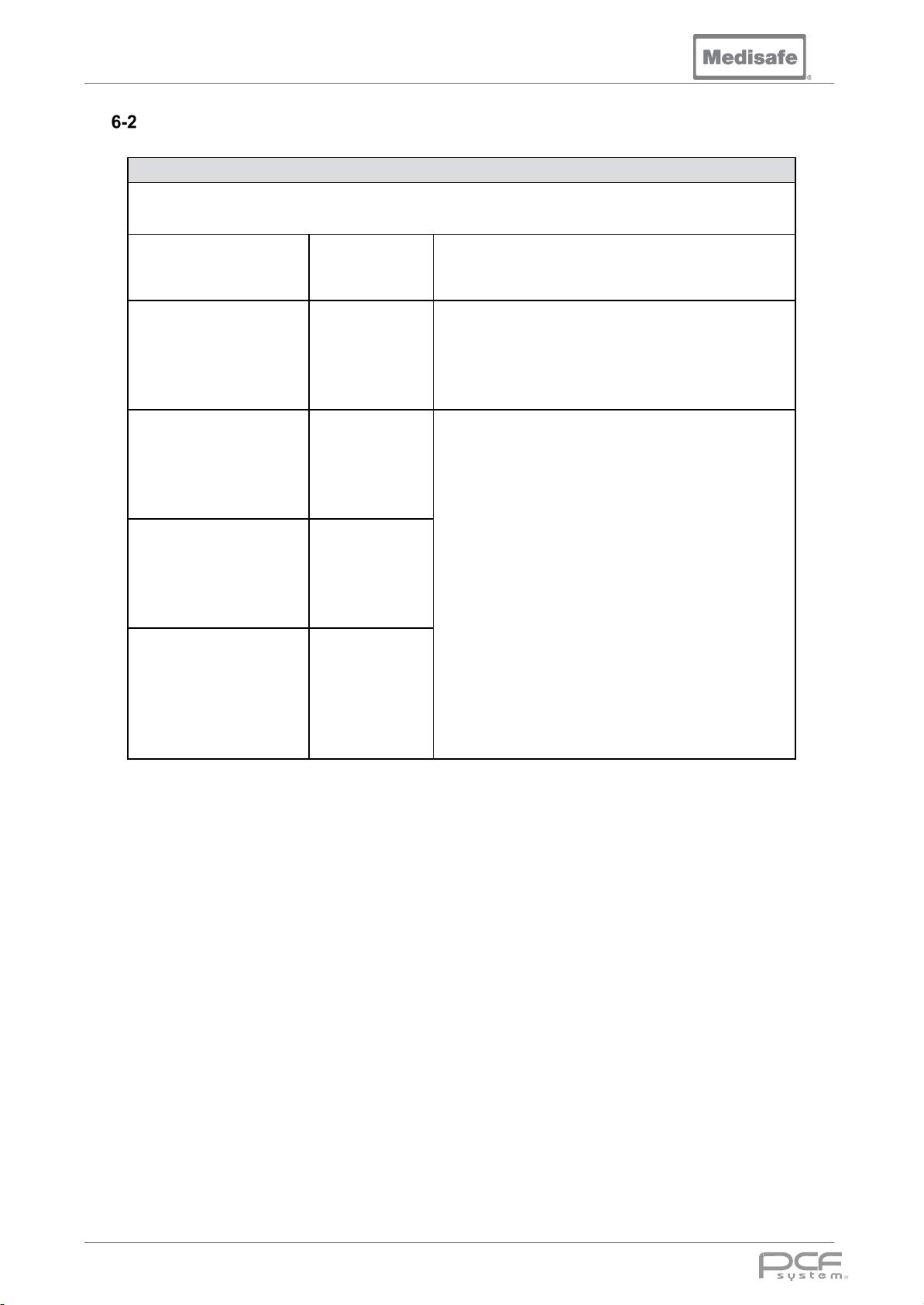
PCF Pro User Manual
Guidance and Manufacturer’s Declaration – Electromagnetic Emissions
Electromagnetic Emissions
The PCF Pro is intended for use in the electromagnetic environment specified below. The
customer or the user of the PCF Pro should assure that it is used in such an environment.
Emissions test Compliance Electromagnetic environment - guidance
RF emissions
CISPR 11
Group 1
The PCF Pro uses RF energy only for its internal
function. Therefore, its RF emissions are very low
and are not likely to cause any interference in
nearby electronic equipment.
RF emissions
CISPR 11
Harmonic emissions
IEC 61000-3-2
Voltage fluctuations /
flicker emissions
IEC 61000-3-3
Class A
Not Applicable
Not Applicable
The PCF Pro is suitable for use in all
establishments other than domestic and those
directly connected to the public low-voltage power
supply network that supplies buildings used for
domestic purposes.
DOC01851 Page 67 of 74
Page 68
PCF Pro User Manual
Guidance and Manufacturer’s Declaration – Electromagnetic Immunity
Electromagnetic Immunity
The PCF Pro is intended for use in the electromagnetic environment specified below. The customer or
the user of the PCF Pro should assure that it is used in such an environment.
Immunity test IEC 60601 test level Compliance level
Electrostatic discharge
(ESD)
IEC 61000-4-2
Electrical fast transient /
burst
IEC 61000-4-4
Surge
IEC 61000-4-5
Voltage dips, short
interruptions and voltage
variations on power supply
input lines
IEC 61000-4-11
± 6 kV contact
± 8 kV air
± 2 kV for power supply
lines
± 1 kV for input / output
lines
± 1 kV line(s) to line(s)
± 2 kV line(s) to earth
<5% U
T
(>95 % dip in U
0.5 cycle
40% U
(60 % dip in U
for 5 cycles
70 % U
(30 % dip in U
for 25 cycles
<5% U
(>95 % dip in U
) For
T
T
)
T
T
)
T
T
) For 5
T
s
± 6 kV contact
± 8 kV air
± 2 kV for power supply
lines
Input / output line tests
are not applicable.
± 1 kV differential
mode
± 2 kV common mode
Not Applicable
(Rated input current
>16A per phase)
Not Applicable
(Rated input current
>16A per phase)
Not Applicable
(Rated input current
>16A per phase)
<5% U
(>95 % dip in U
s
T
) For 5
T
Electromagnetic
environment - guidance
Floors should be wood,
concrete or ceramic tile. If floors
are covered with synthetic
material, the relative humidity
should be at least 30%.
Mains power quality should be
that of a typical commercial or
hospital environment.
Mains power quality should be
that of a typical commercial or
hospital environment.
Mains power quality should be
that of a typical commercial or
hospital environment. If the
user of the PCF Pro requires
continued operation during
power mains interruptions; it is
recommended that the PCF Pro
be powered from an
uninterruptable power supply or
a battery.
Power frequency
(50/60Hz) Magnetic field
IEC 61000-4-8
3 A/m 3 A/m (50Hz only)
Note: UT is the A.C. mains voltage prior to application of the test level.
DOC01851 Page 68 of 74
If incorrect operation occurs,
it may be necessary to
position the PCF Pro further
from sources of power
frequency magnetic fields or
to install magnetic shielding.
The power frequency
magnetic field should be
measured in the intended
installation location to
assure that it is sufficiently
low.
Page 69
PCF Pro User Manual
the user of the PCF Pro should assure that it is used in such an environment.
a. Field strengths from fixed transmitters, such as base stations for radio (cellular/cordless) telephones and land
b.
Guidance and Manufacturer’s Declaration – Electromagnetic Immunity
The PCF Pro is intended for use in the electromagnetic environment specified below. The customer or
Immunity test
Conducted RF
IEC 61000-4-6
Radiated RF
IEC 61000-4-3
IEC 60601 test
level
3 Vrms
150 kHz to 80 MHz
3 V/m
80 MHz to 2.5 GHz
Compliance
level
3 Vrms
150 kHz to 80
MHz
3 V/m
80 MHz to 2.5
GHz
Electromagnetic environment guidance
Portable and mobile RF communications
equipment should be used no closer to any
part of the PCF Pro, including cables, than
the recommended separation distance
calculated from the equation applicable to the
frequency of the transmitter.
Recommended separation distance (d)
d = 1.2√P
d = 1.2√P 80 MHz to 800 MHz
d = 2.3√P 800 MHz to 2.5 GHz
Where P is the maximum output power rating
of the transmitter in watts (W) according to the
transmitter manufacturer and d is the
recommended separation distance in metres
(m).
Fields strengths from fixed RF transmitters, as
determined by an electromagnetic site survey
(see Note a) should be less than the
compliance level in each frequency range (see
Note b)
Interference may occur in the vicinity of
equipment marked with the following symbol:
Note 1: At 80 MHz and 800 MHz, the higher frequency range applies.
Note 2: These guidelines may not apply in all situations. Electromagnetic propagation is affected by absorption and
reflection from structures, objects and people.
mobile radios, amateur radio, AM and FM radio broadcast and TV broadcast cannot be predicted theoretically with
accuracy. To assess the electromagnetic environment due to fixed RF transmitters, an electromagnetic site survey
should be considered. If the measured field strength in the location in which the PCF Pro is used exceeds the
applicable RF compliance level above, the PCF Pro should be observed to verify normal operation. If abnormal
performance is observed, additional measures may be necessary, such as re-orienting or relocating the PCF Pro.
Over the frequency range 150 kHz to 80 MHz, field strengths should be less than 3 V/m.
DOC01851 Page 69 of 74
Page 70
PCF Pro User Manual
is intended for use in an electromagnetic environment in which radiated RF
can help prevent
as recommended below,
Rated maximum output power
150 KHz to 80 MHz
d = 1.2√P
80 MHz to 800 MHz
d = 1.2√P
800 MHz to 2.5 GHz
d = 2.3√P
0.01
0.12
0.12
0.23
0.1
0.38
0.38
0.73 1 1.2
1.2
2.3
10
3.8
3.8
7.3
12 23
Separation Distances Between PCF Pro and Mobile RF Equipment
Recommended separation distances between
portable and mobile RF communications equipment and the PCF Pro
The PCF Pro
disturbances are controlled. The customer or the user of the PCF Pro
electromagnetic interference by maintaining a minimum distance between portable and mobile
RF communications equipment (transmitters) and the PCF Pro
according to the maximum output power of the communications equipment.
Separation distance according to frequency of transmitter
m
of transmitter
W
100
12
For transmitters rated at a maximum output power not listed above, the recommended
separation distance d in metres (m) can be estimated using the equation applicable to the
frequency of the transmitter, where P is the maximum output power rating of the transmitter in
watts (W) according to the transmitter manufacturer.
Note 1: At 80 MHz and 800 MHz, the separation distance for the higher frequency range
applies.
Note 2: These guidelines may not apply in all situations. Electromagnetic propagation is
affected by absorption and reflection from structures objects and people.
DOC01851 Page 70 of 74
Page 71
PCF Pro User Manual
Warranty
To ensure continued efficiency and long operational life,
your new PCF Pro is covered by a one-year
warranty/5,000 cycle warranty which is arranged and
administered by Medisafe (UK) Ltd. Details of the warranty
are explained in this section.
Subject to the following terms and conditions, Medisafe
(UK) Ltd. warrants that any item of THE BASIC
WARRANTY ITEMS of the unit (hereinafter called “new
PCF Pro”) manufactured by Medisafe (UK) Ltd. shall be
free from any defects in material and workmanship under
normal use and maintenance.
Any item of THE BASIC WARRANTY ITEMS covered by
the limited warranty will be repaired or replaced free of
charge by Medisafe (UK) Ltd. or any distributor authorised
by Medisafe (UK) Ltd. to act as their agent (hereinafter
called “authorised Medisafe dealer or distributor”).
The Basic Warranty Items
THE BASIC WARRANTY ITEMS are any items (except
THE SPECIFIC EXCLUDED ITEMS) of this new PCF Pro
which are warranted by an authorised Medisafe dealer or
distributor within 12 months or 5,000 cycles (whichever
occurs first) of the WARRANTY START DATE when this
new PCF Pro is first installed by, or for you (the original
purchaser) as set forth on the Memorandum of
Registration.
THE BASIC WARRANTY ITEMS listed below are
warranted within 12 months or 5,000 cycles (whichever
occurs first) from the WARRANTY START DATE against
defects in manufacture.
• Solenoid valves
• Electric motors and pumps
• Switches
• Electronic control circuits
• Water heating elements
• Ultrasonic transducers
The Specific Excluded Items
THE SPECIFIC EXCLUDED ITEMS are any items of this
new PCF Pro which are not included in THE BASIC
WARRANTY ITEMS and are therefore not subject to the
terms and conditions of the PRODUCT WARRANTY.
Expendable items, which will deteriorate and require
replacement with normal use of the Washer (for example:
lid seal, CPE ports, O-rings, various types of gaskets and
hoses, LEDs (if fitted), and other expendable parts not
specifically listed).
Fair wear and tear of any part, normal maintenance
service items, and the parts and any material used in
connection with the new PCF Pro.
Normal deterioration or damage to plated parts, paint coat,
and rubber parts, caused by daily wear and tear and
exposure to atmosphere and environment.
Minor irregularities not affecting quality, performance or
function of the new PCF Pro parts thereof (e.g. slight noise
or vibration) or which appear only under particular
abnormal conditions.
Damage caused by insufficient or improper maintenance
(e.g. negligence of the daily, weekly, and monthly periodic
inspections and any servicing requirements as described
and specified within this manual).
Damage caused by using a part or lubricants not approved
by an authorised Medisafe dealer or distributor or being
repaired or replaced by a person who is not an authorised
Medisafe dealer or distributor.
Damage caused by accident, abuse, or negligence of the
proper handling as set out in this Owner’s Manual, misuse
of the new PCF Pro, use of the new PCF Pro under
unusual conditions, and modifications of or to the new
PCF Pro or any component/parts thereof not
recommended or approved by an authorised Medisafe
dealer or distributor.
Damage caused by external influences such as chemical
spillage, accident, fire, and disasters due to human fault,
negligence or Act of God.
Damage to the external casing, wash chamber, load
baskets, or any part of the new PCF Pro which may come
into contact with the load carrier during the process of
loading/ unloading the new PCF Pro.
All charges incidental to breakdowns, such as loss of use
of the new PCF Pro, loss of time, inconvenience,
telephone, transportation, loss or damage to personal
property or loss of revenues, or other matter not
specifically included.
Damage caused by incorrect installation of the new PCF
Pro, which could cause operational failure or impairment
either immediately after such installation or at any time
within the period of this PRODUCT WARRANTY.
Medisafe (UK) Ltd. reserves the right of final decision on
all manufacturers’ warranty claims.
Nothing herein affects the statutory rights of the
consumer.
DOC01851 Page 71 of 74
Page 72
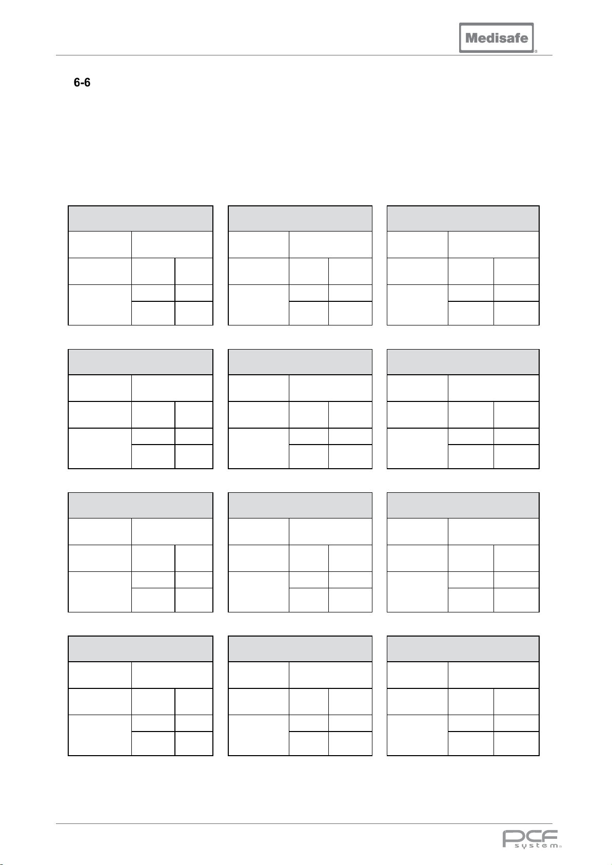
PCF Pro User Manual
Serviced by/
Serviced by/
Serviced by/
Cycles since
Cycles since
Cycles since
Next service
Cycles
Date
Next service
Cycles
Date
Next service
Cycles
Date
Serviced by/
Serviced by/
Serviced by/
Cycles since
Cycles since
Cycles since
Next service
Cycles
Date
Next service
Cycles
Date
Next service
Cycles
Date
Serviced by/
Serviced by/
Serviced by/
Cycles since
Cycles since
Cycles since
Next service
Cycles
Date
Next service
Cycles
Date
Next service
Cycles
Date
Serviced by/
Serviced by/
Serviced by/
Cycles since
Cycles since
Cycles since
Next service
Cycles
Date
Next service
Cycles
Date
Next service
Cycles
Date
Service Record
Medisafe recommend that your PCF Pro be serviced every 3 months in accordance with the schedule
contained within the PCF Pro Service Manual, which also contains the technical description of the
machine. This record must be completed by the engineer conducting the service and should be made
available in the event of a warranty claim or breakdown repair.
Note: No user serviceable parts inside. Service and repair should be referred to trained and qualified
persons only - the product supplier (or Medisafe UK Ltd) to avoid personal injury, improper equipment
performance, invalidation of the equipment warranty or other costly damage.
3 Month
6 Month
9 Month
Date
last service
due
Date
last service
due
Date
Date
last service
due
Date
last service
due
12 Month
Date
last service
due
15 Month
18 Month
Date
last service
due
21 Month
Date
24 Month
27 Month
Date
last service
due
last service
due
Date
last service
due
30 Month
Date
last service
due
33 Month
DOC01851 Page 72 of 74
last service
due
36 Month
Date
last service
due
Page 73
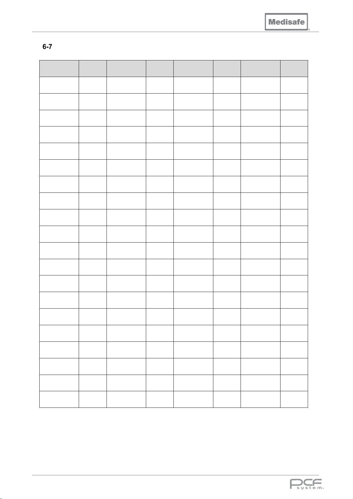
PCF Pro User Manual
Operator PIN Number Codes
Operator # Pin Operator # Pin Operator # Pin Operator # Pin
1 2040 21 4060 41 6080 61 8020
2 2181 22 4121 42 6141 62 8161
3 2262 23 4282 43 6222 63 8242
4 2363 24 4383 44 6323 64 8343
5 2484 25 4424 45 6444 65 8464
6 2545 26 4565 46 6585 66 8525
7 2626 27 4646 47 6666 67 8686
8 2727 28 4747 48 6776 68 8787
9 2848 29 4868 49 6888 69 8828
10 2989 30 4929 50 6949 70 8969
11 3070 31 5090 51 7030 71 9050
12 3171 32 5191 52 7131 72 9151
13 3292 33 5232 53 7252 73 9272
14 3353 34 5373 54 7393 74 9333
15 3434 35 5454 55 7474 75 9494
16 3535 36 5555 56 7575 76 9995
17 3656 37 5676 57 7696 77 9636
18 3797 38 5737 58 7757 78 9777
19 3878 39 5898 59 7838 79 9858
20 3979 40 5999 60 7939 80 9959
DOC01851 Page 73 of 74
Page 74
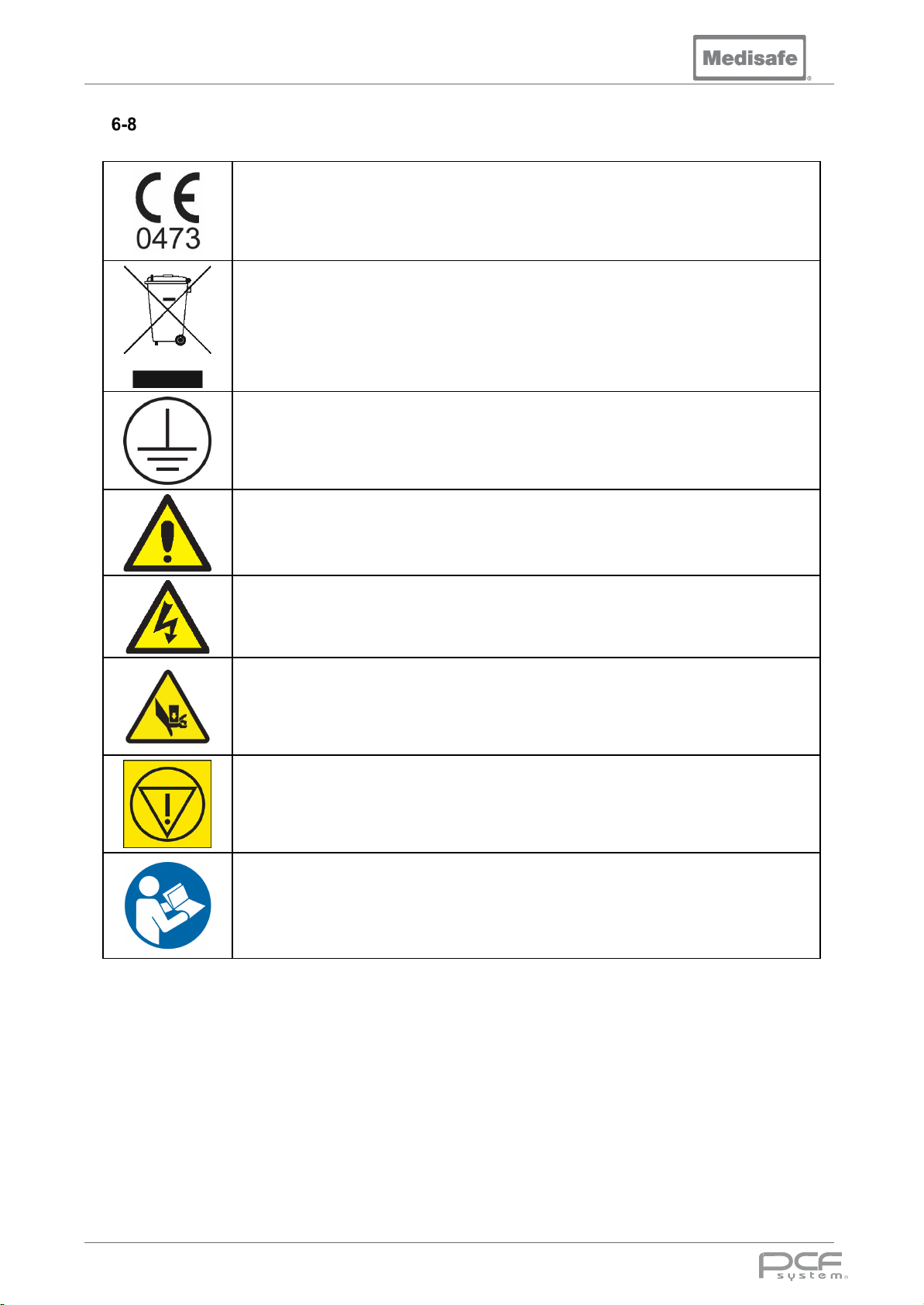
PCF Pro User Manual
Symbols Glossary
Conformité Européenne: A conformity marking for certain products sold within the
European Economic Area (EEA) since 1985. The CE marking is also found on
products sold outside the EEA that are manufactured in, or designed to be sold in,
the EEA. The 4-digit number below the CE mark is the identification number of the
notified body involved in the conformity assessment procedure.
WEEE directive: Shows that a product can be recycled separately from other
household waste under the WEEE directive
Protective Earth symbol
Standard Hazard Label (used for Warnings and Hazards)
Standard Electrical Danger Label
Standard Crush Hazard Label
Emergency Stop
atory Read - Read this manual before operating this machine
Mand
DOC01851 Page 74 of 74
 Loading...