

Page 1

NOTES ON THIS MANUAL
Keep these instructions with your computer at all times. The
proper set up, use and care can help extend the life of your
computer. In the event that you transfer ownership of this
computer, please provide these instructions to the new
owner.
This manual is divided into sections to help you locate the
information you require. Along with the Table of Contents at
the beginning of this manual, an Index has been provided to
help you find topical information.
If you want to start up your PC immediately, please read the
chapters Operational Safety (page 3) and Setting up and
Getting Started (page 11).
We strongly recommend you read this entire manual to ensure the proper set-up and operation of your PC.
Many application programs incorporate extensive help functions. As a general rule, you can access help functions by
pressing F1 on the keyboard. These help functions will be
available to you while you are using the Microsoft Windows
®
operating system or the respective application program.
We strongly recommend that you read the Online Manual for
your PC, which can be found in the Start Menu.
Information about your PC
This interactive manual is designed to provide additional information about your PC as well as useful links accessible via
the World Wide Web.
Windows
xp
invites you to a tour (notes on the task bar) to
familiarize yourself with the operating system. We listed further useful sources of information starting on page 64.
Page 2

ii
AUDIENCE
These instructions are intended for both the novice and advanced user. Regardless of the possible professional utilization, this PC is designed for day-to-day household use. The
functions and applications for use with this PC have been
designed with the entire family in mind.
PURCHASE DETAILS
Enter your purchase details below for quick reference.
Serial Number ......................................
Date of Purchase ......................................
Place of Purchase ......................................
You will find the PC serial number on the Service Hotline
card. The serial number also appears on the rear of the PC.
QUALITY
Medion has selected the components in this computer for their
high level of functionality, ease of use, safety and reliability.
Through balanced hardware and software design we are able to
provide you with an innovative personal computer useful for applications relating to both work and leisure.
We are pleased to welcome you as our newest customer.
Thank you for choosing our products.
© 2002 Medion®. All rights reserved. Microsoft®, MS-DOS®, and Windows are registered trademarks of Microsoft Corporation in the U.S. and other countries. Pentium
®
is a
registered trademark of Intel Corporation. The names of actual companies and products
mentioned herein may be the trademarks of their respective owners.
This product incorporates copyright protection technology that is protected by method
claims of certain U.S. patents and other intellectual property rights owned by Macrovision Corporation and other rights owners. Use of this copyright protection technology
must be authorized by Macrovision Corporation, and is intended for home and other
limited viewing uses only unless otherwise authorized by Macrovision Corporation.
Reverse engineering or disassembly is prohibited.
Information in this document is subject to change without notice.
Page 3

iii
Table of Contents
Notes on This Manual............................................................. i
Operational Safety................................................................ 3
Data Security ...................................................................... 4
Important Additional Safety Instructions.................................. 5
Included with Your PC ........................................................... 9
Setting UP ................................................................. 11
Positioning the Monitor........................................................ 11
Working in Comfort.......................................................... 12
Set-Up Location ................................................................. 13
Ambient Temperature....................................................... 13
Front connectors ................................................................ 14
Connecting ................................................................ 15
Cabling ............................................................................. 15
Connecting the Monitor..................................................... 16
Connecting a PS/2 Keyboard ............................................. 17
Connecting a USB Keyboard .............................................. 17
Connecting a PS/2 Mouse.................................................. 17
Connecting a USB Mouse .................................................. 17
Connecting Parallel Devices............................................... 18
Connecting Serial Devices ................................................. 18
Modem/ISDN Connection .................................................. 19
LAN Connection ............................................................... 20
Connecting Devices to the Gaming Port............................... 20
Connecting Speakers/Audio Output .................................... 20
Connecting a Sound Source/Audio Input ............................. 21
Connecting a Microphone .................................................. 21
Connecting the PC to a Television........................................ 21
Connecting a recording source / Video inlet ......................... 22
USB/IEEE 1394 ............................................................... 22
Connecting the Power Supply ............................................ 23
Getting Started ......................................................... 24
Short description of the Windows® Desktop ............................ 26
Operation .................................................................. 31
The Keyboard .................................................................... 31
Multimedia Functions........................................................ 38
Page 4

iv
Table of Contents (continued)
The Hard Drive .................................................................. 39
Important directories ....................................................... 40
The Card Reader ................................................................ 41
The Optical Drive ............................................................... 42
Loading a Disk: ............................................................... 42
How to remove a Disc: ..................................................... 43
The CD-Rom/DVD drive as Boot D drive.............................. 43
DVD Technology .............................................................. 43
Subjects Concerning the CD-Rewriter.................................... 46
Recordable/Rewriteable CDs (CD-R/CD-RW)........................ 46
What Types of CDs Can Be Copied?.................................... 47
What Does ... Mean?........................................................ 48
The Graphics Card.............................................................. 52
Performance characteristics............................................... 52
Current image playback frequencies ................................... 52
Connecting the PC to a Television ...................................... 53
System Requirements ...................................................... 54
The Radio-/TV- Tuner Card .................................................. 55
The Sound Card ................................................................. 55
Audio Configuration ......................................................... 56
The MIDI/Game Port ........................................................ 57
USB Port........................................................................... 57
IEEE 1394 (Fire Wire) ......................................................... 58
Application Options for IEEE1394 ....................................... 58
Technical Specifications .................................................... 58
The Network...................................................................... 59
What is a Network?.......................................................... 59
What Do You Need for Networking?.................................... 60
Troubleshooting within the Network.................................... 62
Modem / ISDN................................................................... 63
What is a Modem? ........................................................... 63
Software........................................................................... 64
Getting to Know Windows XP............................................. 64
Writing CDs .................................................................... 65
Installation of Software .................................................... 66
Windows Activation.......................................................... 69
BIOS Setup .................................................................... 70
Page 5

v
Table of Contents (continued)
Self-Help ................................................................... 73
Data and System Security ................................................... 73
Data Security .................................................................. 73
Maintenance Programs ..................................................... 73
Password Reset File ......................................................... 73
System Recovery ............................................................... 74
Correction ...................................................................... 74
Restoring the Factory Settings ............................................. 75
Limits of the Recovery ...................................................... 75
Carrying out a Restore ..................................................... 75
FAQ – Questions frequently asked ........................................ 76
Customer Service ...................................................... 79
Troubleshooting ................................................................. 79
Localize the Cause ........................................................... 79
Errors And Possible Causes ............................................... 80
Driver Support................................................................... 81
Additional Support.............................................................. 81
Cleaning and Care .............................................................. 82
Recycling and Disposal........................................................ 82
Transporting the PC ......................................................... 83
Upgrades and Repairs ......................................................... 83
Notes for Service Engineers............................................... 83
Standards ......................................................................... 87
Electromagnetic Compatibility............................................ 87
Electrical Safety............................................................... 88
Ergonomics..................................................................... 88
Noise Emission ................................................................ 88
Supplementary Information............................................... 88
FCC Compliance Statement ............................................... 89
Declaration of Conformity ................................................. 90
Warranty .......................................................................... 91
Limitation of Warranty...................................................... 91
Limits of Liability ............................................................. 91
Local Law ....................................................................... 92
Making Copies of This Manual............................................... 92
Index................................................................................ 93
Page 6

vi
Page 7

1
CChhaapptteerr 11
Safety and Maintenance
Subject Page
Operational Safety …………………………………… 3
Data Security ……………………………………………… 4
Important Additional Safety Instructions … 5
Page 8

S
S
AAFFEETTYY AANNDD
M
M
AAIINNTTEENNAANNCCE
E
2
Page 9
O
O
PPEERRAATTIIOONNAALL
S
S
AAFFEETTY
Y
3
OPERATIONAL SAFETY
Please read this chapter carefully and observe all listed notes.
This ensures a reliable operation and long life expectancy of
your PC.
• DO NOT allow children to play unattended
with electrical equipment.
• DO NOT open the PC casing or use the PC
with the casing removed. When the casing is
open there is a danger to life from electric shock.
• DO NOT insert objects through the slots
and openings of the PC. This may lead to elec-
tric shock or an electrical short-circuit or fire that
will damage your PC.
• Connect the PC ONLY to an earthed, easy accessible
power socket. For disconnecting the PC from the
mains, unplug the power cord from the mains socket.
• DO NOT cover the slots and openings in
the PC casing. These openings are for ventila-
tion purposes. Covering these vents may lead
to overheating.
• This PC is NOT designed for use within in-
dustrial environments.
• CD-ROM-/CDRW-/DVD-drives are Laser Class
1 devices. These lasers must remain in their
sealed PC casing. DO NOT remove the drive
covers, as exposure to the lasers may
prove harmful.
• DO NOT look directly into the laser, even
when wearing eye protection.
Page 10
S
S
AAFFEETTYY AANNDD
M
M
AAIINNTTEENNAANNCCE
E
4
For U.S. / Canadian purposes:
Danger — Invisible laser radiation when open. Avoid direct exposure to beam.
Danger — radiations invisibles du laser en cas d’ouverture. Eviter
toute exposition directe au faisceau.
This product is certified by the manufacturer to comply with DHHS
rules 21CFR, Chapter 1, Subchapter J, applicable at date of manufacturer. Refer to optical drive labels for additional details.
Please contact Customer Service when:
• ... the power cord or the attached plug is worn or
damaged. Have the defective power cord replaced with
an original cable. Never try to repair a defective cable.
• ... the housing of the PC is damaged or liquids have
penetrated. Have the PC checked by Customer Service
first. Otherwise it is possible the PC cannot be operated
safely which might cause danger to life by electric shock!
The power cord is worn or damaged.
DATA SECURITY
Every time you update your data make back-up
copies on an external storage medium. The supplier does not assume liability for data loss or
damage to data storage units, and no claims can
be accepted for damages resulting from the loss
of data or consequential losses.
Page 11

I
I
MMPPOORRTTAANNTT
A
A
DDDDIITTIIOONNAALL
S
S
AAFFEETTYY
I
I
NNSSTTRRUUCCTTIIOONNS
S
5
IMPORTANT ADDITIONAL SAFETY INSTRUCTIONS
When using any electronic equipment, basic safety precautions should always be taken. Following the guidelines below
can reduce the risk of fire, electric shock and injury to person:
• Do not use this product near water (e.g., near a bathtub, wash bowl, kitchen sink or laundry tub, in a wet
basement or near a swimming pool).
• Avoid using a telephone/modem (other than a cordless type) during an electrical storm. There may be a
remote risk of electric shock from lightning.
• Do not use the telephone/modem to report a gas leak
in the vicinity of the leak.
• Use only the power cord and batteries indicated in this
manual. Do not dispose of batteries in a fire. They
may explode. Check with local codes for possible special disposal instructions.
• Keep batteries away from children at all times.
• Caution:
To reduce the risk of fire, use only No. 26
AWG or larger telecommunication cords (applies to
American Standards).
• Caution:
Lithium batteries can not handle intense
pressure, high temperatures or fire. Danger of explosion if replaced incorrectly. Replace batteries with a
compatible type (Sony™, CR 2032) as recommended
by the manufacturer. Lithium batteries are hazardous
waste and require proper disposal. Contact the your
Service Center for additional information on battery
disposal.
Page 12

S
S
AAFFEETTYY AANNDD
M
M
AAIINNTTEENNAANNCCE
E
6
Page 13

7
CChhaapptteerr 22
Setting Up & Getting Started
Subject
Page
Included with Your PC ………………………………… 9
Setting Up …………………………………………………… 11
Positioning the Monitor ……………………………… 11
Set-Up Location ………………………………………… 13
Front connectors ………………………………………… 14
Connecting .………………………………………………… 15
Getting Started .………………………………………… 24
Page 14

S
S
EETTTTIINNGG
U
U
PP
&
&
G
G
EETTTTIINNGG
S
S
TTAARRTTEED
D
8
Page 15

I
I
NNCCLLUUDDEEDD WWIITTHH
Y
Y
OOUURR
PPCC
9
INCLUDED WITH YOUR PC
Please check that the contents listed below are supplied with
your package and notify us within 14 days of purchase
if this
is not the case. You MUST provide your PC’s serial number
when contacting a customer service representative.
Your PC bundle should include the following components:
1 x PC and power cord
1 x Windows-compatible keyboard
1 x Mouse
1 x Mouse pad (optional)
1 x Microsoft Windows® Getting Started Manual + Recovery CD
(for re-installing the operation system, for factory roll-back refer to page 75)
1 x Application and Support CD (Drivers etc.)
This instruction manual
Warranty Card
Page 16

S
S
EETTTTIINNGG
U
U
PP
&
&
G
G
EETTTTIINNGG
S
S
TTAARRTTEED
D
10
Page 17
P
P
OOSSIITTIIOONNIINNGG TTHHEE
M
M
OONNIITTOOR
R
11
S
S
EETTTTIINNGG
UUP
P
Remember that choosing the proper location for your PC is
just as important as connecting it correctly. Place your PC in
a stable, vibration-free area. Detailed below are additional
guidelines on setting up your PC.
POSITIONING THE MONITOR
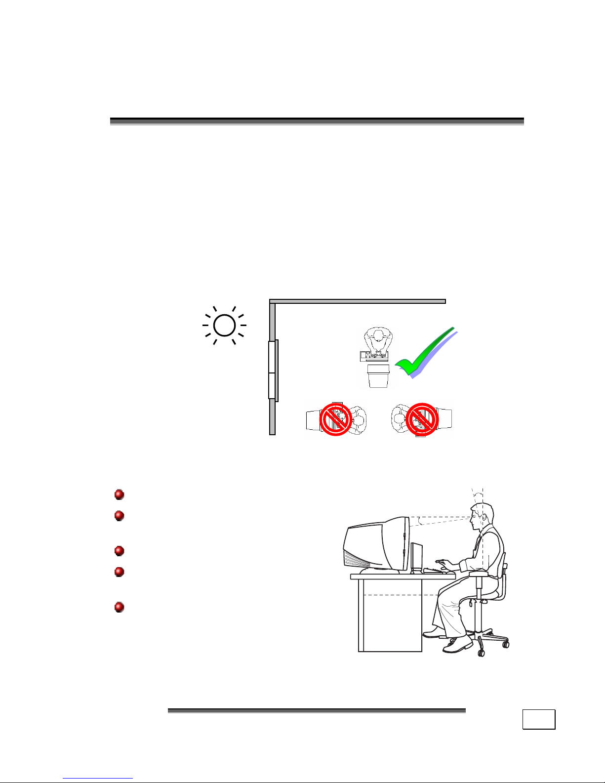
Ensure that the monitor is set up in such a way that reflections, glare and light/darkness contrast are avoided (no matter how attractive the look out of the windows might be).
Hand rest: 2” – 4”
Top line of screen at eye level or
slightly below
Viewing distance: 20” – 27.5”
Legroom (vertical):
minimum 25.5”
Legroom (horizontal):
minimum 23.6”
0-15•
50-70 cm
-(20-28 inches)0-15•
Page 18

S
S
EETTTTIINNGG
U
U
PP
&
&
G
G
EETTTTIINNGG
S
S
TTAARRTTEED
D
12
WORKING IN COMFORT
Take regular breaks from the work at your
screen to prevent tenseness and exhaustion.
Sitting in one position for long periods can be uncomfortable.
To minimize the potential for physical discomfort or injury,
it’s important that you maintain proper posture.
• Overall: Change your position frequently and tale regu-
lar breaks to avoid fatigue.
• Back: While sitting at your work surface, make sure
your back is supported by the chair’s backrest in erect
position or angled slightly backwards.
• Legs: Your thighs should be horizontal or angled
slightly downward. Your lower legs should be near a right
angle to your thighs. Your feet should rest flat on the
floor. If necessary, use a footrest, but double check that
you have your seat height adjusted correctly before getting a footrest.
• Arms: Your arms should be relaxed and loose, elbows
close to your sides, with forearms and hands approximately parallel to the floor.
• Wrists: Your wrists should be as straight as possible
while using the keyboard, mouse or trackball. They
should not be bent sideways, or more than 10 degrees up
or down.
• Head: Your head should be upright or tilted slightly
forward. Avoid working with your head or trunk twisted.
Page 19

S
S
EET
T
--U
U
PP
L
L
OOCCAATTIIOON
N
13
SET-UP LOCATION
• Keep your PC and all units connected to it away from
moisture, dust, heat and direct sunlight. Failure to
observe these instructions can lead to malfunctions or
damage to the PC.
• To prevent damage to your PC from a fall, place and op-
erate the PC and all connected units on a stable, bal-
anced and vibration-free surface.
AMBIENT TEMPERATURE
• The PC can be operated at an ambient temperature of
between +41° and +95° F and at a relative humidity of between 30% and 70% (without condensation).
• When powered off, the PC can be stored at temperatures
between –40° and +158° F.
Page 20
S
S
EETTTTIINNGG
U
U
PP
&
&
G
G
EETTTTIINNGG
S
S
TTAARRTTEED
D
14
FRONT CONNECTORS
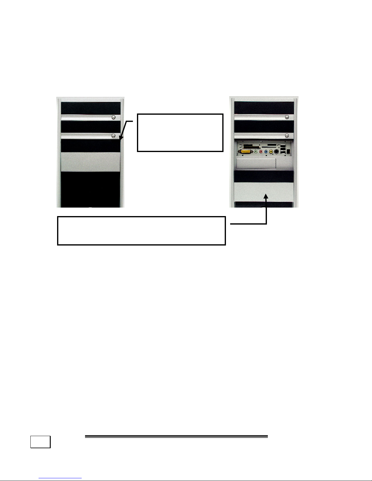
Here is how you can access the (optional) card reader and
some further connectors on the front of your PC casing.
(Diagram the same)
Please press this
button to slide
down the cover.
Push carefully the cover up to hide the
card reader and the connectors.
CD-RW
DVD-ROM
Connect XL
CD-RW
DVD-ROM
Page 21
C
C
AABBLLIINNG
G
15
C
C
OONNNNEECCTTIINNG
G
For a better guidance, open up the left inner page of
the cover with the drawings to find the location of the
described connections.
Note: The devices listed are not necessarily
included with your PC.
CABLING
Please follow the instructions below in order to correctly connect your PC:
• Arrange cables in such a way that no one can tread on or
trip over them.
• DO NOT place objects on the cables.
• To avoid damage to your PC, connect your peripherals
(e.g., keyboard, mouse and monitor) while your PC is
powered off. Some devices can be connected while your
PC is in use. These devices usually have a USB or IEEE
1394 connector. Please follow the appropriate instructions
for each device.
• Keep the PC at least one meter (approximately three feet)
away from high frequency and magnetic interference
sources (e.g., televisions, loudspeaker cabinets, mobile
telephones, etc.) in order to avoid malfunctions and/or
loss of data.
• To avoid EMC issues, make sure that all devices are con-
nected to each cable or that cables not in use are removed from the computer.
• Please note that only shielded cables shorter than
3 meters (9.84 ft) should be used for the LPT, COM, USB,
IEEE 1394, audio, video and network interfaces with this PC.
Page 22

S
S
EETTTTIINNGG
U
U
PP
&
&
G
G
EETTTTIINNGG
S
S
TTAARRTTEED
D
16
• The connection of devices is limited to equipment that complies
with EN60950 “Safety of information technology equipment” or EN60065 “Audio, video and similar electronic apparatus. Safety requirements”.
Note: You only need to connect those compo-
nents to your computer you require. If you do
not have the described device (e. g. printer)
you may skip the respective item and carry it
out later, if necessary.
CONNECTING THE MONITOR
DDrraawwiinngg rreeffeerreennccee:: WW
• If your graphics card has two blue VGA sockets, you
can use either port to connect to the monitor.
• Because of its asymmetric form the plug only fits into
the socket in one position.
1. Connect the data cable of the monitor to the blue
socket on the graphics card. If necessary, remove
the white guard-ring on the monitor plug and ensure
that the plug and socket mate together precisely.
2. Hand-tighten the screws on the monitor cable.
CAUTION! Your PC monitor is preconfigured for a
screen resolution of 1024 x 768 pixels and an
optimal refresh rate. If your monitor does not
support these settings it may become damaged
or malfunction during use.
Page 23

C
C
AABBLLIINNG
G
17
You can change the screen resolution and configuration of your
manual as follows (See also your monitor's User Manual):
1. Once you have powered on the PC, press the F8
key (see page 37) to select Safe Mode.
If you don’t hit the F8 key on time, you won‘t
see the start menu which gives you the option
to run in Safe Mode. Reboot your PC and retry if you have missed this.
2. Select Display Properties to designate the
screen resolution for your monitor.
Then you can adjust the „Display Features“ to your monitor.
CONNECTING A PS/2 KEYBOARD
DDrraawwiinngg rreeffeerreennccee:: RR
Connect the keyboard to the left, blue PS/2 port.
If you want to connect a USB Keyboard please follow the instructions below.
CONNECTING A USB KEYBOARD
DDrraawwiinngg rreeffeerreennccee:: EE
Connect the USB keyboard to the USB port.
CONNECTING A PS/2 MOUSE
DDrraawwiinngg rreeffeerreennccee:: OO
Connect the mouse cable to the right, green PS/2 port.
If you want to connect a USB mouse please follow the instructions below.
CONNECTING A USB MOUSE
DDrraawwiinngg rreeffeerreennccee:: EE
Connect the USB mouse to the USB port.
Page 24

S
S
EETTTTIINNGG
U
U
PP
&
&
G
G
EETTTTIINNGG
S
S
TTAARRTTEED
D
18
CONNECTING PARALLEL DEVICES
DDrraawwiinngg rreeffeerreennccee:: PP
• Because of its asymmetric form the plug only fits into the socket in one position.
1. If you wish to connect a printer with a parallel (25pin) connecting cable, connect the printer cable
from your printer to the red printer socket P on the
rear of your PC.
2. Hand-tighten the screws.
If you wish to use a scanner, which also connects to the PC
via the parallel interface, follow the instructions above. With
the PC parallel port in use, the printer can be connected directly to the scanner. You will have use of both devices if
they are connected in this manner.
CONNECTING SERIAL DEVICES
DDrraawwiinngg rreeffeerreennccee:: SS
• Because of its asymmetric form the plug only fits
into the socket in one position. Hand-tighten the
screws.
1. In order to connect an external modem, card
reader or other serial device, connect the serial cable with the turquoise-colored connection socket on
the rear of your PC.
2. Hand-tighten the screws.
Page 25

C
C
AABBLLIINNG
G
19
MODEM/ISDN CONNECTION
DDrraawwiinngg rreeffeerreennccee:: ZZ
If your computer is fitted with a modem or ISDN card, connect the matching end of the communications cable with port
Q of your PC. The socket is identified as Line. Plug the other
end into of the communications cable to the telephone wall
socket or into the network port provided.
MODEM
The modem cable has an RJ11 plug, which is plugged into
the modem of your PC, and a TAE plug, which fits an Ncoded, analog telephone socket. For further information
please refer to the Modem section.
ATTENTION! Please observe that the modem
may only be connected to an analog telephone
line. The connection of a digital system (ISDN
etc.) to an analog telephone line can possibly
cause damages to the modem or the connected
devices and the telecommunication network.
ISDN
The ISDN cable has RJ45 plugs at either end. It makes no
difference which end is plugged into which socket.
1. Connect the matching plug of the enclosed communication cable to jack Z of your computer. Usu-
ally the jack is marked with „Line“.
2. Then connect the other plug to the telephone or
ISDN outlet.
ATTENTION! Operate the ISDN unit only
with digital telephone systems. This prevents
an inadmissible operation possibly causing
damages to the unit or the connected devices.
Page 26

S
S
EETTTTIINNGG
U
U
PP
&
&
G
G
EETTTTIINNGG
S
S
TTAARRTTEED
D
20
LAN CONNECTION
DDrraawwiinngg rreeffeerreennccee:: QQ
LAN (network) connecting cables depend on the network
topology, i.e. whether for optical fiber or Ethernet.
According to the features your PC can be equipped with a network connection, in order to prepare it for network operation.
The network cable usually has two RJ45 plugs so that it is
unimportant which plug is connected to which jack.
1. Connect the one plug of the cable to the PC jack.
2. Connect the other plug to the other PC or
hub/switch.
For further information refer to chapter „The Network“
starting at page 59.
CONNECTING DEVICES TO THE GAMING PORT
DDrraawwiinngg rreeffeerreennccee:: GG
The multi-pin, orange gaming port G can be used to connect
game controllers (joystick, game-pad, steering wheel
etc.) as well as Game-to-MIDI-adapters.
• Because of its asymmetric form the plug only fits
into the socket in one position. Hand-tighten the
screws.
1. Connect the plug of the respective device with the
turquoise colored jack in the rear of your PC.
2. Then tighten the screws of the serial cord by hand.
CONNECTING SPEAKERS/AUDIO OUTPUT
DDrraawwiinngg rreeffeerreennccee:: HH
Connect your headphones or active speakers by plugging
the cable with the 3.5 mm stereo jack plug into the green
socket (reference H).
Page 27

C
C
AABBLLIINNG
G
21
PCS WITH SURROUND SOUND
If your PC is equipped with it the following connection is required:
1. Connect the front speaker to the green socket
(reference H).
2. Connect your rear speaker to the Rear connector (H2).
3. Your center speaker or subwoofer can be connected to the socket Center/Subwoofer (H3).
4. In order to use the (optional) digital audio outlet
plug the cinch cable in the jack at location U and
connect the cable with an audio device with a digital cinch inlet according to the SPDIF standard.
CONNECTING A SOUND SOURCE/AUDIO INPUT
DDrraawwiinngg rreeffeerreennccee:: JJ
This port is used to accommodate a connecting cable for external audio sources (i.e. stereo system, keyboard/synthesizer).
1. Connect the cable with the 3.5 mm stereo jack
plug to the light-blue colored socket (reference J).
2. If you want to record a digital audio source use
the audio input T. A SPDIF-Cinch cable will also
be necessary.
CONNECTING A MICROPHONE
DDrraawwiinngg rreeffeerreennccee:: II
1. You can use the pink socket I to connect a micro-
phone with a 3.5 mm mono jack plug.
2. Position the microphone in such a way that it does
not point directly at the speakers. If you hear
feedback, characterized by loud whistling noises,
reposition the microphone until the sound stops.
CONNECTING ANTENNAS TO YOUR TV-/ RADIO CARD
DDrraawwiinngg rreeffeerreennccee:: YY,, YY22
If your PC is provided with a TV-/Radio tuner card you have
to connect antennas.
Page 28

S
S
EETTTTIINNGG
U
U
PP
&
&
G
G
EETTTTIINNGG
S
S
TTAARRTTEED
D
22
With a 75 Ohm coaxial antenna cable you are able to receive
TV and Radio stations.
1. Connect your Radio-/TV-Tuner card (Y) with an
aerial socket for radio reception. If you don’t have
such socket use the antenna shipped with your PC.
2. Connect your Radio-/TV-Tuner card (Y2) with an
aerial socket for TV reception.
CONNECTING THE PC TO A TELEVISION
DDrraawwiinngg rreeffeerreennccee:: VV ((CCiinncchh)),, VV22 ((SS--VViiddeeoo))
If your computer’s VGA card is equipped with a TV-Out
socket you can establish a connection to a TV.
1. Connect your PC and your television with the cord
required for your TV.
CONNECTING A RECORDING SOURCE / VIDEO INLET
DDrraawwiinngg rreeffeerreennccee:: KK ((CCiinncchh)),, LL ((SS--VViiddeeoo))
Your PC may be fitted with a TV-input, depending on the
model you selected. You can transfer data from your video
camera to your PC and edit the images using this connection.
1. Connect the plug of the cord to the jack (position U).
USB/IEEE 1394
• Usually this type of device can be connected while the
PC is in use, but it is a good idea to read the manuals
of all the devices you connect to your PC before installing them.
• The voltage outputs of your PC for IEEE 1394 (6-pole)
as well as for USB are protected by a fuse (limited
power source according to EN60950). This ensures
that a malfunction of the PC will not damage the peripheral devices connected to the respective jacks.
CONNECTING IEEE 1394 (FIRE WIRE) DEVICES
DDrraawwiinngg rreeffeerreennccee:: FF ((66--ppoollee)),, FF22 ((44--ppoollee))
Page 29

C
C
AABBLLIINNG
G
23
CONNECTING USB DEVICES
DDrraawwiinngg rreeffeerreennccee:: EE
You have a choice of several connection sockets.
It does not matter which you use.
1. If you wish to use a printer, scanner or other
device with a USB port, connect the cable to the
USB socket on your PC.
For detailed information refer to the chapters USB (starting on page 57) or IEEE-1394 (starting on page 58).
CONNECTING THE POWER SUPPLY
DDrraawwiinngg rreeffeerreennccee:: XX
Finally, connect the power supply to your PC and monitor, by
plugging the power cord into the outlet. Observe the following safety precautions:
• The power socket must be in the vicinity of the PC
and within reach of the power cables. DO NOT
stretch the power cables tightly to reach a
power socket.
• In order to disconnect your PC from the power source,
or set the PC to voltage free, remove the power cord
from the socket. Use only the supplied power cord.
• To provide additional protection against electric
shock, power surges, lightning strikes, or other electrical damage to your PC, we recommend the use of a
surge protector.
• If you are using an extension cord, ensure that the
cord meets your local safety requirements. If in
doubt, ask an electrician.
• The power supply unit has an On/Off switch (X2) that
can be used to power off the PC. When the switch is
Off no power is being consumed.
DO NOT Start Your PC Yet!
First, read the following section to find out what you need to
know in order to get started.
Page 30

S
S
EETTTTIINNGG
U
U
PP
&
&
G
G
EETTTTIINNGG
S
S
TTAARRTTEED
D
24
G
G
EETTTTIINNGG
S
S
TTAARRTTEED
D
The software on this PC comes fully pre-installed. You do
not have to load any of the CD's supplied. With many programs (e.g., telephone-CD's or encyclopedias), however, it is
necessary to insert the corresponding CD in order to call up
the data which is stored on it. The software will ask you to do
this as necessary. Once you have made all the connections
and secured the necessary connectors you can turn on the
monitor, the other peripherals and finally the PC itself.
Step 1
1. Power on the monitor and your peripheries.
2. Power on your PC by pressing the Switch (drawing
reference X2) to position [1].
Attention! Even with switch set to off mode [0],
some parts of the PC remain under voltage. To completely disconnect the PC from all power sources, unplug the power cord from the socket.
3. Press Main Power Switch (drawing reference N)
briefly to start loading the operating system.
Explanation:
The PC starts and now goes through a number of phases:
Note: Ensure that there is no bootable CD (e.g.
the Recovery-CD) in the CD-ROM drive. Such
disks will prevent the operating system from
loading directly off the hard drive.
The operating system is loaded from the hard disk. During
the initial set-up, the loading process takes slightly longer than
normal to register the operating system and the individual
components completely. Your operating system is finished
loading when a welcome screen is shown on your display.
Page 31

C
C
AABBLLIINNG
G
25
Step 2
Follow the instructions on the screen. Dialogue boxes will
explain any steps that need to be taken. The greeting procedure will guide you through the following screens and dialogues.
Should you have any questions just click on
.
Mouse Familiarization Program
Explanation:
Use the mouse familiarization program to learn how to operate the mouse.
License Agreement
Explanation:
Please read through the license agreement carefully.
It contains important legal information on the use of your
software.
In order to see the full text, use the mouse and the scroll
bar to move downwards until you have reached the end of
the document. You accept the agreement by clicking on
the I accept the agreement option field. Only by doing
so will you be entitled to use the product under lawful
terms and conditions.
Step 3
After the login procedure the Windows® desktop appears on
your screen. This can be adjusted so that the screen of your
computer looks different. The basic operation, however, is
ensured.
Page 32

S
S
EETTTTIINNGG
U
U
PP
&
&
G
G
EETTTTIINNGG
S
S
TTAARRTTEED
D
26
SHORT DESCRIPTION OF THE WINDOWS
®
DESKTOP
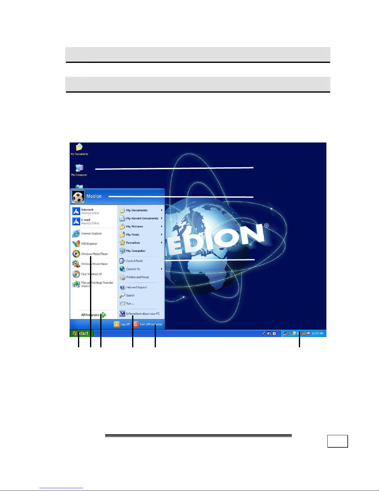
(The respective illustration is shown on the next page.)
The Start button
Click once on this button with your left mouse key to call the illustrated start menu.
Program bar
The most commonly used programs are listed here. The operating
system recognizes them automatically. If you press the right mouse
key on an entry you can determine which entry is kept and which is
deleted from the list. The program associated with the entry will not
be deleted.
All programs
Here you find the entries to every program installed on your PC.
Here, too, you can edit entries with the right mouse key.
Information about your PC
Click on this button once with the left mouse key to receive important information about your PC as well as valuable hints and additional assistance.
Switching off
Click on this button with the left mouse key to switch off the PC.
Task bar
Here you receive information and status reports about the operating system and the running programs.
„Icons“ on the „Desktop“
Icons are program links used to start the respective programs. A
double click (press the left mouse key quickly twice) on the sym-
bol starts the application.
The Desktop includes almost the complete screen and is the filing
area for those entries or other links you would like to access
quickly.
Page 33
S
S
HHOORRTT DDEESSCCRRIIPPTTIIOONN OOFF TTHHEE
W
W
IINNDDOOWWS
S
®
®
D
D
EESSKKTTOOP
P
27
Logged in user
This shows the logged in user. The image is changed by clicking on it.
Control Panel
This is the central control of your computer. Here you are able to
configure your computer at will. However, you should read about
the implications of possible changes in „Help and Support“.
Page 34

S
S
EETTTTIINNGG
U
U
PP
&
&
G
G
EETTTTIINNGG
S
S
TTAARRTTEED
D
28
Page 35

29
CChhaapptteerr 33
Operation
Subject Page
The Keyboard …………………………………………… 31
The Hard Drive ………………………………………… 39
The Card Reader ……………………………………… 41
The Optical Drive (CD/DVD/CDRW) ………… 42
The Graphics Card ……………………………………… 52
The Radio-/TV- Tuner Card ………………………
55
The Sound Card ………………………………………… 55
The USB Port ……………………………………………… 57
IEEE 1394 (Fire Wire) ……………………………… 58
Network ……………………………………………………… 59
Modem ……………………………………………………… 63
Page 36

O
O
PPEERRAATTIIOON
N
30
Page 37
T
T
HHEE
K
K
EEYYBBOOAARRD
D
31
O
O
PPEERRAATTIIOON
N
THE KEYBOARD
This section contains useful information on using the
keyboard. All diagrams are schematic.
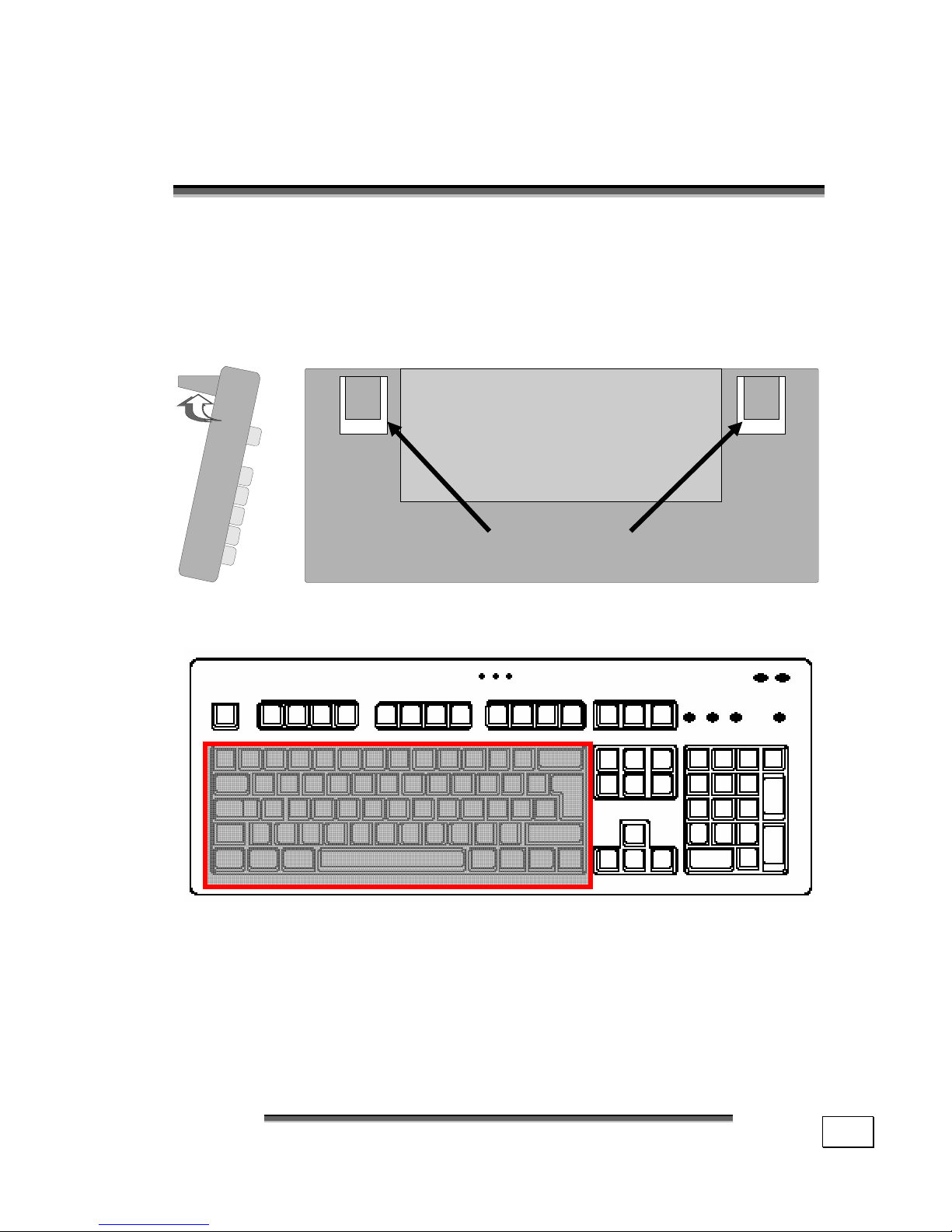
On the base of the keyboard are two folding feet that let you
adjust the angle of the keyboard.
THE QWERTY KEYBOARD
The QWERTY keyboard consists of keys with numeric, alphanumeric and special characters. The keyboard layout is generally the same as that of a typewriter, with some additional
keys added for specific computer functions.
Adjustable Feet
Page 38
O
O
PPEERRAATTIIOON
N
32
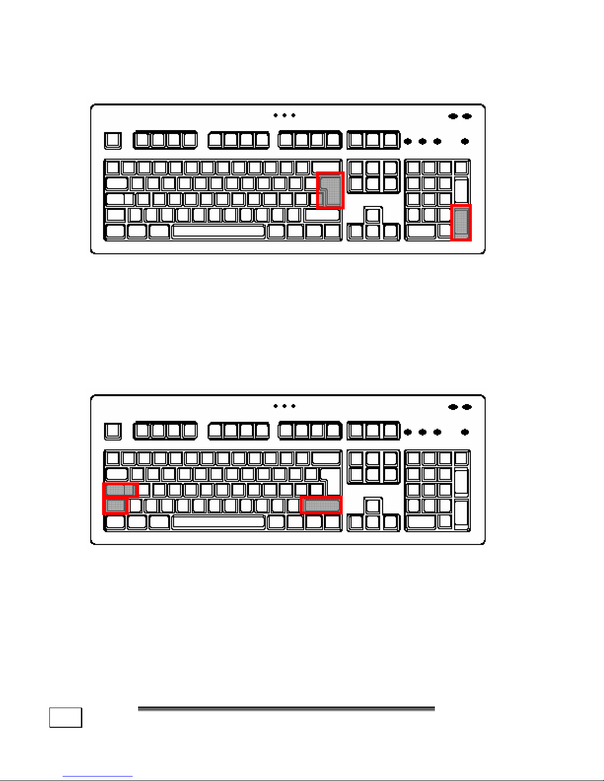
THE RETURN KEY
The RETURN (or ENTER) key is identified by an arrow pointing to the left. Press ENTER to confirm preset or manually
entered commands. In application programs, such as a word
processing program, ENTER moves the cursor to the start of
the next line. The ENTER key in the number pad has the
same function as the RETURN key.
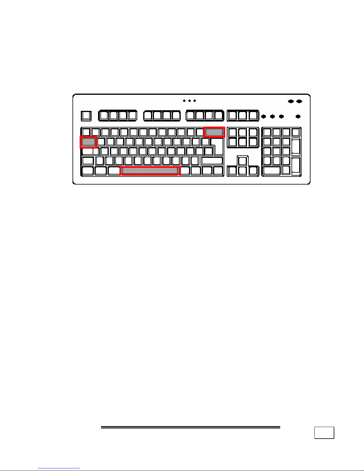
THE SHIFT AND CAPS-LOCK KEYS
There are two SHIFT keys, which are identified by a wide
arrow pointing upward. When the SHIFT key is pressed, letters entered are shown as capitals. For other keys the characters shown in the top section of the key will be displayed.
The CAPS-LOCK key is identified by a wide arrow pointing
downward. When this key is pressed it has the same effect
as the SHIFT key being held down continuously.
Page 39
T
T
HHEE
K
K
EEYYBBOOAARRD
D
33
When the CAPS-LOCK is operational the middle status LED
lights. The CAPS-LOCK function is deactivated by pressing
the SHIFT key.
SPACE, TAB AND BACKSPACE KEYS
The BACKSPACE key is identified by a thin arrow pointing
left. When it is pressed the character to the left of the cursor
is deleted. If there are any characters to the right of the cursor, then these are moved one space to the left with the cursor.
The SPACEBAR is the long, unmarked key on the bottom
row of the keyboard. Press it to create a space between
characters.
Two opposing arrows identify the Tab key, one on top of the
other. In word processing TAB normally moves the cursor a
certain distance to the right or, when the shift key is pressed
simultaneously, to the left. The TAB function may, however,
vary according to the program used.
Page 40
O
O
PPEERRAATTIIOON
N
34
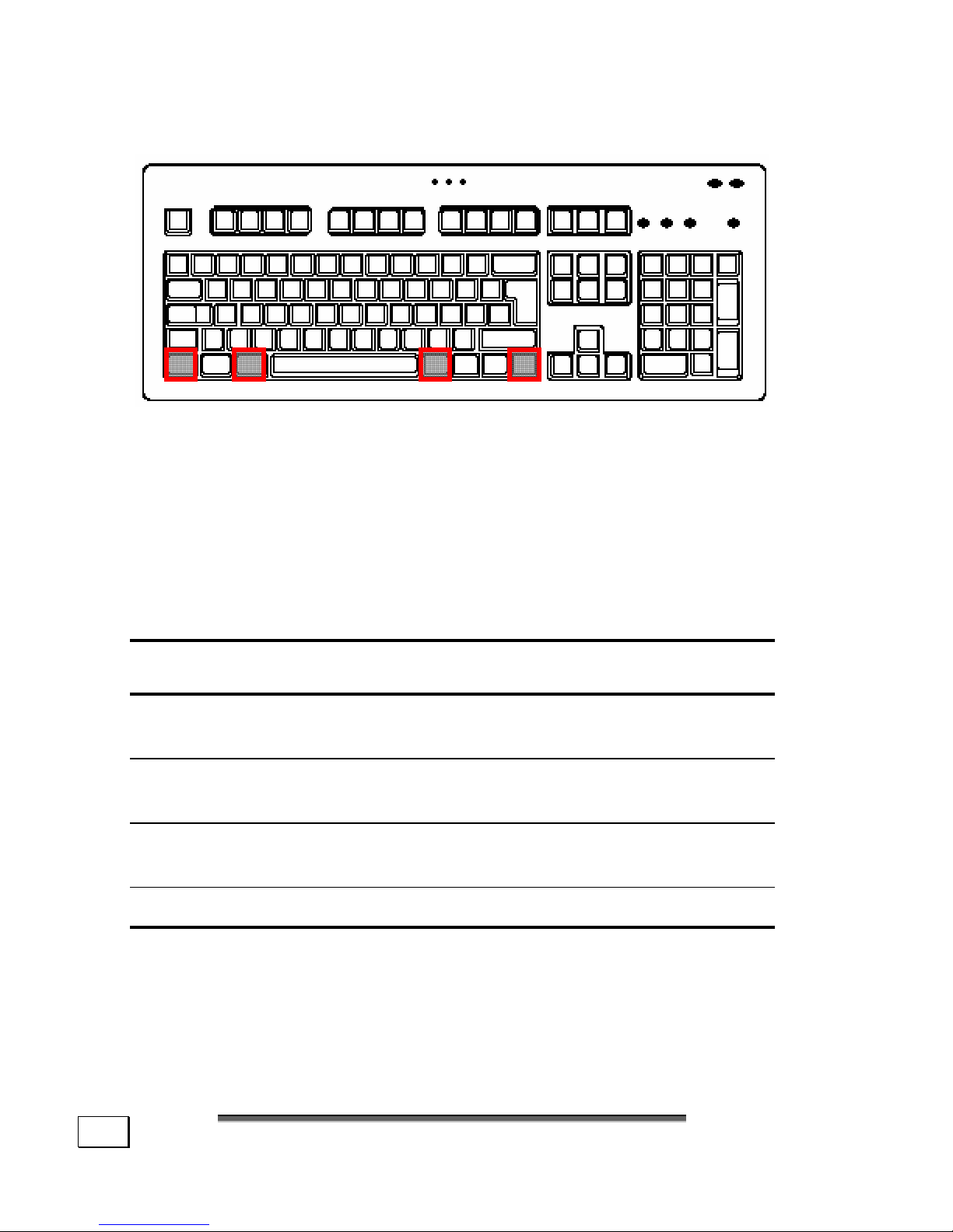
THE ALT AND CTRL KEYS
The left Alt key performs certain functions in conjunction with
other keys. The application program determines these functions. In order to enter a combination of keys that include the
Alt key, hold the Alt key down while pressing the other key.
The right Alt key operates in a similar way but selects certain
special characters. The Ctrl key, like the Alt key, carries out
program functions.
Useful key combinations (software-dependent):
Key
Combination
Function and Description
Alt + F4
As a rule ends the program selected or
closes the window opened.
Alt + Print screen
Copies the image of the window currently active to the clipboard.
Shift + 2
Generates the @ character required for
e-mails (pronounced: at).
Ctrl + Alt + Del System properties are launched.
Page 41
T
T
HHEE
K
K
EEYYBBOOAARRD
D
35
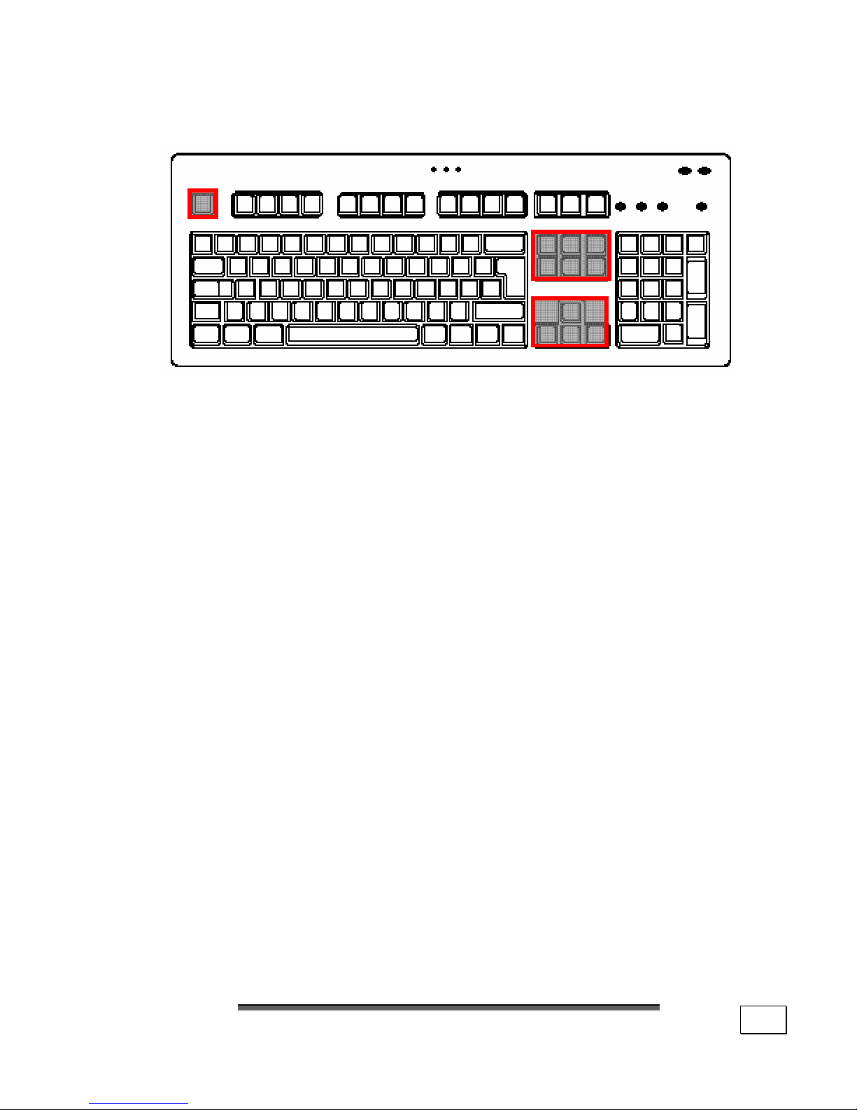
CURSOR CONTROL KEYS
The four directional keys, also known as arrow keys, are
responsible for controlling the cursor on the screen. The cursor moves in the direction shown on the key.
The Home key moves the cursor to the start of a line and
the End key to the end of the line.
The Page and Page keys scroll one page on in the corresponding direction.
The functions described are dependent upon the application
program and may differ from program to program. In combination with the control key (Ctrl) the cursor control keys
may offer additional functions.
The Insert key changes the keyboard to the insert character
mode. In insert mode the data are entered at the cursor position and all subsequent characters are shifted to the right.
The insert mode remains active until the Insert key is
pressed again.
The Delete key removes the character to the right of the
cursor. All other characters to the right of the cursor shift
one space to the left.
The Escape (ESC) is used to leave a program or programspecific menu. Its precise function is dependent upon the
software used.
Page 42
O
O
PPEERRAATTIIOON
N
36
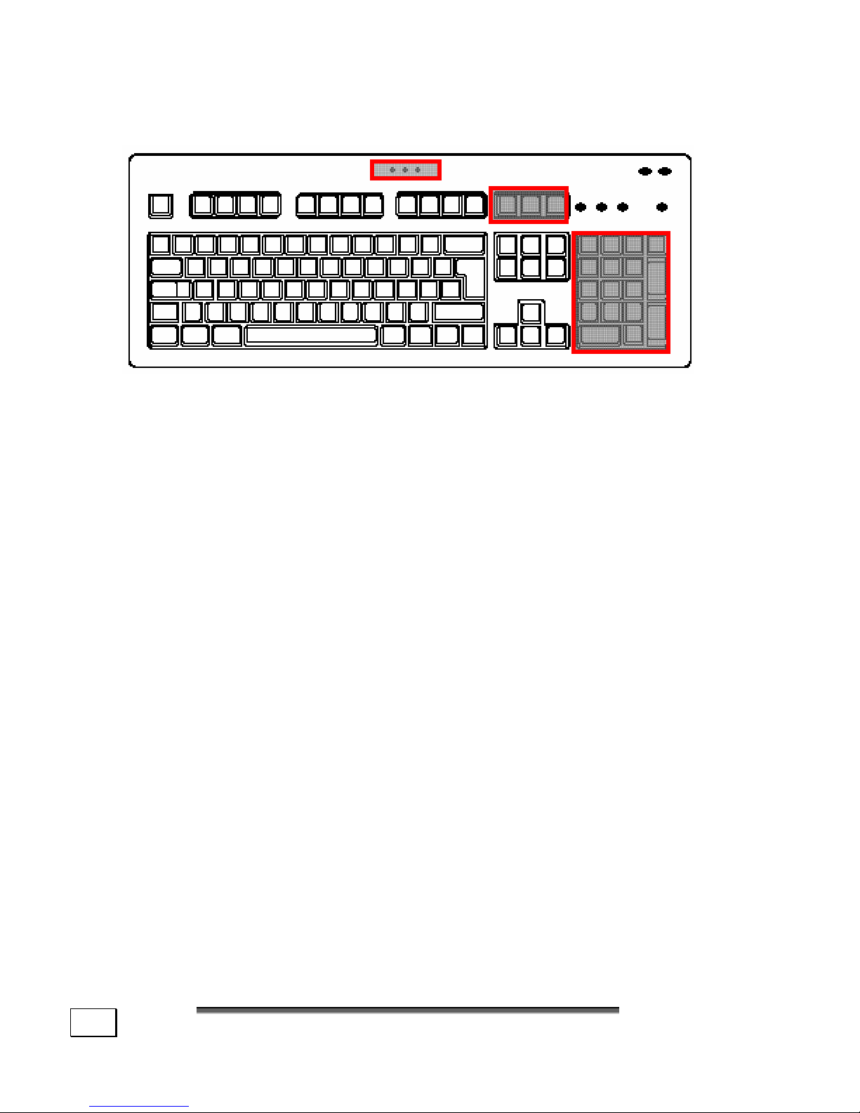
THE NUMBER AND CURSOR PAD
The number pad is used for rapid input of figures and numerical operations. The number pad is not designed for numerical touch-typing.
Pressing the <NUM> key activates the number pad, illuminating the NUM LOCK indicator light. If the NUM LOCK
indicator is not lit, then the cursor pad is active and the key
functions are the same as for the control pad.
The Print Screen key allows a printout (hardcopy) of the
screen content on a printer (where connected). This does not
apply, however, to all characters, and no graphics are output
to the printer. In addition this key only works under MS-DOS
with the corresponding setting. Under Windows the screen is
copied as a graphic to the clipboard.
The Break key allows data output on-screen to be halted
and restarted by the operation of any other key. This is used
in the MS-DOS operating system if you wish to output text
from the screen that is longer than one screen page. If the
<Break> key is operated when the Ctrl key is pressed, then
commands or programs currently being executed, such as
screen output, will be interrupted.
The Scroll lock key has no function in the MS-DOS operating
system. Some Windows software uses this key to freeze the
cursor at a certain position. If the key is pressed once, then
the Scroll lock function is activated. The corresponding Display
lights. The function is switched off by pressing the key again.
Page 43
T
T
HHEE
K
K
EEYYBBOOAARRD
D
37
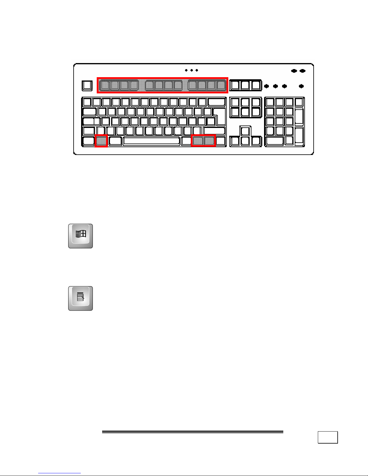
THE FUNCTION AND WINDOWS KEYS
The F1 to F12 keys in the top row of the keyboard are known
as Function keys. The function keys have no generally ap-
plicable function and are assigned differently by each piece of
software. Instructions on the assignment of these keys will
be found in the manuals of the respective software programs. Help is usually called up via the F1 key.
The left and right Windows keys (with the Windows
banner) are used to call up the Windows opening
menu.
Tip: Press this key simultaneously with the E key to start
Windows Explorer; pressing simultaneously with the
Pause key calls up the Device Manager.
The Applications key corresponds to clicking the right
mouse button. In Windows, for example, this key
opens the context menu for the work area.
Page 44
O
O
PPEERRAATTIIOON
N
38
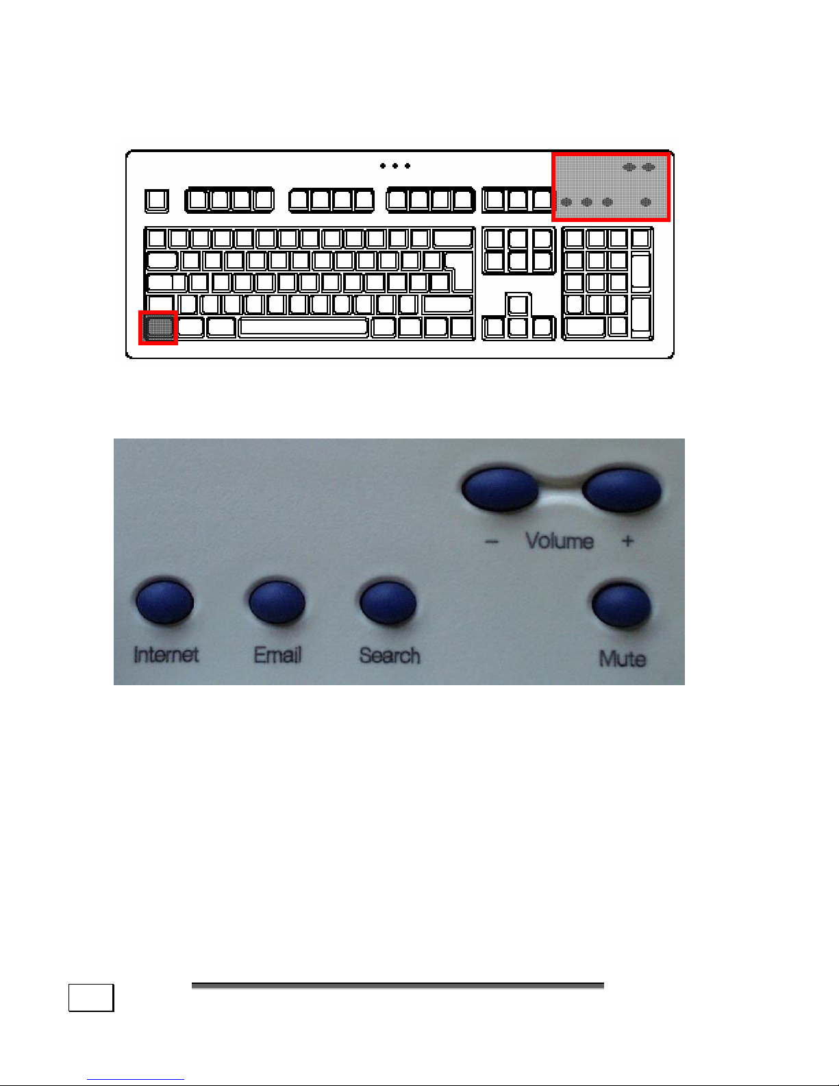
MULTIMEDIA FUNCTIONS
(Diagram the same)
Some keyboards are provided with multimedia keys. These
keys have the following functions:
The Internet key will launch your Internet browser application.
The Email key will launch your Email application.
The Search key will launch your predefined search engine.
The Mute key will turn off PC sound.
With Volume +/- you can adjust the system volume.
Page 45
T
T
HHEE
H
H
AARRDD
D
D
RRIIVVE
E
39
THE HARD DRIVE
The hard drive is the main storage medium combining large
storage capacity and rapid data access.
The hard drive contains the operating system of the computer,
other application programs and backup files. These programs
and files are pre-installed on your PC, so you may note that
some of the space on your hard drive is already taken.
The Windows operating system cannot use the full capacity
of the hard drive, which means that there will be a difference
between the capacity that the BIOS displays and what the
operating system displays. The operating system of the PC,
further application programs and backup files are located on the
hard drive and reduce its total capacity.
The hard drive is addressed as drive C, D and E.
Never switch off the computer while the busy
indicator is lit since this may result in loss of
data.
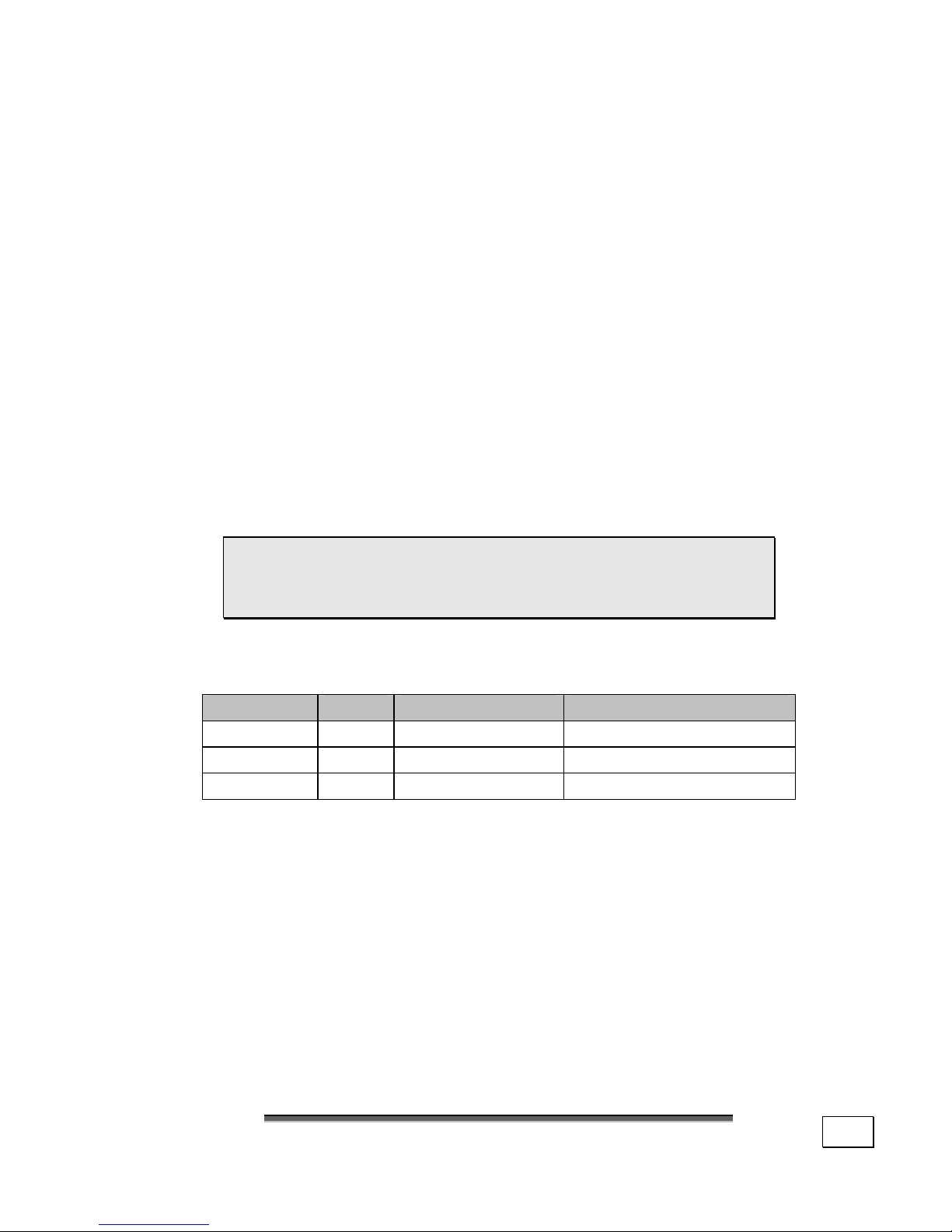
Usually your hard disk is divided into more partitions, but
there can also be some minor variations.
Partition Drive Type Capacity (approx.)
Boot C: NTFS 60%
Backup D: NTFS 30%
Recover E: NTFS or FAT32 10%
In your first partition (Boot) you will find your operating sys-
tem, application programs and the users’ documents and
settings.
The second partition (Backup) serves for data security and
contains additional drivers and tools.
The third partition (Recover) contains the copies of your
Windows-installation in the delivery state.
Page 46

O
O
PPEERRAATTIIOON
N
40
IMPORTANT DIRECTORIES
In the following we listed the most important directories describing their contents.
Attention! Do not delete or modify these di-
rectories or their contents since data could be
lost or the functionality of the system could be
at risk.
C:\ The master directory of drive C: includes important
files required to start Windows. In the factory setting
these files are hidden for safety reasons.
C:\Programs As the name suggests, in this directory pro-
grams install the files belonging to the application.
C:\Windows The main directory of Windows.
This is where the files of the operating system are
saved.
C:\Documents and Settings This folder includes the set-
tings and documents of all the PC users.
D:\Driver This folder includes the drivers required by your
computer (pre-installed).
D:\Tools Here you find additional programs and other docu-
mentation for your PC.
E:\Recover Here the backup files are located enabling you
to recover the factory setting (see page 75).
Page 47
T
T
HHEE
C
C
AARRDD
R
R
EEAADDEER
R
41
THE CARD READER
(Diagram the same)
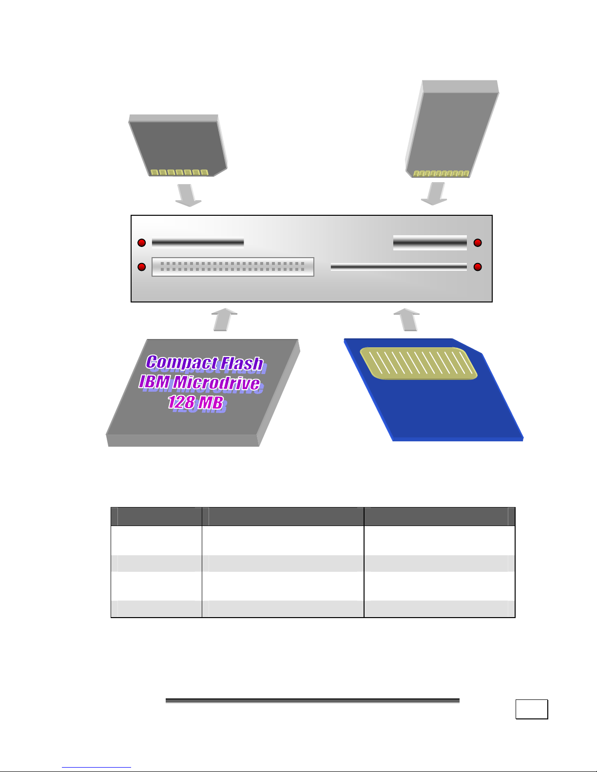
If your PC is provided with a Card Reader (drawing reference: C), you can handle different memory card types.
The following table refers to the use of the Card Reader:
Slot Card type Contacts
Top, left
SD (Secure Digital)
MMC (MultiMediaCard)
point to bottom
Top, right Memory Stick point to bottom
Bottom, left
CF (Compact Flash)
IBM
®
Microdrive
point to front
Bottom, right SmartMedia point to top
If a card is inserted, a free drive will be assigned by Windows
®
and the LED next to the slot is lit.
SD / MMC Memory Stick
Compact Flash / IBM® Microdrive SmartMedia
Page 48

O
O
PPEERRAATTIIOON
N
42
THE OPTICAL DRIVE
Depending on the model, your PC will be fitted with a CDROM, a CD-RW, a DVD-drive or a combination of those
drives. The schematics and features for each drive may vary.
NOTE: This section describes the CD-ROM
drive. Operation of a DVD or CD-RW drive is
basically the same.
With a CD-ROM drive, data can be read or audio CDs played.
Compact disks can store large quantities of data and offer
relatively rapid access to data.
LOADING A DISK:
1. Press the eject button (drawing reference, B) on the
front of the CD-ROM-drive to open the tray.
2. Place the disk on the tray so that it lays flat with the label facing upward.
3. Press the eject button again to close the tray.
Many CD's start automatically when they are
inserted.
In order to access the CD via Windows Explorer, select the
letter corresponding to the drive. When accessing audio or
video disks (or audio or video files on conventional CDs) you
should use the media playback application pre-installed on
the computer. CD-ROM and DVD-ROM drives can play audio
CDs, but only the DVD-ROM drive can play DVD audio or
video disks.
Depending on the DVD audio CD and the software installed
you may also have to open a DVD player program. For further information on the subject DVD refer to page 43.
Page 49

T
T
HHEE
O
O
PPTTIICCAALL
D
D
RRIIVVE
E
43
HOW TO REMOVE A DISC:
1. Press the eject button (drawing reference, B) at
the front of the CD-ROM drive to open the drawer.
2. Remove the disc and store it in the CD cover in a
safe place.
While the computer is accessing the CD-ROM
drive, the corresponding LED display () is lit.
In this case do not try to remove the CD from
the drive.
THE CD-ROM/DVD DRIVE AS BOOT D DRIVE
The optical drives can be used for booting the operating system. If the PC does not boot, it is possible that autostart is
turned off in the BIOS or the CD is not bootable.
DVD TECHNOLOGY
The Compact Disc (CD) was introduced in 1982.
Who could imagined doing without the CD as a storage me-
dium for data, multimedia, computer games and video now?
A CD can hold up to 700 MB of data, but that amount is too
small to store a high-quality encoding of an entire feature
film. The DVD (Digital Versatile Disc) has the same dimensions as a CD but store more data at a greater density. In
some cases, both sides of the DVD can be used to store information. Furthermore, each side can contain two layers of
information (dual layer).
Thanks to high data density, the transfer speed is considerably higher than for a CD, so that a DVD drive with 6 times
speed can transfer considerably more data than a 6-speed
CD drive.
A DVD drive can also read both DVD-ROMs and CD-ROMs,
providing the user access to an astounding amount of media.
Page 50

O
O
PPEERRAATTIIOON
N
44
VARIOUS DVD FORMATS
Format Side A Side B Max. capacity
DVD-5 SL - 4.7 GB
DVD-9 DL - 8.5 GB
DVD-10 SL SL 9.4 GB
DVD-14 DL SL 13.2 GB
DVD-18 DL DL 17.0 GB
SL=Single Layer, DL=Dual Layer
DVD-VIDEO
Special characteristics of DVD-Video:
• Up to 8 hours of feature films on a single DVD.
• Up to 8 audio tracks and 32 subtitle tracks.
• Greater picture quality than VHS or SVHS.
• Time-frame navigation and picture stills.
• Selection of different camera angles in some media.
• Parental Control, in which certain scenes or an en-
tire film or rating of films can be made accessible only
to certain age groups. DVD players can, for example,
be set so that scenes or films which have not been
approved for younger audiences will not play.
In spite of the high storage capability of the DVD the data
must be extremely compressed in order for a complete feature film to be stored.
Page 51

T
T
HHEE
O
O
PPTTIICCAALL
D
D
RRIIVVE
E
45
REGIONAL PLAYBACK INFORMATION FOR DVD
The playback of DVD movies includes the decoding of MPEG2
videos, digital AC3 audio data and the deciphering of CSS
protected contents.
CSS (sometimes called copy guard) is the name of a data protection program incorporated by the movie industry as an action against illegal copies.
Among the numerous regulations for CSS licensees the most
important ones are the country specific playback restrictions.
In order to facilitate the geographically restricted release of
movies, DVD titles are released for certain regions.
Copyright laws require the restriction of each DVD movie to a
certain region (usually the region, in which it is sold).
DVD movie versions can be published in several regions but
the CSS regulations require that each CSS decipherable system may only be used in one region.
Attention: The decoding software included
with your PC may be changed for regional DVD
decoding up to five times, after which the
drive will only play DVD movies for the region
setting last entered. Changing the region code
after that will require factory resetting which is
not covered by warranty. If resetting is desired, shipping and resetting costs will be
billed to the user.
Page 52

O
O
PPEERRAATTIIOON
N
46
SUBJECTS CONCERNING THE CD-REWRITER
First you receive information on the so-called blank discs.
These media, requiring a CD rewriter (burner) to produce CDs
are called CD recordable (CD-R) or CD rewritable (CD-RW).
RECORDABLE/REWRITEABLE CDS (CD-R/CD-RW)
Normal CDs are pressed from a digital, glass master and
then sealed. In the case of blank CDs, the information is
burnt onto the CD with the laser of the CD-Rewriter. Therefore these disks are more sensitive than normal CDs. Please
avoid the following when using recordable/rewriteable disks
– especially blanks that have never before been used:
- radiation by direct sunlight (UVA/UVB)
- scratches and damage to the disk surface
- extreme temperatures
COLORS OF BLANK CDS
Blank CDs have a reflective layer (silver or gold) and a colored synthetic layer that is initially transparent. This synthetic layer is available in green or blue. The laser ray reflected back from the reflective layer hits the synthetic layer
and “burns” it, making it impassable for the laser ray. This is
how the information is imprinted onto the blank disk.
There is no one answer to the question about which color
combination is best as the medium (the blank CD), the writing device (CD-Rewriter) and the reading devices (CD-ROM,
hi-fi CD-player, Discman etc.) must harmonize together.
If you have problems reading a particular type of CD, we recommend you try a CD with a different colored synthetic layer.
Page 53

S
S
UUBBJJEECCTTSS
C
C
OONNCCEERRNNIINNGG TTHHEE
CCDD-
-
R
R
EEWWRRIITTEER
R
47
WHAT TYPES OF CDS CAN BE COPIED?
CD-ROM, CD-R and CD-RW drives have technical limits.
Copying all CDs perfectly is simply not possible. The source
CD-ROM drive and source CD both can cause problems in
duplication. We therefore recommend that before you permanently copy a CD you select the Simulation option. This
process does a test run of the reproduction before attempting
to burn data onto the CD.
But it is possible to make a damaged copy of a CD without an
error message being displayed. This can occur if there is data
or other information to protect the CD being copied “hidden”
between the tracks of the source CD. Using the software included with your PC, however, can help you make backup
copies of virtually any CD type.
The following table contains a list of CD types that can be
copied, and some remarks on how to make backup copies.
CD Type Comments
Audio If your drive is not a CD-R or a CD-RW drive,
a source CD-ROM drive is required that can
read digital audio data. Not all drives support
the extraction of digital audio data. You can
copy audio CDs under the "Disk-at-Once"
mode if the source CD-ROM drive is fast
enough.
Boot CD Using the software included in delivery, you
can make boot CDs.
Data CD 1/2
ISO 9660
Joliet
If no special formatting or copy-protection
methods have been used, you should be able
to copy this format without problems.
Extended
play CDs
CDs with a capacity of up to 80 Min./700 MB
can be generated. Not every drive works
with these CDs.
Page 54
O
O
PPEERRAATTIIOON
N
48
CD Type Comments
Mixed Mode Some CDs of this type can be copied without
problems while others can not. This is likely
because the formatting does not permit copies of CDs to be made or because there are
too many deviations from the CD standard.
PSX-CD Playstation™ games are supported.
UDF (Packet
Writing)
Some CD-ROM drives cannot read UDF-CDs.
If the CD-ROM drive is able to read Multi-
Session CDs, there should not be any problem
duplicating disks of this format. This format
requires the nero–InCD program.
WHAT DOES ... MEAN?
Boot CD See El Torito
Buffer
Underrun
Due to an empty intermediate buffer, the continuous flow of data to the CD-RW has been
interrupted and data has been lost.
CD-Extra CD-Format which contains audio and data-
tracks. As the audio data is at the beginning,
audio CD players can also play these CDs.
CD-R Recordable CD
CD-RW Re-writeable CDs
Disk at once
(DAO)
Writing the data in one process. This is important for copying music CDs so they are
true to the original.
El Torito Requires for Boot CDs. If a CD has been for-
matted with this format, a PC can be booted
from this CD if it has the appropriate BIOS
support. It does not support long filenames.
Page 55

S
S
UUBBJJEECCTTSS
C
C
OONNCCEERRNNIINNGG TTHHEE
CCDD-
-
R
R
EEWWRRIITTEER
R
49
Extraction (Audio-) Taking digital audio data from a CD-
ROM drive.
Finalizing If an audio CD has not been finalized, the CD
can only be played back in the CD-Rewriter.
Hi-Fi players cannot play back CDs which
have not been finalized.
Fixing In contrast to finalizing which finalizes the en-
tire CD, fixing is restricted to one session.
Hybrid-CD Format with two data systems: HFS (Apple
Mac) and ISO 9660 (other OS’)
HFS Hierarchical File System for Apple MacOS.
Image Image of a CD or a partition structure.
ISO 9660 CD-ROM file system specified in 1984:
Level 1 = 8.3 name convention (ABCD1234.EXT)
Level 2 = 8.3 name convention + special signs
Level 3 = up to 128 digits
Joliet ISO 9660-Format extended by Microsoft. File
names up to 64 digits whereby this extension is
only visible under Windows®9X/NT. Other systems only see the ISO 9660-Format.
Lead-In / Out
Marks the physical start and end of a ses-
sion. The TOC is saved in the Lead-In area.
Mixed Mode A CD containing both data and music tracks,
whereby the data is contained in the first
track and the music is contained in the second track.
Page 56

O
O
PPEERRAATTIIOON
N
50
MP3 MP3 (MPEG3) is a compression procedure
which reduces e.g. a CD music track to
approx. one tenth of its original size. Files
which have been compressed using this procedure can usually be recognized due to their
file extension *.mp3. To play back these files
you need a software decoder. A conventional
CD player is not capable of playing back
these music tracks.
Multi-Read CD-drives which have this capability are able
to read CD-RWs. This is achieved by amplifying the laser unit.
MultiSession
see session; To access other sessions of a
CD click the right hand mouse key on the
appropriate CD-ROM drive in the Explorer
and select “properties”. You can select a session from the file card “data carrier”.
On the fly This write procedure does not create an
Image-file. A small project file with file references is used to write the CD. To be able to
do this, you need a fast computer.
Packet
Writing
The CD is treated like a hard disk. You can save
(write) the data from an application directly
onto the CD. This only works from Windows
®
95
onwards. Another pre-condition is that the first
track of the CD contains a UDF-driver. This
driver is loaded automatically when the CD is
inserted into the drive.
PSX-CD CD for the Sony™ Playstation™. To operate
the PSX-CD-backup copies, the Playstation™
must be equipped accordingly.
Page 57

S
S
UUBBJJEECCTTSS
C
C
OONNCCEERRNNIINNGG TTHHEE
CCDD-
-
R
R
EEWWRRIITTEER
R
51
Sector Smallest addressable unit of a CD.
Session
A session includes all data which have been
burnt onto the CD in one writing process.
Only one data track can be written per session, however a number of audiotracks can
be written. Every CD can have a number of
sessions, but these CDs can only be read by
devices capable of reading multi-sessions.
TOC (Table of contents) Directory of tracks.
Track
On a music CD, one track is the equivalent to
one song. In the case of data it is a summary
of sectors of the same type to record data.
Track at
once (TAO)
On multi-session CDs, all tracks are written
onto the CD in one working process. The
TOC and the connections are written between the data blocks and cause a pause of
approx. 2 seconds between the songs.
UDF
(Universal
Disk
Format)
Platform-wide CD file system which is used in
the Packet Writing process. The required UDF
driver is always loaded from the CD and makes
it possible for CD writers and CD-Rewriters to
access the CD as it would a hard disk.
Extended
play CDs
By reducing the size of the distance between
tracks, the capacity of a CD can be extended.
You require special CD blanks (80 Min./
700MB) and a recorder, as well as matching
software which supports this. The products
included in delivery are capable of these tasks.
Unicode
16-Bit-digit set. The standard ASCII-set of
signs is saved in 8 Bit mode and therefore has
a limited scope, for example no Arabic letters.
Page 58
O
O
PPEERRAATTIIOON
N
52
THE GRAPHICS CARD
Your computer is fitted with an A.G.P. high performance
graphics card, one of the most technologically advanced and
best-equipped VGA cards available.
PERFORMANCE CHARACTERISTICS
A.G.P. (Accelerated Graphic Port)
High Performance Acceleration
Interactive Direct3D Acceleration
Video Acceleration for DirectDraw/DirectVideo, MPEG-1,
MPEG-2, DVD and Indeo
®
Video Technology
ACPI Power Management
CURRENT IMAGE PLAYBACK FREQUENCIES
The graphic card can, depending on the set resolution, display
vertical image playback frequencies of between 60 Hz and 240 Hz.
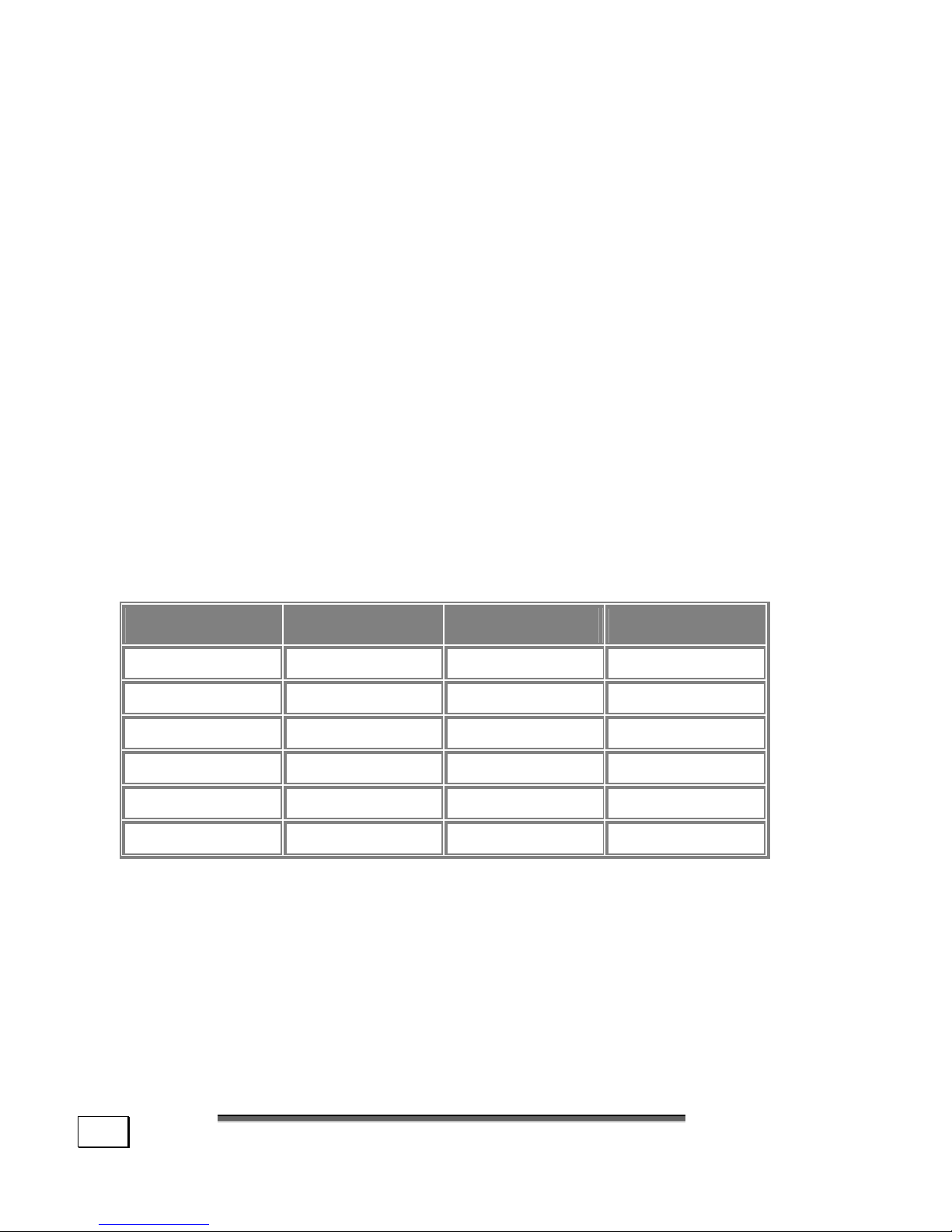
Resolution Colors Resolution Colors
640 x 480 8-, 16-, 32-bit 1600 x 900 8-, 16-, 32-bit
800 x 600 8-, 16-, 32-bit 1600 x 1200 8-, 16-, 32-bit
1024 x 768 8-, 16-, 32-bit 1920 x 1080 8-, 16-, 32-bit
1152 x 864 8-, 16-, 32-bit 1920 x 1200 8-, 16-, 32-bit
1280 x 960 8-, 16-, 32-bit 1920 x 1440 8-, 16-, 32-bit
1280 x 1024 8-, 16-, 32-bit 2048 x 1536 8-, 16-, 32-bit
You can change the graphics setting using the Display
Properties help program. For optimum image reproduction
we recommend an image playback frequency of between 75
Hz and 85 Hz, provided that your monitor can support this.
An image playback frequency of less than 70 Hz will generate
a flickering image, unless an LCD monitor is being used.
Page 59
T
T
HHEE
G
G
RRAAPPHHIICCSS
C
C
AARRD
D
53
CONNECTING THE PC TO A TELEVISION
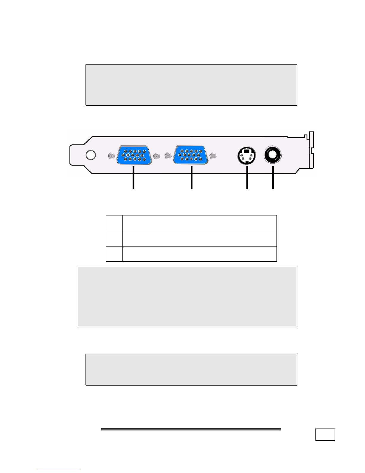
The graphics card shown here is symbolic.
Your graphics card possibly has more or less
jacks. For detailed information refer to the
online help „Information about your PC“.
If your graphics card has a TV output, you can transfer the
image from your PC to the television set.
(Diagram the same)
VGA connectors
S-video Output
Composite Video Output (Cinch)
In order to connect your TV to the PC you will
need an S-Video cable or a composite video cable.
This cable is not included with your computer but
may be obtained from an audio/video specialist or
dealer. Read the operating instructions for your
television set to find out which cable you need.
HOW TO CONNECT THE PC TO A TELEVISION:
To use the TV function you must first connect
the TV to the graphics card before starting up
the PC.
1. Shut down Windows
and power off the PC.
➋
➊ ➊
Page 60
O
O
PPEERRAATTIIOON
N
54
2. If your TV set has a composite video port, connect the
composite video input on your set with the composite
video output on the PC. If your TV set has an S-video
port, connect the S-video input on your set with the
S-video output on the PC.
Switch on the television to see the PC image on your TV set.
3. Start up the PC and wait for Windows to fully load.
4. In the Display Properties program set up the configuration.
5. End configuration by clicking on OK.
SYSTEM REQUIREMENTS
If you wish to use the graphics card in another PC, that PC
must meet the following requirements. Also, updated drivers
for your video card can be download from the Web at
www.medion.com.
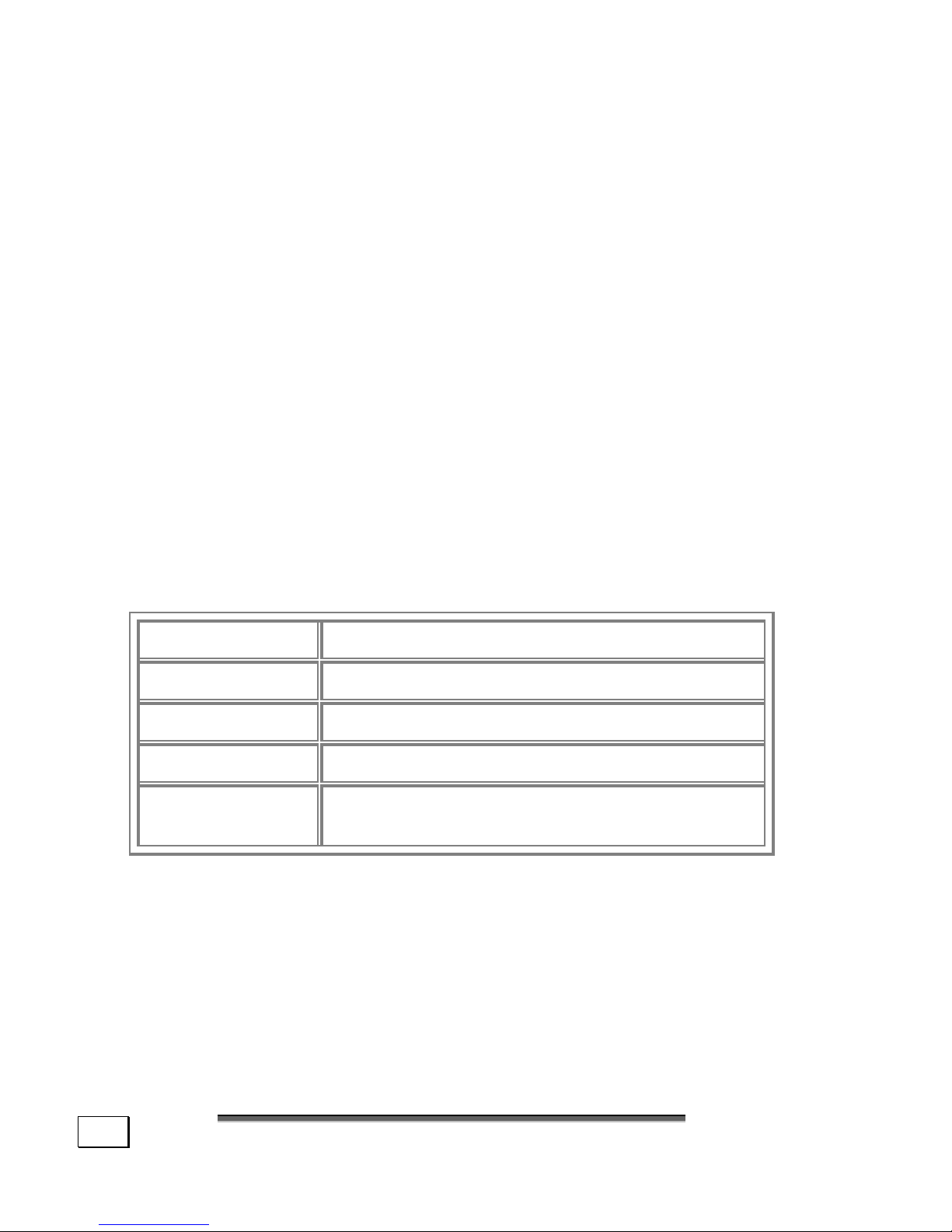
Processor
From Pentium
®
II/III Processor or equivalent
Slot AGP – slot
Monitor VGA, supporting at least 640 x 480 resolution
CD-ROM Min. 2-speed (for driver installation)
Operating system starting from Microsoft Windows®9X/NT 4.0
SP5 and later
Page 61

T
T
HHEE
R
R
AADDIIO
O
--//TTVV-
-
T
T
UUNNEERR
C
C
AARRD
D
55
THE RADIO-/TV- TUNER CARD
The Radio-/TV- Tuner Card is an optional feature. Possibly
your PC is equipped with a so-called Combo board. You recognize this at the modem or ISDN jack on the outside in addition
to the TV/Radio antenna sockets. Then both devices are located on one Combo board requiring a special Combo slot.
In regard to a Combo board the following must be observed:
• The installation, removal and conversion of a board
requires the necessary technical training. Please
read the chapter „Safety precautions“, starting
on p. 1 and p. 83 or consult a PC technician.
• If you would like to use a different modem or
ISDN board, the built-in modem/TV Tuner Combo
board must not be removed or plugged into a
different slot.
• The built-in modem/TV Tuner Combo board only
works properly in the intended blue Combo slot
.
ATTENTION: In another slot the PC may not
be able to start.
SOFTWARE FOR YOUR RADIO/TV TUNER CARD
The Software to watch TV and listen to Radio broadcasts is already
installed and can be found in All Programs, Power Cinema. Get
additional help by pressing the F1 Key. Please keep in mind that
recording broadcasts can occupy up to 2,4 GB per hour.
THE SOUND CARD
Your PC has an integrated stereo sound card (on-board) with
16-bit and 3D spatial sound effects (3D). The sound card is
compatible with the industry standard Sound Blaster and
Microsoft Sound System Version 2.0. This guarantees
optimal support for all popular programs and games.
Page 62
O
O
PPEERRAATTIIOON
N
56
Note: The speaker/headphones output is designed for
active speaker systems or headphones. Passive speakers cannot be used or if they are the quality will be
significantly reduced.
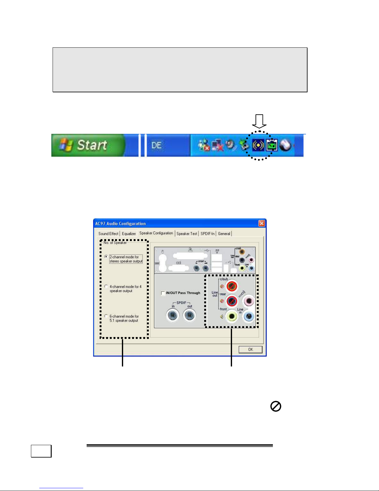
If your PC is equipped with a surround sound you can set it
with the enclosed software as required.
1. Double click this icon:
The Audio Configuration Utility will be launched. To set-up
your sound system according to your speakers click on
“Speaker Configuration” (see next page).
AUDIO CONFIGURATION
Number of speakers Sound routing
According to your selection the outputs are activated or
muted. A muted output is shown with this Symbol:
Page 63

UUSSB
B
P
P
OORRT
T
57
THE MIDI/GAME PORT
At the rear of your Computer you will find the MIDI-/Game
port-Interface. Here you can connect control equipment like
a joystick, gamepad or steering wheel. In general these controllers are used in games or simulations to gain realistic and
easy control of the program. Steering Wheels can add a realistic feeling to racing games.
MIDI is a standard that enables exchange of data between keyboards and similar equipment for musicians. Data is sent to the
respective equipment via DIN cable. The common environment
of a MIDI-implication is:
• Keyboard plays passages or single notes in a sequencer
program.
• The sequence is edited in the PC and stored as a MIDIFile.
• The PC controls the MIDI-equipment (sound creation of
keyboard, Sampler, etc.).
To be able to work with MIDI you will need an adapter cable
that is connected to the MIDI/Game port.
This adapter can be purchased in music specialty shops.
USB PORT
• Devices connected directly to the USB bus should
not draw more than 500 mA. The voltage output is
protected by a fuse (Limited Power Source according
to EN 60950). Should the devices need more
power than this, it will be necessary to provide a
hub (distributor / booster).
On the USB (drawing reference: E) it is possible to connect up
to 127 devices which correspond to the USB standard (1.1
and 2.0 supported). The data transfer speed for USB 1.1 is
1.5 Mbit or 12 Mbit, depending on the device connected.
USB 2.0 can reach up to 480 Mbit.
Page 64

O
O
PPEERRAATTIIOON
N
58
IEEE 1394 (FIRE WIRE)
The IEEE 1394 connector, also known as iLink® or Fire Wire,
is a serial bus standard used for rapid digital data exchange.
APPLICATION OPTIONS FOR IEEE1394
• Connection of digital devices of the entertainment
industry, such as set-top speakers, digital video
and camcorder, ‘Digital Video Disk’ (DVD), television etc.
• Multimedia applications and video processing.
• Input and output devices such as printers, scan-
ners, etc.
TECHNICAL SPECIFICATIONS
• Depending on the application, the maximum data
transfer is about 100, 200 or 400 Mbit/s, corresponding to a data throughput of up to 50 MB per
second.
• The device can be plugged in or unplugged during
operation (hot plugging).
• The standardized cord (‘Shielded Twisted Pair’ STP) includes 6 strands. Two lines are live (8V up
to 40V, 1.5 A max.) and can be used as an external power supply. The four signal lines transfer
data or control information. Some devices do not
require a power supply via the cord so that four
pole plugs are used.
• The voltage output of the 6-pole IEEE 1394 jack is
protected by a fuse (limited power source according to EN60950).
Page 65

T
T
HHEE
N
N
EETTWWOORRK
K
59
THE NETWORK
If your PC is provided with a Fast Ethernet-Network connector, you can connect it to a network. The following explanation refers to PCs with a network connector. You will find further information about networking in the Help section within
the Start menu.
WHAT IS A NETWORK?
A network means connecting your PC to another or several
other PCs. Users can transfer information and data between
computers and share resources such as printers, modems
and hard disk drives.
Here are some practical examples:
• You can exchange Email and manage appointments in an
office.
• Users share a printer in a network and save their data on
a central server.
• Share one modem or one ISDN card among computers
for Internet access.
• Two or more PCs can be connected to play network
games or share data.
Page 66

O
O
PPEERRAATTIIOON
N
60
WHAT DO YOU NEED FOR NETWORKING?
Some requirements have to be fulfilled if you want to make
PCs communicate with one another.
1. The PCs must have the same network cards that support
the same network technology. Unless otherwise stated
your PC will support the current standard, Fast Ethernet
(10/100 Mbit).
2. The network cards must be connected to one another. All
you need is a Shielded Twisted Pair cable (CAT5) which
has an RJ-45 connector.
- If you want to connect two PCs you need a CrossLink cable.
- If more PCs must be connected you need a supplementary distributor (Hub or Switch) and a Patch
cable.
3. All connected PCs need a networking operating system.
That’s the case with Windows
®
.
4. All network PCs must speak the same “language” to understand one another. For this purpose they use protocols.
- The network protocol is determined by the integration of the client server. Loading all PCs with the
same client, for example „Client for Microsoft
®
Networks“, meets the first prerequisite. Your PC, if
equipped with a network connection, has been preconfigured with this server in the factory.
- A transport protocol is required so data can be transported via the network. Your network PC has TCP/IP
preconfigured. It is the most common protocol and
mandatory for internet access. You need IPX/SPX
usually only, if access is required to Novell
®
net-
works.
Page 67
T
T
HHEE
N
N
EETTWWOORRK
K
61
5. The setting of protocols, therefore, must be correct. In
your network computer, TCP/IP is preconfigured so that
the required settings are automatically taken from a socalled DHCP server.
Since usually only large networks are equipped with it,
Windows
®
ME and Windows® XP offer a mechanism
automating this function and accepting this setting
automatically.
You can call these settings in the input request with
ipconfig /all.
6. The correct protocols must be enabled to make shared
access possible. This requires the installation of the
server „File and printer release for Microsoft
®
net-
works “. It is also factory installed.
The release is awarded on the PC where the resource
(folders or printers) are located.
Here the release name or, if necessary, a required password can be determined.
A successful release is indicated by a
stretched out hand below the icon:
7. The released resources can be shown and linked via the
network environment.
Page 68

O
O
PPEERRAATTIIOON
N
62
TROUBLESHOOTING WITHIN THE NETWORK
Why does the network environment not show the releases?
The network environment is delayed in time. Check
the release by searching for the respective com-
puter name.
Why does an error message appear when I click on the
network environment?
The computer name must be unique on the network and may not be the same as the task group.
It appears that the network boards are unable to communicate. What might be the problem?
Maybe one of the used network boards works with a
different speed (e. g. 10 instead 100 Mbit) and
your network computer is unable to recognize this.
If necessary, set the network driver to the compatible speed.
If two PCs should be linked you require a cross-
link cable, otherwise use a patch cable.
In addition, check the protocols and the configu-
ration.
The data transmission is incorrect or very slow. What
might be the problem?
Maybe you have the wrong cable (UTP / CAT3 or
lower) or the problem is the proximity of a power
cord or another source of interference.
For further hints on troubleshooting refer to the Windows
help under „Network errors “.
Page 69

M
M
OODDEEMM
/
/
IISSDDNN
63
MODEM / ISDN
This chapter is intended for systems equipped with a modem
or ISDN jack.
WHAT IS A MODEM?
The term „modem“ is an abbreviation of Modulator/ DEModula-
tor. A modem changes the bit stream of the PC into analog signals which then can also be transmitted via the telephone line
(modulation). The modem on the other side reverses the conversion (demodulation). Simplified, a modem converts outgoing
data into tone and tone incoming via the telephone line back
into data.
The built-in modem is able to receive data according to the ITU
standard for V.90 transmissions with up 56 Kbit/s.
Since the power output of modems is restricted due to the
regulations of some telecommunication providers, the possible
maximum download speed can be restricted. The actual speed
may be dependent on the online conditions and other factors.
Data sent from the user to the server are transmitted with 31.2
Kbit/s. Prerequisite for this high speed reception is an analog
telephone line compatible with the V.90 standard and a corresponding compatible Internet provider or company-owned host
computer.
Contrary to the modem, ISDN data are transmitted digitally.
The modem is fitted with an RJ-11 interface, into which a
standard telephone lead can be plugged. If your modem is a
combo card please make sure that it is used only with the
appropriate port.
WARNING! Use only analog telephone sock-
ets. The modem cannot withstand the voltage
levels of digital telephone systems such PABX
or lines such as ISDN or Broadband services
Page 70

O
O
PPEERRAATTIIOON
N
64
SOFTWARE
This section deals with software, differentiating between
BIOS, application programs and operating systems.
GETTING TO KNOW WINDOWS XP
Windows XP offers different options to understand its operation. We will mention only a few of those options here:
WINDOWS XP HOME EDITION – FIRST STEP
This manual will provide general information about the operating system. We recommend that all beginning users or users
of previous versions of Windows read this information.
WINDOWS
XP
HELP AND SUPPORT
An answer to almost every question can be found in this program. You’ll find it in the Start menu or you can launch it by
simply pressing the F1 key.
MICROSOFT INTERACTIVE TRAINING – STEP BY STEP
Training is the best way to get skills which helps you to perform a specific task save and effectively.
You’ll find it in “All Programs”, “Accessories”. It is also
linked up in “Information about your PC”.
This is a very good feature.
Page 71
S
S
OOFFTTWWAARRE
E
65
WRITING CDS
We describe the writing process with the software Nero –
Burning ROM. Please follow this instruction only if you use
this software.
Note: A writing process should always take
place on its own. Please terminate all running
programs (fax reception, screen savers,
Power-Management etc.).
STARTING UP NERO - BURNING ROM
1. Click on and select .
2. Choose the folder “ahead Nero” and click on “nero -
BURNING ROM“.
3. An assistant appears to help you write CDs. Follow the
instructions dependent on the CD type.
Note: If the assistant (wizard) of Nero - BURNING
ROM does not appear, you will also get to the dia-
log window via the icon for „New arrange-
ment“ (or the key combination CTRL+N),
where you can start the „Wizard“. Then click on
the button „Wizard“ on the right side.
WRITING A CD WITH THE HELP OF THE ASSISTANT
It is very simple to write a CD by using the assistant in nero
-
BURNING ROM. The assistant provides step by step instruc-
tions in order to write a simple CD with audio or PC data.
If you are not familiar with CD-R technology yet, the help
function (call it up using the F1 function key, or under “Help”
in the program bar), as well as this manual provides you with
important information. In order to be able to help you to
write a CD, we have provided a step by step guide for the
most common formats. All settings can be left as their standard values.
Page 72
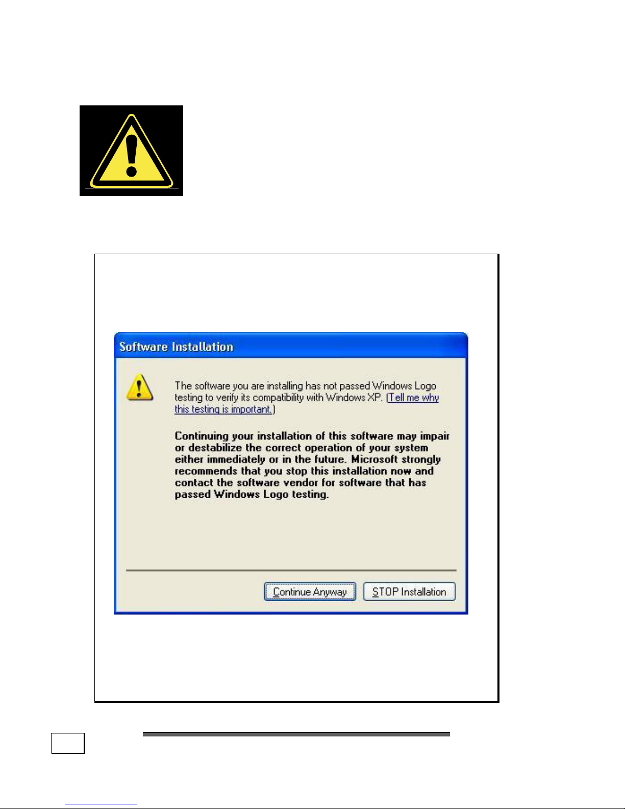
O
O
PPEERRAATTIIOON
N
66
INSTALLATION OF SOFTWARE
It happens that during installation procedure
important files can be changed or even canceled. To avoid eventual problems in using
older files after installation, make sure to
safeguard your hard disk.
The software included in delivery is already pre-installed in
the factory.
Note: If your operating system is configured that the
installation procedure accepts only signed drivers
(default) and software this information screen will
appear:
Although the software lacks the digital signature it
may work properly. Click on “Tell me why this testing
is important” to get detailed information.
Confirm by clicking on “Continue Anyway”.
Page 73
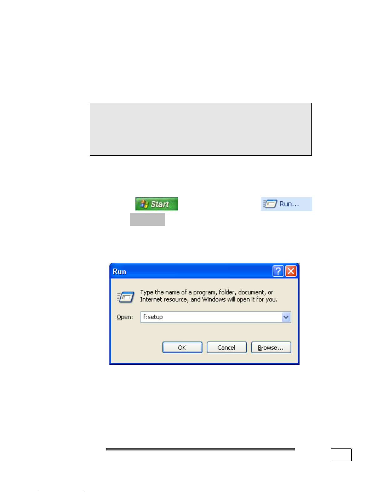
S
S
OOFFTTWWAARRE
E
67
THIS IS HOW TO INSTALL YOUR SOFTWARE:
Please follow the instruction of the software vendor. We will
describe a typical installation. Once you insert a CD, the installation menu is started automatically.
Note: If the automatic start does not work, it
is likely that the so-called Autorun function
has been deactivated. Read the respective
chapter in Windows Help on how to activate
this function.
An example for the manual installation without the autorun
function:
1. Click on
and select the item
(Or hit + R to launch the corresponding dialog).
2. Now enter the letter of the CD-ROM drive followed by
a colon and the program name setup:
3. Click on “OK“.
4. Follow the instruction given by the program.
Page 74
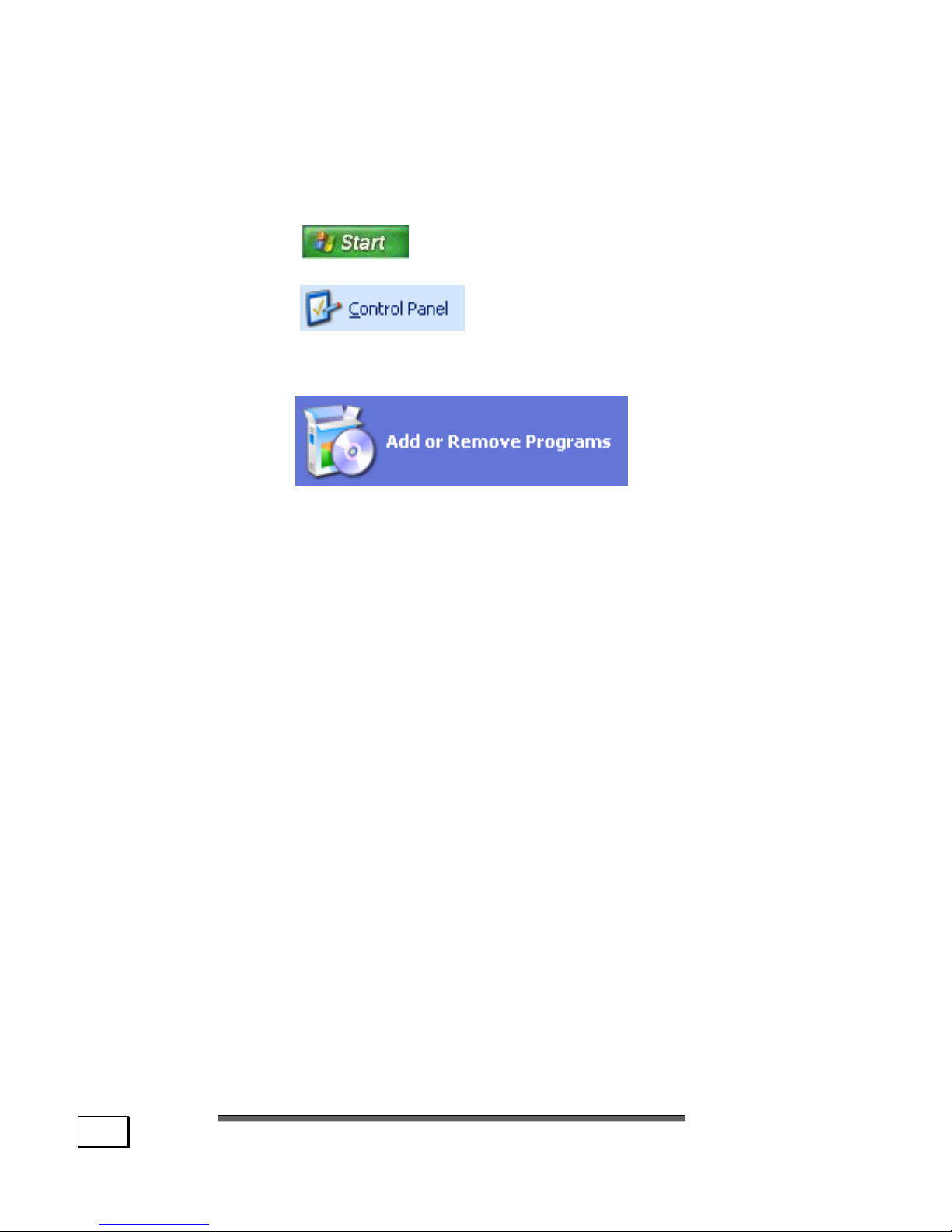
O
O
PPEERRAATTIIOON
N
68
SOFTWARE DEINSTALLATION
In order to remove installed software from your PC, follow
the next steps:
1. Click on
2. Click on
3. Then select the following program:
Select the respective program, start the deinstallation and
follow the instructions on the screen.
If the system becomes unstable due to a certain software or
driver, you are able to recover the stability of the system
with various methods (see starting on page 74).
Then you do not need to uninstall the driver.
Page 75

S
S
OOFFTTWWAARRE
E
69
WINDOWS ACTIVATION
Microsoft is committed to the protection of intellectual property rights and the reduction of software piracy. Therefore
Windows XP contains software-based product activation
technology. Your copy of Windows XP has already been acti-
vated for your PC.
Product activation is needed if some components of your PC
have been replaced or you use a non-authorized BIOS. If
necessary you can activate Windows XP as often as requested.
You will probably need to activate Windows XP by telephone
even if Internet Activation is available. This is due to the preactivated SLP version which runs with a special Product-ID.
However, activation needs your unique Product ID which can
be found on the Certificate of Authenticity sticker on your
PC housing. When you call, please inform your agent that
you are running an OEM-(SLP) version of the software.
PRODUCT ACTIVATION ON YOUR PC
In few cases it may still be required to activate Windows
XP. If an activation via the internet is acknowledged with an
error message you should perform the following steps.
1. Please select the telephone activation and click
until the related screen appears.
2. Now click on Change Product Key. A new win-
dow appears. Enter the product key. This is located on the Certificate of Authenticity (COA),
on the computer’s casing.
3. Acknowledge your entry and follow the instruc-
tions on the screen. Notify your Microsoft consultant, if necessary, that you have an OEM license.
Page 76
O
O
PPEERRAATTIIOON
N
70
BIOS SETUP
THE BIOS SETUP PROGRAM
In the BIOS set up (your PC’s Basic Configuration) you have
a number of parameter settings available for your PC. For
example, you can change the operating mode of the interfaces, security features or power management.
The PC is factory pre-set to guarantee optimum
operation. Please only modify the parameters if
this is absolutely essential and if you are familiar
with the configuration possibilities.
EXECUTION OF THE BIOS SETUP
You can only execute the configuration program when starting the system. If the PC has already been started exit Windows
®
and reboot. Prior to rebooting the PC press the key
»Del« and keep it pressed until the message »Entering
Setup« appears.
Page 77

71
CChhaapptteerr 44
Customer Service & Self-Help
Subject
Page
Self-Help …………………………………………………… 73
Data and System Security ………………………… 73
System Recovery ……………………………………… 74
Restoring the Factory Settings ………………… 75
FAQ –Questions frequently asked …………… 76
Customer Service ……………………………………… 79
Troubleshooting ………………………………………… 79
Driver Support …………………………………………… 81
Additional Support ……………………………………… 81
Cleaning and Care ……………………………………… 82
Recycling and Disposal ……………………………… 82
Upgrades and Repairs ……………………………… 83
Page 78

C
C
UUSSTTOOMMEERR
S
S
EERRVVIICCEE
&
&
S
S
EELLF
F
--H
H
EELLP
P
72
Page 79

D
D
AATTAA AANNDD
S
S
YYSSTTEEMM
S
S
EECCUURRIITTY
Y
73
S
S
EELLF
F
--H
H
EELLP
P
DATA AND SYSTEM SECURITY
The programs described below are part of your Windows operating system. You will additional information on these programs in the Windows Help file.
DATA SECURITY
Back up data regularly on external media such as a CD-R or
CD-RW. Windows offers both a Backup program and a Files
and Settings Transfer Wizard.
You will find both programs in Accessories/System Tools
within the Start menu. Make a backup disk with all your
passwords and the operating system’s original configuration.
MAINTENANCE PROGRAMS
You can avoid some hardware and software errors with the
help programs such as Disk Defragmenter and Disk
Cleanup. The help program System Information can also
be helpful since it gives you detailed information about your
system configuration. You will find these programs in Acces-
sories/System Tools too.
PASSWORD RESET FILE
To protect individual user accounts from complications resulting from lost passwords, users should create a password reset disk and keep it in a safe place. If the user should forget
his/her password, the password can be reset with the password
reset disk so that the user has access again to his/her local user
account.
Windows Help describes how to create a password reset file.
Page 80

C
C
UUSSTTOOMMEERR
S
S
EERRVVIICCEE
&
&
S
S
EELLF
F
--H
H
EELLP
P
74
SYSTEM RECOVERY
Windowsxp provides a useful function enabling the storage of
the so-called Recovery points.
The system remembers the current configuration as a snapshot and returns to this, if necessary. The advantage is that
an unsuccessful installation can be cancelled.
Recovery points are created automatically by the system,
but they can also be set manually.
You can determine and configure yourself the maximum
memory taken up by this. You find this program in the program file under accessories, system programs.
We recommend setting a recovery point before installing a
new software or driver. If the system does not run stable any
longer this enables you usually to return to a workable configuration without deleting newly created documents. In the
next paragraph read your options for a repair of an incorrect
installation.
CORRECTION
Windowsxp includes various functions ensuring that the PC as
well as the installed applications and devices work correctly.
These functions assist you in solving the problems which
might occur by adding, deleting or replacing files required for
the functionality of the operating system, the applications
and devices. The recovery function or functions you use depend on the type of occurring problem or error. For detailed
information refer to the Windows help.
Enter the search word „Overview over the repair“ in order
to evaluate which of the following functions is the safest way
to correct your problem:
Backup, Recovery of the driver, Deactivation of the device,
System recovery, Last function known to work, Secured
mode and system recovery, Recovery console, Windows installation CD.
Please refer to the
tool.
Page 81

R
R
EESSTTOORRIINNGG TTHHEE
F
F
AACCTTOORRYY
S
S
EETTTTIINNGGS
S
75
RESTORING THE FACTORY SETTINGS
Should your system not function correctly, you have the opportunity to recover the original set-up.
LIMITS OF THE RECOVERY
• Changes made to the original configuration (RAS, Desktop or Internet settings) and installed Software will be ignored by this Recovery and will not be reloaded.
• Driver Updates or hardware installed by you will be ignored by this Recovery.
• Beware!
All data on drive C will be erased. If necessary,
backup all required data on drive D.
This recovery will reset your system to its condition at delivery. Printer installations or other additional software must be
reinstalled. You will also need to enter the Product Key (License Number) again.
Attention! If you delete the directory
E:\Recover or the files located there a recov-
ery is no longer possible. For safety reasons
you can copy the file RETTEN.EXE and all
other RETTEN.00X files to a CD-Recordable.
CARRYING OUT A RESTORE
1. First, please read the entire Restore section of the Windows Help file.
2. Insert the Support-CD and reboot the PC.
Attention! Do not use the Product Recovery
CD-ROM for restoration purposes. This disk
does not restore the original set-up. You can
use it when an individual set up is required.
3. Select the option Start from CD-ROM.
4. In the restore menu which now appears, please select 1
and follow the on-screen instructions
5. The PC restarts to its original factory settings.
Page 82

C
C
UUSSTTOOMMEERR
S
S
EERRVVIICCEE
&
&
S
S
EELLF
F
--H
H
EELLP
P
76
FAQ – QUESTIONS FREQUENTLY ASKED
When do I have to activate Windows?
Your software has been preactivated in the factory.
An activation will only be required, if ...
... several components are replaced by others.
... your installed a new motherboard.
... a different BIOS version has been installed.
... you install the software to another computer.
What is the Windows activation?
Your operating instructions include a chapter about
this subject.
How do I perform a data backup?
Use the program Backup for this.
It is important that you follow the operating instructions of this programs.
Make a backup and another backup of selected data
to an external medium (CD-R), to familiarize yourself with the technique.
A backup is unsuitable if you are not able to recover
the data, the medium (CD-R, CD-RW) is defective or
no longer available.
Page 83

FFAAQ
Q
–
–
Q
Q
UUEESSTTIIOONNSS FFRREEQQUUEENNTTLLYY AASSKKEED
D
77
Do I still have to install the enclosed CDs/DVDs?
No. Basically all programs are already preinstalled.
The disks are only intended as backup copies.
When is the recovery of the factory setting recommended?
This method should be chosen as the last resort.
Read chapter „System recovery “ on page 74 concerning the alternatives possible.
Why is the boot partition missing when booting from
the support/ application CD?
The first partition is formatted with the file system
NTFS. Compared to FAT32 this file system offers
more security and a more efficient access. However,
NTFS partitions can only be read from operating systems supporting this. This is not the case in the
aforementioned CD.
Page 84

C
C
UUSSTTOOMMEERR
S
S
EERRVVIICCEE
&
&
S
S
EELLF
F
--H
H
EELLP
P
78
Page 85

T
T
RROOUUBBLLEESSHHOOOOTTIINNG
G
79
C
C
UUSSTTOOMMEERR
S
S
EERRVVIICCE
E
TROUBLESHOOTING
LOCALIZE THE CAUSE
Errors can have simple causes, but sometimes they are
caused by faulty equipment. We would like to give you some
ideas to solve common problems. Should these instructions
not lead to success, please feel free to call us.
Check Cables and Connections
Visibly check all cables and connections. Should all lights be
off, check whether all equipment is supplied with power.
• Check power points, power cable and all power switches.
• Switch off the PC and check all cable connections. Check
the connections to peripherals. Do not exchange cables,
even though they may look similar. The polarity in those
cables may be different. When it is confirmed that the
computer has power and all connections are correct, turn
the computer on again.
THE POWER ON SELF TEST (POST)
The Power On Self Test (POST) is executed during each boot
process to test the memory, Motherboard, display, keyboard
and other components. If the PC does not pass the POST but
beeps several times, or if the screen remains blank, call your
PC support technician.
The PC can only be switched off by pressing
the power switch for 4 seconds.
Frequent use of the programs Disk Defragmenter and Disk
Cleanup will help you to avoid problems with your operating
system.
Page 86

C
C
UUSSTTOOMMEERR
S
S
EERRVVIICCEE
&
&
S
S
EELLF
F
--H
H
EELLP
P
80
ERRORS AND POSSIBLE CAUSES
The monitor is blank:
- Confirm that the system is not in stand-by mode. Press
any key on the keyboard to test this out.
- Check that the cable is fully connected.
Wrong Date and Time:
- Double-click the clock on the taskbar and correct the date
and time.
- Check that Regional Settings are set to English (British/United Kingdom)
No data can be accessed from the CD-ROM Drive:
- Check whether the CD is inserted correctly.
- Is the CD-ROM (Drive E) displayed in Windows Explorer?
If so, test another CD.
The Printer does not work:
- Check the printer cable.
- Do a Printer Self Test.
- Should several pieces of equipment be operating from the
same port, check all peripherals and reinstall the drivers.
- If you have access to the Internet, download and install
the latest drivers from the manufacturer’s Web site.
Page 87

D
D
RRIIVVEERR
S
S
UUPPPPOORRT
T
81
DRIVER SUPPORT
This PC has been extensively tested in our laboratories with a
large number of compatible devices. It fulfils all required standards and complies with the standard “Designed for Windows”,
which certifies utmost compatibility.
However, often the software drivers for individual components
are updated from time to time. This is a regular process provided by the manufactured to mend possible compatibility problems that may occur with components (e.g., programs or hardware) that were not tested at the time of your PC’s manufacture. Driver updates and the latest information on your product
are available on the Internet.
Visit Medion on the Web at
www.medion.com
ADDITIONAL SUPPORT
If the suggestions in the above section have not solved your
problem, please contact the service hotline and we will attempt
to help you solve the problem. Before you contact the Technology Center, however, please have the following information
available:
- How is your computer configured?
- What additional peripherals do you use?
- What messages, if any, appear on your screen?
- What software were you using when the error occurred?
- What steps have you already undertaken to solve the
problem?
- Have you upgraded or removed drivers or hardware?
- Can you manually repeat the problem?
- If you have been given a customer number previously,
please quote this.
Page 88
C
C
UUSSTTOOMMEERR
S
S
EERRVVIICCEE
&
&
S
S
EELLF
F
--H
H
EELLP
P
82
CLEANING AND CARE
The lifetime of the PC can be extended by taking the following measures:
• Before cleaning, always remove the power plug and
all connecting cables.
• Clean the PC with a damp, lint-free cloth.
• Warning! There are no user-serviceable or
user-cleanable parts inside the PC housing.
• DO NOT use any solvents, corrosive or
gaseous cleaning agents.
• DO NOT use CD-ROM cleaning disks or
similar products that clean the lens of the
laser to clean your CD-ROM/CDR-W/DVDdrive.
RECYCLING AND DISPOSAL
This PC and its packaging was produced mostly from materials which can be disposed of in an environmentally friendly
manner and be professionally recycled.
After its use the computer will be taken back and recycled or
use will be made of its useful material, if it is returned in a
condition corresponding to its intended use.
Parts not usable will be properly disposed of.
ATTENTION! There is a lithium battery (Type:
Sony™, CR 2032) on the motherboard. No
type of battery belongs in the household
waste. All are taken back free of charge by the
manufacturer, dealer or their representatives
for a proper method of utilization or disposal.
Should you have any questions concerning the disposal
please contact your dealer or our service.
Page 89

U
U
PPGGRRAADDEESS AANNDD
R
R
EEPPAAIIRRS
S
83
TRANSPORTING THE PC
Please observe the following guidelines when transporting
the PC:
• To avoid damage during transport, store the PC in its
original packaging.
• Wait until the PC has reached ambient (room) temperature
before connecting it to the power supply. Drastic variations
in temperature and humidity can create condensation
within the PC and may cause it to short-circuit.
UPGRADES AND REPAIRS
• Only a qualified engineer should perform upgrades and
repairs to your PC.
• If you do not have the necessary qualifications, go to an
appropriate Service Engineer. Please contact our Ser-
vice Center if you are experiencing technical problems
with your PC.
NOTES FOR SERVICE ENGINEERS
• Before opening the housing, disconnect the PC from
all power sources and remove any connecting cables. If the PC has not been disconnected from the
power outlet before being opened, there is a danger to
life through electric shock. There is also a risk of dam-
age to the components.
•
Internal components of the PC may be damaged by
electrostatic discharge (ESD). Carry out system upgrades and changes in an ESD-protected workshop.
If no such workshop is available, wear an antistatic
wrist strap or touch a highly conductive metal object.
Medion can repair damage sustained by inappropriate
handling for a fee
.
• Use only original spare parts.
Page 90

C
C
UUSSTTOOMMEERR
S
S
EERRVVIICCEE
&
&
S
S
EELLF
F
--H
H
EELLP
P
84
Caution: Lithium batteries can not handle in-
tense pressure, high temperatures or fire.
Danger of explosion if replaced incorrectly.
Replace batteries with a compatible type as
recommended by the manufacturer.
Lithium batteries are hazardous waste and require proper disposal. Contact the Service
Center for additional information on battery
disposal.
Notes on Laser Radiation :
Laser devices of Laser Class 1 to Laser Class 3b may be used
in the PC. Where the PC housing remains closed, the device
meets the requirements of Laser Class 1. By opening the PC
housing you will gain access to laser devices of up to Laser
Class 3b.
The CD-ROM-/CDRW-/DVD-drives installed contain no user-
serviceable parts.
When removing and/or opening laser devices, the following
guidelines must be observed
:
• Only the manufacturer should perform repairs to the
CD-ROM-/CDRW-/DVD-drives.
• DO NOT look into the laser beam, even while wearing
optical protection.
• DO NOT allow yourself to be exposed to the laser
beam. Avoid exposure of the eyes or skin to direct or
stray radiation.
Page 91

85
CChhaapptteerr 55
Appendix
Subject
Page
Standards …………………………………………………… 87
Electromagnetic Compatibility …………………… 87
Electrical Safety ………………………………………… 88
Ergonomics ………………………………………………… 88
Noise Emission …………………………………………… 88
Supplementary Information ……………………… 88
FCC Compliance Statement ……………………… 89
Declaration of Conformity ………………………… 90
Warranty …………………………………………………… 91
Page 92

A
A
PPPPEENNDDIIX
X
86
Page 93

S
S
TTAANNDDAARRDDS
S
87
STANDARDS
This PC meets the requirements of the following standards:
ELECTROMAGNETIC COMPATIBILITY
This PC meets the following requirements for standards of electromagnetic compatibility and electrical safety:
EN 55022
Information technology equipment - Radio disturbance characteristics - Limits and methods of measurement.
EN 55024
Information technology equipment - Immunity characteristics - Limits and methods of measurement.
EN 61000-3-2
Limits - Limits for harmonic current emissions
(equipment input current up to and including 16 A per
phase).
EN 61000-3-3
Limits - Limitation of voltage fluctuations and flicker
in low-voltage supply systems for equipment with a
rated current up to 16 A.
• Keep the PC at least one meter (approximately three feet)
away from high frequency and magnetic interference
sources (e.g., televisions, loudspeaker cabinets, mobile
telephones, etc.) in order to avoid malfunctions and/or
loss of data.
• Please note that only shielded cables shorter than
3 meters (9.84 ft) should be used for the LPT, COM,
USB, IEEE 1394, audio, video and network interfaces
with this PC.
• When connecting additional components, please observe
the Guidelines on Electromagnetic Compatibility (EMC).
Page 94

A
A
PPPPEENNDDIIX
X
88
ELECTRICAL SAFETY
EN 60950
Safety of information technology equipment.
• The connection of devices is limited to equipment that com-
plies with EN60950 “Safety of information technology
equipment” or EN60065 “Audio, video and similar electronic apparatus. Safety requirements”
• For U.S. / Canadian purposes:
The PC should only be connected to equipment which
complies with UL 60950 / CAN CSA 22.2 No 60950
ERGONOMICS
EN 29241-3
Ergonomic requirements for office work with visual display terminals (VDTs). Visual display requirements.
EN ISO 9241-8
Ergonomic requirements for office work with visual display terminals (VDTs). Requirements for
displayed colors.
NOISE EMISSION
ISO 7779
(ISO 9296)
Acoustics. Measurement of airborne noise emitted by
information technology and telecommunications
equipment.
This PC fulfills the requirements of noise emissions according
to ISO 7779 with following values:
Operating Mode Max. Sound power level L
WAd
(B/A)
(declared according to ISO 9296)
Idling 4.8
Operating 5.2
Max. Sound pressure level L
pAm
(dB/A)
(declared according to ISO 9296)
At bystander position Idling 40
St bystander position Operating 47
SUPPLEMENTARY INFORMATION
This product complies with the requirements of the R&TTE
Directive 1999/5/EC and carries the CE-marking accordingly.
CE 0682
Page 95

S
S
TTAANNDDAARRDDS
S
89
FCC COMPLIANCE STATEMENT
This equipment has been tested and found to comply with
the limits for a Class B digital device, pursuant to Part 15 of
FCC Rules. These limits are designed to provide reasonable
protection against harmful interference in a residential installation. This equipment generates, uses, and can radiate radio
frequency energy and, if not installed and used in accordance
with the instructions, may cause harmful interference to radio communications. However, there is no guarantee that
interference will not occur in a particular installation. If this
equipment does cause harmful interference to radio or television reception, which can be determined by turning the
equipment off and on, the user is encouraged to try to correct the interference by one or more of the following measures:
• Reorient or relocate the receiving antenna.
• Increase the separation between the equipment and
receiver.
• Connect the equipment into an outlet on a circuit
different from that to which the receiver is connected.
• Consult the dealer or an experienced technician for
help.
Changes or modifications not expressly approved by the party
responsible for compliance could void the user’s authority to
operate the equipment. Shielded interface cables, if any, must
be used in order to comply with the emission limits.
Page 96

A
A
PPPPEENNDDIIX
X
90
DECLARATION OF CONFORMITY
According to 47CFR, Parts 2 and 15 for
Class B Personal Computers:
We: Medion Aktiengesellschaft____________
(Name of the Responsible Party)
Located at: Gänsemarkt 16 – 18_________________
D-45127 Essen______________________
Germany__________________________
(Adress, City, State, Zip Code)
Fax : 0 201 / 81 081 – 227____
(Facsimile Number for conformity issues only
)
Declare under sole responsibility that the product identified herein, complies
with 47CFR Parts 2 and 15 of the FCC rules as a Class B digital device. Each
product marketed, is identical to the representative unit tested and found to
be compliant with the standards. Records maintained continue to reflect the
equipment being produced can be expected to be within the variation accepted, due to quantity production and testing on a statistical basis as required by 47CFR §2.909. Operation is subject to the following two conditions: (1) This device may not cause harmful interference, and (2) This device must accept any interference received, including interference that may
cause undesired operation. The above named party is responsible for ensuring that the equipment complies with the standards of 47CFR §§15.101 to
15.109.
Trade Name: Medion
Type or
Model Number: PC MT6 MED MT xxx (where xxx = 0-999)
Party Responsible: MEDION AG
Executed on (Date), at (Place): 9
th
of September 2002, Essen
Page 97

W
W
AARRRRAANNTTY
Y
91
WARRANTY
PLEASE READ THIS LIMITED WARRANTY CAREFULLY TO UNDERSTAND YOUR
RIGHTS AND OBLIGATIONS.
The receipt is considered valid proof of purchase and should be kept in a
safe place. This receipt will be required for receiving any warranty service.
This warranty is transferable. When transferring ownership to a third party,
please provide the receipt and warranty information.
We warrant to the end user that each product, including related software,
accessories, media and supplies, shall be free from defects in materials and
workmanship for the warranty time from date of purchase. This warranty
covers only those defects that arise as a result of normal use of the product.
This warranty does not cover any other problems, including problems that
arise as a result of improper maintenance or modification; software, accessories, media or supplies not provided or supported by us; or operation
outside the manufacturer’s specifications.
Any parts in this PC repaired or exchanged by a valid service representative
will be covered under the original warranty period. Back up all programs and
data before shipping this PC for repair under the warranty agreement. Do
not leave any media in the disk drives. Products shipped without accessories
will be returned without accessories. Any replacement product or component
may be either new or like new, provided that it’s functionality is at least
equal to that of the product being replaced.
LIMITATION OF WARRANTY
To the extent allowed by local law, no other warranties or are made with
respect to this personal computer or the warranty services by any person,
including but not limited to us and our suppliers. The express warranty
stated above is the only express warranty made to you and is provided in
lieu of all other express or implied warranties and conditions (if any) including any created by any other documentation or packaging. For additional
warranty information, please refer to enclosed warranty card.
LIMITS OF LIABILITY
To the extent allowed by local law, except for the obligations specifically set
forth in this warranty statement, in no event shall we or our third party
suppliers are liable for direct, indirect, special, incidental, or consequential
damage, whether based on contract or any other legal theory and whether
advised of the possibility of such damages. This includes loss or damage of
personal data on your PC.
Page 98

A
A
PPPPEENNDDIIX
X
92
LOCAL LAW
This warranty statement gives you legal rights. You may also have other
rights which vary from jurisdiction to jurisdiction. To the extent this warranty
statement is inconsistent with local law, certain disclaimers and limitations of
this statement may not apply to the customer.
MAKING COPIES OF THIS MANUAL
This manual contains information protected by law. All rights reserved. Duplicating this information in mechanical, electronic, or any other form, without the
written approval by the manufacturer, is prohibited by copyright law.
Page 99

I
I
NNDDEEX
X
93
INDEX
A-B
Ambient Temperature ............ 13
Arrow keys ........................... 35
Audience ................................ ii
Audio CDs............................. 47
Audio configuration.................56
Autorun................................ 67
BIOS Setup........................... 70
Boot-CD .......................... 47, 48
Buffer Underrun .................... 48
C
Card Reader.......................... 41
Care .................................... 82
CD-blanks ............................ 46
CD-Extra .............................. 48
CD-R.................................... 48
CD-Rom-/DVD-Drive
as bootdrive ...................... 43
CD-RW ................................. 48
CF ....................................... 41
Cleaning ............................... 82
Cleaning agents .................... 82
Colors of the CD blanks .......... 46
Compact Flash ...................... 41
Connecting ........................... 15
Recording ......................... 22
Video inlet......................... 22
Customer Service .................. 79
D
DAO..................................... 48
Data and System Security ...... 73
Data security ........................ 73
Data Security .......................... 4
Data-CD ............................... 47
Declaration of Conformity ....... 90
Directories ............................ 40
Disk at once.......................... 48
DVD Technology .................... 43
E-F
Electrical Safety .....................88
Electromagnetic Compatibility..87
EMC .....................................87
Ergonomics ...........................88
Execution of the Bios Setup .....70
Extended play CDs ................. 51
FAQ...................................... 76
FCC Compliance Statement .....89
Finalising ..............................49
Fixing ...................................49
Front connectors .................... 14
G-H
Game Port.............................57
Gamepad ..............................57
Graphics Card ........................52
Hard Drive ............................39
HFS ......................................49
Hotline..................................81
Hybrid-CD ............................. 49
I-L
IBM® Microdrive .....................41
Image...................................49
ISO 9660 ........................ 47, 49
Joliet .............................. 47, 49
Joystick ................................57
Laser Radiation ......................84
Lead-In / -Out ....................... 49
M
Main Power Switch..................24
Maintenance ..........................82
Maintenance programs............73
Memory ................................52
Memory Stick ........................41
MIDI.....................................57
Mixed Mode ..................... 48, 49
MMC .....................................41
MP3......................................50
MultiMediaCard ......................41
Multi-Read.............................50
Page 100

A
A
PPPPEENNDDIIX
X
94
Multi-Session ........................ 50
INDEX (CONTINUED)
N-O
Nero .................................... 65
Network
Troubleshooting ................. 62
What do you need for
networking?................... 60
What is a Network? ............ 59
Noise Emission ...................... 88
On the fly ............................. 50
Operational Safety
Connecting........................ 15
P-Q
Packet Writing....................... 50
Password reset File ................ 73
Playstation ........................... 50
POST ................................... 79
Power On Self Test ................ 79
PSX-CD ........................... 48, 50
Quality ................................... ii
Questions frequently asked..... 76
QWERTY keyboard................. 31
R
Relection layer ...................... 46
Restore ................................ 75
Restoring Factory Settings ...... 75
S
Safety Instructions ...................1
SD .......................................41
Sector ..................................51
Secure Digital ........................ 41
Serial Number .........................ii
Service Engineers .................. 83
Session................................. 51
SmartMedia........................... 41
Software Deinstallation ........... 68
Sound Card ........................... 55
Standards
Electrical Safety ................. 88
Electromagnetic
Compatibility .................. 87
Ergonomics........................ 88
FCC Compliance Statement.. 89
Noise Emission ................... 88
Synthetic layer ......................46
System Recovery ................... 74
T
Table of contents ...................51
TAO...................................... 51
TOC...................................... 51
Track.................................... 51
Track at once ........................51
Transporting..........................83
Troubleshooting ............... 74, 79
Types of CDs ......................... 47
U-Z
UDF................................ 48, 51
Unicode ................................51
Universal Disk Format.............51
USB Port ............................... 57
Video-CD ..............................47
Warranty ..............................91
Wheel................................... 57
Windows
®
Desktop .................26
Writing CDs ...........................65
 Loading...