

Page 1

English
Page 2

Page 3

Table of Contents
This operator’s manual supports you during the installation and operation of the plasma display. Detailed
descriptions and drawings as well as the user-friendly user guidance per on-screen display facilitate installation
and operation even for inexperienced users. The contents of this manual can change without prior notification
on account of further technical developments. Ensure that you always utilise the newest version of this operator’s
manual.
Chapter Description Pages
Standards . . . . . . . . . . . . . . . . . . . . . . . . . . . . . . . . . . . . . . . . . . . . . . . . . . . . . . . . . . . . . . . 5
Important Notes On Safety . . . . . . . . . . . . . . . . . . . . . . . . . . . . . . . . . . . . . . . . . . . . . . . . . 6
1 Product Introduction . . . . . . . . . . . . . . . . . . . . . . . . . . . . . . . . . . . . . . . . . . . . . . . . . . . . . 8
2 Installation And Start-up . . . . . . . . . . . . . . . . . . . . . . . . . . . . . . . . . . . . . . . . . . . . . . . . 10
2.1 Checking The Scope Of Delivery . . . . . . . . . . . . . . . . . . . . . . . . . . . . . . . . . . . . . . . . . . . . . . 10
2.2 Packing/Unpacking . . . . . . . . . . . . . . . . . . . . . . . . . . . . . . . . . . . . . . . . . . . . . . . . . . . . . . . . 10
2.3 For Your Information And Safety . . . . . . . . . . . . . . . . . . . . . . . . . . . . . . . . . . . . . . . . . . . . . 11
2.4 Reference For Wall Mounting . . . . . . . . . . . . . . . . . . . . . . . . . . . . . . . . . . . . . . . . . . . . . . . . 12
2.5 Reference For Table Mounting . . . . . . . . . . . . . . . . . . . . . . . . . . . . . . . . . . . . . . . . . . . . . . . 13
2.6 Installation Of Connecting Line . . . . . . . . . . . . . . . . . . . . . . . . . . . . . . . . . . . . . . . . . . . . . . 15
2.7 Start-up . . . . . . . . . . . . . . . . . . . . . . . . . . . . . . . . . . . . . . . . . . . . . . . . . . . . . . . . . . . . . . . . . . 15
2.7.1 Connection Of Signal Sources . . . . . . . . . . . . . . . . . . . . . . . . . . . . . . . . . . . . . . . . . . . . . . . . 15
2.7.2 Connection Of Sound . . . . . . . . . . . . . . . . . . . . . . . . . . . . . . . . . . . . . . . . . . . . . . . . . . . . . . 15
2.7.3 Remote Control . . . . . . . . . . . . . . . . . . . . . . . . . . . . . . . . . . . . . . . . . . . . . . . . . . . . . . . . . . . . 16
2.7.4 Connection Of Mains Cable . . . . . . . . . . . . . . . . . . . . . . . . . . . . . . . . . . . . . . . . . . . . . . . . . 17
2.7.5 Turning On The Plasma Display . . . . . . . . . . . . . . . . . . . . . . . . . . . . . . . . . . . . . . . . . . . . . . . 18
3 Interconnection Options . . . . . . . . . . . . . . . . . . . . . . . . . . . . . . . . . . . . . . . . . . . . . . . . . . . 18
3.1 Appliance Coupler Summary . . . . . . . . . . . . . . . . . . . . . . . . . . . . . . . . . . . . . . . . . . . . . . . . 18
3.2 Connection To Compatible PCs . . . . . . . . . . . . . . . . . . . . . . . . . . . . . . . . . . . . . . . . . . . . . . . 19
3.3 Operating Modes . . . . . . . . . . . . . . . . . . . . . . . . . . . . . . . . . . . . . . . . . . . . . . . . . . . . . . . . . . 21
4 Remote Control . . . . . . . . . . . . . . . . . . . . . . . . . . . . . . . . . . . . . . . . . . . . . . . . . . . . . . . . . . . 22
4.1 Direct Functions . . . . . . . . . . . . . . . . . . . . . . . . . . . . . . . . . . . . . . . . . . . . . . . . . . . . . . . . . . 22
4.2 Everyday Settings . . . . . . . . . . . . . . . . . . . . . . . . . . . . . . . . . . . . . . . . . . . . . . . . . . . . . . . . . 25
4.2.1 On-Screen Display (OSD) . . . . . . . . . . . . . . . . . . . . . . . . . . . . . . . . . . . . . . . . . . . . . . . . . . . . 25
5.0 Format Adjustments . . . . . . . . . . . . . . . . . . . . . . . . . . . . . . . . . . . . . . . . . . . . . . . . . . . . . . . 39
5.1 Video Signal Source . . . . . . . . . . . . . . . . . . . . . . . . . . . . . . . . . . . . . . . . . . . . . . . . . . . . . . . . 39
6 Error Analysis And Possible Recovery . . . . . . . . . . . . . . . . . . . . . . . . . . . . . . . . . . . . . . . 40
6.1 Repairs . . . . . . . . . . . . . . . . . . . . . . . . . . . . . . . . . . . . . . . . . . . . . . . . . . . . . . . . . . . . . . . . . . 41
6.2 Cleaning The Display And Housing . . . . . . . . . . . . . . . . . . . . . . . . . . . . . . . . . . . . . . . . . . . 42
6.3 Declaration Of Return . . . . . . . . . . . . . . . . . . . . . . . . . . . . . . . . . . . . . . . . . . . . . . . . . . . . . . 42
7 Technical Specifications . . . . . . . . . . . . . . . . . . . . . . . . . . . . . . . . . . . . . . . . . . . . . . . . . . . 43
7.1 Product Attributes . . . . . . . . . . . . . . . . . . . . . . . . . . . . . . . . . . . . . . . . . . . . . . . . . . . . . . . . 43
7.2 Display . . . . . . . . . . . . . . . . . . . . . . . . . . . . . . . . . . . . . . . . . . . . . . . . . . . . . . . . . . . . . . . . . 44
7.3 Resolution . . . . . . . . . . . . . . . . . . . . . . . . . . . . . . . . . . . . . . . . . . . . . . . . . . . . . . . . . . . . . . . 44
Page 4

Chapter Description Pages
7.4 Colour Display . . . . . . . . . . . . . . . . . . . . . . . . . . . . . . . . . . . . . . . . . . . . . . . . . . . . . . . . . . . 44
7.5 Operation . . . . . . . . . . . . . . . . . . . . . . . . . . . . . . . . . . . . . . . . . . . . . . . . . . . . . . . . . . . . . . . 44
7.6 PC Frequency Range . . . . . . . . . . . . . . . . . . . . . . . . . . . . . . . . . . . . . . . . . . . . . . . . . . . . . . . 44
7.7 Video/Synchronisation . . . . . . . . . . . . . . . . . . . . . . . . . . . . . . . . . . . . . . . . . . . . . . . . . . . . . . 44
7.8 Video/Standards . . . . . . . . . . . . . . . . . . . . . . . . . . . . . . . . . . . . . . . . . . . . . . . . . . . . . . . . . . . 44
7.9 Video/PC Inputs . . . . . . . . . . . . . . . . . . . . . . . . . . . . . . . . . . . . . . . . . . . . . . . . . . . . . . . . . . . 44
7.10 Audio . . . . . . . . . . . . . . . . . . . . . . . . . . . . . . . . . . . . . . . . . . . . . . . . . . . . . . . . . . . . . . . . . . . . 44
7.11 Operating Conditions . . . . . . . . . . . . . . . . . . . . . . . . . . . . . . . . . . . . . . . . . . . . . . . . . . . . . . . 44
7.12 Conformities . . . . . . . . . . . . . . . . . . . . . . . . . . . . . . . . . . . . . . . . . . . . . . . . . . . . . . . . . . . . . 45
7.13 Dimensions & Weight . . . . . . . . . . . . . . . . . . . . . . . . . . . . . . . . . . . . . . . . . . . . . . . . . . . . . . 45
7.14 IR Remote Control . . . . . . . . . . . . . . . . . . . . . . . . . . . . . . . . . . . . . . . . . . . . . . . . . . . . . . . . . 45
7.15 Loudspeaker (optionally) . . . . . . . . . . . . . . . . . . . . . . . . . . . . . . . . . . . . . . . . . . . . . . . . . . . . 45
Important: The supplier constantly strives to improve the quality of product documentation. As our
customer, you can contribute to this. We ask that you inform us about vague descriptions,
drawings or ambiguous terms. We look forward to your suggestions, which improve the
utilisation of this operator’s manual.
Page 5

Standards
The plasma display at hand is an information
technology device.
The plasma display complies with the following
guidelines and standards:
• 89/336/CEE from 3 May 1989 with subsequent
modifications (Directive 92/31/CEE from April
1992 and Directive 93/68/CEE from 22 July 1993)
• 73/23/CEE from 19 February 1973 with subsequent
modifications (Directive 93/68/CEE from 22 July
1993)
• EN55022, EN55024, EN61000-2-2/-3
(Electromagnetic Compatibility)
• EN60950 (Safety Requirements)
The conformity with the requirements is characterised
by the CE symbol attached to the product.
5
REFERENCE:
This is a Class A device. This device can cause radio
!
WARNING
disturbances in the living area; in this case the operator
can be required to implement appropriate measures.
Suitable measures could be:
• In the event of disturbances, connect the device
with a different socket
• Align the antenna of a disturbed radio receiver
differently
• Increase the distance between the disturbed device
and this product
The manufacturer cannot be held liable for operation
beyond the operating conditions as described in the
manual. In addition, your product liability and
warranty claims expire as a result of such action.
Page 6

6
Important notes on safety!
Read and heed the notes on safety so that no hazard to your health arises during contractual use. Errors during
installation and connection can damage the device or subsequently related devices.
Always keep the operating instructions within reach. Heed the warnings on the device and in the operating
instructions.
• General reference
Before you connect the plasma display, please
carefully read through the general notes on safety
and the operating instructions. Only in this manner
can you utilise all functions safely and reliably.
As far as possible, keep the operating instructions
together with the device so that you can use it to
look up information.
Heed the warnings on the device and in the
operating instructions.
Never allow children to utilise electrical devices
without supervision.
• Environmental conditions
Never operate the plasma display under
environmental conditions which differ from those
of the technical data. Divergent conditions can
lead to endangerment, fire or breakdown of the
device.
Protect the plasma display against moisture. This
pertains to permanent high humidity, the proximity
to water, water drops and water splashes as well
as rain. Do not place any water-filled containers
(e.g. vases) on the device.
Protect the device against heat. Avoid the proximity
to fire, heating devices, ovens or permanent
exposure to direct sunlight.
Protect the display against heat accumulation. Do
not cover the ventilation slots. Maintain a distance
of at least 10 cm above and below the ventilation
slots as well as laterally to furniture and to the
ceiling. Do not furnish the device with curtains.
The display is designed for mounting in vertical
position on walls or installations.
upper middle. For safe disconnection of the display
from the mains voltage, the mains switch is to be
turned off and the mains cable is to be removed
from the mains input module.
Connect the plasma display only to a socket with
earthing contacts installed according to regulations,
and whose main voltage conforms with the device’s
technical data. See to it that the mains plug and
the socket are accessible at all times. Install the
mains cable in such a fashion that nobody can
get caught in it. Use only the supplied mains cable.
Protect it against damages, and do not make any
alterations to it. Never use a damaged mains cable.
• Signal inputs
Always turn the plasma display and the signal
source off before you establish a connection
between both devices.
• Disturbances
In the event of damages to the mains cable or the
device, immediately pull the mains plug from the
socket.
Under no circumstances should you attempt to
open and/or to repair the device yourself. Instead,
contact our Service Hotline or another suitable
professional workshop.
• Batteries
Batteries can be life-threatening when swallowed.
That’s why you should safeguard batteries from
the reach of small children. Immediate medical
assistance should be utilised if a battery has been
swallowed.
Always take the exhausted batteries out of the
remote control immediately, since these leak and
can cause damage as a result.
The enclosed batteries may not be charged or
reactivated by other means, not taken apart,
thrown in fire or short-circuited.
• Mains connection
The mains input and the mains switch are located
on the rear side. The mains input is located on the
upper right and the mains switch is placed in the
Page 7

Important notes on safety!
Exhausted batteries do not belong in household
waste. The batteries must be disposed of at the
collection points provided for this purpose.
• Cleaning and maintenance
Before cleaning, turn the device off, and pull the
mains plug from the socket. Wait a few minutes
so that the capacitors in the device can be
completely discharged.
Use only a slightly dampened, soft cloth for
cleaning. You should avoid chemical solvents and
cleaning agents, because these can damage the
surfaces.
• The plasma display generates high voltage internally
for the gas discharge. Turn the device off and pull
the mains plug from the socket during installation,
maintenance and repairs. Wait a few minutes so
that the capacitors in the device can be completely
discharged.
• In case foreign elements such as water, liquids,
metal parts, etc. get into the plasma display, pull
the mains plug out immediately. Never attempt
to touch anything inside the device with any kind
of objects. The danger of an electric shock or
accident exists.
• Pull out the mains plug immediately if smoke,
unpleasant odour or unusual noises are emitted
from the device. Also proceed in the same manner
if the display is no longer able to present an image
after being turned on or during operation. Never
attempt to continue operating the display in this
condition.
• The plasma display has a glass surface. Should the
device be subjected to excessive loading (e.g.
through shock, vibration, bending and heat shock),
the glass surface can break. Do not subject the
glass surface to any pressure or shock. Should the
glass be broken, immediately pull the mains plug
and do not touch the broken glass with bare hands.
• When the plasma display has been switched to
the stand-by mode it is still connected to the
mains. You must switch the mains switch into the
0 position or pull the mains plug from the socket
for complete disconnection.
• For ergonomic reasons it is recommended to avoid
using red and blue fonts or symbols on dark
backgrounds. Such a display causes poor readability
due to the lower contrast, and prematurely fatigues
the eyes. Therefore, please use high-contrast
displays as much as possible, e.g. black font on a
white background.
• During the connection of external loudspeakers,
pay attention to the loudspeaker output technical
data. In the event of insufficient dimensioning of
the loudspeaker, the loudspeaker and/or the builtin amplifier can be damaged.
• Packaging and packing resources which are no
longer needed are able to be recycled, and should
always be turned in for recycling.
7
• In the event of lengthy absence or during
thunderstorms, pull the mains plug from the socket,
and pull the house antenna socket from the
antenna jack.
• Never plug-in or pull-out the mains plug with wet
hands. Never operate the mains switch with wet
hands.
• Utilise only the supplied mains cable. Protect it
against damages, and do not make any alterations
to it. Never use a damaged mains cable.
Page 8

1 Product Introduction
8
State of the art signal processing, a flat 16:9 plasma
display with 106 cm screen diagonal, and an attractive
housing which features lesser modular depth in
combination with a user-friendly, interactive remote
control present a new generation of information
presentation.
The utilisation of the newest plasma display generation
guarantees high-contrast, brilliant video images as
well as computer displays and presentations. A variety
of interconnection options facilitate integration into
existing and new systems of visualisation.
• Display: flat - large - slim
The new plasma display offers 852 x 480 pixel
resolution on a screen surface of 920mm x 512mm.
16.77 million colours with 256 RGB gradations (8
bit resolution) offer unlimited colour display and
true-to-detail image playback. Enjoy video and
data images on a 106 cm screen diagonal, and be
impressed by the slight depth of only 129 mm.
• Quiet
A new type of cooling system enables the operation
of the plasma display without disturbing fan noises.
Quiet like a conventional television, the plasma
display provides the new standard for the living
room and for the conference room.
A remaining audio noise level of approx. 25 dB A
in consequence of plasma technology corresponds
to the current state of the art.
• Everything in one housing
Display, power supply and image & sound signal
processing are accommodated in one housing. This
facilitates mounting on the wall. Hanging on a
wall like a painting, all signal inputs and outputs
are easily accessible. Bothe of the loudspeaker
jacks offer well-balanced listening pleasure in
connection with external loudspeakers.
• User interface
IR remote control and On-Screen-Display (OSD)
make operation a matter of child’s play. The OSD
offers clearly structured menus for the selection
of signal sources, image and sound.
• Digital signal processing
The plasma display is equipped with the latest
standard of digital signal processing in 8-bit
technology. It offers – to name just a few things
– characteristics such as efficient algorithms in
order to present 4:3 video and data images in high
quality while filling the screen on a 16:9 display.
• Images: High-contrast and distortion-free under
all circumstances
In order to maintain the high contrast ratio and
the outstanding readability even under critical
lighting conditions, the new front glass pane is
provided with fine etching on the front side.
• Installation: Simple and fast
Various attachment devices are provided to you
for installation — no matter whether the display
is attached to the wall, or even installed on the
floor or a table.
• Advantages of digital technique
Digital graphics cards offer superior imaging
performances. With the digital DVI connection the
plasma display offers convincing performances,
and remains downwardly compatible to existing
analogue graphics cards.
• Digital noise suppression
You can activate motion-adaptive noise suppression
per OSD, and align the quality of the image material
accordingaly. The automatic reduction of noise
suppression ensures artefact-free reproduction of
rapidly moving image components.
• Video / Computer VGA / Audio
The broad connection capability provides the
PAL/NTSC/SECAM video standards (CSCC,RGB and
SVHS), multistandard TV tuner (which offers up
to 99 TV channels with automatic and manual
programming), VGA/SVGA, and even includes a
16:9 VGA format with 848 x 480 pixel resolution.
• Exact and constant colour rendition
The superior, finely-nuanced colour rendition is
supplemented by the possibility of gamma
adjustment. You can make the optimal gamma,
colour temperature, contrast and brightness
adjustment for every input per OSD.
Page 9

PC FORMATS DOS Modes 640 x 400 and 720 x 400
VGA (640 x 480) @ 50Hz – 85Hz repetition rate
SVGA (800 x 600) @ 50Hz – 85Hz repetition rate
WVGA (848 x 480) @ 50Hz – 85Hz repetition rate
XGA (1024 x 768) @ 50Hz – 85Hz repetition rate
IMAGE FORMATS 4:3, 16:9, zoom, user zoom, screen-filling, automatic non-linear
INPUTS/VIDEO Mini DIN . . . . . . . Y/C / Hi 8 (PAL, SECAM, NTSC)
Cinch . . . . . . . . . . CVBS Video In (PAL, SECAM, NTSC)
SCART 1 . . . . . . . Y/C, CVBS, RGB (PAL, SECAM, NTSC),
CVBS output
SCART 2 . . . . . . . Y/C, CVBS (PAL, SECAM, NTSC),
CVBS output
RF Tuner . . . . . . . VHF/UHF/HYPERBAND for terrestrial
antennas or cable networks (47MHz to 861MHz)
(PAL/SECAM)
PC DVI (I) . . . . . . . . . VGA/SVGA/WVGA/XGA
Analogue and digital (DVI)
AUDIO INPUTS Y/C (S-Video)
CVBS
SCART 1
SCART 2
PC
OUTPUTS Audio Line Out . . adjustable
loudspeaker . . . . 2 x 7W sine @ 4Ω
CONTROL On-Screen Display Menu . . . . 4 languages (D, E, F, I)
IR remote control CMM3
VIDEOTEXT TOP FLOF . . . . . . . 256 pages of memory
control with special keys on the remote control
VOLTAGE 220V – 240V AC alternating voltage
50Hz/60Hz
9
CURRENT 1,8A
Page 10
2 Installation and Start-up
2.1 Checking the Scope of Delivery
10
Your plasma display has been tested with great care
and packed before delivery. It is available for use
immediately after unpacking. After unpacking the
display, please check for possible transport damages
and completeness of delivery. In the event of transport
damages, the supplier can only allow your claims if
you inform them about this before the initial start-
Scope of delivery:
1. Plasma Display
2. Loudspeaker (optionally)
3. Wall mounting device
4. Table base
5. Mounting material (4 x screws M8, 1 x Allen wrench size 5)
6. Remote control
7. 2 x LR03 batteries
8. Mains cable 2.5 m
9. HD-Sub on DVI-I video cable 2.0 m
10. Operator’s manual
11. Warranty card
12. Drilling template
up. If a part of the scope of delivery is missing, please
contact the Service Hotline. The missing component
will be sent to you immediately without charge. Please
always keep this operator’s manual in the vicinity of
the installation site so that it is available at your side
for support at all times.
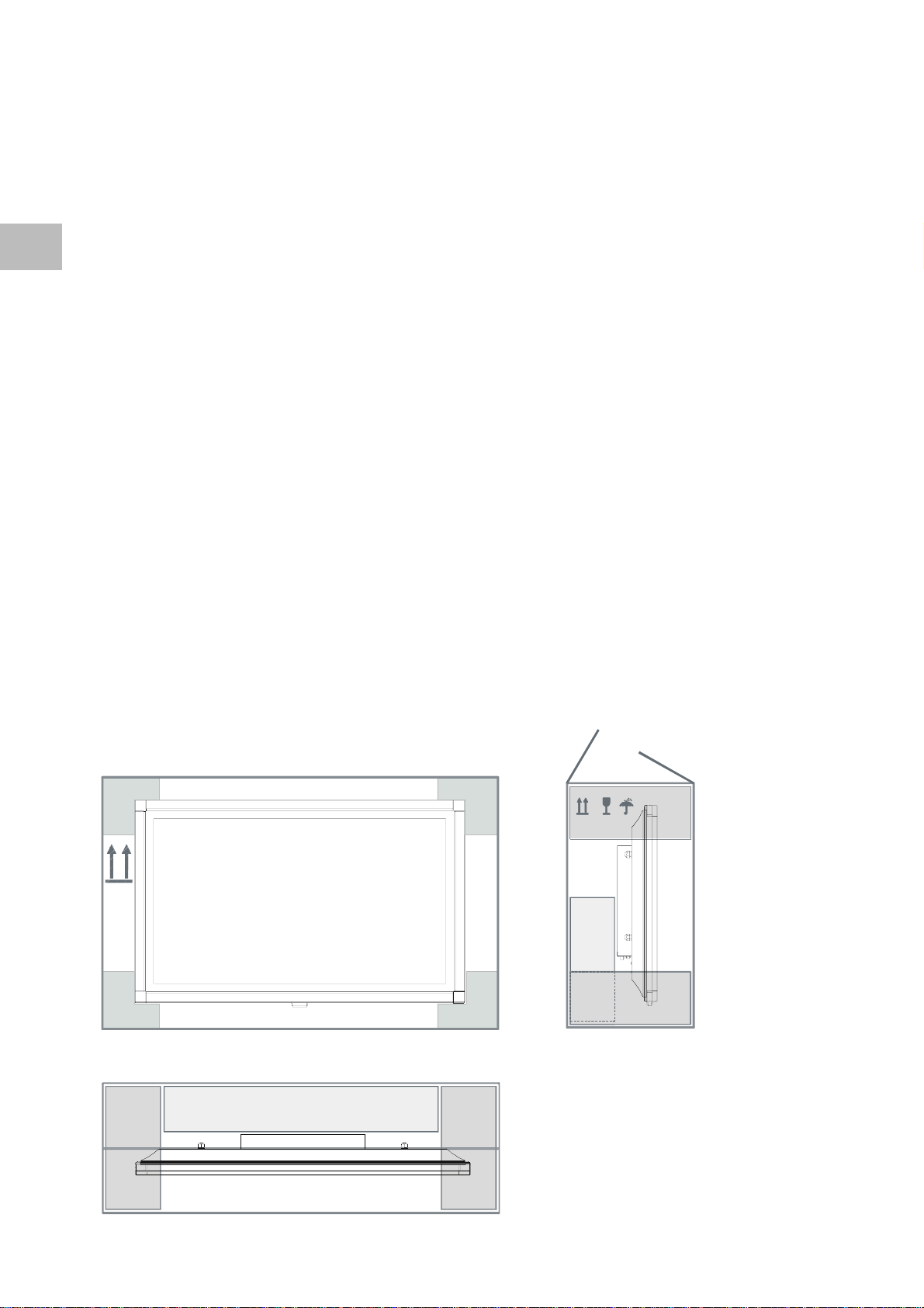
2.2 Packing/Unpacking
Packing dimensions H x W x D: approx. 760 x 1160 x 370 mm
TOP
PLASMA DISPLAY
REAR
ACCESSORIES
TOP
OPENING EDGE
FRONT
Page 11

• Place the carton upright with the underside on
firm ground. You will recognise the top side by
the direction of the arrowheads on the longitudinal
side.
• Open the packaging tape on the opening edge,
and fold back both lids outwardly.
• Remove both of the packing elements which are
lying on the top, as well as the packing element
which is located on the back side of the device.
• Now remove the carton, along with the accessory
parts which are located on the back side, from
the packaging.
• Remove the wall bracket from the back side of
the device. For this purpose, please slightly tilt
the display forward at first, and pull out the
Styrofoam block which is situated between the
back side of the device and the wall bracket. After
that you can pull out (upwardly) the wall bracket
from the packaging.
2.3 For Your Information and Safety
• Depending on your choice, you can either mount
the wall bracket on the mounting site, or place
the standing pedestal on a secure base surface.
• After mounting the wall bracket or the table base,
remove the protective foil on the upper side of
the display so that you can remove the display
from the packaging.
• Always remove the display from the packaging
only with two people. Trying to remove the display
by yourself is hazardous to your health.
• Hang the removed display either in the wall
mounting bracket unit or place the display on the
standing base.
• Please pay attention that you do not place the
display on its underside, because the infrared
sensor is located there.
11
2.3.1 Installation references
Select the installation site according to the following criteria:
1. Line of vision
Despite its very large line of vision, the plasma display provides the best performance in a directly vertical line
of vision. Align the display along the axis of the most frequently utilised line of vision.
2. Installation site
A suitable installation site should comply with the following criteria:
• Light reflections Avoid installation opposite windows or other light sources.
• Access to mains input The mains input and mains switch should be easily accessible at all times.
• Ventilation Maintain a distance of at least 10 cm above and beneath the ventilation
slots to furnishings or to the ceiling.
• Ambient temperature It must lie between 5° and 35°C for safe and reliable operation.
Page 12
12
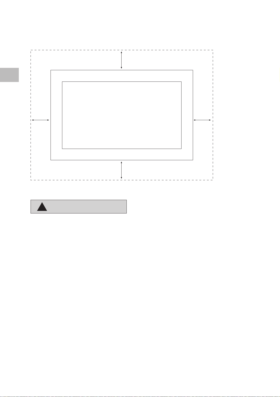
2.4 Reference (instructions) for Wall Mounting
10cm
Clearance zone
10cm
Clearance
zone
!
CAUTION
10cm
Clearance
zone
10cm
Clearance zone
• The plasma display may only be mounted on
vertical (plumb) walls by means of the wall
mounting unit.
• Before beginning the mounting, make sure that
the display is turned off and the mains cable and
signal cable are unplugged.
• The background has to be firm and structurally
able to carry a load.
• Appropriate materials are to be utilised for varying
wall superstructures, such as wooden walls or
hollow-space walls. If there’s any doubt, contact
your responsible sales or service department.
The wall mounting unit is located on the back side of the device. It consists of two vertical brackets which are
connected with cross studs. In the packaging you will find a template which will facilitate the mounting on
the wall.
The wall mounting unit functions as a type of interface between the display and the wall. The concept consists
of attaching the mounting unit to the wall with the help of the template in the first phase, and thereafter
hanging the display in the mounting unit.
The manufacturer recommends using M8 dowels.
Page 13
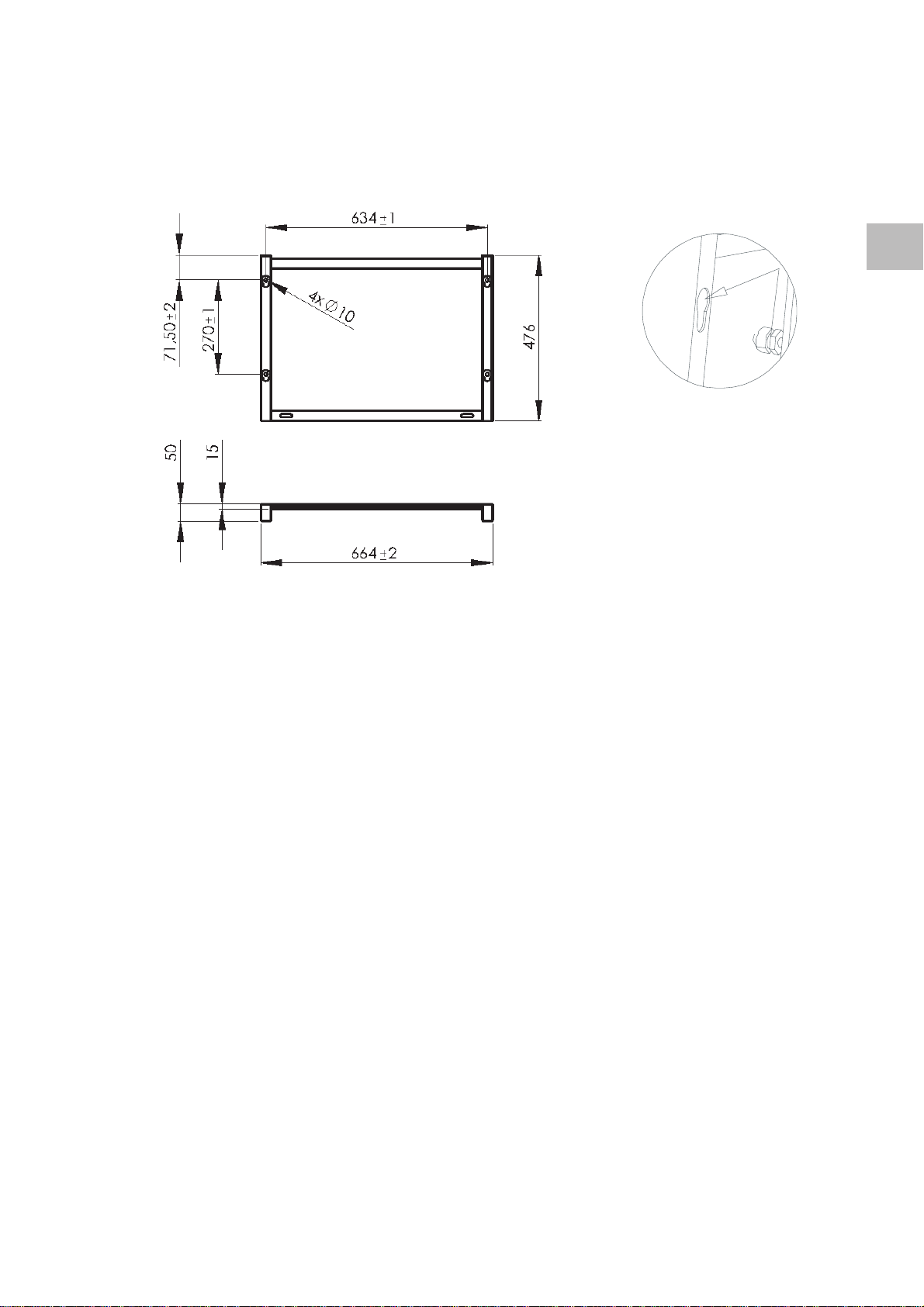
• The attachment points are situated horizontally at a spacing of 634 mm and vertically at a spacing of
270 mm. The spacing between the upper edge and the upper attachment point amounts to 71.5 mm, including
the plastic covering.
• The centre of each of the attachment points is shifted 15 mm inwards in reference to the vertical edge of
the wall mounting unit.
• The holes for the screws have a diameter of 10 mm.
• Please see to it that the display is about 19 mm lower than the attachment points on the wall after being
mounted.
• Mount the display with the pins on the back side in the larger openings of the wall mounting unit, and
slowly lower it into the U-shaped cut-out.
13
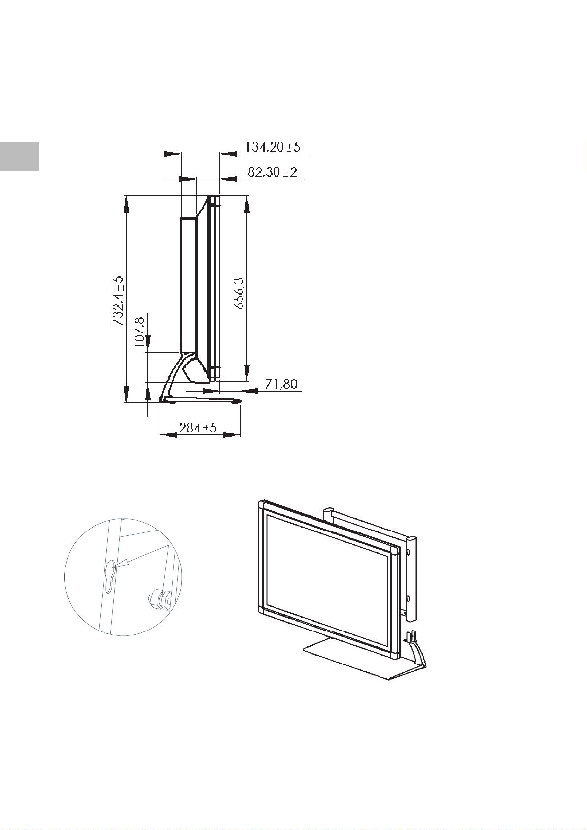
2.5 Reference (instructions) for Table Mounting
The table base consists of the wall mounting unit, table base plate and two connecting pieces left and right.
• Fasten the two connecting pieces with one Allen
screw each according to the enclosed assembly
drawing.
• Put both connecting pieces from bottom up in the
wall mounting unit and fix these with one Allen
screw each. Tighten all screws well.
• Place the table base on a stable and horizontal
base surface.
• Mount the display with all four mounting pins at
the rear side of the display into the openings of
the wall mounting unit and lower it slowly.
Page 14
14
B (1: 2,5)
Page 15

2.6 Installation of Connecting Line
The following is to be heeded during the connection
and installation of the mains cable and the video
cable (e.g. SCART, Y/C . . .):
• Please lead the connecting lines to the rear.
Please pay attention that the signal lines are not
placed directly along the display surface.
• In the interest of good image quality, utilise only
shielded, high-quality signal cable. A high-quality
75 Ω coaxial cable should be utilised for connecting
the video signal. Poor quality signal cable can
2.7 Start-up
There are a few tasks to take care of before you turn
on your plasma display for the first time.
• Turn your plasma display off during all tasks
for start-up, and pull the mains plug from
the socket.
1. Connection of signal sources: TV, VIDEO, PC
2. Connection of sound playback
3. Install the batteries in the remote control
4. Connect the mains cable
5. Turn on the plasma display
2.7.1 Connection of Signal Sources
Connect the cables of your signal sources at the input
panel of the plasma display.
You need an antenna cable for the built-in TV tuner,
and a suitable cinch cable for external audio signal
sources.
Cables for connecting PC signal sources are provided.
result in strong disturbances and formation of
shadows in the displayed image, as well as
exceeding the permissible EMC level. The
mechanical interlocks of the individual plug-andsocket connectors are necessary for perfect and
safe operation of the device.
• You should also avoid placing signal sources such
as a PC or a video recorder in front of the display.
Please place these signal sources on the side or
behind of the display.
• Always turn the device off before connecting
a signal source to your plasma display.
2.7.2 Connection of Sound (playback)
Your plasma display has various audio outputs located
on the input panel for sound playback. The connection
of your hi-fi or Dolby Surround system is also possible,
as well as the connection of external loudspeakers to
your built-in amplifier.
• Turn your plasma display off before you
connect external loudspeakers. Note the
technical data of the loudspeaker output,
and pay attention to sufficient dimensioning
of the loudspeaker.
• Always turn the device off before you
establish a connection between your hi-fi
or Dolby Surround system and your plasma
display.
15
Page 16

2.7.3 Remote Control
16
All of your plasma display’s selection and adjustment
possibilities are able to be carried out with the remote
control. Menus on the display are available for your
support. You will find the description of the menus
starting on page 25 in this manual.
• Remote control range
The remote control only functions properly when
there is no obstruction between the operation and
the infrared sensor on the front side of the plasma
display.
It can happen that the display is not able to receive
the remote control signals or their function range is
severely inhibited, although there is no obstruction
in the way. The reason for this is the infrared radiation
which the display itself emits. Come closer to the
display with the remote control.
The remote control range is reduced when the batteries
become weaker. In this case, please replace the
batteries.
• Installing the batteries
Please push aside the battery compartment cover
with a downward motion. The cover unlocks and
is able to be removed.
Insert the enclosed batteries. While doing so, pay
attention to the proper polarity of the batteries.
This is indicated in the battery compartment.
In order to close the battery compartment, put
the cover back on again, and carefully press it
shut. Your remote control is now ready for
operation.
-
+
IR Remote Sensor
!
CAUTION
30°
+
i
Reference for disposal of batteries:
Exhausted batteries do not belong in household waste.
They must be deposited at a collection site for old
batteries (e.g. battery collection box at dealer) or
turned in with hazardous waste.
-
Page 17

2.7.4 Connection of Mains Cable
Always utilise the enclosed mains cable in order to
guarantee optimal image quality.
First of all, insert the mains cable into the input panel,
and only thereafter into the socket.
• Never utilise a damaged mains cable!
• Use only sockets with a protective earthing
conductor system to ensure safe operation.
A line filter and switches for stabilisation of the supply
voltages ensure safe operation within normal mains
voltage variations. In case the mains voltage lies
beyond the stated limits, please contact your
responsible sales office. In the event the mains cable
cannot be utilised on account of differing standards
in your country, please see to it that you utilise a
mains cable commensurate with the country-specific
standards which are listed in the following:
• USA UL
• Germany VDE
• Canada CSA
• Switzerland SEV
• Great Britain BASEC/BS
• Japan MITI
This list is not complete. For reasons of safety it may
be necessary to select a different safety standard.
At any rate, the mains cable has to consist of three
wire conductors of at least 10A/0.75 mm
avoid an accident as a result of electric shock. One
of the three wires is implemented on both ends of
the cable as an earthing contact connection.
2
in order to
17
Input panel
Mains input
Socket
Input panel (below)
Operational display / Infrared sensor
On Off
Mains switch
Page 18

2.7.5 Turning On
the Plasma Display
18
You can only control your plasma display with the
remote control when the device is in stand-by mode.
Switch the mains switch in the input panel into
position I . The operational display on the front side
of the display screen lights up red.
• The plasma display is always connected to the
power supply network in stand-by mode. You must
switch the mains switch into position 0 and pull
the mains plug from the socket for complete
disconnection.
• The display has a mains adapter, and can be
operated with a supply voltage of 220V - 240V
AC and 50Hz/60Hz ±10%.
3 Interconnection Options
3.1 Appliance Coupler Summary
On the plasma display’s input panel you will find
interconnection options for: • Terrestrial antenna
• cable network
• Video recorder
• Satellite tuner
• Video-CD player
• DVD player
• Video camera
• Personal computer
Please note that for safe operation only devices can be connected to the interfaces which comply with the
corresponding safety requirements.
The plasma display’s input panel provides various
connections as a link to video sources (PAL, SECAM
and NTSC) such as video cameras, DVD players and
video recorders.
• The Y/C input (S-Video) provides the analogue
luminance and colour signals on separate lines.
It is frequently utilised as a link to video cameras
and DVD players.
• The CVBS video input provides the luminance
and colour signals on one line. It provides a cinch
plug-and-socket connector which is a very
reasonable and simple link, and is frequently
utilised as a link to video recorders.
Page 19

• The SCART 1 video input provides the connection
to CVBS, Y/C (S-Video) and RGB video inputs, a
CVBS output for connecting a video recorder, and
audio inputs & outputs.
• The SCART 2 video input provides CVBS, Y/C (SVideo) video inputs, a CVBS output for connecting
a video recorder, and audio inputs & outputs.
• The RF tuner input with IEC jack links the display
for connection of terrestrial antennas or cable
channel systems.
3.2 Connection to Compatible PC’s
• The combined input DVI-I (analogue and digital)
serves for the connection of high-resolution graphic
card signals.
• The RS232 control input for connecting a PC
facilitates diagnosis in the event of servicing.
• The OSD input menu enables you to select the
desired video input.
• The “ADJUSTMENT” menu enables you to set the
configuration of inputs so that, for example, the
same input is presented after turning on the display.
19
The plasma display is suitable for utilisation together
with compatible computers. Your PC has one of the
following configurations:
• A built-in graphics adapter.
• An installed graphics card.
Both variations have one analogue and one digital
video output jack for connection of a monitor. If you
are not sure about which jack the monitor is to be
connected to, you can read more about this in either
the graphics card or computer user manuals. In case
of doubt, ask for details at your service department.
Please use only the enclosed signal cable for
connection.
Page 20

20
For the connection of your monitor to the system,
proceed as follows:
1. Turn off the power supply to the computer and
the display.
2. In case it is necessary, install a graphics card
according to the directions in the graphics card
user manual. Make sure that the graphics card
utilised generates a video format that lies within
the limits which are stated in the specifications
(VGA, XGA).
3. Connect the signal cable to the display’s signal
input (DVI-I), and to your computer’s corresponding
video jack (15-pin mini D-DUB) or DVI.
Attention: Falsely connected signal cables can
lead to irregularities in monitor
operation, a poor image quality or
damage to the display, and shorten
service life as a result.
4. Connect the supplied mains cable on one side
with the display, and on the other side with a
grounded wall socket.
5. Turn on the display and the computer, and select
an appropriate input (PC/RGB or PC/DVI).
6. During the first utilisation of an analogue video
format (RGB). The plasma display always
automatically executes the auto-adjust function.
During this period the display image “shuttles
about” in order to attain the optimal position and
playback.
7. You can store frequently used formats as user
formats. The display recognises these formats, and
immediately presents them in correct fashion
without execution of the auto-adjust function.
8. Finish the adjustment of your display by actuating
the following listed OSD function, which is found
in the “INPUTS ADJUSTMENT” menu: “USER
FORMATS”.
9. The DDC compatibility ensures that the utilised
graphics card only generates video formats within
the limits stated in the specifications.
10. Many graphics cards offer formats with 848 x 480
screen resolution in 16:9 format. The utilisation
of this resolution is recommended for optimal
display presentation.
Reference:
With some inconvenient PC formats, the H/V position
and image size have to possibly be manually adjusted
for ending the alignment with the geometric
adjustments in this menu. The “AUTO-ADJUST” function
is extremely dependent on the image presentation.
The presentation of a white frame or a grid cross is
well-suited. Should problems arise during connection
of the display, please read Chapter 6: “Maintenance
(Maintenance and Repairs), use the description of the
individual OSD functions, or contact your service site.
Page 21

3.3 Operating Modes
PC mode
For optimal image reproduction, we recommend the
848 x 480, 640 x 480 or 720 x 400 pixel resolutions.
The 848 x 480 pixel resolution corresponds to the
display matrix, and offers the best image reproduction.
You can obtain the driver for this resolution on the
Internet pages of most of the well-known
manufacturers of graphics cards.
In contrast to applications with CRT monitors, with
flat displays it is not necessary to select a high image
refresh for a flicker-free presentation. A refresh of
60Hz is recommended.
Video recorder mode
The utilisation of Y/C (S-Video) or SCART 2 inputs (see
fig. page 18) is recommended for enhancement of
image quality - if your recorder offers playback in Y/C
(S-Video) format.
DVD player mode
The application of the RGB operating mode, which
can be connected to the SCART 1 input, is
recommended for optimal utilisation. In case your
player does not offer this operating mode, please use
the Y/C (S-Video) signal mode (see fig. page 18).
21
Operating mode at the beginning of utilisation
The operating mode of the technology applied
recommends the viewing of predominately motion
images or at least the constant alternation of still
frame images for the first 100 hours.
Image sticking
The manufacturer would like to point out to you that
during lengthy viewing of freeze pictures (e.g. PC
playback), the image is still slightly visible in the full
mask for a few minutes during the subsequent playback
of a different source. This is known as “image sticking”.
This “vanishing” residual image is caused by the system,
and does not represent a flaw. Therefore it cannot be
considered as a case for warranty claim.
Video cable
A high-quality 75 Ω coaxial cable should be utilised for
the connection of the video signal. Poor quality signal
cable can result in strong disturbances and formation
of shadows in the displayed image, as well as exceeding
the permissible EMC level. The mechanical interlocks of
the individual plug-and-socket connectors are necessary
for perfect and safe operation of the device.
!
CAUTION
Page 22

22
4 Remote control
4.1 Direct Functions
• The remote control only functions if the
plasma display has been turned on with the
mains switch beforehand.
STDBY
TV
VIDEO
PC
FREEZE
After you have turned on the display once with the
mains switch, you can turn it on and off with the
remote control (stand-by). Press the keys TV, VIDEO,
PC, or 1,2, ... in order to turn on the display. Press the
stand-by button in order to switch the display into
stand-by mode.
CAUTION: If the display has been turned on in standby mode, it is still linked with the mains. For complete
disconnection you must first switch the mains switch
into the “off” (0) position, and then pull the mains
cable.
You can switch directly to TV mode with this key.
You can switch directly to VIDEO mode
(SCART1 -> SCART2 -> CVBS -> Y/C) with this key.
You can switch directly to PC mode
(PC RGB -> PC DVI) with this key.
With this key you can “freeze” the actual image.
The freeze picture remains on the screen until you
push this key again.
TEXT
Mute
M/S
MENU
P / P_
VOL + / VOL –
This key serves for switching into the teletext operating
mode.
This key turns the sound off until you press the key
again or change the volume.
With this key you can switch between playback in
stereo, “Stereo Enlarged”, mono, or “pseudo stereo”;
or, respectively, you can switch between Channel A
or B in two-language sound.
OSD user guide recall and abort
This function enables the selection of television
channels in ascending or descending order.
You can increase and decrease the volume of the
audio playback with this key.
Page 23

/
This function enables the selection and aborting of
the submenu.
23
1 ... 9 and 0
F
- /--
PIP
L/?
AUTO
Direct statement of programme slot, teletext page
selection.
With this key you can switch between the one-digit
programme numbers (1...9) and the two-digit numbers
(11...99).
With this key you can recall the Picture-in-Picture
(PIP) function, which allows the simultaneous
presentation of video signals on the PC signal. The
PIP is always blended into the lower right corner. You
can change the size and the position in the OSD.
With this key you can jump directly into the TV
operating mode in the “PROGRAMME LIST” menu.
With this key you can jump directly into the “AUTO
PROGRAMMING” mode (TV operating mode).
With this key you can switch back and forth between
the different image formats (1:1 -> Fit to Screen ->
User Zoom) or (4:3 -> 16:9 -> User Zoom).
I
Pressing this key shows information on the current
programme and on the signal source. You can switch
through the individual submenus by pressing this key
on the basic setting.
Red, green,
blue key
M / RED
With this key you can fade in and fade out the
time.
Teletext
The respective function is determined by the actual
teletext page and described there.
If the TV channel offers TOP teletext information, you
will recognise this in the multicoloured info line at
the bottom.
The red M (Memo) key directly stores executed
parameter changes. Another storage option is the
aborting of a menu function or the OSD.
The red key is utilised in the teletext and auto-tuning
mode.
In the teletext mode the function assignment is
effected through a fade-in in the lower display area.
In most cases the red key is assigned for the selection
function.
Page 24

24
In the auto-tuning operating mode the function
assignment is effected by the fade-in of a red field.
GREEN
RED
BLUE
FREEZE
PAGE
In the teletext mode the green key is utilised for
downward movement.
In the teletext mode the red key is utilised for upward
movement.
In the teletext mode the blue key is utilised for the
activation of a selected function or page.
The blue key guides you in the TOP teletext menu.
You will be guided through the offered text pages
with the colour keys.
Page change stopping/starting. Some teletext pages
consist of several sub-pages, which are automatically
broadcast in succession. With this key you can hold
the page being shown at the moment on the display.
In the upper left corner of the display HOLD will be
shown.
Enlarge page. Press this key several times. At first, the
upper, and then the lower and then the complete
teletext page will be shown.
?
There are hidden messages on some teletext pages.
Press this key to view the messages.
F 1
F 2
F 3
F 4
Directly selecting the page
Enter the desired number of the page with the
numerical keys. As long as the number is incomplete,
the display “P 2 – –” appears in the upper left corner
of the display screen.
Configuration-contingent assignment, unused.
Configuration-contingent assignment, unused.
Configuration-contingent assignment, unused.
Configuration-contingent assignment, unused.
Page 25

4.2 Everyday Settings
4.2.1 On-Screen Display (OSD)
There are six keys on the remote control for menu
control. These keys have the following functions:
1. Press the MENU key and the main menu appears
on the upper left hand edge of the screen. The
main menu “INPUTS” is illustrated in colour, and
is ready for the selection of an input with the
key. Press the key in order to activate the
selected submenu or the selected function. The
selected menu is blended in and provides you with
further functions.
2. Press the key in order to exit the selected
submenu or the selected function.
3. Press the key or keys in order to make a
selection in the main menu or in submenus. The
selected menu or the selected function is illustrated
in colour during the selection.
25
4. Press the key to activate a function. In many
cases, the selected function will be displayed as
a bar graph and figures. The key reduces the
value of a selected function, and the key increases
the value. The implemented values are executed
immediately.
5. The M key or exiting the OSD stores the changes
made.
6. You can exit the OSD by pressing the “MENU” key.
In this case the OSD will fade out immediately.
Page 26

26
Main Menu
Inputs >
Picture >
Display >
Sound >
Setting >
Info >
SETTINGS Submenu
Inputs > Select: PC (RGB)
Picture > Settings >
Display >
Ton >
Setting >
Info >
• The submenu “Settings” is dependent on the selected signal source.
• PC (RGB)
• PC (DVI)
• CVBS
• SCART 2 (without RGB)
• SCART 1 (with RGB)
• TV tuner (terrestrial)
• Y/C (S-Video)
SETTINGS Submenu
PC (RGB) H freq.: 38 kHz
V freq.: 60 Hz
Pixel Clk: 43.53 MHz
H / V pole: + / -
User timings >
Auto Setup > Auto Mode Set Up of geometry parameter
V pos.:
V size:
H size:
H pos.:
Phase:
• The plasma display always executes the auto-adjust function automatically during the initial utilisation of
a video format. During this time the display presentation shuttles back and forth in order to obtain the
optimal position and playback.
• You can store frequently used formats as user timings. The display recognises these formats, and immediately
presents them in correct fashion without execution of the auto-adjust function.
• The DDC compatibility ensures that the graphic cards utilised only generate video formats within the limits
stated in the specifications.
Page 27

USER TIMINGS Submenu
H freq.:
V freq.:
Pixel Clk:
H / V pole:
User timings > Position >
Auto Setup Recall
V pos.: Adjust
V size: Delete all
H size:
H pos.:
Phase:
SETTINGS Submenu
PC (DVI) H freq.: 38 kHz
V freq.: 60 Hz
Pixel Clk: 43.53 MHz
H / V pole: + / -
Auto Setup >
27
SETTINGS Submenu
Inputs > Select: YC
Picture Settings > TV standard PAL BG
Display > VCR stability On
Sound >
Set Up >
Info >
• The following TV standards are automatically recognised and indicated in the OSD after recognition:
PAL/SECAM/NTSC.
• VCR stability can be turned on or off. Turning on this function improves the image reproduction with
connected video recorders which are slightly unstable.
Page 28

28
SETTINGS Submenu
Inputs > Select: CVBS
Picture > Settings > TV standard PAL BG
Display > VCR stability On
Sound >
Setup >
Info >
• The following TV standards are automatically recognised and indicated in the OSD after recognition:
PAL/SECAM/NTSC.
• VCR stability can be turned on or off. Turning on this function improves the image reproduction with
connected video recorders which are slightly unstable.
SETTINGS Submenu
Inputs > Select: SCART 1
Picture > Settings > TV standard PAL BG
Display > TV SCART Decoder
Sound > RGB input Scart
Setup > VCR stability On
Info >
• The following TV standards are automatically recognised and indicated in the OSD after recognition:
PAL/SECAM/NTSC.
• VCR stability can be turned on or off. Turning on this function improves the image reproduction with
connected video recorders which are slightly unstable.
• The TV SCART option provides the functions DECODER, VCR and NOT USED.
• The submenu RGB INPUT offers the following choices: ALWAYS, SCART, NOT USED.
SETTINGS Submenu
Inputs > Select: SCART 2
Picture > Settings > TV standard PAL BG
Display > TV SCART Decoder
Sound > VCR stability On
Setup >
Info >
• The following TV standards are automatically recognised and indicated in the OSD after recognition:
PAL/SECAM/NTSC.
• VCR stability can be turned on or off. Turning on this function improves the image reproduction with
connected video recorders which are slightly unstable.
• The TV SCART option provides the functions DECODER, VCR and NOT USED.
Page 29

SETTINGS Submenu
Inputs > Select: TUNER
Picture > Settings > Auto Mode search >
Display > Manual search >
Sound > Sort >
Setup > Delete all >
Info >
TV standard PAL BG
Search Form
Search in progress
Program start point
You can select the following TV standards: • Auto DK, Auto BG, Auto I, Auto L, Auto L`
• SECAM DK, SECAM L, SECAM L`, SECAM BG
• PAL DK, PAL, I, PAL BG
TV standard
Search Form: All programmes
Search in progress New programmes
Start programme
29
TV standard
Search Form
Search in progress
Start Program 10
TV standard
Search Form
Search in progress
Start Program 10
Page 30

30
START SEARCH Submenu
1 ARD 2 3 4 5 6 7 8 9 10
11 ZDF
21 WDR
31 ____
41
51
61
71
81
91 99
Search underway
(Red) ? : Abort search
Inputs > Source: TUNER
Picture > Source Settings > Auto Mode search >
Display > Manual search >
Sound > Sort >
Setup > Delete all >
Info >
MANUAL SEARCH Submenu
Programme 11
TV standard PAL BG
Frequency 055.05 MHz
Name ZDF
SETTINGS Submenu
Inputs > Source: TUNER
Picture > Source Settings > Auto Mode search >
Display > Manual search >
Sound > Sort >
Setup > Delete all >
Info >
Page 31

SORTING Submenu
1 ARD 2 3 4 5 6 7 8 9 10
11 ZDF
21 WDR
31
41
51
61
71
81
91 99
(Green)_ : Select a program. Current = 31 MENU: Stop sorting
(Blue)_ : Insert an empty program at current position.
(Yellow)_ : Swap selected program with current position.
Inputs > Source: TUNER
Picture > Source Settings > Auto Mode search >
Display > Manual search >
Sound > Sorting >
Setup > Delete all >
Info >
31
DELETE Submenu
1 ARD 2 3 4 5 6 7 8 9 10
11 ZDF
21 WDR
31
41
51
61
71
81
91 99
(Red)_ : Delete current program. MENU: stop deleting
(Green)_ : Select delete range start point. Current = 31
(Blue)_ : Select delete range end point. Current = 31
(Yellow)_ : Confirm delete from start point to end point.
Page 32

32
Submenu IMAGE for PC Signals
Inputs >
Picture > Contrast: 92
Display > Brightness: 48
Sound > Sharpness
Setup >
Info >
• Contrast, Brightness -> Press the key to increase the value of the Set Up, and to make the image darker.
Range 0 to 100%.
• Image definition -> Press the key to enhance the image definition. 5 definition settings are available.
Submenu Image for Video Input Signals
Inputs >
Picture > Contrast: 92
Display > Brightness: 48
Sound > Sharpness:
Set Up > Colour: 40
Info > DNC 15
Photo CD: On
Interlace: Automatic
Anti Flicker On
• Contrast, Brightness -> Press the key to increase and/or decrease the Set Ups.
• Sharpness -> Adjustable filter functions which can enhance the image definition of the playback
depending on the programme material. This function is only usable in the playback of PAL or NTSC signals.
• Colour -> Press the key to change the entire colour sensation in the direction Green, and press the key
to change it in the direction violet.
• The menu point DNC (Digital Noise Control) allows the connection of noise suppression in 32 intervals, which
enhances the image quality in weak signals.
• The menu point Photo CD allows the optimised connection of colour and interlaced Set Ups for the playback
of Photo CD images.
• The Interlace menu point enables switching between an optimised interlace playback for freeze pictures,
automatic switching between freeze pictures and video images for camera operation and movie playback.
• The Anti Flicker menu point switches during the playback of video signals between a synchronous and jerkfree 50 Hz operation and a flicker-free 60 Hz operation. The display starts up after first being turn on in
60 Hz operation.
• “On” signifies 60Hz operation and “Off” signifies 50Hz operation. The slight flickering in 50 Hz is strongly
contingent on the displayed image material. The selected setting is retained after the display is turned off.
Page 33

Submenu DISPLAY for PC Signals
Inputs >
Picture >
Display > Picture format Zoom: Full Screen
Sound > Colour temperature User zoom:
Set Up > Image contrast
Info > Picture-in-Picture
Freeze picture
User colour temperature
• The Zoom submenu allows the Set Up of a series of zoom factors which allow the partial, complete or
enlarged display of the image.
• The Zoom menu point allows the following choices: Full Screen, PC FILL AR, User Zoom, PC 1:1.
• PC Fill AR scales the input format to 480 lines, and scales the horizontal resolution in 4:3 formats to 640
points, in order not to alter the aspect ratios.
• PC 1:1 does not scale the input format in horizontal and vertical direction. It is centrally displayed in the
centre of the screen.
33
Submenu DISPLAY for Video Signals
Inputs >
Picture >
Display > Picture format Zoom: Full Screen
Sound > Colour temperature User zoom:
Setup > Image contrast
Info > Picture-in-Picture
Freeze picture
User colour temperature
• The Zoom submenu allows the Set Up of a series of zoom factors which allow the partial, complete or
enlarged display of the image.
• The Zoom menu point allows the following choices: Video 4:3, Full Screen, Video
16:9, Zoom, User Zoom, Video NLS (non-linear scaling), Auto.
• The effects of these zoom functions on the image presentation are summarised in section 5.
Page 34

34
Submenu DISPLAY for PC / Video Signals
Inputs >
Picture >
Display > Picture format
Sound > Colour temperature 9300K 7500K
Setup > Image contrast 9300K
Info > Picture-in-Picture 11000K
Freeze picture User
User colour temperature
• Open the selection with the key, and select one of the indicated colour temperatures. You can configure
the user colour temperature at the end of the DISPLAY menu.
Submenu DISPLAY for PC / Video Signals
Inputs >
Picture >
Display > Picture format
Sound > Colour temperature
Setup > Image contrast Light Light
Info > Picture-in-Picture Ideal
Freeze picture Dark
User colour temperature
• Open the selection with the key, and select one of the indicated contrast characteristics.
Page 35

Submenu DISPLAY for PC Signals
Inputs >
Picture >
Display > Picture format
Sound > Colour temperature
Setup > Image contrast
Info > Picture-in-Picture Size / (On/Off) PIP Off
Freeze picture Source
User colour temperature Horizontal pos.
Vertical position
• The Picture-in-Picture (PIP) menu appears only during selection of one of the two PC signal sources. The PC
image is displayed in the full mask, and the selected video image can be called-in as a fade-in.
• Open the selection with the key, and start the image fade-in by selecting PIP “On”.
• The size of the fade-in can be additionally changed here in three intervals – from small via medium to large.
• The source for the image fade-in can be selected from among all video outputs.
• The position of the fade-in can be changed in a vertical and horizontal direction. The fade-in always starts
in the lower right corner so that the OSD is not concealed.
35
Submenu DISPLAY for PC / Video Signals
Inputs >
Picture >
Display > Picture format
Sound > Colour temperature
Setup > Image contrast
Info > Picture-in-Picture
Freeze picture Off Off
User colour temperature > On
• You can stop or continue the video image in this menu or with the FREEZE key.
Page 36

36
Submenu DISPLAY for PC / Video Signals
Inputs >
Picture >
Display > Picture format
Sound > Colour temperature
Setup > Image contrast
Info > Picture-in-Picture
Freeze picture
User colour temperature
Red 128
Green 127
Blue 128
Submenu Sound for PC / Video Signals
Inputs >
Picture >
Display >
Sound > Volume
Setup > Balance
Info > Equaliser Rock
Option Stereo
Volume line out
Max. startup volume
Vol control On
User equalizer >
Submenu Sound for PC / Video Signals
Inputs >
Picture >
Display >
Sound > Volume
Setup > Balance
Info > Equaliser >
Option >
Volume Audio Out
Maximum startup volume
AVC >
User equalizer < 120 Hz 32
500 Hz 32
1.5 kHz 32
5 kHz 32
> 10 kHz 32
Page 37

Submenu SETUP for PC / Video Signals
Inputs >
Picture >
Display >
Sound >
Setup > Display Source Info: On
Info > Language: German
OSD Set Up: >
Pwr Down / Stand-by: >
Reset to factory defaults: >
Sleep Timer: Off
• Choices for info fade-in: “On” or “Off”
• Language choices: German, English, French, Italian
Submenu SETUP for PC / Video Signals
Inputs >
Picture >
Display >
Sound >
Setup > Display Source Info: On
Info > Language: German
OSD Set Up: > Time Out: 5 sec.
Pwr Down / Stand-by: > Transparency: Off
Reset to factory defaults: >
Sleep Timer: Off
37
• Choices for Sleep Timer disable and Transparency OSD: “Off” and “On”.
• Time Out choices: “Off”, 5, 10 and 15 seconds after the last actuation.
Page 38

38
Submenu SETUP for PC / Video Signals
Inputs >
Picture >
Display >
Sound >
Setup > Display Source Info: On
Info > Language: German
OSD Set Up: >
Pwr Down / Stand-by: > Show Logo On
Reset to factory defaults: > Reaction on PC syncs: Off
Sleep Timer: Off
• Choices for Display, Logo and Reaction PC sync: “OFF” and “ON”.
• Sleep Timer choices: “Off”, 0:30, 1:00, 1:30, 2:00, 2:30.
• Activate the selection with the key, and switch back and forth with the key and .
Submenu INFO
Inputs >
Picture >
Display >
Sound >
Setup >
Info > Current temperature: 30,5° C
Hardware version: 01
Software version: V02a
Page 39

5.0 Format Set Ups
5.1 Video Signal Source
In the DISPLAY menu the OSD offers seven different operating modes in order to optimally present the different
signal sources and video formats on the 16:9 width format display.
With the help of the following descriptions you can select the most suitable mode which are indicated by the
mode of operation of the display modes. The user zoom can also be utilised with PC signals.
39
4:3 mode
This mode presents a PAL 4:3 image in correct aspect
ratio. Dark streaks are visible on the right and left
margin of the image. PAL 4:3 images with 576 lines
are converted into 480 visible lines and 640 visible
pixels.
Full Screen (Fit-to-Screen)
This mode enlarges or reduces input formats in
horizontal and vertical direction so that the image is
always presented as “fit-to-screen”.
Video 16:9 mode
This mode presents a PAL 4:3 image in such a fashion
that no dark streaks are visible on the right and left
margin of the image. PAL 4:3 images are converted
into 852 visible pixels. As a result of the scaling in
the horizontal direction, a portion of the 576 lines is
not symmetrically presented on the upper and lower
margin of the image.
Video NLS (Non Linear Scaling)
This mode scales the input signal “fit-to-screen” in a
horizontal and vertical direction as well as in a nonlinear fashion; i.e., the image contents are illustrated
in the middle of the screen like the original, and a
stronger scaling takes place on the margin.
Auto (Automatic)
This mode automatically scales the input signal in a
horizontal and vertical direction on a fit-to-screen
display. It recognises 4:3, Cinescope and 16:9 movie
material, and scales the material with the
predetermined factors.
ZOOM
The manual conversion from the 4:3 mode into the
Zoom mode stretches the image in a vertical and
horizontal direction by ca. 20% by means of the Full
Screen presentation. As a result, the black streaks on
the lower and upper margin of the image, which
appear in 4:3 format in the presentation of Cinescope
movies, are reduced to a minimum or disappear entirely.
USER ZOOM MODE
The user mode zoom enables a reduction or an
enlargement of the image size in a vertical and
horizontal direction. The Set Up range varies from
40% to 140% of the original image size.
Page 40

6.0 Error Analysis and Possible Recovery
40
ERROR
Complete display failure, although the mains plug is
inserted and the device is turned on with the mains
switch and remote control.
ERROR
Dark display
ERROR
No colour or excessive colours
POSSIBLE CAUSE
• Power supply interrupted
• Defect fuse
• Defect mains cable
POSSIBLE RECOVERY
• Call Service Hotline
POSSIBLE CAUSE
• Contrast setting too low
• No input signal
POSSIBLE RECOVERY
• Correctly adjust brightness and/or contrast
• Correctly connect cable, check video source
POSSIBLE CAUSE
• No signal from the computer for the missing colour
• Poor signal connection
POSSIBLE RECOVERY
• Check computer/video source
• Correctly connect cable
ERROR
No/poor vertical and/or horizontal synchronisation.
ERROR
The remote control does not function.
POSSIBLE CAUSE
• Sync lines have a poor connection
• Poor signal connection
POSSIBLE RECOVERY
• Screw in the utilised plug-and-socket connectors
correctly.
• Check the individual connection lines
POSSIBLE CAUSE
• The batteries are empty.
• There is an obstruction between the remote control
and the sensor.
• The remote control is beyond its operating range.
POSSIBLE RECOVERY
• Insert new batteries.
• Remove the obstruction between the remote control
and the sensor.
• Operate the remote control in the stated range.
Page 41

ERROR
The displayed image is too dark.
POSSIBLE CAUSE
• The display screen quality is not adjusted properly.
POSSIBLE RECOVERY
• Correct the image brightness and contrast.
41
ERROR
No signal appears on the screen.
ERROR
Individual letters are not displayed (PC mode).
ERROR
Horizontal streaks in TV or video signals
POSSIBLE CAUSE
• You have selected the false input channel.
• The display cannot function with the provided
signals.
POSSIBLE RECOVERY
• Switch to the appropriate input.
• Make the signal available in the proper format.
POSSIBLE RECOVERY
• Adjust the proper phase position.
• Check the setting of the image width.
• Execute Auto Adjust.
POSSIBLE CAUSE
• Signal source placed in front of the display.
• Video cable shielding is insufficient.
POSSIBLE RECOVERY
• Always place signal sources on the side of or behind
the display.
• Utilise only high-quality signal cable with greater
screen damping.
6.1 Repairs
!
WARNING
Do not repair the display yourself! In this case your
warranty expires in addition to your personal
endangerment.
Should an error appear which cannot be repaired onsite, please contact the Service Hotline. On account
of the modular design of the display, it is possible to
repair your device quickly and at low cost. Any
intervention into the device which exceeds operatorspecific external adjustments, in particular the
dismantling of protective coverings, is reserved solely
for personnel trained for this purpose, in compliance
with VBG4 (Accident Prevention Regulations, workplace
safety).
Page 42

42
Of course, complete displays can be sent back to the
manufacturer for repair. Should you do this, please
include the following information on your display:
1. Description of the defect
Describe the exact symptoms on your repair order as
thoroughly as possible. Should the problem arise
periodically, please include this in your error description.
2. Specific statements
Should your device have been, for instance, exchanged
or modified, please indicate this in any return shipment.
In the event of an already undertaken modification,
should it be desired that this modification is retained,
please also indicate this.
3. Invoicing
Please indicate the desired type of invoicing, i.e. let
us know whether an estimate with or without cost
release is desired on your part before repair of the
device. Should no details be provided for this purpose,
the repairs will be effected according to standard
procedure.
clean the display with circular motions. Dry the display
with a second, clean cloth.
2. Housing surface
It is recommended to rid the housing of dust and
other dirt beforehand with a feather duster. The feather
duster must be comprised of non-conductive material
such as plastic or wood. Moisten a clean cloth (do
not soak) with a liquid such as environmentally friendly
glass cleaner and/or an antistatic plastic cleaner. It
cleans the surface and additionally protects against
electrostatic charging, which is one of the main
reasons for the dust gathering on the display. In
accordance with EU recommendation, this cleaning
agent contains less than 5% anionic surface-active
agents, alcohol and some scents. In accordance with
GefStoff V [hazardous materials ordinance], these
cleaning agents are designated as inflammable
substances; however, according to the VbF
[inflammable liquids ordinance ], they are not
combustible.
6.2 Cleaning the Display
and Housing
Dust and other dirt which gather on the display impair
the image quality and should be removed from time
to time.
!
Pull the mains plug before beginning cleaning.
Cleaning the plasma display can be split up into
different areas:
1. Display surface
Moisten a clean cloth (do not soak) with an
environmentally friendly glass cleaner. It contains
spirits as active substance (up to 98%) and biologically
degradable surface-active agents. Glass cleaner
removes fingerprints, fatty dirt, dust and nicotine
deposits. In order to prevent formation of streaks,
CAUTION
6.3 Declaration of Return
The supplier is aware of the growing importance of
environmental protection and waste prevention. Even
during the beginning of a product development
considerable emphasis is placed on effective utilisation
of material, reusable parts and materials, and easy
dismantling at the end of the product lifetime. The
modular design of the colour plasma display and the
materials utilised enable easy separation in sensible
portions, which represents a basic prerequisite for
waste separation and recycling.
We guarantee to take the colour plasma display back
from you at the end of the product lifetime. We ensure
that all parts are recycled in an adequate manner, or
will be brought to a waste disposal site for the
protection of our environment. Please contact our
service department for more extensive information.
Page 43

7. Technical Specifications
7.1 Product Attributes
The colour plasma display complies with the following specifications, when
• the power supply lies within the specified range,
• the display has been in operation for at least 30 minutes,
• the timing, video input and the display size are specified as follows.
Where no other information is effected, all details in these technical specifications have been measured in
accordance with the VESA Standard Display Specifications and Test Procedures.
43
• OSD and IR remote control
Clearly coherent and well-designed menus and
the operation of the IR remote control make the
operation of the diverse input sources as easy as
child’s play . The following menus are available for
you: Info, Sound, Image, Display, Inputs and
Settings. The most important functions such as
channel switching, format switching, switching
of TV / VGA mode and volume are provided directly
on the remote control.
• Audio equaliser
In addition to volume and balance control, 5 OSD
slide controls (120 Hz, 500 Hz, 1.5 kHz, 5 kHz, 10
kHz) for sound influence are available to you.
• Multisync VGA display
The multisync technology enables operation on
different PC formats – from VGA to XGA, up to a
maximum clock frequency of 95 MHz. The autoadjust function and the parameter storage ensure
that adjustment on a new format is easy, and that
a format which has been adjusted once is
automatically recognised and optimally presented
in the best image quality when turning on the
device the next time.
• Adjustable audio inputs and outputs
The volume level of the audio output is adjustable
in the “Sound” menu.
• Gamma correction
The non-linear gamma correction increases the
number of perceptible grey scales, and prevents
image saturation in the upper range.
• Colour temperature control
Individual colour temperature control guarantees
precise colour rendition.
• Stand-by
The display can be switched to stand-by mode per
infrared remote control, which reduces the power
consumption to only 5 W. When it is activated,
the stand-by mode is indicated by a brightly
glowing red LED on the front side of the device.
• Multistandard TV tuner
The multistandard TV tuner (PAL/SECAM) receives
signals from terrestrial antennas or from a cable
network. The input frequency range varies from
47 to 861 MHz. Y ou can also connect your satellite
receiver output here or on the SCART input.
• Digital comb filter
In order to increase the horizontal resolution in
a standing, vertical line structure, the mixed signals
for the colour and black-and-white image must
be separated. The digital comb filter provides the
desired signal separation through the multiple
filtering. A clear separation enhances the horizontal
resolution in the presentation of vertical structures,
and guarantees clear colour transitions even in
the presentation of high-resolution images.
• 8-bit digital signal processing
The digital signal processing functions with 8 bits
per colour. This resolution guarantees precise
playback without loss of information or colour.
The result is a natural image with fine details and
256 grey scales.
• Teletext system
The videotext system offers brand-new information
and new developments concerning sports events,
weather forecasts and politics.
• Progressive scan through de-interlacing
Digital signal processing transforms the received
fields into pictures by means of internal deinterlacing, and thus achieves precise image
presentation on a 16:9 display screen. The switching
between 50 Hz and 60 Hz optimises rapid motion
sequences and reduces the image flickers in the
presentation of very bright images.
Page 44

7.2 SCREEN
44
• Size:
42” - 106cm
• Format:
16:9
• Presentable image size:
920 mm (horizontal) x 518 mm (vertical)
• Elimination of reflections:
Finely etched filter screens
• Transmission:
52 %
• Angle of viewing:
> 160°
• Contrast ratio:
700 : 1 (dark room) typ.
7.3 RESOLUTION
• Resolution:
852 x 480 pixels
7.4 COLOUR DISPLAY
• Colour display:
16.7 million simultaneous colours
7.5 OPERATION
• Control elements:
Mains switch, IR remote control, On-ScreenDisplay, automatic and manual tuning system
with automatic channel storage, 99 channel
slots
7.6 PC FREQUENCY RANGE
• Horizontal 30 kHz – 80 kHz
vertical 50 Hz – 85 Hz
clock frequency 95 MHz max.
• DOS 640 x 400 and 720 x 400
VGA (640 x 480)@ 50Hz - 85Hz repeat rate
SVGA (800 x 600)@ 50Hz - 85Hz repeat rate
WVGA (848 x 480) @ 50Hz - 85Hz repeat rate
XGA (1024 x 768) @ 50Hz - 85Hz repeat rate
• Format presentation
PC 1:1, Format-filling, User Zoom
(40% - 140%), Fit-to-Screen
7.7 VIDEO/SYNCHRONISATION
RGB analogue and automatic sync recognition
• Level: 0.7Vss +/– 3dB @ 75 Ω
• Sync types: Sync-on-Green (SoG), Composite,
Separate
• Level: TTL
• VESA DDC: Version 1/2B compatible
• Cinch (RCA plug) and SCART, 1Vrms nominal
7.8 VIDEO STANDARDS
• Video: PAL/SECAM/NTSC
• TV tuner: PAL/SECAM
• 47 MHz to 861 MHz: VHF/UHF/HYPERBAND
for terrestrial antennas or cable networks
• PALplus, Cinescope: Automatic format
recognition
• Format presentations: 4:3, 16:9, Zoom,
User Zoom (40% - 140%), Fit-to-Screen,
Non Linear, Auto
7.9 VIDEO/PC INPUTS
• Mains connection: IEC plug-and-socket
connector
• TV tuner input: IEC plug-and-socket
connector, 75 Ω input resistance
• SCART inputs: RGB(1), CVBS “On”, CVBS
“Off”, Audio On/Off
• CVBS input: Cinch (RCA plug) 1Vss
@ 75 Ω input resistance
• Y/C (S-Video) input: Mini DIN (HOSIDEN)
Y: 1Vss @ 75 Ω input resistance
C: 0.3Vss (PAL), 0.286Vss (SECAM) @ 75 Ω
input resistance
• VGA/SVGA/WVGA/XGA: DVI-I (DDWG)
7.10 AUDIO
• Stereo inputs: 3 x Cinch, 1Vrms (CVBS, Y/C,
PC)
• Stereo inputs: 2 x SCART, 1Vrms
• Stereo line output: 1 x Cinch, adjustable
• Stereo LS output:
1 x Cinch, 7 W sine @ 4 Ω, 20 Hz – 20 kHz
7.11 OPERATING CONDITIONS
• Temperature range (operation):
+5°C to +35°C
• Temperature range (storage):
–20°C to +60°C
• Humidity (non-condensing):
10% to 85%
• Altitude: max. 2,000 m (ca. 7,000 ft)
• Voltage supply: AC 220-240V
• Network frequency: 50Hz/60Hz ±10%
• Power consumption: 1.8 A 280 W typical;
5 W (RMS) Stand-by mode
Page 45

7.12 CONFORMITIES
• EMC: EN55022, EN55024,
EN61000-2-2/-3
• Safety: EN60950, CE
7.13 DIMENSIONS & WEIGHT
• H x W x D:
approx. 643 x 1045 x 129 mm
without accessories
approx. 732,4 x 1045 x 284 mm
with table base
• Weight:
approx. 37 kg without accessories
7.14 IR REMOTE CONTROL
• Conrac CMM3
• Range: ca. 6 m
• Functional angle: +/–30°
• Code: RECS 80
7.15 LOUDSPEAKER (OPTIONALLY)
• Impedance: 4 - 8 Ω
• Frequency range: 130 - 15000 Hz
• Load capacity: 2 x 10 W sine
45
Page 46

Page 47

Page 48

 Loading...