

Page 1

Getting Started
1-1
Chapter 1. Getting Started
1
Getting Started
TOPICS
Mainboard Specification 1-2
Mainboard Layout 1-4
Thank you for purchasing the MEDION 3500 (MS-6513 v1.X) Micro
ATX mainboard. The MEDION 3500 is based on Intel® Brookdale & ICH2
chipsets for optimal system efficiency. Designed to fit the advanced Intel
®
Pentium® 4 processors in the 478 pin package, the MEDION 3500 delivers a
high performance and professional desktop platform solution.
Page 2

Chapter 1
1-2
Mainboard Specification
CPU
Supports Intel® Pentium® 4 processor in 478 pin package.
Supports 1.5GHz, 1.6GHz, 1.7GHz, 1.8GHz, 1.9GHz, 2GHz, 2.1GHz, 2.2GHz
and up.
Chipset
Intel® 845 chipset (593 FC-BGA)
- Supports DDR SDRAM at 200/266MHz operation (DDR200/DDR266).
- AGTL+ host bus with integrated termination supporting 32-bit host
addressing.
- 1.5V AGP interface with 4x data transfer and 4x fast write capability.
- 8-bit, 66MHz 4x hub interface to the Intel ICH2.
Intel® ICH2 chipset (360 EBGA)
- Upstream hub interface for access to the Intel MCH.
- 2-channel Ultra AT A/100 Bus Master IDE controller.
- USB controller 1.1 (expanded capabilities for 4 ports).
- I/O APIC.
- SMBus controller.
- FWH interface.
- LPC interface.
- AC’97 2.1 interface.
- PCI 2.2 interface.
- Integrated system management controller.
Main Memory
Supports four memory banks using two 184-pin DDR DIMMs.
Supports up to 2GB PC2100/PC1600 DDR SDRAMs.
Supports 2.5v DDR SDRAM.
Slots
One AGP (Accelerated Graphics Port) 4x slot (1.5V only).
Three PCI 2.2 32-bit Master PCI Bus slots. The third PCI can support 2
Master devices (support 3.3V/5V PCI bus interface).
Note: The AGP slot DOES NOT support 3.3V AGP card. Use of
3.3V AGP card may cause damage to the mainboard.
Page 3

Getting Started
1-3
On-Board IDE
An IDE controller on the ICH2 chipset provides IDE HDD/CD-ROM with
PIO, Bus Master and Ultra DMA66/100 operation modes.
Can connect up to four IDE devices.
On-Board Peripherals
On-Board Peripherals include:
- 1 floppy port supports 2 FDDs with 360K, 720K, 1.2M, 1.44M and
2.88Mbytes.
- 2 serial ports (COM A + COM B1).
- 1 parallel port supports SPP/EPP/ECP mode.
- 4 USB ports (Rear * 2/Front * 2).
- 1 RJ-45 LAN jack.
- 1 audio/game port.
Audio (optional)
C-Media CMI8738 / PCI-6ch supports 2/4/6 ch speaker.
Network
Realtek RTL8100BL single chip fast 10/100 Mb/s Ethernet controller .
BIOS
The mainboard BIOS provides “Plug & Play” BIOS which detects the peripheral devices and expansion cards of the board automatically.
The mainboard provides a Desktop Management Interface (DMI) function
which records your mainboard specifications.
Dimension
Micro A TX Form Factor: 24.4cm x 22.4cm.
Mounting
6 mounting holes.
Page 4

Chapter 1
1-4
Mainboard Layout
MEDION 3500 (MS-6513 v1.X) Micro A TX Mainboard
JAUDIO1
USB1
F_P1
ATX
Power Supply
JLAN1
JSPDIF1
J12
J11
JBAT1
IDE 1
Winbond
W83627HF- AW
RTL
8100BL
C-media
CMI8738
IDE 2
Top :
Parallel Port
Bottom:
COM A
SPDIF IN
SPDIFOUT
Top : mouse
Bottom: keyboa rd
Top: LAN Jack
Bottom: USB
ports
Top :
Game port
Bottom:
Line-In
Center/Bass
Line-Out(Front)
Line-Out (Rear)
COM B1
CD_IN1
JPW1
C_FAN1
PCI Slot 1
PCI Slot 2
PCI Slot 3
BATT
+
ICH2
Intel
Brookdale
Chipset
FWH
FDD1
DDR 1
DDR 2
AGP Slo t
Page 5

Hardware Setup
2-1
Chapter 2. Hardware Setup
This chapter provides you with the information about hardware setup
procedures. While doing the installation, be careful in holding the components and follow the installation procedures. For some components, if you
install in the wrong orientation, the components will not work properly.
Use a grounded wrist strap before handling computer components. Static
electricity may damage the components.
TOPICS
Central Processing Unit: CPU 2-2
Memory 2-4
Power Supply 2-6
Back Panel 2-7
Connectors 2-12
Jumpers 2-19
Slots 2-22
2
Hardware Setup
Page 6
Chapter 2
2-2
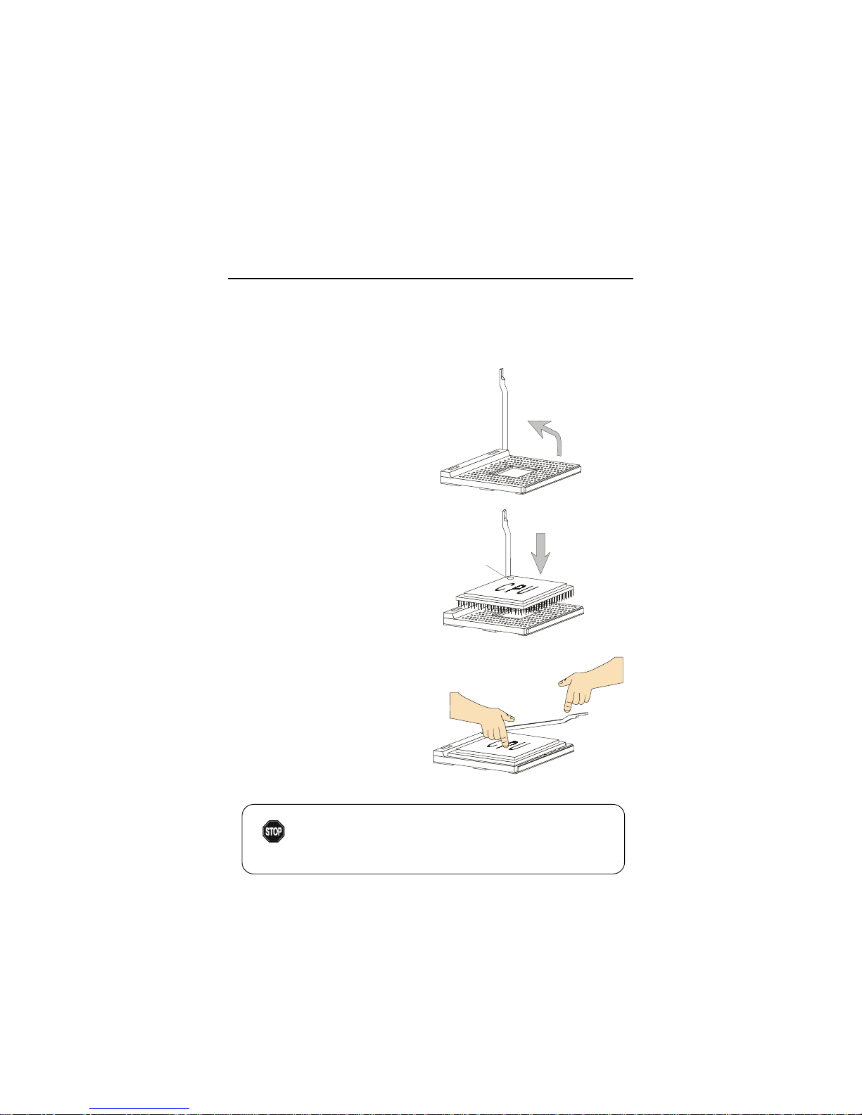
Central Processing Unit: CPU
The mainboard supports Intel® Pentium® 4 processor in the 478 pin
package. The mainboard uses a CPU socket called PGA478 for easy CPU
installation. When you are installing the CPU, make sure the CPU has a heat
sink and a cooling fan attached on the top to prevent overheating. If you do not
find the heat sink and cooling fan, contact your dealer to purchase and install
them before turning on the computer.
Overheating will seriously damage the CPU and system,
always make sure the cooling fan can work properly to
protect the CPU from overheating.
WARNING!
1. Pull the lever sideways away
from the socket. Then, raise
the lever up to a 90-degree
angle.
2. Look for the dot/cut edge. The
dot/cut edge should point towards the lever pivot. The
CPU will only fit in the correct
orientation.
3. Press the CPU down firmly
into the socket and close the
lever. As the CPU is likely to
move while the lever is being
closed, always close the lever
with your finger pressing
tightly on top of the CPU to
make sure the CPU is properly
& completely embedded into
the socket.
CPU Installation Procedures
Open Lever
Dot / Cut edge
Sliding
Plate
Close
Lever
Press down
the CPU
Page 7

Hardware Setup
2-3
CPU Core Speed Derivation Procedure
If CPU Clock = 100MHz
Core/Bus ratio = 14
then CPU core speed = Host Clock x Core/Bus ratio
= 100MHz x 14
= 1.4GHz
Overclocking
This motherboard is designed to support overclocking.
However, please make sure your components are able to
tolerate such abnormal setting, while doing overclocking.
Any attempt to operate beyond product specifications is not
recommended. We do not guarantee the damages or risks
caused by inadequate operation or beyond product
specifications.
WARNING!
Page 8
Chapter 2
2-4
D
I
M
M
1
D
I
M
M
2
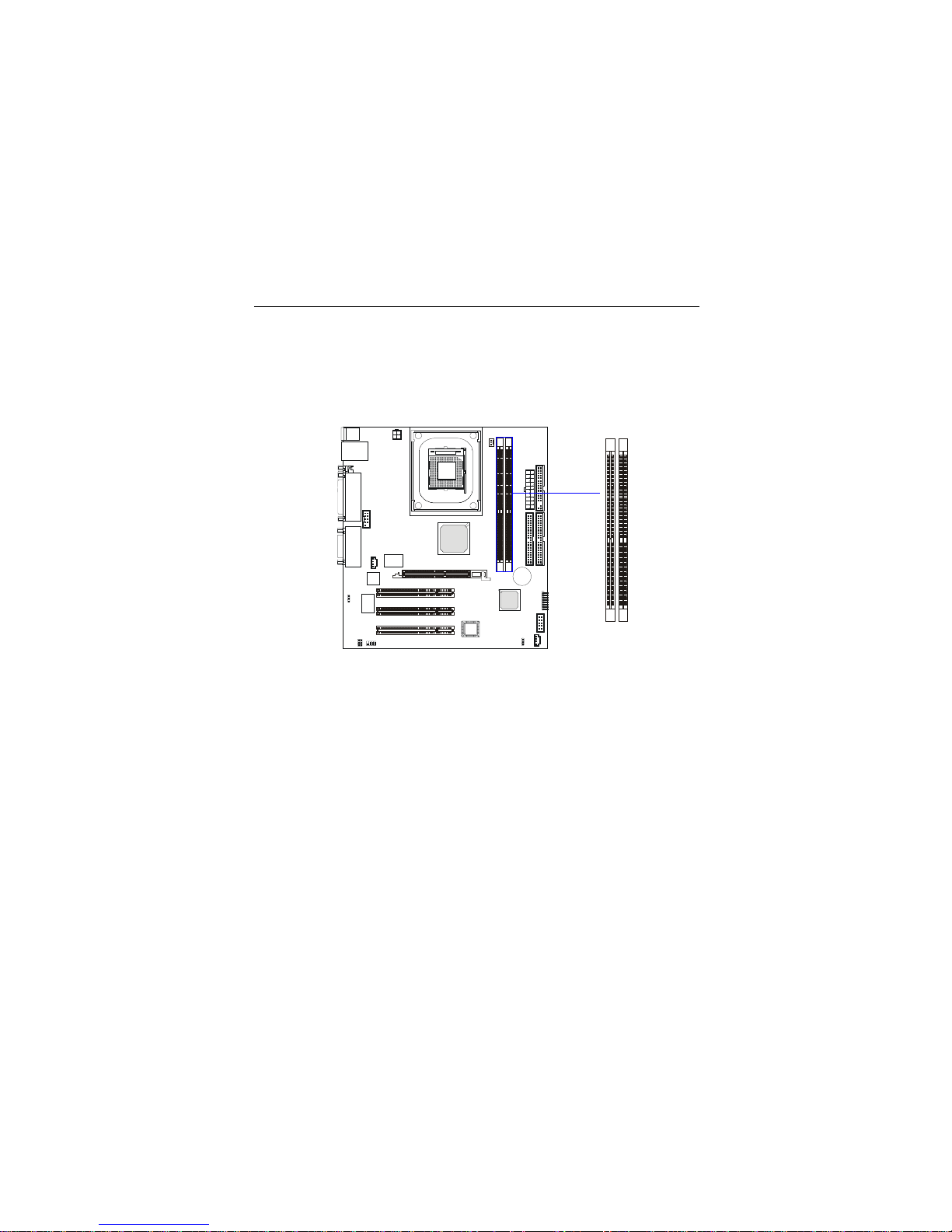
Memory
The mainboard provides 2 slots for 184-pin, 2.5V DDR DIMM with 4
memory banks. You can install DDR200/PC1600 or DDR266/PC2100 DDR
SDRAM modules on the DDR DIMM slots (DIMM 1~2). To operate properly,
at least one DIMM module must be installed.
Introduction to DDR SDRAM
DDR (Double Data Rate) SDRAM is similar to conventional SDRAM,
but doubles the rate by transferring data twice per cycle. It uses 2.5 volts as
opposed to 3.3 volts used in SDR SDRAM, and requires 184-pin DIMM modules rather than 168-pin DIMM modules used by SDR SDRAM. Two types of
DDR are available at the time of writing: PC1600 & PC2100. PC1600 DDR SDRAM
running at 100MHz will produce about 1.6GB/s memory bandwidth. PC2100
running at 133MHz will produce 2.1GB/s memory bandwidth. High memory
bandwidth makes DDR an ideal solution for high performance PC, workstations and servers.
Page 9

Hardware Setup
2-5
DDR Module Combination
You can install either single sided or double sided 184-pin DDR DIMM
modules into DDR DIMM slots to meet your needs. Different from the SDR
DIMM, the DDR DIMM has only one notch on the center of module. The
number of pins on either side of the breaks are different. The module will only
fit in the right orientation.
You can install memory modules in any combination as follows:
S: Single Side D: Double Side
Slot Memory Module Total Memory
DIMM 1
(Bank 0 & 1)
S/D 64MB~1GB
DIMM 2
(Bank 2 & 3)
S/D 64MB~1GB
Maximum System Memory Supported
64MB~2GB
Installing DDR Modules
1. The DDR DIMM has only one notch on the center of module. The module
will only fit in the right orientation.
2. Insert the DIMM memory module vertically into the DIMM slot. Then
push it in until the golden finger on the memory module is deeply inserted
in the socket.
3. The plastic clip at each side of the DIMM slot will automatically close.
Volt
Notch
How do I know if I have installed the memory modules correctly?
TIP: Y ou can barely see the golden finger if the module is deeply inserted in the socket.
Page 10

Chapter 2
2-6
Power Supply
The mainboard supports ATX power supply for the power system. Before inserting the power supply connector, always make sure that all components are installed properly to ensure that no damage will be caused.
A TX 20-Pin Power Connector
This connector allows you to connect to an ATX power supply. To
connect to the ATX power supply, make sure the plug of the power supply is
inserted in the proper orientation and the pins are aligned. Then push down
the power supply firmly into the connector.
A TX 12V Power Connector: JPW1
This 12V power connector is used to provide power to the CPU.
PIN SIGNAL
1 GND
2 GND
3 12V
4 12V
JPW1 Pin Definition
PIN SIGNAL
11 3.3V
12 -12V
13 GND
14 PS_ON
15 GND
16 GND
17 GND
18 -5V
19 5V
20 5V
PIN SIGNAL
1 3.3V
2 3.3V
3 GND
45V
5 GND
65V
7 GND
8 PW_OK
9 5V_SB
10 12V
ATX Power Supply Pin Definition
JPW1
1
3
2
4
10
1
20
11
Page 11

Hardware Setup
2-7
The Back Panel provides the following connectors:
Back Panel
Mouse Connector: JKBMS1
The mainboard provides a standard PS/2® mouse mini DIN connector for
attaching a PS/2® mouse. You can plug a PS/2® mouse directly into this
connector. The connector location and pin assignments are as follows:
Mouse
Keyboard USB
Parallel
COM A
SPDIF
IN
Line-in
Midi/Joystick
PIN SIGNAL DESCRIPTION
1 Mouse DATA Mouse DATA
2 NC No connection
3 GND Ground
4 VCC +5V
5 Mouse Clock Mouse clock
6 NC No connection
Pin Definition
PS/2 Mouse (6-pin Female)
2
1
3
4
5
6
LAN
SPDIF
OUT
Line-out (Front)
(2-channel output speaker)
Line-out (Rear)
(2-channel output speaker)
Center / Bass
(2-channel output speaker)
Page 12

Chapter 2
2-8
Keyboard Connector: JKBMS1
The mainboard provides a standard PS/2® keyboard mini DIN connector
for attaching a PS/2® keyboard. You can plug a PS/2® keyboard directly into
this connector.
USB Connectors
The mainboard provides a UHCI (Universal Host Controller Interface)
Universal Serial Bus root for attaching USB devices such as keyboard, mouse
or other USB-compatible devices. You can plug the USB device directly into
the connector.
PIN SIGNAL DESCRIPTION
1 Keyboard DATA Keyboard DAT A
2 NC No connection
3 GND Ground
4 VCC +5V
5 Keyboard Clock Keyboard clock
6 NC No connection
Pin Definition
USB Ports
1 2 3 4
5 6 7 8
PS/2 Keyboard (6-pin Female)
2
1
3
4
5
6
PIN SIGNAL DESCRIPTION
1 VCC +5V
2 -Data 0 Negative Data Channel 0
3 +Data0 Positive Data Channel 0
4 GND Ground
5 VCC +5V
6 -Data 1 Negative Data Channel 1
7 +Data 1 Positive Data Channel 1
8 GND Ground
USB Port Description
Page 13

Hardware Setup
2-9
Serial Port Connector: COM A & COM B1
The mainboard offers two 9-pin male DIN connectors for serial port COM
A and COM B1. The ports are 16550A high speed communication ports that
send/receive 16 bytes FIFOs. You can attach a serial mouse or other serial
devices directly to them.
PIN SIGNAL DESCRIPTION
1 DCD Data Carry Detect
2 SIN Serial In or Receive Data
3 SOUT Serial Out or Transmit Data
4 DTR Data Terminal Ready
5 GND Ground
6 DSR Data Set Ready
7 RTS Request To Send
8 CTS Clear T o Send
9 RI Ring Indicate
Pin Definition
9-Pin Male DIN Connectors
1 2 3 4
6 7 8 9
COM A
1 2 3 4 5
6 7 8 9
COM B1
LAN (RJ-45) Jack
The mainboard provides one standard RJ-45 jack for connection to Local
Area Network (LAN). Y ou can connect a network cable to the LAN jack.
Pin Definition
PIN SIGNAL DESCRIPTION
1 TDP Transmit Differential Pair
2 TDN Transmit Differential Pair
3 RDP Receive Differential Pair
4 NC Not Used
5 NC Not Used
6 RDN Receive Differential Pair
7 NC Not Used
8 NC Not Used
Page 14

Chapter 2
2-10
Joystick/Midi Connectors
You can connect a joystick or game pad to this connector.
SPDIF Connectors
The SPDIF connectors privided on the back pannel can be used to connect your digital audio equipment.
SPDIF
IN
SPDIF
OUT
Audio Port Connectors
Line In is used for external CD
player, tape player, or other audio
devices. Line Out are connectors for
speakers or headphones. Center/Bass
is a connector for audio device which is
used as a center speaker or supports
bass effect.
Line-in
Line-out (Front)
(2-channel output speaker)
Line-out (Rear)
(2-channel output speaker)
Center / Bass
(2-channel output speaker)
Page 15

Hardware Setup
2-11
Parallel Port Connector: LPT1
The mainboard provides a 25-pin female centronic connector as LPT. A
parallel port is a standard printer port that supports Enhanced Parallel Port
(EPP) and Extended Capabilities Parallel Port (ECP) mode.
13 1
14
25
PIN SIGNAL DESCRIPTION
1 STROBE Strobe
2 DAT A0 Data0
3 DAT A1 Data1
4 DAT A2 Data2
5 DAT A3 Data3
6 DAT A4 Data4
7 DAT A5 Data5
8 DAT A6 Data6
9 DAT A7 Data7
10 ACK# Acknowledge
11 BUSY Busy
12 PE Paper End
13 SELECT Select
14 AUTO FEED# Automatic Feed
15 ERR# Error
16 INIT# Initialize Printer
17 SLIN# Select In
18 GND Ground
19 GND Ground
20 GND Ground
21 GND Ground
22 GND Ground
23 GND Ground
24 GND Ground
25 GND Ground
Pin Definition
Page 16

Chapter 2
2-12
The mainboard provides connectors to connect to FDD, IDE HDD, case,
LAN, USB Ports, and CPU/System FAN.
Floppy Disk Drive Connector: FDD1
The mainboard provides a standard floppy disk drive connector that
supports 360K, 720K, 1.2M, 1.44M and 2.88M floppy disk types.
Connectors
FDD1
Page 17

Hardware Setup
2-13
Hard Disk Connectors: IDE1 & IDE2
The mainboard has a 32-bit Enhanced PCI IDE and Ultra DMA 33/66/100
controller that provides PIO mode 0~4, Bus Master, and Ultra DMA/33/66/100
function. You can connect up to four hard disk drives, CD-ROM, 120MB
Floppy (reserved for future BIOS) and other devices. These connectors support the provided IDE hard disk cable.
IDE1 (Primary IDE Connector)
The first hard drive should always be connected to IDE1. IDE1 can
connect a Master and a Slave drive. You must configure second hard
drive to Slave mode by setting the jumper accordingly.
IDE2 (Secondary IDE Connector)
IDE2 can also connect a Master and a Slave drive.
TIP:
If you install two hard disks on cable, you must configure the
second drive to Slave mode by setting its jumper. Refer to the
hard disk documentation supplied by hard disk vendors for
jumper setting instructions.
I
D
E
1
I
D
E
2
Page 18

Chapter 2
2-14
CD-In Connector: CD_IN1
The connector is for CD-ROM audio connector.
Front Audio Line-out Connector: JAUDIO1
The connector is for front audio output devices.
CD_IN1
GND
R
L
JAUDIO1
GND
AUXR
AUXL
MIC
Page 19

Hardware Setup
2-15
Fan Power Connectors: C_F AN1
The C_F AN1 (processor fan) supports system cooling fan with +12V. It
supports three-pin head connector. When connecting the wire to the
connectors, always take note that the red wire is the positive and should be
connected to the +12V, the black wire is Ground and should be connected to
GND. If the mainboard has a System Hardware Monitor chipset on-board, you
must use a specially designed fan with speed sensor to take advantage of the
CPU fan control.
Note:
1. Always consult the vendor for proper CPU cooling fan.
2. CPU Fan supports the fan control. You can install the PC Alert
utility that will automatically control the CPU Fan speed according to the actual CPU temperature.
C_FAN1
SENSOR
+12V
GND
Page 20

Chapter 2
2-16
Front Panel Connectors: F_P1
The mainboard provides one front panel connector for electrical connec-
tion to the front panel switches and LEDs
F_P1
HDD LED
Reset Switch
Power LED
Power Switch
Page 21

Hardware Setup
2-17
Front USB Connector: USB1
The mainboard provides one front Universal Serial Bus connector for
users to connect USB devices.
Pin Description Pin Description
1 USBPWR 2 GND
3 USBDT2- 4 GND
5 USBDT2+ 6 USBDT3+
7 GND 8 USBDT39 GND 10 USBPWR
USB1 Pin Definition
USB1
1 2
9 10
Page 22

Chapter 2
2-18
SPDIF Connector: JSPDIF1
The connector is used to connect an optional bracket for SPDIF (Sony &
Philips Digital Interconnect Format) digital audio transmission.
Pin Description Pin Description
1 +12V 2 NC
3 NC 4 SPDIFO
5 SPDIFI 6 GND
7 SPDIF2 8 SPGPIO
JSPDIF1 Pin Definition
JSPDIF1
127
8
Page 23

Hardware Setup
2-19
The motherboard provides the following jumpers for you to set the
computer’s function. This section will explain how to change your
motherboard’s function through the use of these jumpers.
Clear CMOS Jumper: JBA T1
There is a CMOS RAM on board that has a power supply from external
battery to keep the data of system configuration. With the CMOS RAM, the
system can automatically boot OS every time it is turned on. If you want to
clear the system configuration, use the JBAT1 (Clear CMOS Jumper ) to clear
data. Follow the instructions below to clear the data:
You can clear CMOS by shorting 2-3 pin while the
system is off. Then return to 1-2 pin position. Avoid
clearing the CMOS while the system is on; it will damage the mainboard.
WARNING!
JBAT1
1
Jumpers
Keep Data
3
1
Clear Data
3
1
Page 24

Chapter 2
2-20
JLAN1
1
LAN Enable/Disable Jumper: JLAN1
This jumper is used to enable/disable the onboard LAN controller.
LAN Enable
3
1
LAN Disable
3
1
Page 25

Hardware Setup
2-21
Center/Bass Setting Jumper: J11 & J12
The mainboard comes with two jumpers for users to set up their center or
bass speaker. If you connect a pair of speakers which supports bass through
the Center/Bass audio connector (refer to P.2-11), you may need to set up
which speaker can output bass in order to get a better sound effect. If you
merely connect a single center or bass speaker, the setting of these two jumpers will be invalid. Follow the instructions below to set up the speakers:
J11
131
3
J12
Set the center speaker to
the left and woofer to the
right.
3
1
3
1
3
1
3
1
Set the center speaker to
the right and woofer to the
left.
Page 26

Chapter 2
2-22
Slots
AGP (Accelerated Graphics Port) Slot
The AGP slot allows you to insert the AGP graphics card. AGP is an
interface specification designed for the throughput demands of 3D graphics.
It introduces a 66MHz, 32-bit channel for the graphics controller to directly
access main memory and provides three levels of throughputs: 1x (266Mbps),
2x (533Mbps) and 4x (1.07Gbps). Please especially note that, for enhanced 3D
visualization, Intel® 845 chipset supports the latest graphics devices through
1.5V AGP 4X interface. No 3.3V AGP 2X interface is supported. Installing
3.3V AGP 2X cards on Intel® 845 based mainboards will damage the mainboards.
PCI Slots
Three PCI slots allow you to insert the expansion cards to meet your
needs. When adding or removing expansion cards, make sure that you unplug
the power supply first. Meanwhile, read the documentation for the expansion
card to make any necessary hardware or software settings for the expansion
card, such as jumpers, switches or BIOS configuration.
The motherboard provides three 32-bit Master PCI bus slots and one
AGPslot.
PCI Slots
AGP Slot
Page 27

Hardware Setup
2-23
Order 1 Order 2 Order 3 Order 4
PCI Slot 1 INT A# INT B# INT C# INT D#
PCI Slot 2 INT B# INT C# INT D# INT A#
PCI Slot 3 INT C# INT D# INT A# INT B#
PCI Interrupt Request Routing
The IRQ, acronym of interrupt request line and pronounced I-R-Q, are
hardware lines over which devices can send interrupt signals to the
microprocessor. The PCI IRQ pins are typically connected to the PCI bus INT
A# ~ INT D# pins as follows:
 Loading...