

Page 1

Have a question or need assistance?
TelePatch™
TelePatch is intended for use as prescribed by a physician who wants to follow
cardiac activity. TelePatch is not intended for diagnostic use. A physician must
TelePatch™ Cardiac Monitor PM750
Call Medicomp’s Patient Support: 877-996-5553
Cardiac Monitor PM750
User Manual
INSTRUCTIONS FOR USE
review and interpret ECG findings recorded during procedure.
USER MANUAL - UTM0000701-05E
1
| APRIL 4, 2019
Page 2

Have a question or need assistance?
TelePatch™ Cardiac Monitor PM750
Call Medicomp’s Patient Support: 877-996-5553
Table of Contents
GETTING STARTED AND INTRODUCTION 6
Notices, Cautions, and Copyrights 6
TelePatch Cardiac Monitor User Kit 7
Contact Us 9
ABOUT TELEPATCH CARDIAC MONITOR PM750 10
INDICATIONS FOR USE 10
OVERVIEW 11
SAFETY SPECIFICATIONS AND COMPLIANCE 11
Contraindication 11
Safety Classification 11
Modifications 11
Defibrillation 11
System Safety 11
COMPLIANCE 12
Safety Classification 12
Radio Frequency Regulatory Compliance 12
BUTTONS, ICONS AND SCREEN INDICATOR DESCRIPTION 13
TELEPATCH SYSTEM OVERVIEW 15
Universal Pendant Description 17
TelePatch Handset Description 20
Accessories to the TelePatch System 21
TelePatch Charger Cord 22
Connecting Charger Cord: Handset 24
TelePatch Battery Charger 26
Connecting Charger Cord To Battery Charger: 27
TelePatch Electrode Patch 29
STANDARD PROCEDURE SET-UP 32
Patient Preparation 32
Step 1 - Identify Electrode Patch Site 32
Step 2 - Prepare the Skin 33
Step 3 - Electrode Patch Application 34
USER MANUAL - UTM0000701-05E
2
| APRIL 4, 2019
Page 3

Have a question or need assistance?
TelePatch™ Cardiac Monitor PM750
Call Medicomp’s Patient Support: 877-996-5553
Step 4 - Turn on Pendant and Connect 35
Step 5 - Starting the Handset 38
Step 6 - Procedure Set Up 39
Step 7 - Procedure Settings 39
Pacemaker Settings 40
Protocol Setting 41
Set Up 42
Start Over: 42
Step 8 - Initial Procedure Screens 43
Recording Symptoms: Standard TelePatch Procedure 45
Manual Diary Entry: 46
Audio Diary Entry: 47
PROCEDURE SET-UP: Cable Cradle with Patient Cable 47
Step 1 - Identify Electrode Sites 48
Step 2 - Prepare the Skin 49
Step 3 - Snap on Electrodes and Set Up Cable Cradle 50
Step 4 - Start Pendant: 52
Step 5 - Starting the Handset: 52
Step 6 - Procedure Set Up: 52
Step 7 - Procedure Settings: 52
Step 8 - Initial Procedure Screens: 52
Recording Symptoms: Cable Cradle Procedure 52
PROCEDURE SET-UP: Fingertip Electrodes 53
Step 1 - Start Pendant: 53
Step 2 - Starting the Handset: 53
Step 3 - Procedure Set Up: 53
Step 4 - Procedure Settings: 53
Step 5 - Initial Procedure Screens: 53
Recording Symptoms: Fingertip Electrode Procedure 53
COMMON QUESTIONS 54
How Do I Wear TelePatch System: Electrode Patch and Pendant? 54
How Do I Wear TelePatch System: Pendant, Cable Cradle With Electrodes? 55
Can I Shower? 55
Tip For During Shower 55
Tip For After Shower 55
Stress Loops 56
USER MANUAL - UTM0000701-05E
| APRIL 4, 2019
3
Page 4

Have a question or need assistance?
TelePatch™ Cardiac Monitor PM750
Call Medicomp’s Patient Support: 877-996-5553
EMERGENCY AND SUPPORT NUMBERS 56
Call 911 56
PROCEDURE INFORMATION AND CAUTIONS 57
TELEPATCH SYSTEM WHEN WEARING ELECTRODE PATCH 57
SHOWERING OR SWIMMING WITH TELEPATCH SYSTEM AND ELECTRODE PATCH 57
TELEPATCH SYSTEM WHEN USING CABLE CRADLE 58
SHOWERING OR SWIMMING WITH TELEPATCH SYSTEM AND CABLE CRADLE 58
ANDSET / HANDSET 59
H
BATTERY CHARGER 59
PENDANT PRECAUTIONS 60
ADVERSE REACTIONS 60
MAINTENANCE 61
Cleaning the TelePatch System 61
VISUAL AND AUDIBLE INDICATORS 61
Normal Performance Indicators 61
Error Indicators 62
TROUBLESHOOTING 63
Setup Details and Troubleshooting Overview 63
TelePatch System Hookup Testing Information 64
Quality Hookup Tests Overview 64
The Setup/Normal Setting 64
Pacemakers 64
Lead Position Test 65
Skin Prep Results 65
Error Displays 65
Voltage Errors after Several Attempts 66
Lead Position Tests 66
Lead Test Error 66
High/Low Voltage Notifications 67
LOW VOLTAGE IN CHANNEL A 67
LOW VOLTAGE IN CHANNEL B 68
HIGH VOLTAGE IN CHANNEL A 68
HIGH VOLTAGE IN CHANNEL B 68
SAMPLE SCREEN WARNINGS 69
Screen Warnings 69
USER MANUAL - UTM0000701-05E
| APRIL 4, 2019
4
Page 5

Have a question or need assistance?
TelePatch™ Cardiac Monitor PM750
Call Medicomp’s Patient Support: 877-996-5553
Unable to find Pendant 69
Pendant is Turned Off 69
Procedure Has Ended 69
Start Procedure Exceptions 70
Selecting a Pendant 70
SAFE BATTERY USE AND DISPOSAL 70
Safely Loading the Pendant Battery 71
Battery Maintenance 72
Disposal of Rechargeable Lithium Ion Batteries 72
EXPLANATION OF MARKINGS 73
EXPECTED LIFE 75
PENDANT SPECIFICATIONS 75
GUIDANCE AND MANUFACTURER’S DECLARATION - ELECTROMAGNETIC EMISSIONS 76
GUIDANCE AND MANUFACTURER’S DECLARATION - ELECTROMAGNETIC IMMUNITY 77
GUIDANCE AND MANUFACTURER’S DECLARATION - ELECTROMAGNETIC IMMUNITY 78
RECOMMENDED SEPARATION DISTANCES BETWEEN PORTABLE AND MOBILE RF
COMMUNICATIONS EQUIPMENT AND THE PM750 79
USER MANUAL - UTM0000701-05E
5
| APRIL 4, 2019
Page 6

Have a question or need assistance?
CAUTION: FEDERAL LAW RESTRICTS TELEPATCH CARDIAC MONITOR PM750 FOR
THIS TELEPATCH CARDIAC MONITOR PM750 IS NOT INTENDED FOR USE BY USERS WHO ARE
TelePatch™ Cardiac Monitor PM750 is a product of Medicomp, Inc.
Medicomp, Inc. is the manufacturer and provider of TelePatch products and services. TelePatch
TelePatch™ Cardiac Monitor PM750
Call Medicomp’s Patient Support: 877-996-5553
GETTING STARTED AND INTRODUCTION
Notices, Cautions, and Copyrights
SALE BY, OR ON THE ORDER OF, A LICENSED MEDICAL PRACTITIONER. THE DATA
OBTAINED FROM THE PENDANT IS FOR THE REVIEW BY A PHYSICIAN. IT IS
RECOMMENDED THAT A PHYSICIAN OVERREAD THE RESULTS.
UNABLE TO ACTIVATE THE SYMPTOM BUTTON WHEN THEY ARE EXPERIENCING A SYMPTOM.
USERS SHOULD BE SUPERVISED IF UNABLE TO ACTIVATE THE SYMPTOM BUTTON ON THEIR
OWN.
is a trademark of Medicomp, Inc. ©2019 Medicomp, Inc. All rights reserved.
NO PART OF THIS PUBLICATION MAY BE REPRODUCED OR DISTRIBUTED IN ANY FORM OR BY
MEANS WITHOUT PRIOR WRITTEN PERMISSION FROM MEDICOMP, INC.
USER MANUAL - UTM0000701-05E
6
| APRIL 4, 2019
Page 7
Have a question or need assistance?
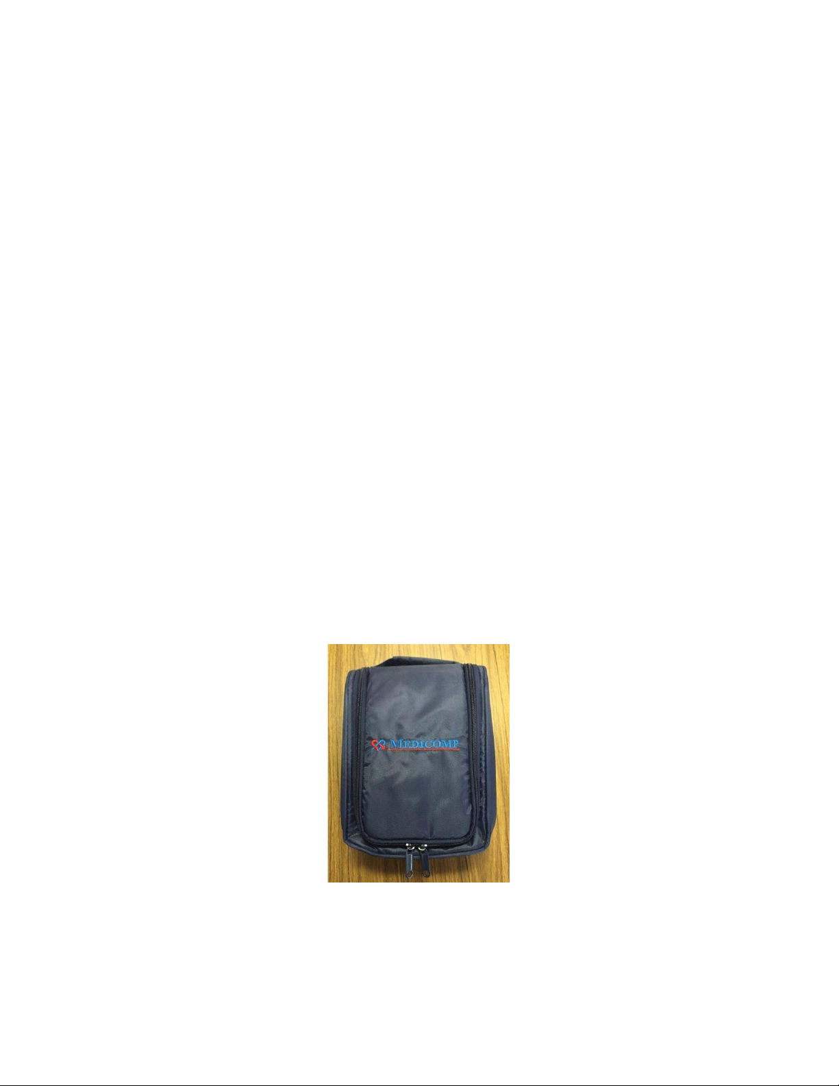
TelePatch Cardiac Monitor User Kit
The standard TelePatch Cardiac Monitor PM750 kit comes with:
4. TelePatch Handset
TelePatch Cardiac Monitor Kit
TelePatch™ Cardiac Monitor PM750
Call Medicomp’s Patient Support: 877-996-5553
1. Universal Pendant
2. Electrode Patch with Cradle
3. Rechargeable Batteries
5. Battery Charger
6. Charger Cord for both Handset and Battery Charger
7. Electrode Prep Pad
8. Quick Start Patient Guide
9. Survey Invitation
10. Return Envelope with Prepaid Shipping Label
11. Legal Booklet
USER MANUAL - UTM0000701-05E
7
| APRIL 4, 2019
Page 8
Have a question or need assistance?
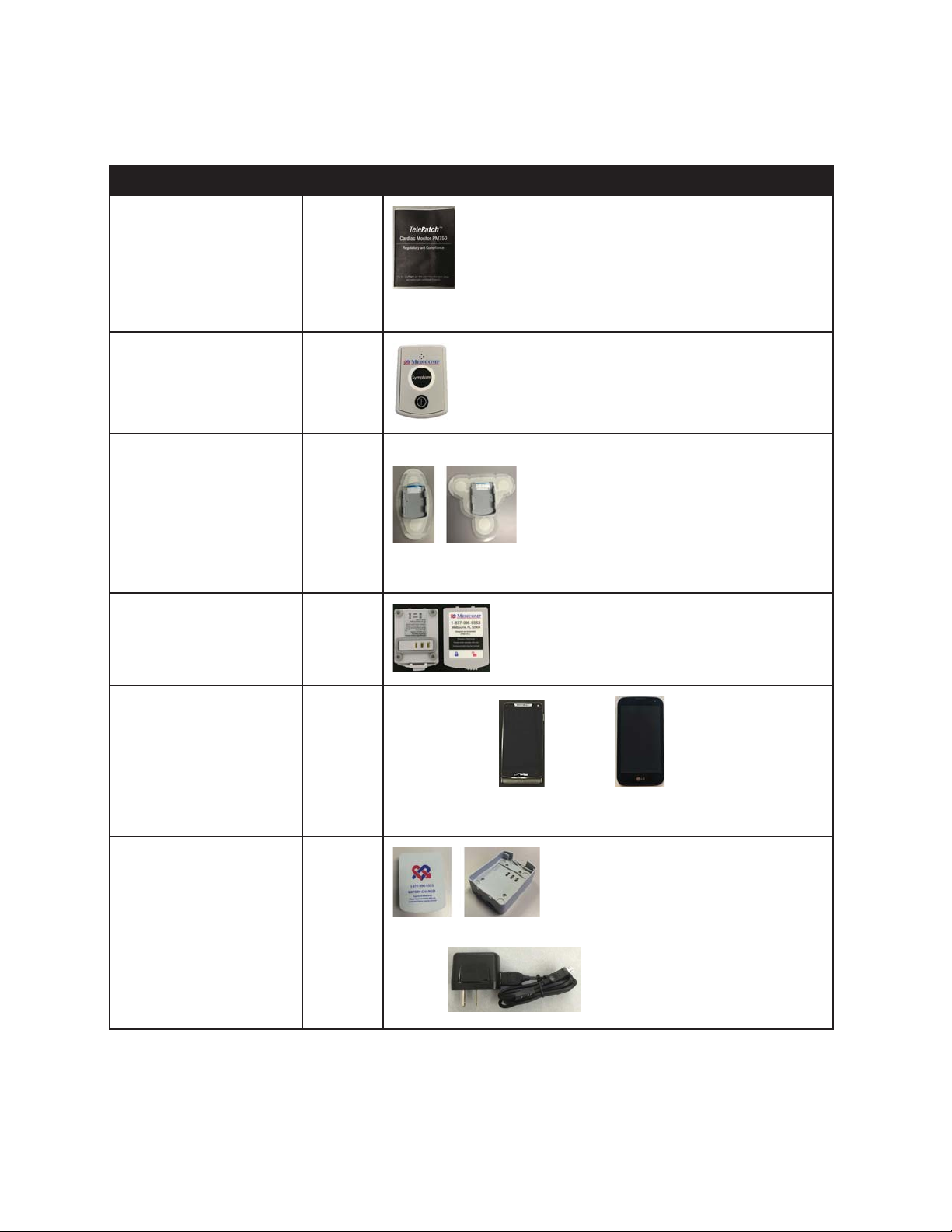
TELEPATCH KIT CONTENTS
Quantity
TelePatch
with Cradle*
TelePatch
TelePatch™ Cardiac Monitor PM750
Call Medicomp’s Patient Support: 877-996-5553
Item
Legal Booklet 1
Pendant 1
Electrode Patch
1 - 4
Picture
*Kit will have one or the other patch style, single or dual is based on
procedure prescribed by physician
Rechargeable Battery 2
Handset* 1
Battery Charger 1
Charger Cord
for Handset
and Battery Charger 1
USER MANUAL - UTM0000701-05E
8
Motorola: LG:
*Holter procedures do not require a Handset
| APRIL 4, 2019
Page 9
Have a question or need assistance?
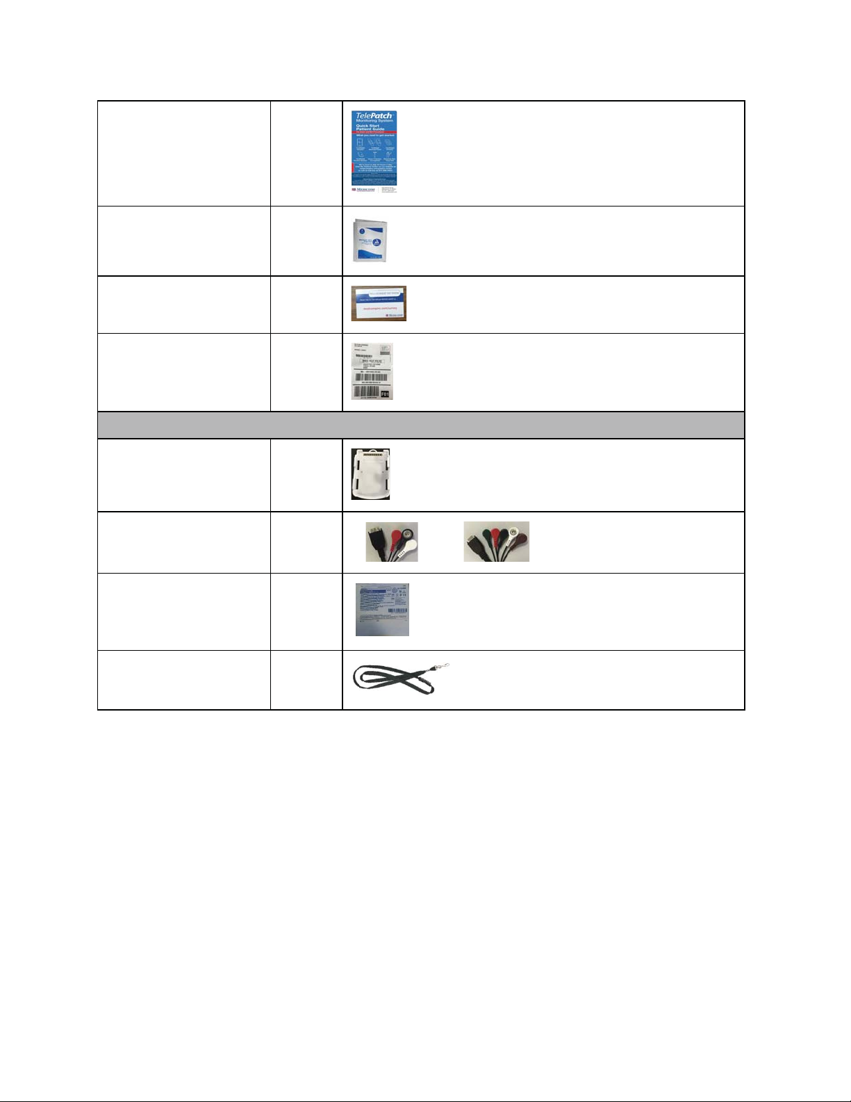
Prepaid Shipping Label
Contact Medicomp, Inc. for any issues concerning the TelePatch product such as:
TelePatch™ Cardiac Monitor PM750
Call Medicomp’s Patient Support: 877-996-5553
Quick Start
Patient Guide 1
Electrode Prep Pad 1
Survey Invitation 1
Return Envelope with
Cable Cradle 1
Cable
3-lead or 5-lead 1
Electrodes
(3-5 per pouch) 1- 4
1
Breakaway Lanyard 1
Contact Us
• General questions about our product
• Product safety
• Safe disposal of component parts
• Return of product
Contact information
Medicomp, Inc. Telephone: 800-23 HEART (800-234-3278)
USER MANUAL - UTM0000701-05E
9
| APRIL 4, 2019
Page 10
Have a question or need assistance?
ABOUT TELEPATCH CARDIAC MONITOR PM750
TelePatch™ Cardiac Monitor PM750
Call Medicomp’s Patient Support: 877-996-5553
600 Atlantis Rd.
Fax: 321-676-2282
Melbourne, FL, 32904
Website: www.medicompinc.com
email: [email protected]
INDICATIONS FOR USE
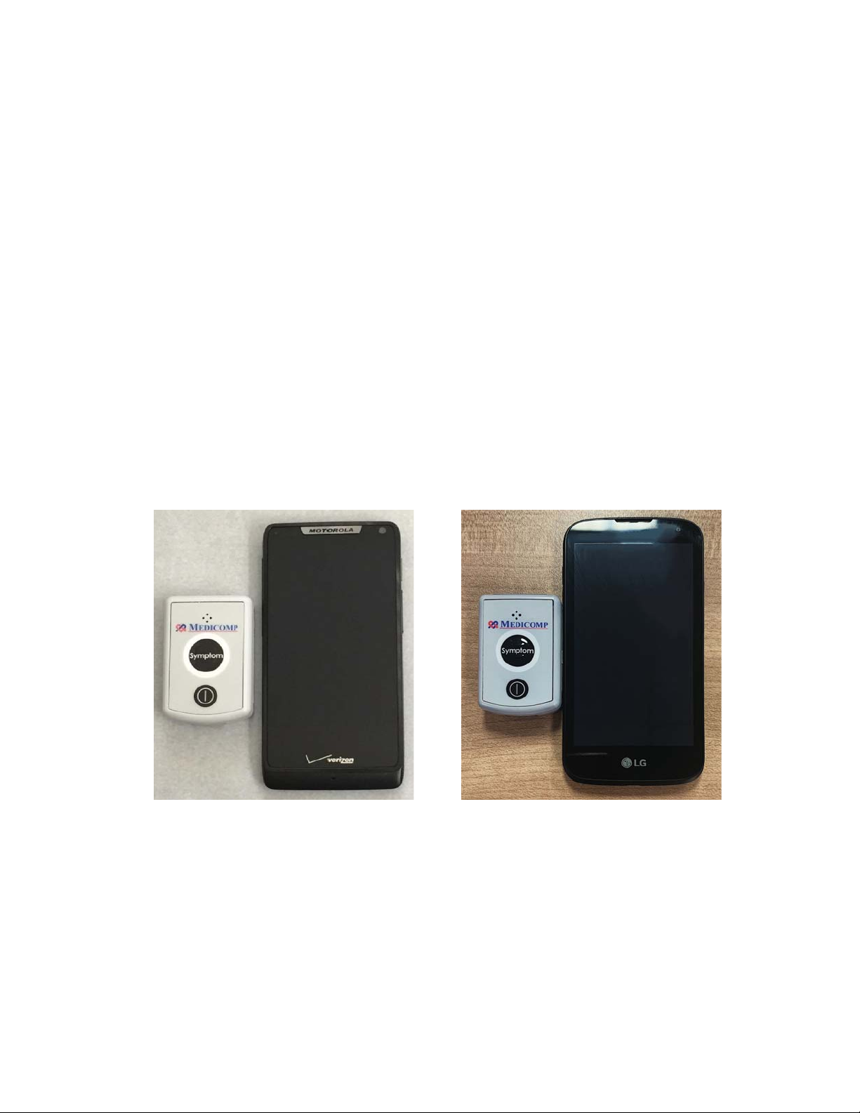
The TelePatch Cardiac Monitor PM750, is a pager-sized, handheld or patient worn device
designed specifically to record and transmit ambulatory ECG signals. The device is designated as
Rx only, to be worn by infants to adults of all ages. The device can be worn for days or weeks, as
it is intended for use by patients who are experiencing symptoms that are transient and
infrequent in nature.
Motorola:
LG:
USER MANUAL - UTM0000701-05E
10
| APRIL 4, 2019
Page 11

Have a question or need assistance?
The TelePatch Cardiac Monitor System
Users of the TelePatch System should be able to activate the Symptom button unassisted or be
supervised and assisted. The TelePatch System can be worn by users weighing less than 10kg.
TelePatch is intended for use as prescribed by a physician who wants to follow cardiac activity.
There are no potential adverse effects of the TelePatch Cardiac Monitor, PM750 on health.
This equipment shall not be used in the presence of a flammable anesthetic mixture with air or with oxygen or nitrous oxide, or
TelePatch System Shipment: Temperature limitation for shipment: -15°C to 60°C (5°F to 140°F).
Atmospheric Pressure: Operating: 700 hPa to 1060 hPa; Storage/Transport: Not Applicable to TelePatch System
The external parts of the equipment may provide a source of the defibrillation voltage if it is not removed from the patient during defibrillation.
shunted and make it less effective for the patient. The unit and cable MUST be removed prior to defibrillation.
processing equipment). Furthermore all configurations shall comply with the requirements for medical electrical systems (see IEC 60601-1-1 or
medical system and is therefore responsible that the system complies with the requirements for medical electrical systems. Attention is drawn
TelePatch™ Cardiac Monitor PM750
Call Medicomp’s Patient Support: 877-996-5553
OVERVIEW
A physician must review and interpret ECG findings recorded during procedure. The TelePatch
System is not intended for diagnostic use.
SAFETY SPECIFICATIONS AND COMPLIANCE
Contraindication
Safety Classification
In accordance with IEC 60601-1 Third Edition Am 1: 2012:
● This equipment is designed to be operated with one 3.7V 440mAh 1.62Wh lithium ion battery, and under no circumstances shall
power be supplied in any other manner.
● Type BF equipment.
● Rated for Continuous Operation.
● Ordinary Equipment. Enclosed equipment. The device is protected to IP55 as required by the standard.
●
flammable cleaning agents.
● Equipment with an Applied Part, specifically designed for applications where a Conductive Connection is made to the Patient, but
not directly to the heart.
● The equipment requires no adjustment.
● Operating and Storage Humidity: 10% to 95%, non-condensing
● Operating Temperature: 0°C to 45°C (32°F to 284°F).
● Storage Temperature: -15°C to 60°C (5°F to 140°F).
●
●
The equipment contains no user-serviceable parts. It shall be serviced only by Medicomp, Inc. Unauthorized repairs of the equipment will void
the warranty.
Modifications
For continued safety, equipment should not be modified in any manner and must be used only as indicated.
Defibrillation
Due to the small size of the unit and patient connectors, the cable or connector may break down and cause the defibrillation voltage to be
System Safety
Additional equipment connected to medical electrical equipment must comply with the respective IEC or ISO standards (e.g. IEC 60950 for data
clause 16 of the 3Ed. of IEC 60601-1, respectively). Anybody connecting additional equipment to medical electrical equipment configures a
USER MANUAL - UTM0000701-05E
| APRIL 4, 2019
11
Page 12

Have a question or need assistance?
OPERATION OF THESE PENDANTS INTERFERES WITH THE TELEPATCH’S ABILITY TO ACQUIRE THE ECG SIGNAL. IF ALLOWED THESE
LOAD ONLY 3.7V LITHIUM ION BATTERIES DELIVERED IN THE TELEPATCH KIT INTO THE TELEPATCH CARDIAC MONITOR BATTERY
ELECTRODE CONNECTION THROUGH A 4.9MOHM RESISTOR AT A RATE OF 15 HZ WITH RESPECT TO THE SYSTEM GROUND.
IN THE EVENT OF A DAMAGED PENDANT, DISCONTINUE USE AND CALL MEDICOMP PATIENT SUPPORT: 800-234-3278 EXT. 2370,
Conformance to Standards – non-clinical testing demonstrated conformance to voluntary safety IEC 60601-1 and to IEC 60601-1-2-2001 Class B
Non-clinical testing demonstrated conformance to voluntary safety IEC 60601-1 and to IEC 60601-1-2-2001 Class B
This Pendant complies with part 15 of the FCC Rules. Operation is subject to the following two conditions: (1) This Pendant may not cause
Note: This equipment has been tested and found to comply with the limits for a Class B digital Pendant, pursuant to part 15 of the FCC Rules.
uses and can radiate radio frequency energy and, if not installed and used in accordance with the instructions, may cause harmful interference
cause harmful interference to radio or television reception, which can be determined by turning the equipment off and on, the user is
TelePatch™ Cardiac Monitor PM750
Call Medicomp’s Patient Support: 877-996-5553
to the fact that local laws take priority over the above mentioned requirements. If in doubt, consult your local representative or the technical
service department.
● USE THE TELEPATCH SYSTEM ONLY WITH THE LEADS, ELECTRODES, AND ACCESSORIES RECOMMENDED BY MEDICOMP. USE OF
OTHER ACCESSORIES MAY ADVERSELY AFFECT THE PERFORMANCE OF THE DEVICE OR MAY RESULT IN STRONGER
ELECTROMAGNETIC EMISSIONS OR REDUCE THE ELECTROMAGNETIC IMMUNITY OF TELEPATCH CARDIAC MONITOR PM750.
● CONDUCTIVE PARTS OF ELECTRODES AND ASSOCIATED CONNECTORS FOR TYPE BF OR CF APPLIED PARTS, INCLUDING NEUTRAL
ELECTRODE, SHOULD NOT CONTACT OTHER CONDUCTIVE PARTS, INCLUDING EARTH.
● USERS WHO ARE WEARING NEUROSTIMULATING PENDANTS CANNOT BE SET UP WHILE THAT DEVICE IS TURNED ON. THE
DEVICES SHOULD BE TURNED OFF WHILE THE PATIENT IS WEARING TELEPATCH.
● DO NOT USE THE TELEPATCH IN COMBINATION WITH EXTERNAL CARDIAC DEFIBRILLATORS OR HIGH FREQUENCY SURGICAL
EQUIPMENT.
● PORTABLE AND MOBILE RF COMMUNICATIONS EQUIPMENT CAN AFFECT MEDICAL ELECTRICAL EQUIPMENT. THIS PENDANT
SHOULD NOT BE USED ADJACENT TO OR STACKED WITH OTHER EQUIPMENT.
●
COMPARTMENT.
● LEAD FAILURES ARE DETECTED BY A 10 MV PEAK, 50% DUTY CYCLE RECTANGULAR PULSE, WHICH IS APPLIED TO EACH PATIENT
● THIS IS A PRESCRIBED MEDICAL DEVICE, NOT A TOY, INFANTS AND CHILDREN MUST BE SUPERVISED.
● WARNING: CHOKING HAZARD – ADULT SUPERVISION REQUIRED.
●
FOR RETURN AND REPLACEMENT.
WARNINGS
COMPLIANCE
Safety Classification
In accordance with IEC 60601-1 Third Edition Am 1:2012 :
Medicomp, Inc.’s Quality System conforms to 21 CFR 820 and ISO 13485:2003.
Radio Frequency Regulatory Compliance
Conformance to Standards
Medicomp, Inc.’s Quality System conforms to 21 CFR 820 and ISO 13485:2003.
This Pendant contains transmitter module FCC ID:
Model Name: TAS0000750
FCC ID: 2AGDTPM700
IC account number/IC company number: 21061-PM700
CAN ICES-3 (B)/NMB-3(B)”
harmful interference, and (2) this Pendant must accept any interference received, including interference that may cause undesired operation.
Part 15 Clause 15.105
These limits are designed to provide reasonable protection against harmful interference in a residential installation. This equipment generates
to radio communications. However, there is no guarantee that interference will not occur in a particular installation. If this equipment does
encouraged to try to correct the interference by one or more of the following measures:
—Reorient or relocate the receiving antenna.
—Increase the separation between the equipment and receiver.
—Connect the equipment into an outlet on a circuit different from that to which the receiver is connected.
—Consult the dealer or an experienced radio/TV technician for help.
Part 15 Clause 15.21
USER MANUAL - UTM0000701-05E
12
| APRIL 4, 2019
Page 13
Have a question or need assistance?
Changes or modifications not expressly approved by the party responsible for compliance could void the user's authority to operate the
Pendant may not cause interference, and (2) this Pendant must accept any interference, including interference that may cause undesired
deux conditions suivantes: (1) l'appareil ne doit pas produire de brouillage, et (2) l'utilisateur de l'appareil doit accepter tout brouillage
Under Industry Canada regulations, this radio transmitter may only operate using an antenna of a type and maximum (or lesser) gain approved
that the equivalent isotropically radiated power (e.i.r.p.) is not more than that necessary for successful communication.
maximal (ou inférieur) approuvé pour l'émetteur par Industrie Canada. Dans le but de réduire les risques de brouillage radioélectrique à
Below is a detailed description of TelePatch Icons and Screen Indicators.
TELEPATCH Handset APPLICATION ONLY AND NOT FOR NORMAL CELLULAR PHONE USAGE.
TELEPATCH APPLICABLE BUTTONS
TelePatch™ Cardiac Monitor PM750
Call Medicomp’s Patient Support: 877-996-5553
equipment.
This Pendant complies with Industry Canada license-exempt RSS standard(s). Operation is subject to the following two conditions: (1) this
operation of the Pendant.
Le présent appareil est conforme aux CNR d'Industrie Canada applicables aux appareils radio exempts de licence. L'exploitation est autorisée aux
radioélectrique subi, même si le brouillage est susceptible d'en compromettre le fonctionnement. »
for the transmitter by Industry Canada. To reduce potential radio interference to other users, the antenna type and its gain should be so chosen
Conformément à la réglementation d'Industrie Canada, le présent émetteur radio peut fonctionner avec une antenne d'un type et d'un gain
l'intention des autres utilisateurs, il faut choisir le type d'antenne et son gain de sorte que la puissance isotrope rayonnée équivalente (p.i.r.e.) ne
dépasse pas l'intensité nécessaire à l'établissement d'une communication satisfaisante.
BUTTONS, ICONS AND SCREEN INDICATOR DESCRIPTION
USER GUIDE DESCRIPTIONS FOR SCREEN INDICATORS AND ICONS ARE FOR USE WITH THE
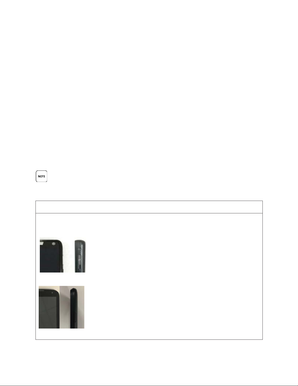
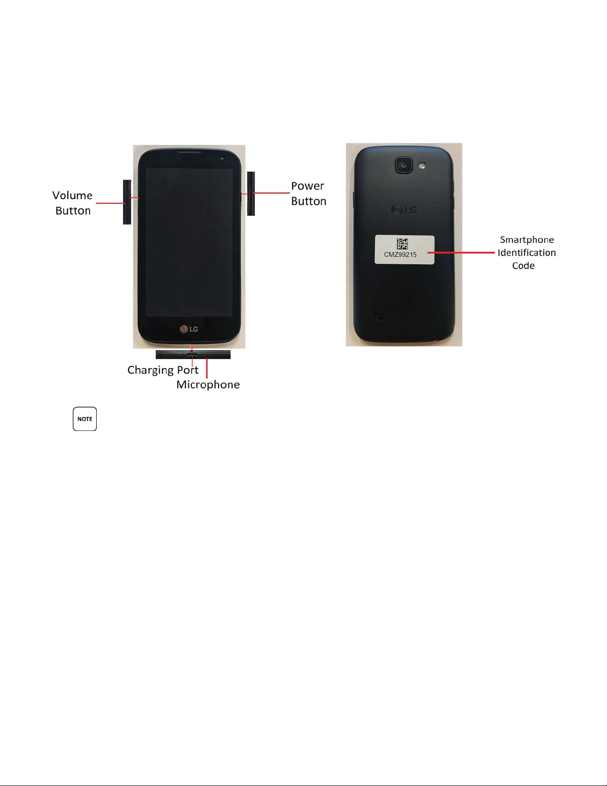
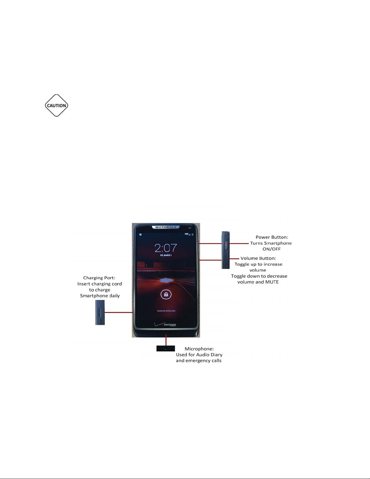
The Handset POWER Button
This is the Handset POWER button. It is located on the top, RIGHT side of the Handset.
Motorola Front and Side View
LG Front and Side View
USER MANUAL - UTM0000701-05E
13
| APRIL 4, 2019
Page 14
Have a question or need assistance?
The Handset Needs Charging Indicator
TELEPATCH APPLICABLE TOUCH KEYS - Handset
Initiates procedure for the TelePatch system.
FREQUENT SCREEN ICONS AND INDICATORS
TelePatch™ Cardiac Monitor PM750
Call Medicomp’s Patient Support: 877-996-5553
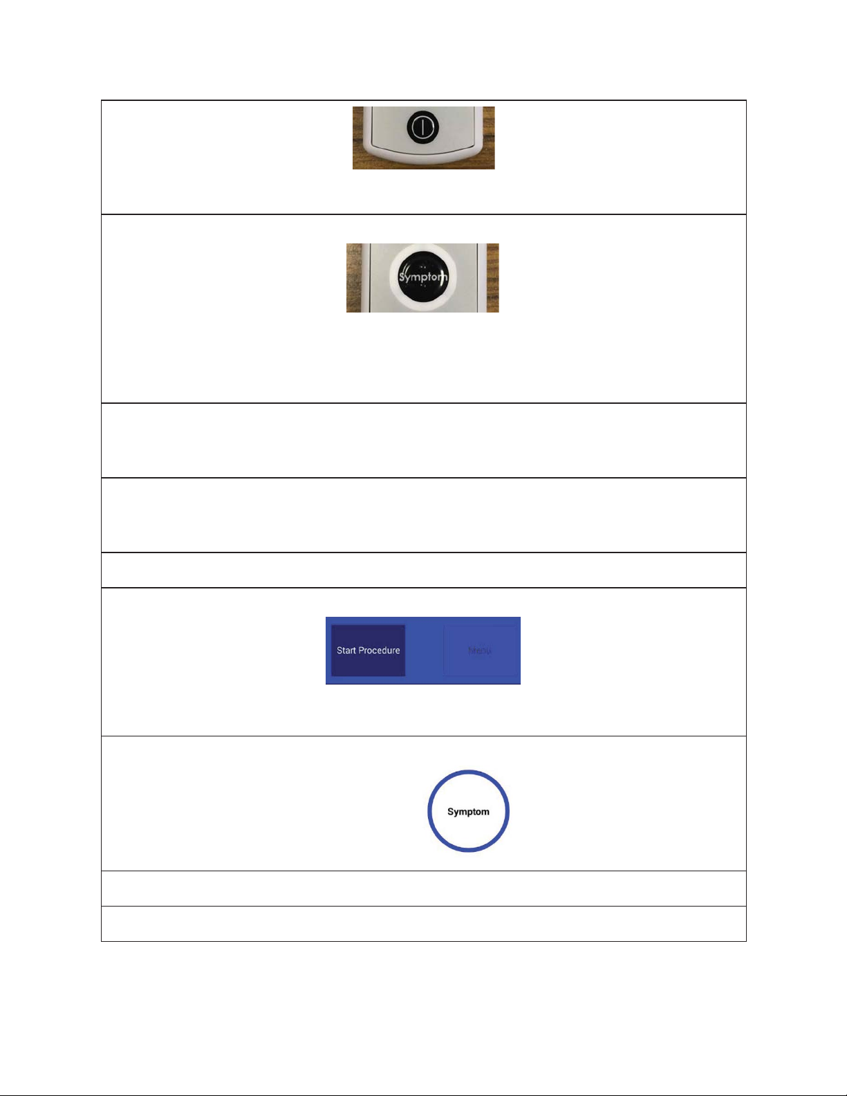
The Pendant POWER Button
This is the Pendant POWER button. It is located on the FACE of the Pendant.
The Pendant Symptom Button
This is the Pendant Symptom button. It is located in the center of the FACE of the Pendant.
Users push the Symptom* button to manually initiate the recording of symptoms that they
may be experiencing. (*Symptom capture can also be initiated on the Handset)
Handset will have red flashing LED at the top of Handset when battery is low. This LED will
stop flashing when plugged into the Charger Cord and Handset is charging.
The Handset Charged Light Indicator
There is no light indicator showing Handset is charging or fully charged. Handset battery
percentage will read 100%.
Start Procedure
Symptom Button
Press when experiencing a symptom.
Cell Network Strength Icon
USER MANUAL - UTM0000701-05E
14
| APRIL 4, 2019
Page 15
Have a question or need assistance?
TELEPATCH SYSTEM OVERVIEW
TelePatch™ Cardiac Monitor PM750
Call Medicomp’s Patient Support: 877-996-5553
3G Connectivity Icon
Bluetooth Connectivity Icon
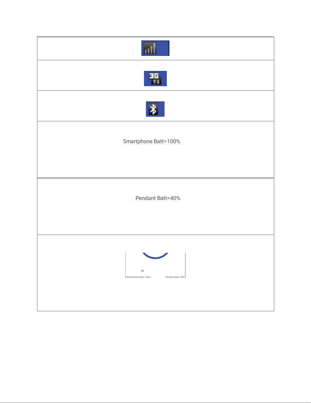
The Handset Battery Strength Indicator
This is the Handset Battery Strength Indicator in percentages. This is located in the lower left
corner of the Handset screen once Bluetooth communication has been set up. In this
example, the Handset battery strength is 100 percent.
Pendant Battery Strength Indicator
This is the Pendant Battery Strength Indicator in percentages. This is located in the lower
right corner of the Handset screen once Bluetooth communication has been set up. In this
example, the Pendant battery strength is 40 percent.
The Bluetooth Communication Indicator
This is the Bluetooth communication Indicator. Once Procedure Setup has been completed
and communication with the Pendant has been established, ' BT' will appear in the bottom
left side of the Handset screen.
USER MANUAL - UTM0000701-05E
15
| APRIL 4, 2019
Page 16
Have a question or need assistance?
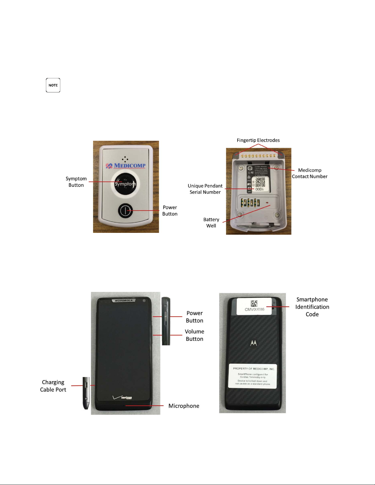
Below is a graphical overview of the TelePatch System. Detailed description of icons, buttons,
KEY DESCRIPTIONS PROVIDED BELOW ARE FOR USE WITH THE TELEPATCH APPLICATION
Front of Universal Pendant Back of Universal Pendant
Front of TelePatch Handset Back of TelePatch Handset
TelePatch™ Cardiac Monitor PM750
Call Medicomp’s Patient Support: 877-996-5553
and screen indicators are in previous section.
ONLY. KEY DESCRIPTIONS ARE NOT INTENDED FOR NORMAL CELLULAR PHONE USAGE.
Universal Pendant
Motorola Handset
USER MANUAL - UTM0000701-05E
16
| APRIL 4, 2019
Page 17
Have a question or need assistance?
Front of TelePatch Handset Back of TelePatch Handset
PENDANT AND Handset PICTURED ARE NOT ACTUAL SIZE.
TELEPATCH CARDIAC MONITOR DESCRIPTION
Below is an overview of the Universal Pendant, which is part of the TelePatch Cardiac Monitor
TelePatch™ Cardiac Monitor PM750
Call Medicomp’s Patient Support: 877-996-5553
LG Handset
Universal Pendant
Description
System. The Universal Pendant is very light-weight. It is a light gray, pager-sized ECG data
collecting Pendant.
USER MANUAL - UTM0000701-05E
17
| APRIL 4, 2019
Page 18
Have a question or need assistance?
TelePatch™ Cardiac Monitor PM750
2
099
Call Medicomp’s Patient Support: 877-996-5553
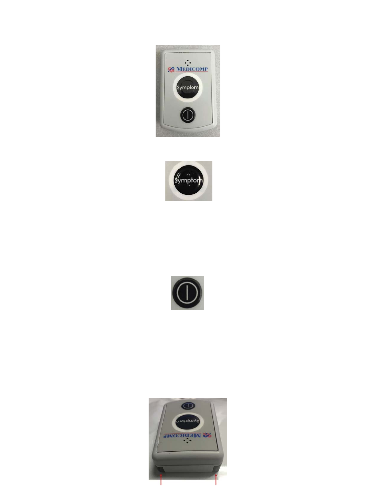
The Pendant SYMPTOM Button
The Universal Pendant has a Symptom* button which is located in the center of the face of the
Pendant. (*Symptoms can also be initiated on the Handset screen). The Symptom button has
two raised bars so it can be distinguished from power button by touch.
The Pendant POWER Button
The Pendant POWER button is located on the face of the Pendant, below the Symptom button.
Fingertip Electrode Accessory
The fingertip electrode is built into the Universal Pendant. Fingertip electrodes are used when
the patient cannot tolerate wearing the Electrode Patch or individual electrode patches.
USER MANUAL - UTM0000701-05E
| APRIL 4, 2019
18
Page 19
Have a question or need assistance?
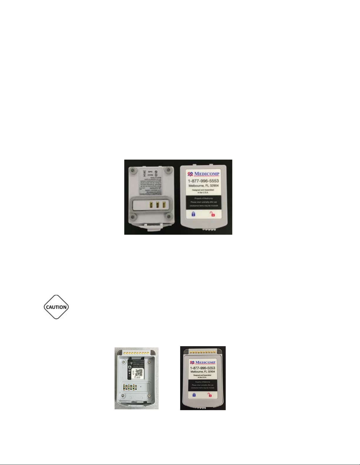
TelePatch Battery
Bottom and top views of the TelePatch lithium ion battery
TelePatch™ Cardiac Monitor PM750
Call Medicomp’s Patient Support: 877-996-5553
Fingertip electrode procedures should be performed only after consulting your physician.
Detailed directions about fingertip electrode procedures begin on page 49.
Universal Pendant
operates on a rechargeable, lithium ion battery. The battery locks into the
battery well of the back of the Universal Pendant.
THE RECHARGEABLE BATTERY PROVIDED WITH THE TELEPATCH SYSTEM IS NOT TO BE
DISCARDED IN HOUSEHOLD WASTE. IF A BATTERY GETS DAMAGED CONTACT MEDICOMP, INC.:
877-996-5553.
USER MANUAL - UTM0000701-05E
19
| APRIL 4, 2019
Page 20
Have a question or need assistance?
Battery Well Battery properly inserted in Battery Well
TelePatch Handset Description
Below is an overview of the TelePatch Handset, which is part of the TelePatch System.
TelePatch™ Cardiac Monitor PM750
Call Medicomp’s Patient Support: 877-996-5553
Detailed directions to change and charge the battery properly are found on page 25 or page 68.
IT IS VERY IMPORTANT TO TURN THE PENDANT OFF BEFORE CHANGING BATTERY,
OTHERWISE DATA MAY BE LOST. THE POWER BUTTON IS LOCATED ON THE FRONT FACE OF THE
PENDANT BELOW THE SYMPTOM BUTTON.
Motorola Handset
USER MANUAL - UTM0000701-05E
20
| APRIL 4, 2019
Page 21
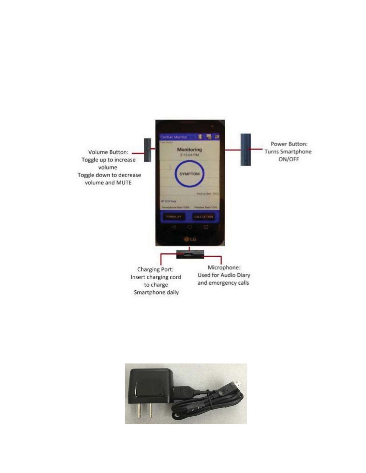
Have a question or need assistance?
Accessories to the TelePatch System
TelePatch™ Cardiac Monitor PM750
Call Medicomp’s Patient Support: 877-996-5553
LG Handset
USER MANUAL - UTM0000701-05E
21
| APRIL 4, 2019
Page 22
Have a question or need assistance?
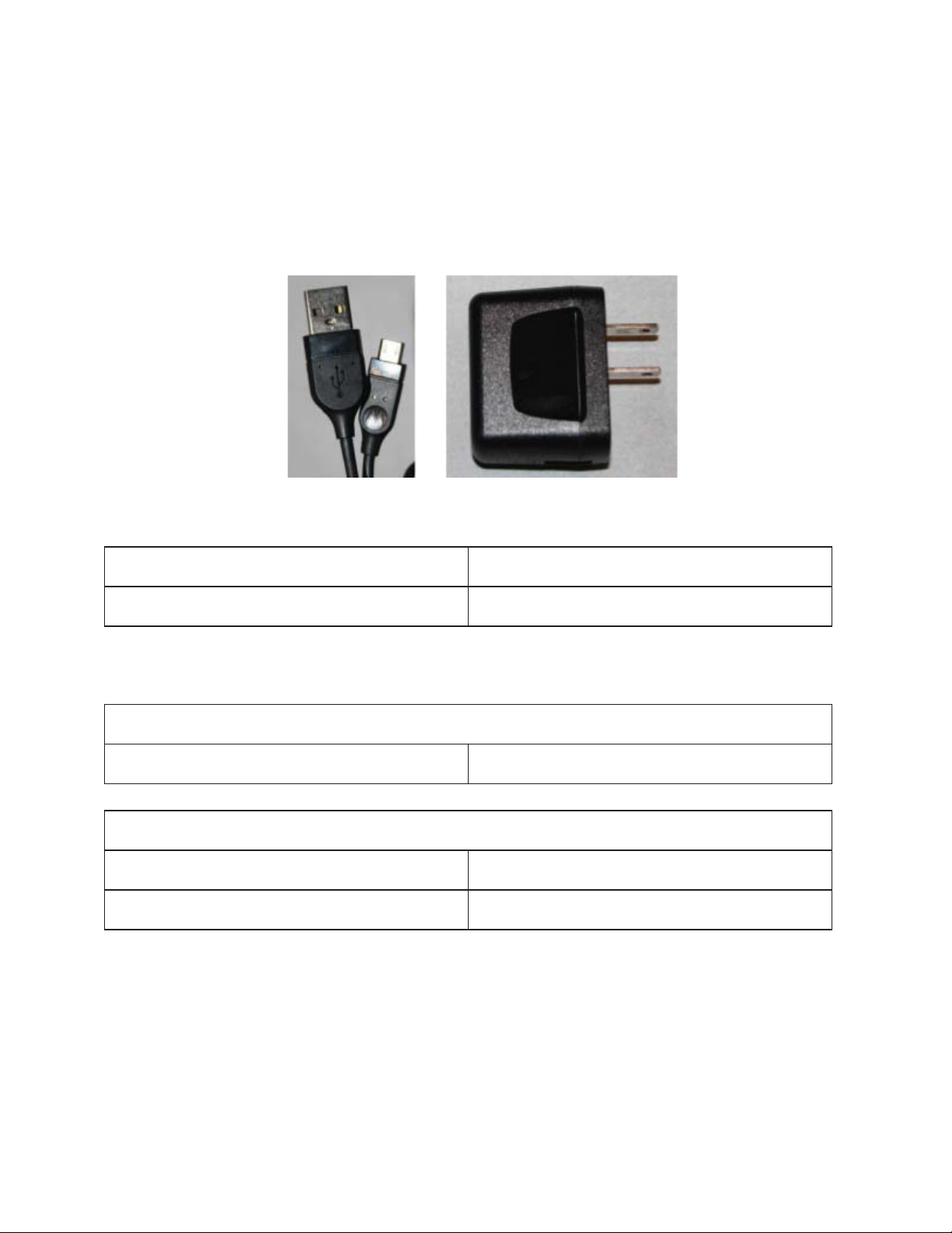
TelePatch Charger Cord
The TelePatch Charger Cord is compliant for use with the Handset and the Battery Charger.
Both are components of the TelePatch System. The Charger Cord is a two piece device:
SKN6430A / S13239-0403532
SPN5504A / S004ASU0510085
The TelePatch Charger Cord will replenish battery power when the Handset power or Pendant
TelePatch™ Cardiac Monitor PM750
Call Medicomp’s Patient Support: 877-996-5553
MicroUSB Cable AC Power Supply
MicroUSB Cable
AC Power Supply
Details pertaining to pertinent electrical specifications are provided below.
MicroUSB cable
Connector type Micro-USB
AC Power Supply
INPUT 100-240V~ 50/60Hz 0.2A
OUTPUT 5.1V=850mA 13262-1109957
Battery is depleted. When the Handset is turned on, the Handset battery indicator lets users
know when the battery life of the Handset and the Pendants Lithium Ion Battery are depleting.
Icons are displayed on the screen of the Handset.
USER MANUAL - UTM0000701-05E
22
| APRIL 4, 2019
Page 23
Have a question or need assistance?
(2) lithium ion batteries in the TelePatch Kit, so the procedure will not be interrupted.
and the Power Supply) when the TelePatch Kit is received, insert the USB connector into the
TelePatch™ Cardiac Monitor PM750
Call Medicomp’s Patient Support: 877-996-5553
For optimal performance from the Handset, it is recommended to plug the charger cord into
the Handset overnight until the Handset is fully charged. Instructions on charging the Handset
are on page 22 of this User Manual.
Universal Pendant
Batteries will need to charge every seven (7) days on average. There are two
Instructions about how to charge the Pendant Battery can be found in the charging the
Batteries section of this User Manual.
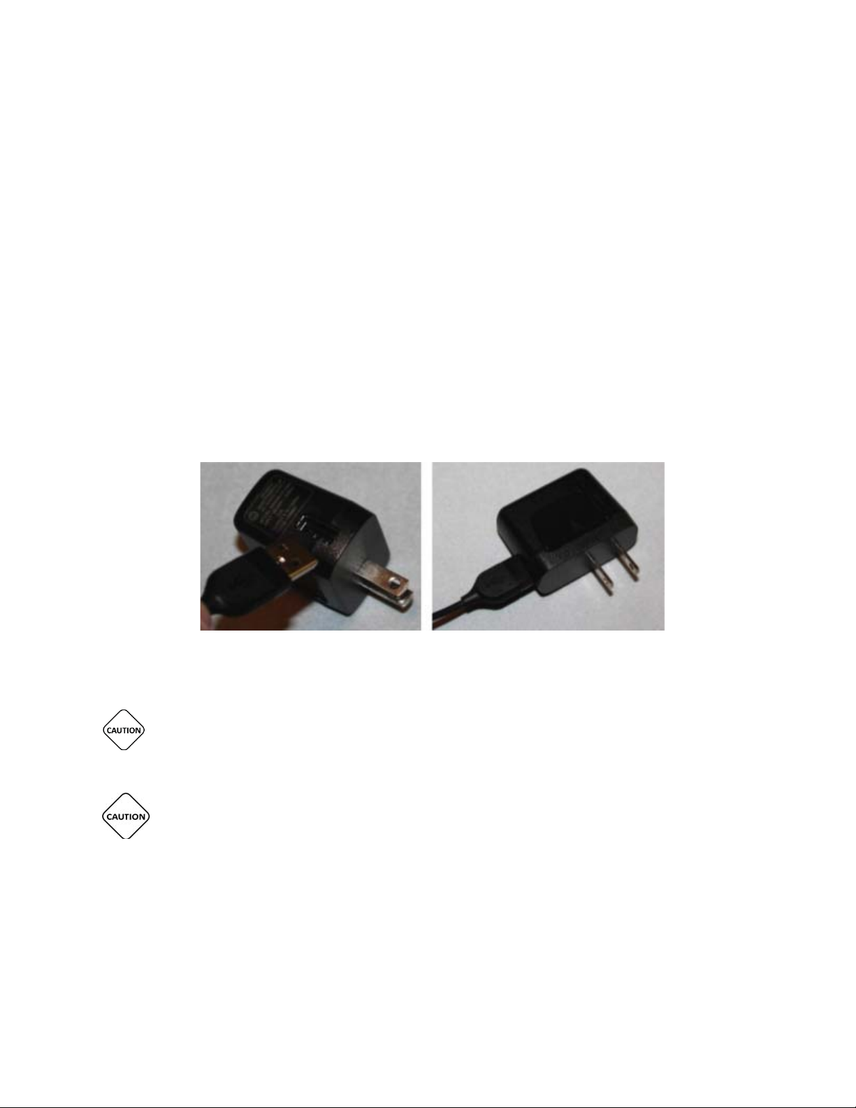
How to attach USB Cable to AC Power Supply block:
Should the Charger Cord come apart or if the Charger Cord is in two pieces (the MicroUSB cable
port on the power supply. Keep the two pieces connected for the duration of the procedure.
Handset AND BATTERY CHARGER ARE POWERED BY THE CHARGER CORD ONCE
CHARGER CORD IS PLUGGED IN TO Handset OR BATTERY CHARGER AND THEN A WALL
OUTLET.
CHARGER CORD MUST NOT BE OBSTRUCTED BY FURNITURE OR LARGE OBJECTS AND
REMAIN ACCESSIBLE TO DISCONNECT FROM WALL OUTLET EASILY, AS NEEDED.
USER MANUAL - UTM0000701-05E
23
| APRIL 4, 2019
Page 24
Have a question or need assistance?
TelePatch™ Cardiac Monitor PM750
Call Medicomp’s Patient Support: 877-996-5553
Connecting Charger Cord: Handset
Motorola Handset
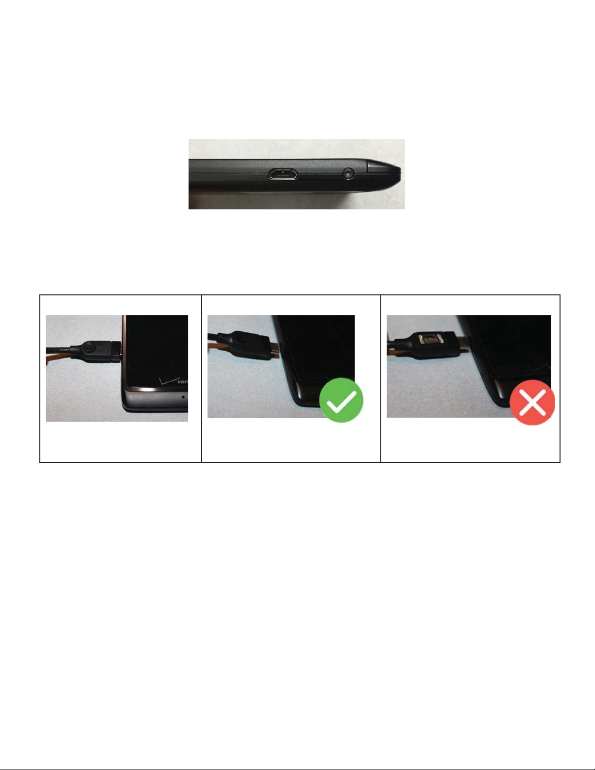
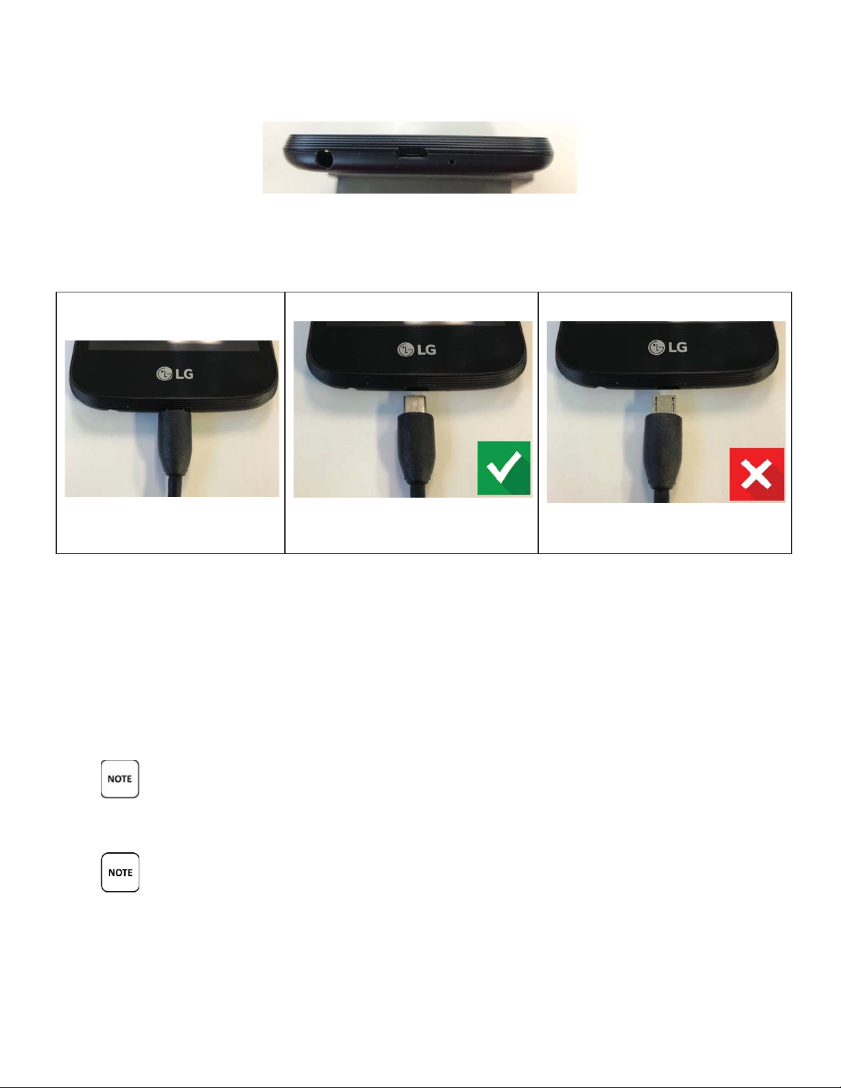
The port for the Motorola Charger Cord is located on the left side of the Handset near the
bottom
Charger properly inserted
Correct direction of charger head
Incorrect direction of charger head
USER MANUAL - UTM0000701-05E
24
| APRIL 4, 2019
Page 25
Have a question or need assistance?
TelePatch™ Cardiac Monitor PM750
Call Medicomp’s Patient Support: 877-996-5553
LG Handset
The port for the LG Charger Cord is located on the bottom side of the Handset.
Charger properly inserted
Correct direction of charger head
Incorrect direction of charger head
Connecting the Charger Cord to the Handset:
Take the end of the Charger Cord and insert it into the lower left side or bottom of the Handset
as displayed in the graphic above according to the handset manufacturer. The side of the
Charger Cord plug-in with the engaging teeth facing down is the correct way to insert the
Charger Cord into the Handset.
WHEN CHARGING IS COMPLETE, UNPLUG THE CHARGER CORD FROM THE POWER
OUTLET AND THE Handset.
MAKE SURE WALL OUTLET IS NOT CONTROLLED BY A LIGHT SWITCH.
USER MANUAL - UTM0000701-05E
25
| APRIL 4, 2019
Page 26
Have a question or need assistance?
TelePatch Battery Charger
TelePatch rechargeable batteries have an approximate seven (7) day life before needing to be
recharged. The TelePatch Kit has two (2) batteries, a Battery Charger and a Charger Cable (also
Using the Charger Cord with the TelePatch Battery Charger
TelePatch™ Cardiac Monitor PM750
Call Medicomp’s Patient Support: 877-996-5553
Handset IS POWERED BY THE CHARGER CORD ONCE CHARGER CORD IS PLUGGED IN TO
BOTH Handset AND WALL OUTLET.
CHARGER CORD MUST NOT BE OBSTRUCTED BY FURNITURE OR LARGE OBJECTS AND
REMAIN ACCESSIBLE TO DISCONNECT FROM WALL OUTLET EASILY, AS NEEDED.
UNPLUG THE CHARGER CORD FROM THE Handset BEFORE PLACING Handset IN
POCKET OR PURSE/BRIEFCASE. DO NOT WEAR THE H
ANDSET WHILE THE CHARGER IS
ATTACHED TO THE HANDSET.
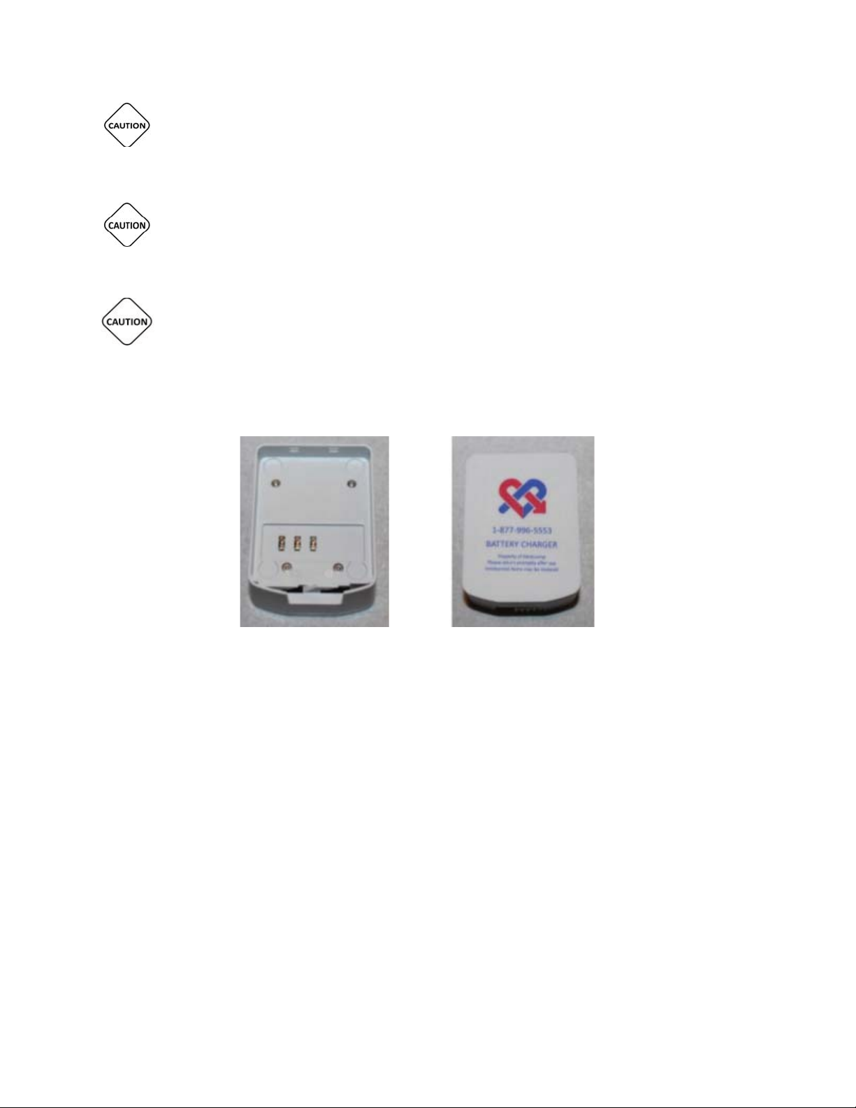
Battery Charger – Top Battery Charger - Bottom
used to charge the Handset).
Universal Pendant
batteries need to be changed when the Pendant indicates the battery is low
on power: the orange LED will blink continuously on the face of the Pendant, and the Pendant
will chirp every 4 minutes. The battery level can also be seen on the Handset screen.
USER MANUAL - UTM0000701-05E
26
| APRIL 4, 2019
Page 27
Have a question or need assistance?
The TelePatch Battery Charger will replenish battery power when lithium ion battery power is
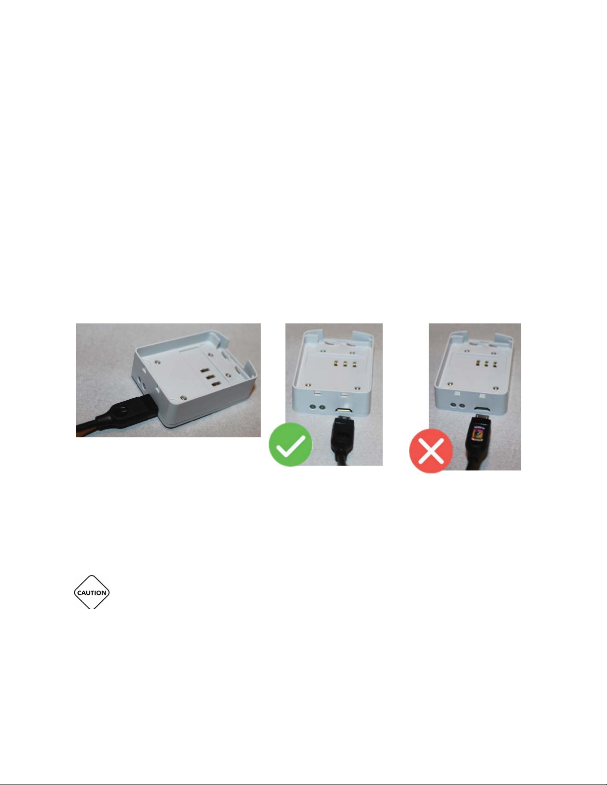
Connecting Charger Cord To Battery Charger:
Charger Cord head
Charger Cord head
TelePatch™ Cardiac Monitor PM750
Call Medicomp’s Patient Support: 877-996-5553
depleted. The same Charger Cord used to charge the Handset is used to power the Battery
Charger.
For optimal performance from the Battery Charger, it is recommended to plug the Charger Cord
into the Battery Charger and a wall outlet until the battery is fully charged. The indicator light
on the flat end of the charger, next to the Charger Cord outlet, is flashing orange while
charging, and steady green when fully charged. The Battery Charger will stop charging the
battery once fully charged.
● Place the Battery Charger on a flat, dry surface, near a wall outlet
● Plug Charger Cord into the corresponding outlet on the Battery Charger
● Plug the Charger Cord into the wall outlet
Charger Cord properly inserted into
Battery Charger
Correct direction of
Incorrect direction of
Charging a Battery in the Battery Charger:
THIS PRODUCT UTILIZES A RECHARGEABLE LITHIUM-ION BATTERY PACK. TO ENSURE
SAFE CHARGING AND MAXIMUM PERFORMANCE OVER THE LIFE OF THE PRODUCT ALWAYS
USE THE MEDICOMP PROVIDED CHARGER. DO NOT ATTEMPT TO CHARGE THE BATTERY ON
ANOTHER MANUFACTURER’S CHARGER.
USER MANUAL - UTM0000701-05E
27
| APRIL 4, 2019
Page 28

Have a question or need assistance?
Place a Battery from the TelePatch Kit into the Battery Charger, with the Medicomp
TelePatch™ Cardiac Monitor PM750
itototor PMPMPMPMPM0
0707011-0-0-005E5E
AA4
,
,
,
000
Call Medicomp’s Patient Support: 877-996-5553
●
label facing up and the two small tabs into the notches.
● Slide the latch at the back of the Battery to the left, securing the battery in place. The
Battery is locked in place when the latch is below the BLUE lock icon.
Battery IS NOT locked in the charger Battery IS correctly locked into charger
● A light at the end of the Battery Charger, next to the Charger Cord, will turn green when
the battery is fully charged.
USER MANUAL - UTM0000701-05E
28
| APRIL 4, 2019
9
Page 29

Have a question or need assistance?
TelePatch Electrode Patch
TelePatch™ Cardiac Monitor PM750
Call Medicomp’s Patient Support: 877-996-5553
Flashing Orange Light: Battery is charging Green Light: Battery is charged
MAKE SURE WALL OUTLET IS NOT CONTROLLED BY A LIGHT SWITCH.
BATTERY CHARGER IS POWERED BY THE CHARGER CORD ONCE CHARGER CORD IS
PLUGGED IN TO BOTH BATTERY CHARGER AND WALL OUTLET.
CHARGER CORD MUST NOT BE OBSTRUCTED BY FURNITURE OR LARGE OBJECTS AND
REMAIN ACCESSIBLE TO DISCONNECT FROM WALL OUTLET EASILY, AS NEEDED.
THIS PRODUCT UTILIZES A RECHARGEABLE LITHIUM-ION BATTERY PACK. ALL
BATTERIES WILL SLOWLY DISCHARGE OVER TIME EVEN IF THEY AREN’T USED. TO
ENSURE OPTIMAL PERFORMANCE AND LIFETIME OF THE BATTERY PACK, PLEASE
FULLY CHARGE THE BATTERY AT LEAST ONCE EVERY 6 MONTHS REGARDLESS OF USE. IT IS
FURTHER RECOMMENDED THAT IF THE BATTERY HASN’T BEEN CHARGED MORE RECENTLY
THAN A MONTH AGO THAT IT BE FULLY CHARGED PRIOR TO THE START OF A PATIENT
PROCEDURE.
DO NOT STORE BATTERIES IN THE BATTERY CHARGER.
USER MANUAL - UTM0000701-05E
29
| APRIL 4, 2019
Page 30
Have a question or need assistance?
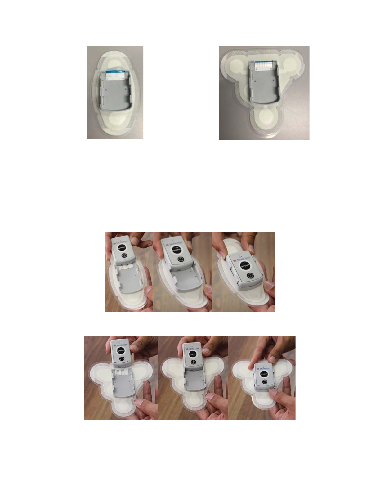
Single Channel Electrode Patch with Cradle
Dual Channel Electrode Patch with Cradle
The Universal Pendant slides into the cradle on the Electrode Patch.
TelePatch™ Cardiac Monitor PM750
Call Medicomp’s Patient Support: 877-996-5553
Placing Pendant into Electrode Patch cradle:
● Slide Pendant into cradle with lock facing down into cradle.
● The Pendant is correctly placed when it clicks into cradle.
USER MANUAL - UTM0000701-05E
30
| APRIL 4, 2019
Single Channel Electrode Patch
Dual Channel Electrode Patch
Page 31
Have a question or need assistance?
TelePatch™ Cardiac Monitor PM750
USER MANUAL - UTM0000701-05E | APRIL 4, 2019
Call Medicomp’s Patient Support: 877-996-5553
● Single Channel Electrode Patch supports modified lead II with reference right leg drive.
● Dual Channel Electrode Patch supports Channel A modified lead II, Channel B modified
III and a reference electrode.
THE TELEPATCH ELECTRODE PATCH IS A SINGLE USE ITEM. ONCE THE ELECTRODE PATCH
IS REMOVED FROM THE SKIN IT SHOULD BE DISCARDED AS HOUSEHOLD WASTE.
PLEASE DO NOT DISCARD THE Universal Pendant. MAKE SURE TO REMOVE THE
Universal Pendant FROM THE CRADLE BEFORE DISCARDING THE ELECTRODE PATCH. THE
PENDANT IS TO BE INSERTED IN THE CRADLE OF A FRESH ELECTRODE PATCH TO CONTINUE
PROCEDURE.
Description of Patch and Patch Packaging
Electrode Patch
Description Medical sensor electrode, Foam, 1.5”
teardrop shape, wet gel
Gel Wet Gel 7% KCL
Gel Sponge Polyurethane (reticulated foam)
Substrate Polyester printed with black ink
Foam Polyethylene foam with acrylic adhesive
Conductive Ink Ag/AgCl
Insulator Blue UV Dielectric
Release Liner Polystyrene (HIPS) with silicone release
Connector 5 Pin Housing
31
Packaging
Page 32

Have a question or need assistance?
TelePatch Electrode Patch Procedure
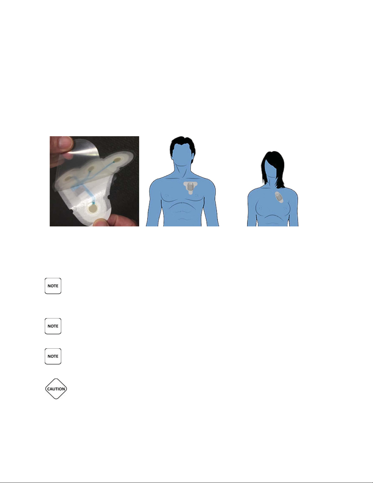
TelePatch Cardiac Monitor procedure with the Electrode Patch. Follow the skin preparation
Patch Placement for the TelePatch Procedure
TelePatch™ Cardiac Monitor PM750
Call Medicomp’s Patient Support: 877-996-5553
Pouch
Material 25# Paper/7.2#LOPE/.0003 Foil/14# LDPE
(minimum)
Dimensions 7”x11”
Pouch Contents
Printed Circuit Sensor
STANDARD PROCEDURE SET-UP
Patient Preparation
This section contains step-by-step instructions that describe how to prepare patient for a
sequence as closely as possible. This will greatly enhance the ECG signal quality and optimize
analysis.
Step 1 - Identify Electrode Patch Site
For TelePatch Wireless Single Channel
1. LEFT side of chest.
2. Top of patch (Medicomp logo right-side up) near top of breast bone.
3. Bottom of patch angled toward left nipple at a 45- to 60- degree angle.
For TelePatch Wireless Dual Channel:
1. LEFT side of chest.
2. Flay edge parallel to and one inch below collar bone
3. About one inch left of breast bone.
Refer to the figure below for proper patch placement:
USER MANUAL - UTM0000701-05E
32
| APRIL 4, 2019
Page 33

Have a question or need assistance?
Step 2 - Prepare the Skin
TelePatch™ Cardiac Monitor PM750
Call Medicomp’s Patient Support: 877-996-5553
Dual Channel and Single Channel Electrode Patch Placement
Because the Electrode Patch will be worn for up to seven (7) days, proper skin preparation is
important for the procedure. Good skin preparation means better ECG signal traces that, in
turn, are easier for the doctor to review and evaluate. In order to obtain the best ECG
recording, the following procedure is recommended for initial hookup:
1. Whenever possible, be in an upright sitting position. This may be useful if any setup
problems occur that concern the signal voltage.
2. Following the placement diagram, select sites that are flat. Avoid skin folds or creases,
irritated skin or scar tissue, and highly muscular areas.
3. If necessary, shave an area at the patch site slightly larger than the size of the Electrode
Patch.
4. If powder, lotion, sunblock, etc. has been applied to the chest or if skin is excessively
oily, wash site with plain soap and water. Do not use a soap that contains lotion or oil.
5. Skin-prep pads (found in alcohol prep-pad type packaging) can be used to clean and
prepare skin for initial application.
The above skin prep procedure is only required at the beginning of the procedure, during
Handset initialization. Users will not be required to perform this type of preparation each time
they apply a new Electrode Patch. It is best for users to have freshly showered with plain soap
each time they apply new Electrode Patches (about every 7 days):
USER MANUAL - UTM0000701-05E
33
| APRIL 4, 2019
Page 34
Have a question or need assistance?
Applying TelePatch Patch:
TelePatch™ Cardiac Monitor PM750
Call Medicomp’s Patient Support: 877-996-5553
● If patch has connectivity issues the skin can be lightly abraded at each electrode site
with a rough washcloth, or an abrasive pad.
Step 3 - Electrode Patch Application
● Prepare skin, as shown in Step 2.
● When ready to position Electrode Patch on skin, remove backing from Electrode Patch,
apply to chest, using placement in the illustration. This can be done before inserting
Pendant in the cradle or after.
● Press Electrode Patch firmly onto skin with fingers once correctly positioned on the left
side of chest (Below collarbone).
● Once it is firmly adhered to skin peel remaining white tabs on the patch so the whole
surface of the patch is adhered to skin.
THE MEDICOMP ECG ELECTRODE PATCH IS SINGLE USE, NON-STERILE, AND DISPOSABLE
AND IS TO BE USED ON INTACT (UNINJURED) SKIN.
PRODUCT SHELF LIFE IN INTACT, ORIGINALLY SEALED PACKAGING IS 12 MONTHS.
ALLOW 15 MINUTES FOR SKIN TO ABSORB THE ELECTRODE GEL, WHICH MAY HELP
PROCEDURE INITIALIZATION ERRORS FROM OCCURRING.
CONDUCTIVE PARTS OF ELECTRODES AND ASSOCIATED CONNECTORS FOR TYPE BF OR
CF APPLIED PARTS, INCLUDING NEUTRAL ELECTRODE, SHOULD NOT CONTACT OTHER
CONDUCTIVE PARTS, INCLUDING EARTH.
USER MANUAL - UTM0000701-05E
34
| APRIL 4, 2019
Page 35
Have a question or need assistance?
Remove the Pendant from the TelePatch Kit.
TelePatch™ Cardiac Monitor PM750
c cMoMoMoMMMMitototototototootr rrPMMPMPPPPPPPM5000TTM0MMMM000070700001011-0-0-00
5
AAA4444
4
,
000099
Call Medicomp’s Patient Support: 877-996-5553
Wearing TelePatch:
● The Electrode Patch should stay in position for up to seven (7) days.
● The cradle on Electrode Patch holds the Pendant.
● Leave the Electrode Patch in place until it no longer remains adhered or as ordered by
physician.
● The Electrode Patch with the Universal Pendant
in the cradle can be worn in shower
during procedure, pat dry with a towel once shower is complete.
● Do not go swimming while wearing Electrode Patch or Pendant during procedure.
● The Electrode Patch should be disposed of when changed for a fresh Electrode Patch or
at the completion of the procedure. For additional patches for your procedure contact
Medicomp Patient Care: 877-996-5553
DO NOT WEAR ELECTRODE PATCH OR Universal Pendant
SWIMMING OR SUBMERGED
IN WATER DURING PROCEDURE.
THE PENDANT AND BATTERY ARE NOT DISPOSABLE. THE PENDANT SHOULD BE
REMOVED FROM THE CRADLE ON THE ELECTRODE PATCH AND PLACED IN THE CRADLE OF THE
FRESH ELECTRODE PATCH.
THE TELEPATCH ELECTRODE PATCH IS A SINGLE USE ITEM. ONCE THE ELECTRODE PATCH
IS REMOVED FROM THE SKIN IT SHOULD BE DISCARDED AS HOUSEHOLD WASTE.
Step 4 - Turn on Pendant and Connect
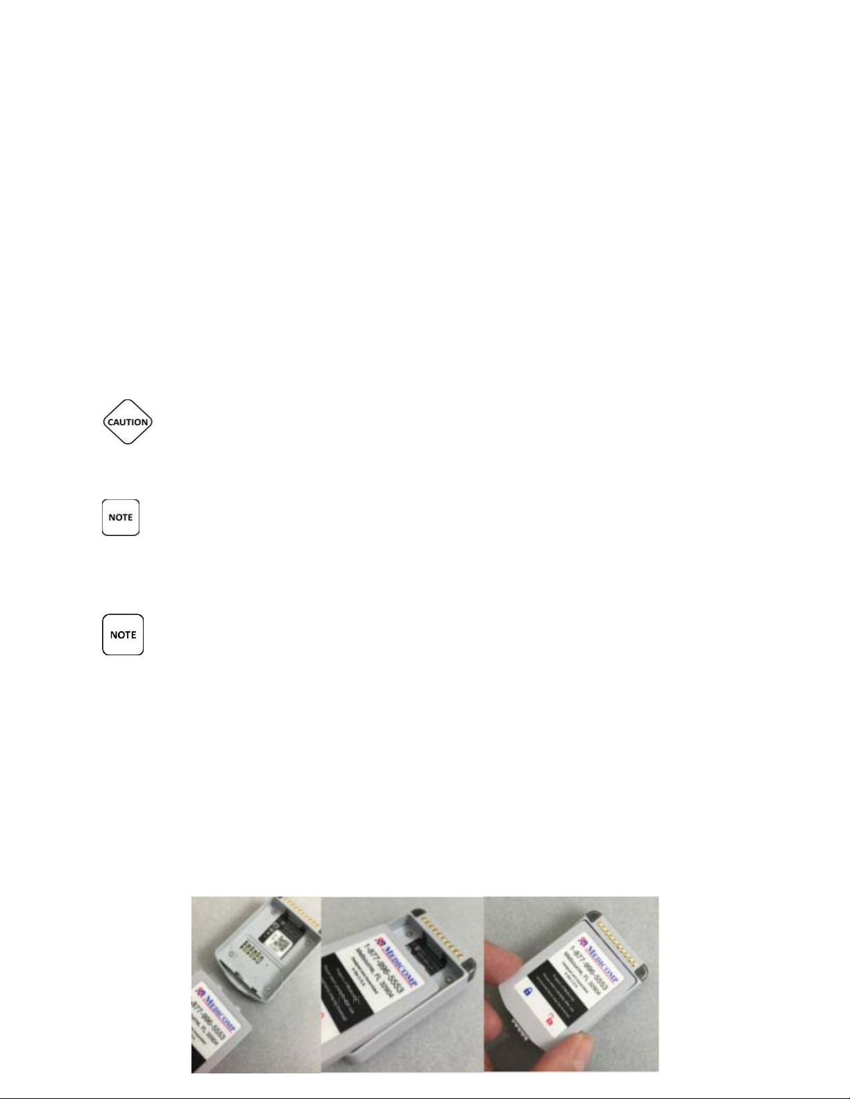
Insert a Battery into the Pendant:
●
● Hold Pendant face down in hand or on a flat surface. There is a well for Battery to be
inserted
● Insert the Battery into the opening, with the Medicomp label facing up and the two
small tabs into the notches, as pictured.
USER MANUAL - UTM0000701-05E
35
| APRIL 4, 2019
Page 36
Have a question or need assistance?
TelePatch™ Cardiac Monitor PM750
AA4
,
,
099
Call Medicomp’s Patient Support: 877-996-5553
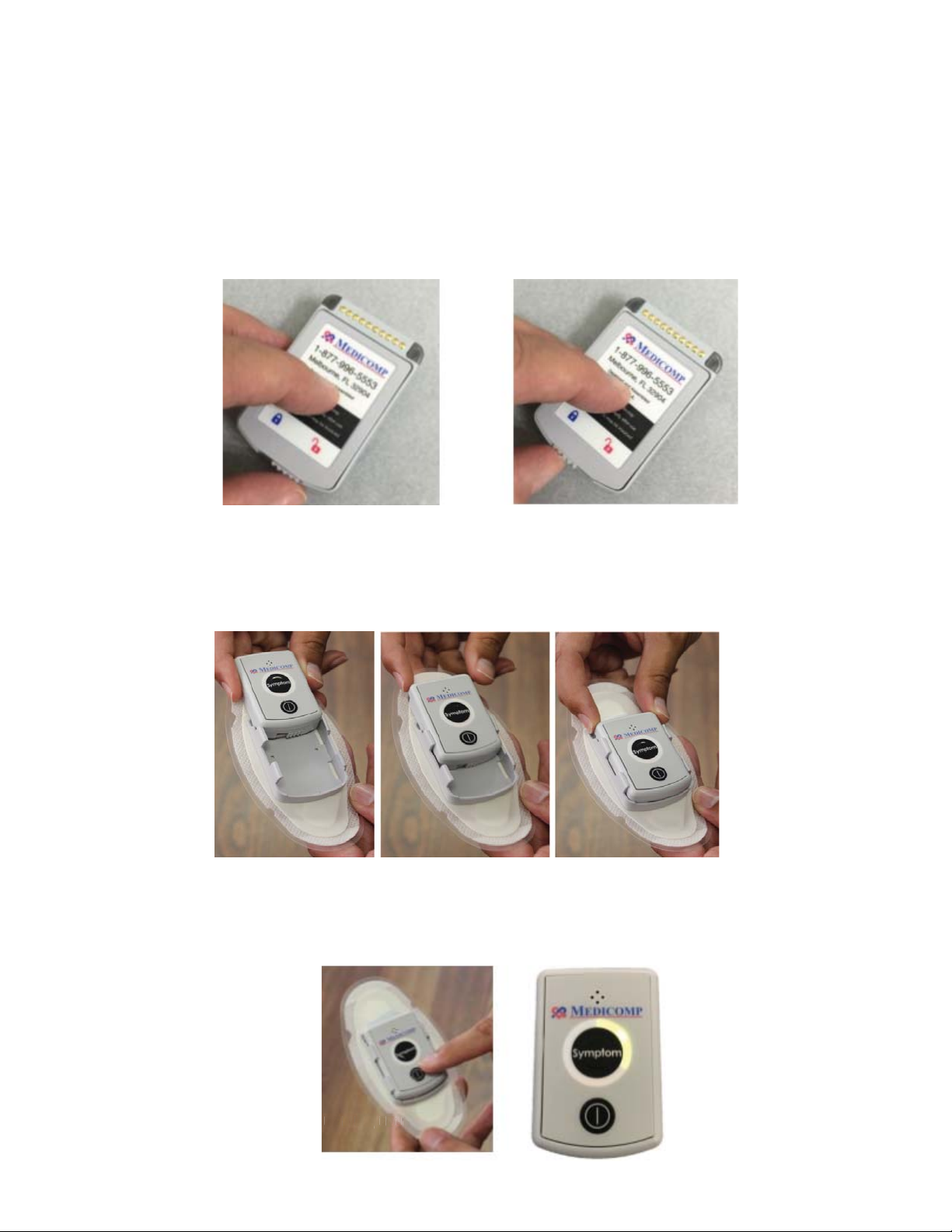
● Slide the latch at the back of the Battery to the left, securing the Battery in place
Battery is NOT secure in Pendant – Unlocked Battery IS secure in Pendant - Locked
● Turn the Pendant over, slide the Pendant into the Electrode Patch Cradle with the lock
facing down into the cradle.
● The Pendant is correctly placed when it clicks into the Electrode Patch Cradle.
Turn the Pendant on:
● Press and hold the power button on the face of the Pendant until the Pendant green
LED flashes.
USER MANUAL - UTM0000701-05E
| APRIL 4, 2019
36
Page 37

Have a question or need assistance?
For a Holter procedure: (24 hour to 96 hour)
For all other procedures: (7 day to 30 day)
During the TelePatch Procedure:
A physician will determine the duration of the TelePatch procedure.
All regular activities can be enjoyed during a TelePatch procedure.
IMPORTANT NOTE: If setting up a 24 hour – 96 hour Holter procedure, the procedure set-up is
TelePatch™ Cardiac Monitor PM750
USER MANUAL - UTM0000701-05E | APRIL 4, 2019
Call Medicomp’s Patient Support: 877-996-5553
●
o Press the Symptom button three (3) times.
●
o The Pendant will initiate on its own.
o If Pendant does not turn on its own, press Power button to turn on pendant.
● Wear the Electrode Patch and Universal Pendant
●
● The Electrode Patch will stay in position for up to seven (7) days.
● The Pendant should always be in the Electrode Patch Cradle.
● Universal Pendant
and Electrode Patch can be worn in the shower and during exercise.
all day and all night.
TURN THE PENDANT ON BEFORE TAPPING “START PROCEDURE” ON THE Handset AS THE
Handset WILL IMMEDIATELY LAUNCH A PROCESS THAT WILL START COMMUNICATION TO THE
PENDANT VIA BLUETOOTH TECHNOLOGY. IF THE PENDANT IS NOT TURNED ON AT THAT TIME,
THE Handset WILL NOT BE ABLE TO IDENTIFY THE PENDANT.
PENDANT BATTERY NEEDS TO BE CHANGED ABOUT EVERY SEVEN (7) DAYS.
IT IS VERY IMPORTANT TO TURN THE PENDANT OFF BEFORE CHANGING BATTERY,
OTHERWISE DATA MAY BE LOST. THE ON/OFF BUTTON IS LOCATED ON THE FACE OF THE
PENDANT.
THE PENDANT AND BATTERY ARE NOT DISPOSABLE. THE PENDANT SHOULD BE REMOVED
FROM THE CRADLE ON THE ELECTRODE PATCH AND PLACED IN THE CRADLE OF THE FRESH
ELECTRODE PATCH.
complete at this point. The Handset is not used with Holter procedures
37
.
Page 38
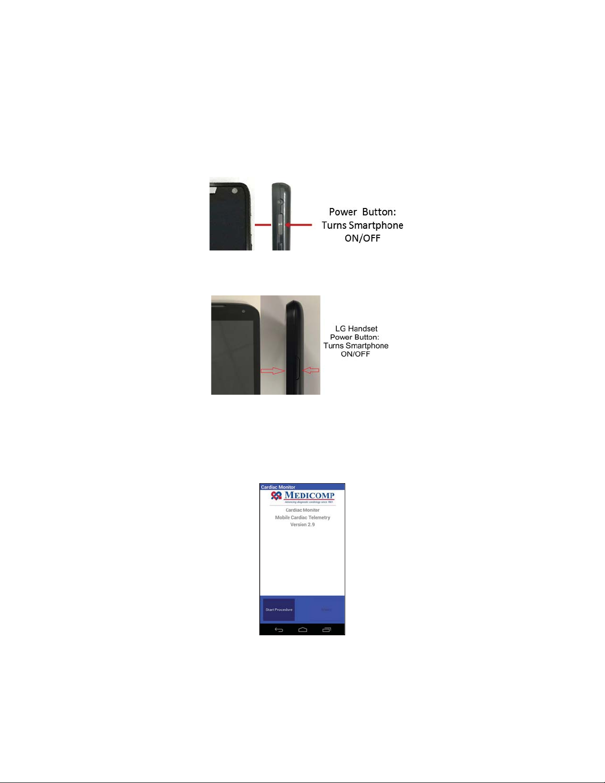
Have a question or need assistance?
Medicomp TelePatch Handset Main Screen
TelePatch™ Cardiac Monitor PM750
Call Medicomp’s Patient Support: 877-996-5553
Step 5 - Starting the Handset
Before using the Handset:
● Charge the Handset until it is fully powered. If it is not fully charged (low) a red LED will
flash in the upper left corner of the face of the Handset.
Motorola Handset
LG Handset
● Take the Handset and turn it on by pressing and holding the POWER button which is
located in the upper right side of the Handset.
● Wait for the Medicomp main screen to appear on the screen before continuing with
standard procedure setup.
● Tap “Start Procedure.”
USER MANUAL - UTM0000701-05E
38
| APRIL 4, 2019
Page 39
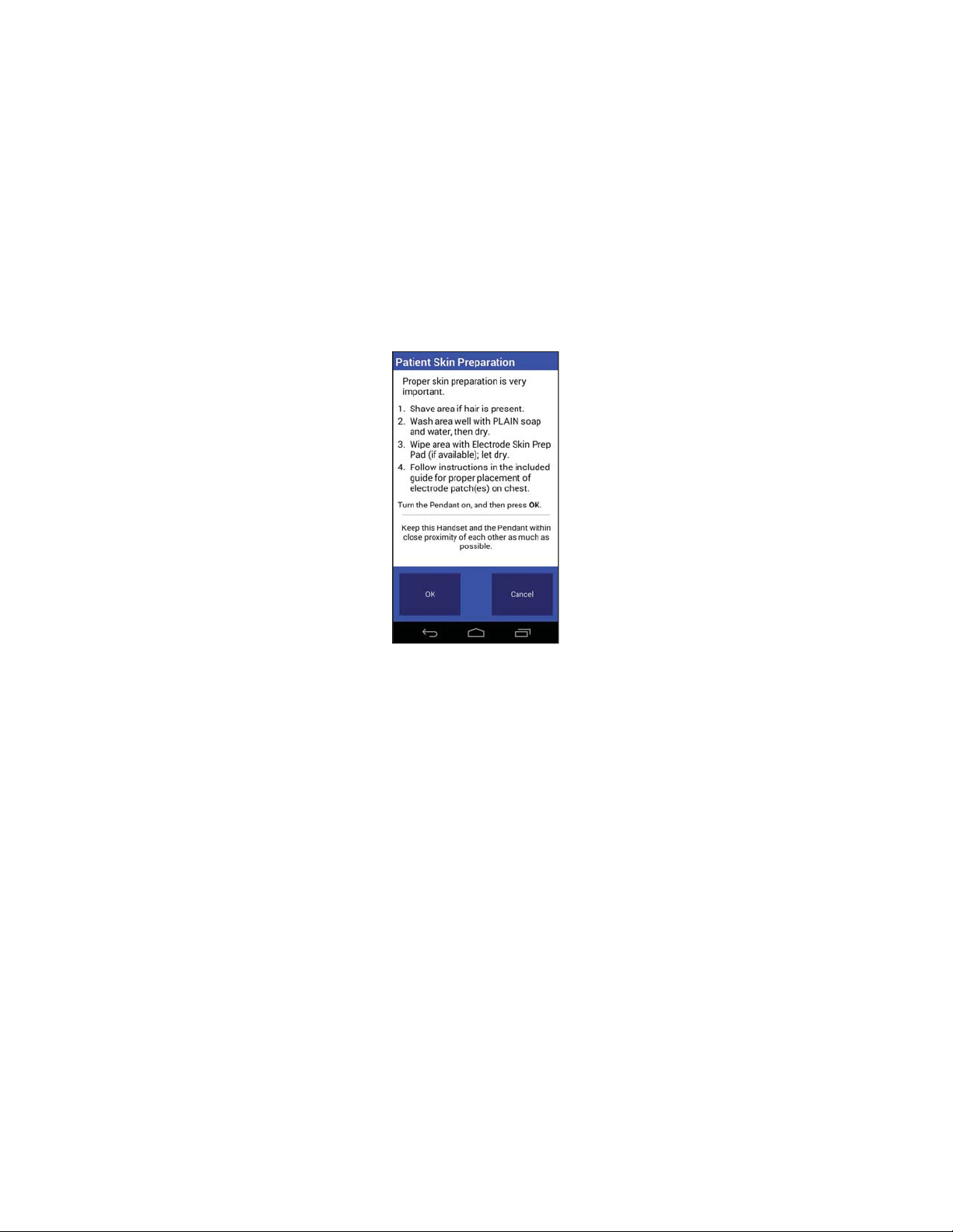
Have a question or need assistance?
with the TelePatch System. The steps are described below.
Medicomp TelePatch Handset
necessary procedure settings from the TelePatch System.
TelePatch™ Cardiac Monitor PM750
Call Medicomp’s Patient Support: 877-996-5553
Step 6 - Procedure Set Up
After identifying Electrode Patch site, preparing the skin, applying the Electrode Patch and,
turning on the Pendant, turning on the Handset, the patient is now ready for 'Procedure Setup'
After following the instructions on the patient preparation screen, which may have already
been completed, the next step is to select the correct settings before starting a procedure.
Patient Preparation Screen
● Tap “OK”
Step 7 - Procedure Settings
After following the instructions on the patient preparation screen, the next step is to select the
correct settings before starting a procedure. Follow the instructions below on how to select the
The Procedure Setup screen will display the default settings, which are:
Patient has Pacemaker = No
Protocol = Standard
Setup = Normal
USER MANUAL - UTM0000701-05E
39
| APRIL 4, 2019
Page 40

Have a question or need assistance?
Medicomp TelePatch Handset
TelePatch™ Cardiac Monitor PM750
Call Medicomp’s Patient Support: 877-996-5553
Procedure Set Up Screen
Choose “Accept Settings” or change settings from this screen.
To accept default settings:
● Tap “Accept Settings”.
OR to change settings:
● Tap the setting to be changed.
Pacemaker Settings
The following describes the steps and screens when 'Pacemaker' is selected as a setting. To
select a setting for pacemakers:
● Tap “No”.
● Tap option desired.
● If the patient desires to change more settings, then repeat the steps above for Protocol
and Setup.
● After all the correct settings have been chosen.
● Tap “Accept Settings”.
● If the 'Pacemaker' setting is selected, and if a paced beat was detected as typical, the
Handset displays a screen of the ECG during the procedure setup. Then it will display the
settings. Please select “Yes” to accept this step.
● After all the correct settings have been chosen.
● Tap “Accept Settings”
USER MANUAL - UTM0000701-05E
40
| APRIL 4, 2019
Page 41
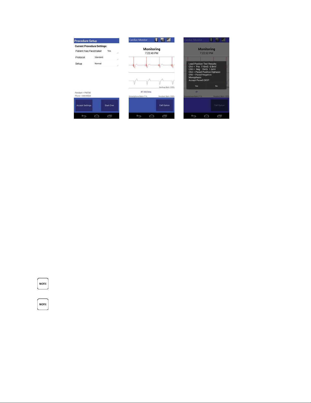
Have a question or need assistance?
THE TELEPATCH SYSTEM CAN BE USED FOR INFANTS WEIGHING LESS THAN 10KG.
TelePatch™ Cardiac Monitor PM750
Call Medicomp’s Patient Support: 877-996-5553
Pacemaker Setup Screens
● For additional standard procedure setup instructions, go to patient preparation.
Protocol Setting
'Protocol' has three (3) sub-options. More information pertaining to those options is provided
below:
● Standard - “Standard” is the default for adult users.
● Atrial Fib - Use “Atrial Fib” for users who have permanent Atrial Fibrillation.
● Pediatric - Use “Pediatric” for users under 16 years of age.
Users should check with child's Pediatrician to verify heart rate. The Pediatric protocol sets
Normal Sinus Rhythm at 80-150 bpm. To select a setting from protocol:
To apply 'Protocol' as a setting:
● Tap “Standard”
● Tap desired Protocol
● Press “Accept Settings”
● For additional standard procedure setup instructions, go to PATIENT PREPARATION.
“TEST”SHOULD NEVER BE SELECTED AS A SETTING WITHOUT THE SUPERVISION AND
GUIDANCE OF A MEDICOMP CARDIAC MONITORING CENTER (CMC) TECHNICIAN. CALL THE
CMC FOR GUIDANCE IN “TEST” MODE.
USER MANUAL - UTM0000701-05E
41
| APRIL 4, 2019
Page 42

Have a question or need assistance?
All TelePatch systems will be shipped in “Normal” mode. There is therefore, no need to instruct
Pediatric Protocol: this range is 80-150 bpm. Therefore, the TelePatch System would not
TelePatch™ Cardiac Monitor PM750
Call Medicomp’s Patient Support: 877-996-5553
Set Up
users on how to select the “Normal” mode. The following instructions describe the steps and
screens for selecting “Test” mode. To apply the “Test” mode:
• Tap “Normal”.
• Tap “Test” on drop down menu.
If there are additional settings changes desired, repeat the steps above
for Pacemaker and Protocol. After all the correct settings have been
chosen,
• Tap “Accept Settings”
An example of a test result screen for the Skin Prep is provided below.
Skin Prep Test Result
For additional standard procedure setup instructions, go to PATIENT PREPARATION.
If a mistake is made during the procedure setup process, the set up can Start Over.
“START OVER” WILL ERASE ALL PREVIOUS SETTING SELECTIONS IN ORDER TO START THE
ENTIRE PROCEDURE SETTINGS PROCESS FROM THE VERY BEGINNING.
Start Over:
• Tap “Start Over” button.
This will erase all previous setting selections in order to start the entire procedure settings
process over from the very beginning:
● Protocol: The protocol is an integral part of the auto capture capability. It may be
defined as a set of guidelines that the ECG analysis algorithm uses in identifying
clinically-significant events. For example, the normal heart rate in Standard protocol is
60-100 bpm.
●
trigger to generate recordings for heart-rate events of 140 bpm if the protocol had been
set to Pediatric, but would trigger if it had been set to Standard.
● For additional standard procedure setup instructions, go to PATIENT PREPARATION.
USER MANUAL - UTM0000701-05E
42
| APRIL 4, 2019
Page 43
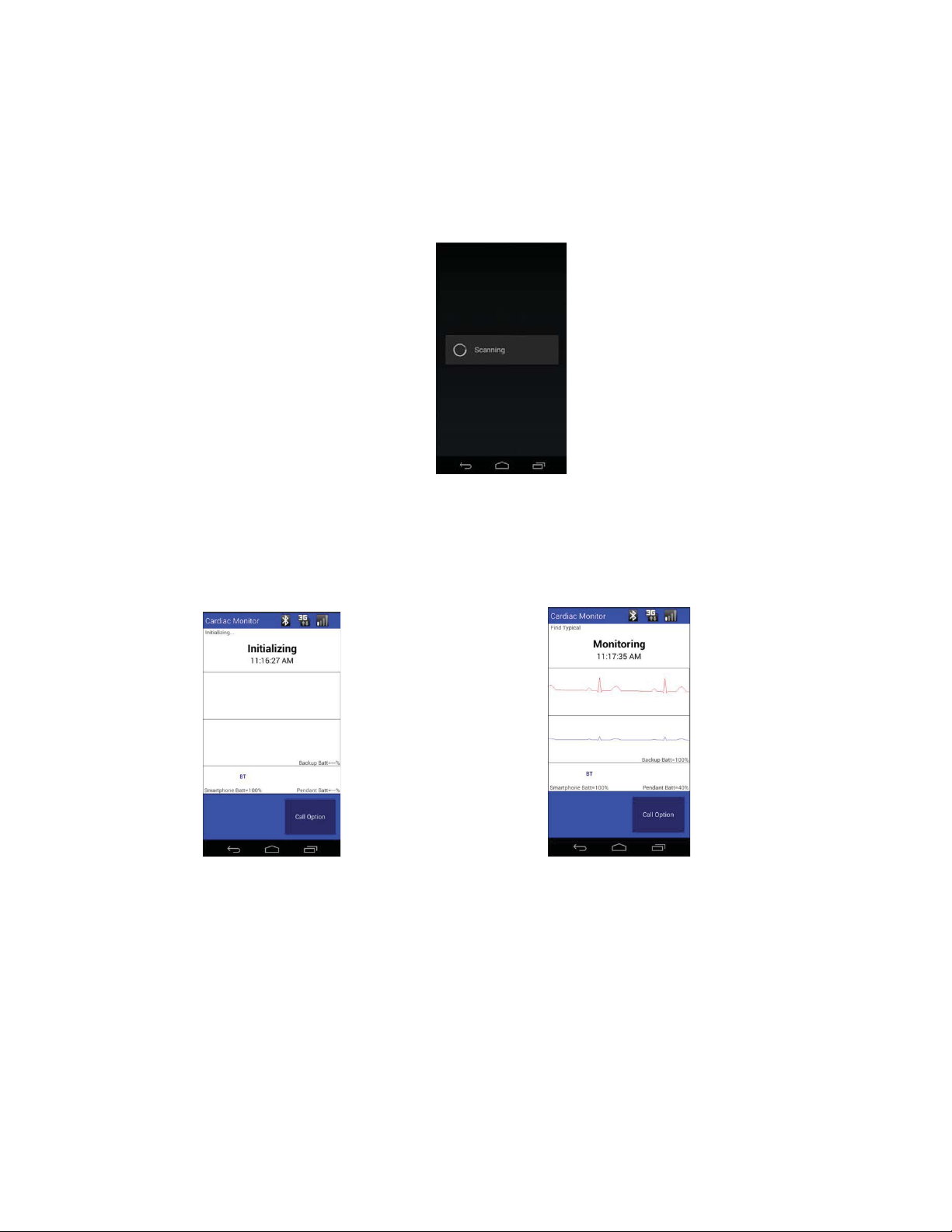
Have a question or need assistance?
Medicomp TelePatch Handset
Scanning for Universal Pendant
Medicomp TelePatch Handset
Medicomp TelePatch Handset
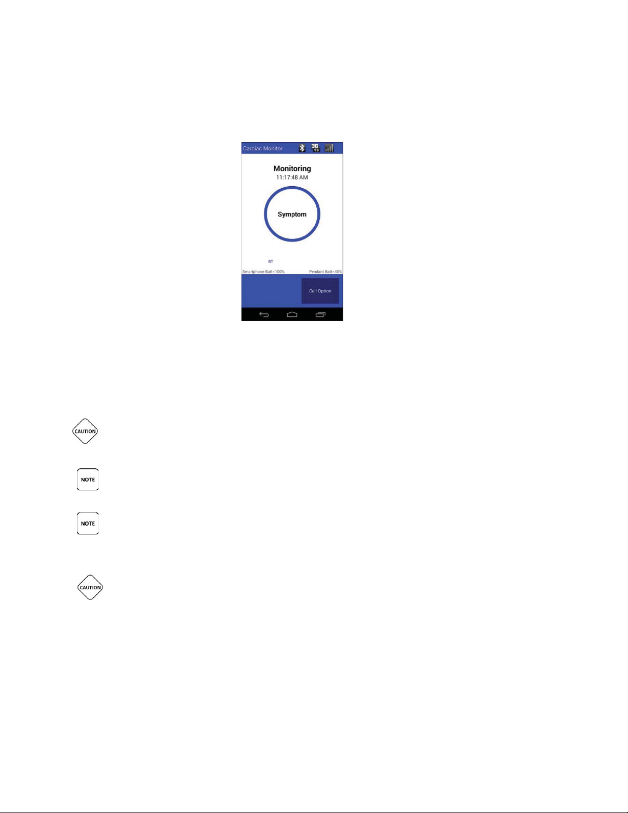
The TelePatch system will first collect ECG data, then the ECG Data will appear on the
TelePatch™ Cardiac Monitor PM750
Call Medicomp’s Patient Support: 877-996-5553
Step 8 - Initial Procedure Screens
After applying and accepting the procedure settings, the procedure will initialize.
Initializing Procedure
●
ECG Baseline Reading
screen for a short time, then the screen will display “Monitoring.”
● 'Monitoring' will be displayed the majority of the time during a procedure.
USER MANUAL - UTM0000701-05E
43
| APRIL 4, 2019
Page 44
Have a question or need assistance?
The Medicomp TelePatch Handset
The TelePatch procedure is now running.
THE TELEPATCH SYSTEM IS DESIGNED TO OPERATE IN ENVIRONMENTS THAT MAY
TELEPATCH IS DESIGNED TO BE RESISTANT TO SUCH EVENTS AND WILL TYPICALLY CONTINUE
TELEPATCH SHALL RESUME NORMAL OPERATION WITH NO LOSS OF FUNCTIONALITY OR
TelePatch™ Cardiac Monitor PM750
Call Medicomp’s Patient Support: 877-996-5553
Monitoring Screen
●
IT IS VERY IMPORTANT TO TURN THE PENDANT OFF BEFORE CHANGING BATTERY,
OTHERWISE DATA MAY BE LOST. THE POWER BUTTON IS LOCATED ON THE FACE OF THE
PENDANT.
DEPENDING ON THE SETTINGS, AND THE PATIENT PREPARATION, SOME INTERMITTENT
CONFIRMATION AND/OR ERROR SCREENS MAY APPEAR DURING THE INITIALIZATION.
PLEASE PERIODICALLY CHECK THE PENDANT AND/OR Handset TO ENSURE THEY ARE
BOTH IN MONITORING MODE. THIS MEANS THE PENDANT IS BLINKING BLUE LED LIGHTS,
AND THE Handset DISPLAY STATES ‘MONITORING’.
EXPERIENCE TRANSIENT ELECTRICAL EVENTS LIKE ELECTROSTATIC DISCHARGE (ESD).
TO OPERATE NORMALLY. A SEVERE ESD EVENT MAY CAUSE THE DEVICE TO SHUT DOWN IN
ORDER TO PROTECT THE MEMORY. IF A SHUTDOWN OCCURS, MANUALLY POWER THE DEVICE
ON USING THE POWER BUTTON ON THE FRONT OF THE DEVICE. ONCE POWERED ON,
INFORMATION.
Best Practices for using the Handset and the Pendant:
USER MANUAL - UTM0000701-05E
44
| APRIL 4, 2019
Page 45
Have a question or need assistance?
Recording Symptoms: Standard TelePatch Procedure
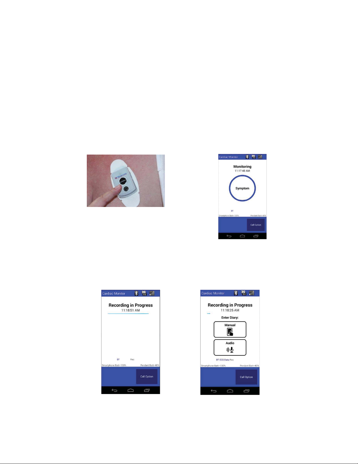
has two raised bars so it can be easily located.
Press SYMPTOM on Universal Pendant
OR Press SYMPTOM on Handset
The TelePatch Handset will display Recording in Progress for 60 seconds.
The TelePatch Handset will light up with a message to make a Diary Entry.
TelePatch™ Cardiac Monitor PM750
Call Medicomp’s Patient Support: 877-996-5553
● Keep the Handset charged and turned on.
● Keep Handset within 10’ of the Pendant during procedure.
● Review how to record a SYMPTOM, make a Diary Entry.
● Review how to charge the Handset daily.
● Review how to change and charge the Pendant battery.
When a Symptom is felt, or at other times as directed by your physician:
● Press the SYMPTOM button on the Pendant or on the Handset, to record heart’s
activity.
The SYMPTOM button on the Pendant
●
●
USER MANUAL - UTM0000701-05E
45
| APRIL 4, 2019
Page 46
Have a question or need assistance?
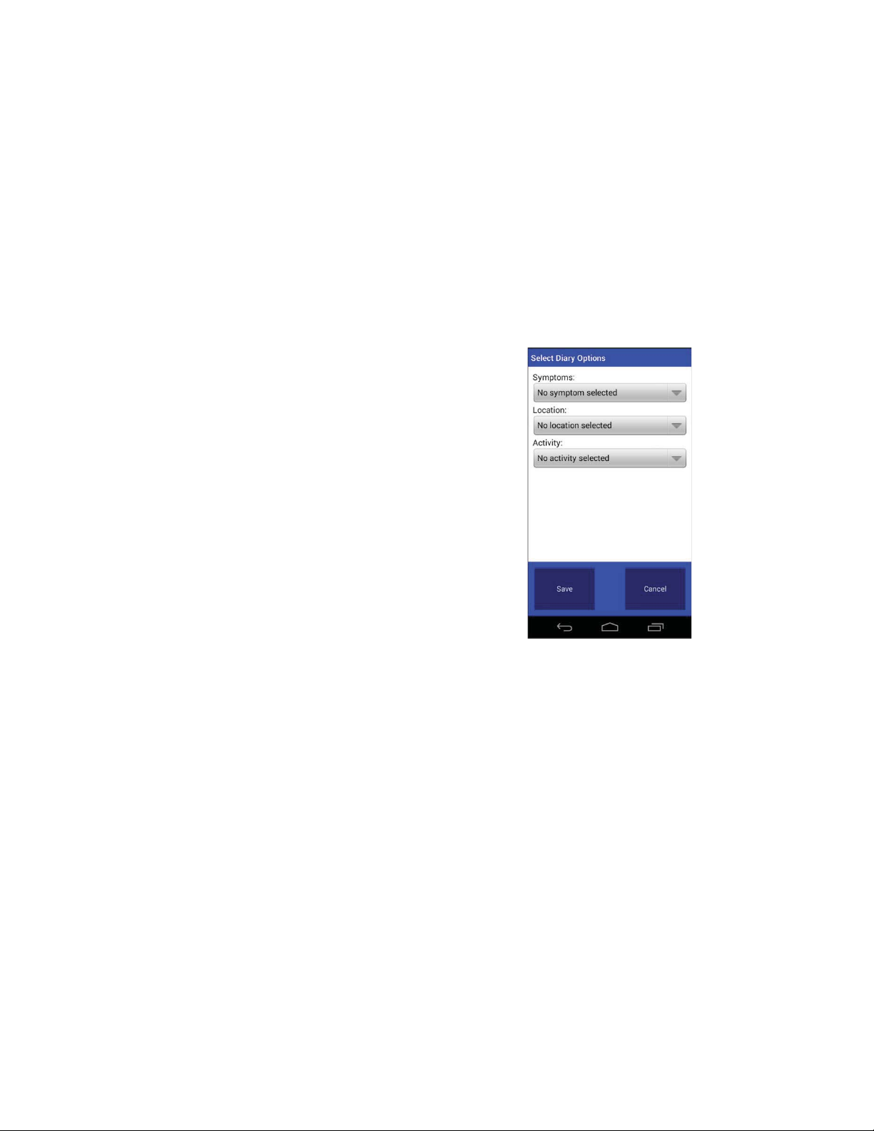
Select Diary Options Screen – Options chosen
*The screen may return to “Recording in Progress”, Handset screen will return to “Monitoring”
TelePatch™ Cardiac Monitor PM750
Call Medicomp’s Patient Support: 877-996-5553
How to Make a Diary Entry:
It is important the prescribing physician to know when a symptom is felt and activity at the time
the SYMPTOM button was pressed:
● While “Recording in Progress” is displayed on the Handset, Diary options will be
displayed
Manual Diary Entry:
● Tap “Manual”.
● Below the word Symptom Tap ”No
symptom selected”.
● Choose a symptom from the list.
● Tap “Save”.
● Below the word “Location” Tap ”No
location selected”.
● Choose a location from the list.
● Tap “Save”.
● Below the word “Activity” Tap” No
activity selected”.
● Choose an activity from the list.
● Tap “Save”.
● From the Select Diary Options screen
(showing options picked) Tap “Save”.
● The “Monitoring” display will return*.
as soon as recording period is complete.
USER MANUAL - UTM0000701-05E
46
| APRIL 4, 2019
Page 47
Have a question or need assistance?
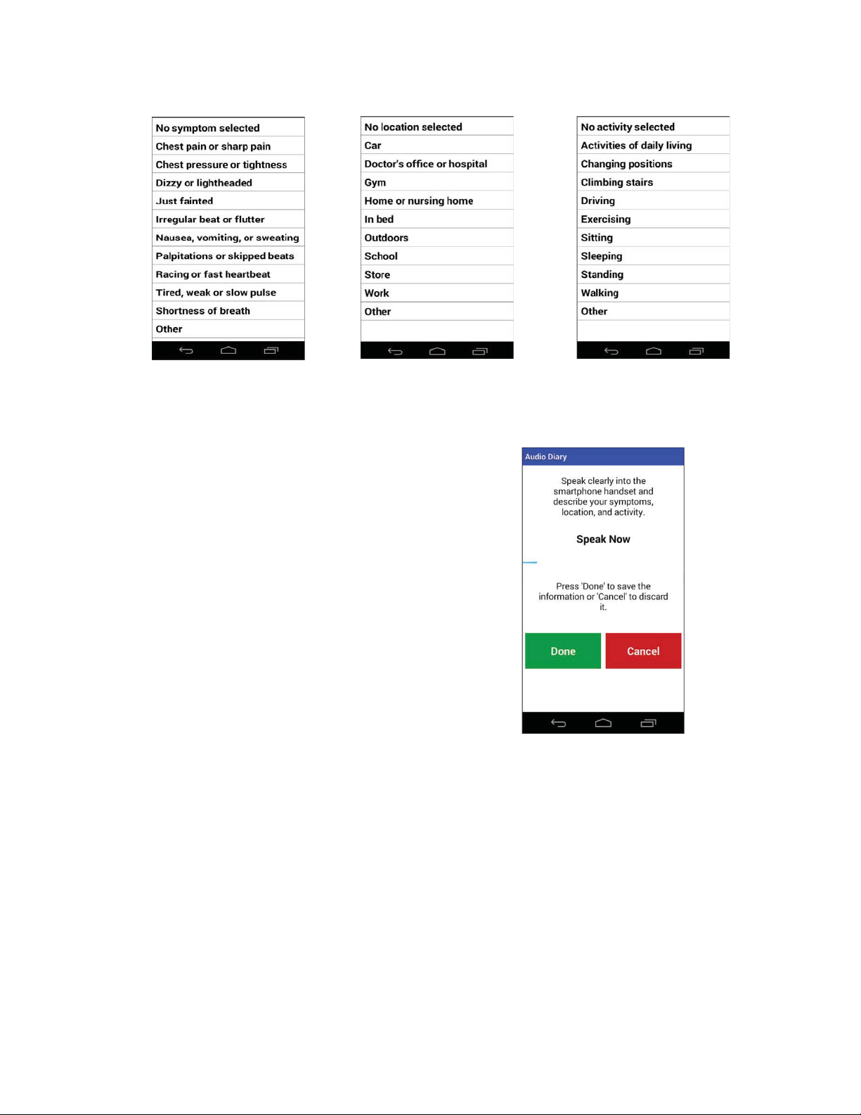
Symptom Menu
Location Menu
Activity Menu
If wearing TelePatch Cradle and Pendant with individual electrodes, start preparation here
This section contains step-by-step instructions that describe how to prepare TelePatch System
and skin for a TelePatch Cable Cradle with Cable procedure - (requires individual chest
TelePatch™ Cardiac Monitor PM750
Call Medicomp’s Patient Support: 877-996-5553
Audio Diary Entry:
● Tap “Audio”.
● Clearly state the symptom, location
where symptom occurred, and activity
during symptom.
● Tap “Done”.
● The “Monitoring” display will return*.
*The screen may return to “Recording in Progress”, Handset
screen will return to “Monitoring” as soon as recording period is
complete.
PROCEDURE SET-UP: Cable Cradle with Patient Cable
USER MANUAL - UTM0000701-05E
47
Patient Preparation
| APRIL 4, 2019
Page 48

Have a question or need assistance?
Electrode Placement for the TelePatch Procedure
5-Wire Hook-up: Lead II and a modified Lead V1 or MCL1 are used with the TelePatch Cable
3-Wire Hook-up: Lead II and Lead I are used. [Referring to the Medicomp reports, the ECG
TelePatch™ Cardiac Monitor PM750
Call Medicomp’s Patient Support: 877-996-5553
electrode patch application). Please follow the skin preparation sequence as closely as possible.
This will greatly enhance the ECG signal quality and optimize analysis.
Step 1 - Identify Electrode Sites
Cradle procedure, which provides two-channel, ambulatory monitoring. "A" in the table below
corresponds to Lead II. "B" in the table corresponds to V1/MCL1. [Referring to the Medicomp
reports, the ECG strips show Lead II at the top, and Lead V1/MCL1 on the bottom.
strips show Lead II at the top, and Lead I on the bottom
.
Refer to the figures below for proper electrode placement:
3-Wire Hook-Up
5-Wire Hook-Up
A- WHITE A- WHITE
A+ / B+ RED A+ RED
B- BLACK B- BLACK
B+ BROWN
USER MANUAL - UTM0000701-05E
48
G GREEN
| APRIL 4, 2019
Page 49

Have a question or need assistance?
TelePatch™ Cardiac Monitor PM750
Call Medicomp’s Patient Support: 877-996-5553
3-Wire Hook-up 5-Wire Hook-up
For women with large breasts, the following electrode positions are recommended:
● Red in the left axillary line
● Black in the right axillary line
This lead placement may eliminate potential skin prep problems and minimizes occurrences of
artifact.
Step 2 - Prepare the Skin
In order to obtain the best ECG recording, the following procedure is recommended for initial
patient hookup:
1. Whenever possible, be in an upright sitting position. This may be useful if any setup
problems occur that concern the signal voltage.
2. Following the lead placement diagram, select sites that are flat and bony. Avoid skin
folds or creases, irritated skin or scar tissue, and highly muscular areas.
3. If necessary, shave an area at each electrode site slightly larger than the size of the
electrode.
4. If powder, lotion, sunblock, etc. has been applied to the chest, or if skin is excessively
oily, wash each site with plain soap and water. Do not use a soap that contains lotion or
oil.
5. Skin-prep pads (found in alcohol prep-pad type packaging) can be used to clean and
prepare skin for initial application.
USER MANUAL - UTM0000701-05E
49
| APRIL 4, 2019
Page 50
Have a question or need assistance?
TelePatch™ Cardiac Monitor PM750
Call Medicomp’s Patient Support: 877-996-5553
The above skin prep procedure is only required at the beginning of the procedure, during
Handset initialization. Users will not be required to perform this type of preparation each time
they relocate electrodes. It is best for users to have freshly showered with plain soap each time
they apply new electrodes. When the Pendant is reconnected to the patient cable, the unit
performs a less restrictive setup.
● If electrodes have connectivity issues the skin can be lightly abraded each electrode site
with a rough washcloth, or an abrasive pad
ALLOW 15 MINUTES FOR SKIN TO ABSORB THE ELECTRODE GEL, WHICH MAY HELP
PROCEDURE INITIATION ERRORS FROM OCCURRING.
CONDUCTIVE PARTS OF ELECTRODES AND ASSOCIATED CONNECTORS FOR TYPE BF OR
CF APPLIED PARTS, INCLUDING NEUTRAL ELECTRODE, SHOULD NOT CONTACT OTHER
CONDUCTIVE PARTS, INCLUDING EARTH.
Step 3 - Snap on Electrodes and Set Up Cable Cradle
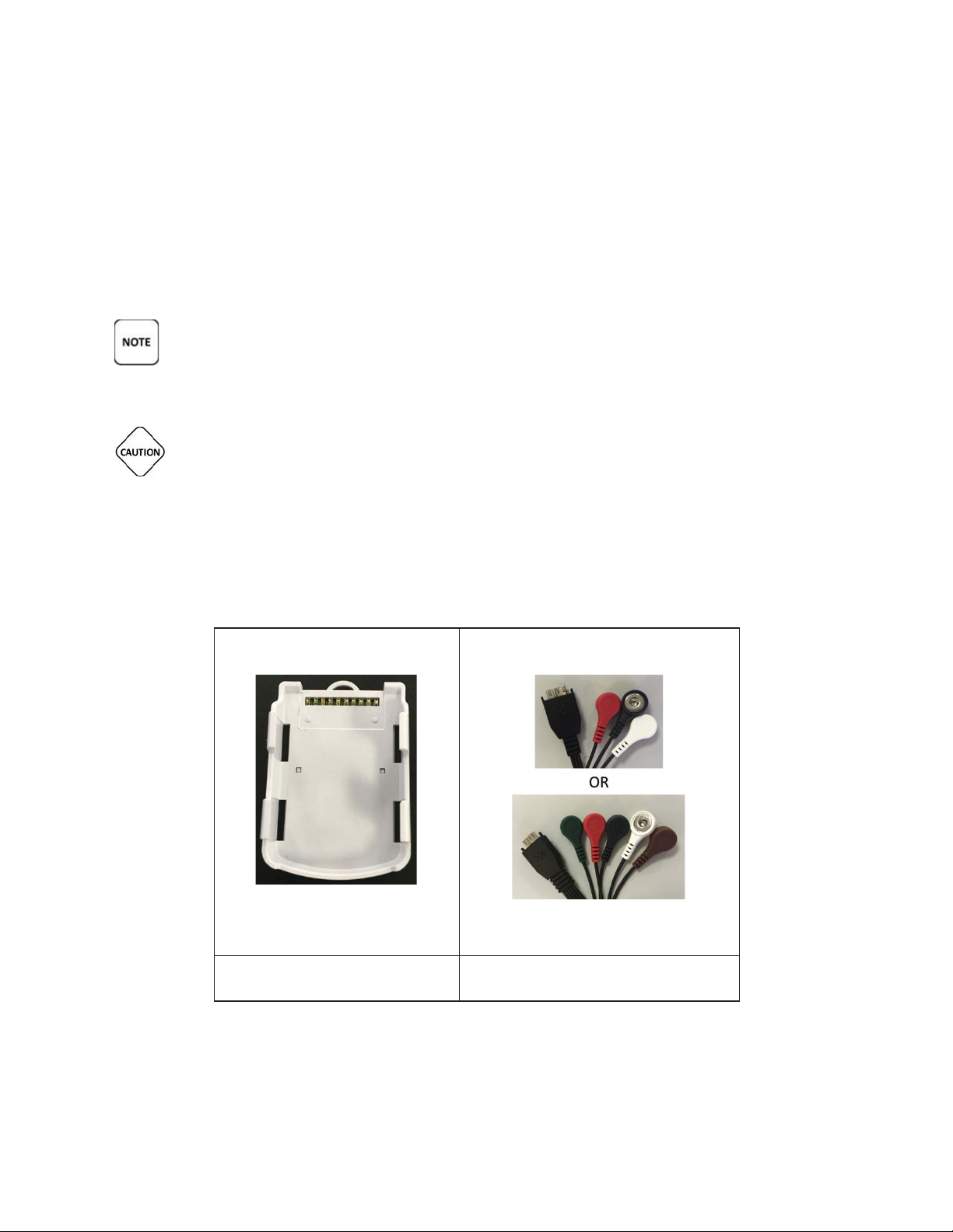
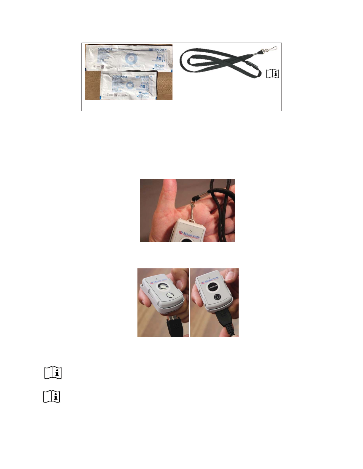
Locate the Cable Cradle, one battery, lead wires, envelope of electrodes and lanyard (optional).
USER MANUAL - UTM0000701-05E
50
| APRIL 4, 2019
Page 51
Have a question or need assistance?
LANYARD IS NOT TO BE WORN WHILE SLEEPING.
TelePatch™ Cardiac Monitor PM750
Call Medicomp’s Patient Support: 877-996-5553
● Snap the wires onto the electrodes while they are still attached to the plastic backing.
● One by one, peel each electrode from the backing and apply it to the chest.
● Position the electrodes at the appropriate color-coded sites.
● If wearing cable cradle on lanyard, clip lanyard onto the loop at the top of cradle.
○ Cable Cradle may also be carried in pocket, be careful Cable remains connected
to Cable Cradle
● Hold flat plug at the end of electrodes cable and connect cable to the base of cradle into
the corresponding outlet.
● Place the lanyard over head to wear the cradle with cable attached.
CHILDREN WEARING PENDANTS MUST BE SUPERVISED BY ADULTS.
USER MANUAL - UTM0000701-05E
51
| APRIL 4, 2019
Page 52

Have a question or need assistance?
IT IS VERY IMPORTANT TO TURN THE PENDANT OFF BEFORE CHANGING BATTERIES,
TelePatch™ Cardiac Monitor PM750
Call Medicomp’s Patient Support: 877-996-5553
PEOPLE WORKING WITH MACHINERY OR WORKING IN ENVIRONMENTS WHERE LOOSE
HANGING ROPE- LIKE OBJECTS CAN POSE A POTENTIAL THREAT OR HARM TO
THEMSELVES AND/OR THE MACHINERY ARE ADVISED TO CARRY CABLE CRADLE WITH
PENDANT IN POCKET.
THE BREAKAWAY LANYARD IS TO BE DISPOSED OF AS HOUSEHOLD WASTE FOLLOWING
THE PROCEDURE.
WARNING: CHOKING HAZARD – ADULT SUPERVISION REQUIRED.
OTHERWISE DATA MAY BE LOST. THE POWER BUTTON IS LOCATED ON THE FRONT OF THE
PENDANT.
Step 4 - Start Pendant:
● Follow directions for starting Pendant on page 32.
Step 5 - Starting the Handset:
● Follow directions for starting Handset on page 35.
Step 6 - Procedure Set Up:
● Follow directions for initiating procedure on page 35.
Step 7 - Procedure Settings:
● Follow directions for initial procedure set up on page 36.
Step 8 - Initial Procedure Screens:
● Follow directions for completing procedure set up on page 39.
Recording Symptoms: Cable Cradle Procedure
● Follow directions for Recording a Symptom on page 41.
Procedure while wearing the Cable Cradle:
● Wear the Cable Cradle and Pendant all day and all night - except when showering.
● The Cable Cradle can be worn on the included break-away lanyard or can be kept in
pocket (make sure Cable stays firmly attached).
● The Cable Cradle and Pendant should go into a pocket of a nightshirt while sleeping:
○ Do not wear the lanyard at night while sleeping.
● The physician will tell you the duration of your procedure.
USER MANUAL - UTM0000701-05E
52
| APRIL 4, 2019
Page 53

Have a question or need assistance?
TelePatch™ Cardiac Monitor PM750
Call Medicomp’s Patient Support: 877-996-5553
● The Pendant should always be in the Cable Cradle, the Cable should remain plugged into
the Cable Cradle.
● Enjoy all of your regular activities like exercise or gardening, while wearing the Pendant,
and Cable Cradle with Cable.
● DO NOT shower with the Cable Cradle and Cable:
○ Turn off the Pendant by pressing the Power Button.
○ Unsnap the cable heads from the electrodes.
○ Leave Cable Cradle, Cable, Pendant (and lanyard) outside the
shower.
○ Electrodes may be worn in the shower - fresh electrodes may
need to be applied following the shower.
● After showering and dry, put on the lanyard with Cable Cradle and Pendant, re-attach
electrodes, turn on Pendant.
PROCEDURE SET-UP: Fingertip Electrodes
If using Fingertip Electrodes for procedure, start preparation here.
Step 1 - Start Pendant:
● Follow directions for starting Pendant on page 32.
Step 2 - Starting the Handset:
● Follow directions for starting Handset on page 35.
Step 3 - Procedure Set Up:
● Follow directions for initiating procedure on page 35.
Step 4 - Procedure Settings:
● Follow directions for initial procedure set up on page 36.
Step 5 - Initial Procedure Screens:
● Follow directions for completing procedure set up on page 39.
Recording Symptoms: Fingertip Electrode Procedure
When experiencing a symptom, or at other times as directed by physician:
● Remove the Pendant from pocket or cable cradle.
● Press the SYMPTOM button on the Pendant or on the Handset.
USER MANUAL - UTM0000701-05E
53
| APRIL 4, 2019
Page 54
Have a question or need assistance?
How Do I Wear TelePatch System: Electrode Patch and Pendant?
How Do I Wear TelePatch System: Pendant, Cable Cradle With Electrodes?
TelePatch™ Cardiac Monitor PM750
USER MANUAL - UTM0000701-05E | APRIL 4, 2019
Call Medicomp’s Patient Support: 877-996-5553
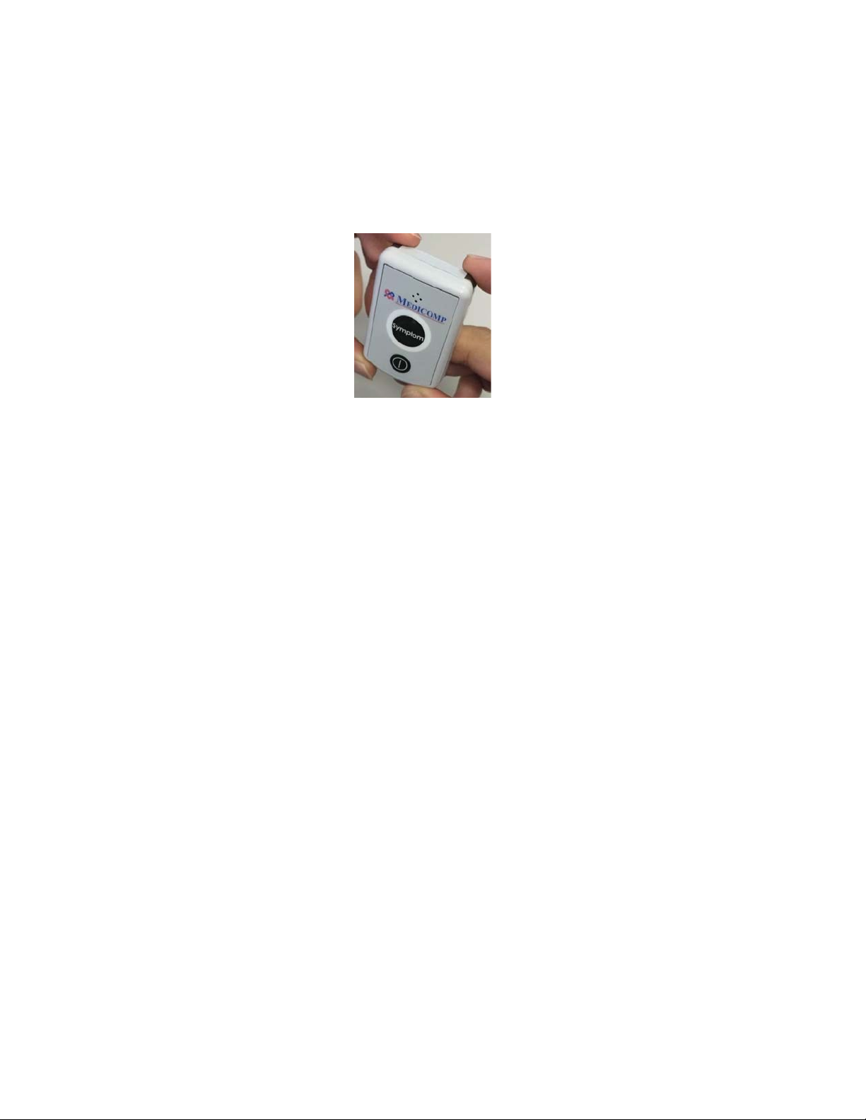
● Place index fingers firmly on the Fingertip Electrodes (the silver-gray corners) on the top
edge of the Pendant for 30 seconds.
● Handset will display “Recording in Progress”, keep fingers on the Fingertip Electrode
corners until the Handset screen message says “Recording Complete”
● The Handset will light up and a message will remind user to make a Diary Entry:
○ See page 42 for instructions on making a Diary entry.
Procedure while using and Pendant and Fingertip Electrodes:
● Carry the Pendant all day and have it nearby at night.
● Charge Handset daily.
● The physician will determine the duration of the procedure.
● Enjoy all regular activities like exercise or gardening, during procedure.
COMMON QUESTIONS
The Universal Pendant
is securely held in the Electrode Patch cradle, and won’t interfere with
day to day activities. Make sure the Symptom button (on the Pendant or Handset) is easily
accessible.
You can wear the Cable Cradle on the breakaway Lanyard, or keep it in your pocket. Make sure
the cable stays plugged into the Cable Cradle at all times. When wearing Cable Cradle avoid
areas where the buttons might accidentally be pressed. At bedtime place Cable Cradle next to
you where its location is the most comfortable. Do not wear the Lanyard when sleeping.
54
Page 55

Have a question or need assistance?
TelePatch™ Cardiac Monitor PM750
USER MANUAL - UTM0000701-05E | APRIL 4, 2019
Call Medicomp’s Patient Support: 877-996-5553
Can I Shower?
When wearing the Universal Pendant
with the Electrode Patch you can shower with the
Pendant and patch on. When done in the shower gently pat (not rub) the face of the patch and
the Pendant dry. Remove the Pendant from the patch cradle to dry behind the Pendant, then
reinsert in the cradle immediately.
When wearing the Cable Cradle with cable DO NOT wear the Cable Cradle or cable in the
shower.
1. Disconnect the cable from the Pendant and set the unit aside.
2. Unsnap the wires from electrodes. A diagram in the Patient Guide will help you to
replace them correctly when re-connecting.
Remove electrodes if skin is very irritated or if it has been 72 hours or more (per electrode
manufacturer's directive) since the last electrode change. If you don't need to remove the
electrodes, just make sure that water does not fall directly on them.
Tip For During Shower
The Electrode Patch and Pendant are water resistant. They will withstand brief periods in
contact with water – such as when showering. You can and should wear the Electrode Patch
and Pendant while showering but do not submerge or soak the devices in water.
If it is time to remove the electrodes, try removing them during your shower after they have
become thoroughly soaked with water. This will make removal easier.
Tip For After Shower
Please make sure to dry both the pendant and the cradle that holds the pendant after getting
wet.
If you are replacing Electrode Patch or single electrodes: After showering, determine where
electrode will be placed (refer to the diagram in the Patient Guide for placement) and dry your
skin well in those areas.
If wearing the Cable Cradle with individual electrodes: Snap the wires onto the electrodes. Now,
carefully remove the back plastic cover from each electrode in turn and press the electrodes to
your skin so that complete contact is made with the adhesive backing. Plug the cable into the
Cable Cradle if it has been unplugged. Make sure the Pendant is turned on. The Handset will
resume receiving data from the Pendant.
55
Page 56
Have a question or need assistance?
Stress Loops are only applicable to the TelePatch Cable Cradle procedure. Stress loops are
Note: Stress loops are not provided by Medicomp Inc.
TelePatch™ Cardiac Monitor PM750
iac Motor PMPMPMPMPMPMPM0
Call Medicomp’s Patient Support: 877-996-5553
Stress Loops
recommended. Two examples of stress loops are shown below.
Lead Wire Stress Loops
This is a good way to secure lead wires to prevent pulling, thus minimizing noise interference
during the procedure. Wear the Cable Cradle with the lanyard or keep the Cable Cradle in a
pocket.
EMERGENCY AND SUPPORT NUMBERS
Call 911
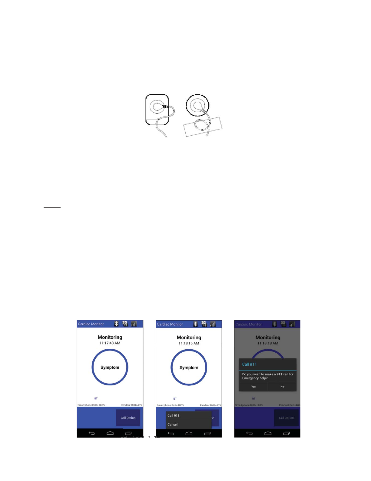
Below are instructions on how to call 911 from the Handset.
From the 'Monitoring' screen
● Tap “Call Option”
● Tap “Call 911”
● Tap “YES“
• Hang up the call with the End Key
USER MANUAL - UTM0000701-05E
56
| APRIL 4, 2019
Page 57

Have a question or need assistance?
HANDSET AS THE HANDSET WILL IMMEDIATELY LAUNCH A PROCESS THAT WILL
THE UNIVERSAL PENDANT IS WATER RESISTANT. YOU CAN SHOWER WITH THE
TelePatch™ Cardiac Monitor PM750
Call Medicomp’s Patient Support: 877-996-5553
PROCEDURE INFORMATION AND CAUTIONS
TELEPATCH SYSTEM WHEN WEARING ELECTRODE PATCH
● ALLOW 15 MINUTES FOR SKIN TO ABSORB THE ELECTRODE GEL, WHICH MAY
HELP PROCEDURE INITIALIZATION ERRORS FROM OCCURRING.
● UNLESS OTHERWISE INSTRUCTED, WEAR THE TELEPATCH CONTINUOUSLY
DURING NORMAL DAILY ACTIVITIES.
● TURN THE PENDANT ON BEFORE TAPPING “START PROCEDURE” ON THE
START COMMUNICATION TO THE PENDANT VIA BLUETOOTH TECHNOLOGY. IF
THE PENDANT IS NOT TURNED ON AT THAT TIME, THE H
ANDSET WILL NOT BE
ABLE TO IDENTIFY THE PENDANT
● PENDANT BATTERY IS UP TO SEVEN (7) DAYS. CHANGE THE BATTERY WHEN
THE PENDANT BATTERY INDICATOR ON THE HANDSET READS 15% OR LESS.
● IT IS VERY IMPORTANT TO TURN THE PENDANT OFF BEFORE REMOVING AND
LOADING BATTERY, OTHERWISE DATA MAY BE LOST. REMINDER: THE POWER
BUTTON IS LOCATED ON THE FACE OF THE PENDANT, BELOW THE SYMPTOM
BUTTON.
● HEAVY EXERCISE OR OTHER ACTIVITIES THAT EXPOSE THE TELEPATCH TO
MOISTURE CAN AFFECT PATCH ADHESION DURATION. IF A PATCH
SELF-REMOVES DUE TO EXERCISE OR ACTIVITY, CLEAN THE AREA AS NOTED
IN THE PATIENT GUIDE AND APPLY A NEW PATCH.
● THE PENDANT AND BATTERY ARE NOT DISPOSABLE. THE PENDANT SHOULD
BE REMOVED FROM THE CRADLE ON THE ELECTRODE PATCH AND PLACED IN
THE CRADLE OF THE FRESH ELECTRODE PATCH, NOT DISCARDED WITH
REMOVED ELECTRODE PATCH.
●THE U
NIVERSAL PENDANT SHOULD NOT BE TREATED AS HOUSEHOLD WASTE.
● ONLY THE ELECTRODE PATCH SHOULD BE DISCARDED AFTER USE.
● RETURN UNIVERSAL PENDANT AND ALL COMPONENTS IN KIT PROVIDED, TO
MEDICOMP, INC., USING THE INCLUDED POSTAGE PAID ENVELOPE.
SHOWERING OR SWIMMING WITH TELEPATCH SYSTEM AND ELECTRODE PATCH
●
NIVERSAL PENDANT AND ELECTRODE PATCH INTACT.
U
NIVERSAL PENDANT AND ELECTRODE PATCH ARE NOT WATERPROOF, MEANING
●U
THE PENDANT COULD CEASE TO FUNCTION IF FULLY SUBMERGED IN WATER
FOR A PERIOD OF TIME. AVOID SWIMMING AND FULL SUBMERSION INTO
WATER, WHILE WEARING TELEPATCH.
● REMOVE U
INTACT ON THE SKIN IF SUBMERGED IN WATER FOR AN EXTENDED PERIOD OF
TIME.
USER MANUAL - UTM0000701-05E
57
NIVERSAL PENDANT BEFORE SWIMMING. THE PATCH WILL NOT REMAIN
| APRIL 4, 2019
Page 58

Have a question or need assistance?
BUTTON IS LOCATED ON THE FACE OF THE PENDANT, BELOW THE SYMPTOM
TelePatch™ Cardiac Monitor PM750
USER MANUAL - UTM0000701-05E | APRIL 4, 2019
Call Medicomp’s Patient Support: 877-996-5553
● DO NOT WEAR ELECTRODE PATCH OR UNIVERSAL PENDANT SWIMMING OR
SUBMERGED IN WATER DURING PROCEDURE.
TELEPATCH SYSTEM WHEN USING CABLE CRADLE
● ALLOW 15 MINUTES FOR SKIN TO ABSORB THE ELECTRODE GEL, WHICH MAY
HELP PROCEDURE INITIALIZATION ERRORS FROM OCCURRING.
● TURN THE PENDANT ON BEFORE TAPPING “START PROCEDURE” ON THE
ANDSET AS THE HANDSET WILL IMMEDIATELY LAUNCH A PROCESS THAT WILL
H
START COMMUNICATION TO THE PENDANT VIA BLUETOOTH TECHNOLOGY. IF
THE PENDANT IS NOT TURNED ON AT THAT TIME, THE H
ANDSET WILL NOT BE
ABLE TO IDENTIFY THE PENDANT
● IT IS VERY IMPORTANT TO TURN THE PENDANT OFF BEFORE REMOVING AND
LOADING BATTERY, OTHERWISE DATA MAY BE LOST. REMINDER: THE POWER
BUTTON.
● IF WEARING TELEPATCH WITH A CABLE CRADLE AND INDIVIDUAL ELECTRODES
IT IS RECOMMENDED TO PLACE THE PENDANT IN A POCKET DURING EXERCISE
OR OTHER ACTIVITIES. IF INDIVIDUAL ELECTRODES SELF-REMOVE DURING
ACTIVITY, CLEAN THE AREAS AND APPLY NEW ELECTRODES. AVOID FULL
IMMERSION INTO WATER (POOLS, HOT TUBS, OPEN WATER SWIMMING).
● BREAKAWAY LANYARD IS NOT TO BE WORN WHILE SLEEPING.
● CHILDREN WEARING PENDANTS MUST BE SUPERVISED BY ADULTS.
● PEOPLE WORKING WITH MACHINERY OR WORKING IN ENVIRONMENTS WHERE
LOOSE HANGING ROPE- LIKE OBJECTS CAN POSE A POTENTIAL THREAT OR
HARM TO THEMSELVES AND/OR THE MACHINERY ARE ADVISED TO CARRY
CABLE CRADLE WITH PENDANT IN POCKET.
● THE CABLE CRADLE SHOULD NOT BE WORN IN THE SHOWER.
●THE U
NIVERSAL PENDANT SHOULD NOT BE TREATED AS HOUSEHOLD WASTE.
● THE INDIVIDUAL ELECTRODES SHOULD BE DISCARDED AFTER USE.
● THE BREAKAWAY LANYARD SHOULD BE DISCARDED AFTER USE.
● RETURN UNIVERSAL PENDANT, AND ALL COMPONENTS IN KIT PROVIDED, TO
MEDICOMP, INC., USING THE INCLUDED POSTAGE PAID ENVELOPE.
SHOWERING OR SWIMMING WITH TELEPATCH SYSTEM AND CABLE CRADLE
● THE CABLE CRADLE SHOULD NOT BE WORN IN THE SHOWER.
● WHEN WEARING TELEPATCH WITH A CABLE CRADLE AND INDIVIDUAL
ELECTRODES: BEFORE TAKING A SHOWER OR BATH, UNSNAP THE LEAD
WIRES FROM THE ELECTRODES (THAT ARE ATTACHED TO CHEST) REMOVE
THE CABLES, CABLE CRADLE AND LANYARD BEFORE ENTERING SHOWER..
● WATER WILL NOT AFFECT THE INDIVIDUAL ELECTRODES; DO NOT REMOVE
THEM BEFORE SHOWERING IF THEY ARE STILL FIRMLY ATTACHED TO THE
58
Page 59

Have a question or need assistance?
HANDSET IS POWERED BY THE CHARGER CORD ONCE CHARGER CORD IS
UNPLUG THE CHARGER CORD FROM THE HANDSET BEFORE PLACING HANDSET IN
TelePatch™ Cardiac Monitor PM750
Call Medicomp’s Patient Support: 877-996-5553
SKIN. IF AN INDIVIDUAL ELECTRODE SELF-REMOVES IN SHOWER, PREPARE
THE AREAS AND APPLY NEW ELECTRODES.
● IF SHOWERING WITH ELECTRODES, GENTLY PAT THEM DRY WITH A TOWEL
BEFORE RECONNECTING THE LEAD WIRES TO THE ELECTRODES
● IF SWIMMING, REMOVE CABLE, CABLE CRADLE AND PENDANT BEFORE
SUBMERGING INTO WATER. USER MAY LEAVE ELECTRODES ON IF THEY ARE
STILL FIRMLY ATTACHED TO THE SKIN.
HANDSET / HANDSET
● TURN THE PENDANT ON BEFORE TAPPING “START PROCEDURE” ON THE
ANDSET AS THE HANDSET WILL IMMEDIATELY LAUNCH A PROCESS THAT WILL
H
START COMMUNICATION TO THE PENDANT VIA BLUETOOTH TECHNOLOGY. IF
THE PENDANT IS NOT TURNED ON AT THAT TIME, THE HANDSET WILL NOT BE
ABLE TO IDENTIFY THE PENDANT
● MAKE SURE WALL OUTLET IS NOT CONTROLLED BY A LIGHT SWITCH.
● CHARGER CORD MUST NOT BE OBSTRUCTED BY FURNITURE OR LARGE
OBJECTS AND REMAIN ACCESSIBLE TO DISCONNECT FROM WALL OUTLET
EASILY, AS NEEDED.
●
PLUGGED INTO BOTH H
ANDSET AND WALL OUTLET.
● WHEN CHARGING IS COMPLETE, UNPLUG THE CHARGER CORD FROM THE
POWER OUTLET AND THE H
●
ANDSET.
POCKET OR PURSE/BRIEFCASE.
● DO NOT WEAR THE HANDSET WHILE THE CHARGER IS ATTACHED TO THE HANDSET.
BATTERY CHARGER
● BATTERY CHARGER IS POWERED BY THE CHARGER CORD ONCE CHARGER
CORD IS PLUGGED INTO BATTERY CHARGER AND THEN A WALL OUTLET.
● MAKE SURE WALL OUTLET IS NOT CONTROLLED BY A LIGHT SWITCH.
● CHARGER CORD MUST NOT BE OBSTRUCTED BY FURNITURE OR LARGE
OBJECTS AND REMAIN ACCESSIBLE TO DISCONNECT FROM WALL OUTLET
EASILY, AS NEEDED.
● BATTERY CHARGER LIGHT WILL FLASH AMBER OR ORANGE WHILE BATTERY IS
CHARGING.
● BATTERY CHARGER LIGHT WILL BE GREEN WHEN BATTERY IS FULLY
CHARGED.
● BATTERY CHARGER LIGHT MAY FLASH RED WHEN BATTERY IS NOT INSTALLED
IN CHARGER PROPERLY.
● IF BATTERY CHARGER HAS NO INDICATOR LIGHT LIT NEXT TO CABLE PLUG,
VERIFY CHARGER CORD IS PLUGGED INTO BATTERY CHARGER AND OUTLET
PROPERLY.
USER MANUAL - UTM0000701-05E
59
| APRIL 4, 2019
Page 60

Have a question or need assistance?
CAUTION: Portable and mobile RF communications equipment can affect medical electrical
NOTE: EUT (PM750 Pendant) shuts down between +/-8 and 15kV Air Discharge. It is
WARNING: When using lead wires, they should not contact other conductive equipment or
Cleaning the TelePatch System
The Universal Pendant may need to be cleaned if for any reason it becomes exposed to
biological materials, like body fluids or matter. The user should clean the TelePatch Monitoring
TelePatch™ Cardiac Monitor PM750
Call Medicomp’s Patient Support: 877-996-5553
● IF BATTERY CHARGER HAS NO INDICATOR LIGHT LIT NEXT TO CABLE PLUG,
VERIFY BATTERY IS PLACED IN CHARGER PROPERLY.
● WHEN CHARGING IS COMPLETE, UNPLUG THE CHARGER CORD FROM THE
POWER OUTLET AND THE BATTERY CHARGER.
PENDANT PRECAUTIONS
equipment. This Pendant should not be used adjacent to or stacked with other equipment in
accordance with the directions described in the Practice Reference Manual.
recommended that you restart the device (wait 30 seconds after power down) upon occurrence
of this event.
electric ground, including earth.
● Lead failures are detected by a 10 mV peak, 50% duty cycle rectangular pulse, which is
applied to each patient electrode connection through a 4.9Mohm resistor at a rate of 15
Hz with respect to the system ground.
● This is a prescribed medical Pendant, not a toy; keep away from small children.
● In the event of a damaged Pendant, discontinue use and call Medicomp’s Patient
Support: 877-996-5553, for return and replacement.
ADVERSE REACTIONS
In the event of irritation worse than minor itching from the Electrode Patch or individual
electrodes, consult your physician. Users may also contact Medicomp to discuss alternatives.
Physicians must contact Medicomp to request change of procedure. Medicomp cannot
authorize change of patient procedure.
● Signs of significant irritation where the electrode patch is in contact with the skin.
● Any other unanticipated reaction to the adhesive or the electrode gel.
MAINTENANCE
System in order to maintain optimal use and functionality.
USER MANUAL - UTM0000701-05E
60
| APRIL 4, 2019
Page 61

Have a question or need assistance?
or Pendant of the TelePatch System. If the Pendant has been dropped in a basin of water (i.e.:
simultaneously for 1.5 seconds.
second per frequency while
Beep 4 times in unison with
TelePatch™ Cardiac Monitor PM750
Call Medicomp’s Patient Support: 877-996-5553
Use a tissue, lightly moistened with alcohol or a hospital-grade cleanser such as Sporicidin –
(Do not saturate) - wipe off debris, dirt or other matter that may gather on either the Handset
sink or toilet) and will not power back on, contact Customer Support for a replacement.
VISUAL AND AUDIBLE INDICATORS
Normal Performance Indicators
Pendant Action Visual Indicator Audible Indicator
Pendant power up Green, blue, and orange lit
Pendant ready to start
Green LED blinks fast None
procedure
Procedure initiated: Press
Green LED solid for 1.5 seconds
Symptom button 3 times
(Holter Only)
Procedure initiated not in
cradle: Press Symptom
Orange and blue blinks fast in
unison
button 3 times (Holter
procedure only)
Procedure in progress: not in
cradle
Pendant removed from
Cradle
3 LED sections: continuous
flashing
3 LED sections: continuous
flashing
Beep High-Low-High for 0.5
LEDs are lit.
Beep High-Low-High for 0.5
second duration for each
beep
LEDs
None
None
Pendant placed in cradle with
procedure running BT
OFF/Holter
Symptom Button Press on
cables or patch: Record
Symptom
USER MANUAL - UTM0000701-05E
61
Green LED: every 4 seconds Beep for 2 seconds before
entering this mode for the
first time
Green LED lit for 1 second Beep for 1 second
| APRIL 4, 2019
Page 62
Have a question or need assistance?
Beep 3 times in unison with
Beep 3 times in unison with
up – running cradle and lead-
TelePatch™ Cardiac Monitor PM750
Call Medicomp’s Patient Support: 877-996-5553
Symptom Recording
Complete on Cables or Patch
“Recording Complete” message
will be seen on screen of
Handset
Finger Tip Electrodes Start of
Recording
Green LED 3 flashes 0.5 second
each then Green LED lit for 1
second
Finger Tip Electrodes during
Recording period
Finger Tip Electrode
Green LED flashes during 32
second recording period
Green LED lit for 1 second Beep for 1 second
Recording complete
Pendant communicating with
Blue LED: every 4 seconds None
Handset
Holter procedure end Green and blue blink
alternately at 2Hz
Pendant power down All three LEDs simultaneously
every 1.5 seconds
None
LED flashes then Beep for 1
second
None
None
lit LEDS.
Pendant Action Visual Indicator Audible Indicator
Pendant configuration wrong
New Holter procedure
power-
on/lead-off tests.
New Holter procedure
power-up, low main battery
error detected.
SYMPTOM button pressed,
Pendant not in cradle
SYMPTOM button pressed
while Pendant creating a
USER MANUAL - UTM0000701-05E
62
| APRIL 4, 2019
Error Indicators
Blink all three LEDs 5 times
for 0.5 seconds every second
Green blinks twice and blue
Beep 5 times in unison with
lit LEDs
None
blinks once repetitively
Orange LED blinks fast None
3 slow Green flashes, then
3 beeps then none
Green LED flashing fast
Green LED Flash Long beep
Page 63

Have a question or need assistance?
Beep 1 second duration every
Beep 1 second duration every
TelePatch. Reduce the likelihood of seeing errors by making sure fresh Electrode Patch or fresh
When the TelePatch is connected and begins its startup sequence, it assesses the quality of the
ECG signal. The TelePatch system will signal if there is a problem with the connections or if the
replacement or exchanged TelePatch system component (e.g. Handset or Pendant). Replaced
components of the TelePatch will follow a slightly different setup procedure than the standard
The TelePatch Quality Hookup tests evaluate cable connections, skin preparation, and
TelePatch™ Cardiac Monitor PM750
Call Medicomp’s Patient Support: 877-996-5553
recording
Early low main battery
warning
Late low main battery
warning
Orange LED blink 1 per
second
Orange LED blink 3 times per
second
4 minutes
30 seconds
TROUBLESHOOTING
Setup Details and Troubleshooting Overview
This section helps resolve any problems that may be encountered while you are setting up the
individual electrodes are used, as appropriate, the cable is in good condition and securely
connected to the Cable Cradle, and care has been taken to perform the recommended skin
preparation.
Some problems are unavoidable due to a patient's particular heart condition or the unexpected
failure of a component. However, these cases are infrequently encountered.
signal voltage is too high or too low for ideal auto-capturing. Messages on the Handset's display
will direct any necessary corrections.
Information is also provided in this section to assist with the setup procedure of any
method.
TelePatch System Hookup Testing Information
Quality Hookup Tests Overview
signal-voltage conditions. This is a test that is performed automatically by the TelePatch
System, with no indication to, or participation from, the user or patient until specifically
directed by specific commands on the Handset.
The Quality Hookup test starts once either:
USER MANUAL - UTM0000701-05E
63
| APRIL 4, 2019
Page 64
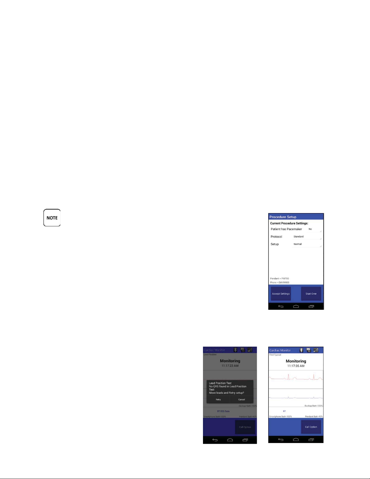
OR
The TelePatch System (Pendant and Handset) determines whether there is a problem and the
All TelePatch systems are shipped in the 'Setup/Normal' mode.
TelePatch™ Cardiac Monitor PM750
Have a question or need assistance?
Call Medicomp’s Patient Support: 877-996-5553
1. The patient has the electrode patch in place on the chest with the pendant secured in the
electrode patch cradle and the Handset is turned on to initiate the patient’s procedure.
2. The patient has the individual electrodes in place with the cable attached to both the
electrodes and the cable cradle, and the Handset is turned on to initiate the patient’s
procedure.
problem will be displayed on the Handset.
The option that is used to define how the wireless system handles these conditions is called the
'Setup' option.
The Setup/Normal Setting
'TEST' SHOULD NEVER BE SELECTED AS A SETTING WITHOUT THE
SUPERVISION AND GUIDANCE OF MEDICOMP PATIENT SUPPORT.
THE PATIENT SHOULD CALL MEDICOMP FOR GUIDANCE IN THE 'TEST'
MODE.
During the Quality Hookup Tests, the Handset may display the following
screens before the procedure begins:
Pacemakers
If the 'Pacemaker' setting is selected, and if a paced beat was detected as
typical, the Handset displays a screen to confirm the QRS prior to
beginning the procedure.
Lead Position Test
If no QRS is found, the following screen may be
displayed before the procedure begins. If this
screen is displayed, the patient is to follow the
guidance of a Cardiac Monitoring Center technician,
or Patient Support technician.
USER MANUAL - UTM0000701-05E
64
| APRIL 4, 2019
Page 65

Have a question or need assistance?
During procedure hookup, the TelePatch tests for flex circuit or cable breakage, and checks that
few minutes or may take longer, depending on what the TelePatch detects. The Handset's
TELEPATCH’S ABILITY TO ACQUIRE THE ECG SIGNAL. IF ALLOWED THESE DEVICES SHOULD BE
TURNED OFF WHILE THE PATIENT IS WEARING TELEPATCH.
TelePatch™ Cardiac Monitor PM750
Call Medicomp’s Patient Support: 877-996-5553
Skin Prep Results
The results of the skin prep test may be displayed before the procedure begins.
-• Go to PATIENT PREPARATION for additional steps.
• For additional troubleshooting instructions, call Medicomp’s Patient Support: 877-996-5553.
Error Displays
its minimal requirements for skin prep and signal voltage are met. These tests could last only a
“objective” is to make sure that it receives a good signal. This ensures optimal auto-capturing
and good report results.
IMPORTANT POINTS
With very few exceptions, only errors seen with 'Lead Position Test' require that electrodes be
re-located on the patient's chest.
Most of the time, errors seen with “Lead Test Error” and “Testing Skin Prep” require
re-prepping or equipment changes.
Each time you make a change to correct a problem, you will need to tap 'Retry' for the
TelePatch to continue testing.
USERS WHO ARE WEARING NEUROSTIMULATING DEVICES CANNOT BE SET UP WHILE
THAT DEVICE IS TURNED ON. THE OPERATION OF THESE PENDANTS INTERFERES WITH THE
• Go to PATIENT PREPARATION for additional steps.
• For additional troubleshooting instructions, call Medicomp Patient Support: 877-996-5553.
Voltage Errors after Several Attempts
For Cable Cradle Procedures
USER MANUAL - UTM0000701-05E
65
| APRIL 4, 2019
Page 66
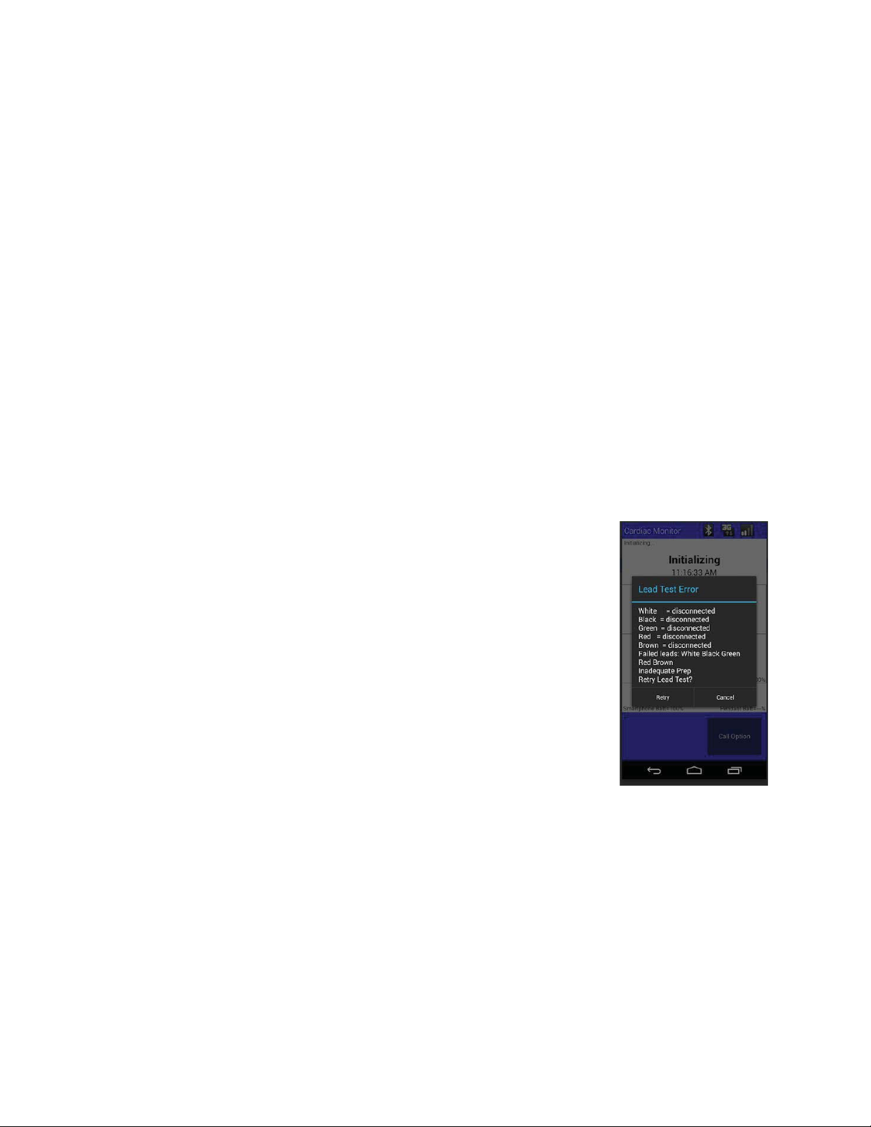
Have a question or need assistance?
TelePatch™ Cardiac Monitor PM750
Call Medicomp’s Patient Support: 877-996-5553
If inadequate signal voltage (can be either low or high) in one channel while the other one is
acceptable, place the electrodes in a “parallel”, or ”side-by-side” lead arrangement. Identify the channel
that has the acceptable voltage and place the electrodes of the problem channel side-by-side with it. For
example:
Channel A good, Channel B bad - place Black electrode next to White. Configuration will be:
Black and white electrodes on the right upper chest, and red electrode underneath the left
breast.
Channel B good, Channel A bad - place White next to Black. Configuration will be: black and
white electrodes on the right lower chest.
• Go to PATIENT PREPARATION for additional steps.
• For additional troubleshooting instructions, go to TROUBLESHOOTING OVERVIEW
Lead Position Tests
Lead Test Error
When a Lead Test Error occurs, the Handset displays a message similar
to:
THE WHITE ELECTRODE HAS A CONNECTION PROBLEM.
White = White electrode site (A-)
Red = Red electrode site (A+/B+)
Black = Black electrode site (B-)
Lead errors occur when the lead wire connected to the Cable Cradle
detects a very high resistance that may be caused by one or more of the
following conditions:
● Very high resistance values
● Expiration of Electrodes
● Cables disconnected
Very high resistance values
May indicate a problem with the cable. Try changing the cable first, if one is available,
otherwise move on to the next step.
USER MANUAL - UTM0000701-05E
66
| APRIL 4, 2019
Page 67

Have a question or need assistance?
Although the TelePatch System automatically adjusts the signal size (voltage) to ensure optimal
TelePatch™ Cardiac Monitor PM750
USER MANUAL - UTM0000701-05E | APRIL 4, 2019
Call Medicomp’s Patient Support: 877-996-5553
If not done so already, thoroughly wash the electrode site with PLAIN (no lotion or oil) soap and
water. Apply a small amount (about the size of the tip of a cotton swab) of Skin Prep gel to a
paper towel and firmly rub it into the skin at the gel cup site. Wipe off the excess gel. If no Skin
Prep is available, this can also be done with a rough, wet, washcloth. Always apply a new
electrode to the site. In difficult cases, light abrasion with a scrub pad may also be required; this
may occur with users who have very oily skin.
Press down on the center snap of the electrode and Tap 'Retry' on the Handset.
If the Universal Pendant
and Handset proceed through to 'Lead Position Test', then after all
tests are completed and the Handset is actively 'Monitoring,' change the electrode, this time
making sure that it is in good contact with the skin.
Expiration Date of Electrodes
Check the expiration date on the electrodes. Inspect the electrode(s) in question to verify moist
gel cups. If the gel is dry, you will need to replace the electrode.
Cables (lead wires) not connected
If the electrode cables are disconnected, this error message will also appear.
• Go to PATIENT PREPARATION for additional steps.
• For additional troubleshooting instructions, call Medicomp’s Patient Support: 877-996-5553.
High/Low Voltage Notifications
LOW VOLTAGE IN CHANNEL A
(WHITE [A-]/RED [A+] ELECTRODE PAIR)
analysis, some users may have cardiac anomalies that result in unacceptable signal voltage. The
signal may be too large or too small. The following section describes each error that might
occur. Sometimes, just having the patient lean back in a chair will increase the ECG voltage.
The Handset's message for this error is: Low A, Move Red
First, move the red electrode
After repositioning,
Press 'Retry'
If the Handset continues to display the error, try an electrode location on the opposite side of
the Red (A+/B+) electrode pictured. Don't try more than a few different locations.
67
Page 68

Have a question or need assistance?
TelePatch™ Cardiac Monitor PM750
USER MANUAL - UTM0000701-05E | APRIL 4, 2019
Call Medicomp’s Patient Support: 877-996-5553
• For additional troubleshooting instructions, call Medicomp’s Patient Support: 877-996-5553.
LOW VOLTAGE IN CHANNEL B
(BLACK [B-], RED [A+] ELECTRODE PAIR
The Handset's message for a low voltage in Channel B is: Low B, Move Black
First, move the black electrode
Low Voltage in Channel B, Move Black After repositioning,
Press 'Retry'
If the Handset continues to display the error, try an electrode location on the opposite side of
the Black (B-) electrode. Don't try more than a few different locations.
• For additional troubleshooting instructions, call Medicomp’s Patient Support: 877-996-5553.
HIGH VOLTAGE IN CHANNEL A
(RED [A+]/WHITE [A-] ELECTRODE PAIR)
The Handset's message for this error is: High A, Move Red
First, move the red electrode
High Voltage in Channel A, Move Red After repositioning,
Press 'Retry'
If the Handset continues to display the error, try an electrode location on the opposite side of
the Red (A+/B+) electrode. Don't try more than a few different locations.
• For additional troubleshooting instructions, call Medicomp’s Patient Support: 877-996-5553.
HIGH VOLTAGE IN CHANNEL B
(BLACK [B-]/RED [A+] ELECTRODE PAIR)
The Handset's message for a high voltage in Channel B is: High B, Move Black
First, move the black electrode
High Voltage in Channel B, Move Black After repositioning,
Press 'Retry'
If the Handset continues to display the error, try an electrode location on the opposite side of
the Black (B-) electrode pictured. Don't try more than a few different locations.
• For additional troubleshooting instructions, call Medicomp’s Patient Support: 877-996-5553.
68
Page 69
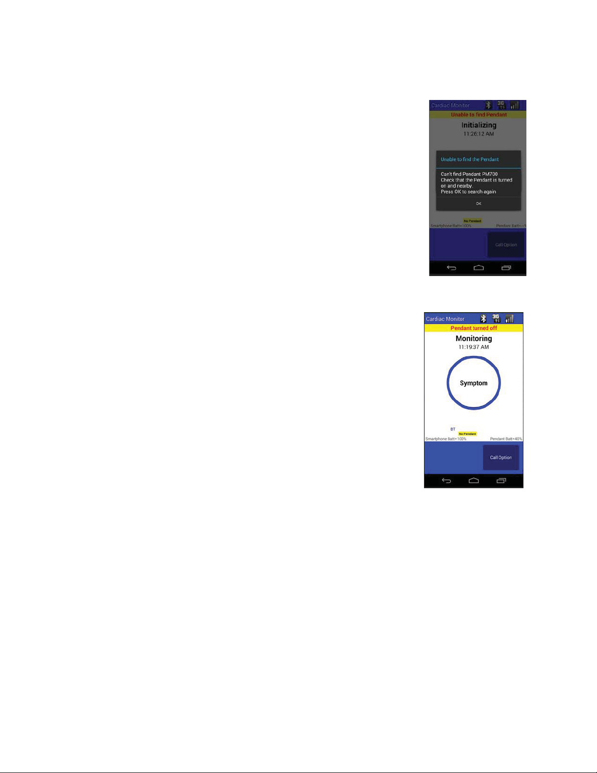
Have a question or need assistance?
Every TelePatch Kit has a postage paid return envelope. Include all
TelePatch™ Cardiac Monitor PM750
Call Medicomp’s Patient Support: 877-996-5553
SAMPLE SCREEN WARNINGS
Screen Warnings
There are a number of screen warnings that may appear on the Handset
screen. Below is a sampling of some of the most common screen
warnings.
Unable to find Pendant
At the very start of a new procedure, if the Handset IS turned on and the
Pendant is NOT turned on, the following warning or alert will be
displayed. Turn on the Pendant to proceed. While continuing a
procedure, if the Pendant is NOT turned on when the Handset IS turned
on, the following warning or alert will be displayed. Turn on the Pendant
to proceed.
Pendant is Turned Off
If the Pendant is turned off while in the middle of monitoring, the
following warning or alert will be displayed. Turn on the Pendant to
proceed.
Procedure Has Ended
When the procedure ends, an alert will be displayed. Users should
return the unit to the Medicomp address provided in the Patient Guide.
components in the zippered kit and mail from any mailbox.
• For additional troubleshooting instructions, call Medicomp’s Patient Support: 877-996-5553.
Start Procedure Exceptions
Selecting a Pendant
If more than one Pendant is identified after pressing 'Start Procedure,' the patient will be
prompted to 'Select a Pendant to Use.' The instructions below provide detail steps to select a
Pendant before starting a procedure.
Select a Pendant to Use
● User chooses from the list of Pendants on the screen
● Select the Pendant with the unique serial number listed inside the well of the Pendant.
USER MANUAL - UTM0000701-05E
69
| APRIL 4, 2019
Page 70
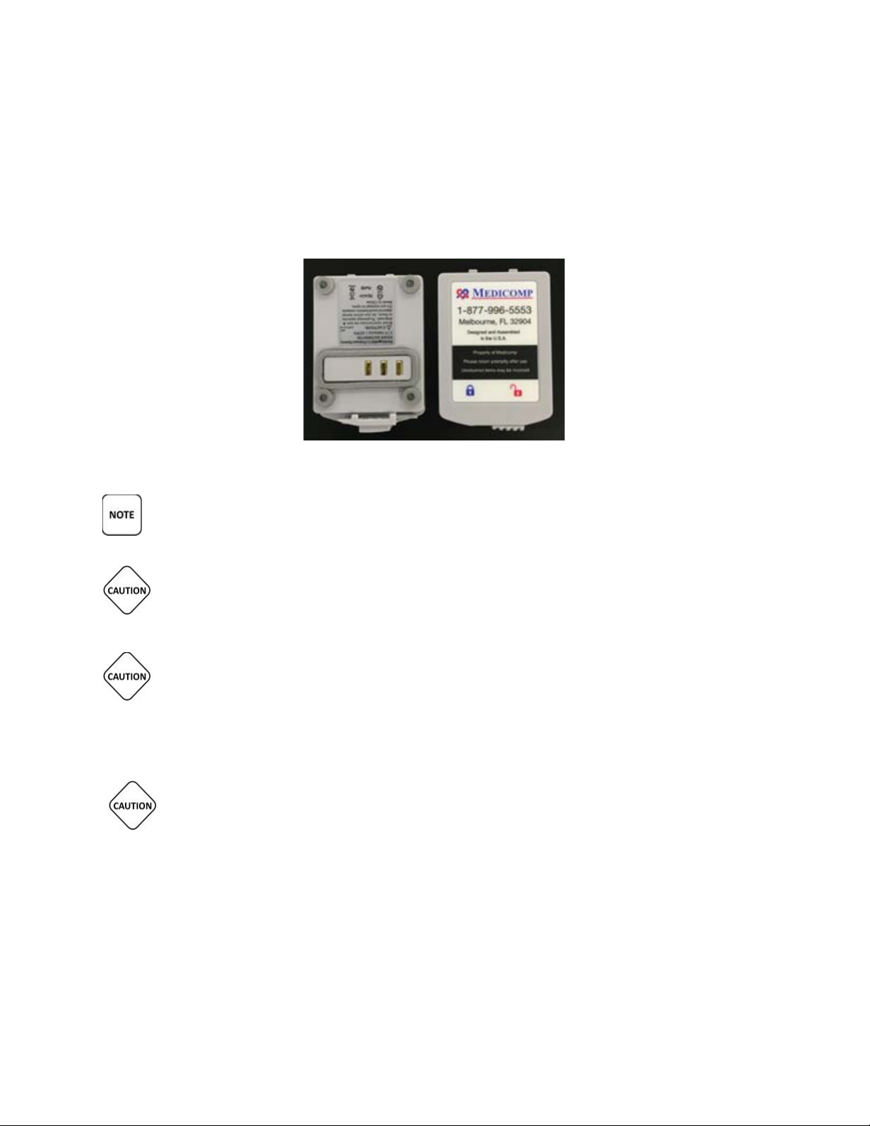
Have a question or need assistance?
The TelePatch Cardiac Monitor Pendant operates on a single, 3.7V lithium ion battery.
Bottom and top views of the Universal Pendant Battery
TelePatch™ Cardiac Monitor PM750
Call Medicomp’s Patient Support: 877-996-5553
● Tap and highlight the Pendant serial number.
● Tap 'Select'
SAFE BATTERY USE AND DISPOSAL
IF PENDANT’S BACKUP BATTERY IS LOW, PATIENT SHOULD CALL MEDICOMP PATIENT
SUPPORT: 800-234-3278 ext. 2370.
IT IS VERY IMPORTANT TO TURN THE PENDANT OFF BEFORE REMOVING AND
LOADING BATTERY, OTHERWISE DATA MAY BE LOST. REMINDER: THE POWER BUTTON
IS LOCATED ON THE FACE OF THE PENDANT, BELOW THE SYMPTOM BUTTON.
THIS PRODUCT UTILIZES A RECHARGEABLE LITHIUM-ION BATTERY PACK. TO ENSURE
SAFE CHARGING AND MAXIMUM PERFORMANCE OVER THE LIFE OF THE PRODUCT
ALWAYS USE THE MEDICOMP PROVIDED CHARGER. DO NOT ATTEMPT TO CHARGE
THE BATTERY ON ANOTHER MANUFACTURER’S CHARGER.
THIS PRODUCT UTILIZES A RECHARGEABLE LITHIUM-ION BATTERY PACK. ALL
BATTERIES WILL SLOWLY DISCHARGE OVER TIME EVEN IF THEY AREN’T USED. TO
ENSURE OPTIMAL PERFORMANCE AND LIFETIME OF THE BATTERY PACK, PLEASE
FULLY CHARGE THE BATTERY AT LEAST ONCE EVERY 6 MONTHS REGARDLESS OF USE. IT IS
FURTHER RECOMMENDED THAT IF THE BATTERY HASN’T BEEN CHARGED MORE RECENTLY
THAN A MONTH AGO THAT IT BE FULLY CHARGED PRIOR TO THE START OF A PATIENT
PROCEDURE.
USER MANUAL - UTM0000701-05E
70
| APRIL 4, 2019
Page 71
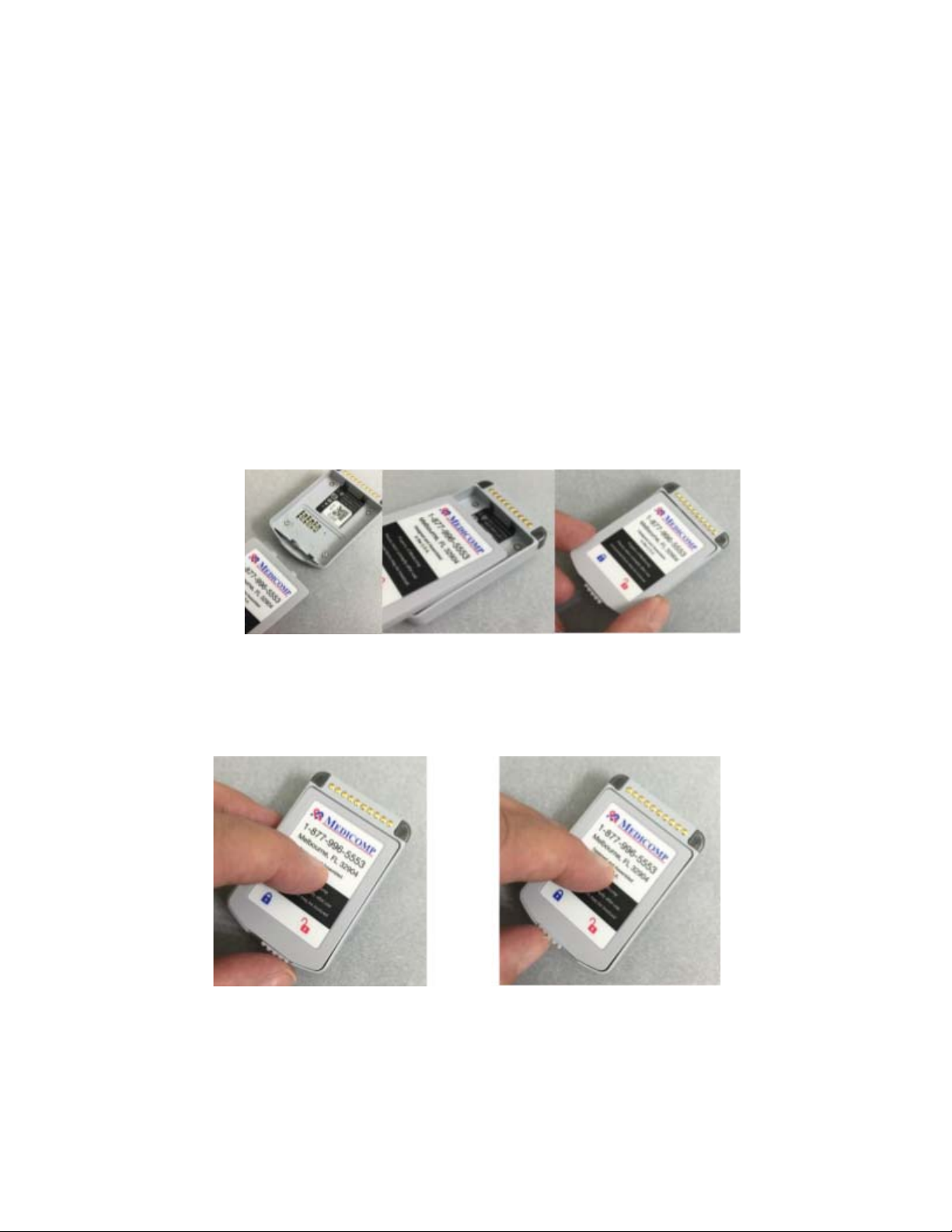
Have a question or need assistance?
TelePatch™ Cardiac Monitor PM750
Call Medicomp’s Patient Support: 877-996-5553
Safely Loading the Pendant Battery
Universal Pendant operates on a rechargeable, lithium ion battery. The battery locks into the
battery well of the back of the Universal Pendant.
To safely load the battery into the Pendant:
● Remove the Pendant and one battery from the zippered kit
Insert battery into Pendant.
● Hold Pendant face down in hand or place on a flat surface. There is a well where
battery will be inserted
● Insert battery into well of Pendant: with the Medicomp label facing up, and the two
small tabs into notches in flat wall of the well
Inserting battery into Pendant battery well
● Slide the latch at back of the battery to left, securing battery in place. Battery is locked
in place when moveable latch is under blue lock icon on label
Battery is unlocked (latch under RED icon) Battery Is locked (latch under BLUE icon)
USER MANUAL - UTM0000701-05E
71
| APRIL 4, 2019
Page 72
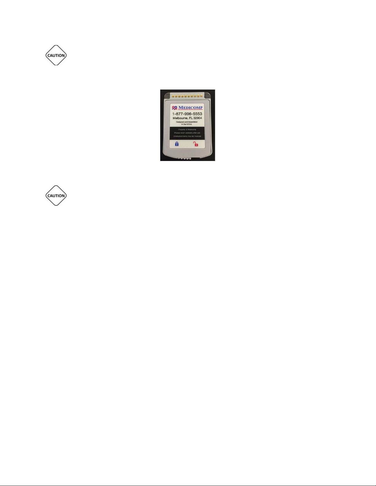
Have a question or need assistance?
LOAD ONLY 3.7V LITHIUM ION BATTERIES DELIVERED IN THE TELEPATCH KIT INTO THE
Properly inserted TelePatch Battery
TelePatch™ Cardiac Monitor PM750
Call Medicomp’s Patient Support: 877-996-5553
TELEPATCH CARDIAC MONITOR BATTERY COMPARTMENT.
IT IS VERY IMPORTANT TO TURN THE PENDANT OFF BEFORE CHANGING BATTERY,
OTHERWISE DATA MAY BE LOST. THE POWER BUTTON IS LOCATED ON THE FRONT FACE OF THE
PENDANT BELOW THE SYMPTOM BUTTON.
Battery Maintenance
● Remove the battery from the Pendant during storage or if the Pendant is not to be used
for longer than two (2) weeks.
● Store in a cool, dry place, the best location is in the TelePatch Cardiac Monitor Kit
supplied for your procedure.
Disposal of Rechargeable Lithium Ion Batteries
In accordance with federal laws and regional regulations:
● RETURN all batteries to Medicomp, Inc.
● The rechargeable battery provided with the TelePatch System is NOT to be discarded in
household waste.
● If a battery gets damaged contact Medicomp, Inc.: 877-996-5553
EXPLANATION OF MARKINGS
Equipment markings and caution labels are important for safe and reliable use; they must not
be removed. The following symbols are used in this user manual, patch packaging, lithium ion
battery or the Pendant label. They may also appear on an accessory or accessory packaging.
USER MANUAL - UTM0000701-05E
72
| APRIL 4, 2019
Page 73
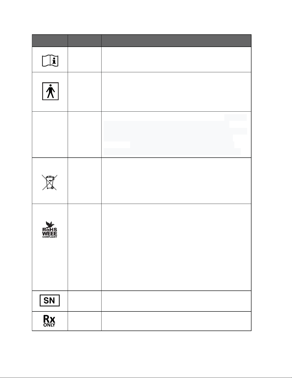
Have a question or need assistance?
Pendant,
Lanyard
Pendant
medical electrical equipment. Type BF equipment: equipment
Pendant
This symbol indicates Ingress protection- Solids: 5 – Ingress of
Pendant
Pendant.
Battery
Pendant
Patch
TelePatch™ Cardiac Monitor PM750
Call Medicomp’s Patient Support: 877-996-5553
Icon Description
Operating instructions
This symbol indicates type BF equipment classified in
accordance with IEC Publication IEC 60417-5333 Safety of
with isolated patient connections, connections not
defibrillation-proof.
IP55
Lithium Ion
dust is not entirely prevented, but it must not enter in
sufficient quantity to interfere with the satisfactory operation
of the equipment; complete protection against contact.
Liquids: 5 - Water projected by a nozzle (6.3mm) against
enclosure from any direction shall have no harmful effects.
This symbol informs the user that the respectively labeled
component is not to be disposed of in the trash.
Users should properly dispose of components through
Medicomp, Inc. Please contact Medicomp, Inc. for
information on how to return item for recycling.
WEEE LOGO
The WEEE logo on this product indicates that this product
must not be disposed of with standard waste but rather
recycled. Please contact Medicomp, Inc. for more information
on proper component disposal.
RoHS Compliance
This product is in compliance with Directive 2002/95/ EC of
the European Parliament and of the Council of 27 January
2003, on the restriction of the use of certain hazardous
substances in electrical and electronic equipment (RoHS) and
its amendments.
Serial Number
Prescription Required
USER MANUAL - UTM0000701-05E
73
| APRIL 4, 2019
Page 74
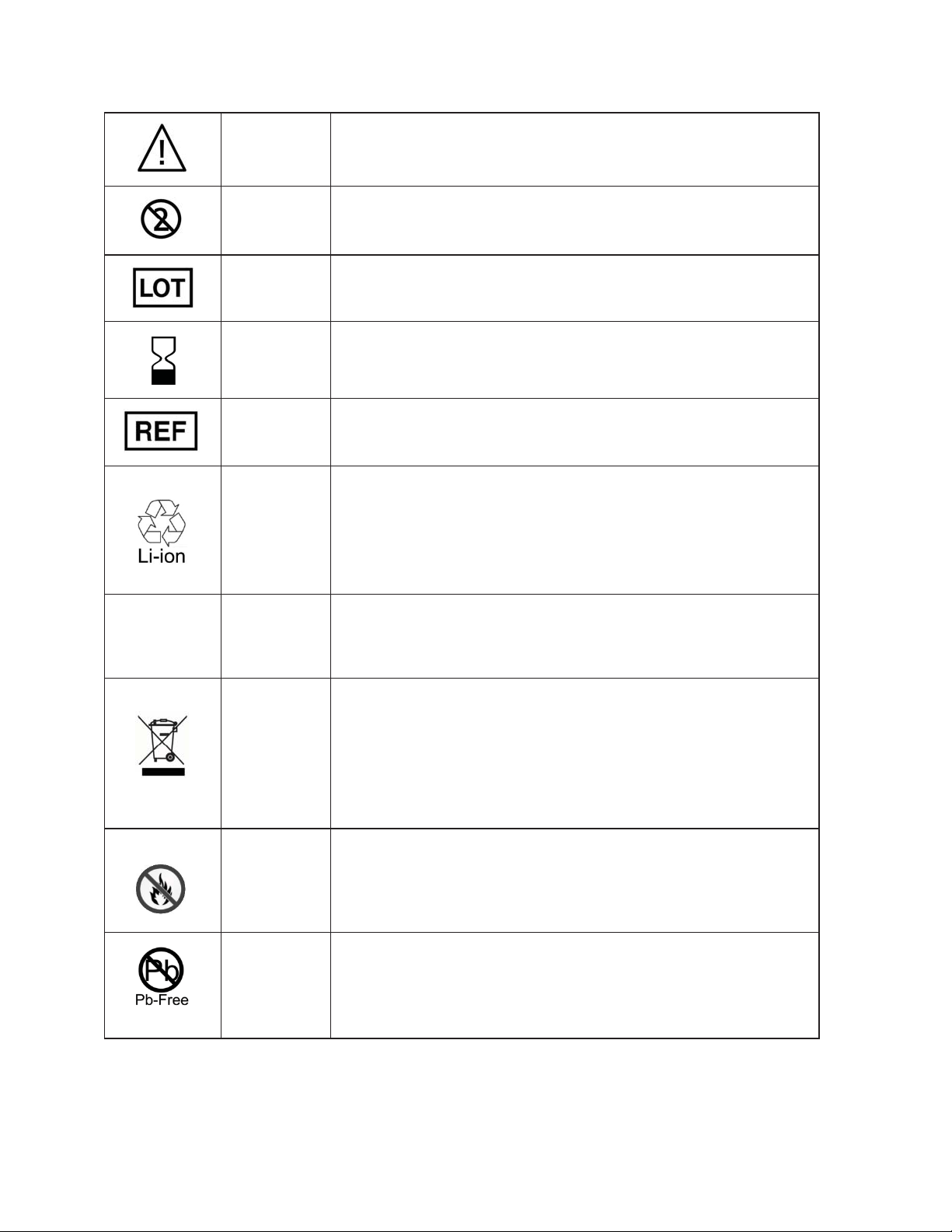
Have a question or need assistance?
Patch
Patch
Patch
Patch
Patch
Lithium Ion
Battery
Lithium Ion
Battery
Lithium Ion
Battery
Lithium Ion
Battery
Lithium Ion
Battery
TelePatch™ Cardiac Monitor PM750
Call Medicomp’s Patient Support: 877-996-5553
Caution, consult accompanying documents
Do not reuse. This is a single use item
Batch code of product
Use by date indicated
Catalog Number/Part Number
REACH
Item is recyclable.
Users should properly dispose of components through
Medicomp, Inc. Please contact Medicomp, Inc. for
information on how to return item for recycling.
EU regulation of chemicals and safe use: Registration,
Evaluation, Authorization and Restriction of Chemical
substances. Component substances are REACH approved.
Item must not be disposed of to the ‘normal’ household
waste, but be separately collected and recycled.
Users should properly dispose of components through
Medicomp, Inc. Please contact Medicomp, Inc. for
information on how to return item for recycling.
Do not incinerate
USER MANUAL - UTM0000701-05E
74
Product is lead free. Component and Assembly Pb content
shall be less than 0.1% by weight of the device (in accordance
with IPC/EIA J-STD-006) and shall not be intentionally
introduced.
| APRIL 4, 2019
Page 75
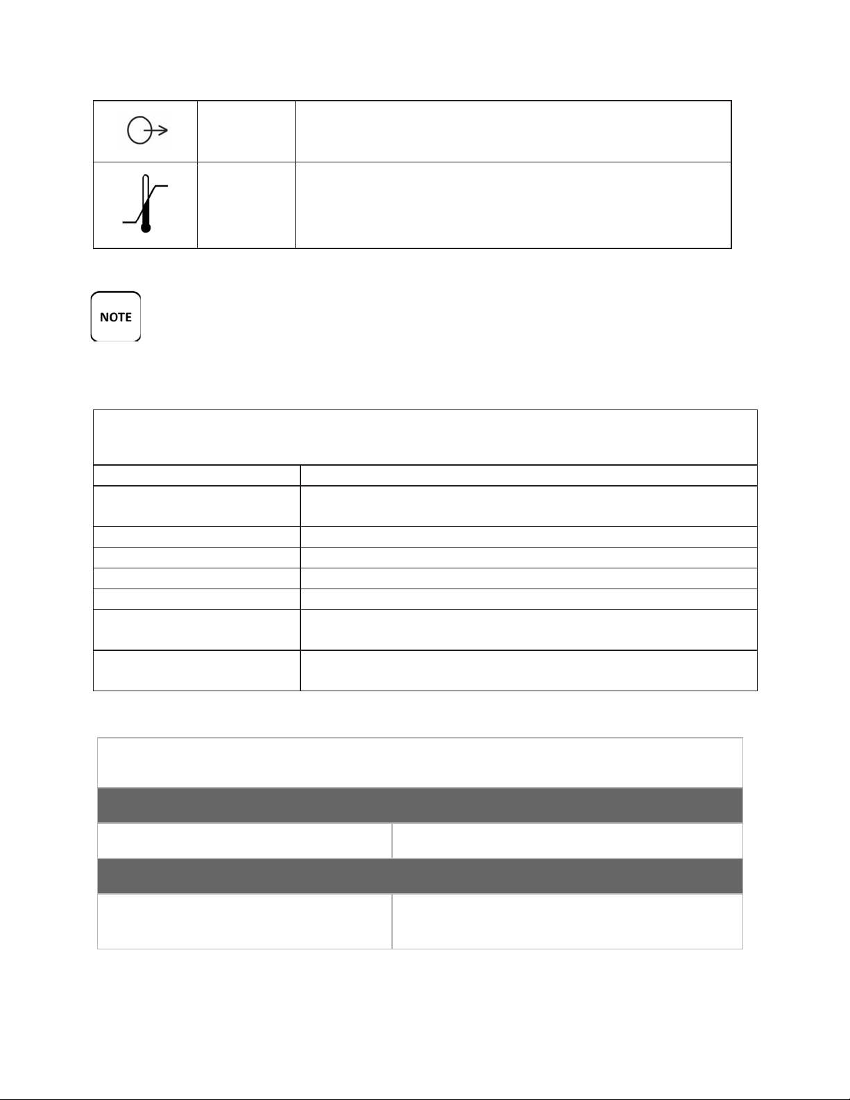
Have a question or need assistance?
Lead Wire
packaging
Shipping
packaging
Return TelePatch, Pendant, and all components in kit provided, to Medicomp,
Universal Pendant
Unit is expected to provide at least 7 years of normal use.
Electrode Patch with cradle
When the patch no longer sticks well to skin, dispose of in a
receptacle out of reach of children and pets.
Lithium Ion Battery
Each unit is expected to provide at least 7 years of normal use.
Battery Charger
Unit is expected to provide at least 7 years of normal use.
Cable Cradle
Unit is expected to provide at least 4 years of normal use.
3-Lead and 5-Lead Cables
Cables are expected to provide at least 6 months of normal use.
Electrodes
When the patch no longer sticks well to skin, dispose of in a
receptacle out of reach of children and pets.
Lanyard
When procedure complete dispose of in a receptacle out of
reach of children and pets.
TelePatch™ Cardiac Monitor PM750
Call Medicomp’s Patient Support: 877-996-5553
Lead wires comply with the Performance Standard for
electrode lead wires
Temperature limitation for shipment of system is -15°C to
60°C (5°F to 140°F).
● The Universal Pendant should NOT be treated as household waste.
● The Electrode Patch or individual electrodes ONLY should be discarded after use.
●
Inc., using the included postage paid envelope.
EXPECTED LIFE
PENDANT SPECIFICATIONS
Technical Features
Single button operation Records symptomatic ECG
Memory Characteristics
ECG Channels
Memory Card, Micro SD
USER MANUAL - UTM0000701-05E
75
| APRIL 4, 2019
1 and 2 Channel
4GB
Page 76
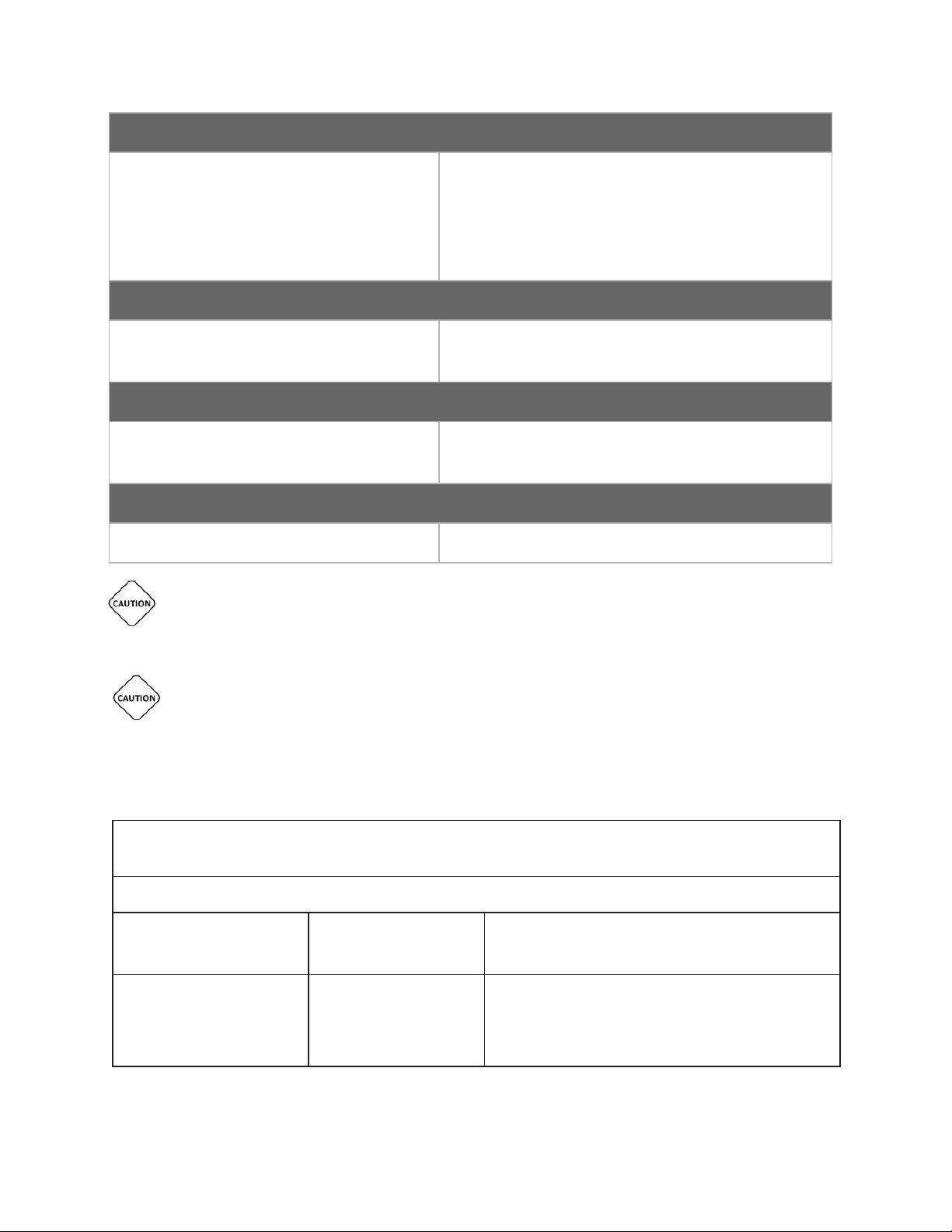
Have a question or need assistance?
1 Lithium Ion (rechargeable), 1 Coin cell (internal)
MEDICAL ELECTRICAL EQUIPMENT NEEDS SPECIAL PRECAUTIONS REGARDING EMC
USE THE TELEPATCH SYSTEM ONLY WITH THE LEADS, ELECTRODES, AND ACCESSORIES
TelePatch™ Cardiac Monitor PM750
Call Medicomp’s Patient Support: 877-996-5553
Electrical Characteristics
Frequency Response
Input Impedance
Differential Range
Sampling Rate
Resolution
0.05Hz to 100 Hz
Ӌ 10.0 Mohm
+/- 5.0mV A/D
250 samples/second
12 bits
Physical Characteristics
Dimensions
Weight
58mm x 38.5mm x 15.5mm
37.5g (Pendant only)
Power Requirements
Battery Type
Battery Life
7 days, typical usage
Environmental Durability
Pendant Waterproof Specification IP55
AND NEEDS TO BE INSTALLED AND PUT INTO SERVICE ACCORDING TO THE EMC
INFORMATION PROVIDED IN THIS MANUAL.
RECOMMENDED BY MEDICOMP. USE OF OTHER ACCESSORIES MAY ADVERSELY AFFECT
THE PERFORMANCE OF THE DEVICE OR MAY RESULT IN STRONGER ELECTROMAGNETIC
EMISSIONS OR REDUCE THE ELECTROMAGNETIC IMMUNITY OF TELEPATCH CARDIAC
MONITOR PM750.
GUIDANCE AND MANUFACTURER’S DECLARATION - ELECTROMAGNETIC EMISSIONS
The PM750 is intended for use in the electromagnetic environment specified below.
Emissions Test Compliance Electromagnetic Environment - Guidance
RF emissions CISPR 11 Group 1 The PM750 uses RF energy only for its internal
function. Therefore, its RF emissions are very low and
are not likely to cause any interference in nearby
electronic equipment.
USER MANUAL - UTM0000701-05E
76
| APRIL 4, 2019
Page 77

Have a question or need assistance?
IEC 60601
Test Level/Limits
2kV,4kV,6kV 8kV (+/-)
(+/-) AIR
±2.0kV AC/DC Mains
Lines
70% of Vnom, 25 cycles at
0% of Vnom, 1.0 cycles at
70% of Vnom, 25 cycles at
0deg, 45deg, 90deg, 180deg,
TelePatch™ Cardiac Monitor PM750
Call Medicomp’s Patient Support: 877-996-5553
RF emissions CISPR 11 Class B The PM750 is suitable for use in all establishments,
including domestic establishments and those directly
connected to the public low-voltage power supply
network that supplies buildings used for domestic
purposes
Harmonic emissions IEC
Not Applicable
61000-3-2
Voltage Fluctuations/ flicker
Not Applicable
emissions IEC 61000-3-3
GUIDANCE AND MANUFACTURER’S DECLARATION - ELECTROMAGNETIC IMMUNITY
The PM750 is intended for use in the electromagnetic environment specified below. The customer or user of
the PM750 should assure that it is used in such an environment.
Immunity Standards per 60601-1-2 :2014, (Home Healthcare Environmental) and ETSI EN301 489-1 V1.9.2
(2011-09)
Immunity Test
Compliance Limits Compliance Level
NOTE: EUT PM750 Pendant
shuts down between +/-8
and 15kV Air Discharge. It is
recommended that you
restart the device (wait 30
seconds after power down)
upon occurrence of this
event.
Electrostatic
discharge (ESD) IEC
61000-4-2
Electrical fast
transient/burst IEC
61000-4-4
Voltage Dips, short
interruptions and
voltage variations on
power supply input
lines IEC 61000-4-11
USER MANUAL - UTM0000701-05E
77
Contact 2kV,4kV,8kV, 15kV
±1kV Signal and Control
0deg
0% of Vnom, 0.5cycles at
0deg, 45deg, 90deg,
180deg, 225deg, 270deg,
315deg
2kV,4kV,6kV 8kV (+/-)
Contact 2kV,4kV,8kV,
15kV (+/-) AIR
±2.0kV AC/DC Mains
±1kV Signal and Control
Lines
0deg
0% of Vnom, 0.5cycles at
0deg, 45deg, 90deg,
180deg, 225deg, 270deg,
315deg
2kV,4kV,6kV 8kV (+/-)
Contact 2kV,4kV,8kV, 15kV
(+/-) AIR
±2.0kV AC/DC Mains
±1kV Signal and Control
Lines
70% of Vnom, 25 cycles at
0deg
0% of Vnom, 0.5cycles at
225deg, 270deg, 315deg
0% of Vnom, 1.0 cycles at
| APRIL 4, 2019
Page 78

Have a question or need assistance?
0deg
0% of Vnom cycles at 0deg
30 A/m (Both 50Hz, 60Hz)
30 A/m (Both 50Hz, 60Hz)
The PM750 is intended for use in the electromagnetic environment specified below. The customer or user of
Test Level/Limits
Compliance Limits
3Vrms 150kHz to 80MHz,
80% AM 1kHz
10 V/m, 80 MHz to 2.7
GHz, 80% AM 1kHz
710MHz, 745MH, 780MHz:
385MHz: 27V/m @ 18Hz
710MHz, 745MH, 780MHz:
TelePatch™ Cardiac Monitor PM750
Call Medicomp’s Patient Support: 877-996-5553
0% of Vnom, 1.0 cycles at
0deg
0deg
0% of Vnom cycles at 0deg
0% of Vnom cycles at
0deg
Power frequency
(50/60 Hz) magnetic
30 A/m (Both 50Hz, 60Hz)
field IEC 61000-4-8
NOTE: EUT PM750 Pendant shuts down between +/-8 and 15kV Air Discharge. It is recommended that you
restart the device (wait 30 seconds after power down) upon occurrence of this event.
GUIDANCE AND MANUFACTURER’S DECLARATION - ELECTROMAGNETIC IMMUNITY
the PM750 should assure that it is used in such an environment.
Immunity Standards per 60601-1-2 :2014, (Home Healthcare Environmental) and ETSI EN301 489-1 V1.9.2
(2011-09)
Immunity Test IEC 60601
Compliance Level
Conducted RF IEC
61000-4-6
Radio Frequency
Electromagnetic Field
Amplitude 61000-4-3
Radiated RF IEC
61000-4-3
3Vrms 150kHz to 80MHz,
80% AM 1kHz
10 V/m, 80 MHz to 2.7
GHz, 80% AM 1kHz
385MHz: 27V/m @ 18Hz
pulse modulation
450MHz: 28V/m @ FM
modulation
9V/m @
217 Hz pulse modulation
810MHz, 870MHz,
930MHz: 28V/m @
18Hz Pulse modulation
1720MHz, 1845MHz,
1970MHz: 28V/m @
217 Hz Pulse Modulation
pulse modulation,
450MHz: 28V/m @ FM
modulation
710MHz, 745MH,
780MHz: 9V/m @ 217 Hz
pulse modulation
810MHz, 870MHz,
930MHz: 28V/m @
18Hz Pulse modulation
1720MHz, 1845MHz,
1970MHz: 28V/m @
217 Hz Pulse Modulation
3Vrms 150kHz to 80MHz,
80% AM 1kHz
10 V/m, 80 MHz to 2.7
GHz, 80% AM 1kHz
385MHz: 27V/m @ 18Hz
pulse modulation,
450MHz: 28V/m @ FM
modulation
9V/m @ 217 Hz pulse
modulation
810MHz, 870MHz,
930MHz: 28V/m @
18Hz Pulse modulation
1720MHz, 1845MHz,
1970MHz: 28V/m @
217 Hz Pulse Modulation
USER MANUAL - UTM0000701-05E
78
| APRIL 4, 2019
Page 79

Have a question or need assistance?
2450MHz: 28V/m @ 217Hz
2450MHz: 28V/m @
The PM750 is intended for use in an electromagnetic environment in which radiated RF disturbances are
80 MHz to 800 MHz d =
800 MHz to 2.5 GHz d =
meters (m) can be estimated using the equation applicable to the frequency of the transmitter, where P is the
TelePatch™ Cardiac Monitor PM750
Call Medicomp’s Patient Support: 877-996-5553
2450MHz: 28V/m @ 217Hz
Pulse modulation
5240MHz, 5500MHz,
5785MHz: 9V/m @
217 Hz Pulse modulation
Pulse modulation
5240MHz, 5500MHz,
5785MHz: 9V/m @
217 Hz Pulse modulation
217Hz Pulse modulation
5240MHz, 5500MHz,
5785MHz: 9V/m @
217 Hz Pulse modulation
RECOMMENDED SEPARATION DISTANCES BETWEEN PORTABLE AND MOBILE RF
COMMUNICATIONS EQUIPMENT AND THE PM750
controlled. The customer or the user of PM750 can help prevent electromagnetic interference by maintaining a
minimum distance between portable and mobile RF communications equipment (transmitters) and the PM750
as recommended below, according to the maximum output power of the communications equipment.
Separation distance according to frequency of transmitter
Rated maximum output
of transmitter (W)
150 kHz to 80 MHz
d = 1.167ҀP
1.167ҀP
2.333ҀP
0.01 .12 .12 .23
0.1 .37 .37 .74
1 1.2 1.2 2.3
10 3.7 3.7 7.4
100 12 12 23
For transmitters rated at a maximum output power not listed above the recommended separation distance d in
maximum output power rating of the transmitter in watts (W) according to the transmitter manufacturer.
NOTE: 1 - At 80 MHZ and 800 MHZ, the separation distance for the higher frequency range applies.
NOTE: 2 - These guidelines may not apply in all situations. Electromagnetic propagation is affected by absorption
and reflection from structures, objects and people.
USER MANUAL - UTM0000701-05E
| APRIL 4, 2019
79
 Loading...